JP2022532147A - Percussive treatment device with active control - Google Patents
Percussive treatment device with active control Download PDFInfo
- Publication number
- JP2022532147A JP2022532147A JP2021566309A JP2021566309A JP2022532147A JP 2022532147 A JP2022532147 A JP 2022532147A JP 2021566309 A JP2021566309 A JP 2021566309A JP 2021566309 A JP2021566309 A JP 2021566309A JP 2022532147 A JP2022532147 A JP 2022532147A
- Authority
- JP
- Japan
- Prior art keywords
- attachment
- percussive
- user
- force
- massage device
- Prior art date
- Legal status (The legal status is an assumption and is not a legal conclusion. Google has not performed a legal analysis and makes no representation as to the accuracy of the status listed.)
- Pending
Links
- 238000011282 treatment Methods 0.000 title claims description 105
- 230000004044 response Effects 0.000 claims abstract description 14
- 238000000034 method Methods 0.000 claims description 97
- 230000033001 locomotion Effects 0.000 claims description 39
- 230000001225 therapeutic effect Effects 0.000 claims description 17
- 230000000977 initiatory effect Effects 0.000 claims description 9
- 230000000007 visual effect Effects 0.000 claims description 3
- 238000012544 monitoring process Methods 0.000 claims description 2
- 238000002560 therapeutic procedure Methods 0.000 abstract description 9
- 230000003213 activating effect Effects 0.000 abstract description 2
- 210000003811 finger Anatomy 0.000 description 19
- 230000006870 function Effects 0.000 description 14
- 210000003205 muscle Anatomy 0.000 description 14
- 206010065303 Medial Tibial Stress Syndrome Diseases 0.000 description 11
- 230000008859 change Effects 0.000 description 10
- 238000010586 diagram Methods 0.000 description 10
- 238000013016 damping Methods 0.000 description 9
- 238000005259 measurement Methods 0.000 description 9
- 229920001971 elastomer Polymers 0.000 description 8
- 230000008878 coupling Effects 0.000 description 7
- 238000010168 coupling process Methods 0.000 description 7
- 238000005859 coupling reaction Methods 0.000 description 7
- 238000006880 cross-coupling reaction Methods 0.000 description 7
- 238000011084 recovery Methods 0.000 description 6
- 230000008569 process Effects 0.000 description 5
- 238000012545 processing Methods 0.000 description 5
- 239000000725 suspension Substances 0.000 description 5
- 230000009471 action Effects 0.000 description 4
- 239000000806 elastomer Substances 0.000 description 4
- 238000012986 modification Methods 0.000 description 4
- 230000004048 modification Effects 0.000 description 4
- 239000004033 plastic Substances 0.000 description 4
- RVCKCEDKBVEEHL-UHFFFAOYSA-N 2,3,4,5,6-pentachlorobenzyl alcohol Chemical compound OCC1=C(Cl)C(Cl)=C(Cl)C(Cl)=C1Cl RVCKCEDKBVEEHL-UHFFFAOYSA-N 0.000 description 3
- 241001417494 Sciaenidae Species 0.000 description 3
- 230000009286 beneficial effect Effects 0.000 description 3
- 230000008901 benefit Effects 0.000 description 3
- 244000309466 calf Species 0.000 description 3
- 238000001514 detection method Methods 0.000 description 3
- 230000007246 mechanism Effects 0.000 description 3
- 238000003825 pressing Methods 0.000 description 3
- 230000009467 reduction Effects 0.000 description 3
- 238000005096 rolling process Methods 0.000 description 3
- 238000012549 training Methods 0.000 description 3
- 230000017531 blood circulation Effects 0.000 description 2
- 210000000988 bone and bone Anatomy 0.000 description 2
- 239000013536 elastomeric material Substances 0.000 description 2
- 210000004247 hand Anatomy 0.000 description 2
- JVTAAEKCZFNVCJ-UHFFFAOYSA-N lactic acid Chemical compound CC(O)C(O)=O JVTAAEKCZFNVCJ-UHFFFAOYSA-N 0.000 description 2
- 239000000463 material Substances 0.000 description 2
- 208000019888 Circadian rhythm sleep disease Diseases 0.000 description 1
- 230000005355 Hall effect Effects 0.000 description 1
- 208000001456 Jet Lag Syndrome Diseases 0.000 description 1
- 208000007101 Muscle Cramp Diseases 0.000 description 1
- 208000002193 Pain Diseases 0.000 description 1
- 208000010332 Plantar Fasciitis Diseases 0.000 description 1
- 208000008765 Sciatica Diseases 0.000 description 1
- 208000005392 Spasm Diseases 0.000 description 1
- 239000000853 adhesive Substances 0.000 description 1
- 230000001070 adhesive effect Effects 0.000 description 1
- 230000000712 assembly Effects 0.000 description 1
- 238000000429 assembly Methods 0.000 description 1
- 239000003990 capacitor Substances 0.000 description 1
- 238000004891 communication Methods 0.000 description 1
- 238000007796 conventional method Methods 0.000 description 1
- 230000001419 dependent effect Effects 0.000 description 1
- 238000013461 design Methods 0.000 description 1
- 201000010099 disease Diseases 0.000 description 1
- 208000037265 diseases, disorders, signs and symptoms Diseases 0.000 description 1
- 230000000694 effects Effects 0.000 description 1
- 239000006260 foam Substances 0.000 description 1
- 208000033915 jet lag type circadian rhythm sleep disease Diseases 0.000 description 1
- 235000014655 lactic acid Nutrition 0.000 description 1
- 239000004310 lactic acid Substances 0.000 description 1
- 239000004973 liquid crystal related substance Substances 0.000 description 1
- 210000004705 lumbosacral region Anatomy 0.000 description 1
- 238000004519 manufacturing process Methods 0.000 description 1
- 230000002093 peripheral effect Effects 0.000 description 1
- 230000021715 photosynthesis, light harvesting Effects 0.000 description 1
- 238000002360 preparation method Methods 0.000 description 1
- 210000001991 scapula Anatomy 0.000 description 1
- 125000006850 spacer group Chemical group 0.000 description 1
- 238000006467 substitution reaction Methods 0.000 description 1
- 210000003813 thumb Anatomy 0.000 description 1
- 238000009423 ventilation Methods 0.000 description 1
- 238000005406 washing Methods 0.000 description 1
Images


Classifications
-
- A—HUMAN NECESSITIES
- A61—MEDICAL OR VETERINARY SCIENCE; HYGIENE
- A61H—PHYSICAL THERAPY APPARATUS, e.g. DEVICES FOR LOCATING OR STIMULATING REFLEX POINTS IN THE BODY; ARTIFICIAL RESPIRATION; MASSAGE; BATHING DEVICES FOR SPECIAL THERAPEUTIC OR HYGIENIC PURPOSES OR SPECIFIC PARTS OF THE BODY
- A61H23/00—Percussion or vibration massage, e.g. using supersonic vibration; Suction-vibration massage; Massage with moving diaphragms
- A61H23/006—Percussion or tapping massage
-
- A—HUMAN NECESSITIES
- A61—MEDICAL OR VETERINARY SCIENCE; HYGIENE
- A61H—PHYSICAL THERAPY APPARATUS, e.g. DEVICES FOR LOCATING OR STIMULATING REFLEX POINTS IN THE BODY; ARTIFICIAL RESPIRATION; MASSAGE; BATHING DEVICES FOR SPECIAL THERAPEUTIC OR HYGIENIC PURPOSES OR SPECIFIC PARTS OF THE BODY
- A61H23/00—Percussion or vibration massage, e.g. using supersonic vibration; Suction-vibration massage; Massage with moving diaphragms
- A61H23/02—Percussion or vibration massage, e.g. using supersonic vibration; Suction-vibration massage; Massage with moving diaphragms with electric or magnetic drive
- A61H23/0254—Percussion or vibration massage, e.g. using supersonic vibration; Suction-vibration massage; Massage with moving diaphragms with electric or magnetic drive with rotary motor
-
- A—HUMAN NECESSITIES
- A61—MEDICAL OR VETERINARY SCIENCE; HYGIENE
- A61H—PHYSICAL THERAPY APPARATUS, e.g. DEVICES FOR LOCATING OR STIMULATING REFLEX POINTS IN THE BODY; ARTIFICIAL RESPIRATION; MASSAGE; BATHING DEVICES FOR SPECIAL THERAPEUTIC OR HYGIENIC PURPOSES OR SPECIFIC PARTS OF THE BODY
- A61H2201/00—Characteristics of apparatus not provided for in the preceding codes
- A61H2201/01—Constructive details
- A61H2201/0119—Support for the device
- A61H2201/0153—Support for the device hand-held
-
- A—HUMAN NECESSITIES
- A61—MEDICAL OR VETERINARY SCIENCE; HYGIENE
- A61H—PHYSICAL THERAPY APPARATUS, e.g. DEVICES FOR LOCATING OR STIMULATING REFLEX POINTS IN THE BODY; ARTIFICIAL RESPIRATION; MASSAGE; BATHING DEVICES FOR SPECIAL THERAPEUTIC OR HYGIENIC PURPOSES OR SPECIFIC PARTS OF THE BODY
- A61H2201/00—Characteristics of apparatus not provided for in the preceding codes
- A61H2201/01—Constructive details
- A61H2201/0165—Damping, vibration related features
- A61H2201/0169—Noise reduction
-
- A—HUMAN NECESSITIES
- A61—MEDICAL OR VETERINARY SCIENCE; HYGIENE
- A61H—PHYSICAL THERAPY APPARATUS, e.g. DEVICES FOR LOCATING OR STIMULATING REFLEX POINTS IN THE BODY; ARTIFICIAL RESPIRATION; MASSAGE; BATHING DEVICES FOR SPECIAL THERAPEUTIC OR HYGIENIC PURPOSES OR SPECIFIC PARTS OF THE BODY
- A61H2201/00—Characteristics of apparatus not provided for in the preceding codes
- A61H2201/12—Driving means
- A61H2201/1207—Driving means with electric or magnetic drive
- A61H2201/1215—Rotary drive
-
- A—HUMAN NECESSITIES
- A61—MEDICAL OR VETERINARY SCIENCE; HYGIENE
- A61H—PHYSICAL THERAPY APPARATUS, e.g. DEVICES FOR LOCATING OR STIMULATING REFLEX POINTS IN THE BODY; ARTIFICIAL RESPIRATION; MASSAGE; BATHING DEVICES FOR SPECIAL THERAPEUTIC OR HYGIENIC PURPOSES OR SPECIFIC PARTS OF THE BODY
- A61H2201/00—Characteristics of apparatus not provided for in the preceding codes
- A61H2201/14—Special force transmission means, i.e. between the driving means and the interface with the user
- A61H2201/1481—Special movement conversion means
- A61H2201/149—Special movement conversion means rotation-linear or vice versa
-
- A—HUMAN NECESSITIES
- A61—MEDICAL OR VETERINARY SCIENCE; HYGIENE
- A61H—PHYSICAL THERAPY APPARATUS, e.g. DEVICES FOR LOCATING OR STIMULATING REFLEX POINTS IN THE BODY; ARTIFICIAL RESPIRATION; MASSAGE; BATHING DEVICES FOR SPECIAL THERAPEUTIC OR HYGIENIC PURPOSES OR SPECIFIC PARTS OF THE BODY
- A61H2201/00—Characteristics of apparatus not provided for in the preceding codes
- A61H2201/16—Physical interface with patient
- A61H2201/1602—Physical interface with patient kind of interface, e.g. head rest, knee support or lumbar support
- A61H2201/1635—Hand or arm, e.g. handle
-
- A—HUMAN NECESSITIES
- A61—MEDICAL OR VETERINARY SCIENCE; HYGIENE
- A61H—PHYSICAL THERAPY APPARATUS, e.g. DEVICES FOR LOCATING OR STIMULATING REFLEX POINTS IN THE BODY; ARTIFICIAL RESPIRATION; MASSAGE; BATHING DEVICES FOR SPECIAL THERAPEUTIC OR HYGIENIC PURPOSES OR SPECIFIC PARTS OF THE BODY
- A61H2201/00—Characteristics of apparatus not provided for in the preceding codes
- A61H2201/16—Physical interface with patient
- A61H2201/1683—Surface of interface
- A61H2201/1685—Surface of interface interchangeable
-
- A—HUMAN NECESSITIES
- A61—MEDICAL OR VETERINARY SCIENCE; HYGIENE
- A61H—PHYSICAL THERAPY APPARATUS, e.g. DEVICES FOR LOCATING OR STIMULATING REFLEX POINTS IN THE BODY; ARTIFICIAL RESPIRATION; MASSAGE; BATHING DEVICES FOR SPECIAL THERAPEUTIC OR HYGIENIC PURPOSES OR SPECIFIC PARTS OF THE BODY
- A61H2201/00—Characteristics of apparatus not provided for in the preceding codes
- A61H2201/50—Control means thereof
- A61H2201/5007—Control means thereof computer controlled
-
- A—HUMAN NECESSITIES
- A61—MEDICAL OR VETERINARY SCIENCE; HYGIENE
- A61H—PHYSICAL THERAPY APPARATUS, e.g. DEVICES FOR LOCATING OR STIMULATING REFLEX POINTS IN THE BODY; ARTIFICIAL RESPIRATION; MASSAGE; BATHING DEVICES FOR SPECIAL THERAPEUTIC OR HYGIENIC PURPOSES OR SPECIFIC PARTS OF THE BODY
- A61H2201/00—Characteristics of apparatus not provided for in the preceding codes
- A61H2201/50—Control means thereof
- A61H2201/5023—Interfaces to the user
- A61H2201/5025—Activation means
-
- A—HUMAN NECESSITIES
- A61—MEDICAL OR VETERINARY SCIENCE; HYGIENE
- A61H—PHYSICAL THERAPY APPARATUS, e.g. DEVICES FOR LOCATING OR STIMULATING REFLEX POINTS IN THE BODY; ARTIFICIAL RESPIRATION; MASSAGE; BATHING DEVICES FOR SPECIAL THERAPEUTIC OR HYGIENIC PURPOSES OR SPECIFIC PARTS OF THE BODY
- A61H2201/00—Characteristics of apparatus not provided for in the preceding codes
- A61H2201/50—Control means thereof
- A61H2201/5023—Interfaces to the user
- A61H2201/5043—Displays
- A61H2201/5046—Touch screens
-
- A—HUMAN NECESSITIES
- A61—MEDICAL OR VETERINARY SCIENCE; HYGIENE
- A61H—PHYSICAL THERAPY APPARATUS, e.g. DEVICES FOR LOCATING OR STIMULATING REFLEX POINTS IN THE BODY; ARTIFICIAL RESPIRATION; MASSAGE; BATHING DEVICES FOR SPECIAL THERAPEUTIC OR HYGIENIC PURPOSES OR SPECIFIC PARTS OF THE BODY
- A61H2201/00—Characteristics of apparatus not provided for in the preceding codes
- A61H2201/50—Control means thereof
- A61H2201/5058—Sensors or detectors
- A61H2201/5061—Force sensors
-
- A—HUMAN NECESSITIES
- A61—MEDICAL OR VETERINARY SCIENCE; HYGIENE
- A61H—PHYSICAL THERAPY APPARATUS, e.g. DEVICES FOR LOCATING OR STIMULATING REFLEX POINTS IN THE BODY; ARTIFICIAL RESPIRATION; MASSAGE; BATHING DEVICES FOR SPECIAL THERAPEUTIC OR HYGIENIC PURPOSES OR SPECIFIC PARTS OF THE BODY
- A61H2201/00—Characteristics of apparatus not provided for in the preceding codes
- A61H2201/50—Control means thereof
- A61H2201/5097—Control means thereof wireless
Landscapes
- Health & Medical Sciences (AREA)
- Epidemiology (AREA)
- Pain & Pain Management (AREA)
- Physical Education & Sports Medicine (AREA)
- Rehabilitation Therapy (AREA)
- Life Sciences & Earth Sciences (AREA)
- Animal Behavior & Ethology (AREA)
- General Health & Medical Sciences (AREA)
- Public Health (AREA)
- Veterinary Medicine (AREA)
- Percussion Or Vibration Massage (AREA)
Abstract
パーカッシブ治療装置であって、ハウジングと、電源と、ハウジングに配置されたモータと、モータを作動させるためのスイッチと、ユーザ入力に応答してパーカッシブ治療装置の少なくとも一つの出力を適用するように構成されたプロトコルを開始するとともに少なくとも一つの出力に従ってパーカッシブ治療装置に適用されるプロトコルの少なくとも一つのステップを開始するように構成されたルーチンコントローラと、を備えるパーカッシブ治療装置。A percussive therapy device configured to apply at least one output of the percussive therapy device in response to a housing, a power source, a motor disposed in the housing, a switch for activating the motor, and a user input. a routine controller configured to initiate the protocol provided and to initiate at least one step of the protocol applied to the percussive therapy device according to the at least one output.
Description
関連出願の相互参照
この出願は、2019年5月7日に出願された米国仮出願第62/844,424号、2019年9月11日に出願された米国仮出願第62/899,098号及び2019年10月8日に出願された米国仮出願第62/912,392号の利益を主張する2020年2月20日に出願された米国特許出願第16/796,143号の一部継続出願である。この出願は、2018年12月26日に出願された米国仮出願第62/785,151号の利益を主張する2019年11月6日に提出された出願された米国特許出願第16/675,772号の一部継続出願でもある。上述した全ての出願は、参照により本明細書に組み込まれる。
Mutual reference to related applications This application is a US provisional application No. 62 / 844,424 filed May 7, 2019, and a US provisional application No. 62 / 899,098 filed September 11, 2019. And a partial continuation of US Patent Application No. 16 / 769,143 filed on February 20, 2020, claiming the interests of US Provisional Application No. 62 / 912,392 filed on October 8, 2019. It is an application. This application claims the benefit of US Provisional Application No. 62 / 785, 151 filed December 26, 2018, filed US Patent Application No. 16 / 675, filed November 6, 2019. It is also a partial continuation application of No. 772. All the applications mentioned above are incorporated herein by reference.
本発明は、一般的には、マッサージ機器に関し、更に具体的には、往復運動を行うパーカッシブ治療装置に関する。 The present invention generally relates to a massage device, and more specifically to a percussive treatment device that performs reciprocating motion.
マッサージ機器は、表面的で実際の利益をもたらさない効果のないマッサージを行うことがよくある。したがって、改良されたマッサージ装置が必要である。さらに、パーカッシブマッサージ機器は、効果のない方法でしばしば使用される。したがって、効果的なマッサージ又は回復を行うために、パーカッシブ治療装置を自動化する必要がある。 Massage equipment often provides superficial, ineffective massages that do not bring real benefits. Therefore, an improved massage device is needed. In addition, percussive massage devices are often used in ineffective ways. Therefore, it is necessary to automate the percussive treatment device for effective massage or recovery.
本発明の第1の態様によれば、パーカッシブ治療装置又はパーカッシブマッサージ機器であって、ハウジングと、電源と、ハウジングに配置されたモータと、モータを作動させるためのスイッチと、ユーザ入力に応答してパーカッシブ治療装置の少なくとも一つの出力を適用するように構成されたプロトコルを開始するとともに少なくとも一つの出力に従って治療装置に適用されるプロトコルの少なくとも一つのステップを開始するように構成されたルーチンコントローラと、を備えるパーカッシブ治療装置又はパーカッシブマッサージ機器を提供する。パーカッシブマッサージ機器及びパーカッシブ療法装置という用語は、全体を通して交換可能に使用されることが理解される。これらの用語は、同義語であり、一般的に同一の意味を有する。出願人の装置の商業的実施形態は、一般的には、市場ではパーカッシブ治療装置と呼ばれているため、ここでは、この用語を使用する。 According to the first aspect of the present invention, it is a percussive treatment device or a percussive massage device, which responds to a housing, a power supply, a motor arranged in the housing, a switch for operating the motor, and a user input. With a routine controller configured to initiate at least one output of the percussive treatment device and at least one step of the protocol applied to the treatment device according to at least one output. Provided is a percussive treatment device or a percussive massage device provided with. It is understood that the terms percussive massage device and percussive therapy device are used interchangeably throughout. These terms are synonyms and generally have the same meaning. The term is used herein because the commercial embodiment of the applicant's device is commonly referred to in the market as a percussive therapeutic device.
好適な実施形態では、少なくとも一つの出力は、(自動的に又はユーザがプロンプトを介してオン及びオフにすることによって)パーカッシブ治療装置を作動する期間、(自動的に又はユーザがプロンプトを介してある速度から他の速度に切り替えることによる)パーカッシブ治療装置のアタッチメントの速度、(ユーザが装置を使用することにより)アタッチメントによって加えられる力、アタッチメントの振幅及びアタッチメントの温度のうちの一つ以上を備える。 In a preferred embodiment, at least one output is for the duration of operation of the percussive treatment device (automatically or by the user turning it on and off via a prompt), (automatically or by the user via a prompt). It comprises one or more of the speed of the attachment of the percussive treatment device (by switching from one speed to another), the force applied by the attachment (by the user using the device), the amplitude of the attachment and the temperature of the attachment. ..
好適な実施形態では、パーカッシブ治療装置は、パーカッシブ治療装置のアタッチメントによって加えられる力を監視及び表示するように構成されたフォースメーターを有する。力の表示がユーザに提供され、力がプロトコルのうちの少なくとも一つのステップの間に加えられる(目標の力の範囲を含むように定義されてもよい)目標の力に対応するようにユーザが力を調整できるように構成される。 In a preferred embodiment, the percussive treatment device has a force meter configured to monitor and display the force applied by the attachment of the percussive treatment device. A force display is provided to the user and the user responds to the target force (which may be defined to include the target force range) to which the force is applied during at least one step of the protocol. It is configured so that the force can be adjusted.
好適な実施形態では、パーカッシブ治療装置は、(例えば、電話又はタブレットのようなユーザモバイル機器の)ユーザインターフェースを提供するように構成されたアプリケーション(ソフトウェアアプリケーション又はアプリ)を有する又はそれと通信を行うように構成される。好適には、パーカッシブ治療装置は、ユーザインターフェースを提供するように構成されたタッチスクリーンを有する又はユーザインターフェースを提供する。好適な実施形態では、パーカッシブマッサージ機器の指定されたグリップを使用することをユーザに促す(例えば、アプリを介して視覚的、聴覚的又は触覚的に、パーカッシブ治療装置のタッチスクリーンを視覚的、聴覚的若しくは触覚的に又は別の画面若しくは可聴を介して促す。)。 In a preferred embodiment, the percussive treatment device has or communicates with an application (software application or app) configured to provide a user interface (eg, for a user mobile device such as a telephone or tablet). It is composed of. Preferably, the percussive treatment device has or provides a touch screen configured to provide a user interface. In a preferred embodiment, the user is encouraged to use the specified grip of the percussive massage device (eg, visually, audibly or tactilely, visually, audibly, to the touch screen of the percussive treatment device via the app. Prompt, either objectively or tactilely, or through another screen or audible.)
好適な実施形態では、パーカッシブ治療装置のアタッチメントを指定された身体の部分に適用することを(例えば、視覚的、聴覚的又は触覚的に)ユーザに促す。好適には、パーカッシブ治療装置のアーム位置を設定することを(例えば、視覚的、聴覚的又は触覚的に)ユーザに促す。パーカッシブ治療は、一般的には、少なくとも一つのステップの間に触覚フィードバック、音、視覚的表現(例えば、画像、グラフィックス等)及びテキストのうちの少なくとも一つを介して少なくとも一つの出力を適用することをユーザに促す。好適な実施形態では、プロトコルの少なくとも一つのステップの間に指定された身体の部分の開始点から終了点にアタッチメントを移動することを(例えば、視覚的、聴覚的又は触覚的に)ユーザに促す。 In a preferred embodiment, the user is urged (eg, visually, audibly or tactilely) to apply the attachment of the percussive treatment device to a designated body part. Preferably, the user is urged (eg, visually, audibly or tactilely) to set the arm position of the percussive treatment device. Percussive treatment generally applies at least one output via at least one of tactile feedback, sound, visual representation (eg, images, graphics, etc.) and text during at least one step. Encourage the user to do so. In a preferred embodiment, the user is urged (eg, visually, audibly or tactilely) to move the attachment from the start point to the end point of a designated body part during at least one step of the protocol. ..
本発明の別の態様によれば、パーカッシブ治療装置のルーチンを実行する方法を提供する。方法は、ユーザ入力に応答してパーカッシブ治療装置の少なくとも一つの出力を適用するように構成されたプロトコルを開始することと、少なくとも一つの出力に従って、パーカッシブ治療装置が適用されるプロトコルの少なくとも一つのステップを実行することと、を有する。好適な実施形態では、少なくとも一つの出力は、(自動的に又はユーザによって)パーカッシブ治療装置を作動する期間、パーカッシブ治療装置のアタッチメントの速度、アタッチメントの力、アタッチメントの振幅、アタッチメントのタイプ、アタッチメントの温度、パーカッシブ治療装置のアーム位置及びパーカッシブ治療装置のグリップのうちの一つ以上を有する。 According to another aspect of the invention, there is provided a method of performing a routine of a percussive treatment device. The method initiates a protocol configured to apply at least one output of the percussive treatment device in response to user input, and at least one of the protocols to which the percussive treatment device is applied according to at least one output. To carry out the steps and to have. In a preferred embodiment, at least one output is the duration of operation of the percussive treatment device (automatically or by the user), the speed of the attachment of the percussive treatment device, the force of the attachment, the amplitude of the attachment, the type of attachment, the attachment of the attachment. It has one or more of temperature, arm position of the percussive treatment device and grip of the percussive treatment device.
好適な実施形態では、方法は、パーカッシブ治療装置のアタッチメントによって加えられる力を監視することと、力をユーザに表示することと、を有する。好適には、力は、力がプロトコルの少なくとも一つのステップによって予め決定された(範囲であってもよい)目標の力に対応するように力を調整できるように力をユーザに表示するように構成される。好適には、プロトコルの少なくとも一つのステップの間に少なくとも一つの出力のうちの一つ以上を適用することをユーザに促す。好適な実施形態では、ユーザ入力は、アプリケーションインターフェース及びタッチスクリーンのうちの少なくとも一つを介してプロトコルを開始する。好適な実施形態では、プロトコルは、ユーザの一つ以上の身体の部分に治療効果を提供するように構成される。 In a preferred embodiment, the method comprises monitoring the force applied by the attachment of the percussive treatment device and displaying the force to the user. Preferably, the force is displayed to the user so that the force can be adjusted to correspond to a predetermined (possibly range) target force by at least one step of the protocol. It is composed. Preferably, the user is urged to apply one or more of at least one output during at least one step of the protocol. In a preferred embodiment, the user input initiates the protocol via at least one of an application interface and a touch screen. In a preferred embodiment, the protocol is configured to provide a therapeutic effect on one or more body parts of the user.
本発明の別の態様によれば、パーカッシブ治療装置のルーチンを実行する方法であって、ユーザ入力に応答してパーカッシブ治療装置の少なくとも一つの出力を適用するように構成されたプロトコルを開始することと、少なくとも一つの出力に従って、パーカッシブ治療装置が適用されるプロトコルの少なくとも一つのステップを開始することと、を有する方法を提供する。少なくとも一つの出力は、パーカッシブ治療装置を作動する期間、パーカッシブ治療装置のアタッチメントの速度、アタッチメントの振幅、アタッチメントによって加えられる力及びアタッチメントの温度のうちの一つ以上を備える。パーカッシブ治療装置は、プロトコルを開始する際にパーカッシブ治療装置の指定されたグリップを使用すること及びパーカッシブ治療装置のアタッチメントを指定された身体の部分に適用することをユーザに促し、アタッチメントによって加えられる測定された力を監視し、測定された力をユーザに表示し、測定された力は、力がプロトコルの少なくとも一つのステップによって目標の力に対応するように加えられた力を調整できるように力をユーザに表示するように構成される。 According to another aspect of the invention, a method of performing a routine of a percussive treatment device, initiating a protocol configured to apply at least one output of the percussive treatment device in response to user input. And, according to at least one output, the percussive treatment device provides a method of initiating at least one step of the protocol to which it is applied. At least one output comprises one or more of the duration of operation of the percussive treatment device, the speed of the attachment of the percussive treatment device, the amplitude of the attachment, the force applied by the attachment and the temperature of the attachment. The percussive treatment device encourages the user to use the specified grip of the percussive treatment device when initiating the protocol and to apply the attachment of the percussive treatment device to the specified body part, and the measurement made by the attachment. It monitors the force applied, displays the measured force to the user, and the measured force allows the force to be adjusted in response to the target force by at least one step in the protocol. Is configured to be displayed to the user.
好適な実施形態では、パーカッシブ治療装置のアーム位置を設定することをユーザに促す、及び/又は、プロトコルの少なくとも一つのステップの間に新たに指定された身体の部分にアタッチメントを適用することをユーザに促す、及び/又は、プロトコルの少なくとも一つのステップの間にパーカッシブ治療装置に新たなアタッチメントを取り付けることをユーザに促す、及び/又は、プロトコルの少なくとも一つのステップの間にアタッチメントを身体の部分の一つの予め決定されたポイントから第2の予め決定された身体の部分まで移動させることをユーザに促す。 In a preferred embodiment, the user is encouraged to set the arm position of the percussive treatment device and / or to apply the attachment to a newly designated body part during at least one step of the protocol. And / or urge the user to attach a new attachment to the percussive treatment device during at least one step of the protocol, and / or attach the attachment to the body part during at least one step of the protocol. Encourage the user to move from one predetermined point to a second predetermined body part.
本発明の別の態様によれば、パーカッシブ治療装置であって、ハウジングと、電源と、ハウジングに配置されたモータと、モータを作動させるためのスイッチと、モータに動作可能に接続されるとともにモータの作動に応答して往復運動するように構成されたプッシュロッドアセンブリと、を備えるパーカッシブ治療装置を提供する。好適な実施形態では、ハウジングは、協力してハンドル開口を規定する第1のハンドル部分、第2のハンドル部分及び第3のハンドル部分並びにヘッド部分を有する。第1のハンドル部分は、第1の軸を規定し、第2のハンドル部分は、第2の軸を規定し、第3のハンドル部分は、第3の軸を規定し、第1の軸、第2の軸及び第3の軸は、協力して三角形を形成する。モータは、ハウジングのヘッド部分に配置され、プッシュロッドアセンブリの少なくとも一部は、ヘッド部分の外側に延在する。好適な実施形態では、第1のハンドル部分は、略真っ直ぐであり、第2のハンドル部分は、略真っ直ぐであり、第3のハンドル部分は、略真っ直ぐである。 According to another aspect of the invention, the percussive treatment device is a housing, a power source, a motor located in the housing, a switch for operating the motor, and a motor operably connected to the motor. Provided is a percussive treatment device comprising a push rod assembly configured to reciprocate in response to the operation of the. In a preferred embodiment, the housing has a first handle portion, a second handle portion and a third handle portion and a head portion that cooperate to define a handle opening. The first handle portion defines the first axis, the second handle portion defines the second axis, the third handle portion defines the third axis, and the first axis, The second and third axes work together to form a triangle. The motor is located in the head portion of the housing and at least a portion of the push rod assembly extends outside the head portion. In a preferred embodiment, the first handle portion is substantially straight, the second handle portion is substantially straight, and the third handle portion is substantially straight.
好適な実施形態では、パーカッシブ治療装置は、リモート機器に接続するためのワイヤレス接続装置(例えば、ブルートゥース(登録商標)等)を有する。リモートは、装置がパーカッシブ治療装置から離れることを意味する。装置は、リモートであるために遠くにある必要がない。好適には、電源は、オプションの充電式電池であり、パーカッシブマッサージ機器は、電池と電気的に通信するオプションのワイヤレス受電機を更に有する。好適には、パーカッシブマッサージ機器は、オプションのタッチスクリーンを有する。 In a preferred embodiment, the percussive treatment device has a wireless connection device (eg, Bluetooth®, etc.) for connecting to a remote device. Remote means that the device leaves the percussive treatment device. The device does not have to be far away because it is remote. Preferably, the power source is an optional rechargeable battery and the percussive massage device further has an optional wireless receiver that electrically communicates with the battery. Preferably, the percussive massage device has an optional touch screen.
好適な実施形態では、モータは、ブラシレスモータであり、モータマウントがハウジングに配置され、モータは、モータマウントに固定され、モータマウントは、ハウジングに固定される。好適には、モータマウントは、モータマウント内部を規定する第1の側壁及び第2の側壁を有する。モータは、第1の側壁に固定され、第2の側壁は、ハウジングに固定される。好適な実施形態では、モータは、モータマウントの第1の側壁に規定された突起開口を通じてモータマウント内部に延在するモータシャフトを有し、プッシュロッドアセンブリの少なくとも一部は、モータマウント内部に配置される。 In a preferred embodiment, the motor is a brushless motor, the motor mount is located in the housing, the motor is fixed to the motor mount, and the motor mount is fixed to the housing. Preferably, the motor mount has a first side wall and a second side wall that define the inside of the motor mount. The motor is fixed to the first side wall and the second side wall is fixed to the housing. In a preferred embodiment, the motor has a motor shaft that extends inside the motor mount through a protrusion opening defined in the first sidewall of the motor mount, and at least a portion of the push rod assembly is located inside the motor mount. Will be done.
好適な実施形態では、パーカッシブ治療装置は、プッシュロッドアセンブリの遠位端に接続されたアタッチメントと、第1の期間中に第1の治療経路に沿ってアタッチメントを第1の身体の部分に適用するとともに第2の期間中に第2の治療経路に沿ってアタッチメントを第1の身体の部分又は第2の身体の部分に適用するためのユーザ命令を提供するように構成されたプロトコルを開始するように構成されたルーチンコントローラと、を有する。好適には、ユーザ命令は、パーカッシブ治療装置のタッチスクリーンを介して又はリモート電子装置のアプリケーションで提供される。好適な実施形態では、パーカッシブ治療装置は、プッシュロッドアセンブリの遠位端に接続されたアタッチメントと、第1の期間中にアタッチメントを第1の身体の部分に適用するとともに第2の期間中にアタッチメントを第1の身体の部分又は第2の身体の部分に適用するためのユーザ命令を提供するように構成されたプロトコルを開始するように構成されたルーチンコントローラと、を有する。ルーチンコントローラは、アタッチメントを第1の期間中に第1の速度で往復運動するとともに第2の期間中に第2の速度で往復運動するように構成される。 In a preferred embodiment, the percussive treatment device applies the attachment connected to the distal end of the push rod assembly and the attachment along the first treatment route to the first body part during the first period. Together with initiate a protocol configured to provide user instructions for applying an attachment to a first body part or a second body part along a second treatment route during the second period. It has a routine controller configured in. Preferably, the user instructions are provided via the touch screen of the percussive treatment device or in the application of the remote electronic device. In a preferred embodiment, the percussive treatment device has an attachment connected to the distal end of the push rod assembly and the attachment during the first period and the attachment applied to the first body part and during the second period. Has a routine controller configured to initiate a protocol configured to provide a user instruction for applying to a first body part or a second body part. The routine controller is configured to reciprocate the attachment at a first speed during the first period and at a second speed during the second period.
好適な実施形態では、パーカッシブ治療装置は、少なくとも第1の期間及びその後の第2の期間に亘ってモータを作動するためのプロトコルを開始するように構成されたルーチンコントローラを有し、第1の期間中、ルーチンコントローラは、第1の身体の部分の治療、アタッチメントの第1の治療経路に沿った移動及びプッシュロッドアセンブリの遠位端への第1のアタッチメントの接続のうちの少なくとも一つを備える第1のタスクを実行するための第1のユーザ命令を提供するように構成され、第2の期間中、ルーチンコントローラは、第2の身体の部分の治療、アタッチメントの第2の治療経路に沿った移動及びプッシュロッドアセンブリの遠位端への第2のアタッチメントの接続のうちの少なくとも一つを備える第2のタスクを実行するための第2のユーザ命令を提供するように構成される。第1のユーザ命令は、第1のハンドル位置、第2のハンドル位置及び第3のハンドル位置のうちの一つを握ることに関する命令を有してもよく、第2のユーザ命令は、第1のハンドル位置、第2のハンドル位置及び第3のハンドル位置のうちの同一のもの又は他のものを握ることに関する命令を有してもよい。好適には、第1のユーザ命令及び第2のユーザ命令は、パーカッシブ治療装置のタッチスクリーンを介して又はリモート電子装置のアプリケーションで提供される。第1のユーザ命令は、(フォースメーターによる読取りに基づく)第1の目標の力を加えることに関する命令を有してもよく、第2のユーザ命令は、(フォースメーターによる読取りに基づく)第2の目標の力を加えることに関する命令を有してもよい。 In a preferred embodiment, the percussive treatment device comprises a routine controller configured to initiate a protocol for operating a motor over at least a first period and a second period thereafter. During the period, the routine controller performs at least one of treatment of the first body part, movement of the attachment along the first treatment path and connection of the first attachment to the distal end of the push rod assembly. It is configured to provide a first user instruction to perform a first task, and during the second period, the routine controller is directed to the treatment of the second body part, the second treatment route of the attachment. It is configured to provide a second user instruction for performing a second task comprising moving along and connecting the second attachment to the distal end of the push rod assembly. The first user instruction may have an instruction relating to gripping one of a first handle position, a second handle position and a third handle position, and the second user instruction may be a first. You may have instructions for gripping the same or other of the handle position, the second handle position and the third handle position. Preferably, the first user command and the second user command are provided via the touch screen of the percussive treatment device or in the application of the remote electronic device. The first user instruction may have an instruction relating to applying the force of the first target (based on reading by the force meter), and the second user instruction may have a second (based on reading by the force meter). May have an order to apply the force of the target.
好適な実施形態では、電源は、第2のハンドル部分に配置された電池であり、電池と電気的に通信を行うワイヤレス受電機が、第3のハンドル部分に配置される。 In a preferred embodiment, the power source is a battery arranged in the second handle portion, and a wireless receiver that electrically communicates with the battery is arranged in the third handle portion.
本発明の別の態様によれば、パーカッシブ治療装置を使用する方法であって、パーカッシブ治療装置は、ハウジングと、電源と、ハウジングに配置されたモータと、モータを作動させるためのスイッチと、モータに動作可能に接続されるとともにモータの作動に応答して往復運動するように構成されたプッシュロッドアセンブリと、を備える、方法を提供する。方法は、スイッチを使用してモータを作動させることと、第1のハンドル部分を握ること及び第1の身体の部分をマッサージすることを有し、代替的に、第2のハンドル部分を握ること及び第1の身体の部分をマッサージすることを有し、代替的に、第3のハンドル部分を握ること及びに第1の身体の部分をマッサージすることを有する。好適な実施形態では、第1のハンドル部分は、第1の軸を規定し、第2のハンドル部分は、第2の軸を規定し、第3のハンドル部分は、第3の軸を規定し、第1の軸、第2の軸及び第3の軸は、協力して三角形を形成する。好適な実施形態では、方法は、第2のハンドル部分を握ることと、第2の身体の部分をマッサージすることと、第3の身体の部分をマッサージすることと、を更に有する。 According to another aspect of the present invention, there is a method of using a percussive treatment device, wherein the percussive treatment device includes a housing, a power supply, a motor arranged in the housing, a switch for operating the motor, and a motor. Provided is a method comprising a push rod assembly, which is operably connected to and configured to reciprocate in response to the operation of a motor. The method comprises using a switch to activate the motor and gripping the first handle portion and massaging the first body part, instead gripping the second handle portion. And have to massage the first body part, and instead have to grasp the third handle part and massage the first body part. In a preferred embodiment, the first handle portion defines the first axis, the second handle portion defines the second axis, and the third handle portion defines the third axis. , 1st axis, 2nd axis and 3rd axis cooperate to form a triangle. In a preferred embodiment, the method further comprises gripping a second handle portion, massaging a second body portion, and massaging a third body portion.
本発明の別の態様によれば、パーカッシブマッサージ機器であって、ハウジングと、電源と、ハウジングに配置されたモータと、モータを作動させるためのスイッチと、モータに動作可能に接続されるとともにモータの作動に応答して往復運動するように構成されたプッシュロッドアセンブリと、を備えるパーカッシブマッサージ機器を提供する。好適な実施形態では、ハウジングは、協力してハンドル開口を規定する第1のハンドル部分、第2のハンドル部分及び第3のハンドル部分を有し、第1のハンドル部分は、第1の軸を規定し、第2のハンドル部分は、第2の軸を規定し、第3のハンドル部分は、第3の軸を規定し、第1の軸、第2の軸及び第3の軸は、協力して三角形を形成する。 According to another aspect of the present invention, the percussive massage device is a housing, a power supply, a motor arranged in the housing, a switch for operating the motor, and a motor operably connected to the motor. Provided is a percussive massage device, comprising a push rod assembly configured to reciprocate in response to the operation of the. In a preferred embodiment, the housing has a first handle portion, a second handle portion and a third handle portion that cooperately define a handle opening, the first handle portion having a first axis. The second handle part defines the second axis, the third handle part defines the third axis, and the first axis, the second axis and the third axis cooperate. To form a triangle.
好適には、第1のハンドル部分は、第1のハンドル部分内縁を含み、第1のハンドル部分の長さを規定し、第1のハンドル部分の長さは、ユーザが第1のハンドル部分を手で握ったときに3本の指の少なくとも一部がハンドルの開口に延在するとともに第1のハンドル部分内縁に接触するのに十分な長さである。好適には、第2のハンドル部分は、第2のハンドル部分内縁を含み、第2のハンドル部分の長さを規定し、第2のハンドル部分の長さは、ユーザが第2のハンドル部分を手で握ったときに3本の指の少なくとも一部がハンドルの開口に延在するとともに第2のハンドル部分内縁に接触するのに十分な長さである。好適には、第3のハンドル部分は、第3のハンドル部分内縁を含み、第3のハンドル部分の長さを規定し、第3のハンドル部分の長さは、ユーザが第3のハンドル部分を手で握ったときに3本の指の少なくとも一部がハンドルの開口に延在するとともに第3のハンドル部分内縁に接触するのに十分な長さである。好適な実施形態では、第1のハンドル部分は、略真っ直ぐであり、第2のハンドル部分は、略真っ直ぐであり、第3のハンドル部分は、略真っ直ぐである。一般的には、真っ直ぐとは、ハンドル部分の大部分が真っ直ぐであることを意味するが、異なるハンドル部分が出会う場所又はハンドル部分が膨らみ部分若しくは指の突起等と出会う場所に丸いエッジ又はコーナーを含むことができる。 Preferably, the first handle portion includes the inner edge of the first handle portion and defines the length of the first handle portion, and the length of the first handle portion is such that the user can use the first handle portion. When grasped by hand, at least a part of the three fingers extends into the opening of the handle and is long enough to contact the inner edge of the first handle portion. Preferably, the second handle portion includes the inner edge of the second handle portion and defines the length of the second handle portion, and the length of the second handle portion is such that the user can use the second handle portion. When grasped by hand, at least a part of the three fingers extends into the opening of the handle and is long enough to contact the inner edge of the second handle portion. Preferably, the third handle portion includes the inner edge of the third handle portion and defines the length of the third handle portion, and the length of the third handle portion is such that the user can use the third handle portion. When grasped by hand, at least a part of the three fingers extends into the opening of the handle and is long enough to contact the inner edge of the third handle portion. In a preferred embodiment, the first handle portion is substantially straight, the second handle portion is substantially straight, and the third handle portion is substantially straight. In general, straight means that most of the handle is straight, but with rounded edges or corners where different handle parts meet or where the handle part meets bulges or finger protrusions, etc. Can include.
好適な実施形態では、スイッチは、関連するスイッチ電子機器を有し、電源は、第2のハンドル部分に収容される電池であり、スイッチ電子機器は、第1のハンドル部分に収容される。好適には、モータは、シャフト回転軸の周りにピニオンギアを有するピニオンシャフトを回転させるように構成される。ハウジングは、ピニオンギアと作動可能に係合するとともにギア回転軸の周りを回転するギア部材を有し、ギア部材は、ハウジングに配置される。プッシュロッドアセンブリは、ギア部材に動作可能に接続されており、ピニオンシャフトの回転運動は、ピニオンギアとギア部材との係合により、プッシュロッドアセンブリの往復運動に変換される。モータは、外向きに延在するモータシャフトを有し、ピニオンカップリングアセンブリは、モータシャフトとピニオンシャフトの間に配置される。ピニオンカップリングは、モータシャフトに動作可能に接続された上側コネクタと、ピニオンシャフトに動作可能に接続された下側コネクタと、下側コネクタと上側コネクタの間に配置されたクロスカップリングと、を有する。好適な実施形態では、下側コネクタは、モータシャフト並びに外向きに延在する第1の下側コネクタアーム及び第2の下側コネクタアームを受け入れる中央の開口を規定する本体部分を有し、上側コネクタは、ピニオンシャフト並びに外向きに延在する第1の下側コネクタアーム及び第2の下側コネクタアームを受け入れる中央の開口を規定する本体部分を有し、クロスカップリングは、半径方向に延在するリブと、半径方向に延在するリブに動作可能に係合する第1の上側コネクタ部材及び第2の上側コネクタ部材と、を有する。好適には、上側コネクタ及び下側コネクタは、プラスチックを含み、クロスカップリングはエラストマーを含む。 In a preferred embodiment, the switch has an associated switch electronic device, the power source is a battery housed in a second handle portion, and the switch electronic device is housed in a first handle portion. Preferably, the motor is configured to rotate a pinion shaft having a pinion gear around the shaft rotation shaft. The housing has a gear member that operably engages with the pinion gear and rotates around a gear rotation axis, and the gear member is arranged in the housing. The push rod assembly is operably connected to the gear member, and the rotational motion of the pinion shaft is converted into the reciprocating motion of the push rod assembly by the engagement of the pinion gear and the gear member. The motor has an outwardly extending motor shaft and the pinion coupling assembly is located between the motor shaft and the pinion shaft. The pinion coupling consists of an upper connector operably connected to the motor shaft, a lower connector operably connected to the pinion shaft, and a cross-coupling located between the lower and upper connectors. Have. In a preferred embodiment, the lower connector has a motor shaft and a body portion that defines a central opening for receiving an outwardly extending first lower connector arm and a second lower connector arm, the upper side. The connector has a pinion shaft and a body portion that defines a central opening for receiving an outwardly extending first lower connector arm and a second lower connector arm, and the cross-coupling extends radially. It has an existing rib and a first upper connector member and a second upper connector member that operably engage with the ribs extending in the radial direction. Preferably, the upper and lower connectors contain plastic and the cross-coupling contains an elastomer.
好適な実施形態では、ギア部材は、少なくとも第1の位置と第2の位置の間で回転可能な回転ハウジングに配置される。ギア部材を収容するギアボックスハウジングは、回転ハウジングに配置される。ギアボックスハウジングは、定義された第1の端部及び第2の端部を有するクリアランススロットを有する。プッシュロッドアセンブリは、回転ハウジングを第1の位置から第2の位置に回転させるときにプッシュロッドアセンブリがクリアランススロット内で第1の端部に隣接するものから第2の端部に隣接するものへと移動するようにクリアランススロットを通じて延在する。 In a preferred embodiment, the gear member is placed in a rotating housing that is rotatable between at least a first position and a second position. The gearbox housing accommodating the gear member is arranged in the rotating housing. The gearbox housing has a clearance slot with a defined first and second end. The push rod assembly is one in which the push rod assembly is adjacent to the first end in the clearance slot when the rotating housing is rotated from the first position to the second position. Extend through the clearance slot to move with.
好適な実施形態では、プッシュロッドアセンブリは、近位端及び遠位端を有する第1のロッド部分と、近位端及び遠位端を有する第2のロッド部分と、を有する。第1のロッド部分の近位端は、動作可能にモータに接続されている。アダプタアセンブリは、第1のロッド部分と第2のロッド部分の間に配置される。アダプタアセンブリは、第1のロッド部分が第2のロッド部分に対して旋回することを可能にする。好適には、アダプタアセンブリは、第1のロッド部分の遠位端を受け入れるポケットを有するアダプタ部材を有する。旋回ピンは、ポケットにまたがり、第1のロッド部分の遠位端を通じて延在する。好適な実施形態では、アダプタ部材は、第2のロッド部分の近位端で受け入れられる突起を有する。 In a preferred embodiment, the push rod assembly has a first rod portion with proximal and distal ends and a second rod portion with proximal and distal ends. The proximal end of the first rod portion is operably connected to the motor. The adapter assembly is located between the first rod portion and the second rod portion. The adapter assembly allows the first rod portion to swivel relative to the second rod portion. Preferably, the adapter assembly has an adapter member with a pocket that receives the distal end of the first rod portion. The swivel pin spans the pocket and extends through the distal end of the first rod portion. In a preferred embodiment, the adapter member has a protrusion that is accepted at the proximal end of the second rod portion.
本発明の別の態様によれば、ハウジングと、電気入力部と、モータと、電気入力部及びモータと電気的に通信するとともに電気入力部からモータに電力を選択的に提供するように構成されたスイッチと、モータに動作可能に接続されるとともにモータの作動に応答して往復運動を行うように構成された作動出力部と、作動出力部の遠位端に動作可能に接続された治療構造と、を有するマッサージ機器を提供する。作動出力部は、約15Hzと約100Hzの間の周波数及び約0.15インチと約1.0インチの間の振幅で治療構造を往復運動させるように構成される。振幅と周波数の組み合わせは、治療構造がユーザの目的の筋肉に治療的に有益な治療を提供するように治療構造の効率的な往復運動を提供する。 According to another aspect of the invention, it is configured to electrically communicate with the housing, the electrical input section, the motor, the electrical input section and the motor, and selectively provide power from the electrical input section to the motor. A treatment structure operably connected to the switch, an actuating output section configured to operably connect to the motor and reciprocate in response to the motor's actuation, and an actuating output section operably connected to the distal end of the actuation output section. And provide massage equipment with. The actuation output is configured to reciprocate the therapeutic structure at a frequency between about 15 Hz and about 100 Hz and an amplitude between about 0.15 inch and about 1.0 inch. The combination of amplitude and frequency provides efficient reciprocating motion of the therapeutic structure so that the therapeutic structure provides a therapeutically beneficial treatment for the user's target muscle.
好適な実施形態では、作動出力部は、約25Hzと約48Hzの間の周波数及び約0.23インチと約0.70インチの間の振幅で治療構造を往復運動させるように構成される。別の好適な実施形態では、作動出力部は、約33Hzと約42Hzの間の周波数及び約0.35インチと約0.65インチの間の振幅で治療構造を往復運動させるように構成される。 In a preferred embodiment, the working output is configured to reciprocate the therapeutic structure at a frequency between about 25 Hz and about 48 Hz and an amplitude between about 0.23 inches and about 0.70 inches. In another preferred embodiment, the working output is configured to reciprocate the therapeutic structure at a frequency between about 33 Hz and about 42 Hz and an amplitude between about 0.35 inches and about 0.65 inches. ..
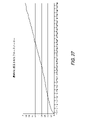
本発明の別の態様によれば、ハウジングと、電源と、ハウジングに配置されたモータと、モータを作動させるためのスイッチと、モータの電圧を取得し、電圧とパーカッシブマッサージ機器によって加えられる力とを関連付けるルックアップテーブルを生成し、かつ、ルックアップテーブルを使用して、取得した電圧に対応する力の大きさを表示するように構成されたコントローラと、を有する、フォースメーターを有するパーカッシブマッサージ機器を提供する。好適な実施形態では、パーカッシブマッサージ機器によって加えられるように構成された力の最大の大きさを決定し、電源からパーカッシブマッサージ機器に印加されるように構成された電圧の最大の大きさを決定し、力の最大の大きさを均等の力の増分に分割し、かつ、電圧の最大の大きさを均等の電圧の増分に分割することによってルックアップテーブルを生成する。均等の力の増分の数及び均等の電圧の増分の数は同一である。好適には、パーカッシブマッサージ機器は、電池パックと、パーカッシブマッサージ機器によって加えられる力の量を表現するように構成されたディスプレイと、を更に有する。好適な実施形態では、ディスプレイは、一連のLEDを有する。好適な実施形態では、パーカッシブマッサージ機器は、有機発光ダイオードスクリーンを有する。 According to another aspect of the invention, the housing, the power supply, the motor located in the housing, the switch for operating the motor, the voltage of the motor, the voltage and the force applied by the percussive massage device. A percussive massage device with a force meter, with a controller configured to generate a lookup table to associate with, and to use the lookup table to display the magnitude of the force corresponding to the acquired voltage. I will provide a. In a preferred embodiment, the maximum magnitude of the force configured to be applied by the percussive massage device is determined and the maximum magnitude of the voltage configured to be applied from the power source to the percussive massage device is determined. , Generate a lookup table by dividing the maximum magnitude of force into equal force increments and the maximum voltage magnitude into equal voltage increments. The number of equal force increments and the number of equal voltage increments are the same. Preferably, the percussive massage device further comprises a battery pack and a display configured to represent the amount of force applied by the percussive massage device. In a preferred embodiment, the display has a series of LEDs. In a preferred embodiment, the percussive massage device has an organic light emitting diode screen.
好適な実施形態では、モータは、ブラシレス直流(BLDC)モータである。好適には、パーカッシブマッサージ機器は、BLDCモータ及びコントローラに電気的に結合された電圧検出抵抗器を有する。 In a preferred embodiment, the motor is a brushless direct current (BLDC) motor. Preferably, the percussive massage device has a voltage sensing resistor electrically coupled to the BLDC motor and controller.
本発明の別の態様によれば、パーカッシブマッサージ機器の力を表示する方法であって、パーカッシブマッサージ機器のモータの電圧を取得することと、電圧とパーカッシブマッサージ機器によって加えられる力とを関連付けるルックアップテーブルを生成することと、ルックアップテーブルを使用して、取得した電圧に対応する力の大きさを表示することと、を備える方法を提供する。好適には、電圧と力とを関連付けるルックアップテーブルは、線形である。好適には、パーカッシブマッサージ機器によって加えられるように構成された力の最大の大きさを決定し、電源からパーカッシブマッサージ機器に印加されるように構成された電圧の最大の大きさを決定し、力の最大の大きさを均等の力の増分に分割し、かつ、電圧の最大の大きさを均等の電圧の増分に分割することによってルックアップテーブルを生成し、均等の力の増分の数及び均等の電圧の増分の数は同一である。 According to another aspect of the present invention, there is a method of displaying the force of a percussive massage device, which is a lookup that associates the acquisition of the voltage of the motor of the percussive massage device with the voltage applied by the percussive massage device. It provides a way to generate a table and use a lookup table to display the magnitude of the force corresponding to the acquired voltage. Preferably, the look-up table that correlates voltage with force is linear. Preferably, the maximum magnitude of the force configured to be applied by the percussive massage device is determined, the maximum magnitude of the voltage configured to be applied from the power source to the percussive massage device is determined, and the force is determined. Generate a lookup table by dividing the maximum magnitude of the into equal force increments and the maximum voltage magnitude into equal voltage increments, the number and equality of equal force increments. The number of voltage increments is the same.
好適な実施形態では、方法は、パーカッシブマッサージ機器の最大電源電圧を取得することと、最大電源電圧を電圧の最大の大きさに設定することと、電圧の最大の大きさを均等の電圧増分に分割することであって、均等の力の増分の数及び均等の電圧の増分の数は同一であることと、電圧と最大電源電圧によって決定される電圧の範囲に対応するパーカッシブマッサージ機器によって加えられる力とを関連付ける更新されたルックアップテーブルを生成することと、更新されたルックアップテーブルを使用して、電源電圧に対応する較正された力の大きさを表示することと、を有する。好適な実施形態では、方法は、表示された力の大きさから決定される力の大きさにそれぞれ対応する少なくとも二つの電源電圧を取得することと、少なくとも二つの電源電圧のそれぞれに対する外部フォースメーターを使用して、パーカッシブマッサージ機器によって加えられる力を測定することと、電圧と測定された力の大きさに対応するパーカッシブマッサージ機器によって加えられる力とを関連付ける更新されたルックアップテーブルを生成することと、を有する。 In a preferred embodiment, the method is to obtain the maximum power supply voltage of the percussive massage device, set the maximum power supply voltage to the maximum voltage magnitude, and set the maximum voltage magnitude to even voltage increments. By splitting, the number of equal force increments and the number of equal voltage increments are the same and added by a percussive massager that corresponds to the voltage range determined by the voltage and the maximum supply voltage. It has to generate an updated lookup table that associates with the force and to use the updated lookup table to display the magnitude of the calibrated force corresponding to the supply voltage. In a preferred embodiment, the method is to obtain at least two supply voltages corresponding to each of the magnitudes of force determined from the magnitude of the displayed force, and an external force meter for each of the at least two supply voltages. To generate an updated lookup table that correlates the voltage applied by a percussive massage device with the force applied by the percussive massage device corresponding to the magnitude of the measured force. And have.
好適な実施形態では、方法は、更新されたルックアップテーブルを使用して、測定された力の大きさに対応する較正された力の大きさを表示することを有する。好適には、ルックアップテーブルは、パーカッシブマッサージ機器上に表示することができる力の大きさごとに更新される。 In a preferred embodiment, the method comprises using an updated look-up table to display the calibrated force magnitude corresponding to the measured force magnitude. Preferably, the look-up table is updated for each amount of force that can be displayed on the percussive massage device.
本発明の別の態様によれば、パーカッシブマッサージ機器の力を表示する方法であって、パーカッシブマッサージ機器のバッテリーパックの電流の大きさを取得することと、バッテリーパックの電圧の大きさを取得することと、電流の大きさ及びバッテリーパックの電圧の大きさを使用して、電力の大きさを決定することと、電力とパーカッシブマッサージ機器によって加えられる電力の大きさとを関連付けるルックアップテーブルを生成することと、ルックアップテーブルを使用して、取得した電力の大きさに対応する力の大きさを表示することと、を有する方法を提供する。好適な実施形態では、力の大きさは、力の大きさに対応して作動される一連のLEDを利用して表示される。好適には、パーカッシブマッサージ機器に入力される電力の最大の大きさを決定し、パーカッシブマッサージ機器に付加が加えられないときのパーカッシブマッサージ機器の電力の最小の大きさを決定し、電源からパーカッシブマッサージ機器によって加えられるように構成された力の最大の大きさを決定し、電力の最大の大きさを均等の電力の増分に分割し、かつ、力の最大の大きさを均等の力の増分に分割することによってルックアップテーブルを生成する。均等の電力の増分の数及び均等の力の増分の数は同一である。好適には、電力の最大の大きさは、総有効電力から導出された最大有効電力の大きさである。 According to another aspect of the present invention, it is a method of displaying the power of the percussive massage device, and obtains the magnitude of the current of the battery pack of the percussive massage device and the magnitude of the voltage of the battery pack. That and the magnitude of the current and the magnitude of the voltage in the battery pack are used to generate a lookup table that correlates the magnitude of the power with the magnitude of the power applied by the percussive massage device. It provides a way to have, and to use a lookup table to display the magnitude of the force corresponding to the magnitude of the acquired power. In a preferred embodiment, the magnitude of the force is displayed utilizing a series of LEDs that are actuated in response to the magnitude of the force. Preferably, the maximum amount of power input to the percussive massage device is determined, the minimum amount of power of the percussive massage device is determined when no additional power is applied to the percussive massage device, and the percussive massage is performed from the power source. Determines the maximum magnitude of force configured to be applied by the device, divides the maximum magnitude of power into equal power increments, and divides the maximum force into equal force increments. Generate a lookup table by splitting. The number of equal power increments and the number of equal force increments are the same. Preferably, the maximum magnitude of power is the magnitude of the maximum active power derived from the total active power.
好適な実施形態では、方法は、力の大きさにそれぞれ対応するバッテリーパックの電流の測定値及び電圧の測定値を使用して少なくとも二つの力の大きさを決定することを有する。力の大きさは、表示された力の大きさから決定される。少なくとも二つの力の大きさのそれぞれについて、外部フォースメーターを使用して、パーカッシブマッサージ機器によって加えられる力を測定し、電力と測定された力の大きさに対応するパーカッシブマッサージ機器によって加えられる力とを関連付ける更新されたルックアップテーブルを生成する。好適な実施形態では、方法は、更新されたルックアップテーブルを使用して、測定された力の大きさに対応する較正された力の大きさを表示することを有する。好適には、ルックアップテーブルは、パーカッシブマッサージ機器上に表示することができる力の大きさごとに更新される。 In a preferred embodiment, the method comprises determining at least two force magnitudes using battery pack current and voltage measurements, respectively, corresponding to the force magnitude. The magnitude of the force is determined from the magnitude of the displayed force. For each of at least two force magnitudes, an external force meter is used to measure the force applied by the percussive massage device and the force applied by the percussive massage device corresponding to the power and the magnitude of the measured force. Generate an updated lookup table to associate with. In a preferred embodiment, the method comprises using an updated look-up table to display the calibrated force magnitude corresponding to the measured force magnitude. Preferably, the look-up table is updated for each amount of force that can be displayed on the percussive massage device.
ここで論じられる本発明の特徴は、任意のタイプのパーカッシブマッサージ機器で使用できることが理解される。例えば、ここで教示されるフォースメーター及び他の特徴は、米国特許第10,357,425号(425特許)及び米国特許出願第16/675,772号に開示されたパーカッシブマッサージ機器と共に使用することができ、その全体が参照により本明細書に組み込まれる。 It is understood that the features of the invention discussed herein can be used with any type of percussive massage device. For example, the force meter and other features taught herein may be used with the percussive massage device disclosed in US Pat. No. 10,357,425 (425) and US Pat. No. 6,675,772. And is incorporated herein by reference in its entirety.
一実施形態では、非一時的なコンピュータ可読媒体は、プロセッサによって実行されるときに、パーカッシブマッサージ機器のモータの電圧を取得することと、電圧とパーカッシブマッサージ機器によって加えられる力とを関連付けるルックアップテーブルを生成することと、ルックアップテーブルを使用して、取得した電圧に対応する力の大きさを表示することと、を、プロセッサに実行させるソフトウェア命令を格納する。 In one embodiment, the non-temporary computer-readable medium obtains the voltage of the motor of the percussive massage device when executed by the processor, and a lookup table that associates the voltage with the force applied by the percussive massage device. Stores software instructions that cause the processor to generate and use a lookup table to display the magnitude of the force corresponding to the acquired voltage.
一実施形態では、パーカッシブマッサージ機器によって加えられるように構成された力の最大の大きさを決定し、電源からパーカッシブマッサージ機器に印加されるように構成された電圧の最大の大きさを決定し、力の最大の大きさを均等の力の増分に分割し、かつ、電圧の最大の大きさを均等の電圧の増分に分割することによってルックアップテーブルを生成する。一実施形態では、均等の力の増分の数及び均等の電圧の増分の数は同一である。 In one embodiment, the maximum magnitude of the force configured to be applied by the percussive massage device is determined, and the maximum magnitude of the voltage configured to be applied from the power source to the percussive massage device is determined. A lookup table is generated by dividing the maximum magnitude of force into equal force increments and the maximum voltage magnitude into equal voltage increments. In one embodiment, the number of equal force increments and the number of equal voltage increments are the same.
別の実施形態では、非一時的なコンピュータ可読媒体は、プロセッサによって実行されるときに、パーカッシブマッサージ機器の最大電源電圧を取得することと、最大電源電圧を電圧の最大の大きさに設定することと、電圧の最大の大きさを均等の電圧増分に分割することであって、均等の力の増分の数及び均等の電圧の増分の数は同一であることと、電圧と最大電源電圧によって決定される電圧の範囲に対応するパーカッシブマッサージ機器によって加えられる力とを関連付ける更新されたルックアップテーブルを生成することと、更新されたルックアップテーブルを使用して、電源電圧に対応する較正された力の大きさを表示することと、を、プロセッサに実行させるソフトウェア命令を格納する。 In another embodiment, the non-temporary computer readable medium obtains the maximum power supply voltage of the percussive massage device and sets the maximum power supply voltage to the maximum magnitude of the voltage when executed by the processor. And, by dividing the maximum magnitude of the voltage into equal voltage increments, the number of equal force increments and the number of equal voltage increments are the same, determined by the voltage and the maximum power supply voltage. Generate an updated lookup table that correlates with the force applied by the percussive massage device corresponding to the voltage range to be applied, and use the updated lookup table to calibrate the force corresponding to the supply voltage. Displays the size of and stores software instructions that cause the processor to execute.
別の実施形態では、非一時的なコンピュータ可読媒体は、プロセッサによって実行されるときに、表示された力の大きさから決定される力の大きさにそれぞれ対応する少なくとも二つの電源電圧を取得することと、少なくとも二つの電源電圧のそれぞれに対する外部フォースメーターを使用して、パーカッシブマッサージ機器によって加えられる力を測定することと、電圧と測定された力の大きさに対応するパーカッシブマッサージ機器によって加えられる力とを関連付ける更新されたルックアップテーブルを生成することと、を、プロセッサに実行させるソフトウェア命令を格納する。 In another embodiment, the non-temporary computer-readable medium, when run by the processor, acquires at least two supply voltages corresponding to each of the magnitudes of force determined by the magnitude of the displayed force. And to measure the force applied by the percussive massage device using an external force meter for each of at least two power supply voltages, and to be applied by the percussive massage device corresponding to the voltage and the magnitude of the measured force. Stores software instructions that cause the processor to generate an updated lookup table that associates with the force.
一実施形態では、非一時的なコンピュータ可読媒体は、プロセッサによって実行されるときに、パーカッシブマッサージ機器のバッテリーパックの電流の大きさを取得することと、バッテリーパックの電圧の大きさを取得することと、電流の大きさ及びバッテリーパックの電圧の大きさを使用して、電力の大きさを決定することと、電力とパーカッシブマッサージ機器によって加えられる電力の大きさとを関連付けるルックアップテーブルを生成することと、ルックアップテーブルを使用して、取得した電力の大きさに対応する力の大きさを表示することと、を、プロセッサに実行させるソフトウェア命令を格納する。 In one embodiment, the non-temporary computer-readable medium obtains the magnitude of the current in the battery pack of the percussive massage device and the magnitude of the voltage in the battery pack when run by the processor. And, using the magnitude of the current and the magnitude of the voltage in the battery pack to determine the magnitude of the power and generate a lookup table that correlates the magnitude of the power with the magnitude of the power applied by the percussive massage device. It uses a lookup table to display the magnitude of the force corresponding to the magnitude of the acquired power, and stores the software instructions that cause the processor to execute.
一実施形態では、非一時的なコンピュータ可読媒体は、プロセッサによって実行されるときに、力の大きさにそれぞれ対応するバッテリーパックの電流の測定値及び電圧の測定値を使用して、表示された力の大きさから決定される少なくとも二つの力の大きさを決定することと、少なくとも二つの力の大きさのそれぞれについて、外部フォースメーターを使用して、パーカッシブマッサージ機器によって加えられる力を測定することと、電力と測定された力の大きさに対応するパーカッシブマッサージ機器によって加えられる力とを関連付ける更新されたルックアップテーブルを生成することと、を、プロセッサに実行させるソフトウェア命令を格納する。 In one embodiment, the non-temporary computer-readable medium is displayed using the current and voltage measurements of the battery pack, respectively, corresponding to the magnitude of the force when run by the processor. Determine the magnitude of at least two forces determined by the magnitude of the force, and measure the force applied by the percussive massage device using an external force meter for each of the magnitudes of the two forces. Stores software instructions that cause the processor to perform an updated lookup table that associates that with the force applied by the percussive massage device corresponding to the magnitude of the force measured.
好適な実施形態では、一実施形態では、電源からの電力を運動に変換する。いくつかの実施形態では、モータは、電気モータである。電気モータは、ブラシ付きモータ、ブラシレスモータ、直流(DC)モータ、交流(AC)モータ、機械的整流モータ、電子整流モータ又は外部整流モータを含むがそれに限定されない当該技術分野で知られている任意のタイプの電気モータであってもよい。 In a preferred embodiment, in one embodiment, the power from the power source is converted into motion. In some embodiments, the motor is an electric motor. Electric motors include, but are not limited to, brushed motors, brushless motors, DC (DC) motors, AC (AC) motors, mechanical rectifying motors, electronic rectifying motors or external rectifying motors. It may be an electric motor of the type.
いくつかの実施形態では、作動された出力又は出力シャフトは、約65Hzの速度で往復運動する。作動された出力は、いくつかの実施形態では、50Hzを超える速度で往復運動する。往復運動治療装置は、いくつかの実施形態では、50Hzから80Hzの範囲の速度で往復運動を提供する。いくつかの実施形態では、作動出力は、50Hzから80Hzの間の最大の関節運動速度(articulation rate)を有する。別の実施形態では、作動出力は、30Hzから80Hzの間の関節運動速度を有する。特定の実施形態では、作動出力は、約37Hzの関節運動速度を有する。一実施形態では、作動出力は、約60Hzの関節運動速度を有する。好適な実施形態では、作動出力は、約15Hzから約100Hzの間の周波数で関節運動又は往復運動する。更に好適な実施形態では、作動出力は、約25Hzから約48Hzの間の周波数で関節運動又は往復運動する。最も好適な実施形態では、作動出力は、約33Hzから約42Hzの間の周波数で関節運動又は往復運動する。指定された範囲内の任意の選択された範囲は、本発明の範囲内である。 In some embodiments, the actuated output or output shaft reciprocates at a speed of about 65 Hz. The activated output reciprocates at speeds above 50 Hz in some embodiments. The reciprocating motion therapy device, in some embodiments, provides reciprocating motion at speeds in the range of 50 Hz to 80 Hz. In some embodiments, the working output has a maximum articulation rate between 50 Hz and 80 Hz. In another embodiment, the working output has a range of motion between 30 Hz and 80 Hz. In certain embodiments, the working output has a range of motion of about 37 Hz. In one embodiment, the working output has a range of motion of about 60 Hz. In a preferred embodiment, the working output is a range of motion or reciprocating motion at a frequency between about 15 Hz and about 100 Hz. In a more preferred embodiment, the working output is a range of motion or reciprocating motion at a frequency between about 25 Hz and about 48 Hz. In the most preferred embodiment, the working output is a range of motion or reciprocating motion at a frequency between about 33 Hz and about 42 Hz. Any selected range within the specified range is within the scope of the invention.
作動出力は、所定の範囲の往復運動を介して移動してもよい。例えば、作動出力は、0.5インチの振幅を有するように構成されてもよい。別の実施形態では、作動出力は、4分の1インチの振幅を有するように構成されてもよい。当業者によって理解されるように、作動出力は、治療的に有益であるとみなされる任意の振幅を有するように構成されてもよい。 The working output may move via a range of reciprocating motions. For example, the working output may be configured to have an amplitude of 0.5 inch. In another embodiment, the working output may be configured to have an amplitude of a quarter inch. As will be appreciated by those of skill in the art, the working output may be configured to have any amplitude that is considered therapeutically beneficial.
いくつかの実施形態では、作動出力は、可変範囲の往復運動によって調整可能であってもよい。例えば、往復運動する治療装置は、往復運動の振幅を4分の1インチから最大1インチの範囲まで調整するための入力を有してもよい。好適な実施形態では、作動出力は、約0.15インチから約1.0インチの間の振幅で移動する。更に好適な実施形態では、作動出力は、約0.23インチから約0.70インチの間の周波数で関節運動又は往復運動する。最も好適な実施形態では、作動出力は、関節運動する又は約0.35インチから約0.65インチの間の周波数で往復する。指定された範囲内の任意の選択された範囲は、本発明の範囲内である。 In some embodiments, the working output may be adjustable by a variable range of reciprocating motion. For example, a reciprocating treatment device may have an input for adjusting the amplitude of the reciprocating motion from a quarter inch to a maximum of one inch. In a preferred embodiment, the working output travels with an amplitude between about 0.15 inch and about 1.0 inch. In a more preferred embodiment, the working output is range of motion or reciprocating at a frequency between about 0.23 inches and about 0.70 inches. In the most preferred embodiment, the working output moves joints or reciprocates at a frequency between about 0.35 inches and about 0.65 inches. Any selected range within the specified range is within the scope of the invention.
組み合わされた周波数及び振幅の範囲内で機器が最も効果的に動作することが理解される。本発明を開発するとき、本発明者は、周波数及び振幅が機器の上に記載された範囲を超える場合に痛みを引き起こす可能性があり、範囲を下回る場合には機器は効果がなくて効果的な治療的緩和又はマッサージを提供しないと判断した。開示された周波数と振幅の範囲の組合せ内で機器が動作する場合にのみ、機器は、機器の対象となる筋肉に対する効率的かつ有益な治療を行う。 It is understood that the equipment operates most effectively within the range of combined frequencies and amplitudes. When developing the invention, the inventor may cause pain if the frequency and amplitude exceed the range described above the device, and below the range the device is ineffective and effective. It was determined not to provide any therapeutic relief or massage. Only if the device operates within the disclosed frequency and amplitude range combination will the device provide efficient and beneficial treatment for the muscle of interest of the device.
特定の実施形態では、往復運動治療装置は、電力入力で提供される電力の様々なレベルに応じて作動出力の関節運動速度を調整する一つ又は複数の構成要素を有する。例えば、往復運動治療装置は、入力電圧の範囲に亘ってモータに略一定の電圧を供給するための電圧調整器(図示せず)を有してもよい。別の実施形態では、モータに供給される電流を調整してもよい。いくつかの実施形態では、往復運動する治療装置の動作は、入力電圧がプリセット値を下回ることに応答して制限されてもよい。 In certain embodiments, the reciprocating motion therapy device has one or more components that adjust the joint motion rate of the working output according to various levels of power provided at the power input. For example, the reciprocating motion therapy device may have a voltage regulator (not shown) for supplying a substantially constant voltage to the motor over a range of input voltages. In another embodiment, the current supplied to the motor may be adjusted. In some embodiments, the operation of the reciprocating therapy device may be limited in response to the input voltage falling below the preset value.
好適な実施形態では、パーカッシブマッサージ機器は、ブラシレスモータを有する。ブラシレスモータは、ギアを有さず、ギア付きモータよりも静かであることが理解される。 In a preferred embodiment, the percussive massage device has a brushless motor. It is understood that brushless motors have no gears and are quieter than geared motors.
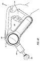
機器は、ピンによってモータに直接接続されているプッシュロッド又はシャフトを有する。好適な実施形態では、プッシュロッドは、L字型である又は円弧形状を有する。好適には、プッシュロッドがピンに接続される点は、プッシュロッド(及びマッサージアタッチメント)の遠位端40が移動する往復経路からオフセットされている。この機能は、円弧又はL字型によって提供される。モータを機器の中央又はその近くに配置することができない場合にはモータをオフセットしてシャフトを中央に保持する(するとともに配置)ための突起が必要になるためにモータを機器の中央又はその近くに配置することができるようにプッシュロッド14が力を少なくとも部分的に斜めに又は垂直ではなくその形状に沿って弧状に伝達できるようにプッシュロッドが設計されていることを理解すべきである。円弧は、プッシュロッドがモータと密接なクリアランスを有することを可能にし、外部ハウジングを同様の従来技術の機器よりも小さくすることを可能にし、したがって、機器の側面を更に低くすることができる。好適には、二つのベアリングは、斜め方向の力に対抗するためにモータに接続するプッシュロッドの近位端に含まれ、プッシュロッドが移動するとともにモータに接触するのを防止する。プッシュロッドの近位端に含まれ、それは、斜め方向の力を打ち消すためにモータに接続され、プッシュロッドがモータを動かして接触するのを防止する。
The device has a push rod or shaft that is directly connected to the motor by a pin. In a preferred embodiment, the push rod is L-shaped or has an arc shape. Preferably, the point where the push rod is connected to the pin is offset from the reciprocating path through which the
好適な実施形態では、機器は、停止、始動、作動等のためのタッチスクリーンを有する。タッチスクリーンは、他の機能を有してもよい。好適には、機器は、ユーザが様々な機能を介してスクロール又はナビゲートすることを可能にするためにタッチスクリーン/オンオフボタンの近くに配置されたサムホイール又はローリングボタンを有する。好適には、機器は、可変振幅又はストロークも含む。例えば、ストロークは、約8~16mmの間で変更することができる又は変更させることができる。 In a preferred embodiment, the device has a touch screen for stopping, starting, activating, and the like. The touch screen may have other functions. Preferably, the device has a thumbwheel or rolling button located near the touch screen / on / off button to allow the user to scroll or navigate through various functions. Preferably, the instrument also includes variable amplitude or stroke. For example, the stroke can be changed or changed between about 8 and 16 mm.
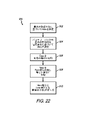
好適な実施形態では、機器は、電話、時計又はタブレット(又は任意のコンピュータ)のようなモバイル機器で実行されるアプリ又はソフトウェアに関連付けられるとともにそれによって操作することができる。アプリは、ブルートゥース(登録商標)又は他の接続プロトコルを介して機器に接続することができる。アプリは、次の機能のいずれか又は全てを有することができる。さらに、ここで説明する機能のいずれも、機器のタッチスクリーン/スクロールホイール又は(一つ以上の)ボタン機能に直接追加することができる。ユーザが歩く場合又は機器から離れすぎている場合、機器は機能しない又は作動しない。機器は、アプリ及び機器のタッチスクリーン又はボタンを使用してオンとオフを切り替えることができる。アプリは、(例えば、1750~3000RPMの間のどこでも)可変速度を制御することができる。機器を所定の時間後に停止させるためにタイマーを実装することができる。アプリは、それに関連付けられた様々な治療プロトコルを有することもできる。これにより、ユーザは、作動したいプロトコル又は身体の領域を選択することができる。プロトコルの開始が選択されると、機器は、ルーチンを実行する。例えば、機器は、第1の期間に第1のRPMで動作した後に第2の期間に第2のRPMで動作してもよい及び/又は第1の期間に第1の振幅で動作した後に第2の振幅で動作してもよい。ルーチンは、新たな身体の部分に移動することをユーザに知らせるためのプロンプト(例えば、触覚フィードバック)も有することができる。これらのルーチン又は治療は、回復、血流の増加、パフォーマンス等に関連させることができるとともにそれぞれが事前にプログラムされたルーチン又はプロトコルを有することができる。ルーチンは、治療構造(AmpBITS)又はアーム若しくは回転ヘッドの位置を切り替えることをユーザに促すことができる又は指示することができる。プロンプトは、音、触覚フィードバック(例えば、機器又はモバイル機器の振動)、アプリ又はタッチスクリーンのテキストによる指示等を有してもよい。例えば、アプリは、位置2にアームを有するボール治療構造から始めるようにユーザに指示してもよい。次に、ユーザは、スタートを押し、機器は、第1の周波数で所定の時間実行する。次に、アプリ又は機器は、ルーチンの次のステップを開始することをユーザに促し、コーン治療構造に変更するとともにアームを位置1に配置することをユーザに指示する。ユーザは、もう一度スタートを押し、機器は、第2の周波数で所定の時間実行する。
In a preferred embodiment, the device can be associated with and operated by an app or software running on a mobile device such as a telephone, watch or tablet (or any computer). The app can connect to the device via Bluetooth® or other connection protocols. The app can have any or all of the following features: In addition, any of the features described herein can be added directly to the device's touch screen / scroll wheel or (one or more) button features. If the user walks or is too far from the device, the device will not work or will not work. The device can be turned on and off using the app and the device's touch screen or buttons. The app can control variable speeds (eg, anywhere between 1750 and 3000 RPM). A timer can be implemented to stop the device after a predetermined time. The app can also have various treatment protocols associated with it. This allows the user to select the protocol or area of the body that he or she wants to operate. When the start of the protocol is selected, the instrument executes the routine. For example, the device may operate in a first RPM after operating in a first period and then in a second RPM and / or after operating in a first amplitude in a first period. It may operate with an amplitude of 2. The routine can also have a prompt (eg, tactile feedback) to inform the user to move to a new body part. These routines or treatments can be associated with recovery, increased blood flow, performance, etc. and each can have a pre-programmed routine or protocol. The routine can prompt or instruct the user to switch the position of the therapeutic structure (AmpBITS) or arm or rotating head. Prompts may include sound, haptic feedback (eg, vibration of a device or mobile device), textual instructions on an app or touch screen, and the like. For example, the app may instruct the user to start with a ball therapy structure having an arm at
好適な実施形態では、アプリは、近距離無線通信(“NFC”)機能又は上記のルーチンのような所定の情報を表示することをアプリに促すバーコード又はQRコード(登録商標)のような識別子のスキャンがアプリを搭載したユーザのモバイル機器によって可能になる他の機能を含む。使用中、ユーザは、モバイル機器をタップすること又はジム装置のNFCタグの近くに配置すること(又はQRコード(登録商標)をスキャンすること)ができ、アプリは、装置によって、機器を使用するためにカスタマイズされた指示、コンテンツ又はレッスンを表示する。例えば、トレッドミルでは、ユーザがQRコード(登録商標)又はNFCタグをスキャンすると、アプリは、ユーザがトレッドミルを使用しようとしていることを認識する。アプリは、トレッドミルと組み合わせて機器を使用する方法についての指示を提供することができ、かつ、トレッドミルを使用するための事前にプログラムされたルーチンを開始することができる。例えば、左側のクワッドから開始するようにユーザを指示することができる。次に、所定の時間(例えば、15秒)後、機器は、振動する又は他の触覚フィードバックを提供する。次に、ユーザは、左側のクワッド(left quad)に切り替え、所定の時間が経過すると、機器が再び振動する。その後、ユーザは、トレッドミルの使用を開始することができる。任意のルーチンは、本発明の範囲内にある。一実施形態では、機器及び/又はアプリ(すなわち、アプリを含むモバイル機器)は、ジム機器(例えば、トレッドミル)と(ブルートゥース(登録商標)等を介して)通信することもできる。 In a preferred embodiment, the app is an identifier such as a barcode or QR code® that prompts the app to display certain information such as near field communication (“NFC”) functionality or routines described above. Includes other features that can be scanned by the user's mobile device with the app. During use, the user can tap the mobile device or place it near the NFC tag of the gym device (or scan the QR code®) and the app will use the device by the device. View instructions, content or lessons customized for you. For example, on a treadmill, when the user scans a QR code® or NFC tag, the app recognizes that the user is trying to use the treadmill. The app can provide instructions on how to use the device in combination with the treadmill and can initiate pre-programmed routines for using the treadmill. For example, you can instruct the user to start with the quad on the left. The device then vibrates or provides other tactile feedback after a predetermined time (eg, 15 seconds). The user then switches to the left quad, and after a predetermined period of time, the device vibrates again. The user can then start using the treadmill. Any routine is within the scope of the invention. In one embodiment, the device and / or the app (ie, the mobile device including the app) can also communicate with a gym device (eg, a treadmill) (via Bluetooth®, etc.).
機器は、ユーザに加えている力の量を知らせるためにトルク又はフォースメーターを有してもよい。フォースメーターに関連付けられたディスプレイは、筋肉に加えられている力の量を表示する。フォースメーターは、更に正確で効果的な治療を可能にする。機器は、トルク測定センサ及びディスプレイを有する。機器が使用されている筋肉及びユーザが得ようとしている利点(準備、実行、回復)に応じて、適用する必要のある力は異なる。トルクセンサを有することによって、ユーザは、更に正確で個別化された治療を受けることができる。アプリ及びタッチスクリーンは、力の情報をユーザに提供することができる。フォースメーターをルーチンに統合することができ、ユーザは、圧力が大きすぎるか小さすぎるかについてフィードバックを提供することができる。機器は、ユーザの筋肉の温度を決定するとともに機器及び/又はアプリにフィードバックを提供することができる熱センサ又は温度計を有してもよい。触覚フィードバックは、過度の圧力又は力に対するフィードバックを提供することもできる。 The device may have a torque or force meter to inform the user of the amount of force applied. A display associated with the force meter shows the amount of force applied to the muscles. The force meter enables more accurate and effective treatment. The device has a torque measurement sensor and a display. Depending on the muscles in which the device is used and the benefits the user is trying to obtain (preparation, execution, recovery), the forces that need to be applied will vary. Having a torque sensor allows the user to receive more accurate and personalized treatment. The app and touch screen can provide power information to the user. The force meter can be integrated into the routine and the user can provide feedback on whether the pressure is too high or too low. The device may have a thermal sensor or thermometer that can determine the temperature of the user's muscles and provide feedback to the device and / or the app. Tactile feedback can also provide feedback on excessive pressure or force.
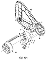
好適な実施形態では、パーカッシブマッサージ機器は、ブラシレスモータをハウジングに取り付けるとともにモータが動作するときにモータからハウジングに力を分配するためのモータマウントを有する。モータは、モータマウントの第1の側に固定され、モータマウントの第2の側又は反対側はハウジングに固定される。モータマウントは、モータをハウジングから離間させるとともにプッシュロッド及び関連する構成要素(カウンターウェイト等)が往復する往復空間を規定する複数のアームを有する。ネジ留め具は、モータマウントをハウジングに接続する。好適な実施形態では、減衰部材又は脚は、ねじ付きファスナーのシャフトに受け入れられる。減衰部材はそれぞれ、その中に定義された環状スロットを有する。環状スロットは、ハウジングを受け入れる。これにより、ねじ付きファスナーがハウジングに直接接触するのを防止し、振動による音を低減する。ねじ付きファスナーは、アームの端にあるタブの開口部に受け入れられる。 In a preferred embodiment, the percussive massage device has a motor mount for mounting the brushless motor to the housing and distributing force from the motor to the housing as the motor operates. The motor is fixed to the first side of the motor mount and the second or opposite side of the motor mount is fixed to the housing. The motor mount has a plurality of arms that separate the motor from the housing and define a reciprocating space for the push rod and related components (counterweights, etc.) to reciprocate. Screw fasteners connect the motor mount to the housing. In a preferred embodiment, the damping member or leg is accepted on the shaft of the threaded fastener. Each damping member has an annular slot defined therein. The annular slot accepts the housing. This prevents the threaded fasteners from coming into direct contact with the housing and reduces vibration noise. Threaded fasteners are accepted into the tab openings at the ends of the arm.
好適な実施形態では、モータは、メインハウジングで回転可能なモータハウジングに収容される。モータハウジングは、基本的には、関連する実施形態のギアボックスハウジングと同等である。好適な実施形態では、一方の側でモータを露出させるとともに他方の側でモータマウントを露出させる向かい合った開口がモータハウジングの外側にある。開口は、モータに換気を提供し、モータマウントをメインハウジングに直接接続できるようにする。 In a preferred embodiment, the motor is housed in a motor housing that is rotatable in the main housing. The motor housing is basically equivalent to the gearbox housing of the related embodiment. In a preferred embodiment, there are facing openings on the outside of the motor housing that expose the motor on one side and the motor mount on the other side. The openings provide ventilation to the motor and allow the motor mount to connect directly to the main housing.
好適な実施形態では、機器は、機器を操作するためのタッチスクリーン及びボタンを有する。例えば、機器は、タッチスクリーン、機器のオンとオフを切り替えるための中央ボタン並びに(例えば、ここで説明するプリセット処理のための)左右のスクロール及び(例えば、速度又は周波数を制御するための)上下のスクロールを行う機能を提供するリング/ロッカーボタンを有することができる。画面を非タッチスクリーンにすることもできる。 In a preferred embodiment, the device has a touch screen and buttons for operating the device. For example, the device may have a touch screen, a center button to turn the device on and off, and left / right scrolling (eg, for preset processing described herein) and up / down (eg, for controlling speed or frequency). Can have a ring / rocker button that provides the ability to scroll. The screen can also be a non-touch screen.
別の好適な実施形態では、ここで教示される機器のいずれかは、振幅を変化させる能力を有することができ、したがって、ユーザの用途又はニーズに応じて更に長い又は更に短いストロークを提供する。振幅変動は、ここで論じられるルーチン又はプリセットの一部となることもできる。例えば、機器は、コネクタの偏心を(例えば、4mmから8mmの間で)変更することを可能にする機械的スイッチを有することができる。機構は、プッシュボタン及びスライダーを有することができる。ピン構造は、ロック位置に戻すバネを有する。 In another preferred embodiment, any of the instruments taught herein can have the ability to vary amplitude and thus provide longer or shorter strokes depending on the user's application or needs. Amplitude variation can also be part of the routines or presets discussed here. For example, the device can have a mechanical switch that allows the eccentricity of the connector to be changed (eg, between 4 mm and 8 mm). The mechanism can have a push button and a slider. The pin structure has a spring that returns it to the locked position.
好適な実施形態では、機器は、停止、開始、動作等のためのタッチスクリーンを有する。タッチスクリーンは、他の機能を有することもできる。好適には、機器は、ユーザが異なる機能をスクロール又はナビゲートできるようにするためにタッチスクリーン/オンオフボタンの近くに配置されたサムホイール又はローリングボタンを有する。 In a preferred embodiment, the device has a touch screen for stopping, starting, moving, and the like. The touch screen can also have other functions. Preferably, the device has a thumbwheel or rolling button located near the touch screen / on / off buttons to allow the user to scroll or navigate different functions.
本発明を、以下の添付の図面を参照することによって更に容易に理解することができる。 The present invention can be more easily understood by reference to the accompanying drawings below.
同様の番号は、図面の複数の図に亘って同様のパーツを示す。 Similar numbers indicate similar parts across multiple figures in the drawing.
以下の説明及び図面は例示的なものであり、限定的なものとして解釈されるべきではない。本開示の完全な理解を提供するために、多数の特定の詳細を説明する。しかしながら、特定の例では、説明を曖昧にすることを避けるために、周知の又は従来の詳細を説明しない。本開示の一実施形態についての言及は、必ずしも同一の実施形態についての言及でなくてもよく、そのような言及は、実施形態の少なくとも一つを意味する。 The following description and drawings are exemplary and should not be construed as limiting. A number of specific details are described to provide a complete understanding of this disclosure. However, certain examples do not provide well-known or conventional details to avoid obscuring the description. References to an embodiment of the present disclosure do not necessarily have to refer to the same embodiment, such reference means at least one of the embodiments.
本明細書における「一実施形態」又は「実施形態」についての言及は、実施形態に関連して説明される特定の特徴、構造又は特性が開示の少なくとも一つの実施形態に含まれることを意味する。本明細書の様々な場所での「一実施形態において」という句の出現は、必ずしも全てが同じ実施形態を指すわけではなく、他の実施形態を相互に排除する別個の又は代替の実施形態でもない。さらに、いくつかの実施形態によって示されるとともに他の実施形態によって示されない可能性がある様々な特徴を説明する。同様に、いくつかの実施形態の要件であってもよいが、他の実施形態ではない様々な要件を説明する。 Reference to "one embodiment" or "embodiment" herein means that the particular features, structures or properties described in connection with the embodiment are included in at least one embodiment of the disclosure. .. The appearance of the phrase "in one embodiment" in various places herein does not necessarily refer to the same embodiment, but may be separate or alternative embodiments that mutually exclude other embodiments. do not have. In addition, various features that may be shown by some embodiments but not by others will be described. Similarly, various requirements that may be requirements of some embodiments but not of others will be described.
本明細書で使用される用語は、一般的には、本技術において、本開示の文脈内で及び各用語が使用される特定の文脈においてそれらの通常の意味を有する。開示を説明するために使用される特定の用語を、開示の説明に関して施術者(practitioner)に追加のガイダンスを提供するために、以下で又は本明細書の他の場所で説明する。便宜上、特定の用語を、例えば、斜体や引用符を使用して強調する場合がある。強調の使用は、用語の範囲及び意味に影響を及ぼさず、用語の範囲及び意味は、強調されているか否かに関係なく同一の文脈で同一である。同一のことが複数の方法で言えることが理解される。 The terms used herein generally have their usual meaning in the context of the present disclosure and in the particular context in which each term is used. Specific terms used to describe the disclosure will be described below or elsewhere herein to provide additional guidance to the practitioner regarding the description of the disclosure. For convenience, certain terms may be emphasized, for example, using italics or quotation marks. The use of emphasis does not affect the scope and meaning of the term, and the scope and meaning of the term is the same in the same context whether emphasized or not. It is understood that the same thing can be said in multiple ways.
したがって、ここで論じられる用語のいずれか一つ又は複数について、代替の言語及び同義語を使用してもよい。ここで用語が詳しく説明されているか否かに関係なく、特別な意味はない。特定の用語についての同義語を提供する。一つ以上の同義語の説明は、他の同義語の使用を排除するものではない。ここで論じられる任意の用語の例を含む本明細書の任意の場所での例の使用は、例示にすぎず、開示又は例示された用語の範囲及び意味を更に限定することを意図するものではない。同様に、本開示は、本明細書で与えられる様々な実施形態に限定されない。 Therefore, alternative languages and synonyms may be used for any one or more of the terms discussed herein. There is no special meaning here, whether or not the terms are explained in detail. Provide synonyms for specific terms. The description of one or more synonyms does not preclude the use of other synonyms. The use of examples anywhere in the specification, including examples of any term discussed herein, is merely exemplary and is not intended to further limit the scope and meaning of the disclosed or exemplified term. do not have. Similarly, the present disclosure is not limited to the various embodiments given herein.
開示の範囲を更に限定することを意図することなく、本開示の実施形態による器具、装置、方法及びそれらに関連する結果の例を以下に示す。読者の便宜のために、例においてタイトル又はサブタイトルを使用することがあり、これが開示の範囲を限定するものではないことに留意されたい。別段の定義がない限り、ここで使用される全ての技術用語及び科学用語は、本開示に関係する当業者によって一般に理解されるのと同一の意味を有する。矛盾が生じた場合は、定義を含む本文書が優先される。 Without intending to further limit the scope of the disclosure, examples of instruments, devices, methods and related results according to the embodiments of the present disclosure are shown below. Please note that for the convenience of the reader, titles or subtitles may be used in the examples and this does not limit the scope of disclosure. Unless otherwise defined, all technical and scientific terms used herein have the same meaning as commonly understood by one of ordinary skill in the art relating to this disclosure. In the event of a conflict, this document containing the definition will prevail.
ここで使用される「前方」、「後方」、「上側」、「下側」、「側」、「短い」、「長い」、「上」、「下」及び「後」のような用語が単に説明を容易にするためのものであるとともに図に示されるような構成要素の向きを指すことを理解されたい。本明細書に記載の構成要素の任意の向きが本発明の範囲内であることを理解すべきである。 Terms used herein such as "front", "rear", "upper", "lower", "side", "short", "long", "upper", "lower" and "rear" It should be understood that it is merely for ease of explanation and refers to the orientation of the components as shown in the figure. It should be understood that any orientation of the components described herein is within the scope of the invention.
多くの実施形態をここに記載するが、記載されている実施形態のうちの少なくともいくつかは、往復運動する治療装置のための器具、システム及び方法を提供する。 Many embodiments are described herein, but at least some of the described embodiments provide instruments, systems and methods for reciprocating therapeutic devices.
図1~10は、充電式電池(及び交換可能又は取り外し可能な電池)114を有するパーカッシブマッサージ機器212の実施形態を示す。機器212は商業的にはG3PROと称される。図1~1Aに示すように、好適な実施形態では、パーカッシブマッサージ機器212は、協力して中央又はハンドル開口を規定する(ここでは第1のハンドル部分、第2のハンドル部分及び第3のハンドル部分と称する)三つのハンドル部分を有する。ハンドル部分の全ては、人が機器を利用するために特定のハンドル部分を握ることができるように構成されるのに十分な長さである。様々なハンドル部分をつかむ機能により、人は、(自分の身体で機器を使用するときに)様々な身体の部分で様々な角度から機器を使用でき、したがって、背中のような身体の部分に到達することができ、これは、三つのハンドル部分なしでは不可能である。
FIGS. 1-10 show embodiments of a
図1に示すように、第1のハンドル部分143は、第1のハンドル部分軸A1を規定し、第2のハンドル部分145は、第2のハンドル部分軸A2を規定し、第3のハンドル部分147は、協調して第3のハンドル部分軸A3を規定し、協力して三角形を形成する。好適な実施形態では、電池114は、第2のハンドル部分145に収容され、モータ106は、第3のハンドル部分147に収容される。
As shown in FIG. 1, the
図3~5は、様々なハンドル部分を握っているユーザの手を示す。図3~5に示すように、第1のハンドル部分、第2のハンドル部分及び第3のハンドル部分のそれぞれの長さは、大きな手を持つ人がハンドル開口を通って延在する少なくとも3~4本の指で各ハンドル部分を快適に握ることができるように十分に長い。好適な実施形態では、第1のハンドル部分143は、内縁143aを有し、第2のハンドル部分145は、内縁145aを有し、第3のハンドル部分147は、内縁147aを有し、これらの全ては、協力してハンドル開口149を少なくとも部分的に規定する。図1に示すように、好適な実施形態では、第1のハンドル部分143は、第1のハンドル部分の内縁143aと第3のハンドル部分147の内縁147aの間に延在するとともに少なくとも部分的にハンドル開口部149を規定する指表面151aを有する指突起151を有する。図3に示すように、使用中、ユーザは、人差し指を指表面151aに置くことができる。指突起及び指表面は、ユーザが人差し指を表面に置くときにユーザが機器の使用を制御するとともに快適にすることを助けるようにフィードバックポイント又はサポート表面を提供する。好適な実施形態では、指表面151aの少なくとも一部は、図1に示すように(丸みを帯びているハンドル開口149の他の「角」とは対照的に)真っ直ぐである。
3-5 show the hands of the user holding various handle parts. As shown in FIGS. 3-5, the lengths of the first handle portion, the second handle portion and the third handle portion are at least 3 to which a person with a large hand extends through the handle opening. Long enough to comfortably grip each handle with four fingers. In a preferred embodiment, the
図1Aは、ハンドル開口149の内面の好適な寸法を示す。内面が一連の平坦な曲面を含むことが理解される。H1は、第1のハンドル部143の内縁143aの寸法(第1のハンドル部の長さ)である。H2は、第2のハンドル部145の内縁145aの寸法(第2のハンドル部の長さ)である。H3は、第3のハンドル部147の内縁147aの寸法(第3のハンドル部の長さ)である。H4は、指の表面151aの寸法(指の突起の長さ)である。R1は、内縁143aと内縁145aの間の半径の寸法であり、R2は、内縁145aと内縁147aの間の半径の寸法である。好適な実施形態では、H1は、約94mmであり、H2は、約66mmであり、H3は、約96mmであり、H4は、約12mmであり、R1は、約6.5mmであり、R2は、約6.5mmであり、それは、約10.2mmの弧の長さを提供する。ここの文脈において、「約」は5mm以内である。好適な実施形態では、ハンドル開口の内縁の長さは、約289mmである。ハンドル開口の内縁の長さを、H1、H2、H3、H4、R1及びR2の任意の組み合わせで約260mmと約320mmの間にすることができる。95パーセンタイルの男性が機器を利用するためにハンドル開口を通って延在する少なくとも3本、好ましくは4本の指で三つのハンドル部分のいずれかを握ることができるようにこれらの寸法が最適化されることが理解される。表面R1と表面R2のいずれか又は全てが三つの隣接するハンドル部分のいずれかの一部と見なすことができることが理解される。図1及び図1Aに示すように、指面151aが真っ直ぐであり、第1のハンドル部分の内面、第2のハンドル部分の内面、第3のハンドル部分の内面及び指表面が協力して、真っ直ぐな表面のそれぞれの間に半径又は丸みを帯びた縁を有する四辺形を規定する。
FIG. 1A shows suitable dimensions of the inner surface of the
機器212は、(好適には1500RPM及び2400RPMであるがここで教示される任意の速度又は周波数とすることができる)複数の速度設定も有する。さらに、RPMが特定の数として記載されているが、製造公差のために、RPMが使用中に変動する可能性があることが当業者によって理解される。例えば、2400RPMの設定では、RPMは、実際には、2260と2640の間で変動する可能性がある。
The
図6~10は、図1~5及び図11~16に示す処理装置212(208及び210)に含まれる内部構成要素及び外部構成要素のいくつかを示す。図6に示すように、パーカッシブマッサージ機器212は、第1のハウジングハーフ及び第2のハウジングハーフ103から構成されるハウジング101を有する。外側カバー213及び上部カバー215は、タブ105又は他の機構又は取り付け方法(例えば、ねじ山付きファスナー、クリップ、接着剤、音波溶接等)を介して、第1のハウジングハーフ及び第2のハウジングハーフ103に受け入れられるとともに接続される。パーカッシブマッサージ機器212は、タンブールドア217と、電池114と、内部サスペンションリング219と、ギアボックス404を収容する(第1の回転ハウジングハーフ44a及び第2の回転ハウジングハーフ44bを有する)回転ハウジング44と、を有する。
6-10 show some of the internal and external components included in the processing devices 212 (208 and 210) shown in FIGS. 1-5 and 11-16. As shown in FIG. 6, the
図7に示すように、機器は、モータとピニオンシャフト又は(シャフト又はピニオンシャフト116に配置される)シャフトギア117の間に配置されるピニオンカップリングアセンブリ216を有する。ピニオンカップリングアセンブリ216は、半径方向の動きがなくなるとともに振動及び騒音を最小限に抑えてトルクが完全に伝達されるようにモータをギアボックスに結合するために使用される。ピニオンカップリングアセンブリ216は、好適には、三つの別個の構成要素、下側コネクタ218、クロスカップリング220及び上側コネクタ222を有する。好適な実施形態では、下側コネクタ218は、モータシャフト248並びに外向きに延在する第1の下側コネクタアーム及び第2の下側コネクタアーム218cを受け入れる中央開口218bを規定する本体部分218aを有する。上側コネクタ122は、ピニオンシャフト117並びに外向きに延在する第1の上側コネクタアーム及び第2の上側コネクタアーム222cを受け入れる中央開口122bを規定する本体部分222aを有する。好適には、クロスカップリング220は、チャネル220bを規定する半径方向に延在するリブ220aを有する。第1の下側コネクタアーム及び第2の下側コネクタアーム218c並びに第1の上側コネクタアーム及び第2の上側コネクタアーム222cは、半径方向に延在するリブと動作可能に係合するようにチャネル220bに受け入れられるサイズ及び形状である。使用中、モータシャフト248は、ピニオンカップリングアセンブリを回転させ、ピニオンカップリングアセンブリは、ピニオンシャフト117を回転させる。これらの構成要素は、騒音及び振動を低減するために協働する。好適な実施形態では、下側コネクタ及び上側コネクタは、プラスチックによって構成され、クロスカップリングは、エラストマーによって構成される。好適な実施形態では、クロスカップリング220は、強度を維持するとともにトルクを効率的に(大幅なエネルギー散逸なしに)伝達しながらモータによって生成される振動が切り離される硬度を有するゴムによって構成される。しかしながら、材料は、本発明を限定するものではない。
As shown in FIG. 7, the device has a
好適な実施形態では、ピニオンシャフト116は、ベアリング224及び225に受け入れられるとともにそれらに延在する。好適には、ベアリング224は、ボールベアリングを有し(半径方向のサポートを提供する)、ベアリング225は、ニードルベアリングを有する(半径方向のサポートを提供するが更に高い温度に耐えることができる)。ピニオンカップリングアセンブリ216は、モータ106に接続されるとともにモータシャフト248が延在するモータマウント250に収容される。モータマウント250は、図9に示すように、ギアボックスマウント252に接続される。
In a preferred embodiment, the
図7~9に示すように、ギアボックス404は、一実施形態では、ギア部材304と、レシプロケータ又はプッシュロッド230/310と、を有する。好適には、ギア部材304は、そこから延在するシャフト246を有し、そこにレシプロケータ310が接続される。ギアボックス404は、ギア部材304及びレシプロケータ310の取り付け点を提供することができる。ギアボックス404は、ギア部材304及びレシプロケータの動きを特定の方向又は回転軸に制限することができる。ギアボックス404は、ハウジング101に取り付けることができる。いくつかの実施形態では、ギアボックス404は、一つ以上のコンプライアントダンピングブロック402によってハウジング101から切り離される。
As shown in FIGS. 7-9, the
図6及び図8に示すように、好適な実施形態では、ギアボックスがハウジングに振動を伝達するのを防止するために、ゴム製のカバーを設けることができる。さらに、内側サスペンションリング219は、ギアボックスの振動をハンドル及び処理構造から切り離す。好適には、リング219は、エラストマーによって構成され、回転ハウジングとハウジング101の間の振動を減衰させるためのクッションとして機能する。好適な実施形態では、内側サスペンションリング219は、本体部分62の外側半径方向の表面を取り囲む(図8のシート表面523を参照)。
As shown in FIGS. 6 and 8, in a preferred embodiment, a rubber cover may be provided to prevent the gearbox from transmitting vibrations to the housing. In addition, the
一実施形態では、作動出力部又はシャフト108の回転を、ユーザによって選択的にロック及びロック解除してもよい。例えば、ユーザは、シャフト108の回転のロックを解除し、作動出力部108をハウジング101に対して所望の位置に回転させ、作動出力部108の回転をロックし、かつ、往復運動装置100を作動させてもよい。図8は、プッシュロッドアセンブリ108及び関連する構成要素と共に回転ハウジング44の回転を可能にする構成要素を示す。ボタン515は、半径方向に延在する歯515aを有し、(好適には発泡体によって構成された)スペーサー518を取り囲むとともにそれに着座するばね519によって外向きにバイアスがかけられる。ばね519は、ばね519の振動を減衰させるために好適にはゴムによって構成された減衰部材520及び517に対して着座している。アセンブリは、ギアボックスカバー525及び減衰リング521も有する。ボタン515は、ばね519によって、歯515aとハウジング101に接続されたフープ516と定義される歯516aとを係合する位置に外向きにバイアスがかけられる。好適には、フープ516は、振動を減衰させるとともに騒音を低減するのを助けるためにゴムリング516dを挟む内側のプラスチックリング516b及び外側のプラスチックリング516cを有する。ボタン515は、歯515aが歯516aと係合する第1の位置と歯515が歯516aと係合しない第2の位置の間で移動可能である。ボタン515が第1の位置にあるとき、回転アセンブリ47は、回転することができない。ボタンが第2の位置に押されると、歯515aは、歯516aから外れ、それによって、回転アセンブリ47の全体が回転することを可能にする。回転ハウジング44は、ハウジングに配置された本体部分62と、回転空間60を通ってハウジングの外側に延在するアーム部分64と、を有する。アーム部分64は、ハウジング101に規定された回転空間60で回転する。図2に示すように、好適な実施形態では、機器212は、回転アセンブリが図1に示す位置から図2に示す位置に移動するときに回転空間60で開くタンブールドア217を有する。タンブールドア217は、スロット214をカバーする。図2に示すように、アームカバー524は、回転ハウジング44のアーム部分64をカバーする。
In one embodiment, the rotation of the actuation output unit or
図9に示すように、ギアボックスハウジング404は、プッシュロッドアセンブリ108に対して定義されたクリアランススロット214を有する。スロット114は、プッシュロッドアセンブリ108が自由に移動するとともに回転ハウジング44が関節運動することを可能にするように設けられる。クリアランススロット214は、第1の端部214a及び第2の端部214bを有する。図9に示すように、プッシュロッドアセンブリ108は、クリアランススロット210を通って延在する。回転ハウジング44が第1の位置から第2の位置に回転するときにプッシュロッドアセンブリ108がクリアランススロット210内をその第1の端から第2の端まで移動することが理解される。
As shown in FIG. 9, the
図8~10に示すように、好適な実施形態では、プッシュロッドアセンブリ又は出力シャフト108は、騒音及び振動を低減するのを助けるためにアダプタ部材226を有する二つのハーフ又はロッドを有する。アダプタ部材226は、ギアボックスで発生した振動を切り離し、振動がシャフトを下って治療構造に伝達されるのを防止する。アダプタ部材226は、使用中にユーザが加えるトルクからプッシュロッドを保護するための回転防止タブを有することができる。出力シャフト108の第1のロッド部分230(プッシュロッド又はレシプロケータ310)は、旋回ピン234を受け入れる開口部232を端部に有する。第1のロッド部分230とアダプタ部材226の間の接続部は、ピン234を有するブッシング227と、振動を減衰させるためのエラストマー材料と、を有する。開口232を有する第1のロッド部分230の端部は、アダプタ部材226のポケット229に受け入れられる。ピン234は、第1のロッド部分230をアダプタ部材226に固定するために、アダプタ部材226の側壁の開口、ブッシング227及び開口部232を通って延在する。アダプタ部材226は、アダプタ部材226を第2のロッド部分236に接続するために、第2のロッド部分236の端部の開口233に受け入れられるように延在する突起231を有する。別の実施形態では、第2のロッド部分236の端部を、アダプタ部材226の開口に受け入れることができる。使用中、ポケット229の上側の開口のサイズは、開口232がピン234上で旋回するとともに第1のロッド部分231が往復運動するときに第1のロッド部分が左右に移動することを可能にする。これは、第2のロッド部分236の線形往復運動に変換される。ブッシング227が少なくともいくらかのエラストマー材料を含むので、プッシュロッドアセンブリ108が往復運動するときに振動が減衰する(騒音が低減される)。
As shown in FIGS. 8-10, in a preferred embodiment, the push rod assembly or
リング526は、第1のハウジングハーフ44a及び第2のハウジングハーフ44bを一緒に保持するのを助けるためにアーム部分64の下部に着座するとともにそれを取り囲む(図8のシート64aを参照)。ワッシャー又はガイド部材527は、回転ハウジング44に受け入れられ、往復運動するプッシュロッドアセンブリ又は出力シャフト108のための安定性及び経路を提供する。
The
図9に示すように、この実施形態では、第1のロッド部分230又はプッシュロッドアセンブリ108は、クリアランススロット210を通って延在する。プッシュロッドアセンブリという用語がここに記載された実施形態のいずれかを含むとともに二つのハーフの間で旋回を可能にするアダプタ部材を有するシャフトを有することができる又は旋回を含まない単一のシャフトを有することができることが理解される。
As shown in FIG. 9, in this embodiment, the
図9~10に示すように、好適な実施形態では、雄コネクタ110は、雌開口のスロットとかみ合う各ボールの上の位置合わせタブ497を有する。これらのタブ497は、治療構造との適切な位置合わせを助ける。全体が参照により本明細書に組み込まれる米国特許出願公開第2019/0017528号明細書を参照。
As shown in FIGS. 9-10, in a preferred embodiment, the
図11~16は、上述したパーカッシブマッサージ機器212と同様であるが回転アセンブリを有さないパーカッシブマッサージ機器の実施形態を示す。図11~14に示す機器208は、商業的にはG3と称される。図15~16に示す機器210は、商業的にはLIVと称される。図13に示すように、好適な実施形態では、スイッチ104は、スイッチ104に関連するスイッチ電子機器575を有する。スイッチ電子機器575は、プリント回路基板(PCB)及び他の構成要素を有してもよく、それによって、他のタスクの中でもとりわけ、スイッチ104によってモータ106を作動させるとともにモータの速度を変更し、かつ、機器をオン及びオフにすることを可能にする。図13に示すように、好適な実施形態では、モータ106は、第3のハンドル部分147に収容され、電池114は、第2のハンドル部分145に収容され、スイッチ電子機器575は、第1のハンドル部分143に収容される。この構成は、機器210及び212にも適用される。図14は、ギアボックス404を取り囲むとともにギアボックスの構成要素によって生成される騒音及び振動を減衰及び低減するのに役立つクッション部材577を示す。クッション部材577は、機器212の内部サスペンションリング219に類似している。しかしながら、クッション部材577は、更に厚く、機器208及び210の回転ハウジングが除外されているために回転する必要がない。クッション部材577は、プッシュロッドアセンブリ及びピニオンシャフトのような構成要素のクリアランスを可能にするための切り欠き又はチャネル579を有する。
11-16 show embodiments of a percussive massage device similar to the
図17~35は、フォースメーターを有するパーカッシブマッサージ機器による実施形態を示す。図17は、フォースメーター700を有するパーカッシブマッサージ機器の相互接続された構成要素を示すブロック図である。一実施形態では、フォースメーター700を有するパーカッシブマッサージ機器は、マイクロコントローラユニット701と、バッテリーパック管理ユニット702と、NTCセンサ703と、充電管理ユニット704と、ワイヤレス充電管理ユニット705と、ワイヤレス充電受信システム706と、電圧管理ユニット707(図の5V 3.3V電圧管理)と、バッテリー充電入力708(図の20V 2.25A充電入力)と、ディスプレイ709(図の力/バッテリー/速度ディスプレイ)と、ワイヤレス制御ユニット710(図のブルートゥース(登録商標)制御)と、OLEDスクリーン711と、OLEDスクリーン制御システム712と、モータ713と、モータ駆動システム714と、PWM速度セットアップユニット715と、過電流保護ユニット716と、電源スイッチユニット717(図の電源オン/オフOLEDスクリーンSW)と、を有する。図17に従って示される実施形態では、図の各ブロックを個別のコンポーネントとして示す。しかしながら、代替の実施形態では、特定の構成要素を、本開示の範囲から逸脱することなく組み合わせることができる。
FIGS. 17-35 show embodiments with a percussive massage device having a force meter. FIG. 17 is a block diagram showing interconnected components of a percussive massage device with a force meter 700. In one embodiment, the percussive massage device with the force meter 700 includes a
マイクロコントローラユニット701は、一実施形態では、プロセッサ、メモリ及び入力/出力周辺機器を有するマイクロコントローラユニットである。しかしながら、他の実施形態では、マイクロコントローラユニット701は、STマイクロエレクトロニクスSTM32F030K6シリーズのマイクロコントローラユニット、STM32F030C8Thomas6シリーズのマイクロコントローラ、STM32F030CCT6シリーズのマイクロコントローラ又は同等のマイクロコントローラである。
The
当業者は、マイクロコントローラユニット701のメモリがマイクロコントローラユニット701のプロセッサによって処理するための機械可読コードを格納するように構成されていることを理解する。フォースメーター700を有するパーカッシブマッサージ機器の設計者がソフトウェア、ファームウェア又はその両方に機械可読コードを実装することを望むかどうかに応じて、他の様々な構成が存在することがある。一実施形態では、機械可読コードはメモリに格納され、マイクロコントローラ701のプロセッサによって実行されるように構成される。一実施形態では、機械可読コードは、コンピュータ可読媒体に格納される。
Those skilled in the art will appreciate that the memory of the
バッテリーパック管理ユニット702は、一実施形態では、ファームウェア又はソフトウェアで実装されるとともにマイクロコントローラユニット701に関連して使用されるように構成される。この実施形態では、ファームウェア又はソフトウェアは、メモリ(図示せず)に格納され、マイクロコントローラユニット701によって取得可能であるように構成される。バッテリーパック管理ユニット702は、別の実施形態では、ファームウェア、ソフトウェア及びハードウェアの組み合わせであってもよい。バッテリーパック管理ユニット702は、NTCセンサ703に結合されている。NTCセンサ703は、バッテリーパック管理ユニット702がバッテリーパックの温度を感知するために使用する負の温度係数サーミスタである。例えば、NTCセンサ703は、3950+/-1%のB値及び10kΩの抵抗を有するサーミスタである。別の例では、サーミスタの抵抗は100kΩである。当業者は、サーミスタが温度に依存する抵抗を有する抵抗器であることを認識する。しかしながら、他の実施形態では、NTCセンサ703は、バッテリーパック管理ユニット702に関連して使用される別のタイプの温度検出装置又は素子であってもよい。
The battery
電力充電管理ユニット704は、一実施形態では、ファームウェア又はソフトウェアで実装されるとともにマイクロコントローラユニット701に関連して使用されるように構成される。バッテリーパック管理ユニット702と同様に、充電管理ユニット704のファームウェア又はソフトウェアは、メモリ(図示せず)に格納され、マイクロコントローラユニット701によって取得可能であるように構成される。電力充電管理ユニット704は、別の実施形態では、ファームウェア、ソフトウェア及びハードウェアの組み合わせであってもよい。様々な実施形態では、電力充電管理ユニット704は、充電式電池で動作可能であるように構成されるときのように、直接接続又は外部充電器を介して電池パックを充電するように構成される。
The power
ワイヤレス充電管理ユニット705は、一実施形態では、バッテリーパック管理ユニット702及びバッテリー充電入力708に結合されている。他の実施形態では、バッテリー又はバッテリーパックは、例えば、バッテリー充電入力708に結合されたワイヤ又はコードを使用したバッテリー又はバッテリーパックの充電のような他の従来の方法を使用して充電される。
In one embodiment, the wireless
ワイヤレス充電受信システム706は、一実施形態では、電力充電管理ユニット704及びディスプレイ709に結合されている。ワイヤレス充電受信システム706は、一つ以上のファームウェア、ソフトウェア及びハードウェアを有する。一実施形態では、ワイヤレス充電受信システム706は、バッテリー容量、充電メトリック及びワイヤレス充電に関連する他の情報に関する情報を受信し、その情報を電力充電管理ユニット704に渡すように構成される。ワイヤレス充電受信システム706は、好適には、フォースメーター700でパーカッシブマッサージ機器を充電するために使用されるワイヤレス充電パッドを有する。当業者は、様々なワイヤレス充電機器を利用してフォースメーター700でパーカッシブマッサージ機器をワイヤレスで充電できることを理解する。一例として、フォースメーター700でパーカッシブマッサージ機器をワイヤレスで充電するためにQiワイヤレス充電標準及び関連機器を利用してもよい。
The wireless
電圧管理ユニット707は、一実施形態では、マイクロコントローラユニット701によって使用するために5ボルトから3.3ボルトの電力に降圧するDC電圧レギュレータである。電圧管理ユニット707は、マイクロコントローラユニット701によって使用される3.3ボルトの電力を管理するための追加の機能を実行してもよい。一実施形態では、電圧管理ユニット707は、例えば、電子部品を使用した抵抗分割器の実装のように一連の電子部品を使用して実装される。別の実施形態では、電圧管理ユニット707は、電圧を5ボルトから3.3ボルトに降圧するように設計されたスタンドアロンの電圧調整器モジュール及び/又は機器である。当業者は、5ボルトから3.3ボルトに降圧するために利用可能な様々な手法及び装置を理解する。
The
一実施形態では、バッテリー充電入力708は、フォースメーター700でパーカッシブマッサージ機器を充電するためにワイヤ又はコードを挿入することができるインターフェースである。例えば、標準化されたバレルコネクタは、バッテリー充電入力708である。別の例では、バッテリー充電入力708は、USBコネクタである。他の更に特殊な充電方法では、上記以外の特定のバッテリー充電入力が必要になる場合がある。
In one embodiment, the
ディスプレイ709は、一実施形態では、フォースメーター700を有するパーカッシブマッサージ機器によって加えられた力の量を表現する一連のLEDを表示する。代替の実施形態では、ディスプレイ709は、現在の電池又はフォースメーター700を有するパーカッシブマッサージ機器のバッテリーパック充電を表現する一連のLEDを表示する。更に別の実施形態では、ディスプレイ709は、フォースメーター700を備えたパーカッシブマッサージ機器の現在の速度を示す一連のLEDを表示する。当業者は、LEDが上記の実施形態で指定されているとしても、例えば、液晶ディスプレイ、OLED、CRTディスプレイ又はプラズマディスプレイのようなLEDを使用しない他の実施形態も本開示の範囲内であることを認識する。当業者は、電池又は電池パックを利用する実施形態において電池電力の寿命を確保するために低電力オプションを使用することが有利となりうることを理解する。一実施形態では、ディスプレイ709は、128×64画素のOLEDディスプレイである。
In one embodiment, the
ワイヤレス制御ユニット710は、ワイヤレスマイクロコントローラユニットに実装することができるワイヤレス接続機器である。一実施形態では、ワイヤレス制御ユニット710は、ブルートゥース(登録商標)を介してリモート機器に結合するように構成されたブルートゥース(登録商標)トランシーバモジュールである。一実施形態では、ブルートゥース(登録商標)モジュールは、ブロードキャストモードで実行されるように構成されたブルートゥース(登録商標)低エネルギー(BLE)モジュールである。無線制御ユニット710は、マイクロコントローラユニット701に結合されている。一実施形態では、リモート機器は、ブルートゥース(登録商標)モジュールが埋め込まれたスマートフォンである。代替の実施形態では、リモート機器は、ブルートゥース(登録商標)接続を有するパーソナルコンピュータである。他の実施形態では、ブルートゥース(登録商標)無線規格以外の他の無線接続規格を利用してもよい。ここではブルートゥース(登録商標)接続又は他のワイヤレス接続が無線接続デバイスに実装されているものとして説明できることが理解される。ワイヤレス接続デバイスを、別個のモジュールとすることができる、MCU又は機器の他の構成要素に含めることができる又は別個のチップとすることができる。要約すると、ワイヤレス接続装置を有するパーカッシブ治療装置は、パーカッシブマッサージ機器が別の電子機器(例えば、電話、タブレット、コンピュータ、コンピュータ、音声制御スピーカー、通常のスピーカー等)にワイヤレスで接続できることを意味する。当業者は、フォースメーター700を有するパーカッシブマッサージ機器がバッテリー又はバッテリーパックを利用しているときに低電力無線制御モジュールがとなりうることを理解する。
The
一実施形態では、OLEDスクリーン711及びOLEDスクリーン制御システム712は、上記で参照されたディスプレイ709と略同一の情報を表示するように構成される。OLEDスクリーン711は、OLEDスクリーン制御システム511に結合されている。OLEDスクリーン制御システム712は、マイクロコントローラユニット701、OLEDスクリーン711及び電源スイッチユニット717に結合されている。一実施形態では、ディスプレイ709及びOLEDスクリーン711は、冗長であることがあり、一方又は他方を利用するだけでよい。
In one embodiment, the
モータ713は、一実施形態では、ブラシレス直流(BLDC)モータである。モータ713及びモータ駆動システム714は、一実施形態では、往復運動に変換することができる速度(すなわち、回転運動)を変化させるように構成される。他の実施形態では、モータ713は、ブラシ付きDCモータ、ブラシ付きACモータ又はブラシレスACモータである。当業者は、ブラシレスモータ若しくはブラシ付きモータの選択又は直流若しくは交流の選択が用途及び意図されるサイズ、バッテリー電力並びに使用に応じて変化することがあることを理解する。
The
PWM速度設定ユニット715は、一実施形態では、モータ713を駆動するために利用されるパルス幅変調を制御するために使用される。PWM速度設定ユニット715は、マイクロコントローラユニット701及び過電流保護ユニット716に結合されている。当業者は、パルス幅変調がモータ713に加えられる平均電力を変化させる一つの方法であり、その結果、必要に応じて速度を変化させることを理解する。代替の実施形態では、当業者は、ブラシレスDCモータの速度を変えるための様々な方法があることを理解する。例えば、モータ713への電圧を他の非PWM方法で制御してもよい。
The PWM
過電流保護ユニット716は、一実施形態では、モータへの大電流によって引き起こされる損傷を防止するための統合されたシステムインパッケージの形態であってもよい。他の実施形態では、過電流保護ユニット716は、モータを過度に大きい電流から保護するように構成された一連の電子部品を使用して実装される。
The
電源スイッチユニット717は、一実施形態では、フォースメーター700を有するパーカッシブマッサージ機器をオン及びオフにするように構成される。電源スイッチユニット717は、OLEDスクリーン制御システム712及びマイクロコントローラユニット701に結合されている。一実施形態では、電源スイッチユニット717は、スイッチ404である。
In one embodiment, the
図18は、ピン出力を有するマイクロコントローラユニット701の回路図を示す。この実施形態では、STM32F030K6シリーズのマイクロコントローラユニットが利用される。回路図は、マイクロコントローラユニット701のVDD入力に供給される+3.3ボルトの電力を示す。入力部PA3には、モータ713の電圧である“Motor_VOL”とラベル付けされている。入力PA2は、バッテリー又はバッテリーパックの電圧である”bt_V”である。マイクロコントローラユニットは、入力PA2及び入力PA3でアナログ電圧を受信し、マイクロコントローラのアナログ-デジタルコンバータを使用してデジタル電圧に変換するように構成される。この実施形態では、アナログ-デジタル変換器は、12ビットADCである。当業者は、他のマイクロコントローラが同様の機能を実行するために電圧検出及びアナログ-デジタル変換器を利用してもよいことを理解する。更に別の実施形態では、マイクロコントローラとは別のアナログ-デジタル変換器モジュールを利用してもよい。
FIG. 18 shows a circuit diagram of a
図19は、電池電圧検出に使用される回路図を示す。この実施形態では、プラスのバッテリー端子518である+BTは、PチャネルMOSFET519、NチャネルMOSFET520、0.1mFコンデンサ521、100kW抵抗器522,523、68kW抵抗器524、68kΩ抵抗器525、1kΩ抵抗器525,526及び10kΩ抵抗器527,528からなる回路に結合されている。この回路は、バッテリー又はバッテリーパックの入力アナログ電圧又はbt_vを図18のマイクロコントローラユニット701に提供するように構成される。他の実施形態では、バッテリー又はバッテリーパックの電圧は、バッテリー又はバッテリーパックの端子に結合された電圧リーダーを使用して実現してもよい。
FIG. 19 shows a circuit diagram used for battery voltage detection. In this embodiment, the + BT, which is the
図20は、パーカッシブマッサージ機器のモータ713の電圧を検出及び測定するための回路図を示す。この実施形態では、電圧検出抵抗器529は、マイクロコントローラユニット701と並列に結合されるとともにモータ713に結合されている。一実施形態では、電圧検出抵抗器は、0.0025vの値を有する。図20に示す回路は、Motor_VOL入力を図17のマイクロコントローラユニット701に提供するように構成される。一実施形態では、入力アナログ電圧は増幅される。別の実施形態では、モータ713の電圧は、別個の一連の電子部品又は独立型機器を使用して測定又は検出され、パーカッシブマッサージ機器に力を表示する方法で使用するためにマイクロプロセッサに入力される。
FIG. 20 shows a circuit diagram for detecting and measuring the voltage of the
図21は、好適な実施形態によるパーカッシブマッサージ機器によって加えられた力を検出する方法800を示す流れ図である。ステップ802において、電圧の大きさVを取得する。一実施形態では、電圧の大きさVは、図17に開示した回路を使用することによって取得したアナログ電圧である。当該回路において、モータ713(すなわち、ホール効果センサ)からのブロック曲線信号は、マイクロコントローラユニット701と並列に配置された抵抗器Rを使用して電流として回路内でシミュレートされる。他の実施形態では、モータ713の現在の動作速度に対応する電圧を他の様々な方法で生成してもよい。電圧の大きさVを、STM32F030K6マイクロコントローラユニットに実装されているようなアナログ-デジタル変換器を使用してアナログ電圧をデジタル電圧に変換するマイクロコントローラユニット701に入力することができる。STM32F030K6マイクロコントローラユニットは、アナログ電圧の大きさを12ビットADC(すなわち、0~4096)に対応するデジタルコードに変換する。デジタルコードは、取得した元の電圧の大きさVに対応する電圧の大きさを表す。
FIG. 21 is a flow chart showing a
ステップ804において、電圧Vと力の大きさFとを関連付けるルックアップテーブルを生成する。一実施形態では、ルックアップテーブルは、電圧と力とを関連付けるルックアップテーブルを生成する方法900を使用して生成される。例えば、力の大きさFを、ポンドの力で表してもよい。代替の実施形態では、力の大きさFを、ニュートンの力で表してもよい。
In
ステップ806において、電圧の大きさVに対応する力の大きさFを、フォースメーター700を有するパーカッシブマッサージ機器に表示する。一実施形態では、一連のLED光を、フォースメーター700を有するパーカッシブマッサージ機器によって加えられている力として様々な量の力を表現するために利用してもよい。したがって、力の大きさFが増大するに従って、一連のLEDライトのうちの更に多くのLEDが点灯される。好適には、一連のLEDライトは、12個のLEDライトからなる。
In
図22は、電圧と力とを関連付けるルックアップテーブルを生成する方法900を示す流れ図である。ステップ902において、力の最大の大きさFMAXを決定する。FMAXの大きさを、フォースメーター700を有するパーカッシブマッサージ機器を使用して加えるために最大の所望の力を評価することによって決定してもよい。一例として、FMAXは、60ポンドの力である。
FIG. 22 is a flow chart showing a
ステップ904において、電圧の最大の大きさVMAXを決定する。VMAXの大きさを、フォースメーター700を有するパーカッシブマッサージ機器によって可能な最大の理論的な電圧変化を評価することによって決定してもよい。一例として、VMAXは、1.8ボルトである。
In
ステップ906において、FMAXは、均等の増分に分割される。ステップ902からの上記の例を使用すると、60ポンドの力が60個の1ポンドの増分に分割される。
In
ステップ908において、VMAXは、上記のステップ906で決定されたのと同一の量の増分に分割される。したがって、ステップ904からの上記の例を使用すると、1.8ボルトは、60個の0.3ボルトの増分に分割される。
At
ステップ910において、力のポンドの増分と電圧の増分とを関連付けるルックアップテーブル(LUT)を生成する。これは、必然的に力と電圧の間の線形関係を作成する。図23は、図22で識別された特定の例を使用して生成された図21の力を検出する方法によって使用するためにLUTをプロットしたグラフである。グラフは、方法900を使用して計算された力を示す。
In
方法900のステップ904での理論上の最大電圧の仮定が不正確であるという問題が生じることがある。フォースメーター700を有するパーカッシブマッサージ機器を使用する際に使用可能な最大電圧が時間の経過と共に低下することがある。換言すれば、バッテリー又はバッテリーパックの電圧が低下することがある。
The problem may arise that the theoretical maximum voltage assumption in
したがって、方法900によって生成されたLUTを較正する方法1000が有利となりうる。図24は、LUTを較正する方法1000を示す流れ図である。ステップ1002において、バッテリーパック電圧BVを取得する。一実施形態では、バッテリーパック電圧の大きさBVは、図19に開示された回路を使用することによって取得されるアナログ電圧である。当該回路において、バッテリーパック電圧の大きさBVを、STM32F030K6マイクロコントローラユニットに実装されているようなアナログ-デジタル変換器を使用してアナログ電圧をデジタル電圧に変換するマイクロコントローラユニット701に入力してもよい。STM32F030K6マイクロコントローラユニットは、アナログ電圧の大きさを12ビットADC(すなわち、0~4096)に対応するデジタルコードに変換する。デジタルコードは、取得した元のバッテリーパックの電圧の大きさBVに対応する電圧の大きさを表す。
Therefore,
ステップ1004において、VMAXを、実際の電池電圧の大きさのBV出力に設定する。例えば、1.8ボルトから1.74ボルトに減少すると、0.6ボルト減少する。ステップ1006において、LUT線形相関は、更に低いVMAXを反映するように調整される。図25は、方法1000によって計算されたLUTを、方法1000を使用して較正されたLUTに対してプロットしたグラフである。方法1000から得られるLUTは、計算された力ではなく較正された力を表す。
In step 1004, VMAX is set to the BV output of the magnitude of the actual battery voltage. For example, a reduction from 1.8 volts to 1.74 volts results in a 0.6 volt reduction. In
図26は、LUTを較正する方法1100を示す流れ図である。方法1100を、方法900の後に又は方法900とは完全に別個に実行してもよい。ステップ1102において、バッテリーパック電圧BVを測定する。一実施形態では、測定を、フォースメーター700を有するパーカッシブマッサージ機器から力を加えることなく行う。一実施形態では、バッテリーパック電圧BVを、外部電圧計を使用して測定する。別の実施形態では、バッテリーパック及び/又はマイクロコントローラユニット701は、バッテリーパック電圧BVを直接測定するための組み込みソリューションを有する。
FIG. 26 is a flow chart showing a
ステップ1104において、測定されたバッテリーパック電圧BVに対応する力の大きさFを決定するために、力の大きさFを表示するフォースメーター700を有するパーカッシブマッサージ機器の表示を読み取る。
In
ステップ1106において、フォースメーターを、加えられている実際の力を測定するために使用する。一実施形態では、フォースメーターは、プッシュ/プルフォースメーターである。力を直接測定することにより、表示された力の大きさFを測定された実際の力と比較することによってLUTの較正が可能になる。ステップ1108において、LUTを、測定されたバッテリーパック電圧BVに対応する較正された力で更新する。ステップ1108の後、ステップ1102~1106は、連続する電圧増分ごとに繰り返される。方法900に従って示される実施形態では、ステップ1102~1106は、3ボルトの増分ごとに繰り返される。図27は、全ての3ボルト増分が更新された後の方法1100によって計算されたLUTをプロットするグラフである。
In
図28は、好適な実施形態によるパーカッシブマッサージ機器によって加えられた力を検出する方法1200を示す流れ図である。ステップ1202において、バッテリーパックの電流の大きさCを取得する。一実施形態では、電流の大きさCをマイクロコントローラユニット701に入力する。ステップ1204において、バッテリーパックの電圧の大きさBVを取得する。一実施形態では、電圧の大きさBVをマイクロコントローラユニット701に入力する。ステップ1206において、電力を、CとBVの積を使用して計算する。一実施形態では、マイクロコントローラユニット701は、CとBVを乗算することによって電力を計算するように構成される。ステップ1208において、電力の大きさPと力の大きさFとを関連付けるルックアップテーブルを生成する。一実施形態では、ルックアップテーブルを、電力と力とを関連付けるルックアップテーブルを生成する方法1300を使用して生成する。例えば、電力の大きさPをワットで表してもよい。代替の実施形態では、力の大きさFを、ポンドの力又はニュートンの力で表してもよい。
FIG. 28 is a flow chart showing a
ステップ1210において、電力の大きさPに対応する力の大きさFを、フォースメーター700を有するパーカッシブマッサージ機器に表示する。一実施形態では、フォースメーター700を有するパーカッシブマッサージ機器によって力が加えられているときの様々な量の力を描写するために、一連のLEDライトを利用してもよい。したがって、力の大きさFが増大すると、一連のLEDライトのうちの更に多くのLEDが点灯する。好適には、一連のLEDライトは、12個のLEDライトからなる。
In
図29は、電力と力とを関連付けるルックアップテーブルを生成する方法1300を示す流れ図である。ステップ1302において、電力の最大の大きさFMAXを決定する。しかしながら、総実効電力を計算できる場合、理論上の電力の最大の大きさは、合理的な仮定ではない。合計最大有効電力(EPMAX)を決定するために式1を利用してもよい。
![]()
![]()
Total EPを計算した後に式1に代入するために式2を利用してもよい。
![]()
![]()
一実施形態では、EP(Battery)は、85%であり、EP(PCBA)は、95%であり、EP(Motor)は、75%である。したがって、式2を使用すると、Total EPは、85%*95%*75%=60.5625%になる。
In one embodiment, EP (Battery) is 85%, EP (PCBA) is 95%, and EP (Motor) is 75%. Therefore, using
この実施形態では、PMAXを、式3のように、バッテリーパックの最大電圧VMAXを最大アンペア数CMAXに乗算することによって計算する。その後、PMAXを式1に代入する。
![]()
![]()
この実施形態では、VMAXは、16.8ボルトであり、CMAXは、20アンペアである。したがって、PMAXは、336ワットである。 In this embodiment, VMAX is 16.8 volts and CMAX is 20 amps. Therefore, P MAX is 336 watts.
ここで式1に戻ると、PMAXが336ワットであり、Total EPが60.5625%である場合、Total EPMAXは、203ワットである。
Returning to
ステップ1304において、電力の最小量PMINを決定する。力が加えられていない(すなわち、負荷がない)力がゼロ以外であることが当業者によって認識される。したがって、12ワットのPMINを仮定する。当業者は、PMINの値が無負荷時の定格電力に相当することも理解する。それを、VMAX及びCMINから導出してもよい。
In
ステップ1306において、力の最大の大きさFMAXを決定する。FMAXの大きさを、フォースメーター700を有するパーカッシブマッサージ機器を使用して加えるための最大の所望の力を評価することによって決定してもよい。一例として、FMAXは、60ポンドの力である。
In
ステップ1308において、Total EPMAXを、均等の増分に分割する。一実施形態では、Total EPMAXを、PMIN(12ワット)から開始して1ポンドの力ごとに3ワットの増分で分割する。FMAXが60ポンドの力である場合、フォースメーター700を有するパーカッシブマッサージ機器の合計の所望の力の出力であり、計算されたTotal EPMAX内で60ポンドの力が189ワットに関連付けられることが当業者によって認識される。
In
ステップ1310において、ポンドの力の増分とワット単位の電力の増分とを関連付けるLUTを生成する。これは、必然的に力と電圧の間の線形関係を作成する。図30は、図25で識別された特定の例を使用して生成された図28の力を検出する方法によって使用するためのLUTをプロットしたグラフである。グラフは、方法1200を使用して計算された力を示す。
In
方法900と同様に、方法1200のステップ1204で測定されたバッテリーパックの測定された電圧が不正確であるという問題が生じることがある。フォースメーター700を有するパーカッシブマッサージ機器が使用されているために最大の利用可能な電圧が時間と共に低下することもある。換言すれば、バッテリー又はバッテリーパックの電圧が減少することがある。
Similar to
図31は、LUTを較正する方法1400を示す流れ図である。方法1400を、方法900又は方法1200の後に又は方法900又は方法1200とは完全に別個に実行してもよい。ステップ1402において、バッテリーパックの電流の大きさCを取得する。 一実施形態では、電流の大きさCをマイクロコントローラユニット701に入力する。
FIG. 31 is a flow chart showing a
ステップ1404において、バッテリーパック電圧BVを測定する。一実施形態では、測定を、フォースメーター700を有するパーカッシブマッサージ機器から力を加えることなく行う。一実施形態では、バッテリーパック電圧BVを、外部電圧計を使用して測定する。別の実施形態では、バッテリーパック及び/又はマイクロコントローラユニット701は、バッテリーパック電圧BVを直接測定するための組み込みソリューションを有する。ステップ1406において、電力を、CとBVの積を使用して計算する。一実施形態では、マイクロコントローラユニット701は、CをBVに乗算することによって電力を計算するように構成される。
In
ステップ1408において、計算された力に対応する力の大きさFを決定するために、力の大きさFを表示するフォースメーター700を有するパーカッシブマッサージ機器の表示を読み取る。ステップ1410において、加えられている実際の力を測定するために、フォースメーターを使用する。一実施形態では、フォースメーターは、プッシュ/プルフォースメーターである。力を直接測定することにより、表示された力の大きさFを測定された実際の力と比較することによってLUTの較正が可能になる。ステップ1412において、LUTを、測定された電力に対応する較正された力で更新する。ステップ1412の後、ステップ1402~1410が、各力又は力の増分ごとに繰り返される。方法900に従って示される実施形態では、ステップ1402~410は、3ワットの増分ごとに繰り返される。図32は、全ての3ワット増分が更新された後に方法1400によって計算されたLUTをプロットするグラフである。
In
図33~35は、ここに、特に、図17~48(又は図1~16)に開示した特徴を具体化する例示的なパーカッシブマッサージ機器400を示す。一般的には、パーカッシブマッサージ機器400は、ハウジング402と、電源又はバッテリーパック404と、ハウジング402内に配置されたモータ406と、モータ406を作動させるためのスイッチ405と、を有する。電子機器(図34のプリント回路基板408を参照)は、モータの電圧を取得し、電圧とパーカッシブマッサージ機器によって加えられた力とを関連付けるルックアップテーブルを生成するように構成されたコントローラと、ルックアップテーブルを使用して取得した電圧に対応する力の大きさを表示するディスプレイと、を有する。[5063の終了]
33-35 show here, in particular, an exemplary
図36~43Aは、パーカッシブマッサージ機器400の更なる図を示す。図36及び図37は、図1及び図1Aと同様であり、パーカッシブマッサージ機器400を示し、パーカッシブマッサージ機器400は、協力してハンドル部分149を規定する第1のハンドル部分143、第2のハンドル部分145及び第3のハンドル部分147を有する。図36~40に示す他の参照番号及び特徴の説明については、少なくとも図1~5の説明を参照。パーカッシブ治療装置又はパーカッシブマッサージ機器に関する上記の全ての特徴及び構成要素を、パーカッシブマッサージ機器400に含めてもよい。
36-43A show a further view of the
図41~43に示すように、好適な実施形態では、ブラシレスモータ406は、ヘッド部分12に配置される。パーカッシブマッサージ機器400は、回転ハウジング44の一部である回転可能なアームを有することができる。モータ406は、ハウジング101のヘッド部分12と共に収容される回転ハウジング44に配置される。別の実施形態では、回転能力を省略することができる。
As shown in FIGS. 41-43, in a preferred embodiment, the
好適な実施形態では、機器は、モータ406及びそこから延在するモータシャフト21によって回転されるシャフト16に直接接続されたプッシュロッド又はシャフト14を有する。シャフト16は、カウンターウェイト19を有するカウンターウェイトアセンブリ17の一部となることができる。好適な実施形態では、プッシュロッド14は、図42A~42Bに示すように、L字型である又は円弧形状を有する。好適には、プッシュロッド14がシャフト16に接続される点は、プッシュロッド14(及びマッサージアタッチメント628)の遠位端18が移動する往復経路からオフセットされている。この機能は、円弧又はL字型によって提供される。モータを機器の中央又はその近くに配置することができない場合にはモータをオフセットしてシャフトを中央に保持する(するとともに配置)ための突起が必要になるためにモータを機器の中央又はその近くに配置することができるようにプッシュロッド14が力を少なくとも部分的に斜めに又は垂直ではなくその形状に沿って弧状に伝達できるようにプッシュロッド14が設計されていることを理解すべきである。円弧は、図42A及び42Bに示すように、プッシュロッド14がモータと密接なクリアランスを有することを可能にし、外部ハウジングを同様の従来の機器より小さくすることを可能にし、したがって、機器400の側面を更に低くする。図42Aは、移動の下死点にあるプッシュロッド14を示し、図42Bは、移動の上死点にあるプッシュロッド14を示す。好適には、一つ以上のベアリング20は、斜め方向の力に対抗するためにモータに接続するプッシュロッド14の近位端に含まれ、プッシュロッド14が移動するとともにモータ406に接触するのを防止する。ベアリング20は、シャフト16に受け入れられ、ねじ付きファスナー26は、シャフト16の同軸開口16aに受け入れられる。プッシュロッド14の近位端は、ベアリング20に受け入れられる。これらの構成要素の全てを図43に示す。
In a preferred embodiment, the device has a push rod or
図33に示すように、好適な実施形態では、機器400は、タッチスクリーン409(ここでは、方法ステップに関連してタッチスクリーン1582とも称する)と、機器を操作する(例えば、停止、始動、作動、速度又は振幅の変更等)ための(一つ以上の)ボタンと、を有する。タッチスクリーン409は、他の機能を有することもできる。機器400は、ユーザが様々な機能を介してスクロール又はナビゲートすることを可能にするためにタッチスクリーン/オンオフボタンの近くに配置されたサムホイール又はローリングボタンを有することもできる。機器を操作するためのタッチスクリーン409。図33に示す実施形態では、デバイス400は、タッチスクリーン409と、機器をオン及びオフにするための中央ボタン404と、(例えば、ここで説明するプリセット処理のための)左右のスクロール及び(例えば、速度又は周波数を制御するための)上下のスクロールを行う能力を提供するリング/ロッカーボタン447と、を有する。画面を、非タッチスクリーンにすることができる又は単に表示するために使用することができる。
As shown in FIG. 33, in a preferred embodiment, the
別の好適な実施形態では、ここで教示される機器のいずれかは、振幅又はストロークを変化させる能力を有することができ、したがって、ユーザの用途又はニーズに応じて、更に長い又は更に短いストロークを提供する。例えば、ストロークは、約8~16mmの間で変更することができる又は変更させることができる。別の実施形態では、ストロークは、25mm以上まで変化させることができる。振幅/ストロークの変動性を、ここで説明するルーチン、プリセット又はプロトコルの一部にすることもできる。例えば、機器は、コネクタの偏心を(例えば、4mmと8mmの間で)変更することを可能にする機械的スイッチを有することができる。この機構は、プッシュボタン及びスライダーを有することができる。ピン構造は、ロック位置に戻すことができるバネを有する。 In another preferred embodiment, any of the instruments taught herein can have the ability to vary in amplitude or stroke, thus making longer or shorter strokes depending on the user's application or needs. offer. For example, the stroke can be changed or changed between about 8 and 16 mm. In another embodiment, the stroke can be varied up to 25 mm or more. Amplitude / stroke variability can also be part of the routines, presets or protocols described herein. For example, the device can have a mechanical switch that allows the eccentricity of the connector to be changed (eg, between 4 mm and 8 mm). This mechanism can have a push button and a slider. The pin structure has a spring that can be returned to the locked position.
上記のパーカッシブマッサージ機器208,210及び212と同様に、好適な実施形態では、機器400は、エラストマーなどで作られた複数の減衰構成要素と、デバイスを比較的静かに保つための減衰振動部と、を有する。例えば、図43に示すように、機器400は、(第1の回転ハウジングハーフ44a及び第2の回転ハウジングハーフ44bを有する)回転ハウジング44を取り囲むとともに回転ハウジングと外側ハウジング101の間の振動音を減衰させるのを助ける(内部サスペンションリング219と同様の)減衰リング426を有する。
Similar to the
図43及び図43Aに示すように、機器400は、好適には、モータ406を所定の位置に固定するとともにハウジング101/402に固定されるモータマウント24も有する。モータ406は、(1から10の間の数を含むことができる)三つの突起30を有する受入部材28を有し、これは、(第1の壁38の)モータマウント24で規定される突起開口32に受け入れられる。モータマウント24から延在するフランジ34は、突起30を所定の位置に保持するのに役立つ。モータ406は、好適には、ねじ山留め具などを介してモータマウント24に固定される。モータシャフト21は、第1の壁及び第2の壁38と円周の周りの途中まで延在する側面40の間に規定されるモータマウント内部36に延在する。カウンターウェイトアセンブリ17、プッシュロッド14の近位端及びモータシャフト21の回転を往復運動に変換するための関連部品は、モータマウント内部36の位置である。プッシュロッド14は、モータマウント内部から下向きに側面40のプッシュロッド開口42を通って延在する。好適な実施形態では、モータマウント24は、ハウジングの取り付け部材48に固定された留め具46を介してハウジング402/101に直接接続される(図43Aを参照)。ここで使用されるプッシュロッドアセンブリという用語が往復運動を提供するとともにその遠位端にアタッチメントを有する回転モータシャフト21等から延在するここで論じられる構成要素、例えば、プッシュロッド14、出力シャフト108、往復運動器310及び第2のロッド部分236のいずれか又はそれらの組み合わせを含むことが理解される。プッシュロッドアセンブリは、マッサージ又は治療に使用されるアタッチメントの接続を可能にする往復運動構成要素の端部に、雄コネクタ110(及び任意の関連構成要素)又は任意の他のコネクタを含む。
As shown in FIGS. 43 and 43A, the
好適には、機器をワイヤレス充電することができる。図34は、第3のハンドル部分147に配置されたワイヤレス受電機22を示す。別の実施形態では、ワイヤレス受電機22を、第1のハンドル部分143及び第2のハンドル部分145のいずれか又はヘッド部分12に配置することができる。
Preferably, the device can be charged wirelessly. FIG. 34 shows a wireless power receiving 22 arranged on the
好適な実施形態では、機器400は、電話、時計又はタブレット(又は任意のコンピュータ)のようなモバイル機器で実行されるアプリ又はソフトウェアに関連付けられるとともにそれによって操作することができる。アプリは、ブルートゥース(登録商標)又は他のワイヤレス接続プロトコルを介して機器400に接続することができる。アプリは、次の機能のいずれか又は全てを有することができる。さらに、ここで説明する機能はいずれも、機器のタッチスクリーン/スクロールホイール又は(一つ以上の)ボタン機能に直接追加することができる。ユーザが歩く場合又はユーザが機器から離れすぎている場合、機器は機能しない又は作動しない。機器は、アプリ及び機器のタッチスクリーン又はボタンを使用してオンとオフを切り替えることができる。アプリは、(例えば、1750~3000RPMの間のどこでも)可変速度を制御することができる。機器を所定の時間後に停止させるためにタイマーを実装することができる。
In a preferred embodiment, the
好適な実施形態では、機器は、アプリ又はタッチスクリーン及び他の機能ボタンなどを介して、それに関連する異なる治療プロトコル又はルーチンを有する。ルーチンの間、機器は、機器の様々な態様若しくは出力を変更することができる又は時間、速度(周波数)、振幅(ストローク)、アーム位置、力、温度、グリップ(つまり、握るためのハンドル部分)、アタッチメント(例えば、コーン、ボール、ダンパー等)及び身体の部分に基づいて変更を加えることができる。機器は、(アプリ、タッチスクリーン、触覚フィードバック又はスピーカーを介した音声で)ルーチンの間に特定のポイントでこれらの変更、例えば、アーム位置、グリップ、アタッチメントの変更、身体の部分の変更を行うようにユーザに促すこともできる。当業者は、機器の特定の設計に応じてこれらの出力の一つ以上が適用可能であるのに対して他の機器では説明した全てのオプションが適用可能であることを理解する。 In a preferred embodiment, the device has a different treatment protocol or routine associated therewith, such as through an app or touch screen and other functional buttons. During the routine, the device can change various aspects or outputs of the device or time, speed (frequency), amplitude (stroke), arm position, force, temperature, grip (ie, handle portion for gripping). , Attachments (eg cones, balls, dampers, etc.) and body parts can be used for making changes. The device will make these changes at specific points during the routine (with apps, touch screens, tactile feedback or voice through speakers), such as changing arm positions, grips, attachments, body parts. You can also urge the user. Those skilled in the art will appreciate that one or more of these outputs are applicable depending on the particular design of the equipment, whereas all options described for other equipment are applicable.
プロトコルの開始が選択されると、機器は、事前にプログラムされたルーチンを実行する。例えば、機器は、第1の期間に第1のRPMで動作した後に第2の期間に第2のRPMで動作してもよい及び/又は第1の期間に第1の振幅で動作した後に第2の振幅で動作してもよい。ルーチンは、新たな身体の部分に移動することをユーザに知らせるためのプロンプト(触覚フィードバック等)を有することもできる。これらのルーチン又は治療は、回復、血流の増加、パフォーマンス等に関連させることができるとともにそれぞれが事前にプログラムされたルーチン又はプロトコルを有することができる。これらのルーチンは、特に、睡眠、インターバルトレーニング、階段、ランニング後、トレーニング後、回復、ウェルネス、コア後の運動及び高強度(プライオメトリック)トレーニングのような所定の活動を促進するのを助けることもできる。ルーチンは、特に、足底筋膜炎、「テックネック」、筋肉のけいれん、時差ぼけ、坐骨神経痛、手根管、結び目及びシンスプリントのような病気からの救済及び回復を提供するのを助けることもできる。ルーチンは、アタッチメント(例えば、図40に示すアタッチメント628)又はアーム若しくは回転ハウジングの位置を切り替えることをユーザに促す又は指示することができる。プロンプトは、音、触覚フィードバック(例えば、機器又はモバイル機器の振動)、テキストによる指示又はアプリ若しくはタッチスクリーンのグラフィック若しくは画像のような視覚的表現等を有することができる。例えば、アプリは、位置2にアームを有するボールアタッチメントから開始することをユーザに指示してもよい。次に、ユーザは、スタートを押し、機器は、第1の周波数で所定の時間実行する。次に、アプリ又は機器は、ルーチンの次のステップを開始することをユーザに促し、コーンアタッチメントに変更するとともにアームを位置1に配置することをユーザに指示する(たとえば、図38のアーム位置を参照)。アームは、任意の数の位置、例えば、1~10の位置又は1~3の位置又は1~2の位置を有することができる。図38~40は、三つの互いに異なる位置のアームを示す。ユーザは、もう一度スタートを押し、機器は、第2の周波数で所定の時間実行する。プロトコルをステップに分割することができ、各ステップで、様々な出力が事前に決定される又は指定される。
When the start of the protocol is selected, the instrument executes a pre-programmed routine. For example, the device may operate in a first RPM after operating in a first period and then in a second RPM and / or after operating in a first amplitude in a first period. It may operate with an amplitude of 2. Routines can also have prompts (such as tactile feedback) to inform the user that they are moving to a new body part. These routines or treatments can be associated with recovery, increased blood flow, performance, etc. and each can have a pre-programmed routine or protocol. These routines can also help promote certain activities, especially sleep, interval training, stairs, post-running, post-training, recovery, wellness, post-core exercise and high intensity (plyometric) training. can. Routines, in particular, help provide relief and recovery from diseases such as plantar fasciitis, "techneck", muscle spasms, jet lag, sciatica, carpal tunnels, knots and shin splints. You can also. The routine can prompt or instruct the user to switch the position of the attachment (eg,
好適な実施形態では、機器400は、ハウジング402(又は101)と、電源114と、ハウジング402に配置されたモータ406と、モータ406を作動させるための(タッチスクリーン409、ロッカーボタン447、ボタン404又は他の任意のスイッチ又はボタンのいずれかとすることができる)スイッチ405と、ルーチンコントローラ630と、を有する。機器400は、アタッチメント628と接続するように構成される。アタッチメントを、例えば、図38に示すアタッチメント628とすることができる。アタッチメントは、シャフト又はプッシュロッドアセンブリ108が指定された振幅に従ってアタッチメントを相互に移動させるように雄コネクタ110に取り付けられる。例えば、振幅を図42A及び42Bに示し、図42Aは、最大伸長位置でのアタッチメントを示し、図42Bは、最小伸長位置でのアタッチメントを示す。最大伸長位置と最小伸長位置の間の距離は、一実施形態では、振幅を定義することができる。
In a preferred embodiment, the
アタッチメント628を、身体の特定の部分に治療上の救済を提供するように構成された様々なアタッチメントとすることができる。例えば、アタッチメント628を、大きな筋肉群と小さな筋肉群の両方での全体的な使用を対象としている標準的なボールアタッチメント(全体が参照により本明細書に組み込まれる米国特許出願公開第29/677,157号明細書を参照)とすることができる。アタッチメント628を、ピンポイントの筋肉治療、トリガーポイント並びに手及び足のような小さな筋肉の領域のためのコーンアタッチメント(全体が参照により本明細書に組み込まれる米国特許第849,261号明細書を参照)とすることができる。アタッチメント628を、圧痛又は骨の領域だけでなく全体的な使用にも使用されるダンパーアタッチメント(全体が参照により本明細書に組み込まれる米国特許出願公開第29/676,670号明細書を参照)とすることもできる。アタッチメント628を、筋肉から乳酸を洗い流すのを助ける「こすり」及び「洗い流し」の動きのために使用される肩甲骨及びITバンドで使用するためのウェッジアタッチメント(全体が参照により本明細書に組み込まれる米国特許第845,500号明細書を参照)とすることもできる。アタッチメント628を、臀筋及び大腿四頭筋のような大きな筋肉群に対するラージボール(全体が参照により本明細書に組み込まれる米国特許出願公開第29/677,016号明細書を参照)とすることができる。アタッチメント628を、トリガーポイント及び腰部に使用されるサムアタッチメント(全体が参照により本明細書に組み込まれる米国特許第850,639号明細書を参照)とすることができる。アタッチメント628を、骨を含む敏感な領域に治療上の救済を提供するように設計されたスーパーソフトアタッチメント(全体が参照により本明細書に組み込まれる米国特許出願公開第29/726,305号明細書を参照)とすることができる。当業者は、ここに記載したアタッチメントが非限定的であるとともに様々な材料及び形状を含むアタッチメントの他の構成をこの実施形態に従って利用してもよいことを認識する。球形のアタッチメント、二股のアタッチメント、平坦なアタッチメント又は他の形状のアタッチメントは全て本発明の範囲内である。
The
ルーチンコントローラ630は、一つ以上の指定されたプロトコルに関連してルーチンを実行するように構成される。ルーチンコントローラ630を、例えば、図17に示すマイクロコントローラユニット701とすることができる。ルーチンコントローラ630をマイクロコントローラ701とは別のスタンドアロンマイクロコントローラとすることもできる。ルーチンコントローラは、ここに記載しているように、特定の筋肉群を対象とするとともに特定の治療効果を提供するように設計された特定のプロトコルの様々なステップを通じてステップを実行することができる。
図44は、好適な実施形態によるプロトコルの例を示す表である。プロトコル1は四つのステップに分かれており、それぞれが指定された時間、速度、振幅、アタッチメント、力、温度及びグリップを表す。ステップ1において、機器400は、1550RPMの速度で30秒間作動される。ルーチンコントローラ630を、パーカッシブマッサージ機器をオンにするとともに1550RPMのアタッチメント628の速度を実現するために利用してもよい。当業者は、アタッチメント628の速度がモータ406の速度に正比例することを理解する。パーカッシブマッサージ機器の振幅は、プロトコル1に従って2に設定される。これは、上述したように、使用中にアタッチメント628が移動する指定された距離に変換されてもよい。ステップ1は、機器400に取り付けられたダンパーアタッチメント、機器400によって加えられる“1”の力及びアタッチメントに加えられる21℃の温度を指定する。
FIG. 44 is a table showing examples of protocols according to preferred embodiments.
当業者は、機器400によって加えられる力がアタッチメントを人の身体の部分に押し付ける際にユーザによって加えられる圧力に依存することを理解する。ここで更に十分に説明されるように、機器400によって加えられる力は、目標の力であってもよい。ユーザが人の身体の部分に特定の力を加えるために圧力を提供する実施形態では、ルーチンコントローラ630は、アタッチメントによって実際に加えられる力が目標の力であることを保証するために機器400の出力を調整してもよい。ルーチンコントローラ630は、目標の力を満たすように人の身体の部分への圧力を増加又は減少させるためにユーザにフィードバックを提供するように構成されてもよい。これらの実施形態の各々は、以下のステップ2~4及び図45に示すプロトコルのステップ1~4を含む所定のプロトコルの各ステップに適用可能である。
Those skilled in the art will appreciate that the force exerted by the
ステップ1は、グリップ1を使用して機器400を操作することを指定する。グリップ1は、例えば、図39に示す第1のハンドル部分143に示したグリップであってもよく、「通常」又は「標準」グリップとも称する。グリップ2は、例えば、図40に示す第3のハンドル部分147に示したグリップであってもよく、「リバース」グリップとも称する。「インバース」グリップを、第3のハンドル部分147(図示せず)で使用してもよい。グリップ3は、例えば、図41に示す第2のハンドル部分145に示したグリップであってもよく、「ベース」グリップとも称する。
ステップ2において、プロトコル1は、機器400を2100RPM、“3”の振幅、“3”の力及び26℃の温度で15秒間作動することを指定する。ステップ2は、スモールボールアタッチメント628を使用すること及びグリップ1を使用して機器400を操作することを指定する。したがって、ステップ2は、ステップ1のダンパーアタッチメントをスモールボールアタッチメントに置き換える必要があるが、同一のグリップを使用することを指定する。
In
ステップ3において、プロトコル1は、機器400を2200RPM、“1”の振幅、“3”の力及び29℃の温度で30秒間作動することを指定する。ステップ3は、ダンパーアタッチメント628を使用すること及びグリップ1を使用して機器400を操作することを指定する。したがって、ステップ3は、ステップ2のスモールボールアタッチメントをダンパーアタッチメントに置き換える必要があるが、同一のグリップを使用することを指定する。
In
ステップ4で、において、プロトコル1は、機器400を2400RPM、“4”の振幅、“2”の力及び32℃の温度で45秒間作動することを指定する。ステップ4は、ラージボールアタッチメントを使用すること及びグリップ1を使用して機器400を操作することを指定する。したがって、ステップ4は、ステップ3のダンパーアタッチメントをラージボールアタッチメントに置き換える必要があるが、同一のグリップを使用することを指定する。提供又は開発することができる無数の治療プロトコルの間に変更することができる多くの互いに異なる出力の読者への例としてプロトコル1が提供されることが理解される。さらに、出力のいずれか1つ以上は、プロトコル又はルーチンの一部であってもよく、ここで論じられる出力のいずれかを省略できることが理解される。例えば、プロトコルは、時間及び速度のみ、時間、速度及び力のみ、時間、速度及びグリップのみ又はここに記載した出力の他の任意の組み合わせを含んでもよい。
In
図45は、好適な実施形態による「シンスプリント」プロトコルの例を示す表である。プロトコル1と同様に、シンスプリントプロトコルは四つのステップに分かれており、それぞれが、指定された時間、速度、振幅、アタッチメント、力、温度及びグリップを示すが、アタッチメントを適用する特定のアーム位置及び身体の部分も指定する。ステップ1において、機器400を1500RPMの速度、“1”の振幅、“2”の力及び21℃の温度で1分間作動する。ステップ1は、ダンパーアタッチメント628を使用すること及び右すねに対してグリップ2(「リバース」)を使用して機器400を操作することを指定する。
FIG. 45 is a table showing an example of a "Shin Splint" protocol according to a preferred embodiment. Like
ステップ1は、使用されるアーム位置632,634,636がアーム位置1であることを指定する。当業者は、アーム位置の数(例えば、1,2,3,4等)が特定のプロトコルの間に使用されることを意図した予め決定されたアーム位置であることを理解する。アタッチメント628が適用される身体の部分は、最適なアーム位置を決定する際の要因の一つである。しかしながら、アーム位置は、ユーザによって決定されてもよく、プロトコルを実現する必要がない。図39に示すように、「標準的な」グリップは、身体の特定の部分に適用するためにアーム位置632で利用されてもよい。図40に示すように、「リバース」グリップは、身体の特定の部分に適用するためにアーム位置634で利用されてもよい。図41に示すように、「ベース」グリップは、身体の特定の部分に適用するためにアーム位置636で利用されてもよい。当業者は、特定のグリップ143,145,147と組み合わせたアーム位置632,634,636が用途に応じて変化してもよいことを認識する。当業者は、機器400のアーム位置の設定が特定の装置に依存することを理解する。例えば、特定の装置によってユーザがアーム位置を調整できるようにするとともに他の装置によってユーザがアーム位置を調整できないようにしてもよい。そうでない場合、この手順が適用されない。他の実施形態では、このステップは、特定のプロトコルのステップの実行中に実行されてもよい。
ステップ2において、シンスプリントプロトコルは、機器400を1500RPM、“1”の振幅、“2”の力及び21℃の温度で1分間作動することを指定する。ステップ2は、ダンパーアタッチメント628を使用すること及び左すねに対してグリップ2(「リバース」)を使用して機器400を操作することを指定する。したがって、ステップ2は、ステップ1と同一のアタッチメント、グリップ及びアーム位置を使用するが、他のすねに適用される。
In
ステップ3において、シンスプリントプロトコルは、機器400を2000RPM、“3”の振幅、“3”の力及び24℃の温度で1分間作動することを指定する。ステップ3は、ダンパーアタッチメント628を使用すること及び右ふくらはぎに対してアーム位置1でグリップ3(「ベース」)を使用して機器400を操作することを指定する。したがって、ステップ3は、ユーザがグリップを「リバース」から「ベース」に変更することを要求するが、同一のアタッチメント及びアーム位置を使用することを指定する。
In
ステップ4において、シンスプリントプロトコルは、機器400を2000RPM、“3”の振幅、“3”の力及び24℃の温度で1分間作動することを指定する。ステップ4は、ダンパーアタッチメント628を使用すること及び左ふくらはぎに対してグリップ3(「ベース」)を使用して機器400を操作することを指定する。したがって、ステップ4は、ステップ1と同一のアタッチメント、グリップ及びアーム位置を使用するが、他のふくらはぎに適用される。
In
図46は、パーカッシブマッサージ機器のルーチンを実行する方法1500を示す一連の流れ図(図46A、図46B、図46C)である。
FIG. 46 is a series of flow charts (FIGS. 46A, 46B, 46C) showing a
図46Aは、例示的なプロトコル開始を示す流れ図である。ステップ1502において、プロトコル1を開始する。プロトコル1は、例えば、図44に示すプロトコル1又は図45に示す「シンスプリント」プロトコルである。当業者は、図44に示すプロトコル1が図45に示すシンスプリントプロトコルで指定される全ての出力を含まず、したがって、方法1500の全てのステップが図44に示すプロトコル1に適用されるわけではないことを理解する。
FIG. 46A is a flow chart showing an exemplary protocol initiation. At
ステップ1504において、アーム位置を指定されたアーム位置632,634,636に設定することをユーザに促す。ユーザは、自分の身体又は他の人の身体で機器400を使用する人であってもよい。シンスプリントプロトコルで指定されるアーム位置632,634,636は、例えば、アーム位置1である。
In
ステップ1506において、機器400の指定されたグリップ又はハンドル部分143,145,147を使用することをユーザに促す。シンスプリントプロトコルで指定されるグリップは、例えば、第3のハンドル部分147である。ここに記載するように、グリップを、特定のプロトコル又はステップに応じて変更してもよい。
In
ステップ1508において、ユーザは、指定されたアタッチメントを機器400に取り付けることをユーザに促す。ここに記載するように、アタッチメントを、特定のプロトコル又はステップに応じて変更してもよい。
At
ステップ1510において、方法は、アーム位置632,634,636及びグリップ位置143,145,147が適切に構成されているか否か並びにアタッチメント628が取り付けられているか否かを判断する。ステップ1510は、適切なアーム位置、グリップ及び取り付けの準備ができたときに続行することをユーザに求める(他のタイプのプロンプトのうちの)触覚フィードバック、アプリケーションインターフェース又はタッチスクリーンによるユーザへのプロンプトを含んでもよい。他の実施形態では、機器400は、自動的に続行する前にアーム位置及びグリップが適切であるとともにアタッチメントが取り付けられていることを検知してもよい。一実施形態では、ステップ1510は、アーム位置、グリップ及び取り付けの準備ができるまで繰り返される。
At
図46Bは、プロトコルの例示的なステップ1を示す流れ図であり、図46Aが除外した方法1500を継続する。
FIG. 46B is a flow chart illustrating
ステップ1512において、プロトコルのステップ1を開始し、ステップ1は、例えば、図44及び図45に示すステップ1である。
In
ステップ1514において、方法1500は、機器400が作動される指定された期間(T1)、アタッチメントの速度、アタッチメントの振幅、アタッチメントの力及びアタッチメントの温度を適用する。一実施形態では、機器400のこれらの出力のうちの一つ以上が適用される。これらの出力は、ルーチンコントローラ630によって適用されてもよい。当業者は、これらの出力のいくつかを適用するためにユーザによる身体の部分への機器400の実装を必要としないことを理解する。例えば、期間、速度、振幅及び温度は、必ずしもユーザが身体の部分に圧力をかけることに依存しない。一方、アタッチメント628によって加えられる力は、目標の力(又は目標の力範囲)に到達するためにユーザが身体の部分に圧力をかけることを必要とする。さらに、温度を、アタッチメント628が身体の部分に適用されるか否か及びどの身体の部分に適用されているかに応じて変更してもよい。したがって、プロトコルによって予め決定された所望の温度に到達するためにアタッチメント628の適用中に温度を調整する必要がある。別の実施形態では、温度は、ユーザによって調整されてもよい。
In
期間T1の後、ユーザは、アタッチメント628、アーム位置632,634,636及び/又はグリップ位置143,145,147を変更することをユーザに促してもよい。これらの出力は、プロトコルのステップ2を開始する前に実現する必要がある。図45に示すシンスプリントプロトコルでは、アタッチメント628、アーム位置632,634,636及びグリップ位置143,145,147は、同一のままである。ステップ1516において、期間T1の後、ユーザは、アーム位置を指定されたアーム位置632,634,636に設定することをユーザに促す。ユーザは、自分の身体又は他の人の身体で機器400を使用する人であってもよい。
After period T 1 , the user may urge the user to change the
ステップ1518において、ユーザは、機器400の指定されたグリップ143,145,147を使用することをユーザに促す。ここに記載されているように、グリップを、特定のプロトコル又はステップに応じて変更してもよい。
In
ステップ1520において、指定されたアタッチメント628を機器400に取り付けることをユーザに促す。ここに記載されているように、アタッチメント628を、特定のプロトコル又はステップに応じて変更してもよい。
In
ステップ1522において、方法は、アーム位置632,634,636及びグリップ位置143,145,147が適切に構成されているか否か並びにアタッチメント628が取り付けられているか否かを判断する。このステップ及び他の全ての同様のステップは、オプションである。ステップ1522は、ルーチンの次のステップに進むことをユーザに促す及び/又は適切なアーム位置、グリップ及び取り付けの準備ができたときに続行することをユーザに求める(他のタイプのプロンプトのうちの)触覚フィードバック、アプリケーションインターフェース又はタッチスクリーンによるユーザへのプロンプトを含んでもよい。他の実施形態では、機器400は、自動的に続行する前にアーム位置及びグリップが適切であるとともにアタッチメントが取り付けられていることを検知してもよい。一実施形態では、ステップ1522は、アーム位置、グリップ及び取り付けの準備ができるまで繰り返される。
At
図46Cは、プロトコルの例示的なステップ2を示す流れ図であり、図46Bが除外した方法1500を継続する。
FIG. 46C is a flow chart illustrating
ステップ1524において、プロトコルのステップ2を開始する。ステップ2は、例えば、図44及び図45に示すステップ2である。
At
ステップ1526において、方法1500は、機器400が作動される指定された期間(T2)、アタッチメントの速度、アタッチメントの振幅、アタッチメントの力及びアタッチメントの温度を適用する。一実施形態では、機器400のこれらの出力のうちの一つ以上が適用される。これらの出力は、ルーチンコントローラ630によって適用されてもよい。当業者は、これらの出力のいくつかを適用するためにユーザによる身体の部分への機器400の実装を必要としないことを理解する。例えば、期間、速度、振幅及び温度は、必ずしもユーザが身体の部分に圧力をかけることに依存しない。一方、アタッチメント628によって加えられる力は、目標の力に到達するためにユーザが身体の部分に圧力をかけることを必要とする。さらに、温度を、アタッチメント628が身体の部分に適用されるか否か及びどの身体の部分に適用されているかに応じて変更してもよい。したがって、プロトコルによって予め決定された所望の温度に到達するためにアタッチメント628の適用中に温度を調整する必要がある。別の実施形態では、温度は、ユーザによって調整されてもよい。
In
期間T2の後、ユーザは、アタッチメント628、アーム位置632,634,636及び/又はグリップ位置143,145,147を変更することをユーザに促してもよい。これらの出力は、プロトコルのステップ3を開始する前に実現する必要がある。図45に示すシンスプリントプロトコルでは、アタッチメント628、アーム位置632,634,636及びグリップ位置143,145,147は、同一のままであるが、グリップ位置143,145,147は、ベースグリップに調整される。ステップ1528において、期間T2の後、ユーザは、アーム位置を指定されたアーム位置632,634,636に設定することをユーザに促す。ユーザは、自分の身体又は他の人の身体で機器400を使用する人であってもよい。
After period T 2 , the user may urge the user to change the
したがって、ステップ1528~1534において、ステップ1516~1522と略同一のステップが実行される。ステップ1534の後、ステップ3~4を、ステップ1~2と略同一に開始する。例えば、ステップ3及びステップ4は、図44に示すプロトコル1又は図45に示すシンスプリントプロトコルのステップ3及びステップ4であってもよい。さらに、グリップ、アーム位置又はアタッチメントのいずれも機器によって検知することができない機器においてステップ1534を省略してもよい。この実施形態では、所定のプロトコルは、単にステップ1からステップ2に移り、ユーザに変更を行うことを促す(ただし、ユーザが実際に変更を行ったか否かについては関係ない)。
Therefore, in
図46Cの代替として、図46Dは、プロトコルの代替ステップ2を示す流れ図である。代替のステップ2において、フォースメーターの調整を行う。
As an alternative to FIG. 46C, FIG. 46D is a flow chart showing
ステップ1536~1538は、上述したステップ2のステップ1524~1526と略同一に実行される。
ステップ1540において、アタッチメント628によって加えられている力を監視する。図46Dに示す実施形態では、方法1500は、ユーザによって実際に加えられる力を監視するためにフォースメーター700を利用する。
At
ステップ1542において、ユーザに力を表示する。一実施形態では、力は、グラフィカルユーザインターフェースのようなアプリケーションインターフェース1584に表示される。他の実施形態では、力を表示するためにアプリケーションインターフェース1584、タッチスクリーン1582、OLEDスクリーン711等の個別の使用又は組合せの使用を行ってもよい。
At
ステップ1546において、T2の間に指定されたプロトコルに従って身体の部分に加えられる力を増加又は減少させることをユーザに促す。図48は、力の表示の例示的な実施形態によるタッチスクリーン1582を示す図である。力表示1590は、ステップ1546の例示的な実施形態を示す。力表示1590は、プロトコルの「右腕二頭筋」ステップの過程での一連の力の測定値を示す。力表示プロンプト1592は、アタッチメント628によって加えられた力がプロトコルによって予め決定された目標の力と一致する又は対応するときに「最適圧力:よくできました」のようなメッセージをユーザに表示するために使用される。この実施形態では、力表示プロンプト1592は、アタッチメント628によって加えられる測定された力がプロトコルによって予め決定された目標の力よりも低い場合に「圧力増大」等を列挙してもよい。その結果、アタッチメント628によって加えられる測定された力がプロトコルによって予め決定された目標の力よりも高い場合、力表示プロンプト1592は、「圧力減少」等を列挙してもよい。この場合、ユーザは、測定された力が目標の力と同等又は略同等になるように力表示プロンプト1592に従って圧力を増加又は減少させるために、ユーザが身体の部分に加えている圧力を調整してもよい。
At
期間T2の後、ユーザは、アタッチメント628、アーム位置632,634,636及び/又はグリップ位置143,145,147を変更することをユーザに促してもよい。これらの出力は、プロトコルのステップ3を開始する前に実現する必要がある。図45に示すシンスプリントプロトコルでは、アタッチメント628、アーム位置632,634,636及びグリップ位置143,145,147は、同一のままであるが、グリップ143,145,147は、ベースグリップに調整される。ステップ1528において、期間T2の後、ユーザは、アーム位置を指定されたアーム位置632,634,636に設定することをユーザに促す。ユーザは、自分の身体又は他の人の身体で機器400を使用する人であってもよい。
After period T 2 , the user may urge the user to change the
したがって、ステップ1548~1554において、ステップ1516~1522と略同一のステップが実行される。ステップ1554の後、ステップ3~4を、ステップ1~2と略同一に開始する。例えば、ステップ3及びステップ4は、図44に示すプロトコル1又は図45に示すシンスプリントプロトコルのステップ3及びステップ4であってもよい。
Therefore, in
図47は、アプリケーションインターフェース1584の例示的な実施形態による図である。インターフェース1584の上部に、プロトコルフィールド1556がユーザに表示される。この実施形態では、プロトコルフィールド1556は「テックネック」である。プロトコルタイトル1556は、プロトコルの全体的な期間も示す。
FIG. 47 is a diagram according to an exemplary embodiment of the
インターフェース1584の次の部分は、ユーザに表示されるプロトコルのステップフィールド1558~1568を示す。この実施形態では、ステップフィールドは、ステップのタイトル及びステップの期間を識別する。例えば、ステップフィールド1558のタイトルは、「右上腕二頭筋」(治療行われる場所)であり、作動の期間は「0:30分」である。
The next part of
インターフェース1584は、現在のステップタイトル1570、グリップタイトルディスプレイ1572及びアタッチメントタイトルディスプレイ1574を識別する現在のステップフィールド1570も含む。
インターフェース1584は、ステップの間にどれだけの時間が発生したか及びステップの残りの時間をユーザに示すための時間表示1576及び残り時間表示1578も含む。最後に、インターフェース1584は、ステップからステップへの再生、スキップバック及びスキップフォワードを行うための制御フィールド1580を含む。
上述したように、図46は、モバイル機器のタッチスクリーン1582を示す。タッチスクリーン1582は、アタッチメント628を指定された身体の部分に適用する場所をユーザに示す開始点1586“A”及び終了点1588“B”(それによって治療経路を定義する)を示すグラフィックを表示する。図46では、ディスプレイは、現在のステップ中にアタッチメントを右腕二頭筋の下部から右上腕二頭筋の上部(治療経路)に移動するようにユーザに指示する。いくつかの実施形態では、単一のステップ中に、ユーザは、同一の身体の部分/筋肉又は異なる身体の部分/筋肉の複数の治療経路(又は第1の治療経路及び第2の治療経路)をグラフィカルユーザインターフェースでユーザに促してもよい又は表示してもよい。例えば、右腕二頭筋のステップ中に、最初に図47に示す経路に沿ってデバイスを移動するようにユーザに促してもよいが、同一の30秒のステップの間に、図47に示す経路に平行な経路をユーザに促してもよい又は表示してもよい。
As mentioned above, FIG. 46 shows the
ここでの(一つ以上の)方法の動作を特定の順序で説明したが、所定の動作を逆の順序で行うことができるように又は所定の動作を少なくとも部分的に他の動作と同時に行うことができるように各方法の動作の順序を変更してもよい。別の実施形態では、別個の動作の命令又はサブ動作を、断続的及び/又は交互に実施してもよい。 The actions of the (one or more) methods here have been described in a particular order, but so that the given actions can be performed in reverse order or at least partially at the same time as the other actions. The order of operation of each method may be changed so that it can be performed. In another embodiment, separate operation commands or sub-operations may be performed intermittently and / or alternately.
文脈上明確に別段の定めがない限り、明細書及び特許請求の範囲全体を通じて、「備え」、「備える」のような用語は、排他的又は網羅的な意味ではなく、包括的な意味で、すなわち、「有するがこれに限定されない」という意味で解釈されるべきである。ここで使用される場合、「接続された」、「結合された」又はそれらの任意の変形の用語は、二つ以上の要素間の直接又は間接の任意の接続又は結合を意味する。要素間の接続の結合は、物理的、論理的又はそれらの組み合わせにすることができる。さらに、「ここに」、「上に」、「下に」という言葉及び同様の意味の言葉は、本明細書で使用される場合、本明細書全体を指し、本明細書の特定の部分を指すものではない。文脈が許す場合、単数又は複数を使用する上記の好適な実施形態の詳細な説明における単語はそれぞれ、複数又は単数を含んでもよい。二つ以上の項目のリストを参照する「又は」という単語は、単語の次の解釈:リスト内の任意の項目、リスト内のすべての項目及びリスト内の項目の任意の組み合わせリストの全てをカバーする。 Unless otherwise specified in the context, terms such as "prepared" and "prepared" throughout the specification and claims are not exclusive or exhaustive, but in a comprehensive sense. That is, it should be interpreted in the sense of "having but not limited to". As used herein, the terms "connected," "combined," or any variation thereof, mean any direct or indirect connection or connection between two or more elements. The combination of connections between elements can be physical, logical or a combination thereof. In addition, the words "here", "above", "below" and similar meanings, as used herein, refer to the entire specification and to specific parts of the specification. It does not point. Where the context allows, the words in the detailed description of the above preferred embodiments using the singular or plural may include the plural or singular, respectively. The word "or", which refers to a list of two or more items, covers the next interpretation of the word: any item in the list, all items in the list, and any combination of items in the list. do.
ここでの態様、特徴、構成要素又はステップのいずれかを省略してもよい及び/又はオプションとしてもよい実施形態が想定されている。さらに、必要に応じて、本発明の一態様に関連してここで論じられるこれらの態様、特徴、構成要素又はステップのいずれかを、本発明の別の態様に適用することができる。 Embodiments are envisioned in which any of the embodiments, features, components or steps may be omitted and / or may be optional. Further, if desired, any of these aspects, features, components or steps discussed herein in connection with one aspect of the invention may be applied to another aspect of the invention.
本開示の実施形態の上記の詳細な説明は、網羅的であること又は教示を上記に開示された正確な形式に限定することを意図するものではない。本開示の特定の実施形態及び例は、例示の目的で上記に記載されており、関連技術の当業者が認識するように、本開示の範囲内で様々な同等の変更が可能である。例えば、プロセス又はブロックを所定の順序で提示したが、代替の実施形態は、ステップを有するルーチンの実行又はブロックを有するシステムの異なる順序での使用を行ってもよく、いくつかのプロセス又はブロックを、代替又はサブコンビネーションを提供するために削除、移動、追加、細分化、結合及び/又は変更してもよい。これらの各プロセス又はブロックを、様々な方法で実施してもよい。また、プロセス又はブロックを、直列に実行されているように示したが、これらのプロセス又はブロックを、並行して実行してもよい又は異なる時間に実行してもよい。さらに、本明細書に記載されている特定の数値は単なる例であり、代替の実装は、異なる値、測定値又は範囲を使用する場合がある。 The above detailed description of the embodiments of the present disclosure is not intended to be exhaustive or to limit the teaching to the exact form disclosed above. Certain embodiments and examples of the present disclosure are set forth above for illustrative purposes and, as will be appreciated by those skilled in the art of the art, various equivalent modifications are possible within the scope of the present disclosure. For example, although processes or blocks are presented in a predetermined order, alternative embodiments may include performing routines with steps or using systems with blocks in different orders, with some processes or blocks. , May be deleted, moved, added, subdivided, combined and / or modified to provide alternatives or sub-combinations. Each of these processes or blocks may be carried out in various ways. Also, although the processes or blocks are shown to be running in series, these processes or blocks may be run in parallel or at different times. Moreover, the specific numbers described herein are merely examples, and alternative implementations may use different values, measurements or ranges.
本開示の実施形態の上記の詳細な説明は、網羅的であること又は教示を上記に開示された正確な形式に限定することを意図するものではない。本開示の特定の実施形態及び例は、例示の目的で上記に記載されており、関連技術の当業者が認識するように、本開示の範囲内で様々な同等の変更が可能である。さらに、ここに記載した特定の数値は、単なる例であり、代替の実施は、異なる値、測定値又は範囲を使用してもよい。ここで与えられる任意の寸法は、単なる例示であり、寸法又は説明のいずれも本発明を限定するものではないことが理解される。 The above detailed description of the embodiments of the present disclosure is not intended to be exhaustive or to limit the teaching to the exact form disclosed above. Certain embodiments and examples of the present disclosure are set forth above for illustrative purposes and, as will be appreciated by those skilled in the art of the art, various equivalent modifications are possible within the scope of the present disclosure. Moreover, the specific numbers given herein are merely examples, and alternative implementations may use different values, measurements or ranges. It is understood that any dimensions given herein are merely illustrative and are not intended to limit the invention.
本明細書で提供される開示の教示は、必ずしも上記のシステムではない他のシステムに適用することができる。別の実施の形態を提供するために、上記の様々な実施形態の要素及び行為を組み合わせてもよい。 The teachings of the disclosure provided herein can be applied to other systems that are not necessarily the ones described above. The elements and actions of the various embodiments described above may be combined to provide another embodiment.
添付の出願書類に記載されている可能性のあるものを含む上記の特許及び出願並びに他の参考文献は、その全体が参照によりここに組み込まれる。本開示の態様を、必要に応じて、本開示の更に別の実施形態を提供するために、上記の様々な参考文献のシステム、機能及び概念を使用するように変更してもよい。 The above patents and applications, including those that may appear in the accompanying application documents, as well as other references, are incorporated herein by reference in their entirety. Aspects of the present disclosure may optionally be modified to use the systems, functions and concepts of the various references described above in order to provide yet another embodiment of the present disclosure.
これらの変更及び他の変更を、好適な実施形態の上記の詳細な説明を考慮して開示に対して行ってもよい。上記の説明は、本開示の特定の実施形態を説明し、企図される最良のモードを説明するが、上記が文書でどれほど詳細に表示されても、教示は多くの方法で実践することができる。システムの詳細は、本明細書に開示された主題に依然として含まれているが、その実装の詳細においてかなり異なる場合がある。上記のように、開示の特定の特徴又は側面を説明するときに使用される特定の用語は、その用語が本明細書で再定義されて、用語が関連する開示の特定の特性、特徴又は側面に限定されることを意味すると解釈されるべきではない。一般的には、以下の特許請求の範囲で使用される用語は、上記の好適な実施形態の詳細な説明がそのような用語を明示的に定義しない限り、本明細書に開示される特定の実施形態に開示を限定するものと解釈されるべきではない。したがって、本開示の実際の範囲は、開示された実施形態だけでなく、特許請求の範囲に基づいて開示を実施又は実施するすべての同等の方法も包含する。 These and other changes may be made to the disclosure in light of the above detailed description of the preferred embodiments. The above description describes a particular embodiment of the present disclosure and describes the best mode intended, but no matter how detailed the above is presented in the document, the teaching can be practiced in many ways. .. Details of the system are still included in the subject matter disclosed herein, but the details of their implementation can vary considerably. As mentioned above, the particular term used in describing a particular feature or aspect of a disclosure is that term is redefined herein and that particular property, feature or aspect of the disclosure to which the term relates. Should not be construed to mean limited to. In general, the terms used in the claims below are the specific terms disclosed herein, unless the detailed description of the preferred embodiments described above explicitly defines such terms. It should not be construed as limiting disclosure to embodiments. Accordingly, the actual scope of the present disclosure includes not only the disclosed embodiments but also all equivalent methods of implementing or implementing the disclosure based on the claims.
本開示の特定の態様を、特定の請求項の形式で以下に提示するが、発明者は、任意の数の請求項の形式における開示の様々な態様を企図している。例えば、本開示の一つの態様のみを米国特許法第112条第6項に基づくミーンズプラスファンクションクレームとして列挙するが、他の態様も同様にミーンズプラスファンクションクレーム又はコンピュータ可読媒体で実施できるような他の形態で実施してもよい(米国特許法第112条第6項の下で取り扱われることを意図した請求項は、用語「手段」を有する。)。したがって、出願人は、開示の他の態様についてそのような追加の請求項の形式を追求するために出願後に追加の請求項を追加する権利を留保する。
A particular aspect of the disclosure is presented below in the form of a particular claim, the inventor contemplates various aspects of the disclosure in the form of any number of claims. For example, only one aspect of the present disclosure is listed as Means Plus Function Claims under Article 112,
したがって、本発明の例示的な実施形態を示すとともに説明したが、本明細書で使用される全ての用語は、限定的ではなく説明的であり、多くの変更、変形及び置換は、本発明の精神及び範囲から逸脱することなく当業者によってなされ得ることが理解されるべきである。 Accordingly, although exemplary embodiments of the invention have been shown and described, all terms used herein are descriptive rather than limiting, and many modifications, modifications and substitutions of the present invention are made. It should be understood that it can be done by one of ordinary skill in the art without departing from spirit and scope.
Claims (39)
ハウジングと、
電源と、
前記ハウジングに配置されたモータと、
前記モータを作動させるためのスイッチと、
前記モータに動作可能に接続されるとともに前記モータの作動に応答して往復運動するように構成されたプッシュロッドアセンブリと、
を備えるパーカッシブ治療装置。 It ’s a percussive treatment device,
With the housing
Power supply and
With the motor arranged in the housing,
A switch for operating the motor and
A push rod assembly operably connected to the motor and configured to reciprocate in response to the operation of the motor.
A percussive treatment device equipped with.
ハウジングと、
電源と、
前記ハウジングに配置されたモータと、
前記モータを作動させるためのスイッチと、
ユーザ入力に応答して前記パーカッシブマッサージ機器の少なくとも一つの出力を適用するように構成されたプロトコルを開始するとともに前記少なくとも一つの出力に従って前記パーカッシブマッサージ機器に適用される前記プロトコルの少なくとも一つのステップを開始するように構成されたルーチンコントローラと、
を備えるパーカッシブマッサージ機器。 It ’s a percussive massage device.
With the housing
Power supply and
With the motor arranged in the housing,
A switch for operating the motor and
At least one step of the protocol applied to the percussive massage device according to the at least one output while initiating a protocol configured to apply at least one output of the percussive massage device in response to user input. With a routine controller configured to start,
A percussive massage device equipped with.
ユーザ入力に応答して前記パーカッシブマッサージ機器の少なくとも一つの出力を適用するように構成されたプロトコルを開始するステップと、
前記少なくとも一つの出力に従って、前記パーカッシブマッサージ機器が適用されるプロトコルの少なくとも一つのステップを実行するステップと、
を備える方法。 A way to perform routines on percussive massage equipment,
A step of initiating a protocol configured to apply at least one output of the percussive massage device in response to user input.
A step of performing at least one step of the protocol to which the percussive massage device is applied according to the at least one output.
How to prepare.
前記力をユーザに表示するステップと、
を更に備える、請求項28に記載の方法。 A step to monitor the force applied by the attachment of the percussive massage device, and
The step of displaying the force to the user and
28. The method of claim 28.
ユーザ入力に応答して前記パーカッシブマッサージ機器の少なくとも一つの出力を適用するように構成されたプロトコルを開始するステップと、
前記少なくとも一つの出力に従って、前記パーカッシブマッサージ機器が適用されるプロトコルの少なくとも一つのステップを開始するステップであって、
前記少なくとも一つの出力は、前記パーカッシブマッサージ機器を作動する期間、前記パーカッシブマッサージ機器のアタッチメントの速度、前記アタッチメントによって加えられる力及び前記アタッチメントの温度のうちの一つ以上を備え、
前記パーカッシブマッサージ機器は、前記プロトコルを開始する際に前記パーカッシブマッサージ機器の指定されたグリップを使用すること及び前記パーカッシブマッサージ機器の前記アタッチメントを指定された身体の部分に適用することをユーザに促すステップと、
前記アタッチメントによって加えられる測定された力を監視するステップと、
測定された前記力をユーザに表示するステップであって、測定された前記力は、前記力が前記プロトコルの前記少なくとも一つのステップによって目標の力に対応するように加えられた前記力を調整できるように前記力をユーザに表示するように構成されたステップと、
を備える方法。 A way to perform routines on percussive massage equipment,
A step of initiating a protocol configured to apply at least one output of the percussive massage device in response to user input.
In accordance with the at least one output, the step of initiating at least one step of the protocol to which the percussive massage device is applied.
The at least one output comprises one or more of the duration of operation of the percussive massage device, the speed of the attachment of the percussive massage device, the force applied by the attachment and the temperature of the attachment.
The percussive massage device urges the user to use the designated grip of the percussive massage device when initiating the protocol and to apply the attachment of the percussive massage device to a designated body part. When,
A step of monitoring the measured force applied by the attachment,
A step of displaying the measured force to the user, the measured force being able to adjust the force applied such that the force corresponds to the target force by said at least one step of the protocol. And the steps configured to display the force to the user,
How to prepare.
Applications Claiming Priority (11)
| Application Number | Priority Date | Filing Date | Title |
|---|---|---|---|
| US201962844424P | 2019-05-07 | 2019-05-07 | |
| US62/844,424 | 2019-05-07 | ||
| US201962899098P | 2019-09-11 | 2019-09-11 | |
| US62/899,098 | 2019-09-11 | ||
| US201962912392P | 2019-10-08 | 2019-10-08 | |
| US62/912,392 | 2019-10-08 | ||
| US16/675,772 | 2019-11-06 | ||
| US16/675,772 US10702448B2 (en) | 2017-03-14 | 2019-11-06 | Percussive massage device and method of use |
| US16/796,143 US10940081B2 (en) | 2019-05-07 | 2020-02-20 | Percussive massage device with force meter |
| US16/796,143 | 2020-02-20 | ||
| PCT/US2020/031936 WO2020227569A1 (en) | 2019-05-07 | 2020-05-07 | Percussive therapy device with active control |
Publications (2)
| Publication Number | Publication Date |
|---|---|
| JP2022532147A true JP2022532147A (en) | 2022-07-13 |
| JPWO2020227569A5 JPWO2020227569A5 (en) | 2023-06-29 |
Family
ID=73051727
Family Applications (1)
| Application Number | Title | Priority Date | Filing Date |
|---|---|---|---|
| JP2021566309A Pending JP2022532147A (en) | 2019-05-07 | 2020-05-07 | Percussive treatment device with active control |
Country Status (7)
| Country | Link |
|---|---|
| EP (1) | EP3989908A4 (en) |
| JP (1) | JP2022532147A (en) |
| KR (1) | KR20220005080A (en) |
| CN (1) | CN114449987B (en) |
| AU (1) | AU2020267581A1 (en) |
| CA (1) | CA3139527A1 (en) |
| WO (1) | WO2020227569A1 (en) |
Cited By (1)
| Publication number | Priority date | Publication date | Assignee | Title |
|---|---|---|---|---|
| JP2023076770A (en) * | 2022-12-14 | 2023-06-01 | 深▲せん▼市予一電子科技有限公司 | massage device |
Families Citing this family (2)
| Publication number | Priority date | Publication date | Assignee | Title |
|---|---|---|---|---|
| US9889066B2 (en) | 2013-07-01 | 2018-02-13 | Good Fortune 5, Llc | Massaging device having a heat sink |
| US12048666B2 (en) | 2018-11-12 | 2024-07-30 | Hyperice Ip Subco, Llc | System and process for determining pressure settings for a percussive massage applicator |
Family Cites Families (24)
| Publication number | Priority date | Publication date | Assignee | Title |
|---|---|---|---|---|
| US20030028134A1 (en) * | 1999-12-30 | 2003-02-06 | Mordechai Lev | Percussive massager with variable node spacing |
| KR200321939Y1 (en) * | 2003-05-09 | 2003-07-31 | 박권순 | The multi-functional massage device |
| DE10358033B4 (en) * | 2003-12-11 | 2007-05-03 | Hilti Ag | drive arrangement |
| JP4787835B2 (en) * | 2004-08-26 | 2011-10-05 | ニューロメカニカル・イノベーションズ・リミテッド・ライアビリティ・カンパニー | Improved electromechanical adjustment device |
| DE602005022602D1 (en) * | 2005-12-21 | 2010-09-09 | Zadeh David Khorassani | Device for massage with constant pressure |
| US8407902B2 (en) * | 2008-03-07 | 2013-04-02 | Milwaukee Electric Tool Corporation | Reciprocating power tool having a counterbalance device |
| US20090306561A1 (en) * | 2008-06-06 | 2009-12-10 | Harumi Naganuma | Wellness through periodic pulsating body contact |
| US7927259B1 (en) * | 2008-08-26 | 2011-04-19 | Rix Paul B | Body impact trainer system |
| WO2011029069A1 (en) * | 2009-09-03 | 2011-03-10 | Human Touch, Llc | Comprehensive user control system for therapeutic wellness devices |
| US9221112B2 (en) * | 2010-03-10 | 2015-12-29 | Milwaukee Electric Tool Corporation | Motor mount for a power tool |
| US20130237751A1 (en) * | 2012-03-07 | 2013-09-12 | Taylor Lawrence Alexander | Linear Motor and Handheld Unit |
| CN202637417U (en) * | 2012-06-12 | 2013-01-02 | 柳山红 | Automatic recovery ejection knocking massager |
| US9889066B2 (en) * | 2013-07-01 | 2018-02-13 | Good Fortune 5, Llc | Massaging device having a heat sink |
| US10016337B2 (en) * | 2013-10-28 | 2018-07-10 | PSOAS Massage Therapy Offices, P.C. | Device and method for trigger point massage therapy |
| JP2017514613A (en) * | 2014-05-06 | 2017-06-08 | コーニンクレッカ フィリップス エヌ ヴェKoninklijke Philips N.V. | Body care equipment |
| US10357425B2 (en) * | 2015-06-20 | 2019-07-23 | Theragun, LLC | Massage device and method of use |
| US11534362B2 (en) * | 2015-09-16 | 2022-12-27 | Indiana University Research And Technology Corporation | Quantification of force during soft tissue massage for research and clinical use |
| US10201470B2 (en) * | 2015-12-08 | 2019-02-12 | Healthy Muscles Llc | Device for delivery of resonant frequencies to treated muscles |
| US20180168913A1 (en) * | 2016-12-15 | 2018-06-21 | Filip Sedic | Personal massage apparatuses configured to generate stochastic resonance vibration and methods of use |
| US10652336B2 (en) * | 2017-03-31 | 2020-05-12 | L'oreal | Cosmetic device system with a communication and power interface for a cosmetic device |
| US20180279843A1 (en) * | 2017-03-31 | 2018-10-04 | L'oreal | Communication and power interface for a cosmetic device |
| KR101810511B1 (en) * | 2017-04-20 | 2017-12-20 | 주식회사 제이씨코퍼레이션 | Wireless Facial Massager with Bluetooth Speaker |
| WO2018204567A2 (en) * | 2017-05-04 | 2018-11-08 | Jones Cindy Ann | Apparatus for administering bilateral tactile stimulation to a human subject |
| US12048666B2 (en) * | 2018-11-12 | 2024-07-30 | Hyperice Ip Subco, Llc | System and process for determining pressure settings for a percussive massage applicator |
-
2020
- 2020-05-07 CA CA3139527A patent/CA3139527A1/en active Pending
- 2020-05-07 KR KR1020217039781A patent/KR20220005080A/en unknown
- 2020-05-07 JP JP2021566309A patent/JP2022532147A/en active Pending
- 2020-05-07 WO PCT/US2020/031936 patent/WO2020227569A1/en unknown
- 2020-05-07 AU AU2020267581A patent/AU2020267581A1/en active Pending
- 2020-05-07 CN CN202080045707.8A patent/CN114449987B/en active Active
- 2020-05-07 EP EP20801615.4A patent/EP3989908A4/en active Pending
Cited By (2)
| Publication number | Priority date | Publication date | Assignee | Title |
|---|---|---|---|---|
| JP2023076770A (en) * | 2022-12-14 | 2023-06-01 | 深▲せん▼市予一電子科技有限公司 | massage device |
| JP7375244B2 (en) | 2022-12-14 | 2023-11-07 | 深▲せん▼市予一電子科技有限公司 | massage device |
Also Published As
| Publication number | Publication date |
|---|---|
| WO2020227569A1 (en) | 2020-11-12 |
| KR20220005080A (en) | 2022-01-12 |
| EP3989908A4 (en) | 2024-03-27 |
| EP3989908A1 (en) | 2022-05-04 |
| AU2020267581A1 (en) | 2021-12-02 |
| CA3139527A1 (en) | 2020-11-12 |
| CN114449987A (en) | 2022-05-06 |
| CN114449987B (en) | 2024-07-19 |
Similar Documents
| Publication | Publication Date | Title |
|---|---|---|
| US10959911B2 (en) | Percussive therapy device with active control | |
| US10857064B2 (en) | Percussive therapy device | |
| US11357697B2 (en) | Percussive therapy device | |
| JP7536864B2 (en) | Impact Massage Device | |
| US11452670B2 (en) | Percussive therapy device with orientation, position, and force sensing and accessory therefor | |
| JP7185062B2 (en) | Percussive massage device with force meter | |
| US20210244611A1 (en) | Percussive therapy device with electrically connected attachment | |
| CN115768390A (en) | Impact therapy device with orientation, position and force sensing and accessories therefor | |
| JP2022532147A (en) | Percussive treatment device with active control | |
| US20240122793A1 (en) | Compact massagers | |
| US11857481B2 (en) | System for electrical connection of massage attachment to percussive therapy device | |
| US20220257460A1 (en) | Percussive therapy device with interchangeable modules | |
| US12064387B2 (en) | Percussive therapy device with electrically connected attachment | |
| WO2022236162A1 (en) | Percussive therapy device with interchangeable modules | |
| KR20220138368A (en) | Intelligence engine systems and methods |
Legal Events
| Date | Code | Title | Description |
|---|---|---|---|
| A621 | Written request for application examination |
Free format text: JAPANESE INTERMEDIATE CODE: A621 Effective date: 20230502 |
|
| A521 | Request for written amendment filed |
Free format text: JAPANESE INTERMEDIATE CODE: A523 Effective date: 20230621 |
|
| A977 | Report on retrieval |
Free format text: JAPANESE INTERMEDIATE CODE: A971007 Effective date: 20231213 |
|
| A131 | Notification of reasons for refusal |
Free format text: JAPANESE INTERMEDIATE CODE: A131 Effective date: 20240116 |
|
| A601 | Written request for extension of time |
Free format text: JAPANESE INTERMEDIATE CODE: A601 Effective date: 20240416 |
|
| A521 | Request for written amendment filed |
Free format text: JAPANESE INTERMEDIATE CODE: A523 Effective date: 20240516 |
|
| A02 | Decision of refusal |
Free format text: JAPANESE INTERMEDIATE CODE: A02 Effective date: 20240806 |