US11452670B2 - Percussive therapy device with orientation, position, and force sensing and accessory therefor - Google Patents
Percussive therapy device with orientation, position, and force sensing and accessory therefor Download PDFInfo
- Publication number
- US11452670B2 US11452670B2 US17/244,239 US202117244239A US11452670B2 US 11452670 B2 US11452670 B2 US 11452670B2 US 202117244239 A US202117244239 A US 202117244239A US 11452670 B2 US11452670 B2 US 11452670B2
- Authority
- US
- United States
- Prior art keywords
- therapy device
- attachment
- percussive therapy
- percussive
- user
- Prior art date
- Legal status (The legal status is an assumption and is not a legal conclusion. Google has not performed a legal analysis and makes no representation as to the accuracy of the status listed.)
- Active
Links
Images


Classifications
-
- A—HUMAN NECESSITIES
- A61—MEDICAL OR VETERINARY SCIENCE; HYGIENE
- A61H—PHYSICAL THERAPY APPARATUS, e.g. DEVICES FOR LOCATING OR STIMULATING REFLEX POINTS IN THE BODY; ARTIFICIAL RESPIRATION; MASSAGE; BATHING DEVICES FOR SPECIAL THERAPEUTIC OR HYGIENIC PURPOSES OR SPECIFIC PARTS OF THE BODY
- A61H1/00—Apparatus for passive exercising; Vibrating apparatus ; Chiropractic devices, e.g. body impacting devices, external devices for briefly extending or aligning unbroken bones
- A61H1/006—Apparatus for applying pressure or blows for compressive stressing of a part of the skeletal structure, e.g. for preventing or alleviating osteoporosis
-
- A—HUMAN NECESSITIES
- A61—MEDICAL OR VETERINARY SCIENCE; HYGIENE
- A61H—PHYSICAL THERAPY APPARATUS, e.g. DEVICES FOR LOCATING OR STIMULATING REFLEX POINTS IN THE BODY; ARTIFICIAL RESPIRATION; MASSAGE; BATHING DEVICES FOR SPECIAL THERAPEUTIC OR HYGIENIC PURPOSES OR SPECIFIC PARTS OF THE BODY
- A61H15/00—Massage by means of rollers, balls, e.g. inflatable, chains, or roller chains
- A61H15/0078—Massage by means of rollers, balls, e.g. inflatable, chains, or roller chains power-driven
- A61H15/0085—Massage by means of rollers, balls, e.g. inflatable, chains, or roller chains power-driven hand-held
-
- A—HUMAN NECESSITIES
- A61—MEDICAL OR VETERINARY SCIENCE; HYGIENE
- A61H—PHYSICAL THERAPY APPARATUS, e.g. DEVICES FOR LOCATING OR STIMULATING REFLEX POINTS IN THE BODY; ARTIFICIAL RESPIRATION; MASSAGE; BATHING DEVICES FOR SPECIAL THERAPEUTIC OR HYGIENIC PURPOSES OR SPECIFIC PARTS OF THE BODY
- A61H23/00—Percussion or vibration massage, e.g. using supersonic vibration; Suction-vibration massage; Massage with moving diaphragms
- A61H23/006—Percussion or tapping massage
-
- A—HUMAN NECESSITIES
- A61—MEDICAL OR VETERINARY SCIENCE; HYGIENE
- A61H—PHYSICAL THERAPY APPARATUS, e.g. DEVICES FOR LOCATING OR STIMULATING REFLEX POINTS IN THE BODY; ARTIFICIAL RESPIRATION; MASSAGE; BATHING DEVICES FOR SPECIAL THERAPEUTIC OR HYGIENIC PURPOSES OR SPECIFIC PARTS OF THE BODY
- A61H23/00—Percussion or vibration massage, e.g. using supersonic vibration; Suction-vibration massage; Massage with moving diaphragms
- A61H23/02—Percussion or vibration massage, e.g. using supersonic vibration; Suction-vibration massage; Massage with moving diaphragms with electric or magnetic drive
- A61H23/0254—Percussion or vibration massage, e.g. using supersonic vibration; Suction-vibration massage; Massage with moving diaphragms with electric or magnetic drive with rotary motor
- A61H23/0263—Percussion or vibration massage, e.g. using supersonic vibration; Suction-vibration massage; Massage with moving diaphragms with electric or magnetic drive with rotary motor using rotating unbalanced masses
-
- A—HUMAN NECESSITIES
- A61—MEDICAL OR VETERINARY SCIENCE; HYGIENE
- A61H—PHYSICAL THERAPY APPARATUS, e.g. DEVICES FOR LOCATING OR STIMULATING REFLEX POINTS IN THE BODY; ARTIFICIAL RESPIRATION; MASSAGE; BATHING DEVICES FOR SPECIAL THERAPEUTIC OR HYGIENIC PURPOSES OR SPECIFIC PARTS OF THE BODY
- A61H15/00—Massage by means of rollers, balls, e.g. inflatable, chains, or roller chains
- A61H2015/0007—Massage by means of rollers, balls, e.g. inflatable, chains, or roller chains with balls or rollers rotating about their own axis
- A61H2015/0042—Balls or spheres
-
- A—HUMAN NECESSITIES
- A61—MEDICAL OR VETERINARY SCIENCE; HYGIENE
- A61H—PHYSICAL THERAPY APPARATUS, e.g. DEVICES FOR LOCATING OR STIMULATING REFLEX POINTS IN THE BODY; ARTIFICIAL RESPIRATION; MASSAGE; BATHING DEVICES FOR SPECIAL THERAPEUTIC OR HYGIENIC PURPOSES OR SPECIFIC PARTS OF THE BODY
- A61H2201/00—Characteristics of apparatus not provided for in the preceding codes
- A61H2201/01—Constructive details
- A61H2201/0119—Support for the device
- A61H2201/0153—Support for the device hand-held
-
- A—HUMAN NECESSITIES
- A61—MEDICAL OR VETERINARY SCIENCE; HYGIENE
- A61H—PHYSICAL THERAPY APPARATUS, e.g. DEVICES FOR LOCATING OR STIMULATING REFLEX POINTS IN THE BODY; ARTIFICIAL RESPIRATION; MASSAGE; BATHING DEVICES FOR SPECIAL THERAPEUTIC OR HYGIENIC PURPOSES OR SPECIFIC PARTS OF THE BODY
- A61H2201/00—Characteristics of apparatus not provided for in the preceding codes
- A61H2201/01—Constructive details
- A61H2201/0165—Damping, vibration related features
-
- A—HUMAN NECESSITIES
- A61—MEDICAL OR VETERINARY SCIENCE; HYGIENE
- A61H—PHYSICAL THERAPY APPARATUS, e.g. DEVICES FOR LOCATING OR STIMULATING REFLEX POINTS IN THE BODY; ARTIFICIAL RESPIRATION; MASSAGE; BATHING DEVICES FOR SPECIAL THERAPEUTIC OR HYGIENIC PURPOSES OR SPECIFIC PARTS OF THE BODY
- A61H2201/00—Characteristics of apparatus not provided for in the preceding codes
- A61H2201/02—Characteristics of apparatus not provided for in the preceding codes heated or cooled
- A61H2201/0207—Characteristics of apparatus not provided for in the preceding codes heated or cooled heated
-
- A—HUMAN NECESSITIES
- A61—MEDICAL OR VETERINARY SCIENCE; HYGIENE
- A61H—PHYSICAL THERAPY APPARATUS, e.g. DEVICES FOR LOCATING OR STIMULATING REFLEX POINTS IN THE BODY; ARTIFICIAL RESPIRATION; MASSAGE; BATHING DEVICES FOR SPECIAL THERAPEUTIC OR HYGIENIC PURPOSES OR SPECIFIC PARTS OF THE BODY
- A61H2201/00—Characteristics of apparatus not provided for in the preceding codes
- A61H2201/02—Characteristics of apparatus not provided for in the preceding codes heated or cooled
- A61H2201/0214—Characteristics of apparatus not provided for in the preceding codes heated or cooled cooled
-
- A—HUMAN NECESSITIES
- A61—MEDICAL OR VETERINARY SCIENCE; HYGIENE
- A61H—PHYSICAL THERAPY APPARATUS, e.g. DEVICES FOR LOCATING OR STIMULATING REFLEX POINTS IN THE BODY; ARTIFICIAL RESPIRATION; MASSAGE; BATHING DEVICES FOR SPECIAL THERAPEUTIC OR HYGIENIC PURPOSES OR SPECIFIC PARTS OF THE BODY
- A61H2201/00—Characteristics of apparatus not provided for in the preceding codes
- A61H2201/02—Characteristics of apparatus not provided for in the preceding codes heated or cooled
- A61H2201/0221—Mechanism for heating or cooling
- A61H2201/0228—Mechanism for heating or cooling heated by an electric resistance element
-
- A—HUMAN NECESSITIES
- A61—MEDICAL OR VETERINARY SCIENCE; HYGIENE
- A61H—PHYSICAL THERAPY APPARATUS, e.g. DEVICES FOR LOCATING OR STIMULATING REFLEX POINTS IN THE BODY; ARTIFICIAL RESPIRATION; MASSAGE; BATHING DEVICES FOR SPECIAL THERAPEUTIC OR HYGIENIC PURPOSES OR SPECIFIC PARTS OF THE BODY
- A61H2201/00—Characteristics of apparatus not provided for in the preceding codes
- A61H2201/12—Driving means
- A61H2201/1207—Driving means with electric or magnetic drive
- A61H2201/1215—Rotary drive
-
- A—HUMAN NECESSITIES
- A61—MEDICAL OR VETERINARY SCIENCE; HYGIENE
- A61H—PHYSICAL THERAPY APPARATUS, e.g. DEVICES FOR LOCATING OR STIMULATING REFLEX POINTS IN THE BODY; ARTIFICIAL RESPIRATION; MASSAGE; BATHING DEVICES FOR SPECIAL THERAPEUTIC OR HYGIENIC PURPOSES OR SPECIFIC PARTS OF THE BODY
- A61H2201/00—Characteristics of apparatus not provided for in the preceding codes
- A61H2201/14—Special force transmission means, i.e. between the driving means and the interface with the user
- A61H2201/1463—Special speed variation means, i.e. speed reducer
-
- A—HUMAN NECESSITIES
- A61—MEDICAL OR VETERINARY SCIENCE; HYGIENE
- A61H—PHYSICAL THERAPY APPARATUS, e.g. DEVICES FOR LOCATING OR STIMULATING REFLEX POINTS IN THE BODY; ARTIFICIAL RESPIRATION; MASSAGE; BATHING DEVICES FOR SPECIAL THERAPEUTIC OR HYGIENIC PURPOSES OR SPECIFIC PARTS OF THE BODY
- A61H2201/00—Characteristics of apparatus not provided for in the preceding codes
- A61H2201/14—Special force transmission means, i.e. between the driving means and the interface with the user
- A61H2201/1481—Special movement conversion means
- A61H2201/149—Special movement conversion means rotation-linear or vice versa
-
- A—HUMAN NECESSITIES
- A61—MEDICAL OR VETERINARY SCIENCE; HYGIENE
- A61H—PHYSICAL THERAPY APPARATUS, e.g. DEVICES FOR LOCATING OR STIMULATING REFLEX POINTS IN THE BODY; ARTIFICIAL RESPIRATION; MASSAGE; BATHING DEVICES FOR SPECIAL THERAPEUTIC OR HYGIENIC PURPOSES OR SPECIFIC PARTS OF THE BODY
- A61H2201/00—Characteristics of apparatus not provided for in the preceding codes
- A61H2201/16—Physical interface with patient
- A61H2201/1602—Physical interface with patient kind of interface, e.g. head rest, knee support or lumbar support
- A61H2201/1635—Hand or arm, e.g. handle
-
- A—HUMAN NECESSITIES
- A61—MEDICAL OR VETERINARY SCIENCE; HYGIENE
- A61H—PHYSICAL THERAPY APPARATUS, e.g. DEVICES FOR LOCATING OR STIMULATING REFLEX POINTS IN THE BODY; ARTIFICIAL RESPIRATION; MASSAGE; BATHING DEVICES FOR SPECIAL THERAPEUTIC OR HYGIENIC PURPOSES OR SPECIFIC PARTS OF THE BODY
- A61H2201/00—Characteristics of apparatus not provided for in the preceding codes
- A61H2201/16—Physical interface with patient
- A61H2201/1657—Movement of interface, i.e. force application means
- A61H2201/1664—Movement of interface, i.e. force application means linear
- A61H2201/1669—Movement of interface, i.e. force application means linear moving along the body in a reciprocating manner
-
- A—HUMAN NECESSITIES
- A61—MEDICAL OR VETERINARY SCIENCE; HYGIENE
- A61H—PHYSICAL THERAPY APPARATUS, e.g. DEVICES FOR LOCATING OR STIMULATING REFLEX POINTS IN THE BODY; ARTIFICIAL RESPIRATION; MASSAGE; BATHING DEVICES FOR SPECIAL THERAPEUTIC OR HYGIENIC PURPOSES OR SPECIFIC PARTS OF THE BODY
- A61H2201/00—Characteristics of apparatus not provided for in the preceding codes
- A61H2201/16—Physical interface with patient
- A61H2201/1683—Surface of interface
- A61H2201/1685—Surface of interface interchangeable
-
- A—HUMAN NECESSITIES
- A61—MEDICAL OR VETERINARY SCIENCE; HYGIENE
- A61H—PHYSICAL THERAPY APPARATUS, e.g. DEVICES FOR LOCATING OR STIMULATING REFLEX POINTS IN THE BODY; ARTIFICIAL RESPIRATION; MASSAGE; BATHING DEVICES FOR SPECIAL THERAPEUTIC OR HYGIENIC PURPOSES OR SPECIFIC PARTS OF THE BODY
- A61H2201/00—Characteristics of apparatus not provided for in the preceding codes
- A61H2201/50—Control means thereof
- A61H2201/5005—Control means thereof for controlling frequency distribution, modulation or interference of a driving signal
-
- A—HUMAN NECESSITIES
- A61—MEDICAL OR VETERINARY SCIENCE; HYGIENE
- A61H—PHYSICAL THERAPY APPARATUS, e.g. DEVICES FOR LOCATING OR STIMULATING REFLEX POINTS IN THE BODY; ARTIFICIAL RESPIRATION; MASSAGE; BATHING DEVICES FOR SPECIAL THERAPEUTIC OR HYGIENIC PURPOSES OR SPECIFIC PARTS OF THE BODY
- A61H2201/00—Characteristics of apparatus not provided for in the preceding codes
- A61H2201/50—Control means thereof
- A61H2201/5007—Control means thereof computer controlled
- A61H2201/501—Control means thereof computer controlled connected to external computer devices or networks
-
- A—HUMAN NECESSITIES
- A61—MEDICAL OR VETERINARY SCIENCE; HYGIENE
- A61H—PHYSICAL THERAPY APPARATUS, e.g. DEVICES FOR LOCATING OR STIMULATING REFLEX POINTS IN THE BODY; ARTIFICIAL RESPIRATION; MASSAGE; BATHING DEVICES FOR SPECIAL THERAPEUTIC OR HYGIENIC PURPOSES OR SPECIFIC PARTS OF THE BODY
- A61H2201/00—Characteristics of apparatus not provided for in the preceding codes
- A61H2201/50—Control means thereof
- A61H2201/5023—Interfaces to the user
- A61H2201/5025—Activation means
-
- A—HUMAN NECESSITIES
- A61—MEDICAL OR VETERINARY SCIENCE; HYGIENE
- A61H—PHYSICAL THERAPY APPARATUS, e.g. DEVICES FOR LOCATING OR STIMULATING REFLEX POINTS IN THE BODY; ARTIFICIAL RESPIRATION; MASSAGE; BATHING DEVICES FOR SPECIAL THERAPEUTIC OR HYGIENIC PURPOSES OR SPECIFIC PARTS OF THE BODY
- A61H2201/00—Characteristics of apparatus not provided for in the preceding codes
- A61H2201/50—Control means thereof
- A61H2201/5023—Interfaces to the user
- A61H2201/5035—Several programs selectable
-
- A—HUMAN NECESSITIES
- A61—MEDICAL OR VETERINARY SCIENCE; HYGIENE
- A61H—PHYSICAL THERAPY APPARATUS, e.g. DEVICES FOR LOCATING OR STIMULATING REFLEX POINTS IN THE BODY; ARTIFICIAL RESPIRATION; MASSAGE; BATHING DEVICES FOR SPECIAL THERAPEUTIC OR HYGIENIC PURPOSES OR SPECIFIC PARTS OF THE BODY
- A61H2201/00—Characteristics of apparatus not provided for in the preceding codes
- A61H2201/50—Control means thereof
- A61H2201/5023—Interfaces to the user
- A61H2201/5043—Displays
- A61H2201/5046—Touch screens
-
- A—HUMAN NECESSITIES
- A61—MEDICAL OR VETERINARY SCIENCE; HYGIENE
- A61H—PHYSICAL THERAPY APPARATUS, e.g. DEVICES FOR LOCATING OR STIMULATING REFLEX POINTS IN THE BODY; ARTIFICIAL RESPIRATION; MASSAGE; BATHING DEVICES FOR SPECIAL THERAPEUTIC OR HYGIENIC PURPOSES OR SPECIFIC PARTS OF THE BODY
- A61H2201/00—Characteristics of apparatus not provided for in the preceding codes
- A61H2201/50—Control means thereof
- A61H2201/5058—Sensors or detectors
- A61H2201/5061—Force sensors
-
- A—HUMAN NECESSITIES
- A61—MEDICAL OR VETERINARY SCIENCE; HYGIENE
- A61H—PHYSICAL THERAPY APPARATUS, e.g. DEVICES FOR LOCATING OR STIMULATING REFLEX POINTS IN THE BODY; ARTIFICIAL RESPIRATION; MASSAGE; BATHING DEVICES FOR SPECIAL THERAPEUTIC OR HYGIENIC PURPOSES OR SPECIFIC PARTS OF THE BODY
- A61H2201/00—Characteristics of apparatus not provided for in the preceding codes
- A61H2201/50—Control means thereof
- A61H2201/5058—Sensors or detectors
- A61H2201/5064—Position sensors
-
- A—HUMAN NECESSITIES
- A61—MEDICAL OR VETERINARY SCIENCE; HYGIENE
- A61H—PHYSICAL THERAPY APPARATUS, e.g. DEVICES FOR LOCATING OR STIMULATING REFLEX POINTS IN THE BODY; ARTIFICIAL RESPIRATION; MASSAGE; BATHING DEVICES FOR SPECIAL THERAPEUTIC OR HYGIENIC PURPOSES OR SPECIFIC PARTS OF THE BODY
- A61H2201/00—Characteristics of apparatus not provided for in the preceding codes
- A61H2201/50—Control means thereof
- A61H2201/5058—Sensors or detectors
- A61H2201/5069—Angle sensors
-
- A—HUMAN NECESSITIES
- A61—MEDICAL OR VETERINARY SCIENCE; HYGIENE
- A61H—PHYSICAL THERAPY APPARATUS, e.g. DEVICES FOR LOCATING OR STIMULATING REFLEX POINTS IN THE BODY; ARTIFICIAL RESPIRATION; MASSAGE; BATHING DEVICES FOR SPECIAL THERAPEUTIC OR HYGIENIC PURPOSES OR SPECIFIC PARTS OF THE BODY
- A61H2201/00—Characteristics of apparatus not provided for in the preceding codes
- A61H2201/50—Control means thereof
- A61H2201/5058—Sensors or detectors
- A61H2201/5082—Temperature sensors
-
- A—HUMAN NECESSITIES
- A61—MEDICAL OR VETERINARY SCIENCE; HYGIENE
- A61H—PHYSICAL THERAPY APPARATUS, e.g. DEVICES FOR LOCATING OR STIMULATING REFLEX POINTS IN THE BODY; ARTIFICIAL RESPIRATION; MASSAGE; BATHING DEVICES FOR SPECIAL THERAPEUTIC OR HYGIENIC PURPOSES OR SPECIFIC PARTS OF THE BODY
- A61H2201/00—Characteristics of apparatus not provided for in the preceding codes
- A61H2201/50—Control means thereof
- A61H2201/5058—Sensors or detectors
- A61H2201/5084—Acceleration sensors
-
- A—HUMAN NECESSITIES
- A61—MEDICAL OR VETERINARY SCIENCE; HYGIENE
- A61H—PHYSICAL THERAPY APPARATUS, e.g. DEVICES FOR LOCATING OR STIMULATING REFLEX POINTS IN THE BODY; ARTIFICIAL RESPIRATION; MASSAGE; BATHING DEVICES FOR SPECIAL THERAPEUTIC OR HYGIENIC PURPOSES OR SPECIFIC PARTS OF THE BODY
- A61H2201/00—Characteristics of apparatus not provided for in the preceding codes
- A61H2201/50—Control means thereof
- A61H2201/5097—Control means thereof wireless
-
- A—HUMAN NECESSITIES
- A61—MEDICAL OR VETERINARY SCIENCE; HYGIENE
- A61H—PHYSICAL THERAPY APPARATUS, e.g. DEVICES FOR LOCATING OR STIMULATING REFLEX POINTS IN THE BODY; ARTIFICIAL RESPIRATION; MASSAGE; BATHING DEVICES FOR SPECIAL THERAPEUTIC OR HYGIENIC PURPOSES OR SPECIFIC PARTS OF THE BODY
- A61H2205/00—Devices for specific parts of the body
- A61H2205/06—Arms
- A61H2205/065—Hands
-
- A—HUMAN NECESSITIES
- A61—MEDICAL OR VETERINARY SCIENCE; HYGIENE
- A61H—PHYSICAL THERAPY APPARATUS, e.g. DEVICES FOR LOCATING OR STIMULATING REFLEX POINTS IN THE BODY; ARTIFICIAL RESPIRATION; MASSAGE; BATHING DEVICES FOR SPECIAL THERAPEUTIC OR HYGIENIC PURPOSES OR SPECIFIC PARTS OF THE BODY
- A61H2230/00—Measuring physical parameters of the user
- A61H2230/04—Heartbeat characteristics, e.g. E.G.C., blood pressure modulation
- A61H2230/06—Heartbeat rate
-
- A—HUMAN NECESSITIES
- A61—MEDICAL OR VETERINARY SCIENCE; HYGIENE
- A61H—PHYSICAL THERAPY APPARATUS, e.g. DEVICES FOR LOCATING OR STIMULATING REFLEX POINTS IN THE BODY; ARTIFICIAL RESPIRATION; MASSAGE; BATHING DEVICES FOR SPECIAL THERAPEUTIC OR HYGIENIC PURPOSES OR SPECIFIC PARTS OF THE BODY
- A61H2230/00—Measuring physical parameters of the user
- A61H2230/20—Blood composition characteristics
- A61H2230/207—Blood composition characteristics partial O2-value
-
- A—HUMAN NECESSITIES
- A61—MEDICAL OR VETERINARY SCIENCE; HYGIENE
- A61H—PHYSICAL THERAPY APPARATUS, e.g. DEVICES FOR LOCATING OR STIMULATING REFLEX POINTS IN THE BODY; ARTIFICIAL RESPIRATION; MASSAGE; BATHING DEVICES FOR SPECIAL THERAPEUTIC OR HYGIENIC PURPOSES OR SPECIFIC PARTS OF THE BODY
- A61H2230/00—Measuring physical parameters of the user
- A61H2230/25—Blood flowrate, e.g. by Doppler effect
-
- A—HUMAN NECESSITIES
- A61—MEDICAL OR VETERINARY SCIENCE; HYGIENE
- A61H—PHYSICAL THERAPY APPARATUS, e.g. DEVICES FOR LOCATING OR STIMULATING REFLEX POINTS IN THE BODY; ARTIFICIAL RESPIRATION; MASSAGE; BATHING DEVICES FOR SPECIAL THERAPEUTIC OR HYGIENIC PURPOSES OR SPECIFIC PARTS OF THE BODY
- A61H2230/00—Measuring physical parameters of the user
- A61H2230/50—Temperature
- A61H2230/505—Temperature used as a control parameter for the apparatus
Definitions
- the present invention relates generally to massage devices and more particularly to a percussive therapy device that includes orientation, position, and force sensing.
- Massage devices often provide ineffective massages that are superficial and do not provide any real benefit. Accordingly, there is a need for an improved massage device. Furthermore, percussive massage devices are often used in an ineffective manner. Accordingly, there is a need for a percussive therapy device to be automated to provide effective massage or recovery.
- the device includes an attachment module configured to be operatively connected to the percussive therapy device and including the at least one of an angular position sensor and the linear position sensor.
- the angular position sensor is configured to sense variations in angular position of the percussive therapy device in accordance with three axes of rotation.
- the linear position sensor is configured to sense movement of the percussive therapy device in accordance with three linear axes.
- the device may be configured to transmit at least one of the angular position data and the linear position data to a remote device.
- a graphical representation of the at least one of the angular position data and the linear position data is generated.
- the device is configured to receive at least one protocol configured to provide at least one therapeutic effect.
- a method of providing at least one therapeutic effect to a user includes obtaining a percussive therapy device including a housing, an electrical source, a motor positioned in the housing, a switch for activating the motor, a push rod assembly operatively connected to the motor and configured to reciprocate in response to activation of the motor, operating the percussive therapy device to provide the at least one therapeutic effect to the user, obtaining at least one of angular position data in accordance with three axes of rotation and linear position data in accordance with three linear axes, and recommending an adjustment to at least one of an angular position and a linear position of the percussive massage device in response to at least one of the angular position data and the linear position data.
- the method can also include obtaining an attachment module configured to be operatively connected to the percussive therapy device.
- the method includes obtaining force magnitude data to determine a magnitude of force an attachment of the percussive therapy device is exerting on the user, and recommending an adjustment to a force magnitude of the percussive therapy device in response to the force magnitude data.
- the method can include determining whether the attachment of the percussive therapy device is in contact with the user.
- a percussive therapy device that includes a housing, an electrical source, a motor positioned in the housing, a switch for activating the motor, a push rod assembly operatively connected to the motor and configured to reciprocate in response to activation of the motor, a gyroscope configured to obtain angular position data of the percussive therapy device, an accelerometer configured to obtain linear position data of the percussive therapy device, a force meter configured to obtain force magnitude data proportional to a force an attachment of the percussive therapy device is exerting on the user, and at least one remote device configured to receive the angular position data, the linear position data, and the force magnitude data.
- the device may include an attachment module comprising at least one of the gyroscope and the accelerometer.
- a recommendation is provided to the user to adjust at least one of an angular position of the percussive therapy device, a linear position of the percussive therapy device, and a force magnitude of the percussive therapy device in response to at least one of the angular position data, the linear position data, and the force magnitude data.
- the recommendation may be provided to the user via the at least one remote device.
- an attachment module configured to be operably connected with a percussive therapy device that includes a housing, a wireless connection module, and at least one sensor configured to obtain at least one of biometric data of the user and information regarding operation of the percussive therapy device.
- the sensor may be a thermal sensor configured to obtain a temperature reading of a first body part of the user.
- the housing includes a securement portion that is configured to secure the attachment module to an outside of a housing of the percussive therapy device.
- the sensor includes at least one of a force meter, a gyroscope, and an accelerometer.
- the wireless connection module is configured to transmit to and receive data from at least one of the percussive therapy device and a remote device.
- the senor is a thermal sensor configured to obtain a temperature reading of a first body part of the user
- the attachment module includes a gyroscope configured to obtain angular position data of the attachment module, and an accelerometer configured to obtain linear position data of the attachment module.
- FIG. 1 is a side elevational view of a percussive massage device in accordance with a preferred embodiment of the present invention
- FIG. 2 is a block diagram showing interconnected components of a percussive massage device with a force meter
- FIG. 3 is a circuit diagram of a microcontroller unit with pin outputs in accordance with one embodiment
- FIG. 4 is a circuit diagram used for battery voltage detection in accordance with one embodiment
- FIG. 5 is a circuit diagram for detection and measurement of voltage of the motor of the percussive massage device in accordance with one embodiment
- FIG. 6 is a flow diagram showing a method of detecting force applied by the percussive massage device in accordance with a preferred embodiment
- FIG. 7 is a flow diagram showing a method of generating a lookup table correlating voltage to force in accordance with a preferred embodiment
- FIG. 8 is a graph plotting a lookup table for use by a method of detecting force applied by the percussive massage device that was generated by correlating voltage to force in accordance with a preferred embodiment
- FIG. 9 is a flow diagram showing a method of calibrating a lookup table according to a preferred embodiment
- FIG. 10 is a graph plotting a lookup table generated by a method of detecting force applied by the percussive massage device against a lookup table calibrated by using a method of calibrating a lookup table according to a preferred embodiment
- FIG. 11 is a flow diagram showing a method of calibrating a lookup table
- FIG. 12 is a graph plotting a lookup table after being calibrated in accordance with a preferred embodiment
- FIG. 13 is a flow diagram showing a method of detecting force applied by a percussive massage device in accordance with a preferred embodiment
- FIG. 14 is a flow diagram showing a method of generating a lookup table correlating power to force in accordance with a preferred embodiment
- FIG. 15 is a graph plotting a lookup table for use by a method of detecting force of that was generated by correlating power to force in accordance with a preferred embodiment
- FIG. 16 is a flow diagram showing a method of calibrating a lookup table in accordance with a preferred embodiment
- FIG. 17 is a graph plotting a lookup table after being calibrated in accordance with a preferred embodiment
- FIG. 18 is a perspective view of a percussive massage device in accordance with a preferred embodiment of the present invention.
- FIG. 19 is a perspective view of the percussive massage device with a portion of the housing removed;
- FIG. 20 is a perspective view of the motor
- FIG. 21 is a perspective view of the percussive massage device of FIG. 18 with a portion of the housing removed;
- FIGS. 22A and 22B are cross sectional views of the head portion and motor
- FIG. 23 is an exploded view of some of the internal components of percussive massage device of FIG. 18 ;
- FIG. 23A is an exploded view of the motor and motor mount
- FIG. 24 is a chart showing steps of Protocol 1 in accordance with a method of performing a routine for a percussive massage device
- FIG. 25 is a chart showing steps of a “Shin Splints” protocol in accordance with a method of performing a routine for a percussive massage device;
- FIGS. 26A, 26B, 26C, and 26D are methods of performing a routine for a percussive massage device
- FIG. 27 is a front view of a graphical user interface showing a “Right Bicep” protocol
- FIG. 28 is a front view of a graphical user interface showing a “Right Bicep” protocol
- FIG. 29 is perspective view of a percussive massage device with a portion of the housing removed and showing the motor mount orienting the motor shaft axis extending longitudinally;
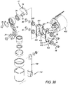
- FIG. 30 is an exploded perspective view of the motor mount, motor and other components from FIG. 29 ;
- FIG. 31 is a perspective view showing the motor and motor mount exploded out of the housing
- FIG. 32 is a perspective view showing the motor and motor mount exploded out of the housing on the opposite side as FIG. 31 ;
- FIG. 33 is a cross-sectional perspective view
- FIG. 34 is a perspective view of a percussive massage device that includes a heart rate monitor
- FIG. 35 is a perspective view of a percussive massage device that includes a heart rate monitor with first and second pulse contacts;
- FIG. 36 is a perspective view of a percussive massage device that includes a temperature sensor or monitor;
- FIG. 36A is a detailed view of the temperature reading on the screen taken from FIG. 34 ;
- FIG. 37 is a side elevational schematic of a percussive therapy device with a heated male attachment member
- FIG. 38 is a side elevational schematic of a percussive therapy device with a male attachment member with first and second electrical contacts;
- FIG. 39 is a bottom view of male attachment member with first and second electrical contacts
- FIG. 40 is a massage member with a heating element therein;
- FIG. 41 is a perspective view of a percussive therapy device that includes a gyroscope and accelerometer;
- FIGS. 42A-C are perspective views of a percussive therapy device and graphical representations thereof on a display;
- FIG. 43 is a perspective view of an attachment configured to be operably connected with a percussive therapy device
- FIG. 44 is a perspective view of an attachment configured to be operably connected with a percussive therapy device
- FIG. 45 is a bottom view of an attachment configured to be operably connected with a percussive therapy device
- FIG. 46 is a perspective view of a percussive therapy system including a percussive therapy device and an attachment thereon;
- FIG. 47 is a perspective view of a percussive therapy system including a percussive therapy device and an attachment thereon;
- FIG. 48 is a flow diagram of a method of providing at least one therapeutic effect to a user in accordance with an embodiment of the present invention
- references in this specification to “one embodiment” or “an embodiment” means that a particular feature, structure, or characteristic described in connection with the embodiment is included in at least one embodiment of the disclosure. Appearances of the phrase “in one embodiment” in various places in the specification do not necessarily refer to the same embodiment, nor are separate or alternative embodiments mutually exclusive of other embodiments. Moreover, various features are described which may be exhibited by some embodiments and not by others. Similarly, various requirements are described which may be requirements for some embodiments but not other embodiments.
- FIG. 1 shows an embodiment of a percussive massage device 400 that includes a rechargeable battery (and replaceable or removable battery) 114 ( FIG. 19 ).
- the percussive massage device 400 includes three handle portions (referred to herein as first handle portion 143 , second handle portion 145 and third handle portion 147 ) that cooperate to define a central or handle opening 149 . All of the handle portions are long enough that they are configured such that a person can grasp that particular handle portion to utilize the device. The ability to grasp the different handle portions allows a person (when using the device on their own body) to use the device on different body parts and from different angles, thus providing the ability to reach body parts, such as the back, that might not be possible without the three handle portions.
- the first handle portion 143 defines a first handle portion axis A 1
- the second handle portion 145 defines a second handle portion axis A 2
- the third handle portion 147 defines a third handle portion axis A 3 that cooperate to form a triangle.
- the battery 114 is housed in the second handle portion 145 and the motor 406 ( FIG. 19 ) is housed in the third handle portion 147 .
- the first handle portion 143 has an interior edge 143 a
- the second handle portion 145 has an interior edge 145 a
- the third handle portion 147 has an interior edge 147 a , which all cooperate to at least partially define the handle opening 149 .
- FIG. 1 the first handle portion 143 defines a first handle portion axis A 1
- the second handle portion 145 defines a second handle portion axis A 2
- the third handle portion 147 defines a third handle portion axis A 3 that cooperate to form a triangle.
- the battery 114 is housed in the second handle portion 145
- the first handle portion 143 includes a finger protrusion 151 that includes a finger surface 151 a or fourth interior surface that extends between the interior edge 143 a of the first handle portion and the interior edge 147 a of the third handle portion 147 and at least partially defines the handle opening 149 .
- a user can place their index finger against the finger surface 151 a .
- the finger protrusion and surface provide a feedback point or support surface such that when a user places their index finger against the surface it helps the user with control and comfort of using the device.
- at least a portion of the finger surface 151 a is straight, as shown in FIG. 1 (as opposed to the other “corners” of the handle opening 149 being rounded).
- the first handle portion interior surface, second handle portion interior surface, third handle portion interior surface and finger surface cooperate to define a quadrilateral with radii or rounded edges between each of the straight surfaces.
- FIGS. 2-20 show embodiments in accordance with a percussion massage device with a force meter.
- FIG. 2 is a block diagram showing interconnected components of a percussive therapy device with a force meter 400 .
- the percussive therapy device with force meter 400 includes a microcontroller unit 701 , a battery pack management unit 702 , an NTC sensor 703 , a power charging management unit 704 , a wireless charging management unit 705 , a wireless charging receiving system 706 , a voltage management unit 707 (5V 3.3V Voltage Management in drawings), battery charging inputs 708 (20V 2.25 A Charging Inputs in drawings), a display 709 (Force/Battery/Speed Display in drawings), a wireless control unit 710 (Bluetooth Control in drawings), an OLED screen 711 , an OLED screen control system 712 , a motor 713 , a motor drive system 714 , a PWM speed setup unit 715 , an over-current protection unit 7
- the microcontroller unit 701 in an embodiment, is a microcontroller unit including a processor, a memory, and input/output peripherals. In other embodiments, however the microcontroller unit 701 is an ST Microelectronics STM32F030K6 series of microcontroller units, STM32F030C8T6 series of microcontrollers, STM32F030CCT6 series of microcontrollers, or an equivalent microcontroller.
- the memory of the microcontroller unit 701 is configured to store machine-readable code for processing by the processor of the microcontroller unit 701 .
- Various other configurations may exist depending on whether the designer of the percussive massage device with force meter 400 desires to implement the machine-readable code in software, firmware, or both.
- the machine-readable code is stored on the memory and configured to be executed by a processor of the microcontroller 701 .
- the machine-readable code is stored on computer-readable media.
- the battery pack management unit 702 in an embodiment, is implemented in firmware or software and configured to be used in connection with the microcontroller unit 701 .
- the firmware or software is stored in memory (not shown) and configured to be obtainable by the microcontroller unit 701 .
- the battery pack management unit 702 may also be a combination of firmware, software, and hardware, in another embodiment.
- the battery pack management unit 702 is coupled with the NTC sensor 703 .
- the NTC sensor 703 is a negative temperature coefficient thermistor used by the battery pack management unit 702 to sense temperature of the battery pack.
- the NTC sensor 703 is a thermistor with B value of 3950+/ ⁇ 1%, and a resistance of 10 kn.
- the thermistor has a resistance of 100 kn.
- a thermistor is a resistor whose resistance is dependent upon temperature.
- the NTC sensor 703 may be another type of temperature sensing device or component used in connection with the battery pack management unit 702 .
- the wireless charging management unit 705 in an embodiment, is coupled to the battery pack management unit 702 and the battery charging inputs 708 .
- the battery or battery pack is charged using other conventional methodologies, such as, for example, charging the battery or battery pack using a wire or cord coupled to the battery charging inputs 708 .
- the wireless charging receiving system 706 in an embodiment, is coupled to the power charging management unit 704 and the display 709 .
- the wireless charging receiving system 706 includes one or more of firmware, software, and hardware.
- the wireless charging receiving system 706 is configured to receive information pertaining to battery capacity, charging metrics, and other information pertaining to wireless charging, and to pass along the information to the power charging management unit 704 .
- the wireless charging receiving system 706 preferably includes a wireless charging pad used to charge the percussive massage device with force meter 400 .
- One of ordinary skill in the art would understand that a variety of wireless charging devices may be utilized to wirelessly charge the percussive massage device with force meter 400 .
- the Qi wireless charging standard and related devices may be utilized to wirelessly charge the percussive massage device with force meter 400 .
- the voltage management unit 707 in an embodiment, is a DC voltage regulator that steps down 5 volt to 3.3 volt power for use by the microcontroller unit 701 .
- the voltage management unit 707 may also perform additional functions for management of 3.3 volt power for use by the microcontroller unit 701 .
- the voltage management unit 707 is implemented using a series of electronic components such as, for example, implementing a resistive divider using electronic components.
- the voltage management unit 707 is a stand-alone voltage regulator module and/or device designed to step down voltage from 5 volts to 3.3 volts.
- One of ordinary skill in the art would understand the various methodologies and devices available to step down 5 volts to 3.3 volts.
- the battery charging inputs 708 are interfaces by which a wire or cord may be inserted for charging the percussive massage device with force meter 400 .
- a standardized barrel connector is the battery charging inputs 708 .
- the battery charging inputs 708 is a USB connector.
- Other more specialized charging methodologies may require a particular battery charging input not described above.
- the display 709 displays a series of LEDs depicting an amount of force applied by the percussive massage device with force meter 400 .
- the display 709 displays a series of LEDs depicting the current battery or battery pack charge of the percussive massage device with force meter 400 .
- the display 709 displays a series of LEDs depicting the current speed of the percussive massage device with force meter 400 .
- LEDs have been specified in the above-referenced embodiments, other embodiments not using LEDs are within the scope of this disclosure, such as, for example, liquid crystal displays, OLEDs, CRT displays, or plasma displays.
- the display 709 is a 128 ⁇ 64 pixel OLED display.
- the wireless control unit 710 is a wireless connectivity device that may be implemented in a wireless microcontroller unit.
- the wireless control unit 710 is a Bluetooth transceiver module configured to couple, via Bluetooth, to a remote device.
- the Bluetooth module is a Bluetooth Low-Energy (BLE) module configured to be run in broadcast mode.
- the wireless control unit 710 is coupled to the microcontroller unit 701 .
- the remote device is a smartphone having an embedded Bluetooth module.
- the remote device is a personal computer having Bluetooth connectivity.
- other wireless connectivity standards besides the Bluetooth wireless standard may be utilized. It will be appreciated that the Bluetooth connectivity or other wireless connectivity may be described herein as being implemented in a wireless connection device.
- the wireless connection device can be a separate module, can be included in the MCU or other component of the device, or can be a separate chip.
- the percussive therapy device including a wireless connection device means that the percussive massage device can connect to another electronic device wirelessly (e.g., a phone, tablet, computer, computer, voice controlled speaker, regular speaker, etc.).
- another electronic device wirelessly e.g., a phone, tablet, computer, computer, voice controlled speaker, regular speaker, etc.
- low-power wireless control modules may be advantageous when the percussive massage device with force meter 400 is utilizing a battery or battery pack.
- the OLED screen 711 and the OLED screen control system 712 are configured to display substantially the same information as the display 709 referenced above.
- the OLED screen 711 is coupled to the OLED screen control system 511 .
- the OLED screen control system 712 is coupled to the microcontroller unit 701 , the OLED screen 711 , and the power switch unit 717 .
- the display 709 and the OLED screen 711 may be redundant and it may only be necessary to utilize one or the other.
- the motor 713 in an embodiment, is a brushless direct current (BLDC) motor.
- the motor 713 and the motor drive system 714 are configured to vary the speed (i.e., rotational motion) that may be converted to reciprocal motion.
- the motor 713 is a brushed DC motor, a brushed AC motor, or a brushless AC motor.
- BLDC brushless direct current
- the motor 713 is a brushed DC motor, a brushed AC motor, or a brushless AC motor.
- a brushless or brushed motor, or direct current or alternating current may vary depending on the application and intended size, battery power, and use.
- the PWM speed setup unit 715 in an embodiment, is used to control pulse width modulation utilized to drive the motor 713 .
- the PWM speed setup unit 715 is coupled to the microcontroller unit 701 and the over-current protection unit 716 .
- pulse width modulation is one way to vary the average power applied to the motor 713 , resulting in varying speed as desired.
- the over-current protection unit 716 may be a feature of an integrated system-in-package to prevent damage caused by high currents to the motor.
- the over-current protection unit 716 is implemented using a series of electronic components configured to protect the motor from excessively high current.
- the power switch unit 717 in an embodiment, is configured to turn on and turn off the percussive massage device with force meter 400 .
- the power switch unit 717 is coupled to the OLED screen control system 712 and the microcontroller unit 701 .
- the power switch unit 717 is the switch 405 .
- FIG. 3 shows a circuit diagram of the microcontroller unit 701 with pin outputs.
- the STM32F030K6 series of microcontroller units is utilized.
- the circuit diagram depicts +3.3 volt power being provided to the VDD inputs of the microcontroller unit 701 .
- Input PA 3 is labeled “Motor_VOL”, the voltage of the motor 713 .
- Input PA 2 is “bt_v”, the battery or battery pack voltage.
- the microcontroller unit is configured to receive analog voltage on inputs PA 2 and PA 3 and to convert it to digital voltage using the microcontroller's analog-to-digital converter.
- the analog-to-digital converter is a 12-bit ADC.
- One of ordinary skill in the art would understand that other microcontrollers may utilize voltage sensing and analog-to-digital converters to perform similar functions.
- an analog-to-digital converter module separate from a microcontroller may be utilized.
- FIG. 4 shows a circuit diagram used for battery voltage detection.
- +BT the positive battery terminal 602
- the positive battery terminal 602 is coupled to a circuit consisting of a P-channel MOSFET 604 , an N-Channel MOSFET 608 , 0.1 ⁇ f capacitor 610 , 100 k ⁇ resistors 612 , 614 , 68 k ⁇ resistor 616 , 1 k ⁇ resistors 618 , 620 , and 10 k ⁇ resistors 622 , 624 .
- the circuit is configured to provide an input analog voltage of the battery or battery pack, or bt_v, to the microcontroller unit 701 of FIG. 2 .
- voltage of the battery or battery pack may be achieved using a voltage reader coupled to the terminals of the battery or battery pack.
- FIG. 5 shows a circuit diagram for detection and measurement of voltage of the motor 713 of the percussive massage device.
- voltage sensing resistor 626 is coupled in parallel with the microcontroller unit 701 , and coupled to the motor 713 .
- the voltage sensing resistor has a value of 0.0025 ⁇ .
- the circuit depicted in FIG. 5 is configured to provide the Motor_VOL input into the microcontroller unit 701 of FIG. 2 .
- the input analog voltage is amplified.
- the voltage of the motor 713 is measured or sensed using a separate series of electronic components or a standalone device and input into a microprocessor for use with the method of displaying a force on the percussive massage device.
- FIG. 6 is a flow diagram showing a method 800 of detecting force applied by the percussive massage device in accordance with a preferred embodiment.
- a voltage magnitude V is obtained.
- voltage magnitude V is an analog voltage obtained by using the circuit disclosed in FIG. 2 .
- a block curve signal from the motor 713 i.e., a Hall effect sensor
- voltage that corresponds to the current operating speed of the motor 713 may be generated in a variety of other ways.
- the voltage magnitude V may be input to a microcontroller unit 701 that converts analog voltage to digital voltage using an analog-to-digital converter, such as that implemented in the STM32F030K6 microcontroller unit.
- the STM32F030K6 microcontroller unit coverts analog voltage magnitude to a digital code corresponding to the 12-bit ADC (i.e., 0 to 4096).
- the digital code represents a voltage magnitude corresponding to the original voltage magnitude V obtained.
- a lookup table is generated that correlates voltage V to force magnitude F.
- the lookup table is generated using a method 900 of generating a lookup table correlating voltage to force.
- the force magnitude F may be expressed in pounds of force. In an alternative embodiment, the force magnitude F may be expressed in Newtons of force.
- the force magnitude F corresponding to voltage magnitude V is displayed on the percussive massage device with force meter 400 .
- a series of LED lights may be utilized to depict varying amounts of force as the force is being applied by the percussive massage device with force meter 400 .
- the series of LED lights consists of 12 LED lights.
- FIG. 7 is a flow diagram showing a method 900 of generating a lookup table correlating voltage to force.
- a maximum magnitude of force F MAX .
- the magnitude of Fix may be determined by assessing the maximum desired force to apply using the percussive massage device with force meter 400 .
- F MAX is 60 pounds of force.
- a maximum magnitude of voltage, V MAX is determined.
- the magnitude of V MAX may be determined by assessing the maximum theoretical voltage change possible by the percussive massage device with force meter 400 .
- V MAX is 1.8 volts.
- Step 906 F MAX is divided into equal increments. Using the above example from Step 902 , 60 pounds of force is divided into 60 one-pound increments.
- V MAX is divided into the same amount of increments as determined in Step 906 above.
- 1.8 volts is divided into 60 0.03-volt increments.
- a lookup table (LUT) is generated that correlates the increments of pounds of force with the increments of voltage. This necessarily creates a linear relationship between force and voltage.
- FIG. 8 is a graph plotting the LUT for use by the method of detecting force of FIG. 6 that was generated using the specific example identified in FIG. 7 . The graph depicts calculated force that was calculated using the method 900 .
- a problem may arise in that the theoretical maximum voltage assumption at Step 904 in the method 900 is inaccurate. It may also be the case that as the percussive massage device with force meter 400 is used, the maximum available voltage degrades over time. In other words, the battery or battery pack voltage may decrease.
- FIG. 9 is a flow diagram showing a method 1000 of calibrating a LUT.
- battery pack voltage BV is obtained.
- battery pack voltage magnitude BV is an analog voltage obtained by using the circuit disclosed in FIG. 4 .
- the battery pack voltage magnitude BV may be input to a microcontroller unit 701 that converts analog voltage to digital voltage using an analog-to-digital converter, such as that implemented in the STM32F030K6 microcontroller unit.
- the STM32F030K6 microcontroller unit coverts analog voltage magnitude to a digital code corresponding to the 12-bit ADC (i.e., 0 to 4096).
- the digital code represents a voltage magnitude corresponding to the original battery pack voltage magnitude BV obtained.
- V MAX is set to the actual battery voltage magnitude BV output. As an example, may decrease from 1.8 volts to 1.74 volts, a 0.6 volt decrease.
- the LUT linear correlation is adjusted to reflect the lower V MAX .
- FIG. 10 is a graph plotting the LUT calculated by the method 900 against the LUT calibrated by using the method 1000 . The LUT resulting from method 1000 depicts a calibrated force rather than a calculated force.
- FIG. 11 is a flow diagram showing a method 1100 of calibrating a LUT.
- the method 1100 may be performed after the method 900 , or entirely separately from the method 900 .
- battery pack voltage BV is measured. In an embodiment, the measurement is done without applying any force from the percussive massage device with force meter 400 . In an embodiment, the battery pack voltage BV is measured using an external voltage meter. In another embodiment, the battery pack and/or microcontroller unit 701 have embedded solutions for directly measuring battery pack voltage BV.
- Step 1104 the display on the percussive massage device with force meter 400 that displays the force magnitude F is read to determine the force magnitude F corresponding to the measured battery pack voltage BV.
- a force meter is used to measure actual force being applied.
- the force meter is a push/pull force meter.
- the direct measurement of force allows calibration of the LUT by comparing the displayed force magnitude F with the measured actual force.
- the LUT is updated with a corrected force corresponding with the measured battery pack voltage BV.
- Steps 1102 - 1106 are repeated for each successive voltage increment. In the embodiment depicted in accordance with the method 900 , Steps 1102 - 1106 are repeated for every 0.03-volt increment.
- FIG. 12 is a graph plotting the LUT calculated by the method 1100 after all 3-volt increments had been updated.
- FIG. 13 is a flow diagram showing a method 1200 of detecting force applied by a percussive massage device in accordance with a preferred embodiment.
- current magnitude C of a battery pack is obtained.
- current magnitude C is input into the microcontroller unit 701 .
- voltage magnitude BV of a battery pack is obtained.
- voltage magnitude BV is input into the microcontroller unit 701 .
- power is calculated using the product of C and BV.
- the microcontroller unit 701 is configured to calculate power by multiplying C and BV.
- a lookup table is generated that correlates power magnitude P to force magnitude F.
- the lookup table is generated using a method 1300 of generating a lookup table correlating power to force.
- the power magnitude P may be expressed in watts.
- force magnitude F may be expressed in pounds of force or Newtons of force.
- the force magnitude F corresponding to power magnitude P is displayed on the percussive massage device with force meter 400 .
- a series of LED lights may be utilized to depict varying amounts of force as the force is being applied by the percussive massage device with force meter 400 .
- the series of LED lights consists of 12 LED lights.
- FIG. 14 is a flow diagram showing a method 1300 of generating a lookup table correlating power to force.
- a maximum magnitude of power, F MAX is determined.
- Total EP MAX P MAX ⁇ Total EP Equation 1:
- Equation 2 may be utilized to calculate Total EP, which is then input into Equation 1 above.
- Total EP EP BATTERY ⁇ EP PCBA ⁇ EP MOTOR Equation 2: where Total EP, EP BATTERY , EP PCBA , and EP MOTOR are all expressed in percentages, and where PCBA is a printed circuit board assembly.
- EP Battery
- PCBA PCBA
- EP Motor
- P MAX is calculated by multiplying the maximum voltage V MAX and the maximum amperage C MAX of the battery pack such as in Equation 3. P MAX is then input into Equation 1.
- V MAX is 16.8 volts and C MAX is 20 amperes.
- P MAX is 336 watts.
- a minimum amount of power P MIN is determined. It will be recognized by one of ordinary skill in the art that the power without any force being applied (i.e., no load) will be non-zero. Thus, P MIN of 12 watts is assumed. One of ordinary skill will also understand that the value of is equivalent to the rated power without load, which may be derived from V MAX and C MIN .
- a maximum magnitude of force is determined.
- the magnitude of F MAX may be determined by assessing the maximum desired force to apply using the percussive massage device with force meter 400 .
- F MAX is 60 pounds of force.
- Total EP MAX is divided into equal increments.
- Total EP MAX is divided in 3 watt increments per one pound of force, starting at P MIN (12 watts). It will be recognized by one of ordinary skill in the art that if F MAX is 60 pounds of force, the total desired force output of the percussive massage device with force meter 400 , then 60 pounds of force correlates to 189 watts, within the calculated Total EP MAX .
- a LUT is generated that correlates the increments of pounds of force with the increments of power in watts. This necessarily creates a linear relationship between force and voltage.
- FIG. 15 is a graph plotting the LUT for use by the method of detecting force of FIG. 13 that was generated using the specific example identified in FIG. 10 . The graph depicts calculated force that was calculated using the method 1200 .
- a problem may arise in that the measured voltage of the battery pack at Step 1204 in the method 1200 is inaccurate. It may also be the case that as the percussive massage device with force meter 400 is used, the maximum available voltage degrades over time. In other words, the battery or battery pack voltage may decrease.
- FIG. 16 is a flow diagram showing a method 1400 of calibrating a LUT.
- the method 1400 may be performed after the method 900 or the method 1200 , or entirely separately from the method 900 or the method 1200 .
- current magnitude C of a battery pack is obtained.
- current magnitude C is input into the microcontroller unit 701 .
- battery pack voltage BV is measured. In an embodiment, the measurement is done without applying any force from the percussive massage device with force meter 400 . In an embodiment, the battery pack voltage BV is measured using an external voltage meter. In another embodiment, the battery pack and/or microcontroller unit 701 have embedded solutions for directly measuring battery pack voltage BV.
- power is calculated using the product of C and BV. In an embodiment, the microcontroller unit 701 is configured to calculate power by multiplying C and BV.
- Step 1408 the display on the percussive massage device with force meter 400 that displays the force magnitude F is read to determine the force magnitude F corresponding to the calculated power.
- a force meter is used to measure actual force being applied.
- the force meter is a push/pull force meter.
- the direct measurement of force allows calibration of the LUT by comparing the displayed force magnitude F with the measured actual force.
- the LUT is updated with a corrected force corresponding with the measured power.
- Steps 1402 - 1410 are repeated for each power or force increment. In the embodiment depicted in accordance with the method 900 , Steps 1402 - 1410 are repeated for every 3-watt increment.
- FIG. 17 is a graph plotting the LUT calculated by the method 1400 after all 3-watt increments had been updated.
- FIGS. 18-19 show an exemplary percussive massage device 400 that embodies the features disclosed herein.
- the percussive massage device 400 includes a housing 101 , an electrical source or battery pack 114 , a motor 406 positioned in the housing 101 , and a switch 405 for activating the motor 406 .
- the electronics includes the controller that is configured to obtain a voltage of the motor, generate a lookup table correlating voltage to force applied by the percussive massage device, and display a force magnitude corresponding to the obtained voltage using the lookup table.
- FIG. 20 is a perspective view of the motor 406 .
- the motor 406 is located in the head portion 12 .
- the percussive massage device 400 can include a rotatable arm that is part of rotation housing 44 .
- the motor 406 is located in the rotation housing 44 , which is housed with the head portion 12 of the housing 101 .
- the rotation capability can be omitted.
- the device includes a push rod or shaft 14 that is connected directly to a shaft 16 that is rotated by the motor 406 and the motor shaft 21 extending therefrom.
- the shaft 16 can be part of a counterweight assembly 17 that includes a counterweight 19 .
- the push rod 14 is L-shaped or includes an arc shape, as shown in FIGS. 22A-22B .
- the point where the push rod 14 is connected to the shaft 16 is offset from the reciprocating path that the distal end 18 of the push rod 14 (and the massage attachment 628 ) travel. This capability is provided by the arc or L-shape.
- the push rod 14 is designed such that it can transmit the force at least partially diagonally or in an arc along its shape instead of vertically so the motor can be located at or near the middle of the device, otherwise a large protrusion would be necessary to keep the shaft in the center with the motor offset therefrom (and positioned in the protrusion).
- the arc also allows the push rod 14 to have a close clearance with the motor, as shown in FIGS. 22A and 22B and allows the outer housing to be smaller than similar prior art devices, therefore making the device 400 lower profile.
- FIG. 22A shows the push rod 14 at the bottom dead center of its travel
- FIG. 22B shows the push rod 14 at the top dead center of its travel.
- one or more bearings 20 are included at the proximal end of the push rod 14 where it connects to the motor to counteract the diagonal forces and preventing the push rod 14 from moving and touching the motor 406 .
- the bearing 20 is received on shaft 16 and a threaded fastener 26 is received in a co-axial opening 16 a in shaft 16 .
- the proximal end of the push rod 14 is received on bearing 20 .
- device 400 includes a number of dampening components that are made of an elastomer or the like and damp vibrations to keep the device relatively quiet.
- device 400 includes dampening rings 426 (similar to inner suspension rings 219 ) that surround the rotation housing 44 (with first and second rotation housing halves 44 a and 44 b ) and help dampen the sound of vibration between the rotation housing and outer housing 101 .
- the device 400 preferably also includes a motor mount 24 that secures the motor 406 in place and is secured to the housing 101 .
- Motor 406 includes a receiving member 28 with three protrusions 30 (and number between one and ten can be included) that is received in a protrusion opening 32 defined in the motor mount 24 (in first wall 38 ). Flanges 34 extending from the motor mount 24 help keep the protrusions 30 in place.
- the motor 406 is preferably secured via threaded fasteners or the like to the motor mount 24 .
- Motor shaft 21 extends into the motor mount interior 36 , which is defined between first and second walls 38 and a side 40 that extends part of the way around the circumference.
- the counterweight assembly 17 , proximal end of the push rod 14 and related components for converting the rotation of the motor shaft 21 to reciprocating motion are position in the motor mount interior 36 .
- the push rod 14 extends downwardly out of the motor mount interior and through a push rod opening 42 in the side 40 .
- the motor mount 24 is connected directly to the housing 101 via fasteners 46 that are secured to mounting members 48 in the housing (see FIG. 23A ).
- the term push rod assembly used herein includes any of the components discussed herein or combinations thereof, e.g., push rod 14 , output shaft 108 , second rod portion 236 , that extend from the rotating motor shaft 21 or the like that provide reciprocating motion and include the attachment on the distal end thereof.
- the push rod assembly also includes the male connector 110 (and any related components) or any other connector at the end of the reciprocating components that allows connection of an attachment to be used for massage or therapy.
- the device 400 is associated with and can be operated by an app or software that runs on a mobile device such as a phone, watch or tablet (or any computer).
- the app can connect to the device 400 via bluetooth or other wireless connection protocol.
- the app can have any or all of the following functions.
- any of the functions discussed herein can be added to the touch screen/scroll wheel or button(s) capability directly on the device. If the user walks or is located too far away from the device, the device will not work or activate.
- the device can be turned on an off using the app as well as the touch screen or button on the device.
- the app can control the variable speeds (e.g., anywhere between 1750-3000 RPM).
- a timer can be implemented so the device stops after a predetermined period of time.
- the device via the app or the touch screen and other functional buttons, etc. includes different treatment protocols or routines associated therewith.
- the device can vary different aspects or outputs of the device or make changes based on time, speed (frequency), amplitude (stroke), arm position, force, temperature, grip (i.e., which handle portion to grip), attachment (e.g., cone, ball, dampener, etc.) and body part.
- the device via the app, touch screen, haptic feedback or audibly via a speaker
- One of ordinary skill in the art will understand that, depending upon the particular design of the device, one or more of these outputs are applicable, while in other devices, all options described are applicable.
- the device runs through a preprogrammed routine. For example, the device may operate at a first RPM for a first period of time and then operate at a second RPM for a second period of time and/or at a first amplitude for a first period of time and then operate at a second amplitude for a second period of time.
- the routines can also include prompts (e.g., haptic feedback) for letting the user to know to move to a new body part.
- prompts e.g., haptic feedback
- routines or treatments can be related to recovery, blood flow increase, performance, etc. and can each include a preprogrammed routine or protocol.
- routines can also help facilitate certain activities, such as sleep, interval training, stairs, post-run, post-workout, recovery, wellness, post-core exercise, high intensity (plyometric) workouts, among others.
- the routines can also assist in providing relief and recovery from ailments such as plantar fasciitis, “tech neck,” muscle cramps, jet lag, sciatica, carpal tunnel, knots, and shin splints, among others.
- the routines can also prompt or instruct the user to switch attachments (e.g., attachment 628 shown in FIG. 21 ) or positions of the arm or rotation housing.
- the prompts can include sounds, haptic feedback (e.g., vibration of the device or mobile device), textual instructions or visual representation such as a graphic or picture on the app or touch screen, etc.
- the app may instruct the user to start with the ball attachment with the arm in position two. Then the user hits start and the device runs at a first frequency for a predetermined amount of time.
- the app or device then prompts the user to begin the next step in the routine and instructs the user to change to the cone attachment and to place the arm in position 1 (e.g., see the arm position in FIG. 18 ).
- the arm can include any number of positions, e.g., 1 - 10 positions or 1 - 3 positions or 1 - 2 positions.
- the user hits start again and the device runs at a second frequency for a predetermined amount of time.
- the protocol can be divided into steps where, at each step, varied outputs are predetermined or specified.
- the device 400 includes a housing 101 , an electrical source 114 , a motor 406 positioned in the housing 101 , a switch 405 (which can be any of the touch screen 409 , rocker button 447 , button 403 or any other switch or button) for activating the motor 406 , and a routine controller 630 .
- the device 400 is configured to mate with an attachment 628 .
- the attachment can be, for example, the attachment 628 shown in FIG. 21 .
- the attachment is affixed to the male connector 110 so that the shaft or push rod assembly 108 moves the attachment reciprocally in accordance with a specified amplitude.
- the amplitude is depicted in FIGS. 22A and 22B , where FIG. 22A shows the attachment at a maximum extended position and FIG. 22B shows the attachment at a minimum extended position.
- the distance between maximum and minimum extended positions can, in an embodiment, define the amplitude.
- the routine controller 630 is configured to perform a routine in connection with one or more specified protocols.
- the routine controller 630 can be, for example, the microcontroller unit 701 depicted in FIG. 2 .
- the routine controller 630 can also be a standalone microcontroller separate from the microcontroller 701 .
- the routine controller can step through different steps of a specified protocol designed to target specified muscle groups and to provide certain therapeutic effects, as described herein.
- FIG. 24 is a table showing an example of a protocol in accordance with a preferred embodiment.
- Protocol 1 is divided into four steps, each depicting a specified time, speed, amplitude, attachment, force, temperature, and grip.
- the device 400 is activated for 30 seconds at a speed of 1550 RPM.
- a routine controller 630 may be utilized to turn on the percussive massage device and implement a speed of the attachment 628 of 1550 RPM.
- the amplitude of the percussive massage device is set to be 2 in accordance with Protocol 1 . This may translate to a specified distance that an attachment 628 moves while in use, as described above.
- Step 1 also specifies a dampener attachment affixed to the device 400 , a force of “1” be applied by the device 400 , and a temperature of 21° C. be applied to the attachment.
- the force to be applied by the device 400 may depend upon the pressure exerted by the user in pressing the attachment onto a person's body part. As described more fully herein, the force to be applied by the device 400 may be the target force. In an embodiment where the user provides pressure to exert a particular force upon a person's body part, the routine controller 630 may adjust the output of the device 400 to ensure that the force actually applied by the attachment is the target force. The routine controller 630 may also be configured to provide feedback to the user to increase or decrease pressure on a person's body part to meet the target force. Each of these embodiments is applicable to each of the steps of a given protocol, including in Steps 2 - 4 below, as well as Steps 1 - 4 of the protocol shown in FIG. 25 .
- Step 1 also specifies that the device 400 is to be operated using grip 1 .
- Grip 1 may be a grip on the first handle portion 143 , otherwise referred to as a “regular” or “standard” grip.
- Grip 2 for example, may be a grip on the third handle portion 147 , otherwise referred to as a “reverse” grip.
- An “inverse” grip can also be used on third handle portion 147 .
- Grip 3 for example, may be a grip shown on the second handle portion 145 , otherwise referred to as a “base” grip.
- Protocol 1 specifies that the device 400 be activated for 15 seconds at 2100 RPM, with an amplitude of “3”, a force of “3”, and a temperature of 26° C.
- Step 2 specifies that the small ball attachment 628 be used, and that the device 400 is to be operated using grip 1 . Step 2 therefore requires that the dampener attachment in Step 1 be replaced by the small ball attachment, but specifies that the same grip is to be used.
- Protocol 1 specifies that the device 400 be activated for 30 seconds, at 2200 RPM, with an amplitude of “1”, a force of “3”, and a temperature of 29° C.
- Step 3 specifies that the dampener attachment 628 be used, and that the device 400 is to be operated using grip 1 . Step 3 therefore requires that the small ball attachment in Step 2 be replaced by the dampener attachment, but specifies that the same grip is to be used.
- Protocol 1 specifies that the device 400 be activated for 45 seconds, at 2400 RPM, with an amplitude of “4”, a force of “2”, and a temperature of 32° C.
- Step 3 specifies that the large ball attachment be used, and that the device 400 is to be operated using grip 1 . Step 3 therefore requires that the dampener attachment in Step 2 be replaced by the large ball attachment, but specifies that the same grip is to be used.
- Protocol 1 is provided as an example to the reader of many of the different outputs that can be changed during a myriad of treatment protocols that can be provided or developed. It will be further appreciated that any one or more of the outputs can be a part of a protocol or routine and any of the outputs discussed herein can be omitted.
- a protocol may only include time and speed or only time speed and force, or only time, speed and grip or any other combination of the outputs described herein.
- FIG. 25 is a table showing an example of a “Shin Splints” protocol in accordance with a preferred embodiment.
- the Shin Splints protocol is divided into four steps, each depicting a specified time, speed, amplitude, attachment, force, temperature, and grip, but also specifying a particular arm position and body part to which to apply the attachment.
- the device 400 is activated for 1 minute at a speed of 1500 RPM, with an amplitude of “1”, a force of “2”, and a temperature of 21° C.
- Step 1 specifies that the dampener attachment be used, and that the device 400 is to be operated using grip 2 (“Reverse”), to the right shin.
- Step 1 also specifies the arm position to be used is arm position 1 .
- arm position 1 One of ordinary skill in the art would understand that the numbers of arm position (e.g., 1 , 2 , 3 , 4 , etc.) are predetermined arm positions intended to be used during a particular protocol. The part of the body to which the attachment 628 is to be applied is one of the factors in determining an optimal arm position. The arm position, however, may be determined by the user and is not required to otherwise implement a protocol. As discussed above, a “standard” grip may be utilized with arm position to apply to specific parts of the body, a “reverse” grip may be utilized with arm position to apply to specific parts of the body, and a “base” grip may be utilized with arm position to apply to specific parts of the body.
- any arm position in combination with the particular grip 143 , 145 , 147 may vary depending on the application.
- setting the arm position of a device 400 depends upon the specific device. For example, certain devices may allow a user to adjust arm position while others do not. For those that do not, this step does not apply. In other embodiments, this step may be performed during execution of the steps of the particular protocol.
- the Shin Splints protocol specifies that the device 400 be activated for 1 minute at 1500 RPM, with an amplitude of “1”, a force of “2”, and a temperature of 21° C.
- Step 2 specifies that the dampener attachment be used, and that the device 400 is to be operated using grip 2 (“Reverse”), at an arm position 1 , to the left shin. Step 2 therefore uses the same attachment, grip, and arm position as Step 1 , but is applied to the other shin.
- the Shin Splints protocol specifies that the device 400 be activated for 1 minute at 2000 RPM, with an amplitude of “3”, a force of “3”, and a temperature of 24° C.
- Step 2 specifies that the dampener attachment be used, and that the device 400 is to be operated using grip 3 (“Base”), at an arm position 1 , to the right calf.
- Step 3 therefore requires that the user change grips from “reverse” to “base” grips, but specifies that the same attachment and arm position be used.
- the Shin Splints protocol specifies that the device 400 be activated for 1 minute at 2000 RPM, with an amplitude of “3”, a force of “3”, and a temperature of 24° C.
- Step 2 specifies that the dampener attachment be used, and that the device 400 is to be operated using grip 3 (“Base”), at an arm position 1 , to the left calf. Step 2 therefore uses the same attachment, grip, and arm position as Step 1 , but is applied to the other calf.
- FIG. 26A is a flow diagram showing an exemplary protocol initiation.
- Protocol 1 is initiated.
- Protocol 1 is the Protocol 1 depicted in FIG. 24 or the “Shin Splints” Protocol depicted in FIG. 25 .
- One of ordinary skill in the art would understand that Protocol 1 depicted in FIG. 24 does not include all of the outputs that are specified in the Shin Splints Protocol depicted in FIG. 25 , and thus, not all steps of the method 1500 apply to the Protocol 1 depicted in FIG. 24 .
- a user is prompted to set the arm position to the specified arm position.
- the user may be the person using the device 400 on their own body or on the body of another person.
- the arm position specified in the Shin Splints Protocol is arm position 1 , for example.
- the user is prompted to use a specified grip or handle portion 143 , 145 , 147 on the device 400 .
- the grip specified in the Shin Splints Protocol is the third handle portion 147 , for example. As described herein, the grip may vary depending on the particular protocol or step.
- Step 1510 the method determines whether the arm position and the grip position 143 , 145 , 147 are configured appropriately and whether the attachment 628 is affixed.
- Step 1510 may involve a prompt to the user by haptic feedback, application interface, or touch screen (among other types of prompts) in which the user is asked to proceed when the appropriate arm position, grip, and attachment are ready.
- the device 400 may sense that the arm position and grip are appropriate and that an attachment is affixed before proceeding automatically.
- Step 1510 is repeated until the arm position, grip, and attachment are ready.
- FIG. 26B is a flow diagram showing an exemplary Step 1 of the protocol, continuing the method 1500 where FIG. 26A left off.
- the method 1500 applies a specified time period (T 1 ) in which the device 400 is activated, a speed of the attachment, an amplitude of the attachment, a force of the attachment, and a temperature of the attachment.
- T 1 a specified time period
- the routine controller 630 may be applied by the routine controller 630 .
- the time period, speed, amplitude, and temperature are not necessarily dependent upon a user applying pressure to a body part.
- the user may be prompted to change the attachment 628 , arm position, and/or grip position 143 , 145 , 147 .
- These outputs may need to be implemented prior to the start of Step 2 of a protocol.
- the attachment 628 , arm position and grip position 143 , 145 , 147 remain the same.
- the user is prompted to set the arm position to the specified arm position.
- the user may be the person using the device 400 on their own body or on the body of another person.
- the user is prompted to use a specified grip 143 , 145 , 147 on the device 400 .
- the grip may vary depending on the particular protocol or step.
- the user is prompted to affix a specified attachment 628 to the device 400 .
- the attachment 628 may vary depending on the particular protocol or step.
- Step 1522 the method determines whether the arm position and the grip position 143 , 145 , 147 are configured appropriately and whether the attachment 628 is affixed. This step and all other like steps are optional.
- Step 1510 may involve a prompt to the user by haptic feedback, application interface, or touch screen (among other types of prompts) in which the user is prompted to move to the next step in the routine and/or requested to proceed when the appropriate arm position, grip, and attachment are ready.
- the device 400 may sense that the arm position and grip are appropriate and that an attachment is affixed before proceeding automatically.
- Step 1522 is repeated until the arm position, grip, and attachment are ready.
- FIG. 26C is a flow diagram showing an exemplary Step 2 of the protocol, continuing the method 1500 where FIG. 26B left off.
- Step 2 of the protocol is initiated.
- Step 2 for example, is Step 2 depicted in FIGS. 44 and 45 , for example.
- the force applied by the attachment 628 may require a user to exert pressure on a body part for a target force to be reached.
- the temperature may vary depending on whether the attachment 628 is applied to a body part, or not, and to which body part it is applied. Thus, the temperature may need to be adjusted during application of the attachment 628 to reach a desired temperature predetermined by the protocol. In another embodiment, the temperature may be adjusted by a user.
- Steps 1528 - 1534 steps substantially the same as Steps 1516 - 1522 are performed.
- Steps 3 - 4 are initiated in substantially the same manner as Steps 1 - 2 .
- Steps 3 and 4 may be Steps 3 and 4 of the Protocol 1 depicted in FIG. 24 or the Shin Splints Protocol depicted in FIG. 25 .
- Step 1534 can be omitted in a device where none of the grip, arm position or attachment can be sensed by the device. In this embodiment, the given protocol simply moves from step 1 to step 2 prompting the user to make a change (but regardless of whether the user has actually made a change).
- Step 1540 the force being applied by the attachment 628 is monitored.
- the method 1500 utilizes the force meter 400 to monitor the force actually being applied by the user.
- the force is displayed to the user.
- the force is displayed on an application interface 1584 such as a graphical user interface.
- an application interface 1584 such as a graphical user interface.
- individual use or combined use of the application interface 1584 , touch screen 1582 , the OLED screen 711 , or the like, may be used to display the force.
- FIG. 28 is a diagram showing a touch screen 1582 in accordance with an exemplary embodiment of the display of the force.
- a force display 1590 shows an exemplary embodiment of Step 1546 .
- the force display 1590 shows a series of force measurements over the course of the “Right Bicep” step of a protocol.
- a force display prompt 1592 is used to display a message to the user such as “PERFECT PRESSURE: WELL DONE” when the force applied by the attachment 628 matches or corresponds to a target force predetermined by the protocol.
- the force display prompt 1592 may recite “INCREASE PRESSURE” or the like if the measured force applied by the attachment 628 is lower than the target force predetermined by the protocol. Consequently, if the measured force applied by the attachment 628 is higher than the target force predetermined by the protocol, then the force display prompt 1592 may recite “DECREASE PRESSURE” or the like. The user may then adjust the pressure the user is exerting on the body part to either increase pressure or decrease pressure according to the force display prompt 1592 so that the measured force is equivalent or substantially equivalent to the target force.
- the user may be prompted to change the attachment 628 , arm position and/or grip position 143 , 145 , 147 .
- These outputs may need to be implemented prior to the start of Step 3 of a protocol.
- the attachment 628 and arm position remain the same, but the grip 143 , 145 , 147 is adjusted to the base grip.
- the user is prompted to set the arm position to the specified arm position.
- the user may be the person using the device 400 on their own body or on the body of another person.
- Steps 1548 - 1552 steps substantially the same as Steps 1516 - 1522 are performed.
- Steps 3 - 4 are initiated in substantially the same manner as Steps 1 - 2 .
- Steps 3 and 4 may be Steps 3 and 4 of the Protocol 1 depicted in FIG. 24 or the Shin Splints Protocol depicted in FIG. 25 .
- FIG. 27 is a diagram in accordance with an exemplary embodiment of an application interface 1584 .
- a protocol field 1556 is displayed to the user.
- the protocol field 1556 is “TECH NECK.”
- the protocol title 1556 also shows the overall time period of the protocol.
- the next portion of the interface 1584 shows step fields 1558 - 1568 of the protocol that are displayed to the user.
- the step fields identify the title of the step and time period of the step.
- step field 1558 is titled “RIGHT BICEP” (where the treatment will be provided) and the time period of activation is “0:30 MIN.”
- the interface 1584 also includes a current step field 1570 that identifies the current step title 1570 , a grip title display 1572 , and an attachment title display 1574 .
- the interface 1584 also includes a time display 1576 and a time remaining display 1578 to show the user how much time has occurred during that step and the time remaining in that step. Finally, the interface 1584 includes a control field 1580 to play, skip back, and skip forward from step to step.
- FIG. 28 shows a touch screen 1582 on a mobile device.
- the touch screen 1582 displays a graphic depicting a starting point 1586 “A” and an end point 1588 “B” (thereby defining a treatment path) showing the user where to apply the attachment 628 to the specified body part.
- the display instructs the user to move the attachment from the lower portion of the right bicep to the upper portion of the right bicep (the treatment path) during the current step.
- the user may be prompted or shown on the graphical user interface more than one treatment path (or a first treatment path and a second treatment path) on the same body part/muscle or on different body parts/muscles.
- the user may be prompted to first move the device along the path shown in FIG. 28 , but, during the same thirty second step may also be prompted or shown a path that is parallel to the path shown in FIG. 28 .
- FIGS. 29-33 show a device 457 similar to device 400 described above.
- the motor 402 is oriented differently (the motor shaft axis A 4 extends perpendicular to the motor shaft axis in device 400 ), as shown in FIG. 29 .
- the motor mount 401 includes a mounting wall 427 with first and second mounting flanges 429 extending therefrom and a shaft opening 430 defined therein.
- the threaded fasteners 46 extend through the central openings of the cylindrical dampening members 461 (and the openings in the mounting members 48 ) and are threaded into the threaded openings 433 in the boss members 432 . This secures the motor mount 401 to the housing halves 103 and the housing 101 .
- the cylindrical dampening members are made of rubber or the like and help reduce vibrations.
- the motor mount 401 mounts the motor 402 so that the motor shaft axis A 4 (the rotation axis), extends forwardly and backwardly with respect to the orientation of the device 457 in use. This direction is also considered longitudinally.
- the motor shaft axis A 4 (or a plane defined by the motor shaft axis) bisects the housing 101 .
- FIGS. 34-36 show another embodiment where the percussive massage device 436 includes a heart rate sensor 437 that is located on the top handle or first handle portion 143 of the device.
- Heart rate sensor 437 is a hear rate sensor that uses infrared to measure and record heart rate and can also measure and record heart rate variability, if desired.
- heart rate is measured using a process called photoplethysmography or PPG. This involves shining a specific wavelength of light, which usually appears green, from a pulse oximeter sensor on the underside or upper side (e.g., top of the first handle portion) of the device where it touches the skin.
- the pulse oximeter measures changes in light absorption and the device then uses this data to generate a heart rate measurement.
- the electronics associated with heart rate sensor 437 are included in the housing 101 and can be separate or on the main PCB.
- the screen 409 displays the heart rate data.
- a heart rate monitor opening 438 is defined in the housing and the heart rate sensor 437 is mounted therein, as shown in FIG. 34 .
- FIG. 35 shows another type of heart rate monitor or sensor 439 that can be utilized and includes first and second pulse sensors or contacts 440 .
- a first pulse sensor is positioned so that it contacts the user's palm in use and the second pulse sensor is positioned so that it contacts the user's fingers in use.
- the first handle portion 143 can also include an indent where the contact is located so the user knows where to place their index finger. It will be appreciated that the any of the heart rate sensors can be positioned on the second and third handle portions or on all three handle portions.
- FIGS. 36 and 36A show device 457 including a thermal sensor 462 .
- the thermal sensor 462 is an infrared thermometer module installed in the housing 101 of the device (shown in a non-limiting position in FIG. 36 on the third handle portion 147 ) that allows the user to measure the temperature of the user's muscles or other body part.
- FIG. 36A shows the temperature readout on the screen 409 .
- the thermal sensor 462 is preferably in data and/or electrical communication with the PCB. The temperature data can also be communicated to the app.
- infrared thermometer In an infrared thermometer, infrared light is focused on the body part to be measured or to be treated or while being treated and the infrared thermometer module measures energy or radiation coming from the surface. The detector then translates the amount of electricity generated into a temperature reading of the particular muscle, body part, etc.
- the infrared beam (see FIG. 36 ) is emitted through an opening in the third handle portion 147 of the housing 101 and the module is mounted within the housing.
- the temperature reading capability is integrated with and a part of the treatment routines or protocols described herein.
- the routine or step i.e., the amount of time a particular muscle or body part is treated or targeted
- the routine or step can extend until the muscle or body part (referred to generally herein as a body part) reaches a predetermined temperature.
- reaching a predetermined temperature can be substituted for predetermined period of time for any of the routines discussed herein.
- step 1526 in FIG. 26C can be substituted with the method 1500 applies the device 400 is activated until a specified temperature is reached.
- the temperature will rise from a starting temperature to a predetermined finishing temperature and the routine can then go to the next step or end.
- the muscle may go from the starting temperature and move to a second temperature.
- the next step may treatment and temperature reading from the second temperature to a higher third temperature.
- the temperature range between the starting and the finish temperature within the routine may also be different for each user.
- haptic feedback or other notification or instructions can be provided to let the user know when the finish temperature or predetermined temperature has been reached and they can move to the next step in the routine.
- the device 400 includes screen 409 , which may or may not be a touch screen, as well as button(s) for operating the device.
- the device also includes a center button 403 for turning the device on and off and a ring/rocker button 447 that provides the ability to scroll left and right (e.g., to the preset treatments discussed herein) and up and down (e.g., to control the speed or frequency).
- the arm cover 449 includes a rounded edge or surface to prevent a user's fingers from getting caught therein. and the upper portion of the male connector 110 each include rounded edges As shown in FIG. 29 , in a preferred embodiment, the male connector 110 includes an alignment tab 497 above each ball that mates with a slot in the female opening. These tabs 497 help with proper alignment with the treatment structure.
- any of the devices taught herein can include a mechanism for heating or changing the temperature of the attachment (massage element, treatment structure, Ampbit) on the end of the reciprocating shaft.
- the attachment can include an electrical resistance element therein that is provides to heat to the muscles.
- the electrical resistance element is connected to the PCB via a hollow shaft. The two outwardly biased metal spring balls on the male connector act as the electrical connector to the attachment.
- FIGS. 37-40 show embodiments of a percussive massage device that includes a heated massage attachment or massage member.
- the male attachment member 110 includes a heating pad or heating element 502 therein.
- the heating element 502 is preferably electrically connected via electrical wiring 506 or the like to the PCB 504 of the device. Any type of heating is within the scope of the present invention.
- the heating element is an electrical resistance member that is located in the end of the male connector 110 .
- a wire connects the electrical resistance member to the PCB and the battery.
- the wiring 506 may extend through a hollow shaft or other conduit and is guided through the housing, down the shaft and into the male connector 110 .
- the heating element 502 may be internal within the male connector 110 or may be part of the exterior surface, as shown in FIG. 37 .
- the heating element can be in the female connector.
- the heated male attachment member transfers heat to the massage member, which heats the outer surface of the massage member, which can then be applied to the user's body part.
- the PCB can include a controller for controlling the temperature. More than one temperature setting can be provided (e.g., 2 - 10 settings) so that different temperatures can be utilized by the user as desired. Cooler temperatures can also be provided.
- the attachment member and the massage member can be made of or partially made of a material that is a good conductor of heat.
- FIGS. 38-40 show another preferred embodiment with a heated or temperature controlled massage member 508 . All disclosure related to the FIG. 37 embodiment is repeated for this embodiment.
- the female or male attachment member 110 is electrically connected to the complementary male or female attachment member in the massage member to provide power to heat or cool the massage member 508 .
- FIG. 38 shows the device with power running from the PCB 504 to the male attachment member 110 .
- the male attachment member 110 includes positive and negative electrical contacts 510 that mate with opposing positive and negative electrical contacts 512 in the female attachment member in the massage member 508 , as shown in FIG. 40 .
- FIG. 39 shows a male attachment member with metal balls 514 that are received in indentations in the female attachment member.
- the metal balls 514 can be the electrical contacts 510 and the electrical contacts 512 can be positioned in the indentations in the female attachment member.
- the heating element 502 may be internal within the massage member 508 or may be part of the exterior surface.
- an electrical connection is made when the massage member 508 is secured to the device and to the male attachment member 110 .
- the heating element 502 in the massage member 508 is heated, which can then be applied to the user's body part.
- the heating element or electrical resistance member e.g., heated pad
- the massage member e.g., ball, cone, etc.
- the metal connection between the male connector and the massage member is used to electrically connect to the battery.
- the electrical connection between the male or female attachment member 110 permits a variety of uses beyond heating with the heating element 502 .
- a heating element 502 radiates wavelengths to produce heat on a user's body part.
- the male or female attachment member 110 may be utilized for a variety of other uses, such as vibration, percussion, cooling, and exfoliating.
- the male or female attachment member 110 may be configured as an actuator designed to provide these uses. For example, percussion is already achieved using the attachment 628 . However, the attachment 628 or 508 may be modified to add or replace the heating element 502 with a cooling, vibration, or exfoliating element. Other uses and actuators may be utilized without departing from the scope of the present invention.
- the percussive therapy device 100 includes an angular position sensor 516 and a linear position sensor 518 . See FIG. 37 .
- the angular position sensor 516 is a gyroscope 516 and the linear position sensor 518 is an accelerometer 518 .
- One or more gyroscopes, accelerometers, sensors or the like can be included on or in the device for detecting and gathering data.
- the system including the device 100 and the angular position sensor 516 and the linear position sensor 518 allows data to be gathered regarding the angular and linear positioning of the device 100 .
- Data can include angular positioning ( ⁇ , ⁇ , ⁇ ) (i.e., angular position data) and linear movement in three axes (x,y,z) (i.e., linear position data), for example.
- a sensor chipboard 504 is included in the device 100 to measure variations in its angular position in three axes, ⁇ , ⁇ and ⁇ via a gyroscope 516 and to track linear movement of the device in three axes x, y and z via an accelerometer 518 . See FIG. 37 .
- the angular position sensor 516 and the linear position sensor 518 may be implemented on the sensor chipboard 504 , or they may constitute separate electronic devices operably connected to the sensor chipboard 504 .
- Other suitable configurations of the angular position sensor 516 and the linear position sensor 518 exist without departing from the scope of this invention.
- the printed circuit board 408 of the device 100 powers the angular position sensor 516 and a linear position sensor 518 and stores the data the sensors generate.
- the sensor data may be stored in a memory (not shown).
- the PCB 408 integrally incorporates the sensor chipboard 504 .
- the PCB 408 broadcasts and/or transmits data generated by the sensors through a wireless connectivity standard, such as Bluetooth.
- the wireless connectivity standard is implemented via the wireless control unit 710 ( FIG. 2 ).
- the sensors are configured to accurately map how the device 100 moves with respect to the user's muscle during the treatment.
- the sensors may also include an oxygen saturation sensor to monitor an amount of oxygen content in the user's blood (e.g., a pulse oximeter or the like), and a blood flow sensor to monitor magnitude and/or velocity of the user's blood flow.
- FIGS. 42A-42C show exemplary angular positioning using the angular position sensor 516 .
- the angles and direction of the device 100 are shown on a computer monitor or display.
- the depictions shown in FIGS. 42A-42C illustrate a graphical representation of the device 100 as the device 100 is moved. While FIGS. 42A-42C illustrate angular movement of the device 100 , the linear movement of the device 100 is also graphically represented on a computer monitor or display in like manner. It will be appreciated that the movement is shown on the computer monitor in the drawings to provide an example of how the angular position sensor 516 senses the movement.
- the angular and linear position sensors 516 , 518 coupled with the force meter of the percussive therapy device 400 discussed above, can be used to map the treatment of a muscle or body part as the device 400 is being used in a three-dimensional display.
- This “map” or data can be displayed through or on an application or on the touch screen 1582 .
- angular and linear position data obtained from the angular and linear position sensors 516 , 518 can be graphically represented via the application or on the touch screen 1582 .
- the angular and linear position data can assist the user in applying a particular protocol or routine, for example, such as those depicted in FIGS. 24-28 and accompanying descriptions, or the like.
- the force meter of device 400 can obtain force magnitude data to assist the user in administering a routine or protocol constituting a therapeutic treatment to the user (or to another person to whom the user is administering the treatment).
- the map of angular and linear position and force magnitude can be compared against the routine or protocol.
- the routine or protocol in this example, will specify a muscle group, a linear and/or angular path (see FIG. 28 , for example, with the starting point 1586 and the ending point 1588 , in two dimensions), and a force magnitude that the user is intended to exert on the muscle group (see FIG. 28 , for example, with the force display 1590 and force display prompt 1592 ).
- the muscle group, linear and angular position, and force magnitude is graphically presented in a three dimensional display.
- the display also graphically illustrates when the user's linear movement, angular movement, or force magnitude exerted on the muscle group is following the protocol or routine. If the user is not following the routine or protocol, the user will receive a prompt to take corrective action to follow the routine or protocol correctly.
- the prompt may alert the user that the user is applying the attachment 628 to a different muscle group than that specified by the protocol.
- the prompt may be haptic feedback, application interface, or touch screen (among other types of prompts).
- the prompt may also be presented in a two-dimensional or three-dimensional graphical representation.
- the device can track over time what regions of a user's muscles or body parts are being worked the most and whether the user is positioning the device correctly.
- the prompt may also let the user know they are positioning the device incorrectly or they are working on the wrong body part (e.g., during the treatment protocols).
- the device 457 is shown depressing the attachment 628 onto a user's body part.
- the depression may be graphically represented in two or three dimensions on a display.
- the attachment 628 shown in FIG. 36 is configured to provide percussive effect to the user's body part, and thus, exerts a force onto the user's body part.
- the force meter measures the force magnitude of the attachment 628 when depressed onto the user's body part.
- the force magnitude data is then transmitted to a monitor/display, application, or touch screen 1582 , or the like, to show a user (or other person) the amount of force exerted on the user's body part during a protocol or routine. Gathering multi-sensory data allows for augmented reality features that can be used to train users and recovery professionals virtually on how to use the device 400 , 457 .
- a user's quad muscle is not a uniform shape
- the angular and linear position can be ascertained, and thus, a determination can be made concerning how the device 400 , 457 is positioned relative to the cylinder. Further, a determination can be made concerning the direction the percussive arm (e.g., push rod assembly 14 , shaft 16 , and/or attachment 628 ) is directed of the device 400 , 457 . The determination can also be made concerning how the device is moving relative to the cylinder in linear coordinates.
- the force magnitude from the force meter of the device 400 , 457 allows confirmation that the device 400 , 457 is in contact with the muscle, as well as the intensity and duration of that interaction.
- the device 400 , 457 can also include a thermal sensor 462 or thermometer 462 that can determine the temperature of the user's muscle and to provide feedback to the device and/or application. See FIG. 36 , thermal sensor 462 .
- a thermal sensor 462 or thermometer 462 that can determine the temperature of the user's muscle and to provide feedback to the device and/or application. See FIG. 36 , thermal sensor 462 .
- an electronic thermometer 462 that reads the temperature of the user's skin or muscle before, during and/or after treatment can be included.
- the thermal sensor 462 is located in the housing 12 of the device 400 , 457 where infrared radiation or wavelengths can be used to measure temperature.
- the thermometer 462 can be positioned to require direct contact to measure the temperature and/or it may utilize wireless technology, like an infrared sensor, to make the temperature readings.
- the attachment 508 may function as (or include) a thermal sensor 462 , a heating element 502 , or both.
- the thermal sensor 462 may be connected to the PCB 504 via the electrical wiring 506 and may be located in the attachment 628 .
- the electrical contacts 510 , 512 (or metal balls 514 ) as shown in the embodiments of FIGS. 38-39 provide electrical connectivity between the PCB 504 , the male or female connector 110 , and thus, the thermal sensor 462 .
- a thermal sensor 462 may be utilized as part of a protocol or routine.
- a three-dimensional rendering of thermal readings from the thermal sensor 462 is provided to a user to show incremental increases in temperature over time.
- a three-dimensional rendering may show varying colors from blue (e.g., cool) to yellow/orange (e.g., medium temperature) to red (e.g., hot) to illustrate to the user the increase in temperature over time.
- An accessory, module or attachment module 520 can be used with and attached or secured to a percussive massage or percussive therapy device 100 , 400 , 457 as part of a percussive therapy system 500 .
- the attachment module 520 includes a thermal sensor or thermometer 462 that can determine the temperature of the user's muscle and to provide feedback to a device and/or application.
- the thermal sensor 462 allows the application to determine or customize the timing of each step within a protocol. The temperature can be used to determine blood flow and therefore muscle readiness for a specific goal (e.g., relaxation, performance, focus).
- the attachment module 520 includes a housing 522 , a thermal sensor 524 , a battery 526 , a printed circuit board (PCB) 528 (that includes a gyroscope 516 or other angular/positional device, e.g., the angular position sensor 516 , and/or an accelerometer 518 or other linear/positional device, e.g., the linear position sensor 518 ), a button 530 and a wireless communication module 532 (e.g., a Bluetooth module).
- PCB printed circuit board
- the housing 522 includes a securement portion 534 defined therein so that the attachment module 520 can be secured to a percussive therapy device 400 , 457 .
- the securement portion 534 or recess 534 can include rubber on the inside thereof to provide grip on the percussive therapy device.
- Protrusions 536 are preferably included on both sides of the housing 522 to provide grip when securing and removing the attachment module 520 from the percussive therapy device 400 , 457 .
- the wireless connection module can be omitted and the attachment module can include a display or screen for displaying information, such as temperature, angular and linear position, or any other information obtained or sensed by the attachment module.
- thermal sensor 524 is an infrared thermometer module installed in the housing 522 and directed downwardly when installed on a percussive therapy device 100 as shown in FIGS. 46-47 (shown in a non-limiting position on the front arm of the percussive therapy device 100 ).
- the thermal sensor 524 is the thermal sensor 462 and can be secured to the third handle portion 147 or bottom of a percussive therapy device 400 , 457 or on any handle portion 143 , 145 , 147 or part of a percussive therapy device 400 , 457 where it can be positioned and allow the user to measure the temperature of the user's muscles or other body part. See FIG. 36 .
- the attachment module 520 can be used with any type of percussive therapy device 500 , massage device or other device where temperature and/or positioning measurements are desired. It will be appreciated that all embodiments and components thereof are interchangeable with all other embodiments and components thereof.
- the attachment module 520 communicates wirelessly with the percussive therapy device 400 and/or the application on the user's mobile device. See FIG. 2 , the wireless control unit 710 , and accompanying discussion. In another embodiment, the attachment module 520 is physically and electrically connected to the device 400 and no wireless module is needed as communication is achieved through conventional electrical wires or the like.
- the thermal sensor 524 is preferably in data and/or electrical communication with the PCB 528 and the data is communicated to one or both of the device 400 or application.
- the temperature reading capability is integrated with and a part of the treatment routines or protocols described herein or by reference.
- the routine or step i.e., the amount of time a particular muscle or body part is treated or targeted
- the routine or step can extend until the muscle or body part (referred to generally herein as a body part) reaches a predetermined temperature.
- reaching a predetermined temperature can be substituted for predetermined period of time for any of the routines. For example, step 1526 in FIG.
- 26C can be substituted for the step of “apply attachment to specified body part until a specified temperature is reached.” This can be used to be sure that a body part has been warmed up properly prior to exercise. Therefore, in use, the temperature will rise from a starting temperature to a predetermined finishing temperature and the routine can then go to the next step or end.
- the temperature range between the starting and the finish temperature within the routine may also be different for each user.
- haptic feedback or other notification or instructions can be provided to let the user know when the finish temperature or predetermined temperature has been reached and that they can move to the next step in the routine.
- the attachment module 520 includes an angular position sensor 516 (e.g., gyroscope 516 ) and/or a linear position sensor 518 (e.g., accelerometer 518 ). Each or both can be implemented as part of the PCB 18 .
- One or more gyroscopes 516 , accelerometers 518 , sensors or the like can be included on or in the device 400 for detecting and gathering data.
- One or more actuators may also be included on or in the device 400 for providing at least one therapeutic effect.
- attachment module 520 the description above referencing gyroscopes, 516 , accelerometers 518 , attachments 628 , 508 , male or female attachment members 110 , or sensors or actuators within or without the housing 101 is instructive and within the scope of the attachment module 520 . See FIGS. 36-42C .
- a heating element 502 may be implemented in the attachment module 520 to utilize radiation to penetrate skin and muscle to a certain depth. This treatment can result in muscle recovery.
- the percussive therapy system 500 is configured to determine at least one characteristic of the attachment 628 , 508 .
- a percussive therapy device 100 , 400 itself may include circuitry and wired or wireless communication to sense the type of attachment the user intends to use in connection with the device 100 , 400 .
- the device 100 , 400 may sense that the attachment 628 is a dampener.
- Other characteristics of the attachment 628 , 508 may be sensed.
- the existence of one or more sensors included in the attachment 628 , 508 may be sensed.
- the existence of one or more actuators included in the attachment 628 , 508 may be sensed.
- the device 100 , 400 senses when the attachment 628 , 508 is attached to a distal end of the push rod assembly 14 .
- the device may, through wired connections (e.g., positive/negative contacts 510 , 512 or the like, or other wired electrical connections), sense the various characteristics of the attachment 628 , 508 .
- the wired connections may communicate with the PCB 408 , 504 so that the device 100 , 400 determines the characteristics.
- the attachment 628 , 508 may include wireless communication capabilities and communicate the characteristics wirelessly.
- One of ordinary skill in the art would understand that there are a variety of methodologies to employ to communicate the characteristics to the device 100 , 400 and/or the user, preferably through communication on a remote device or touch screen 1582 .
- FIG. 48 is a flow diagram of a method 1600 of providing at least one therapeutic effect to a user in accordance with an embodiment of the present invention.
- a percussive therapy device 400 , 457 is operated on a user's body part.
- the user initiates a protocol such as that shown in FIGS. 24-28 and accompanying descriptions, or the like.
- the user typically is instructed to operate the percussive therapy device (or other suitable therapeutic treatment or effect) in accordance with steps of the protocol in a specified fashion.
- the user may be instructed to orient the device 400 , 457 at a specified angle relative to a muscle group, along a linear path relative to the specified muscle group, and/or with a certain amount of force exerted on the specified muscle group.
- angular position data is obtained from a gyroscope 516 in three rotational axes ( ⁇ , ⁇ , ⁇ ).
- the gyroscope may also be an angular position sensor 516 or suitable replacement.
- adjustment of an angular position of the percussive massage device 400 , 457 is recommended in response to the angular position data. As illustrated in FIGS.
- the angular position data may show that the angular position of the device 400 , 457 is correctly oriented relative to a body part. It may also reveal that the angular position of the device 400 , 457 is incorrectly oriented. Thus, the recommendation preferably instructs the user to orient the device 400 , 457 properly relative to the body part.
- linear position data is obtained from an accelerometer 518 in three linear axes (x, y, z).
- the accelerometer may also be a linear position sensor 518 or suitable replacement.
- adjustment of a linear position of the percussive massage device 400 , 457 is recommended in response to the linear position data.
- a right bicep routine is shown that instructs the user to move the device 400 , 457 from the starting point 1586 (A) to the ending point 1588 (B). If the user correctly follows the linear path from (A) to (B), then the recommendation may indicate so to the user. If the user is not correctly following the linear path from (A) to (B), then the recommendation preferably instructs the user to adjust the linear position of the device 400 , 457 and/or attachment 628 to correctly follow the linear path and the predetermined routine.
- force magnitude data is obtained from a force meter included in the percussive therapy device 400 , 457 .
- application of the attachment 628 of device 400 , 457 to the user's body part is recommended if the attachment 628 is not in contact with the user's body part in response to the force magnitude data.
- the force magnitude is approximately zero (or a de minimus threshold amount) that may be predetermined if the attachment is not in contact with the user's body part.
- Step 1616 adjustment of a force magnitude exerted on the user by the attachment 628 of the device 400 , 457 is recommended in response to the force magnitude data.
- a force magnitude exerted on a right bicep is illustrated in accordance with the force display 1590 .
- the force display prompt 1592 reads “PERFECT PRESSURE: WELL DONE”, indicating that the pressure the user is exerting on the right bicep is in accordance with the pressure specified by the predetermined right bicep routine.
- the recommendation will read “INCREASE PRESSURE” or “DECREASE PRESSURE” as needed.
- a three-dimensional representation of the device 400 , 457 and its angular and/or linear position and/or force magnitude is displayed on a display.
- the angular position of the device 400 , 457 in an embodiment, is displayed similarly to the graphic shown in FIG. 42A-C .
- the display may be situated on a touch screen 1582 , a mobile device, or other remote device.
- the display of the three-dimensional device is utilized to assist the user in adjustment of the angular and/or linear position of the device and/or the pressure (e.g., force magnitude) exerted on the user's body part. See FIGS. 42A-C and accompanying description concerning “mapping” of device 400 , 457 relative to the user's body part.
- FIG. 49 is a flow diagram of a method 1620 of preparing a user's body part for exercise in accordance with an embodiment of the present invention.
- a therapeutic effect is provided to the user's body part using the percussive therapy device 400 , 457 .
- the therapeutic effect may include a variety of massage or other treatments, including vibration, concussion, heat, or exfoliation.
- a heating element 502 or other heating actuator may be implemented to increase the temperature during the time that the therapeutic effect is provided to the user.
- a temperature of the user's body part is monitored.
- user instructions are provided to cease providing the therapeutic effect to the user's body part. The user's body part is warm enough to exercise safely and effectively with lower risk for exercise-related injury, and can also improve performance of the user during the exercise.
- the words “comprise,” “comprising,” and the like are to be construed in an inclusive sense, as opposed to an exclusive or exhaustive sense; that is to say, in the sense of “including, but not limited to.”
- the terms “connected,” “coupled,” or any variant thereof means any connection or coupling, either direct or indirect, between two or more elements; the coupling of connection between the elements can be physical, logical, or a combination thereof.
- the words “herein,” “above,” “below,” and words of similar import when used in this application, shall refer to this application as a whole and not to any particular portions of this application.
Abstract
Description
Total EPMAX =P MAX×Total EP Equation 1:
Total EP=EPBATTERY×EPPCBA×EPMOTOR Equation 2:
where Total EP, EPBATTERY, EPPCBA, and EPMOTOR are all expressed in percentages, and where PCBA is a printed circuit board assembly.
Claims (24)
Priority Applications (3)
| Application Number | Priority Date | Filing Date | Title |
|---|---|---|---|
| US17/244,239 US11452670B2 (en) | 2018-12-26 | 2021-04-29 | Percussive therapy device with orientation, position, and force sensing and accessory therefor |
| US17/739,630 US11890253B2 (en) | 2018-12-26 | 2022-05-09 | Percussive therapy device with interchangeable modules |
| US18/162,499 US20230248609A1 (en) | 2018-12-26 | 2023-01-31 | Percussive therapy device with electrically connected attachment |
Applications Claiming Priority (11)
| Application Number | Priority Date | Filing Date | Title |
|---|---|---|---|
| US201862785151P | 2018-12-26 | 2018-12-26 | |
| US201962844424P | 2019-05-07 | 2019-05-07 | |
| US201962899098P | 2019-09-11 | 2019-09-11 | |
| US201962912392P | 2019-10-08 | 2019-10-08 | |
| US16/675,772 US10702448B2 (en) | 2017-03-14 | 2019-11-06 | Percussive massage device and method of use |
| US16/796,143 US10940081B2 (en) | 2019-05-07 | 2020-02-20 | Percussive massage device with force meter |
| US202063017472P | 2020-04-29 | 2020-04-29 | |
| US16/869,402 US10857064B2 (en) | 2018-12-26 | 2020-05-07 | Percussive therapy device |
| US17/018,099 US11357697B2 (en) | 2018-12-26 | 2020-09-11 | Percussive therapy device |
| US202163133591P | 2021-01-04 | 2021-01-04 | |
| US17/244,239 US11452670B2 (en) | 2018-12-26 | 2021-04-29 | Percussive therapy device with orientation, position, and force sensing and accessory therefor |
Related Parent Applications (1)
| Application Number | Title | Priority Date | Filing Date |
|---|---|---|---|
| US17/018,099 Continuation-In-Part US11357697B2 (en) | 2018-12-26 | 2020-09-11 | Percussive therapy device |
Related Child Applications (1)
| Application Number | Title | Priority Date | Filing Date |
|---|---|---|---|
| US17/739,630 Continuation-In-Part US11890253B2 (en) | 2018-12-26 | 2022-05-09 | Percussive therapy device with interchangeable modules |
Publications (2)
| Publication Number | Publication Date |
|---|---|
| US20210244610A1 US20210244610A1 (en) | 2021-08-12 |
| US11452670B2 true US11452670B2 (en) | 2022-09-27 |
Family
ID=77177874
Family Applications (1)
| Application Number | Title | Priority Date | Filing Date |
|---|---|---|---|
| US17/244,239 Active US11452670B2 (en) | 2018-12-26 | 2021-04-29 | Percussive therapy device with orientation, position, and force sensing and accessory therefor |
Country Status (1)
| Country | Link |
|---|---|
| US (1) | US11452670B2 (en) |
Cited By (1)
| Publication number | Priority date | Publication date | Assignee | Title |
|---|---|---|---|---|
| US20230027314A1 (en) * | 2021-07-22 | 2023-01-26 | Robert Davis | Extender for a percussion massage device |
Families Citing this family (26)
| Publication number | Priority date | Publication date | Assignee | Title |
|---|---|---|---|---|
| USD884915S1 (en) * | 2018-12-26 | 2020-05-19 | Theragun, Inc. | Percussive massage device |
| USD879985S1 (en) | 2018-12-26 | 2020-03-31 | Theragun, Inc. | Percussive massage device |
| USD879986S1 (en) * | 2018-12-26 | 2020-03-31 | Theragun, Inc. | Percussive massage device |
| US11752064B2 (en) | 2020-12-02 | 2023-09-12 | PlayMakar, Inc. | Constrained and repositionable percussive massage device tool and tool receiver |
| USD1004118S1 (en) | 2021-08-31 | 2023-11-07 | MerchSource, LLC | Percussion massager |
| USD987844S1 (en) | 2021-08-31 | 2023-05-30 | MerchSource, LLC | Percussion massager |
| USD1004119S1 (en) | 2021-08-31 | 2023-11-07 | MerchSource, LLC | Percussion massager |
| USD1004117S1 (en) | 2021-08-31 | 2023-11-07 | MerchSource, LLC | Percussion massager |
| USD1018887S1 (en) | 2021-10-22 | 2024-03-19 | PlayMakar, Inc. | Dual head percussive massager tool base |
| USD1018886S1 (en) | 2021-10-22 | 2024-03-19 | PlayMakar, Inc. | Dual head percussive massager tool with round tips |
| USD1018885S1 (en) | 2021-10-22 | 2024-03-19 | PlayMakar, Inc. | Dual head percussive massager tool with dome tips |
| USD987845S1 (en) | 2021-10-28 | 2023-05-30 | Play Makar Inc. | Massage gun attachment head |
| USD987846S1 (en) | 2021-10-28 | 2023-05-30 | PlayMakar Inc. | Massager gun attachment shaft |
| USD980805S1 (en) | 2021-11-02 | 2023-03-14 | PlayMakar, Inc. | Massager control display |
| USD1000626S1 (en) | 2021-11-02 | 2023-10-03 | PlayMakar, Inc. | Percussive massage gun |
| USD994898S1 (en) | 2021-11-17 | 2023-08-08 | MerchSource, LLC | Percussion massager |
| USD995812S1 (en) | 2021-11-22 | 2023-08-15 | MerchSource, LLC | Percussion massager |
| USD998815S1 (en) | 2021-12-01 | 2023-09-12 | PlayMakar, Inc. | Massage gun head seal |
| USD1018881S1 (en) | 2021-12-22 | 2024-03-19 | MerchSource, LLC | Percussion massager |
| USD1009292S1 (en) | 2021-12-22 | 2023-12-26 | MerchSource, LLC | Percussion massager |
| USD1004121S1 (en) | 2021-12-31 | 2023-11-07 | MerchSource, LLC | Pivoting percussion massager |
| USD1004122S1 (en) | 2021-12-31 | 2023-11-07 | MerchSource, LLC | Pivoting percussion massager |
| USD988531S1 (en) | 2022-01-12 | 2023-06-06 | PlayMakar Inc. | Massage gun acupressure tip |
| USD1006242S1 (en) | 2022-01-20 | 2023-11-28 | PlayMakar, Inc. | Percussive massager device connecting rod |
| US11672728B1 (en) | 2022-04-05 | 2023-06-13 | PlayMakar Inc. | Selectable, configurable and interchangeable massage tool head system for percussion massage devices |
| US11850204B2 (en) * | 2022-05-09 | 2023-12-26 | PlayMakar, Inc. | System and method for locking percussion settings on a massage device |
Citations (187)
| Publication number | Priority date | Publication date | Assignee | Title |
|---|---|---|---|---|
| US1545027A (en) | 1922-10-09 | 1925-07-07 | William H Sweetland | Chiropractic adjustment machine |
| US1657765A (en) | 1925-12-30 | 1928-01-31 | Ernest H Pasque | Massage apparatus |
| US2931632A (en) | 1955-09-15 | 1960-04-05 | Dynamics Corp America | Beater release means for electric mixers |
| US3172675A (en) | 1963-02-19 | 1965-03-09 | Victor E Gonzalez | Ball socket attachment for impact tool |
| US3452226A (en) | 1965-04-30 | 1969-06-24 | Bosch Gmbh Robert | Portable power tool of compact construction |
| US3545301A (en) | 1969-06-02 | 1970-12-08 | Cincinnati Milacron Inc | Stepping motor damper |
| US3626934A (en) | 1970-04-06 | 1971-12-14 | Ernest R Andis | Massaging device |
| US3942251A (en) | 1971-09-17 | 1976-03-09 | Rockwell International Corporation | Saber saw |
| US4150668A (en) | 1976-06-08 | 1979-04-24 | Johnston Lyman C | Massage device |
| US4173217A (en) | 1976-07-08 | 1979-11-06 | Johnston Lyman C | Massage apparatus |
| USD265985S (en) | 1979-10-17 | 1982-08-31 | Black & Decker, Inc. | Rechargeable battery pack |
| US4549535A (en) | 1982-12-06 | 1985-10-29 | Wing Thomas W | Linear motor massage apparatus |
| US4566442A (en) | 1982-04-28 | 1986-01-28 | Bio Mobuchi Co. Ltd. | Massager |
| USD287814S (en) | 1983-08-20 | 1987-01-20 | Ryobi Ltd. | Electric drill |
| USD292368S (en) | 1983-12-07 | 1987-10-20 | Toshio Mikiya | Multi-needle type chisel |
| US4730605A (en) | 1985-12-31 | 1988-03-15 | Wellness Innovations Corp. | Percussing body massager having amplitude adjustment means |
| USD300132S (en) | 1986-04-11 | 1989-03-07 | General Electric Company | Battery for a portable radio |
| US4815224A (en) | 1986-05-16 | 1989-03-28 | Sears, Roebuck & Company | Electric iron |
| USD303373S (en) | 1988-05-13 | 1989-09-12 | Gates Energy Products, Inc. | Battery |
| JPH0219157A (en) | 1988-07-06 | 1990-01-23 | Sanden Eng Kk | Effective spot hitter |
| USD310005S (en) | 1986-10-21 | 1990-08-21 | Robert Krups Stiftung & Co. Kg. | Portable electric stirrer |
| USD314320S (en) | 1987-08-06 | 1991-02-05 | Eldorado Cartridge Corporation | Nail gun |
| USD320379S (en) | 1989-08-07 | 1991-10-01 | General Electric Company | Battery for a portable radio |
| USD321338S (en) | 1989-06-02 | 1991-11-05 | Ryobi Ltd. | Storage battery for electric tools |
| US5085207A (en) | 1991-01-28 | 1992-02-04 | Fiore Russell D | Device for deep massage and method of using |
| JPH0447440A (en) | 1990-06-13 | 1992-02-17 | Mitsubishi Electric Corp | Converting system for word |
| JPH0447440U (en) * | 1990-08-28 | 1992-04-22 | ||
| USD329166S (en) | 1989-12-12 | 1992-09-08 | Whirlpool Corporation | Housing for a hand-held mixer |
| USD329291S (en) | 1990-06-04 | 1992-09-08 | Hwe, Inc. | Hand-held massager |
| USD334012S (en) | 1991-12-04 | 1993-03-16 | Regitar Power Tools Co., Ltd. | Battery pack |
| US5212887A (en) | 1992-03-18 | 1993-05-25 | S-B Power Tool Company | Counterbalanced orbital drive mechanism for saws and the like |
| USD338802S (en) | 1991-04-18 | 1993-08-31 | Robert Krups GmbH. & Co. KG | Portable mixing implement |
| USD345077S (en) | 1991-04-18 | 1994-03-15 | Robert Krups Gmbh & Co., Kg | Hand mixer |
| USD345727S (en) | 1991-08-09 | 1994-04-05 | Skil and S-B Power Tool Company | Rechargeable battery pack for electric power tools |
| USD345888S (en) | 1992-08-04 | 1994-04-12 | Rival Manufacturing Company | Hand mixer |
| USD349029S (en) | 1992-11-21 | 1994-07-26 | Hitachi Koki Company Limited | Portable elecrtric hammer drill |
| JPH0751393A (en) | 1993-08-12 | 1995-02-28 | Hitachi Metals Ltd | Electric massage machine |
| US5417644A (en) | 1993-12-02 | 1995-05-23 | Lee; Ming L. | Reciprocating massage apparatus |
| USD363352S (en) | 1992-07-23 | 1995-10-17 | Fairform Mfg. Co., Ltd. | Massager |
| USD367712S (en) | 1995-05-22 | 1996-03-05 | General Physiotherapy | Cordless hand held massager |
| USD374934S (en) | 1994-01-06 | 1996-10-22 | Kolvin Industries Limited | Massager |
| US5569168A (en) | 1994-01-14 | 1996-10-29 | Wahl Clipper Corporation | Kneader massager having dwell feature |
| US5573500A (en) | 1994-03-24 | 1996-11-12 | Biopit Co., Ltd. | Sole massage device |
| US5656017A (en) * | 1995-06-09 | 1997-08-12 | Activator Methods, Inc. | Apparatus for determining the dynamic biomechanical characteristics of a musculoskeletal structure and for treatment of musculoskeletal disorders |
| USD383435S (en) | 1995-12-19 | 1997-09-09 | S-B Power Tool Company | Battery pack |
| USD383366S (en) | 1995-12-26 | 1997-09-09 | Philip Heck | Chamfer cutting tool |
| USD384639S (en) | 1995-09-12 | 1997-10-07 | Makita Corporation | Battery pack |
| USD387728S (en) | 1996-05-09 | 1997-12-16 | Makita Corporation | Battery pack |
| USD388175S (en) | 1994-01-06 | 1997-12-23 | Kolvin Industries Limited | Massager |
| USD397991S (en) | 1996-09-04 | 1998-09-08 | Makita Corporation | Battery pack |
| USD400161S (en) | 1997-07-31 | 1998-10-27 | Motorola, Inc. | Battery housing |
| USD400758S (en) | 1997-07-17 | 1998-11-10 | Black & Decker Inc. | Hand mixer |
| USD412485S (en) | 1998-02-10 | 1999-08-03 | Makita Corporation | Battery pack |
| US5951501A (en) | 1996-12-20 | 1999-09-14 | Point Financial Associates | Pulsating muscle massaging device |
| USD417648S (en) | 1997-07-01 | 1999-12-14 | Porter-Cable Corporation | Power tool rechargeable battery |
| USD425014S (en) | 1999-05-12 | 2000-05-16 | Intermec Ip Corporation | Battery pack |
| JP3077837B2 (en) | 1991-12-31 | 2000-08-21 | 東京瓦斯株式会社 | Rise pipe and method of buried piping |
| USD430774S (en) | 1999-01-06 | 2000-09-12 | Hp Intellectual Corp. | Hand mixer |
| USD432077S (en) | 1999-07-28 | 2000-10-17 | Black & Decker Inc. | Battery pack |
| USD433300S (en) | 1999-08-13 | 2000-11-07 | Black & Decker Inc. | Circular saw |
| USD440136S1 (en) | 2000-06-05 | 2001-04-10 | John E. Buck | Fastener driving tool |
| US6228042B1 (en) | 1998-09-24 | 2001-05-08 | Thomas E. Dungan | Chiropractic adjusting tool |
| US20010016697A1 (en) | 1998-04-09 | 2001-08-23 | Michael Gorsen | Methods and apparatus for stimulating gingiva |
| US20030009116A1 (en) | 2001-07-03 | 2003-01-09 | Luettgen Harold A. | Vibrating personal massager |
| USD474445S1 (en) | 2000-12-27 | 2003-05-13 | Hiatchi Koki Co., Ltd. | Storage battery |
| KR200313149Y1 (en) | 2003-01-28 | 2003-05-16 | 주식회사 게딩웰 | Finger-pressure apparatus |
| US20030094356A1 (en) | 2001-11-20 | 2003-05-22 | Michael Waldron | Switch mechanism for a power tool |
| USD475679S1 (en) | 2001-10-18 | 2003-06-10 | Black & Decker Inc. | Battery pack |
| USD475595S1 (en) | 2002-06-04 | 2003-06-10 | S-B Power Tool Corporation | Circular saw with top handle |
| USD476746S1 (en) | 2002-09-05 | 2003-07-01 | Brookstone Company, Inc. | Hand-held massager |
| US6599260B2 (en) | 2000-12-27 | 2003-07-29 | Kevin B. Tucek | Chiropractic percussor apparatus having compact percussion-applying head assembly centrally attached to reciprocatory push rod |
| US20030144615A1 (en) | 2002-01-28 | 2003-07-31 | Chun-Kuang Lin | Rotating and vibrating massage shower nozzle |
| USD478385S1 (en) | 2002-11-04 | 2003-08-12 | Wahl Clipper Corporation | Massager |
| US20030195443A1 (en) | 2002-04-12 | 2003-10-16 | Miller Edward W. | Percussive therapeutic device |
| USD481279S1 (en) | 2003-02-21 | 2003-10-28 | Black & Decker Inc. | Fastener tool |
| US6663657B1 (en) | 2002-11-27 | 2003-12-16 | Edward W. Miller | Percussive therapeutic device |
| US6682496B1 (en) | 1999-12-28 | 2004-01-27 | Jake W. Pivaroff | Deep muscle stimulator device |
| US6723060B2 (en) | 2002-02-07 | 2004-04-20 | Edward W. Miller | Vibrator |
| USD504111S1 (en) | 2004-01-16 | 2005-04-19 | Hitachi Koki Co., Ltd. | Battery pack for portable power tool |
| US20050126018A1 (en) | 2003-12-11 | 2005-06-16 | Guenter Haas | Drive for a motor-driven hand-held tool |
| JP2005204777A (en) | 2004-01-21 | 2005-08-04 | Omron Healthcare Co Ltd | Massage device |
| USD510317S1 (en) | 2002-09-12 | 2005-10-04 | Positec Power Tools (Suzhou) Co., Ltd. | Battery pack for power tools |
| US20060025710A1 (en) | 2004-07-09 | 2006-02-02 | Manfred Schulz | Instrument for applying vibrations to the human body |
| US20060123941A1 (en) | 2001-12-13 | 2006-06-15 | Brian Wadge | Mechanism for use in a power tool and a power tool including such a mechanism |
| CN2788807Y (en) | 2005-03-29 | 2006-06-21 | 于开礼 | Massager |
| US20060192527A1 (en) | 2003-09-29 | 2006-08-31 | Sven Kageler | Battery-driven screwdriver |
| USD530270S1 (en) | 2005-05-12 | 2006-10-17 | Hitachi Koki Co., Ltd. | Battery pack |
| USD531733S1 (en) | 2004-06-03 | 2006-11-07 | Brookstone Purchasing, Inc. | Massager |
| USD544102S1 (en) | 2006-06-22 | 2007-06-05 | Pivaroff Jake W | Deep muscle stimulator |
| US20070129220A1 (en) | 2005-12-06 | 2007-06-07 | Ilir Bardha | Jump rope with physiological monitor |
| USD544436S1 (en) | 2006-01-06 | 2007-06-12 | Hitachi Koki, Co., Ltd. | Battery pack |
| US20070150004A1 (en) | 2004-08-26 | 2007-06-28 | Colloca Christopher J | Electromechanical Adjusting Instrument |
| US20070144310A1 (en) | 2005-11-04 | 2007-06-28 | Credo Technology Corporation | Articulating drill with integrated circuit board and method of operation |
| USD547264S1 (en) | 2006-03-14 | 2007-07-24 | Makita Corporation | Battery |
| US20070173886A1 (en) | 2004-02-04 | 2007-07-26 | Flowmedic Limited | Method and system for external counterpulsation |
| USD553562S1 (en) | 2006-01-06 | 2007-10-23 | Hitachi Koki Co., Ltd. | Battery pack |
| US20070270727A1 (en) | 2005-12-21 | 2007-11-22 | David Khorassani Zadeh | Apparatus, systems, and methods for continuous pressure technique therapy |
| US20080103419A1 (en) | 2006-10-25 | 2008-05-01 | Adamson Christopher D | Liposculpting Device |
| USD575224S1 (en) | 2007-04-21 | 2008-08-19 | Hitachi Koki Co., Ltd. | Battery pack |
| USD579868S1 (en) | 2008-03-28 | 2008-11-04 | Eastway Fair Company Ltd. | Battery |
| USD580353S1 (en) | 2008-03-28 | 2008-11-11 | Eastway Fair Company Ltd. | Battery |
| US20080314610A1 (en) | 2005-12-29 | 2008-12-25 | Gerhard Meixner | Hand-Held Power Tool, in Particular a Rotary Hammer and/or Chisel Hammer |
| WO2009014727A1 (en) | 2007-07-24 | 2009-01-29 | Activator Methods International, Limited | Portable chiropractic adjustor |
| USD587977S1 (en) | 2007-02-20 | 2009-03-10 | Gmca Pty Ltd | Base for a router power tool |
| US20090112134A1 (en) | 2005-01-24 | 2009-04-30 | Kineticure Limited | Devices and method for applying vibrations to joints |
| USD593204S1 (en) | 2008-06-26 | 2009-05-26 | Eleme Medical Inc. | Handpiece for massage or therapy |
| USD597482S1 (en) | 2007-10-30 | 2009-08-04 | Makita Corporation | Battery |
| USD604235S1 (en) | 2008-09-19 | 2009-11-17 | The Coleman Company, Inc. | Power cartridge insert |
| USD605586S1 (en) | 2008-05-28 | 2009-12-08 | Chervon Limited | Power pack |
| US20090326540A1 (en) | 2008-06-30 | 2009-12-31 | Medtronic Xomed, Inc. | Chuck for Reciprocating Surgical Instrument |
| CN201524220U (en) | 2009-06-17 | 2010-07-14 | 山东康泰实业有限公司 | Forearm massage device of massage armchair |
| USD622660S1 (en) | 2009-06-19 | 2010-08-31 | Hitachi Koki Co., Ltd. | Battery pack |
| US20100274162A1 (en) | 2009-04-22 | 2010-10-28 | Dale Marlyn Marie Evans | Thermal Massager |
| USD631315S1 (en) | 2009-11-09 | 2011-01-25 | Makita Corporation | Portable electric drill |
| CN201743890U (en) | 2010-07-13 | 2011-02-16 | 深圳市轻松科技股份有限公司 | Hand-held kneading massager |
| US7927259B1 (en) | 2008-08-26 | 2011-04-19 | Rix Paul B | Body impact trainer system |
| CN201847899U (en) | 2010-09-28 | 2011-06-01 | 硕勇股份有限公司 | Handheld massager |
| US7996996B2 (en) | 2003-08-01 | 2011-08-16 | Makita Corporation | Reciprocating power tool |
| US20110224580A1 (en) * | 2010-03-11 | 2011-09-15 | Ortho-Neuro Technologies, Inc. | Therapeutic manipulation device |
| US20120078071A1 (en) | 2010-09-29 | 2012-03-29 | Dexcom, Inc. | Advanced continuous analyte monitoring system |
| KR101123926B1 (en) | 2011-08-24 | 2012-04-13 | 주식회사 에이티시스템 | Vibration massage apparatus for muscle |
| USD666303S1 (en) | 2010-03-05 | 2012-08-28 | Jane Jian Ding | Massage apparatus |
| US20120253245A1 (en) | 2010-12-16 | 2012-10-04 | Stanbridge Stanley R | Therapeutic device and method for scar tissue therapy having intermediate and opposed heads |
| US8342187B2 (en) | 2008-03-06 | 2013-01-01 | Conopco, Inc. | Vibrating device |
| USD682195S1 (en) | 2012-04-26 | 2013-05-14 | Robert Bosch Gmbh | Battery pack |
| US20130138023A1 (en) | 2010-03-22 | 2013-05-30 | Atlantotec | Device for massaging or treating the muscles of the back and neck |
| US20130133210A1 (en) | 2011-11-30 | 2013-05-30 | Robert Bosch Gmbh | Articulating Jig Saw |
| WO2013114084A1 (en) | 2012-01-30 | 2013-08-08 | Barham Andrew Gareth | Use of exercise equipment |
| US20130261516A1 (en) | 2012-03-30 | 2013-10-03 | Joseph J. Cilea | Hand Held Percussion Device |
| US20130281897A1 (en) | 2003-09-04 | 2013-10-24 | Ahof Biophysical Systems Inc. | Non-invasive reperfusion system by deformation of remote, superficial arteries at a frequency much greater than the pulse rate |
| US20140024982A1 (en) | 2011-02-08 | 2014-01-23 | Alasca Pty Ltd Atf The John Cully Family Trust | Device and method for the treatment of adhesive capsulitis |
| US8646348B2 (en) | 2010-10-25 | 2014-02-11 | Moteck Electric Corp. | Electric push rod and release mechanism combination structure |
| USD703480S1 (en) | 2013-03-01 | 2014-04-29 | Whirlpool Corporation | Hand mixer |
| CN203598194U (en) | 2012-07-17 | 2014-05-21 | 罗炜皓 | Improved structure of massager |
| KR101406275B1 (en) | 2012-06-29 | 2014-06-12 | 유니스파테크주식회사 | Decompression skin management device |
| US20140180331A1 (en) | 2011-08-09 | 2014-06-26 | Thomas W. Turner | Neuromuscular therapy device and method |
| US20140207032A1 (en) | 2013-01-18 | 2014-07-24 | Fnu Dematio | Pulsation System and Method |
| WO2014118596A1 (en) | 2013-02-01 | 2014-08-07 | Telefield Limited | Facial care apparatus and attachments |
| US20140310900A1 (en) | 2013-03-05 | 2014-10-23 | Beam Technologies, Llc | Toothbrush and System with Sensors and User Identification |
| TW201440753A (en) | 2014-06-17 | 2014-11-01 | fu-mao Gao | Differential frequency type impact massager |
| US20150005682A1 (en) | 2013-07-01 | 2015-01-01 | Good Fortune 5, Llc | Massaging device |
| US8945104B2 (en) | 2008-08-22 | 2015-02-03 | Envy Medical, Inc. | Microdermabrasion system with combination skin therapies |
| USD722016S1 (en) | 2013-07-12 | 2015-02-03 | Chervon (Hk) Limited | Battery pack |
| US8951216B2 (en) | 2008-06-30 | 2015-02-10 | Amorepacific Corporation | Skin massager |
| CN104352341A (en) | 2014-12-03 | 2015-02-18 | 蔡加信 | Massaging movement of massager |
| WO2015038005A2 (en) | 2013-09-11 | 2015-03-19 | Nevroflex AS | A stimulation and treatment device |
| USD726495S1 (en) | 2014-02-06 | 2015-04-14 | Breville Pty Limited | Hand mixer |
| US20150119771A1 (en) | 2013-10-28 | 2015-04-30 | PSOAS Massage Therapy Offices, P.C. | Device and method for trigger point massage therapy |
| US20150148592A1 (en) | 2013-11-22 | 2015-05-28 | Maurice S. Kanbar Revocable Trust | Personal massager |
| US20150216719A1 (en) | 2014-01-31 | 2015-08-06 | Zeltiq Aesthetics, Inc | Treatment systems and methods for treating cellulite and for providing other treatments |
| USD740222S1 (en) | 2014-04-11 | 2015-10-06 | SZ DJI Technology Co., Ltd. | Chargeable battery |
| US20150305969A1 (en) | 2012-11-22 | 2015-10-29 | Seb S.A. | Massaging Appliance Equipped with Interchangeable and Distinguishable Massaging Heads |
| US20150375315A1 (en) | 2013-02-01 | 2015-12-31 | Makita Corporation | Cutting tool |
| US20160030279A1 (en) * | 2013-10-28 | 2016-02-04 | Dimensional Industries, Inc. | Configurable personal massaging device |
| US20160346163A1 (en) | 2015-06-01 | 2016-12-01 | Lovely, Inc. | Wearable, activity-tracking sex toy, and a method for its use |
| US20160367425A1 (en) | 2015-06-20 | 2016-12-22 | Theragun, LLC | Apparatus, system, and method for a reciprocating treatment device |
| USD776612S1 (en) | 2014-07-01 | 2017-01-17 | SZ DJI Technology Co., Ltd. | Chargeable battery |
| US20170156974A1 (en) | 2015-12-08 | 2017-06-08 | Healthy Muscles Llc | Device for delivery of resonant frequencies to treated muscles |
| US20170189227A1 (en) | 2015-12-30 | 2017-07-06 | L'oreal | Iontophoresis massager |
| US20170304145A1 (en) * | 2016-04-21 | 2017-10-26 | TT Therapeutics, LLC | Handheld massage device |
| US20180008512A1 (en) | 2016-07-11 | 2018-01-11 | Touch + Glow, Inc. | Therapeutic wand system, kit, and method |
| USD817869S1 (en) | 2016-09-26 | 2018-05-15 | Mobiletron Electronics Co., Ltd. | Battery pack |
| US20180200141A1 (en) | 2015-06-20 | 2018-07-19 | Theragun, LLC | Massage device and method of use |
| USD826418S1 (en) | 2015-10-09 | 2018-08-21 | Mr & Mrs Toy Ltd | Body massager |
| US20180236572A1 (en) | 2017-02-23 | 2018-08-23 | Makita Corporation | Reciprocating saw |
| US20180243158A1 (en) | 2015-09-16 | 2018-08-30 | Indiana University Research And Technology Corporation | Quantification of force during soft tissue massage for research and clinical use |
| US20180279843A1 (en) | 2017-03-31 | 2018-10-04 | L'oreal | Communication and power interface for a cosmetic device |
| US20190038229A1 (en) * | 2017-08-02 | 2019-02-07 | Faurecia Automotive Seating, Llc | Seat cover |
| USD842489S1 (en) | 2017-05-22 | 2019-03-05 | Body Iron LLC | Massage tool |
| US10276844B2 (en) | 2010-10-08 | 2019-04-30 | Milwaukee Electric Tool Corporation | Battery retention system for a power tool |
| US10314762B1 (en) | 2018-11-12 | 2019-06-11 | Hyper Ice, Inc. | Battery-powered percussive massage device with pressure sensor |
| USD855822S1 (en) | 2018-02-22 | 2019-08-06 | Hyper Ice, Inc. | Percussive massage device |
| USD858432S1 (en) | 2016-03-17 | 2019-09-03 | Tti (Macao Commercial Offshore) Limited | Battery pack |
| USD862382S1 (en) | 2016-03-17 | 2019-10-08 | Tti (Macao Commercial Offshore) Limited | Battery pack |
| USD866790S1 (en) | 2018-09-18 | 2019-11-12 | Pado, Inc. | Massage appliance |
| USD867279S1 (en) | 2016-03-17 | 2019-11-19 | Tti (Macao Commercial Offshore) Limited | Battery pack |
| USD877351S1 (en) | 2017-10-02 | 2020-03-03 | Theragun, Inc. | Therapeutic device |
| USD884205S1 (en) | 2018-12-26 | 2020-05-12 | Kunxian Zhuang | Hand-held muscle fascia massage impact device |
| US20200179210A1 (en) | 2017-06-09 | 2020-06-11 | Universidad Autónoma de Bucaramanga | Assisted rehabilitation system |
| USD893738S1 (en) | 2018-12-26 | 2020-08-18 | Kunxian Zhuang | Hand-held deep muscle fascia massage gun |
| US20200261306A1 (en) | 2017-04-21 | 2020-08-20 | TT Therapeutics, LLC | Handheld massage device |
| US20200268594A1 (en) * | 2019-02-26 | 2020-08-27 | TT Therapeutics, LLC | Massaging head for a massage device |
| US20200294423A1 (en) * | 2017-11-21 | 2020-09-17 | Ossimtech Inc. | Impactor mechanism for virtual reality surgery simulation system and telesurgery |
| US20210022955A1 (en) | 2018-12-26 | 2021-01-28 | Theragun, Inc. | Intelligence engine system and method |
| US20210128402A1 (en) * | 2019-11-06 | 2021-05-06 | Jkh Usa, Llc | Physical Therapy Device with Percussion, Cooling, and Heating |
| USD919560S1 (en) | 2017-10-06 | 2021-05-18 | Hitachi Koki Co., Ltd. | Storage battery |
| US20220007810A1 (en) * | 2018-11-29 | 2022-01-13 | Bic Violex S.A. | Bladeless exfoliation head, handheld skincare device and shaving kit |
-
2021
- 2021-04-29 US US17/244,239 patent/US11452670B2/en active Active
Patent Citations (191)
| Publication number | Priority date | Publication date | Assignee | Title |
|---|---|---|---|---|
| US1545027A (en) | 1922-10-09 | 1925-07-07 | William H Sweetland | Chiropractic adjustment machine |
| US1657765A (en) | 1925-12-30 | 1928-01-31 | Ernest H Pasque | Massage apparatus |
| US2931632A (en) | 1955-09-15 | 1960-04-05 | Dynamics Corp America | Beater release means for electric mixers |
| US3172675A (en) | 1963-02-19 | 1965-03-09 | Victor E Gonzalez | Ball socket attachment for impact tool |
| US3452226A (en) | 1965-04-30 | 1969-06-24 | Bosch Gmbh Robert | Portable power tool of compact construction |
| US3545301A (en) | 1969-06-02 | 1970-12-08 | Cincinnati Milacron Inc | Stepping motor damper |
| US3626934A (en) | 1970-04-06 | 1971-12-14 | Ernest R Andis | Massaging device |
| US3942251A (en) | 1971-09-17 | 1976-03-09 | Rockwell International Corporation | Saber saw |
| US4150668A (en) | 1976-06-08 | 1979-04-24 | Johnston Lyman C | Massage device |
| US4173217A (en) | 1976-07-08 | 1979-11-06 | Johnston Lyman C | Massage apparatus |
| USD265985S (en) | 1979-10-17 | 1982-08-31 | Black & Decker, Inc. | Rechargeable battery pack |
| US4566442A (en) | 1982-04-28 | 1986-01-28 | Bio Mobuchi Co. Ltd. | Massager |
| US4549535A (en) | 1982-12-06 | 1985-10-29 | Wing Thomas W | Linear motor massage apparatus |
| USD287814S (en) | 1983-08-20 | 1987-01-20 | Ryobi Ltd. | Electric drill |
| USD292368S (en) | 1983-12-07 | 1987-10-20 | Toshio Mikiya | Multi-needle type chisel |
| US4730605A (en) | 1985-12-31 | 1988-03-15 | Wellness Innovations Corp. | Percussing body massager having amplitude adjustment means |
| USD300132S (en) | 1986-04-11 | 1989-03-07 | General Electric Company | Battery for a portable radio |
| US4815224A (en) | 1986-05-16 | 1989-03-28 | Sears, Roebuck & Company | Electric iron |
| USD310005S (en) | 1986-10-21 | 1990-08-21 | Robert Krups Stiftung & Co. Kg. | Portable electric stirrer |
| USD314320S (en) | 1987-08-06 | 1991-02-05 | Eldorado Cartridge Corporation | Nail gun |
| USD303373S (en) | 1988-05-13 | 1989-09-12 | Gates Energy Products, Inc. | Battery |
| JPH0219157A (en) | 1988-07-06 | 1990-01-23 | Sanden Eng Kk | Effective spot hitter |
| USD321338S (en) | 1989-06-02 | 1991-11-05 | Ryobi Ltd. | Storage battery for electric tools |
| USD320379S (en) | 1989-08-07 | 1991-10-01 | General Electric Company | Battery for a portable radio |
| USD329166S (en) | 1989-12-12 | 1992-09-08 | Whirlpool Corporation | Housing for a hand-held mixer |
| USD329291S (en) | 1990-06-04 | 1992-09-08 | Hwe, Inc. | Hand-held massager |
| JPH0447440A (en) | 1990-06-13 | 1992-02-17 | Mitsubishi Electric Corp | Converting system for word |
| JPH0447440U (en) * | 1990-08-28 | 1992-04-22 | ||
| US5085207A (en) | 1991-01-28 | 1992-02-04 | Fiore Russell D | Device for deep massage and method of using |
| USD338802S (en) | 1991-04-18 | 1993-08-31 | Robert Krups GmbH. & Co. KG | Portable mixing implement |
| USD345077S (en) | 1991-04-18 | 1994-03-15 | Robert Krups Gmbh & Co., Kg | Hand mixer |
| USD345727S (en) | 1991-08-09 | 1994-04-05 | Skil and S-B Power Tool Company | Rechargeable battery pack for electric power tools |
| USD334012S (en) | 1991-12-04 | 1993-03-16 | Regitar Power Tools Co., Ltd. | Battery pack |
| JP3077837B2 (en) | 1991-12-31 | 2000-08-21 | 東京瓦斯株式会社 | Rise pipe and method of buried piping |
| US5212887A (en) | 1992-03-18 | 1993-05-25 | S-B Power Tool Company | Counterbalanced orbital drive mechanism for saws and the like |
| USD363352S (en) | 1992-07-23 | 1995-10-17 | Fairform Mfg. Co., Ltd. | Massager |
| USD345888S (en) | 1992-08-04 | 1994-04-12 | Rival Manufacturing Company | Hand mixer |
| USD349029S (en) | 1992-11-21 | 1994-07-26 | Hitachi Koki Company Limited | Portable elecrtric hammer drill |
| JPH0751393A (en) | 1993-08-12 | 1995-02-28 | Hitachi Metals Ltd | Electric massage machine |
| US5417644A (en) | 1993-12-02 | 1995-05-23 | Lee; Ming L. | Reciprocating massage apparatus |
| USD374934S (en) | 1994-01-06 | 1996-10-22 | Kolvin Industries Limited | Massager |
| USD388175S (en) | 1994-01-06 | 1997-12-23 | Kolvin Industries Limited | Massager |
| US5569168A (en) | 1994-01-14 | 1996-10-29 | Wahl Clipper Corporation | Kneader massager having dwell feature |
| US5573500A (en) | 1994-03-24 | 1996-11-12 | Biopit Co., Ltd. | Sole massage device |
| USD367712S (en) | 1995-05-22 | 1996-03-05 | General Physiotherapy | Cordless hand held massager |
| US5656017A (en) * | 1995-06-09 | 1997-08-12 | Activator Methods, Inc. | Apparatus for determining the dynamic biomechanical characteristics of a musculoskeletal structure and for treatment of musculoskeletal disorders |
| USD384639S (en) | 1995-09-12 | 1997-10-07 | Makita Corporation | Battery pack |
| USD383435S (en) | 1995-12-19 | 1997-09-09 | S-B Power Tool Company | Battery pack |
| USD383366S (en) | 1995-12-26 | 1997-09-09 | Philip Heck | Chamfer cutting tool |
| USD387728S (en) | 1996-05-09 | 1997-12-16 | Makita Corporation | Battery pack |
| USD397991S (en) | 1996-09-04 | 1998-09-08 | Makita Corporation | Battery pack |
| US5951501A (en) | 1996-12-20 | 1999-09-14 | Point Financial Associates | Pulsating muscle massaging device |
| USD417648S (en) | 1997-07-01 | 1999-12-14 | Porter-Cable Corporation | Power tool rechargeable battery |
| USD400758S (en) | 1997-07-17 | 1998-11-10 | Black & Decker Inc. | Hand mixer |
| USD400161S (en) | 1997-07-31 | 1998-10-27 | Motorola, Inc. | Battery housing |
| USD412485S (en) | 1998-02-10 | 1999-08-03 | Makita Corporation | Battery pack |
| US20010016697A1 (en) | 1998-04-09 | 2001-08-23 | Michael Gorsen | Methods and apparatus for stimulating gingiva |
| US6228042B1 (en) | 1998-09-24 | 2001-05-08 | Thomas E. Dungan | Chiropractic adjusting tool |
| USD430774S (en) | 1999-01-06 | 2000-09-12 | Hp Intellectual Corp. | Hand mixer |
| USD425014S (en) | 1999-05-12 | 2000-05-16 | Intermec Ip Corporation | Battery pack |
| USD432077S (en) | 1999-07-28 | 2000-10-17 | Black & Decker Inc. | Battery pack |
| USD433300S (en) | 1999-08-13 | 2000-11-07 | Black & Decker Inc. | Circular saw |
| US6682496B1 (en) | 1999-12-28 | 2004-01-27 | Jake W. Pivaroff | Deep muscle stimulator device |
| USD440136S1 (en) | 2000-06-05 | 2001-04-10 | John E. Buck | Fastener driving tool |
| US6599260B2 (en) | 2000-12-27 | 2003-07-29 | Kevin B. Tucek | Chiropractic percussor apparatus having compact percussion-applying head assembly centrally attached to reciprocatory push rod |
| USD474445S1 (en) | 2000-12-27 | 2003-05-13 | Hiatchi Koki Co., Ltd. | Storage battery |
| US20030009116A1 (en) | 2001-07-03 | 2003-01-09 | Luettgen Harold A. | Vibrating personal massager |
| USD475679S1 (en) | 2001-10-18 | 2003-06-10 | Black & Decker Inc. | Battery pack |
| US20030094356A1 (en) | 2001-11-20 | 2003-05-22 | Michael Waldron | Switch mechanism for a power tool |
| US20060123941A1 (en) | 2001-12-13 | 2006-06-15 | Brian Wadge | Mechanism for use in a power tool and a power tool including such a mechanism |
| US20030144615A1 (en) | 2002-01-28 | 2003-07-31 | Chun-Kuang Lin | Rotating and vibrating massage shower nozzle |
| US6723060B2 (en) | 2002-02-07 | 2004-04-20 | Edward W. Miller | Vibrator |
| US20030195443A1 (en) | 2002-04-12 | 2003-10-16 | Miller Edward W. | Percussive therapeutic device |
| USD475595S1 (en) | 2002-06-04 | 2003-06-10 | S-B Power Tool Corporation | Circular saw with top handle |
| USD476746S1 (en) | 2002-09-05 | 2003-07-01 | Brookstone Company, Inc. | Hand-held massager |
| USD510317S1 (en) | 2002-09-12 | 2005-10-04 | Positec Power Tools (Suzhou) Co., Ltd. | Battery pack for power tools |
| USD478385S1 (en) | 2002-11-04 | 2003-08-12 | Wahl Clipper Corporation | Massager |
| US6663657B1 (en) | 2002-11-27 | 2003-12-16 | Edward W. Miller | Percussive therapeutic device |
| KR200313149Y1 (en) | 2003-01-28 | 2003-05-16 | 주식회사 게딩웰 | Finger-pressure apparatus |
| USD481279S1 (en) | 2003-02-21 | 2003-10-28 | Black & Decker Inc. | Fastener tool |
| US7996996B2 (en) | 2003-08-01 | 2011-08-16 | Makita Corporation | Reciprocating power tool |
| US20130281897A1 (en) | 2003-09-04 | 2013-10-24 | Ahof Biophysical Systems Inc. | Non-invasive reperfusion system by deformation of remote, superficial arteries at a frequency much greater than the pulse rate |
| US20060192527A1 (en) | 2003-09-29 | 2006-08-31 | Sven Kageler | Battery-driven screwdriver |
| US20050126018A1 (en) | 2003-12-11 | 2005-06-16 | Guenter Haas | Drive for a motor-driven hand-held tool |
| USD504111S1 (en) | 2004-01-16 | 2005-04-19 | Hitachi Koki Co., Ltd. | Battery pack for portable power tool |
| JP2005204777A (en) | 2004-01-21 | 2005-08-04 | Omron Healthcare Co Ltd | Massage device |
| US20070173886A1 (en) | 2004-02-04 | 2007-07-26 | Flowmedic Limited | Method and system for external counterpulsation |
| USD531733S1 (en) | 2004-06-03 | 2006-11-07 | Brookstone Purchasing, Inc. | Massager |
| US20060025710A1 (en) | 2004-07-09 | 2006-02-02 | Manfred Schulz | Instrument for applying vibrations to the human body |
| US20070150004A1 (en) | 2004-08-26 | 2007-06-28 | Colloca Christopher J | Electromechanical Adjusting Instrument |
| US20090112134A1 (en) | 2005-01-24 | 2009-04-30 | Kineticure Limited | Devices and method for applying vibrations to joints |
| CN2788807Y (en) | 2005-03-29 | 2006-06-21 | 于开礼 | Massager |
| USD530270S1 (en) | 2005-05-12 | 2006-10-17 | Hitachi Koki Co., Ltd. | Battery pack |
| US20070144310A1 (en) | 2005-11-04 | 2007-06-28 | Credo Technology Corporation | Articulating drill with integrated circuit board and method of operation |
| US20070129220A1 (en) | 2005-12-06 | 2007-06-07 | Ilir Bardha | Jump rope with physiological monitor |
| US20070270727A1 (en) | 2005-12-21 | 2007-11-22 | David Khorassani Zadeh | Apparatus, systems, and methods for continuous pressure technique therapy |
| US20080314610A1 (en) | 2005-12-29 | 2008-12-25 | Gerhard Meixner | Hand-Held Power Tool, in Particular a Rotary Hammer and/or Chisel Hammer |
| USD553562S1 (en) | 2006-01-06 | 2007-10-23 | Hitachi Koki Co., Ltd. | Battery pack |
| USD544436S1 (en) | 2006-01-06 | 2007-06-12 | Hitachi Koki, Co., Ltd. | Battery pack |
| USD547264S1 (en) | 2006-03-14 | 2007-07-24 | Makita Corporation | Battery |
| USD544102S1 (en) | 2006-06-22 | 2007-06-05 | Pivaroff Jake W | Deep muscle stimulator |
| US20080103419A1 (en) | 2006-10-25 | 2008-05-01 | Adamson Christopher D | Liposculpting Device |
| USD587977S1 (en) | 2007-02-20 | 2009-03-10 | Gmca Pty Ltd | Base for a router power tool |
| USD575224S1 (en) | 2007-04-21 | 2008-08-19 | Hitachi Koki Co., Ltd. | Battery pack |
| JP2010534110A (en) | 2007-07-24 | 2010-11-04 | アクティヴェイター メソッズ インターナショナル リミテッド | Portable acupressure corrector |
| WO2009014727A1 (en) | 2007-07-24 | 2009-01-29 | Activator Methods International, Limited | Portable chiropractic adjustor |
| USD597482S1 (en) | 2007-10-30 | 2009-08-04 | Makita Corporation | Battery |
| US8342187B2 (en) | 2008-03-06 | 2013-01-01 | Conopco, Inc. | Vibrating device |
| USD579868S1 (en) | 2008-03-28 | 2008-11-04 | Eastway Fair Company Ltd. | Battery |
| USD580353S1 (en) | 2008-03-28 | 2008-11-11 | Eastway Fair Company Ltd. | Battery |
| USD605586S1 (en) | 2008-05-28 | 2009-12-08 | Chervon Limited | Power pack |
| USD593204S1 (en) | 2008-06-26 | 2009-05-26 | Eleme Medical Inc. | Handpiece for massage or therapy |
| US20090326540A1 (en) | 2008-06-30 | 2009-12-31 | Medtronic Xomed, Inc. | Chuck for Reciprocating Surgical Instrument |
| US8951216B2 (en) | 2008-06-30 | 2015-02-10 | Amorepacific Corporation | Skin massager |
| US8945104B2 (en) | 2008-08-22 | 2015-02-03 | Envy Medical, Inc. | Microdermabrasion system with combination skin therapies |
| US7927259B1 (en) | 2008-08-26 | 2011-04-19 | Rix Paul B | Body impact trainer system |
| USD604235S1 (en) | 2008-09-19 | 2009-11-17 | The Coleman Company, Inc. | Power cartridge insert |
| US20100274162A1 (en) | 2009-04-22 | 2010-10-28 | Dale Marlyn Marie Evans | Thermal Massager |
| CN201524220U (en) | 2009-06-17 | 2010-07-14 | 山东康泰实业有限公司 | Forearm massage device of massage armchair |
| USD622660S1 (en) | 2009-06-19 | 2010-08-31 | Hitachi Koki Co., Ltd. | Battery pack |
| USD631315S1 (en) | 2009-11-09 | 2011-01-25 | Makita Corporation | Portable electric drill |
| USD666303S1 (en) | 2010-03-05 | 2012-08-28 | Jane Jian Ding | Massage apparatus |
| US20110224580A1 (en) * | 2010-03-11 | 2011-09-15 | Ortho-Neuro Technologies, Inc. | Therapeutic manipulation device |
| US20130138023A1 (en) | 2010-03-22 | 2013-05-30 | Atlantotec | Device for massaging or treating the muscles of the back and neck |
| CN201743890U (en) | 2010-07-13 | 2011-02-16 | 深圳市轻松科技股份有限公司 | Hand-held kneading massager |
| CN201847899U (en) | 2010-09-28 | 2011-06-01 | 硕勇股份有限公司 | Handheld massager |
| US20120078071A1 (en) | 2010-09-29 | 2012-03-29 | Dexcom, Inc. | Advanced continuous analyte monitoring system |
| US10276844B2 (en) | 2010-10-08 | 2019-04-30 | Milwaukee Electric Tool Corporation | Battery retention system for a power tool |
| US8646348B2 (en) | 2010-10-25 | 2014-02-11 | Moteck Electric Corp. | Electric push rod and release mechanism combination structure |
| US20120253245A1 (en) | 2010-12-16 | 2012-10-04 | Stanbridge Stanley R | Therapeutic device and method for scar tissue therapy having intermediate and opposed heads |
| US20140024982A1 (en) | 2011-02-08 | 2014-01-23 | Alasca Pty Ltd Atf The John Cully Family Trust | Device and method for the treatment of adhesive capsulitis |
| US20140180331A1 (en) | 2011-08-09 | 2014-06-26 | Thomas W. Turner | Neuromuscular therapy device and method |
| KR101123926B1 (en) | 2011-08-24 | 2012-04-13 | 주식회사 에이티시스템 | Vibration massage apparatus for muscle |
| US20130133210A1 (en) | 2011-11-30 | 2013-05-30 | Robert Bosch Gmbh | Articulating Jig Saw |
| WO2013114084A1 (en) | 2012-01-30 | 2013-08-08 | Barham Andrew Gareth | Use of exercise equipment |
| US20130261516A1 (en) | 2012-03-30 | 2013-10-03 | Joseph J. Cilea | Hand Held Percussion Device |
| USD682195S1 (en) | 2012-04-26 | 2013-05-14 | Robert Bosch Gmbh | Battery pack |
| KR101406275B1 (en) | 2012-06-29 | 2014-06-12 | 유니스파테크주식회사 | Decompression skin management device |
| CN203598194U (en) | 2012-07-17 | 2014-05-21 | 罗炜皓 | Improved structure of massager |
| US20150305969A1 (en) | 2012-11-22 | 2015-10-29 | Seb S.A. | Massaging Appliance Equipped with Interchangeable and Distinguishable Massaging Heads |
| US20140207032A1 (en) | 2013-01-18 | 2014-07-24 | Fnu Dematio | Pulsation System and Method |
| WO2014118596A1 (en) | 2013-02-01 | 2014-08-07 | Telefield Limited | Facial care apparatus and attachments |
| US20150375315A1 (en) | 2013-02-01 | 2015-12-31 | Makita Corporation | Cutting tool |
| USD703480S1 (en) | 2013-03-01 | 2014-04-29 | Whirlpool Corporation | Hand mixer |
| US20140310900A1 (en) | 2013-03-05 | 2014-10-23 | Beam Technologies, Llc | Toothbrush and System with Sensors and User Identification |
| US20150005682A1 (en) | 2013-07-01 | 2015-01-01 | Good Fortune 5, Llc | Massaging device |
| US20180296433A1 (en) | 2013-07-01 | 2018-10-18 | Hyper Ice, Inc. | Massaging device |
| USD722016S1 (en) | 2013-07-12 | 2015-02-03 | Chervon (Hk) Limited | Battery pack |
| WO2015038005A2 (en) | 2013-09-11 | 2015-03-19 | Nevroflex AS | A stimulation and treatment device |
| US20150119771A1 (en) | 2013-10-28 | 2015-04-30 | PSOAS Massage Therapy Offices, P.C. | Device and method for trigger point massage therapy |
| US20160030279A1 (en) * | 2013-10-28 | 2016-02-04 | Dimensional Industries, Inc. | Configurable personal massaging device |
| US20150148592A1 (en) | 2013-11-22 | 2015-05-28 | Maurice S. Kanbar Revocable Trust | Personal massager |
| US20150216719A1 (en) | 2014-01-31 | 2015-08-06 | Zeltiq Aesthetics, Inc | Treatment systems and methods for treating cellulite and for providing other treatments |
| USD726495S1 (en) | 2014-02-06 | 2015-04-14 | Breville Pty Limited | Hand mixer |
| USD740222S1 (en) | 2014-04-11 | 2015-10-06 | SZ DJI Technology Co., Ltd. | Chargeable battery |
| TW201440753A (en) | 2014-06-17 | 2014-11-01 | fu-mao Gao | Differential frequency type impact massager |
| USD776612S1 (en) | 2014-07-01 | 2017-01-17 | SZ DJI Technology Co., Ltd. | Chargeable battery |
| CN104352341A (en) | 2014-12-03 | 2015-02-18 | 蔡加信 | Massaging movement of massager |
| US20160346163A1 (en) | 2015-06-01 | 2016-12-01 | Lovely, Inc. | Wearable, activity-tracking sex toy, and a method for its use |
| US20160367425A1 (en) | 2015-06-20 | 2016-12-22 | Theragun, LLC | Apparatus, system, and method for a reciprocating treatment device |
| US10357425B2 (en) | 2015-06-20 | 2019-07-23 | Theragun, LLC | Massage device and method of use |
| US20180200141A1 (en) | 2015-06-20 | 2018-07-19 | Theragun, LLC | Massage device and method of use |
| US20180243158A1 (en) | 2015-09-16 | 2018-08-30 | Indiana University Research And Technology Corporation | Quantification of force during soft tissue massage for research and clinical use |
| USD826418S1 (en) | 2015-10-09 | 2018-08-21 | Mr & Mrs Toy Ltd | Body massager |
| US20170156974A1 (en) | 2015-12-08 | 2017-06-08 | Healthy Muscles Llc | Device for delivery of resonant frequencies to treated muscles |
| US10201470B2 (en) | 2015-12-08 | 2019-02-12 | Healthy Muscles Llc | Device for delivery of resonant frequencies to treated muscles |
| US20170189227A1 (en) | 2015-12-30 | 2017-07-06 | L'oreal | Iontophoresis massager |
| USD858432S1 (en) | 2016-03-17 | 2019-09-03 | Tti (Macao Commercial Offshore) Limited | Battery pack |
| USD867279S1 (en) | 2016-03-17 | 2019-11-19 | Tti (Macao Commercial Offshore) Limited | Battery pack |
| USD862382S1 (en) | 2016-03-17 | 2019-10-08 | Tti (Macao Commercial Offshore) Limited | Battery pack |
| US20170304145A1 (en) * | 2016-04-21 | 2017-10-26 | TT Therapeutics, LLC | Handheld massage device |
| US20180008512A1 (en) | 2016-07-11 | 2018-01-11 | Touch + Glow, Inc. | Therapeutic wand system, kit, and method |
| USD817869S1 (en) | 2016-09-26 | 2018-05-15 | Mobiletron Electronics Co., Ltd. | Battery pack |
| US20180236572A1 (en) | 2017-02-23 | 2018-08-23 | Makita Corporation | Reciprocating saw |
| US20180279843A1 (en) | 2017-03-31 | 2018-10-04 | L'oreal | Communication and power interface for a cosmetic device |
| US20200261306A1 (en) | 2017-04-21 | 2020-08-20 | TT Therapeutics, LLC | Handheld massage device |
| USD842489S1 (en) | 2017-05-22 | 2019-03-05 | Body Iron LLC | Massage tool |
| US20200179210A1 (en) | 2017-06-09 | 2020-06-11 | Universidad Autónoma de Bucaramanga | Assisted rehabilitation system |
| US20190038229A1 (en) * | 2017-08-02 | 2019-02-07 | Faurecia Automotive Seating, Llc | Seat cover |
| USD877351S1 (en) | 2017-10-02 | 2020-03-03 | Theragun, Inc. | Therapeutic device |
| USD919560S1 (en) | 2017-10-06 | 2021-05-18 | Hitachi Koki Co., Ltd. | Storage battery |
| US20200294423A1 (en) * | 2017-11-21 | 2020-09-17 | Ossimtech Inc. | Impactor mechanism for virtual reality surgery simulation system and telesurgery |
| USD855822S1 (en) | 2018-02-22 | 2019-08-06 | Hyper Ice, Inc. | Percussive massage device |
| USD866790S1 (en) | 2018-09-18 | 2019-11-12 | Pado, Inc. | Massage appliance |
| US10314762B1 (en) | 2018-11-12 | 2019-06-11 | Hyper Ice, Inc. | Battery-powered percussive massage device with pressure sensor |
| US20220007810A1 (en) * | 2018-11-29 | 2022-01-13 | Bic Violex S.A. | Bladeless exfoliation head, handheld skincare device and shaving kit |
| USD884205S1 (en) | 2018-12-26 | 2020-05-12 | Kunxian Zhuang | Hand-held muscle fascia massage impact device |
| USD893738S1 (en) | 2018-12-26 | 2020-08-18 | Kunxian Zhuang | Hand-held deep muscle fascia massage gun |
| US20210022955A1 (en) | 2018-12-26 | 2021-01-28 | Theragun, Inc. | Intelligence engine system and method |
| US20200268594A1 (en) * | 2019-02-26 | 2020-08-27 | TT Therapeutics, LLC | Massaging head for a massage device |
| US20210128402A1 (en) * | 2019-11-06 | 2021-05-06 | Jkh Usa, Llc | Physical Therapy Device with Percussion, Cooling, and Heating |
Non-Patent Citations (15)
| Title |
|---|
| AU 2016284030 Examination Report dated May 7, 2018. |
| CA 2990178 Office Action dated Oct. 25, 2018. |
| International Search Report and Written Opinion issued in PCT/US20/50385 dated Dec. 3, 2020. |
| International Search Report and Written Opinion issued in PCT/US21/29900. |
| JP2018-517683 Office Action dated Oct. 25, 2018. |
| PCT/US2016/038326 International Search Report & Written Opinion dated Sep. 1, 2016. |
| PCT/US2018/022426 International Search Report & Written Opinion dated May 31, 2018. |
| PCT/US2020/031936 International Search Report & Written Opinion dated Sep. 11, 2020. |
| Rachel [no family name indicated], "Jigsaw Massager", Apr. 18, 2010 (https://web.archive.org/web/20100418041422/http://www.instructables.com/id/Jigsaw-Massager/). |
| Rockwell Trans4mer Operating Manual for Multi-purpose saw, Model RK2516/RK2516K, 2011. |
| TheraGun device in Archive.org webpage https://web.archive.org/web/20151218063848/http://www.theragun.com/#intro-1 Dec. 18, 2015 (archive date). |
| TheraGun device in YouTube video "TheraGun: What It Does," https://www.youtube.com/watch?v=FB_JTZnD7vs; Aug. 24, 2016 (upload date). |
| TheraGun G1 device in YouTube video "Theragun G1: Product Overview," https://www.youtube.com/watch?v=m9ilhfMG1Z8 Apr. 18, 2017 (upload date). |
| TheraGun G2Pro device in YouTube video "The Theragun G2PRO: Revolutionary Percussive Therapy," https://www.youtube.com/watch?v=2p9R6VA798o Oct. 10, 2017 (upload date). |
| WORX Trans4mer "Safety and Operating Manual Original Instructions" for 12V Li-Ion Multi-purpose saw, WX540, WX540.3, WX540.9, 2013. |
Cited By (1)
| Publication number | Priority date | Publication date | Assignee | Title |
|---|---|---|---|---|
| US20230027314A1 (en) * | 2021-07-22 | 2023-01-26 | Robert Davis | Extender for a percussion massage device |
Also Published As
| Publication number | Publication date |
|---|---|
| US20210244610A1 (en) | 2021-08-12 |
Similar Documents
| Publication | Publication Date | Title |
|---|---|---|
| US11452670B2 (en) | Percussive therapy device with orientation, position, and force sensing and accessory therefor | |
| US11564860B2 (en) | Percussive therapy device with electrically connected attachment | |
| US11357697B2 (en) | Percussive therapy device | |
| US10959911B2 (en) | Percussive therapy device with active control | |
| US10857064B2 (en) | Percussive therapy device | |
| WO2021222571A1 (en) | Percussive therapy device with orientation, position, and force sensing and accessory therefor | |
| JP7185062B2 (en) | Percussive massage device with force meter | |
| US20230079346A1 (en) | Intelligence engine system and method | |
| WO2021050861A1 (en) | Percussive therapy device | |
| US11857481B2 (en) | System for electrical connection of massage attachment to percussive therapy device | |
| US11890253B2 (en) | Percussive therapy device with interchangeable modules | |
| EP3989908A1 (en) | Percussive therapy device with active control | |
| US20230248609A1 (en) | Percussive therapy device with electrically connected attachment | |
| US20240130927A1 (en) | System for electrical connection of massage attachment to percussive therapy device | |
| WO2022236162A1 (en) | Percussive therapy device with interchangeable modules | |
| EP4041179A1 (en) | Intelligence engine system and method |
Legal Events
| Date | Code | Title | Description |
|---|---|---|---|
| FEPP | Fee payment procedure |
Free format text: ENTITY STATUS SET TO UNDISCOUNTED (ORIGINAL EVENT CODE: BIG.); ENTITY STATUS OF PATENT OWNER: LARGE ENTITY |
|
| FEPP | Fee payment procedure |
Free format text: ENTITY STATUS SET TO SMALL (ORIGINAL EVENT CODE: SMAL); ENTITY STATUS OF PATENT OWNER: LARGE ENTITY |
|
| AS | Assignment |
Owner name: THERAGUN, INC., CALIFORNIA Free format text: ASSIGNMENT OF ASSIGNORS INTEREST;ASSIGNORS:WERSLAND, JASON;NAZARIAN, BENJAMIN;SOLANA, JAIME SANCHEZ;AND OTHERS;SIGNING DATES FROM 20210524 TO 20210528;REEL/FRAME:056500/0086 |
|
| STPP | Information on status: patent application and granting procedure in general |
Free format text: NON FINAL ACTION MAILED |
|
| AS | Assignment |
Owner name: JPMORGAN CHASE BANK, N.A., AS ADMINISTRATIVE AGENT, ILLINOIS Free format text: SECURITY INTEREST;ASSIGNORS:THERAGUN, INC.;POWERDOT, INC.;REEL/FRAME:057167/0953 Effective date: 20210812 |
|
| AS | Assignment |
Owner name: JPMORGAN CHASE BANK, N.A., CALIFORNIA Free format text: SECURITY INTEREST;ASSIGNORS:THERAGUN, INC.;FLEXIR RECOVERY, LLC;POWERDOT, INC.;REEL/FRAME:057249/0151 Effective date: 20210812 |
|
| STPP | Information on status: patent application and granting procedure in general |
Free format text: RESPONSE TO NON-FINAL OFFICE ACTION ENTERED AND FORWARDED TO EXAMINER |
|
| STPP | Information on status: patent application and granting procedure in general |
Free format text: NON FINAL ACTION MAILED |
|
| FEPP | Fee payment procedure |
Free format text: ENTITY STATUS SET TO UNDISCOUNTED (ORIGINAL EVENT CODE: BIG.); ENTITY STATUS OF PATENT OWNER: LARGE ENTITY |
|
| STPP | Information on status: patent application and granting procedure in general |
Free format text: RESPONSE TO NON-FINAL OFFICE ACTION ENTERED AND FORWARDED TO EXAMINER |
|
| STPP | Information on status: patent application and granting procedure in general |
Free format text: FINAL REJECTION MAILED |
|
| AS | Assignment |
Owner name: THERABODY, INC., CALIFORNIA Free format text: CHANGE OF NAME;ASSIGNOR:THERAGUN, INC.;REEL/FRAME:059526/0180 Effective date: 20211001 |
|
| STPP | Information on status: patent application and granting procedure in general |
Free format text: DOCKETED NEW CASE - READY FOR EXAMINATION |
|
| STPP | Information on status: patent application and granting procedure in general |
Free format text: NOTICE OF ALLOWANCE MAILED -- APPLICATION RECEIVED IN OFFICE OF PUBLICATIONS |
|
| STPP | Information on status: patent application and granting procedure in general |
Free format text: PUBLICATIONS -- ISSUE FEE PAYMENT VERIFIED |
|
| STCF | Information on status: patent grant |
Free format text: PATENTED CASE |