KR20220002270A - Vessels with hydrodynamic ducts with flow management mounted on their bow with horizontal wall sections with surface wave management - Google Patents
Vessels with hydrodynamic ducts with flow management mounted on their bow with horizontal wall sections with surface wave management Download PDFInfo
- Publication number
- KR20220002270A KR20220002270A KR1020217030154A KR20217030154A KR20220002270A KR 20220002270 A KR20220002270 A KR 20220002270A KR 1020217030154 A KR1020217030154 A KR 1020217030154A KR 20217030154 A KR20217030154 A KR 20217030154A KR 20220002270 A KR20220002270 A KR 20220002270A
- Authority
- KR
- South Korea
- Prior art keywords
- bow
- wall section
- duct
- horizontally extending
- vessel
- Prior art date
Links
Images


Classifications
-
- B—PERFORMING OPERATIONS; TRANSPORTING
- B63—SHIPS OR OTHER WATERBORNE VESSELS; RELATED EQUIPMENT
- B63B—SHIPS OR OTHER WATERBORNE VESSELS; EQUIPMENT FOR SHIPPING
- B63B1/00—Hydrodynamic or hydrostatic features of hulls or of hydrofoils
- B63B1/32—Other means for varying the inherent hydrodynamic characteristics of hulls
- B63B1/40—Other means for varying the inherent hydrodynamic characteristics of hulls by diminishing wave resistance
-
- B—PERFORMING OPERATIONS; TRANSPORTING
- B63—SHIPS OR OTHER WATERBORNE VESSELS; RELATED EQUIPMENT
- B63B—SHIPS OR OTHER WATERBORNE VESSELS; EQUIPMENT FOR SHIPPING
- B63B1/00—Hydrodynamic or hydrostatic features of hulls or of hydrofoils
- B63B1/02—Hydrodynamic or hydrostatic features of hulls or of hydrofoils deriving lift mainly from water displacement
- B63B1/04—Hydrodynamic or hydrostatic features of hulls or of hydrofoils deriving lift mainly from water displacement with single hull
- B63B1/06—Shape of fore part
-
- B—PERFORMING OPERATIONS; TRANSPORTING
- B63—SHIPS OR OTHER WATERBORNE VESSELS; RELATED EQUIPMENT
- B63B—SHIPS OR OTHER WATERBORNE VESSELS; EQUIPMENT FOR SHIPPING
- B63B1/00—Hydrodynamic or hydrostatic features of hulls or of hydrofoils
- B63B1/16—Hydrodynamic or hydrostatic features of hulls or of hydrofoils deriving additional lift from hydrodynamic forces
- B63B1/24—Hydrodynamic or hydrostatic features of hulls or of hydrofoils deriving additional lift from hydrodynamic forces of hydrofoil type
- B63B1/26—Hydrodynamic or hydrostatic features of hulls or of hydrofoils deriving additional lift from hydrodynamic forces of hydrofoil type having more than one hydrofoil
-
- B—PERFORMING OPERATIONS; TRANSPORTING
- B63—SHIPS OR OTHER WATERBORNE VESSELS; RELATED EQUIPMENT
- B63B—SHIPS OR OTHER WATERBORNE VESSELS; EQUIPMENT FOR SHIPPING
- B63B39/00—Equipment to decrease pitch, roll, or like unwanted vessel movements; Apparatus for indicating vessel attitude
- B63B39/06—Equipment to decrease pitch, roll, or like unwanted vessel movements; Apparatus for indicating vessel attitude to decrease vessel movements by using foils acting on ambient water
-
- Y—GENERAL TAGGING OF NEW TECHNOLOGICAL DEVELOPMENTS; GENERAL TAGGING OF CROSS-SECTIONAL TECHNOLOGIES SPANNING OVER SEVERAL SECTIONS OF THE IPC; TECHNICAL SUBJECTS COVERED BY FORMER USPC CROSS-REFERENCE ART COLLECTIONS [XRACs] AND DIGESTS
- Y02—TECHNOLOGIES OR APPLICATIONS FOR MITIGATION OR ADAPTATION AGAINST CLIMATE CHANGE
- Y02T—CLIMATE CHANGE MITIGATION TECHNOLOGIES RELATED TO TRANSPORTATION
- Y02T70/00—Maritime or waterways transport
- Y02T70/10—Measures concerning design or construction of watercraft hulls
Abstract
선수에서의 유동 관리가 있는 유체역학적 덕트가 장비되어 있는 선박으로서, 유체역학적 덕트는: 선박(8)의 선수의 중심선(CL)의 각각의 측면에 뻗어 있는 수평방향 벽 부위(2); 표면 파동들을 관리하도록 제작되어 있되 수선의 구역에서 수평방향 벽 부위(2) 위에 포지션조정되어 있는 적어도 하나의 추가적인 수평방향 벽 부위(1); 및 수평방향 벽 부위들(1, 2)의 각각의 단부에 연결되어 있으면서 선수의 각각의 측면에서 위쪽을 향하여 뻗어 있되 이로써 수평방향 벽 부위들(1, 2)과 연계하여 형성되는 한 쌍의 측면방향 벽 부위(5)들;에 의해 이루어져 있고, 원주방향으로 폐쇄된 덕트는 그 안쪽에서의 유동이 덕트 바깥쪽에서의 유동으로부터 전체적으로 분화되며, 이러한 분화는 조파 저항들의 감소 및 선박의 항행을 위하여 소모되는 연료와 요구되는 정격 마력의 감소로 귀결된다. 하나의 추가적인 수평방향 벽 부위(3), 또는 수평방향 벽 부위들(1, 2) 사이의 2개의 벽 부위들(3, 4)이 선박의 선적된 상황과 미선적된 상황에서 상보적으로 또는 대체하여 작동하는 것으로 변형들이 제안되어 있다. A vessel equipped with a hydrodynamic duct with flow management at the bow, the hydrodynamic duct comprising: horizontal wall sections (2) extending on each side of the centerline (CL) of the bow of the vessel (8); at least one additional horizontal wall section (1) designed to manage surface undulations and positioned above the horizontal wall section (2) in the region of the waterline; and a pair of side surfaces connected to each end of the horizontal wall parts 1 and 2 and extending upward from each side of the bow, thereby forming in association with the horizontal wall parts 1 and 2 The duct, which is circumferentially closed, by directional wall sections (5); the flow inside it is totally differentiated from the flow outside the duct, this differentiation being depleted for the reduction of wave resistances and the navigation of the vessel. This results in a reduction in the fuel used and the required rated horsepower. one additional horizontal wall section 3 , or two wall sections 3 , 4 between the horizontal wall sections 1 , 2 complementarily or in the loaded and unshipped condition of the ship Variations have been proposed to work alternatively.

Description
본 발명은 유체역학에 관한 기술 분야에 관한 것이고, 특히 선박 항해 동안 수류의 관리를 위하여 그 선수에 장착되어 있는 유체역학적 덕트가 장비되어 있는 선박에 관한 것이며, 그 덕트는 2개의 측면방향 벽 부위들로 이루어져 있으며, 하나의 측면방향 벽 부위는 선박의 선수의 각각의 측면에 있고, 2개의 측면방향 벽 부위들은, 수평방향으로 뻗어 있거나 일정한 기울기로 뻗어 있는 적어도 하나의 하측 및 하나의 상측 벽 부위와 연결되어 있는데, 여기에서 덕트의 내부에서 선박의 선수에서의 수류는 덕트의 외부에서의 유동으로부터 분화되며, 이러한 분화(differentiation)는 조파 저항(wave making resistance 또는 wave resistance)과 마찰 저항(frictional resistance)의 감소, 및 그 결과로서 선박의 추진을 위하여 요구되는 연료 소모의 감소로 귀결된다. 게다가, 수평방향으로 뻗은 상측 벽 부위는 바다 표면 상의 파동 벡터(wave vector)들과 협력적으로 작용하고, 이 수평방향으로 뻗은 상측 벽 부위의 선두 엣지에서 입사하는 파동의 속도의 점가를 유발하며, 바다 표면에서의 파동의 이러한 점가된 속도는 선수 상에 가해지는 압력의 강하와 유동 속도의 추가적인 점가(increase; '점점 증가됨'을 의미하며, 이하 명세서 전체로 동일함)로 귀결되고, 결과적으로는 선박이 그 추진시 조우하게 되는 저항의 점감(decrease; '점점 감소됨'을 의미하며, 이하 명세서 전체로 동일함)으로 이어진다. 선박의 선적 요건들과 선수 기하구성(bow geometry)(전형적인 또는 구상형 선수)은 제안되는 유체역학적 덕트의 설계시 고려되어 있는데, 이는 선박의 추진 동안 최적으로 감소되는 저항을 달성한다는 관점에서 그러하고 결과적으로는 연료 소모의 감소를 달성한다는 관점에서 그러하다. FIELD OF THE INVENTION The present invention relates to the technical field of hydrodynamics, and in particular to a vessel equipped with a hydrodynamic duct mounted on its bow for the management of water flow during the voyage of the vessel, the duct comprising two lateral wall sections one lateral wall section on each side of the bow of the ship, the two lateral wall sections comprising at least one lower and one upper wall section extending horizontally or at a constant inclination; connected, wherein the water flow at the bow of the vessel on the inside of the duct is differentiated from the flow on the outside of the duct, and this differentiation is divided into wave making resistance or wave resistance and frictional resistance. resulting in a reduction in the fuel consumption required for the propulsion of the vessel, and consequently a reduction in the fuel consumption required for the propulsion of the vessel. In addition, the horizontally extending upper wall portion acts cooperatively with wave vectors on the sea surface, causing an increase in the velocity of the incident wave at the leading edge of this horizontally extending upper wall portion, This increased velocity of the wave at the sea surface results in a drop in pressure on the bow and an additional increase in the flow velocity (meaning 'increasing', hereinafter the same throughout), and consequently It leads to a decrease of the resistance encountered by the ship during its propulsion; The shipping requirements of the vessel and the bow geometry (typical or spherical bow) are taken into account in the design of the proposed hydrodynamic duct, in terms of achieving an optimally reduced resistance during propulsion of the vessel and consequently This is from the point of view of achieving a reduction in fuel consumption.
유동 관리가 있는 유체역학적 덕트, 특히 선박의 추진 동안 조파 저항들을 직면하고 있는 이러한 것은 일련의 국제 출원들의 과제였으며, 지난 수십년간 많은 국내 특허들의 승인이 있어 왔다. 이러한 덕트에 관한 최초의 디자인은 국제 출원 WO 1992/22456에서 제안되었으며 수평방향 벽 부위에 연결되어 있는 2개의 측면방향 벽 부위들을 가지는 이러한 덕트는 국제 출원 WO 1996/26104에서 제안되었는데, 이러한 모든 벽 부위들은 에어로포일 섹션(aerofoil section; 익형 구간)을 가지고 있다. 그후 국제 출원 WO 2013/011332과 WO 2014/091259에는 그 성능을 극대화하기 위하여 덕트에 관한 상당한 구조적 개선들이 제안되었다. Hydrodynamic ducts with flow management, especially those facing wave resistances during propulsion of ships, have been the subject of a series of international applications and have received the approval of many national patents over the past few decades. The first design for such a duct was proposed in international application WO 1992/22456 and such a duct having two lateral wall segments connected to a horizontal wall segment was proposed in international application WO 1996/26104, all these wall segments They have an aerofoil section. Then, in international applications WO 2013/011332 and WO 2014/091259, significant structural improvements were proposed for the duct in order to maximize its performance.
모든 타입들의 선박들에 관한 조선업의 분야에서 에너지 소모의 감소가 환경 문제에 관한 고취되는 인식, 및 기후 변화에 의해 유발되는 위험한 현상들의 발현과 조합되어 점가하는 상당한 중요성을 가지게 된다는 점은 잘 알려져 있다. 조파 저항과 마찰 저항이 선박의 추진 동안 연료 소모의 레벨을 결정하는 본질적인 요인을 조성한다는 점 또한 알려져 있는데, 이러한 요인의 중요성은 선박들이 조우하게 되는 이러한 저항들의 감소를 달성하기 위한 일관성있는 막대한 노력들에 의해 입증되고 있고 선박들이 마주하는 다량의 물을 지나는 그 추진을 개선한다. 예시로서, 선박의 선수에 있는 선체의 일 부분의 구상부(bulb) 또는 볼(ball) 구성은 조파 저항을 감소시키기 위해서 그리고 특별히 선수 파동의 높이를 감소시킨다는 관점에서 과거에 폭넓게 사용되어 왔다. 그러나, 선박의 정면의 표면, 즉 선박의 추진 동안 물과 접촉하게 되는 선수의 표면 영역은 실질적으로 막대한 영역이고, 그리고 추진 저항이 선박의 속도의 제곱으로 강화된 값에 비례함에 따라 더욱 더 강화되는 것은, 이를 위하여 설계되어 있는 정격 속도(rated speed)로 선박의 추진을 제공하면서 추진 저항을 극복하는데 요구되는 마력의 점가인데, 이는 이러한 마력이 선박의 속도의 세제곱에 비례하기 때문이다. It is well known that the reduction of energy consumption in the field of shipbuilding for all types of ships will have considerable importance, increasing in combination with the rising awareness of environmental issues and the emergence of dangerous phenomena caused by climate change. . It is also known that wave resistance and frictional resistance create intrinsic factors that determine the level of fuel consumption during propulsion of ships, the importance of which depends on the coherent enormous efforts to achieve the reduction of these resistances encountered by ships. has been demonstrated by and improves its propulsion through the large amounts of water encountered by ships. By way of example, a bulb or ball configuration of a portion of the hull at the bow of a ship has been widely used in the past to reduce wave resistance and especially in view of reducing the height of the bow wave. However, the surface of the ship's front, i.e., the surface area of the bow that comes into contact with water during propulsion of the ship, is a substantially enormous area, and the propulsion resistance becomes more and more enhanced as the propulsion resistance is proportional to the square of the speed of the ship. What is the point value of the horsepower required to overcome propulsion resistance while providing propulsion of the ship at the rated speed for which it is designed, since this horsepower is proportional to the cube of the speed of the ship.
추진 저항에서의 감소, 즉 선박의 선수 정면의 표면 상에 가해지고 있는 압력에 의해 생성되고 있는 조파 에너지에서의 감소를 달성하는 것에 관한 이 문제점을 처리하기 위하여, 선박의 선수에 장착되는 덕트의 추가는 이상에서 언급된 바와 같이 국제 특허 출원 WO-92/22456(엠마뉴엘 이 페트로마놀라키스)에 개시되어 있으며, 이러한 덕트는 높이상 선박의 수선 위와 아래에 뻗어 있고, 그리고 선수 상에 가해지고 있는 압력의 감소를 통해서 선박의 추진 동안 조파 저항의 감소를 달성하는 것을 목표로 하는 것은, 그 전체적인 정면의 선수 표면을 통해서가 아니라 덕트를 통해서 수괴(water mass) 상에 충격을 가하는 선박 때문에 달성된다. 이러한 덕트(duct), 선수 상에 가해지는 압력들의 감쇠수단(damper), 및 결과적으로는 선박의 추진을 위하여 요구되는 연료 소모의 감소수단(reducer)에 관한 개선된 버전은 이상에서 언급된 바와 같이 이후의 국제 특허 출원 WO-96/26104 (엠마뉴엘 이 페트로마놀라키스)에 개시되어 있고, 이러한 개선된 덕트는 에어로포일 섹션이 있는 벽들을 가지며, 바로 그 덕트 주위에 있는 물의 유동에 대한 관계에서 덕트를 통한 유동의 분화의 극대화를 제공하며, 이러한 강화된 분화는 연료 절감에 있어서 유익한 점가로 귀결된다. To address this problem of achieving a reduction in propulsion resistance, i.e. a reduction in wave energy being generated by the pressure exerted on the surface of the fore face of the ship, the addition of a duct mounted to the bow of the ship is disclosed in the international patent application WO-92/22456 (Emanuel E. Petromanollakis), as mentioned above, in which such a duct extends above and below the waterline of the vessel in height, and the pressure exerted on the bow Aiming to achieve a reduction in wave resistance during propulsion of a ship through the reduction of An improved version of this duct, a damper of the pressures exerted on the bow, and consequently a reducer of the fuel consumption required for the propulsion of the vessel, as mentioned above It is disclosed in a later international patent application WO-96/26104 (Emanuel E. Petromanolacis), this improved duct having walls with aerofoil sections, the duct in relation to the flow of water around it. It provides maximization of the differentiation of the flow through the
이하에서, 그리스 특허 출원 GR-20110100430 및 이후의 국제 특허 출원 WO-2013/011332에 따르면, 수평방향 벽 부위 상에서의 유동의 제로 입사각에 대응하는 저압의 중심이 첫번째 선수 파동의 발생이 있는 구역 안에 위치되어 있는 상태로, 그리고 수평방향 벽 부위와의 그 연결이 있는 구역 안에서의 그 측면방향 벽 부위들의 저압의 중심들이 수평방향 벽 부위의 저압의 중심과, 최대 또는 약간 전방에 있는 그 선두 엣지 사이에서 선택된 포지션으로 배열되어 있는 상태로, 덕트가 배열되어 있는 것으로 제안되어 있다. 나아가, 덕트의 설계를 최적화한다는 관점에서, 측면방향 벽 부위들과 수평방향 벽 부위의 구조적인 특징들에서의 선택적인 조합들이 제안되어 왔는데, 벽 부위들의 기하구성에 관한 양력 계수(lift coefficient; CL)와 항력 계수(drag coefficient; CD)의 결정요소(determinant)들이 연구되어 왔고, 덕트의 측면방향 벽 부위들 및 수평방향 벽 부위 양자 모두를 위하여 항력 계수(CD)에 대한 양력 계수(CL)의 비율(CL/CD)의 최적화를 획득하는 것, 게다가 선수의 기하구성 및 선박의 항행의 특정 명목 속도와 대응관계에 있는 측면방향 벽 부위들의 양력 계수의 최적확된 비율을 획득하는 것을 목표로 하는 해결방안들이 제안되어 왔다. 이상에서 제안된 덕트의 파라메트릭 설계(parametrical design)는 성능에서의 상당한 개선으로 이어졌으며, 이러한 개선은 상이한 타입들의 선박 모형들(컨테이너, 벌크선, 요트 및 프리깃)에 관해 성공적으로 행해져온 테스트들에 의해 확인되어 왔다. Hereinafter, according to the Greek patent application GR-20110100430 and later international patent application WO-2013/011332, the center of the low pressure corresponding to the zero incidence angle of the flow on the horizontal wall region is located in the region where the first bow wave occurs the centers of the low pressures of the lateral wall sections in the region of their connection with the horizontal wall section are between the center of the low pressure of the horizontal wall section and its leading edge at the maximum or slightly forward. It is proposed that the ducts are arranged, arranged in a selected position. Furthermore, from the point of view of optimizing the design of the duct, selective combinations in the structural features of lateral wall sections and horizontal wall sections have been proposed, the lift coefficient (C) with respect to the geometry of the wall sections. The determinants of L ) and the drag coefficient (C D ) have been studied, and the lift coefficient (C D ) for both the lateral wall sections and the horizontal wall sections of the duct ( to obtain an optimization of the ratio (C L / C D) in C L), in addition, the geometric configuration and optimally expansion ratio of the lift coefficient of the lateral wall portions in the vessel navigation to a specific nominal speed and the corresponding relation between the player Solutions have been proposed which aim to achieve. The parametrical design of the duct proposed above has led to significant improvements in performance, which have been tested successfully on different types of ship models (containers, bulk carriers, yachts and frigates). has been confirmed by
나아가, 이후의 그리스 특허 출원 GR-20120100643 및 그 우선권을 권리주장하는 국제 특허 출원 WO-2014/091259은, 각각의 특정 선수의 기하구성(geometry) 및 기술구성(configuration)에 관한 정보와 상관관계에 있는 그리고 게다가 선박의 달라지는 선적 요건들과의 상관관계에 있는 덕트의 파라메트릭 설계를 제안하고 있다. 이와는 반대로, 선수의 설계는 그 안에 최적화된 덕트를 장착한다는 관점에서 구현되는 것으로 제안되어 있는데, 연료 소모와 마력 추진 요건들에 관한 개선된 결과들의 달성에 초점을 두고 있다. 구체적으로, 수평방향 벽 부위와 측면방향 벽 부위들을 갖춘 덕트의 배열이 제안되어 왔는데, 수평방향 벽 부위는 상측 극단 포지션과 하측 극단 포지션 사이에서 수직방향으로 움직이도록 제작되어 있는 상태이고, 그리고 측면방향 벽 부위는, 수선을 통과하는 수직방향으로 변위가능한 수평방향 평면에 의해 취해지는 임의의 포지션에서, 기하구성, 특히 선수의 플레어(flare)를 따르도록 수선을 통과하는 수평방향 평면을 따라 측면방향 벽 부위들의 수평방향 절단면을 보여주게 될 수 있는 구성을 가지고 있는 상태이며, 측면방향 벽 부위들의 각각의 수평방향 절단면의 후미 엣지가 선수의 측면 벽들로부터 고정된 거리로 유지되어 있는 상태에 있는데, 이러한 고정된 거리는 선수의 측면들에 대한 각각의 특정 수선 레벨에 대응하는 측면방향 벽 부위들의 후미 엣지로부터의 수직선에 의해 정의된다. Furthermore, the later Greek patent application GR-2012100643 and the international patent application WO-2014/091259 claiming priority therefor, are related to information and correlations on the geometry and technical configuration of each specific athlete. It proposes a parametric design of the duct that is present and, moreover, correlates with the changing shipping requirements of the vessel. In contrast, the bow design is proposed to be implemented in terms of mounting an optimized duct therein, focusing on achieving improved results with respect to fuel consumption and horsepower propulsion requirements. Specifically, an arrangement of ducts with horizontal and lateral wall segments has been proposed, wherein the horizontal wall segment is adapted to move vertically between the upper extreme position and the lower extreme position, and A wall section is a lateral wall along a horizontal plane passing through the waterline to follow the geometry, in particular the flare of the bow, in any position taken by a vertically displaceable horizontal plane passing through the waterline. having a configuration capable of showing a horizontal cross section of the segments, wherein the trailing edge of each horizontal cross section of the lateral wall segments is maintained at a fixed distance from the side walls of the bow; The distance is defined by the vertical line from the trailing edge of the lateral wall sections corresponding to each particular level of perpendicular to the sides of the bow.
선박의 선수에 장착되는 덕트에 관한 전술된 연구 노력은 선박들의 경제적으로 유리한 추진에 기여하고 있고, 또한 선수의 빨라진 수직방향 움직임들의 감소를 달성하였으며, 이로써 더 높은 평균 순항 속도들로 이어질 수 있다. 예외적으로 유익한 결과들은 전술된 마지막 특허 출원으로 획득되는데, 여기에서 덕트의 파라메트릭 설계는 그 위에 장착되는 선박의 선수의 특정 파라메트릭 설계와 상관관계에 있다. The above-mentioned research efforts regarding the duct mounted on the bow of a ship are contributing to the economically advantageous propulsion of ships, and have also achieved a reduction in faster vertical movements of the bow, which can lead to higher average cruising speeds. Exceptionally beneficial results are obtained with the last patent application mentioned above, in which the parametric design of the duct is correlated with the specific parametric design of the bow of the vessel on which it is mounted.
선박의 항해 동안 수선 아래에 전체적으로 잠겨 있는 선박의 선수에 장착되는 제안된 유체역학적 덕트의 사용으로, 덕트는 수평방향으로 뻗어 있는 벽 부위와 2개의 측면방향 벽 부위들로 이루어져 있다는 점, 그 바깥쪽의 유동과 비교하여 덕트 내부에서의 유동의 최적으로 유리한 분화를 달성하고 그리고 이에 따라 선수 상에 가해지고 있는 압력들의 감소를 달성하는 목적이 완성된다는 점, 그리고 결과적으로, 조파 저항, 즉 선박의 항해 동안의 저항이 연료 소모에서의 이후의 원하는 감소와 함께 감소된다는 점이 잘 밝혀져 있다.The use of the proposed hydrodynamic duct, which is mounted on the bow of the ship fully submerged below the waterline during the voyage of the ship, that the duct consists of a horizontally extending wall section and two lateral wall sections, the outside that the objective of achieving an optimally favorable differentiation of the flow in the duct compared to that of It is well established that the resistance during the period decreases with a subsequent desired decrease in fuel consumption.
그러나, 그 개방된 상측 단부와 수선 아래로의 덕트의 잠김은 바다 표면 상에서 만들어지게 되는 파동의 비효과적인 관리로 이어지고, 이로써 조파 저항의 불완전한 관리, 및 선박의 선수에 장착되어 있는 제안된 유체역학적 덕트의 제한된 전체 효율성으로 귀결될 수 있다. However, its open upper end and the immersion of the duct below the waterline leads to ineffective management of waves created on the sea surface, thereby incomplete management of wave resistance, and the proposed hydrodynamic duct mounted on the bow of the vessel. can result in a limited overall efficiency of
따라서, 본 발명의 대상은 덕트의 잠겨 있는 수평방향 벽 부위 위에 배열되어 있는 추가적인 적어도 하나의 상측 수평방향 벽 부위가 제공되어 있는 유체역학적 덕트를 제안하는 것이며, 상기의 추가적인 적어도 하나의 수평방향 벽 부위는 수선의 구역에 위치되어 있고, 추가적인 상측 수평방향 벽 부위의 선두 엣지 상에 입사하는 유동의 속도의 점가로 인한 파동 에너지의 흡수를 만들어내도록 제작되어 있다. 상술된 추가적인 적어도 하나의 상측 수평방향 벽 부위의 도입은 그 바깥쪽의 유동으로부터 덕트 안쪽의 유동의 분화를 확장하는 것으로 귀결되고, 이는, 조파 저항들의 점증적으로 점가되는 감소를 제공하는 수선에 근접하여 배열되어 있는 수평방향 벽 부위와, 덕트의 바닥에 근접해 있는 하측 수평방향 벽 부위의 조합으로 이어지는데, 이러한 감소된 조파 저항들은 선박의 추진을 위하여 적절하게 점감되는 마력과 연료 소모를 필요로 하며, 수선의 구역에 전술된 추가적인 상측 벽 부위를 갖추고 있는 덕트의 효율성에서의 이러한 전술된 개선은 증대되는 조파의 상황과 폭풍치는 바다의 상황 하에서 현저하게 상당히 강화된다. It is therefore an object of the invention to propose a hydrodynamic duct provided with a further at least one upper horizontal wall section arranged above the submerged horizontal wall section of the duct, said further at least one horizontal wall section said is located in the region of the waterline and is constructed to produce absorption of the wave energy due to the point addition of the velocity of the incident flow on the leading edge of the additional upper horizontal wall section. The introduction of the additional at least one upper horizontal wall section described above results in broadening the differentiation of the flow inside the duct from the flow outside it, which is close to the waterline providing a progressively progressive reduction in wave resistances. This leads to the combination of the horizontal wall section arranged in this manner and the lower horizontal wall section close to the bottom of the duct. These aforementioned improvements in the efficiency of ducts with the aforementioned additional upper wall sections in the waterline area are significantly enhanced under conditions of increasing tides and stormy seas.
본 발명의 추가 대상은, 수선의 구역에 있는, 바람직하게는 선수 파동이 선수 중심선의 상류에 현재되어 있는 광폭 선수(wide bow; 넓은 뱃머리)를 가지는 저속 선박들을 위하여 수선 위에 있는, 그리고 선수 파동이 선수 중심선 상에 또는 그 하류에 현재되어 있는 소폭 선수(narrow bow; 좁은 뱃머리)를 가지는 고속 선박들을 위하여 선수 중심선 아래에 있는, 유체역학적 덕트의 추가적인 적어도 하나의 상측 수평방향 벽 부위의 유리한 배향을 제안하는 것이다. A further subject of the invention is that for low-speed vessels in the region of the waterline, preferably with a wide bow, the bow wave is present upstream of the bow centerline, above the waterline, and the bow wave is For high-speed vessels with a narrow bow present on or downstream of the bow centerline, an advantageous orientation of at least one additional upper horizontal wall section of the hydrodynamic duct below the bow centerline is proposed. will do
본 발명의 추가 대상은 에어로포일의 기술적인 특징들(시위 길이, 두께, 캠버 등)을 가진 유체역학적 덕트의 추가적인 적어도 하나의 상측 수평방향 벽 부위를 제안하는 것이고, 그리하여 전술된 적어도 하나의 상측 수평방향 벽 부위의 선두 엣지 상에 입사하는 유동의 유입 속력의 점가를 달성하기 위하여 바다에 의해 만들어지는 표면 파동들의 벡터들과 협력하도록 제작되어 있을 수 있으며, 이로써 유입 유동의 추가 점가, 그리고 적절하게 그 위에 가해지는 압력의 추가 감소를 달성할 수 있고, 즉 선박의 개선된 추진을 달성할 수 있다. A further subject of the invention is to propose a further at least one upper horizontal wall section of a hydrodynamic duct with the technical characteristics of an aerofoil (strut length, thickness, camber, etc.), and thus at least one upper horizontal wall section described above It may be adapted to cooperate with the vectors of the surface waves produced by the sea to achieve an increment of the inflow velocity of the flow incident on the leading edge of the directional wall section, whereby the additional spitting of the inflow flow, and appropriately its A further reduction in the pressure on the stomach can be achieved, ie an improved propulsion of the vessel can be achieved.
본 발명의 또 다른 대상은 선수의 구성과 항행의 속도에 관한 기준을 고려한 전술된 적어도 하나의 상측 수평방향 벽 부위의 파라미터들의 결정이고, 그리고 그 위에서의 유동의 입사각의 수정을 위하여 선박의 길이 방향을 따르는 전방 또는 후방 움직임의 능력을 가지는 상기의 상측 수평방향 벽 부위의 제안이다. Another subject of the invention is the determination of parameters of the above-mentioned at least one upper horizontal wall section taking into account the criteria for the composition of the bow and the speed of navigation, and for the correction of the angle of incidence of the flow thereon in the longitudinal direction of the vessel. It is a proposal of the above upper horizontal wall region with the ability of forward or backward movement along
또한 본 발명의 대상은 유체역학적 덕트의 상측 수평방향 벽 부위의 에어로포일 섹션의 가변 파라미터들을 제안하는 것이며, 이러한 변형은 선박의 선수의 달라지는 구성과 달라지는 항행의 속도에 관한 것이다. It is also an object of the present invention to propose variable parameters of the aerofoil section of the upper horizontal wall region of a hydrodynamic duct, this variant relating to a different configuration of the bow of the vessel and a different speed of navigation.
본 발명의 또 다른 대상은, 덕트의 성능을 개선한다는 관점에서, 덕트의 측면방향 벽 부위와 수평방향으로 뻗어 있는 벽 부위의 뻗음에 관한 가능성을 제공해주는 것이며, 이러한 뻗음은 전술된 벽 부위들의 선두 엣지를 전방으로 뻗게 하도록 제작되어 있는 커버링 시트(covering sheet)로 달성되고, 이로써, 예컨대 선수 파동의 높이의 변화로 이어지는 날씨 상황들의 변화로 인해 그리고/또는 선박의 항행 속도의 변경으로 인해, 요구되는 경우 조파 저항들에 관한 폐쇄된 덕트의 효과를 늘릴 수 있다. Another object of the invention is to provide the possibility for extension of the lateral wall sections and the horizontally extending wall sections of the duct, from the point of view of improving the performance of the duct, which stretch is the leading edge of the aforementioned wall sections. This is achieved with a covering sheet adapted to extend the edge forward, whereby, for example, due to changes in weather conditions leading to a change in the height of the bow wave and/or due to changes in the navigation speed of the vessel, the required It is possible to increase the effectiveness of the closed duct on wave-making resistances.
본 발명의 또 다른 대상은 덕트의 측면방향 벽 부위들의 배열을 제안하는 것으로서, Another object of the invention is to propose an arrangement of lateral wall sections of a duct,
본 발명의 제 1 실시예에 따르면, 측면방향 벽 부위들의 각각의 수평방향 구간의 후미 엣지가 선수의 측면 벽들로부터 고정된 거리로 유지되어 있는 상태에서, 선수의 플레어의 기하구성을 따르는 그 수평방향 절단면을 가지는 배열이며, 이러한 고정된 거리는 선수의 측면들에 대한 각각의 특정 절단면에 대응하는 측면방향 벽 부위들의 후미 엣지로부터의 수직선에 의해 정의되고;According to a first embodiment of the present invention, with the trailing edge of each horizontal section of the lateral wall segments maintained at a fixed distance from the side walls of the bow, its horizontal direction along the geometry of the flare of the bow an arrangement having a cut plane, this fixed distance being defined by a vertical line from the trailing edge of the lateral wall sections corresponding to each particular cut plane to the sides of the bow;
본 발명의 제 2 실시예에 따르면, 일정한 환경들 하에서 유리한 효과를 만들어낼 수 있는 배열이며, 측면방향 벽 부위들은 선수의 측면 벽들에 대하여 일정한 기울기로 이탈하고,According to a second embodiment of the present invention, it is an arrangement that can produce an advantageous effect under certain circumstances, wherein the lateral wall portions deviate at a certain inclination with respect to the side walls of the athlete,
덕트의 바닥에 있는 하측 수평방향 벽 부위로부터 최대 수선까지의 덕트의 높이 전체에 걸쳐서 그러하거나, over the entire height of the duct from the area of the lower horizontal wall at the bottom of the duct to the maximum waterline; or
또는 덕트의 높이의 상측이나 하측 부위 어느 하나를 따라 부분적으로 그러하고, 여기에서 측면방향 벽 부위들이 선수의 측면 벽들로부터 이탈하는 경우라면, 덕트의 높이 전체에 걸쳐서 그러하거나 그 부위를 따라 그러하고, 선수의 측면 벽들로부터의 측면방향 벽 부위들의 점진적으로 점가하는 거리로 인해 생성되는 그 결과 생기는 소용돌이들은 상기의 추가적인 적어도 하나의 수평방향 벽 부위의 존재로 인해 생성되는 벡터들의 점가되는 효과로 인해 상쇄되거나 감쇠될 수 있고, 여기에서 선수 측면 벽들로부터 상기의 고정된 거리에 배열되어 있거나 선수 측면 벽들로부터 점진적으로 이탈하는 측면방향 벽 부위들의 적합한 조합은, 선수의 바람직하지 않은 수직방향 움직임의 최적화뿐만 아니라 상기의 덕트가 설비되어 있는 선박의 추진 동안 연료 소모에서와 정격 마력에서의 감소에 의해 제공되는 만큼 유체역학적 덕트의 점가되는 효율성을 달성하는 것으로 귀결된다.or partially along either the upper or lower portion of the height of the duct, where the lateral wall portions deviate from the side walls of the bow, across or along the portion of the height of the duct, and The resulting vortices created due to the progressively staggering distance of the lateral wall segments from the lateral walls may be offset or damped by the dotted effect of the vectors created due to the presence of said additional at least one horizontal wall segment. wherein a suitable combination of lateral wall portions arranged at said fixed distance from the bow lateral walls or progressively deviating from the bow lateral walls can It results in achieving the pointed efficiency of the hydrodynamic duct as provided by the reduction in fuel consumption and in rated horsepower during propulsion of a vessel equipped with
선박의 드래프트(draught; 흘수)가 그 선적의 레벨에 좌우되어 상당히 수정된다는 점은 더욱 알려져 있고, 여기에서 미선적된 선박은 최소 드래프트를 보여주고, 완전히 선적된 상황에 있는 선박은 최대 드래프트를 보인다. It is further known that the draft of a vessel is significantly modified depending on the level of its loading, where the unshipped vessel shows the minimum draft and the vessel in the fully loaded condition shows the maximum draft. .
전술된 것에 기초하여, 선수에 장착되어 있는 제안된 유체역학적 덕트가 그 어떤 경우이든 선박의 임의의 선적 상황에도 적합할 수 있게 하기 위하여, 본 발명의 또 다른 대상은 연속적인 측면 벽 부위들의 레이아웃으로 되어 있는 이러한 덕트를 제안하는 것이고, 그 연속적인 측면방향 벽 부위들은 모든 레벨들에서 그 측면 벽들로부터 고정된 거리를 유지하고 있는 선수의 구성을 따르거나 이들 측면 벽들로부터 점진적으로 이탈하는데, 그 바닥으로부터 그 정상 구간까지의 그 길이 전체에 걸쳐서 그러하거나 부분적으로 바닥으로부터 정상까지의 이러한 길이의 일부를 따라 그러하며, 제 1 쌍의 수평방향 벽 부위들은 측면방향 벽 부위들의 하측 부분에서 연결되어 있고 이로써 원주방향으로 폐쇄된 하측 제 1 덕트 부위를 형성할 수 있고, 또 다른 제 2 쌍의 수평방향 벽 부위들은 측면방향 벽 부위들의 상측 부분에서 연결되어 있고 이로써 원주방향으로 폐쇄된 상측 제 2 덕트 부위를 형성할 수 있고, 여기에서 하측 제 1 덕트 부위는 선수에서의 유동을 관리하기 위하여 제작되어 있고 선적없는 선박의 추진 동안 조파 저항들의 감소라는 전술된 유리한 효과들을 제공하는 한편, 상측 제 2 덕트 부위는 선수에서의 유동을 관리하기 위하여 제작되어 있고 전술된 제 1 덕트 부위의 도움으로 완전히 선적된 상황에 있는 선박의 추진 동안 조파 저항들의 감소라는 전술된 유리한 효과들을 제공한다. Based on the above, in order that the proposed hydrodynamic duct mounted on the bow can be adapted to any loading situation of the ship in any case, another object of the present invention is a layout of continuous side wall sections. It is proposed that such a duct is constructed, the successive lateral wall sections of which at all levels follow the configuration of the bow maintaining a fixed distance from the lateral walls or progressively depart from these lateral walls, from the floor over its entire length to its summit section or partially along a portion of this length from bottom to top, wherein the first pair of horizontal wall sections are connected at a lower portion of the lateral wall sections such that circumferential may form a closed lower first duct segment, wherein another second pair of horizontal wall segments are connected at an upper portion of the lateral wall segments thereby forming a circumferentially closed upper second duct segment. wherein the lower first duct section is constructed to manage flow at the bow and provides the aforementioned advantageous effects of reduction of wave resistances during propulsion of a ship without loading, while the upper second duct section is constructed to manage the flow at the bow. It provides the above-mentioned advantageous effects of reduction of wave resistances during propulsion of a vessel in a fully loaded situation with the aid of the above-mentioned first duct section.
본 발명의 추가 대상은 하측 부위와 상측 부위를 갖춘 본 발명의 원주방향으로 폐쇄된 유체역학적 덕트를 제안하는 것이고, 덕트는 3개의 수평방향 벽 부위들이 제공되어 있고, 여기에서 수평방향으로 뻗어 있는 중간 벽 부위는, 선박이 미선적된 상태에 있는 경우 표면 파동들을 관리하도록 제작되어 있는 벽 부위를 조성한다. A further subject of the invention is to propose a circumferentially closed hydrodynamic duct of the invention having a lower section and an upper section, the duct being provided with three horizontal wall sections, wherein the horizontally extending middle The wall section creates a wall section that is designed to manage surface undulations when the vessel is in an unshipped condition.
본 발명의 또 다른 대상은 적어도 하나의 수평방향으로 뻗어 있는 벽 부위들의 수직방향을 따르는 수직방향 변위의 가능성을 제공해주는 것이고, 구체적으로 표면 파동을 조종하기 위하여 제작되어 있는 그 하나에 이러한 능력을 제공하는 것인데, 이는, 소모품들의 소모와 그 선적에 좌우되는 선박의 드래프트의 달라지는 상황들 하에서 덕트의 최적화된 유익한 영향을 제공할 수 있는 표면 파동 관리를 위하여 이러한 하나가 유리한 포지션에 위치되게 하기 위하여 그런 것이다. Another object of the invention is to provide the possibility of a vertical displacement along the vertical direction of at least one horizontally extending wall section, in particular providing such a capability to one which is designed to steer a surface wave. This is in order to place one of these in an advantageous position for surface wave management which can provide an optimized beneficial effect of the duct under the different circumstances of the draft of the ship, which depends on the consumption of the consumables and its loading. .
본 발명의 또 다른 대상은 일 실시예를 제안하는 것이며, 여기서 유체역학적 덕트의 수평방향으로 뻗어 있는 상측 및/또는 하측 벽 부위들은 선박의 대칭 축의 어느 한쪽 측면 상에 있는 수선의 수평방향 레벨에 대해 상대적으로 위쪽을 향하여 또는 아래쪽을 향하여 일정한 기울기로 배향되어 있다. Another object of the invention is to propose an embodiment, wherein the horizontally extending upper and/or lower wall sections of the hydrodynamic duct are relative to the horizontal level of the waterline on either side of the axis of symmetry of the ship. It is oriented at a constant inclination toward a relatively upward or downward direction.
본 발명의 또 다른 대상은, 일정한 기울기로 또는 수평방향으로 뻗어 있는 덕트의 하측 벽 부위 밑에 있으면서 평행하게 뻗어 있는 적어도 하나 이상의 추가적인 벽 부위들을 제안하는 것이며, 여기에서 이러한 적어도 하나 이상의 벽 부위들은 하측 수평방향 또는 기울어진 벽 부위를 갖춘 동일하거나 상이한 에어로포일 섹션을 가지고, 여기에서 하측 벽 부위와 밑에 있는 추가적인 벽 부위 또는 부위들 사이의 공간은 측면방향 벽 부위들에 의해 커버되어 있고, 여기에서 제안되는 추가적인 하나 이상의 벽 부위들의 대상은 본 발명의 덕트 쪽으로 들어오는 유동의 속도에서의 점가, 그 결과 바로 그 바깥쪽의 유동으로부터 덕트 내부로의 유동의 특징들의 강화된 추가 다각화이다. Another object of the present invention is to propose at least one additional wall section extending parallel to and below the lower wall section of the duct running at a constant inclination or horizontally, wherein said at least one wall section comprises a lower horizontal section. having the same or different aerofoil sections with oriented or inclined wall sections, wherein the space between the lower wall section and the underlying additional wall section or sections is covered by lateral wall sections, wherein the The subject of the additional one or more wall segments is an increase in the velocity of the flow entering the duct of the present invention, as a result of which the enhanced further diversification of the characteristics of the flow from the flow immediately outside it to the interior of the duct.
본 발명의 또 다른 대상은 일 실시예를 제안하는 것이며, 여기서 제안되는 원주방향으로 폐쇄된 덕트는 구상부를 갖춘 선박들에 장착되어 있고, 여기에서 수평방향으로 뻗어 있는 하측 벽 부위는, 구상부 구성이 전술된 원주방향으로 폐쇄된 덕트 내부에 포함되어 있도록 배열되어 있으며, 이러한 배열은 본 발명의 덕트와 구상부의 조합된 효과들로 인해 강화된 효율성을 제공한다. 구체적으로 본 명세서에서, 구상부를 갖춘 선박이 그 명목 속도의 한계들 범위내에서 왔다갔다하는 동안에는 그 항행 효율성에서 일정한 개선을 보여주고 있지만, Fn의 동시다발적 변화로 인해 그 명목 속도의 이러한 한계들 아래에서 상당히 감소된 효율성을 나타내게 된다는 점에 주목한다. 따라서, 본 발명의 대상은, 선박의 항행 속도와 독립적으로 적당한 효율성을 보장한다는 관점에서, 선박의 선수에 장착되는 본 발명의 덕트를 갖춘 구상부의 전술된 조합을 제안하는 것이며, 이는 설계된 명목 속도(경제 속도)보다 열위의 속도들을 포함하는 Fn의 모든 값들에서 그 유리한 효과들을 제공한다는 점이 밝혀져 있기 때문이다. Another object of the present invention is to propose an embodiment, wherein the circumferentially closed duct proposed here is mounted on ships having a bulbous section, wherein the horizontally extending lower wall section comprises a bulbous configuration arranged to be contained within the circumferentially closed duct described above, this arrangement provides enhanced efficiency due to the combined effects of the duct and bulb of the present invention. Specifically, here, a vessel equipped with a bulb shows a certain improvement in its navigation efficiency while to and fro within the limits of its nominal speed, but due to the simultaneous change of Fn, these limits of its nominal speed It is noted below that this results in significantly reduced efficiencies. It is therefore an object of the present invention to propose the above-mentioned combination of the ducted spherical part of the invention, which is mounted on the bow of the ship, from the point of view of ensuring a suitable efficiency independent of the navigation speed of the ship, which is designed for a nominal speed ( Because it has been found to provide its beneficial effects at all values of Fn, including velocities inferior to economic speed).
더욱 상세하게, 본 발명의 대상은 본 발명의 유체역학적 덕트를 갖춘 선박의 선수에 구상부를 조합하는 것을 제안하는 것이며, 일 실시예에서는 하측 수평방향 벽 부위가 그 선택된 높이에서 구상 본체의 어느 한쪽 측면 상에 뻗어 있고, 그리고 또 다른 실시예에서는 하측 수평방향 벽이 구상 본체의 상측 표면에 의해 대체되고 있는 한편, 전술된 실시예들 중 어느 하나에서는 표면 파동 관리를 제공하도록 제작되어 있는 상측 수평방향 벽 부위가 수선의 구역에서 구상 본체 위에 대략 위치되어 있다. More particularly, the subject of the present invention proposes to combine a bulbous part with the bow of a vessel equipped with a hydrodynamic duct of the present invention, in one embodiment the lower horizontal wall section is located on either side of the bulbous body at its selected height. an upper horizontal wall that extends over and is constructed to provide surface undulation management in any of the foregoing embodiments, while in another embodiment the lower horizontal wall is being replaced by the upper surface of the spherical body The site is located approximately above the spherical body in the region of the waterline.
따라서, 본 발명의 주요 대상은 종래 기술의 전술된 단점들과 부족한 점들을 효율적으로 극복하는 것이고, 그리고, 선박의 속도에 관한 기능적으로 상호의존적인 파라미터들, 선박의 선수에 관한 기하구성뿐만 아니라 그 달라지는 선적 상황들과 연계하여 덕트 성능의 최적화를 허용할 수 있는, 선박의 선수에 장착되는 유체역학적 덕트의 구조적 설계 파라미터들을 제안하는 것이다. Accordingly, the main object of the present invention is to effectively overcome the above-mentioned disadvantages and deficiencies of the prior art, and functionally interdependent parameters relating to the speed of the vessel, the geometry of the bow of the vessel as well as its To propose structural design parameters of hydrodynamic ducts mounted on the bow of a ship, which can allow optimization of duct performance in conjunction with changing shipping situations.
본 발명의 여러 가지 대상들, 특징들 및 이점들은 바람직한 실시예들에 관한 구체적인 내용에서 자명하게 될 것이다. Various objects, features and advantages of the present invention will become apparent from the detailed description of the preferred embodiments.
본 발명은, 도식적이되 비제한적인 방식으로 나타나 있는 첨부의 도면들을 참조하여 당해 기술분야에서의 통상의 기술자에게 완전히 개시되어 있다.
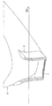
도 1은, 그 위에 장착되어 있는 종래 기술의 유체역학적 덕트를 갖춘 선박 선수의 부분 사시도이고, 여기에서 덕트는 수평방향 벽 부위, 및 수선 위에 뻗어 있는 것으로 나타나 있는 한 쌍의 측면방향 벽 부위들을 구비한다.
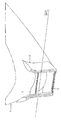
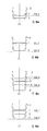
도 2는, 그 위에 장착되어 있는 본 발명의 유체역학적 덕트를 갖춘 선박 선수의 일 부분에 관한 사시도이고, 여기에서 덕트는 하측 수평방향 벽 부위, 상측 수평방향 벽 부위, 및 수선 위에 뻗어 있는 것으로 나타나 있는 측면방향 벽 부위들로 이루어져 있다.
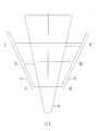
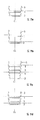
도 3은 본 발명의 유체역학적 덕트를 갖춘 선박 선수의 단면이며, 이는 하측 벽 부위, 상측 벽 부위와 수평방향으로 뻗어 있는 중간 벽 부위, 및 수평방향 벽 부위들의 단부들에 연결되어 있는 측면방향 부위들을 구비하되, 측면방향 부위들은 선수의 측면 벽들로부터 일정한 이탈 각도로 위쪽을 향하여 뻗음에 따라 이탈하고 있다.
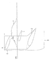
도 4는 본 발명의 유체역학적 덕트를 갖춘 선박의 일 부분에 관한 측면도이고, 이는 특히 저속 선박들을 위하여 사용되도록 의도되어 있는 한 쌍의 수평방향 벽 부위들, 즉 하측 및 상측 수평방향 벽 부위를 구비하고, 여기에서 상측 수평방향 벽 부위는 수선 위에 포지션조정되어 있다.
도 5는 본 발명의 유체역학적 덕트를 갖춘 선박의 일 부분에 관한 측면도이고, 이는 특히 고속 선박들을 위하여 사용되도록 의도되어 있는 한 쌍의 수평방향 벽 부위들, 즉 하측 및 상측 수평방향 벽 부위를 구비하고, 여기에서 상측 수평방향 벽 부위는 수선 아래에 포지션조정되어 있다.
도 6a 내지 도 6d에는, 본 발명의 유체역학적 덕트에 관한 단면도들이 저속 선박들의 선수에서의 설치를 위한 다수의 예시적 대체 실시예들로 나타나 있다.
도 7a 내지 도 7d에는, 본 발명의 유체역학적 덕트에 관한 단면도들이 고속 선박들의 선수에서의 설치를 위한 다수의 예시적인 대체 실시예들로 나타나 있다.
도 8은 노트(knot)로 되어 있는 선박의 명목 속도에 대한, 킬로와트(KW)로 되어 있는 선박의 추진을 위한 정격 마력에 관한 도표이고, 여기에서 라인 a는 유체역학적 덕트가 선수에 없는 선박의 경우이고, 라인 b는 종래 기술의 유체역학적 덕트가 선수에 있는 선박의 경우이고, 그리고 라인 c는 본 발명의 유체역학적 덕트가 그 선수에 장착되어 있는 선박의 경우이다.
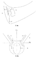
도 9a에는 본 발명의 일 실시예의 사시도가 나타나 있고, 여기에서 유체역학적 덕트는 구상형 선수를 갖춘 선박에 제공되어 있고, 하측 수평방향 벽 부위는 구상부의 상측 표면이고, 이에 반해 도 9b에는 구상형 선수를 갖춘 유체역학적 덕트의 조합에 관한 또 다른 실시예가 나타나 있고, 여기에서 하측 수평방향 벽 부위는 구상 본체의 어느 한쪽 측면 상에 선택된 높이로 뻗어 있다. 상측 수평방향 표면 파동 관리형 벽 부위는 어느 경우에나 수선에 근접하여 구상 본체 위에 위치되어 있다. BRIEF DESCRIPTION OF THE DRAWINGS The present invention is fully disclosed to the person skilled in the art with reference to the accompanying drawings, which are shown in a schematic but non-limiting way.
1 is a fragmentary perspective view of a ship bow with a prior art hydrodynamic duct mounted thereon, wherein the duct has a horizontal wall section and a pair of lateral wall sections shown extending above the waterline; do.
Figure 2 is a perspective view of a portion of a ship bow with the hydrodynamic duct of the present invention mounted thereon, wherein the duct is shown extending over the lower horizontal wall section, the upper horizontal wall section, and above the waterline; It consists of lateral wall sections.
3 is a cross-section of a vessel bow equipped with a hydrodynamic duct of the present invention, comprising a lower wall segment, an upper wall segment and a horizontally extending middle wall segment, and a lateral segment connected to the ends of the horizontal wall segments; , but the lateral parts are dislodging as they extend upwards at a certain angle of departure from the side walls of the athlete.
Fig. 4 is a side view of a part of a vessel equipped with a hydrodynamic duct of the present invention, which has a pair of horizontal wall sections which are intended to be used in particular for low-speed vessels, namely a lower and an upper horizontal wall section; and, here, the upper horizontal wall portion is positioned above the waterline.
Fig. 5 is a side view of a part of a vessel equipped with a hydrodynamic duct of the present invention, which has a pair of horizontal wall sections, i.e. a lower and an upper horizontal wall section, which are intended to be used in particular for high-speed vessels; and, here, the upper horizontal wall portion is positioned below the waterline.
6A-6D , cross-sectional views of the hydrodynamic duct of the present invention are shown in a number of exemplary alternative embodiments for installation at the bow of low-speed vessels.
7A-7D, cross-sectional views of the hydrodynamic duct of the present invention are shown in a number of exemplary alternative embodiments for installation at the bow of high-speed vessels.
8 is a diagram of the rated horsepower for propulsion of the vessel in kilowatts (KW) versus the vessel's nominal speed in knots, where line a is the vessel's fore without hydrodynamic ducting at the bow; case, line b is for a vessel in which the hydrodynamic duct of the prior art is mounted at its bow, and line c is for a vessel in which the hydrodynamic duct of the present invention is mounted at its bow.
9A is a perspective view of an embodiment of the present invention, wherein the hydrodynamic duct is provided on a vessel with a spherical bow, the lower horizontal wall portion is the upper surface of the spherical portion, whereas FIG. 9B shows a spherical Another embodiment of the combination of hydrodynamic ducts with bows is shown, wherein the lower horizontal wall portion extends to a selected height on either side of the spherical body. The upper horizontal surface wave management wall section is in any case located close to the waterline and above the spherical body.
본 발명의 도식적인 바람직한 실시예들은 첨부의 도면들을 참조해서 이하에 나타나 있을 것이다. Schematic preferred embodiments of the present invention will be shown below with reference to the accompanying drawings.
도 1에는, 선박(8)의 선수의 측면 벽들에 근접하여 뻗어 있는 한 쌍의 측면방향 벽 부위(5)들을 구비하는 종래 기술의 유체역학적 덕트가 나타나 있고, 여기에서 이들 측면방향 벽 부위(5)들의 바닥 단부는 수평방향으로 뻗어 있는 벽 부위(2)의 단부에 연결되어 있다. 1 shows a prior art hydrodynamic duct having a pair of
도 2에는 본 발명의 원주방향으로 폐쇄된 유체역학적 덕트의 도식적인 실시예가 나타나 있는데, 이는, 종래 기술의 수평방향으로 뻗어 있는 벽 부위(2)와 그 바닥에서 연결되어 있는 한 쌍의 측면방향 벽 부위(5)들의 전술된 구조적 요소들에 추가하여, 단부들 역시 위쪽을 향하여 뻗어 있는 측면방향 벽 부위(5)들에 연결되어 있는 상태에서 또 다른 수평방향으로 뻗어 있는 벽 부위(1)를 구비하고, 여기에서 수평방향으로 뻗어 있는 상측 벽 부위(1)는, 선박의 항해 동안 바다 표면에서의 파동의 효율적인 관리의 관점에서, 수선(waterline; WL)의 구역에 배열되어 있다. Figure 2 shows a schematic embodiment of a circumferentially closed hydrodynamic duct of the present invention, comprising a prior art horizontally extending
제안되는 수평방향으로 뻗어 있는 상측 벽 부위(1)는, 이 수평방향으로 뻗어 있는 벽 부위(1)의 선두 엣지를 통해 유동하는 파동의 속도의 점가를 만들어내기 위해서 바다 표면에서 파동들의 벡터들과 협력하며, 이러한 속도 점가는 압력 강하, 및 선박의 움직임에서 조우하게 되는 강하에 해당하는 저항들의 원하는 강하로 귀결된다. 표면 파동 관리가 있는 제안되는 수평방향으로 뻗어 있는 벽 부위(1)의 효과는 특히 중요하고, 그 효율성은 폭풍치는 바다의 상황들 하에서 상당히 점가되는 한편, 고요한 바다의 상황들 하에서 유동 벡터들은 선수 파동의 표면에 대해 대체로 평행하게 뻗어 있고, 폭풍치는 바다의 상황들 하에서 유동 벡터들은 달라지는 경사들로 다수의 달라지는 방향들을 가지며, 이러한 달라지는 유동 벡터들은 서로 상쇄하려는 경향이 있는 수직방향을 따라 뻗어 있는 벡터 성분들을 구비하지만, 그 존재는 선박의 움직임이 있는 방향으로 뻗어 있는 벡터 성분들의 세기의 감소로 귀결된다. 그러므로, 폭풍치는 바다의 상황들 하에서, 수평방향으로 뻗어 있는 벽 부위(1)와 감소된 세기를 가지면서 선박의 움직임이 있는 방향으로 뻗어 있는 유동 벡터들의 협력은 본 발명의 유체역학적 덕트의 실질적으로 개선된 성능으로 귀결된다. The proposed horizontally extending upper wall section (1) is combined with the vectors of waves at the sea surface to create a point value of the velocity of the wave flowing through the leading edge of this horizontally extending wall section (1). Working together, this speed increment results in a pressure drop and a desired drop in resistances corresponding to the drop encountered in the movement of the vessel. The effect of the proposed horizontally extending wall section (1) with surface wave management is particularly significant, and its effectiveness is significantly pointed out under stormy sea conditions, while under calm sea conditions the flow vectors are forward wave Running generally parallel to the surface of However, their presence results in a decrease in the intensity of the vector components extending in the direction of the movement of the vessel. Therefore, under stormy sea conditions, the cooperation of the horizontally extending
표면 파동의 관리가 있는 수평방향으로 뻗어 있는 벽 부위(1)를 포함하지 않는 종래 기술의 유체역학적 덕트에 비해 본 발명의 유체역학적 덕트의 개선된 성능은 도 8의 도표로부터 명확하게 자명하게 되어 있는데, 여기에는 폭풍치는 바다(4 보퍼트)의 상황 하에서 선박 속도(knot; 노트)에 대비되는 소모 전력(KW)이 나타나 있다. 도 8에는, 덕트없이 노출된 선체를 갖춘 선박의 경우(곡선 a), 표면 파동의 관리가 있는 상측 벽 부위가 없는 종래 기술의 덕트가 제공되어 있는 선박의 경우(곡선 b), 및 본 발명, 즉 표면 파동의 관리가 있는 상측 벽 부위를 추가적으로 구비하는 덕트가 제공되어 있는 선박의 경우(곡선 c)가 도시되어 있다. 위 도표는 벌크선(bulk carrier Sea Horse 35; 벌크 캐리어 시 호스 35)인 모형 선박을 가지고 포츠담 모형 수역(Potsdam Model Basin)에서 실시된 테스트들로부터 획득되었다. 이 마력 도표는, 13.5 노트의 항해 속도로 노출된 선체를 갖춘 선박(곡선 a)에 대비하여 14.70%의 백분율로 전력 소모의 감소를 제공하는 본 발명의 덕트(곡선 c)를 이용한 개선을 명확하게 묘사한다. 종래 기술의 덕트(곡선 b)는 또한 노출된 선체를 갖춘 동일한 선박(곡선 a)과 비교하여 개선을 보여주지만, 13.5 노트의 동일한 속도로 항해하는 선박과는 6.07%의 백분율로 실질적으로 점감되어 있다. 따라서, 위 도식적인 도표는, 본 발명에 개시되어 있는 바와 같이 표면 파동의 관리가 있는 추가적인 수평방향으로 뻗어 있는 벽 부위가 제공되어 있는 유체역학적 덕트의 효율성에서의 개선을 명확하게 묘사한다. The improved performance of the hydrodynamic duct of the present invention compared to the hydrodynamic duct of the prior art which does not include a horizontally extending
이상에서 언급된 바와 같이, 유체역학적 덕트의 성능에서의 상당한 개선은 선박이 상대적으로 더 상위의 속도 한계들로 항해하는 상태에서 폭풍치는 바다 상황들 하에서 획득된다. 이점에 있어서, 전술된 테스트에서의 모형의 항해 속도가 실제로 더 상위의 한계들의 구역에 있었다는 점, 즉 13.5 노트의 값을 가졌다는 점에 주목한다. 본 명세서에서, 본 발명의 유체역학적 덕트가 있는 이것과 같이 선수 상에 조파 저항들의 관리를 제공할 수 있는 수단의 부존재로 여러번 그러하고 이로써 동시다발적인 연료 감소를 달성할 수 없다는 점에 주목해야만 하며, 이는 그 잠재적인 연료 소모에 대해 열위의 속도로 항행하는 선박을 가지는 감소된 연료 소모를 가지기 위하여 결정될 수 있는데, 예컨대 11 노트 내지 12.5 노트 가량의 하위의 속도들에서 현재의 테스트가 있는 선박을 위하여 그러하다. 이 감소는 실제로 연료와 비용의 일정한 절감으로 귀결되지만, 이 절감은 선박의 점가되는 작동상 비용들 때문에 부분적으로 무력화되고, 아마도 전술된 감소된 속도에서 비경쟁적인 용선계약을 보여주게 되는데, 이는 필연적으로 늘어난 배송 기간이 동반되기 때문이다. As mentioned above, significant improvements in the performance of hydrodynamic ducts are obtained under stormy sea conditions with the vessel sailing at relatively higher speed limits. In this regard, it is noted that the sailing speed of the model in the test described above was actually in the region of higher limits, ie it had a value of 13.5 knots. It should be noted herein that the hydrodynamic duct of the present invention is many times in the absence of a means capable of providing management of wave resistances on a bow like this one and thus cannot achieve simultaneous fuel reduction, This can be determined in order to have reduced fuel consumption with a vessel sailing at a speed inferior to its potential fuel consumption, eg for a vessel with current testing at lower speeds of around 11 knots to 12.5 knots. do. This reduction actually results in certain savings in fuel and cost, but this savings is in part negated by the escalating operational costs of the vessel, possibly showing uncompetitive charterers at the aforementioned reduced speeds, which inevitably This is because of the increased delivery time.
게다가, 다양한 이유로 새로운 화물 할당을 맡기 위하여 특정 항구로의 빨라진 도착이나 일정한 선적의 신속한 배송을 위해 선박의 빨라진 항행을 요구하는 것은 가능성있다. 이러한 경우들에서, 본 발명의 유체역학적 덕트의 존재는 최대 정격 속도에서의 선박의 항행을 허용하고, 항행의 상승된 속도로 인한 점가되는 연료 소모를 균형맞추는 상당한 연료 절감을 제공해준다. 그러므로, 본 발명의 덕트를 선박에 제공하는 것이 상당히 제한된 기간 내에 획득되는 연료 절감 때문에 매우 효율적인 것으로 증명된 유리한 수익성있는 투자를 조성한다는 점은 분명하다. Moreover, it is possible for a variety of reasons to require an accelerated voyage of a vessel for expedited delivery of certain shipments or expedited arrival to a particular port in order to undertake new cargo assignments. In such cases, the presence of the hydrodynamic duct of the present invention allows for navigation of the vessel at its maximum rated speed and provides significant fuel savings balancing the fuel consumption incurred due to the elevated speed of navigation. Therefore, it is clear that providing ships with the ducts of the present invention constitutes an advantageous and profitable investment which has proven to be very effective because of the fuel savings achieved in a fairly limited period of time.
도 4와 도 5는, 각각 저속 선박과 고속 선박을 위하여 특히 사용되도록 의도되어 있는 상측 수평방향 벽 부위(1)와 하측 수평방향 벽 부위(2)를 구비하는 본 발명의 유체역학적 덕트를 갖춘 선박(8)의 선수의 일 부분의 측면도이다. 4 and 5 show a vessel equipped with a hydrodynamic duct of the invention having an upper
도 4와 도 5에는 선수 파동(7)의 전개가 도식적으로 도시되어 있고, 그리고 저속 선박들을 위한 도 4의 상측 수평방향 벽 부위(1)는 수선(WL) 위에 포지션조정되어 있는 한편, 고속 선박들을 위한 도 5의 상측 벽 부위(1)는 수선(WL) 아래에 포지션조정되어 있다는 점에 주목한다. 본 발명에서, 저속 선박들은, 선수 파동이 선수에서 전방 수직선(6) 앞에, 즉 전방 수직선(6)의 상류에 현재되어 있는 광폭 선수 구성을 가지는 선박들을 포함하는 것으로 의미되는 한편, 고속 선박들은, 선수 파동이 선수에서 전방 수직선(6) 상에 그리고 그 후에, 즉 전방 수직선(6)의 하류에 현재되어 있는 소폭 선수 구성을 가지는 선박들을 포함하는 것으로 의미된다. 각각 저속 선박과 고속 선박을 위한 전술된 구성들에서, 수평방향으로 뻗어 있는 상측 벽 부위(1)는 바다 표면 선수 파동(7)의 벡터들과 협력하여 선수 파동을 감소시킨다는 관점에서 유리하게 작용하는데, 그 벡터들은 수평방향 성분과 수직방향 성분으로 분석되어 도 4와 도 5에 있는 표면 상에 도식적으로 나타나 있다. 4 and 5 schematically show the development of the
도 6a 내지 도 6d와, 도 7a 내지 도 7d에는 각각 저속 선박과 고속 선박을 위한 본 발명의 덕트에 관한 도식적인 실시예들이 도시되어 있다. 선박 설계시 선택되는 명목 속도는 선수 기하구성에 관한 것이고, 예시로서 벌크선, 일반적인 화물선, 탱커 등과 같은 광폭 선수 구성을 가지는 것이 일반적인 16 노트 미만의 적은 값들로 보통 세팅되는 한편, 예컨대 16 노트보다 높고 최대 약 30 노트까지의 더 높은 명목 속도 값들은 여객 선박, 요트 또는 컨테이너들을 실어나르는 선박들과 같은 소폭 선수 구성을 가지는 것이 일반적인 선박들을 위하여 선정된다. 6a to 6d and 7a to 7d show schematic embodiments of the duct of the invention for a low-speed vessel and a high-speed vessel, respectively. The nominal speed chosen when designing the ship relates to the bow geometry, eg having a wide bow configuration such as bulk carriers, general cargo ships, tankers, etc. is usually set to small values below 16 knots, while it is usually set to small values, e.g. higher than 16 knots. Higher nominal speed values, up to about 30 knots, are chosen for ships that typically have a narrow bow configuration, such as passenger ships, yachts or ships carrying containers.
도 6a 내지 도 6d와, 도 7a 내지 도 7d에는 본 발명의 유체역학적 덕트의 단면이 나타나 있고, 선수의 중심선(center line; CL), 중심선(CL)의 각각의 측면에 있는 측면방향 벽 부위(5)들이 도시되어 있고, 완전히 선적된 선박들(선적 상황)에 기인하는 수선(WL1) 및 미선적된 선박들(미선적된 상황)에 기인하는 수선(WL2)을 지시한다. 본 발명의 덕트의 도식적인 실시예들은 아래에 요약되어 있다. 6a to 6d and 7a to 7d show cross-sections of the hydrodynamic ducts of the present invention, the lateral wall portions on each side of the center line (CL) and center line (CL) of the bow ( 5) are shown and indicate repairs WL1 due to fully loaded vessels (shipment condition) and repairs WL2 due to unshipped vessels (unloaded condition). Schematic embodiments of the duct of the present invention are summarized below.
도 6a와 도 7a에는 선적된 상황에 있는 각각 저속의 선박과 고속의 선박을 위하여 사용되도록 의도되어 있는 본 발명의 덕트가 나타나 있다. 이 실시예들에서, 선수 상에 가해지는 압력의 관리는 잠겨 있는 하측 벽 부위(2)이 맡고 있는 한편, 표면 파동 관리는 상측 벽 부위(1)가 맡고 있는데, 그 상측 벽 부위는 각각 저속 선박들을 위해서는 선적된 상황에서의 수선(WL1) 위에 포지션조정되어 있고(도 6a) 고속 선박들을 위해서는 수선(WL1) 아래에 포지션조정되어 있다(도 7a). 선박이 미선적된 상황에 있는 경우, 수평방향으로 뻗어 있는 벽 부위들(1, 2) 양자 모두는 물 바깥쪽에 자리하고 있고, 이 상황에서 덕트는 그 어떤 경우이든 선박의 항행 파라미터들에 관한 어떠한 효과도 명백하게 미치진 않는다. 6a and 7a show the duct of the invention which is intended to be used for low-speed and high-speed vessels, respectively, in the loaded situation. In these embodiments, the management of the pressure on the bow is taken over by the submerged lower wall section (2), while the surface undulation management is in the upper wall section (1), each of which is a low-speed vessel. They are positioned above the waterline WL1 in the loaded condition (FIG. 6a) for ships, and are positioned below the waterline WL1 for high-speed vessels (FIG. 7A). If the vessel is in the unshipped situation, both the horizontally extending
도 6b와 도 7b에는 선적된 상황에 있는 각각 저속의 선박과 고속의 선박을 위하여 사용되도록 의도되어 있는 본 발명의 덕트가 나타나 있다. 이들 실시예들에서, 선수 상에 가해지는 압력의 관리는 잠겨 있는 하측 벽 부위(2)가 맡고 있는 한편, 표면 파동 관리는 각각 저속의 선박과 고속의 선박을 위하여 수선(WL1) 위와 아래에 포지션조정되어 있는 상측 벽 부위(1)가 맡고 있다. 선박이 미선적된 상황에 있는 경우, 벽 부위(1)는 수선 위 멀리에서 물 바깥쪽에 자리하고 있는데 반해, 수평방향 벽 부위(2)는 각각 저속 선박과 고속 선박을 위하여 미선적된 상황에서의 수선(WL2) 위와 아래에 거기에 가까이 포지션조정되어 있다. 따라서, 이 실시예에서, 벽 부위(2)는 표면 파동의 관리를 맡고, 그러므로 이 실시예의 덕트는 선적된 선박의 상황과 미선적된 선박의 상황 양자 모두에서 표면 파동을 관리할 수 있다. Figures 6b and 7b show the duct of the present invention, which is intended to be used for low-speed and high-speed vessels, respectively, in the loaded situation. In these embodiments, the management of the pressure on the bow is taken over by the submerged
각각 저속의 선박과 고속의 선박을 위한 도 6c와 도 7c에서, 본 발명의 덕트는 완전히 선적된 선박의 상황과 미선적된 선박의 상황 양자 모두에서 완전히 작동상태에 있을 수 있다. 이 경우 덕트는, 상측 벽 부위(1)와 하측 벽 부위(2) 사이에서 그 안에 있는 한 쌍의 중간 벽 부위들(3, 4)을 구비한다. 이 실시예에서 덕트는 수평방향으로 뻗어 있는 벽 부위들(1, 3)을 활용하여 선적된 상황에 있는 선박을 위하여 완전히 작동상태에 있는데, 벽 부위(1)가 표면 파동의 관리를 제공하고 있고 완전히 잠겨 있는 벽 부위(3)가 덕트를 통해 선수에 충격을 가하는 바다 유동에 의해 가해지는 압력들의 조종을 맡고 있는 상태에서 그러하다. 선적된 상황에 있는 선박의 이 경우에서, 밑에 있는 벽 부위들(2, 4)은, 더 매끄러운 유동 흐름들을 제공하면서 유동 폭풍을 상쇄하는 동작을 제공한다. 이 실시예의 덕트는 수평방향으로 뻗어 있는 벽 부위들(4, 2)을 활용하여 미선적된 상황에 있는 선박을 위하여 완전히 작동상태에 있는 것으로 존속하고 있는데, 벽 부위(4)가 표면 파동의 관리를 제공하고 있고 완전히 잠겨 있는 벽 부위(2)가 덕트를 통해 선수에 충격을 가하는 바다 유동에 의해 가해지는 압력들의 조종을 맡고 있는 상태에서 그러하다. 미선적된 상황에 있는 선박의 이 경우에서, 벽 부위들(4, 2) 위에 놓여 있는 벽 부위들(1, 3)은 물 바깥쪽에 자리하고 있다. 6c and 7c for the low-speed vessel and the high-speed vessel respectively, the duct of the present invention can be fully operational both in the situation of a fully loaded vessel and the situation of an unshipped vessel. The duct in this case has a pair of
마지막으로, 도 6d와 도 7d에는, 각각 저속 선박과 고속 선박에서 사용되는 바와 같은 본 발명의 덕트에 관한 또 다른 실시예가 도시되어 있다. 이 실시예의 덕트는 벽 부위들(1, 2) 사이에서 그 안에 있는 수평방향으로 뻗어 있는 중간 벽 부위(3)를 구비한다. 선박이 선적된 상황에 있는 상태에서, 덕트는 완전히 작동상태에 있는데, 수평방향으로 뻗어 있는 벽 부위들(1, 3)이 덕트로 들어가는 유동에 의해 가해지는 압력들의 관리 및 표면 파동 관리를 제공하는 상태에서 그러하고, 밑에 있는 벽 부위(2)가 더 매끄러운 유동 흐름들을 달성해내면서 유동 폭풍을 상쇄하는 것을 제공하는 상태에서 각각 그러하다. 미선적된 상황에서, 벽 부위들(1, 3, 2)은 저속 선박들을 위하여 물 바깥쪽에 자리하고 있는데(도 6d), 벽 부위(2)가 미선적된 상황에서의 수선(WL2) 가까이에 위치되어 있으면서 본 발명에 개시되어 있는 표면 파동의 관리를 맡고 있는 상태에서 그러하다. 각각 고속 선박들을 위하여 미선적된 상황에서, 벽 부위들(1, 3)은 물 바깥쪽에 자리하고 있는 한편, 벽 부위(2)는 미선적된 상황에서의 수선(WL2) 가까이에서 물 안에 잠겨 있는 상태로 존속하고, 표면 파동의 관리를 맡는다. Finally, in Figures 6d and 7d another embodiment of the duct of the present invention as used in low-speed and high-speed vessels, respectively, is shown. The duct of this embodiment has a horizontally extending
도 3의 선박의 선수에 관한 단면으로 도시되어 있는 유체역학적 덕트는 상술된 도 6d와 도 7d에 나타나 있는 타입으로 되어 있는데, 하측 수평방향 벽 부위(AB), 상측 수평방향 벽 부위(EF) 및 중간 수평방향 벽 부위(CD)를 구비하고, 측면방향 벽 부위(5)가 벽 부위들((AB), (CD), (EF))의 단부들에 연결되어 있으며, 여기에서 이들 측면방향 벽 부위(5)들은 일정한 이탈 각도를 보여주는 선박(8)의 선수의 측면 벽들로부터 이탈하여 위쪽을 향하여 뻗어 있다. 본 발명의 바람직한 실시예에 따르면, 측면방향 벽 부위(5)들은 선수의 측면 벽들의 구성을 따르도록 구성되어 있고, 이로써 선수 측면 벽들에 대해 평행하게 뻗어 있을 수 있고, 측면방향 벽(5)들이 선수 측면 벽들로부터 이탈하고 있는 상태로 도 3에 도시되어 있는 실시예는 2개 이상의 수평방향으로 뻗어 있는 벽 부위들의 덕트와 조합하는 유리한 결과들을 제공해주는데, 이는 덕트를 통과하는 유동을 강화하는 것이 바람직한 상황들 하에서 그러하고, 그리고 이탈로 인한 이러한 상황들 하에서 일어나는 소용돌이들을 생성하는 가능성있는 바람직하지 않는 손실은 수평방향으로 뻗어 있는 벽 부위들의 여유 길이들의 벡터들의 보강된 동작에 의해 보상된다. The hydrodynamic duct, shown in cross section with respect to the bow of the vessel in Fig. 3, is of the type shown in Figs. 6d and 7d described above, with a lower horizontal wall section AB, an upper horizontal wall section EF and It has an intermediate horizontal wall section CD, the
측면방향 벽 부위(5)들의 이탈은 수정될 수 있어서, 측면방향 벽 부위(5)들 중 하나의 부분은 선수의 측면 벽들로부터의 일정한 이탈을 보여주는 구성으로 뻗어 있는 한편, 측면방향 벽 부위(5)들의 또 다른 부분은 선수의 측면 벽들에 대해 그 전술된 평행한 배향을 유지하는 구성으로 뻗어 있다. 예시로서, 측면방향 벽 부위(5)들의 부분들((AC), (BD))은 선수의 측면 벽들의 구성을 따를 수 있는 한편 지점들((C), (D)) 위에 뻗어 있는 측면방향 벽 부위(5)들의 부분들은 선수의 측면 벽들로부터 이탈하도록 배열될 수 있고, 또는 그 반대의 경우도 마찬가지이며, 측면방향 벽 부위들의 부분들((AC), (BD))은 선수의 측면 벽들로부터 이탈할 수 있는 한편, 지점들((C), (D)) 위에 포지션조정되어 있는 부분들은 선수의 구성을 따르면서 선수 측면 벽들에 대해 평행하게 유지되어 있다. 대체적으로, 선수 측면 벽들에 대해 상대적으로 측면방향 벽 부위들의 이탈된 배향과 평행한 배향의 임의의 조합은 가능성있고, 선박의 항행에 관한 특징들과 명세서들이 취하고 있는 요건들과 대응관계에 있는 달라지는 환경들 하에서 바람직할 수 있다. 본 명세서에서, 도 6d나 도 7d에 도시되어 있는 실시예와 관련된 전술된 조합들이 도 6a나 도 7a, 도 6b나 도 7b, 그리고 도 6c나 도 7c의 실시예들에서 유사하게 적용가능하다는 점에 주목한다. The deviation of the
도 9a와 도 9b에는 구상부(9)와 조합하여 선박들의 선수 상에 장착되는 본 발명의 유체역학적 덕트의 실시예들이 도시되어 있다. 특히, 도 9a에는 본 발명의 일 실시예의 사시도가 나타나 있고, 여기에서 유체역학적 덕트는 구상형 선수에 제공되어 있고, 하측 수평방향 벽 부위는 구상 본체(9)의 상측 표면인데 반해, 도 9b에는 구상형 선수를 갖춘 유체역학적 덕트의 조합에 관한 또 다른 실시예가 나타나 있고, 여기에서 하측 수평방향 벽 부위(2)는 구상 본체(9)의 어느 한쪽 측면 상에 선택된 높이로 뻗어 있다. 측면방향 벽 부위(5)들은 어느 경우에나 선수 및/또는 구상부(9)의 측면 벽들의 어느 한쪽 측면 상에 뻗어 있고, 상측 수평방향 표면 파동 관리형 벽 부위(1)는 어느 경우에나 수선에 근접하여 구상 본체(9) 위에 위치되어 있다. 9a and 9b show embodiments of the hydrodynamic duct of the invention which are mounted on the bow of ships in combination with a
본 명세서에서, 본 발명의 설명이 도식적이되 제한적이지 않은 실시예들을 참조하여 나타나 있다는 점에 주목해야만 한다. 그러므로, 형상, 크기, 기술구성, 치수들, 재료들, 어셈블리와 기술구성의 구성요소와 보조 메커니즘뿐만 아니라, 달라지는 명목 항행 속도들과 달라지는 선수 기하구성을 가지는 상이한 타입들의 선박들과 기능적인 상호의존관계에 있는 선박의 선수에 장착되는 유체역학적 덕트의 설계 파라미터들에 관한 임의의 수정이나 변경은 아래의 청구범위에 요약된 바와 같이 본 발명의 범위와 목표의 일부로 여겨진다. It should be noted that, herein, the description of the invention has been presented with reference to illustrative, but not restrictive, embodiments. Therefore, functional interdependence with different types of vessels having varying nominal sail speeds and varying bow geometries, as well as components and auxiliary mechanisms of shape, size, construction, dimensions, materials, assembly and construction, and functional interdependence. Any modifications or changes to the design parameters of the hydrodynamic duct mounted on the bow of the ship concerned are considered part of the scope and aim of the present invention as outlined in the claims below.
Claims (9)
상기 유체역학적 덕트는 적어도 하나의 추가적인 수평방향 벽 부위가 더 제공되어 있고, 상기의 수평방향 벽 부위는 수선의 구역에서 상기의 수평방향 벽 부위(2) 위에 포지션조정되도록 배열되어 있되 상기의 추가적인 수평방향 벽 부위의 선두 엣지를 통한 유동의 점가된 속도의 결과로서 만들어지는 파동 에너지의 흡수를 만들어내도록 제작되어 있고,
상기의 수평방향 벽 부위(2)의 단부들에 연결되어 있으면서 상기의 적어도 하나의 추가적인 수평방향 벽 부위의 단부들에 연결되어 있되 선수의 어느 한쪽 측면 상에서 위쪽을 향하여 뻗어 있는 상기 측면방향 벽 부위(5)들과 함께, 수선의 구역에 상기의 적어도 하나의 추가적인 수평방향 벽 부위를 갖춘 상기 덕트의 바닥에 있는 상기의 수평방향 벽 부위(2)의 조합은, 조파 저항들의 점증적으로 점가되는 감소 및 상기 선박의 추진을 위한 연료 소모와 정격 마력의 감소를 제공하는, 원주방향으로 폐쇄된 덕트를 정의하는 것을 특징으로 하는, 그 선수에서의 유동 관리가 있는 유체역학적 덕트를 갖춘 선박.A vessel having a hydrodynamic duct with flow management at its bow, said duct comprising a horizontal wall section (2) extending on either side of the centerline (CL) of the bow of said vessel (8), and Consists of a pair of lateral wall sections (5), each of said lateral wall sections (5) connected to one end of said horizontal wall section (2), said lateral wall sections (5) In a vessel, the bow forms, together with the horizontal wall section (2), an area in the interior of the duct that extends upwards on each side of the bow and is entirely differentiated from the flow outside the duct,
Said hydrodynamic duct is further provided with at least one additional horizontal wall section, said horizontal wall section being arranged to be positioned above said horizontal wall section (2) in the region of the waterline, said additional horizontal wall section being Constructed to produce absorption of wave energy created as a result of the pointed velocity of flow through the leading edge of the directional wall section;
said lateral wall section connected to the ends of said horizontal wall section (2) and connected to the ends of said at least one additional horizontal wall section, said lateral wall section extending upward on either side of the bow; 5), the combination of said horizontal wall section (2) at the bottom of said duct with said at least one additional horizontal wall section in the region of the waterline, together with a progressively progressive reduction of wave resistances and defining a circumferentially closed duct that provides a reduction in rated horsepower and fuel consumption for propulsion of the vessel.
상기의 적어도 하나의 추가적인 수평방향 벽 부위는, 상기 선박이 선적된 상황에 있는 경우 선적된 상황에서의 수선(WL1)의 구역에서 작동하도록 배열되어 있되 표면 파동들의 관리를 제공하도록 제작되어 있는, 수평방향 벽 부위(1)이고,
상기의 수평방향 벽 부위(1)는, 선수 파동들이 선수에서 전방 수직선(6) 앞에 그리고 그 상류에 현재되어 있는 광폭 선수 구성으로 선박들을 위하여 상기의 수선(WL1) 위에 포지션조정되고, 선수 파동들이 선수에서 전방 수직선(6) 상에 그리고 바로 그 하류에 현재되어 있는 소폭 선수 구성으로 선박들을 위하여 상기의 수선(WL1) 위에 포지션조정되는 것을 특징으로 하는, 그 선수에서의 유동 관리가 있는 유체역학적 덕트를 갖춘 선박.The method of claim 1,
wherein said at least one additional horizontal wall section is arranged to operate in the area of the water line WL1 in the loaded condition when the vessel is in the loaded condition and is adapted to provide management of surface undulations. directional wall area (1),
Said horizontal wall section (1) is positioned above said waterline (WL1) for ships in a wide bow configuration in which bow waves are present in front and upstream of a forward vertical line (6) at the bow, and the bow waves are Hydrodynamic duct with flow management at its bow, characterized in that it is positioned above the waterline (WL1) for ships in a narrow bow configuration present on and immediately downstream of the forward vertical line (6) at the bow ships equipped with
상기의 적어도 하나의 추가적인 수평방향 벽 부위는, 상기 선박이 미선적된 상황에 있는 동안에는 상기의 수평방향 벽 부위들(1, 2) 양자 모두가 미선적된 상황에서의 수선(WL2) 위에서 물 바깥쪽에 자리하고 있도록 배열되어 있고 그리고 상기 덕트가 상기 선박의 항행 파라미터들에 관한 어떠한 효과도 미치지 않도록 배열되어 있는, 수평방향 벽 부위(1)인 것을 특징으로 하는, 그 선수에서의 유동 관리가 있는 유체역학적 덕트를 갖춘 선박.The method of claim 1,
Said at least one additional horizontal wall section is out of the water above the waterline WL2 in an unshipped condition in which both said horizontal wall sections 1 , 2 are out of the water while the vessel is in an unshipped condition. Fluid with flow management at its bow, characterized in that it is a horizontal wall section (1), arranged to lie on the side and arranged such that the duct has no effect on the navigation parameters of the vessel. Vessels equipped with mechanical ducts.
상기의 적어도 하나의 추가적인 수평방향 벽 부위는, 상기 선박이 미선적된 상황에 있는 경우에는 상기 수평방향 벽 부위(1)가 미선적된 상황에서의 수선(WL2) 위에서 물 바깥쪽에 자리하고 있도록 배열되어 있고 그리고 상기 수평방향 벽 부위(2)가 미선적된 상황에서의 수선(WL2)의 구역에 포지션조정되어 있으면서 표면 파동들의 관리를 맡도록 배열되어 있는, 수평방향 벽 부위(1)인 것을 특징으로 하는, 그 선수에서의 유동 관리가 있는 유체역학적 덕트를 갖춘 선박.The method of claim 1,
Said at least one additional horizontal wall section is arranged such that, in the case of the vessel in the unshipped condition, the horizontal wall section 1 lies out of the water above the waterline WL2 in the unshipped condition. and wherein said horizontal wall section (2) is positioned in the region of the waterline (WL2) in an unshipped situation and is arranged to take charge of the management of surface waves. A vessel equipped with a hydrodynamic duct with flow management at its bow.
상기 유체역학적 덕트는, 상기의 수평방향으로 뻗어 있는 벽 부위들(1, 2) 사이에서 그 안에 있는, 수평방향으로 뻗어 있는 중간 벽 부위(3)를 포함하고 있고,
상기 선박이 선적된 상황에 있는 경우, 상기 덕트는 다음의 상태, 즉:
상기 수평방향으로 뻗어 있는 벽 부위(1)가 상기 덕트의 정상에서 표면 파동들을 관리하고 있는 상태로서, 상기의 수평방향으로 뻗어 있는 벽 부위(1)는, 선수 파동들이 선수에서 전방 수직선(6) 앞에 그리고 그 상류에 현재되어 있는 광폭 선수 구성으로 선박들을 위하여 상기의 선적된 상황 수선(WL1) 위에 포지션조정되고, 선수 파동들이 선수에서 전방 수직선(6) 상에 그리고 바로 그 하류에 현재되어 있는 소폭 선수 구성으로 선박들을 위하여 상기의 선적된 상황 수선(WL1) 아래에 포지션조정되는, 상태;
상기의 수평방향으로 뻗어 있는 벽 부위들(1, 2) 사이에서 그 안에 위치되어 있는 상기 수평방향으로 뻗어 있는 중간 벽 부위(3)가 상기 덕트의 바닥에 가해지고 있는 압력을 관리하도록 제작되어 있는 상태; 및
상기의 수평방향으로 뻗어 있는 중간 벽 부위(3) 아래에 위치되어 있는 상기 수평방향으로 뻗어 있는 벽 부위(2)가 층류 조절을 제공하도록 제작되어 있는 상태;
에서 작동하는 것을 특징으로 하는, 그 선수에서의 유동 관리가 있는 유체역학적 덕트를 갖춘 선박.The method of claim 1,
said hydrodynamic duct comprises a horizontally extending intermediate wall section (3) therein between said horizontally extending wall sections (1, 2),
When the vessel is in a loaded condition, the duct must be:
The horizontally extending wall section (1) is the state in which the surface waves are managed at the top of the duct, the horizontally extending wall section (1) is that the bow waves are forward vertical line (6) at the bow. For ships with a wide bow configuration present in front and upstream of it, a small width with bow waves present on the forward vertical line 6 and immediately downstream from the bow, positioned above the loaded condition water WL1 above. condition, positioned below the loaded condition repair (WL1) above for ships in a bow configuration;
wherein said horizontally extending intermediate wall section (3) located therein between said horizontally extending wall sections (1, 2) is adapted to manage the pressure exerted on the bottom of said duct. state; and
wherein said horizontally extending wall section (2) located below said horizontally extending intermediate wall section (3) is adapted to provide laminar flow control;
A vessel equipped with a hydrodynamic duct with flow management at its bow, characterized in that it operates in
상기 유체역학적 덕트는, 상기의 수평방향으로 뻗어 있는 벽 부위들(1, 2) 사이에서 그 안에 있는, 수평방향으로 뻗어 있는 중간 벽 부위(3)를 포함하고 있고,
상기 선박이 미선적된 상황에 있는 경우, 상기 덕트는, 상기 수평방향으로 뻗어 있는 벽 부위들(1, 3)이 물 바깥쪽에 자리하고 있는 상태에서 작동하고 그리고 상기 수평방향으로 뻗어 있는 벽 부위(2)가 미선적된 상황에서의 수선(WL2)의 구역에서 표면 파동들의 관리를 제공하도록 제작되어 있는 상태에서 작동하고,
상기의 수평방향으로 뻗어 있는 벽 부위(2)는, 선수 파동들이 선수에서 상기 전방 수직선(6) 앞에 그리고 그 상류에 현재되어 있는 광폭 선수 구성으로 선박들을 위하여 상기의 미선적된 상황 수선(WL2) 위에 포지션조정되고, 선수 파동들이 선수에서 상기 전방 수직선(6) 상에 그리고 바로 그 하류에 현재되어 있는 소폭 선수 구성으로 선박들을 위하여 상기의 미선적된 상황 수선(WL2) 아래에 포지션조정되는 것을 특징으로 하는, 그 선수에서의 유동 관리가 있는 유체역학적 덕트를 갖춘 선박.The method of claim 1,
said hydrodynamic duct comprises a horizontally extending intermediate wall section (3) therein between said horizontally extending wall sections (1, 2),
In case the vessel is in an unshipped condition, the duct operates with the horizontally extending wall sections 1 , 3 situated outside the water and the horizontally extending wall section ( 2) operates in the condition that it is constructed to provide management of surface undulations in the area of the waterline WL2 in an unshipped situation;
Said horizontally extending wall section (2) is the above unshipped condition repair (WL2) for ships in a wide bow configuration in which bow waves are present at the bow in front of and upstream of the forward vertical line (6). Positioned above and below said unshipped condition waterline (WL2) for ships in a narrow bow configuration where bow waves are present at the bow on and immediately downstream of the forward vertical line (6). A vessel equipped with a hydrodynamic duct with flow management at its bow.
상기 유체역학적 덕트는, 상기 수평방향으로 뻗어 있는 벽 부위(1) 아래에 포지션조정되어 있는 수평방향으로 뻗어 있는 중간 벽 부위(3), 및 상기 수평방향으로 뻗어 있는 벽 부위(2) 위에 그리고 상기 수평방향으로 뻗어 있는 벽 부위(3) 아래에 포지션조정되어 있는 수평방향으로 뻗어 있는 추가적인 벽 부위(4)를 포함하고 있고,
상기 선박이 선적된 상황에 있는 경우, 상기 덕트는 다음의 상태, 즉:
상기 수평방향으로 뻗어 있는 벽 부위(1)가 상기 덕트의 정상에서 표면 파동들을 관리하고 있는 상태로서, 상기의 수평방향으로 뻗어 있는 벽 부위(1)는, 선수 파동들이 선수에서 전방 수직선(6) 앞에 그리고 그 상류에 현재되어 있는 광폭 선수 구성으로 선박들을 위하여 상기의 선적 상황 수선(WL1) 위에 포지션조정되고, 선수 파동들이 선수에서 전방 수직선(6) 상에 그리고 바로 그 하류에 현재되어 있는 소폭 선수 구성으로 선박들을 위하여 상기의 선적 상황 수선(WL1) 아래에 포지션조정되는, 상태;
상기 수평방향으로 뻗어 있는 벽 부위(3)가 상기 덕트의 바닥에 가해지고 있는 압력을 관리하도록 제작되어 있는 상태; 및
상기의 수평방향으로 뻗어 있는 벽 부위(3) 아래에 위치되어 있는 상기 수평방향으로 뻗어 있는 벽 부위(4)가 층류 조절을 제공하도록 제작되어 있는 상태;
에서 작동하는 것을 특징으로 하는, 그 선수에서의 유동 관리가 있는 유체역학적 덕트를 갖춘 선박.The method of claim 1,
The hydrodynamic duct comprises a horizontally extending intermediate wall section (3) positioned below the horizontally extending wall section (1), and over the horizontally extending wall section (2) and said a further horizontally extending wall section (4) positioned below the horizontally extending wall section (3);
When the vessel is in a loaded condition, the duct must be:
The horizontally extending wall section (1) is the state in which the surface waves are managed at the top of the duct, the horizontally extending wall section (1) is that the bow waves are forward vertical line (6) at the bow. A narrow bow with bow waves present on and immediately downstream of the forward vertical line (6) at the bow, positioned above the above shipping situation normal (WL1) for ships with the wide bow configuration present in front and upstream thereof. condition, positioned below the shipping situation repair (WL1) above for ships in configuration;
a state in which the horizontally extending wall section (3) is made to manage the pressure applied to the bottom of the duct; and
wherein said horizontally extending wall section (4) located below said horizontally extending wall section (3) is adapted to provide laminar flow control;
A vessel equipped with a hydrodynamic duct with flow management at its bow, characterized in that it operates in
상기 유체역학적 덕트는, 상기 수평방향으로 뻗어 있는 벽 부위(1) 아래에 포지션조정되어 있는 수평방향으로 뻗은 추가적인 벽 부위(3), 및 상기의 수평방향으로 뻗어 있는 벽 부위들(2, 3) 사이에서 그 안에서 상기 수평방향으로 뻗어 있는 벽 부위(3) 아래에 포지션조정되어 있는 수평방향으로 뻗어 있는 추가적인 벽 부위(4)를 포함하고 있고,
상기 선박이 미선적된 상황에 있는 경우, 상기 수평방향으로 뻗어 있는 벽 부위들(1, 3)은 물 바깥쪽에 자리하고 있고, 상기 덕트는 다음의 상태, 즉:
상기 수평방향으로 뻗어 있는 벽 부위(4)가 상기 덕트의 정상에서 표면 파동들을 관리하고 있는 상태로서, 상기의 수평방향으로 뻗어 있는 벽 부위(4)는, 선수 파동들이 선수에서 전방 수직선(6) 앞에 그리고 그 상류에 현재되어 있는 광폭 선수 구성으로 선박들을 위하여 상기의 미선적된 상황 수선(WL2) 위에 포지션조정되고, 선수 파동들이 선수에서 전방 수직선(6) 상에 그리고 바로 그 하류에 현재되어 있는 소폭 선수 구성으로 선박들을 위하여 상기의 미선적된 상황 수선(WL2) 아래에 포지션조정되는, 상태;
상기 수평방향으로 뻗어 있는 벽 부위(2)가 상기 덕트의 바닥에 가해지고 있는 압력을 관리하도록 제작되어 있는 상태;
에서 작동하는 것을 특징으로 하는, 그 선수에서의 유동 관리가 있는 유체역학적 덕트를 갖춘 선박.The method of claim 1,
The hydrodynamic duct comprises a further horizontally extending wall section (3) positioned below the horizontally extending wall section (1), and said horizontally extending wall sections (2, 3) a further horizontally extending wall section (4) positioned between said horizontally extending wall sections (3) therein;
When the vessel is in an unshipped condition, the horizontally extending wall sections 1 , 3 lie outside the water, and the duct is in the following condition:
The horizontally extending wall section (4) is a condition in which the surface waves are managed at the top of the duct, the horizontally extending wall section (4) is that the bow waves are forward vertical (6) at the bow. Positioned above the unshipped condition water WL2 above for ships in the wide bow configuration present in front and upstream thereof, the bow waves present at the bow on the forward vertical line 6 and immediately downstream condition, repositioned below the above unshipped condition repair (WL2) for ships in a narrow bow configuration;
a state in which the horizontally extending wall portion (2) is manufactured to manage the pressure applied to the bottom of the duct;
A vessel equipped with a hydrodynamic duct with flow management at its bow, characterized in that it operates in
상기 유체역학적 덕트의 상기 측면방향 벽 부위(5)들은:
상기 측면방향 벽 부위(5)들의 후미 엣지가 수선의 각각의 특정 레벨에서 상기 선박(8)의 선수의 측면 벽들로부터 일정한 같은 거리로 유지되어 있는 상태에서, 그것들에 대해 평행하게 존속하고 있는 상기 선박(8)의 선수의 측면 벽들의 구성을 따르도록; 배열되어 있기도 하고, 또는
고정된 이탈 각도 또는 가변적인 이탈 각도 중 어느 하나로 상기 선박(8)의 선수의 측면 벽들로부터 이탈하도록; 배열되어 있기도 하고, 또는
그 길이의 일부가 상기 덕트의 높이의 상측 부위 또는 하측 부위 중 어느 하나를 따라 고정된 이탈 각도 또는 가변적인 이탈 각도로 이탈하도록 상기의 측면방향 벽 부위(5)들이 배열되어 있고, 그리고 그것들에 대해 평행하게 존속하고 있으면서 선수의 측면 벽들의 구성을 따르고 있는 상기 선박(8)의 선수의 측면 벽들로부터 상기의 고정된 거리로 상기의 측면방향 벽 부위(5)들의 또 다른 부분이 배열되어 있도록; 배열되어 있기도 하는
것을 특징으로 하는, 그 선수에서의 유동 관리가 있는 유체역학적 덕트를 갖춘 선박.The method of claim 1,
The lateral wall sections 5 of the hydrodynamic duct are:
The vessel remaining parallel to them, with the aft edge of the lateral wall sections 5 maintained at a constant equal distance from the side walls of the bow of the vessel 8 at each particular level of waterline (8) to conform to the construction of the player's side walls; are arranged, or
to deviate from the side walls of the bow of the vessel (8) at either a fixed departure angle or a variable departure angle; are arranged, or
The lateral wall sections 5 are arranged such that part of their length departs with a fixed or variable departure angle along either the upper part or the lower part of the height of the duct, and with respect to them so that another part of said lateral wall sections (5) is arranged at said fixed distance from the side walls of the bow of the vessel (8) which remain parallel and follow the construction of the side walls of the bow; also arranged
A vessel equipped with a hydrodynamic duct with flow management in its bow.
Applications Claiming Priority (3)
| Application Number | Priority Date | Filing Date | Title |
|---|---|---|---|
| GR20190100102 | 2019-02-28 | ||
| GR20190100102A GR20190100102A (en) | 2019-02-28 | 2019-02-28 | Ship equipped with a bow hydrodynamic flow management conduit furnished with a horizontal wawing management blade |
| PCT/GR2020/000016 WO2020174256A1 (en) | 2019-02-28 | 2020-02-28 | Vessel with a hydrodynamic duct of flow management mounted on the bow thereof with a horizontal wall portion of surface wave management |
Publications (1)
| Publication Number | Publication Date |
|---|---|
| KR20220002270A true KR20220002270A (en) | 2022-01-06 |
Family
ID=70110272
Family Applications (1)
| Application Number | Title | Priority Date | Filing Date |
|---|---|---|---|
| KR1020217030154A KR20220002270A (en) | 2019-02-28 | 2020-02-28 | Vessels with hydrodynamic ducts with flow management mounted on their bow with horizontal wall sections with surface wave management |
Country Status (8)
| Country | Link |
|---|---|
| US (1) | US20220135183A1 (en) |
| EP (1) | EP3931073A1 (en) |
| JP (1) | JP2022522026A (en) |
| KR (1) | KR20220002270A (en) |
| CN (1) | CN113677590A (en) |
| AU (1) | AU2020227267A1 (en) |
| GR (1) | GR20190100102A (en) |
| WO (1) | WO2020174256A1 (en) |
Family Cites Families (16)
| Publication number | Priority date | Publication date | Assignee | Title |
|---|---|---|---|---|
| US1258554A (en) * | 1917-04-13 | 1918-03-05 | Albert W Furness | Current-deflector for marine vessels. |
| DE682004C (en) * | 1936-11-20 | 1939-10-06 | Samuel White & Company Ltd J | Watercraft with hydrofoils |
| US3651775A (en) * | 1969-08-18 | 1972-03-28 | Helmut Kock | Hydrofoil system |
| GR1000797B (en) * | 1991-06-10 | 1993-01-25 | Emmanouil E Petromanolakis | Wave-making energy absorber during vessel s propulsion |
| GR1007178B (en) | 1995-02-22 | 2011-01-31 | Πετρομανωλακης Εμμ. | Ship's stem duct with airfoil section. |
| US5566634A (en) * | 1995-02-22 | 1996-10-22 | Petromanolakis; Emanuel E. | Ship's stem duct with airfoil section |
| JPH1120775A (en) * | 1997-07-01 | 1999-01-26 | Nkk Corp | Craft with hydrofoil |
| US7191725B2 (en) * | 2004-04-30 | 2007-03-20 | Navatek, Ltd. | Bow lifting body |
| JP2012162116A (en) * | 2011-02-03 | 2012-08-30 | Unjo Senpaku Kogyo Kk | Wave shock relieving device |
| GR1007687B (en) * | 2011-07-18 | 2012-09-12 | Εμμανουηλ Ευαγγελου Πετρομανωλακης | Hydrodynamic duct for the water flow management at the ship's prow |
| KR20130055994A (en) * | 2011-11-21 | 2013-05-29 | 에스티엑스조선해양 주식회사 | Lift ring for ships to reduce wave making resistance around bow |
| GR20120100643A (en) * | 2012-12-12 | 2014-07-18 | Εμμανουηλ Ευαγγελου Πετρομανωλακης | Boat furnished with a bow hydrodynamic flow management duct |
| KR20160027545A (en) * | 2014-09-01 | 2016-03-10 | 현대중공업 주식회사 | Ship |
| KR20160149747A (en) * | 2015-06-19 | 2016-12-28 | 현대중공업 주식회사 | A Variable Hydrofoil For Bow Wave Control |
| JP6646294B2 (en) * | 2015-07-24 | 2020-02-14 | 国立研究開発法人 海上・港湾・航空技術研究所 | Drag-reducing bow shape with valve attachment and ship with drag-reducing bow shape |
| US10017227B2 (en) * | 2016-12-13 | 2018-07-10 | Naviform Consulting & Research Ltd. | Minimum wave bow |
-
2019
- 2019-02-28 GR GR20190100102A patent/GR20190100102A/en unknown
-
2020
- 2020-02-28 EP EP20716179.5A patent/EP3931073A1/en active Pending
- 2020-02-28 KR KR1020217030154A patent/KR20220002270A/en unknown
- 2020-02-28 WO PCT/GR2020/000016 patent/WO2020174256A1/en unknown
- 2020-02-28 AU AU2020227267A patent/AU2020227267A1/en active Pending
- 2020-02-28 CN CN202080028421.9A patent/CN113677590A/en active Pending
- 2020-02-28 US US17/434,047 patent/US20220135183A1/en active Pending
- 2020-02-28 JP JP2021550309A patent/JP2022522026A/en active Pending
Also Published As
| Publication number | Publication date |
|---|---|
| WO2020174256A1 (en) | 2020-09-03 |
| WO2020174256A9 (en) | 2021-09-23 |
| GR20190100102A (en) | 2020-09-16 |
| JP2022522026A (en) | 2022-04-13 |
| EP3931073A1 (en) | 2022-01-05 |
| CN113677590A (en) | 2021-11-19 |
| US20220135183A1 (en) | 2022-05-05 |
| AU2020227267A1 (en) | 2021-10-07 |
Similar Documents
| Publication | Publication Date | Title |
|---|---|---|
| RU2597430C2 (en) | Hydrodynamic channelling nozzle for controlling flow on ship bow | |
| US10293886B2 (en) | Watercraft vessel with a planing hull | |
| JP6697786B2 (en) | Ship front side design | |
| JP6541575B2 (en) | A ship with hydrodynamic bow fins arrangement for water flow deflection | |
| WO2014042127A1 (en) | Commercial cargo ship | |
| EP2110311B1 (en) | Finned rudder | |
| EP2029420B1 (en) | Vessel provided with a foil below the waterline | |
| JP6687673B2 (en) | Vessels with low wind resistance | |
| KR20220002270A (en) | Vessels with hydrodynamic ducts with flow management mounted on their bow with horizontal wall sections with surface wave management | |
| Souppez et al. | Hydrofoil configurations for sailing superyachts: Hydrodynamics, stability and performance | |
| RU2797708C2 (en) | Ship with a hydrodynamic flow control channelling nozzle installed on its bow, having a horizontal wall section for surface wave control | |
| US9751593B2 (en) | Wave piercing ship hull | |
| US20150291257A1 (en) | Planing hydrofoils for marine craft | |
| CN113165723B (en) | Ship body with raised part in bottom side area | |
| JP2006008091A (en) | Vessel shape for small high speed vessel | |
| KR20240040341A (en) | Stern skeg of vessel and vessel including the same | |
| KR100544899B1 (en) | The type of ship with airpoil-fin | |
| CA3225783A1 (en) | Marine vessel flow modifying device | |
| NL2006538C2 (en) | Round-bilge hull form with bulbous bow, spray rails and dynamic trim control for high speed. | |
| JP2008049988A (en) | High speed fishing boat | |
| JP2009255717A (en) | High-speed boat |