KR20210141618A - Liquefied gas storage structure and liquefied gas carrier - Google Patents
Liquefied gas storage structure and liquefied gas carrier Download PDFInfo
- Publication number
- KR20210141618A KR20210141618A KR1020217033718A KR20217033718A KR20210141618A KR 20210141618 A KR20210141618 A KR 20210141618A KR 1020217033718 A KR1020217033718 A KR 1020217033718A KR 20217033718 A KR20217033718 A KR 20217033718A KR 20210141618 A KR20210141618 A KR 20210141618A
- Authority
- KR
- South Korea
- Prior art keywords
- tank
- support member
- liquefied gas
- inner tank
- storage structure
- Prior art date
Links
- 239000000463 material Substances 0.000 claims description 41
- 239000011810 insulating material Substances 0.000 claims description 20
- 238000000034 method Methods 0.000 claims description 10
- 239000007789 gas Substances 0.000 description 49
- 230000035515 penetration Effects 0.000 description 11
- IJGRMHOSHXDMSA-UHFFFAOYSA-N Atomic nitrogen Chemical compound N#N IJGRMHOSHXDMSA-UHFFFAOYSA-N 0.000 description 7
- 239000001257 hydrogen Substances 0.000 description 6
- 229910052739 hydrogen Inorganic materials 0.000 description 6
- 229910001873 dinitrogen Inorganic materials 0.000 description 5
- 239000007788 liquid Substances 0.000 description 5
- UFHFLCQGNIYNRP-UHFFFAOYSA-N Hydrogen Chemical compound [H][H] UFHFLCQGNIYNRP-UHFFFAOYSA-N 0.000 description 4
- XAGFODPZIPBFFR-UHFFFAOYSA-N aluminium Chemical compound [Al] XAGFODPZIPBFFR-UHFFFAOYSA-N 0.000 description 3
- 229910052782 aluminium Inorganic materials 0.000 description 3
- 239000006260 foam Substances 0.000 description 3
- 238000007711 solidification Methods 0.000 description 3
- 230000008023 solidification Effects 0.000 description 3
- 239000010935 stainless steel Substances 0.000 description 3
- 229910001220 stainless steel Inorganic materials 0.000 description 3
- 150000002431 hydrogen Chemical class 0.000 description 2
- 239000005011 phenolic resin Substances 0.000 description 2
- 239000004814 polyurethane Substances 0.000 description 2
- 239000011347 resin Substances 0.000 description 2
- 229920005989 resin Polymers 0.000 description 2
- KXGFMDJXCMQABM-UHFFFAOYSA-N 2-methoxy-6-methylphenol Chemical compound [CH]OC1=CC=CC([CH])=C1O KXGFMDJXCMQABM-UHFFFAOYSA-N 0.000 description 1
- 229910000975 Carbon steel Inorganic materials 0.000 description 1
- 239000010962 carbon steel Substances 0.000 description 1
- 238000004891 communication Methods 0.000 description 1
- 239000011521 glass Substances 0.000 description 1
- 239000011491 glass wool Substances 0.000 description 1
- 239000008187 granular material Substances 0.000 description 1
- 239000001307 helium Substances 0.000 description 1
- 229910052734 helium Inorganic materials 0.000 description 1
- SWQJXJOGLNCZEY-UHFFFAOYSA-N helium atom Chemical compound [He] SWQJXJOGLNCZEY-UHFFFAOYSA-N 0.000 description 1
- 239000012784 inorganic fiber Substances 0.000 description 1
- 238000009413 insulation Methods 0.000 description 1
- 239000012774 insulation material Substances 0.000 description 1
- 238000012986 modification Methods 0.000 description 1
- 230000004048 modification Effects 0.000 description 1
- 229910052757 nitrogen Inorganic materials 0.000 description 1
- 235000019362 perlite Nutrition 0.000 description 1
- 239000010451 perlite Substances 0.000 description 1
- 229920001568 phenolic resin Polymers 0.000 description 1
- 229920002635 polyurethane Polymers 0.000 description 1
- 230000005855 radiation Effects 0.000 description 1
- 238000000926 separation method Methods 0.000 description 1
- 125000006850 spacer group Chemical group 0.000 description 1
- 230000008016 vaporization Effects 0.000 description 1
Images


Classifications
-
- F—MECHANICAL ENGINEERING; LIGHTING; HEATING; WEAPONS; BLASTING
- F17—STORING OR DISTRIBUTING GASES OR LIQUIDS
- F17C—VESSELS FOR CONTAINING OR STORING COMPRESSED, LIQUEFIED OR SOLIDIFIED GASES; FIXED-CAPACITY GAS-HOLDERS; FILLING VESSELS WITH, OR DISCHARGING FROM VESSELS, COMPRESSED, LIQUEFIED, OR SOLIDIFIED GASES
- F17C13/00—Details of vessels or of the filling or discharging of vessels
- F17C13/08—Mounting arrangements for vessels
-
- F—MECHANICAL ENGINEERING; LIGHTING; HEATING; WEAPONS; BLASTING
- F17—STORING OR DISTRIBUTING GASES OR LIQUIDS
- F17C—VESSELS FOR CONTAINING OR STORING COMPRESSED, LIQUEFIED OR SOLIDIFIED GASES; FIXED-CAPACITY GAS-HOLDERS; FILLING VESSELS WITH, OR DISCHARGING FROM VESSELS, COMPRESSED, LIQUEFIED, OR SOLIDIFIED GASES
- F17C3/00—Vessels not under pressure
- F17C3/02—Vessels not under pressure with provision for thermal insulation
- F17C3/025—Bulk storage in barges or on ships
-
- B—PERFORMING OPERATIONS; TRANSPORTING
- B63—SHIPS OR OTHER WATERBORNE VESSELS; RELATED EQUIPMENT
- B63B—SHIPS OR OTHER WATERBORNE VESSELS; EQUIPMENT FOR SHIPPING
- B63B25/00—Load-accommodating arrangements, e.g. stowing, trimming; Vessels characterised thereby
- B63B25/02—Load-accommodating arrangements, e.g. stowing, trimming; Vessels characterised thereby for bulk goods
- B63B25/08—Load-accommodating arrangements, e.g. stowing, trimming; Vessels characterised thereby for bulk goods fluid
- B63B25/12—Load-accommodating arrangements, e.g. stowing, trimming; Vessels characterised thereby for bulk goods fluid closed
- B63B25/16—Load-accommodating arrangements, e.g. stowing, trimming; Vessels characterised thereby for bulk goods fluid closed heat-insulated
-
- F—MECHANICAL ENGINEERING; LIGHTING; HEATING; WEAPONS; BLASTING
- F17—STORING OR DISTRIBUTING GASES OR LIQUIDS
- F17C—VESSELS FOR CONTAINING OR STORING COMPRESSED, LIQUEFIED OR SOLIDIFIED GASES; FIXED-CAPACITY GAS-HOLDERS; FILLING VESSELS WITH, OR DISCHARGING FROM VESSELS, COMPRESSED, LIQUEFIED, OR SOLIDIFIED GASES
- F17C2201/00—Vessel construction, in particular geometry, arrangement or size
- F17C2201/01—Shape
- F17C2201/0104—Shape cylindrical
-
- F—MECHANICAL ENGINEERING; LIGHTING; HEATING; WEAPONS; BLASTING
- F17—STORING OR DISTRIBUTING GASES OR LIQUIDS
- F17C—VESSELS FOR CONTAINING OR STORING COMPRESSED, LIQUEFIED OR SOLIDIFIED GASES; FIXED-CAPACITY GAS-HOLDERS; FILLING VESSELS WITH, OR DISCHARGING FROM VESSELS, COMPRESSED, LIQUEFIED, OR SOLIDIFIED GASES
- F17C2201/00—Vessel construction, in particular geometry, arrangement or size
- F17C2201/01—Shape
- F17C2201/0128—Shape spherical or elliptical
-
- F—MECHANICAL ENGINEERING; LIGHTING; HEATING; WEAPONS; BLASTING
- F17—STORING OR DISTRIBUTING GASES OR LIQUIDS
- F17C—VESSELS FOR CONTAINING OR STORING COMPRESSED, LIQUEFIED OR SOLIDIFIED GASES; FIXED-CAPACITY GAS-HOLDERS; FILLING VESSELS WITH, OR DISCHARGING FROM VESSELS, COMPRESSED, LIQUEFIED, OR SOLIDIFIED GASES
- F17C2201/00—Vessel construction, in particular geometry, arrangement or size
- F17C2201/05—Size
- F17C2201/052—Size large (>1000 m3)
-
- F—MECHANICAL ENGINEERING; LIGHTING; HEATING; WEAPONS; BLASTING
- F17—STORING OR DISTRIBUTING GASES OR LIQUIDS
- F17C—VESSELS FOR CONTAINING OR STORING COMPRESSED, LIQUEFIED OR SOLIDIFIED GASES; FIXED-CAPACITY GAS-HOLDERS; FILLING VESSELS WITH, OR DISCHARGING FROM VESSELS, COMPRESSED, LIQUEFIED, OR SOLIDIFIED GASES
- F17C2203/00—Vessel construction, in particular walls or details thereof
- F17C2203/01—Reinforcing or suspension means
- F17C2203/011—Reinforcing means
- F17C2203/012—Reinforcing means on or in the wall, e.g. ribs
-
- F—MECHANICAL ENGINEERING; LIGHTING; HEATING; WEAPONS; BLASTING
- F17—STORING OR DISTRIBUTING GASES OR LIQUIDS
- F17C—VESSELS FOR CONTAINING OR STORING COMPRESSED, LIQUEFIED OR SOLIDIFIED GASES; FIXED-CAPACITY GAS-HOLDERS; FILLING VESSELS WITH, OR DISCHARGING FROM VESSELS, COMPRESSED, LIQUEFIED, OR SOLIDIFIED GASES
- F17C2203/00—Vessel construction, in particular walls or details thereof
- F17C2203/03—Thermal insulations
- F17C2203/0304—Thermal insulations by solid means
- F17C2203/0308—Radiation shield
- F17C2203/032—Multi-sheet layers
-
- F—MECHANICAL ENGINEERING; LIGHTING; HEATING; WEAPONS; BLASTING
- F17—STORING OR DISTRIBUTING GASES OR LIQUIDS
- F17C—VESSELS FOR CONTAINING OR STORING COMPRESSED, LIQUEFIED OR SOLIDIFIED GASES; FIXED-CAPACITY GAS-HOLDERS; FILLING VESSELS WITH, OR DISCHARGING FROM VESSELS, COMPRESSED, LIQUEFIED, OR SOLIDIFIED GASES
- F17C2203/00—Vessel construction, in particular walls or details thereof
- F17C2203/03—Thermal insulations
- F17C2203/0304—Thermal insulations by solid means
- F17C2203/0329—Foam
- F17C2203/0333—Polyurethane
-
- F—MECHANICAL ENGINEERING; LIGHTING; HEATING; WEAPONS; BLASTING
- F17—STORING OR DISTRIBUTING GASES OR LIQUIDS
- F17C—VESSELS FOR CONTAINING OR STORING COMPRESSED, LIQUEFIED OR SOLIDIFIED GASES; FIXED-CAPACITY GAS-HOLDERS; FILLING VESSELS WITH, OR DISCHARGING FROM VESSELS, COMPRESSED, LIQUEFIED, OR SOLIDIFIED GASES
- F17C2203/00—Vessel construction, in particular walls or details thereof
- F17C2203/03—Thermal insulations
- F17C2203/0304—Thermal insulations by solid means
- F17C2203/0345—Fibres
- F17C2203/035—Glass wool
-
- F—MECHANICAL ENGINEERING; LIGHTING; HEATING; WEAPONS; BLASTING
- F17—STORING OR DISTRIBUTING GASES OR LIQUIDS
- F17C—VESSELS FOR CONTAINING OR STORING COMPRESSED, LIQUEFIED OR SOLIDIFIED GASES; FIXED-CAPACITY GAS-HOLDERS; FILLING VESSELS WITH, OR DISCHARGING FROM VESSELS, COMPRESSED, LIQUEFIED, OR SOLIDIFIED GASES
- F17C2203/00—Vessel construction, in particular walls or details thereof
- F17C2203/03—Thermal insulations
- F17C2203/0391—Thermal insulations by vacuum
-
- F—MECHANICAL ENGINEERING; LIGHTING; HEATING; WEAPONS; BLASTING
- F17—STORING OR DISTRIBUTING GASES OR LIQUIDS
- F17C—VESSELS FOR CONTAINING OR STORING COMPRESSED, LIQUEFIED OR SOLIDIFIED GASES; FIXED-CAPACITY GAS-HOLDERS; FILLING VESSELS WITH, OR DISCHARGING FROM VESSELS, COMPRESSED, LIQUEFIED, OR SOLIDIFIED GASES
- F17C2203/00—Vessel construction, in particular walls or details thereof
- F17C2203/06—Materials for walls or layers thereof; Properties or structures of walls or their materials
- F17C2203/0602—Wall structures; Special features thereof
- F17C2203/0612—Wall structures
- F17C2203/0626—Multiple walls
- F17C2203/0629—Two walls
-
- F—MECHANICAL ENGINEERING; LIGHTING; HEATING; WEAPONS; BLASTING
- F17—STORING OR DISTRIBUTING GASES OR LIQUIDS
- F17C—VESSELS FOR CONTAINING OR STORING COMPRESSED, LIQUEFIED OR SOLIDIFIED GASES; FIXED-CAPACITY GAS-HOLDERS; FILLING VESSELS WITH, OR DISCHARGING FROM VESSELS, COMPRESSED, LIQUEFIED, OR SOLIDIFIED GASES
- F17C2203/00—Vessel construction, in particular walls or details thereof
- F17C2203/06—Materials for walls or layers thereof; Properties or structures of walls or their materials
- F17C2203/0602—Wall structures; Special features thereof
- F17C2203/0612—Wall structures
- F17C2203/0626—Multiple walls
- F17C2203/0631—Three or more walls
-
- F—MECHANICAL ENGINEERING; LIGHTING; HEATING; WEAPONS; BLASTING
- F17—STORING OR DISTRIBUTING GASES OR LIQUIDS
- F17C—VESSELS FOR CONTAINING OR STORING COMPRESSED, LIQUEFIED OR SOLIDIFIED GASES; FIXED-CAPACITY GAS-HOLDERS; FILLING VESSELS WITH, OR DISCHARGING FROM VESSELS, COMPRESSED, LIQUEFIED, OR SOLIDIFIED GASES
- F17C2203/00—Vessel construction, in particular walls or details thereof
- F17C2203/06—Materials for walls or layers thereof; Properties or structures of walls or their materials
- F17C2203/0634—Materials for walls or layers thereof
- F17C2203/0636—Metals
- F17C2203/0646—Aluminium
-
- F—MECHANICAL ENGINEERING; LIGHTING; HEATING; WEAPONS; BLASTING
- F17—STORING OR DISTRIBUTING GASES OR LIQUIDS
- F17C—VESSELS FOR CONTAINING OR STORING COMPRESSED, LIQUEFIED OR SOLIDIFIED GASES; FIXED-CAPACITY GAS-HOLDERS; FILLING VESSELS WITH, OR DISCHARGING FROM VESSELS, COMPRESSED, LIQUEFIED, OR SOLIDIFIED GASES
- F17C2205/00—Vessel construction, in particular mounting arrangements, attachments or identifications means
- F17C2205/01—Mounting arrangements
- F17C2205/0153—Details of mounting arrangements
- F17C2205/0192—Details of mounting arrangements with external bearing means
-
- F—MECHANICAL ENGINEERING; LIGHTING; HEATING; WEAPONS; BLASTING
- F17—STORING OR DISTRIBUTING GASES OR LIQUIDS
- F17C—VESSELS FOR CONTAINING OR STORING COMPRESSED, LIQUEFIED OR SOLIDIFIED GASES; FIXED-CAPACITY GAS-HOLDERS; FILLING VESSELS WITH, OR DISCHARGING FROM VESSELS, COMPRESSED, LIQUEFIED, OR SOLIDIFIED GASES
- F17C2221/00—Handled fluid, in particular type of fluid
- F17C2221/01—Pure fluids
- F17C2221/012—Hydrogen
-
- F—MECHANICAL ENGINEERING; LIGHTING; HEATING; WEAPONS; BLASTING
- F17—STORING OR DISTRIBUTING GASES OR LIQUIDS
- F17C—VESSELS FOR CONTAINING OR STORING COMPRESSED, LIQUEFIED OR SOLIDIFIED GASES; FIXED-CAPACITY GAS-HOLDERS; FILLING VESSELS WITH, OR DISCHARGING FROM VESSELS, COMPRESSED, LIQUEFIED, OR SOLIDIFIED GASES
- F17C2221/00—Handled fluid, in particular type of fluid
- F17C2221/01—Pure fluids
- F17C2221/014—Nitrogen
-
- F—MECHANICAL ENGINEERING; LIGHTING; HEATING; WEAPONS; BLASTING
- F17—STORING OR DISTRIBUTING GASES OR LIQUIDS
- F17C—VESSELS FOR CONTAINING OR STORING COMPRESSED, LIQUEFIED OR SOLIDIFIED GASES; FIXED-CAPACITY GAS-HOLDERS; FILLING VESSELS WITH, OR DISCHARGING FROM VESSELS, COMPRESSED, LIQUEFIED, OR SOLIDIFIED GASES
- F17C2221/00—Handled fluid, in particular type of fluid
- F17C2221/01—Pure fluids
- F17C2221/016—Noble gases (Ar, Kr, Xe)
- F17C2221/017—Helium
-
- F—MECHANICAL ENGINEERING; LIGHTING; HEATING; WEAPONS; BLASTING
- F17—STORING OR DISTRIBUTING GASES OR LIQUIDS
- F17C—VESSELS FOR CONTAINING OR STORING COMPRESSED, LIQUEFIED OR SOLIDIFIED GASES; FIXED-CAPACITY GAS-HOLDERS; FILLING VESSELS WITH, OR DISCHARGING FROM VESSELS, COMPRESSED, LIQUEFIED, OR SOLIDIFIED GASES
- F17C2221/00—Handled fluid, in particular type of fluid
- F17C2221/03—Mixtures
- F17C2221/032—Hydrocarbons
- F17C2221/033—Methane, e.g. natural gas, CNG, LNG, GNL, GNC, PLNG
-
- F—MECHANICAL ENGINEERING; LIGHTING; HEATING; WEAPONS; BLASTING
- F17—STORING OR DISTRIBUTING GASES OR LIQUIDS
- F17C—VESSELS FOR CONTAINING OR STORING COMPRESSED, LIQUEFIED OR SOLIDIFIED GASES; FIXED-CAPACITY GAS-HOLDERS; FILLING VESSELS WITH, OR DISCHARGING FROM VESSELS, COMPRESSED, LIQUEFIED, OR SOLIDIFIED GASES
- F17C2221/00—Handled fluid, in particular type of fluid
- F17C2221/03—Mixtures
- F17C2221/032—Hydrocarbons
- F17C2221/035—Propane butane, e.g. LPG, GPL
-
- F—MECHANICAL ENGINEERING; LIGHTING; HEATING; WEAPONS; BLASTING
- F17—STORING OR DISTRIBUTING GASES OR LIQUIDS
- F17C—VESSELS FOR CONTAINING OR STORING COMPRESSED, LIQUEFIED OR SOLIDIFIED GASES; FIXED-CAPACITY GAS-HOLDERS; FILLING VESSELS WITH, OR DISCHARGING FROM VESSELS, COMPRESSED, LIQUEFIED, OR SOLIDIFIED GASES
- F17C2223/00—Handled fluid before transfer, i.e. state of fluid when stored in the vessel or before transfer from the vessel
- F17C2223/01—Handled fluid before transfer, i.e. state of fluid when stored in the vessel or before transfer from the vessel characterised by the phase
- F17C2223/0146—Two-phase
- F17C2223/0153—Liquefied gas, e.g. LPG, GPL
- F17C2223/0161—Liquefied gas, e.g. LPG, GPL cryogenic, e.g. LNG, GNL, PLNG
-
- F—MECHANICAL ENGINEERING; LIGHTING; HEATING; WEAPONS; BLASTING
- F17—STORING OR DISTRIBUTING GASES OR LIQUIDS
- F17C—VESSELS FOR CONTAINING OR STORING COMPRESSED, LIQUEFIED OR SOLIDIFIED GASES; FIXED-CAPACITY GAS-HOLDERS; FILLING VESSELS WITH, OR DISCHARGING FROM VESSELS, COMPRESSED, LIQUEFIED, OR SOLIDIFIED GASES
- F17C2223/00—Handled fluid before transfer, i.e. state of fluid when stored in the vessel or before transfer from the vessel
- F17C2223/03—Handled fluid before transfer, i.e. state of fluid when stored in the vessel or before transfer from the vessel characterised by the pressure level
- F17C2223/033—Small pressure, e.g. for liquefied gas
-
- F—MECHANICAL ENGINEERING; LIGHTING; HEATING; WEAPONS; BLASTING
- F17—STORING OR DISTRIBUTING GASES OR LIQUIDS
- F17C—VESSELS FOR CONTAINING OR STORING COMPRESSED, LIQUEFIED OR SOLIDIFIED GASES; FIXED-CAPACITY GAS-HOLDERS; FILLING VESSELS WITH, OR DISCHARGING FROM VESSELS, COMPRESSED, LIQUEFIED, OR SOLIDIFIED GASES
- F17C2260/00—Purposes of gas storage and gas handling
- F17C2260/03—Dealing with losses
- F17C2260/031—Dealing with losses due to heat transfer
-
- F—MECHANICAL ENGINEERING; LIGHTING; HEATING; WEAPONS; BLASTING
- F17—STORING OR DISTRIBUTING GASES OR LIQUIDS
- F17C—VESSELS FOR CONTAINING OR STORING COMPRESSED, LIQUEFIED OR SOLIDIFIED GASES; FIXED-CAPACITY GAS-HOLDERS; FILLING VESSELS WITH, OR DISCHARGING FROM VESSELS, COMPRESSED, LIQUEFIED, OR SOLIDIFIED GASES
- F17C2270/00—Applications
- F17C2270/01—Applications for fluid transport or storage
- F17C2270/0102—Applications for fluid transport or storage on or in the water
- F17C2270/0105—Ships
-
- F—MECHANICAL ENGINEERING; LIGHTING; HEATING; WEAPONS; BLASTING
- F17—STORING OR DISTRIBUTING GASES OR LIQUIDS
- F17C—VESSELS FOR CONTAINING OR STORING COMPRESSED, LIQUEFIED OR SOLIDIFIED GASES; FIXED-CAPACITY GAS-HOLDERS; FILLING VESSELS WITH, OR DISCHARGING FROM VESSELS, COMPRESSED, LIQUEFIED, OR SOLIDIFIED GASES
- F17C2270/00—Applications
- F17C2270/01—Applications for fluid transport or storage
- F17C2270/0134—Applications for fluid transport or storage placed above the ground
-
- Y—GENERAL TAGGING OF NEW TECHNOLOGICAL DEVELOPMENTS; GENERAL TAGGING OF CROSS-SECTIONAL TECHNOLOGIES SPANNING OVER SEVERAL SECTIONS OF THE IPC; TECHNICAL SUBJECTS COVERED BY FORMER USPC CROSS-REFERENCE ART COLLECTIONS [XRACs] AND DIGESTS
- Y02—TECHNOLOGIES OR APPLICATIONS FOR MITIGATION OR ADAPTATION AGAINST CLIMATE CHANGE
- Y02E—REDUCTION OF GREENHOUSE GAS [GHG] EMISSIONS, RELATED TO ENERGY GENERATION, TRANSMISSION OR DISTRIBUTION
- Y02E60/00—Enabling technologies; Technologies with a potential or indirect contribution to GHG emissions mitigation
- Y02E60/30—Hydrogen technology
- Y02E60/32—Hydrogen storage
Landscapes
- Engineering & Computer Science (AREA)
- Mechanical Engineering (AREA)
- General Engineering & Computer Science (AREA)
- Physics & Mathematics (AREA)
- Thermal Sciences (AREA)
- Chemical & Material Sciences (AREA)
- Combustion & Propulsion (AREA)
- Ocean & Marine Engineering (AREA)
- Filling Or Discharging Of Gas Storage Vessels (AREA)
Abstract
액화 가스 저류 구조는, 액화 가스를 저류하는 구형의 내조(3)와, 내조(3)를 수용하는 외조(4)를 포함하는 이중각 탱크(2)를 구비한다. 나아가, 액화 가스 저류 구조는, 바닥면(11)으로부터 세워져 외조(4)를 지지하는 제1 지지부재(6)와, 제1 지지부재(6)와 다른 위치에서 외조(4)의 내측면으로부터 세워져 내조(3)를 지지하는 제2 지지부재(5)를 구비한다. The liquefied gas storage structure includes a double shell tank 2 including a spherical inner tank 3 for storing liquefied gas and an outer tank 4 for accommodating the inner tank 3 . Further, the liquefied gas storage structure includes a first support member 6 standing up from the bottom surface 11 and supporting the outer tub 4, and from the inner surface of the outer tub 4 at a position different from that of the first supporting member 6 . A second support member (5) for supporting the inner tank (3) is provided.
Description
본 발명은 액화 가스 저류 구조 및 이를 포함하는 액화 가스 운반선에 관한 것이다.The present invention relates to a liquefied gas storage structure and a liquefied gas carrier including the same.
종래부터, LNG나 액화 수소 등의 액화 가스를 저류하는 탱크가 알려져 있다. 예를 들어, 특허문헌 1에는, 액화 수소를 저류하는 구형의 탱크가 선체에 탑재된 액화 수소 운반선이 개시되어 있다.DESCRIPTION OF RELATED ART Conventionally, the tank which stores liquefied gas, such as LNG and liquid hydrogen, is known. For example,
이러한 액화 수소 운반선에서는, 선체의 바닥면으로부터 세워진 통 형상의 스커트(skirt)에 의해 탱크가 지지되어 있다. 또한, 탱크의 외측면은 전면적으로 절연층으로 덮여 있다.In such a liquid hydrogen carrier, a tank is supported by a tubular skirt erected from the bottom of the hull. In addition, the outer surface of the tank is entirely covered with an insulating layer.
그러나, 특허문헌 1에 개시된 액화 수소 운반선에서는, 바닥면으로부터 스커트를 통해 탱크 내로의 열 침입이 크다는 문제가 있다.However, in the liquid hydrogen carrier disclosed in
따라서, 본 발명은 바닥면으로부터 탱크 내로의 열 침입을 저감할 수 있는 액화 가스 저류 구조 및 이를 포함하는 액화 가스 운반선을 제공하는 것을 목적으로 한다.Accordingly, an object of the present invention is to provide a liquefied gas storage structure capable of reducing heat intrusion into a tank from a bottom surface and a liquefied gas carrier including the same.
상기 과제를 해결하기 위하여, 본 발명의 일 측면에 따른 액화 가스 저류 구조는, 액화 가스를 저류하는 구형의 내조, 및 상기 내조를 수용하는 외조를 포함하는 이중각(二重殼) 탱크와, 바닥면으로부터 세워져 상기 외조를 지지하는 제1 지지부재와, 상기 제1 지지부재와 다른 위치에서 상기 외조의 내측면으로부터 세워져 상기 내조를 지지하는 제2 지지부재를 구비하는 것을 특징으로 한다. In order to solve the above problems, a liquefied gas storage structure according to an aspect of the present invention includes a spherical inner tank for storing liquefied gas, and a double-shell tank including an outer tank for accommodating the inner tank, and a bottom; It is characterized in that it comprises a first support member standing up from the surface to support the outer shell, and a second support member standing up from the inner surface of the outer shell at a position different from the first support member to support the inner tank.
또한, 본 발명의 액화 가스 운반선은, 선체와, 액화 가스를 저류하는 구형의 내조, 및 상기 내조를 수용하는 외조를 포함하는 이중각 탱크와, 상기 선체의 바닥면으로부터 세워져 상기 외조를 지지하는 제1 지지부재와, 상기 제1 지지부재와 다른 위치에서 상기 외조의 내측면으로부터 세워져 상기 내조를 지지하는 제2 지지부재를 구비하는 것을 특징으로 한다. In addition, the liquefied gas carrier of the present invention includes a hull, a spherical inner tank for storing liquefied gas, and a double-shell tank including an outer tank for accommodating the inner tank, and a second that is erected from the bottom of the hull to support the outer tank It characterized in that it comprises a first support member, and a second support member that is erected from the inner surface of the outer shell at a position different from that of the first support member to support the inner shell.
상기 구성에 의하면, 바닥면으로부터 내조까지의 열 침입 경로는 제1 지지부재, 외조에서 제1 지지부재와 제2 지지부재 사이의 부분, 제2 지지부재가 된다. 따라서, 외조를 따르는 제1 지지부재와 제2 지지부재의 이격 거리 분의, 열 침입 경로의 길이를 확보할 수 있다. 이에 따라서, 바닥면으로부터 이중각 탱크 내로의 열 침입을 저감할 수 있다.According to the above configuration, the heat penetration path from the bottom surface to the inner tank becomes the first support member, the portion between the first support member and the second support member in the outer tank, and the second support member. Accordingly, it is possible to secure the length of the heat penetration path equal to the separation distance between the first support member and the second support member along the outer shell. Accordingly, it is possible to reduce heat penetration from the bottom into the double-shell tank.
예를 들어, 상기 외조는 구형이고, 상기 제2 지지부재는 상기 내조에 접합된 통 형상의 스커트이며, 상기 제1 지지부재는 상기 외조에 접합된 통 형상의 스커트라도 좋다. For example, the outer shell may have a spherical shape, the second support member may be a tubular skirt joined to the inner tub, and the first support member may be a tubular skirt joined to the outer shell.
상기 제2 지지부재는 상기 내조와 동일한 재질의 상부와, 상기 외조와 동일한 재질의 하부와, 상기 내조 및 상기 외조 보다 열전도율이 낮은 재질의 중간부를 포함하여도 좋다. 이러한 구성에 의하면, 제2 지지부재를 내조 및 외조에 용이하게 접할할 수 있는 동시에, 제2 지지부재의 중간부에 의해 제2 지지부재를 통한 열전도를 억제할 수 있다.The second support member may include an upper part made of the same material as the inner tub, a lower part made of the same material as the outer tub, and a middle part made of a material having lower thermal conductivity than the inner tub and the outer tub. According to this configuration, the second support member can be easily brought into contact with the inner shell and the outer shell, and heat conduction through the second support member can be suppressed by the intermediate portion of the second support member.
예를 들어, 상기 내조 및 상기 제2 지지부재의 상부의 재질과, 상기 외조 및 상기 제2 지지부재의 하부의 재질은 동일하여도 좋다.For example, the material of the upper part of the inner tub and the second supporting member may be the same as that of the lower part of the outer tub and the second supporting member.
상하 방향에서, 상기 제2 지지부재의 상기 상부 및 상기 하부 각각의 길이는 상기 중간부의 길이 보다 짧아도 좋다. 이러한 구성에 의하면, 상부, 중간부 및 하부의 길이가 동일한 경우에 비해 이중각 탱크 내로의 열 침입을 더 저감할 수 있다.In the vertical direction, the length of each of the upper part and the lower part of the second support member may be shorter than the length of the middle part. According to this configuration, heat penetration into the double shell tank can be further reduced compared to the case where the length of the upper part, the middle part, and the lower part is the same.
상기 바닥면은 선체의 바닥면이고, 상기 제1 지지부재는 상기 외조와 동일한 재질의 상부와, 상기 선체와 동일한 재질의 하부와, 상기 외조 및 상기 선체 보다 열전도율이 낮은 재질의 중간부를 포함하여도 좋다. 이러한 구성에 의하면, 제1 지지부재를 외조 및 선체에 용이하게 접합할 수 있는 동시에, 제1 지지부재의 중간부에 의해 제1 지지부재를 통한 열전도를 억제할 수 있다.The bottom surface is the bottom surface of the hull, and the first support member includes an upper part of the same material as the outer hull, a lower part of the same material as the hull, and a middle part of a material having lower thermal conductivity than the outer hull and the hull good. According to this configuration, the first supporting member can be easily joined to the outer hull and the hull, and at the same time, heat conduction through the first supporting member can be suppressed by the intermediate portion of the first supporting member.
상기 내조와 상기 외조 사이의 공간에는 상기 액화 가스가 기화한 보일오프 가스가 충전되어 있어도 좋다. 내조와 외조 사이의 공간에 기체가 충전되어 있는 경우에는, 내조에 저류되어 있는 액화 가스의 온도에 따라 내조와 외조 사이에서 기체가 액화 또는 고화될 가능성이 있지만, 그러한 기체가 보일오프 가스이면 내조와 외조 사이에서의 기체의 액화 또는 고화를 방지할 수 있다.A space between the inner tank and the outer tank may be filled with a boil-off gas in which the liquefied gas is vaporized. When gas is filled in the space between the inner tank and the outer tank, there is a possibility that the gas is liquefied or solidified between the inner tank and the outer tank depending on the temperature of the liquefied gas stored in the inner tank. Liquefaction or solidification of the gas between the outer tanks can be prevented.
예를 들어, 상기 액화 가스 저류 구조는, 상기 내조와 상기 외조 사이의 공간에 채워져, 상기 내조의 외측면과 상기 외조의 내측면을 덮는 단열재를 더 구비하여도 좋다. For example, the said liquefied gas storage structure may further be provided with the heat insulating material which fills the space between the said inner tank and the said outer tank, and covers the outer surface of the said inner tank and the inner surface of the said outer tank.
상기 액화 가스 저류 구조는, 상기 외조의 외측면을 덮는 단열재를 더 구비하여도 좋다. 이러한 구성에 의하면, 외조의 외측면이 단열재로 덮여 있지 않은 경우에 비해 내조로부터 외조까지의 거리, 다시 말해 외조의 직경을 작게 할 수 있다.The liquefied gas storage structure may further include a heat insulating material that covers the outer surface of the outer shell. According to this configuration, the distance from the inner shell to the outer shell, that is, the diameter of the outer shell, can be reduced compared to the case where the outer surface of the outer shell is not covered with the heat insulating material.
또한, 본 발명의 다른 측면에 따른 액화 가스 저류 구조는, 액화 가스를 저류하는 구형의 내조, 및 상기 내조를 수용하는 외조를 포함하는 이중각 탱크와, 상기 외조의 내측면으로부터 세워져 상기 내조를 지지하는 지지부재를 구비하고, 상기 지지부재는 상기 내조와 동일한 재질의 상부와, 상기 외조와 동일한 재질의 하부와, 상기 내조 및 상기 외조 보다 열전도율이 낮은 재질의 중간부를 포함하는 것을 특징으로 한다. In addition, the liquefied gas storage structure according to another aspect of the present invention includes a double shell tank including a spherical inner tank for storing liquefied gas, and an outer tank for accommodating the inner tank, and the inner tank is erected from the inner surface of the outer tank to support the inner tank and a support member, wherein the support member includes an upper part made of the same material as the inner tub, a lower part made of the same material as the outer tub, and a middle part made of a material having lower thermal conductivity than the inner tub and the outer tub.
상기 구성에 의하면, 지지부재를 내조 및 외조에 용이하게 접합할 수 있다. 나아가, 지지부재의 중간부에 의해 지지부재를 통한 열전달을 억제할 수 있기 때문에, 이중각 탱크 내로의 열 침입을 저감할 수 있다.According to the above configuration, the support member can be easily joined to the inner shell and the outer shell. Furthermore, since heat transfer through the support member can be suppressed by the intermediate portion of the support member, heat penetration into the double shell tank can be reduced.
예를 들어, 상기 내조 및 상기 지지부재의 상부의 재질과, 상기 외조 및 상기 지지부재의 하부의 재질은 동일하여도 좋다. For example, the material of the upper part of the inner shell and the support member and the material of the lower part of the outer shell and the support member may be the same.
본 발명에 의하면, 바닥면으로부터 이중각 탱크 내로의 열 침입을 저감할 수 있다.ADVANTAGE OF THE INVENTION According to this invention, the heat penetration into the double shell tank from a bottom surface can be reduced.
[도 1] 본 발명의 일 실시예에 따른 액화 가스 저류 구조를 포함하는 액화 가스 운반선의 단면도이다.
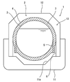
[도 2] 도 1의 일부 확대도이다.
[도 3] 변형예의 액화 가스 저류 구조를 포함하는 액화 가스 운반선의 단면도이다.
[도 4] 다른 변형예의 액화 가스 저류 구조를 포함하는 액화 가스 운반선의 단면도이다.1 is a cross-sectional view of a liquefied gas carrier including a liquefied gas storage structure according to an embodiment of the present invention.
[FIG. 2] It is a partial enlarged view of FIG.
It is sectional drawing of the liquefied gas carrier containing the liquefied gas storage structure of a modified example.
It is sectional drawing of the liquefied gas carrier containing the liquefied gas storage structure of another modified example.
도 1에 본 발명의 일 실시예에 따른 액화 가스 저류 구조를 포함하는 액화 가스 운반선(1)을 도시한다. 이러한 액화 가스 운반선(1)은 선체(11)와, 선체(11)에 탑재된 이중각 탱크(2)와, 선체(11)와 함께 이중각 탱크(2)의 주위에 유지 공간(13)을 형성하는 탱크 커버(12)를 포함한다.1 shows a
본 실시예에서는, 유지 공간(13)에 질소 가스가 충전된다. 그러나, 유지 공간(13)에는, 건조 공기가 충전되어도 좋고, 추진용 엔진의 배기 가스가 충전되어도 좋다.In this embodiment, the
이중각 탱크(2)는 액화 가스를 저류하는 내조(3)와, 내조(3)를 수용하는 외조(4)를 포함한다. 예를 들어, 액화 가스는 LNG, 액화 질소, 액화 수소, 액화 헬륨 등이다.The
내조(3)는 구형이다. 내조(3)는 반드시 구 대칭일 필요는 없고, 구 대칭에 가까운 형상이라도 좋다. 예를 들어, 내조(3)는, 구 대칭에 비해서, 내조(3)의 중심으로부터 위로 45도 각도 방향 및/또는 아래로 45도 각도 방향이 불룩한 형상이라도 좋다. 또는, 내조(3)의 상반구체와 하반구체 사이에 짧은 통형상체가 끼인 형상이라도 좋다.The
본 실시예에서는, 외조(4)도 구형이다. 외조(4)의 중심은 내조(3)의 중심과 일치하고 있다. 내조(3)와 마찬가지로 외조(4)도 반드시 구 대칭일 필요는 없고, 구 대칭에 근사하는 형상이라도 좋다. 예를 들어, 외조(4)는 내조(3)와 마찬가지로, 구 대칭에 비해서, 외조(4)의 중심으로부터 위로 45도 각도 방향 및/또는 아래로 45도 각도 방향이 불룩한 형상이라도 좋다. 또는, 외조(4)의 상반구체와 하반구체 사이에 짧은 통형상체가 끼인 형상이라도 좋다.In this embodiment, the
본 실시예에서는, 외조(4)의 재질이 내조(3)의 재질과 동일하다. 그러나, 외조(4)의 재질은 내조(3)의 재질과 달라도 좋다.In this embodiment, the material of the
내조(3)와 외조(4) 사이의 공간에는 제1 단열재(7)가 채워져 있다. 제1 단열재(7)는 외조(4)의 내측면 및 내조(3)의 외측면을 전면적으로 덮는다. 또한, 외조(4)의 외측면은 제2 단열재(8)에 의해 전면적으로 덮여 있다.A space between the
제1 단열재(7)는, 예를 들어, 폴리우레탄(PU)이나 페놀수지(PF) 등의 수지로 된 발포체라도 좋고, 펄라이트나 글라스 중공체 등의 입상체라도 좋으며, 글라스울 등의 무기 섬유라도 좋다.The first
제2 단열재(8)는, 예를 들어, 폴리우레탄이나 페놀 수지 등의 수지로 된 발포체이다. 상술한 바와 같이 유지 공간(13)에는 질소 가스가 충전되기 때문에, 제2 단열재(8)가 발포체인 경우는, 유지 공간(13)으로부터 질소 가스가 제2 단열재(8) 내에 침입하고, 제2 단열재(8) 내의 공극이 질소 가스로 충전된다. 또한, 가스 발생 장치(미도시)로부터 제2 단열재(8)에 질소 가스를 공급하여도 좋다. 여기서, 유지 공간(13)에 건조 공기가 충전되는 경우에는, 제2 단열재(8) 내의 공극에도 건조 공기가 충전되어도 좋다.The second
본 실시에에서는, 내조(3)와 외조(4) 사이의 공간에 내조(3) 내의 액화 가스가 기화한 보일오프 가스가 충전되어 있다. 그러나, 내조(3)와 외조(4) 사이의 공간에는, 내조(3) 내의 액화 가스의 온도에서는 액화되지 않는 다른 가스가 충전되어도 좋다. 또는, 내조(3)와 외조(4) 사이의 공간은 진공이라도 좋다.In this embodiment, the space between the
내조(3)와 외조(4) 사이의 공간에 보일오프 가스를 충전하는 방법으로는 다양한 방법이 채용 가능하다. 예를 들어, 내조(3)의 상부에 연통 구멍을 설치하여도 좋다. 또는, 도시는 생략하였지만, 내조(3)로부터 보일오프 가스를 다른 기기로 인도하는 이송관에 분기관을 설치하고, 이 분기관의 선단을 내조(3)와 외조(4) 사이에 개구시켜도 좋다.Various methods are employable as a method of filling the space between the
선체(11)의 바닥면(11a)과 외조(4) 사이에는 제1 지지부재(6)가 배치되어 있고, 외조(4)와 내조(3) 사이에는 제2 지지부재(5)가 배치되어 있다. 제1 지지부재(6)는 바닥면(11a)으로부터 세워져 외조(4)를 지지하고, 제2 지지부재(5)는 제1 지지부재(6)와 다른 위치에서 외조(4)의 내측면으로부터 세워져 내조(3)를 지지한다.A
본 실시예에서는, 제1 지지부재(6) 및 제2 지지부재(5)가 함께 연직 방향을 축방향으로 하는 통 형상의 스커트이다. 제1 지지부재(6)의 상단은 외조(4)의 적도부(외조(4)의 연직 중심선으로부터 가장 멀리 위치하는 최대 직경 부분)에 접합되어 있다. 마찬가지로, 제2 지지부재(5)의 상단은 내조(3)의 적도부(내조(3)의 연직 중심으로부터 가장 멀리 위치하는 최대 직경 부분)에 접합되어 있다.In the present embodiment, the first supporting
도 2에 도시된 바와 같이, 제1 지지부재(6)는, 상부(61), 중간부(62) 및 하부(63)를 포함한다. 도시된 예에서는, 상하 방향에서, 상부(61), 중간부(62) 및 하부(63)의 길이가 동일하게 되어 있지만, 그 길이는 적절하게 변경 가능하다.As shown in FIG. 2 , the
상부(61)는 외조(4)와 동일한 재질(예를 들어, 알루미늄)로 구성되고, 하부(63)는 선체(11)와 동일한 재질(예를 들어, 탄소강)로 구성된다. 중간부(62)는 외조(4) 및 선체(11) 보다 열전도율이 낮은 재질(예를 들어, 스테인레스 강)로 구성된다. 도시는 생략하였지만, 상부(61)와 중간부(62) 사이 및 중간부(62)와 하부(63)의 사이에는 이재(異材) 접합부가 설치된다. 다만, 중간부(62)는 선체(11)와 동일한 재질로 구성되어도 좋고, 외조(4)와 동일한 재질로 구성되어도 좋다.The
마찬가지로, 제2 지지부재(5)는 상부(51), 중간부(52) 및 하부(53)를 포함한다. 도시된 예에서는, 상하 방향에서, 상부(51) 및 하부(53)의 각각의 길이가 중간부(52)의 길이보다 짧게 되어 있지만, 그 길이는 적절하게 변경 가능하다.Likewise, the
상부(51)는 내조(3)와 동일한 재질(예를 들어, 알루미늄)로 구성되고, 하부(53)는 외조(4)와 동일한 재질(상술한 바와 같이, 예를 들어, 알루미늄)로 구성된다. 중간부(52)는 내조(3) 및 외조(4) 보다 열전도율이 낮은 재질(예를 들어, 스테인레스 강)로 구성된다. 도시는 생략하였지만, 상부(51)와 중간부(52) 사이 및 중간부(52)와 하부(53)의 사이에는 이재 접합부가 설치된다. 다만, 제2 지지부재(5)는 상부(51), 중간부(52) 및 하부(53)가 일체화되고, 상부(51)로부터 하부(53)까지 열전도성이 낮은 재질(예를 들어, 스테인레스 강)로 구성되어도 좋다.The
이상에서 설명한 바와 같이, 본 실시예의 액화 가스 저류 구조에서는, 바닥면(11a)으로부터 내조(3)까지의 열 침입 경로는 제1 지지부재(6), 외조(4)에서 제1 지지부재(6)와 제2 지지부재(5) 사이의 부분, 제2 지지부재(5)가 된다. 따라서, 외조(4)를 따른 제1 지지부재(6)와 제2 지지부재(5)의 이격 거리 만큼, 열 침입 경로의 길이를 확보할 수 있다. 이에 따라서, 바닥면(11a)으로부터 이중각 탱크(2) 내로의 열 침입을 저감할 수 있다.As described above, in the liquefied gas storage structure of this embodiment, the heat penetration path from the
또한, 본 실시예에서는, 제2 지지부재(5)의 상부(51) 및 하부(53)가 각각 내조(3) 및 외조(4)와 동일한 재질로 구성되어 있기 때문에, 제2 지지부재(5)를 내조(3) 및 외조(4)에 용이하게 접합할 수 있다. 나아가, 제2 지지부재(5)의 중간부(52)는 상부(51) 및 하부(53) 보다 열전도율이 낮기 때문에, 그러한 중간부(52)에 의해 제2 지지부재(5)를 통한 열전도를 억제할 수 있다.In addition, in this embodiment, since the
나아가, 본 실시예에서, 제2 지지부재(5)의 상부(51) 및 하부(53) 각각의 길이가 중간부(52)의 길이보다 짧게 되어 있기 때문에, 상부(51), 중간부(52) 및 하부(53)의 길이가 동일한 경우에 비해 이중각 탱크(2) 내로의 열 침입을 더 저감할 수 있다.Furthermore, in this embodiment, since the length of each of the
또한, 본 실시예에서는, 제1 지지부재(6)의 상부(61) 및 하부(63)가 각각 외조(4) 및 선체(11)와 동일한 재질로 구성되어 있기 때문에, 제1 지지부재(6)를 외조(4) 및 선체(11)에 용이하게 접합할 수 있다. 나아가, 제1 지지부재(6)의 중간부(62)는 상부(61) 및 하부(63) 보다 열전도율이 낮기 때문에, 그러한 중간부(62)에 의해 제1 지지부재(6)를 통한 열전도를 억제할 수 있다.In addition, in the present embodiment, since the
또한, 본 실시예에서는, 내조(3)와 외조(4) 사이의 공간에 보일오프 가스가 충전되어 있다. 내조(3)와 외조(4) 사이의 공간에 기체가 충전되어 있는 경우에는, 내조(3)에 저류되어 있는 액화 가스의 온도에 따라 내조(3)와 외조(4) 사이에서 기체가 액화 또는 고화될 가능성이 있지만, 본 실시예와 같이 그러한 기체가 보일오프 가스이면 내조(3)와 외조(4) 사이에서의 기체의 액화 또는 고화를 방지할 수 있다.In addition, in this embodiment, the space between the
(변형예)(variant example)
본 발명은 상술한 실시예에 한정되는 것이 아니고, 본 발명의 요지를 벗어나지 않는 범위에서 다양한 변형이 가능하다.The present invention is not limited to the above-described embodiments, and various modifications are possible without departing from the gist of the present invention.
예를 들어, 본 발명의 액화 가스 저류 구조는 반드시 액화 가스 운반선(1)에 포함될 필요는 없고, 육상 시설에 포함되어도 좋다. 즉, 제1 지지부재(6)가 세워진 바닥면이 지상면이라도 좋다.For example, the liquefied gas storage structure of the present invention is not necessarily included in the liquefied
또한, 내조(3)와 외조(4) 사이의 공간에는 반드시 제1 단열재(7)가 채워져 있을 필요는 없다. 예를 들어, 내조(3)와 외조(4) 사이의 공간이 진공인 경우는, 내조(3)의 외측면만이 복사 쉴드 필름과 스페이서가 교대로 적층된 적층 진공 단열재로 덮여도 좋다 .In addition, the space between the
나아가, 외조(4)의 외측면은 반드시 제2 단열재(8)로 덮여 있을 필요는 없고, 도 3에 도시된 바와 같이 노출되어 있어도 좋다. 그러나, 이 경우에는, 내조(3)로부터 외조(4)까지의 거리를 크게 하여 단열 성능을 확보할 필요가 있다. 이에 대해서, 상기 실시예와 같이 외조(4)의 외측면이 제2 단열재(8)로 덮여 있으면, 외조(4)의 외측면이 제2 단열재(8)로 덮여 있지 않은 경우에 비해, 내조(3)로부터 외조(4)까지의 거리, 다시 말해 외조(4)의 직경을 작게 할 수 있다.Furthermore, the outer surface of the
또한, 외조(4)는 반드시 구형일 필요는 없고, 예를 들어, 도 4에 도시된 바와 같은 형상이라도 좋다.In addition, the
또한, 제1 지지부재(6) 및 제2 지지부재(5)는 반드시 통 형상의 스커트일 필요는 없다. 예를 들어, 제1 지지부재(6) 및 제2 지지부재(5) 각각은 복수의 지주로 구성되어도 좋다. 이 경우, 제1 지지부재(6) 및 제2 지지부재(5)가 동일 원주 상에 위치하고, 제1 지지부재(6)를 구성하는 지주와 제2 지지부재(5)를 구성하는 지주가 둘레 방향으로 교대로 배치되어도 좋다.In addition, the
1: 액화 가스 운반선
11: 선체
11a: 바닥면
2: 이중각 탱크
3: 내조
4: 외조
5: 제2 지지부재
51: 상부
52: 중간부
53: 하부
6: 제1 지지부재
61: 상부
62: 중간부
63: 하부
7, 8: 단열재1: liquefied gas carrier
11: Hull
11a: bottom surface
2: double shell tank
3: help
4: exorcism
5: second support member
51: upper
52: middle part
53: lower
6: first support member
61: upper
62: middle part
63: lower
7, 8: insulation material
Claims (12)
바닥면으로부터 세워져 상기 외조를 지지하는 제1 지지부재와,
상기 제1 지지부재와 다른 위치에서 상기 외조의 내측면으로부터 세워져 상기 내조를 지지하는 제2 지지부재를 구비하는 것을 특징으로 하는 액화 가스 저류 구조.A double-shell tank comprising a spherical inner tank for storing liquefied gas, and an outer tank for accommodating the inner tank;
a first support member erected from the bottom to support the outer shell;
and a second support member standing up from the inner surface of the outer tank at a position different from that of the first support member and supporting the inner tank.
상기 외조는 구형이고,
상기 제2 지지부재는 상기 내조에 접합된 통 형상의 스커트이며,
상기 제1 지지부재는 상기 외조에 접합된 통 형상의 스커트인 것을 특징으로 하는 액화 가스 저류 구조.According to claim 1,
The outer shell is spherical,
The second support member is a tubular skirt joined to the inner tank,
The first support member is a liquefied gas storage structure, characterized in that the tubular skirt joined to the outer tank.
상기 제2 지지부재는 상기 내조와 동일한 재질의 상부와, 상기 외조와 동일한 재질의 하부와, 상기 내조 및 상기 외조 보다 열전도율이 낮은 재질의 중간부를 포함하는 것을 특징으로 하는 액화 가스 저류 구조.3. The method of claim 1 or 2,
The second support member includes an upper part made of the same material as the inner tank, a lower part made of the same material as the outer tank, and a middle part made of a material having lower thermal conductivity than the inner tank and the outer tank.
상기 내조 및 상기 제2 지지부재의 상부의 재질과, 상기 외조 및 상기 제2 지지부재의 하부의 재질은 동일한 것을 특징으로 하는 액화 가스 저류 구조.4. The method of claim 3,
A liquefied gas storage structure, characterized in that the material of the upper portion of the inner tank and the second support member and the material of the lower portion of the outer tank and the second support member are the same.
상하 방향에서, 상기 제2 지지부재의 상기 상부 및 상기 하부 각각의 길이는 상기 중간부의 길이 보다 짧은 것을 특징으로 하는 액화 가스 저류 구조.5. The method of claim 3 or 4,
In the vertical direction, the length of each of the upper portion and the lower portion of the second support member is a liquefied gas storage structure, characterized in that shorter than the length of the middle portion.
상기 바닥면은 선체의 바닥면이고,
상기 제1 지지부재는 상기 외조와 동일한 재질의 상부와, 상기 선체와 동일한 재질의 하부와, 상기 외조 및 상기 선체 보다 열전도율이 낮은 재질의 중간부를 포함하는 것을 특징으로 하는 액화 가스 저류 구조.6. The method according to any one of claims 1 to 5,
The bottom surface is the bottom surface of the hull,
The first support member is a liquefied gas storage structure, characterized in that it comprises an upper portion made of the same material as the outer shell, a lower portion of the same material as the hull, and a middle portion made of a material having a lower thermal conductivity than the outer shell and the hull.
상기 내조와 상기 외조 사이의 공간에는 상기 액화 가스가 기화한 보일오프 가스가 충전된 것을 특징으로 하는 액화 가스 저류 구조.7. The method according to any one of claims 1 to 6,
A liquefied gas storage structure, characterized in that the space between the inner tank and the outer tank is filled with a boil-off gas in which the liquefied gas is vaporized.
상기 내조와 상기 외조 사이의 공간에 채워져, 상기 내조의 외측면과 상기 외조의 내측면을 덮는 단열재를 더 구비하는 것을 특징으로 하는 액화 가스 저류 구조.8. The method according to any one of claims 1 to 7,
The liquefied gas storage structure, characterized in that it is filled in the space between the inner tank and the outer tank, further comprising a heat insulating material for covering the outer surface of the inner tank and the inner surface of the outer tank.
상기 외조의 외측면을 덮는 단열재를 더 구비하는 것을 특징으로 하는 액화 가스 저류 구조.9. The method according to any one of claims 1 to 8,
Liquefied gas storage structure, characterized in that it further comprises a heat insulating material covering the outer surface of the outer tank.
액화 가스를 저류하는 구형의 내조, 및 상기 내조를 수용하는 외조를 포함하는 이중각 탱크와,
상기 선체의 바닥면으로부터 세워져 상기 외조를 지지하는 제1 지지부재와,
상기 제1 지지부재와 다른 위치에서 상기 외조의 내측면으로부터 세워져 상기 내조를 지지하는 제2 지지부재를 구비하는 것을 특징으로 하는 액화 가스 운반선.hull and
A double-shell tank comprising a spherical inner tank for storing liquefied gas, and an outer tank for accommodating the inner tank;
A first support member erected from the bottom surface of the hull to support the outer shell;
and a second support member standing up from the inner surface of the outer tank at a position different from the first support member and supporting the inner tank.
상기 외조의 내측면으로부터 세워져 상기 내조를 지지하는 지지부재를 구비하고,
상기 지지부재는 상기 내조와 동일한 재질의 상부와, 상기 외조와 동일한 재질의 하부와, 상기 내조 및 상기 외조 보다 열전도율이 낮은 재질의 중간부를 포함하는 것을 특징으로 하는 액화 가스 저류 구조.A double-shell tank comprising a spherical inner tank for storing liquefied gas, and an outer tank for accommodating the inner tank;
and a support member erected from the inner surface of the outer tank to support the inner tank,
The support member includes an upper part made of the same material as the inner tank, a lower part made of the same material as the outer tank, and a middle part made of a material having lower thermal conductivity than the inner tank and the outer tank.
상기 내조 및 상기 지지부재의 상부의 재질과, 상기 외조 및 상기 지지부재의 하부의 재질은 동일한 것을 특징으로 하는 액화 가스 저류 구조.12. The method of claim 11,
A liquefied gas storage structure, characterized in that the material of the upper portion of the inner tank and the support member and the material of the lower portion of the outer tank and the support member are the same.
Applications Claiming Priority (1)
| Application Number | Priority Date | Filing Date | Title |
|---|---|---|---|
| PCT/JP2019/015226 WO2020202577A1 (en) | 2019-04-05 | 2019-04-05 | Liquefied gas storage structure and liquefied gas carrier |
Publications (1)
| Publication Number | Publication Date |
|---|---|
| KR20210141618A true KR20210141618A (en) | 2021-11-23 |
Family
ID=72666473
Family Applications (1)
| Application Number | Title | Priority Date | Filing Date |
|---|---|---|---|
| KR1020217033718A KR20210141618A (en) | 2019-04-05 | 2019-04-05 | Liquefied gas storage structure and liquefied gas carrier |
Country Status (5)
| Country | Link |
|---|---|
| EP (1) | EP3951244A4 (en) |
| JP (1) | JPWO2020202577A1 (en) |
| KR (1) | KR20210141618A (en) |
| CN (1) | CN113825942B (en) |
| WO (1) | WO2020202577A1 (en) |
Families Citing this family (3)
| Publication number | Priority date | Publication date | Assignee | Title |
|---|---|---|---|---|
| JP2023140782A (en) * | 2022-03-23 | 2023-10-05 | 川崎重工業株式会社 | Cooling down method of liquefied gas storage tank |
| WO2024062624A1 (en) * | 2022-09-22 | 2024-03-28 | 川崎重工業株式会社 | Multiple-wall tank and vessel |
| WO2024062621A1 (en) * | 2022-09-22 | 2024-03-28 | 川崎重工業株式会社 | Multi-layer tank and marine vessel |
Citations (1)
| Publication number | Priority date | Publication date | Assignee | Title |
|---|---|---|---|---|
| JP2019501064A (en) | 2015-12-22 | 2019-01-17 | シエル・インターナシヨネイル・リサーチ・マーチヤツピイ・ベー・ウイShell Internationale Research Maatschappij Besloten Vennootshap | Ship containment system for liquefied gas |
Family Cites Families (14)
| Publication number | Priority date | Publication date | Assignee | Title |
|---|---|---|---|---|
| JPS5653198Y2 (en) * | 1973-09-21 | 1981-12-11 | ||
| NO743932L (en) * | 1974-10-31 | 1976-05-03 | Moss Rosenberg Verft As | |
| JPS6030880B2 (en) * | 1977-12-28 | 1985-07-18 | 川崎重工業株式会社 | Spherical tank support structure |
| JPS55112198U (en) * | 1979-01-31 | 1980-08-07 | ||
| JPH0214720Y2 (en) * | 1985-01-10 | 1990-04-20 | ||
| JPH01102600U (en) * | 1987-12-28 | 1989-07-11 | ||
| JPH1182889A (en) * | 1997-09-10 | 1999-03-26 | I H I Plantec:Kk | Vertical type heat insulating low temperature tank |
| JP4431842B2 (en) * | 1998-03-31 | 2010-03-17 | 株式会社石井鐵工所 | Inner tank support structure of double shell spherical storage tank |
| CN101280879A (en) * | 2008-05-16 | 2008-10-08 | 北京冠天能工程科技有限公司 | Supporting device of spherical storage tank and spherical storage tank with the same |
| CN101737623A (en) * | 2008-11-17 | 2010-06-16 | 张家港韩中深冷科技有限公司 | Supporting device of inner container in low-temperature storage tank |
| WO2014132661A1 (en) * | 2013-03-01 | 2014-09-04 | パナソニック株式会社 | Insulating container |
| WO2014203530A1 (en) * | 2013-06-21 | 2014-12-24 | 川崎重工業株式会社 | Liquefied gas-storing tank and liquefied gas transport vessel |
| JP6535928B2 (en) * | 2016-05-16 | 2019-07-03 | 三菱造船株式会社 | Liquefied gas quenchability determination device, liquefied gas storage tank, liquefied gas carrier, and quenchability determination method by liquefied gas |
| CN206545778U (en) * | 2016-12-06 | 2017-10-10 | 成都深冷科技有限公司 | A kind of three wall metal atmospheric storage tanks stored for LNG |
-
2019
- 2019-04-05 EP EP19922629.1A patent/EP3951244A4/en active Pending
- 2019-04-05 WO PCT/JP2019/015226 patent/WO2020202577A1/en unknown
- 2019-04-05 KR KR1020217033718A patent/KR20210141618A/en not_active Application Discontinuation
- 2019-04-05 JP JP2021511073A patent/JPWO2020202577A1/ja active Pending
- 2019-04-05 CN CN201980094617.5A patent/CN113825942B/en active Active
Patent Citations (1)
| Publication number | Priority date | Publication date | Assignee | Title |
|---|---|---|---|---|
| JP2019501064A (en) | 2015-12-22 | 2019-01-17 | シエル・インターナシヨネイル・リサーチ・マーチヤツピイ・ベー・ウイShell Internationale Research Maatschappij Besloten Vennootshap | Ship containment system for liquefied gas |
Also Published As
| Publication number | Publication date |
|---|---|
| CN113825942A (en) | 2021-12-21 |
| JPWO2020202577A1 (en) | 2020-10-08 |
| EP3951244A1 (en) | 2022-02-09 |
| EP3951244A4 (en) | 2022-12-07 |
| WO2020202577A1 (en) | 2020-10-08 |
| CN113825942B (en) | 2024-02-02 |
Similar Documents
| Publication | Publication Date | Title |
|---|---|---|
| KR102662477B1 (en) | Liquefied gas tank and liquefied gas carrier | |
| KR101871324B1 (en) | Double-shelled tank and liquefied gas transport vessel | |
| KR20210141618A (en) | Liquefied gas storage structure and liquefied gas carrier | |
| JP6220164B2 (en) | Double shell tank and liquefied gas carrier | |
| US20140166662A1 (en) | Suspension System for a Cryogenic Vessel | |
| KR20210141627A (en) | Double shell tanks and liquefied gas carriers | |
| JP2021515151A (en) | Container for storing and transporting liquefied gas | |
| JPH08295394A (en) | Cryostatic tank for cryogenic liquefied gas | |
| US6453680B1 (en) | Liquid helium transport container with longitudinally-mounted external liquid nitrogen coolant tanks | |
| US7448511B2 (en) | Double-wall tank | |
| KR101643083B1 (en) | Low heat loss cryogenic fluid storage equipment using multilayered cylindrical support | |
| KR20200060506A (en) | Double shell tank and ship | |
| KR101616352B1 (en) | Liquefied Gas Storage Tank | |
| JP2022186098A (en) | Multiple shell tank | |
| EP4230902A1 (en) | Double-walled heat insulation piping unit for liquefied gas, and liquefied gas storage vessel comprising same | |
| JP2021514327A (en) | System for storing and transporting cold fluids on ships | |
| KR102340889B1 (en) | Double shell tanks and liquefied gas carriers | |
| KR20230024370A (en) | double angle tank | |
| JP7261007B2 (en) | double shell tank | |
| KR102651094B1 (en) | Pump Tower Lower Support | |
| WO2023157262A1 (en) | Floating structure, displacement amount acquisition method, and supporting state determination method | |
| KR20230167774A (en) | Insulation structure of cargo tank | |
| KR20240018001A (en) | Storage tank having double insulation structure | |
| KR20230021749A (en) | Double angle tanks and vessels | |
| JP2022103917A (en) | Triple shell tank |
Legal Events
| Date | Code | Title | Description |
|---|---|---|---|
| E902 | Notification of reason for refusal | ||
| E601 | Decision to refuse application | ||
| J201 | Request for trial against refusal decision | ||
| J301 | Trial decision |
Free format text: TRIAL NUMBER: 2023101002698; TRIAL DECISION FOR APPEAL AGAINST DECISION TO DECLINE REFUSAL REQUESTED 20231215 Effective date: 20240228 |