KR20210129044A - Systems and methods for perturbing permanent magnet asymmetric magnetic fields - Google Patents
Systems and methods for perturbing permanent magnet asymmetric magnetic fields Download PDFInfo
- Publication number
- KR20210129044A KR20210129044A KR1020217024871A KR20217024871A KR20210129044A KR 20210129044 A KR20210129044 A KR 20210129044A KR 1020217024871 A KR1020217024871 A KR 1020217024871A KR 20217024871 A KR20217024871 A KR 20217024871A KR 20210129044 A KR20210129044 A KR 20210129044A
- Authority
- KR
- South Korea
- Prior art keywords
- magnetic field
- perturbation
- permanent magnet
- rotating body
- axis
- Prior art date
Links
Images


Classifications
-
- H—ELECTRICITY
- H01—ELECTRIC ELEMENTS
- H01F—MAGNETS; INDUCTANCES; TRANSFORMERS; SELECTION OF MATERIALS FOR THEIR MAGNETIC PROPERTIES
- H01F7/00—Magnets
- H01F7/02—Permanent magnets [PM]
- H01F7/0205—Magnetic circuits with PM in general
-
- H—ELECTRICITY
- H02—GENERATION; CONVERSION OR DISTRIBUTION OF ELECTRIC POWER
- H02K—DYNAMO-ELECTRIC MACHINES
- H02K7/00—Arrangements for handling mechanical energy structurally associated with dynamo-electric machines, e.g. structural association with mechanical driving motors or auxiliary dynamo-electric machines
- H02K7/02—Additional mass for increasing inertia, e.g. flywheels
- H02K7/025—Additional mass for increasing inertia, e.g. flywheels for power storage
-
- F—MECHANICAL ENGINEERING; LIGHTING; HEATING; WEAPONS; BLASTING
- F03—MACHINES OR ENGINES FOR LIQUIDS; WIND, SPRING, OR WEIGHT MOTORS; PRODUCING MECHANICAL POWER OR A REACTIVE PROPULSIVE THRUST, NOT OTHERWISE PROVIDED FOR
- F03G—SPRING, WEIGHT, INERTIA OR LIKE MOTORS; MECHANICAL-POWER PRODUCING DEVICES OR MECHANISMS, NOT OTHERWISE PROVIDED FOR OR USING ENERGY SOURCES NOT OTHERWISE PROVIDED FOR
- F03G3/00—Other motors, e.g. gravity or inertia motors
- F03G3/08—Other motors, e.g. gravity or inertia motors using flywheels
-
- H—ELECTRICITY
- H01—ELECTRIC ELEMENTS
- H01F—MAGNETS; INDUCTANCES; TRANSFORMERS; SELECTION OF MATERIALS FOR THEIR MAGNETIC PROPERTIES
- H01F1/00—Magnets or magnetic bodies characterised by the magnetic materials therefor; Selection of materials for their magnetic properties
-
- H—ELECTRICITY
- H01—ELECTRIC ELEMENTS
- H01F—MAGNETS; INDUCTANCES; TRANSFORMERS; SELECTION OF MATERIALS FOR THEIR MAGNETIC PROPERTIES
- H01F1/00—Magnets or magnetic bodies characterised by the magnetic materials therefor; Selection of materials for their magnetic properties
- H01F1/0036—Magnets or magnetic bodies characterised by the magnetic materials therefor; Selection of materials for their magnetic properties showing low dimensional magnetism, i.e. spin rearrangements due to a restriction of dimensions, e.g. showing giant magnetoresistivity
-
- H—ELECTRICITY
- H01—ELECTRIC ELEMENTS
- H01F—MAGNETS; INDUCTANCES; TRANSFORMERS; SELECTION OF MATERIALS FOR THEIR MAGNETIC PROPERTIES
- H01F1/00—Magnets or magnetic bodies characterised by the magnetic materials therefor; Selection of materials for their magnetic properties
- H01F1/01—Magnets or magnetic bodies characterised by the magnetic materials therefor; Selection of materials for their magnetic properties of inorganic materials
- H01F1/03—Magnets or magnetic bodies characterised by the magnetic materials therefor; Selection of materials for their magnetic properties of inorganic materials characterised by their coercivity
- H01F1/032—Magnets or magnetic bodies characterised by the magnetic materials therefor; Selection of materials for their magnetic properties of inorganic materials characterised by their coercivity of hard-magnetic materials
- H01F1/04—Magnets or magnetic bodies characterised by the magnetic materials therefor; Selection of materials for their magnetic properties of inorganic materials characterised by their coercivity of hard-magnetic materials metals or alloys
- H01F1/06—Magnets or magnetic bodies characterised by the magnetic materials therefor; Selection of materials for their magnetic properties of inorganic materials characterised by their coercivity of hard-magnetic materials metals or alloys in the form of particles, e.g. powder
-
- H—ELECTRICITY
- H01—ELECTRIC ELEMENTS
- H01F—MAGNETS; INDUCTANCES; TRANSFORMERS; SELECTION OF MATERIALS FOR THEIR MAGNETIC PROPERTIES
- H01F7/00—Magnets
- H01F7/02—Permanent magnets [PM]
- H01F7/0231—Magnetic circuits with PM for power or force generation
- H01F7/0242—Magnetic drives, magnetic coupling devices
-
- H—ELECTRICITY
- H02—GENERATION; CONVERSION OR DISTRIBUTION OF ELECTRIC POWER
- H02K—DYNAMO-ELECTRIC MACHINES
- H02K1/00—Details of the magnetic circuit
- H02K1/02—Details of the magnetic circuit characterised by the magnetic material
-
- H—ELECTRICITY
- H02—GENERATION; CONVERSION OR DISTRIBUTION OF ELECTRIC POWER
- H02K—DYNAMO-ELECTRIC MACHINES
- H02K1/00—Details of the magnetic circuit
- H02K1/06—Details of the magnetic circuit characterised by the shape, form or construction
- H02K1/22—Rotating parts of the magnetic circuit
- H02K1/27—Rotor cores with permanent magnets
- H02K1/2706—Inner rotors
- H02K1/272—Inner rotors the magnetisation axis of the magnets being perpendicular to the rotor axis
- H02K1/274—Inner rotors the magnetisation axis of the magnets being perpendicular to the rotor axis the rotor consisting of two or more circumferentially positioned magnets
-
- H—ELECTRICITY
- H02—GENERATION; CONVERSION OR DISTRIBUTION OF ELECTRIC POWER
- H02K—DYNAMO-ELECTRIC MACHINES
- H02K1/00—Details of the magnetic circuit
- H02K1/06—Details of the magnetic circuit characterised by the shape, form or construction
- H02K1/22—Rotating parts of the magnetic circuit
- H02K1/27—Rotor cores with permanent magnets
- H02K1/2786—Outer rotors
- H02K1/2787—Outer rotors the magnetisation axis of the magnets being perpendicular to the rotor axis
- H02K1/2789—Outer rotors the magnetisation axis of the magnets being perpendicular to the rotor axis the rotor consisting of two or more circumferentially positioned magnets
- H02K1/2791—Surface mounted magnets; Inset magnets
-
- H—ELECTRICITY
- H02—GENERATION; CONVERSION OR DISTRIBUTION OF ELECTRIC POWER
- H02K—DYNAMO-ELECTRIC MACHINES
- H02K1/00—Details of the magnetic circuit
- H02K1/06—Details of the magnetic circuit characterised by the shape, form or construction
- H02K1/22—Rotating parts of the magnetic circuit
- H02K1/27—Rotor cores with permanent magnets
- H02K1/2793—Rotors axially facing stators
- H02K1/2795—Rotors axially facing stators the rotor consisting of two or more circumferentially positioned magnets
- H02K1/2796—Rotors axially facing stators the rotor consisting of two or more circumferentially positioned magnets where both axial sides of the rotor face a stator
-
- H—ELECTRICITY
- H02—GENERATION; CONVERSION OR DISTRIBUTION OF ELECTRIC POWER
- H02K—DYNAMO-ELECTRIC MACHINES
- H02K7/00—Arrangements for handling mechanical energy structurally associated with dynamo-electric machines, e.g. structural association with mechanical driving motors or auxiliary dynamo-electric machines
- H02K7/02—Additional mass for increasing inertia, e.g. flywheels
-
- H—ELECTRICITY
- H02—GENERATION; CONVERSION OR DISTRIBUTION OF ELECTRIC POWER
- H02K—DYNAMO-ELECTRIC MACHINES
- H02K2211/00—Specific aspects not provided for in the other groups of this subclass relating to measuring or protective devices or electric components
- H02K2211/03—Machines characterised by circuit boards, e.g. pcb
-
- Y—GENERAL TAGGING OF NEW TECHNOLOGICAL DEVELOPMENTS; GENERAL TAGGING OF CROSS-SECTIONAL TECHNOLOGIES SPANNING OVER SEVERAL SECTIONS OF THE IPC; TECHNICAL SUBJECTS COVERED BY FORMER USPC CROSS-REFERENCE ART COLLECTIONS [XRACs] AND DIGESTS
- Y02—TECHNOLOGIES OR APPLICATIONS FOR MITIGATION OR ADAPTATION AGAINST CLIMATE CHANGE
- Y02E—REDUCTION OF GREENHOUSE GAS [GHG] EMISSIONS, RELATED TO ENERGY GENERATION, TRANSMISSION OR DISTRIBUTION
- Y02E60/00—Enabling technologies; Technologies with a potential or indirect contribution to GHG emissions mitigation
- Y02E60/16—Mechanical energy storage, e.g. flywheels or pressurised fluids
Abstract
몸체를 이동시키기 위해 영구 자석 비대칭 자기장을 교란시키는 시스템 및 방법은 회전 축을 중심으로 회전하도록 구성된 회전체, 2개 이상의 영구 자석들을 포함하는 회전체 상에 배열된 영구 자석 어레인지먼트, 및 교란 요소를 포함한다. 영구 자석 어레인지먼트는 섭동 지점에 대해 영구 자석에 의해 비대칭 자기장이 생성되도록 구성된다. 섭동 지점 또는 그 근처에서 섭동 요소의 작동은 회전체 및/또는 영구 자석 어레인지먼트에 접선 자기력을 발생시켜 회전체가 회전 축을 중심으로 회전하게 한다. 개시는 또한 몸체의 선형 운동에 사용될 수 있다. A system and method for perturbing a permanent magnet asymmetric magnetic field to move a body includes a rotating body configured to rotate about an axis of rotation, a permanent magnet arrangement arranged on the rotating body comprising two or more permanent magnets, and a disturbance element . The permanent magnet arrangement is configured such that an asymmetric magnetic field is created by the permanent magnet with respect to the point of perturbation. Actuation of the perturbating element at or near the perturbation point generates a tangential magnetic force in the rotating body and/or the permanent magnet arrangement causing the rotating body to rotate about its axis of rotation. Initiation can also be used for linear motion of the body.
Description
본 출원은 2019년 1월 9일자로 출원된 미국 가특허출원 제62/917,940호의 이익을 주장하며, 이 가출원은 해당 법률에 따라 허용되는 최대한의 범위 내에서 그 전체가 참고로 여기에 포함된다. This application claims the benefit of U.S. Provisional Patent Application No. 62/917,940, filed January 9, 2019, which is hereby incorporated by reference in its entirety to the fullest extent permitted by applicable law.
회전 기계 운동을 포함하여 몸체의 기계 운동을 일으키는 시스템 및 방법이 알려져 있다. 전기 모터들과 같은, 기계적 에너지 또는 일 또는 운동을 생성하기 위한 종래의 시스템 및 방법이 알려져 있다. 그러나, 그러한 시스템은 실행에 상당한 전력을 사용하고 종종 비효율적이다. 따라서, 위에서 논의된 선행 기술의 단점을 극복하고 기존 시스템보다 적은 에너지를 사용하여 작업 또는 동작을 매우 효율적으로 제공하는 시스템 및 방법을 설계하는 것이 바람직할 것이다. Systems and methods for causing mechanical motion of a body, including rotational mechanical motion, are known. Conventional systems and methods for generating mechanical energy or work or motion, such as electric motors, are known. However, such systems use significant power to run and are often inefficient. Accordingly, it would be desirable to design a system and method that overcomes the disadvantages of the prior art discussed above and provides a task or operation very efficiently using less energy than existing systems.
(본문에 포함되어 있음)(Included in the text)
도 1은 현재 개시의 실시예에 따른 영구 자석 비대칭 자기장 시스템의 평면도 및 측면도이다.
도 2는 현재 개시의 실시예들에 따른 도 1의 영구 자석 비대칭 자기장 시스템의 평면도이다.
도 3은 현재 개시의 실시예들에 따른 영구 자석 비대칭 자기장 시스템의 평면도이다.
도 4는 현재 개시의 실시예들에 따른 영구 자석 비대칭 자기장 시스템의 평면도이다.
도 5는 현재 개시의 실시예에 따른 영구 자석 비대칭 자기장 시스템의 측면도이다.
도 6은 현재 개시의 실시예들에 따른 도 5의 영구 자석 비대칭 자기장 시스템의 평면도이다.
도 7은 현재 개시의 실시예에 따른 영구 자석 비대칭 자기장 시스템의 측면도이다.
도 8은 현재 개시의 실시예에 따른 영구 자석 비대칭 자기장 시스템의 측면도이다.
도 9는 현재 개시의 실시예들에 따른 도 8의 영구 자석 비대칭 자기장 시스템의 평면도이다.
도 10은 현재 개시의 실시예들에 따른 영구 자석 비대칭 자기장 시스템의 사시도이다.
도 11은 현재 개시의 실시예들에 따른 도 10의 영구 자석 비대칭 자기장 시스템의 평면도이다.
도 12는 현재 개시의 실시예들에 따른 영구 자석 비대칭 자기장 시스템의 측면도이다.
도 13은 현재 개시의 실시예에 따른 영구 자석 비대칭 자기장 시스템의 평면도이다. 1 is a top and side view of a permanent magnet asymmetric magnetic field system in accordance with an embodiment of the present disclosure;
2 is a plan view of the permanent magnet asymmetric magnetic field system of FIG. 1 in accordance with embodiments of the present disclosure;
3 is a plan view of a permanent magnet asymmetric magnetic field system in accordance with embodiments of the present disclosure;
4 is a plan view of a permanent magnet asymmetric magnetic field system in accordance with embodiments of the present disclosure;
5 is a side view of a permanent magnet asymmetric magnetic field system according to an embodiment of the present disclosure;
6 is a top view of the permanent magnet asymmetric magnetic field system of FIG. 5 in accordance with embodiments of the present disclosure;
7 is a side view of a permanent magnet asymmetric magnetic field system according to an embodiment of the present disclosure;
8 is a side view of a permanent magnet asymmetric magnetic field system in accordance with an embodiment of the present disclosure;
9 is a top view of the permanent magnet asymmetric magnetic field system of FIG. 8 in accordance with embodiments of the present disclosure;
10 is a perspective view of a permanent magnet asymmetric magnetic field system in accordance with embodiments of the present disclosure;
11 is a top view of the permanent magnet asymmetric magnetic field system of FIG. 10 in accordance with embodiments of the present disclosure;
12 is a side view of a permanent magnet asymmetric magnetic field system in accordance with embodiments of the present disclosure;
13 is a plan view of a permanent magnet asymmetric magnetic field system according to an embodiment of the present disclosure;
아래에서 더 상세히 논의되는 바와 같이, 일부 실시예에서, 현재 개시는 몸체의 운동을 제공하기 위해 영구 자석 비대칭 자기장을 교란시키기 위한 시스템 및 방법에 관한 것이다. 현재 개시의 시스템 및 방법은 원하는 설계 매개변수에 기초하여 임의의 형상 및 크기의 영구 자석을 사용할 수 있고 하우징과 함께 또는 하우징 없이 구성될 수 있다. 현재 개시내용은 자기(또는 자속) 회로 구성에 기초하여 자기장에 저장된 위치 에너지를 갖는 비대칭 자기장을 초래하는 영구 자석 어레인지먼트를 갖는다. As discussed in more detail below, in some embodiments, the present disclosure relates to systems and methods for perturbing a permanent magnet asymmetric magnetic field to provide motion of a body. The systems and methods of the present disclosure can use permanent magnets of any shape and size based on desired design parameters and can be configured with or without a housing. The present disclosure has a permanent magnet arrangement that results in an asymmetric magnetic field with potential energy stored in the magnetic field based on a magnetic (or magnetic flux) circuit configuration.
비대칭 자기장을 섭동시키는 섭동 요소에 의해 적용된 작은 입력 힘은 적용된 입력 힘(또는 힘 증폭)보다 큰 출력 힘을 초래하는 영구 자석 구성에 의해 잠재적 에너지의 방출을 유발하여, 영구 자석 구동(또는 보조) 힘 증폭기를 제공한다는 것을 발견하였다. The small input force applied by the perturbing element perturbing the asymmetric magnetic field causes the release of potential energy by the permanent magnet construction resulting in an output force greater than the applied input force (or force amplification), resulting in a permanent magnet driving (or auxiliary) force. It has been found to provide an amplifier.
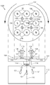
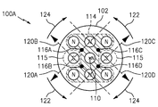
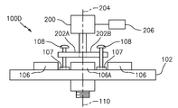
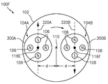
도 1 및 2를 참조하면, 영구 자석 비대칭 자기장 시스템(100A)의 예시적인 실시예가 현재 개시의 실시예들에 따라 도시된다. 시스템(100A)은(플라이휠과 같은) 회전체(102), 복수의 영구 자석(106)을 갖는 영구 자석 어레인지먼트(104), 및 섭동 요소(또는 제어 막대 또는 드라이버 핀)(108)를 포함한다. 회전체(102)는 회전 축(110)을 중심으로 회전하도록 구성된다. 회전 몸체(102)는 볼트(123) 등에 의해 몸체(102)에 부착될 수 있는 샤프트(125)에 의해 교류 발전기/발전기(112)에 연결된 것으로 도시되어 있다. 또한, 교류 발전기/발전기(112)는 과열을 피하기 위해 통기 구멍(12)들을 가질 수 있다. 1 and 2 , an exemplary embodiment of a permanent magnet asymmetric
이 실시예에서, 섭동 요소(108)는 철계 재료로 만들어진 철계 몸체를 구성하는 강철 나사 또는 못 또는 막대 또는 핀이다. 이 실시예는 섭동 요소(108)의 팁을 위한 소켓 형태의 선택적 레스트들(또는 시트들)(107)와 함께 도시되어 있다. 레스트(107)들은 플라스틱 및/또는 금속, 또는 임의의 다른 재료로 형성될 수 있거나, 일부 실시예에서 하단 플레이트(102)의 디봇(divot)들 또는 만입부(indentation)들일 수 있다. In this embodiment, the
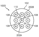
어레인지먼트(104)의 영구 자석(106)들은 하나 이상의 섭동 지점(116A, 116B, 116C, 116D)(집합적으로 "116") 주위에 결과적인 메이저 자기장(114)(또는 메이저 장(114)) 및 마이너 자기장(115)(또는 마이너 자기장(115))과 함께 비대칭 자기장이 생성되도록 회전체(102) 상에 고정적으로 배열된다. 각각의 섭동 지점(116)은 섭동 지점(116)을 원주방향으로 둘러싸는 4개의 자석(106)의 클러스터를 가지며, 각 자석(106)은 섭동 지점(116)으로부터 동일한 반경 방향 거리 또는 실질적으로 동일한 거리를 갖는다. 일부 클러스터는 하나 이상의 공통 자석(106)들을 공유한다. 자석(106)들의 각 클러스터들에는, 메이저 자기장을 생성하는 회전체(102)로부터 멀어지는 방향을 향하는 동일한 북쪽(N) 극성을 갖는 상부 표면을 갖는 3개의 자석(106) 및 마이너 자기장(115)을 생성하는 회전체(102)로부터 멀어지는 남쪽(S) 극성을 갖는 상부 표면을 갖는 하나의 자석(106)이 있다. 각각의 섭동 지점(116)은 회전 축(110)에 실질적으로 평행한 섭동 축(118)을 갖는다. 또한, 몸체(102)가 회전하는 구성의 중앙에 위치하는 공통 자석(106A)이 있다. The
몸체(102)(또는 하단 플레이트)가 강철인 경우 자석(1067)은 몸체(102)에 자기적으로 고정되거나 부착될 수 있으며; 그렇지 않으면, 자석(106)은 볼트, 접착제, 클레임 또는 다른 부착 수단에 의해 몸체에 고정될 수 있다. 원하는 경우 몸체에 내장될 수도 있다. Magnet 1067 may be magnetically fixed or attached to
현재 출원의 목적을 위해, 비대칭 자기장은 "메이저" 자기장 및 "마이너" 자기장을 포함하고, 메이저 자기장(114)은 마이너 자기장(115)보다 크기가 더 크고 및/또는 메이저 자기장(114)는 마이너 자기장(115)보다 큰 자기장 강도를 갖는다. 이 실시예에서, 자석은 동일 평면 매트릭스 패턴을 형성하여 주요 자기장(114)의 H-패턴 자속 라인을 형성한다. 이 실시예는 마이너 자기장(115)을 생성하기 위한 자석(106)의 수보다 메이저 자기장(114)을 생성하기 위한 자석(106)의 수가 더 많다는 것을 보여주지만, 마이너 자기장(115)을 생성하기 위한 다수의 자석(106)이 존재하는 것은 현재 개시의 범위 내에 있다. 예를 들어, 메이저(114) 자기장을 생성하는 자석(106)은 마이너 자기장을 생성하는 더 많은 수의 "약한" 자석(106)보다 더 적지만 "더 강"할 수 있다. 어느 하나의 자기장(114, 115)들에 대한 자석(106)은 동일한 모양, 크기 또는 강도일 필요가 없으며, 하나 또는 두 자기장(114, 115)들 모두에 대해 다른 자석 유형/모양이 있을 수 있다. For purposes of the present application, asymmetric magnetic fields include “major” and “minor” magnetic fields, wherein the major
이 실시예에서, 플라이휠 회전체(102)는 약 15" 직경 x 1.25" 두께이고 약 80파운드이고 자동차/트럭 플라이휠이다. 그러나, 다른 크기, 형상 및 중량 회전체(102)는 현재 개시의 범위 내에 있다. 교류 발전기/발생기(112)는 266rpm에서 배터리 전압에 도달하는 미주리 풍력 및 솔라에서 제조한 48볼트 영구 자석 발전기 모델 FREEDOM PMG이다. 그러나, 다른 유형의 교류 발전기/발생기가 현재 개시의 범위 내에 있다. In this embodiment, the
다양한 하우징 및 자석 구성이 현재 개시내용의 범위 내에 있다. 예를 들어, 제한없이, 영구 자석(106)들을 둘러싸는 하우징은 하단에 8" 직경 x 1/4" 두께의 철강 디스크, 상단에 8" 직경 x 1/4" 두께의 알루미늄 캡으로 덮인 8" 외경 x 7" 내경 x 2" 높이를 갖는 8" 직경 x 1/4" 두께로 덮인 밀폐형 고철강 실린더일 수 있다. 여기에 설명된 바와 같이, 캡, 하단 및 측들)은 철계 재료 또는 비철계 재료로 만들어질 수 있다. 영구 자석(106)들은 예를 들어 제한 없이 축방향으로 자화된 1-1.25" 직경 x 0.5" 두께(또는 높이) NdFe/원통형 희토류 자석일 수 있다. 영구 자석(106)들은 K&J Magnetics, 부품 번호 DX48에서 "기성품"으로 구입할 수 있다. Various housing and magnet configurations are within the scope of the present disclosure. For example, and without limitation, the housing enclosing the
작동 중에, 섭동 요소(108)가 초기 위치에서 섭동 지점(116)(또는 섭동 지점(116) 근처)에 배치될 때, 섭동 요소(108)의 길이 방향 연장부가 섭동 축(118)에 평행하도록(또는 섭동 지점(116)에서 회전체(102)의 표면에 수직이 되도록) 되고 그 다음 제공된 입력 힘(또는 적용된 힘)을 통해 마이너 자기장의 중심점 및/또는 마이너 자기장을 생성하는 자석(들)(106)의 중심점을 향하는 방향(120A, 120B, 120C, 120D )으로 섭동 축(118)으로부터 벗어나도록 작동된다. 섭동 축(118)으로부터의 편차(119)가 도 1에 도시되어 있다. 섭동 요소(108)는 섭동 지점(116)의 실질적으로 중앙 부분에 삽입될 수 있지만, 시스템 및 방법은 섭동 요소(108)가 섭동 지점(116)의 중앙 부분으로부터 방사상 오프셋될 때 작동할 수 있다. 이 실시예에서, 마이너 자기장(115)의 중심점은 회전체(102)(또는 하단 플레이트)로부터 멀어지는 남쪽 극성(S)을 갖는 자석(106)의 중심점과 정렬된다. 이러한 방식으로 섭동 축(118)으로부터 멀어지는 섭동 요소(108)의 작동은, 비대칭 자기장(114, 115)의 왜곡(또는 섭동)을 유발하고, 회전 축(110)을 중심으로 영구 자석 어레인지먼트(104) 및/또는 회전 몸체(102)에 결과적인 접선 자기력을 생성하고, 따라서 접선 자기력이 접선 자기력에 저항하는 마찰 및/또는 하중보다 크다고 가정할 때, 회전체(102)가 반시계 방향(122) 또는 시계 방향(124)으로 회전 축(110)을 중심으로 회전하게 한다. 유리하게는, 영구 자석 어레인지먼트(104)는 반시계 방향(122) 회전 및 시계 방향(124) 회전을 허용하며, 이는 양방향성의 순방향 및 역방향 옵션으로 간주될 수 있다. During operation, when the
일부 실시예들에서, 회전체(102)의 회전은 임의의 방향으로 섭동 축(118)으로부터 벗어나도록 섭동 요소(108)의 작동에 의해 야기될 수 있다. 예를 들어, 섭동 축(118)으로부터 섭동 요소(108)의 몇 도의 워블(wobble)은 또한 회전체(102)의 회전을 야기할 것이다. In some embodiments, rotation of the
현재 개시에 따른 실시예들에서, 섭동 축(118)으로부터 벗어나도록 섭동 요소(108)를 작동시키는 데 필요한 입력 힘은 회전체(102)에 작용하는 결과적인 접선 자기력보다 작다. 이것은 회전체(102)가 제공된 입력 힘(또는 인가된 힘)보다 더 큰 회전 축(110)을 중심으로 회전하도록 구동하기 위한 접선 자기력을 생성하는 영구 자석 어레인지먼트(104)에 포함된 위치 에너지로 인해 가능하다. 따라서, 현재 개시는 영구 자기 구동식 힘 증폭기를 제공한다. In embodiments according to the present disclosure, the input force required to actuate the
회전체(102)의 회전은 예를 들어 전기 생성, 자동차 추진, 보트 또는 비행기의 프로펠러 구동 등과 같은 작업을 수행하기 위해 회전체에 적합한 임의의 애플리케이션에 사용될 수 있다. 예를 들어, 현재 개시내용에 따른 실시예는 풍력 터빈의 회전을 용이하게 하여, 특히 낮은 풍속에서 전기를 생성하기 위해 시동 시에 필요한 입력 에너지를 상당히 감소시킬 수 있다. 실시예는 수평 풍력 터빈(또는 HAWT) 또는 수직 풍력 터빈(또는 VAWT)에서 회전을 용이하게 할 수 있다. 현재 개시에 따른 실시예는 플라이휠 및 풍력 터빈의 발전기 또는 발생기와 결합될 수 있다. 현재 개시에 따른 실시예들은 주거용, 상업용 및/또는 유틸리티 규모 사용 애플리케이션에서 사용될 수 있다. The rotation of the
회전체(102)는 단일 섭동 요소(108)에 의한 비대칭 자기장의 섭동에 의해 설명된 바와 같이 회전하도록 야기될 수 있다. 그러나, 임의의 수의 섭동 요소(108)들이 각각의 섭동 지점(116)들에서 작동될 수 있다. 예를 들어, 제1 섭동 요소(108)는 섭동 지점(116A)에서 작동될 수 있는 반면, 제2 섭동 요소(108)는 반시계 방향으로 회전체(102)를 구동하기 위해 섭동 지점(116D)에서 동시에(또는 실질적으로 동시에) 작동된다. 유사하게, 제3 섭동 요소(108)는 섭동 지점(116B)에서 작동될 수 있는 반면, 제4 섭동 요소(108)는 시계 방향으로 회전체(102)를 구동하기 위해 섭동 지점(116C)에서 동시에(또는 실질적으로 동시에) 작동된다. 추가 섭동 요소(108)가 대향하는 섭동 지점(116)들에서 작동되는 것으로 도시되어 있지만, 다른 실시예들에서 추가 섭동 요소(108)는 회전 축을 중심으로 대향하는 섭동 지점(116)들에 있지 않는다. 예를 들어, 섭동 요소(108)는 30º, 45 º 또는 90 º 각도 분리에서 섭동 지점(116)에 있을 수 있다. 그러나, 임의의 다른 각도 분리도는 현재 개시의 범위 내에 있다. 자석(106)의 수 및 영구 자석 어레인지먼트의 형상/구성에 따라, 임의의 수의 섭동 요소(108) 및/또는 섭동 지점(116)이 있을 수 있다. 추가 섭동 요소(108)들 및 섭동 지점(116)들은 자석(106)의 강도에 따라 회전체(102)에 추가 접선 자기력을 제공하는 능력을 제공한다. The
도 1 및 도 2의 실시예에서 도시되고 설명된 자석(106)들은 원통형 자석이다. 그러나, 자석의 임의의 유형 또는 형상은 현재 개시내용의 범위 내에 있다. 예를 들어, 자석(106)은 직사각형 막대 자석, 원형 평면(또는 디스크) 자석 등일 수 있다. The
섭동 요소(108)들이 강철 나사인 것으로 도시되고 설명되었지만, 섭동 요소(108)가 사실상 임의의 크기 및 형상이고, 예를 들어 강철, 강철 합금, 철, 철 합금 등과 같은 임의의 철 재료로 제조되는 것은 현재 개시의 범위 내에 있다. 섭동 요소(108)는 또한 예를 들어 원추형 자석, 원통형 자석 등과 같은 영구 자석일 수 있다. 자석 형태의 섭동 요소(108)는 유사한 질량, 크기 및/또는 모양의 철계 몸체 섭동 요소(108)보다 비대칭 자기장의 더 큰 왜곡 또는 섭동을 제공함으로써 입력 힘(또는 적용된 힘)의 더 큰 증폭을 제공할 수 있다. 섭동 요소(108)의 질량, 크기 및 형상은 섭동 요소(108)의 원하는 자기장 섭동 특성들, 예를 들어 섭동 요소(108)의 작동(119)의 각도 또는 거리당 접선 자기력의 양을 조정하거나 강도를 달성하기 위해 원하는 대로 조정될 수 있다. 일부 실시예들에서, 작은 자기장(115)를 생성하는 회전체(102)로부터 멀어지는 방향을 향하는 자석(106)의 측면의 극성이 섭동 요소(108)의 상부 또는 원위 단부 배열되어, 동일한 극성의 철계 제어 로드에 바이어스 자석을 배치함으로써 입력 힘의 더 큰 증폭이 달성될 수 있다. Although
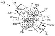
도 3을 참조하면, 두 개의 자석(106)들이 제거된 것을 제외하고는 도 1 및 2의 영구 자석 비대칭 자기장 시스템(100A)과 실질적으로 동일한 영구 자석 비대칭 자기장 시스템(100B)은 도시되어 있다. 이 실시예에서, 시스템(100B)은 공통 중심 자석(106A)을 갖는 2개의 섭동 지점(116B, 116C)들을 둘러싸는 4개의 자석(106)의 2개의 클러스터들만을 갖는다. 시스템(100B)은 도 1 및 도 2의 시스템(100A)과 관련하여 위에서 도시되고 설명된 것과 동일한 원리 하에서 동일한 방식으로 작동한다. 도 3에 도시된 시스템(100B) 및 도 1 및 2의 시스템(100A) 사이의 차이는, 시스템(100B)의 영구 자석 어레인지먼트(104)는 접선 자기력(120B, 120D)을 생성하도록 섭동될 수 있는 2개의 섭동 지점(116B, 116C)들에 대해서만 비대칭 자기장(114, 115)를 생성하고, 이는 시계 방향(124)과 같은 동일한 방향으로 회전하게 한다는 것이다. 3 , a permanent magnet asymmetric
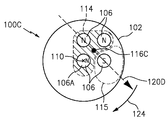
도 4를 참조하면, 5개의 자석(106)이 제거된 것을 제외하고는 도 1 및 2의 영구 자석 비대칭 자기장 시스템(100A)과 실질적으로 동일한 영구 자석 비대칭 자기장 시스템(100C)이 도시되어 있다. 이 실시예에서, 시스템(100C)은 하나의 섭동 지점(116C)을 둘러싸는 4개의 자석(106)들의 하나의 클러스터만을 가지며 몸체는 자석(106A)의 중심을 중심으로 회전한다. 시스템(100C)은 도 1 및 2의 시스템(100A)과 관련하여 위에서 도시되고 설명된 것과 동일한 원리 하에 동일한 방식으로 작동한다. 도 4에 도시된 시스템(100C) 및 도 1 및 2의 시스템(100A)의 차이는, 시스템(100C)의 영구 자석 어레인지먼트(104)가 접선 자기력(120D)을 생성하도록 섭동될 수 있는 하나의 섭동 지점(116C)에 대해서만 비대칭 자기장(114)를 생성하고, 이는 시계 방향(124)의 한 방향으로의 회전을 초래한다는 것이다. 4, there is shown a permanent magnet asymmetric
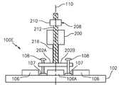
도 5 및 6을 참조하면, 도 1 및 2의 영구 자석 비대칭 자기장 시스템(100A)과 실질적으로 동일한 영구 자석 비대칭 자기장 시스템(100D)이 도시되어 있다. 시스템(100D)은 작동 입력 디바이스(200)를 포함한다. 이 실시예에서, 작동 입력 디바이스(200)는 회전 축(110)과 실질적으로 평행하거나 동일한 작동 회전 축(204)을 중심으로 2개의 작동 암(202A, 202B)(총칭하여 "202")들을 회전시키도록 구성된 출력 샤프트를 갖는 전기 모터이다. 작동 입력 디바이스(200)는 작동 암(202)에 의해 제공되는 작동력 및 작동 타이밍을 제어하도록 구성된 제어기(206)와 작동적으로 통신한다. 전기 모터(200)는 무선 제어 자동차 및 장난감 및 소형 산업용 액추에이터 애플리케이션에 사용되는 것과 유사한, 12볼트 DC 고-rpm, 저토크 직류 모터, 모델 XD-3420, DC 12볼트, 3,000RPM이다. 5 and 6, a permanent magnet asymmetric
도 7을 참조하면, 도 5 및 6의 영구 자석 비대칭 자기장 시스템(100D)과 실질적으로 동일한 영구 자석 비대칭 자기장 시스템(100E)이 도시되어 있다. 시스템(100E)은 작동 암(202)에 힘(또는 압력)을 가하는 힘 보조 디바이스(208)를 포함한다. 힘 보조 디바이스(208)는 나사식 가중 요소(210)의 무게(예를 들어, 2.2 lbs)를 나선형 기어 또는 나선형 기어와 같은 나사형 구동 나사 메커니즘(212)을 통해 분배하여 암(202)에 대해 힘을 핀(108)에 가하도록 한다. 힘 보조 디바이스(208)의 보조는, 회전체(102)의 불균일한 회전을 야기할 섭동 요소(108)들로부터 암(202)들의 분리를 야기하는 진동 또는 교란의 영향을 줄이기 위해 또는 모터를 보조하기 위해, 암(202)들에 의해 핀(108)에 대해 유지된다. 이 실시예에서 힘 보조 디바이스(208)는 "중력" 유형 힘 보조 디바이스이지만, 능동 힘 보조를 이용하는 다른 힘 보조 디바이스들은 현재 개시의 범위 내에 있다. 그 경우에, 모터 샤프트(216) 및 나사 구동 샤프트(212)는 둘 다 암(202A)들을 구동하여 섭동 핀(108)들에 힘을 가한다. Referring to FIG. 7 , a permanent magnet asymmetric
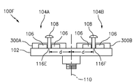
도 8 및 도 9를 참조하면, 영구 자석 비대칭 자기장 시스템(100F)이 현재 개시의 실시예에 따라 도시된다. 시스템(100F)은 회전체(102) 상에 배열된 2개의 영구 자석 어레인지먼트(104A, 104B)들을 포함하고, 각각의 어레인지먼트(104A, 104B)들은 섭동 지점(116E, 116F) 주위에 4개의 영구 자석(106)들을 갖고, 도 3의 시스템(100B)과 유사하게, 동일한 것으로부터 연장하는 섭동 요소(108)를 갖고, 단, 어레인지먼트(104A, 104B)들은 섭동 지점(116E, 116F)들을 둘러싸는 클러스터들(또는 영구 자석 어레인지먼트들)에서 공통 영구 자석을 공유하지 않는다. 어레인지먼트(104A, 104B)들은 회전 축(110)으로부터 방사상으로 오프셋되어 배열된다. 회전 축(110)으로부터 원하는 반경 방향 거리(d), 예를 들어 8인치에 섭동 지점(들)(116)을 위치시키도록 영구 자석 어레인지먼트(들)(104)를 구성하는 것은 현재 개시의 범위 내에 있다. 어레인지먼트(104A, 104B)들의 섭동 및 동작은 실질적으로 다른 실시예들과 관련하여 위에서 논의된 바와 같다. 섭동 지점(116E, 116F)들 중 하나 또는 둘 모두는 비대칭 자기장(들)을 섭동시키기 위해 내부에서 작동되는 섭동 요소(108)를 가질 수 있다. 어레인지먼트(104A, 104B)들 상의 섭동(들)로부터의 결과적인 접선 자기력(320A, 320B)은 회전체(102)가 회전 축(110)을 중심으로 회전하게 할 것이다. 각각의 어레인지먼트(104A, 104B)는 선택적인 하우징(300A, 300B)에 배열된다. 8 and 9 , a permanent magnet asymmetric
각 어레인지먼트(104A, 104B)는 5" 직경의 1/4" 두께의 알루미늄 디스크와 강철로 만들어진 동일한 치수의 하단 플레이트가 있는 5" 외경 x 4" 내경 x 1.5" 높이의 철강 실린더 하우징(300A, 300B)으로 둘러싸여 있다. 그러나, 현재 개시에서 논의된 바와 같이, 다른 하우징(300A, 300B) 구성 형상 및 크기는 현재 개시의 범위 내에 있다. 또한, 위에서 논의된 바와 같이, 하우징(300A, 300B)은 선택적이며 영구 자석(106)은 회전체(102)에 직접 배열되거나 고정될 수 있다. 이 실시예에서, 회전체(102)는 앞서 논의된 80lb 플라이휠이다. 그러나, 다른 회전체(102) 크기, 형상 및 재료는 현재 개시의 범위 내에 있다. 회전체(102)는 철계 또는 비철계 재료로 만들어질 수 있다. Each arrangement (104A, 104B) consists of a 5" OD x 4" ID x 1.5" high steel cylinder housing (300A, 300B) with a 5" diameter 1/4" thick aluminum disk and an equally dimensioned bottom plate made of steel. However, as discussed in the present disclosure,
또한, 도 5내지7에 도시된 섭동 핀(108)들에 대해 가압하기 위해 회전 암을 갖는 모터 드라이브 및/또는 나선형 기어 장치가 도 8 및 9의 이러한 실시예와 함께 사용될 수 있다. Also, a motor drive with a rotating arm and/or a helical gear arrangement with a rotating arm to press against the perturbating pins 108 shown in FIGS. 5-7 may be used with this embodiment of FIGS. 8 and 9 .
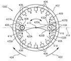
도 10 및 11을 참조하면, 영구 자석 비대칭 자기장 시스템(100G)이 현재 개시의 실시예에 따라 도시된다. 시스템(100G)은 원통형 회전체(402), 복수의 벽 자석(406)들, 2개의 원통형 바이어스 자석들(407A, 407B)(집합적으로 "407") 및 섭동 요소(408)를 포함한다. 회전체(402)는 회전 축(410)을 중심으로 회전하도록 구성된다. 벽 자석(406)들은 회전체(402)의 내주벽(412)에 배치된다. 회전체(402)를 분기하는 가상의 적도(414) 일 측 상의 벽 자석(406)들은 회전 축(410)과 마주하는 면이 북극(N)이고, 가상의 적도(414)의 반대편에 있는 벽 자석(406)들은 남쪽 극성(S)을 갖는 회전 축(410)을 향하는 면을 갖는다. 바이어스 자석(407)들은 회전체(402)의 하단 표면(418) 상의 섭동 지점(416)들에 배열되고, "적도"(414)에 정렬되고 회전 축(410)으로부터 방사상으로 오프셋된다. 하단 표면(418)으로부터 멀어지는 방향을 향하는 바이어스 자석(407)들의 상부 표면은 상이한 극성들을 갖는다. 특히, 바이어스 자석(407A)의 상부 표면은 북극성(N)을 갖고, 바이어스 자석(407B)의 상면은 남극성(S)을 갖는다. 10 and 11 , a permanent magnet asymmetric
일부 실시예들에서, 벽 자석(406)은 길이가 3", 너비가 1/2", 두께가 1/4"인 직사각형 영구 자석이고; 바이어스 자석들은 직경이 1/4”이고 두께가 1/8”인 원통형 자석이고; 하우징의 외경은 4", 내경은 3.5", 높이는 4"이다. 하우징은 상단이 개방되어 있지만 완전히 밀폐된 실린더 또는 원통형 하우징은 직사각형, 타원형, 삼각형 등과 같은 다른 형상과 마찬가지로 현재 개시의 범위 내에 있다. 일부 실시예들에서, 하우징은 철계 재료로 만들어지고 다른 실시예에서 하우징은 비철계 재료로 만들어진다. 일부 실시예들에서, 하우징은 일부 철계 재료 및 일부 비철계 재료, 예를 들어 철계 재료로 만들어진 벽(412) 및 하단 표면(418) 및 비철계 재료로 만들어진 상단을 갖는 원통형 하우징을 갖는다. 그러나, 다른 치수, 형상 및 재료 선택은 현재 개시내용의 범위 내에 있고 애플리케이션이 요구하거나 원하는 대로 변경될 수 있다. In some embodiments, the
벽 자석(406)들 및 바이어스 자석(407)들은 바이어스 자석(407)들 근처에서 적도(414)로부터 벗어나지만, 회전 축(410)이 적도(414)와 교차하는 지점 근처에서 실질적으로 적도(414)와 교차하는 자속 자기장 라인(420A)을 생성한다. 구체적으로, 자속 자기장 라인(420A)은 바이어스 자석(407)의 상부 표면에 반대 극성인 회전 축(410)을 향하는 면을 갖는 벽 자석(406)을 향해 적도(414)로부터 벗어나 있다. 자속 자기장 라인(420A)의 구성은 바이어스 자석(407)들의 위치에 실질적으로 위치된 2개의 섭동 지점(416)들을 야기한다. 바이어스 자석(407)들은 내벽들로부터 회전 중심(410)까지의 거리의 약 3분의 1에 위치될 수 있다. The
작동 시에, 섭동 요소(408)는 섭동 요소(408)의 길이 방향 연장부가 회전 축(410)에 평행하거나 실질적으로 평행하도록 섭동 지점(416)들 중 하나에서(또는 실질적으로에서) 회전체(402) 내로 삽입된다. 그 다음, 섭동 요소(408)는 방향(430A)으로 자속 자기장 라인(420A)을 향해 이동하거나 기울어지도록 작동된다. 섭동 요소의 작동은 비대칭 자속 자기장 라인(420A)을 섭동시키고 벽 자석(406)들, 바이어스 자석(407)들 및/또는 회전 축(410)을 중심으로 회전체(402)에 결과적인 접선 자기력을 생성하고, 접선 자기력이 접선 자기력에 저항하는 마찰 및/또는 하중보다 크다고 가정하여 회전체(402)가 반시계 방향(422)으로 회전 축(410)을 중심으로 회전하게 한다. 다른 실시예와 관련하여 위에서 논의된 바와 같이, 섭동 요소(408)가 두 섭동 지점(416)들에서 동시에 작동되도록 하는 추가 섭동 요소(408)(도시되지 않음)가 있을 수 있으며, 이는 원하는 경우 몸체(402)에 2배의 회전력을 제공할 수 있다. In operation, the
일부 실시예들에서, 바이어스 자석(407)의 상부 표면은 동일한 극성(N-N; 또는 S-S)을 가질 수 있다. 그러한 실시예들에서, N-N 배열의 경우, 자속 자기장 라인은 축(410)의 우측에서 자속 자기장 라인(420B)의 형상을 가질 것이다. 이 구성은 몸체(402)의 양방향 회전을 허용한다. 예를 들어, 바이어스 자석(407A)의 섭동 지점(416)에서 방향(430A)으로 작동되는 섭동 요소(408)는 회전체(402)의 반시계 방향(422) 회전을 야기할 것이고, 반면 바이어스 자석(407B)의 섭동 지점(416)에서, 방향(432B)으로, 섭동 요소(408)의 작동(또는 제2 섭동 요소(408)의 작동)은 회전체(402)의 시계 방향(424) 회전을 야기할 것이다. In some embodiments, the top surface of the bias magnet 407 may have the same polarity (N-N; or S-S). In such embodiments, for an N-N arrangement, the magnetic flux magnetic field line will have the shape of the magnetic flux
2개의 바이어스 자석(407)들 중 하나는 선택 사항이며 제거될 수 있다. 예를 들어, 바이어스 자석(407B)이 제거되면, 자속 자기장 라인(420A)은 실질적으로 단일 바이어스 자석(407A)에서 적도로부터만 벗어날 것이다. 이 실시예에서, 단일 바이어스 자석(407A)에서 단 하나의 섭동 지점(416)이 있을 것이다. One of the two bias magnets 407 is optional and can be removed. For example, if
도 12를 참조하면, 영구 자석 비대칭 자기장 시스템(100H)이 현재 개시의 실시예들에 따라 도시된다. 시스템(100H)은 회전체(502), 도 8 및 9의 어레인지먼트(300A, 300B)들과 유사한 복수의 자석(506)들을 갖는 영구 자석 어레인지먼트(504) 및 섭동 요소(508)를 포함한다. 시스템(100H)은 섭동 요소 개구(512)를 정의하는 섭동 요소 가이드(또는 지지부)(510)를 더 포함한다. 섭동 요소 개구(512)는, 섭동 요소(508)를 수용하도록 구성되고, 섭동 요소(508)가 섭동 축(518)으로부터 벗어나도록 또는 다른 실시예와 관련하여 여기에서 논의된 바와 같이 자속 자기장 라인을 향해 작동되는 경우, 회전체(502)의 움직임을 야기하는 섭동 축(514) 주위에 위치된다. 섭동 요소 가이드(510)는 섭동 축(514)(또는 자속 자기장 라인으로부터의 거리(119)(도 1))으로부터 섭동 요소(508)의 편차 범위를 제한하는 역할을 한다. 가이드(510)는 도 5 내지 7에서와 같이 전기 모터 및/또는 중력 추와 같은 작동 장치에 의해 섭동 요소(508)가 필요하거나 원하는 것보다 더 큰 거리만큼 작동되는 것을 유리하게 방지할 수 있다. 가이드(510)는 또한 섭동 요소(508)가 작동되지 않거나 작동 장치에 의해 유지되지 않을 때 섭동 요소(508)가 자석(506)에 의해 이동되는 것을 방지하기 위한 정지부를 유리하게 구성할 수 있다. 가이드(510)는 구멍(512)을 갖는 덮개 또는 캡일 수 있고, 섭동 요소(508)의 운동 범위를 제한하기 위해 여기의 임의의 실시예와 함께 사용될 수 있다. 12 , a permanent magnet asymmetric
섭동 요소 개구(512)는 원하는 대로 또는 애플리케이션이 요구하는 대로 임의의 크기 또는 모양일 수 있다. 예를 들어, 섭동 요소 개구(512)는 원형 구멍, 직선 슬롯, 곡선 슬롯 또는 지그재그 슬롯일 수 있다. 그러나, 다른 형태는 현재 출원의 범위 내에 있다. Perturbing element opening 512 may be of any size or shape as desired or as required by the application. For example, the
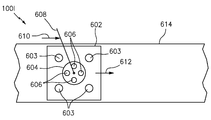
도 13을 참조하면, 위에서 논의된 실시예들은 회전 축을 중심으로 회전하는 회전체를 갖는 시스템과 관련되어 있다. 비회전 운동(예를 들어, 병진 운동 또는 선형 운동)을 생성하는 영구 자석 비대칭 자기장 시스템은 본 개시의 범위 내에 있다. 예를 들어, 도 13을 참조하면, 영구 자석 비대칭 자기장 시스템(100I)이 현재 개시의 실시예에 따라 도시된다. 시스템(100I)은 복수의 베어링들(또는 휠들)(603)을 갖는 선형 운동 몸체(602), 복수의 자석(606)들을 갖는 영구 자석 어레인지먼트(604), 및 섭동 요소(608)를 포함한다. 영구 자석 어레인지먼트(604)는 다른 실시예와 관련하여 위에서 논의된 바와 같이 메이저 자기장 및 마이너 자기장을 생성한다. 섭동 요소(608)가 방향(610)으로 마이너 자기장을 향해 바이어스되거나 이동될 때, 자석(606) 및/또는 선형 운동 몸체(602)에 대한 결과적인 자기력은 선형 운동 몸체(602)가 방향(612)으로 이동하게 한다. 베어링(603)은 선형 운동 몸체(602)가 방향(612)으로 강제 이동될 때 맞닥뜨릴 수 있는 마찰 또는 저항을 감소시키는 역할을 한다. Referring to FIG. 13 , the embodiments discussed above relate to a system having a rotating body that rotates about an axis of rotation. Permanent magnet asymmetric magnetic field systems that produce non-rotational motion (eg, translational or linear motion) are within the scope of the present disclosure. For example, referring to FIG. 13 , a permanent magnet asymmetric magnetic field system 100I is shown in accordance with an embodiment of the present disclosure. System 100I includes a linear moving
선형 운동 몸체(602)는 가드 레일을 가질 수 있는 선택적인 선형 트랙(614)에 배열되는 것으로 도시되어 있다. 선형 트랙(614)은 선형 운동 몸체(602)가 트랙(614)으로부터 임의의 비선형 방향으로 이동하는 것을 방지하기 위해 선형 운동 몸체(602)를 제한한다. 회전 실시예들과 관련하여 위에서 논의된 양방향성은 선형 운동 실시예에도 적용 가능하다. 특히, 섭동 요소(608)(또는 다른 섭동 요소)의 섭동이 선형 운동 몸체(602)가 반대 선형 방향으로 이동하게 하여 시스템(100I)의 순방향 및 역방향 제어를 제공하는 자석 어레인지먼트가 있을 수 있다. The linear moving
현재 개시에 따른 실시예들에서, 자석은 풍력 터빈과 같은 구조물에서 회전을 촉진하도록 작동하도록 배열되며, 이는 풍력 터빈의 회전을 개시하는 데 필요한 입력 에너지를 상당히 감소시킬 수 있다. In embodiments according to the present disclosure, the magnet is arranged to act to promote rotation in a structure such as a wind turbine, which can significantly reduce the input energy required to initiate rotation of the wind turbine.
여기에 제공된 치수는 대략적인 치수이며 여기에 설명된 것과 동일한 기능 및 성능을 제공한다면 원하는 경우 다른 치수를 사용할 수 있다. Dimensions provided herein are approximate and other dimensions may be used if desired provided they provide the same features and performance as those described herein.
여기서 개시된 실시예들에 대해, 비대칭 자기장의 섭동은 영구 자석으로부터의 위치 에너지를 각 또는 선형(병진) 속도 또는 가속도의 형태로 운동 에너지로 방출하게 한다. 우리는 회전 축에 평행하거나 거의 평행한(또는 어레인지먼트의 바닥에 수직인) 섭동 요소에 작용하는 작은 입력 힘이 이러한 에너지 방출(또는 운동 에너지로의 변환)로 인해 증폭된 출력 힘을 유발한다는 것을 발견하였다. For the embodiments disclosed herein, perturbation of the asymmetric magnetic field causes potential energy from the permanent magnet to be released as kinetic energy in the form of angular or linear (translational) velocity or acceleration. We find that a small input force acting on a perturbing element parallel or nearly parallel to the axis of rotation (or perpendicular to the bottom of the arrangement) causes an amplified output force due to this energy release (or conversion into kinetic energy). did.
특정 영구 자석 어레인지먼트가 섭동 지점(들)에 대해 비대칭 자기장(들)을 생성하는 것으로 도시되고 설명되었지만, 영구 자석 어레인지먼트가 섭동 지점(들)에 대해 비대칭 자기장을 생성하도록 구성되는 한, 영구 자석 어레인지먼트가 사실상 임의의 다른 형상 또는 구성, 또는 자석의 개수가 되는 것은 본 개시의 범위 내에 있다. 예를 들어, 달리 섭동 지점(들)에 대해 대칭 자기장을 생성하지만 자기장 차폐, 간섭 또는 전환 구조(들)가 존재하는 영구 자석 어레인지먼트는 현재 개시의 범위 내에 있으며, 즉 자기장 차폐, 간섭 또는 전환 구조(들)는 궁극적으로 영구 자석 어레인지먼트가 섭동 지점(들)에 대해 비대칭 자기장을 생성하도록 한다. Although certain permanent magnet arrangements have been shown and described as producing an asymmetric magnetic field(s) with respect to a point(s) of perturbation, insofar as the arrangement is configured to produce an asymmetric magnetic field with respect to a point(s) of perturbation, a permanent magnet arrangement may It is within the scope of this disclosure to be of virtually any other shape or configuration, or number of magnets. For example, permanent magnet arrangements that otherwise produce a symmetrical magnetic field with respect to the perturbation point(s) but with magnetic field shielding, interference or diverting structure(s) are within the scope of the present disclosure, i.e., magnetic field shielding, interference or diverting structures ( ) ultimately causes the permanent magnet arrangement to create an asymmetrical magnetic field with respect to the perturbation point(s).
여기에서 보여지고 설명된 자기장 라인들은 자기장 위치의 근사치이다. 자기장 또는 자기장 라인의 실제 모양과 위치는 표시된 것과 다를 수 있고/있거나 시스템의 물리적 특성 및 재료에 따라 다를 수 있다. The magnetic field lines shown and described herein are approximations of magnetic field positions. The actual shape and location of the magnetic field or magnetic field lines may differ from those shown and/or may differ depending on the physical properties and materials of the system.
여기에 설명된 시스템 및 방법의 자석의 자기 극성은 반전될 수 있고 동일한 의도된 기능 및 구조를 달성할 수 있다는 것을 쉽게 이해해야 한다. 구체적으로, 북극 N 극성을 갖는 자석 측(또는 표면)은 대신 남극 S 극성을 가질 수 있고, 남극 S 극성을 갖는 자석 측(또는 표면)은 대신 북극 N 극성을 가질 수 있으며, 영구 자석 비대칭 시스템 및 방법은 본 명세서에 개시된 것과 실질적으로 동일하게 기능할 것이다. It should be readily understood that the magnetic polarity of the magnets of the systems and methods described herein can be reversed and achieve the same intended function and structure. Specifically, the magnet side (or surface) with north pole N polarity may instead have south pole S polarity, and the magnet side (or surface) with south pole S polarity may instead have north pole N polarity, and a permanent magnet asymmetric system and The method will function substantially the same as disclosed herein.
현재 개시에서는 영구 자석이 원형 평면 자석, 원통형 자석 및 막대 자석인 것으로 도시 및 설명하였지만, 임의의 영구 자석 형상이 현재 개시내용의 범위 내에 있음을 쉽게 이해해야 한다. 자석은 모양과 유형이 다를 수 있다. 예를 들어, 원통형 자석들은 원통형 자석(들)의 길이 방향으로 중앙 보어 또는 구멍이 내부에 정의된 실린더 및/또는 실린더일 수 있다. 중앙 보어(또는 그에 추가하여) 대신에, 자석들에 블라인드 보어들이 제공될 수 있다. 자석들은 자기장을 강화하거나 원하는 자기장을 생성하기 위해 필요한 중심 구멍 및/또는 블라인드 구멍으로 구성될 수 있다. 직사각형 자석들 또는 평면 자석들과 같은 다른 자석 모양은 향상 또는 원하는 자기장 모양/강도를 위해 가로(두께를 통해) 보어 또는 구멍 또는 블라인드 보어를 가질 수 있다. 또한, 다양한 자석들이 별개의 자석들인 것으로 설명되었지만, 자석들이 단일의 단일 피스 또는 구조를 형성하는 것은 현재 개시내용의 범위 내에 있다. 또한, 여기에 설명된 임의의 주어진 영구 자석은 원하는 경우 주어진 영구 자석과 동일한 기능 및 극성을 수행하도록 함께 적층되는 복수의 더 작은 영구 자석들을 포함할 수 있다. Although the present disclosure has illustrated and described permanent magnets as circular planar magnets, cylindrical magnets, and bar magnets, it should be readily understood that any permanent magnet shape is within the scope of the present disclosure. Magnets can be of different shapes and types. For example, the cylindrical magnets may be cylinders and/or cylinders having a central bore or hole defined therein in the longitudinal direction of the cylindrical magnet(s). Instead of (or in addition to) a central bore, the magnets may be provided with blind bores. The magnets may be configured with a central hole and/or a blind hole as necessary to enhance the magnetic field or create a desired magnetic field. Other magnet shapes such as rectangular magnets or planar magnets may have a transverse (through thickness) bore or hole or blind bore for enhancement or desired magnetic field shape/strength. Also, although various magnets have been described as being separate magnets, it is within the scope of the present disclosure for the magnets to form a single single piece or structure. Also, any given permanent magnet described herein may include a plurality of smaller permanent magnets stacked together to perform the same function and polarity as the given permanent magnet, if desired.
발명이 예시적인 실시예들과 관련하여 설명되고 예시되었지만, 전술한 것과 다양한 다른 추가 및 생략이 현재 개시의 정신 및 범위를 벗어나지 않고 그 안에 그리고 거기에 만들어질 수 있다. 여기서 명시적으로 또는 묵시적으로 달리 명시되지 않는 한, 여기서의 특정 실시예에 관한 임의의 특징, 특징, 대안 또는 수정이 본 명세서에 기재된 임의의 다른 실시예와 함께 적용, 사용 또는 통합될 수 있음을 이해해야 한다. While the invention has been described and illustrated in connection with exemplary embodiments, various other additions and omissions to those described above may be made therein and therein without departing from the spirit and scope of the present disclosure. Unless expressly or implied otherwise specified herein, any feature, feature, alternative or modification with respect to a particular embodiment herein may be applied, used, or incorporated with any other embodiment described herein. you have to understand
Claims (21)
회전 축을 중심으로 회전하도록 구성된 회전체;
2개 이상의 영구 자석들을 포함하는 상기 회전체 상에 배열된 영구 자석 어레인지먼트; 및
섭동 요소;
를 포함하고,
상기 영구 자석 어레인지먼트는 섭동 지점 주위의 상기 영구 자석들에 의해 비대칭 자기장이 생성되도록 구성되고;
입력 힘으로 상기 섭동 지점에서 또는 그 근처에서 상기 섭동 요소의 작동은, 상기 회전체 또는 상기 영구 자석 어레인지먼트에 접선 자기 출력 힘을 발생시켜, 상기 회전체가 상기 회전 축을 중심으로 회전하게 하고;
상기 섭동 요소의 상기 작동은 상기 비대칭 자기장의 섭동을 유발하여, 상기 영구 자석 어레인지먼트로부터 위치 에너지를 방출하여, 상기 회전을 유발하는 상기 출력 힘을 생성하는,
영구 자석 비대칭 자기장 시스템.
A permanent magnet asymmetric magnetic field system for moving a body, comprising:
a rotating body configured to rotate about an axis of rotation;
a permanent magnet arrangement arranged on the rotating body comprising two or more permanent magnets; and
perturbation factor;
including,
the permanent magnet arrangement is configured such that an asymmetric magnetic field is created by the permanent magnets around a point of perturbation;
actuation of the perturbating element at or near the point of perturbation with an input force generates a tangential magnetic output force in the rotating body or the permanent magnet arrangement, causing the rotating body to rotate about the axis of rotation;
said actuation of said perturbing element causes perturbation of said asymmetric magnetic field, releasing potential energy from said permanent magnet arrangement, thereby generating said output force causing said rotation;
Permanent magnet asymmetric magnetic field system.
상기 섭동 요소는 철계 재료를 포함하는,
영구 자석 비대칭 자기장 시스템.
According to claim 1,
wherein the perturbating element comprises an iron-based material;
Permanent magnet asymmetric magnetic field system.
상기 섭동 요소는 철을 포함하는,
영구 자석 비대칭 자기장 시스템.
3. The method of claim 2,
wherein the perturbating element comprises iron;
Permanent magnet asymmetric magnetic field system.
상기 섭동 요소는 자석을 포함하는,
영구 자석 비대칭 자기장 시스템.
According to claim 1,
wherein the perturbing element comprises a magnet;
Permanent magnet asymmetric magnetic field system.
상기 자석은 원추형 자석인,
영구 자석 비대칭 자기장 시스템.
5. The method of claim 4,
The magnet is a conical magnet,
Permanent magnet asymmetric magnetic field system.
상기 영구 자석 어레인지먼트는 상기 섭동 지점 주위에 배열된 4개의 자석들을 포함하고, 상기 4개의 자석들 중 3개의 자석들은 제1 극성을 공유하는 상기 회전체로부터 반대 방향을 향하는 측을 갖고, 상기 4개의 자석 중 하나의 자석은 제2 극성을 갖는 상기 회전체로부터 반대 방향을 향하는 측을 갖는,
영구 자석 비대칭 자기장 시스템.
According to claim 1,
The permanent magnet arrangement comprises four magnets arranged around the point of perturbation, three of the four magnets having a side facing away from the body of rotation sharing a first polarity, one of the magnets has a side facing away from the body of rotation having a second polarity,
Permanent magnet asymmetric magnetic field system.
상기 섭동 요소를 작동시키도록 구성된 작동 입력 디바이스를 더 포함하는,
영구 자석 비대칭 자기장 시스템.
According to claim 1,
further comprising an actuation input device configured to actuate the perturbing element;
Permanent magnet asymmetric magnetic field system.
상기 작동 입력 디바이스는 전기 모터인,
영구 자석 비대칭 자기장 시스템.
8. The method of claim 7,
wherein the actuation input device is an electric motor;
Permanent magnet asymmetric magnetic field system.
상기 비대칭 자기장은 메이저 자기장 및 마이너 자기장을 포함하고, 상기 메이저 자기장은 상기 마이너 자기장보다 크거나 및/또는 상기 메이저 자기장은 상기 마이너 자기장보다 더 큰 자기장 강도를 갖는,
영구 자석 비대칭 자기장 시스템.
According to claim 1,
wherein the asymmetric magnetic field comprises a major magnetic field and a minor magnetic field, the major magnetic field having a magnetic field strength greater than the minor magnetic field and/or the major magnetic field having a magnetic field strength greater than the minor magnetic field;
Permanent magnet asymmetric magnetic field system.
상기 섭동 지점 또는 그 근처에서 상기 섭동 요소의 작동은 상기 섭동 요소가 섭동 축으로부터 벗어나게 하고, 상기 섭동 축은 회전 축에 실질적으로 평행하는,
영구 자석 비대칭 자기장 시스템.
10. The method of claim 9,
actuation of the perturbation element at or near the point of perturbation causes the perturbation element to deviate from an axis of perturbation, the axis of perturbation being substantially parallel to the axis of rotation;
Permanent magnet asymmetric magnetic field system.
회전 축을 중심으로 회전하도록 구성된 회전체;
2개 이상의 영구 자석들을 포함하는 상기 회전체 상에 배열된 영구 자석 어레인지먼트; 및
제1 섭동 요소;
를 포함하고,
상기 영구 자석 어레인지먼트는 비대칭 자기장이 복수의 섭동 지점들 주위의 상기 영구 자석들에 의해 생성되도록 구성되고;
상기 섭동 지점들 중 하나에서 또는 그 근처에서 상기 제1 섭동 요소의 작동은 상기 회전체 및/또는 상기 영구 자석 어레인지먼트에 제1 접선 자기력을 발생시켜, 상기 회전체가 상기 회전 축을 중심으로 회전하게 하는,
영구 자석 비대칭 자기장 시스템.
A permanent magnet asymmetric magnetic field system for rotating a body, comprising:
a rotating body configured to rotate about an axis of rotation;
a permanent magnet arrangement arranged on the rotating body comprising two or more permanent magnets; and
a first perturbation element;
including,
the permanent magnet arrangement is configured such that an asymmetric magnetic field is generated by the permanent magnets around a plurality of perturbation points;
Actuation of the first perturbing element at or near one of the perturbation points generates a first tangential magnetic force in the rotating body and/or the permanent magnet arrangement, causing the rotating body to rotate about the axis of rotation. ,
Permanent magnet asymmetric magnetic field system.
제2 섭동 요소를 더 포함하고,
상기 섭동 지점들 중 하나에서 또는 그 근처에서 상기 제2 섭동 요소의 작동은 상기 회전체 및/또는 상기 영구 자석 어레인지먼트에 제2 접선 자기력을 발생시켜, 상기 회전체가 상기 회전 축을 중심으로 회전하게 하고, 상기 제1 접선 자기력 및 상기 제2 접선 자기력은 상기 회전체가 동일한 방향으로 회전하도록 하는,
영구 자석 비대칭 자기장 시스템.
12. The method of claim 11,
a second perturbation element,
Actuation of the second perturbing element at or near one of the perturbation points generates a second tangential magnetic force in the rotating body and/or the permanent magnet arrangement, causing the rotating body to rotate about the axis of rotation; , The first tangential magnetic force and the second tangential magnetic force to rotate the rotating body in the same direction,
Permanent magnet asymmetric magnetic field system.
복수의 섭동 지점들은 적어도 4개의 섭동 지점들을 포함하고, 상기 적어도 4개의 섭동 지점들의 제1 쌍에서 상기 제1 섭동 요소의 작동은 상기 회전체가 제1 방향으로 회전하게 하고, 상기 적어도 4개의 섭동 지점들의 제2 쌍에서 상기 제1 섭동 요소의 작동은 상기 회전체가 제2 방향으로 회전하게 하고, 상기 제2 방향은 상기 제1 방향과 반대인,
영구 자석 비대칭 자기장 시스템.
12. The method of claim 11,
the plurality of perturbation points comprises at least four perturbation points, wherein actuation of the first perturbation element at the first pair of at least four perturbation points causes the rotating body to rotate in a first direction, wherein the at least four perturbation points cause the rotating body to rotate in a first direction; actuation of the first perturbating element at a second pair of points causes the rotating body to rotate in a second direction, the second direction opposite to the first direction;
Permanent magnet asymmetric magnetic field system.
상기 비대칭 자기장은 메이저 자기장 및 마이너 자기장을 포함하고, 상기 메이저 자기장은 상기 마이너 자기장보다 크고 및/또는 상기 메이저 자기장은 상기 마이너 자기장보다 더 큰 자기장 강도를 갖는,
영구 자석 비대칭 자기장 시스템.
12. The method of claim 11,
wherein the asymmetric magnetic field comprises a major magnetic field and a minor magnetic field, the major magnetic field having a magnetic field strength greater than the minor magnetic field and/or the major magnetic field having a magnetic field strength greater than the minor magnetic field;
Permanent magnet asymmetric magnetic field system.
상기 섭동 지점 또는 그 근처에서 상기 섭동 요소의 작동은 상기 섭동 요소가 섭동 축으로부터 벗어나게 하고, 상기 섭동 축은 상기 회전 축에 실질적으로 평행하는,
영구 자석 비대칭 자기장 시스템.
15. The method of claim 14,
actuation of the perturbation element at or near the point of perturbation causes the perturbation element to deviate from an axis of perturbation, the axis of perturbation being substantially parallel to the axis of rotation;
Permanent magnet asymmetric magnetic field system.
회전 축을 중심으로 회전하도록 구성된 회전체;
2개 이상의 영구 자석들을 포함하는 상기 회전체 상에 배열된 영구 자석 어레인지먼트; 및
섭동 요소;
를 포함하는, 영구 자석 비대칭 자기장 시스템을 제공하는 단계;
상기 섭동 요소를 섭동 지점에서 또는 그 근처에서 작동시켜, 상기 회전체 및/또는 상기 영구 자석 어레인지먼트에 접선 자기력을 발생시켜, 상기 회전체가 회전 축을 중심으로 회전하게 하는 단계;
를 포함하고,
상기 영구 자석 어레인지먼트는 섭동 지점 주위의 영구 자석에 의해 비대칭 자기장이 생성되도록 구성되는,
방법.
A method of perturbing a permanent magnet asymmetric magnetic field system to move a body, the method comprising:
a rotating body configured to rotate about an axis of rotation;
a permanent magnet arrangement arranged on the rotating body comprising two or more permanent magnets; and
perturbation factor;
providing a permanent magnet asymmetric magnetic field system comprising:
actuating the perturbating element at or near the perturbation point to generate a tangential magnetic force in the rotating body and/or the permanent magnet arrangement, causing the rotating body to rotate about an axis of rotation;
including,
wherein the permanent magnet arrangement is configured such that an asymmetric magnetic field is created by the permanent magnet around the point of perturbation;
Way.
상기 섭동 요소의 상기 작동은 상기 섭동 요소가 섭동 축으로부터 벗어나게 하고, 상기 섭동 축은 상기 회전 축에 실질적으로 평행한,
방법.
17. The method of claim 16,
the actuation of the perturbation element causes the perturbation element to deviate from an axis of perturbation, the axis of perturbation being substantially parallel to the axis of rotation;
Way.
상기 섭동 요소를 작동시키는 단계는, 상기 섭동 요소의 길이 방향 연장이 상기 섭동 지점에서 상기 회전체의 표면에 수직인 초기 위치로부터 상기 섭동 요소를 작동시키는,
방법.
17. The method of claim 16,
actuating the perturbation element comprises actuating the perturbation element from an initial position in which the longitudinal extension of the perturbation element is perpendicular to the surface of the rotating body at the perturbation point;
Way.
상기 섭동 요소의 상기 작동은 전기 모터에 의해 구동되는 작동 암에 의해 수행되는,
방법.
17. The method of claim 16,
the actuation of the perturbing element is performed by an actuating arm driven by an electric motor;
Way.
상기 전기 모터는 작동 회전 축을 중심으로 상기 작동 암을 회전시키도록 구성되고, 상기 작동 회전 축은 상기 회전 축에 실질적으로 평행한,
방법.
20. The method of claim 19,
the electric motor is configured to rotate the actuating arm about an actuating axis of rotation, the actuating axis of rotation being substantially parallel to the axis of rotation;
Way.
회전 축을 중심으로 회전하도록 구성된 회전체;
2개 이상의 영구 자석들을 포함하는 상기 회전체 상에 배열된 영구 자석 어레인지먼트; 및
섭동 요소;
를 포함하고,
상기 영구 자석 어레인지먼트는 섭동 지점 주위의 상기 영구 자석들에 의해 비대칭 자기장이 생성되도록 구성되고;
입력 힘으로 상기 섭동 지점에서 또는 그 근처에서 상기 섭동 요소의 작동은, 상기 회전체 또는 상기 영구 자석 어레인지먼트 상에 접선 자기 출력 힘을 발생시켜, 상기 회전체가 상기 회전 축을 중심으로 회전하게 하고;
상기 섭동 요소의 상기 작동은 상기 비대칭 자기장의 섭동을 유발하여, 상기 영구 자석 어레인지먼트로부터 위치 에너지를 방출하여, 상기 회전을 유발하는 상기 출력 힘을 생성하고, 상기 입력 힘은 상기 출력 힘보다 작은,
영구 자석 비대칭 자기장 시스템.
A permanent magnet asymmetric magnetic field system for moving a body, comprising:
a rotating body configured to rotate about an axis of rotation;
a permanent magnet arrangement arranged on the rotating body comprising two or more permanent magnets; and
perturbation factor;
including,
the permanent magnet arrangement is configured such that an asymmetric magnetic field is created by the permanent magnets around a point of perturbation;
actuation of the perturbing element at or near the point of perturbation with an input force generates a tangential magnetic output force on the rotating body or the permanent magnet arrangement, causing the rotating body to rotate about the axis of rotation;
said actuation of said perturbing element causes perturbation of said asymmetric magnetic field, releasing potential energy from said permanent magnet arrangement to produce said output force causing said rotation, said input force being less than said output force;
Permanent magnet asymmetric magnetic field system.
Applications Claiming Priority (3)
| Application Number | Priority Date | Filing Date | Title |
|---|---|---|---|
| US201962917940P | 2019-01-09 | 2019-01-09 | |
| US62/917,940 | 2019-01-09 | ||
| PCT/IB2020/052039 WO2020144668A1 (en) | 2019-01-09 | 2020-03-09 | System and method for perturbing a permanent magnet asymmetric field to move a body |
Publications (1)
| Publication Number | Publication Date |
|---|---|
| KR20210129044A true KR20210129044A (en) | 2021-10-27 |
Family
ID=71520717
Family Applications (1)
| Application Number | Title | Priority Date | Filing Date |
|---|---|---|---|
| KR1020217024871A KR20210129044A (en) | 2019-01-09 | 2020-03-09 | Systems and methods for perturbing permanent magnet asymmetric magnetic fields |
Country Status (9)
| Country | Link |
|---|---|
| US (3) | US11017927B2 (en) |
| EP (1) | EP3921856A4 (en) |
| JP (1) | JP2022517575A (en) |
| KR (1) | KR20210129044A (en) |
| CN (1) | CN113574616A (en) |
| AU (1) | AU2020207027A1 (en) |
| CA (1) | CA3125891C (en) |
| MX (1) | MX2021008333A (en) |
| WO (1) | WO2020144668A1 (en) |
Families Citing this family (1)
| Publication number | Priority date | Publication date | Assignee | Title |
|---|---|---|---|---|
| WO2023055911A1 (en) * | 2021-09-30 | 2023-04-06 | Green Wave Power Systems Llc | System and method for generating rotation of a body to generate energy and reduce climate change |
Family Cites Families (59)
| Publication number | Priority date | Publication date | Assignee | Title |
|---|---|---|---|---|
| US3573517A (en) | 1970-03-02 | 1971-04-06 | Sargentwelch Scient Co | Magnetic drive |
| DE2423573C3 (en) * | 1974-05-15 | 1978-08-31 | Mrt Magnet-Regeltechnik Gmbh, 2000 Hamburg | Magnetically operated control device |
| US4795929A (en) | 1986-08-01 | 1989-01-03 | Logus Manufacturing Corp. | Rotary actuator |
| US4944270A (en) | 1987-03-31 | 1990-07-31 | Akira Matsushita | Asymmetrical excitation type magnetic device and method of manufacture thereof |
| US4843268A (en) * | 1987-09-17 | 1989-06-27 | Marketing Systems Of The South, Inc. | Asymmetric field electromagnetic motor |
| IT1219228B (en) | 1988-04-21 | 1990-05-03 | Antonino Fratta | SYNCHRONOUS RELUCTANCE ELECTRICAL MACHINE EQUIPPED WITH INTRINSIC POWER SUPPLY MEANS |
| US4991836A (en) * | 1989-01-19 | 1991-02-12 | Benjamin Joffe | Dynamic game apparatus and method using multiple magnets and a magnetic manipulator below them |
| US5304881A (en) * | 1989-03-13 | 1994-04-19 | Magnetic Revolutions, Inc. | Means for producing rotary motion |
| DE3931611A1 (en) | 1989-09-22 | 1990-03-22 | Erich Schiek | Rotational force intensifier using permanent magnets - maintaining torque and RPM by aligned and directed magnetic fields with motor or muscle power starting |
| DE4102102C2 (en) * | 1991-01-25 | 1995-09-07 | Leybold Ag | Magnet arrangement with at least two permanent magnets and their use |
| DE69310160T2 (en) * | 1993-06-14 | 1997-10-02 | Nihon Riken Co Ltd | Power generation device |
| US5896961A (en) | 1995-10-02 | 1999-04-27 | Kabushiki Kaisha Toshiba | Dynamic vibration absorber |
| JP2002091691A (en) | 2000-09-20 | 2002-03-29 | Nagano Fujitsu Component Kk | Pointing device |
| JP3684016B2 (en) | 1997-01-28 | 2005-08-17 | ペンタックス株式会社 | Two-dimensional light deflector |
| JPH10221114A (en) | 1997-02-10 | 1998-08-21 | Mitsubishi Electric Corp | Detecting device |
| KR100281474B1 (en) | 1997-05-16 | 2001-02-01 | 후지타 히토시 | Energy extracting mechanism having a magnetic spring |
| US6084496A (en) | 1997-06-27 | 2000-07-04 | Matsushita Electric Industrial Co., Ltd. | Magnetizing method for a permanent-magnet motor |
| JPH11103546A (en) | 1997-09-29 | 1999-04-13 | Fujitsu General Ltd | Permanent magnet motor |
| US6054788A (en) | 1998-08-12 | 2000-04-25 | Reliance Electric Industrial Company | Magnetic power transmission coupling |
| US6330467B1 (en) | 1999-02-04 | 2001-12-11 | Stereotaxis, Inc. | Efficient magnet system for magnetically-assisted surgery |
| GB0007743D0 (en) * | 2000-03-31 | 2000-05-17 | Kelsey Hayes Co | Actuator |
| US6682430B2 (en) | 2001-03-15 | 2004-01-27 | Magnadrive Corporation | Adjustable magnetic coupler |
| US7014811B2 (en) | 2001-07-02 | 2006-03-21 | Neomax Co., Ltd. | Method for producing rare earth sintered magnets |
| US6577037B2 (en) | 2001-07-03 | 2003-06-10 | Magnadrive Corporation | Self-unloading magnetic coupler |
| US6703829B2 (en) | 2001-09-07 | 2004-03-09 | Jeff Tola | Magnetic position sensor |
| US6954019B2 (en) * | 2001-11-13 | 2005-10-11 | M International, Llc | Apparatus and process for generating energy |
| DE20220455U1 (en) | 2001-11-15 | 2003-09-04 | Karl Heinz Linnig Gmbh & Co Kg | Device for damping torsional vibrations |
| FR2852162B1 (en) | 2003-03-06 | 2005-09-23 | Leroy Somer Moteurs | ROTATING ELECTRIC MACHINE COMPRISING A STATOR AND TWO ROTORS |
| JP4269961B2 (en) | 2003-03-31 | 2009-05-27 | 株式会社デンソー | Rotation angle detector |
| US7348754B2 (en) * | 2003-04-10 | 2008-03-25 | Gorur Narayana Srinivasa | Motion control using electromagnetic forces |
| US20040251757A1 (en) | 2003-06-10 | 2004-12-16 | Porter James M. | High efficiency torque converter |
| KR20040096994A (en) | 2004-10-13 | 2004-11-17 | 권순태 | The Principle of Torque Amplification |
| US7453177B2 (en) | 2004-11-19 | 2008-11-18 | Magnadrive Corporation | Magnetic coupling devices and associated methods |
| EP1670126B1 (en) * | 2004-12-10 | 2011-05-04 | Thomson Licensing SA | Electric motor |
| CN102017375A (en) | 2007-06-25 | 2011-04-13 | 奈斯科能量有限责任公司 | Linear permanent magnet motor |
| EP2375098A3 (en) | 2007-12-19 | 2018-02-14 | Koninklijke Philips N.V. | Magnetic spring system in a resonant motor |
| US7994674B2 (en) * | 2008-01-25 | 2011-08-09 | Mcclellan W Thomas | Flux-focused shaped permanent magnet, magnetic unit having the magnets, device having the magnetic units and method for asymmetrically focusing flux fields of permanent magnets |
| US7821168B2 (en) | 2008-02-10 | 2010-10-26 | Empire Magnetics Inc. | Axial gap dynamo electric machine with magnetic bearing |
| JP5215387B2 (en) | 2008-05-21 | 2013-06-19 | 株式会社プロスパイン | Magnetic coupling device |
| JP5129183B2 (en) | 2009-03-13 | 2013-01-23 | 公益財団法人鉄道総合技術研究所 | Magnetic coupling clutch device |
| US8704626B2 (en) | 2010-05-10 | 2014-04-22 | Correlated Magnetics Research, Llc | System and method for moving an object |
| WO2011057423A1 (en) | 2009-11-10 | 2011-05-19 | 俊佳有限公司 | Permanent magnet motion-creating apparatus and process |
| CN101814871B (en) * | 2010-04-12 | 2011-09-21 | 西南交通大学 | Direct-current static and dynamic symmetric/asymmetric magnetic field generating device |
| US9062654B2 (en) | 2012-03-26 | 2015-06-23 | American Wind Technologies, Inc. | Modular micro wind turbine |
| US9331534B2 (en) | 2012-03-26 | 2016-05-03 | American Wind, Inc. | Modular micro wind turbine |
| WO2013159113A1 (en) | 2012-04-20 | 2013-10-24 | Regenedyne LLC | Magnet configurations for magnetic levitation of wind turbines and other apparatus |
| US10173143B2 (en) | 2013-01-31 | 2019-01-08 | Joshua Willard Ferguson | Magnetic construction system and method |
| US10125814B2 (en) * | 2013-10-24 | 2018-11-13 | Raymond James Walsh | Passive magnetic bearing |
| US10110109B2 (en) | 2014-06-11 | 2018-10-23 | Aston Gustavous Farquharson | Self-powered alternative energy machine to generate electricity |
| WO2016089226A1 (en) | 2014-12-04 | 2016-06-09 | Eddy Current Limited Partnership | Methods of altering eddy current interactions |
| JP6577754B2 (en) | 2015-05-26 | 2019-09-18 | 日本電産サンキョー株式会社 | Magnetic coupling mechanism and pump device provided with the same |
| US9960647B2 (en) | 2015-10-01 | 2018-05-01 | Vanntec Llc | Enhanced flux-density magnet |
| US10305360B2 (en) | 2015-11-13 | 2019-05-28 | Magnadrive Corporation | Magnet to magnet couplings and drives |
| US10971292B2 (en) * | 2016-12-07 | 2021-04-06 | University Of Florida Research Foundation, Inc. | Axisymmetric electropermanent magnets |
| US10833558B2 (en) * | 2016-12-08 | 2020-11-10 | Tdk Taiwan Corp. | Multi-directional vibration actuator |
| KR102065450B1 (en) | 2018-06-14 | 2020-01-13 | 정길용 | Disk type magnetic coupling |
| US11732769B2 (en) | 2019-01-09 | 2023-08-22 | Green Wave Power Systems Llc | Magnetically-coupled torque-assist apparatus |
| KR102302463B1 (en) | 2019-04-26 | 2021-09-15 | 한국전자기술연구원 | Magnetic coupling |
| US20220186732A1 (en) | 2020-12-11 | 2022-06-16 | Sapphire Motors | Integrated pump assembly with one moving part with stacked stator |
-
2020
- 2020-03-09 KR KR1020217024871A patent/KR20210129044A/en unknown
- 2020-03-09 CA CA3125891A patent/CA3125891C/en active Active
- 2020-03-09 MX MX2021008333A patent/MX2021008333A/en unknown
- 2020-03-09 EP EP20738431.4A patent/EP3921856A4/en active Pending
- 2020-03-09 JP JP2021539948A patent/JP2022517575A/en active Pending
- 2020-03-09 CN CN202080008629.4A patent/CN113574616A/en active Pending
- 2020-03-09 WO PCT/IB2020/052039 patent/WO2020144668A1/en unknown
- 2020-03-09 AU AU2020207027A patent/AU2020207027A1/en not_active Abandoned
- 2020-12-31 US US17/139,458 patent/US11017927B2/en active Active
-
2021
- 2021-05-21 US US17/326,609 patent/US11250978B2/en active Active
-
2022
- 2022-02-10 US US17/668,439 patent/US11776722B2/en active Active
Also Published As
| Publication number | Publication date |
|---|---|
| EP3921856A4 (en) | 2022-08-24 |
| JP2022517575A (en) | 2022-03-09 |
| MX2021008333A (en) | 2021-08-11 |
| CN113574616A (en) | 2021-10-29 |
| US11017927B2 (en) | 2021-05-25 |
| US20220270798A1 (en) | 2022-08-25 |
| US11776722B2 (en) | 2023-10-03 |
| US20210335528A1 (en) | 2021-10-28 |
| US11250978B2 (en) | 2022-02-15 |
| AU2020207027A1 (en) | 2021-09-02 |
| CA3125891C (en) | 2022-07-12 |
| CA3125891A1 (en) | 2020-07-16 |
| EP3921856A1 (en) | 2021-12-15 |
| WO2020144668A1 (en) | 2020-07-16 |
| US20210125764A1 (en) | 2021-04-29 |
Similar Documents
| Publication | Publication Date | Title |
|---|---|---|
| US7557480B2 (en) | Communicating magnetic flux across a gap with a rotating body | |
| JP5535242B2 (en) | Power generation equipment with improved power generation efficiency and rotational power | |
| US20200386289A1 (en) | Magnetically-coupled torque-assist apparatus | |
| US20080174121A1 (en) | Gravitational magnetic energy convertor | |
| KR20150008138A (en) | Magnet configurations for magnetic levitation of wind turbines and other apparatus | |
| US20150123451A1 (en) | Drive System | |
| KR20210129044A (en) | Systems and methods for perturbing permanent magnet asymmetric magnetic fields | |
| JP2005232965A (en) | Kinetic energy acceleration amplifying device | |
| JPS6281970A (en) | Spherical motor | |
| JP2021182838A (en) | Magnetic power generation/electric (automatic propulsion) system (no need for thermal power, hydraulic power, wind power, nuclear power, etc.) | |
| US20040020667A1 (en) | Magnetic impact device and method for magnetically generating impact motion | |
| US9148046B2 (en) | Method and device for torque generation based on electromagnetic effect | |
| CN104993734B (en) | A kind of moving-magnetic type mangneto micro-displacement driver | |
| CH713990B1 (en) | Vehicle flywheel battery with a 5-degree hybrid magnetic bearing. | |
| JP5228606B2 (en) | Load device | |
| KR102554068B1 (en) | Rotational Energy Conversion | |
| US11646630B2 (en) | System and method for generating rotation of a body to generate energy and reduce climate change | |
| US20230268787A1 (en) | Self Propelling System and Reaction Wheel Device | |
| KR102179119B1 (en) | Wind Rotate Apparatus | |
| CN202076967U (en) | Single or double stator magnetic power machine with permanent magnetic pole equivalent coils | |
| JPH11262239A (en) | Magnetic force rotating apparatus | |
| KR200191030Y1 (en) | A magnetic lift | |
| RU2340025C1 (en) | Method of controlling pulling force of magnetic drive armature | |
| Li et al. | Finite Element Analysis of A new Multi-DOF Flexible Micro-Displacement Manipulator Based on Ferrofluid | |
| RU2320517C2 (en) | Method of forming lifting force |