KR20210122152A - Edge cleaning brushes for floor cleaner - Google Patents
Edge cleaning brushes for floor cleaner Download PDFInfo
- Publication number
- KR20210122152A KR20210122152A KR1020210039319A KR20210039319A KR20210122152A KR 20210122152 A KR20210122152 A KR 20210122152A KR 1020210039319 A KR1020210039319 A KR 1020210039319A KR 20210039319 A KR20210039319 A KR 20210039319A KR 20210122152 A KR20210122152 A KR 20210122152A
- Authority
- KR
- South Korea
- Prior art keywords
- brush
- cleaning
- hub
- cleaning tool
- tensioner
- Prior art date
Links
- 238000004140 cleaning Methods 0.000 title claims abstract description 316
- 230000008878 coupling Effects 0.000 claims abstract description 40
- 238000010168 coupling process Methods 0.000 claims abstract description 40
- 238000005859 coupling reaction Methods 0.000 claims abstract description 40
- 239000012530 fluid Substances 0.000 claims description 18
- 239000010813 municipal solid waste Substances 0.000 claims description 11
- 238000000034 method Methods 0.000 claims description 10
- 238000004891 communication Methods 0.000 claims description 6
- 239000002699 waste material Substances 0.000 description 12
- 239000000463 material Substances 0.000 description 11
- 238000010408 sweeping Methods 0.000 description 9
- 229920001410 Microfiber Polymers 0.000 description 7
- 239000000428 dust Substances 0.000 description 7
- 239000004744 fabric Substances 0.000 description 7
- 239000003658 microfiber Substances 0.000 description 7
- 230000005540 biological transmission Effects 0.000 description 6
- 239000007787 solid Substances 0.000 description 6
- 238000010410 dusting Methods 0.000 description 5
- 238000011144 upstream manufacturing Methods 0.000 description 5
- 238000004519 manufacturing process Methods 0.000 description 4
- -1 steam Substances 0.000 description 4
- 230000001154 acute effect Effects 0.000 description 3
- 238000004026 adhesive bonding Methods 0.000 description 3
- 229920001577 copolymer Polymers 0.000 description 3
- 239000007788 liquid Substances 0.000 description 3
- 229920001778 nylon Polymers 0.000 description 3
- 238000012545 processing Methods 0.000 description 3
- 239000004677 Nylon Substances 0.000 description 2
- PPBRXRYQALVLMV-UHFFFAOYSA-N Styrene Chemical compound C=CC1=CC=CC=C1 PPBRXRYQALVLMV-UHFFFAOYSA-N 0.000 description 2
- 239000004433 Thermoplastic polyurethane Substances 0.000 description 2
- 239000000654 additive Substances 0.000 description 2
- 230000000996 additive effect Effects 0.000 description 2
- 238000013461 design Methods 0.000 description 2
- 239000000835 fiber Substances 0.000 description 2
- 239000006260 foam Substances 0.000 description 2
- 239000011121 hardwood Substances 0.000 description 2
- 238000001746 injection moulding Methods 0.000 description 2
- 239000004033 plastic Substances 0.000 description 2
- 229920001707 polybutylene terephthalate Polymers 0.000 description 2
- 229920000728 polyester Polymers 0.000 description 2
- 230000036316 preload Effects 0.000 description 2
- 230000008569 process Effects 0.000 description 2
- 238000011084 recovery Methods 0.000 description 2
- 239000007921 spray Substances 0.000 description 2
- 239000012815 thermoplastic material Substances 0.000 description 2
- 229920002803 thermoplastic polyurethane Polymers 0.000 description 2
- 238000003466 welding Methods 0.000 description 2
- JOYRKODLDBILNP-UHFFFAOYSA-N Ethyl urethane Chemical compound CCOC(N)=O JOYRKODLDBILNP-UHFFFAOYSA-N 0.000 description 1
- 241001417527 Pempheridae Species 0.000 description 1
- 239000004952 Polyamide Substances 0.000 description 1
- 239000004743 Polypropylene Substances 0.000 description 1
- 239000004676 acrylonitrile butadiene styrene Substances 0.000 description 1
- 230000009471 action Effects 0.000 description 1
- 238000013019 agitation Methods 0.000 description 1
- 230000000712 assembly Effects 0.000 description 1
- 238000000429 assembly Methods 0.000 description 1
- 230000008901 benefit Effects 0.000 description 1
- 230000008859 change Effects 0.000 description 1
- 238000005520 cutting process Methods 0.000 description 1
- 238000010586 diagram Methods 0.000 description 1
- 230000009977 dual effect Effects 0.000 description 1
- 230000006872 improvement Effects 0.000 description 1
- 230000007246 mechanism Effects 0.000 description 1
- 239000002184 metal Substances 0.000 description 1
- 238000012986 modification Methods 0.000 description 1
- 230000004048 modification Effects 0.000 description 1
- 239000002991 molded plastic Substances 0.000 description 1
- 229920003023 plastic Polymers 0.000 description 1
- 229920002647 polyamide Polymers 0.000 description 1
- 229920001155 polypropylene Polymers 0.000 description 1
- 230000009467 reduction Effects 0.000 description 1
- 230000008439 repair process Effects 0.000 description 1
- 238000005201 scrubbing Methods 0.000 description 1
- 239000000454 talc Substances 0.000 description 1
- 229910052623 talc Inorganic materials 0.000 description 1
- 238000012546 transfer Methods 0.000 description 1
- 238000010407 vacuum cleaning Methods 0.000 description 1
Images


Classifications
-
- A—HUMAN NECESSITIES
- A47—FURNITURE; DOMESTIC ARTICLES OR APPLIANCES; COFFEE MILLS; SPICE MILLS; SUCTION CLEANERS IN GENERAL
- A47L—DOMESTIC WASHING OR CLEANING; SUCTION CLEANERS IN GENERAL
- A47L9/00—Details or accessories of suction cleaners, e.g. mechanical means for controlling the suction or for effecting pulsating action; Storing devices specially adapted to suction cleaners or parts thereof; Carrying-vehicles specially adapted for suction cleaners
- A47L9/02—Nozzles
- A47L9/04—Nozzles with driven brushes or agitators
- A47L9/0461—Dust-loosening tools, e.g. agitators, brushes
- A47L9/0466—Rotating tools
- A47L9/0472—Discs
-
- A—HUMAN NECESSITIES
- A47—FURNITURE; DOMESTIC ARTICLES OR APPLIANCES; COFFEE MILLS; SPICE MILLS; SUCTION CLEANERS IN GENERAL
- A47L—DOMESTIC WASHING OR CLEANING; SUCTION CLEANERS IN GENERAL
- A47L11/00—Machines for cleaning floors, carpets, furniture, walls, or wall coverings
- A47L11/24—Floor-sweeping machines, motor-driven
-
- A—HUMAN NECESSITIES
- A46—BRUSHWARE
- A46B—BRUSHES
- A46B13/00—Brushes with driven brush bodies or carriers
- A46B13/001—Cylindrical or annular brush bodies
- A46B13/005—Cylindrical or annular brush bodies made up of a series of longitudinal strips or segments
-
- A—HUMAN NECESSITIES
- A46—BRUSHWARE
- A46B—BRUSHES
- A46B13/00—Brushes with driven brush bodies or carriers
- A46B13/02—Brushes with driven brush bodies or carriers power-driven carriers
-
- A—HUMAN NECESSITIES
- A46—BRUSHWARE
- A46B—BRUSHES
- A46B9/00—Arrangements of the bristles in the brush body
- A46B9/005—Arrangements of the bristles in the brush body where the brushing material is not made of bristles, e.g. sponge, rubber or paper
-
- A—HUMAN NECESSITIES
- A46—BRUSHWARE
- A46B—BRUSHES
- A46B9/00—Arrangements of the bristles in the brush body
- A46B9/02—Position or arrangement of bristles in relation to surface of the brush body, e.g. inclined, in rows, in groups
- A46B9/026—Position or arrangement of bristles in relation to surface of the brush body, e.g. inclined, in rows, in groups where the surface of the brush body or carrier is not in one plane, e.g. not flat
-
- A—HUMAN NECESSITIES
- A46—BRUSHWARE
- A46D—MANUFACTURE OF BRUSHES
- A46D1/00—Bristles; Selection of materials for bristles
- A46D1/02—Bristles details
- A46D1/0207—Bristles characterised by the choice of material, e.g. metal
-
- A—HUMAN NECESSITIES
- A47—FURNITURE; DOMESTIC ARTICLES OR APPLIANCES; COFFEE MILLS; SPICE MILLS; SUCTION CLEANERS IN GENERAL
- A47L—DOMESTIC WASHING OR CLEANING; SUCTION CLEANERS IN GENERAL
- A47L11/00—Machines for cleaning floors, carpets, furniture, walls, or wall coverings
- A47L11/40—Parts or details of machines not provided for in groups A47L11/02 - A47L11/38, or not restricted to one of these groups, e.g. handles, arrangements of switches, skirts, buffers, levers
- A47L11/4013—Contaminants collecting devices, i.e. hoppers, tanks or the like
-
- A—HUMAN NECESSITIES
- A47—FURNITURE; DOMESTIC ARTICLES OR APPLIANCES; COFFEE MILLS; SPICE MILLS; SUCTION CLEANERS IN GENERAL
- A47L—DOMESTIC WASHING OR CLEANING; SUCTION CLEANERS IN GENERAL
- A47L11/00—Machines for cleaning floors, carpets, furniture, walls, or wall coverings
- A47L11/40—Parts or details of machines not provided for in groups A47L11/02 - A47L11/38, or not restricted to one of these groups, e.g. handles, arrangements of switches, skirts, buffers, levers
- A47L11/4036—Parts or details of the surface treating tools
- A47L11/4041—Roll shaped surface treating tools
-
- A—HUMAN NECESSITIES
- A47—FURNITURE; DOMESTIC ARTICLES OR APPLIANCES; COFFEE MILLS; SPICE MILLS; SUCTION CLEANERS IN GENERAL
- A47L—DOMESTIC WASHING OR CLEANING; SUCTION CLEANERS IN GENERAL
- A47L11/00—Machines for cleaning floors, carpets, furniture, walls, or wall coverings
- A47L11/40—Parts or details of machines not provided for in groups A47L11/02 - A47L11/38, or not restricted to one of these groups, e.g. handles, arrangements of switches, skirts, buffers, levers
- A47L11/4094—Accessories to be used in combination with conventional vacuum-cleaning devices
-
- A—HUMAN NECESSITIES
- A47—FURNITURE; DOMESTIC ARTICLES OR APPLIANCES; COFFEE MILLS; SPICE MILLS; SUCTION CLEANERS IN GENERAL
- A47L—DOMESTIC WASHING OR CLEANING; SUCTION CLEANERS IN GENERAL
- A47L5/00—Structural features of suction cleaners
- A47L5/12—Structural features of suction cleaners with power-driven air-pumps or air-compressors, e.g. driven by motor vehicle engine vacuum
- A47L5/22—Structural features of suction cleaners with power-driven air-pumps or air-compressors, e.g. driven by motor vehicle engine vacuum with rotary fans
- A47L5/28—Suction cleaners with handles and nozzles fixed on the casings, e.g. wheeled suction cleaners with steering handle
- A47L5/30—Suction cleaners with handles and nozzles fixed on the casings, e.g. wheeled suction cleaners with steering handle with driven dust-loosening tools, e.g. rotating brushes
-
- A—HUMAN NECESSITIES
- A47—FURNITURE; DOMESTIC ARTICLES OR APPLIANCES; COFFEE MILLS; SPICE MILLS; SUCTION CLEANERS IN GENERAL
- A47L—DOMESTIC WASHING OR CLEANING; SUCTION CLEANERS IN GENERAL
- A47L9/00—Details or accessories of suction cleaners, e.g. mechanical means for controlling the suction or for effecting pulsating action; Storing devices specially adapted to suction cleaners or parts thereof; Carrying-vehicles specially adapted for suction cleaners
- A47L9/02—Nozzles
- A47L9/04—Nozzles with driven brushes or agitators
- A47L9/0405—Driving means for the brushes or agitators
- A47L9/0411—Driving means for the brushes or agitators driven by electric motor
-
- A—HUMAN NECESSITIES
- A47—FURNITURE; DOMESTIC ARTICLES OR APPLIANCES; COFFEE MILLS; SPICE MILLS; SUCTION CLEANERS IN GENERAL
- A47L—DOMESTIC WASHING OR CLEANING; SUCTION CLEANERS IN GENERAL
- A47L9/00—Details or accessories of suction cleaners, e.g. mechanical means for controlling the suction or for effecting pulsating action; Storing devices specially adapted to suction cleaners or parts thereof; Carrying-vehicles specially adapted for suction cleaners
- A47L9/02—Nozzles
- A47L9/04—Nozzles with driven brushes or agitators
- A47L9/0427—Gearing or transmission means therefor
- A47L9/0433—Toothed gearings
- A47L9/0438—Toothed gearings with gears having orbital motion, e.g. planetary gearing
-
- A—HUMAN NECESSITIES
- A47—FURNITURE; DOMESTIC ARTICLES OR APPLIANCES; COFFEE MILLS; SPICE MILLS; SUCTION CLEANERS IN GENERAL
- A47L—DOMESTIC WASHING OR CLEANING; SUCTION CLEANERS IN GENERAL
- A47L9/00—Details or accessories of suction cleaners, e.g. mechanical means for controlling the suction or for effecting pulsating action; Storing devices specially adapted to suction cleaners or parts thereof; Carrying-vehicles specially adapted for suction cleaners
- A47L9/02—Nozzles
- A47L9/04—Nozzles with driven brushes or agitators
- A47L9/0427—Gearing or transmission means therefor
- A47L9/0444—Gearing or transmission means therefor for conveying motion by endless flexible members, e.g. belts
-
- A—HUMAN NECESSITIES
- A47—FURNITURE; DOMESTIC ARTICLES OR APPLIANCES; COFFEE MILLS; SPICE MILLS; SUCTION CLEANERS IN GENERAL
- A47L—DOMESTIC WASHING OR CLEANING; SUCTION CLEANERS IN GENERAL
- A47L9/00—Details or accessories of suction cleaners, e.g. mechanical means for controlling the suction or for effecting pulsating action; Storing devices specially adapted to suction cleaners or parts thereof; Carrying-vehicles specially adapted for suction cleaners
- A47L9/02—Nozzles
- A47L9/04—Nozzles with driven brushes or agitators
- A47L9/0461—Dust-loosening tools, e.g. agitators, brushes
- A47L9/0466—Rotating tools
- A47L9/0477—Rolls
-
- A—HUMAN NECESSITIES
- A47—FURNITURE; DOMESTIC ARTICLES OR APPLIANCES; COFFEE MILLS; SPICE MILLS; SUCTION CLEANERS IN GENERAL
- A47L—DOMESTIC WASHING OR CLEANING; SUCTION CLEANERS IN GENERAL
- A47L9/00—Details or accessories of suction cleaners, e.g. mechanical means for controlling the suction or for effecting pulsating action; Storing devices specially adapted to suction cleaners or parts thereof; Carrying-vehicles specially adapted for suction cleaners
- A47L9/02—Nozzles
- A47L9/04—Nozzles with driven brushes or agitators
- A47L9/0461—Dust-loosening tools, e.g. agitators, brushes
- A47L9/0488—Combinations or arrangements of several tools, e.g. edge cleaning tools
-
- A—HUMAN NECESSITIES
- A46—BRUSHWARE
- A46B—BRUSHES
- A46B2200/00—Brushes characterized by their functions, uses or applications
- A46B2200/30—Brushes for cleaning or polishing
- A46B2200/3033—Household brush, i.e. brushes for cleaning in the house or dishes
-
- A—HUMAN NECESSITIES
- A47—FURNITURE; DOMESTIC ARTICLES OR APPLIANCES; COFFEE MILLS; SPICE MILLS; SUCTION CLEANERS IN GENERAL
- A47L—DOMESTIC WASHING OR CLEANING; SUCTION CLEANERS IN GENERAL
- A47L2201/00—Robotic cleaning machines, i.e. with automatic control of the travelling movement or the cleaning operation
Landscapes
- Engineering & Computer Science (AREA)
- Mechanical Engineering (AREA)
- Nozzles For Electric Vacuum Cleaners (AREA)
- Brushes (AREA)
Abstract
Description
(관련 출원에 대한 상호 참조)(Cross-reference to related applications)
본 출원은 2020년 3월 30일에 출원된 미국 가특허 출원번호 제63/001,573호의 우선권을 주장하며, 이는 그 전체가 본 명세서에 참조로서 포함된다.This application claims priority to U.S. Provisional Patent Application Serial No. 63/001,573, filed March 30, 2020, which is incorporated herein by reference in its entirety.
바닥 청소기는 바닥 표면으로부터 쓰레기를 제거하기 위한 하나 이상의 청소 도구를 포함한다. 예를 들어, 브러시는 쓰레기를 흡입 노즐 또는 쓰레기 유입구로 밀어내는데 사용된다. 측면 또는 모서리 청소 브러시는 실질적으로 수직 축을 중심으로 회전하고 바닥 청소기 아래의 쓰레기를 쓸어 모으고, 예컨대, 벽, 베이스 보드, 캐비닛, 가구 등에 의해 만들어진 모서리 또는 모퉁이를 포함하여 방의 모서리 및 모퉁이를 따라 잘 닿지 않는 공간을 청소할 수 있다. 이러한 모서리 청소 브러시는 종종 쓰레기를 모으는 대신, 바닥 청소기의 청소 경로 외부로 쓰레기를 내팽개칠 수 있는 강모(bristle)를 갖는다. 일부 모서리 청소 브러시의 또 다른 문제점은 모서리 청소 브러시를 회전시키는 구동 시스템이 모서리 청소 브러시가 바닥 청소기 상에 배치될 수 있는 위치를 제한한다는 것이다.The floor cleaner includes one or more cleaning tools for removing debris from the floor surface. For example, brushes are used to push waste into suction nozzles or waste inlets. The side or corner sweeping brush rotates about a substantially vertical axis and sweeps away debris under the floor cleaner and does not reach well along the corners and corners of a room, including, for example, corners or corners made by walls, baseboards, cabinets, furniture, etc. You can clean the unoccupied space. These edge cleaning brushes often have bristles that, instead of collecting trash, can throw trash out of the floor cleaner's cleaning path. Another problem with some edge cleaning brushes is that the drive system that rotates the edge cleaning brush limits where the edge cleaning brush can be placed on the floor cleaner.
일 양태에서, 본 개시 내용은 바닥 청소기 또는 표면 청소 장치를 위한 모서리 청소 브러시에 관한 것이다. 이 모서리 청소 브러시는 브러시를 회전시키기 위한 구동 커플링과 연결 가능한 부착 허브, 청소할 표면과 접촉하도록 구성된 청소 도구, 및 청소 도구에 하향 힘을 가하는 텐셔너 허브(tensioner hub)를 포함할 수 있다.In one aspect, the present disclosure relates to an edge cleaning brush for a floor cleaner or surface cleaning apparatus. The edge cleaning brush may include an attachment hub connectable with a drive coupling for rotating the brush, a cleaning tool configured to contact the surface to be cleaned, and a tensioner hub for applying a downward force to the cleaning tool.
일 실시예에서, 진공 청소기는 청소할 표면을 가로 질러 이동하도록 구성된 하우징, 오물 유입구 및 클린 에어 배출구를 구비한 하우징을 통과하는 작업 공기 경로, 오물 유입구와 유체 연통하는 흡입 소스, 및 쓰레기 수집기를 포함하는 진공 수집 시스템, 하우징 상에 장착된 모서리 청소 브러시를 포함하고, 모서리 청소 브러시는 회전축을 중심으로 회전 가능한 부착 허브, 청소할 표면과 접촉하도록 구성된 청소 도구; 및 청소 도구에 하향 힘을 가하는 텐셔너 허브를 포함한다. In one embodiment, a vacuum cleaner includes a housing configured to move across a surface to be cleaned, a working air path through the housing having a dirt inlet and a clean air outlet, a suction source in fluid communication with the dirt inlet, and a waste collector a vacuum collection system comprising: an edge cleaning brush mounted on the housing, the edge cleaning brush comprising: an attachment hub rotatable about an axis of rotation; a cleaning tool configured to contact a surface to be cleaned; and a tensioner hub for applying a downward force to the cleaning tool.
다른 실시예에서, 표면 청소 장치는 청소할 표면 위로 이동 가능한 하우징을 포함한다. 적어도 하나의 모서리 청소 브러시는 하우징 상에 장착되고 부착 허브 및 청소할 표면과 접촉하도록 구성된 청소 도구를 포함한다. 모서리 청소 브러시를 구동하기 위한 시스템은 부착 허브와 결합된 기어 시스템을 포함한다. 특정 실시예에서, 기어 시스템은 웜 및 벨트를 포함한다.In another embodiment, a surface cleaning device includes a housing movable over a surface to be cleaned. The at least one edge cleaning brush is mounted on the housing and includes an attachment hub and a cleaning tool configured to contact the surface to be cleaned. A system for driving an edge cleaning brush includes a gear system coupled with an attachment hub. In a particular embodiment, the gear system includes a worm and a belt.
또 다른 실시예에서, 표면 청소 장치는 하우징, 브러시 모터, 브러시 롤 축을 중심으로 회전 가능한 브러시 롤, 및 하우징에 장착된 모서리 청소 브러시를 포함하며, 여기서 브러시 롤은 브러시 모터에 작동 가능하게 결합되고 브러시 모터에 의해 구동되고, 모서리 청소 브러시는 브러시 모터에 작동 가능하게 결합되고 브러시 모터에 의해 구동된다. 모서리 청소 브러시는 브러시 롤 축에 실질적으로 수직인 회전 축을 중심으로 회전 가능한 부착 허브 및 청소할 표면과 접촉하도록 구성된 청소 도구를 포함한다. 부착 허브와 브러시 롤 사이의 구동 커플링은 함께 회전하도록 브러시 롤과 작동 가능하게 결합된 웜, 웜과 결합된 제1 기어 및 함께 회전하도록 제1 기어와 결합된 제2 기어를 갖는 2단 구동 기어, 및 2단 기어의 회전력을 모서리 청소 브러시의 부착 허브에 결합된 종동 기어로 전달하기 위해 제2 기어와 결합된 벨트를 포함한다. In another embodiment, a surface cleaning apparatus includes a housing, a brush motor, a brush roll rotatable about a brush roll axis, and an edge cleaning brush mounted to the housing, wherein the brush roll is operatively coupled to the brush motor and includes a brush Driven by the motor, the edge cleaning brush is operatively coupled to the brush motor and driven by the brush motor. The edge cleaning brush includes an attachment hub rotatable about an axis of rotation substantially perpendicular to the brush roll axis and a cleaning tool configured to contact a surface to be cleaned. The drive coupling between the attachment hub and the brush roll is a two-speed drive gear having a worm operatively engaged with the brush roll to rotate together, a first gear engaged with the worm, and a second gear engaged with the first gear to rotate together. , and a belt engaged with the second gear for transmitting the rotational force of the second gear to the driven gear coupled to the attachment hub of the edge cleaning brush.
본 개시물의 이러한 및 다른 특징 및 이점은 첨부 도면 및 첨부된 청구항을 함께 읽을 때 아래의 특정 실시예에 대한 설명으로부터 명백해질 것이다.These and other features and advantages of the present disclosure will become apparent from the description of specific embodiments below when read together with the accompanying drawings and the appended claims.
본 발명의 실시예들을 상세히 설명하기에 앞서, 본 발명이 아래의 설명에 제시되거나 도면에 도시된 동작의 세부사항, 또는 구성요소의 배열 및 구조의 세부사항으로 한정되지 않음을 이해해야 한다. 본 발명은 다양한 다른 실시예에서 구현 될 수 있고 본 명세서에 명시 적으로 개시되지 않은 대안적인 방식으로 실행되거나 수행될 수 있다. 또한, 본 명세서에서 사용 된 어법 및 용어는 설명을 위한 것이며 제한적인 것으로 간주되어서는 안된다는 것을 이해해야 한다. "포함하는" 및 "구비하는" 및 이들의 변형의 사용은 그 앞에 나열된 항목 및 그것의 동등물 뿐만 아니라 추가적인 항목 및 그것의 동등물을 포함하는 것을 의미한다. 또한, 열거(enumeration)는 다양한 실시예의 설명에 사용될 수 있다. 명시적으로 다르게 언급되지 않는 한, 열거의 사용이 본 발명을 임의의 특정 순서 또는 구성요소의 개수로 제한하는 것으로 해석되어서는 안 된다. 열거의 사용은 열거된 단계 또는 구성요소에 결합될 수 있는 임의의 추가 단계 또는 구성요소를 본 발명의 범위에서 제외하는 것으로 해석되어서는 안 된다. "X, Y 및 Z 중 적어도 하나"와 같은 청구항 요소에 대한 임의의 언급은 개별적으로 X, Y 또는 Z 중 임의의 하나 및 X, Y 및 Z의 임의의 조합(예컨대, X, Y, Z; X, Y; X, Z; 및 Y, Z)을 포함하는 것을 의미한다.DETAILED DESCRIPTION OF THE PREFERRED EMBODIMENTS Before describing embodiments of the present invention in detail, it is to be understood that the present invention is not limited to the details of operation, or the details of arrangement and structure of components, set forth in the following description or illustrated in the drawings. The invention is capable of being embodied in various other embodiments and of being practiced or carried out in alternative ways not expressly disclosed herein. Also, it is to be understood that the phraseology and terminology used herein is for the purpose of description and should not be regarded as limiting. The use of “comprising” and “comprising” and variations thereof is meant to include the items listed before them and their equivalents, as well as additional items and their equivalents. Also, enumeration may be used in the description of various embodiments. Unless explicitly stated otherwise, the use of enumerations should not be construed as limiting the invention to any particular order or number of elements. The use of a list is not to be construed as excluding from the scope of the invention any additional steps or elements that may be combined with the listed steps or elements. Any reference to a claim element such as “at least one of X, Y and Z” refers to any one of X, Y, or Z individually and any combination of X, Y and Z (eg, X, Y, Z; X, Y; X, Z; and Y, Z).
도 1은 본 명세서에 설명 된 다양한 양태에 따른 하나 이상의 모서리 청소 브러시를 포함하는 바닥 청소기의 개략도이다.
도 2는 도 1의 바닥 청소기의 베이스의 저면도이다.
도 3은 베이스의 저면에 있는 모서리 청소 브러시를 도시하는 도 2의 일부분의 확대도이다.
도 4는 베이스의 상부 커버와 베이스의 내부 구성요소를 나타내기 위해 분해 된 모서리 청소 브러시의 구동 커플링을 위한 상부 기어 커버를 갖는 베이스의 사시도이다.
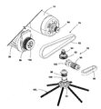
도 5는 브러시 롤 구동 커플링 및 모서리 청소 브러시 구동 커플링을 나타내기 위해 상부 커버 및 상부 기어 커버가 제거된 베이스의 일부분의 확대 사시도이다.
도 6은 도 5의 브러시 롤 구동 커플링 및 모서리 청소 브러시 드라이브 커플링의 분해도이다.
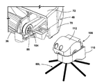
도 7은 도 6의 모서리 청소 브러시 구동 커플링 및 모서리 청소 브러시를 포함하는 모듈형 유닛을 나타내는 분해도이다.
도 8은 도 7의 모듈형 유닛을 보여주는 후면 사시도이다.
도 9는 도 XX의 라인 IX-IX를 통해 취한 단면도이며, 브러시 롤과 구동 가능하게 연결된 다른 모서리 청소 브러시를 도시한다.
도 10은 모서리 청소 브러시의 다른 실시예의 평면도이다.
도 11은 청소할 표면 상의 도 10의 모서리 청소 브러시의 사시도이며, 청소 도구에 하향 힘을 가하는 텐셔너 허브를 도시한다.
도 12는 도 10의 모서리 청소 브러시의 분해도이다.
도 13은 도 10의 모서리 청소 브러시용 텐셔너 허브의 사시도이다.
도 14는 도 10의 모서리 청소 브러시의 일부분의 확대 사시도이다.
도 15는 도 10의 모서리 청소 브러시의 일부분을 확대한 평면도이다.
도 16은 모서리 청소 브러시의 또 다른 실시예의 평면도이다.
도 17은 청소 도구에 하향 힘을 가하는 텐셔너 허브를 도시하는, 청소할 표면 상의 도 16의 모서리 청소 브러시의 사시도이다.
도 18은 청소 도구에 부착된 텐셔너 허브를 도시하기 위해 부착 허브가 제거 된, 도 16의 모서리 청소 브러시의 사시도이다.
도 19는 모서리 청소 브러시의 또 다른 실시예의 평면도이다.
도 20은 모서리 청소 브러시의 추가 실시예의 상부 사시도이다.
도 21은 도 20의 모서리 청소 브러시의 저면도이다.
도 22는 도 20의 모서리 청소 브러시의 분해도이다
도 23은 모서리 청소 브러시 용 텐셔너 허브의 또 다른 실시예의 상부 사시도이다.
도 24는 모서리 청소 브러시 용 텐셔너 허브 및 회전체의 또 다른 실시예의 상부 사시도이다.1 is a schematic diagram of a floor cleaner including one or more edge cleaning brushes in accordance with various aspects described herein;
FIG. 2 is a bottom view of the base of the floor cleaner of FIG. 1 ;
Fig. 3 is an enlarged view of the portion of Fig. 2 showing the edge cleaning brush on the underside of the base;
4 is a perspective view of the base with the top cover of the base and the top gear cover for the drive coupling of the edge cleaning brush disassembled to show the internal components of the base;
5 is an enlarged perspective view of a portion of the base with the top cover and top gear cover removed to show the brush roll drive coupling and the edge cleaning brush drive coupling;
FIG. 6 is an exploded view of the brush roll drive coupling and edge cleaning brush drive coupling of FIG. 5 ;
FIG. 7 is an exploded view illustrating the modular unit including the edge cleaning brush driving coupling and the edge cleaning brush of FIG. 6 ;
FIG. 8 is a rear perspective view showing the modular unit of FIG. 7 ;
Fig. 9 is a cross-sectional view taken through line IX-IX of Fig. XX, showing another edge cleaning brush drivably connected with the brush roll;
10 is a plan view of another embodiment of an edge cleaning brush;
11 is a perspective view of the edge cleaning brush of FIG. 10 on the surface to be cleaned, showing the tensioner hub applying a downward force to the cleaning tool;
12 is an exploded view of the edge cleaning brush of FIG. 10 .
13 is a perspective view of the tensioner hub for the edge cleaning brush of FIG. 10 .
14 is an enlarged perspective view of a portion of the edge cleaning brush of FIG. 10 ;
15 is an enlarged plan view of a portion of the edge cleaning brush of FIG. 10 .
16 is a plan view of another embodiment of an edge cleaning brush.
17 is a perspective view of the edge cleaning brush of FIG. 16 on a surface to be cleaned, showing the tensioner hub applying a downward force to the cleaning tool;
18 is a perspective view of the edge cleaning brush of FIG. 16 with the attachment hub removed to show the tensioner hub attached to the cleaning tool;
19 is a plan view of another embodiment of an edge cleaning brush;
20 is a top perspective view of a further embodiment of an edge cleaning brush;
Fig. 21 is a bottom view of the edge cleaning brush of Fig. 20;
Fig. 22 is an exploded view of the edge cleaning brush of Fig. 20;
23 is a top perspective view of another embodiment of a tensioner hub for an edge cleaning brush;
24 is a top perspective view of another embodiment of a tensioner hub and a rotating body for an edge cleaning brush;
본 개시물은 일반적으로 견목(hardwood), 타일 및 돌과 같은 맨 바닥 및 카펫 및 러그와 같은 부드러운 표면을 포함하는 저면을 청소하는 표면 청소 장치 용 브러시에 관한 것이다. 모서리 청소 브러시의 다양한 실시예가 아래에 설명된다. 본 명세서의 설명으로부터 이해되는 바와 같이, 모서리 청소 브러시는 여러 용도를 가질 수 있지만, 일반적으로 청소할 표면 위로 이동하도록 구성된 바닥 청소기의 하우징에 제공되며, 벽,베이스 보드, 캐비닛, 가구 등에 의해 만들어진 모서리 또는 모퉁이를 포함하여, 방의 모서리 및 모퉁이와 같이 잘 닿지 않는 공간을 청소할 수 있는 하우징 상의 위치에 배치된다. 본 명세서에 제공된 모서리 청소 브러시의 적어도 일부 실시예는 청소할 표면과 접촉하는 청소 도구에 하향 힘을 가하는 장력 요소를 갖는다. 또 다른 양태에서, 모서리 청소 브러시를 위한 구동 시스템이 아래에 설명된다.FIELD OF THE INVENTION The present disclosure relates generally to brushes for surface cleaning devices for cleaning undersides, including bare floors such as hardwood, tiles and stones, and soft surfaces such as carpets and rugs. Various embodiments of edge cleaning brushes are described below. As will be understood from the description herein, edge cleaning brushes may have several uses, but are generally provided in a housing of a floor cleaner configured to move over a surface to be cleaned, and may contain corners or edges made by walls, baseboards, cabinets, furniture, etc. It is placed in a location on the housing to clean hard-to-reach spaces such as corners and corners of rooms, including corners. At least some embodiments of the edge cleaning brushes provided herein have a tension element that applies a downward force to the cleaning tool in contact with the surface to be cleaned. In another aspect, a drive system for an edge cleaning brush is described below.
표면 청소 장치의 기능 시스템은 베이스를 갖는 직립형(upright) 장치 및 청소할 표면을 가로 질러 베이스를 보내는 직립형 본체와 같은 임의의 원하는 구성으로 배열될 수 있다. 다른 구성은 진공 호스에 의해 바퀴 달린 베이스에 연결된 청소 도구를 갖는 캐니스터 장치, 비교적 작은 영역을 청소하기 위해 사용자가 손에 들고 다닐 수 있는 휴대용 장치, 자율 또는 로봇 장치 또는 상용 장치를 포함한다. 전술한 임의의 청소기는 노즐과 흡입 소스 사이에 작업 공기 도관의 일부를 형성 할 수 있는 가요성 진공 호스를 포함하도록 구성될 수 있다. 임의의 앞서 언급한 청소기들은 무선 또는 유선 작동에 맞게 조정될 수 있으며, 선택사항으로서 무선 작동을 위한 온보드 배터리를 포함한다. The functional system of the surface cleaning device may be arranged in any desired configuration, such as an upright device with a base and an upright body that directs the base across the surface to be cleaned. Other configurations include a canister device with a cleaning tool connected to a wheeled base by a vacuum hose, a portable device that can be carried in the user's hand for cleaning a relatively small area, an autonomous or robotic device, or a commercial device. Any of the cleaners described above may be configured to include a flexible vacuum hose that may form part of a working air conduit between the nozzle and the suction source. Any of the aforementioned vacuums can be adapted for wireless or wired operation and optionally include an onboard battery for wireless operation.
일 실시예에서, 표면 청소 장치는 적어도, 바닥 표면에서 쓰레기를 흡입하고 추후 처리를 위해 장치에 제공된 공간에 제거된 쓰레기를 모으기 위해 부분 진공을 생성하는 진공 수집 시스템을 포함하는 진공 청소기일 수 있다. 용어 "쓰레기"는 달리 명시되지 않는 한 먼지, 티끌, 흙, 머리카락, 얼룩 및 기타 쓰레기를 포함한다.In one embodiment, the surface cleaning device may be a vacuum cleaner comprising at least a vacuum collection system that draws waste from the floor surface and creates a partial vacuum to collect the removed waste in a space provided to the device for further processing. The term "garbage" includes dust, dust, dirt, hair, stains and other garbage, unless otherwise specified.
다른 실시예에서, 표면 청소 장치는 흡입을 사용하지 않고 청소할 표면에서 마른 쓰레기를 제거하고 제거된 쓰레기를 추후 처리를 위해 장치에 제공된 공간에 모으는 스위핑 시스템을 포함하는 스위퍼일 수 있다.In another embodiment, the surface cleaning device may be a sweeper comprising a sweeping system that removes dry debris from a surface to be cleaned without the use of suction and collects the removed debris in a space provided in the device for further processing.
또 다른 실시예에서, 표면 청소 장치는 추출 청소기 또는 딥 청소기일 수 있으며, 청소 유체를 저장하고 청소 유체를 청소할 표면으로 전달하기 위한 유체 전달 시스템 및 청소할 표면으로부터 청소 유체 및 쓰레기를 제거하고 회수된 청소 유체 및 쓰레기를 저장하는 유체 회수 시스템을 포함할 수 있다. 유체 전달 시스템은 청소할 표면에 액체, 스팀, 분무 또는 증기를 전달하도록 구성될 수 있다.In another embodiment, the surface cleaning device may be an extractor or dip cleaner, and a fluid delivery system for storing and delivering cleaning fluid to the surface to be cleaned and removing cleaning fluid and debris from the surface to be cleaned and recovered cleaning It may include a fluid recovery system for storing fluid and waste. The fluid delivery system may be configured to deliver liquid, steam, spray or vapor to the surface to be cleaned.
또 다른 실시예에서, 표면 청소 장치는 청소 유체를 저장하고 청소 유체를 청소할 표면에 전달하기 위한 유체 전달 시스템 및 흡입을 사용하지 않고 청소할 표면으로부터 청소 유체 및 쓰레기를 제거하기 위한 모핑(mopping) 또는 스위핑 시스템을 포함하는, 습식 모핑 또는 스위핑 장치일 수 있다. 유체 전달 시스템은 청소할 표면에 액체, 스팀, 분무 또는 증기를 전달하도록 구성될 수 있다.In yet another embodiment, a surface cleaning device comprises a fluid delivery system for storing cleaning fluid and delivering the cleaning fluid to a surface to be cleaned and mopping or sweeping to remove cleaning fluid and debris from a surface to be cleaned without the use of suction. It may be a wet morphing or sweeping device, including a system. The fluid delivery system may be configured to deliver liquid, steam, spray or vapor to the surface to be cleaned.
도 1은 직립형 표면 청소 장치, 보다 구체적으로는 직립형 진공 청소기로 도시되고 일반적으로 10으로 표시되는 본 발명의 일 양태에 따른 표면 청소 장치의 일 부분의 사시도이다. 아래에서 더 상세히 논의되는 바와 같이, 진공 청소기(10)는 아래에서 더 상세히 설명되는 적어도 하나의 모서리 청소 브러시(60)를 포함하는 다양한 특징 및 개선을 포함한다. 적어도 하나의 모서리 청소 브러시(60)는 벽, 베이스 보드, 캐비닛, 가구 등에 의해 만들어진 모서리 또는 모퉁이를 포함하여 방의 모서리 및 모퉁이를 따라 잘 닿지 않는 공간을 청소할 수 있다. 본 명세서에 도시된 바와 같이, 진공 청소기(10)는 직립형 핸들 어셈블리 또는 본체(12) 및 직립형 본체(12)에 장착되거나 결합되고 청소할 표면을 가로 질러 이동하도록 구성된 청소 풋 또는 베이스(14)를 포함하는 하우징을 갖는다. 진공 청소기(10)는 아래에서 더 자세히 설명되어 있고 본체(12) 및 베이스(14) 중 하나 또는 이 둘 모두에서 지지되는 구성요소를 포함할 수 있는 진공 수집 시스템을 포함한다. 1 is a perspective view of a portion of a surface cleaning apparatus in accordance with an aspect of the present invention, shown as an upright surface cleaning apparatus, more particularly as an upright vacuum cleaner, and generally indicated at 10; As discussed in greater detail below,
도면과 관련 지은 설명의 목적으로, 용어 "상", "하", "좌", "우", "후", "전", "수직", "수평" 및 "내부", "외부" 및 이들의 파생어는 진공 청소기(10)의 후방을 형성하는 진공 청소기(10) 뒤의 사용자의 관점에서 도 1에 배향된 본 개시물과 관련될 것이다. 그러나, 분명히 다르게 명시된 경우를 제외하고는 본 개시 내용이 다양한 대안적인 배향을 가정할 수 있음을 이해해야 한다.For purposes of description and reference to the drawings, the terms “top”, “bottom”, “left”, “right”, “after”, “front”, “vertical”, “horizontal” and “inside”, “outside” and Their derivatives will relate to the present disclosure oriented in FIG. 1 from the perspective of a user behind the
직립형 본체(12)는 본 명세서에 설명된 목적에 적합한 임의의 유형의 긴 핸들 또는 본체를 포함할 수 있으며, 핸들을 포함할 수도 있고 또는 사용자가 청소할 표면 위로 진공 청소기(10)를 조작할 수 있도록 다르게 구성될 수 있다. 직립형 본체(12)는 청소할 표면에 대해 일정 범위의 각도를 통해 하나 이상의 축을 중심으로 피벗하도록 구성될 수 있다. 선택사항으로서, 직립형 본체(12)는 베이스(14)에 대한 피봇팅에 추가하여 그것의 종방향 축을 중심으로 회전(swivel)하도록 구성될 수 있다.The
도 2를 더 참조하면, 진공 수집 시스템은 본체(12) 및 베이스(14) 중 하나 또는 이 둘 모두를 포함하는 하우징을 통한 작업 공기 경로 또는 회수 경로를 포함할 수 있다. 회수 경로는 적어도 오물 유입구(16) 및 클린 에어 배출구(18)를 포함할 수 있다. 이 경로는 다른 요소들 중에서 오물 유입구를 형성하는 흡입 노즐(20), 작업 공기 스트림을 생성하기 위해 흡입 노즐(20)과 유체 연통하는 흡입 소스(22), 추후 처리를 위해 작업 공기 스트림으로부터 쓰레기를 모으기 위한 쓰레기 수집기(24) 및 클린 에어 배출구(18)를 형성하는 적어도 하나의 배기구(26)로 형성될 수 있다. With further reference to FIG. 2 , the vacuum collection system may include a return path or a working air path through a housing that includes one or both of
진공 모터(28) 및 팬(30)을 포함하는 모터/팬 어셈블리일 수 있는 흡입 소스(22)는 수집기(24)와 유체 연통하도록 제공된다. 모터/팬 어셈블리(22)는 공기 배출구의 상류에 유동적으로(fluidly) 있을 수 있고 작업 공기 경로의 일부를 형성할 수 있다. 모터/팬 어셈블리(22)는 회수 경로에서 수집기(24)의 하류에 배치될 수 있다. 다른 실시예에서, 모터/팬 어셈블리(22)는 수집기(24)의 상류에 유동적으로 위치할 수 있다.A
수집기(24)는 또한 작업 공기 경로의 일부를 형성할 수 있고 작업 공기 흐름으로부터 쓰레기를 분리하기 위한 분리기(도시되지 않음)를 포함할 수 있다. 분리기의 몇몇 비제한적인 예는 적어도 하나의 사이클론 또는 원심 분리기, 필터 스크린, 폼 필터, HEPA 필터, 가요성 및 통기성 필터 백, 또는 이들의 조합을 포함한다.
수집 시스템은 흡입 소스(22)의 상류 또는 하류에 하나 이상의 추가 필터를 포함할 수 있다. 예를 들어, 도시된 실시예에서, 전-모터 필터(32)가 수집기의 하류 및 흡입 소스(22)의 상류에서 회수 경로에 제공된다. 후-모터 필터(34)는 흡입 소스(22)의 하류 및 클린 에어 배출구(18)의 상류의 회수 경로에 제공될 수 있다. 수집 시스템은 진공 수집 시스템의 다양한 구성요소 사이의 유체 연통을 위한 다양한 도관, 덕트 또는 튜브를 추가로 포함할 수 있다. The collection system may include one or more additional filters upstream or downstream of the
도 2를 참조하면, 흡입 노즐(20)은 베이스(14) 상에 제공될 수 있으며, 베이스(14)가 표면을 가로 질러 이동할 때 청소할 표면에 인접하도록 구성될 수 있다. 브러시 롤(36) 또는 다른 교반기가 흡입 노즐(20)에 인접하게 제공되어 쓰레기가 흡입 노즐(20) 내로 더 쉽게 흡입되도록 청소할 표면을 교반할 수 있다. 여기 도시된 흡입 노즐(20)은 표면으로부터 쓰레기를 제거하기 위해 청소할 표면과 마주하도록 배치된다. 다른 실시예에서, 흡입 노즐(20)은 브러시 롤(36)로부터 직접 쓰레기를 수집하기 위해 브러시 롤(36)에 매우 근접하게 배치될 수 있다.Referring to FIG. 2 , the
여기에 도시된 60L, 60R 실시예에서, 흡입 노즐(20)은 2 개의 모서리 청소 브러시(60L, 60R) 사이에 제공된다. 다른 실시예에서, 흡입 노즐(20)은 모서리 청소 브러시(60L, 60R)의 후방에 제공될 수 있다. 어떤 경우든, 모서리 청소 브러시(60L, 60R)는 베이스(14) 아래의 쓰레기를 흡입 노즐(20)을 향해 쓸어낼 수 있다.In the 60L, 60R embodiment shown here, a
진공 청소기(10)는 브러시 롤(36)이 장착되는 브러시 챔버(38)를 포함할 수 있다. 브러시 롤(36)은 베이스(14)가 이동하는 표면에 대해 실질적으로 수평축(X)을 중심으로 회전하도록 장착된다. 흡입 노즐(20)은 브러시 챔버(38)의 하면에 형성될 수 있다. 모서리 청소 브러시(60L, 60R)는 브러시 챔버(38)의 측면 또는 단부의 바깥쪽에 위치할 수 있다.The
본 예에서, 브러시 롤(36)은 강모 없는 브러시 롤 또는 롤러일 수 있다. 도 2에 도시된 브러시 롤(36)은 코어(42) 및 코어(42)로부터 연장되는 복수의 셰브론 베인(chevron vane)(44)을 포함하지만, 다양한 다른 베인 형상이 사용될 수 있다. 베인(44)은, 예컨대, 주입 몰딩, 적층 제조(additive manufacturing) 또는 다른 적절한 공정을 통해 코어(42)와 일체로 형성될 수 있다. 코어(42) 및 베인(44)은 아크릴로니트릴 부타디엔 스티렌(ABS), 폴리 프로필렌 또는 스티렌과 같은 중합체 재료, 또는 플라스틱, 목재 또는 금속과 같은 임의의 다른 적합한 재료로 구성될 수 있다.In this example,
브러시 롤(36)의 다른 실시예가 가능하다. 예를 들어, 브러시 롤(36)은 술을 갖는(tufted) 강모 또는 극세사와 같은 부드럽고 압축 가능한 재료를 포함할 수 있다. 또 다른 실시예에서, 브러시 롤(36)은 나일론 섬유, 폼(foam), 엘라스토머 블레이드 및 패들을 포함할 수 있다. 추가로, 단일 수평 회전 브러시 롤(36)이 여기에 도시되어 있지만, 일부 실시예에서, 이중 수평 회전 브러시 롤이 진공 청소기(10)에 제공될 수도 있다.Other embodiments of
다른 실시예에서, 브러시 롤(36)은 경질 및 연질 표면 모두에 사용하기에 적합하고 습식 또는 건식 진공 청소에 적합한 하이브리드 브러시 롤일 수 있다. 이러한 하이브리드 브러시 롤은 강모 및 극세사 조합을 포함할 수 있다. 적합한 하이브리드 브러시 롤의 한 예는 2018 년 10 월 9 일에 발행된 미국 특허 제10,092,155 호에 개시되어 있으며, 이는 그 전체가 본 명세서에 참조로 포함된다.In other embodiments,
흡입 노즐(20)은 도관(46)을 통해 수집기(24)와 유체 연통할 수 있다. 수집기(24)가 직립형 본체(12) 상에 위치하는 실시예에서, 도관(46)은 베이스(14)와 직립형 본체(12) 사이의 조인트 어셈블리를 통과할 수 있고, 베이스(14)에 대한 직립형 본체(12)의 움직임을 수용하도록 유연할 수 있다. The
베이스(14)는 본 명세서에 도시된 실시예에서 브러시 롤(36) 및 모서리 청소 브러시(60L, 60R)와 같은, 수집 시스템의 구성요소 중 적어도 일부를 지지하는 베이스 하우징(48)을 포함할 수 있다. 한 쌍의 휠(50)은 청소할 표면 위로 진공 청소기(10)를 이동시키기 위해 베이스 하우징(48)에 부착될 수 있다. 휠(50)은 베이스 하우징(48)의 후방 부분에, 흡입 노즐(20), 브러시 롤(36), 모서리 청소 브러시(60L, 60R) 또는 이들의 임의의 조합과 같은 구성요소의 후방에 제공될 수 있다. 제2 쌍의 휠(52)은 제1 쌍의 휠(50)의 전방에서 베이스 하우징(48)에 부착될 수 있다.
도시된 진공 청소기(10)는 베이스(14)의 밑면(54)에, 예를 들어, 베이스 하우징(48)의 밑면에 2 개의 모서리 청소 브러시(60L, 60R)를 포함한다. 모서리 청소 브러시(60L, 60R)는 베이스(14)가 이동하는 표면에 대해 각각 실질적으로 수직인 회전축(V1, V2)을 중심으로 회전하도록 장착된다. 실질적으로 수직인 경우, 회전축(V1, V2)은 수직에서 최대 5도, 수직에서 최대 10도, 수직에서 최대 20도, 또는 수직에서 최대 45도 벗어날 수 있다. 일부 실시예에서, 회전축(V1, V2)은 모서리 청소 브러시(60L, 60R)와 청소할 표면 사이의 접촉 면적을 최대화하도록 구성된다. 본 실시예에서는, 2 개의 모서리 청소 브러시(60L, 60R)가 제공되고, 베이스(14)의 양측, 즉, 좌우 측에 배치되어 진공 청소기(10)가 베이스(14)의 방향을 변경하지 않고 베이스(14)의 양측에서 모서리 청소를 할 수 있도록 한다. 다른 실시예에서, 단지 하나의 모서리 청소 브러시(60)가 제공된다.The illustrated
유리하게는, 모서리 청소 브러시(60L, 60R)는 베이스(14) 아래의 쓰레기를 흡입 노즐(20)을 향해 쓸어 낸다. 각 모서리 청소 브러시(60L, 60R)에 대한 회전 방향은 화살표(R1 및 R2)로 도 3에 표시되어 있다. 도 2에 도시된 바와 같이, 모서리 청소 브러시(60L, 60R)는 양쪽 브러시(60L, 60R)에 의해 쓰레기가 흡입 노즐(20)을 향해 쓸려지도록 역회전할 수 있고, 흡입 소스(22)는 쓰레기를 수집기(24)로 운반할 수 있다. 좌측 모서리 청소 브러시(60L)는 아래에서 볼 때 시계 방향(R1)으로 회전한다. 우측 모서리 청소 브러시(60R)는 아래에서 볼 때 반 시계 방향(R2)으로 회전한다. 일 예에서, 모서리 청소 브러시(60L, 60R 60)의 적어도 일부분은 진공 청소기(10)의 베이스(14)에 인접한 쓰레기가 흡입 노즐(20)을 향해 쓸려질 수 있도록 베이스 하우징(48)의 둘레부를 넘어 연장된다. 본 명세서에 도시된 실시예에서, 모서리 청소 브러시(60L, 60R)는 베이스(14)의 전방 또는 선단(56), 흡입 노즐(20)의 전방에 장착되고, 베이스(14)의 중앙 및 후방을 향해, 즉, 흡입 노즐(20)을 향해 쓰레기를 쓸어낸다. 모서리 청소 브러시(60L, 60R)는 또한 브러시 롤(36)의 축(X)의 전방으로 장착되고, 쓰레기를 수집하는 것을 도울 수 있는 브러시 롤(36)을 향해 쓰레기를 쓸어 낸다. 다른 실시예에서, 모서리 청소 브러시(60L, 60R)는 베이스(14)의 다른 위치에, 베이스(14)의 좌측면을 따라, 또는 베이스(14)의 우측면을 따라 장착될 수 있다.Advantageously, the edge cleaning brushes 60L, 60R sweep the debris under the base 14 towards the
장치(10)의 다른 실시예에서, 수집 시스템은, 예컨대, 기계적으로 쓰레기를 수집기(24)로 직접 보내는 브러시 롤(36) 및 모서리 청소 브러시(60L, 60R)의 작용에 의해 흡입을 사용하지 않고 쓰레기 및 액체를 기계적으로 수집하는 스위핑 또는 기계 수집 시스템으로서 구성될 수 있다. 이러한 실시예에서, 모서리 청소 브러시(60L, 60R)는 베이스(14) 아래에서 그리고 베이스(14)상의 쓰레기 유입구를 향해 쓰레기를 쓸어낼 수 있다.In another embodiment of
또 다른 대안적인 또는 추가적인 수집 메커니즘에서, 장치(10)는 청소할 표면으로부터 젖은 쓰레기를 제거하기 위한 모핑 또는 더스팅(dusting) 어셈블리를 포함할 수 있다. 이러한 모핑 또는 더스팅 어셈블리는 선택사항으로서 적어도 하나의 모핑 또는 더스팅 패드 및 베이스(14) 아래에서 그리고 패드 쪽으로 쓰레기를 쓸어 낼 수 있는 하나 이상의 모서리 청소 브러시(60L, 60R)를 포함할 수 있다. 패드는 고정될 수도 있고, 또는 회전 가능할 수도 있다.In yet another alternative or additional collection mechanism, the
모서리 청소 브러시(60L, 60R)는 청소할 표면에서 쓰레기를 솔질, 쓸기, 먼지 제거, 걸레질 또는 다른 방식으로 이동시키도록 구성된 하나 이상의 상이한 교반 또는 청소 도구를 포함할 수 있다. 모서리 청소 브러시(60L, 60R)를 위한 청소 도구의 일부 비 제한적인 예는 블레이드, 강모, 패들, 블레이드, 플랩, 극세사 재료, 직물, 더스팅 패드 등을 포함한다.Edge cleaning brushes 60L, 60R may include one or more different agitation or cleaning tools configured to brush, sweep, dust, mop or otherwise displace debris from the surface to be cleaned. Some non-limiting examples of cleaning tools for edge cleaning brushes 60L, 60R include blades, bristles, paddles, blades, flaps, microfiber materials, fabrics, dusting pads, and the like.
도 3에 도시된 모서리 청소 브러시(60L)의 실시예는 베이스 하우징(48)에 대해 회전하도록 구성된 회전체(62) 및 함께 회전하기 위해 회전체(62)와 결합된 청소 도구(64)를 포함한다. 회전체(62)와 "결합"됨으로써, 청소 도구(64)는 함께 회전하도록 회전체(62)에 부착되거나, 형성되거나, 다른 방식으로 적절하게 접합(joint)될 수 있다. 청소 도구(64)는 청소할 표면상의 쓰레기를 솔질, 쓸기, 먼지 제거, 걸레질 또는 다른 방식으로 이동시키도록 구성될 수 있다. 전술한 바와 같이, 청소 도구(64)는 청소할 표면 상의 쓰레기를 흡입 노즐(20) 또는 하우징(48)상의 다른 쓰레기 유입구 쪽으로 이동시킬 수 있다.The embodiment of the
청소 도구(64)는 복수의 강모 세트(66)를 포함할 수 있으며, 각각의 강모 세트(66)는 복수의 강모를 포함한다. 이 강모는 나일론, 폴리부틸렌 테레프탈레이트(PBT), 또는 임의의 다른 적합한 합성 또는 천연 섬유로 구성될 수 있다. 강모 세트(66)는 도시된 바와 같이 회전체(62)로부터 반사항으로 돌출될 수도 있고, 또는 다른 실시예에서 접선 방향으로 또는 다른 각도로 돌출될 수도 있다.The
청소 도구(64)의 일부는 베이스(14)의 전방 또는 선단(56)을 넘어 돌출할 수 있고 및/또는 베이스(14)의 측면(68)을 넘어 돌출할 수도 있다. 예를 들어, 강모 세트(66)의 일부의 원위 단부는 베이스 하우징(48)의 전방 및 측방을 포함하여 도 3에 도시된 바와 같이 베이스 하우징(48) 외부로 연장될 수 있다.A portion of the
강모 세트(66)의 길이는 도시된 바와 같이 서로 동일할 수도 있고, 또는 상이한 길이의 강모 세트가 제공될 수도 있다. 또한, 각 세트(66) 내의 강모가 동일한 길이를 갖는 것으로 도시되어 있지만, 모서리 청소 브러시(60L)의 다른 실시예에서, 하나의 세트(66) 내의 개별 강모의 길이가 다양할 수 있다는 점에 유의해야 한다. The lengths of the sets of
강모 세트(66)는 회전축(V1)에 대해 동일하게 이격될 수 있다. 예를 들어, 도시된 모서리 청소 브러시(60L)의 실시예에서, 청소 도구(64)는 서로 약 60 ° 이격된 6 개의 강모 세트(66)를 포함할 수 있다. 제한하지 않는 예로서, 서로 약 40° 이격된 9 개의 강모 세트 (66)와 같이, 다른 강모 세트의 개수 및 간격도 가능하다. 또 다른 실시예에서, 별개의 세트로 배열되는 것이 아니라, 강모는 회전체(62) 주위에 실질적으로 연속적으로 배열될 수도 있다.The set of
회전체(62)는 회전축(V1)상에서 회전하도록 구성된 허브를 포함할 수 있다. 선택사항으로서, 회전체(62)는 회전축(V1)으로부터 반사상 외측으로 배치 된 둘레 표면을 포함할 수 있고, 강모 세트(66)는 둘레면에 대해 반사상으로 돌출할 수 있다. 다른 실시예에서, 강모 세트(66)는 둘레면으로부터 접선 방향으로 또는 다른 각도로 돌출할 수 있다.The rotating
도 4를 참조하면, 베이스 하우징(48)은 하나 이상의 개별 부품, 케이싱 또는 하우징으로 구성될 수 있다. 비 제한적인 일 예에서, 베이스 하우징(48)은 적어도 그 사이에 베이스(14)의 구성요소를 둘러싸는 상부 커버(72) 및 하부 커버(70)를 포함할 수 있다. 상부 커버(72)는 도 4에서 하부 커버(70)로부터 분해된 것으로 도시되어 있다. Referring to FIG. 4 , the
일 실시예에서, 브러시 롤(36) 및 양쪽 모서리 청소 브러시(60L, 60R)는 베이스(14) 내에 브러시 롤 모터 또는 브러시 모터(74)를 포함하는 구동 어셈블리에 작동 가능하게 결합되고 구동 어셈블리에 의해 구동될 수 있다. 대안으로서, 진공 모터(28)(도 3)는 진공 흡입을 제공하고 브러시(36, 60L, 60R) 중 하나 이상을 회전시킬 수 있다. 다른 대안의 실시예에서, 브러시 모터(74)로부터 분리된 모터(도시되지 않음)는 모서리 청소 브러시(60L, 60R)를 구동하기 위해 베이스(14)에 제공될 수 있으며, 양쪽 모서리 청소 브러시(60L, 60R)는 공통의 별도 모터에 작동 가능하게 결합되고 별도 모터에 의해 구동된다. 또 다른 대안의 실시예에서, 브러시 모터(74)로부터 분리된 개별 모터(도시되지 않음)는 각각의 모서리 청소 브러시(60L, 60R)를 구동하기 위해 베이스(15)에 제공 될 수 있으며, 각각의 모서리 청소 브러시(60L, 60R)는 개별적인 별도 모터 중 하나에 작동 가능하게 결합되고 그것에 의해 구동된다. In one embodiment,
도시된 실시예에서, 브러시 모터(74)는 회전축(X)을 중심으로 브러시 롤(36)을 구동시키고, 회전축(V1)을 중심으로 제1 또는 좌측 모서리 청소 브러시(60L)를 구동시키고, 그리고 회전축(V2)을 중심으로 제2 또는 우측 모서리 청소 브러시(60R)를 구동시키도록 구성된다. 구동 커플링 또는 변속기는 브러시 모터(74)를 각각의 브러시(36, 60L, 60R)에 연결한다. 각 구동 커플링은 하나 이상의 벨트, 기어, 샤프트, 풀리 또는 이들의 조합을 포함할 수 있다.In the illustrated embodiment, the
모서리 청소 브러시(60L, 60R)의 회전축(V1, V2)은 브러시 롤(36)의 양 단부에 배치될 수 있다. 도시된 실시예에서, 모서리 청소 브러시(60L, 60R)의 회전축(V1, V2)은 브러시 롤(36)의 각 단부로부터 이격된다. 도 2의 저면도에 도시된 바와 같이, 모서리 청소 브러시(60L, 60R)의 회전축(V1, V2)은 회전축(X)의 전방에 배치될 수 있다. 다른 실시예에서, 회전축(V1, V2)은 회전축(X)과 교차할 수 있다.The rotation shafts V1 and V2 of the edge cleaning brushes 60L and 60R may be disposed at both ends of the
모서리 청소 브러시(60L, 60R)의 회전축(V1, V2)은 브러시 롤(36)의 회전축(X)에 실질적으로 수직일 수 있다. 실질적으로 수직인 경우, 회전축(V1, V2)은 수직에서 최대 5도, 수직에서 최대 10도, 또는 수직에서 최대 20도 벗어날 수 있다. 모서리 청소 브러시(60L, 60R)의 회전축(V1, V2)은 서로 평행할 수도 있고, 또는 평행하지 않을 수도 있다.The rotation axes V1 and V2 of the edge cleaning brushes 60L and 60R may be substantially perpendicular to the rotation axis X of the
도 4에 도시된 실시예에서, 브러시 롤(36)은 브러시 모터(74), 및 브러시 롤(36)과 브러시 모터(74) 사이의 구동 커플링 또는 변속기(76)를 포함하는 구동 어셈블리에 작동 가능하게 결합되고 구동 어셈블리에 의해 구동된다. 제1 모서리 청소 브러시(60L)는 브러시 모터(74), 및 브러시(60L)와 브러시 롤(36) 사이의 구동 커플링 또는 변속기(78)를 포함하는 구동 어셈블리에 작동 가능하게 결합되고 구동 어셈블리에 의해 구동된다. 제2 모서리 청소 브러시(60R)는 브러시 모터(74), 및 브러시(60R)와 브러시 롤(36) 사이의 구동 커플링 또는 변속기(80)를 포함하는 구동 어셈블리에 작동 가능하게 결합되고 구동 어셈블리에 의해 구동된다. In the embodiment shown in FIG. 4 ,
각각의 모서리 청소 브러시(60R, 60L)에 대한 모서리 브러시 구동 커플링(78, 80)은 브러시(60R, 60L)의 구동 속도를 감소시키도록 구성되어, 모서리 청소 브러시(60R, 60L)가 브러시 롤(36)보다 느린 속도로 움직인다. 감소되지 않으면, 모서리 청소 브러시(60R, 60L)는 쓰레기를 흡입 노즐(20)을 향해 쓸어내는 대신 베이스(14)로부터 쓰레기를 튕겨낼 수 있다. 하나의 예에서, 브러시 롤(36)은 3000rpm, 대안적으로 3400rpm, 대안적으로 포괄적으로 3000-4375rpm, 대안적으로 포괄적으로 3100-3700rpm으로 구동되고, 모서리 청소 브러시(60R, 60L)은 110rpm, 대안적으로 135rpm, 대안적으로 포괄적으로 120-140rpm, 대안적으로 포괄적으로 150-175rpm으로 구동된다. The edge
도 5-6을 참조하면, 일 실시예에서 브러시 롤 구동 커플링(76)은 브러시 모터(74)의 출력에 결합된 구동 휠(84) 및 브러시 롤(36) 상의 구동 휠(86)과 마찰 결합되는 구동 벨트(82)를 포함할 수 있고, 이는 모터(28)에 의해 제공된 회전력을 브러시 롤(36)로 전달한다.5-6 , in one embodiment brush
모서리 브러시 드라이브 커플링(78)은 브러시 롤(36)과 결합되거나 브러시 롤(36)과 브러시 모터(74) 사이의 변속기와 결합된 입력 기어를 갖는 기어 트레인을 포함할 수 있다. 도 5-6에 도시된 실시예에서, 제1 모서리 청소 브러시(60L) 용 기어 트레인은 함께 회전하도록 브러시 롤(36)에 작동 가능하게 결합된 웜(90), 웜(90)에 맞물린 제1 또는 웜 기어(92) 및 함께 회전하도록 제1 기어(92)와 결합된 제2 기어(94)를 갖는 2단 종동 기어, 2단 기어의 회전력을 종동 기어(98)에 전달하기 위해 제2 기어(94)와 결합된 모서리 브러시 벨트(96)를 포함한다. 종동 기어(98)는 축(V1)을 중심으로 회전하도록 브러시(60L)를 구동하기 위해 모서리 청소 브러시(60L)와 결합된다.The edge
종동 기어(98)는 모서리 청소 브러시(60L)의 구동 샤프트(100)와 결합될 수 있다. 종동 기어(98)는 구동 샤프트(100)에 구동력을 출력하고 미리 정해진 속도로 회전한다. 구동 샤프트(100)는 모서리 청소 브러시(60L)의 회전축(V1)을 형성할 수 있다. 선택사항으로서, 구동 샤프트(100)는 모서리 청소 브러시(60L)의 회전체(62)(도 3)와 접합될 수도 있고, 또는 다른 방식으로 결합될 수 있다. 모서리 청소 브러시(60L)는 구동 샤프트(100)에 고정식으로 또는 제거 가능하게 장착될 수 있다. 제거 가능하게 장착된 경우, 모서리 청소 브러시(60L)는 진공 청소기 및 기타 바닥 청소 장치의 기존의 모서리 청소 브러시에 대한 애프터 마켓 또는 교체 부품이 될 수 있다.The driven
도 5-6과 관련하여 설명된 기어 트레인은 브러시 롤에 대한 모서리 청소 브러시(60L)의 회전 속도를 감소시킬 수 있다. 일 실시예에서, 웜(90)으로부터 종동 기어(98)로의 기어 감속비는 1:30 일 수 있다.The gear train described with respect to FIGS. 5-6 may reduce the rotational speed of the
기어 트레인은 웜 기어(90)를 구동하기 위해 브러시 롤(36)의 종동 휠(86)과 결합될 수 있다. 도 6에 도시된 실시예에서, 스플라인 종동 부재(102)는 웜(90)과 결합되고, 브러시 롤(36)의 구동 휠(86)은 스플라인 종동 부재(102)와 축 방향으로 결합하도록 구성된 스플라인 구동 부재(104)를 포함할 수 있다. 스플라인 부재(102, 104)는 스플라인 부재(102, 104)가 축 방향으로 결합될 때 맞물리는 톱니, 쐐기 또는 다른 형상 부재를 갖는다. 따라서, 스플라인 부재(102, 104)는 토크를 웜(90)에 전달하기 위해 웜(90)과 종동 휠(86) 사이에 스플라인 연결을 형성한다. 브러시 롤(36)과 기어 트레인 사이의 다른 커플링도 가능하다.The gear train may engage the driven
도 5-6과 관련하여 설명된 기어 트레인 구성은 베이스(14)의 전면의 공간을 절약할 수 있으며, 모서리 청소 브러시(60L)의 회전축(V1)이 베이스(14)의 전단(56)에 더 가까워 지도록 한다. 웜 기어(90)를 통해 브러시(60L)를 직접 구동하는 대신에, 웜 기어(90)를 통해 브러시(60L)를 간접적으로 구동하기 위해 벨트(96)를 사용하면, 회전축(V1)이 브러시 롤 회전축(X)으로부터 더 멀리 배치되는 것을 가능하게 해준다. 대안의 실시예에서, 웜(90)은 구동 샤프트(100)에 부착 된 종동 기어(98)와 직접 결합되고, 벨트(96) 및 다른 기어(92, 94)에는 제공되지 않는다.The gear train configuration described with reference to FIGS. 5-6 can save space on the front side of the
기어 트레인이 웜 기어(90)를 구동하기 위해 브러시 롤(36)의 비구동 단부에서 스플라인 구동 부재(114)와 결합될 수 있다는 점을 제외하면, 다른 모서리 청소 브러시(60R)를 위한 모서리 브러시 구동 커플링(80)은 실질적으로 유사할 수 있다. 도 9에 도시된 실시예에서, 웜(90)과 결합된 스플라인 구동 부재(102)는 웜(90)에 토크를 전달하기 위해 스플라인 구동 부재(114)와 맞물릴 수 있다. 브러시 롤(36)과 기어 트레인 사이의 다른 커플링도 가능하다.Edge brush drive for another
도 7을 추가로 참조하면, 모서리 브러시 구동 커플링(78)은 베이스 하우징(48) 내에 수용될 수도 있고, 또는 하우징(48)과 함께 형성되거나 그렇지 않으면 하우징(48)에 결합되는 별도의 기어 케이싱(106) 내에 수용될 수도 있다. 소음 및 진동을 개선하기 위해, 구동 커플링(78)의 기어 트레인은 보다 정확한 허용공차를 갖는 모듈로서 기어 케이싱(106) 내에 위치할 수 있다. 기어 케이싱(106)은 구동 샤프트(100)가 연장되어 구동 커플링(78)을 모서리 청소 브러시(60)와 연결하는 개구(108)를 포함할 수 있다. 모서리 청소 브러시(60L) 용 기어 박스, 즉, 기어 구동 커플링(78) 및 그것의 케이싱(106)은 베이스 하우징(48)의 내부 또는 외부에 배치될 수도 있고, 베이스(14)로부터 제거될 수 있다. 제거 불가능한 기어 박스의 경우, 청소 도구와 같은 모서리 청소 브러시(60L)의 일부는 구동축(100)에 고정식으로 또는 제거 가능하게 장착될 수 있다.With further reference to FIG. 7 , the edge
기어 케이싱(106)은 하나 이상의 개별 부품, 케이싱 또는 하우징으로 구성 될 수 있다. 비 제한적인 일 예에서, 기어 케이싱(106)은 적어도 그 사이에서 모서리 브러시 구동 커플링(78)의 구성요소를 둘러싸는 하부 기어 하우징(110) 및 상부 기어 커버(112)를 포함할 수 있다. 기어 상부 커버(112)는 도 7에서 기어 하우징(110)으로부터 분해된 것으로 도시된다.
일 실시예에서, 모서리 브러시 구동 커플링(78), 기어 케이싱(106)을 포함하고, 그리고 선택사항으로서 또한 모서리 청소 브러시(60L)를 포함하는 모듈형 유닛이 베이스(14)에 제거 가능하게 장착된다. 도 7-8에 도시된 모듈형 유닛의 경우, 모서리 브러시 구동 커플링(78) 및 모서리 청소 브러시(60L)는 진공 청소기(10)와의 용이한 조립을 위해 기어 케이싱(106)을 베이스(14)에 부착함으로써 베이스(14)에 동시에 장착될 수 있다. 마찬가지로, 모서리 브러시 구동 커플링(78) 및 모서리 청소 브러시(60L)는 베이스(14)로부터 기어 케이싱(106)을 제거함으로써 베이스(14)로부터 동시에 제거 가능하며, 이는 모듈형 유닛 또는 모듈형 유닛의 구성요소를 청소, 수리 또는 교체하는 것을 가능하게 해준다. 모듈형 유닛 또는 기어 박스를 통해, 모서리 청소 브러시(60L)는 진공 청소기 및 기타 바닥 청소 장치의 기존 모서리 청소 브러시에 대한 애프터 마켓 또는 교체 부품이 될 수 있다. 모듈형 유닛이 도 5-6과 관련하여 설명된 모서리 브러시 구동 커플링(78)을 포함하는 것으로 도시되어 있지만, 다른 모서리 브러시 트랜스미션도 가능하다는 것이 이해될 것이다. In one embodiment, a modular unit including a corner
베이스(14)와 함께 모듈형 유닛 또는 기어 박스를 조립하기 위해, 기어 케이싱(106)은 하부 커버(70)와 조립될 수 있으며, 스플라인 부재(102, 104)가 결합되어 구동 커플링(78)을 브러시 롤(36)의 종동 휠(86)과 결합시킨다. 기어 케이싱(106)은 나사 또는 다른 패스너를 사용하여 하부 커버(70)에 기어 케이싱(106)을 장착하는 것과 같은 임의의 적절한 부착 방법을 사용하여 하부 커버(70)에 부착될 수 있다. 기어 케이싱(106)의 고정 후, 상부 커버(72)(도 4)는 하부 커버(70)에 장착될 수 있다. 상부 커버(72)는 도 1에 도시된 바와 같이 기어 케이싱(106)의 적어도 일부를 덮을 수 있다. To assemble a modular unit or gearbox with
도 4 및 도 9에 도시된 바와 같이, 우측 모서리 브러시 구동 커플링(80)을 위한 유사한 기어 케이싱(106)이 제공될 수 있다. 브러시 롤(36) 및 브러시 챔버(38)는 2 개의 기어 케이싱(106) 사이에 배치될 수 있다. 상부 커버(72)는 하부 커버(70)에 설치될 때 양 기어 케이싱(106)의 적어도 일부를 덮을 수 있다.4 and 9, a
도 10-15는 일반적으로 160으로 표시된 모서리 청소 브러시의 다른 실시예의 세부 사항을 보여준다. 모서리 청소 브러시(160)는 모서리 청소 브러시(60L, 60R) 중 하나 또는 둘 모두를 대신하여 도 1-9에 도시된 진공 청소기(10) 상에 제공될 수 있고, 또는 벽, 베이스 보드, 캐비닛, 가구 등에 의해 만들어진 모서리 또는 모퉁이를 포함하여 방의 모서리 및 모퉁이를 따라 잘 닿지 않는 공간을 청소하기 위해 다른 표면 청소 장치 상에 제공될 수도 있다. 모서리 청소 브러시(160)는 실질적으로 수직인 회전축(V)을 중심으로 회전하도록 구성될 수 있다.10-15 show details of another embodiment of an edge cleaning brush, generally designated 160 . The
모서리 청소 브러시(160)는 베이스 하우징(48)(도 1) 또는 다른 바닥 청소기 하우징에 대해 회전하도록 구성된 회전체(162), 및 함께 회전하도록 회전체(162)와 결합된 청소 도구(164)를 포함할 수 있다. 회전체(162)와 "결합"됨으로써, 청소 도구(164)는 함께 회전하도록 회전체(162)에 부착되거나, 형성되거나, 다른 방식으로 적절하게 접합될 수 있다. 청소 도구(164)는 청소할 표면 상의 쓰레기를 솔질, 쓸기, 먼지제거, 걸레질 또는 다른 방식으로 이동시키도록 구성될 수 있다. 앞서 논의한 바와 같이, 청소 도구(164)는 청소할 표면상의 쓰레기를 흡입 노즐(20)(도 2) 또는 바닥 청소기상의 다른 쓰레기 유입구 쪽으로 이동시킬 수 있다. The
모서리 청소 브러시(160)는 청소할 표면(S)에 닿도록 청소 도구(164)를 강제하기 위해 청소 도구(164)에 하향 힘(F)(도 11 참조)를 가하는 텐셔너 허브(166)와 같은 장력 요소를 포함할 수 있다. 텐셔너 허브(166)는 또한 구조적 지지를 제공하여, 텐셔너 허브(166)를 사용하지 않을 경우에 흡입 노즐(20)(도 2) 또는 다른 쓰레기 유입구를 향해 청소할 표면 상의 쓰레기를 효과적으로 이동시키기에는 너무 유연하거나 약할 수 있는 재료 및/또는 형상으로 청소 도구(164)가 제조되는 것을 가능하게 해준다.The
텐셔너 허브(166)는 회전체(162)와 청소 도구(164) 사이에 개재 될 수 있다. 텐셔너 허브(166)는 서브 어셈블리를 형성하기 위해 청소 도구(164)와 조립될 수 있고, 회전체(162)는 이어서 서브 어셈블리에 조립된다. 예를 들어, 일 실시예에서 텐셔너 허브는 청소 도구(164)에 접착된다. 다른 실시예에서, 텐셔너 허브(166)는 서브 어셈블리를 형성하기 위해 회전체(162)와 일체로 형성될 수 있고, 이어서 예를 들어 접착 결합, 열-스테이킹 또는 오버 몰딩에 의해 세척 도구(164)에 부착될 수 있다. 또 다른 실시예에서, 텐셔너 허브(166)는 서브 어셈블리를 형성하기 위해 청소 도구(164) 상에 오버몰딩될 수 있고, 이어서 회전체(162)가 서브 어셈블리에 조립된다.The
회전체(162)는 회전축(V)상에서 회전하도록 구성된 부착 허브(168)를 포함할 수 있다. 선택사항으로서, 회전체(162)는 회전축(V)으로부터 방사상 바깥쪽으로 배치된 둘레면(170)을 포함할 수 있고, 청소 도구(164)는 둘레면(170)에 대해 방사상으로 돌출할 수 있다.The
회전체(162)는 모서리 청소 브러시(160)의 회전을 위해 구동 샤프트(100)(도 6)와 같은 구동 샤프트와 결합될 수 있다. 부착 허브(168)는 구동 샤프트(100)의 단부를 수용하기 위한 개구(172)를 가질 수 있다. 도 5-6의 구동 어셈블리는 모서리 청소 브러시(160)를 위한 구동 어셈블리의 한 예일뿐이고 다른 구동 어셈블리가 사용될 수 있다는 점에 유의해야 한다. The
부착 허브(168)는 2 피스 부착 허브(168)의 안쪽을 향하는 면이 도시되어 있는 도 12에 도시된 바와 같이 2-피스 디자인을 포함할 수 있다. 2-피스는 플라스틱으로 개별적으로 성형될 수 있고, 그 다음 브러시(160)의 나머지 부분과 함께 조립하기 전에 함께 조립될 수 있다. 예를 들어, 허브(168)의 2-피스는 허브(168)의 어느 한 피스 상에 스냅 끼워맞춤을 사용하여 함께 스냅될 수 있다. 대안으로서, 부착 허브(168)는 텐셔너 허브(166) 및/또는 청소 도구(164) 상에 오버 몰딩된 원-피스 디자인을 포함할 수도 있다. The
청소 도구(164)는 내부 또는 중앙 부분(174) 및 중앙 부분(174)의 둘레부로부터 돌출하는 복수의 핑거(176)를 포함하는 외부 부분을 갖는 패드를 포함할 수 있다. 패드는 중앙 부분(174) 및 핑거(176)가 단일 피스의 편평한 재료로부터 절단되도록, 다이 커팅 또는 다른 적절한 제조 방법에 의해 제조될 수 있다. 다른 실시예에서, 패드는 함께 부착, 재봉 또는 다른 방식으로 결합된 복수의 피스들을 포함할 수 있다.The
청소 도구(164)는 1 데니어(denier) 보다 미세한 섬유 및/또는 10 마이크로 미터(μm) 미만의 직경을 갖는 극세사 직물로 제조될 수 있다. 극세사 직물은 폴리에스테르, 폴리아미드(예컨대, 나일론) 또는 이 둘의 조합으로 만들어질 수 있다. 특정 실시예에서, 극세사 직물은 수백만 개의 극세사로 구성된 합성 폴리에스테르 직물인 마이크로스웨이드(microsuede) 직물일 수 있다. 마이크로스웨이드는 특히 먼지 및 활석과 같은 미세한 쓰레기에 대해, 강모를 갖는 기존 브러시와 비교할 때 우수한 먼지 포획(pick-up)을 제공할 수 있다. 더 구체적으로, 청소 도구(164)는 다이 컷 마이크로스웨이드 패브릭의 패드를 포함할 수 있다. 다른 실시예에서, 다른 유형의 스위핑, 더스팅 또는 스크러빙 패드가 사용될 수 있다.The
중앙 부분(174)은 충실할 수 있다, 즉, 임의의 개구 또는 파손이 없거나 실질적으로 없을 수 있다. 도 12에 도시된 바와 같이, 중심 구멍(178) 및 중심 구멍(178)에 인접한 2 개의 작은 구멍(180)이 패드에 회전체(162)를 부착하기 위해 청소 도구(164)에 제공될 수 있다. 도시된 실시예의 중앙 부분(174)은 다른 방식으로 충실하다.The
텐셔너 허브(166)는 청소 도구(164)의 중앙 부분(174) 위로 연장될 수 있다. 충실한 중앙 부분(174)을 가진 경우, 청소 도구(164)는 텐셔너 허브(166) 아래에서 연속적으로 연장되며, 텐셔너 허브(166)는 청소 도구(164)와 같은 높이로 맞물린다. 다른 실시예에서, 청소 도구(164)는 텐셔너 허브(166)가 텐셔너 허브(166) 아래에서 연속적으로 연장될 수 있으며, 텐셔너 허브(166)는 청소 도구(164)와 동일한 높이로 맞물리고, 비충실 중앙 부분, 즉, 하나 이상의 개구 또는 파손을 가진 중앙 부분을 갖는다. 이들 및 다른 실시예에서, 텐셔너 허브(166)는 중앙 부분(174)에 접착될 수 있다.A
복수의 핑거(176)는 텐셔너 허브(166)의 주변을 넘어 돌출할 수 있다. 도 10에 도시된 바와 같이, 중앙 부분(174)은 텐셔너 허브(166)의 주변을 넘어 연장되는 환형 섹션(182)을 포함할 수 있으며, 핑거(176)는 환형 섹션(182)으로부터 연장된다. 따라서, 텐셔너 허브(166)는 핑거(176) 위로 연장되지 않고 대신 핑거(176)의 안쪽으로 청소 도구(164)와 맞물린다.The plurality of
핑거(176)는 도시된 바와 같이 중앙 부(174)로부터 방사상으로 돌출할 수 있고 또는 만곡될 수도 있다. 선택사항으로서, 중심 부분(174)은 텐셔너 허브(166)로부터 방사상 외측으로 배치된 환형 섹션(182)을 포함하고, 핑거(176)는 환형 섹션(182)으로부터 방사상으로 돌출할 수 있다.The
핑거(176)는 회전축(V)에 대해 동일하게 이격될 수 있다. 예를 들어, 도시된 모서리 청소 브러시(160)의 실시예에서, 청소 도구(164)는 서로 약 11.25 ° 이격된 32 개의 핑거를 포함할 수 있다. 핑거에 대하여 다른 개수 및 간격도 가능하다.The
도 14-15를 참조하면, 핑거(176)는 중앙 부분(174)과 결합된 루트(184)로부터 원위 또는 외측 팁(186)까지 연장될 수 있고, 상면(188) 및 저면(190)을 가질 수 있다. 저면(190)은 작동 중에 청소할 표면을 가압한다. 팁(186)은 청소 도구(164)의 바깥 둘레(196)를 집합적으로 형성할 수 있다. 각 핑거(176)는 루트(184)를 팁(186)에 연결하는 이격된 측면 모서리(192)를 가질 수 있다. 핑거(176)의 모양, 크기 및 간격은 도시된 바와 같이 균일할 수 있다. 또 다른 실시예에서, 개별 핑거(176)의 모양, 크기 및/또는 간격은 상이할 수도 있다.14-15 , a
핑거(176)는 슬롯(194)에 의해 분리될 수 있다. 슬롯(194)은 청소 도구(164)의 외주(196)로부터 방사상 안쪽으로 연장될 수 있고 인접한 핑거(176)의 측면 모서리(192) 사이의 갭을 형성할 수 있다. 슬롯(194)은 외주(196)에서 개방되고 외주(196)의 내부에 배치된 슬롯 단부(198)까지 연장된다.
핑거(176)는 상면 및 저면(188, 190) 사이의 거리로 정의되는 핑거 두께(FT), 루트(184)와 팁(186) 사이의 거리로 정의되는 핑거 길이(FL), 및 측면 모서리(192) 사이의 거리로 정의되는 핑거 폭(FW)을 갖는다. 핑거(176)는 넓고 편평한 부재일 수 있으며, 두께(FT)는 길이(FL) 또는 폭(FW)보다 작다. 핑거 폭(FW)은 루트(184)에서 팁(186)까지 일정할 수도 있고 또는 도시된 실시예에서 볼 수 있듯이 루트(184)에서 팁(186)으로 갈수록 증가하는 것과 같이 변할 수도 있다.
각 슬롯(194)은 인접한 핑거(176)의 측면 모서리(192) 사이의 거리로 정의되는 슬롯 폭(SW) 및 청소 도구(164)의 외주(196)로부터 슬롯(194)의 단부(198)까지의 거리로 정의되는 슬롯 깊이(SD)를 갖는다. 일 실시예에서, 슬롯 깊이(SD)는 10 내지 20mm, 대안으로 15mm 일 수 있다.Each
핑거(176)의 팁(186)과 인접한 핑거(176)를 연결하는 슬롯(194)의 단부(198)는 둥글 수 있다. 사각형 또는 각진 형상과 같이, 핑거(176) 및 슬롯(194)의 단부에 대한 다른 형상도 가능하다.The
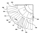
도 13을 참조하면, 텐셔너 허브(166)는 중앙 개구(202)를 형성하는 내부 환형 부분 또는 링(200) 및 슬롯(206)에 의해 분리된 텐셔너 암(204)을 포함하는 외부 부분을 포함할 수 있다. 암(204)은 도시된 바와 같이 링(200)으로부터 방사상 외측으로 연장될 수 있거나, 링(200)으로부터 곡선을 따라 연장될 수 있다. 텐셔너 허브(166)는 청소 도구(164)를 예압(pre-load)하기 위해, 즉, 청소 도구(164)를 청소할 표면에 닿도록 강제하기 위해 청소 도구(164)에 하향 힘을 가하기 위해 원추 형상일 수 있다. 돔 형상의 텐셔너 허브(166)와 같이, 청소 도구(164)를 예압하기 위한 다른 형태도 가능하다.Referring to FIG. 13 , the
각각의 암(204)은 링(200)에 부착된 제1 단부 또는 루트(208)로부터 제2단부 또는 팁(210)까지 연장될 수 있고, 상면(212) 및 저면(214)을 가질 수 있다. 저면(214)은 텐셔너 허브(166)가 청소 도구(164)와 조립될 때 청소 도구(164)를 누른다. 팁(210)은 허브(166)의 외주(216)를 집합 적으로 형성할 수 있다. 각 암(204)은 루트(208)를 팁(210)에 연결하는 이격된 측면 모서리(218)를 가질 수 있다. 인접한 암(204)의 측면 모서리(218)는 슬롯(206) 중 하나에 의해 분리된다. 암(204)은 실질적으로 단단할 수 있거나, 본 명세서에 도시된 바와 같이, 암(204)의 유연성을 증가시킬 수 있는 적어도 하나의 개구(220)를 내부에 포함할 수 있다.Each
암(204)은 회전축(V)에 대해 동일하게 이격될 수 있다. 예를 들어, 도시된 모서리 청소 브러시(160)의 실시예에서, 텐셔너 허브(166)는 서로 약 45 ° 이격된 8 개의 암(204)을 포함할 수 있다. 다른 암 개수 및 간격도 가능하다.The
암(204)은 상면 및 저면(212, 214) 사이의 거리로 정의되는 암 두께(AT), 루트(208)와 팁(210) 사이의 거리로 정의되는 암 길이(AL) 및 측면 모서리(218) 사이의 거리로 정의되는 암 폭(AW)을 갖는다. 암(204)은 두께(AT)가 길이(AL) 또는 폭(AW)보다 작은 편평한 부재일 수 있다. The
폭(AW)은 루트(208)에서 팁(210)까지 일정 할 수 있거나, 도시된 실시예에 알 수 있듯이 루트(208)에서 팁(210)으로 갈수록 증가하는 것과 같이 변할 수도 있다. 위에서 볼 수 있듯이, 도 10에서와 같이, 암(204)은 전체적으로 사다리꼴 형상을 갖는다. 정사각형, 직사각형, 평행사변형 또는 다른 다각형 모양과 같은 다른 암 형상도 가능하지만 이에 제한되는 것은 아니다. 또 다른 실시예에서, 개별 암(204)의 길이, 폭 및/또는 두께는 상이할 수 있다.The width AW may be constant from
도시된 원추형 텐셔너 허브(166)의 경우, 링(200)은 원추 형상의 상부 모서리를 형성하고 중심 개구(202)를 형성하는 링(200)의 내부 모서리(222)로부터 원추 형상의 하부 모서리를 형성하는 링(200)의 외부 모서리(224)로 갈수록 점점 가늘어지는, 절두 원추형(frustoconical)일 수 있다. 암(204)은 링(200)의 외부 또는 바닥 모서리(224)로부터 연장된다. 외부 또는 바닥 모서리(224)는 평면을 형성할 수 있고, 암(204)은 평면 아래에 배치될 수 있고, 평면으로부터 멀어지는 방향으로, 루트(208)로부터 팁(210)까지 일 각도로 연장될 수 있다.For the
도시된 실시예에서, 링(200)은 텐셔너 허브(166)의 중심에 가깝게 위치된다, 즉, 링(200)은 텐셔너 허브(166) 반경의 내측 절반부 내에 있다. 대안의 실시예에서, 링(200)은, 예컨대, 텐셔너 허브(166)의 반경의 외측 절반부 내에 있거나 또는 내측 절반부에서 외측 절반부로 부분적으로 연장함으로써, 강성을 증가시키고 청소 도구(164)의 홀딩 기능을 형성하기 위해 반경보다 더 멀리 위치할 수도 있다. 아래에서 더 상세히 설명되는 도 23은 브러시(160) 용 텐셔너 허브(166d)의 대안의 실시예를 도시한다.In the illustrated embodiment, the
슬롯(206)은 허브(166)의 외주(216)로부터 허브(166)의 중심을 향해 연장된다. 슬롯(206)은 외주(216)에서 개방되고 외주(216)의 내부에 배치된 슬롯 단부(226)까지 연장된다. 슬롯(206)은 벽 및 바닥 트림과 같은 평평하지 않은 표면에서의 편향을 위해 암(204)의 개별적인 굴곡을 허용한다. 대안의 실시예에서, 허브(166)는 충실할 수도 있고 핑거가 없을 수 있으며, 링 형상일 수 있다. 아래에 더 상세히 설명되는 도 24는 브러시(160)를 위한 충실형 텐셔너 허브(166e)의 대안의 실시예를 도시한다.The
암(204)의 팁(210)과 슬롯(206)의 단부(226)는 도시된 바와 같이 사각형으로 절단될 수 있다. 암(204) 및 슬롯(206)에 대한 다른 형태, 예를 들어, 둥글거나, 구부러지거나, 각진 형태도 가능하다. The
텐셔너 허브(166)는 탄성 열가소성 재료와 같은 엘라스토머 또는 공중합체 재료로 제조될 수 있으므로, 암(204)은 청소 도구(164)에 하향 힘을 제공할 만큼 충분히 뻣뻣하며, 청소 도구(164)가 작동 중에 청소 도구(116)와 표면(S) 사이에 과도한 항력(drag)을 생성하지 않으면서, 회전 중에 청소할 표면(S)과 접촉을 유지한다. 탄성 열가소성 재료의 한 예는 우레탄이며, 선택사항으로서 포괄적으로 72-90의 쇼어 A 경도를 가지며, 대안으로서 81의 쇼어 A 경도를 갖는다. 텐셔너 허브(166)에 적합한 또 다른 재료는 쇼어 A 경도가 70 인 열가소성 폴리우레탄(TPU)이다. 다른 엘라스토머 또는 공중합체 재료도 가능하다.The
모서리 청소 브러시(160)를 조립하기 위해, 텐셔너 허브(166)는 용접 또는 접착과 같은 적절한 부착 방법을 사용하여 청소 도구(164)에 부착될 수 있다. 암(204)의 저면(214)을 포함하는 텐셔너 허브(166)의 밑면은 청소 도구(164)의 상면에 부착되어 적어도 암(204)이 청소 도구(164)의 중앙부(174)와 완전히 접촉하도록 한다. 선택사항으로서, 링(200)의 저면은 또한 텐셔너 허브(166)와 청소 도구(164) 사이의 접촉을 증가시키기 위해 중앙부(174)에 부착된다. To assemble the
모서리 청소 브러시(160)의 특정 실시예에서, 청소 도구(164)는 다이 컷 마이크로스웨이드 패드를 포함하고, 고주파(HF) 용접을 사용하여 엘라스토머 또는 공중합체 재료의 텐셔너 허브(166)와 조립된다. 이 서브 어셈블리는 몰딩된 플라스틱 부착 허브(168)와 조립된다.In a particular embodiment of the
도 16-18은 일반적으로 160a로 표시된 모서리 청소 브러시의 또 다른 실시예의 세부 사항을 보여준다. 도 16-18의 실시예는 도 10-15에 도시된 모서리 청소 브러시(160)의 실시예와 실질적으로 유사하며, 유사한 엘리먼트들은 문자 "a"를 갖는 동일한 참조 번호로 지칭될 것이다. 모서리 청소 브러시(160a)는 모서리 청소 브러시(60L, 60R) 중 하나 또는 이 둘 모두를 대신하여 도 1-9에 도시된 진공 청소기(10) 상에 제공될 수 있고, 또는 벽, 베이스 보드, 캐비닛, 가구 등에 의해 만들어진 모서리 또는 모퉁이를 포함하여 방의 모서리 및 모퉁이를 따라 잘 닿지 않는 공간을 청소하기 위해 다른 표면 청소 장치 상에 제공될 수 있다. 모서리 청소 브러시(160a)는 실질적으로 수직인 회전축(V)을 중심으로 회전하도록 구성될 수 있다.16-18 show details of another embodiment of an edge cleaning brush, generally designated 160a. The embodiment of Figs. 16-18 is substantially similar to the embodiment of the
모서리 청소 브러시(160a)는 전술한 바와 같이 회전체(162a), 청소 도구(164a) 및 텐셔너 허브(166a)를 포함할 수 있지만, 다음과 같은 차이점이 있다. 텐셔너 허브(166a)는 청소 도구(164a)의 중앙부(174a) 뿐만 아니라 청소 도구(164a)의 핑거(176a) 위로 연장될 수 있다. 중앙 부(174a)는 텐셔너 허브(166a)의 링(200a)과 실질적으로 동시 확장될 수 있다.The
텐셔너 암(204a)은 핑거(176a) 위로 연장할 수 있으며, 텐셔너 암(204a)의 팁(210a)은 핑거(176a)의 팁(186a)의 안쪽으로 배치되고, 그리고 핑거(176a)의 팁(186a)은 텐셔너 허브(166a)의 둘레를 넘어 돌출되어 있다. 인접한 핑거(176a)를 분리하는 슬롯(194a)은 인접한 텐셔너 암(204a)을 분리하는 슬롯(206a)과 정렬될 수 있다.
핑거(176a)는 중앙부(174a)로부터 비-방사상으로 돌출할 수 있다. 따라서, 핑거(176a)는 중앙부(174a)와의 그들의 연결 지점에서 예각 및 둔각을 형성한다. 즉, 핑거(176a)는 브러시(160a)의 회전축(V)으로부터 취한 반경에 대해 일 각도를 이루고 비-방사상으로 정렬된다. 핑거(176a)를 비-방사상으로 형성함으로써, 핑거(176a)는 방사상으로 연장되는 것보다 길다. 따라서, 이 추가적인 길이는 핑거(176a)가 청소를 위해 더 큰 표면적을 형성할 수 있게 한다.
비-방사상으로 정렬되는 것에 추가하여, 핑거(176a)는 브러시(160a)의 회전 방향(R)으로 만곡될 수 있다. 핑거(176a)는 만곡 선단 모서리(192aL) 및 만곡 후단 모서리(192aT)를 갖는다. 만곡 선단 모서리(192aL)는 둔각으로 팁(186a)과 만날 수 있고, 만곡 후단 모서리(192aT)는 예각으로 팁(186a)과 만날 수 있다. In addition to being non-radially aligned, the
텐셔너 암(204a)은 링(200a)으로부터 비-방사상으로 돌출할 수 있다. 따라서, 암(204a)은 링(200a)과의 그들의 연결 지점에서 예각 및 둔각을 형성한다. 즉, 암(204a)은 브러시(160a)의 회전축(V)으로부터 취해진 반경에 대해 일 각도를 이루고 비-방사상으로 정렬된다. 비-방사상으로 암(204a)을 형성함으로써, 암(204a)은 핑거(176a) 위에 정렬되어 핑거(176a)를 청소할 표면에 대해 가압한다. 비-방사상으로 정렬되는 것에 추가하여, 텐셔너 암(204a)은 핑거(176a)의 곡률과 일치하도록 브러시(160a)의 회전 방향(R)으로 만곡될 수 있다.
핑거(176a) 및 암(204a)은 회전축(V)에 대해 동일하게 이격될 수 있다. 예를 들어, 도시된 모서리 청소 브러시(160a)의 실시예에서, 청소 도구(164a)는 서로 약 72 ° 이격된 5 개의 핑거 및 5 개의 암을 포함할 수 있다. 핑거 및 팔에 대한 다른 개수 및 간격도 가능하다.The
청소 요소와 텐셔너 허브의 다양한 조합이 가능하다. 예를 들어, 도 19는 일반적으로 160b로 표시된 모서리 청소 브러시의 또 다른 실시예를 도시하며, 여기서 유사한 엘리먼트는 문자 "b"를 갖는 동일한 참조 번호로 지칭될 것이다. 모서리 청소 브러시(160b)는 도 10-15의 실시예에 대해 설명된 바와 같은 핑거(176b)를 갖는 클리닝 패드(164b) 및 도 16-18의 실시예에 대해 설명된 바와 같은 텐셔너 허브(166b)를 포함할 수 있다.Various combinations of cleaning elements and tensioner hubs are possible. For example, FIG. 19 shows another embodiment of an edge cleaning brush, generally designated 160b, wherein like elements will be designated by the same reference number with the letter "b." The
도 20-22는 일반적으로 160c로 표시된 모서리 청소 브러시의 추가 실시예의 세부 사항을 도시하며, 여기서 유사한 엘리먼트는 문자 "c"를 갖는 동일한 참조 번호로 지칭될 것이다. 모서리 청소 브러시(160c)는 모서리 청소 브러시(60L, 60R) 중 하나 또는 이 둘 모두를 대신하여 도 1-9에 도시된 진공 청소기(10) 상에 제공될 수 있고, 또는 벽, 베이스 보드, 캐비닛, 가구 등에 의해 만들어진 모서리 또는 모퉁이를 포함하여 방의 모서리 및 모퉁이를 따라 잘 닿지 않는 공간을 청소하기 위해 다른 표면 청소 장치 상에 제공될 수 있다. 모서리 청소 브러시(160c)는 실질적으로 수직인 회전축(V)을 중심으로 회전하도록 구성될 수 있다.20-22 show details of a further embodiment of an edge cleaning brush, generally designated 160c, wherein like elements will be designated by the same reference number with the letter "c". The
모서리 청소 브러시(160c)는 전술한 바와 같이 회전체(162c), 청소 도구(164c) 및 텐셔너 허브(166c)를 포함할 수 있지만, 다음과 같은 차이점이 있다. 제2 청소 도구(264)는 제1 청소 도구(164c) 아래에 적층된다. 이러한 적층된 배열에서, 제1 청소 도구(164c)는 일반적으로 제2 청소 도구(264) 위에 놓일 수 있다. 청소 도구(164c, 264)는 모서리 청소 브러시(160c)의 회전축(V)을 따라 동심으로 정렬될 수 있다. 2개의 청소 도구가 여기에 도시되어 있지만, 다른 실시예에서는 3개 이상의 청소 도구가 제공되고 텐셔너 허브(166c)와 함께 적층될 수 있다.The
청소 도구(164c, 264)는 상이한 직경을 가질 수 있다. 도 21에서 가장 잘 볼 수 있는 바와 같이, 하부 청소 도구(264)는 상부 청소 도구(164c)의 직경(D1)보다 더 작은 직경(D2)을 갖는다. 따라서, 상부 청소 도구(164c)는 하부 청소 도구(264)를 넘어 연장된다.The
제2 청소 도구(264)는 제1 청소 도구(164c)와 유사 할 수 있으며, 내부 또는 중앙 부분(274)을 갖는 패드 및 중앙 부분(274)의 둘레부로부터 돌출하는 복수의 핑거(276)를 포함하는 외부 부분을 포함한다. 핑거(276)는 슬롯(294)에 의해 분리될 수 있다. 복수의 하부 핑거(276)는 텐셔너 허브(166c)의 둘레부를 넘어 돌출할 수 있고, 복수의 상부 핑거(176c)는 하부 핑거(276)의 팁을 넘어 돌출할 수 있다. 제1 청소 도구(164)의 재료, 제조 및 조립에 대한 본 명세서에 제공된 설명은 달리 언급되지 않는 한 제2 청소 도구(264)에 적용된다는 것을 이해해야 한다.The
청소 도구(164c, 264)는 부착 허브(168c)에 의해 함께 고정되는 것과 같이 고정 각도 관계로 함께 회전할 수 있다. 선택사항으로서, 하부 핑거(276)는 상부 핑거(176c) 사이의 슬롯(194)과 정렬될 수 있고, 상부 핑거(176c)는 하부 핑거(276) 사이의 슬롯(294)과 정렬 될 수 있다. 핑거(176c, 276)가 부분적으로 또는 완전히 서로 중첩되는 경우를 포함하여 다른 각도 관계도 가능하다. The
동작에 있어서, 각각의 청소 도구(164c, 264)의 적어도 일부는 바닥과 접촉 할 수 있고 선택사항으로서 베이스 보드와 접촉할 수 있다. 더 작은 직경으로 인해, 하부 청소 도구(264)는 상부 청소 도구(176c)가 베이스 보드를 올라갈 때에도 바닥 및 베이스 보드의 하부 부분, 예컨대, 1/4 라운드와의 접촉을 유지할 수 있다. 텐셔너 허브(166c)는 청소 도구(164c, 264)를 하향 힘을 가하여 앞서 설명 한 바와 같이 바닥 및 베이스 보드를 포함하는 청소할 표면과 접촉하도록 청소 도구(164c, 264)를 강제한다. 텐셔너 허브(166)는 또한 두 청소 도구(164c, 264) 모두에 구조적 지지를 제공한다.In operation, at least a portion of each
도 23은 텐셔너 허브(166d)의 또 다른 실시예의 상부 투시도이며, 유사한 엘리먼트는 문자 "d"를 갖는 동일한 참조 번호로 지칭될 것이다. 텐셔너 허브(166d)는 도 10-15의 실시예에 대해 설명 된 모서리 청소 브러시(160)와 같은 모서리 청소 브러시에 사용될 수 있다. 링(200d)은 텐셔너 허브(166d)의 반경의 바깥쪽에 더 위치하여 텐셔너 허브(166d)의 반경의 외측 절반부 내에 있는 것과 같이 강성을 증가시키고 청소 도구(미도시)의 홀딩 기능을 형성할 수 있다. 링(200d)으로부터 바깥쪽으로 연장하는 텐셔너 암(204d)을 갖는 것에 추가하여, 텐셔너 허브(166d)는 강성을 증가시키고 홀딩을 형성하는 것을 추가로 돕기 위해 링(200d)으로부터 내측으로 연장하는 강성 암(228)을 가질 수 있다.23 is a top perspective view of another embodiment of a
도 24는 텐셔너 허브(166e)의 또 다른 실시예의 상부 투시도이며, 여기서 유사한 엘리먼트는 문자 "e"를 갖는 동일한 참조 번호로 지칭될 것이다. 텐셔너 허브(166e)는 도 10-15의 실시예에 대해 설명된 모서리 청소 브러시(160)와 같은 모서리 청소 브러시에 사용될 수 있다. 텐셔너 허브(166e)는 솔리드 디스크이며 암을 포함하지 않는다. 텐셔너 허브(166e)는 청소 도구(도시되지 않음)를 예압하기 위해, 즉, 청소 도구가 청소할 표면과 접촉하도록 강제하기 위해 청소 도구에 하향 힘을 가하기 위해 원추형일 수 있다. 돔형 텐셔너 허브(166e)와 같이, 청소 도구를 예압하기 위한 다른 형태도 가능하다.24 is a top perspective view of another embodiment of a
텐셔너 허브(166e)는 선택사항으로서 회전체(162e) 및/또는 청소 도구(도시되지 않음)와의 부착을 위한 중앙 개구를 포함할 수 있으며, 따라서 링 형상 일 수 있다. 중앙 개구를 갖는 원추형 텐셔너 허브(166e)의 경우, 텐셔너 허브(166e)의 전체 형상은 절두 원추형일 수 있다. The
텐셔너 허브(166e)는 허브(166e)의 상면과 하면 사이의 거리로 정의되는 두께(HT)를 갖는다. 이 두께(HT)는 허브(166e)에 걸쳐 일정할 수도 있고, 또는 두께(HT)는 변할 수 있다. 일 실시예에서, 두께(HT)는 방사상으로 증가한다, 즉, 허브(166e)가 외부 둘레부(216e)에서 가장 두꺼워지도록 허브의 중심에서 외부 둘레부(216e)로 갈수록 증가한다.The
선택사항으로서, 텐셔너 허브(166e)는 서브 어셈블리를 형성하기 위해 회전체(162e)와 일체로 형성될 수 있고, 이어서, 예컨대, 접착 결합, 열-스테이킹 또는 오버몰딩에 의해 청소 도구(도시되지 않음)에 부착될 수 있다. 텐셔너 허브(166e) 및 회전체(162e)는 주입 몰딩, 적층 제조 또는 다른 적절한 공정을 통해 일체로 형성될 수 있다.Optionally, the
본 명세서에서는 직립형 바닥 청소기에 대해 도시되어 있지만, 본 명세서에 개시된 모서리 청소 브러시의 다양한 실시예는 다른 구성으로 배열 된 유사한 기능 시스템을 가진 표면 청소 장치 상에 제공될 수 있다. 예를 들어, 하나 이상의 모서리 청소 브러시를 갖는 자율 이동 가능한 하우징을 갖는 자율 또는 로봇 장치, 진공 호스에 의해 바퀴 달린 베이스에 연결된 하나 이상의 모서리 청소 브러시를 갖는 청소 도구를 갖는 캐니스터 장치, 비교적 작은 영역을 청소하기 위해 사용자가 휴대하도록 구성된 휴대 가능한 장치 또는 상업용 장치 등이 있다. 앞서 언급한 모든 청소기는 타일 및 경목과 같은 경질 저면과 카펫과 같은 연질 저면을 청소하는데 사용할 수 있고 건식 및 습식 청소를 모두 수행할 수 있는 멀티-플로어(multi-floor) 청소 장치로서 구성될 수 있다. 본 개시 내용의 양태는 또한 스팀 전달 기능을 갖는 표면 청소 장치와 같은 스팀 장치에 포함될 수 있다. 본 개시 내용의 양태는 또한 유체 전달 기능이 없는 표면 청소 장치와 같이, 회수 또는 건식 진공 기능만을 갖는 장치에 포함될 수 있다.Although shown herein for an upright floor cleaner, various embodiments of the edge cleaning brushes disclosed herein may be provided on surface cleaning devices having similar functional systems arranged in other configurations. For example, an autonomous or robotic device having an autonomously movable housing having one or more edge cleaning brushes, a canister device having a cleaning tool having one or more edge cleaning brushes connected to a wheeled base by a vacuum hose, for cleaning relatively small areas portable devices or commercial devices that are configured to be carried by a user to do so. All of the aforementioned vacuums can be used to clean hard floors such as tiles and hardwood, and soft floors such as carpets, and can be configured as multi-floor cleaning units that can perform both dry and wet cleaning. . Aspects of the present disclosure may also be incorporated into steam devices, such as surface cleaning devices having a steam delivery function. Aspects of the present disclosure may also be incorporated into devices having only a recovery or dry vacuum function, such as a surface cleaning device without a fluid transfer function.
앞서 설명되지 않은 범위까지, 본 발명의 다양한 실시예의 상이한 특징 및 구조는 원하는대로 서로 조합하여 사용될 수 있고 또는 개별적으로 사용될 수도 있다. 하나의 표면 청소기 또는 표면 청소 장치가 본 명세서에서 이러한 모든 특징을 갖는 것으로 예시되었으나, 이는 설명의 간결성을 위한 것으로 이러한 모든 특징이 조합되어 사용되어야 하고 그렇게 수행되어야 한다는 것을 의미하는 것이 아니다. 따라서, 상이한 실시예들의 다양한 특징들은 새로운 실시예가 명시적으로 설명되었는지 여부에 관계없이, 새로운 실시예를 형성하기 위해 원하는대로 다양한 청소 장치 구성에서 혼합 및 매칭될 수 있다.To the extent not previously described, the different features and structures of the various embodiments of the present invention may be used individually or in combination with each other as desired. Although a single surface cleaner or surface cleaning apparatus is illustrated herein as having all of these features, this is for the sake of brevity of description and does not imply that all of these features should be used or performed in combination. Accordingly, various features of different embodiments may be mixed and matched in various cleaning device configurations as desired to form a new embodiment, whether or not a new embodiment is explicitly described.
상기 설명은 본 개시물의 일반적 실시예 및 특정 실시예에 관한 것이다. 그러나 첨부된 청구항에 정의된 본 개시 내용의 정신과 더 넓은 양태에서 벗어나지 않고 다양한 변경 및 수정이 가능하며, 이는 균등론을 포함한 특허법의 원칙에 따라 해석되어야 한다. 이와 같이, 본 개시는 예시의 목적으로 제시되고 본 개시의 모든 실시예의 철저한 설명으로서 해석되거나 이러한 실시예와 관련하여 예시되거나 설명된 특정 요소로 청구항의 범위를 제한하는 것으로 해석되어서는 안 된다. 예를 들어, 관사 "하나", "하나의", "그" 또는 "상기"를 사용하여 단수 요소를 언급한 것은 그 요소를 단수로 제한하는 것으로 해석되어서는 안 된다.The above description relates to general and specific embodiments of the present disclosure. However, various changes and modifications may be made without departing from the spirit and broader aspects of the present disclosure as defined in the appended claims, which should be construed in accordance with the principles of patent law, including the doctrine of equivalents. As such, this disclosure is presented for purposes of illustration and should not be construed as an exhaustive description of all embodiments of the disclosure, or as limiting the scope of the claims to the specific elements illustrated or described in connection with such embodiments. For example, reference to a singular element using the articles "a," "an," "the," or "the," shall not be construed as limiting the element to the singular.
마찬가지로, 첨부된 청구항는 상세한 설명에 설명된 표현 및 특정 구성요소 또는 방법으로 제한되지 않으며, 첨부된 청구항의 범위 내에 속하는 특정 실시예 사이에서 달라질 수 있음을 이해해야 한다. 다양한 실시예의 특정 특징 또는 양태를 설명하기 위해 여기에 의존하는 임의의 마쿠쉬(Markush) 그룹과 관련하여, 다른 모든 마쿠쉬 구성원과 독립적인 각 마쿠쉬 그룹의 각 구성원으로부터 상이하고, 특별하고, 및/또는 예상치 못한 결과가 얻어질 수 있다. 마쿠쉬 그룹의 각 구성원은 개별적으로 또는 조합하여 의존할 수 있으며 첨부된 청구항의 범위 내에서 특정 실시예에 대한 적절한 지원을 제공한다.Likewise, it is to be understood that the appended claims are not limited to the specific elements or methods described in the detailed description and may vary between specific embodiments falling within the scope of the appended claims. With respect to any Markush group that relies thereon to describe specific features or aspects of various embodiments, it is different, special, and distinct from each member of each Markush group independent of all other Markush members; and /or unexpected results may be obtained. Each member of the Markush group may be relied upon individually or in combination to provide adequate support for specific embodiments within the scope of the appended claims.
Claims (20)
청소할 표면을 가로 질러 이동하도록 구성된 하우징;
오물 유입구 및 클린 에어 배출구를 구비한 상기 하우징을 통과하는 작업 공기 경로, 상기 오물 유입구와 유체 연통하는 흡입 소스, 및 쓰레기(debris) 수집기를 포함하는 진공 수집 시스템; 및
상기 하우징 상에 장착된 모서리 청소 브러시를 포함하고, 상기 모서리 청소 브러시는:
회전축을 중심으로 회전 가능한 부착 허브;
상기 청소할 표면과 접촉하도록 구성된 청소 도구; 및
상기 청소 도구에 하향 힘을 가하는 텐셔너 허브를 포함하는 것을 특징으로 하는 진공 청소기.A vacuum cleaner comprising:
a housing configured to move across the surface to be cleaned;
a vacuum collection system comprising a working air path through the housing having a dirt inlet and a clean air outlet, a suction source in fluid communication with the dirt inlet, and a debris collector; and
a corner cleaning brush mounted on the housing, the corner cleaning brush comprising:
an attachment hub rotatable about an axis of rotation;
a cleaning tool configured to contact the surface to be cleaned; and
and a tensioner hub for applying a downward force to the cleaning tool.
상기 브러시 롤은 상기 브러시 모터 및 상기 브러시 롤과 상기 브러시 모터 사이의 구동 커플링을 포함하는 구동 어셈블리에 작동 가능하게 결합되고 상기 구동 어셈블리에 의해 구동되며; 그리고
상기 모서리 청소 브러시는 상기 브러시 모터 및 상기 부착 허브와 상기 브러시 롤 사이의 구동 커플링을 포함하는 구동 어셈블리에 작동 가능하게 결합되고 상기 구동 어셈블리에 의해 구동되는 것을 특징으로 하는 진공 청소기.5. The method of claim 4, comprising a brush motor in the housing;
the brush roll is operatively coupled to and driven by a drive assembly comprising the brush motor and a drive coupling between the brush roll and the brush motor; and
wherein the edge cleaning brush is operatively coupled to and driven by a drive assembly comprising the brush motor and a drive coupling between the attachment hub and the brush roll.
함께 회전하도록 상기 브러시 롤과 작동 가능하게 결합된 웜;
상기 웜과 맞물리는 제1 기어 및 함께 회전하도록 상기 제1 기어와 결합된 제2 기어를 갖는 2단 종동 기어; 및
상기 2단 종동 기어의 회전력을 상기 모서리 청소 브러시의 상기 부착 허브와 결합된 종동 기어로 전달하기 위해 상기 제2 기어와 결합된 벨트를 포함하는 것을 특징으로 하는 진공 청소기.6. The method of claim 5, wherein the drive coupling between the attachment hub and the brush roll comprises:
a worm operatively associated with the brush roll for rotation therewith;
a two-stage driven gear having a first gear meshing with the worm and a second gear engaged with the first gear to rotate together; and
and a belt engaged with the second gear to transmit the rotational force of the second-stage driven gear to the driven gear engaged with the attachment hub of the edge cleaning brush.
청소할 표면을 가로질러 이동하도록 구성된 하우징;
상기 하우징에 장착된 모서리 청소 브러시를 포함하고, 상기 모서리 청소 브러시는:
회전축을 중심으로 회전 가능한 부착 허브;
상기 청소할 표면과 접촉하도록 구성된 청소 도구; 및
상기 청소 도구에 하향 힘을 가하는 텐셔너 허브를 포함하는 것을 특징으로 하는 표면 청소 장치.A surface cleaning device comprising:
a housing configured to move across a surface to be cleaned;
a corner cleaning brush mounted to the housing, wherein the corner cleaning brush comprises:
an attachment hub rotatable about an axis of rotation;
a cleaning tool configured to contact the surface to be cleaned; and
and a tensioner hub for applying a downward force to the cleaning tool.
상기 청소 도구는 중앙 부분 및 상기 중앙 부분의 둘레부로부터 돌출되는 복수의 핑거를 포함하는 외측 부분을 갖는 원형 마이크로스웨이드 패드를 포함하고;
상기 부착 허브, 적어도 하나의 마이크로스웨이드 패드 및 상기 텐셔너 허브는 상기 회전축을 따라 동심으로 정렬되고;
상기 텐셔너 허브는 상기 마이크로스웨이드 패드의 상기 중앙 부분 위로 연장되고, 상기 복수의 핑거는 상기 텐셔너 허브의 외주부를 넘어 연장되는 것을 특징으로 하는 표면 청소 장치.18. The method of claim 17,
wherein the cleaning tool comprises a circular micro suede pad having a central portion and an outer portion comprising a plurality of fingers projecting from a perimeter of the central portion;
the attachment hub, the at least one micro suede pad and the tensioner hub are concentrically aligned along the axis of rotation;
wherein the tensioner hub extends over the central portion of the micro suede pad, and the plurality of fingers extend beyond an outer periphery of the tensioner hub.
청소할 표면을 가로 질러 이동하도록 구성된 하우징;
브러시 모터;
브러시 롤 축을 중심으로 회전 가능하고, 상기 브러시 모터에 작동 가능하게 결합되고 상기 브러시 모터에 의해 구동되는 브러시 롤;
상기 하우징에 장착되고, 상기 브러시 모터에 작동 가능하게 결합되고 상기 브러시 모터에 의해 구동되는 모서리 청소 브러시로서,
상기 브러시 롤 축에 실질적으로 수직인 회전 축을 중심으로 회전 가능한 부착 허브; 및
상기 청소할 표면과 접촉하도록 구성된 청소 도구를 포함하는 것인 상기 모서리 청소 브러시; 및
상기 부착 허브와 상기 브러시 롤 사이의 구동 커플링을 포함하고,
상기 구동 커플링은:
함께 회전하도록 상기 브러시 롤과 작동 가능하게 결합된 웜;
상기 웜과 맞물리는 제1 기어 및 함께 회전하도록 상기 제1 기어와 결합된 제2 기어를 갖는 2단 종동 기어; 및
상기 2단 종동 기어의 회전력을 상기 모서리 청소 브러시의 상기 부착 허브에 결합된 종동 기어로 전달하기 위해 상기 제2 기어와 결합된 벨트를 포함하는 것을 특징으로 하는 표면 청소 장치.A surface cleaning device comprising:
a housing configured to move across the surface to be cleaned;
brush motor;
a brush roll rotatable about a brush roll axis, operatively coupled to and driven by the brush motor;
an edge cleaning brush mounted to the housing, operatively coupled to the brush motor and driven by the brush motor;
an attachment hub rotatable about an axis of rotation substantially perpendicular to the brush roll axis; and
the edge cleaning brush comprising a cleaning tool configured to contact the surface to be cleaned; and
a drive coupling between the attachment hub and the brush roll;
The drive coupling comprises:
a worm operatively associated with the brush roll for rotation therewith;
a two-stage driven gear having a first gear meshing with the worm and a second gear engaged with the first gear to rotate together; and
and a belt coupled to the second gear for transmitting the rotational force of the second-stage driven gear to the driven gear coupled to the attachment hub of the edge cleaning brush.
Applications Claiming Priority (2)
| Application Number | Priority Date | Filing Date | Title |
|---|---|---|---|
| US202063001573P | 2020-03-30 | 2020-03-30 | |
| US63/001,573 | 2020-03-30 |
Publications (1)
| Publication Number | Publication Date |
|---|---|
| KR20210122152A true KR20210122152A (en) | 2021-10-08 |
Family
ID=75252510
Family Applications (1)
| Application Number | Title | Priority Date | Filing Date |
|---|---|---|---|
| KR1020210039319A KR20210122152A (en) | 2020-03-30 | 2021-03-26 | Edge cleaning brushes for floor cleaner |
Country Status (8)
| Country | Link |
|---|---|
| US (2) | US11284759B2 (en) |
| EP (1) | EP3900592B1 (en) |
| JP (1) | JP2021159764A (en) |
| KR (1) | KR20210122152A (en) |
| CN (2) | CN113455963A (en) |
| AU (1) | AU2021201868A1 (en) |
| BR (1) | BR102021005917A2 (en) |
| CA (1) | CA3113514A1 (en) |
Families Citing this family (3)
| Publication number | Priority date | Publication date | Assignee | Title |
|---|---|---|---|---|
| USD999469S1 (en) * | 2022-01-05 | 2023-09-19 | Beijing Roborock Technology Co., Ltd. | Dust box with water tank for cleaning appliance |
| CN114305250B (en) * | 2022-01-20 | 2023-10-10 | 深圳乐生机器人智能科技有限公司 | Cleaning system and cleaning equipment |
| CN114504266A (en) * | 2022-03-14 | 2022-05-17 | 苏州荣炫电器有限公司 | Driving mechanism of floor brush head and low-energy-consumption environment-friendly floor brush head comprising same |
Family Cites Families (23)
| Publication number | Priority date | Publication date | Assignee | Title |
|---|---|---|---|---|
| US1673160A (en) * | 1924-06-06 | 1928-06-12 | Charles H Fennell | Mechanism for rubbing and polishing |
| US4032239A (en) * | 1975-09-17 | 1977-06-28 | Maupin Roger A | Scrubbing apparatus |
| US4739534A (en) * | 1984-07-19 | 1988-04-26 | Pioneer/Eclipse Corp. | High speed floor buffing pad and holder |
| US4709439A (en) * | 1986-07-14 | 1987-12-01 | Warren William L | Mounting disk for a floor polisher |
| US4747176A (en) * | 1987-06-01 | 1988-05-31 | Daisy Janitorial Service, Inc. | Padholder for floor polisher |
| DE9403678U1 (en) | 1994-03-05 | 1994-05-26 | Kraenzle Josef | Sweeper with at least one side feed brush |
| US5533222A (en) * | 1995-03-28 | 1996-07-09 | Lelkes; Anthony | Floor and baseboard treatment machine |
| ES2182697B2 (en) * | 2001-05-10 | 2004-07-16 | Jaz-Zubiaurre, S.A. | INDUSTRIAL BRUSH |
| KR100704483B1 (en) * | 2005-04-25 | 2007-04-09 | 엘지전자 주식회사 | a corner cleaning apparatus of a robot sweeper |
| US7328477B1 (en) * | 2006-08-21 | 2008-02-12 | Sanjay Aiyar | Dual-mode contour-following mop |
| US7908701B1 (en) * | 2006-08-21 | 2011-03-22 | Sanjay Aiyar | Adjustable contour-following mop |
| US20100107356A1 (en) * | 2008-11-03 | 2010-05-06 | Jakubos James D | Nozzle brush arrangements for vacuum cleaner assemblies |
| KR101322537B1 (en) * | 2009-06-30 | 2013-10-28 | 엘지전자 주식회사 | A robot cleanner |
| US8631541B2 (en) * | 2011-08-23 | 2014-01-21 | Bissell Homecare, Inc. | Auxiliary brush for vacuum cleaner |
| JP2014046207A (en) * | 2012-08-30 | 2014-03-17 | Samsung Electronics Co Ltd | Side brush assembly, robot cleaner and control method for the same |
| KR101469333B1 (en) * | 2012-12-26 | 2014-12-04 | 엘지전자 주식회사 | Automatic cleaner |
| DE102014100013A1 (en) | 2014-01-02 | 2015-07-02 | Miele & Cie. Kg | Autonomous tillage implement |
| KR102137524B1 (en) * | 2014-02-13 | 2020-07-24 | 삼성전자주식회사 | Robot cleaner |
| US11445809B2 (en) * | 2014-09-04 | 2022-09-20 | Florida Institute of Technology, Inc. | Vertically rotating grooming attachment brush and method of use |
| AU2016101847B4 (en) | 2015-10-28 | 2022-02-17 | Bissell Inc. | Surface cleaning apparatus |
| US10582825B2 (en) * | 2016-10-06 | 2020-03-10 | Dean Paavola | Modular surface maintainer |
| KR20210070191A (en) * | 2019-12-04 | 2021-06-14 | 비쎌 인코포레이티드 | Handheld extraction cleaner |
| KR20210128601A (en) * | 2020-04-17 | 2021-10-27 | 엘지전자 주식회사 | Robot Cleaner |
-
2021
- 2021-03-22 US US17/207,807 patent/US11284759B2/en active Active
- 2021-03-24 AU AU2021201868A patent/AU2021201868A1/en active Pending
- 2021-03-26 BR BR102021005917-6A patent/BR102021005917A2/en not_active Application Discontinuation
- 2021-03-26 EP EP21165395.1A patent/EP3900592B1/en active Active
- 2021-03-26 KR KR1020210039319A patent/KR20210122152A/en unknown
- 2021-03-29 CN CN202110335162.0A patent/CN113455963A/en active Pending
- 2021-03-29 CN CN202120636497.1U patent/CN215016897U/en active Active
- 2021-03-29 JP JP2021054990A patent/JP2021159764A/en active Pending
- 2021-03-29 CA CA3113514A patent/CA3113514A1/en active Pending
-
2022
- 2022-02-21 US US17/676,313 patent/US20220175204A1/en active Pending
Also Published As
| Publication number | Publication date |
|---|---|
| US20220175204A1 (en) | 2022-06-09 |
| CA3113514A1 (en) | 2021-09-30 |
| US20210298548A1 (en) | 2021-09-30 |
| AU2021201868A1 (en) | 2021-10-14 |
| JP2021159764A (en) | 2021-10-11 |
| BR102021005917A2 (en) | 2021-10-05 |
| EP3900592B1 (en) | 2024-04-24 |
| US11284759B2 (en) | 2022-03-29 |
| CN113455963A (en) | 2021-10-01 |
| CN215016897U (en) | 2021-12-07 |
| EP3900592A3 (en) | 2022-01-05 |
| EP3900592A2 (en) | 2021-10-27 |
Similar Documents
| Publication | Publication Date | Title |
|---|---|---|
| CN215016897U (en) | Vacuum cleaner and surface cleaning apparatus | |
| US9993127B2 (en) | Vacuum cleaner | |
| JP5227451B2 (en) | Vacuum cleaner head | |
| AU2010212337B2 (en) | Vacuum accessory tool | |
| US7293322B2 (en) | Cleaning attachment for vacuum cleaner | |
| JP2021041163A (en) | Edge cleaning brushes for floor cleaner | |
| US10973379B2 (en) | Agitator with disks | |
| US8484800B2 (en) | Cleaner head | |
| JP5227452B2 (en) | Vacuum cleaner head | |
| GB2492005A (en) | A cleaner head | |
| GB2486442A (en) | An agitator |