BR102021005917A2 - DUST CLEANER, E, SURFACE CLEANING APPLIANCE - Google Patents
DUST CLEANER, E, SURFACE CLEANING APPLIANCE Download PDFInfo
- Publication number
- BR102021005917A2 BR102021005917A2 BR102021005917-6A BR102021005917A BR102021005917A2 BR 102021005917 A2 BR102021005917 A2 BR 102021005917A2 BR 102021005917 A BR102021005917 A BR 102021005917A BR 102021005917 A2 BR102021005917 A2 BR 102021005917A2
- Authority
- BR
- Brazil
- Prior art keywords
- brush
- cleaning
- hub
- edge
- vacuum cleaner
- Prior art date
Links
- 238000004140 cleaning Methods 0.000 title claims abstract description 318
- 239000000428 dust Substances 0.000 title description 11
- 230000008878 coupling Effects 0.000 claims abstract description 39
- 238000010168 coupling process Methods 0.000 claims abstract description 39
- 238000005859 coupling reaction Methods 0.000 claims abstract description 39
- 239000012530 fluid Substances 0.000 claims description 19
- 238000004891 communication Methods 0.000 claims description 6
- 239000000463 material Substances 0.000 description 11
- 239000007787 solid Substances 0.000 description 8
- 229920001410 Microfiber Polymers 0.000 description 7
- 238000011084 recovery Methods 0.000 description 7
- 230000005540 biological transmission Effects 0.000 description 6
- 239000004744 fabric Substances 0.000 description 5
- 238000000034 method Methods 0.000 description 5
- 230000002093 peripheral effect Effects 0.000 description 5
- 230000000712 assembly Effects 0.000 description 4
- 238000000429 assembly Methods 0.000 description 4
- 238000004519 manufacturing process Methods 0.000 description 4
- 239000003658 microfiber Substances 0.000 description 4
- 238000010408 sweeping Methods 0.000 description 4
- 238000011144 upstream manufacturing Methods 0.000 description 4
- 230000001154 acute effect Effects 0.000 description 3
- 229920001577 copolymer Polymers 0.000 description 3
- 239000007788 liquid Substances 0.000 description 3
- 229920001778 nylon Polymers 0.000 description 3
- 239000004677 Nylon Substances 0.000 description 2
- PPBRXRYQALVLMV-UHFFFAOYSA-N Styrene Chemical compound C=CC1=CC=CC=C1 PPBRXRYQALVLMV-UHFFFAOYSA-N 0.000 description 2
- 239000004433 Thermoplastic polyurethane Substances 0.000 description 2
- 239000000654 additive Substances 0.000 description 2
- 230000000996 additive effect Effects 0.000 description 2
- 238000004026 adhesive bonding Methods 0.000 description 2
- 239000000835 fiber Substances 0.000 description 2
- 239000006260 foam Substances 0.000 description 2
- 239000011121 hardwood Substances 0.000 description 2
- 238000001746 injection moulding Methods 0.000 description 2
- 239000003595 mist Substances 0.000 description 2
- 239000004033 plastic Substances 0.000 description 2
- 229920001707 polybutylene terephthalate Polymers 0.000 description 2
- 229920000728 polyester Polymers 0.000 description 2
- -1 polypropylene Polymers 0.000 description 2
- 230000036316 preload Effects 0.000 description 2
- 230000008569 process Effects 0.000 description 2
- 239000012815 thermoplastic material Substances 0.000 description 2
- 229920002803 thermoplastic polyurethane Polymers 0.000 description 2
- XLYOFNOQVPJJNP-UHFFFAOYSA-N water Chemical compound O XLYOFNOQVPJJNP-UHFFFAOYSA-N 0.000 description 2
- JOYRKODLDBILNP-UHFFFAOYSA-N Ethyl urethane Chemical compound CCOC(N)=O JOYRKODLDBILNP-UHFFFAOYSA-N 0.000 description 1
- 241001417527 Pempheridae Species 0.000 description 1
- 239000004952 Polyamide Substances 0.000 description 1
- 239000004743 Polypropylene Substances 0.000 description 1
- 239000004676 acrylonitrile butadiene styrene Substances 0.000 description 1
- 230000009471 action Effects 0.000 description 1
- 230000004075 alteration Effects 0.000 description 1
- 238000005452 bending Methods 0.000 description 1
- 230000001680 brushing effect Effects 0.000 description 1
- 238000010276 construction Methods 0.000 description 1
- 230000009977 dual effect Effects 0.000 description 1
- 238000010410 dusting Methods 0.000 description 1
- 239000003292 glue Substances 0.000 description 1
- 230000014759 maintenance of location Effects 0.000 description 1
- 239000011159 matrix material Substances 0.000 description 1
- 230000007246 mechanism Effects 0.000 description 1
- 239000002184 metal Substances 0.000 description 1
- 239000002991 molded plastic Substances 0.000 description 1
- 229920003023 plastic Polymers 0.000 description 1
- 229920002647 polyamide Polymers 0.000 description 1
- 229920001155 polypropylene Polymers 0.000 description 1
- 238000011045 prefiltration Methods 0.000 description 1
- 230000009467 reduction Effects 0.000 description 1
- 230000002787 reinforcement Effects 0.000 description 1
- 230000008439 repair process Effects 0.000 description 1
- 239000002689 soil Substances 0.000 description 1
- 238000005476 soldering Methods 0.000 description 1
- 238000003756 stirring Methods 0.000 description 1
- 239000004575 stone Substances 0.000 description 1
- 239000000454 talc Substances 0.000 description 1
- 229910052623 talc Inorganic materials 0.000 description 1
- 238000010407 vacuum cleaning Methods 0.000 description 1
- 238000003466 welding Methods 0.000 description 1
- 238000005200 wet scrubbing Methods 0.000 description 1
Images


Classifications
-
- A—HUMAN NECESSITIES
- A47—FURNITURE; DOMESTIC ARTICLES OR APPLIANCES; COFFEE MILLS; SPICE MILLS; SUCTION CLEANERS IN GENERAL
- A47L—DOMESTIC WASHING OR CLEANING; SUCTION CLEANERS IN GENERAL
- A47L9/00—Details or accessories of suction cleaners, e.g. mechanical means for controlling the suction or for effecting pulsating action; Storing devices specially adapted to suction cleaners or parts thereof; Carrying-vehicles specially adapted for suction cleaners
- A47L9/02—Nozzles
- A47L9/04—Nozzles with driven brushes or agitators
- A47L9/0461—Dust-loosening tools, e.g. agitators, brushes
- A47L9/0488—Combinations or arrangements of several tools, e.g. edge cleaning tools
-
- A—HUMAN NECESSITIES
- A47—FURNITURE; DOMESTIC ARTICLES OR APPLIANCES; COFFEE MILLS; SPICE MILLS; SUCTION CLEANERS IN GENERAL
- A47L—DOMESTIC WASHING OR CLEANING; SUCTION CLEANERS IN GENERAL
- A47L9/00—Details or accessories of suction cleaners, e.g. mechanical means for controlling the suction or for effecting pulsating action; Storing devices specially adapted to suction cleaners or parts thereof; Carrying-vehicles specially adapted for suction cleaners
- A47L9/02—Nozzles
- A47L9/04—Nozzles with driven brushes or agitators
- A47L9/0461—Dust-loosening tools, e.g. agitators, brushes
- A47L9/0466—Rotating tools
- A47L9/0472—Discs
-
- A—HUMAN NECESSITIES
- A47—FURNITURE; DOMESTIC ARTICLES OR APPLIANCES; COFFEE MILLS; SPICE MILLS; SUCTION CLEANERS IN GENERAL
- A47L—DOMESTIC WASHING OR CLEANING; SUCTION CLEANERS IN GENERAL
- A47L9/00—Details or accessories of suction cleaners, e.g. mechanical means for controlling the suction or for effecting pulsating action; Storing devices specially adapted to suction cleaners or parts thereof; Carrying-vehicles specially adapted for suction cleaners
- A47L9/02—Nozzles
- A47L9/04—Nozzles with driven brushes or agitators
- A47L9/0405—Driving means for the brushes or agitators
- A47L9/0411—Driving means for the brushes or agitators driven by electric motor
-
- A—HUMAN NECESSITIES
- A47—FURNITURE; DOMESTIC ARTICLES OR APPLIANCES; COFFEE MILLS; SPICE MILLS; SUCTION CLEANERS IN GENERAL
- A47L—DOMESTIC WASHING OR CLEANING; SUCTION CLEANERS IN GENERAL
- A47L11/00—Machines for cleaning floors, carpets, furniture, walls, or wall coverings
- A47L11/24—Floor-sweeping machines, motor-driven
-
- A—HUMAN NECESSITIES
- A46—BRUSHWARE
- A46B—BRUSHES
- A46B13/00—Brushes with driven brush bodies or carriers
- A46B13/001—Cylindrical or annular brush bodies
- A46B13/005—Cylindrical or annular brush bodies made up of a series of longitudinal strips or segments
-
- A—HUMAN NECESSITIES
- A46—BRUSHWARE
- A46B—BRUSHES
- A46B13/00—Brushes with driven brush bodies or carriers
- A46B13/02—Brushes with driven brush bodies or carriers power-driven carriers
-
- A—HUMAN NECESSITIES
- A46—BRUSHWARE
- A46B—BRUSHES
- A46B9/00—Arrangements of the bristles in the brush body
- A46B9/005—Arrangements of the bristles in the brush body where the brushing material is not made of bristles, e.g. sponge, rubber or paper
-
- A—HUMAN NECESSITIES
- A46—BRUSHWARE
- A46B—BRUSHES
- A46B9/00—Arrangements of the bristles in the brush body
- A46B9/02—Position or arrangement of bristles in relation to surface of the brush body, e.g. inclined, in rows, in groups
- A46B9/026—Position or arrangement of bristles in relation to surface of the brush body, e.g. inclined, in rows, in groups where the surface of the brush body or carrier is not in one plane, e.g. not flat
-
- A—HUMAN NECESSITIES
- A46—BRUSHWARE
- A46D—MANUFACTURE OF BRUSHES
- A46D1/00—Bristles; Selection of materials for bristles
- A46D1/02—Bristles details
- A46D1/0207—Bristles characterised by the choice of material, e.g. metal
-
- A—HUMAN NECESSITIES
- A47—FURNITURE; DOMESTIC ARTICLES OR APPLIANCES; COFFEE MILLS; SPICE MILLS; SUCTION CLEANERS IN GENERAL
- A47L—DOMESTIC WASHING OR CLEANING; SUCTION CLEANERS IN GENERAL
- A47L11/00—Machines for cleaning floors, carpets, furniture, walls, or wall coverings
- A47L11/40—Parts or details of machines not provided for in groups A47L11/02 - A47L11/38, or not restricted to one of these groups, e.g. handles, arrangements of switches, skirts, buffers, levers
- A47L11/4013—Contaminants collecting devices, i.e. hoppers, tanks or the like
-
- A—HUMAN NECESSITIES
- A47—FURNITURE; DOMESTIC ARTICLES OR APPLIANCES; COFFEE MILLS; SPICE MILLS; SUCTION CLEANERS IN GENERAL
- A47L—DOMESTIC WASHING OR CLEANING; SUCTION CLEANERS IN GENERAL
- A47L11/00—Machines for cleaning floors, carpets, furniture, walls, or wall coverings
- A47L11/40—Parts or details of machines not provided for in groups A47L11/02 - A47L11/38, or not restricted to one of these groups, e.g. handles, arrangements of switches, skirts, buffers, levers
- A47L11/4036—Parts or details of the surface treating tools
- A47L11/4041—Roll shaped surface treating tools
-
- A—HUMAN NECESSITIES
- A47—FURNITURE; DOMESTIC ARTICLES OR APPLIANCES; COFFEE MILLS; SPICE MILLS; SUCTION CLEANERS IN GENERAL
- A47L—DOMESTIC WASHING OR CLEANING; SUCTION CLEANERS IN GENERAL
- A47L11/00—Machines for cleaning floors, carpets, furniture, walls, or wall coverings
- A47L11/40—Parts or details of machines not provided for in groups A47L11/02 - A47L11/38, or not restricted to one of these groups, e.g. handles, arrangements of switches, skirts, buffers, levers
- A47L11/4094—Accessories to be used in combination with conventional vacuum-cleaning devices
-
- A—HUMAN NECESSITIES
- A47—FURNITURE; DOMESTIC ARTICLES OR APPLIANCES; COFFEE MILLS; SPICE MILLS; SUCTION CLEANERS IN GENERAL
- A47L—DOMESTIC WASHING OR CLEANING; SUCTION CLEANERS IN GENERAL
- A47L9/00—Details or accessories of suction cleaners, e.g. mechanical means for controlling the suction or for effecting pulsating action; Storing devices specially adapted to suction cleaners or parts thereof; Carrying-vehicles specially adapted for suction cleaners
- A47L9/02—Nozzles
- A47L9/04—Nozzles with driven brushes or agitators
- A47L9/0427—Gearing or transmission means therefor
- A47L9/0433—Toothed gearings
- A47L9/0438—Toothed gearings with gears having orbital motion, e.g. planetary gearing
-
- A—HUMAN NECESSITIES
- A47—FURNITURE; DOMESTIC ARTICLES OR APPLIANCES; COFFEE MILLS; SPICE MILLS; SUCTION CLEANERS IN GENERAL
- A47L—DOMESTIC WASHING OR CLEANING; SUCTION CLEANERS IN GENERAL
- A47L9/00—Details or accessories of suction cleaners, e.g. mechanical means for controlling the suction or for effecting pulsating action; Storing devices specially adapted to suction cleaners or parts thereof; Carrying-vehicles specially adapted for suction cleaners
- A47L9/02—Nozzles
- A47L9/04—Nozzles with driven brushes or agitators
- A47L9/0427—Gearing or transmission means therefor
- A47L9/0444—Gearing or transmission means therefor for conveying motion by endless flexible members, e.g. belts
-
- A—HUMAN NECESSITIES
- A47—FURNITURE; DOMESTIC ARTICLES OR APPLIANCES; COFFEE MILLS; SPICE MILLS; SUCTION CLEANERS IN GENERAL
- A47L—DOMESTIC WASHING OR CLEANING; SUCTION CLEANERS IN GENERAL
- A47L9/00—Details or accessories of suction cleaners, e.g. mechanical means for controlling the suction or for effecting pulsating action; Storing devices specially adapted to suction cleaners or parts thereof; Carrying-vehicles specially adapted for suction cleaners
- A47L9/02—Nozzles
- A47L9/04—Nozzles with driven brushes or agitators
- A47L9/0461—Dust-loosening tools, e.g. agitators, brushes
- A47L9/0466—Rotating tools
- A47L9/0477—Rolls
-
- A—HUMAN NECESSITIES
- A46—BRUSHWARE
- A46B—BRUSHES
- A46B2200/00—Brushes characterized by their functions, uses or applications
- A46B2200/30—Brushes for cleaning or polishing
- A46B2200/3033—Household brush, i.e. brushes for cleaning in the house or dishes
-
- A—HUMAN NECESSITIES
- A47—FURNITURE; DOMESTIC ARTICLES OR APPLIANCES; COFFEE MILLS; SPICE MILLS; SUCTION CLEANERS IN GENERAL
- A47L—DOMESTIC WASHING OR CLEANING; SUCTION CLEANERS IN GENERAL
- A47L2201/00—Robotic cleaning machines, i.e. with automatic control of the travelling movement or the cleaning operation
-
- A—HUMAN NECESSITIES
- A47—FURNITURE; DOMESTIC ARTICLES OR APPLIANCES; COFFEE MILLS; SPICE MILLS; SUCTION CLEANERS IN GENERAL
- A47L—DOMESTIC WASHING OR CLEANING; SUCTION CLEANERS IN GENERAL
- A47L5/00—Structural features of suction cleaners
- A47L5/12—Structural features of suction cleaners with power-driven air-pumps or air-compressors, e.g. driven by motor vehicle engine vacuum
- A47L5/22—Structural features of suction cleaners with power-driven air-pumps or air-compressors, e.g. driven by motor vehicle engine vacuum with rotary fans
- A47L5/225—Convertible suction cleaners, i.e. convertible between different types thereof, e.g. from upright suction cleaners to sledge-type suction cleaners
-
- A—HUMAN NECESSITIES
- A47—FURNITURE; DOMESTIC ARTICLES OR APPLIANCES; COFFEE MILLS; SPICE MILLS; SUCTION CLEANERS IN GENERAL
- A47L—DOMESTIC WASHING OR CLEANING; SUCTION CLEANERS IN GENERAL
- A47L5/00—Structural features of suction cleaners
- A47L5/12—Structural features of suction cleaners with power-driven air-pumps or air-compressors, e.g. driven by motor vehicle engine vacuum
- A47L5/22—Structural features of suction cleaners with power-driven air-pumps or air-compressors, e.g. driven by motor vehicle engine vacuum with rotary fans
- A47L5/28—Suction cleaners with handles and nozzles fixed on the casings, e.g. wheeled suction cleaners with steering handle
- A47L5/30—Suction cleaners with handles and nozzles fixed on the casings, e.g. wheeled suction cleaners with steering handle with driven dust-loosening tools, e.g. rotating brushes
-
- A—HUMAN NECESSITIES
- A47—FURNITURE; DOMESTIC ARTICLES OR APPLIANCES; COFFEE MILLS; SPICE MILLS; SUCTION CLEANERS IN GENERAL
- A47L—DOMESTIC WASHING OR CLEANING; SUCTION CLEANERS IN GENERAL
- A47L9/00—Details or accessories of suction cleaners, e.g. mechanical means for controlling the suction or for effecting pulsating action; Storing devices specially adapted to suction cleaners or parts thereof; Carrying-vehicles specially adapted for suction cleaners
- A47L9/0072—Mechanical means for controlling the suction or for effecting pulsating action
-
- A—HUMAN NECESSITIES
- A47—FURNITURE; DOMESTIC ARTICLES OR APPLIANCES; COFFEE MILLS; SPICE MILLS; SUCTION CLEANERS IN GENERAL
- A47L—DOMESTIC WASHING OR CLEANING; SUCTION CLEANERS IN GENERAL
- A47L9/00—Details or accessories of suction cleaners, e.g. mechanical means for controlling the suction or for effecting pulsating action; Storing devices specially adapted to suction cleaners or parts thereof; Carrying-vehicles specially adapted for suction cleaners
- A47L9/10—Filters; Dust separators; Dust removal; Automatic exchange of filters
- A47L9/102—Dust separators
-
- A—HUMAN NECESSITIES
- A47—FURNITURE; DOMESTIC ARTICLES OR APPLIANCES; COFFEE MILLS; SPICE MILLS; SUCTION CLEANERS IN GENERAL
- A47L—DOMESTIC WASHING OR CLEANING; SUCTION CLEANERS IN GENERAL
- A47L9/00—Details or accessories of suction cleaners, e.g. mechanical means for controlling the suction or for effecting pulsating action; Storing devices specially adapted to suction cleaners or parts thereof; Carrying-vehicles specially adapted for suction cleaners
- A47L9/10—Filters; Dust separators; Dust removal; Automatic exchange of filters
- A47L9/106—Dust removal
Abstract
aspirador de pó, e, aparelho de limpeza de superfície. um aparelho de limpeza de superfície pode incluir um alojamento adaptado para se mover através de uma superfície a ser limpa, e uma escova de limpeza de borda provida no alojamento. a escova de limpeza de borda pode incluir um cubo de fixação conectável a um acoplamento de acionamento para rodar a escova, um instrumento de limpeza configurado para fazer contato com a superfície a ser limpa, e um cubo tensor aplicando força descendente no instrumento de limpeza. acoplamentos de acionamento para a escova de limpeza de borda são também descritos, tais como acoplamentos de acionamento incluindo uma rosca sem fim e correia que são indiretamente acionados por meio de um rolo de escova.vacuum cleaner, and surface cleaning apparatus. A surface cleaning apparatus may include a housing adapted to move across a surface to be cleaned, and an edge cleaning brush provided in the housing. The edge cleaning brush may include an attachment hub connectable to a drive coupling for rotating the brush, a cleaning instrument configured to make contact with the surface to be cleaned, and a tensioning hub applying downward force to the cleaning instrument. Drive couplings for the edge cleaning brush are also described, such as drive couplings including a worm and belt that are indirectly driven by means of a brush roll.
Description
[001] Limpadores de piso incluem um ou mais instrumentos de limpeza para remover detritos da superfície do piso. Por exemplo, escovas são usada para impulsionar detritos para um bocal de sucção ou entrada de detritos. Uma escova de limpeza lateral ou de borda pode rodar em torno de um eixo geométrico substancialmente vertical e varrer detritos sob o limpador de piso para coleta, e limpar espaços difíceis de alcançar tal como ao longo das bordas e nos cantos de uma sala, incluindo bordas ou cantos criados por paredes, rodapés, armários, móveis, etc. Tais escovas de limpeza de borda frequentemente têm cerdas que podem arremessar detritos para fora do trajeto de limpeza do limpador de piso, em vez de coletar detritos. Um outro problema com algumas escovas de limpeza de borda é que o sistema de acionamento para rodar a escova de limpeza de borda limita onde a escova de limpeza de borda pode ser colocada no limpador de piso.[001] Floor cleaners include one or more cleaning instruments to remove debris from the floor surface. For example, brushes are used to propel debris into a suction nozzle or debris inlet. A side or edge cleaning brush can rotate around a substantially vertical axis and sweep debris under the floor cleaner for collection, and clean hard-to-reach spaces such as along the edges and corners of a room, including edges. or corners created by walls, baseboards, cabinets, furniture, etc. Such edge cleaning brushes often have bristles that can hurl debris out of the floor cleaner's cleaning path instead of collecting debris. Another problem with some edge cleaning brushes is that the drive system to rotate the edge cleaning brush limits where the edge cleaning brush can be placed on the floor cleaner.
[002] Em um aspecto, a descrição se refere a uma escova de limpeza de borda para um limpador de piso ou aparelho de limpeza de superfície. A escova de limpeza de borda pode incluir um cubo de fixação conectável com um acoplamento de acionamento para rodar a escova, um instrumento de limpeza configurado para fazer contato com a superfície a ser limpa, e um cubo tensor que aplica força descendente no instrumento de limpeza.[002] In one aspect, the description refers to an edge cleaning brush for a floor cleaner or surface cleaner. The edge cleaning brush may include a pluggable clamping hub with a drive coupling to rotate the brush, a cleaning instrument configured to make contact with the surface to be cleaned, and a tension hub that applies downward force to the cleaning instrument. .
[003] Em uma modalidade, um aspirador de pó inclui um alojamento adaptado para se mover através de uma superfície a ser limpa, um sistema de coleta a vácuo compreendendo um trajeto de ar de trabalho através do alojamento incluindo uma entrada de sujeira e uma saída de ar limpo, uma fonte de sucção em comunicação fluídica com a entrada de sujeira, e um coletor de detritos, uma escova de limpeza de borda montada no alojamento, a escova de limpeza de borda tendo um cubo de fixação rotacionável em torno de um eixo geométrico rotacional, um instrumento de limpeza configurado para fazer contato com a superfície a ser limpa, e um cubo tensor que aplica força descendente no instrumento de limpeza.[003] In one embodiment, a vacuum cleaner includes a housing adapted to move across a surface to be cleaned, a vacuum collection system comprising a working air path through the housing including a dirt inlet and an outlet of clean air, a suction source in fluid communication with the dirt inlet, and a debris catcher, an edge cleaning brush mounted in the housing, the edge cleaning brush having a clamping hub rotatable about an axis rotational geometry, a cleaning instrument configured to make contact with the surface to be cleaned, and a tension cube that applies downward force to the cleaning instrument.
[004] Em uma outra modalidade, um aparelho de limpeza de superfície inclui um alojamento móvel sobre a superfície a ser limpa. Pelo menos uma escova de limpeza de borda é montada no alojamento e inclui um cubo de fixação e um instrumento de limpeza configurado para fazer contato com a superfície a ser limpa. Um sistema para acionar a escova de limpeza de borda compreende um sistema de engrenagem acoplado ao cubo de fixação. Em certas modalidades, o sistema de engrenagem inclui uma rosca sem fim e correia.[004] In another embodiment, a surface cleaning apparatus includes a movable housing on the surface to be cleaned. At least one edge cleaning brush is mounted in the housing and includes a clamping hub and cleaning instrument configured to make contact with the surface to be cleaned. A system for driving the edge cleaning brush comprises a gear system coupled to the clamping hub. In certain embodiments, the gear system includes an endless screw and belt.
[005] Em ainda uma outra modalidade, um aparelho de limpeza de superfície inclui um alojamento, um motor de escova, um rolo de escova rotacionável em torno de um eixo geométrico de rolo de escova, em que o rolo de escova é operacionalmente acoplado e acionado pelo motor de escova, e uma escova de limpeza de borda montada no alojamento, em que a escova de limpeza de borda é operacionalmente acoplada e acionado pelo motor de escova. A escova de limpeza de borda inclui um cubo de fixação rotacionável em torno de um eixo geométrico rotacional que é substancialmente perpendicular ao eixo geométrico de rolo de escova e um instrumento de limpeza configurado para fazer contato com a superfície a ser limpa. Um acoplamento de acionamento entre o cubo de fixação e o rolo de escova inclui uma rosca sem fim operacionalmente acoplada ao rolo de escova para rotação com o mesmo, uma engrenagem acionada de dois estágios tendo uma primeira engrenagem enredada com a rosca sem fim e um segunda engrenagem acoplada à primeira engrenagem para rotação com a mesma, e uma correia acoplada à segunda engrenagem para transmitir a força rotacional da engrenagem de dois estágios a uma engrenagem acionada acoplada com o cubo de fixação da escova de limpeza de borda.[005] In yet another embodiment, a surface cleaning apparatus includes a housing, a brush motor, a brush roller rotatable about a brush roller axis, wherein the brush roller is operatively coupled and brush motor driven, and a housing mounted edge cleaning brush, wherein the edge cleaning brush is operatively coupled and driven by the brush motor. The edge cleaning brush includes a clamping hub rotatable about a rotational axis that is substantially perpendicular to the brush roller axis and a cleaning instrument configured to make contact with the surface to be cleaned. A drive coupling between the clamping hub and the brush roller includes a worm operatively coupled to the brush roller for rotation therewith, a two-stage driven gear having a first gear meshed with the worm and a second. gear coupled to the first gear for rotation therewith, and a belt coupled to the second gear for transmitting rotational force from the two-stage gear to a driven gear coupled with the edge cleaning brush attachment hub.
[006] Esses e outros recursos e vantagens da presente descrição ficarão aparentes a partir da descrição seguinte de modalidades particulares, quando vistas de acordo com os desenhos anexos e reivindicações anexas.[006] These and other features and advantages of the present description will be apparent from the following description of particular embodiments when viewed in accordance with the accompanying drawings and appended claims.
[007] Antes que as modalidades da invenção sejam explicadas em detalhe, deve-se entender que a invenção não é limitada aos detalhes de operação ou aos detalhes de construção e ao arranjo dos componentes apresentados na descrição seguinte ou ilustrados nos desenhos. A invenção pode ser implementada em várias outras modalidades e de ser praticada ou ser realizada de maneiras alternativas não expressamente descritas aqui. Também, deve-se entender que a fraseologia e terminologia usadas aqui são para efeitos de descrição e não devem ser consideradas limitantes. O uso de “incluindo” e “compreendendo” e variações dos mesmos deve englobar os itens listados a seguir e equivalentes dos mesmos, bem como itens adicionais e equivalentes dos mesmos. Adicionalmente, enumeração pode ser usada na descrição de várias modalidades. A menos que de outra forma expressamente declarado, o uso de enumeração não deve ser interpretado como limitante da invenção a nenhuma ordem ou número de componentes específicos. Nem o uso de enumeração deve ser interpretado excluindo do escopo da invenção qualquer etapa ou componente adicional que pode ser combinado com ou nas etapas ou componentes enumerados. Qualquer referência a elementos de reivindicação como “pelo menos um de X, Y e Z” deve incluir qualquer um de X, Y ou Z individualmente, e qualquer combinação de X, Y e Z, por exemplo, X, Y, Z; X, Y; X, Z; e Y, Z.[007] Before the embodiments of the invention are explained in detail, it is to be understood that the invention is not limited to the details of operation or the details of construction and arrangement of components shown in the following description or illustrated in the drawings. The invention may be implemented in various other embodiments and may be practiced or carried out in alternative ways not expressly described herein. Also, it should be understood that the phraseology and terminology used herein is for the purpose of description and should not be considered limiting. The use of “including” and “comprising” and variations thereof shall encompass the items listed below and equivalents thereof, as well as additional items and equivalents thereto. Additionally, enumeration can be used in describing various modalities. Unless otherwise expressly stated, the use of enumeration is not to be construed as limiting the invention to any specific order or number of components. Nor should the use of enumeration be construed to exclude from the scope of the invention any additional step or component that may be combined with or in the enumerated steps or components. Any reference to claim elements as "at least one of X, Y and Z" shall include any one of X, Y or Z individually, and any combination of X, Y and Z, for example X, Y, Z; X, Y; X, Z; and Y, Z.
[008] Nos desenhos:
a FIG. 1 é uma vista esquemática de um limpador de piso incluindo uma ou mais escovas de limpeza de borda de acordo com vários aspectos descritos aqui;
a FIG. 2 é uma vista de baixo de uma base do limpador de piso da FIG. 1;
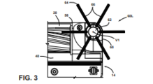
a FIG. 3 é uma vista ampliada de uma porção da FIG. 2, ilustrando uma escova de limpeza de borda no fundo da base;
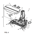
a FIG. 4 é uma vista em perspectiva da base, com uma cobertura superior das coberturas de engrenagem de base e superior para acoplamento de acionamentos das escovas de limpeza de borda explodida para mostrar componentes internos da base;
a FIG. 5 é uma vista em perspectiva ampliada de uma porção da base, com a cobertura superior e cobertura de engrenagem superior removidas para mostrar um acoplamento de acionamento de rolo de escova e um acoplamento de acionamento de escova de limpeza de borda;
a FIG. 6 é uma vista explodida do acoplamento de acionamento de rolo de escova e acoplamento de acionamento de escova de limpeza de borda da FIG. 5;
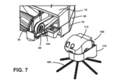
a FIG. 7 é uma vista explodida ilustrando um unidade modular compreendendo o acoplamento de acionamento de escova de limpeza de borda da FIG. 6 e a escova de limpeza de borda;
a FIG. 8 é uma vista em perspectiva traseira mostrando a unidade modular da FIG. 7;
a FIG. 9 é uma vista em corte feita pela linha IX-IX da FIG. XX, ilustrando uma outra escova de limpeza de borda conectada de forma acionada ao rolo de escova;
a FIG. 10 é uma vista de topo de uma outra modalidade de uma escova de limpeza de borda;
a FIG. 11 é uma vista em perspectiva da escova de limpeza de borda da FIG. 10 em uma superfície a ser limpa, ilustrando o cubo tensor aplicando força descendente no instrumento de limpeza;
a FIG. 12 é uma vista explodida da escova de limpeza de borda da FIG. 10;
a FIG. 13 é uma vista em perspectiva de um cubo tensor para a escova de limpeza de borda da FIG. 10;
a FIG. 14 é uma vista em perspectiva ampliada de uma porção da escova de limpeza de borda da FIG. 10;
a FIG. 15 é uma vista de topo ampliada de uma porção da escova de limpeza de borda da FIG. 10;
a FIG. 16 é uma vista de topo de ainda uma outra modalidade de uma escova de limpeza de borda;
a FIG. 17 é uma vista em perspectiva da escova de limpeza de borda da FIG. 16 em uma superfície a ser limpa, ilustrando o cubo tensor aplicando força descendente no instrumento de limpeza;
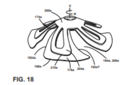
a FIG. 18 é uma vista em perspectiva da escova de limpeza de borda da FIG. 16, com um cubo de fixação removido para ilustrar um cubo tensor afixado a um instrumento de limpeza;
a FIG. 19 é uma vista de topo de ainda uma outra modalidade de uma escova de limpeza de borda;
a FIG. 20 é uma vista de topo em perspectiva de uma modalidade adicional de uma escova de limpeza de borda;
a FIG. 21 é uma vista de baixo da escova de limpeza de borda da FIG. 20;
a FIG. 22 é uma vista explodida da escova de limpeza de borda da FIG. 20;
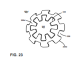
a FIG. 23 é uma vista de topo em perspectiva de ainda uma outra modalidade de um cubo tensor para uma escova de limpeza de borda; e
a FIG. 24 é uma vista de topo em perspectiva de ainda uma outra modalidade de um cubo tensor e corpo rotacional para uma escova de limpeza de borda.[008] In the drawings:
FIG. 1 is a schematic view of a floor cleaner including one or more edge cleaning brushes in accordance with various aspects described herein;
FIG. 2 is a bottom view of a base of the floor cleaner of FIG. 1;
FIG. 3 is an enlarged view of a portion of FIG. 2, illustrating an edge cleaning brush at the bottom of the base;
FIG. 4 is a perspective view of the base, with an upper cover of the base and upper gear covers for coupling exploded edge cleaning brush drives to show internal components of the base;
FIG. 5 is an enlarged perspective view of a portion of the base, with the top cover and top gear cover removed to show a brush roller drive coupling and an edge cleaning brush drive coupling;
FIG. 6 is an exploded view of the brush roller drive coupling and edge cleaning brush drive coupling of FIG. 5;
FIG. 7 is an exploded view illustrating a modular unit comprising the edge cleaning brush drive coupling of FIG. 6 and the edge cleaning brush;
FIG. 8 is a rear perspective view showing the modular unit of FIG. 7;
FIG. 9 is a sectional view taken along line IX-IX of FIG. XX, illustrating another edge cleaning brush actuatedly connected to the brush roller;
FIG. 10 is a top view of another embodiment of an edge cleaning brush;
FIG. 11 is a perspective view of the edge cleaning brush of FIG. 10 on a surface to be cleaned, illustrating the tension hub applying downward force to the cleaning instrument;
FIG. 12 is an exploded view of the edge cleaning brush of FIG. 10;
FIG. 13 is a perspective view of a tension hub for the edge cleaning brush of FIG. 10;
FIG. 14 is an enlarged perspective view of a portion of the edge cleaning brush of FIG. 10;
FIG. 15 is an enlarged top view of a portion of the edge cleaning brush of FIG. 10;
FIG. 16 is a top view of yet another embodiment of an edge cleaning brush;
FIG. 17 is a perspective view of the edge cleaning brush of FIG. 16 on a surface to be cleaned, illustrating the tension hub applying downward force to the cleaning instrument;
FIG. 18 is a perspective view of the edge cleaning brush of FIG. 16, with an attachment hub removed to illustrate a tensioner hub attached to a cleaning implement;
FIG. 19 is a top view of yet another embodiment of an edge cleaning brush;
FIG. 20 is a top perspective view of a further embodiment of an edge cleaning brush;
FIG. 21 is a bottom view of the edge cleaning brush of FIG. 20;
FIG. 22 is an exploded view of the edge cleaning brush of FIG. 20;
FIG. 23 is a top perspective view of yet another embodiment of a tension hub for an edge cleaning brush; and
FIG. 24 is a top perspective view of yet another embodiment of a tension hub and rotational body for an edge cleaning brush.
[009] A descrição no geral se refere a escovas para aparelho de limpeza de superfície que limpam superfícies de piso, incluindo pisos descobertos tais como madeira dura, azulejo e pedra, e superfícies macias tais como tapetes e capachos. Várias modalidades de uma escova de limpeza de borda são descritas a seguir. Como pode-se perceber pela descrição aqui, a escova de limpeza de borda pode ter múltiplas aplicações, mas é, em geral, provida em um alojamento de um limpador de piso que é adaptado para mover sobre uma superfície a ser limpa, a escova de limpeza de borda localizada no alojamento em uma posição para limpar espaços difíceis de alcançar tais como ao longo de bordas e em cantos de uma sala, incluindo bordas ou cantos criados por paredes, rodapés, armários, móveis, etc. Pelo menos algumas modalidades da escova de limpeza de borda provida aqui com um elemento de tensão que aplica força descendente em um instrumento de limpeza em contato com uma superfície a ser limpa. Em um outro aspecto, sistemas de acionamento para escovas de limpeza de borda são descritos a seguir.[009] The general description refers to brushes for surface cleaners that clean floor surfaces, including bare floors such as hardwood, tile and stone, and soft surfaces such as rugs and rugs. Various modalities of an edge cleaning brush are described below. As can be seen from the description here, the edge cleaning brush can have multiple applications, but is generally provided in a floor cleaner housing that is adapted to move over a surface to be cleaned, the floor cleaning brush. edge cleaning located in the housing in a position to clean hard to reach spaces such as along edges and in corners of a room, including edges or corners created by walls, baseboards, cabinets, furniture, etc. At least some embodiments of the edge cleaning brush provided here with a tension element which applies downward force on a cleaning instrument in contact with a surface to be cleaned. In another aspect, drive systems for edge cleaning brushes are described below.
[0010] Os sistemas funcionais do aparelho de limpeza de superfície podem ser arranjados em qualquer configuração desejada, tal como um dispositivo vertical tendo uma base e um corpo vertical para direcionar a base através da superfície a ser limpa. Outras configurações incluem um dispositivo de recipiente tendo uma ferramenta de limpeza conectada a uma base com rodas por uma mangueira a vácuo, um dispositivo portátil adaptado para ser carregado à mão por um usuário para limpeza de áreas relativamente pequenas, um dispositivo autônomo ou robótico, ou um dispositivo comercial. Qualquer dos limpadores supramencionados pode ser adaptado para incluir uma mangueira a vácuo flexível, que pode formar uma porção do conduto de ar de trabalho entre um bocal e a fonte de sucção. Qualquer dos limpadores supramencionados pode ser adaptado para operação sem cabo ou com cabo, opcionalmente incluindo uma bateria interna para operação sem cabo.[0010] The functional systems of the surface cleaning apparatus can be arranged in any desired configuration, such as a vertical device having a base and a vertical body for directing the base across the surface to be cleaned. Other configurations include a container device having a cleaning tool connected to a wheeled base by a vacuum hose, a portable device adapted to be carried by hand by a user for cleaning relatively small areas, a standalone or robotic device, or a commercial device. Any of the aforementioned cleaners can be adapted to include a flexible vacuum hose, which can form a portion of the working air conduit between a mouthpiece and the suction source. Any of the aforementioned cleaners can be adapted for cordless or cordless operation, optionally including an internal battery for cordless operation.
[0011] Em uma modalidade, o aparelho de limpeza de superfície pode ser um aspirador de pó incluindo pelo menos um sistema de coleta a vácuo para criar um vácuo parcial para succionar detritos de uma superfície do piso e coletar os detritos removidos em um espaço provido no aparelho para disposição posterior. O termo “detritos” engloba sujeira, poeira, solo, cabelo, manchas e outros detritos, a menos que de outra forma notado.[0011] In one embodiment, the surface cleaning apparatus may be a vacuum cleaner including at least one vacuum collection system to create a partial vacuum to draw debris from a floor surface and collect the debris removed in a space provided. on the device for later disposal. The term "debris" encompasses dirt, dust, soil, hair, stains and other debris unless otherwise noted.
[0012] Em uma outra modalidade, o aparelho de limpeza de superfície pode ser um varredor incluindo um sistema de varredura para remover detritos secos da superfície a ser limpa, sem o uso de sucção, e coletar os detritos removidos em um espaço provido no aparelho para posterior disposição.[0012] In another embodiment, the surface cleaning apparatus may be a sweeper including a sweeping system to remove dry debris from the surface to be cleaned, without the use of suction, and collect the removed debris in a space provided in the apparatus for later disposal.
[0013] Em ainda uma outra modalidade, o aparelho de limpeza de superfície pode ser um limpador por extração ou limpador profundo, e pode incluir um sistema de entrega de fluido para armazenar fluido de limpeza e entregar o fluido de limpeza na superfície a ser limpa e um sistema de recuperação de fluido para remover o fluido de limpeza e detritos da superfície a ser limpa e armazenar o fluido de limpeza recuperado e detritos. O sistema de entrega de fluido pode ser configurado para entregar líquido, vapor d’água, névoa, ou vapor na superfície a ser limpa.[0013] In yet another embodiment, the surface cleaning apparatus may be an extract cleaner or deep cleaner, and may include a fluid delivery system to store cleaning fluid and deliver the cleaning fluid to the surface to be cleaned. and a fluid recovery system for removing the cleaning fluid and debris from the surface to be cleaned and storing the recovered cleaning fluid and debris. The fluid delivery system can be configured to deliver liquid, water vapor, mist, or vapor to the surface to be cleaned.
[0014] Em ainda uma outra modalidade, o aparelho de limpeza de superfície pode ser um aparelho de esfregar ou varrer úmido, incluindo um sistema de entrega de fluido para armazenar fluido de limpeza e entregar o fluido de limpeza na superfície a ser limpa e um sistema de esfregão ou varredura para remover fluido de limpeza e detritos da superfície a ser limpa sem o uso de sucção. O sistema de entrega de fluido pode ser configurado para entregar líquido, vapor d’água, névoa ou vapor na superfície a ser limpa.[0014] In yet another embodiment, the surface cleaning apparatus may be a wet scrubbing or sweeping apparatus, including a fluid delivery system for storing cleaning fluid and delivering the cleaning fluid to the surface to be cleaned and a mop or sweep system to remove cleaning fluid and debris from the surface to be cleaned without the use of suction. The fluid delivery system can be configured to deliver liquid, water vapor, mist or vapor to the surface to be cleaned.
[0015] A FIG. 1 é uma vista em perspectiva de uma porção de um aparelho de limpeza de superfície de acordo com um aspecto da presente descrição, mostrado como um aparelho de limpeza de piso vertical e, mais especificamente, um aspirador de pó vertical, e no geral designado por 10. Como discutido em detalhe adicional a seguir, o aspirador de pó 10 é provido com várias recursos e melhorias, incluindo pelo menos uma escova de limpeza de borda 60, descrita em detalhe adicional a seguir. Pelo menos uma escova de limpeza de borda 60 pode limpar espaços difíceis de alcançar tal como ao longo de bordas e em cantos de um sala, incluindo bordas ou cantos criados pelas paredes, rodapés, armários, móveis, etc. Como ilustrado aqui, o aspirador de pó 10 tem um alojamento que inclui um conjunto de cabo vertical ou corpo 12 e um pé de limpeza ou base 14 montada em ou acoplada ao corpo vertical 12 e adaptada para movimento através de uma superfície a ser limpa. O aspirador de pó 10 inclui um sistema de coleta a vácuo, que é descrito em detalhe adicional a seguir, e que pode incluir componentes suportados em qualquer ou ambos do corpo 12 e da base 14.[0015] FIG. 1 is a perspective view of a portion of a surface cleaning apparatus in accordance with an aspect of the present description, shown as a vertical floor cleaning apparatus and, more specifically, a vertical vacuum cleaner, and generally referred to as an upright vacuum cleaner. 10. As discussed in further detail below, the vacuum cleaner 10 is provided with various features and improvements, including at least one edge cleaning brush 60, described in further detail below. At least one edge cleaning brush 60 can clean hard-to-reach spaces such as along edges and in corners of a room, including edges or corners created by walls, baseboards, cabinets, furniture, etc. As illustrated herein, vacuum cleaner 10 has a housing that includes a vertical handle assembly or body 12 and a cleaning foot or base 14 mounted to or coupled to vertical body 12 and adapted for movement across a surface to be cleaned. The vacuum cleaner 10 includes a vacuum collection system, which is described in further detail below, and which may include components supported on either or both of the body 12 and the base 14.
[0016] Para efeitos de descrição relacionada às figuras, os termos “superior”, “inferior”, “direita”, “esquerda”, “traseira”, “frente”, “vertical”, “horizontal”, “interno”, “externo” e derivados dos mesmos devem se referir à descrição orientados na FIG. 1 da perspectiva de um usuário detrás do aspirador de pó 10, que define a traseira do aspirador de pó 10. Entretanto, deve-se entender que a descrição pode assumir várias orientações alternativas, exceto onde expressamente especificado ao contrário.[0016] For the purposes of description related to the figures, the terms "top", "bottom", "right", "left", "rear", "front", "vertical", "horizontal", "internal", " external” and derivatives thereof shall refer to the description oriented in FIG. 1 from a user's perspective behind the vacuum cleaner 10, which defines the rear of the vacuum cleaner 10. However, it should be understood that the description may take several alternative orientations, except where expressly specified otherwise.
[0017] O corpo vertical 12 pode compreender qualquer tipo de cabo ou corpo alongado adequado para os propósitos descritos aqui e pode compreender um cabo ou ser de outra forma configurado para um usuário manobrar o aspirador de pó 10 sobre uma superfície a ser limpa. O corpo vertical 12 pode ser adaptado para pivotar em torno de um ou mais eixos geométricos em uma faixa de ângulos relativos à superfície a ser limpa. Opcionalmente, o corpo vertical 12 pode ser configurado de maneira a articular em torno de seu eixo geométrico longitudinal além de pivotar em relação à base 14.[0017] The vertical body 12 may comprise any type of handle or elongate body suitable for the purposes described herein and may comprise a handle or be otherwise configured for a user to maneuver the vacuum cleaner 10 over a surface to be cleaned. The vertical body 12 can be adapted to pivot about one or more geometric axes at a range of angles relative to the surface to be cleaned. Optionally, the vertical body 12 can be configured so as to pivot around its longitudinal geometric axis in addition to pivoting with respect to the base 14.
[0018] Com referência adicional à FIG. 2, o sistema de coleta a vácuo pode incluir um trajeto de ar de trabalho ou caminho de recuperação através do alojamento, incluindo um ou ambos do corpo 12 e da base 14. O caminho de recuperação pode incluir pelo menos uma entrada de sujeira 16 e uma saída de ar limpo 18. O caminho pode ser formado, entre outros elementos, por um bocal de sucção 20 que define a entrada de sujeira, uma fonte de sucção 22 em comunicação fluídica com o bocal de sucção 20 para gerar uma corrente de ar de trabalho, um coletor de detritos 24 para coletar detritos da corrente de ar de trabalho para posterior disposição, e pelo menos um suspiro de escape 26 que define a saída de ar limpo 18.[0018] With further reference to FIG. 2, the vacuum collection system may include a working air path or recovery path through the housing, including one or both of the body 12 and base 14. The recovery path may include at least one dirt inlet 16 and a clean air outlet 18. The path may be formed, among other elements, by a suction nozzle 20 defining the dirt inlet, a suction source 22 in fluid communication with the suction nozzle 20 to generate a stream of air. of working air, a debris collector 24 for collecting debris from the working air stream for further disposal, and at least one exhaust vent 26 defining the clean air outlet 18.
[0019] A fonte de sucção 22, que pode ser um conjunto de motor/ventoinha incluindo um motor de vácuo 28 e uma ventoinha 30, é provida em comunicação fluídica com o coletor 24. O conjunto de motor/ventoinha 22 pode ficar fluidicamente à montante da saída de ar, e pode definir uma porção do trajeto de ar de trabalho. O conjunto de motor/ventoinha 22 pode ser posicionado à jusante do coletor 24 no caminho de recuperação. Em outras modalidades, o conjunto de motor/ventoinha 22 pode estar localizado fluidicamente à montante do coletor 24.[0019] The suction source 22, which may be a motor/fan assembly including a vacuum motor 28 and a fan 30, is provided in fluid communication with the manifold 24. The motor/fan assembly 22 can be fluidly connected to the air outlet amount, and can define a portion of the working air path. Motor/fan assembly 22 can be positioned downstream of manifold 24 in the recovery path. In other embodiments, motor/fan assembly 22 may be fluidly located upstream of manifold 24.
[0020] O coletor 24 pode também definir uma porção do trajeto de ar de trabalho e pode compreender um separador (não mostrado) para separar detritos da corrente de ar de trabalho. Alguns exemplos não limitantes do separador incluem pelo menos um separador ciclônico ou centrífugo, tela de filtro, filtro de espuma, filtro HEPA, saco de filtro flexível e permeável ao ar, ou combinações dos mesmos.The collector 24 may also define a portion of the working air path and may comprise a separator (not shown) for separating debris from the working air stream. Some non-limiting examples of the separator include at least one cyclonic or centrifugal separator, filter cloth, foam filter, HEPA filter, flexible and air permeable filter bag, or combinations thereof.
[0021] O sistema de coleta pode também ser provido com um ou mais filtros adicionais à montante ou à jusante da fonte de sucção 22. Por exemplo, na modalidade ilustrada, um pré-filtro do motor 32 é provido no caminho de recuperação à jusante do coletor e à montante da fonte de sucção 22. Um pós-filtro do motor 34 pode ser provido no caminho de recuperação à jusante da fonte de sucção 22 e à montante da saída de ar limpo 18. O sistema de coleta pode adicionalmente incluir vários condutos, dutos ou os para comunicação fluídica entre os vários componentes do sistema de coleta a vácuo.[0021] The collection system can also be provided with one or more additional filters upstream or downstream of the suction source 22. For example, in the illustrated embodiment, a pre-filter of the engine 32 is provided in the downstream recovery path of the manifold and upstream of the suction source 22. A motor afterfilter 34 may be provided in the recovery path downstream of the suction source 22 and upstream of the clean air outlet 18. The collection system may additionally include several conduits, ducts or those for fluid communication between the various components of the vacuum collection system.
[0022] Referindo-se à FIG. 2, o bocal de sucção 20 pode ser provido na base 14 pode ser adaptado para ficar adjacente à superfície a ser limpa à medida que a base 14 move através de uma superfície. Um rolo de escova 36 ou outro agitador pode ser provido adjacente ao bocal de sucção 20 para agitar a superfície a ser limpa de forma que os detritos sejam mais facilmente ingeridos no bocal de sucção 20. O bocal de sucção 20 mostrado aqui é posicionado para confrontar a superfície a ser limpa para remover detritos da superfície. Em outras modalidades, o bocal de sucção 20 pode ser posicionado em proximidade imediata com o rolo de escova 36 para coletar detritos diretamente do rolo de escova 36.[0022] Referring to FIG. 2, suction nozzle 20 may be provided on base 14 may be adapted to be adjacent to the surface to be cleaned as base 14 moves across a surface. A
[0023] Na modalidade 60L, 60R mostrada aqui, o bocal de sucção 20 é provido entre duas escovas de limpeza de borda 60L, 60R. Em outras modalidades, o bocal de sucção 20 pode ser provido para trás das escovas de limpeza de borda 60L, 60R. De qualquer maneira, as escovas de limpeza de borda 60L, 60R podem varrer detritos sob a base 14 e para o bocal de sucção 20.[0023] In the 60L, 60R mode shown here, the suction nozzle 20 is provided between two edge cleaning brushes 60L, 60R. In other embodiments, suction nozzle 20 may be provided behind edge cleaning brushes 60L, 60R. Either way, the 60L, 60R Edge Cleaning Brushes can sweep debris under the base 14 and into the suction nozzle 20.
[0024] O aspirador de pó 10 pode incluir uma câmara de escova 38 na qual o rolo de escova 36 é montado. O rolo de escova 36 é montado para rotação em torno de um eixo geométrico substancialmente horizontal X, relativo à superfície na qual a base 14 move. O bocal de sucção 20 pode ser formado em um lado inferior da câmara de escova 38. As escovas de limpeza de borda 60L, 60R podem estar localizadas para fora dos lados ou extremidades laterais da câmara de escova 38[0024] The vacuum cleaner 10 may include a brush chamber 38 in which the
[0025] No presente exemplo, o rolo de escova 36 pode ser um rolo de escova sem cerdas ou rolete. O rolo de escova 36 mostrado na FIG. 2 compreende um núcleo 42 e uma pluralidade de paletas chevron 44 que se estendem a partir do núcleo 42, embora uma variedade de diferentes formatos de paleta possam ser usados. As paletas 44 podem ser integralmente formadas com o núcleo 42, tal como por moldagem por injeção, fabricação aditiva, ou um outro processo adequado. O núcleo 42 e as paletas 44 podem ser construídos de um material polimérico tais como acrilonitrila butadieno estireno (ABS), polipropileno ou estireno, ou qualquer outro material adequado tais como plástico, madeira ou metal.[0025] In the present example, the
[0026] Outras modalidades do rolo de escova 36 são possíveis. Por exemplo, o rolo de escova 36 pode compreender cerdas tufadas ou material macio e compressível, tal como microfibra. Em ainda outras modalidades, o rolo de escova 36 pode compreender fibra de náilon, espuma, lâminas e pás elastoméricas. Adicionalmente, embora um rolo de escova que roda horizontalmente simples 36 esteja mostrado aqui, em algumas modalidades, rolos de escovas que rodam horizontalmente duplos podem ser providos no aspirador de pó 10.[0026] Other embodiments of the
[0027] Em uma outra modalidade, o rolo de escova 36 pode ser um rolo de escova híbrido adequado para uso tanto em superfícies duras quanto macias, e para limpeza a vácuo úmida ou a seco. Um rolo de escova híbrido como esse pode incluir uma combinação de cerdas e microfibra. Um exemplo de um rolo de escova híbrido adequado é descrito na Patente dos Estados Unidos Nº. 10.092.155, publicada em 9 de outubro de 2018, que está aqui incorporada por referência em sua íntegra.[0027] In another embodiment, the
[0028] O bocal de sucção 20 pode ficar em comunicação fluídica com o coletor 24 através de um conduto 46. Em modalidades onde o coletor 24 está localizado no corpo vertical 12, o conduto 46 pode passar através do conjunto de união entre a base 14 e o corpo vertical 12, e pode ser flexível para acomodar o movimento do corpo vertical 12 relativo à base 14.[0028] The suction nozzle 20 can be in fluid communication with the collector 24 through a conduit 46. In arrangements where the collector 24 is located in the vertical body 12, the conduit 46 can pass through the joint assembly between the base 14 and vertical body 12, and may be flexible to accommodate movement of vertical body 12 relative to base 14.
[0029] A base 14 pode incluir um alojamento de base 48 que suporta pelo menos alguns dos componentes do sistema de coleta, tais como o rolo de escova 36 e as escovas de limpeza de borda 60L, 60R na modalidade mostrada aqui. Um par de rodas 50 pode ser afixado ao alojamento de base 48 para mover o aspirador de pó 10 sobre a superfície a ser limpa. As rodas 50 podem ser providas na porção traseira do alojamento de base 48, para trás de componentes tais como o bocal de sucção 20, o rolo de escova 36, as escovas de limpeza de borda 60L, 60R, ou qualquer combinação dos mesmos. Um segundo par de rodas 52 pode ser afixado ao alojamento de base 48, para frente do primeiro par de rodas 50.[0029] The base 14 may include a base housing 48 that supports at least some of the collection system components, such as the
[0030] O aspirador de pó 10 mostrado inclui duas escovas de limpeza de borda 60L, 60R no lado inferior 54 da base 14, por exemplo, em um lado inferior do alojamento de base 48. As escovas de limpeza de borda 60L, 60R são montadas para rotação em torno de um eixo geométrico rotacional substancialmente vertical V1, V2, respectivamente, em relação à superfície na qual a base 14 move. Sendo substancialmente vertical, o eixo geométrico rotacional V1, V2 pode desviar até 5 graus da vertical, até 10 graus da vertical, até 20 graus da vertical, ou até 45 graus da vertical. Em algumas modalidades, o eixo geométrico rotacional V1, V2 é configurado para maximizar a área de contato entre a escova de limpeza de borda 60L, 60R e a superfície a ser limpa. Na presente modalidade, duas escovas de limpeza de borda 60L, 60R são providas, e arranjadas em lados laterais opostos, isto é, lados esquerdo e direito, da base 14, de forma que o aspirador de pó 10 possa limpar a borda em qualquer lado da base 14 sem mudar a orientação da base 14. Em outras modalidades, apenas uma escova de limpeza de borda 60 é provida.[0030] The vacuum cleaner 10 shown includes two edge cleaning brushes 60L, 60R on the underside 54 of the base 14, for example, on an underside of the base housing 48. The edge cleaning brushes 60L, 60R are mounted for rotation about a substantially vertical rotational axis V1, V2, respectively, relative to the surface on which the base 14 moves. Being substantially vertical, the rotational geometry axis V1, V2 can deviate up to 5 degrees from the vertical, up to 10 degrees from the vertical, up to 20 degrees from the vertical, or up to 45 degrees from the vertical. In some embodiments, the rotational geometry axis V1, V2 is configured to maximize the contact area between the edge cleaning brush 60L, 60R and the surface to be cleaned. In the present embodiment, two edge cleaning brushes 60L, 60R are provided, and arranged on opposite side sides, i.e., left and right sides, of the base 14, so that the vacuum cleaner 10 can clean the edge on either side of base 14 without changing the orientation of base 14. In other embodiments, only an edge cleaning brush 60 is provided.
[0031] Vantajosamente, as escovas de limpeza de borda 60L, 60R varrem detritos sob a base 14 e para o bocal de sucção 20. A direção de rotação para cada escova de limpeza de borda 60L, 60R é indicada na FIG. 3 pelas setas R1 e R2. Como é ilustrado na FIG. 2, as escovas de limpeza de borda 60L, 60R podem contrarrotacionar de maneira tal que detritos sejam varridos para o bocal de sucção 20 por ambas as escovas 60L, 60R, e a fonte de sucção 22 possa transportar os detritos para o coletor 24. A escova de limpeza de borda do lado esquerdo 60L roda no sentido horário R1 vista por baixo. A escova de limpeza de borda do lado direito 60R roda no sentido anti-horário R2 vista por baixo. Em um exemplo, pelo menos uma porção das escovas de limpeza de borda 60L, 60R 60 se estende além de uma periferia do alojamento de base 48 de maneira tal que detritos adjacentes à base 14 do aspirador de pó 10 podem ser varridos para o bocal de sucção 20. Na modalidade mostrada aqui, as escovas de limpeza de borda 60L, 60R são montadas em uma extremidade dianteira ou de avanço 56 da base 14, para a frente do bocal de sucção 20, e varrer detritos para o centro e traseira da base 14, isto é, para o bocal de sucção 20. As escovas de limpeza de borda 60L, 60R são também montadas para frente do eixo geométrico X do rolo de escova 36, e varrem detritos para o rolo de escova 36 o que pode ajudar na coleta dos detritos. Em outras modalidades, as escovas de limpeza de borda 60L, 60R podem ser montadas em uma outra localização na base 14, ao longo apenas do lado esquerdo da base 14, ou ao longo apenas do lado direito da base 14.[0031] Advantageously, edge cleaning brushes 60L, 60R sweep debris under base 14 and into suction nozzle 20. The direction of rotation for each edge cleaning brush 60L, 60R is indicated in FIG. 3 by arrows R1 and R2. As illustrated in FIG. 2, edge cleaning brushes 60L, 60R can counter-rotate in such a way that debris is swept into suction nozzle 20 by both brushes 60L, 60R, and suction source 22 can transport debris to collector 24. 60L left side edge cleaning brush rotates clockwise R1 seen from below. Right-hand edge cleaning brush 60R rotates counterclockwise R2 seen from below. In one example, at least a portion of the edge cleaning brushes 60L, 60R 60 extend beyond a periphery of the base housing 48 such that debris adjacent to the base 14 of the vacuum cleaner 10 can be swept into the nozzle. suction 20. In the embodiment shown here, edge cleaning brushes 60L, 60R are mounted on a forward or forward end 56 of base 14, forward of suction nozzle 20, and sweep debris to center and rear of base. 14, i.e., to suction nozzle 20. Edge cleaning brushes 60L, 60R are also mounted to the front of the X axis of
[0032] Em outras modalidades do aparelho 10, o sistema de coleta pode ser configurado como um sistema de coleta de varredura ou mecânico que coleta mecanicamente detritos e líquido sem o uso de sucção, tal como pela ação do rolo de escova 36 e escovas de limpeza de borda 60L, 60R impulsionando mecanicamente os detritos diretamente para o coletor 24. Em uma modalidade como essa, as escovas de limpeza de borda 60L, 60R podem varrer detritos sob a base 14 e para uma entrada de detritos na base 14.[0032] In other embodiments of apparatus 10, the collection system can be configured as a sweeping or mechanical collection system that mechanically collects debris and liquid without the use of suction, such as by the action of
[0033] Em ainda um outro mecanismo de coleta alternativo ou adicional, o aparelho 10 pode incluir um conjunto de esfregão ou remoção de poeira para remover detritos úmidos da superfície a ser limpa. Um conjunto de esfregão ou remoção de poeira como esse pode opcionalmente incluir pelo menos uma almofada de esfregão ou remoção de poeira e uma ou mais escovas de limpeza de borda 60L, 60R que podem varrer detritos sob a base 14 e para a almofada. A almofada pode ser estacionária ou rotacionável.[0033] In yet another alternative or additional collection mechanism, the apparatus 10 may include a mop or dust removal assembly to remove wet debris from the surface to be cleaned. Such a mop or dust removal assembly may optionally include at least one mop or dust removal pad and one or more edge cleaning brushes 60L, 60R that can sweep debris under the base 14 and onto the pad. The cushion can be stationary or rotatable.
[0034] A escova de limpeza de borda 60L, 60R pode compreender um ou mais diferentes instrumentos de agitação ou limpeza configurados para escovar, varrer, remover poeira, esfregar, ou senão mover detritos na superfície a ser limpa. Alguns exemplos não limitantes de instrumentos de limpeza para a escova de limpeza de borda 60L, 60R compreendem lâminas, cerdas, pás, lâminas, abas, material de microfibra, pano, almofadas de remoção de poeira, e similares.[0034] Edge cleaning brush 60L, 60R may comprise one or more different stirring or cleaning instruments configured to brush, sweep, remove dust, scrub, or otherwise move debris on the surface to be cleaned. Some non-limiting examples of cleaning instruments for the 60L, 60R Edge Cleaning Brush comprise blades, bristles, paddles, blades, flaps, microfiber material, cloth, dusting pads, and the like.
[0035] A modalidade da escova de limpeza de borda 60L mostrada na FIG. 3 inclui um corpo rotacional 62 configurado para rodar com relação ao alojamento de base 48 e um instrumento de limpeza 64 acoplado ao corpo rotacional 62 para rotação com o mesmo. Ao ser “acoplado ao(à)” corpo rotacional 62, o instrumento de limpeza 64 pode ser afixado a, formado com, ou senão adequadamente unido ao corpo rotacional 62 para rotação com o mesmo. O instrumento de limpeza 64 pode ser configurado para escovar, varrer, remover poeira, esfregar, ou senão mover detritos na superfície a ser limpa. Como discutido aqui, o instrumento de limpeza 64 pode mover detritos na superfície a ser limpa para o bocal de sucção 20 ou outra entrada de detritos no alojamento 48.[0035] The 60L edge cleaning brush embodiment shown in FIG. 3 includes a rotational body 62 configured to rotate with respect to the base housing 48 and a cleaning instrument 64 coupled to the rotational body 62 for rotation therewith. By being "coupled to" rotational body 62, cleaning instrument 64 can be affixed to, formed with, or otherwise suitably joined to rotational body 62 for rotation therewith. The cleaning instrument 64 can be configured to brush, sweep, remove dust, scrub, or otherwise move debris on the surface to be cleaned. As discussed herein, cleaning instrument 64 can move debris on the surface to be cleaned to suction nozzle 20 or other debris inlet in housing 48.
[0036] O instrumento de limpeza 64 pode compreender uma pluralidade de conjuntos de cerdas 66, cada conjunto de cerdas 66 compreendendo uma pluralidade de cerdas. As cerdas podem ser construídas de náilon, tereftalato de polibutileno (PBT), ou qualquer outra fibra sintética ou natural adequada. Os conjuntos de cerdas 66 podem se projetar radialmente a partir do corpo rotacional 62, como mostrado, ou podem se projetar tangencialmente ou em um outro ângulo em outras modalidades.[0036] The cleaning instrument 64 may comprise a plurality of sets of bristles 66, each set of bristles 66 comprising a plurality of bristles. The bristles can be constructed of nylon, polybutylene terephthalate (PBT), or any other suitable synthetic or natural fiber. Bristle assemblies 66 may project radially from rotational body 62, as shown, or may project tangentially or at another angle in other embodiments.
[0037] Porções do instrumento de limpeza 64 podem se projetar além da extremidade dianteira ou de avanço 56 da base 14 e/ou podem se projetar além de um lado lateral 68 da base 14. Por exemplo, as extremidades distais de alguns dos conjuntos de cerdas 66 podem se estender para fora do alojamento de base 48 como mostrado na FIG. 3, incluindo para frente e lateralmente ao alojamento de base 48.[0037] Portions of cleaning instrument 64 may protrude beyond the leading or advancing end 56 of base 14 and/or may protrude beyond a side side 68 of base 14. For example, the distal ends of some of the sets of bristles 66 may extend outwardly from base housing 48 as shown in FIG. 3, including forward and lateral to base housing 48.
[0038] Os comprimentos dos conjuntos de cerdas 66 podem ser iguais uns aos outros, como mostrado, ou conjuntos de cerdas de diferentes comprimentos podem ser providos. Nota-se também que as cerdas em cada conjunto 66 são mostradas tendo o mesmo comprimento, entretanto, em outras modalidades da escova de limpeza de borda 60L, o comprimento de cerdas individuais em um conjunto 66 pode variar.[0038] The lengths of the sets of bristles 66 may be the same as each other, as shown, or sets of bristles of different lengths may be provided. It is also noted that the bristles in each set 66 are shown to have the same length, however, in other embodiments of the edge cleaning brush 60L, the length of individual bristles in a set 66 may vary.
[0039] Os conjuntos de cerdas 66 podem ser igualmente espaçados em torno do eixo geométrico rotacional V1. Por exemplo, na modalidade da escova de limpeza de borda 60L mostrada, o instrumento de limpeza 64 pode compreender seis conjuntos de cerdas 66 que são espaçados aproximadamente 60° um do outro. Outros números de conjuntos de cerdas e espaçamento são possíveis, tais como, mas não limitados a, nove conjuntos de cerdas 66 que são espaçados aproximadamente 40° um do outro. Em ainda uma outra modalidade, em vez de serem arranjadas em conjuntos discretos, as cerdas podem ser arranjadas de forma substancialmente contínua em torno do corpo rotacional 62.[0039] Bristle sets 66 can be equally spaced around the rotational axis V1. For example, in the embodiment of edge cleaning brush 60L shown, cleaning instrument 64 may comprise six sets of bristles 66 that are spaced approximately 60° apart. Other numbers of bristle sets and spacing are possible, such as, but not limited to, nine sets of bristles 66 that are spaced approximately 40° apart. In yet another embodiment, rather than being arranged in discrete assemblies, the bristles may be arranged substantially continuously around the rotational body 62.
[0040] O corpo rotacional 62 pode compreender um cubo configurado para rodar no eixo geométrico rotacional V1. Opcionalmente, o corpo rotacional 62 pode compreender uma superfície periférica que é disposta radialmente para fora do eixo geométrico rotacional V1, e os conjuntos de cerdas 66 podem se projetar radialmente com relação à superfície periférica. Em outras modalidades, os conjuntos de cerdas 66 podem se projetar tangencialmente ou em um outro ângulo a partir da superfície periférica.[0040] The rotational body 62 may comprise a hub configured to rotate on the rotational axis V1. Optionally, the rotational body 62 can comprise a peripheral surface that is disposed radially outward from the rotational geometric axis V1, and the bristle assemblies 66 can project radially with respect to the peripheral surface. In other embodiments, the bristle assemblies 66 may protrude tangentially or at another angle from the peripheral surface.
[0041] Referindo-se à FIG. 4, o alojamento de base 48 pode ser constituído de uma ou mais peças, revestimentos ou alojamentos separados. Em um exemplo não limitante, o alojamento de base 48 pode incluir pelo menos uma cobertura inferior 70 e uma cobertura superior 72 que encerram componentes da base 14 entre os mesmos. A cobertura superior 72 é mostrada explodida da cobertura inferior 70 na FIG. 4.[0041] Referring to FIG. 4, base housing 48 can be comprised of one or more separate pieces, liners, or housings. In a non-limiting example, base housing 48 may include at least a lower cover 70 and an
[0042] Em uma modalidade, o rolo de escova 36 e ambas as escovas de limpeza de borda 60L, 60R podem ser operacionalmente acoplados a e acionados por um conjunto de acionamento incluindo um motor de rolo de escova ou motor de escova 74 na base 14. Alternativamente, o motor de vácuo 28 (FIG. 3) pode prover tanto sucção a vácuo quanto rodar uma ou mais das escovas 36, 60L, 60R. Em uma outra modalidade alternativa, um motor (não mostrado) separado do motor de escova 74 pode ser provido na base 14 para acionar as escovas de limpeza de borda 60L, 60R, com ambas as escovas de limpeza de borda 60L, 60R operacionalmente acopladas a e acionadas pelo motor separado comum. Em ainda uma outra modalidade alternativa, motores individuais (não mostrados) separados do motor de escova 74 podem ser providos na base 15 para acionar cada uma das escovas de limpeza de borda 60L, 60R, com cada escova de limpeza de borda 60L, 60R operacionalmente acoplada a e acionada por um dos motores separados individuais.[0042] In one embodiment, the
[0043] Na modalidade mostrada, o motor de escova 74 é configurado para acionar o rolo de escova 36 em torno do eixo geométrico rotacional X, a primeira escova de limpeza de borda ou do lado esquerdo 60L em torno do eixo geométrico rotacional V1, e a segunda escova de limpeza de borda ou do lado direito 60R em torno do eixo geométrico rotacional V2. Acoplamentos ou transmissões de acionamentos acoplam o motor de escova 74 a cada uma das escovas 36, 60L, 60R. Cada acoplamento de acionamento pode compreender uma ou mais correias, engrenagens, eixos, polias ou combinações dos mesmos.[0043] In the embodiment shown, brush motor 74 is configured to drive
[0044] Os eixos geométricos rotacionais V1, V2 das escovas de limpeza de borda 60L, 60R podem ser dispostos em extremidades opostas do rolo de escova 36. Na modalidade mostrada, os eixos geométricos rotacionais V1, V2 das escovas de limpeza de borda 60L, 60R são espaçado de cada extremidade do rolo de escova 36. Como mostrado em vista de baixo da FIG. 2, os eixos geométricos rotacionais V1, V2 das escovas de limpeza de borda 60L, 60R podem ficar dispostos para frente do eixo geométrico rotacional X. Em outras modalidades, os eixos geométricos rotacionais V1, V2 podem interceptar o eixo geométrico rotacional X.[0044] The rotational geometry axes V1, V2 of the edge cleaning brushes 60L, 60R may be arranged at opposite ends of the
[0045] Os eixos geométricos rotacionais V1, V2 das escovas de limpeza de borda 60L, 60R podem ser substancialmente perpendiculares ao eixo geométrico rotacional X do rolo de escova 36. Sendo substancialmente perpendiculares, os eixos geométricos rotacionais V1, V2 podem desviar até 5 graus da perpendicular, até 10 graus da perpendicular, ou até 20 graus da perpendicular. Os eixos geométricos rotacionais V1, V2 das escovas de limpeza de borda 60L, 60R podem ser paralelos entre si, ou não paralelos.[0045] The rotational geometric axes V1, V2 of the edge cleaning brushes 60L, 60R can be substantially perpendicular to the rotational geometric axis X of the
[0046] Na modalidade mostrada na FIG. 4, o rolo de escova 36 é operacionalmente acoplado a e acionado por um conjunto de acionamento incluindo o motor de escova 74 e um acoplamento ou transmissão de acionamento 76 entre o rolo de escova 36 e o motor de escova 74. A primeira escova de limpeza de borda 60L é operacionalmente acoplada a e acionada por um conjunto de acionamento incluindo o motor de escova 74 e um acoplamento ou transmissão de acionamento 78 entre a escova 60L e o rolo de escova 36. A segunda escova de limpeza de borda 60R é operacionalmente acoplada a e acionada por um conjunto de acionamento incluindo o motor de escova 74 e um acoplamento ou transmissão de acionamento 80 entre a escova 60R e o rolo de escova 36.[0046] In the embodiment shown in FIG. 4,
[0047] Os acoplamento de acionamentos de escova de borda 78, 80 para cada escova de limpeza de borda 60R, 60L podem ser configurados para reduzir a velocidade de acionamento das escovas 60R, 60L, de maneira tal que as escovas de limpeza de borda 60R, 60L movam a menores velocidades que o rolo de escova 36. Se não reduzida, as escovas de limpeza de borda 60R, 60L podem arremessar detritos para fora da base 14 em vez de varrer os detritos para o bocal de sucção 20. Em um exemplo, o rolo de escova 36 é acionado a 314,15 a 458.14 rad/s (3.000 a 4.375 rpm), inclusive, 324,63 a 387,46 rad/s (3.100 a 3.700 rpm), inclusive, e as escovas de limpeza de borda 60R, 60L são acionadas a 11,51 rad/s (110 rpm), alternativamente a 14,13 rad/s (135 rpm), alternativamente a 12,56 a 14,66 rad/s (120 a 140 rpm), inclusive, alternativamente a 15,70 a 18,32 rad/s (150 a 175 rpm).[0047] The 78, 80 edge brush drive couplings for each 60R, 60L edge cleaning brush can be configured to reduce the drive speed of the 60R, 60L brushes such that the 60R edge cleaning brushes , 60L move at slower speeds than
[0048] Referindo-se às FIGS. 5-6, em uma modalidade, o acoplamento de acionamento de rolo de escova 76 pode incluir uma correia de acionamento 82 que engata por atrito uma roda de acionamento 84 acoplada a uma saída do motor de escova 74 e uma roda acionada 86 no rolo de escova 36, e que transmite a força rotacional provida pelo motor 28 ao rolo de escova 36.[0048] Referring to FIGS. 5-6, in one embodiment, the brush roller drive coupling 76 may include a drive belt 82 that frictionally engages a drive wheel 84 coupled to an output of the brush motor 74 and a drive wheel 86 on the roller.
[0049] O acoplamento de acionamento da escova de borda 78 pode incluir uma trem de engrenagem tendo uma engrenagem de entrada acoplada ao rolo de escova 36 ou com a transmissão entre o rolo de escova 36 e o motor de escova 74. Na modalidade mostrada na FIG. 5-6, o trem de engrenagem para a primeira escova de limpeza de borda 60L inclui uma rosca sem fim 90 operacionalmente acoplada ao rolo de escova 36 para rotação com o mesmo, uma engrenagem acionada de dois estágios tendo uma primeira engrenagem ou rosca sem fim 92 enredada com a rosca sem fim 90 e uma segunda engrenagem 94 acoplada à primeira engrenagem 92 para rotação com a mesma, uma correia da escova de borda 96 acoplada à segunda engrenagem 94 para transmitir a força rotacional da engrenagem de dois estágios para uma engrenagem acionada 98. A engrenagem acionada 98 é acoplada à escova de limpeza de borda 60L para acionar a escova 60L para rotação em torno do eixo geométrico V1.[0049] Edge brush drive coupling 78 may include a gear train having an input gear coupled to brush
[0050] A engrenagem acionada 98 pode ser acoplada a um eixo de acionamento 100 da escova de limpeza de borda 60L. A engrenagem acionada 98 produz uma força de acionamento para o eixo de acionamento 100 e roda a uma velocidade predeterminada. O eixo de acionamento 100 pode definir o eixo geométrico de rotação V1 da escova de limpeza de borda 60L. Opcionalmente, o eixo de acionamento 100 pode ser unido a ou senão acoplado ao corpo rotacional 62 (FIG. 3) da escova de limpeza de borda 60L. A escova de limpeza de borda 60L pode ser montada de forma fixa ou removível no eixo de acionamento 100. Com uma montagem removível, a escova de limpeza de borda 60L pode ser um componente de reposição ou de troca para escovas de limpeza de borda existentes em aspiradores de pó e outros dispositivos de limpeza de piso.[0050] Drive gear 98 can be coupled to a
[0051] O trem de engrenagem descrito com relação às FIGS. 5-6 pode reduzir a velocidade rotacional da escova de limpeza de borda 60L em relação ao rolo de escova. Em uma modalidade, a razão de redução de engrenagem da rosca sem fim 90 para a engrenagem acionada 98 pode ser 1:30.[0051] The gear train described with respect to FIGS. 5-6 can reduce the rotational speed of the 60L edge cleaning brush in relation to the brush roller. In one embodiment, the gear reduction ratio of auger 90 to driven gear 98 can be 1:30.
[0052] O trem de engrenagem pode ser acoplado à roda acionada 86 do rolo de escova 36 para acionar a engrenagem da rosca sem fim 90. Na modalidade mostrada na FIG. 6, um membro acionado canelado 102 é acoplado à rosca sem fim 90, e a roda de acionamento 86 do rolo de escova 36 pode compreender um membro de acionamento canelado 104 configurado para corresponder axialmente com o membro acionado canelado 102. Os membros canelados 102, 104 têm dentes, cunhas, ou membros de outros formatos que enredam quando os membros canelados 102, 104 são axialmente engatados. Os membros canelados 102, 104 dessa maneira formam uma conexão canelada entre a rosca sem fim 90 e roda acionada 86 para transferir torque para a rosca sem fim 90. Outros acoplamentos entre o rolo de escova 36 e o trem de engrenagem são possíveis.[0052] The gear train can be coupled to the driven wheel 86 of the
[0053] A configuração de trem de engrenagem descrita com relação às FIGS. 5-6 pode economizar espaço no lado dianteiro da base 14, permitindo que o eixo geométrico rotacional V1 da escova de limpeza de borda 60L fique mais próximo à extremidade dianteira 56 da base 14. Em vez de acionar diretamente a escova 60L por meio da engrenagem da rosca sem fim 90, o uso da correia 96 para acionar indiretamente a escova 60L por meio da engrenagem da rosca sem fim 90 permite que o eixo geométrico rotacional V1 fique disposto mais afastado do eixo geométrico rotacional do rolo de escova X. Em uma modalidade alternativa, a rosca sem fim 90 é acoplada diretamente à engrenagem acionada 98 afixada ao eixo de acionamento 100, com a correia 96 e outras engrenagens 92, 94 não providas.[0053] The gear train configuration described with respect to FIGS. 5-6 can save space on the front side of the base 14 by allowing the rotational geometry axis V1 of the 60L edge cleaning brush to be closer to the front end 56 of the base 14. Instead of directly driving the 60L brush through the gear of worm 90, the use of belt 96 to indirectly drive brush 60L via worm gear 90 allows the rotational axis V1 to be disposed further away from the rotational axis of brush roller X. In one embodiment Alternatively, auger 90 is directly coupled to drive gear 98 affixed to drive
[0054] O acoplamento de acionamento da escova de borda 80 para a outra escova de limpeza de borda 60R pode ser substancialmente similar, exceto que o trem de engrenagem pode ser acoplado com um membro de acionamento canelado 114 na extremidade não acionada do rolo de escova 36 para acionar a engrenagem da rosca sem fim 90. Na modalidade mostrada na FIG. 9, o membro de acionamento canelado 102 acoplado à rosca sem fim 90 pode enredar com o membro de acionamento canelado 114 para transferir torque para a rosca sem fim 90. Outros acoplamentos entre o rolo de escova 36 e o trem de engrenagem são possíveis.[0054] The drive coupling of edge brush 80 to the other edge cleaning brush 60R can be substantially similar, except that the gear train can be coupled with a fluted drive member 114 at the undriven end of the brush roller. 36 to drive the worm gear 90. In the mode shown in FIG. 9, the
[0055] Com referência adicional à FIG. 7, o acoplamento de acionamento da escova de borda 78 pode ser alojado no alojamento de base 48 ou pode ser alojado em uma caixa de engrenagem separada 106 que é formada com ou senão acoplada ao alojamento 48. Para reduzir o ruído e vibração, o trem de engrenagem do acoplamento de acionamento 78 pode estar localizado em uma caixa de engrenagem 106 como um módulo com tolerância mais precisa. A caixa de engrenagem 106 pode incluir uma fenda 108 através da qual o eixo de acionamento 100 se estende para conectar o acoplamento de acionamento 78 à escova de limpeza de borda 60. A caixa de engrenagem para a escova de limpeza de borda 60L, isto é, o acoplamento de acionamento de engrenagem 78 e sua caixa 106, pode ser disposta interna ou externa ao alojamento de base 48, e pode ser removível da base 14. Com uma caixa de engrenagem não removível, uma porção da escova de limpeza de borda 60L, tal como seu instrumento de limpeza, pode ser montado de forma fixa ou removível no eixo de acionamento 100.[0055] With further reference to FIG. 7, the edge brush drive coupling 78 can be housed in base housing 48 or can be housed in a
[0056] A caixa de engrenagem 106 pode ser constituída de uma ou mais peças, caixas ou alojamentos separados. Em um exemplo não limitante, a caixa de engrenagem 106 pode incluir pelo menos um alojamento de engrenagem inferior 110 e uma cobertura de engrenagem superior 112 que encerram componentes do acoplamento de acionamento da escova de borda 78 entre os mesmos. A engrenagem cobertura superior 112 é mostrada explodida do alojamento de engrenagem 110 na FIG. 7.[0056] The
[0057] Em uma modalidade, uma unidade modular compreendendo o acoplamento de acionamento da escova de borda 78, caixa de engrenagem 106, e opcionalmente também compreendendo a escova de limpeza de borda 60L, é montada de forma removível na base 14. Com a unidade modular mostrada nas FIGS. 7-8, o acoplamento de acionamento da escova de borda 78 e a escova de limpeza de borda 60L podem ser simultaneamente montados na base 14 pela afixação da caixa de engrenagem 106 na base 14 para facilidade de montagem com o aspirador de pó 10. Similarmente, o acoplamento de acionamento da escova de borda 78 e a escova de limpeza de borda 60L são simultaneamente removíveis da base 14 pela remoção da caixa de engrenagem 106 da base 14, permitindo limpeza, reparo, ou troca da unidade modular ou componentes da unidade modular. Com uma unidade modular ou caixa de engrenagem, a escova de limpeza de borda 60L pode ser um componente de reposição ou de troca para escovas de limpeza de borda existentes em aspiradores de pó e outros dispositivos de limpeza de piso. Embora a unidade modular esteja mostrada compreendendo o acoplamento de acionamento da escova de borda 78 descrito com relação às FIGS. 5-6, entende-se que outras transmissões de escova de borda são possíveis.[0057] In one embodiment, a modular unit comprising edge brush drive coupling 78,
[0058] Para montar a unidade modular ou caixa de engrenagem com a base 14, a caixa de engrenagem 106 pode ser montada com a cobertura inferior 70, com os membros canelados 102, 104 enredando para acoplar o acoplamento de acionamento 78 com a roda acionada 86 do rolo de escova 36. A caixa de engrenagem 106 pode ser afixada à cobertura inferior 70 usando qualquer método de fixação adequado, tal como usando parafusos ou outros prendedores para montar a caixa de engrenagem 106 na cobertura inferior 70. Após fixação da caixa de engrenagem 106, a cobertura superior 72 (FIG. 4) pode ser montada na cobertura inferior 70. A cobertura superior 72 pode cobrir pelo menos uma porção da caixa de engrenagem 106, como mostrado na FIG. 1.[0058] To assemble the modular unit or gearbox with the base 14, the
[0059] Uma caixa de engrenagem similar 106 para o acoplamento de acionamento do lado direito da escova de borda 80 pode ser provido, como mostrado nas FIGS. 4 e 9. O rolo de escova 36 e a câmara de escova 38 podem ser dispostos entre as duas caixas de engrenagem 106. A cobertura superior 72 pode cobrir pelo menos uma porção de ambas as caixas de engrenagem 106, quando instaladas na cobertura inferior 70.[0059] A
[0060] As FIGS. 10-15 mostram detalhes de uma outra modalidade de uma escova de limpeza de borda, designada no geral por 160. A escova de limpeza de borda 160 pode ser provida no aspirador de pó 10 mostrado nas FIGS. 1-9 no lugar de uma ou ambas as escovas de limpeza de borda 60L, 60R, ou pode ser provida em um outro aparelho de limpeza de superfície para limpar espaços difíceis de alcançar tais como ao longo das bordas e em cantos de um sala, incluindo bordas ou cantos criados pelas paredes, rodapés, armários, móveis, etc. A escova de limpeza de borda 160 pode ser configurada para rodar em torno de um eixo geométrico rotacional substancialmente vertical V.[0060] FIGS. 10-15 show details of another embodiment of an edge cleaning brush, generally designated 160. Edge cleaning
[0061] A escova de limpeza de borda 160 pode incluir um corpo rotacional 162 configurado para rodar com relação ao alojamento de base 48 (FIG. 1), ou outro alojamento de limpador de piso, e um instrumento de limpeza 164 acoplado ao corpo rotacional 162 para rotação com o mesmo. Sendo “acoplado ao(à)” corpo rotacional 162, o instrumento de limpeza 164 pode ser afixado a, formado com, ou senão adequadamente unido ao corpo rotacional 162 para rotação com o mesmo. O instrumento de limpeza 164 pode ser configurado para escovar, varrer, remover poeira, esfregar, ou senão mover detritos na superfície a ser limpa. Como aqui discutido, o instrumento de limpeza 164 pode mover detritos na superfície a ser limpa para o bocal de sucção 20 (FIG. 2) ou outra entrada de detritos em um limpador de piso.[0061]
[0062] A escova de limpeza de borda 160 pode incluir um elemento de tensão, tal como um cubo tensor 166 que aplica força descendente F (vide FIG. 11) no instrumento de limpeza 164 para forçar o instrumento de limpeza 164 contra uma superfície S a ser limpa. O cubo tensor 166 também provê suporte estrutural, que permite que o instrumento de limpeza 164 seja fabricado de materiais e/ou em formatos que podem de outra forma ser muito flexíveis ou delgados para efetivamente mover detritos na superfície a ser limpa para o bocal de sucção 20 (FIG. 2) ou outra entrada de detritos.[0062]
[0063] O cubo tensor 166 pode ser disposto entre o corpo rotacional 162 e o instrumento de limpeza 164. O cubo tensor 166 pode ser montado com o instrumento de limpeza 164 para formar um subconjunto, e o corpo rotacional 162 é subsequentemente montado no subconjunto. Por exemplo, em uma modalidade, o cubo tensor é colado no instrumento de limpeza 164. Em uma outra modalidade, o cubo tensor 166 pode ser integralmente formado com o corpo rotacional 162 para formar um subconjunto, e então subsequentemente afixado ao instrumento de limpeza 164, tal como por união adesiva, estaqueamento térmico, ou sobremoldagem, por exemplo. Em ainda uma outra modalidade, o cubo tensor 166 pode ser sobremoldado no instrumento de limpeza 164 para formar um subconjunto, e o corpo rotacional 162 é subsequentemente montado no subconjunto.[0063] The
[0064] O corpo rotacional 162 pode compreender um cubo de fixação 168 configurado para rodar no eixo geométrico rotacional V. Opcionalmente, o corpo rotacional 162 pode compreender uma superfície periférica 170 que é disposta radialmente para fora do eixo geométrico rotacional V, e o instrumento de limpeza 164 pode se projetar radialmente com relação à superfície periférica 170.[0064] The
[0065] O corpo rotacional 162 pode ser acoplado a um eixo de acionamento, tal como eixo de acionamento 100 (FIG. 6) para rotação da escova de limpeza de borda 160. O cubo de fixação 168 pode ter uma abertura 172 para receber uma extremidade do eixo de acionamento 100. Nota-se que o conjunto de acionamento das FIGS. 5-6 é apenas um exemplo de um conjunto de acionamento para a escova de limpeza de borda 160, e que outros conjuntos de acionamento podem ser usados.[0065]
[0066] O cubo de fixação 168 pode compreender um projeto em duas peças como mostrado na FIG. 12, em que os lados voltados para dentro do cubo de fixação de duas peças 168 são mostrados. As duas peças podem ser separadamente moldadas de plástico, e então montadas juntas antes da montagem com o resto da escova 160. Por exemplo, as duas peças do cubo 168 podem ser presas uma na outra usando um encaixe de pressão em qualquer peça do cubo 168, Alternativamente, o cubo de fixação 168 pode compreender um projeto em peça única que é sobremoldado no cubo de tensão 166 e/ou o instrumento de limpeza 164.[0066] The clamping hub 168 may comprise a two-piece design as shown in FIG. 12, in which the inwardly facing sides of the two-piece clamping hub 168 are shown. The two pieces can be separately molded from plastic, and then assembled together before assembly with the rest of the
[0067] O instrumento de limpeza 164 pode compreender uma almofada com uma porção interna ou central 174 e uma porção externa compreendendo uma pluralidade de dedos 176 que se projetam a partir de uma periferia da porção central 174. A almofada pode ser fabricada por corte em matriz ou um outro método de fabricação adequado, de maneira tal que a porção central 174 e os dedos 176 sejam cortados de uma única peça de material plano. Em outras modalidades, a almofada pode compreender múltiplas peças afixadas, costuradas ou de outra forma unidas entre si.[0067] The
[0068] O instrumento de limpeza 164 pode ser fabricado de pano de microfibra tendo fibras mais finas que um denier e/ou tendo um diâmetro menor que dez micrômetros (µm). O pano de microfibra pode ser feito de poliésteres, poliamidas (por exemplo, náilon), ou uma combinação dos dois. Em uma modalidade específica, o pano de microfibra pode ser um pano microsuede, um pano de poliéster sintético compreendido de milhões de microfibras. Microsuede pode prover captação de poeira superior quando comparado a uma escova com cerdas convencional, particularmente para detritos finos, tais como poeira e talco. Mais especificamente, o instrumento de limpeza 164 pode compreender uma almofada de pano microsuede cortado em matriz. Em outras modalidades, outros tipos de almofadas de varrimento, remoção de poeira ou esfregão podem ser usados.[0068] The
[0069] A porção central 174 pode ser sólida, isto é, sem, ou substancialmente sem, qualquer abertura ou rupturas. Como mostrado na FIG. 12, um furo central 178 e dois furos menores 180 adjacentes ao furo central 178 podem ser providos no instrumento de limpeza 164 para fixação do corpo rotacional 162 à almofada. A porção central 174 da modalidade mostrada é de outra forma sólida.[0069] The
[0070] O cubo tensor 166 pode se estender na porção central 174 do instrumento de limpeza 164. Com uma porção central sólida 174, o instrumento de limpeza 164 se estende continuamente por baixo do cubo tensor 166, com o cubo tensor 166 em engate embutido com o instrumento de limpeza 164. Em outras modalidades, o instrumento de limpeza 164 pode se estender continuamente por baixo do cubo tensor 166, com o cubo tensor 166 em engate embutido com o instrumento de limpeza 164, com uma porção central não sólida, isto é, com uma porção central tendo uma ou mais aberturas ou quebras. Nessas e outras modalidades, o cubo tensor 166 pode ser colado na porção central 174.[0070] The
[0071] A pluralidade de dedos 176 pode se projetar além de uma periferia do cubo tensor 166. Como mostrado na FIG. 10, a porção central 174 pode compreender uma seção anular 182 que se estende além da periferia do cubo tensor 166, com os dedos 176 se estendendo a partir da seção anular 182. Consequentemente, o cubo tensor 166 não se estende sobre os dedos 176 e, em vez disso, engata o instrumento de limpeza 164 para dentro dos dedos 176.[0071] The plurality of
[0072] Os dedos 176 podem se projetar radialmente a partir da porção central 174 como mostrado, ou podem ser curvos. Opcionalmente, com a porção central 174 compreendendo a seção anular 182 que é disposta radialmente para fora do cubo tensor 166, os dedos 176 podem se projetar radialmente a partir da seção anular 182.[0072]
[0073] Os dedos 176 podem ser igualmente espaçados em torno do eixo geométrico rotacional V. Por exemplo, na modalidade da escova de limpeza de borda 160 mostrada, o instrumento de limpeza 164 pode compreender 32 dedos que são espaçados aproximadamente 11,25° um do outro. Outros números e espaçamento para os dedos são possíveis.[0073]
[0074] Com referência às FIGS. 14-15, os dedos 176 podem se estender de uma raiz 184 acoplada à porção central 174 até uma ponta distal ou para fora 186, e ter um lado de topo 188 e um lado de baixo 190. O lado de baixo 190 pressiona a superfície a ser limpa em operação. As pontas 186 podem coletivamente definir a periferia externa 196 do instrumento de limpeza 164. Cada dedo 176 pode ter bordas laterais espaçadas 192 que unem a raiz 184 à ponta 186. O formato, tamanho e espaçamento dos dedos 176 podem ser uniformes, como mostrado. Em ainda outras modalidades, o formato, tamanho e/ou espaçamento de dedos individuais 176 podem ser diferentes.[0074] With reference to FIGS. 14-15,
[0075] Os dedos 176 podem ser separados por fendas 194. As fendas 194 podem se estender radialmente para dentro de uma periferia externa 196 do instrumento de limpeza 164 e definem um lacuna entre as bordas laterais 192 de dedos adjacentes 176. As fendas 194 são abertas na periferia externa 196 e se estendem até as extremidades de fenda 198 dispostas para dentro da periferia externa 196.The
[0076] Os dedos 176 têm um espessura de dedo FT definida como a distância entre os lados de topo e de baixo 188, 190, um comprimento de dedo FL definido como a distância entre a raiz 184 e a ponta 186, e uma largura de dedo FW definida como a distância entre as bordas laterais 192. Os dedos 176 podem ser membros amplos planos, com a espessura FT sendo menor que o comprimento FL ou largura FW. A largura de dedo FW pode ser constante da raiz 184 à ponta 186, ou pode variar, tal como aumentando da raiz 184 para a ponta 186 como mostrado na modalidade ilustrada.
[0077] Cada fenda 194 tem uma largura de fenda SW definida como a distância entre bordas laterais 192 de dedos adjacentes 176 e uma profundidade de fenda SD definida como a distância da periferia externa 196 do instrumento de limpeza 164 até a extremidade 198 da fenda 194. Em uma modalidade, a profundidade de fenda SD pode ser 10 a 20 mm, inclusive, alternativamente 15 mm.[0077] Each
[0078] As pontas 186 dos dedos 176 e as extremidades 198 das fendas 194 que conectam dedos adjacentes 176 podem ser redondas. Outros formatos para os dedos 176 e extremidades das fendas 194 são possíveis, tal como sendo abaulados ou angulados.The tips 186 of the
[0079] Referindo-se à FIG. 13, o cubo tensor 166 pode compreender um porção anular interna ou anel 200 definindo uma abertura central 202 e uma porção externa compreendendo braços tensores 204 que são separados por fendas 206. Os braços 204 podem se estender radialmente para fora do anel 200, como mostrado, ou podem se estender ao longo de uma curva a partir do anel 200. O cubo tensor 166 pode ser em formato de cone para pré-carregar o instrumento de limpeza 164, isto é, exercer força descendente no instrumento de limpeza 164 para forçar o instrumento de limpeza 164 contra a superfície a ser limpa. Outros formatos para pré-carregamento do instrumento de limpeza 164 são possíveis, tal como cubo tensor em formato de domo 166.[0079] Referring to FIG. 13, the
[0080] Cada braço 204 pode se estender de uma primeira extremidade ou raiz 208 afixada ao anel 200 até uma segunda extremidade ou ponta 210, e ter um lado de topo 212 e um lado de baixo 214. O lado de baixo 214 pressiona o instrumento de limpeza 164 quando o cubo tensor 166 é montado com o instrumento de limpeza 164. As pontas 210 podem coletivamente definir uma periferia externa 216 do cubo 166. Cada braço 204 pode ter bordas laterais espaçadas 218 que unem a raiz 208 à ponta 210. As bordas laterais 218 de braços adjacentes 204 são separadas por uma das fendas 206. Os braços 204 podem ser substancialmente sólidos, ou, como mostrado aqui, podem compreender pelo menos uma abertura 220 nos mesmos, que podem aumentar a flexibilidade dos braços 204.[0080] Each
[0081] Os braços 204 podem ser igualmente espaçados em torno do eixo geométrico rotacional V. Por exemplo, na modalidade da escova de limpeza de borda 160 mostrada, o cubo tensor 166 pode compreender oito braços 204 que são espaçados aproximadamente 45° um do outro. Outros números e espaçamento de braços são possíveis.[0081] The
[0082] Os braços 204 têm uma espessura de braço AT definida como a distância entre os lados de topo e de baixo 212, 214, um comprimento de braço AL definido como a distância entre a raiz 208 e a ponta 210, e uma largura de braço AW definida como a distância entre as bordas laterais 218. Os braços 204 podem ser membros planos, com a espessura AT sendo menor que o comprimento AL ou largura AW.
[0083] A largura AW pode ser constante da raiz 208 à ponta 210, ou pode variar, tal como aumentando da raiz 208 para a ponta 210, como mostrado na modalidade ilustrada. Visto de cima, como na FIG. 10, os braços 204 têm o formato geral de um trapézio. Outros formatos de braço são possíveis, tais como, mas sem se limitar a quadrado, retangular, paralelogramo, ou outros formatos poligonais. Em ainda outras modalidades, o comprimento, largura e/ou espessura de braços individuais 204 podem ser diferentes.[0083] The width AW may be constant from root 208 to tip 210, or it may vary, such as increasing from root 208 to tip 210, as shown in the illustrated embodiment. Viewed from above, as in FIG. 10,
[0084] Para o cubo tensor em formato de cone 166 mostrado, o anel 200 pode ser frustocônico, afunilando para baixo a partir da borda interna 222 do anel 200, que forma uma borda de topo do formato de cone e define a abertura central 202, até um borda externa 224 do anel 200, que forma uma borda de baixo do formato de cone. Os braços 204 se estendem a partir da borda externa ou de baixo 224 do anel 200. A borda externa ou de baixo 224 pode definir um plano, e os braços 204 podem ser dispostos abaixo do plano, e podem se estender em uma direção para fora do plano, da raiz 208 à ponta 210, em um ângulo.[0084] For the cone-shaped
[0085] Na modalidade mostrada, o anel 200 é posicionado próximo ao centro do cubo tensor 166, isto é, ele fica dentro da metade interna do raio do cubo tensor 166. Em uma modalidade alternativa, o anel 200 pode ser posicionado ainda mais para fora no raio para aumentar a rigidez e funcionalidade de retenção de forma do instrumento de limpeza 164, tal como ficando dentro da metade externa do raio do cubo tensor 166 ou se estendendo parcialmente da metade interna até a metade externa. A FIG. 23, descrita em detalhe adicional a seguir, mostra uma modalidade alternativa de um cubo tensor 166d para a escova 160.[0085] In the embodiment shown, the
[0086] As fendas 206 se estendem da periferia externa 216 do cubo 166, em direção ao centro do cubo 166. As fendas 206 são abertas na periferia externa 216 e se estendem até as extremidades de fenda 226 dispostas para dentro da periferia externa 216. As fendas 206 permitem flexão individual dos braços 204 para deflexão em superfícies não planas tais como nos acabamento de parede e piso. Em uma modalidade alternativa, o cubo 166 pode ser um sólido ou sem dedos, e pode ser em formato de anel. A FIG. 24, descrita em detalhe adicional a seguir, mostra uma modalidade alternativa de um cubo tensor sólido 166e para a escova 160.The
[0087] As pontas 210 dos braços 204 e as extremidades 226 das fendas 206 podem ser abauladas como mostrado. Outros formatos para os braços 204 e fendas 206 são possíveis, tal como sendo redondo, curvo ou angulado.The ends 210 of the
[0088] O cubo tensor 166 pode ser fabricado de um material elastomérico ou copolímero, tal como um material termoplástico resiliente, de forma que os braços 204 que são rígidos o bastante para prover força descendente no instrumento de limpeza 164 de forma que o instrumento de limpeza 164 permaneça em contato com a superfície S a ser limpa durante rotação, sem criar arraste excessivo entre o instrumento de limpeza 116 e a superfície S durante operação. Um exemplo de um material termoplástico resiliente é uretano, opcionalmente tendo uma dureza Shore A de 72-90, inclusive, alternativamente tendo uma dureza Shore A de 81. Um outro material adequado para o cubo tensor 166 é poliuretano termoplástico (TPU) tendo uma dureza Shore A de 70. Outros materiais elastoméricos ou copolímero são possíveis.[0088] The
[0089] Para montar a escova de limpeza de borda 160, o cubo tensor 166 pode ser afixado ao instrumento de limpeza 164 usando um método de fixação adequado, tal como soldagem ou cola. Uma superfície inferior do cubo tensor 166, incluindo o lado de baixo 214 dos braços 204, pode ser afixada à superfície superior do instrumento de limpeza 164, de forma que pelo menos os braços 204 fiquem em contato total com a porção central 174 do instrumento de limpeza 164. Opcionalmente, o lado de baixo do anel 200 é também afixado à porção central 174 para aumentar o contato entre o cubo tensor 166 e o instrumento de limpeza 164.[0089] To assemble the
[0090] Em uma modalidade específica da escova de limpeza de borda 160, o instrumento de limpeza 164 compreende um almofada de microsuede cortada por matriz, e é montado com um cubo tensor de material elastomérico ou copolímero 166 usando soldagem de alta frequência (HF). Esse subconjunto é montado com um cubo de fixação de plástico moldado 168.[0090] In a specific embodiment of the
[0091] As FIGs. 16-18 mostram detalhes de ainda uma outra modalidade de uma escova de limpeza de borda, designada no geral por 160a. A modalidade das FIGS. 16-18 é substancialmente similar à modalidade da escova de limpeza de borda 160 mostrada nas FIGS. 10-15, e elementos iguais serão referidos com os mesmos números de referência levando uma letra “a”. A escova de limpeza de borda 160a pode ser provida no aspirador de pó 10 mostrado nas FIGS. 1-9 no lugar de uma ou ambas das escovas de limpeza de borda 60L, 60R, ou pode ser provida em um outro aparelho de limpeza de superfície para limpar espaços difíceis de alcançar tal como ao longo de bordas e em cantos de um sala, incluindo bordas ou cantos criados pelas paredes, rodapés, armários, móveis, etc. A escova de limpeza de borda 160a pode ser configurada para rodar em torno de um eixo geométrico rotacional substancialmente vertical V.[0091] FIGs. 16-18 show details of yet another embodiment of an edge cleaning brush, generally designated 160a. The embodiment of FIGS. 16-18 is substantially similar to the embodiment of
[0092] A escova de limpeza de borda 160a pode compreender um corpo rotacional 162a, instrumento de limpeza 164a, e cubo tensor 166a como previamente descrito, com as seguintes diferenças. O cubo tensor 166a pode se estender sobre a porção central 174a do instrumento de limpeza 164a, bem como sobre os dedos 176a do instrumento de limpeza 164a. A porção central 174a pode ser substancialmente coextensiva com o anel 200a do cubo tensor 166a.[0092] Edge cleaning brush 160a may comprise a rotational body 162a, cleaning instrument 164a, and tension hub 166a as previously described, with the following differences. The tension hub 166a may extend over the
[0093] Os braços tensores 204a podem se estender sobre os dedos 176a, com as pontas 210a dos braços tensores 204a sendo dispostas para dentro das pontas 186a dos dedos 176a e as pontas 186a dos dedos 176a se projetando além de uma periferia do cubo tensor 166a. As fendas 194a que separam dedos adjacentes 176a podem ser alinhadas com as fendas 206a que separam braços tensores adjacentes 204a.The tension arms 204a may extend over the fingers 176a, with the ends 210a of the tension arms 204a being disposed within the ends 186a of the fingers 176a and the ends 186a of the fingers 176a projecting beyond a periphery of the tension cube 166a . Slots 194a separating adjacent fingers 176a may be aligned with slots 206a separating adjacent tension arms 204a.
[0094] Os dedos 176a podem se projetar não radialmente a partir da porção central 174a. Consequentemente, os dedos 176a definem um ângulo agudo e ângulo obtuso em seus pontos de conexão com a porção central 174a. Em outras palavras, os dedos 176a são em um ângulo em relação a um raio tomado a partir do eixo geométrico rotacional V da escova 160a e são não radialmente alinhados. Pela formação dos dedos 176a não radialmente, os dedos 176a são maiores que eles seriam estendidos radialmente. Dessa forma, o comprimento extra permite que os dedos 176a definam uma maior área superficial para limpeza.[0094] Fingers 176a may protrude non-radially from
[0095] Além de serem não radialmente alinhados, os dedos 176a podem ser curvos na direção rotacional R da escova 160a. Os dedos 176a têm uma borda do lado dianteiro curva 192aL e uma borda traseira curva 192aT. A borda do lado dianteiro curva 192aL pode encontrar a ponta 186a em um ângulo obtuso, e a borda traseira curva 192aT pode encontrar a ponta 186a em um ângulo agudo.[0095] In addition to not being radially aligned, the fingers 176a can be curved in the rotational direction R of brush 160a. The 176a fingers have a curved front side edge 192aL and a curved trailing edge 192aT. Curved front side edge 192aL can meet tip 186a at an obtuse angle, and curved trailing edge 192aT can meet tip 186a at an acute angle.
[0096] Os braços tensores 204a podem se projetar não radialmente a partir do anel 200a. Consequentemente, os braços 204a definem um ângulo agudo e ângulo obtuso em seus pontos de conexão com o anel 200a. Em outras palavras, os braços 204a são em um ângulo em relação a um raio tomado a partir do eixo geométrico rotacional V da escova 160a e são não radialmente alinhados. Pela formação dos braços 204a não radialmente, os braços 204a são alinhados sobre os dedos 176a para pressionar os dedos 176a contra a superfície a ser limpa. Além de serem não radialmente alinhados, os braços tensores 204a podem ser curvos na direção rotacional R da escova 160a para corresponder à curvatura dos dedos 176a.[0096] The tension arms 204a may protrude non-radially from the ring 200a. Consequently, arms 204a define an acute angle and obtuse angle at their points of connection with ring 200a. In other words, arms 204a are at an angle to a radius taken from the rotational geometric axis V of brush 160a and are not radially aligned. By forming the arms 204a non-radically, the arms 204a are aligned over the fingers 176a to press the fingers 176a against the surface to be cleaned. In addition to not being radially aligned, the tension arms 204a can be curved in the rotational direction R of brush 160a to match the curvature of fingers 176a.
[0097] Os dedos 176a e os braços 204a podem ser igualmente espaçados em torno do eixo geométrico rotacional V. Por exemplo, na modalidade da escova de limpeza de borda 160a mostrada, o instrumento de limpeza 164a pode compreender cinco dedos e cinco braços que são espaçados aproximadamente 72° um do outro. Outros números e espaçamento para os dedos e braços são possíveis.[0097] Fingers 176a and arms 204a may be equally spaced around the rotational geometric axis V. For example, in the embodiment of edge cleaning brush 160a shown, cleaning instrument 164a may comprise five fingers and five arms which are spaced approximately 72° apart. Other numbers and spacing for fingers and arms are possible.
[0098] Várias combinações dos elementos de limpeza e cubos de tensionador são possíveis. Por exemplo, a FIG. 19 mostra ainda uma outra modalidade de uma escova de limpeza de borda, designada no geral por 160b, na qual elementos iguais serão referidos com os mesmos números de referência levando uma letra “b.” A escova de limpeza de borda 160b pode compreender um almofada de limpeza 164b com dedos 176b como descrito para a modalidade das FIGS. 10-15 e um cubo tensor 166b como descrito para a modalidade das FIGS. 16-18.[0098] Various combinations of cleaning elements and tensioner hubs are possible. For example, FIG. 19 shows yet another embodiment of an edge cleaning brush, generally designated 160b, in which like elements will be referred to with the same reference numerals bearing a letter "b." Edge cleaning brush 160b may comprise a cleaning pad 164b with fingers 176b as described for the embodiment of FIGS. 10-15 and a tensioner hub 166b as described for the embodiment of FIGS. 16-18.
[0099] As FIGS. 20-22 mostram detalhes de uma modalidade adicional de uma escova de limpeza de borda, designada no geral por 160c, na qual elementos iguais serão referidos com os mesmos números de referência levando uma letra “c”. A escova de limpeza de borda 160c pode ser provida no aspirador de pó 10 mostrado nas FIGS. 1-9 no lugar de uma ou ambas as escovas de limpeza de borda 60L, 60R, ou pode ser provida em um outro aparelho de limpeza de superfície para limpar espaços difíceis de alcançar tal como ao longo de bordas e em cantos de um sala, incluindo bordas ou cantos criados pelas paredes, rodapés, armários, móveis, etc. A escova de limpeza de borda 160c pode ser configurada para rodar em torno de um eixo geométrico rotacional substancialmente vertical V.[0099] FIGS. 20-22 show details of a further embodiment of an edge cleaning brush, generally designated 160c, in which like elements will be referred to with the same reference numerals bearing a letter "c". Edge cleaning
[00100] A escova de limpeza de borda 160c pode compreender um corpo rotacional 162c, instrumento de limpeza 164c, e cubo tensor 166c como previamente descrito, com as seguintes diferenças. Um segundo instrumento de limpeza 264 é empilhado por baixo do primeiro instrumento de limpeza 164c. Com esse arranjo empilhado, o primeiro instrumento de limpeza 164c pode no geral sobrepor o segundo instrumento de limpeza 264. Os instrumentos de limpeza 164c, 264 podem ser concentricamente alinhados ao longo do eixo geométrico rotacional V da escova de limpeza de borda 160c. Embora dois instrumentos de limpeza estejam mostrados aqui, em outras modalidades, três ou mais instrumentos de limpeza podem ser providos e empilhados com o cubo tensor 166c.[00100]
[00101] Os instrumentos de limpeza 164c, 264 podem ter diferentes diâmetros. Como mais bem visto na FIG. 21, o instrumento de limpeza inferior 264 tem um menor diâmetro D2 que um diâmetro D1 do instrumento de limpeza superior 164c. Consequentemente, o instrumento de limpeza superior 164c se estende além do instrumento de limpeza inferior 264.[00101] Cleaning
[00102] O segundo instrumento de limpeza 264 pode ser similar ao primeiro instrumento de limpeza 164c, incluindo compreendendo uma almofada com uma porção interna ou central 274 e uma porção externa compreendendo uma pluralidade de dedos 276 que se projetam a partir de uma periferia da porção central 274. Os dedos 276 podem ser separados por fendas 294. A pluralidade de dedos inferiores 276 pode se projetar além de uma periferia do cubo tensor 166c, e a pluralidade de dedos superiores 176c pode se projetar além das pontas dos dedos inferiores 276. Entende-se que a descrição provida aqui de materiais, fabricação e montagem do primeiro instrumento de limpeza 164 se aplica ao segundo instrumento de limpeza 264, a menos que de outra forma notado.[00102] The
[00103] Os instrumentos de limpeza 164c, 264 podem rodar juntos em relacionamento angular fixo, tal como sendo afixados conjuntamente pelo cubo de fixação 168c. Opcionalmente, os dedos inferiores 276 podem ser alinhados com as fendas 194 entre os dedos superiores 176c, e os dedos superiores 176c podem ser alinhados com as fendas 294 entre os dedos inferiores 276. Outros relacionamentos angulares são possíveis, incluindo onde os dedos 176c, 276 se sobrepõem parcial ou totalmente.[00103] Cleaning
[00104] Em operação, pelo menos uma porção de cada instrumento de limpeza 164c, 264 pode ficar em contato com o piso, e pode opcionalmente fazer contato com o rodapé. Por causa de seu menor diâmetro, o instrumento de limpeza inferior 264 pode manter contato com o piso e a porção inferior do rodapé, de maneira tal que o quarto de volta, mesmo quando o instrumento de limpador superior 176c sobre no rodapé. O cubo tensor 166c aplica força descendente nos instrumentos de limpeza 164c, 264 para forçar os instrumentos de limpeza 164c, 264 contra a superfície a ser limpa, incluindo pisos e rodapés, como previamente descrito. O cubo tensor 166 também provê suporte estrutural a ambos os instrumentos de limpeza 164c, 264.[00104] In operation, at least a portion of each cleaning
[00105] A FIG. 23 é uma vista em perspectiva de topo de um ainda uma outra modalidade de um cubo tensor 166d na qual elementos iguais serão referidos com os mesmos números de referência levando uma letra “d.” O cubo tensor 166d pode ser usado em uma escova de limpeza de borda, tal como a escova de limpeza de borda 160 descrita para a modalidade das FIGS. 10-15. O anel 200d pode ser posicionado ainda mais fora do raio do cubo tensor 166d para aumentar a rigidez e funcionalidade de retenção de forma do instrumento de limpeza (não mostrado), tal como sendo dentro da metade externa no raio do cubo tensor 166d. Além de ter braços tensores 204d se estendendo para fora do anel 200d, o cubo tensor 166d pode ter braços de reforço 228 que se estendem para dentro do anel 200d para ajudar adicionalmente a aumentar a rigidez e retenção de forma.[00105] FIG. 23 is a top perspective view of yet another embodiment of a tensor cube 166d in which like elements will be referred to with the same reference numerals bearing a letter "d." The tension hub 166d can be used in an edge cleaning brush, such as the
[00106] A FIG. 24 é uma vista em perspectiva de topo de ainda uma outra modalidade de um cubo tensor 166e na qual elementos iguais serão referidos com os mesmos números de referência levando uma letra “e.” O cubo tensor 166e pode ser usado em uma escova de limpeza de borda, tal como a escova de limpeza de borda 160 descrita para a modalidade das FIGS. 10-15. O cubo tensor 166e é um disco sólido, e não inclui nenhum braço. O cubo tensor 166e pode ser em formato de cone para pré-carregar o instrumento de limpeza (não mostrado), isto é, exercer força descendente no instrumento de limpeza para forçar o instrumento de limpeza contra a superfície a ser limpa. Outros formatos para pré-carregamento do instrumento de limpeza são possíveis, tal como cubo tensor em formato de domo 166e.[00106] FIG. 24 is a top perspective view of yet another embodiment of a tensor cube 166e in which like elements will be referred to with the same reference numerals bearing a letter "e." The tension hub 166e can be used in an edge cleaning brush, such as the
[00107] O cubo tensor 166e pode opcionalmente incluir uma abertura central para fixação ao corpo rotacional 162e e/ou um instrumento de limpeza (não mostrado), e pode, portanto, ser em formato de anel. Com um cubo tensor em formato de cone 166e tendo uma abertura central, o formato geral do cubo tensor 166e pode ser frustocônico.[00107] The tension hub 166e may optionally include a central opening for attachment to the rotational body 162e and/or a cleaning instrument (not shown), and may therefore be ring-shaped. With a cone-shaped turnbuckle 166e having a central opening, the overall shape of the turnbuckle 166e can be frustoconical.
[00108] O cubo tensor 166e tem uma espessura HT definida como a distância entre os lados de topo e de baixo do cubo 166e. A espessura HT pode ser constante através do cubo 166e ou a espessura HT pode variar. Em uma modalidade, a espessura HT aumenta radialmente, isto é, aumenta do centro do cubo para a periferia externa 216e de maneira tal que o cubo 166e fique mais espesso na periferia externa 216e.[00108] Tensioner cube 166e has a thickness HT defined as the distance between the top and bottom sides of the cube 166e. Thickness HT can be constant across hub 166e or thickness HT can vary. In one embodiment, the thickness HT increases radially, i.e. increases from the center of the hub to the outer periphery 216e such that the hub 166e is thicker at the outer periphery 216e.
[00109] Opcionalmente, o cubo tensor 166e pode ser integralmente formado com o corpo rotacional 162e para formar um subconjunto, e então subsequentemente afixado a um instrumento de limpeza (não mostrado), tal como por união adesiva, estaqueamento térmico, ou sobremoldagem, por exemplo. O cubo tensor 166e e o corpo rotacional 162e podem ser integralmente formados por moldagem por injeção, fabricação aditiva, ou um outro processo adequado.[00109] Optionally, the tensioner hub 166e can be integrally formed with the rotational body 162e to form a subassembly, and then subsequently affixed to a cleaning instrument (not shown), such as by adhesive bonding, thermal staking, or overmolding, by example. Tension hub 166e and rotational body 162e may be integrally formed by injection molding, additive manufacturing, or another suitable process.
[00110] Embora mostradas aqui em um limpador de piso vertical, as várias modalidades de escovas de limpeza de borda descritas aqui podem ser providas no aparelho de limpeza de superfície com sistemas funcionais similares arranjados em outras configurações, tal como um dispositivo autônomo ou robótico tendo um alojamento autonomamente móvel com uma ou mais escovas de limpeza de borda, um dispositivo de recipiente tendo uma ferramenta de limpeza com um ou mais escovas de limpeza de borda conectadas a uma base com rodas por um mangueira a vácuo, um dispositivo portátil adaptado para ser carregado à mão por um usuário para limpeza de áreas relativamente pequenas, ou um dispositivo comercial. Qualquer dos limpadores supramencionados pode ser adaptado como aparelho de limpeza multipiso que pode ser usado para limpar superfícies de piso duras tais como azulejo e madeira dura e superfícies de piso macias tal como tapete, e pode realizar anto limpeza a seco quanto úmida. Aspectos da descrição podem também ser incorporados em um aparelho a vapor, tal como o aparelho de limpeza de superfície com entrega de vapor. Aspectos da descrição podem também ser incorporados em um aparelho apenas com capacidades de recuperação ou aplicação de vácuo a seco, tal como o aparelho de limpeza de superfície sem entrega de fluido.[00110] Although shown here in a vertical floor cleaner, the various modalities of edge cleaning brushes described here can be provided on the surface cleaning apparatus with similar functional systems arranged in other configurations, such as a standalone or robotic device having a self-supportingly movable housing with one or more edge cleaning brushes, a container device having a cleaning tool with one or more edge cleaning brushes connected to a wheeled base by a vacuum hose, a portable device adapted to be carried by hand by a user for cleaning relatively small areas, or a commercial device. Any of the aforementioned cleaners can be adapted as a multi-floor cleaner that can be used to clean hard floor surfaces such as tile and hard wood and soft floor surfaces such as carpet, and can perform both dry and wet cleaning. Aspects of the description may also be incorporated into a steam apparatus, such as a surface cleaning apparatus with steam delivery. Aspects of the description may also be incorporated in an apparatus with only dry vacuum recovery or application capabilities, such as a surface cleaning apparatus without fluid delivery.
[00111] Até o ponto não até aqui descrito, os diferentes recursos e estruturas das várias modalidades da invenção podem ser usados em combinação uns com os outros, como desejado, ou podem ser usados separadamente. Que um limpador de superfície ou aparelho de limpeza de superfície esteja ilustrado aqui tendo todos esses recursos não significa que todos esses recursos têm que ser usados em combinação, mas, em vez disso, feito até aqui por questão de concisão de descrição. Dessa forma, os vários recursos das diferentes modalidades podem ser misturados e combinados em várias configurações de aparelho de limpeza da maneira desejada para formar novas modalidades, quer ou não as novas modalidades seja expressamente descritas.[00111] To the extent not heretofore described, the different features and structures of the various embodiments of the invention can be used in combination with each other, as desired, or can be used separately. That a surface cleaner or surface cleaning apparatus is illustrated here having all of these features does not mean that all of these features have to be used in combination, but rather made this far for the sake of brevity of description. In this way, the various features of the different modalities can be mixed and matched in various cleaning apparatus configurations in the desired manner to form new modalities, whether or not the new modalities are expressly described.
[00112] A descrição apresentada se refere a modalidades gerais específicas da descrição. Entretanto, várias alterações e mudanças podem ser feitas sem fugir do espírito e aspectos gerais da descrição definidos nas reivindicações anexas, que devem ser interpretadas de acordo com os princípios da lei de patente incluindo a doutrina de equivalentes. Como tal, essa descrição é apresentada para efeitos ilustrativos e não deve ser interpretada como uma descrição exaustiva de todas as modalidades da descrição ou para limitar o escopo das reivindicações aos elementos específicos ilustrados ou descritos com relação a essas modalidades. Qualquer referência a elementos no singular, por exemplo, usando os artigos “um”, “uma”, “o”, “a” ou “o dito” não deve ser interpretada limitando o elemento ao singular.[00112] The description presented refers to specific general modalities of the description. However, various alterations and changes may be made without departing from the spirit and general aspects of the description set out in the appended claims, which must be interpreted in accordance with the principles of patent law including the doctrine of equivalents. As such, this description is presented for illustrative purposes and is not to be construed as an exhaustive description of all embodiments of the description or to limit the scope of the claims to the specific elements illustrated or described in relation to those embodiments. Any reference to elements in the singular, for example, using the articles “a”, “an”, “the”, “the” or “the said” should not be interpreted limiting the element to the singular.
[00113] Similarmente, deve-se também entender que as reivindicações anexas não são limitadas a expressar componentes ou métodos particulares descritos na descrição detalhada, que podem variar entre modalidades particulares que se enquadram no escopo das reivindicações anexas. Com relação a qualquer grupo Markush considerado aqui para descrever recursos ou aspectos particulares de várias modalidades, resultados diferentes, especiais e/ou imprevistos podem ser obtido de cada membro do respectivos grupo Markush independentemente de todos os outros membros Markush. Cada membro de um grupo Markush pode ser considerado individualmente e ou em combinação e provê suporte adequado para modalidade específicas dentro do escopo das reivindicações anexas.[00113] Similarly, it should also be understood that the appended claims are not limited to expressing particular components or methods described in the detailed description, which may vary between particular embodiments that fall within the scope of the appended claims. With respect to any Markush group considered here to describe features or particular aspects of various modalities, different, special and/or unanticipated results can be obtained from each member of the respective Markush group independently of all other Markush members. Each member of a Markush group can be considered individually and or in combination and provides adequate support for specific modality within the scope of the appended claims.
Claims (20)
um alojamento adaptado para se mover através de uma superfície a ser limpa;
um sistema de coleta a vácuo compreendendo um trajeto de ar de trabalho através do alojamento incluindo uma entrada de sujeira e uma saída de ar limpo, uma fonte de sucção em comunicação fluídica com a entrada de sujeira, e um coletor de detritos;
uma escova de limpeza de borda montada no alojamento, a escova de limpeza de borda compreendendo:
um cubo de fixação rotacionável em torno de um eixo geométrico rotacional;
um instrumento de limpeza configurado para fazer contato com a superfície a ser limpa; e
um cubo tensor aplicando força descendente no instrumento de limpeza.Vacuum cleaner, characterized by the fact that it comprises:
a housing adapted to move across a surface to be cleaned;
a vacuum collection system comprising a working air path through the housing including a dirt inlet and clean air outlet, a suction source in fluid communication with the dirt inlet, and a debris collector;
an edge cleaning brush mounted in the housing, the edge cleaning brush comprising:
a fixation cube rotatable about a rotational axis;
a cleaning instrument configured to make contact with the surface to be cleaned; and
a tension hub applying downward force to the cleaning instrument.
o rolo de escova é operacionalmente acoplado a e acionado por um conjunto de acionamento incluindo o motor de escova e um acoplamento de acionamento entre o rolo de escova e o motor de escova; e
a escova de limpeza de borda é operacionalmente acoplada a e acionada por um conjunto de acionamento incluindo o motor de escova e um acoplamento de acionamento entre o cubo de fixação e o rolo de escova.Vacuum cleaner according to claim 4, characterized in that it comprises a brush motor in the housing, in which:
the brush roller is operatively coupled to and driven by a drive assembly including the brush motor and a drive coupling between the brush roller and brush motor; and
the edge cleaning brush is operatively coupled to and driven by a drive assembly including the brush motor and a drive coupling between the clamping hub and brush roller.
uma rosca sem fim operacionalmente acoplada ao rolo de escova para rotação com o mesmo;
uma engrenagem acionada de dois estágios tendo uma primeira engrenagem enredada com a rosca sem fim e uma segunda engrenagem acoplada à primeira engrenagem para rotação com a mesma; e
uma correia acoplada à segunda engrenagem para transmitir a força rotacional da engrenagem de dois estágios para uma engrenagem acionada acoplada ao cubo de fixação da escova de limpeza de borda.Vacuum cleaner according to claim 5, characterized in that the drive coupling between the fixing hub and the brush roller comprises:
an auger operatively coupled to the brush roller for rotation therewith;
a two-stage driven gear having a first gear engaged with the worm thread and a second gear coupled to the first gear for rotation therewith; and
a belt coupled to the second gear to transmit rotational force from the two-stage gear to a driven gear coupled to the edge cleaning brush attachment hub.
um alojamento adaptado para se mover através de uma superfície a ser limpa;
uma escova de limpeza de borda montada no alojamento, a escova de limpeza de borda compreendendo:
um cubo de fixação rotacionável em torno de um eixo geométrico rotacional;
um instrumento de limpeza configurado para fazer contato com a superfície a ser limpa; e
um cubo tensor aplicando força descendente no instrumento de limpeza.Surface cleaning device, characterized by the fact that it comprises:
a housing adapted to move across a surface to be cleaned;
an edge cleaning brush mounted in the housing, the edge cleaning brush comprising:
a fixation cube rotatable about a rotational axis;
a cleaning instrument configured to make contact with the surface to be cleaned; and
a tension hub applying downward force to the cleaning instrument.
o instrumento de limpeza compreende uma almofada de microsuede circular com uma porção central e uma porção externa compreendendo uma pluralidade de dedos que se projetam a partir de uma periferia da porção central;
o cubo de fixação, pelo menos uma almofada de microsuede, e o cubo tensor são concentricamente alinhados ao longo do eixo geométrico rotacional;
o cubo tensor se estende sobre a porção central da almofada de microsuede, e a pluralidade de dedos se estende além de uma periferia externa do cubo tensor.Surface cleaning apparatus according to claim 17, characterized in that:
the cleaning instrument comprises a circular microsuede pad with a central portion and an outer portion comprising a plurality of fingers projecting from a periphery of the central portion;
the clamping hub, at least one micro suede pad, and the tension hub are concentrically aligned along the rotational axis;
the idler hub extends over the central portion of the microsuede pad, and the plurality of fingers extend beyond an outer periphery of the idler hub.
um alojamento adaptado para se mover através de uma superfície a ser limpa;
um motor de escova;
um rolo de escova rotacionável em torno de um eixo geométrico de rolo de escova, em que o rolo de escova é operacionalmente acoplado a e acionado pelo motor de escova;
uma escova de limpeza de borda montada no alojamento, em que a escova de limpeza de borda é operacionalmente acoplada a e acionada pelo motor de escova, a escova de limpeza de borda compreendendo:
um cubo de fixação rotacionável em torno de um eixo geométrico rotacional que é substancialmente perpendicular ao eixo geométrico de rolo de escova; e
um instrumento de limpeza configurado para fazer contato com a superfície a ser limpa; e
um acoplamento de acionamento entre o cubo de fixação e o rolo de escova compreendendo:
uma rosca sem fim operacionalmente acoplada ao rolo de escova para rotação com o mesmo;
uma engrenagem acionada de dois estágios tendo uma primeira engrenagem enredada com a rosca sem fim e uma segunda engrenagem acoplada à primeira engrenagem para rotação com o mesmo; e
uma correia acoplada à segunda engrenagem para transmitir a força rotacional da engrenagem de dois estágios a uma engrenagem acionada acoplada ao cubo de fixação da escova de limpeza de borda.Surface cleaning device, characterized by the fact that it comprises:
a housing adapted to move across a surface to be cleaned;
a brush motor;
a brush roller rotatable about a brush roller axis, wherein the brush roller is operatively coupled to and driven by the brush motor;
an edge cleaning brush mounted in the housing, wherein the edge cleaning brush is operatively coupled to and driven by the brush motor, the edge cleaning brush comprising:
a fixture hub rotatable about a rotational axis that is substantially perpendicular to the brush roller axis; and
a cleaning instrument configured to make contact with the surface to be cleaned; and
a drive coupling between the clamping hub and the brush roller comprising:
an auger operatively coupled to the brush roller for rotation therewith;
a two-stage driven gear having a first gear engaged with the worm thread and a second gear coupled to the first gear for rotation therewith; and
a belt coupled to the second gear for transmitting rotational force from the two-stage gear to a driven gear coupled to the edge cleaning brush attachment hub.
Applications Claiming Priority (2)
| Application Number | Priority Date | Filing Date | Title |
|---|---|---|---|
| US202063001573P | 2020-03-30 | 2020-03-30 | |
| US63/001,573 | 2020-03-30 |
Publications (1)
| Publication Number | Publication Date |
|---|---|
| BR102021005917A2 true BR102021005917A2 (en) | 2021-10-05 |
Family
ID=75252510
Family Applications (1)
| Application Number | Title | Priority Date | Filing Date |
|---|---|---|---|
| BR102021005917-6A BR102021005917A2 (en) | 2020-03-30 | 2021-03-26 | DUST CLEANER, E, SURFACE CLEANING APPLIANCE |
Country Status (8)
| Country | Link |
|---|---|
| US (2) | US11284759B2 (en) |
| EP (1) | EP3900592B1 (en) |
| JP (1) | JP2021159764A (en) |
| KR (1) | KR20210122152A (en) |
| CN (2) | CN113455963A (en) |
| AU (1) | AU2021201868A1 (en) |
| BR (1) | BR102021005917A2 (en) |
| CA (1) | CA3113514A1 (en) |
Families Citing this family (3)
| Publication number | Priority date | Publication date | Assignee | Title |
|---|---|---|---|---|
| USD999469S1 (en) * | 2022-01-05 | 2023-09-19 | Beijing Roborock Technology Co., Ltd. | Dust box with water tank for cleaning appliance |
| CN114305250B (en) * | 2022-01-20 | 2023-10-10 | 深圳乐生机器人智能科技有限公司 | Cleaning system and cleaning equipment |
| CN114504266A (en) * | 2022-03-14 | 2022-05-17 | 苏州荣炫电器有限公司 | Driving mechanism of floor brush head and low-energy-consumption environment-friendly floor brush head comprising same |
Family Cites Families (23)
| Publication number | Priority date | Publication date | Assignee | Title |
|---|---|---|---|---|
| US1673160A (en) * | 1924-06-06 | 1928-06-12 | Charles H Fennell | Mechanism for rubbing and polishing |
| US4032239A (en) * | 1975-09-17 | 1977-06-28 | Maupin Roger A | Scrubbing apparatus |
| US4739534A (en) * | 1984-07-19 | 1988-04-26 | Pioneer/Eclipse Corp. | High speed floor buffing pad and holder |
| US4709439A (en) * | 1986-07-14 | 1987-12-01 | Warren William L | Mounting disk for a floor polisher |
| US4747176A (en) * | 1987-06-01 | 1988-05-31 | Daisy Janitorial Service, Inc. | Padholder for floor polisher |
| DE9403678U1 (en) | 1994-03-05 | 1994-05-26 | Kraenzle Josef | Sweeper with at least one side feed brush |
| US5533222A (en) * | 1995-03-28 | 1996-07-09 | Lelkes; Anthony | Floor and baseboard treatment machine |
| ES2182697B2 (en) * | 2001-05-10 | 2004-07-16 | Jaz-Zubiaurre, S.A. | INDUSTRIAL BRUSH |
| KR100704483B1 (en) * | 2005-04-25 | 2007-04-09 | 엘지전자 주식회사 | a corner cleaning apparatus of a robot sweeper |
| US7328477B1 (en) * | 2006-08-21 | 2008-02-12 | Sanjay Aiyar | Dual-mode contour-following mop |
| US7908701B1 (en) * | 2006-08-21 | 2011-03-22 | Sanjay Aiyar | Adjustable contour-following mop |
| US20100107356A1 (en) * | 2008-11-03 | 2010-05-06 | Jakubos James D | Nozzle brush arrangements for vacuum cleaner assemblies |
| KR101322537B1 (en) * | 2009-06-30 | 2013-10-28 | 엘지전자 주식회사 | A robot cleanner |
| US8631541B2 (en) * | 2011-08-23 | 2014-01-21 | Bissell Homecare, Inc. | Auxiliary brush for vacuum cleaner |
| JP2014046207A (en) * | 2012-08-30 | 2014-03-17 | Samsung Electronics Co Ltd | Side brush assembly, robot cleaner and control method for the same |
| KR101469333B1 (en) * | 2012-12-26 | 2014-12-04 | 엘지전자 주식회사 | Automatic cleaner |
| DE102014100013A1 (en) | 2014-01-02 | 2015-07-02 | Miele & Cie. Kg | Autonomous tillage implement |
| KR102137524B1 (en) * | 2014-02-13 | 2020-07-24 | 삼성전자주식회사 | Robot cleaner |
| US11445809B2 (en) * | 2014-09-04 | 2022-09-20 | Florida Institute of Technology, Inc. | Vertically rotating grooming attachment brush and method of use |
| AU2016101847B4 (en) | 2015-10-28 | 2022-02-17 | Bissell Inc. | Surface cleaning apparatus |
| US10582825B2 (en) * | 2016-10-06 | 2020-03-10 | Dean Paavola | Modular surface maintainer |
| KR20210070191A (en) * | 2019-12-04 | 2021-06-14 | 비쎌 인코포레이티드 | Handheld extraction cleaner |
| KR20210128601A (en) * | 2020-04-17 | 2021-10-27 | 엘지전자 주식회사 | Robot Cleaner |
-
2021
- 2021-03-22 US US17/207,807 patent/US11284759B2/en active Active
- 2021-03-24 AU AU2021201868A patent/AU2021201868A1/en active Pending
- 2021-03-26 BR BR102021005917-6A patent/BR102021005917A2/en not_active Application Discontinuation
- 2021-03-26 EP EP21165395.1A patent/EP3900592B1/en active Active
- 2021-03-26 KR KR1020210039319A patent/KR20210122152A/en unknown
- 2021-03-29 CN CN202110335162.0A patent/CN113455963A/en active Pending
- 2021-03-29 CN CN202120636497.1U patent/CN215016897U/en active Active
- 2021-03-29 JP JP2021054990A patent/JP2021159764A/en active Pending
- 2021-03-29 CA CA3113514A patent/CA3113514A1/en active Pending
-
2022
- 2022-02-21 US US17/676,313 patent/US20220175204A1/en active Pending
Also Published As
| Publication number | Publication date |
|---|---|
| US20220175204A1 (en) | 2022-06-09 |
| CA3113514A1 (en) | 2021-09-30 |
| US20210298548A1 (en) | 2021-09-30 |
| AU2021201868A1 (en) | 2021-10-14 |
| JP2021159764A (en) | 2021-10-11 |
| EP3900592B1 (en) | 2024-04-24 |
| US11284759B2 (en) | 2022-03-29 |
| CN113455963A (en) | 2021-10-01 |
| KR20210122152A (en) | 2021-10-08 |
| CN215016897U (en) | 2021-12-07 |
| EP3900592A3 (en) | 2022-01-05 |
| EP3900592A2 (en) | 2021-10-27 |
Similar Documents
| Publication | Publication Date | Title |
|---|---|---|
| BR102021005917A2 (en) | DUST CLEANER, E, SURFACE CLEANING APPLIANCE | |
| JP5227451B2 (en) | Vacuum cleaner head | |
| ES2672983T3 (en) | Vacuum of bare floors | |
| JP5394471B2 (en) | Vacuum cleaner head | |
| US10973379B2 (en) | Agitator with disks | |
| JP5227452B2 (en) | Vacuum cleaner head | |
| KR20200001393U (en) | Head of wet cleaner | |
| GB2492005A (en) | A cleaner head | |
| WO2021069860A1 (en) | Cleaner head for a vacuum cleaning appliance | |
| GB2486439A (en) | Cleaner head | |
| GB2486442A (en) | An agitator | |
| GB2486438A (en) | Cleaner head |
Legal Events
| Date | Code | Title | Description |
|---|---|---|---|
| B03A | Publication of a patent application or of a certificate of addition of invention [chapter 3.1 patent gazette] | ||
| B11A | Dismissal acc. art.33 of ipl - examination not requested within 36 months of filing |