KR20210070094A - Solar energy generation system having two-axis driving structure - Google Patents
Solar energy generation system having two-axis driving structure Download PDFInfo
- Publication number
- KR20210070094A KR20210070094A KR1020190160146A KR20190160146A KR20210070094A KR 20210070094 A KR20210070094 A KR 20210070094A KR 1020190160146 A KR1020190160146 A KR 1020190160146A KR 20190160146 A KR20190160146 A KR 20190160146A KR 20210070094 A KR20210070094 A KR 20210070094A
- Authority
- KR
- South Korea
- Prior art keywords
- rotating
- solar panel
- rotation
- rotating part
- power generation
- Prior art date
Links
- 238000010248 power generation Methods 0.000 claims abstract description 47
- 230000005611 electricity Effects 0.000 claims abstract description 5
- 238000000034 method Methods 0.000 claims description 12
- 238000004140 cleaning Methods 0.000 claims 1
- 238000010276 construction Methods 0.000 description 6
- 238000009434 installation Methods 0.000 description 4
- 230000000694 effects Effects 0.000 description 3
- 230000000712 assembly Effects 0.000 description 2
- 238000000429 assembly Methods 0.000 description 2
- 239000004020 conductor Substances 0.000 description 2
- 239000000945 filler Substances 0.000 description 2
- 239000000463 material Substances 0.000 description 2
- 238000012986 modification Methods 0.000 description 2
- 230000004048 modification Effects 0.000 description 2
- 230000005540 biological transmission Effects 0.000 description 1
- 238000004891 communication Methods 0.000 description 1
- 230000001066 destructive effect Effects 0.000 description 1
- 239000000428 dust Substances 0.000 description 1
- 238000003306 harvesting Methods 0.000 description 1
- 230000001788 irregular Effects 0.000 description 1
- 238000004519 manufacturing process Methods 0.000 description 1
- 239000002184 metal Substances 0.000 description 1
- 238000005096 rolling process Methods 0.000 description 1
- 150000003839 salts Chemical class 0.000 description 1
- 230000001932 seasonal effect Effects 0.000 description 1
- 239000002689 soil Substances 0.000 description 1
- 239000000126 substance Substances 0.000 description 1
- 238000003466 welding Methods 0.000 description 1
Images


Classifications
-
- H—ELECTRICITY
- H02—GENERATION; CONVERSION OR DISTRIBUTION OF ELECTRIC POWER
- H02S—GENERATION OF ELECTRIC POWER BY CONVERSION OF INFRARED RADIATION, VISIBLE LIGHT OR ULTRAVIOLET LIGHT, e.g. USING PHOTOVOLTAIC [PV] MODULES
- H02S20/00—Supporting structures for PV modules
- H02S20/30—Supporting structures being movable or adjustable, e.g. for angle adjustment
- H02S20/32—Supporting structures being movable or adjustable, e.g. for angle adjustment specially adapted for solar tracking
-
- H—ELECTRICITY
- H02—GENERATION; CONVERSION OR DISTRIBUTION OF ELECTRIC POWER
- H02S—GENERATION OF ELECTRIC POWER BY CONVERSION OF INFRARED RADIATION, VISIBLE LIGHT OR ULTRAVIOLET LIGHT, e.g. USING PHOTOVOLTAIC [PV] MODULES
- H02S10/00—PV power plants; Combinations of PV energy systems with other systems for the generation of electric power
- H02S10/40—Mobile PV generator systems
-
- H—ELECTRICITY
- H02—GENERATION; CONVERSION OR DISTRIBUTION OF ELECTRIC POWER
- H02S—GENERATION OF ELECTRIC POWER BY CONVERSION OF INFRARED RADIATION, VISIBLE LIGHT OR ULTRAVIOLET LIGHT, e.g. USING PHOTOVOLTAIC [PV] MODULES
- H02S30/00—Structural details of PV modules other than those related to light conversion
- H02S30/10—Frame structures
-
- Y—GENERAL TAGGING OF NEW TECHNOLOGICAL DEVELOPMENTS; GENERAL TAGGING OF CROSS-SECTIONAL TECHNOLOGIES SPANNING OVER SEVERAL SECTIONS OF THE IPC; TECHNICAL SUBJECTS COVERED BY FORMER USPC CROSS-REFERENCE ART COLLECTIONS [XRACs] AND DIGESTS
- Y02—TECHNOLOGIES OR APPLICATIONS FOR MITIGATION OR ADAPTATION AGAINST CLIMATE CHANGE
- Y02E—REDUCTION OF GREENHOUSE GAS [GHG] EMISSIONS, RELATED TO ENERGY GENERATION, TRANSMISSION OR DISTRIBUTION
- Y02E10/00—Energy generation through renewable energy sources
- Y02E10/50—Photovoltaic [PV] energy
Landscapes
- Life Sciences & Earth Sciences (AREA)
- Sustainable Development (AREA)
- Photovoltaic Devices (AREA)
Abstract
Description
본 발명은 태양광 발전 시스템에 관한 것으로서, 더욱 상세하게는 태양광 발전의 진행중에 태양광 패널을 서서히 회전시켜서 발전량을 향상시키는 구조를 가진 2축 구동식 태양광 발전 시스템에 관한 것이다.The present invention relates to a photovoltaic power generation system, and more particularly, to a two-axis driving photovoltaic power generation system having a structure in which a photovoltaic panel is gradually rotated to improve the amount of power generation during photovoltaic power generation.
일반적으로 태양광 발전 시스템은 임야나 휴경지, 건물지붕, 저수지, 염전 등의 부지에 다수의 태양광 패널들이 집합되어 단지화된 형태로 구축이 된다.In general, photovoltaic power generation systems are constructed in a complex form by collecting a number of photovoltaic panels on sites such as forests, fallow land, building roofs, reservoirs, and salt fields.
태양광 발전 부지가 임야나 농지 등인 경우에는 벌목이나 토목공사 등을 실시하여 부지에 대한 정리작업을 한 후에 프레임 구조물과 태양광 패널을 설치해야 하므로 불가피하게 수목과 토사가 대규모로 훼손되는 환경 파괴 문제가 발생한다. 이러한 부작용으로 인해, 임야 등은 태양광 발전에 요구되는 입지 조건을 충족하더라도 태양광 발전 부지로 활용하기가 쉽지 않은 것이 현실이다.When the photovoltaic power generation site is forest or farmland, it is necessary to install frame structures and solar panels after clearing the site by performing logging or civil works, etc., so it is inevitable that trees and soil will be damaged on a large scale. occurs Due to these side effects, the reality is that forests, etc., are not easy to use as photovoltaic power generation sites even if they meet the site conditions required for solar power generation.
특허문헌 1은 건축물의 옥상이나 제방 둑과 같은 곳에 비파괴 방식으로 설치할 수 있는 자중형 태양광 발전장치를 개시하고 있다. 상기 자중형 태양광 발전장치는, 적어도 하나 이상의 기둥이 연속해서 연결되어 이루어진 기둥부 어셈블리, 기둥부 어셈블리들의 상부에 결합되는 집광판을 포함하며, 상기 기둥은 윗면에 경사면이 제공되며 내부에 충진재가 수용되는 충진재 수용 공간이 제공된다.Patent Document 1 discloses a self-weighting solar power generator that can be installed in a non-destructive manner, such as on the roof of a building or on an embankment. The self-weight solar power generation device includes a pillar assembly in which at least one or more pillars are continuously connected, and a light collecting plate coupled to the upper portions of the pillar assembly, wherein the pillar is provided with an inclined surface on its upper surface and a filler is accommodated therein. A space for accommodating the filler material is provided.
특허문헌 2는 전, 답을 점유하지 않으면서 태양광모듈을 설치하는 방법에 관한 것으로서, 추수가 끝난 후 휴농철에 전, 답에 태광광모듈을 간편하게 설치할 수 있게 하부지지대, 설치고정프레임 및 지주프레임을 구비한 논에 설치하는 태양광 모듈 및 방법을 개시하고 있다. 또한, 특허문헌 2는 간편시공태양광모듈의 설치고정프레임과 또다른 간편시공태양광모듈의 보호프레임의 일측에 한지수단으로 연결되어 복수의 간편시공태양광모듈이 겹쳐 구비되고 사용할 때에는 펼쳐 시공될 수 있는 구조를 가진 태양광모듈을 개시하고 있다.Patent Document 2 relates to a method of installing a solar module without occupying the field or field, and the lower support, installation fixed frame and post so that the solar module can be easily installed in the field and field during the off-season after harvest. Disclosed is a photovoltaic module and method installed in a paddy field having a frame. In addition, Patent Document 2 is connected to one side of the protection frame of the simple construction photovoltaic module and the installation fixed frame of the simple construction photovoltaic module by a Korean paper means so that a plurality of simple construction photovoltaic modules are overlapped and installed when used. Disclosed is a photovoltaic module having a structure that can be
그러나, 종래의 태양광 발전 시스템은 태양광 패널을 지지하는 프레임 구조물이 점유하는 면적이 커서 시공 시에 자연 훼손이 심각하게 발생하는 문제가 여전히 남아있으므로 이에 대한 대안이 요구된다.However, since the conventional photovoltaic system still has a problem in that the frame structure supporting the photovoltaic panel occupies a large area, serious damage to nature occurs during construction, so an alternative is required.
또한, 종래의 태양광 발전 시스템은 보통 태양광 패널이 고정적으로 설치되어 태양광 발전 효율이 낮은 단점이 있다. 비록 태양광 발전용으로 태양의 이동을 추적하여 태양광 패널을 이동시키는 시스템이 공개되어 있긴 하나 장치가 복잡하고 가격이 비싸 시트템 구축이 쉽지 않은 문제가 있다.In addition, the conventional photovoltaic power generation system usually has a disadvantage in that the photovoltaic panel is fixedly installed and thus the photovoltaic power generation efficiency is low. Although a system for moving a solar panel by tracking the movement of the sun has been disclosed for solar power generation, it is difficult to construct the system because the device is complex and expensive.
본 발명은 상기와 같은 문제점을 고려하여 창안된 것으로서, 간소한 구동장치로 태양광 패널을 회전시켜서 태양광 패널의 경사각과 방위각을 조절함으로써 태양광 발전 효율을 향상시킬 수 있는 2축 구동식 태양광 발전 시스템을 제공하는 데 있다.The present invention was devised in consideration of the above problems, and by rotating the solar panel with a simple driving device to adjust the inclination angle and azimuth angle of the solar panel, a two-axis driving type solar light that can improve solar power generation efficiency To provide a power generation system.
본 발명의 다른 목적은 서로 동일한 구조를 가진 제1 회전부와 제2 회전부를 이용해 태양광 패널의 경사각과 방위각을 조절함으로써 생산성을 향상시킬 수 있는 2축 구동식 태양광 발전 시스템을 제공하는 데 있다.Another object of the present invention is to provide a two-axis-driven photovoltaic power generation system capable of improving productivity by adjusting the inclination and azimuth angles of the solar panel using a first rotating unit and a second rotating unit having the same structure.
상기와 같은 목적을 달성하기 위해 본 발명은, 지면 위에 세워지게 고정되는 폴; 상기 폴의 상단에 경사지게 설치되어 태양광 전기를 발생시키는 태양광 패널; 및 상기 폴과 상기 태양광 패널 사이에 설치되어 상기 태양광 패널에 회전력을 제공하는 회전장치;를 포함하고, 상기 회전장치는, 상기 태양광 패널의 후면에 일단이 연결되고 상기 태양광 패널을 지면에 대해 비스듬히 경사진 제1 회전축을 중심으로 회전시키는 구동모터를 구비하여 상기 태양광 패널의 경사각을 조절하는 제1 회전부와, 상기 제1 회전부의 타단에 연결되어 상기 제1 회전부의 하부에 배치되고 상기 제1 회전부를 지면에 대해 수직한 제2 회전축을 중심으로 회전시키는 구동모터를 구비하여 상기 태양광 패널의 방위각을 조절하는 제2 회전부를 포함하는 것을 특징으로 하는 2축 구동식 태양광 발전 시스템을 제공한다.In order to achieve the above object, the present invention includes a pole fixed to be erected on the ground; a solar panel installed at an angle to the top of the pole to generate solar electricity; and a rotation device installed between the pole and the solar panel to provide a rotational force to the solar panel, wherein the rotation device has one end connected to the rear surface of the solar panel and the solar panel to the ground A first rotating part for adjusting the inclination angle of the solar panel by having a driving motor for rotating about a first rotating shaft inclined at an angle with respect to the first rotating part is connected to the other end of the first rotating part and is disposed under the first rotating part, A two-axis driving solar power generation system comprising a second rotating unit for adjusting the azimuth of the solar panel by having a driving motor for rotating the first rotating unit about a second rotating shaft perpendicular to the ground provides
상기 제1 회전부의 구동모터 및 상기 제2 회전부의 구동모터 중 어느 하나는 시계방향으로 회전하고 다른 하나는 반시계방향으로 회전할 수 있다.One of the driving motor of the first rotating unit and the driving motor of the second rotating unit may rotate in a clockwise direction and the other may rotate in a counterclockwise direction.
상기 제1 회전부는 상기 제2 회전부로부터 90°~ 180°의 각도로 비스듬히 경사지게 배치될 수 있다.The first rotating part may be disposed to be obliquely inclined at an angle of 90° to 180° from the second rotating part.
상기 제1 회전부와 상기 제2 회전부는 외형 및 구조가 서로 동일한 부재인 것이 바람직하다.It is preferable that the first rotating part and the second rotating part are members having the same external shape and the same structure.
상기 제1 회전부 및 상기 제2 회전부는, 상기 구동모터에 의해 회전 가능한 회전기어와, 상기 회전기어의 하부에 배치되고 원주방향으로 가면서 요철 패턴이 주기적으로 형성되어 있는 회전 카운트판과,고정기어에 고정되어 상기 회전기어의 회전 시 상기 회전 카운트판과 접촉을 유지하는 리미트 스위치를 구비할 수 있다.The first rotating unit and the second rotating unit, a rotating gear rotatable by the driving motor, a rotating counter plate disposed under the rotating gear and having irregular patterns periodically formed while going in the circumferential direction, and a fixed gear It is fixed and may include a limit switch that maintains contact with the rotation counter plate when the rotation gear is rotated.
상기 제1 회전부 및 상기 제2 회전부는, 상기 회전기어와 상기 고정기어 간의 접촉부에는 상기 회전기어의 회전 시 서로 접촉을 유지하여 전원 또는 신호를 전달하는 제1 접점과 제2 접점이 설치될 수 있다.A first contact point and a second contact point for transmitting power or a signal by maintaining contact with each other when the rotary gear is rotated may be installed in the contact portion between the first rotating part and the second rotating part, the rotating gear and the fixed gear. .
상기 제1 회전부 및 상기 제2 회전부는, 상기 회전기어와 상기 고정기어를 수용하는 관형체들 간에 전원 또는 신호의 전달을 위한 전선이 연결될 수 있다.A wire for transmitting power or a signal may be connected between the first rotating part and the second rotating part, between the tubular bodies accommodating the rotating gear and the fixed gear.
본 발명은 상기 회전 카운트판의 요철 패턴에 따라 온/오프되는 상기 리미트 스위치의 작동으로부터 상기 태양광 패널의 회전을 단계별로 구동제어 및 감지하는 마이컴;을 구비하고, 상기 마이컴은 상기 제2 회전부를 구동하여 상기 태양광 패널을 한쪽 방향으로만 회전시키는 것이 바람직하다.The present invention includes a micom for controlling and sensing the rotation of the solar panel step by step from the operation of the limit switch turned on/off according to the concave-convex pattern of the rotation counter plate, wherein the micom includes the second rotating unit It is preferable to drive to rotate the solar panel in only one direction.
부가적으로, 우천 시 풍향을 감지하여 상기 태양광 패널을 빗방울과 마주보는 방향으로 회전시켜 상기 태양광 패널을 청소하는 제어를 수행하는 메인 콘트롤러;를 더 포함할 수 있다.Additionally, the main controller may further include; sensing the wind direction in case of rain and rotating the solar panel in a direction facing the raindrops to perform control to clean the solar panel.
상기 제1 회전부와 상기 제2 회전부는 일체로 형성되거나 분리 가능하게 연결될 수 있다.The first rotating part and the second rotating part may be integrally formed or may be detachably connected.
본 발명의 다른 측면에 따르면, 2축 구동식 태양광 발전 시스템의 회전장치에 있어서, 태양광 패널의 후면에 일단이 연결되고 상기 태양광 패널을 지면에 대해 비스듬히 경사진 제1 회전축을 중심으로 회전시키는 구동모터를 구비하여 상기 태양광 패널의 경사각을 조절하는 제1 회전부; 및 상기 제1 회전부의 타단에 연결되어 상기 제1 회전부의 하부에 배치되고 상기 제1 회전부를 지면에 대해 수직한 제2 회전축을 중심으로 회전시키는 구동모터를 구비하여 상기 태양광 패널의 방위각을 조절하는 제2 회전부;를 포함하는 것을 특징으로 하는 2축 구동식 태양광 발전 시스템의 회전장치가 제공된다.According to another aspect of the present invention, in the rotating device of a two-axis driven photovoltaic system, one end is connected to the rear surface of the photovoltaic panel and the photovoltaic panel rotates about a first axis of rotation that is obliquely inclined with respect to the ground a first rotating unit having a driving motor to adjust the inclination angle of the solar panel; and a driving motor connected to the other end of the first rotating part and disposed under the first rotating part and rotating the first rotating part about a second rotational axis perpendicular to the ground to adjust the azimuth of the solar panel. There is provided a rotating device of a two-axis driving solar power generation system comprising a; a second rotating unit.
본 발명에 따른 2축 구동식 태양광 발전 시스템은 다음과 같은 효과를 가진다.The two-axis driving solar power generation system according to the present invention has the following effects.
첫째, 동일한 구조의 회전 구동장치들을 서로 연쇄적으로 배치하여 태양광 패널을 회전시킴으로써 고가의 태양광 추적장치를 쓰지 않더라도 효율적으로 태양광 발전량을 증대시킬 수 있다.First, it is possible to efficiently increase the amount of solar power generation without using an expensive solar tracking device by arranging the rotation driving devices of the same structure in series to rotate the solar panel.
둘째, 제1 회전부와 제2 회전부에 의해 태양광 패널의 방위각과 경사각을 모두 자유롭게 다각적으로 정밀 조정할 수 있으므로 태양광 발전 효율을 더욱 향상시킬 수 있다.Second, since both the azimuth and inclination angles of the solar panel can be freely and multi-dimensionally adjusted by the first rotating part and the second rotating part, the solar power generation efficiency can be further improved.
셋째, 회전장치의 소형화가 가능하고 구성이 간소하므로 투자비 회수가 빨라 기존 태양광 추적장치의 단점이었던 잦은 고장율과 높은 가격 문제를 해소할 수 있다.Third, since the rotation device can be miniaturized and the configuration is simple, the return on investment is fast, and the frequent failure rate and high price problems, which were disadvantages of the existing solar tracking device, can be solved.
넷째, 폴에 설치된 회전장치가 태양광 패널을 흔들림 없이 안정적으로 회전시킴으로써 고효율로 태양광 발전을 수행할 수 있다.Fourth, solar power generation can be performed with high efficiency by stably rotating the solar panel without shaking by the rotating device installed on the pole.
다섯째, 태양광 발전 부지가 산지나 임야 등인 경우에는 태양광 패널을 지지하는 폴 주변에 있는 수목을 그대로 유지할 수 있으므로 자연 훼손을 최소화 할 수 있다.Fifth, if the photovoltaic power generation site is in a mountainous or forested area, it is possible to keep the trees around the pole supporting the photovoltaic panel as it is, thereby minimizing damage to nature.
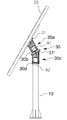
도 1은 본 발명의 바람직한 실시예에 따른 2축 구동식 태양광 발전 시스템의 구성을 도시한 사시도이다.
도 2는 도 1의 부분 투시 측면도이다.
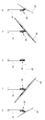
도 3은 도 1에서 태양광 패널의 수평회전 구동예를 도시한 사시도이다.
도 4는 도 1에서 회전장치에 구비되는 회전 카운트판 및 리미트 스위치의 구성을 도시한 부분 투시 사시도이다.
도 5는 도 4의 단면도이다.
도 6은 도 5의 "A"에 대한 부분 확대 단면도이다.
도 7는 도 5의 변형예를 도시한 단면도이다.1 is a perspective view showing the configuration of a two-axis driving solar power generation system according to a preferred embodiment of the present invention.
FIG. 2 is a partial perspective side view of FIG. 1 ;
3 is a perspective view illustrating an example of horizontal rotation driving of the solar panel in FIG. 1 .
Figure 4 is a partial perspective perspective view showing the configuration of the rotation counter plate and the limit switch provided in the rotary device in Figure 1.
FIG. 5 is a cross-sectional view of FIG. 4 .
6 is a partially enlarged cross-sectional view taken along line “A” of FIG. 5 .
7 is a cross-sectional view illustrating a modified example of FIG. 5 .
도 1은 본 발명의 바람직한 실시예에 따른 2축 구동식 태양광 발전 시스템의 구성을 도시한 사시도이며, 도 2는 도 1의 일부 투시 측면도이다.1 is a perspective view showing the configuration of a two-axis driven photovoltaic power generation system according to a preferred embodiment of the present invention, and FIG. 2 is a partial perspective side view of FIG. 1 .
도 1 및 도 2를 참조하면, 본 발명의 바람직한 실시예에 따른 2축 구동식 태양광 발전 시스템은, 태양광 발전 부지 등의 지면 위에 세워져서 고정되는 폴(10)과, 폴(10)의 상단에 설치된 태양광 패널(20)과, 태양광 패널(20)의 하부에 위치하고 지면에 대해 상방으로 비스듬히 경사지게 배치되어 태양광 패널(20)의 경사각을 조절하는 제1 회전부(30a)와 상기 제1 회전부(30a)의 하부에 위치하고 지면에 대해 수직하게 배치되어 태양광 패널(20)의 방위각을 조절하는 제2 회전부(30c)를 구비한 회전장치(30)를 포함한다.1 and 2, the two-axis driven photovoltaic power generation system according to a preferred embodiment of the present invention, a
폴(10)은 수직하게 세워지고 하단이 앵커볼트와 같은 체결수단에 의해 소정의 무게추 블록의 상단에 고정되어 설치된다. 바람직하게, 폴(10)은 통상의 가로등 지주와 같이 외주면이 둥근 금속 관형체로 이루어질 수 있고, 그밖에 다양한 소재와 형태로 구성될 수 있다.The
태양광 발전 부지가 산지나 임야, 휴경지 등과 같이 수목이 존재하는 곳인 경우, 태양광 발전 시스템의 시공 시 폴(10)은 주변에 수목이 위치할 수 있게 정해진 간격을 두고 서로 이격되게 복수개가 배치될 수 있다. 그밖에, 본 발명이 적용될 수 있는 태양광 발전 부지로는, 적어도 하나 이상의 소정의 무게추 블록을 매설하고 상기 무게추 블록 위에 폴(10)을 세울 수 있는 약간의 공터만 확보된다면 공장 주변이나 주택가, 공원 주변 등과 같이 다양한 장소가 채용될 수 있다.When the photovoltaic power generation site is a place where trees exist, such as a mountain, forest, or fallow land, a plurality of
태양광 패널(20)은 폴(10)의 상단에 설치되어 태양광 전기를 생산한다. 태양광 패널(20)은 회전장치(30)의 제1 회전부(30a) 일단에 비스듬히 경사진 형성된 플랜지(31)의 빗면에 고정되어 지면에 대해 경사지게 설치된다.The
회전장치(30)는 제1 회전부(30a)와, 제1 회전부(30a)의 하부에 배치된 제2 회전부(30c)를 포함한다. 제1 회전부(30a)는 일단이 태양광 패널(20)의 후면에 연결되어 태양에 대해 태양광 패널(20)의 경사각을 조절할 수 있는 회전력을 제공한다. 제2 회전부(30c)는 제1 회전부(30a)의 타단에 연결되도록 폴(10)에 설치되어 제1 회전부(30a) 및 태양광 패널(20)에 대하여 지면과 수평한 방향으로의 회전력을 제공한다. 제1 회전부(30a)와 제2 회전부(30c)는 일체로 형성되어 하나의 몸체로 구성되거나, 후술하는 바와 같이 예컨대, 플랜지 구조를 매개로 분리 가능하게 연결될 수 있다. 다른 대안으로, 제1 회전부(30a)와 제2 회전부(30c)는 별도의 플랜지 구조 없이 끝부분이 서로 연결되어 조립될 수도 있다.The
제1 회전부(30a)는 태양광 패널(20)의 후면에 일단(앞단)이 연결되어 태양광 패널(20)을 지면에 대해 비스듬히 경사진 회전축(회전중심)(A1)을 중심으로 서서히 회전시킨다. 이를 위해, 제1 회전부(30a)는 바람직하게, 회전샤프트가 지면으로부터 상방으로 비스듬히 경사지도록 배치된 구동모터(30b)를 구비한다.The
태양광 패널(20)은 회전축(A1)에 대해 경사지게 배치되고 제1 회전부(30a)에 의해 회전되어 태양에 대한 경사각이 조절될 수 있다. 바람직하게, 제1 회전부(30a)의 구동모터(30b)는 그에 구비된 회전샤프트가 회전축(A1)과 일치하도록 배치될 수 있으나, 본 발명이 이러한 구성에 한정되지 않음은 물론이다. 대안으로, 구동모터(30b)와 태양광 패널(20) 사이에는 동력전달을 위한 공지의 다양한 기어 어셈블리가 부가될 수도 있다.The
태양광 패널(20)의 설치각도는 회전축(A1)에 대하여 예컨대, 15도 내외로 비스듬히 경사지게 설치되는 것이 바람직하다. 태양광 패널(20)의 설치각도는 제1 회전부(30a) 일단에 비스듬히 경사지게 형성된 플랜지(31)의 빗면 경사 각도에 의해 결정된다.The installation angle of the
제2 회전부(30c)는 제1 회전부(30a)의 하부에 연결되어 제1 회전부(30a) 및 태양광 패널(20)을 지면에 대해 수직한 회전축(회전중심)(A2)을 중심으로 서서히 회전시켜서 태양에 대한 방위각을 조절한다. 이를 위해, 제2 회전부(30c)는 회전샤프트가 지면에 대해 수직하게 배치된 구동모터(30d)를 구비한다.The second rotating
제2 회전부(30c)의 상단에는 비스듬히 경사진 빗면을 가진 플랜지(31')가 마련되고, 플랜지(31')의 빗면 경사 각도에 의해 제2 회전부(30c)로부터 제1 회전부(30a)가 비스듬히 경사지게 배치된다. 여기서, 제1 회전부(30a)는 제2 회전부(30c)로부터 90°~ 180°의 각도 범위내에서 비스듬히 상방으로 경사지게 배치되는 것이 태양에 대한 태양광 패널(20)의 경사각 조절을 다각적으로 수행할 수 있는 점에서 바람직하다.A flange 31' having an obliquely inclined surface is provided at the upper end of the
제1 회전부(30a)와 제2 회전부(30c) 사이의 각도에 대응하여 제1 회전부(30a)의 구동모터(30b)와 제2 회전부(30c)의 구동모터(30d) 사이의 배치 각도는 적절한 범위내에서 다양하게 변형이 가능하다.The disposition angle between the driving
도 3의 (a) 내지 (e)에는 태양광 패널(20)의 방위각이 조절되는 예가 도시되어 있다. 구체적으로, 도 3의 (a)에는 제2 회전부(30c)에 의해 태양광 패널(20)이 예컨대, 동쪽을 향하게 방위각이 조절된 상태가 도시되어 있고, 도 3의 (b)에는 태양광 패널(20)이 반시계 방향으로 45도 회전하여 남동쪽을 향하게 방위각이 조절된 상태가 도시되어 있고, 도 3의 (c)에는 태양광 패널(20)이 더 회전하여 남쪽을 향하게 방위각이 조절된 상태가 도시되어 있다. 또한, 도 5의 (d)에는 태양광 패널(20)이 계속해서 반시계방향으로 45도 더 회전하여 남서쪽을 향하게 방위각이 조절된 상태가 도시되어 있고, 도 5의 (e)에는 태양광 패널(20)이 더 회전하여 서쪽을 향하게 방위각이 조절된 상태가 도시되어 있다.An example in which the azimuth angle of the
상기와 같이 제2 회전부(30c)에 의해 태양광 패널(20)의 방위각이 조절됨과 아울러 제1 회전부(30a)는 구동모터(30b)의 작동에 의해 태양광 패널(20)을 서서히 회전시켜서 태양에 대한 태양광 패널(20)의 경사각을 조절한다.As described above, the azimuth of the
태양광 패널(20)에 대한 다각적이고 정밀한 방향 제어를 위하여, 제1 회전부(30a)의 구동모터(30b) 및 제2 회전부(30c)의 구동모터(30d) 중 어느 하나는 시계방향으로 회전하고 다른 하나는 반시계방향으로 회전하는 것이 바람직하다.For multi-faceted and precise direction control of the
제1 회전부(30a)와 제2 회전부(30c)는 외형 및 구조가 서로 동일한 부재로 구성되어 서로 연쇄적으로 연결되는 것이 바람직하다. 도 4 및 도 5에는 제1 회전부(30a)와 제2 회전부(30c)의 구성이 상세히 도시되어 있다.It is preferable that the
도 4 및 도 5를 참조하면, 제1 회전부(30a)와 제2 회전부(30c)는 정해진 각도로 비스듬히 경사진 형상으로 이루어진 플랜지(31,31')와, 제2 회전부(30c)의 내부공간을 개폐하기 플랜지(31)의 중심에 착탈 가능하게 조립된 방수커버(32)와, 플랜지(31)의 하부에 연결된 제1 관형체(33)와, 제1 관형체(33)의 하부에 조립되고 하단은 폴(10)에 고정된 제2 관형체(34)와, 마이컴(미도시)에 의해 제어되어 제2 관형체(34)의 내부에 설치되어 제1 관형체(33)에 회전력을 제공하는 구동모터(30b,30d)를 포함한다.Referring to FIGS. 4 and 5 , the first
제1 관형체(33)는 플랜지(31)의 하단에 연결되고 원형의 둘레면을 가진 파이프형 구조물이다. 제1 관형체(33)와 플랜지(31,31')는 일체로 구성될 수 있고, 대안으로는 제1 관형체(33)의 상단에 플랜지(31,31')가 용접에 의해 일체화되는 것도 가능하다.The first
제2 관형체(34)는 제1 관형체(33)의 하부에 위치하도록 조립되고 원형의 둘레면을 가진 파이프형 구조물이다. 제2 관형체(34)의 하단에는 폴(10)의 상단 파이프 구조가 끼워질 수 있는 원형 슬롯이 부가될 수 있다. 중공에 폴이 끼워짐에 따라 제2 관형체(34)는 폴(10)의 상단에 고정된다.The second
제1 관형체(33)와 제2 관형체(34) 사이에는 베어링이 개재되어 있어 구조적으로 안정적이고 부드러운 회전이 이루어질 수 있다. 상기 베어링은 제1 관형체(33)와 연결되어 일체로 회전하게 되는 상부링과, 상기 상부링의 하부에 조립되고 제2 관형체(34)와 연결되는 하부링을 구비하고, 상기 상부링과 하부링 사이에는 다수의 볼이 개재될 수 있다.A bearing is interposed between the first
또한, 도 4에 나타난 바와 같이 제1 회전부(30a)와 제2 회전부(30c)는 제1 관형체(33)와 실질적으로 연결되는 회전기어(62)와, 제2 관형체(34)에 실질적으로 연결되는 고정기어(61)와, 고정기어(61)와 연결되도록 설치되어 회전기어(62)에 회전력을 제공하는 구동모터(30b,30d)와, 회전기어(62)의 하부에 배치되어 회전기어(62)와 일체로 회전하는 회전 카운트판(63)과, 고정기어(61)에 고정되어 회전기어(62)의 회전 시 회전 카운트판(63)과 접촉을 유지하는 리미트 스위치(60)를 구비한다.In addition, as shown in FIG. 4 , the
회전기어(62)는 구동모터(30b,30d)로부터 회전력을 전달받아서 고정기어(61)에 대하여 상대적으로 회전 가능하게 설치된다. 회전기어(62)와 고정기어(61)는 공지의 다양한 기어 어셈블리로 구성될 수 있다.The
구동모터(30b,30d)는 제2 관형체(34)의 내부에 바람직하게, 제2 관형체(34)와 동축을 이루도록 중심에 고정되어 회전기어(62)에 회전력을 제공한다.The driving
회전 카운트판(63)은 회전기어(62)의 하부에 고정되어 회전기어(62)와 동시에 회전하고 하부에는 원주방향으로 가면서 골(또는 홈)과 마루(또는 돌기) 구조로 이루어진 요철 패턴이 주기적으로 형성되어 있다. The
리미트 스위치(60)는 일측이 고정기어(61)에 고정되고 타측이 회전 카운트판(63)에 접촉하여 회전 카운트판(63)의 회전과 동시에 상기 요철 패턴과의 접촉을 지속적으로 유지한다. 따라서, 회전 카운트판(63)이 회전함에 따라 리미트 스위치(60)에서 온(On)/오프(Off) 신호가 반복적으로 출력된다.The
도 5 및 도 6에 도시된 바와 같이 제1 관형체(33)와 제2 관형체(34)의 접촉부에는 전원 및/또는 신호의 전달을 위한 제1 접점(36a,36b)과 제2 접점(38a,38b)이 설치된다. 제1 접점(36a,36b)과 제2 접점(38a,38b)은 각각 적어도 하나 이상의 도체링으로 구성되고 제1 관형체(33)와 제2 관형체(34)에 각각 고정되어 상하 방향으로 대향하게 배치된다. 제1 관형체(33)가 제2 관형체(34)에 대하여 회전하는 중에 상기 제1 접점(36a,36b)은 코일스프링(37)에 의해 하방으로 탄성 바이어스가 되어 제2 접점(38a,38b)과의 접촉상태를 지속적으로 유지한다. 대안으로, 제1 접점과 제2 접점 중 어느 하나는 롤 형태로 구성되고 다른 하나는 상기 롤이 구를 수 있는 도체링으로 구성되어 제1 관형체(33)의 회전 시 상기 제1 접점과 제2 접점이 상대적으로 구르면서 접촉 상태를 유지하도록 구성될 수 있다.As shown in FIGS. 5 and 6, in the contact portion of the first
다른 대안으로는, 도 7에 도시된 바와 같이 제1 관형체(33)와 제2 관형체(34) 간에는 전원 또는 신호의 전달을 위한 전선(39)이 연결될 수도 있다.Alternatively, as shown in FIG. 7 , a
상기 마이컴은 소정의 조도센서와, 계절별 회전설정시간과, 위성통신모듈에 의해 제공되는 GPS 시간정보 등에 기초하여 태양광 패널(20)의 1일 회전량을 결정하고 이를 구동모터(30b,30d)의 온/오프 제어에 적용하여 회전 제어를 수행할 수 있다. 상기 마이컴은 회전장치(30)에 내장되거나 폴(10)에 내장될 수 있고 별도의 함체에 내장되는 것도 가능하다.The microcomputer determines the daily rotation amount of the
상기 마이컴은 조도센서에서 출력되는 태양광의 조도값이 정해진 수치 이상이 되면 날이 밝아진 것으로 인식하고 제1 회전부(30a)의 구동모터(30b)와 제2 회전부(30c)의 구동모터(30d)를 작동시켜서 미리 설정된 회전단계 및/또는 시간 동안 태양광 패널(20)을 한쪽 방향으로 초 단위로 서서히 회전시킨다. 여기서, 제1 회전부(30a)의 구동모터(30b)와 제2 회전부(30c)의 구동모터(30d)는 동시에 작동할 수 있으며, 각각 미리 설정된 시간 구간에 개별적으로 작동될 수도 있다. 태양광 패널(20)이 회전하는 경로는 태양의 일조량을 고려하여 가능한 한 태양에 충분히 노출될 수 있게 설정되는 것이 바람직하다. 태양광 패널(20)을 정해진 시간동안 일정 속도로 회전시키면, 복잡한 구조의 태양광 추적장치를 별도로 사용하지 않더라도, 태양광 패널(20)을 한쪽을 향하게 정지 상태로 두는 경우에 비해 태양광 발전 전력량을 증대시킬 수 있다.When the illuminance value of sunlight output from the illuminance sensor is greater than or equal to a predetermined value, the microcomputer recognizes that the blade has become brighter and operates the driving
상기 마이컴은 회전 카운트판(63)의 회전에 따른 요철 패턴의 변화에 의해 온/오프되는 리미트 스위치(60)의 작동으로부터 태양광 패널(20)의 회전을 단계별로 구동 및 감지한다. 여기서, 태양광 패널(20)의 회전 1단계는 회전 카운트판(63)의 1주기, 즉 리미트 스위치(60)가 상기 요철 패턴에 포함된 어느 하나의 홈에 접촉한 후 다음번 홈에 접촉한 것을 카운트하여 정의될 수 있다.The microcomputer drives and senses the rotation of the
특히, 상기 마이컴은 제2 회전부(30c)의 구동모터(30d)를 제어하여 계절별로 회전 단계수를 서로 다르게 설정하여 태양광 패널(20)에 대한 1일 회전량(회전각)을 서로 다르게 제어할 수 있다. 계절별 일조량을 고려할 때, 4계절중 여름에 대해 회전 단계수를 가장 많게 설정(가장 많이 돌아가게 설정)하고 겨울에 대해 가장 적게 설정(가장 적게 돌아가게 설정)하여 회전 제어를 수행하는 것이 바람직하다. 구체적으로, 상기 마이컴은 회전 카운트판(63)의 회전 단계수를 봄/가을에는 1~11단계, 여름에는 0~12단계, 겨울에는 2~10단계로 설정하여 회전 제어를 수행한다. 이를 위해, 상기 마이컴의 메모리에는 회전단계설정치에 대한 데이터가 저장된다.In particular, the microcomputer controls the driving
부가적으로, 메인 컨트롤러는 각각의 상기 마이컴과 유,무선으로 통신하여 서로 다른 태양광 패널(20) 및 회전장치(30)를 통합적으로 관리하여 전체 태양광 패널(20)들이 실질적으로 동일한 패턴으로 회전하도록 제어한다.Additionally, the main controller communicates with each of the microcomputers by wire and wirelessly to manage the different
부가적으로, 상기 메인 컨트롤러는 우천 시 풍향을 감지하여 태양광 패널(20)을 빗방울과 마주보는 방향으로 회전시키는 제어를 수행한다. 즉, 태양광 패널(20)의 표면을 빗방울에 직접적으로 노출시킴으로써 태양광 패널(20)의 표면에 쌓인 미세먼지나 이물질 등을 효과적으로 제거할 수 있다.Additionally, the main controller senses the wind direction in case of rain and performs control to rotate the
상기와 같은 구성을 가진 본 발명은 태양광 전기의 생산 과정에서 태양광 패널(20)을 제1 회전부(30a) 및 제2 회전부(30c)를 이용해 지면에 대해 경사진 방향 및 수평 방향으로 서서히 2축 회전시킴으로써, 복잡한 구조의 태양광 추적장치를 별도로 사용하지 않더라도, 태양광 패널(20)을 한쪽을 향하게 정지 상태로 두는 경우에 비해 태양광 발전 전력량을 현저히 증대시킬 수 있다.In the present invention having the above configuration, in the production process of solar electricity, the
한편, 본 발명은 태양광 패널(20)을 지지하는 폴(10) 주변에 있는 수목을 그대로 유지할 수 있으므로 자연 훼손을 최소화하면서 친환경적인 태양광 발전 설비를 구축할 수 있다. 폴(10) 주변에 위치한 수목은 방풍림의 역할도 할 수 있으므로 태양광 패널(20)을 더욱 안정적으로 설치할 수 있다.On the other hand, the present invention can maintain the trees around the
시공 시에는 폴(10)이 설치될 지점마다 소정의 구덩이를 판 후에 무게추 블록을 매립하여 고정한 후에 무게추 블록의 상단 위에 폴(10)의 하단을 배치하고 앵커볼트로 고정시키면 간편하게 시공이 완료된다.At the time of construction, after digging a predetermined hole at each point where the
2축 구동식 태양광 발전 시스템의 운용 시에 태양광 패널(20)은 회전장치(30)에 의해 미리 설정된 시간과 속도로 회전하여 태양광 발전 전력량을 증대시킬 수 있다.When the two-axis driving type photovoltaic power generation system is operated, the
태양광 패널(20)은 회전장치(30)에 구비된 제1 회전부(30a)에 의해 회전축(A1)을 중심으로 지면에 대해 경사진 방향으로 서서히 회전하여 태양에 대한 경사각이 조절될 수 있다. 또한, 태양광 패널(20)은 회전장치(30)에 구비된 제2 회전부(30c)에 의해 회전축(A2)을 중심으로 지면에 대해 수평 방향으로 서서히 회전하여 태양에 대한 방위각이 조절될 수 있다. 이때, 제1 회전부(30a)와 제2 회전부(30c)의 어셈블리는, 동일한 외형 및 구조를 가진 제1 회전부(30a)와 제2 회전부(30c)를 서로 연쇄적으로 연결함으로써 제2 회전부(30c)로부터 제1 회전부(30a)가 정해진 각도로 비스듬히 꺾인 형상을 가진 회전장치(30)가 간편히 구성될 수 있다. 즉, 제2 회전부(30c)의 상단에 마련된 경사진 빗면을 가진 플랜지(31')에 제1 회전부(30a)의 하단이 볼트체결되어 제2 회전부(30c)의 상단에 제1 회전부(30a)가 정해진 각도로 경사지게 배치된 회전장치(30)가 구성된다. 여기서, 제1 회전부(30a)와 제2 회전부(30c)의 하단은 평평한 단면을 가진 플랜지가 마련되는 것이 바람직하다.The
회전장치(30)에 구비된 회전기어(62)의 하부에는 회전 카운트판(63)이 고정되어 회전기어(62)와 일체로 회전하고, 회전 카운트판(63)의 하부에는 리미트 스위치(60)가 지속적으로 접촉을 유지하여 회전 카운트판(63)의 요철 패턴을 감지함으로써 회전량을 단계별로 검출할 수 있다. 상기 마이컴은 회전 카운트판(63)의 회전에 따른 요철 패턴의 변화에 의해 온/오프되는 리미트 스위치(60)의 출력신호에 기초하여 회전장치(30)를 제어함으로써 태양광 패널(20)의 경사 방향 및 수평 방향 회전을 단계별로 구동하고 태양광 패널(20)이 오류없이 초단위로 회전하는지 여부도 감지하여 제어동작에 반영한다.A
상술한 바와 같이 본 발명에 따른 2축 구동식 태양광 발전 시스템은 회전장치(30)를 구성하는 제1 회전부(30a)와 제2 회전부(30c)에 의해 태양광 패널(20)의 방위각과 경사각을 모두 자유롭게 정밀 조정할 수 있으므로 태양광 발전 효율을 더욱 향상시킬 수 있는 현저한 효과가 있다. 또한, 간소한 구동장치로 태양광 패널을 회전시킴으로써 고가의 태양광 추적장치를 쓰지 않더라도 효율적으로 태양광 발전량을 증대시킬 수 있다.As described above, in the two-axis driving solar power generation system according to the present invention, the azimuth and inclination angles of the
이상에서 본 발명은 비록 한정된 실시예와 도면에 의해 설명되었으나, 본 발명은 이것에 의해 한정되지 않으며 본 발명이 속하는 기술분야에서 통상의 지식을 가진 자에 의해 본 발명의 기술사상과 아래에 기재될 특허청구범위의 균등범위 내에서 다양한 수정 및 변형이 가능함은 물론이다.In the above, although the present invention has been described with reference to limited embodiments and drawings, the present invention is not limited thereto and will be described below with the technical idea of the present invention by those of ordinary skill in the art to which the present invention pertains. Of course, various modifications and variations are possible within the scope of equivalents of the claims.
10: 폴 20: 태양광 패널
30: 회전장치 30a: 제1 회전부
30b,30d: 구동모터 30c: 제2 회전부
60: 리미트 스위치 61: 고정기어
62: 회전기어 63: 회전 카운트판10: pole 20: solar panel
30: rotating
30b, 30d: drive
60: limit switch 61: fixed gear
62: rotation gear 63: rotation counter plate
Claims (16)
지면 위에 세워지게 고정되는 폴;
상기 폴의 상단에 경사지게 설치되어 태양광 전기를 발생시키는 태양광 패널; 및
상기 폴과 상기 태양광 패널 사이에 설치되어 상기 태양광 패널에 회전력을 제공하는 회전장치;를 포함하고,
상기 회전장치는,
상기 태양광 패널의 후면에 일단이 연결되고 상기 태양광 패널을 지면에 대해 비스듬히 경사진 제1 회전축을 중심으로 회전시키는 구동모터를 구비하여 상기 태양광 패널의 경사각을 조절하는 제1 회전부와, 상기 제1 회전부의 타단에 연결되어 상기 제1 회전부의 하부에 배치되고 상기 제1 회전부를 지면에 대해 수직한 제2 회전축을 중심으로 회전시키는 구동모터를 구비하여 상기 태양광 패널의 방위각을 조절하는 제2 회전부를 포함하는 것을 특징으로 하는 2축 구동식 태양광 발전 시스템.In the two-axis driving solar power system,
poles fixed to stand on the ground;
a solar panel installed at an angle to the top of the pole to generate solar electricity; and
A rotating device installed between the pole and the solar panel to provide a rotational force to the solar panel; includes,
The rotating device is
A first rotating part having one end connected to the rear surface of the solar panel and having a driving motor for rotating the solar panel about a first rotational axis inclined at an angle with respect to the ground to adjust the inclination angle of the solar panel; The first rotating part is connected to the other end of the first rotating part and disposed under the first rotating part and comprising a driving motor for rotating the first rotating part about a second rotational axis perpendicular to the ground to adjust the azimuth of the solar panel. Two-axis driving solar power system comprising two rotating parts.
상기 제1 회전부의 구동모터 및 상기 제2 회전부의 구동모터 중 어느 하나는 시계방향으로 회전하고 다른 하나는 반시계방향으로 회전하는 것을 특징으로 하는 2축 구동식 태양광 발전 시스템.According to claim 1,
One of the driving motor of the first rotating part and the driving motor of the second rotating part rotates in a clockwise direction and the other rotates in a counterclockwise direction.
상기 제1 회전부가 상기 제2 회전부로부터 90°~ 180°의 각도로 비스듬히 경사지게 배치된 것을 특징으로 하는 2축 구동식 태양광 발전 시스템.According to claim 1,
The two-axis driving solar power generation system, characterized in that the first rotating part is disposed obliquely at an angle of 90 ° to 180 ° from the second rotating part.
상기 제1 회전부와 상기 제2 회전부는 외형 및 구조가 서로 동일한 부재인 것을 특징으로 하는 2축 구동식 태양광 발전 시스템.According to claim 1,
The two-axis driving solar power generation system, characterized in that the first rotating part and the second rotating part are members having the same external shape and structure.
상기 구동모터에 의해 회전 가능한 회전기어와, 상기 회전기어의 하부에 배치되고 원주방향으로 가면서 요철 패턴이 주기적으로 형성되어 있는 회전 카운트판과, 고정기어에 고정되어 상기 회전기어의 회전 시 상기 회전 카운트판과 접촉을 유지하는 리미트 스위치를 구비한 것을 특징으로 하는 2축 구동식 태양광 발전 시스템.5. The method of claim 4, wherein the first rotation unit and the second rotation unit,
A rotation gear rotatable by the driving motor, a rotation counter plate disposed under the rotation gear and having an uneven pattern periodically formed while going in the circumferential direction, and a rotation count plate fixed to the fixed gear and rotating the rotation gear A two-axis driven solar power system, characterized in that it has a limit switch that maintains contact with the plate.
상기 회전기어와 상기 고정기어 간의 접촉부에는 상기 회전기어의 회전 시 서로 접촉을 유지하여 전원 또는 신호를 전달하는 제1 접점과 제2 접점이 설치된 것을 특징으로 하는 2축 구동식 태양광 발전 시스템.The method of claim 5, wherein the first rotation unit and the second rotation unit,
A two-axis driving solar power generation system, characterized in that a first contact and a second contact for transmitting power or a signal by maintaining contact with each other when the rotary gear is rotated are installed in the contact portion between the rotary gear and the fixed gear.
상기 회전기어와 상기 고정기어를 수용하는 관형체들 간에 전원 또는 신호의 전달을 위한 전선이 연결된 것을 특징으로 하는 2축 구동식 태양광 발전 시스템.The method of claim 5, wherein the first rotation unit and the second rotation unit,
A two-axis driving solar power generation system, characterized in that a wire for transmitting power or a signal is connected between the rotary gear and the tubular bodies accommodating the fixed gear.
상기 회전 카운트판의 요철 패턴에 따라 온/오프되는 상기 리미트 스위치의 작동으로부터 상기 태양광 패널의 회전을 단계별로 구동제어 및 감지하는 마이컴;을 구비하고,
상기 마이컴은 상기 제2 회전부를 구동하여 상기 태양광 패널을 한쪽 방향으로만 회전시키는 것을 특징으로 하는 2축 구동식 태양광 발전 시스템.6. The method of claim 5,
and a microcomputer for step-by-step driving control and sensing of the rotation of the solar panel from the operation of the limit switch turned on/off according to the concave-convex pattern of the rotation counter plate,
The microcomputer drives the second rotating part to rotate the solar panel in only one direction.
우천 시 풍향을 감지하여 상기 태양광 패널을 빗방울과 마주보는 방향으로 회전시켜 상기 태양광 패널을 청소하는 제어를 수행하는 메인 콘트롤러;를 더 포함하는 2축 구동식 태양광 발전 시스템.6. The method of claim 5,
The two-axis driven solar power system further comprising a; by sensing the wind direction in case of rain and rotating the solar panel in a direction facing the raindrops to control the cleaning of the solar panel.
상기 제1 회전부와 상기 제2 회전부는 일체로 형성되거나 분리 가능하게 연결된 것을 특징으로 하는 2축 구동식 태양광 발전 시스템.According to claim 1,
The two-axis driving solar power generation system, characterized in that the first rotating part and the second rotating part are integrally formed or are detachably connected.
태양광 패널의 후면에 일단이 연결되고 상기 태양광 패널을 지면에 대해 비스듬히 경사진 제1 회전축을 중심으로 회전시키는 구동모터를 구비하여 상기 태양광 패널의 경사각을 조절하는 제1 회전부; 및
상기 제1 회전부의 타단에 연결되어 상기 제1 회전부의 하부에 배치되고 상기 제1 회전부를 지면에 대해 수직한 제2 회전축을 중심으로 회전시키는 구동모터를 구비하여 상기 태양광 패널의 방위각을 조절하는 제2 회전부;를 포함하는 것을 특징으로 하는 2축 구동식 태양광 발전 시스템의 회전장치.In the rotating device of the two-axis driving solar power generation system,
a first rotation unit having one end connected to the rear surface of the solar panel and having a driving motor for rotating the solar panel about a first rotational axis inclined at an angle with respect to the ground to adjust the inclination angle of the solar panel; and
It is connected to the other end of the first rotating part and is disposed under the first rotating part and includes a driving motor for rotating the first rotating part about a second rotational axis perpendicular to the ground to adjust the azimuth of the solar panel. A second rotating unit; a rotating device of a two-axis driving solar power generation system comprising a.
상기 제1 회전부의 구동모터 및 상기 제2 회전부의 구동모터 중 어느 하나는 시계방향으로 회전하고 다른 하나는 반시계방향으로 회전하는 것을 특징으로 하는 2축 구동식 태양광 발전 시스템의 회전장치.12. The method of claim 11,
One of the driving motor of the first rotating unit and the driving motor of the second rotating unit rotates in a clockwise direction and the other rotates in a counterclockwise direction.
상기 제1 회전부가 상기 제2 회전부로부터 90°~ 180°의 각도로 비스듬히 경사지게 배치된 것을 특징으로 하는 2축 구동식 태양광 발전 시스템의 회전장치.12. The method of claim 11,
The rotating device of the two-axis driving solar power generation system, characterized in that the first rotating part is disposed obliquely at an angle of 90 ° to 180 ° from the second rotating part.
상기 제1 회전부와 상기 제2 회전부는 외형 및 구조가 서로 동일한 부재인 것을 특징으로 하는 2축 구동식 태양광 발전 시스템의 회전장치.12. The method of claim 11,
The first rotating unit and the second rotating unit of the two-axis driving solar power generation system, characterized in that the member having the same external shape and structure as each other.
상기 구동모터에 의해 회전 가능한 회전기어와, 상기 회전기어의 하부에 배치되고 원주방향으로 가면서 요철 패턴이 주기적으로 형성되어 있는 회전 카운트판과, 고정기어에 고정되어 상기 회전기어의 회전 시 상기 회전 카운트판과 접촉을 유지하는 리미트 스위치를 구비한 것을 특징으로 하는 2축 구동식 태양광 발전 시스템의 회전장치.12. The method of claim 11, wherein the first rotation unit and the second rotation unit,
A rotation gear rotatable by the driving motor, a rotation counter plate disposed under the rotation gear and having an uneven pattern periodically formed while going in the circumferential direction, and a rotation count plate fixed to the fixed gear and rotating the rotation gear A rotating device for a two-axis driven photovoltaic system, characterized in that it has a limit switch that maintains contact with the plate.
상기 제1 회전부와 상기 제2 회전부는 일체로 형성되거나 분리 가능하게 연결된 것을 특징으로 하는 2축 구동식 태양광 발전 시스템의 회전장치.
12. The method of claim 11,
The first rotating part and the second rotating part are integrally formed or a rotating device of a two-axis driving solar power generation system, characterized in that it is detachably connected.
Priority Applications (2)
| Application Number | Priority Date | Filing Date | Title |
|---|---|---|---|
| KR1020190160146A KR20210070094A (en) | 2019-12-04 | 2019-12-04 | Solar energy generation system having two-axis driving structure |
| PCT/KR2019/017272 WO2020141743A1 (en) | 2018-12-31 | 2019-12-09 | Dual axis-driven solar energy generation system |
Applications Claiming Priority (1)
| Application Number | Priority Date | Filing Date | Title |
|---|---|---|---|
| KR1020190160146A KR20210070094A (en) | 2019-12-04 | 2019-12-04 | Solar energy generation system having two-axis driving structure |
Publications (1)
| Publication Number | Publication Date |
|---|---|
| KR20210070094A true KR20210070094A (en) | 2021-06-14 |
Family
ID=76417570
Family Applications (1)
| Application Number | Title | Priority Date | Filing Date |
|---|---|---|---|
| KR1020190160146A KR20210070094A (en) | 2018-12-31 | 2019-12-04 | Solar energy generation system having two-axis driving structure |
Country Status (1)
| Country | Link |
|---|---|
| KR (1) | KR20210070094A (en) |
Cited By (5)
| Publication number | Priority date | Publication date | Assignee | Title |
|---|---|---|---|---|
| KR102423249B1 (en) * | 2021-11-19 | 2022-07-22 | 주식회사 원광에스앤티 | Movable type photovoltaic power generation device for farming |
| KR102472654B1 (en) * | 2022-02-17 | 2022-11-30 | 이상헌 | Movable type photovoltaic power generation device for farming |
| KR102534460B1 (en) * | 2022-02-17 | 2023-05-26 | 이상헌 | Movable type photovoltaic power generation device for farming |
| KR102539333B1 (en) * | 2022-02-17 | 2023-06-02 | 이상헌 | Movable type photovoltaic power generation device for farming with freezing protective structure |
| CN116707393A (en) * | 2023-08-04 | 2023-09-05 | 远山建安技术有限公司 | Breeze-light serial complementary power station |
Citations (2)
| Publication number | Priority date | Publication date | Assignee | Title |
|---|---|---|---|---|
| KR20110024887A (en) | 2009-09-03 | 2011-03-09 | 주식회사 디엠에스 | Photo voltaic power generation system |
| KR20160086729A (en) | 2015-01-12 | 2016-07-20 | 김한식 | The sunbeam module and method in which I installed in the rice paddy |
-
2019
- 2019-12-04 KR KR1020190160146A patent/KR20210070094A/en not_active Application Discontinuation
Patent Citations (2)
| Publication number | Priority date | Publication date | Assignee | Title |
|---|---|---|---|---|
| KR20110024887A (en) | 2009-09-03 | 2011-03-09 | 주식회사 디엠에스 | Photo voltaic power generation system |
| KR20160086729A (en) | 2015-01-12 | 2016-07-20 | 김한식 | The sunbeam module and method in which I installed in the rice paddy |
Cited By (8)
| Publication number | Priority date | Publication date | Assignee | Title |
|---|---|---|---|---|
| KR102423249B1 (en) * | 2021-11-19 | 2022-07-22 | 주식회사 원광에스앤티 | Movable type photovoltaic power generation device for farming |
| WO2023090505A1 (en) * | 2021-11-19 | 2023-05-25 | 주식회사 원광에스앤티 | Movable agrivoltaic device |
| KR20230074397A (en) * | 2021-11-19 | 2023-05-30 | 주식회사 원광에스앤티 | Movable type photovoltaic power generation device for farming |
| KR102472654B1 (en) * | 2022-02-17 | 2022-11-30 | 이상헌 | Movable type photovoltaic power generation device for farming |
| KR102534460B1 (en) * | 2022-02-17 | 2023-05-26 | 이상헌 | Movable type photovoltaic power generation device for farming |
| KR102539333B1 (en) * | 2022-02-17 | 2023-06-02 | 이상헌 | Movable type photovoltaic power generation device for farming with freezing protective structure |
| CN116707393A (en) * | 2023-08-04 | 2023-09-05 | 远山建安技术有限公司 | Breeze-light serial complementary power station |
| CN116707393B (en) * | 2023-08-04 | 2023-10-20 | 远山建安技术有限公司 | Breeze-light serial complementary power station |
Similar Documents
| Publication | Publication Date | Title |
|---|---|---|
| KR20210070094A (en) | Solar energy generation system having two-axis driving structure | |
| KR20210070085A (en) | Pole type solar energy generation system | |
| JP7202583B2 (en) | smart solar power system | |
| KR100819861B1 (en) | Solar tracker | |
| JP3212175U (en) | Grid assembly type intelligent photovoltaic system | |
| KR100968402B1 (en) | Apparatus for tracking condensing sunlight of sliding type | |
| US7705277B2 (en) | Sun tracking solar panels | |
| KR102001242B1 (en) | Solar photovoltaic device installed in agriculture and livestock area | |
| US20210194417A1 (en) | Elevated dual-axis photovoltaic solar tracking assembly | |
| KR102265876B1 (en) | A multipurpose of smart solar power device | |
| KR20110124043A (en) | A revolving house equipped with solar tracking apparatus | |
| CN106130459A (en) | A kind of photovoltaic bracket realizing automatic tracing sunlight optimized incidence | |
| KR101040803B1 (en) | Apparatus for sliding tracking condensing sunlight on road type | |
| KR20130137433A (en) | Solar generating apparatus | |
| KR20210070102A (en) | One-axis driving type solar energy generation system having gradient structure | |
| KR100687140B1 (en) | The sun rays tracking for the energy production of electric power system | |
| JP2002134777A (en) | Solar cell panel light collector | |
| CN112394749B (en) | Solar photovoltaic operation and maintenance control system based on tracking control and field data acquisition | |
| KR20130093453A (en) | Solar generating apparatus | |
| KR102079713B1 (en) | A hybrid apparatus for generating wind power and sola power established to arable land | |
| KR102176010B1 (en) | Environment friendly solar energy generation system | |
| KR100882192B1 (en) | The sun rays tracking for the energy production ofelectric power system | |
| KR102271287B1 (en) | Smart solar energy generation system | |
| KR101164796B1 (en) | Pole type solar tracker | |
| KR200405781Y1 (en) | The sun rays tracking for the energy production of electric power system |
Legal Events
| Date | Code | Title | Description |
|---|---|---|---|
| E601 | Decision to refuse application |