JP7202583B2 - smart solar power system - Google Patents
smart solar power system Download PDFInfo
- Publication number
- JP7202583B2 JP7202583B2 JP2021533289A JP2021533289A JP7202583B2 JP 7202583 B2 JP7202583 B2 JP 7202583B2 JP 2021533289 A JP2021533289 A JP 2021533289A JP 2021533289 A JP2021533289 A JP 2021533289A JP 7202583 B2 JP7202583 B2 JP 7202583B2
- Authority
- JP
- Japan
- Prior art keywords
- solar panel
- rotation
- tubular body
- solar
- pole
- Prior art date
- Legal status (The legal status is an assumption and is not a legal conclusion. Google has not performed a legal analysis and makes no representation as to the accuracy of the status listed.)
- Active
Links
- 238000010248 power generation Methods 0.000 claims description 67
- 230000005611 electricity Effects 0.000 claims description 20
- 230000003028 elevating effect Effects 0.000 description 56
- 238000001514 detection method Methods 0.000 description 25
- 238000013459 approach Methods 0.000 description 14
- 238000004891 communication Methods 0.000 description 13
- 238000012423 maintenance Methods 0.000 description 9
- 238000004140 cleaning Methods 0.000 description 8
- 238000009434 installation Methods 0.000 description 8
- 238000010276 construction Methods 0.000 description 6
- 230000001965 increasing effect Effects 0.000 description 6
- 230000006378 damage Effects 0.000 description 5
- 230000000694 effects Effects 0.000 description 4
- 230000006870 function Effects 0.000 description 4
- 239000000463 material Substances 0.000 description 4
- 238000004804 winding Methods 0.000 description 4
- 238000010586 diagram Methods 0.000 description 3
- 230000007613 environmental effect Effects 0.000 description 3
- 238000005286 illumination Methods 0.000 description 3
- 238000003466 welding Methods 0.000 description 3
- 239000004020 conductor Substances 0.000 description 2
- 239000000428 dust Substances 0.000 description 2
- 239000002184 metal Substances 0.000 description 2
- 238000000034 method Methods 0.000 description 2
- 238000012986 modification Methods 0.000 description 2
- 230000004048 modification Effects 0.000 description 2
- 230000002265 prevention Effects 0.000 description 2
- 239000004576 sand Substances 0.000 description 2
- 230000001932 seasonal effect Effects 0.000 description 2
- XLYOFNOQVPJJNP-UHFFFAOYSA-N water Substances O XLYOFNOQVPJJNP-UHFFFAOYSA-N 0.000 description 2
- 241000112598 Pseudoblennius percoides Species 0.000 description 1
- 238000009825 accumulation Methods 0.000 description 1
- 230000000712 assembly Effects 0.000 description 1
- 238000000429 assembly Methods 0.000 description 1
- 230000005540 biological transmission Effects 0.000 description 1
- 230000015556 catabolic process Effects 0.000 description 1
- 238000005520 cutting process Methods 0.000 description 1
- 238000005516 engineering process Methods 0.000 description 1
- 239000011521 glass Substances 0.000 description 1
- 230000005484 gravity Effects 0.000 description 1
- 238000003306 harvesting Methods 0.000 description 1
- 239000004973 liquid crystal related substance Substances 0.000 description 1
- 230000002093 peripheral effect Effects 0.000 description 1
- 230000003014 reinforcing effect Effects 0.000 description 1
- 238000005096 rolling process Methods 0.000 description 1
- 150000003839 salts Chemical class 0.000 description 1
- 239000002689 soil Substances 0.000 description 1
- 239000000725 suspension Substances 0.000 description 1
Images


Classifications
-
- F—MECHANICAL ENGINEERING; LIGHTING; HEATING; WEAPONS; BLASTING
- F21—LIGHTING
- F21S—NON-PORTABLE LIGHTING DEVICES; SYSTEMS THEREOF; VEHICLE LIGHTING DEVICES SPECIALLY ADAPTED FOR VEHICLE EXTERIORS
- F21S9/00—Lighting devices with a built-in power supply; Systems employing lighting devices with a built-in power supply
- F21S9/02—Lighting devices with a built-in power supply; Systems employing lighting devices with a built-in power supply the power supply being a battery or accumulator
- F21S9/03—Lighting devices with a built-in power supply; Systems employing lighting devices with a built-in power supply the power supply being a battery or accumulator rechargeable by exposure to light
- F21S9/032—Lighting devices with a built-in power supply; Systems employing lighting devices with a built-in power supply the power supply being a battery or accumulator rechargeable by exposure to light the solar unit being separate from the lighting unit
-
- F—MECHANICAL ENGINEERING; LIGHTING; HEATING; WEAPONS; BLASTING
- F21—LIGHTING
- F21S—NON-PORTABLE LIGHTING DEVICES; SYSTEMS THEREOF; VEHICLE LIGHTING DEVICES SPECIALLY ADAPTED FOR VEHICLE EXTERIORS
- F21S8/00—Lighting devices intended for fixed installation
- F21S8/08—Lighting devices intended for fixed installation with a standard
- F21S8/085—Lighting devices intended for fixed installation with a standard of high-built type, e.g. street light
-
- F—MECHANICAL ENGINEERING; LIGHTING; HEATING; WEAPONS; BLASTING
- F21—LIGHTING
- F21V—FUNCTIONAL FEATURES OR DETAILS OF LIGHTING DEVICES OR SYSTEMS THEREOF; STRUCTURAL COMBINATIONS OF LIGHTING DEVICES WITH OTHER ARTICLES, NOT OTHERWISE PROVIDED FOR
- F21V21/00—Supporting, suspending, or attaching arrangements for lighting devices; Hand grips
- F21V21/36—Hoisting or lowering devices, e.g. for maintenance
- F21V21/38—Hoisting or lowering devices, e.g. for maintenance with a cable
-
- F—MECHANICAL ENGINEERING; LIGHTING; HEATING; WEAPONS; BLASTING
- F21—LIGHTING
- F21V—FUNCTIONAL FEATURES OR DETAILS OF LIGHTING DEVICES OR SYSTEMS THEREOF; STRUCTURAL COMBINATIONS OF LIGHTING DEVICES WITH OTHER ARTICLES, NOT OTHERWISE PROVIDED FOR
- F21V23/00—Arrangement of electric circuit elements in or on lighting devices
- F21V23/04—Arrangement of electric circuit elements in or on lighting devices the elements being switches
- F21V23/0435—Arrangement of electric circuit elements in or on lighting devices the elements being switches activated by remote control means
-
- F—MECHANICAL ENGINEERING; LIGHTING; HEATING; WEAPONS; BLASTING
- F21—LIGHTING
- F21V—FUNCTIONAL FEATURES OR DETAILS OF LIGHTING DEVICES OR SYSTEMS THEREOF; STRUCTURAL COMBINATIONS OF LIGHTING DEVICES WITH OTHER ARTICLES, NOT OTHERWISE PROVIDED FOR
- F21V23/00—Arrangement of electric circuit elements in or on lighting devices
- F21V23/04—Arrangement of electric circuit elements in or on lighting devices the elements being switches
- F21V23/0442—Arrangement of electric circuit elements in or on lighting devices the elements being switches activated by means of a sensor, e.g. motion or photodetectors
- F21V23/0471—Arrangement of electric circuit elements in or on lighting devices the elements being switches activated by means of a sensor, e.g. motion or photodetectors the sensor detecting the proximity, the presence or the movement of an object or a person
-
- G—PHYSICS
- G08—SIGNALLING
- G08B—SIGNALLING OR CALLING SYSTEMS; ORDER TELEGRAPHS; ALARM SYSTEMS
- G08B13/00—Burglar, theft or intruder alarms
- G08B13/18—Actuation by interference with heat, light, or radiation of shorter wavelength; Actuation by intruding sources of heat, light, or radiation of shorter wavelength
- G08B13/189—Actuation by interference with heat, light, or radiation of shorter wavelength; Actuation by intruding sources of heat, light, or radiation of shorter wavelength using passive radiation detection systems
- G08B13/194—Actuation by interference with heat, light, or radiation of shorter wavelength; Actuation by intruding sources of heat, light, or radiation of shorter wavelength using passive radiation detection systems using image scanning and comparing systems
- G08B13/196—Actuation by interference with heat, light, or radiation of shorter wavelength; Actuation by intruding sources of heat, light, or radiation of shorter wavelength using passive radiation detection systems using image scanning and comparing systems using television cameras
- G08B13/19617—Surveillance camera constructional details
- G08B13/19632—Camera support structures, e.g. attachment means, poles
-
- G—PHYSICS
- G08—SIGNALLING
- G08B—SIGNALLING OR CALLING SYSTEMS; ORDER TELEGRAPHS; ALARM SYSTEMS
- G08B13/00—Burglar, theft or intruder alarms
- G08B13/18—Actuation by interference with heat, light, or radiation of shorter wavelength; Actuation by intruding sources of heat, light, or radiation of shorter wavelength
- G08B13/189—Actuation by interference with heat, light, or radiation of shorter wavelength; Actuation by intruding sources of heat, light, or radiation of shorter wavelength using passive radiation detection systems
- G08B13/194—Actuation by interference with heat, light, or radiation of shorter wavelength; Actuation by intruding sources of heat, light, or radiation of shorter wavelength using passive radiation detection systems using image scanning and comparing systems
- G08B13/196—Actuation by interference with heat, light, or radiation of shorter wavelength; Actuation by intruding sources of heat, light, or radiation of shorter wavelength using passive radiation detection systems using image scanning and comparing systems using television cameras
- G08B13/19639—Details of the system layout
- G08B13/19641—Multiple cameras having overlapping views on a single scene
-
- G—PHYSICS
- G08—SIGNALLING
- G08B—SIGNALLING OR CALLING SYSTEMS; ORDER TELEGRAPHS; ALARM SYSTEMS
- G08B13/00—Burglar, theft or intruder alarms
- G08B13/18—Actuation by interference with heat, light, or radiation of shorter wavelength; Actuation by intruding sources of heat, light, or radiation of shorter wavelength
- G08B13/189—Actuation by interference with heat, light, or radiation of shorter wavelength; Actuation by intruding sources of heat, light, or radiation of shorter wavelength using passive radiation detection systems
- G08B13/194—Actuation by interference with heat, light, or radiation of shorter wavelength; Actuation by intruding sources of heat, light, or radiation of shorter wavelength using passive radiation detection systems using image scanning and comparing systems
- G08B13/196—Actuation by interference with heat, light, or radiation of shorter wavelength; Actuation by intruding sources of heat, light, or radiation of shorter wavelength using passive radiation detection systems using image scanning and comparing systems using television cameras
- G08B13/19695—Arrangements wherein non-video detectors start video recording or forwarding but do not generate an alarm themselves
-
- G—PHYSICS
- G08—SIGNALLING
- G08B—SIGNALLING OR CALLING SYSTEMS; ORDER TELEGRAPHS; ALARM SYSTEMS
- G08B29/00—Checking or monitoring of signalling or alarm systems; Prevention or correction of operating errors, e.g. preventing unauthorised operation
- G08B29/18—Prevention or correction of operating errors
- G08B29/181—Prevention or correction of operating errors due to failing power supply
-
- H—ELECTRICITY
- H02—GENERATION; CONVERSION OR DISTRIBUTION OF ELECTRIC POWER
- H02S—GENERATION OF ELECTRIC POWER BY CONVERSION OF INFRARED RADIATION, VISIBLE LIGHT OR ULTRAVIOLET LIGHT, e.g. USING PHOTOVOLTAIC [PV] MODULES
- H02S20/00—Supporting structures for PV modules
- H02S20/30—Supporting structures being movable or adjustable, e.g. for angle adjustment
- H02S20/32—Supporting structures being movable or adjustable, e.g. for angle adjustment specially adapted for solar tracking
-
- H—ELECTRICITY
- H04—ELECTRIC COMMUNICATION TECHNIQUE
- H04N—PICTORIAL COMMUNICATION, e.g. TELEVISION
- H04N23/00—Cameras or camera modules comprising electronic image sensors; Control thereof
- H04N23/57—Mechanical or electrical details of cameras or camera modules specially adapted for being embedded in other devices
-
- H—ELECTRICITY
- H04—ELECTRIC COMMUNICATION TECHNIQUE
- H04N—PICTORIAL COMMUNICATION, e.g. TELEVISION
- H04N7/00—Television systems
- H04N7/18—Closed-circuit television [CCTV] systems, i.e. systems in which the video signal is not broadcast
-
- F—MECHANICAL ENGINEERING; LIGHTING; HEATING; WEAPONS; BLASTING
- F21—LIGHTING
- F21V—FUNCTIONAL FEATURES OR DETAILS OF LIGHTING DEVICES OR SYSTEMS THEREOF; STRUCTURAL COMBINATIONS OF LIGHTING DEVICES WITH OTHER ARTICLES, NOT OTHERWISE PROVIDED FOR
- F21V33/00—Structural combinations of lighting devices with other articles, not otherwise provided for
- F21V33/0064—Health, life-saving or fire-fighting equipment
- F21V33/0076—Safety or security signalisation, e.g. smoke or burglar alarms, earthquake detectors; Self-defence devices
-
- F—MECHANICAL ENGINEERING; LIGHTING; HEATING; WEAPONS; BLASTING
- F21—LIGHTING
- F21W—INDEXING SCHEME ASSOCIATED WITH SUBCLASSES F21K, F21L, F21S and F21V, RELATING TO USES OR APPLICATIONS OF LIGHTING DEVICES OR SYSTEMS
- F21W2131/00—Use or application of lighting devices or systems not provided for in codes F21W2102/00-F21W2121/00
- F21W2131/10—Outdoor lighting
- F21W2131/103—Outdoor lighting of streets or roads
-
- Y—GENERAL TAGGING OF NEW TECHNOLOGICAL DEVELOPMENTS; GENERAL TAGGING OF CROSS-SECTIONAL TECHNOLOGIES SPANNING OVER SEVERAL SECTIONS OF THE IPC; TECHNICAL SUBJECTS COVERED BY FORMER USPC CROSS-REFERENCE ART COLLECTIONS [XRACs] AND DIGESTS
- Y02—TECHNOLOGIES OR APPLICATIONS FOR MITIGATION OR ADAPTATION AGAINST CLIMATE CHANGE
- Y02B—CLIMATE CHANGE MITIGATION TECHNOLOGIES RELATED TO BUILDINGS, e.g. HOUSING, HOUSE APPLIANCES OR RELATED END-USER APPLICATIONS
- Y02B10/00—Integration of renewable energy sources in buildings
- Y02B10/10—Photovoltaic [PV]
-
- Y—GENERAL TAGGING OF NEW TECHNOLOGICAL DEVELOPMENTS; GENERAL TAGGING OF CROSS-SECTIONAL TECHNOLOGIES SPANNING OVER SEVERAL SECTIONS OF THE IPC; TECHNICAL SUBJECTS COVERED BY FORMER USPC CROSS-REFERENCE ART COLLECTIONS [XRACs] AND DIGESTS
- Y02—TECHNOLOGIES OR APPLICATIONS FOR MITIGATION OR ADAPTATION AGAINST CLIMATE CHANGE
- Y02B—CLIMATE CHANGE MITIGATION TECHNOLOGIES RELATED TO BUILDINGS, e.g. HOUSING, HOUSE APPLIANCES OR RELATED END-USER APPLICATIONS
- Y02B20/00—Energy efficient lighting technologies, e.g. halogen lamps or gas discharge lamps
- Y02B20/40—Control techniques providing energy savings, e.g. smart controller or presence detection
-
- Y—GENERAL TAGGING OF NEW TECHNOLOGICAL DEVELOPMENTS; GENERAL TAGGING OF CROSS-SECTIONAL TECHNOLOGIES SPANNING OVER SEVERAL SECTIONS OF THE IPC; TECHNICAL SUBJECTS COVERED BY FORMER USPC CROSS-REFERENCE ART COLLECTIONS [XRACs] AND DIGESTS
- Y02—TECHNOLOGIES OR APPLICATIONS FOR MITIGATION OR ADAPTATION AGAINST CLIMATE CHANGE
- Y02B—CLIMATE CHANGE MITIGATION TECHNOLOGIES RELATED TO BUILDINGS, e.g. HOUSING, HOUSE APPLIANCES OR RELATED END-USER APPLICATIONS
- Y02B20/00—Energy efficient lighting technologies, e.g. halogen lamps or gas discharge lamps
- Y02B20/72—Energy efficient lighting technologies, e.g. halogen lamps or gas discharge lamps in street lighting
-
- Y—GENERAL TAGGING OF NEW TECHNOLOGICAL DEVELOPMENTS; GENERAL TAGGING OF CROSS-SECTIONAL TECHNOLOGIES SPANNING OVER SEVERAL SECTIONS OF THE IPC; TECHNICAL SUBJECTS COVERED BY FORMER USPC CROSS-REFERENCE ART COLLECTIONS [XRACs] AND DIGESTS
- Y02—TECHNOLOGIES OR APPLICATIONS FOR MITIGATION OR ADAPTATION AGAINST CLIMATE CHANGE
- Y02E—REDUCTION OF GREENHOUSE GAS [GHG] EMISSIONS, RELATED TO ENERGY GENERATION, TRANSMISSION OR DISTRIBUTION
- Y02E10/00—Energy generation through renewable energy sources
- Y02E10/50—Photovoltaic [PV] energy
Description
本出願は,2018年12月31日出願の韓国特許出願第10-2018-0173998号に基づく優先権を主張し,当該出願の明細書及び図面に開示された全内容を採用するものである。 This application claims priority from Korean Patent Application No. 10-2018-0173998 filed on December 31, 2018, and adopts all contents disclosed in the specification and drawings of the application.
本発明は、太陽発電システムに係り、さらに詳しくは、環境破壊を最小限に抑えつつ、発電効率の高い太陽光発電設備を構築することが可能な構造を有するスマート太陽光発電システムに関する。 TECHNICAL FIELD The present invention relates to a solar power generation system, and more particularly to a smart solar power generation system having a structure capable of constructing a solar power generation facility with high power generation efficiency while minimizing environmental destruction.
一般に、太陽光発電システムは、林野や休耕地、建物屋根、貯水池、塩田等の敷地に多数の太陽光パネルを集合させて団地化したものである。 In general, a photovoltaic power generation system is formed by collecting a large number of photovoltaic panels on sites such as forests, fallow lands, building roofs, reservoirs, and salt fields.
太陽光発電の敷地が林野や農地等の場合、伐採や土木工事を行い、敷地の整備作業を終えた後に、フレーム構造と太陽光パネルを設置する必要があるので、必然的に樹木と土砂が大規模に毀損される環境破壊の問題が生じる。このような副作用により、太陽光発電に必要な場所の条件を満たしながらも、林野等を太陽光発電の敷地として利用するのは、実際には容易ではない。 If the site for photovoltaic power generation is a forest or agricultural land, it is necessary to install the frame structure and solar panels after performing felling and civil engineering work and completing the site maintenance work, so trees and soil will inevitably occur. The problem of environmental destruction, which is extensively damaged, arises. Due to such side effects, it is actually not easy to use a forest or the like as a site for photovoltaic power generation while satisfying the site conditions necessary for photovoltaic power generation.
韓国公開特許公報第2011-0024887号は、建物の屋上や堤防等のなどに非破壊的に設置できる自重式太陽光発電装置を開示している。前記自重式太陽光発電装は、少なくとも一つ以上の柱を連続的に連結することにより形成された柱部アセンブリと、柱部アセンブリの上部に結合される集光板とを備え、前記柱は、上面に傾斜面を有し、内部に充填材を収容する充填材収容空間を有する。 Korean Patent Publication No. 2011-0024887 discloses a self-weighted photovoltaic power generation device that can be installed nondestructively on the roof of a building, embankment, or the like. The gravity type photovoltaic power generation device includes a column assembly formed by continuously connecting at least one or more columns, and a light collecting plate coupled to an upper portion of the column assembly, the column comprising: It has an inclined surface on the upper surface and a filling material accommodating space for containing the filling material inside.
韓国公開特許公報第2016-0086729号は、畑や水田を占有しない太陽光モジュールの設置方法に関するものであり、収穫後の非農業時期に畑や水田に光起電モジュールを容易に設置できるように、下部支持体、設置固定枠、及び支柱枠を備える、水田に設置可能な太陽光モジュール及び方法を開示している。また、韓国公開特許公報第2016-0086729号は、簡便施工太陽光モジュールの設置固定枠を、他の簡便施工太陽光モジュールの保護枠の一側にヒンジ手段により連結することにより、複数の簡便施工太陽光モジュールを重ね備え、使用時には広げて施工できる構造を有する太陽光モジュールを開示している。 Korean Patent Publication No. 2016-0086729 relates to a method for installing a solar module that does not occupy fields or paddy fields, so that photovoltaic modules can be easily installed in fields or paddy fields during the non-agricultural season after harvest. , a bottom support, a mounting fixing frame, and a strut frame, a solar module and method that can be installed in a paddy field. In addition, Korean Patent Publication No. 2016-0086729 discloses that an installation fixing frame of an easy-to-install solar module is connected to one side of a protection frame of another easy-to-install solar module by means of a hinge, whereby a plurality of easy-to-install solar modules are installed. A solar module is disclosed that has a structure in which solar modules are superimposed and that can be spread out and constructed when used.
しかし、従来の太陽光発電システムは、太陽光パネルを支えるフレーム構造物の占有面積が大きいので、施工時に自然を著しく害する問題を抱えており、代替案が必要である。 However, the conventional photovoltaic power generation system has a problem that the frame structure supporting the photovoltaic panel occupies a large area, so that there is a problem of remarkably harming nature during construction, and an alternative solution is necessary.
また、従来の太陽光発電システムは、通常、太陽光パネルを固定的に設置するため、太陽光発電の効率が低いという欠点がある。太陽光発電のために太陽の移動を追跡して太陽光パネルを移動させるシステムが開示されているが、装置が複雑で高価であることから、システムの構築が容易ではないという問題がある。 In addition, conventional photovoltaic power generation systems usually have a fixed installation of photovoltaic panels, and thus have the disadvantage of low photovoltaic power generation efficiency. A system for tracking the movement of the sun and moving the solar panel for photovoltaic power generation has been disclosed.
なお、CCTVカメラや照明灯を、太陽光発電システムに追加して組み合わせてもよい。しかし、CCTVカメラや照明灯は高所に設置される特性上、長期間使用する場合には、埃の蓄積や風等の外部環境の変化によって機能が低下するという問題がある。また、CCTVカメラや照明灯の修理や清掃を行う際には、高所用のはしご車や荷役クレーンなどの高価な設備をレンタルして使用する必要があるため、メンテナンスコストが高く、車道を占有するので通行を妨げる可能性がある。 Note that a CCTV camera and illumination lamps may be added and combined with the photovoltaic power generation system. However, since CCTV cameras and lighting lamps are installed at high places, there is a problem that when they are used for a long period of time, their functions deteriorate due to the accumulation of dust and changes in the external environment such as wind. In addition, when repairing or cleaning CCTV cameras and lighting, it is necessary to rent and use expensive equipment such as ladder trucks and cargo cranes for high places, so maintenance costs are high and roads are occupied. It may impede traffic.
夜間に歩行者等がCCTVカメラの監視エリアに近づくと、CCTVカメラ及び照明設備は、CCTVカメラに装着された検知センサにより歩行者が検知され、照明灯が自動的に点灯するとともに、CCTVカメラが作動して被写体を撮影する動作を行う。 When pedestrians, etc. approach the area monitored by CCTV cameras at night, the pedestrians are detected by the detection sensors attached to the CCTV cameras and lighting equipment, and the lighting automatically turns on and the CCTV cameras are activated. It operates to photograph the subject.
しかし、歩行者が検知センサの検知範囲を越えて電柱(ポール)の反対側に移動すると、電柱自体に覆われて歩行者の接近が検知センサに検知されないため、照明灯やカメラの作動に問題が発生する。したがって、これに対する対策が必要となる。 However, if a pedestrian exceeds the detection range of the detection sensor and moves to the opposite side of the utility pole, the utility pole itself will cover the pedestrian and the approach of the pedestrian will not be detected by the detection sensor, causing problems in the operation of lighting and cameras. occurs. Therefore, countermeasures against this are required.
本発明は、上記問題に鑑みて案出されたものであり、その目的は、簡素な駆動装置を用いて太陽光パネルを所定の速度で回転させることにより太陽光発電の効率を向上させることができるスマート太陽光発電システムを提供することである。 The present invention has been devised in view of the above problems, and its object is to improve the efficiency of photovoltaic power generation by rotating a photovoltaic panel at a predetermined speed using a simple driving device. It is to provide a smart solar power generation system that can
本発明の他の目的は、日没後に太陽光パネルから出力される残電気を用いて太陽光パネルを東の正しい位置に調整できる構造を有するスマート太陽光発電システムを提供することである。 Another object of the present invention is to provide a smart solar power generation system having a structure that can adjust the solar panel to the correct position in the east using the residual electricity output from the solar panel after sunset.
本発明のまた他の目的は、太陽光電力を供給されてCCTVカメラと照明灯の電源として使用でき、CCTVカメラと照明灯を選択的に昇降させて清掃やメンテナンス作業等を簡便に行うことができるスマート太陽光発電システムを提供することである。 Another object of the present invention is to supply solar power and use it as a power source for CCTV cameras and illumination lights, and to selectively move up and down the CCTV cameras and illumination lights to facilitate cleaning and maintenance work. It is to provide a smart solar power generation system that can
本発明のまた他の目的は、歩行者の接近を誤りなく検知することにより、CCTVカメラと照明ユニットの作動を制御することができるスマート太陽光発電システムを提供することである。 Yet another object of the present invention is to provide a smart photovoltaic power generation system that can control the operation of CCTV cameras and lighting units by accurately detecting the approach of pedestrians.
上記目的を達成するための本発明は、地面に立設固定されるポール、前記ポールの上端に傾斜するように配置され、太陽光電気を発生させる太陽光パネル、前記太陽光パネルの下部に設置され、前記太陽光パネルに回転力を与える回転装置、及び、前記回転装置を駆動制御し、日出後に前記太陽光パネルを所定速度で回転させながら太陽光電気を生産する第1回転モードと、日没時又は日出時に前記太陽光パネルから出力される残電気を用いて前記太陽光パネルの上面が東向きになるように前記太陽パネルを回転させて回転開始位置に移動させる第2回転モードと、を行うマイコン、を備えるスマート太陽光発電システムを提供する。 In order to achieve the above object, the present invention provides a pole that is erected and fixed on the ground, a solar panel that is inclined on the upper end of the pole and that generates solar electricity, and a solar panel that is installed below the solar panel. a rotating device that applies a rotating force to the solar panel, and a first rotation mode that drives and controls the rotating device to rotate the solar panel at a predetermined speed after sunrise to produce solar electricity; A second rotation mode in which the solar panel is rotated so that the upper surface of the solar panel faces east by using the residual electricity output from the solar panel at sunset or sunrise, and is moved to a rotation start position. To provide a smart photovoltaic power generation system comprising a microcomputer that performs
前記回転装置は、前記太陽光パネルの下部に連結される第1管状体と、前記ポールの上端に固定される第2管状体と、前記第1管状体と連結される回転ギヤと、前記第2管状体に連結される固定ギヤと、前記固定ギヤに設けられ、前記回転ギヤに回転力を与える駆動モータと、前記回転ギヤの下部に配置され、凹凸パターンが円周方向に周期的に形成される回転計数板と、前記固定ギヤに固定され、前記回転ギヤの回転時に前記回転計数板との接触状態を維持するリミットスイッチと、を備えてもよい。 The rotating device includes a first tubular body connected to the lower part of the solar panel, a second tubular body fixed to the upper end of the pole, a rotating gear connected to the first tubular body, and the first tubular body. 2. A fixed gear connected to the tubular body, a driving motor provided on the fixed gear to apply a rotational force to the rotating gear, and a drive motor disposed below the rotating gear to periodically form an uneven pattern in the circumferential direction. and a limit switch fixed to the fixed gear and maintained in contact with the rotary counter plate when the rotary gear rotates.
前記第1管状体と前記第2管状体との接触部には、前記回転ギヤの回転時に互いに接触状態を維持して電源又は信号を伝達する第1接点と第2接点とが設けられ、前記マイコンは、前記第1回転モード及び前記第2回転モードを行う際に、前記太陽光パネルを一方向にのみ回転させることが好ましい。 A contact portion between the first tubular body and the second tubular body is provided with a first contact and a second contact that maintain contact with each other and transmit power or a signal when the rotary gear rotates. Preferably, the microcomputer rotates the solar panel only in one direction when performing the first rotation mode and the second rotation mode.
前記第1管状体と前記第2管状体との間には、電源又は信号を伝達するための電線が接続されてもよい。 An electric wire for transmitting power or signals may be connected between the first tubular body and the second tubular body.
前記マイコンは、前記回転計数板の凹凸パターンに応じてON/OFFされる前記リミットスイッチの作動から、前記太陽光パネルの回転をステップ別に駆動及び検知してもよい。 The microcomputer may drive and detect the rotation of the solar panel step by step from the operation of the limit switch that is turned on/off according to the uneven pattern of the rotation counter plate.
前記マイコンは、季節毎に異なる回転ステップ数を設定し、四季のうち、夏は最も多い回転ステップ数を設定し、冬は最も少ない回転ステップ数を設定して回転制御を行ってもよい。 The microcomputer may set a different number of rotation steps for each season, setting the largest number of rotation steps in summer and the smallest number of rotation steps in winter to control the rotation.
設置領域の緯度に応じて所定の角度を有するベースプレートを、前記太陽光パネルと前記回転装置との間に挟んで傾斜角を調節してもよい。 A base plate having a predetermined angle according to the latitude of the installation area may be interposed between the solar panel and the rotating device to adjust the tilt angle.
前記マイコンは、照度センサ、季節別回転設定時間及び衛星通信モジュールを介して前記回転制御を行ってもよい。 The microcomputer may perform the rotation control through an illuminance sensor, a seasonal rotation setting time, and a satellite communication module.
本発明は、前記マイコンと有線/無線通信を行い、互いに異なる太陽光パネル及び回転装置を統合的に管理し、全ての太陽光パネルが同様に回転するように制御するメインコントローラをさらに備えてもよい。 The present invention may further include a main controller that performs wired/wireless communication with the microcomputer, integrally manages different solar panels and rotating devices, and controls all the solar panels to rotate in the same manner. good.
前記メインコントローラは、雨天時に風向きを検知し、前記太陽光パネルを雨滴の落下方向と対向する方向に回転させて前記太陽光パネルを清掃する制御を行ってもよい。 The main controller may detect the direction of the wind when it rains, rotate the solar panel in a direction opposite to the falling direction of raindrops, and perform control to clean the solar panel.
好ましくは、前記太陽光パネルの下に位置し、前記ポールに連結され、数方向に分岐した形状で配置される複数の支持部材、前記複数の支持部材にそれぞれ対応して設置され、昇降ケーブルを巻き取るドラム、及び、前記ドラムに回転力を与える駆動モータが設けられる複数の本体、及び、前記複数の本体にそれぞれ対応し、前記昇降ケーブルに吊り下げられて昇降可能に設置される複数の高所設置機器、をさらに備え、前記複数の高所設置機器は、それぞれ個別に又はグループで昇降制御されてもよい。 Preferably, a plurality of support members located under the solar panel, connected to the pole, and arranged in a shape branched in several directions, are installed corresponding to the plurality of support members, respectively, and lift cables are provided. a plurality of main bodies provided with a winding drum and a driving motor that imparts a rotational force to the drum; and a plurality of heights corresponding to the plurality of main bodies, respectively, and installed so as to be able to ascend and descend by being suspended from the lifting cables. A device installed at a place may be further provided, and the plurality of devices installed at a high place may be vertically controlled individually or in groups.
前記複数の高所設置機器は、前記複数の支持部材のうちの少なくとも一つに設置され、第1昇降ケーブルを巻き取るドラム、及び、前記ドラムに回転力を与える駆動モータが設けられる第1本体と、前記第1昇降ケーブルに吊り下げられて昇降可能に設置され、前記ポールの周りに照明を与える照明ユニットと、を有する昇降式照明モジュール、及び、前記複数の支持部材のうちの少なくとも他の一つに設置され、第2昇降ケーブルを巻き取るドラム、及び、前記ドラムに回転力を与える駆動モータが設けられる第2本体と、前記第2昇降ケーブルに吊り下げられて昇降可能に設置されるCCTVカメラと、を有する昇降式カメラモジュール、を備えてもよい。 The plurality of high-place equipment is installed on at least one of the plurality of support members, and includes a first main body provided with a drum for winding a first lifting cable, and a drive motor for applying a rotational force to the drum. and a lighting unit that is suspended from the first lifting cable and installed so as to be able to move up and down to provide lighting around the pole, and at least other of the plurality of supporting members. A second main body provided with a drum for winding a second elevating cable and a driving motor for applying a rotational force to the drum, and a second main body, which is suspended from the second elevating cable and installed so as to be vertically movable. a CCTV camera; and an elevating camera module.
本発明は、前記ポールの外面に設置されるか、又は前記ポールから所定の距離だけ離れた位置に設置されて歩行者の接近を検知する検知センサ、及び、前記検知センサから検知信号が出力された場合に、前記照明ユニットを選択的に点灯(ターンオン)させる照明制御部、をさらに備えてもよい。 The present invention provides a detection sensor that is installed on the outer surface of the pole or is installed at a position separated from the pole by a predetermined distance to detect the approach of a pedestrian, and a detection signal is output from the detection sensor. A lighting control section for selectively lighting (turning on) the lighting unit may be further provided.
また、前記ポールの下端から所定の高さで前記ポールの周囲に円形状に配置され、ユーザが着座するシート面を提供する円形シート部材をさらに備えてもよい。 Also, a circular seat member may be further provided, which is circularly arranged around the pole at a predetermined height from the lower end of the pole and provides a seat surface for a user to sit on.
前記照明制御部は、前記円形シート部材に対するユーザの着座が検知されると、前記照明ユニットを自動的に点灯させてもよい。 The lighting control section may automatically turn on the lighting unit when it is detected that the user is seated on the circular sheet member.
本発明によれば、前記照明制御部と周辺のポールに設置された照明制御部とが互いに通信を行い、隣接する照明ユニットが順次点灯できる。 According to the present invention, the lighting control section and the lighting control sections installed on the surrounding poles communicate with each other, and the adjacent lighting units can be turned on sequentially.
前記照明制御部は、歩行者の接近が検知されたとき、警報音や警告メッセージ、又は音楽を自動的に出力してもよい。 The lighting control unit may automatically output an alarm sound, warning message, or music when an approaching pedestrian is detected.
また、前記照明制御部は、歩行者の接近が検知されると、周りのポールに設置された照明制御部と通信を行い、歩行者の動きを追跡し、前記CCTVカメラ又は前記照明ユニットの作動を制御してもよい。 In addition, when the approach of a pedestrian is detected, the lighting control unit communicates with the lighting control units installed on the surrounding poles, tracks the movement of the pedestrian, and activates the CCTV camera or the lighting unit. may be controlled.
前記昇降式カメラモジュール及び前記昇降式照明モジュールは、前記太陽光パネルから非常用電源の供給を受けることが好ましい。 Preferably, the elevating camera module and the elevating lighting module are supplied with emergency power from the solar panel.
前記支持部材は、一定の間隔を置いて三方向に配置され、前記昇降式照明モジュールは、前記三方向の支持部材のうち中間に位置する支持部材に設置され、前記昇降式カメラモジュールは、残りの支持部材にそれぞれ1つずつ設置されてもよい。 The support members are arranged in three directions at regular intervals, the elevating lighting module is installed on a supporting member positioned in the middle of the three supporting members, and the elevating camera module is installed on the remaining support members. may be installed on each of the support members.
前記ポール又は前記支持部材に設置され、前記CCTVカメラで撮影される映像を表示するCCTVモニタをさらに備えてもよい。 A CCTV monitor may be installed on the pole or the support member to display an image captured by the CCTV camera.
本発明によるスマート太陽光発電システムは、次の効果を有する。 The smart solar power generation system according to the present invention has the following effects.
日没前後に太陽光パネルで生産される残電気を用いて、太陽光パネルを予め回転開始点にセットすることにより、翌日の日出直後に正しい位置で太陽光発電を行うことができる。 By setting the solar panel to the rotation start point in advance using the residual electricity produced by the solar panel before and after sunset, solar power generation can be performed at the correct position immediately after sunrise on the next day.
季節毎に異なる回転ステップ数を設定して日照量に相当する回転角で太陽光パネルを回転させることで、高価な太陽光追尾装置を使わなくても太陽光発電量を効率的に増やすことができる。 By setting a different number of rotation steps for each season and rotating the solar panel at a rotation angle that corresponds to the amount of sunlight, it is possible to efficiently increase the amount of solar power generation without using an expensive solar tracking device. can.
回転装置を小型化でき、構成も簡単で、投資回収率が高いため、従来の太陽追尾装置の欠点である、頻繁な故障や高価格の問題を解決できる。 The rotating device can be made smaller, the configuration is simple, and the return on investment is high, so it can solve the problems of frequent breakdowns and high costs, which are the drawbacks of conventional solar trackers.
ウェイトブロックをポールに対応して局所的に埋め込むように設けるので、大規模な土木工事を省くことができる。したがって、工場周辺や住宅街、公園周辺など、太陽光発電の敷地の選択肢は広い。 Since the weight block is provided so as to be locally embedded in correspondence with the pole, large-scale civil engineering work can be omitted. Therefore, there are a wide range of options for sites for photovoltaic power generation, such as around factories, residential areas, and around parks.
太陽光パネルがポールに支持される特性上、太陽光パネルが地面から十分に離れ、風通しが円滑に行われるので、太陽光パネルの温度上昇を抑え、太陽光発電の効率を向上させることができる。 Because the solar panels are supported by the poles, the solar panels are well away from the ground and are well ventilated, so the temperature rise of the solar panels can be suppressed and the efficiency of solar power generation can be improved. .
太陽光パネルを所定の速度で回転させることで、太陽光発電の効率を高めることができるので、太陽光パネルが密集していないために発生する発電量の低下の問題を補うことができる。 By rotating the solar panels at a predetermined speed, the efficiency of solar power generation can be increased, so that the problem of reduced power generation due to the lack of density of the solar panels can be compensated for.
回転装置が軸受と管状体を備え、ポールに設置された太陽光パネルを揺れなく安定回転させるので、高効率で太陽光発電を行うことができる。 Since the rotating device has a bearing and a tubular body and can stably rotate the solar panel installed on the pole without shaking, it is possible to perform photovoltaic power generation with high efficiency.
ポールに配置された昇降式カメラモジュールと昇降式照明モジュールとを、昇降ケーブルを用いて個別に又はグループで昇降させることができるので、設備の清掃や機器メンテナンス等の作業を便利に行うことができる。 The elevating camera module and the elevating lighting module placed on the pole can be raised and lowered individually or in groups using the elevating cable, making it convenient to perform work such as equipment cleaning and equipment maintenance. .
歩行者の接近を検知してCCTVカメラや照明ユニットの作動を制御できるので、カメラ自体に検知センサを設けた既存の設備とは異なり、歩行者検知ブラインドスポットが発生しない。 Since it is possible to control the operation of CCTV cameras and lighting units by detecting the approach of pedestrians, pedestrian detection blind spots do not occur, unlike the existing equipment in which detection sensors are provided in the cameras themselves.
歩行者の接近が検知されると、照明ユニットが自動的に点灯するので、鮮明なCCTV画質を確保できる。 When the approach of a pedestrian is detected, the lighting unit automatically turns on, ensuring clear CCTV image quality.
停電時に太陽光発電電源を用いて電源を断たずにCCTV撮影を連続的に行うことができるので、犯罪の予防に資することができる。 Since CCTV photography can be performed continuously without cutting off the power supply using the photovoltaic power supply in the event of a power failure, it is possible to contribute to the prevention of crime.
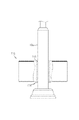
図1は、本発明の好適な実施形態によるスマート太陽光発電システムの外観を示す正面図であり、図2は、図1の側面図であり、図3は、本発明の好適な実施形態によるスマート太陽光発電システムの機能的構成を示すブロック図である。 1 is a front view showing the appearance of a smart photovoltaic power generation system according to a preferred embodiment of the present invention, FIG. 2 is a side view of FIG. 1, and FIG. 3 is a preferred embodiment of the present invention It is a block diagram showing a functional configuration of a smart photovoltaic power generation system.
図1乃至図3を参照する。本発明の好適な実施形態によるスマート太陽光発電システムは、太陽光発電の敷地の地面に立設固定されるポール10と、ポール10の上端に設置される太陽光パネル20と、地面の下に埋め込まれてポール10の下端と連結されるウェイトブロック70と、太陽光パネル20の下部に設置され、太陽光パネル20を所定の速度で徐々に回転することにより発電効率を高める回転装置30と、回転装置を駆動制御するマイコン40と、を備える。
Please refer to FIGS. A smart solar power generation system according to a preferred embodiment of the present invention includes a
ポール10は垂直に立設され、下端がウェイトブロック70の上端にアンカーボルト等の締結手段で固設される。好ましくは、ポール10は、通常の街灯柱のような丸い外周面を有する金属製の管状体であり、他の様々な材料で様々な形態で構成され得る。
The
太陽光発電の敷地が山地や林野、休耕地等の樹木が存在する場所である場合、太陽光発電システムの施工時にポール10の周りに樹木が位置するように、複数のポール10を所定間隔で離間して配置してもよい。また、本発明が適用可能な太陽光発電の敷地として、少なくとも一つ以上のウェイトブロック70を埋設し、前記ウェイトブロック70上にポール10を立設できる少ない空きスペースを確保できる限り、工場周辺や住宅街、公園周辺などの様々な場所を採用することができる。
If the site for photovoltaic power generation is a place with trees such as mountains, forests, and fallow lands, a plurality of
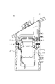
太陽光パネル20は、ポール10の上端に設置され、太陽光電気を発生する。太陽光パネル20は、回転装置の上端に傾斜するように形成された支持板(図4の31)の上に載せられて地面に対して傾斜するように設置される。太陽光パネル20の設置角度は支持板31の傾斜角によって決定される。支持板31の中心には、回転装置30の内部空間を開閉するための防水カバー32が着脱可能に設置される。
A
回転装置30は、ポール10の上部に設置されて太陽光パネル20に回転力を与える。図4に示すように、回転装置30は、所定角度傾斜して配置された太陽光パネル20の背面に結合される支持板31と、支持板31の下部に連結される第1管状体33と、第1管状体33の下部に組み立てられ、下端がポール10に固定される第2管状体34と、第2管状体34の内部に設置されて第1管状体33に回転力を与える駆動モータ35と、駆動モータ35を制御して太陽光パネル20を所定時間一方向に等速回転させるマイコン40と、を備える。
The
第1管状体33は、上面に支持板31が位置し、円周面を有するパイプ状の構造物である。第1管状体33と支持板31とを一体に構成してもよく、または、第1管状体33の上端に支持板31を溶接により一体化してもよい。
The first
第2管状体34は、第1管状体33の下部に位置するように組み立てられ、円周面を有するパイプ状の構造物である。第2管状体34の下端には、ポール10の上端のパイプ構造を挿入可能な環状のスロットを追加してもよい。中空にポールが挿入されることにより第2管状体34がポール10の上端に固定される。
The second
第1管状体33と第2管状体34との間には、所定の軸受が介装されていてもよい。前記軸受は、第1管状体33に一体に回転可能に連結される上リングと、前記上リングの下部に組み立てられ、第2管状体34に連結される下リングとを備え、前記上リングと下リングとの間に多数のボールを介在させてもよい。また、前記上リング又は前記下リングの周囲に沿ってギヤ歯を形成し、駆動モータ35は、前記ギヤ歯に噛合可能な所定のギヤを介して第1管状体33に回転力を与える。
A predetermined bearing may be interposed between the first
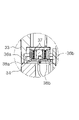
図5に示すように、第1管状体33と第2管状体34との接触部には、電源及び/又は信号を伝達するための第1接点36a、36bと第2接点38a、38bとが設けられる。第1接点36a、36b及び第2接点38a、38bは、それぞれ少なくとも一つ以上の導体リングで構成され、第1管状体33及び第2管状体34にそれぞれ固定され、上下方向に対向して配置される。
第1管状体33が第2管状体34に対して回転する間、前記第1接点36a、36bは、コイルばね37により弾性的に下方に付勢され、第2接点38a、38bと接触する状態を連続的に維持する。あるいは、第1接点と第2接点とのいずれか一方をロール状に構成し、他方を前記ロールが転がりうる導体リングとして構成するので、第1接点と第2接点とは、第1管状体33が回転する際に相対的に転がりながら接触状態を維持する。
As shown in FIG. 5, the contact portion between the first
While the first
または、図6に示すように、第1管状体33と第2管状体34との間には、電源又は信号を伝達するための電線39を接続してもよい。
Alternatively, as shown in FIG. 6, an
図7に示すように、回転装置30は、第1管状体33に実質的に連結される回転ギヤ62と、第2管状体34に実質的に連結される固定ギヤ61と、回転ギヤ62に回転力を与えるために固定ギヤ61に連結される駆動モータ35と、回転ギヤ62の下部に配置され回転ギヤ62と一体に回転する回転計数板63と、固定ギヤ61に固定され、回転ギヤ62が回転する際に、回転計数板63と接触する状態を維持するリミットスイッチ60と、を備える。
As shown in FIG. 7, the rotating
回転ギヤ62は、駆動モータ35からの回転力を受けて固定ギヤ61に対して相対的に回転可能に設けられる。回転ギヤ62及び固定ギヤ61は、様々な公知のギヤアセンブリで構成され得る。
The
駆動モータ35は、第2管状体34の内部に第2管状体34と同軸に立設固定され、回転ギヤ62に回転力を与えるのが好ましい。
It is preferable that the
回転計数板63は、回転ギヤ62の下部に固定されて回転ギヤ62と共に回転し、下部には、谷(又は溝)と隆起(又は突起)構造からなる凹凸パターンが円周方向に周期的に形成される。
The
リミットスイッチ60の一方の側は固定ギヤ61に固定され、他方の側は回転計数板63に接触し、回転計数板63の回転と同時に前記凹凸パターンとの接触状態を継続的に維持する。したがって、回転計数板63が回転すると、リミットスイッチ60からON/OFF信号が繰り返し出力される。
One side of the
さらに、太陽光パネル20と回転装置30との間に、設置領域の緯度に対応するように設定された傾斜角を有するベースプレート(図示せず)を挟んでもよい。前記ベースプレートにより、太陽光パネル20の傾斜角を、異なる緯度の領域毎に異なる角度に設定して操作することができる。
Furthermore, a base plate (not shown) having an inclination angle set to correspond to the latitude of the installation area may be interposed between the
マイコン40は、照度センサ50、季節別回転設定時間、衛星通信モジュールが提供するGPS時間情報等に基づいて、太陽光パネル20の1日回転量を決定し、駆動モータ35のオンオフ制御に1日回転量を適用して回転制御を行う回転制御部41を備える。マイコン40は、回転装置30に内蔵されてもよく、ポール10に内蔵されてもよく、別の筐体に内蔵されてもよい。
The
マイコン40は、照度センサ50から出力される太陽光の照度値が所定値以上になると日が明けたことを認識し、駆動モータ35を作動させ、予め設定された回転ステップ及び/又は時間で太陽光パネル20を一方向に秒毎に徐々に回転させる。太陽の日照量を考慮して、太陽光パネル20が回転する経路を、太陽光パネル20をできるだけ太陽に対して十分に露出させるように設定することが好ましい。太陽光パネル20を所定の速度で所定時間回転させると、複雑な構造の太陽光トラッキング装置を別途使用しなくても、太陽光パネル20を一方に向けて静止状態に置く場合に比べ、太陽光発電電力量を増やすことができる。
When the illuminance value of sunlight output from the
具体的には、マイコン40の回転制御部41は、太陽の日出直前又は日出直後に、太陽光パネル20を所定の速度で回転させながら太陽光電気を発生させる第1回転モードを行う。また、マイコン40は、日没中、日没直後、又は日出直前には、日没時又は日出時に太陽光パネル20から出力される残電気を用いて太陽光パネル20の上面が東向きになるように太陽光パネル20を回転させ、太陽光パネル20を翌日の回転開始位置に移動させる第2回転モードを行う。このため、第1回転モードと第2回転モードに対するデータは、マイコン40のメモリ42に記憶される。
Specifically, the
マイコン40は、日没時又は日出時には、太陽光パネル20から出力される残電気を用いて、太陽光パネル20の上面が東向きになるように太陽光パネル20を回転させ、太陽光パネル20を翌日の回転開始位置に移動させる第2回転モードを行う。ここで、「残電気」とは、太陽光パネル20で生成され、電力が所定の電力レベルに達しないため、電力会社に送信されない残留電気を指す。日没時又は日出時に、太陽光パネル20が直接又は間接的に受ける少量の太陽光により、前記残電気が発生する。前記「回転開始位置」とは、日没後の翌日に太陽光パネル20の回転が再開する位置を指す。
At sunset or sunrise, the
本発明では、前記微量の残電気を用いて、第1回転モードが始まる回転開始位置に回転装置30を回転移動させる制御を行う。例えば、日没直後に太陽光パネル20が西に向いた所定位置で発電を終了したとき(電力会社への送電が停止された場合)、マイコン40は、太陽光パネル20から出力される残電気を用いて回転装置30を駆動し、太陽光パネル20を東方向に徐々に回転させて回転開始位置に配置させる制御を行う。
In the present invention, the small amount of residual electricity is used to control the rotational movement of the
第1管状体33と第2管状体34との間で電源及び/又は信号を伝達するために第1接点36b,36cと第2接点38b,38cとを設けた場合、太陽光パネル20を東方向に回転させる動作は、第1回転モードにおける太陽光パネル20の回転方向と同じ方向であることが好ましい。一方、第1管状体33と第2管状体34との間で電源及び/又は信号を伝達する電線39を接続する際に、太陽光パネル20を東方向に回転させる動作を、第1回転モードにおける太陽光パネル20の回転方向と逆の方向に設定し、電線39のねじれを防止する。
When the
マイコン40は、回転計数板63の回転に伴う凹凸パターンの変化によりON/OFFされるリミットスイッチ60の作動から、太陽光パネル20の回転をステップ別に(段階別に)駆動及び検知する。ここで、太陽光パネル20の回転の第1ステップは、回転計数板63の1周期、すなわち、リミットスイッチ60が、前記凹凸パターンに含まれるいずれか一つの溝に接触した後に、次の溝に接触したことをカウントすることで定義されてもよい。
The
すなわち、マイコン40は、各季節毎に異なる回転ステップ数を設定することで、太陽光パネル20の1日回転量(回転角)を異ならせるように制御してもよい。各季節の日照量を考慮する場合は、夏は最も多い(最も多く回転する)回転ステップ数を設定し、冬は最も少ない(最も少なく回転する)回転ステップ数を設定して回転制御を行うことが望ましい。具体的には、マイコン40は、回転計数板63の回転ステップ数を春秋1~11ステップ、夏季0~12ステップ、冬季2~10ステップに設定して回転制御を行う。このため、マイコン40のメモリ42には、回転ステップ設定値のデータが記憶される。
That is, the
メインコントローラ80は、それぞれのマイコン40と有線/無線通信を行い、互いに異なる太陽光パネル20及び回転装置30を統合的に管理し、全ての太陽光パネル20が実質的に同じパターンで回転するように制御する。
The
さらに、メインコントローラ80は、雨が降ったときの風向きを検知し、太陽光パネル20を雨滴の落下方向と対向する方向に回転させる制御を行う。すなわち、太陽光パネル20の表面が直接雨滴に曝されるので、太陽光パネル20の表面に堆積した微細粉塵や異物を効果的に除去することができる。
Further, the
ウェイトブロック70は、所定長さの鉄筋を挿入し、コンクリートを打設してポール10を支持するコンクリートブロックからなる。施工が完了すると、太陽発電の敷地の地盤(土砂地面)の下にウェイトブロック70が埋設される。ウェイトブロック70は、太陽発電システムを構成する複数のポールに対応して1対1で設けられ、ポール10の下端に連結される。
The
ウェイトブロック70の下部に、土砂に埋め込まれてウェイトブロック70を固定する杭(pile)を連結し、強風等によってポール10が引き抜かれるのを防止する。また、ウェイトブロック70の上面には、ポール10を固定するためのアンカーボルトが設けられる。
A pile, which is buried in earth and sand and fixed to the
複雑な構造の太陽光トラッキング装置を別途使用しないが、上記構成を有する本発明は、太陽光電気を生産する際に、太陽光パネル20を一方に向けて静止状態に置く場合に比べ、太陽光パネル20を駆動モータ35を用いて所定速度で徐々に回転させ、太陽光発電電力量を増やすことができる。
Although it does not use a separate solar tracking device with a complicated structure, the present invention with the above configuration can produce solar power more effectively than the
また、日没時又は日出時には、太陽光パネル20から出力される残電気を用いて太陽光パネル20を東向きに回転させて回転開始位置に移動させることにより、翌日の日出直後に正しい位置で太陽光発電を行うので、発電効率を高めることができる顕著な効果を有する。
In addition, at sunset or sunrise, the remaining electricity output from the
一方、本発明では、太陽光パネル20を支持するポール10の周囲の樹木をそのまま維持できるので、自然へのダメージを最小限に抑えつつ、環境に優しい太陽光発電設備を構築することができる。また、ポール10の周囲の樹木が防風林として機能するので、太陽光パネル20をより安定して設置することができる。
On the other hand, in the present invention, trees around the
施工時には、ポール10を設置する各箇所に所定の穴を掘り、ウェイトブロック70を埋設固定し、ポール10の下端をウェイトブロック70の上端に載置してアンカーボルトを用いて固定することで、施工が容易に完了する。
During construction, a predetermined hole is dug at each location where the
スマート太陽光発電システムの運転中に、回転装置30により太陽光パネル20が所定の時間と速度で一方向に回転するので、太陽光発電電力量を増やすことができる。
During operation of the smart photovoltaic power generation system, the
回転装置30は、駆動モータ35の回転力を回転ギヤ62に伝達し、第1管状体33を回転させることにより、第1管状体33の支持板31に固定された太陽光パネル20を回転させる。第1管状体33は、太陽光パネル20を安定して支持した状態でポールに固定された第2管状体34に対して回転する。第1管状体33と第2管状体34との間に所定の軸受を介在させるので、構造的に安定的で円滑な回転が可能となる。
The
回転計数板63は、回転ギヤ62の下部に固定されて回転ギヤ62と一体に回転し、リミットスイッチ60が回転計数板63の下部との接触状態を持続的に維持して、回転計数板63の凹凸パターンを検知することで、回転量をステップ別に(段階別に)検出することができる。マイコン40は、回転計数板63の回転に伴う凹凸パターンの変化によりON/OFFされるリミットスイッチ60の作動から、太陽光パネル20の回転をステップ別に駆動し、太陽光パネル20がエラーなしで秒毎に回転するか否かを検知し、制御動作に反映する。
The
上述したように、本発明によるスマート太陽光発電システムは、日没時又は日出時に太陽光パネルで生産される残電気を用いて、太陽光パネルを予め回転開始点にセットすることにより、太陽光発電の効率を向上させることができる。 As described above, the smart photovoltaic power generation system according to the present invention uses the remaining electricity produced by the photovoltaic panel at sunset or sunrise to set the photovoltaic panel in advance at the rotation start point, thereby The efficiency of photovoltaic power generation can be improved.
また、施工が簡単なので、太陽光発電の敷地に対する選択肢の幅が広く、ポールを固定するウェイトブロック70をポール毎に局所的に埋め込むように設けるので、環境破壊を最小限に抑えつつ、環境に優しい太陽光発電設備を構築できる。特に、太陽光発電の敷地が山地や林野の場合、太陽光パネルを支えるポールの周りの樹木をそのまま維持できるので、自然への被害を最小限に抑えることができる。 In addition, since the construction is simple, there is a wide range of options for the site of photovoltaic power generation, and since the weight blocks 70 for fixing the poles are provided so as to be locally embedded in each pole, environmental damage is minimized and the environment is improved. You can build a friendly solar power generation facility. In particular, if the site for photovoltaic power generation is mountainous or forested, the trees around the poles that support the photovoltaic panels can be maintained as they are, so damage to nature can be minimized.
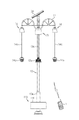
図8は、本発明の他の実施形態によるスマート太陽光発電システムの外観を示す斜視図であり、図9は図8の正面図であり、図10は図8の側面図である。 8 is a perspective view showing the appearance of a smart photovoltaic power generation system according to another embodiment of the present invention, FIG. 9 is a front view of FIG. 8, and FIG. 10 is a side view of FIG.
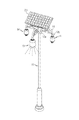
図8乃至図10を参照する。本発明の好適な実施形態によるスマート太陽光発電システムは、地面に立設されるポール10と、ポール10の上部に配置された複数の支持部材11と、支持部材11に設置された高所設置機器である昇降式照明モジュール13及び昇降式カメラモジュール14とを含む。
Please refer to FIGS. A smart photovoltaic power generation system according to a preferred embodiment of the present invention includes a
ポール10は地面から垂直に立設され、下端がアンカーボルト等の締結手段により地面に固設される。好ましくは、ポール10は、通常の街灯柱のような丸い外周面を有する金属製の管状体であり得、他の様々な材料で様々な形態で構成され得る。
The
複数の支持部材11は、ポール10の上部に位置し、ポール10の周りの前方及び側方に向かって数方向に分岐した形状で配置される。複数の支持部材11の一方の端12aは、溶接又はボルト止めによりポール10に取り付けられ、中央が上方に向かって湾曲してアーチ状を成し、他方の端12bは地面に向けて配置される。このような構造によれば、昇降式照明モジュール13の上端と昇降式カメラモジュール14の上端に各支持部材11の他方の端12bが連結されるので、各モジュール13,14を上方から保持して各モジュール13,14を安定支持でき、各モジュール13,14の周辺で支持部材11が障害物になることを防止することができる。
A plurality of support members 11 are positioned above the
前記高所設置機器として、昇降式照明モジュール13及び昇降式カメラモジュール14を用いることが好ましいが、本発明はこのような例に限らず、他の様々な機器を用いてもよい。
Although it is preferable to use the elevating
昇降式照明モジュール13は、複数の支持部材11のうち少なくとも一つの端部に設けられる。昇降式照明モジュール13は、第1昇降ケーブル13cを巻き取るドラムと、前記ドラムに回転力を与える駆動モータとを内部に有する第1本体13bと、第1昇降ケーブル13cの端部に吊り下げ連結され、上昇完了時に第1本体13bの下端に結合され、下降時には第1本体13bから分離される照明ユニット13aと、を備える。昇降照明ユニット13aは、多数のパワーLEDから構成され、Wi-Fi(登録商標)、LTE(登録商標)、ブルートゥース(登録商標)等の無線通信プロトコルをサポートする通信モジュールに接続されることが好ましい。
The elevating
昇降式カメラモジュール14は、複数の支持部材11のうち少なくとも他の一つの端部に設けられる。昇降式カメラモジュール14は、第2昇降ケーブル14cを巻き取るドラムと、ドラムに回転力を与える駆動モータとを内部に有し、上端が支持部材11の端部に固定される第2本体14bと、第2昇降ケーブル14cの端部に吊り下げ連結され、上昇完了時に第2本体14bの下端に結合され、下降時には第2本体14bから分離されるCCTVカメラ14aと、を備える。CCTVカメラ14aは、Wi-Fi、LTE、ブルートゥース等の無線通信プロトコルをサポートする通信モジュールに接続されることが好ましい。
The elevating
好ましくは、支持部材11は、一定の間隔を置いて三方向に配置される。昇降式照明モジュール13は、三方向の支持部材11のうち中間に位置する支持部材11に設置される。また、昇降式カメラモジュール14は、残りの支持部材11にそれぞれ一つずつ設置される。
Preferably, the support members 11 are arranged in three directions at regular intervals. The elevating
昇降式照明モジュール13の第1昇降ケーブル13cと昇降式カメラモジュール14の第2昇降ケーブル14cとは、ワイヤロープや電力ケーブルで構成してもよい。
The first elevating cable 13c of the elevating
本出願人が先に提出した韓国特許出願第10-2013-0070072号で開示した技術は、昇降式照明モジュール13と昇降式カメラモジュール14とにそれぞれ内蔵された第1昇降ケーブル13cと第2昇降ケーブル14cとを巻き上げ又は巻き下げするドラム及び駆動モータの技術構成として用いることができる。
The technology disclosed in Korean Patent Application No. 10-2013-0070072 previously filed by the present applicant is based on the first lifting cable 13c and the second lifting cable 13c built in the
図11に示すように、昇降式照明モジュール13の照明ユニット13aと、昇降式カメラモジュール14のCCTVカメラ14aとを、個別に昇降制御してもよい。すなわち、特定の照明ユニット13aやCCTVカメラ14aに対するメンテナンスや清掃等が必要な場合、管理者は、当該照明ユニット13aやCCTVカメラ14aのみを選択的に下げて作業を行う。あるいは、照明ユニット13a及びCCTVカメラ14aをグループとして昇降制御することも可能である。この場合、複数のCCTVカメラ14aを一括して昇降制御してもよい。また、必要に応じて、全ての照明ユニット13a及びCCTVカメラ14aを一括して同時に昇降制御することもできる。
As shown in FIG. 11, the
昇降式照明モジュール13及び昇降式カメラモジュール14に対する昇降操作は、有線又は無線通信により個別に行ってもよい。無線通信を使用する場合、Wi-FiやLTE等を無線通信仕様として使用することができる。
The elevating operation for the elevating
太陽光パネル20は、ポール10の上端に設置され、昇降式照明モジュール13及び昇降式カメラモジュール14に太陽光発電電源を供給する。昇降式照明モジュール13及び昇降式カメラモジュール14は、基本的に商用電力網から電力を受け、停電時には太陽光パネル20から非常電源を受け取るように構成されてもよい。
The
図12に示すように、太陽光パネル20は所定の角度で斜めに傾斜するように配置される。
As shown in FIG. 12, the
駆動モータ35の回転軸17は、地面に対して垂直に配置されて太陽光パネル20の裏面に連結され、太陽光パネル20は、前記駆動モータ35の回転軸17に対して傾斜するように配置される。
The rotating shaft 17 of the driving
マイコン40は、照度センサ50等と連動して駆動モータ35の作動時間及び速度を制御する。マイコン40は、照度センサ50の出力値(照度値)又は設定時間から日が暗くなったことや明るくなったことを認識する。例えば、マイコン40は、太陽の照度値が所定値以上になると日が明るくなったことを認識し、駆動モータ35を作動させ、太陽光パネル20を所定時間一方向に徐々に回転させる。太陽の日照量を考慮して、太陽光パネル20が回転する経路を、太陽光パネル20をできるだけ太陽に対して十分に露出させるように設定することが好ましい。
太陽光パネル20を所定の速度で所定時間回転させると、複雑な構造の太陽光トラッキング装置を別途使用しなくても、太陽光パネル20を一方に向けて静止状態に置く場合に比べて、太陽光発電電力量を増やすことができる。
The
Rotating the
上記のような構成を有する本発明の好適な実施形態によるスマート太陽光発電システムでは、それぞれの本体13b、14bに内蔵されたドラムの正回転駆動による第1昇降ケーブル13c及び第2昇降ケーブル14cの巻き上げにより、照明ユニット13a及びCCTVカメラ14aが上昇して、ポール10の上部に位置するそれぞれの本体13b,14bと結合されたとき、それぞれの本体13b,14bに内蔵された上部接点部と下部接点部とが互いに接触して、照明ユニット13a及びCCTVカメラ14aに電源が供給され得る。ここで、上部接点部は本体13c,14cに固定され、下部接点部は、昇降体に該当する照明ユニット13a及びCCTVカメラ14aの上端にそれぞれ固定される。
In the smart photovoltaic power generation system according to the preferred embodiment of the present invention having the configuration described above, the first lifting cable 13c and the second lifting cable 14c are driven by forward rotation of the drums built in the main bodies 13b and 14b. By winding up, the
照明ユニット13a及びCCTVカメラ14aに対して定期点検やメンテナンス、レンズ/ガラス清掃等を行いたい場合には、それぞれの本体に内蔵されたドラムに対して逆方向回転駆動を行い、第1昇降ケーブル13c及び第2昇降ケーブル14cを解いて照明ユニット13a及びCCTVカメラ14aを地上に下降させる。
When the
照明ユニット13a及びCCTVカメラ14a対するメンテナンスや清掃等が必要な場合、管理者は、照明ユニット13a及びCCTVカメラ14aを個別に下降させて作業を行う。管理者は、必要に応じて、全ての照明ユニット13a及びCCTVカメラ14aを一括して同時に昇降させる操作を行ってもよい。
When maintenance or cleaning of the
照明ユニット13a及びCCTVカメラ14aは、上昇が完了してそれぞれの本体13b,14bに結合された状態で動作する。図13に示すように、照明ユニット13aの作動のための検知センサ90は、ポール10から離間した位置にある建物の外壁100に設けられる。検知センサ90により歩行者の接近が検知されると、検知信号が昇降式照明モジュール13の照明制御部に無線送信され、照明ユニット13aが自動的に点灯するように制御される。このように、検知センサ90は、ポール10から離間した位置に配置されるので、歩行者がポール10のいずれの側にいても誤りなく接近を検知することができる。
または、検知センサ90は、図19に示すように、ポール10の外面の周りに固定される所定のリング状の装着検知センサ90であり、歩行者が検知されると、検知センサ90は、それに対応する検知信号を昇降式照明モジュール13に無線送信する。このとき、無線通信仕様としてWi-Fi、LTE、ブルートゥース等を用いることができる。
The
Alternatively, the
昇降式照明モジュール13に内蔵された照明制御部(図示せず)は、検知センサ90から検知信号が出力された場合に、照明ユニット13aを選択的に点灯(ターンオン:turn on)させる制御を行う。好ましくは、昇降式照明モジュール13の照明制御部は、歩行者の接近や移動が検知されると照明ユニット13aを点灯させ、所定時間が経過すると自動的に消灯させる自動ON/OFF制御を行うことができる。このとき、ON/OFF時間は、有線・無線通信を通じて管理者から受け取って設定されてもよい。
A lighting controller (not shown) built in the elevating
さらに、前記照明制御部は、歩行者の接近が検知されたとき、警告音や警告メッセージ、又は音楽を自動的に出力することができる。 Further, the lighting control unit can automatically output a warning sound, warning message, or music when an approaching pedestrian is detected.
図14は、本発明のまた他の実施形態によるスマート太陽光発電システムの外観を示す斜視図であり、図15は、図14の正面図である。 FIG. 14 is a perspective view showing the appearance of a smart solar power generation system according to still another embodiment of the present invention, and FIG. 15 is a front view of FIG.
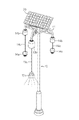
図14及び図15を参照する。スマート太陽光発電システムは、地面に立設されたポール10と、ポール10の上部に配置された複数の支持部材11と、支持部材11に設けられた昇降式照明モジュール13及び昇降式カメラモジュール14と、ポール10の上端に設けられ、昇降式照明モジュール13及びカメラに非常用電源を供給する太陽光パネル20と、ポール10の下端から所定の高さに設置されてシート面111を提供する円形シート部材110と、を備える。図面において、上記の実施形態と同じ参照符号は同じ構成要素成を示すので、その詳細な説明は省略する。
Please refer to FIGS. 14 and 15 . The smart photovoltaic power generation system includes a
円形シート部材110は、ポール10の下パイプ10aの下端から所定の高さでポール10の周囲に円形状に配置され、高さよりも大きな直径を有し、複数のユーザが同時に座り得る円形のシート面111を備えた円柱状の構造物である。
The
円形シート部材110の一側又は下パイプ10bの一側には、ユーザの接近又は着座を検知する検知センサ(図示せず)を取り付けてもよい。上記の実施形態と同様に、前記検知センサは、周辺の建物の外壁100に取り付けられてもよい。
A detection sensor (not shown) may be attached to one side of the
円形シート部材110には内部空間が設けられ、この内部空間は、円形の外面にヒンジ結合されたドア112によって開閉される。円形シート部材110の内部空間には、非常用電源を供給する所定のバッテリやコントローラ等の湿気に弱い機器を収容してもよい。したがって、円形シート部材110は、着座に加え、電子機器の浸水を防止する手段として用いられる。着座機能と浸水防止機能とを兼ね備えるため、円形シート部材110は、地面から数~数十cm離れた高さの下パイプ10bに固定される。
A
図16に示すように、円形シート部材110は、下パイプ10aの外周面を取り囲むように締め付けられた固定パイプ113の外側に挿入された後、ボルト締め又は溶接により固定される。このとき、円形シート部材110を、ポール10から分離された下パイプ10bの上から下に向けて挿入して締め付けるのが好ましい。
固定パイプ113の下端には、円形シート部材110の下端を支持するために、他の部分に比べて相対的に大きい外径を有する係止突起114が設けられることが好ましい。または、固定パイプ113を下部に向かって徐々に拡径するテーパ状に構成して、円形シート部材110が所定の位置からそれ以上下がらないように固定することも可能である。
As shown in FIG. 16, the
Preferably, the lower end of the fixed
昇降式照明モジュール13の照明制御部は、検知センサ90によりユーザの接近又は着座が検知されたとき、照明ユニット13aを自動的に点灯させる制御を行う。本発明の応用例によれば、昇降式照明モジュール13の照明制御部と、周辺のポール10に設けられた照明制御部とが互いに通信し、歩行者の動き(経路)を追跡し、隣接する照明ユニット13aを順次点灯させるように構成されてもよい。
The lighting controller of the elevating
図17は、図15の昇降ケーブル13c,14cに吊り下げられた照明ユニット13a及びCCTVカメラ14aをそれぞれ下降させた状態を示す斜視図である。上記の実施形態と同様に、照明ユニット13a及びCCTVカメラ14aに対するメンテナンスや清掃等が必要な場合、管理者は、照明ユニット13a及びCCTVカメラ14aを個別に下降させて作業を行う。管理者は、必要に応じて、照明ユニット13a及びCCTVカメラ14aをグループとして同時に昇降させる方式で作業を行ってもよい。
FIG. 17 is a perspective view showing a state in which the
CCTVカメラ14a及び照明ユニット13aの昇降操作は、所定の無線リモコン1で行ってもよい。
The CCTV camera 14a and the
さらに、ポール10又は支持部材11には、CCTVカメラ14aが撮影した映像を示すCCTVモニタ(図18の120)が設けられてもよい。CCTVモニタ120は、ハウジングが防水処理された液晶ディスプレイで構成されることが好ましい。
Furthermore, the
上述したように、本発明によるスマート太陽光発電システムでは、昇降式照明モジュール13と昇降式カメラモジュール14とをそれぞれの昇降ケーブル13c,14cを用いて個別に又は一括して昇降させることができるので、清掃や機器メンテナンス等の作業を便利に行うことができる。
As described above, in the smart photovoltaic power generation system according to the present invention, the elevating
また、歩行者の接近を検知するための検知センサ90の設置構造が改善されるので、既存の設備とは異なり、歩行者検知ブラインドスポットが発生せず、太陽光発電の効率を高めることができ、更に、円シート部材110によりユーザの着座と浸水防止の利便性を提供することができるという顕著な効果を有する。
In addition, since the installation structure of the
以上のように、本発明は、限定された実施形態及び図面によって説明されたが、これらによって限定されるものではなく、本発明の技術分野における通常の知識を有する者によって本発明の技術思想及び後述する特許請求の範囲の均等範囲内において様々な修正及び変形が可能であるということは言うまでもない。 As described above, the present invention has been described with limited embodiments and drawings, but it is not limited by these, and the technical ideas and concepts of the present invention can be understood by those having ordinary knowledge in the technical field of the present invention. It goes without saying that various modifications and variations are possible within the equivalent scope of the claims described later.
本発明を適用する場合、日没時又は日出時に太陽光パネルで生産される残電気を用いて、太陽光パネルを予め回転開始点にセットすることにより、太陽光発電の効率を向上させることができる。 When applying the present invention, the efficiency of photovoltaic power generation is improved by setting the photovoltaic panel in advance at the rotation start point using the residual electricity produced by the photovoltaic panel at sunset or sunrise. can be done.
また、太陽光パネルを用いて昇降式照明モジュール及び昇降式カメラモジュールに電源を供給し、昇降式照明モジュール及び昇降式カメラモジュールを、それぞれの昇降ケーブルを用いて個別又は一括で昇降させることができるので、清掃や機器メンテナンス等の作業を便利に行うことができ、歩行者の接近検知用センサの設置構造が改善されて、既存設備とは異なり、歩行者検知プラインドスポットが発生しない。 In addition, the solar panel can be used to supply power to the elevating lighting module and the elevating camera module, and the elevating lighting module and the elevating camera module can be lifted individually or collectively using the respective elevating cables. Therefore, work such as cleaning and equipment maintenance can be conveniently performed, and the installation structure of the pedestrian approach detection sensor is improved, and unlike existing equipment, pedestrian detection blind spots do not occur.
Claims (3)
前記ポールの上端に傾斜するように配置され、太陽光電気を発生させる太陽光パネル、
前記太陽光パネルの下部に設置され、前記太陽光パネルに回転力を与える回転装置、及び、
前記回転装置を駆動制御し、日出後に前記太陽光パネルを所定速度で回転させながら太陽光電気を生産する第1回転モードと、日没時又は日出時に前記太陽光パネルから出力される残電気を用いて前記太陽光パネルの上面が東向きになるように前記太陽光パネルを回転させて回転開始位置に移動させる第2回転モードと、を行うマイコン、を備え、
前記回転装置は、前記太陽光パネルの下部に連結される第1管状体と、前記ポールの上端に固定される第2管状体と、前記第1管状体と連結される回転ギヤと、前記第2管状体に連結される固定ギヤと、前記固定ギヤに設けられ、前記回転ギヤに回転力を与える駆動モータと、を備え、
前記第1管状体と前記第2管状体との接触部には、前記回転ギヤの回転時に互いに接触状態を維持して電源又は信号を伝達する第1接点と第2接点とが設けられ、
前記マイコンは、前記第1回転モード及び前記第2回転モードを行う際に、前記太陽光パネルを一方向にのみ回転させ、
前記回転ギヤの下部に配置され、凹凸パターンが円周方向に周期的に形成される回転計数板と、
前記固定ギヤに固定され、前記回転ギヤの回転時に前記回転計数板との接触状態を維持するリミットスイッチと、を備えることを特徴とする、
スマート太陽光発電システム。 A pole that is erected and fixed on the ground,
a solar panel arranged in a slanting manner on the upper end of the pole to generate solar electricity;
a rotating device installed at the bottom of the solar panel and applying a rotating force to the solar panel; and
A first rotation mode in which the rotation device is driven and controlled to rotate the solar panel at a predetermined speed after sunrise to produce solar electricity, and a residual output from the solar panel at sunset or sunrise. a microcomputer that performs a second rotation mode in which the solar panel is rotated using electricity so that the upper surface of the solar panel faces east and is moved to a rotation start position;
The rotating device includes a first tubular body connected to the lower part of the solar panel, a second tubular body fixed to the upper end of the pole, a rotating gear connected to the first tubular body, and the first tubular body. 2 comprising a fixed gear connected to the tubular body, and a drive motor provided in the fixed gear for applying rotational force to the rotating gear,
A contact portion between the first tubular body and the second tubular body is provided with a first contact and a second contact that maintain contact with each other during rotation of the rotary gear and transmit power or a signal,
The microcomputer rotates the solar panel only in one direction when performing the first rotation mode and the second rotation mode ,
a rotating counter plate disposed below the rotating gear and having an uneven pattern periodically formed in a circumferential direction;
a limit switch that is fixed to the fixed gear and maintains contact with the rotation counter plate when the rotary gear rotates ,
Smart solar power system.
Applications Claiming Priority (3)
| Application Number | Priority Date | Filing Date | Title |
|---|---|---|---|
| KR1020180173998A KR102037423B1 (en) | 2018-12-31 | 2018-12-31 | Multi functional pole system having lifting apparatus for highly mounted equipment |
| KR10-2018-0173998 | 2018-12-31 | ||
| PCT/KR2019/016028 WO2020141725A1 (en) | 2018-12-31 | 2019-11-21 | Smart solar power generation system |
Publications (2)
| Publication Number | Publication Date |
|---|---|
| JP2022514829A JP2022514829A (en) | 2022-02-16 |
| JP7202583B2 true JP7202583B2 (en) | 2023-01-12 |
Family
ID=68421945
Family Applications (1)
| Application Number | Title | Priority Date | Filing Date |
|---|---|---|---|
| JP2021533289A Active JP7202583B2 (en) | 2018-12-31 | 2019-11-21 | smart solar power system |
Country Status (6)
| Country | Link |
|---|---|
| US (1) | US20220085751A1 (en) |
| EP (1) | EP3907881A4 (en) |
| JP (1) | JP7202583B2 (en) |
| KR (1) | KR102037423B1 (en) |
| CN (1) | CN113196648A (en) |
| WO (1) | WO2020141725A1 (en) |
Families Citing this family (9)
| Publication number | Priority date | Publication date | Assignee | Title |
|---|---|---|---|---|
| WO2020141742A1 (en) * | 2018-12-31 | 2020-07-09 | 신정훈 | Single axis-driven solar energy generation system having sloped structure |
| KR102435588B1 (en) | 2020-04-07 | 2022-08-23 | 신정훈 | Rotation device for pole system of solar power system |
| CN112097202B (en) * | 2020-09-04 | 2022-08-26 | 深圳市鑫盛洋光电科技有限公司 | Integrated solar LED street lamp |
| CN112682751B (en) * | 2021-01-06 | 2022-08-19 | 广东启克光电有限公司 | Energy-saving and environment-friendly lighting equipment based on new energy |
| KR102477381B1 (en) | 2021-01-30 | 2022-12-14 | 신정훈 | Solar cell type secure pole system having rest area chair |
| US20230057103A1 (en) * | 2021-08-18 | 2023-02-23 | Ford Global Technologies, Llc | Remote deployable, powered, wireless edge-device |
| US20230291984A1 (en) * | 2022-03-14 | 2023-09-14 | Johnson Controls Tyco IP Holdings LLP | Methods and apparatuses for installing an automatic mounting assembly |
| CN115218155A (en) * | 2022-08-09 | 2022-10-21 | 江苏日月星辰光电科技有限公司 | Intelligent networking wind-solar hybrid new energy street lamp |
| USD1008510S1 (en) * | 2022-12-16 | 2023-12-19 | Qixiang ZHONG | Solar street light |
Citations (6)
| Publication number | Priority date | Publication date | Assignee | Title |
|---|---|---|---|---|
| JP3138252U (en) | 2007-10-12 | 2007-12-27 | 四国プラスチックス株式会社 | Device with solar tracking panel |
| KR101023014B1 (en) | 2009-11-03 | 2011-03-24 | 태창엔이티 주식회사 | Hybrid streetlight |
| JP2013080840A (en) | 2011-10-04 | 2013-05-02 | Shimizu Denki Co Ltd | Photovoltaic power generation system |
| JP2014116360A (en) | 2012-12-06 | 2014-06-26 | Daikin Ind Ltd | Solar panel unit |
| US20150236639A1 (en) | 2012-09-14 | 2015-08-20 | Commissariat A L'energie Atomique Et Aux Energies Alternatives | Solar receiver module for a concentrated photovoltaic (cpv) power plant |
| JP2017028907A (en) | 2015-07-24 | 2017-02-02 | 裕 玉浦 | Tracking solar power generation device and control method therefor |
Family Cites Families (27)
| Publication number | Priority date | Publication date | Assignee | Title |
|---|---|---|---|---|
| KR20060011286A (en) * | 2004-07-30 | 2006-02-03 | 김형진 | Intelligent sun position measurement systems |
| TW200951385A (en) * | 2008-06-05 | 2009-12-16 | Hong-Wen Zheng | Quasi-uniaxial sun-tracking control method and device of solar energy panel |
| US20120174963A1 (en) * | 2008-11-01 | 2012-07-12 | Thompson Bruce A | Clock Operated Step Function Solar Tracker |
| DE102009022876A1 (en) * | 2009-05-27 | 2010-12-30 | Hista Elektro-Anlagenbau Gmbh | Tracking unit and solar panel or photovoltaic unit |
| KR101037093B1 (en) * | 2009-07-24 | 2011-05-26 | 이화랑 | Street light control device |
| KR101064714B1 (en) | 2009-09-03 | 2011-09-14 | 주식회사 디엠에스 | Photo voltaic power generation system |
| KR101136543B1 (en) * | 2009-11-19 | 2012-04-17 | 호남대학교 산학협력단 | Tracking Photovoltaic System |
| KR100984259B1 (en) * | 2009-12-23 | 2010-09-30 | (주) 파루 | Multi led street-lamp |
| KR101046412B1 (en) * | 2010-09-02 | 2011-07-04 | 조규택 | Street light whit bench |
| KR101181829B1 (en) * | 2010-12-03 | 2012-09-11 | 주식회사 포스코 | Apparatus and method for controlling injection of alloy iron |
| KR20120061318A (en) * | 2010-12-03 | 2012-06-13 | 이충동 | Solar light tracking security liht control apparatus and method |
| KR101362254B1 (en) | 2011-12-19 | 2014-02-13 | 한국건설기술연구원 | A street tree box having improved non-point pollutant source disposal properties |
| US9236751B2 (en) * | 2012-03-09 | 2016-01-12 | Aspect Solar Pte Ltd | Portable modular sun-tracking solar energy receiver system |
| CN104870910B (en) * | 2012-11-28 | 2018-11-23 | Imo控股有限责任公司 | Tracking device, have can surround at least one axis trimming, for assembling at least one reception structure to the element of sensitive to electromagnetic waves with the preferred orientations on ray technology |
| US9553481B2 (en) * | 2013-02-28 | 2017-01-24 | Goal Zero Llc | Solar-powered lighting device and charging system |
| KR101479697B1 (en) * | 2014-04-11 | 2015-01-07 | (주)오티에스 | Auto-Lift Equipment for CCTV Camera Maintenance |
| KR101474996B1 (en) * | 2014-08-22 | 2014-12-22 | 주식회사 아이티아이씨앤씨 | Monitoring camera apparatus using solar energy |
| JP6492458B2 (en) * | 2014-08-25 | 2019-04-03 | 住友電気工業株式会社 | Photovoltaic power generation system and panel cleaning method |
| CN105698108A (en) * | 2014-11-26 | 2016-06-22 | 西安博昱新能源有限公司 | Solar LED street lamp |
| KR20160086729A (en) | 2015-01-12 | 2016-07-20 | 김한식 | The sunbeam module and method in which I installed in the rice paddy |
| PL3115687T3 (en) * | 2015-07-06 | 2018-11-30 | Reel Tech Co. Ltd. | Lifting apparatus for highly mounted equipment |
| JP6028316B1 (en) * | 2016-02-23 | 2016-11-16 | 貴弘 中井 | Solar panel power generator and method for adjusting the inclination angle of a solar panel portion in the solar panel power generator |
| CN105841087A (en) * | 2016-06-07 | 2016-08-10 | 南京工业职业技术学院 | Intelligent street lamp |
| CN206112802U (en) * | 2016-08-30 | 2017-04-19 | 天津源盛新能源科技有限公司 | Increase street lamp that solar energy power generation is rateed and solar energy and wind energy generates electricity in turn |
| KR101737380B1 (en) * | 2016-12-16 | 2017-05-22 | 송무상 | Monitoring system using auto-lift, camera and detection device |
| CN107017829A (en) * | 2017-05-23 | 2017-08-04 | 深圳市洲明科技股份有限公司 | Device of solar generating and illuminator |
| CN208158486U (en) * | 2018-04-18 | 2018-11-27 | 成都顶力能源技术服务有限公司 | The unattended electricity generating and supplying system of solar energy under oil and gas industry low light intensities |
-
2018
- 2018-12-31 KR KR1020180173998A patent/KR102037423B1/en active IP Right Grant
-
2019
- 2019-11-21 EP EP19907928.6A patent/EP3907881A4/en active Pending
- 2019-11-21 JP JP2021533289A patent/JP7202583B2/en active Active
- 2019-11-21 US US17/413,951 patent/US20220085751A1/en active Pending
- 2019-11-21 CN CN201980084381.7A patent/CN113196648A/en active Pending
- 2019-11-21 WO PCT/KR2019/016028 patent/WO2020141725A1/en unknown
Patent Citations (6)
| Publication number | Priority date | Publication date | Assignee | Title |
|---|---|---|---|---|
| JP3138252U (en) | 2007-10-12 | 2007-12-27 | 四国プラスチックス株式会社 | Device with solar tracking panel |
| KR101023014B1 (en) | 2009-11-03 | 2011-03-24 | 태창엔이티 주식회사 | Hybrid streetlight |
| JP2013080840A (en) | 2011-10-04 | 2013-05-02 | Shimizu Denki Co Ltd | Photovoltaic power generation system |
| US20150236639A1 (en) | 2012-09-14 | 2015-08-20 | Commissariat A L'energie Atomique Et Aux Energies Alternatives | Solar receiver module for a concentrated photovoltaic (cpv) power plant |
| JP2014116360A (en) | 2012-12-06 | 2014-06-26 | Daikin Ind Ltd | Solar panel unit |
| JP2017028907A (en) | 2015-07-24 | 2017-02-02 | 裕 玉浦 | Tracking solar power generation device and control method therefor |
Also Published As
| Publication number | Publication date |
|---|---|
| KR102037423B1 (en) | 2019-10-28 |
| EP3907881A1 (en) | 2021-11-10 |
| US20220085751A1 (en) | 2022-03-17 |
| JP2022514829A (en) | 2022-02-16 |
| WO2020141725A1 (en) | 2020-07-09 |
| CN113196648A (en) | 2021-07-30 |
| EP3907881A4 (en) | 2023-05-10 |
Similar Documents
| Publication | Publication Date | Title |
|---|---|---|
| JP7202583B2 (en) | smart solar power system | |
| CN107455871B (en) | Intelligent sun-shading and rain-sheltering device | |
| KR102088793B1 (en) | External Environment Responsive Surveillance Camera | |
| KR101056192B1 (en) | A solar generator having an angle control device | |
| KR101300025B1 (en) | Remote control for street lamp | |
| KR100980688B1 (en) | Sunshade with generation and photovoltaic power generation device with building as one body | |
| KR20210070094A (en) | Solar energy generation system having two-axis driving structure | |
| KR20210070085A (en) | Pole type solar energy generation system | |
| US20140062188A1 (en) | Solar Retrofit Pole | |
| WO2020141742A1 (en) | Single axis-driven solar energy generation system having sloped structure | |
| KR20200099854A (en) | shelter having independent electric power system | |
| CN106130459A (en) | A kind of photovoltaic bracket realizing automatic tracing sunlight optimized incidence | |
| JP2010113815A (en) | Outdoor illumination device | |
| JP2002134777A (en) | Solar cell panel light collector | |
| WO2020141743A1 (en) | Dual axis-driven solar energy generation system | |
| KR102159445B1 (en) | Multi functional pole system having lifting apparatus for highly mounted equipment including rotable solar cell panel | |
| KR200427302Y1 (en) | A multipurpose street light | |
| KR102159446B1 (en) | Rotation device for pole system | |
| KR102176010B1 (en) | Environment friendly solar energy generation system | |
| KR20210070102A (en) | One-axis driving type solar energy generation system having gradient structure | |
| KR100751040B1 (en) | Solar cell street-lamp with top of pole mounting structure | |
| KR102271287B1 (en) | Smart solar energy generation system | |
| JP6877807B1 (en) | Elevating shelter housing | |
| JP5816888B1 (en) | Solar power generation equipment | |
| KR102477381B1 (en) | Solar cell type secure pole system having rest area chair |
Legal Events
| Date | Code | Title | Description |
|---|---|---|---|
| A621 | Written request for application examination |
Free format text: JAPANESE INTERMEDIATE CODE: A621 Effective date: 20210611 |
|
| A977 | Report on retrieval |
Free format text: JAPANESE INTERMEDIATE CODE: A971007 Effective date: 20220622 |
|
| A131 | Notification of reasons for refusal |
Free format text: JAPANESE INTERMEDIATE CODE: A131 Effective date: 20220705 |
|
| A521 | Request for written amendment filed |
Free format text: JAPANESE INTERMEDIATE CODE: A523 Effective date: 20220719 |
|
| A131 | Notification of reasons for refusal |
Free format text: JAPANESE INTERMEDIATE CODE: A131 Effective date: 20221004 |
|
| A521 | Request for written amendment filed |
Free format text: JAPANESE INTERMEDIATE CODE: A523 Effective date: 20221013 |
|
| TRDD | Decision of grant or rejection written | ||
| A01 | Written decision to grant a patent or to grant a registration (utility model) |
Free format text: JAPANESE INTERMEDIATE CODE: A01 Effective date: 20221206 |
|
| A61 | First payment of annual fees (during grant procedure) |
Free format text: JAPANESE INTERMEDIATE CODE: A61 Effective date: 20221216 |
|
| R150 | Certificate of patent or registration of utility model |
Ref document number: 7202583 Country of ref document: JP Free format text: JAPANESE INTERMEDIATE CODE: R150 |