KR20210044772A - Closely spaced flat sheet submerged membranes and fine foam aeration - Google Patents
Closely spaced flat sheet submerged membranes and fine foam aeration Download PDFInfo
- Publication number
- KR20210044772A KR20210044772A KR1020217003259A KR20217003259A KR20210044772A KR 20210044772 A KR20210044772 A KR 20210044772A KR 1020217003259 A KR1020217003259 A KR 1020217003259A KR 20217003259 A KR20217003259 A KR 20217003259A KR 20210044772 A KR20210044772 A KR 20210044772A
- Authority
- KR
- South Korea
- Prior art keywords
- membranes
- less
- membrane
- face
- spacing
- Prior art date
Links
- 239000012528 membrane Substances 0.000 title claims abstract description 170
- 238000005273 aeration Methods 0.000 title abstract description 13
- 239000006260 foam Substances 0.000 title description 22
- 238000005276 aerator Methods 0.000 claims description 44
- 238000000034 method Methods 0.000 claims description 25
- XLYOFNOQVPJJNP-UHFFFAOYSA-N water Substances O XLYOFNOQVPJJNP-UHFFFAOYSA-N 0.000 claims description 17
- 230000008569 process Effects 0.000 claims description 11
- 238000001914 filtration Methods 0.000 claims description 9
- 238000005374 membrane filtration Methods 0.000 claims 8
- 125000006850 spacer group Chemical group 0.000 abstract description 8
- 239000007787 solid Substances 0.000 abstract description 5
- 239000002028 Biomass Substances 0.000 abstract description 2
- QVGXLLKOCUKJST-UHFFFAOYSA-N atomic oxygen Chemical compound [O] QVGXLLKOCUKJST-UHFFFAOYSA-N 0.000 abstract description 2
- 229910052760 oxygen Inorganic materials 0.000 abstract description 2
- 239000001301 oxygen Substances 0.000 abstract description 2
- 239000000356 contaminant Substances 0.000 abstract 1
- 239000003570 air Substances 0.000 description 18
- 239000012466 permeate Substances 0.000 description 18
- 230000035699 permeability Effects 0.000 description 15
- 230000004907 flux Effects 0.000 description 14
- 239000007788 liquid Substances 0.000 description 8
- 238000004140 cleaning Methods 0.000 description 5
- 239000000758 substrate Substances 0.000 description 5
- 239000010802 sludge Substances 0.000 description 4
- 239000012510 hollow fiber Substances 0.000 description 3
- 238000001471 micro-filtration Methods 0.000 description 3
- 238000000108 ultra-filtration Methods 0.000 description 3
- 230000000694 effects Effects 0.000 description 2
- 238000007654 immersion Methods 0.000 description 2
- 239000011259 mixed solution Substances 0.000 description 2
- 238000012856 packing Methods 0.000 description 2
- 239000011148 porous material Substances 0.000 description 2
- 238000000926 separation method Methods 0.000 description 2
- 229920000742 Cotton Polymers 0.000 description 1
- 238000010521 absorption reaction Methods 0.000 description 1
- 238000011001 backwashing Methods 0.000 description 1
- 230000009286 beneficial effect Effects 0.000 description 1
- 230000008901 benefit Effects 0.000 description 1
- 229910000278 bentonite Inorganic materials 0.000 description 1
- 239000000440 bentonite Substances 0.000 description 1
- SVPXDRXYRYOSEX-UHFFFAOYSA-N bentoquatam Chemical compound O.O=[Si]=O.O=[Al]O[Al]=O SVPXDRXYRYOSEX-UHFFFAOYSA-N 0.000 description 1
- 230000005540 biological transmission Effects 0.000 description 1
- 238000005266 casting Methods 0.000 description 1
- 238000009792 diffusion process Methods 0.000 description 1
- 239000004744 fabric Substances 0.000 description 1
- 230000001939 inductive effect Effects 0.000 description 1
- 238000004519 manufacturing process Methods 0.000 description 1
- 239000000463 material Substances 0.000 description 1
- 244000005700 microbiome Species 0.000 description 1
- 230000004048 modification Effects 0.000 description 1
- 238000012986 modification Methods 0.000 description 1
- 238000010137 moulding (plastic) Methods 0.000 description 1
- 239000004033 plastic Substances 0.000 description 1
- 229920000642 polymer Polymers 0.000 description 1
- 238000004382 potting Methods 0.000 description 1
- 238000011084 recovery Methods 0.000 description 1
- 239000000725 suspension Substances 0.000 description 1
- 239000002351 wastewater Substances 0.000 description 1
Images


Classifications
-
- B—PERFORMING OPERATIONS; TRANSPORTING
- B01—PHYSICAL OR CHEMICAL PROCESSES OR APPARATUS IN GENERAL
- B01D—SEPARATION
- B01D63/00—Apparatus in general for separation processes using semi-permeable membranes
- B01D63/08—Flat membrane modules
- B01D63/082—Flat membrane modules comprising a stack of flat membranes
- B01D63/0821—Membrane plate arrangements for submerged operation
-
- B—PERFORMING OPERATIONS; TRANSPORTING
- B01—PHYSICAL OR CHEMICAL PROCESSES OR APPARATUS IN GENERAL
- B01D—SEPARATION
- B01D63/00—Apparatus in general for separation processes using semi-permeable membranes
- B01D63/08—Flat membrane modules
- B01D63/082—Flat membrane modules comprising a stack of flat membranes
- B01D63/0822—Plate-and-frame devices
-
- B—PERFORMING OPERATIONS; TRANSPORTING
- B01—PHYSICAL OR CHEMICAL PROCESSES OR APPARATUS IN GENERAL
- B01D—SEPARATION
- B01D63/00—Apparatus in general for separation processes using semi-permeable membranes
- B01D63/14—Pleat-type membrane modules
-
- B—PERFORMING OPERATIONS; TRANSPORTING
- B01—PHYSICAL OR CHEMICAL PROCESSES OR APPARATUS IN GENERAL
- B01D—SEPARATION
- B01D65/00—Accessories or auxiliary operations, in general, for separation processes or apparatus using semi-permeable membranes
- B01D65/02—Membrane cleaning or sterilisation ; Membrane regeneration
-
- B—PERFORMING OPERATIONS; TRANSPORTING
- B01—PHYSICAL OR CHEMICAL PROCESSES OR APPARATUS IN GENERAL
- B01D—SEPARATION
- B01D65/00—Accessories or auxiliary operations, in general, for separation processes or apparatus using semi-permeable membranes
- B01D65/08—Prevention of membrane fouling or of concentration polarisation
-
- C—CHEMISTRY; METALLURGY
- C02—TREATMENT OF WATER, WASTE WATER, SEWAGE, OR SLUDGE
- C02F—TREATMENT OF WATER, WASTE WATER, SEWAGE, OR SLUDGE
- C02F3/00—Biological treatment of water, waste water, or sewage
- C02F3/02—Aerobic processes
- C02F3/12—Activated sludge processes
- C02F3/1236—Particular type of activated sludge installations
- C02F3/1268—Membrane bioreactor systems
- C02F3/1273—Submerged membrane bioreactors
-
- B—PERFORMING OPERATIONS; TRANSPORTING
- B01—PHYSICAL OR CHEMICAL PROCESSES OR APPARATUS IN GENERAL
- B01D—SEPARATION
- B01D2313/00—Details relating to membrane modules or apparatus
- B01D2313/26—Specific gas distributors or gas intakes
-
- B—PERFORMING OPERATIONS; TRANSPORTING
- B01—PHYSICAL OR CHEMICAL PROCESSES OR APPARATUS IN GENERAL
- B01D—SEPARATION
- B01D2315/00—Details relating to the membrane module operation
- B01D2315/06—Submerged-type; Immersion type
-
- B—PERFORMING OPERATIONS; TRANSPORTING
- B01—PHYSICAL OR CHEMICAL PROCESSES OR APPARATUS IN GENERAL
- B01D—SEPARATION
- B01D2321/00—Details relating to membrane cleaning, regeneration, sterilization or to the prevention of fouling
- B01D2321/18—Use of gases
- B01D2321/185—Aeration
-
- B—PERFORMING OPERATIONS; TRANSPORTING
- B01—PHYSICAL OR CHEMICAL PROCESSES OR APPARATUS IN GENERAL
- B01D—SEPARATION
- B01D2325/00—Details relating to properties of membranes
- B01D2325/08—Patterned membranes
-
- C—CHEMISTRY; METALLURGY
- C02—TREATMENT OF WATER, WASTE WATER, SEWAGE, OR SLUDGE
- C02F—TREATMENT OF WATER, WASTE WATER, SEWAGE, OR SLUDGE
- C02F2303/00—Specific treatment goals
- C02F2303/16—Regeneration of sorbents, filters
-
- C—CHEMISTRY; METALLURGY
- C02—TREATMENT OF WATER, WASTE WATER, SEWAGE, OR SLUDGE
- C02F—TREATMENT OF WATER, WASTE WATER, SEWAGE, OR SLUDGE
- C02F3/00—Biological treatment of water, waste water, or sewage
- C02F3/02—Aerobic processes
- C02F3/12—Activated sludge processes
- C02F3/20—Activated sludge processes using diffusers
- C02F3/201—Perforated, resilient plastic diffusers, e.g. membranes, sheets, foils, tubes, hoses
-
- Y—GENERAL TAGGING OF NEW TECHNOLOGICAL DEVELOPMENTS; GENERAL TAGGING OF CROSS-SECTIONAL TECHNOLOGIES SPANNING OVER SEVERAL SECTIONS OF THE IPC; TECHNICAL SUBJECTS COVERED BY FORMER USPC CROSS-REFERENCE ART COLLECTIONS [XRACs] AND DIGESTS
- Y02—TECHNOLOGIES OR APPLICATIONS FOR MITIGATION OR ADAPTATION AGAINST CLIMATE CHANGE
- Y02W—CLIMATE CHANGE MITIGATION TECHNOLOGIES RELATED TO WASTEWATER TREATMENT OR WASTE MANAGEMENT
- Y02W10/00—Technologies for wastewater treatment
- Y02W10/10—Biological treatment of water, waste water, or sewage
Abstract
침지식 멤브레인들은, 폭기(기포들이 멤브레인들을 지나 상승함)를 멤브레인 표면을 세척하기 위한 수단으로서 사용하고 그리고 멤브레인 표면을 고형물들, 또는 오염물들로부터 깨끗하게 유지하여, 연속적인 그리고 효과적인 작동을 허용한다. 평탄 시트 멤브레인들의 모듈에서, 미세 거품 폭기는 멤브레인 시트들 사이에서 공간을 형성하고 그리고 유지하는데 사용된다. 거품들은 시트들이 함께 접촉하고 그리고 막혀, 이에 따라 그들의 표면적 및 그들의 생산성을 감소시키는 것을 억제한다. 폭기는 산소를 바이오매스에 공급하도록 세척하기 위해 그리고 침지식 평탄 시트 멤브레인들의 작동 표면적을 유지하기 위해 스페이서로서 사용될 수 있다. 멤브레인 시트들 사이의 면 대 면 간격은 4mm 이하일 수 있다. 거품들은 멤브레인 시트들 사이에 면 대 면 간격의 2배보다 더 작을 수 있다.Submerged membranes use aeration (bubbles rise past the membranes) as a means to clean the membrane surface and keep the membrane surface clean from solids, or contaminants, allowing continuous and effective operation. In a module of flat sheet membranes, microbubble aeration is used to create and maintain spaces between the membrane sheets. The bubbles inhibit the sheets from contacting and clogging together, thus reducing their surface area and their productivity. Aeration can be used as a spacer to clean to supply oxygen to the biomass and to maintain the working surface area of the submerged flat sheet membranes. The face-to-face spacing between the membrane sheets may be 4 mm or less. The bubbles may be less than twice the face-to-face spacing between the membrane sheets.
Description
[0001] 본 출원은 2018년 7월 3일자로 출원된 미국 가특허 출원 일련 번호 제62/693,617호의 이익을 주장하며, 이는 인용에 의해 본원에 포함된다.[0001] This application claims the benefit of US Provisional Patent Application Serial No. 62/693,617, filed on July 3, 2018, which is incorporated herein by reference.
[0002] 본 명세서는 침지식 멤브레인들(immersed membranes)(대안적으로, 잠수식 멤브레인들(submerged membranes)로 불림) 및 침지식 멤브레인들을 작동하는 방법들에 관한 것이다.[0002] The present specification relates to immersed membranes (alternatively referred to as submerged membranes) and methods of operating immersed membranes.
[0003] 다음 내용은 아래에서 논의된 임의의 것이 공통의 일반적인 지식이거나 종래 기술로서 인용될 수 있는 할 수 있다는 것을 인정하는 것은 아니다.[0003] The following is not an admission that anything discussed below may be of common general knowledge or that may be cited as prior art.
[0004] 침지식 여과 멤브레인들은 대안적으로 플레이트(plate) 및 프레임 구성으로 불리는 평탄 시트로 제조될 수 있다. 이러한 구성에서, 멤브레인 시트의 롤은 부직포 기판의 롤 상에 주조되는 중합체 분리 층을 주조함으로써 제조된다. 멤브레인 시트의 2개의 일반적으로 직사각형 피스들이 중공형 플라스틱 프레임의 대향하는 측들 상에 그들의 모서리들에서 부착된다. 이는, 대안적으로 투과물(permeate)로 불리는 여과된 물을 수집하기 위해 중공형 내부 채널을 갖는 패널을 생성한다. 투과물은 멤브레인의 내부에 적용되는 흡입에 의해 인출된다. 수 개의 패널들은, 여과되도록 물에 침지될 수 있는 프레임 내로 나란히 미끄러진다. 여과될 물은 통상적으로 개방 탱크에 유지된다. 패널들의 내측들은 멤브레인 시트들을 통해 투과물을 인출하기 위해 펌프의 흡입 측에 연결된다. 프레임 아래로부터 제공되는 거품들은, 거품들 및 액체의 혼합된 유동이 멤브레인 표면들을 깨끗하게 유지하기 위해 패널들 사이의 수직 슬롯들을 통해 상승하는 것을 유발한다. 이러한 유형의 디바이스의 예들은, Kubota 회사에 의해 모두 소유된, 미국 특허 번호 제5,482,625호; 제5,651,888호; 제5,772,831호; 제6,287,467호; 및 제6,843,908호에서 도시된다.[0004] Submerged filtration membranes may alternatively be made of a flat sheet called a plate and frame configuration. In this configuration, a roll of membrane sheet is produced by casting a polymer separation layer that is cast on a roll of a nonwoven substrate. Two generally rectangular pieces of the membrane sheet are attached at their corners on opposite sides of the hollow plastic frame. This creates a panel with hollow inner channels for collecting filtered water, alternatively referred to as permeate. The permeate is withdrawn by suction applied to the inside of the membrane. Several panels slide side by side into a frame that can be immersed in water to be filtered. The water to be filtered is usually kept in an open tank. The insides of the panels are connected to the suction side of the pump to draw permeate through the membrane sheets. The bubbles provided from under the frame cause the mixed flow of bubbles and liquid to rise through the vertical slots between the panels to keep the membrane surfaces clean. Examples of devices of this type are described in U.S. Patent Nos. 5,482,625, all owned by the Kubota Company; 5,651,888; 5,651,888; 5,772,831; 5,772,831; 6,287,467; And 6,843,908.
[0005] 평탄 시트 멤브레인 모듈들은 일반적으로 견고하고 그리고, 모듈들이 넓은 시트에서 주조될 수 있기 때문에, (중공형 섬유 멤브레인들에 비해) 단위 면적당 낮은 제조 비용을 갖는다. 그러나, 종래의 평탄 시트 멤브레인들은 중공형 섬유 멤브레인들에 비해 조악한 패킹(packing) 밀도들(모듈의 단위 부피당 멤브레인 표면적)을 갖는다.[0005] Flat sheet membrane modules are generally robust and have a low manufacturing cost per unit area (compared to hollow fiber membranes) because the modules can be cast in a wide sheet. However, conventional flat sheet membranes have poor packing densities (membrane surface area per unit volume of module) compared to hollow fiber membranes.
[0006] 평탄 시트 멤브레인 요소의 변형은 Microdyn-Nadir GMBH의 국제 공보 번호 WO 2007/036332에서 도시된다. 이러한 요소들에서, 멤브레인 재료의 2개의 층들은 2개의 밀집 층들 사이에서 다공성 중앙 영역을 가지는 직물의 전방 측 및 후방 측 상에서 주조된다. 중앙 영역은 투과물 채널을 제공하고 그리고 또한, 기계적 세정을 위해 역세척되는(backwashed) 것을 유발하는 2개의 밀집 층들을 함께 연결시킨다. 이러한 요소들은 4-측 형성된(four-sided) 프레임을 요구하지 않으며, 그리고 요소들은 두께가, 전술된 플레이트 및 프레임 요소들보다 더 얇은 약 2mm 초과이다. 그러나 이러한 요소는 또한 유연하며, 그리고 요소들은 프레임에서 중심 대 중심(center to center)에서 약 10mm만큼 이격된다. 패킹 밀도는 전술된 플레이트 및 프레임 요소들에 대해서보다 더 양호하지만, 여전히 중공형 섬유 멤브레인 모듈보다 훨씬 더 낮다. 유사하지만 통합형 투과물 채널을 갖는 평탄 시트 멤브레인은 국제 공보 번호 WO 2012/098130 및 미국 특허 번호 제7,862,718호에서 설명된다.[0006] A modification of the flat sheet membrane element is shown in International Publication No. WO 2007/036332 of Microdyn-Nadir GMBH. In these elements, two layers of membrane material are cast on the front side and rear side of the fabric with a porous central region between the two dense layers. The central region provides the permeate channel and also connects the two dense layers together causing it to be backwashed for mechanical cleaning. These elements do not require a four-sided frame, and the elements are more than about 2 mm thick, thinner than the plate and frame elements described above. However, these elements are also flexible, and the elements are spaced about 10 mm from center to center in the frame. The packing density is better than for the plate and frame elements described above, but still much lower than the hollow fiber membrane module. Flat sheet membranes with similar but integrated permeate channels are described in International Publication No. WO 2012/098130 and US Pat. No. 7,862,718.
[0007] 주름진 평탄 시트 멤브레인은 국제 공개 번호 WO 2011/130853에 설명된다. 전술된 매끄러운 측형성된(smooth sided) 평탄 시트 멤브레인들과 달리, 이러한 멤브레인들은 오목부들 사이에 함께 결합되는 일련의 평행 오목부들이 형성되는 2개의 기판 시트들로 제조된다. 오목부는 멤브레인 내부에 투과물 채널들을 형성한다. 미국 공개 번호 제2017095773호는 굵은 거품 폭기장치 및 주름진 평탄 시트 멤브레인들을 작동하는 방법을 설명한다.[0007] A corrugated flat sheet membrane is described in International Publication No. WO 2011/130853. Unlike the smooth sided flat sheet membranes described above, these membranes are made of two substrate sheets in which a series of parallel recesses are formed that are joined together between the recesses. The recesses form permeate channels inside the membrane. US Publication No. 2017095773 describes a method of operating a coarse foam aerator and corrugated flat sheet membranes.
[0008] 굵은 거품 폭기장치는, 교차-유동 모드에서 멤브레인 표면으로 이동하는 공기, 액체 및 고형물들의 움직임의 조합된 에너지를 사용하여 침지식 멤브레인들의 표면을 깨끗하게 유지하는 수단으로 수년 동안 사용되어 왔다. 굵은 거품 디퓨저들로부터의 통상적인 거품 직경들은 5mm 내지 9mm의 범위를 갖는다. Simon Judd의 The MBR Book: Principles and Applications of Membrane Bioreactors for Water and Wastewater(Elsevier Science, 2011년 4월)는, “전형적으로 미세 거품 확산은 바이오매스 폭기를 위해 사용되었으며 그리고 별도의 굵은 거품 폭기 시스템은 멤브레인 세척을 위해 적용되었다”(129쪽) 그리고 “멤브레인 폭기는 일반적으로, 증가된 난류 및 이에 따라 생성된 전단력 때문에 굵은 거품 폭기를 사용하여 실행된다”(130 페이지)로 요약했다.[0008] The coarse bubble aerator has been used for many years as a means of keeping the surface of submerged membranes clean using the combined energy of the motion of air, liquids and solids moving to the membrane surface in a cross-flow mode. Typical foam diameters from coarse foam diffusers range from 5 mm to 9 mm. Simon Judd's The MBR Book: Principles and Applications of Membrane Bioreactors for Water and Wastewater (Elsevier Science, April 2011) said, “Typically, microbubble diffusion was used for biomass aeration and a separate coarse foam aeration system was Was applied for membrane cleaning” (p. 129) and summarized as “membrane aeration is generally carried out using coarse foam aeration because of the increased turbulence and the resulting shear forces” (p. 130).
[0009] 다음 소개는 독자에게 후속하는 상세한 설명을 소개하고 그리고 임의의 청구된 발명을 제한하거나 규정하지 않는다.[0009] The following introduction introduces to the reader the detailed description that follows and does not limit or define any claimed invention.
[0010] 출원인에 의해 발생된 국제 공보 번호 WO 2011/130853에서 설명되는 바와 같은 평탄 시트 멤브레인들의 모듈들은, 매우 근접하게 함께 이격되는 멤브레인들로 제조되었다(통상적으로 약 1.5mm의 면 대 면 간격, 그러나 2.2mm 및 3.8mm의 간격들로 구성가능함). 일부 경우들에서, 특히 1.5mm 간격에서, 멤브레인들은 단지 수 시간의 작동 후 상당한 양의 그들의 투과성을 손실한다. 5분 내지 10 분마다 멤브레인들을 역세척함으로써 투과성을 복원하는 시도는 모듈의 회수 속도를 감소시키고 그리고 일부 경우들에서, 명백한 투과성을 실질적으로 개선시키지 않는다.[0010] Modules of flat sheet membranes as described in International Publication No. WO 2011/130853 generated by the applicant were made of membranes spaced together very closely (typically a face-to-face spacing of about 1.5 mm, However, it is configurable in intervals of 2.2mm and 3.8mm). In some cases, especially at 1.5 mm spacing, the membranes lose a significant amount of their permeability after only a few hours of operation. Attempting to restore permeability by backwashing the membranes every 5 to 10 minutes reduces the recovery rate of the module and in some cases does not substantially improve the apparent permeability.
[0011] 발명자들은 투과성의 명백한 손실이 실제로 유효 표면적의 손실에 의해 유발된다는 것을 믿는다. 멤브레인 시트들이 이동함에 따라, 인접한 시트들의 중심들은 모듈 내부에서 서로 접촉할 수 있다. 2개의 멤브레인 시트들이 서로 접촉한 후, 멤브레인 시트들은 서로 점착할 수 있다. 멤브레인들의 내측들에 적용되는 흡입은 멤브레인들을 함께 유지하는 것을 도울 수 있지만, 발명자들은 접촉 문제를 유발하는 굵은 거품들을 가정했다. 채널로 변형되는 큰 거품이 효과적인 세척을 제공하는 것이 공지되어 있다. 그러나 근접하게 이격된 평탄 시트 멤브레인들의 경우, 굵은 거품들은 인접한 멤브레인 시트들의 일부 쌍들을 떨어지게 밀므로써 모듈을 통해 큰 우선적인 경로들을 생성하며, 이는 인접한 멤브레인 시트들의 다른 쌍들을 함께 강제한다.[0011] The inventors believe that the apparent loss of permeability is actually caused by a loss of effective surface area. As the membrane sheets move, the centers of adjacent sheets can contact each other inside the module. After the two membrane sheets are in contact with each other, the membrane sheets can adhere to each other. Suction applied to the insides of the membranes can help keep the membranes together, but the inventors have assumed thick bubbles that cause contact problems. It is known that large bubbles that transform into channels provide effective cleaning. However, in the case of closely spaced flat sheet membranes, the coarse bubbles create large preferential paths through the module by pushing some pairs of adjacent membrane sheets apart, which forces other pairs of adjacent membrane sheets together.
[0012] 아래에서 더 자세히 설명되는 바와 같이, 미세 거품을 사용하여, 폭기장치들은 근접하게 이격되는 시트들을 갖는 모듈의 투과성이 개선시킨다. 미세한 거품들은 시트들의 인접한 쌍들을 떨어지게 밀지 않고 멤브레인 시트들 중에서 고르게 분산되는 것처럼 보인다. 선택적으로, 미세 거품들은 5mm 미만, 또는 4mm 이하 또는 3mm 이하의 크기를 가질 수 있다. 선택적으로, 미세 거품들은 멤브레인 시트들 사이의 면 대 면 간격보다 최대 약 100% 또는 최대 약 50%만큼 더 클 수 있다. 선택적으로, 거품 크기는 멤브레인 시트들 사이의 간격과 거의 동일하거나 그 초과일 수 있다. 멤브레인 시트들은 주름지거나 그렇지 않으면 텍스처링되거나(textured) 매끄러운 측면이 형성될 수 있다. 멤브레인 시트들은 수직으로 배향된 평행 평면들의 세트로 배열될 수 있다. 멤브레인 시트들 사이의 간격은 4mm 이하, 3mm 이하 또는 2mm 이하일 수 있다. 선택적으로, 미세 거품 디퓨저들은 멤브레인 시트들과 평행하게 배향될 수 있다. 디퓨저들은, 예를 들어, 멤브레인 시트들 아래에서 10mm 내지 300mm 또는 50mm 내지 200mm에 위치될 수 있다.[0012] As described in more detail below, using fine foam, aerators improve the permeability of modules with closely spaced sheets. The microscopic bubbles appear to be evenly distributed among the membrane sheets without pushing adjacent pairs of sheets apart. Optionally, the microbubbles may have a size of less than 5 mm, or less than 4 mm or less than 3 mm. Optionally, the microbubbles may be up to about 100% or up to about 50% greater than the face-to-face spacing between the membrane sheets. Optionally, the foam size may be approximately equal to or greater than the spacing between the membrane sheets. Membrane sheets can be corrugated or otherwise textured or smooth sides can be formed. The membrane sheets can be arranged in a set of vertically oriented parallel planes. The spacing between the membrane sheets may be 4 mm or less, 3 mm or less, or 2 mm or less. Optionally, the fine foam diffusers can be oriented parallel to the membrane sheets. Diffusers may be positioned, for example, 10 mm to 300 mm or 50 mm to 200 mm below the membrane sheets.
[0013] 도 1은 멤브레인 시트의 모서리 도면을 도시한다.
[0014] 도 2는 도 1에서와 같은 멤브레인 시트를 포함하는 멤브레인 모듈의 입면도를 도시한다.
[0015] 도 3은 공급 액체 및 투과 유동 방향들을 도시하는 절취 개방된 모듈의 개략적 사시도이다.
[0016] 도 4는 함께 적층된 도 2의 모듈들 중 3개의 입면도이다.
[0017] 도 5는 도 2의 모듈들 중 수개를 보유하는 블록의 등축도이다.
[0018] 도 6은 함께 적층된 도 5의 블록들 중 3개를 가지는 카세트(cassette)의 등축도이다.
[0019] 도 7은 탱크에서 도 6의 카세트의 입면도의 단면이다.
[0020] 도 8은 멤브레인 시트들의 간격 및 배열을 도시하는 모듈의 단면이다.
[0021] 도 9는 다양한 플럭스 및 폭기 레벨들에서 굵은 및 미세 거품 폭기장치들을 비교하는 투과성의 그래프이다.
[0022] 도 10은 투과성 상의 거품 크기의 효과를 도시하는 투과성 연구들의 그래프이다.1 shows an edge view of a membrane sheet.
FIG. 2 shows an elevational view of a membrane module including a membrane sheet as in FIG. 1.
3 is a schematic perspective view of a cut open module showing feed liquid and permeate flow directions.
4 is an elevation view of three of the modules of FIG. 2 stacked together.
5 is an isometric view of a block holding several of the modules of FIG. 2.
6 is an isometric view of a cassette having three of the blocks of FIG. 5 stacked together.
7 is a cross-sectional view of an elevation of the cassette of FIG. 6 in a tank.
8 is a cross-section of a module showing the spacing and arrangement of membrane sheets.
9 is a graph of permeability comparing coarse and fine foam aerators at various flux and aeration levels.
10 is a graph of permeability studies showing the effect of bubble size on permeability.
[0023] 특히 0.1% 초과의 고형물들을 보유하는 물에서, 거품들이 없는 개방 탱크를 통한 물 유동은 플럭스 및 멤브레인 생산성을 유지하기에 충분하지 않다. 대부분의 침지식 멤브레인들은 멤브레인 표면을 세척하고(scouring) 그리고 이에 따라 플럭스를 유지하기 위한 굵은 거품 폭기를 사용한다. 굵은 거품은 표면을 효과적으로 세척하기에 충분한 에너지를 가지고 그리고 대부분의 멤브레인 제조자들의 표준 선택이다. 미세 거품 디퓨저들(즉, 직경 5mm의 원의 면적보다 작은 면적을 가지는 개구들을 갖는 디퓨저들)은 통상적으로 멤브레인 표면들을 세척하는데 효과적이지 않은 매우 많은 양의 작은 거품들을 생성한다. 그러나, 근접하게 이격된 멤브레인 시트들을 갖는 평탄 시트 멤브레인 모듈의 맥락에서, 미세 거품들은 멤브레인들의 투과성을 유지하는데 효과적이다.[0023] Particularly in water with more than 0.1% solids, water flow through an open tank without bubbles is not sufficient to maintain flux and membrane productivity. Most immersion membranes use coarse foam aeration to scour the membrane surface and thus maintain the flux. Coarse foam has enough energy to effectively clean the surface and is the standard choice of most membrane manufacturers. Microfoam diffusers (ie diffusers with openings having an area smaller than the area of a circle of 5 mm in diameter) typically produce very large amounts of small bubbles that are not effective in cleaning membrane surfaces. However, in the context of a flat sheet membrane module with closely spaced membrane sheets, microbubbles are effective in maintaining the permeability of the membranes.
[0024] 굵은 거품 폭기는 일부 적용들에서 유용하지만, 모든 적용들에서 근접하게 이격된 멤브레인 시트들로 높은 플럭스를 유지하는데 효과적이지 않다. 이론에 의해 제한되는 것으로 의도되지 않고, 굵은 거품들은, 멤브레인들이 접촉하는 것으로 인해, 표면적이 손실되는 것을 유발할 수 있다. 그러나, 근접하게 이격된 멤브레인 시트 어레이를 갖는 미세 거품 공기 디퓨저들을 사용할 때, 선택적으로 거품 크기가 멤브레인 시트들 사이의 거리보다 100% 이하 또는 50% 초과만큼 더 클 때, 멤브레인 시트들은 분리된 상태를 유지한다. 선택적으로, 거품들은 멤브레인 시트들 사이의 간격과 대략 동일하거나 더 큰 크기를 가질 수 있다. 거품들은 시트들 사이의 분리기들 또는 스페이서들로서 작용할 수 있거나 적어도 시트들을 함께 푸시하지 않을 수 있다. 실질적으로, 모든 멤브레인 표면적은 활성 상태를 유지한다. 멤브레인 시트들 사이의 면 대 면 간격은 4mm 이하, 3mm 이하 또는 2mm 이하일 수 있다. While coarse foam aeration is useful in some applications, it is not effective in maintaining high flux with closely spaced membrane sheets in all applications. Without intending to be limited by theory, coarse bubbles can cause loss of surface area due to contact of the membranes. However, when using microbubble air diffusers having an array of closely spaced membrane sheets, optionally when the bubble size is 100% or less or more than 50% greater than the distance between the membrane sheets, the membrane sheets remain separated. Keep. Optionally, the bubbles may have a size approximately equal to or greater than the spacing between the membrane sheets. The bubbles may act as separators or spacers between the sheets or at least not push the sheets together. Virtually all membrane surface areas remain active. The face-to-face spacing between the membrane sheets may be 4 mm or less, 3 mm or less, or 2 mm or less.
[0025] 침지식 멤브레인 시트들은 모듈에서 근접하게 이격된다. 예를 들어, 멤브레인 시트들은 4mm 이하, 3mm 이하 또는 2mm 이하의 면 대 면(face-to-face) 간격을 가질 수 있다. 모듈들은 개방 탱크에 배치되며 그리고 투과물(permeate)은 흡입에 의해 인출된다. 미세 거품 폭기장치로부터의 거품들은 인접한 평탄 시트 멤브레인들의 쌍들 사이에서 상승한다. 기포들(air bubbles)은 시트들을 분리할 수 있고, 멤브레인들을 세척할 수 있고 그리고/또는 물에서의 미생물들에 의해 생물학적으로 흡수를 위해 산소를 제공할 수 있다.The submerged membrane sheets are closely spaced in the module. For example, the membrane sheets may have a face-to-face spacing of 4 mm or less, 3 mm or less, or 2 mm or less. The modules are placed in an open tank and the permeate is withdrawn by suction. Bubbles from the microbubble aerator rise between pairs of adjacent flat sheet membranes. Air bubbles can separate sheets, wash membranes and/or provide oxygen for biological absorption by microorganisms in water.
[0026] 침지식 멤브레인 시스템은 미세 거품 폭기장치 및 멤브레인 모듈을 조합으로 포함한다. 미세 거품 폭기장치는 임의의 상업적으로 이용가능한 미세 거품 폭기장치 또는 주문제작형일 수 있다. 미세 거품 폭기장치는 침지식 멤브레인 시트들의 모듈 및/또는 카세트들 아래에 그리고/또는 사이에 장착될 수 있다. 미세 거품 폭기장치는 통상적으로 멤브레인 모듈 아래에 배치된다. 거품들이 멤브레인들의 저부 아래로 또는 멤브레인들의 저부 위에서의 약 100mm 이내에서 방출된다면, 폭기 장치는 모듈 아래에 있는 것으로 고려된다. 그러나 미세 거품 폭기장치는 통상적으로 멤브레인 시트들의 저부 아래에 10mm 내지 300mm 또는 50mm 내지 200mm에 배치된다. 미세 거품 폭기장치는 세장 형상을 가질 수 있고, 그리고 선택적으로 멤브레인 시트들과 평행하게 배향될 수 있다.The submerged membrane system includes a microbubble aerator and a membrane module in combination. The microbubble aerator can be any commercially available microbubble aerator or custom-made. The microbubble aerator may be mounted below and/or between the module and/or cassettes of the submerged membrane sheets. The microbubble aerator is typically placed below the membrane module. If bubbles are released within about 100 mm below the bottom of the membranes or above the bottom of the membranes, the aeration device is considered to be under the module. However, the microbubble aerator is typically placed 10 mm to 300 mm or 50 mm to 200 mm below the bottom of the membrane sheets. The microbubble aerator may have an elongated shape and may optionally be oriented parallel to the membrane sheets.
[0027] 멤브레인 시트들은 예를 들어, 4mm 이하, 3mm 이하 또는 2mm 이하 또는 1.5mm 이하의 멤브레인 시트들 사이의 수직으로 연장하는 갭(즉, 면 대 면 간격)으로 함께 근접하게 이격된다. 미세 거품 폭기장치는 멤브레인 시트들 사이에서 면 대 면 간격(즉, 수직으로 연장하는 갭)보다 100% 이하 또는 50% 초과 만큼 더 큰, 선택적으로 멤브레인 시트들 사이에서 간격(즉, 수직으로 연장하는 갭)보다 크지 않은 크기를 가지는 거품들을 생성하도록 선택적으로 구성되고 그리고 작동된다. 거품의 크기는 거품들을 생성하는 폭기장치의 개구의 면적과 동일한 면적을 가지는 원의 직경으로 추정할 수 있다. 대안적으로, 예를 들어, 폭기장치가 가장 낮은 멤브레인의 저부의 300mm 초과 만큼 아래에 위치되는 경우, 거품 크기는, 침지(submergence)의 통상적인 또는 공칭적인 작동 깊이로 또는 이러한 높이(elevation)에 가깝게, 예를 들어 작동 깊이의 100mm 내에 개방 탱크에서 함침되는, 모듈의 저부 또는 수직으로 적층된 모듈들의 카세트에서의 가장 낮은 모듈의 저부에서 거품들을 측정함으로써 획득될 수 있다. 거품들은 통상적으로, 일반적으로 하나의 크기이지만, 거품 크기는 선택적으로 중앙 값 또는 바람직하게는 수 평균 거품 크기로서 측정될 수 있다. 미세 거품들은, 선택적으로 4mm 이하, 3mm 이하 또는 2mm 이하의 멤브레인 시트들 사이에 면 대 면 간격을 갖는 모듈들에 대해 직경이 5mm 미만, 직경이 4mm 이하, 직경이 3mm 이하, 또는 직경이 2mm 이하일 수 있다.Membrane sheets are closely spaced together with a vertically extending gap (ie, face-to-face spacing) between membrane sheets of, for example, 4 mm or less, 3 mm or less, or 2 mm or less or 1.5 mm or less. The microbubble aerator is a spacing between membrane sheets (i.e., vertically extending gap) between the membrane sheets, optionally greater than 100% or more than 50% of the face-to-face gap (i.e. vertically extending gap) between the membrane sheets. Gap) is optionally configured and operated to create bubbles having a size no greater than (gap). The size of the bubbles can be estimated by the diameter of a circle having an area equal to the area of the opening of the aerator generating bubbles. Alternatively, for example, if the aerator is located by more than 300 mm below the bottom of the lowest membrane, the foam size is at or at the normal or nominal operating depth of the submergence or at this elevation. It can be obtained by measuring bubbles at the bottom of the module, which is impregnated in an open tank, for example within 100 mm of the working depth, at the bottom of the module or at the bottom of the lowest module in a cassette of vertically stacked modules. The bubbles are typically, generally one size, but the bubble size can optionally be measured as a median value or preferably as a number average bubble size. Microfoams are, optionally, less than 5 mm in diameter, less than 4 mm in diameter, less than 3 mm in diameter, or less than 2 mm in diameter for modules with face-to-face spacing between membrane sheets of less than 4 mm, less than 3 mm or less than 2 mm. I can.
[0028] 미세 거품 폭기장치들은 시트들 사이에서 공간을 생성하는데 사용될 수 있다. 멤브레인 시트들은 근접하게 이격되고 그리고 "키스(kiss)"하거나 접촉할 수 있고 그리고 거품들의 사용 없이는 통제가 안될(blind) 수 있다.[0028] Microbubble aerators can be used to create spaces between the sheets. Membrane sheets can be closely spaced and "kiss" or contact and can be blind without the use of bubbles.
[0029] 미세 거품 폭기장치는 단일 모듈 아래에 또는 다수의 모듈들, 예를 들어 수직으로 적층된 모듈들을 보유하는 카세트 아래에 설치될 수 있다. 멤브레인 시트들은 통상적으로 수직으로 배향된다. 멤브레인 시트들의 모서리에 있는 헤더들 또는 다른 구조 요소들은, 존재한다면, 수평 또는 수직일 수 있다. [0029] The microbubble aerator may be installed under a single module or under a cassette holding multiple modules, for example vertically stacked modules. Membrane sheets are typically oriented vertically. Headers or other structural elements at the corners of the membrane sheets, if present, can be horizontal or vertical.
[0030] 멤브레인 시트들 사이에 공간을 생성하거나 유지하기 위해 거품들을 사용하는 것은 시트들 사이에 물리적 스페이서들을 추가하는 것보다 바람직하다. 멤브레인 시트들이 높은 고형분 내용물(예를 들어, 멤브레인 바이오리액터의 활성된 슬러지)을 갖는 물을 여과하는데 사용될 때, 물리적 스페이서들은 고형물들의 자유 유동을 방해하거나 물 유동에서 와류들을 생성할 것이다. 물리적 스페이서들은 슬러지 침전물들을 축적할 가능성이 있으며, 이는, 그 후, 멤브레인 시트에 걸쳐 팽창할 것이다.[0030] Using foams to create or maintain spaces between the membrane sheets is preferable to adding physical spacers between the sheets. When membrane sheets are used to filter water with high solids content (eg, activated sludge of a membrane bioreactor), the physical spacers will interfere with the free flow of solids or create vortices in the water flow. Physical spacers are likely to accumulate sludge deposits, which will then expand across the membrane sheet.
[0031] 미세 거품들의 효과는, 보다 높은 플럭스들(예를 들어, 18 GFD 이상)에서 작동할 때 가장 두드러진다. 침지식 멤브레인에서 플럭스를 증가시키는 방식은 진공을 증가시키는 것이며, 이는 결국, 시트들이 서로 접촉하는 경우 보다 많은 시트들이 접촉상태를 유지하는 것을 유발시킬 수 있어서, 유효 표면적이 손실된다. 이에 따라, 미세 거품들로 멤브레인 시트들 사이의 접촉을 방지하는 것은 보다 높은 플럭스에서 보다 유익할 수 있다.[0031] The effect of fine bubbles is most pronounced when operating at higher fluxes (eg, 18 GFD or higher). The way to increase the flux in the immersion membrane is to increase the vacuum, which in turn can cause more sheets to remain in contact if the sheets are in contact with each other, resulting in loss of effective surface area. Accordingly, preventing contact between the membrane sheets with fine bubbles can be more beneficial at higher fluxes.
[0032] 도면들은 근접하게 이격된 멤브레인 시트들 및 미세 거품 폭기장치를 갖는 모듈의 예를 도시한다.The drawings show an example of a module with closely spaced membrane sheets and a microbubble aerator.
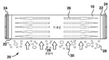
[0033] 도 1은 멤브레인 시트(10)를 도시한다. 멤브레인 시트(10)는 내부 채널들(14)을 제공하기 위해 형성되고 그리고 함께 결합된 2개의 기판 시트들(12)로 구성된다. 기판 시트들(12)의 외측들은 다공성 분리 층(16)으로 코팅된다. 분리 층(16)은 한외 여과(ultrafiltration) 또는 정밀 여과(microfiltration) 범위의 공극들을 가질 수 있다. 2개의 기판 시트들(12) 사이의 중앙 시트(18)는 선택적이지만, 보다 강성적인 멤브레인 시트(10)를 제공하기 위해 부가될 수 있다. 대안적으로, 멤브레인 시트(10)는 매끄러운 면형성된(faced) 평탄 시트 멤브레인일 수 있다. 매끄러운 면 평탄 시트 멤브레인은, 예를 들어, 내부 프레임 구성, 내부 투과물 스페이서 구성 또는 통합 투과물 채널 구성을 가질 수 있다. 멤브레인 시트(10)는 MF(microfiltration) 또는 UF(ultrafiltration) 범위의 공극들을 가질 수 있다.1 shows a
[0034] 도 2는 멤브레인 모듈(20)을 도시한다. 모듈(20)은 하나 이상의 멤브레인 시트들(10)을 갖는다. 내부 채널들(14)에 개방된 멤브레인 시트들(10)의 모서리들(즉, 도 1에 도시되는 모서리들)은 대안적으로, 대안적으로 포팅 헤드들 또는 투과물 수집기들로 불리는 헤더들(22)에서 포팅된다(potted). 사용시, 헤더들(22)은 일반적으로 수직으로 배향되며 그리고 내부 채널들(14)은 일반적으로 수평이다. 헤더들(22)의 투과물 포트들(24)에 적용되는 흡입은 투과물(26)이 내부 채널들(14)에서 생성되고 그리고 헤더들(22)을 통해 유동하는 것을 유발한다. 모듈(20)은 통상적으로 다수의 평행한 멤브레인 시트들(10)을 갖는다. 인접한 멤브레인 시트들(10)은 통상적으로, 일반적으로 동일한 폭의 수직 갭들에 의해 분리된다. 멤브레인 시트들(10) 사이에, 메쉬와 같은 시트 형상 공급 측 스페이서가 존재하지 않는다. 바람직하게는, 멤브레인 시트들(10) 사이에 수직 바들의 세트와 같은 간헐(intermittent) 스페이서가 또한 존재하지 않는다. 바람직하게는, 인접한 멤브레인 시트들(10) 사이의 갭들은 개방된다.2 shows the
[0035] MBR(Membrane Bioreactor)에서 사용될 때, 모듈(20)을 유지하는 개방 탱크는 통상적으로 활성된 슬러지 프로세스에 따라 혼합액(mixed liquor)으로 채워진다. 멤브레인 모듈(20) 및 탱크는 2차 정화기(clarifier)를 대체한다. 모듈(20) 아래로부터 제공되는 거품들(28)은, 혼합액(30)이 인접한 멤브레인 시트들(10) 사이의 갭들을 통하는 것을 포함하는 모듈(20)을 통해 위쪽으로 유동하는 것을 돕거나 유발한다.
When used in MBR (Membrane Bioreactor), the open tank holding the
[0036] 도 3은 모듈(20)을 통한 혼합액(30)(또는 다른 공급 액체)의 유동을 추가적으로 예시하기 위해 절취 개방된 모듈(20)의 개략도를 도시한다. 멤브레인 시트들(10)의 물결(undulating) 모양은, 혼합액이 상승함에 따라, 혼합액(30)에서 난류를 생성한다. 멤브레인 시트들(10)은 혼합액(30) 및 거품들(28)이 멤브레인 시트들 사이를 이동함에 따라 진동한다. 거품들(28)은 혼합액 유동을 보조하거나 유발하는 것 이외에도, 멤브레인 시트들(10)의 일부 직접 세척을 제공할 수 있다.3 shows a schematic view of the
[0037] 도 4는 3개의 모듈들(20)의 스택(32)을 도시한다. 모듈들(20)은 상하로 수직으로 적층된다. 하부 모듈의 투과물 포트들(24)은 상부 모듈의 헤더들(22)에서의 소켓들(보이지 않음)에 끼워맞춤한다. 가장 낮은 모듈(20)에서의 소켓들은 플러깅된다(plugged). 가장 높은 모듈의 투과 포트들(24)은 투과물 인출 파이프에 연결될 수 있고, 그리고 3개 모두의 모듈들(20)로부터 투과물을 인출하는데 사용될 수 있다. 스택들(32)은 또한, 2개, 4개 또는 다른 수의 모듈들(20)로 제조될 수 있다. 인접한 모듈들의 헤더들(22)이 수직으로 정렬되고 연속적이기 때문에, 공급 액체는 헤더들(22)에 의해 방해받지 않고 전체 스택(32)을 통해 수직으로 유동할 수 있다.4 shows a
[0038] 도 5는 프레임(42)에서 복수의 모듈들(20)을 보유하는 블록(40)을 도시한다. 모듈들(20)은 프레임(42)에 나란히 배치된다. 모듈(20)은 프레임(42) 안으로 또는 밖으로 수직으로 미끄러질 수 있다. 프레임(42)에 있을 때, 모듈(20)의 헤더들(22)은, 도시되는 예에서 프레임(42)에 부착된 플라스틱 몰딩들에 의해 제공되는 대응하는 슬롯들(44) 내이 끼워맞춤한다.5 shows a
[0039] 도 6은 수직으로 함께 상하로 적층되는 3개의 블록들(40)로 구성되는 카세트(50)를 도시한다. 선택적으로, 제조된 카세트(50)는 1개, 2개, 4개 또는 다른 수의 블록들(40)을 갖는다. 상부 블록(40)의 투과물 포트들(24)은 선택적으로 도시된 바와 같은 커넥터 파이프들(52)을 통해 투과물 헤더 파이프(54)에 연결된다. 블록들(40)의 프레임들(42)은 도시되는 예에서 그들의 단부들 상의 너트들을 갖는 나사결합식 로드들인 스트럿들(struts)(58)에 의해 서로 연결된다. 스트럿들(58)은 또한, 탱크에 카세트(50)를 걸기 위해 사용될 수 있는 카세트 프레임(56)에 상부 블록(40)을 부착한다. 공기 공급 파이프들(60)은, 카세트의 저부로의 공기가 가장 낮은 블록(40) 아래에서 폭기장치들(보이지 않음) 세트로 공급되게 한다.6 shows a
[0040] 도 7은 탱크(70)에 설치된 카세트(50)를 도시한다. 카세트 프레임들(56)은 탱크(70)의 벽들 상에서, 특히 도시된 예에서 탱크(70)에 부착된 레지들(ledges)(72) 상에 놓인다. 대안적으로, 카세트(50)는 탱크(70)의 저부에 놓일 수 있거나, 카세트(50)는 탱크(70)의 저부에 놓인 프레임 또는 다른 구조에 부착될 수 있다.7 shows a
[0041] 탱크(70)는 선택적으로 도시된 바와 같은 카세트(50)를 근접하게 둘러싼다. 혼합액(또는 다른 공급 액체)은 바람직하게는 탱크의 일단부로부터 탱크(70)의 저부의 채널(74)로 공급되고 그리고 탱크(70)의 반대편 단부의 최상부의 위어(weir)(도시되지 않음)로부터 나온다. 이러한 배열은 모듈들(20)을 통한 공급 액체의 평균 상향 유동을 제공한다. 다수의 카세트들(50)은 탱크(70)의 길이를 따라 이격될 수 있고 그리고 멤브레인 트레인을 제조하도록 조합될 수 있다. 완전한 멤브레인 시스템은 하나 이상의 트레인들을 가질 수 있다.The
[0042] 공기 공급 파이프들(60)은 카세트(50) 아래에서 수평으로 연장된다. 각각의 공기 공급 파이프(60)의 수평 부분은 일련의 홀들을 가지며, 하나의 홀은 1개 내지 5개의 모듈들(20)의 각각의 수직 스택 아래에 위치된다. 복수의 폭기장치들(도 7에서 보이지 않음)(바람직하게는, 하나의 폭기장치는 모듈들(20)의 각각의 수직 스택을 위한 것임)은 가장 낮은 블록(40)의 프레임(42)에 부착되고 그리고 공기 공급 파이프들(60)의 수평 부분들에 대해 수직하고 그리고 공기 공급 파이프들의 수평 부분들 위에 있는 카세트(50)의 저부에 걸쳐 연장한다. 폭기장치들은 폭기장치들 아래로 공기 공급 파이프들(60)에 연결된다. 카세트(50)에서의 모듈들(20)의 각각의 스택은 스택에서 가장 낮은 모듈(20) 아래에 하나의 폭기장치를 갖는다. 폭기장치는 천공된 고무 슬리브에 의해 덮인 길이를 따라 일련의 홀들을 갖는 파이프이다. 공기는 홀 밖으로 그리고 고무 슬리브 내로 유동한다. 공기의 압력은 고무 슬리브에서의 천공들을 강제하여, 미세 거품들이 방출되는 것을 유발한다. 고무 슬리브에서의 개구들은 1 내지 3mm 범위의 직경을 가지는 원의 면적을 가질 수 있다. 대안적으로, 폭기장치는 내부에 일련의 홀들을 갖는 파이프일 수 있다. 홀들은 직경이 5mm 미만, 예를 들어 2mm 내지 4.5mm의 직경을 갖는 원의 면적을 가질 수 있다.
[0043] 도 8은 모듈(20)에서 멤브레인 시트들(10)의 세트를 도시한다. 멤브레인 시트들(10)은 오목부들(8)을 갖는다. 멤브레인 시트들(10)은 폭 또는 두께(C)를 갖는다. 도시된 예에서, 두께(C)는, 대부분의 멤브레인 표면적을 덮는 규칙적인 표면 특징부들의 말단에서 측정된다. 매끄러운 측 평탄 시트 멤브레인은 시트(10) 전체에 걸쳐 일반적으로 일정한 폭 또는 두께(C)를 갖는다. 멤브레인 시트들(10)은 또한 중심 대 중심(center-to-center) 간격(B)을 갖는다.8 shows a set of
[0044] 멤브레인 시트들(10)은 면 대 면 간격(A)을 갖는다. 달리 언급되지 않는 한, 본원에서 간격, 또는 이격되어 있는 멤브레인 시트들 또는 다른 유사한 언급들에 대한 임의의 참조는 면 대 면 간격을 지칭한다. 간격(A)은 중심 대 중심 간격(B)에서 폭(C)을 뺀 것과 동일하다. 도 8에 도시된 바와 같이, 인접한 시트들(10)은 예를 들어, 시트(10)에서 인접한 오목부들(8) 사이의 수직 거리의 절반만큼 수직으로 서로 오프셋되는 오목부들(8)과 배열될 수 있다. 멤브레인 시트들은, 예를 들어, 4mm 이하, 3mm 이하 또는 2mm 이하의 간격(A)으로 서로 근접하게 이격된다.The
예들Examples
[0045] 멤브레인 시트들 사이에 1.5mm의 간격을 갖는 본원에 설명되는 모듈(20)과 유사한 주름진 평탄 시트 모듈은 0.005 및 0.01 scfm(standard cubic feet per minute)의 공기 유량들에서, 굵은 거품 폭기장치 및 미세 거품 폭기장치로 작동되었다. 굵은 거품 폭기장치는 4mm보다 더 큰 거품들을 생성했다. 용어 "굵은"은 모듈 간격에 대해 이러한 예에서 사용되고 그리고 용어의 통상적으로 업계 사용에 따라 사용되지 않는다. 굵은 거품 폭기장치는 3mm보다 더 작은 거품들을 생성했다. 거품 크기는 모듈(20)의 저부 아래, 특히 폭기장치 최상부와 폭기장치의 최상부로부터 5cm 위 사이의 공간에서 측정되었다. 멤브레인들의 내부 상의 흡입은 다양한 플럭스 값들을 생성하도록 변경되었다. 투과성은 다른 플럭스 값들에서 측정되었다.[0045] A corrugated flat sheet module similar to the
[0046] 도 9는 둘 모두의 폭기장치들로 획득된 통상적인 결과들을 도시한다. 멤브레인의 투과성은 미세 거품 폭기장치로, 특히 보다 높은 플럭스에서 보다 높았다. 결과들은 또한, 심지어 낮은 공기 유량에서도 멤브레인이 미세 거품 폭기장치와 함께 잘 작동하는 것을 도시한다. 미세 거품 폭기장치가 플럭스에 관계없이, 0.005 또는 0.01 scfm의 공기로 작동했을 때, 멤브레인 투과성은 본질적으로 동일했다. 0.005 scfm의 공기로 작동하는 미세 거품 폭기장치와의 멤브레인 투과성은 통상적으로 0.01 scfm의 공기로 작동하는 굵은 거품 폭기장치와의 동일한 플럭스에서 멤브레인 투과성과 동일하거나 이보다 더 양호하여, 미세 거품 폭기장치로의 상당한 에너지 절약을 제안했다.9 shows typical results obtained with both aerators. The permeability of the membrane was higher with the microbubble aerator, especially at higher fluxes. The results also show that the membrane works well with the microbubble aerator even at low air flow rates. When the microbubble aerator was operated with 0.005 or 0.01 scfm of air, regardless of the flux, the membrane permeability was essentially the same. Membrane permeability with microbubble aerators operating with 0.005 scfm air is typically equal to or better than membrane permeability at the same flux as coarse foam aerators operating with 0.01 scfm air, so Proposed significant energy savings.
[0047] 동일한 모듈로의 부가의 검사들은 4개 크기들(평균 직경으로, 1mm 미만; 1.5mm; 2mm 초과; 5mm 초과)의 거품들로 수행되었다. FiberPlate 모듈은 1.5mm의 시트 간격을 갖는다. 모듈은 다양한 플럭스 값들에서 작동되었으며, 그리고 투과성이 측정되었다. 도 10에서 표시된 바와 같이, 약 2mm 이하(즉, 1mm 내지 2mm)의 크기를 갖는 거품은 5mm 거품들보다 상당히 더 양호하게 실시되었다. 1.5mm 크기의 거품들은 약 2mm 크기를 갖는 거품들보다 더 일관되게 양호하게 실시되었다.Additional tests with the same modulus were performed with bubbles of four sizes (average diameter, less than 1 mm; 1.5 mm; more than 2 mm; more than 5 mm). The FiberPlate module has a sheet spacing of 1.5mm. The module was run at various flux values, and the permeability was measured. As indicated in FIG. 10, bubbles having a size of about 2 mm or less (ie, 1 mm to 2 mm) performed significantly better than 5 mm bubbles. Bubbles with a size of 1.5 mm performed more consistently than bubbles with a size of about 2 mm.
[0048] 추가 테스트들은 1.5mm, 2.2mm 및 3.8mm의 면 대 면 간격들로 구성되는 3개의 유사한 모듈들로 수행되었다. 모듈들은 0.006 scfm/ft2의 멤브레인 표면적에서 제공되는 공기로, 멤브레인 바이오리액터에서 RAS(return activated sludge)의 4Q 재순환에 가까운 재순환 유동을 갖는 탱크에서 3.7g/L의 벤토나이트 현탁액(bentonite suspension)에서 작동되었다. 거품들은 멤브레인들의 저부의 약 150mm 아래에 위치되는 디퓨저들로부터 제공되었다. 하나의 디퓨저는 2mm의 공칭(즉, 동등한 원 직경) 개구 크기를 갖는 고무 슬리브 유형 미세 거품 디퓨저였다. 다른 디퓨저는 4mm 직경의 홀을 갖는다.Further tests were performed with three similar modules consisting of face-to-face spacings of 1.5mm, 2.2mm and 3.8mm. The modules operate in a 3.7 g/L bentonite suspension in a tank with a recirculation flow close to 4Q recirculation of return activated sludge (RAS) in a membrane bioreactor with air provided at a membrane surface area of 0.006 scfm/ft 2 Became. The bubbles were provided from diffusers located about 150 mm below the bottom of the membranes. One diffuser was a rubber sleeve type fine foam diffuser with a nominal (ie equivalent circle diameter) opening size of 2 mm. Other diffusers have 4mm diameter holes.
[0049] 표 1은 면 대 면 간격 및 거품 크기의 상이한 조합들로 18GFD의 플럭스에서 작동하는 동안 TMP 증가(psi/분)를 도시한다. 표 1의 결과들은, 면 대 면 간격의 1배 내지 2배의 크기를 가지는 거품들의 경우에, 특히 3mm 이하의 매우 근접한 면 대 면 간격의 경우, 양호한 결과들이 획득된다는 것을 암시한다.Table 1 shows the TMP increase (psi/min) while operating at a flux of 18 GFD with different combinations of face to face spacing and foam size. The results in Table 1 imply that good results are obtained in the case of bubbles having a size of 1 to 2 times the face-to-face spacing, especially in the case of very close face-to-face spacing of 3 mm or less.

[0050] 본원에서의 상세한 설명 및 예들은 주름진 평탄 시트 모듈에 기초하지만, 유사한 결과들이 매끄러운 측 평탄 시트 모듈들로 달성될 것으로 예상된다. 임의의 특정 프로세스 조건 또는 특정한 예에서의 물리적 치수가 특정한 예에서 양방향으로 약 50% 만큼 변할 수 있는 것이 또한 예상된다.[0050] Although the detailed description and examples herein are based on a corrugated flat sheet module, similar results are expected to be achieved with smooth side flat sheet modules. It is also contemplated that any particular process condition or physical dimension in a particular example may vary by about 50% in both directions in a particular example.
[0051] 국제 공보 번호 WO 2011/130853 및 미국 공보 번호 제2017095773호는 본원에 인용에 의해 포함된다.International Publication No. WO 2011/130853 and US Publication No. 2017095773 are incorporated herein by reference.
Claims (14)
평탄 시트 멤브레인들(flat sheet membranes)의 모듈(module) ─ 상기 평탄 시트 멤브레인들은 4mm 이하의 멤브레인들 사이의 면 대 면 간격(face-to-face spacing)을 가짐 ─ ; 및,
상기 멤브레인들 아래에 있는 미세 거품 폭기장치(fine bubble aerator)를 포함하며, 상기 미세 거품 폭기장치는 4mm 이하, 3mm 이하, 또는 상기 멤브레인들 사이의 간격보다 100%이하 또는 50% 초과 만큼 더 큰 크기를 가지는 거품들을 생성하도록 구성되는,
침지식 멤브레인 여과 유닛.As an immersed membrane filtration unit,
Module of flat sheet membranes—the flat sheet membranes have a face-to-face spacing between the membranes of no more than 4 mm—; And,
A fine bubble aerator under the membranes, wherein the fine bubble aerator is 4 mm or less, 3 mm or less, or 100% or less or 50% larger than the spacing between the membranes. Configured to create bubbles having
Submerged Membrane Filtration Unit.
상기 미세 거품 폭기장치는 2mm 이하 또는 상기 멤브레인들 사이의 면 대 면 간격 이하의 크기를 가지는 거품들을 생성하도록 구성되는,
침지식 멤브레인 여과 유닛.The method of claim 1,
The microbubble aerator is configured to generate bubbles having a size of 2 mm or less or a face-to-face spacing between the membranes,
Submerged Membrane Filtration Unit.
상기 멤브레인들 사이의 상기 면 대 면 간격은 3mm 이하, 2mm 이하 또는 1.5mm 이하인,
침지식 멤브레인 여과 유닛.The method of claim 1 or 2,
The face-to-face spacing between the membranes is 3 mm or less, 2 mm or less, or 1.5 mm or less,
Submerged Membrane Filtration Unit.
상기 멤브레인들 사이의 상기 면 대 면 간격은 3mm 이하, 예를 들어, 약 2.2mm이며, 그리고 상기 미세 거품 폭기장치는 직경이 5mm 이하, 예를 들어 약 4mm의 개구들을 가지는,
침지식 멤브레인 여과 유닛.The method of claim 1,
The face-to-face spacing between the membranes is 3 mm or less, e.g., about 2.2 mm, and the microbubble aerator has openings of 5 mm or less, e.g. about 4 mm in diameter,
Submerged Membrane Filtration Unit.
상기 멤브레인들 사이의 상기 면 대 면 간격은 2mm 이하, 예를 들어, 약 1.5mm이며, 그리고 상기 미세 거품 폭기장치는 직경이 3mm 이하, 예를 들어 약 2mm의 개구들을 가지는,
침지식 멤브레인 여과 유닛.The method of claim 1,
The face-to-face spacing between the membranes is 2 mm or less, e.g., about 1.5 mm, and the microbubble aerator has openings of 3 mm or less, e.g. about 2 mm in diameter,
Submerged Membrane Filtration Unit.
상기 멤브레인들은 주름진(corrugated) 면들을 가지는,
침지식 멤브레인 여과 유닛.The method according to any one of claims 1 to 5,
The membranes have corrugated sides,
Submerged Membrane Filtration Unit.
인접한 멤브레인들의 주름부들은 상이한 높이들에 있는,
침지식 멤브레인 여과 유닛.The method of claim 6,
The corrugations of adjacent membranes are at different heights,
Submerged Membrane Filtration Unit.
상기 프로세스는,
평탄 시트 멤브레인들의 모듈을 물에 침지하는 단계 ─ 상기 모듈은 4mm 이하의 멤브레인들 사이의 간격을 가짐 ─ ; 및,
상기 멤브레인들 아래에 거품들을 생성하는 단계를 포함하며, 상기 거품들은 5mm 이하, 또는 3mm 이하, 또는 상기 멤브레인들 사이의 간격보다 100%이하 또는 50% 초과만큼 더 큰 크기를 가지는,
물을 여과하는 프로세스.As a process of filtering water,
The process,
Immersing a module of flat sheet membranes in water—the module has a gap between the membranes of no more than 4 mm—; And,
Creating bubbles under the membranes, wherein the bubbles have a size of 5 mm or less, or 3 mm or less, or 100% or less or greater than 50% of the spacing between the membranes,
The process of filtering water.
상기 거품들은 2mm 이하, 또는 상기 멤브레인들 사이의 간격 이하의 크기를 가지는,
물을 여과하는 프로세스.The method of claim 8,
The bubbles have a size of less than 2 mm, or less than the spacing between the membranes,
The process of filtering water.
상기 멤브레인들 사이의 상기 간격은 3mm 이하, 2mm 이하 또는 1.5mm 이하인,
물을 여과하는 프로세스.The method according to claim 8 or 9,
The spacing between the membranes is 3 mm or less, 2 mm or less, or 1.5 mm or less,
The process of filtering water.
상기 멤브레인들 사이의 상기 면 대 면 간격은 3mm 이하, 예를 들어, 약 2.2mm이며, 그리고 상기 미세 거품 폭기장치는 직경이 5mm 이하, 예를 들어 약 4mm의 개구들을 가지는,
물을 여과하는 프로세스.The method of claim 8,
The face-to-face spacing between the membranes is 3 mm or less, e.g., about 2.2 mm, and the microbubble aerator has openings of 5 mm or less, e.g. about 4 mm in diameter,
The process of filtering water.
상기 멤브레인들 사이의 상기 면 대 면 간격은 2 mm 이하, 예를 들어, 약 1.5mm이며, 그리고 상기 미세 거품 폭기장치는 직경이 3 mm 이하, 예를 들어 약 2mm의 개구들을 가지는,
물을 여과하는 프로세스.The method of claim 8,
The face-to-face spacing between the membranes is 2 mm or less, e.g., about 1.5 mm, and the microbubble aerator has openings of 3 mm or less in diameter, e.g. about 2 mm,
The process of filtering water.
상기 멤브레인들은 주름진 면들을 가지는,
물을 여과하는 프로세스.The method according to any one of claims 8 to 12,
The membranes have corrugated sides,
The process of filtering water.
인접한 멤브레인들의 주름부들은 상이한 높이들에 있는,
물을 여과하는 프로세스.The method of claim 13,
The corrugations of adjacent membranes are at different heights,
The process of filtering water.
Applications Claiming Priority (3)
| Application Number | Priority Date | Filing Date | Title |
|---|---|---|---|
| US201862693617P | 2018-07-03 | 2018-07-03 | |
| US62/693,617 | 2018-07-03 | ||
| PCT/CA2019/050910 WO2020006628A1 (en) | 2018-07-03 | 2019-07-02 | Tightly spaced flat sheet immersed membranes and fine bubble aeration |
Publications (1)
| Publication Number | Publication Date |
|---|---|
| KR20210044772A true KR20210044772A (en) | 2021-04-23 |
Family
ID=69060678
Family Applications (1)
| Application Number | Title | Priority Date | Filing Date |
|---|---|---|---|
| KR1020217003259A KR20210044772A (en) | 2018-07-03 | 2019-07-02 | Closely spaced flat sheet submerged membranes and fine foam aeration |
Country Status (9)
| Country | Link |
|---|---|
| US (1) | US20210220776A1 (en) |
| EP (1) | EP3817845A4 (en) |
| JP (2) | JP2021529087A (en) |
| KR (1) | KR20210044772A (en) |
| CN (1) | CN112823051A (en) |
| AU (1) | AU2019298254A1 (en) |
| CA (1) | CA3104749A1 (en) |
| IL (1) | IL279899A (en) |
| WO (1) | WO2020006628A1 (en) |
Families Citing this family (4)
| Publication number | Priority date | Publication date | Assignee | Title |
|---|---|---|---|---|
| CN111439842A (en) * | 2020-05-27 | 2020-07-24 | 天津碧水源膜材料有限公司 | Longitudinal vibration's MBR corrugated membrane device |
| IL301792A (en) * | 2020-10-05 | 2023-05-01 | Fibracast Ltd | Operation of immersed membrane using cross flow |
| EP4223395A1 (en) * | 2022-02-07 | 2023-08-09 | Mann+Hummel Life Sciences & Environment Holding Singapore Pte. Ltd. | Filter module, membrane bioreactor and use of the filter module |
| CN116177722B (en) * | 2023-01-10 | 2023-07-21 | 重庆大学 | Coupling system and method for in-situ ecological elimination of endogenous pollution of water body |
Family Cites Families (19)
| Publication number | Priority date | Publication date | Assignee | Title |
|---|---|---|---|---|
| US5651888A (en) | 1992-12-16 | 1997-07-29 | Kubota Corporation | Filtration membrane cartridge |
| TW255835B (en) | 1994-01-07 | 1995-09-01 | Kubota Kk | Filtration membrane module |
| JP3539753B2 (en) * | 1994-04-04 | 2004-07-07 | 株式会社クボタ | Membrane separation unit |
| TW283657B (en) * | 1995-03-31 | 1996-08-21 | Mitsui Eng & Shipbuilding Co | Membrane device and its processing device |
| US5772831A (en) | 1995-04-03 | 1998-06-30 | Kubota Corporation | Filter membrane element and method of manufacturing same |
| JP3778758B2 (en) | 2000-02-04 | 2006-05-24 | 株式会社クボタ | Manufacturing method of submerged membrane cartridge |
| CA2398461C (en) | 2000-12-04 | 2007-10-30 | Kubota Corporation | Multistage immersion type membrane separator and high-concentration wastewater treatment facility using same |
| EP1625885A1 (en) | 2004-08-11 | 2006-02-15 | Vlaamse Instelling Voor Technologisch Onderzoek (Vito) | Integrated permeate channel membrane |
| DE102005046675A1 (en) | 2005-09-29 | 2007-04-05 | Microdyn-Nadir Gmbh | Filter element useful for micro-, ultra- or nanofiltration of liquids or gases comprises filter membrane deposited on drainage element |
| JPWO2008038436A1 (en) * | 2006-09-25 | 2010-01-28 | 東レ株式会社 | Membrane separation method, submerged membrane separation apparatus, and membrane separation process |
| EP2125630A4 (en) * | 2007-02-14 | 2011-10-05 | Dxv Water Technologies Llc | Depth exposed membrane for water extraction |
| WO2008139836A1 (en) * | 2007-05-10 | 2008-11-20 | Toray Industries, Inc. | Immersion type membrane separation apparatus and method of operating the same |
| CN101293701B (en) * | 2008-05-27 | 2011-06-22 | 大连理工大学 | Trapezia flat-plate membrane component for strengthening pollution resistant function of aeration in membrane bioreactor |
| WO2011130853A1 (en) | 2010-04-20 | 2011-10-27 | Fibracast Ltd. | Formed sheet membrane element and filtration system |
| WO2012098130A1 (en) | 2011-01-17 | 2012-07-26 | Vds Weaving Nv | A tridimensional woven fabric, an integrated permeate channel membrane comprising said fabric and uses thereof |
| WO2017049408A1 (en) * | 2015-09-24 | 2017-03-30 | Fibracast Ltd. | Method of operating membrane filter |
| JP2017080688A (en) * | 2015-10-29 | 2017-05-18 | 東レ株式会社 | Separation membrane element and separation membrane module |
| EP3424587A4 (en) * | 2016-02-29 | 2019-10-23 | Toray Industries, Inc. | Flat-sheet separation membrane element, element unit, flat-sheet separation membrane module, and operation method for flat-sheet separation membrane module |
| CN107174960A (en) * | 2017-05-04 | 2017-09-19 | 同济大学 | A kind of method that utilization nano bubble is aerated decelerating membrane pollution |
-
2019
- 2019-07-02 JP JP2020573490A patent/JP2021529087A/en active Pending
- 2019-07-02 CN CN201980051143.6A patent/CN112823051A/en active Pending
- 2019-07-02 EP EP19830672.2A patent/EP3817845A4/en active Pending
- 2019-07-02 WO PCT/CA2019/050910 patent/WO2020006628A1/en active Application Filing
- 2019-07-02 KR KR1020217003259A patent/KR20210044772A/en not_active Application Discontinuation
- 2019-07-02 CA CA3104749A patent/CA3104749A1/en active Pending
- 2019-07-02 US US17/255,534 patent/US20210220776A1/en active Pending
- 2019-07-02 AU AU2019298254A patent/AU2019298254A1/en active Pending
-
2020
- 2020-12-31 IL IL279899A patent/IL279899A/en unknown
-
2023
- 2023-11-20 JP JP2023196728A patent/JP2024025787A/en active Pending
Also Published As
| Publication number | Publication date |
|---|---|
| EP3817845A1 (en) | 2021-05-12 |
| AU2019298254A1 (en) | 2021-01-21 |
| JP2021529087A (en) | 2021-10-28 |
| JP2024025787A (en) | 2024-02-26 |
| EP3817845A4 (en) | 2022-03-30 |
| IL279899A (en) | 2021-03-01 |
| US20210220776A1 (en) | 2021-07-22 |
| CA3104749A1 (en) | 2020-01-09 |
| WO2020006628A1 (en) | 2020-01-09 |
| CN112823051A (en) | 2021-05-18 |
Similar Documents
| Publication | Publication Date | Title |
|---|---|---|
| KR20210044772A (en) | Closely spaced flat sheet submerged membranes and fine foam aeration | |
| KR100500339B1 (en) | Apparatus and Method for Treating Water | |
| US7972510B2 (en) | Filtration apparatus | |
| CN113244774A (en) | Membrane module system using membrane bundle enclosure and pulsed aeration and method of operation | |
| JP5308028B2 (en) | Cleaning method for air diffuser | |
| JP5472312B2 (en) | Membrane module, membrane unit and membrane separator | |
| JP2010247086A (en) | Flat membrane module and water treatment apparatus using the same | |
| JP5238128B2 (en) | Solid-liquid separation device for solid-liquid mixed processing liquid | |
| JP5094022B2 (en) | Aeration device and membrane filtration unit applied when collecting filtrate of solid-liquid mixed processing liquid | |
| JP2007209949A (en) | Filtrate recovery device of solid-liquid mixed/processed liquid | |
| KR100500488B1 (en) | Immersion Type Flat Membrane Module | |
| JP2003112017A (en) | Filtration membrane module and clean water producing method | |
| EP2905065B1 (en) | Aerator device and filter system including the same | |
| KR200285695Y1 (en) | Immersion Type Flat Membrane Module | |
| JP3937620B2 (en) | Membrane separation device and water separation method | |
| JP3979114B2 (en) | Filtration membrane module and fresh water generation method | |
| KR20220034869A (en) | Systems and methods for transporting submerged membrane units | |
| JP2001321645A (en) | Filter membrane element and method for manufacturing permeated water | |
| JP2007268415A (en) | Immersion type membrane separation apparatus and water producing method | |
| JP2003175319A (en) | Membrane element, membrane module, water making apparatus and water making method | |
| GB2421199A (en) | Submerged membrane filtration module | |
| JP2001321766A (en) | Method of manufacturing filtration membrane element and permeate | |
| KR101515685B1 (en) | Membrane module comprising section divider for reducing membrane fouling | |
| JP2002126464A (en) | Filter membrane element and method fo producing permeated water | |
| JPH0857269A (en) | Membrane separator |
Legal Events
| Date | Code | Title | Description |
|---|---|---|---|
| A201 | Request for examination | ||
| E902 | Notification of reason for refusal | ||
| E601 | Decision to refuse application |