KR20210038910A - Intraluminal device with wire braiding configuration - Google Patents
Intraluminal device with wire braiding configuration Download PDFInfo
- Publication number
- KR20210038910A KR20210038910A KR1020217005431A KR20217005431A KR20210038910A KR 20210038910 A KR20210038910 A KR 20210038910A KR 1020217005431 A KR1020217005431 A KR 1020217005431A KR 20217005431 A KR20217005431 A KR 20217005431A KR 20210038910 A KR20210038910 A KR 20210038910A
- Authority
- KR
- South Korea
- Prior art keywords
- wires
- wire
- region
- intraluminal device
- cable
- Prior art date
Links
Images


Classifications
-
- A—HUMAN NECESSITIES
- A61—MEDICAL OR VETERINARY SCIENCE; HYGIENE
- A61B—DIAGNOSIS; SURGERY; IDENTIFICATION
- A61B17/00—Surgical instruments, devices or methods, e.g. tourniquets
- A61B17/22—Implements for squeezing-off ulcers or the like on the inside of inner organs of the body; Implements for scraping-out cavities of body organs, e.g. bones; Calculus removers; Calculus smashing apparatus; Apparatus for removing obstructions in blood vessels, not otherwise provided for
- A61B17/221—Gripping devices in the form of loops or baskets for gripping calculi or similar types of obstructions
-
- A—HUMAN NECESSITIES
- A61—MEDICAL OR VETERINARY SCIENCE; HYGIENE
- A61F—FILTERS IMPLANTABLE INTO BLOOD VESSELS; PROSTHESES; DEVICES PROVIDING PATENCY TO, OR PREVENTING COLLAPSING OF, TUBULAR STRUCTURES OF THE BODY, e.g. STENTS; ORTHOPAEDIC, NURSING OR CONTRACEPTIVE DEVICES; FOMENTATION; TREATMENT OR PROTECTION OF EYES OR EARS; BANDAGES, DRESSINGS OR ABSORBENT PADS; FIRST-AID KITS
- A61F2/00—Filters implantable into blood vessels; Prostheses, i.e. artificial substitutes or replacements for parts of the body; Appliances for connecting them with the body; Devices providing patency to, or preventing collapsing of, tubular structures of the body, e.g. stents
- A61F2/01—Filters implantable into blood vessels
- A61F2/0108—Both ends closed, i.e. legs gathered at both ends
-
- A—HUMAN NECESSITIES
- A61—MEDICAL OR VETERINARY SCIENCE; HYGIENE
- A61B—DIAGNOSIS; SURGERY; IDENTIFICATION
- A61B17/00—Surgical instruments, devices or methods, e.g. tourniquets
- A61B2017/00526—Methods of manufacturing
-
- A—HUMAN NECESSITIES
- A61—MEDICAL OR VETERINARY SCIENCE; HYGIENE
- A61B—DIAGNOSIS; SURGERY; IDENTIFICATION
- A61B17/00—Surgical instruments, devices or methods, e.g. tourniquets
- A61B2017/00831—Material properties
- A61B2017/00902—Material properties transparent or translucent
- A61B2017/00915—Material properties transparent or translucent for radioactive radiation
- A61B2017/0092—Material properties transparent or translucent for radioactive radiation for X-rays
-
- A—HUMAN NECESSITIES
- A61—MEDICAL OR VETERINARY SCIENCE; HYGIENE
- A61B—DIAGNOSIS; SURGERY; IDENTIFICATION
- A61B17/00—Surgical instruments, devices or methods, e.g. tourniquets
- A61B17/22—Implements for squeezing-off ulcers or the like on the inside of inner organs of the body; Implements for scraping-out cavities of body organs, e.g. bones; Calculus removers; Calculus smashing apparatus; Apparatus for removing obstructions in blood vessels, not otherwise provided for
- A61B17/221—Gripping devices in the form of loops or baskets for gripping calculi or similar types of obstructions
- A61B2017/2212—Gripping devices in the form of loops or baskets for gripping calculi or similar types of obstructions having a closed distal end, e.g. a loop
-
- A—HUMAN NECESSITIES
- A61—MEDICAL OR VETERINARY SCIENCE; HYGIENE
- A61F—FILTERS IMPLANTABLE INTO BLOOD VESSELS; PROSTHESES; DEVICES PROVIDING PATENCY TO, OR PREVENTING COLLAPSING OF, TUBULAR STRUCTURES OF THE BODY, e.g. STENTS; ORTHOPAEDIC, NURSING OR CONTRACEPTIVE DEVICES; FOMENTATION; TREATMENT OR PROTECTION OF EYES OR EARS; BANDAGES, DRESSINGS OR ABSORBENT PADS; FIRST-AID KITS
- A61F2/00—Filters implantable into blood vessels; Prostheses, i.e. artificial substitutes or replacements for parts of the body; Appliances for connecting them with the body; Devices providing patency to, or preventing collapsing of, tubular structures of the body, e.g. stents
- A61F2/01—Filters implantable into blood vessels
- A61F2002/016—Filters implantable into blood vessels made from wire-like elements
-
- A—HUMAN NECESSITIES
- A61—MEDICAL OR VETERINARY SCIENCE; HYGIENE
- A61F—FILTERS IMPLANTABLE INTO BLOOD VESSELS; PROSTHESES; DEVICES PROVIDING PATENCY TO, OR PREVENTING COLLAPSING OF, TUBULAR STRUCTURES OF THE BODY, e.g. STENTS; ORTHOPAEDIC, NURSING OR CONTRACEPTIVE DEVICES; FOMENTATION; TREATMENT OR PROTECTION OF EYES OR EARS; BANDAGES, DRESSINGS OR ABSORBENT PADS; FIRST-AID KITS
- A61F2250/00—Special features of prostheses classified in groups A61F2/00 - A61F2/26 or A61F2/82 or A61F9/00 or A61F11/00 or subgroups thereof
- A61F2250/0058—Additional features; Implant or prostheses properties not otherwise provided for
- A61F2250/0096—Markers and sensors for detecting a position or changes of a position of an implant, e.g. RF sensors, ultrasound markers
- A61F2250/0098—Markers and sensors for detecting a position or changes of a position of an implant, e.g. RF sensors, ultrasound markers radio-opaque, e.g. radio-opaque markers
Abstract
관강내 장치 및 관강내 장치를 제조하는 방법이 제공될 수 있다. 일 구현예에서, 관강내 장치는 복수의 와이어로 형성될 수 있고, 원위 코일, 근위 코일, 및 원위 코일과 근위 코일 사이에 위치된 확장 가능한 메쉬 세그먼트를 포함할 수도 있다. 원위 코일, 근위 코일 및 확장 가능한 메쉬 세그먼트는 하나의 단일 구조로 형성될 수 있으며, 복수의 와이어 중 적어도 하나의 와이어는 근위 코일로부터 원위 코일까지 연속적으로 연장된다. 다른 구현예에서, 관강내 장치는 장치의 원위 팁을 형성하는 원위 코일을 포함할 수도 있다. 원위 코일은 부드럽고 비외상성이도록 구성될 수도 있다. 다른 구현예에서, 관강내 장치는 와이어 교차부에서 만나는 두 쌍의 와이어를 포함할 수도 있다. 와이어 교차부에서, 각 와이어 쌍의 하나의 와이어는 다른 와이어 쌍의 와이어들 사이를 통과할 수도 있다. 다른 구현예에서, 관강내 장치는 복수의 와이어로 형성될 수 있고, 원위 코일, 근위 코일, 및 원위 코일과 근위 코일 사이에 위치된 확장 가능한 메쉬 세그먼트를 포함할 수도 있다. 근위 코일은 복수의 와이어 중에서 원위 코일 및 확장 가능한 메쉬 세그먼트보다 더 많은 와이어를 포함할 수도 있다.An intraluminal device and a method of manufacturing an intraluminal device may be provided. In one embodiment, the intraluminal device may be formed of a plurality of wires and may include a distal coil, a proximal coil, and an expandable mesh segment positioned between the distal and proximal coils. The distal coil, the proximal coil and the expandable mesh segment may be formed into one single structure, and at least one of the plurality of wires extends continuously from the proximal coil to the distal coil. In other embodiments, the intraluminal device may include a distal coil forming the distal tip of the device. The distal coil may be configured to be smooth and non-traumatic. In other embodiments, the intraluminal device may include two pairs of wires meeting at wire crossings. At wire crossings, one wire of each wire pair may pass between wires of another wire pair. In other embodiments, the intraluminal device may be formed of a plurality of wires and may include a distal coil, a proximal coil, and an expandable mesh segment positioned between the distal coil and the proximal coil. The proximal coil may include more wires than the distal coil and expandable mesh segment among the plurality of wires.

Description
관련 출원에 대한 상호 참조Cross-reference to related applications
본 출원은 2018년 7월 26일에 출원된 미국 가출원 번호 제 62/703,795 호의 우선권을 주장하며, 그 개시 내용은 그 전체가 참조에 의해 본 명세서에 포함된다.This application claims priority to U.S. Provisional Application No. 62/703,795, filed July 26, 2018, the disclosure of which is incorporated herein by reference in its entirety.
본 개시는 응괴(clot)와 같은 폐색물을 인간의 혈관으로부터 회수하도록 구성된 혈관내(intravascular) 및 관강내(intraluminal) 의료 장치 및 시스템에 관한 것이다. 본 개시는 또한 혈관내 및 관강내 의료 장치 및 시스템을 제조하는 방법에 관한 것이다.The present disclosure relates to intravascular and intraluminal medical devices and systems configured to recover an obstruction such as a clot from a human blood vessel. The present disclosure also relates to methods of making intravascular and intraluminal medical devices and systems.
혈관내 및 관강내 의료 장치는 일반적으로 혈관과 같은 중공의 신체 기관 내의 다양한 의학적 상태를 치료하는 데 사용된다. 예컨대, 수축된 신체 혈관을 확장하거나 손상 또는 폐색된 신체 내강(lumen)에 대한 지지를 제공하기 위해, 팽창 가능한 또는 확장 가능한 장치가 활용될 수 있다. 혈관내 및 관강내 장치는 또한 신체 내강으로부터 응괴나 결석과 같은 폐색물을 포착하고 제거하는 데에도 활용할 수 있다. 예컨대, 와이어 메쉬(wire mesh) 장치는 폐색부를 관통 및/또는 포착하기 위해 혈관 내 폐색부 내에서 확장될 수 있다.Intravascular and intraluminal medical devices are generally used to treat a variety of medical conditions within hollow body organs such as blood vessels. For example, an expandable or expandable device may be utilized to expand constricted bodily blood vessels or to provide support for an injured or occluded body lumen. Intravascular and intraluminal devices can also be used to capture and remove obstructions such as clots or stones from the body's lumen. For example, a wire mesh device may be expanded within an intravascular obstruction to penetrate and/or capture the obstruction.
두개내 혈관계와 같은 일부 혈관계에는 좁으면서도 구불구불한 혈관이 포함된다. 두개내 혈관계에 폐색 또는 협착이 발생하면, 혈관내 치료 장치가 구불구불한 해부학적 구조를 통과하여 치료 부위에 도달할 수 있다. 이들 치료 장치는 좁은 혈관에 적합할 만큼 충분히 작은 직경을 가져야 하지만, 치료 부위에서 원하는 작업을 수행할 수 있을 만큼 충분히 견고해야 할 뿐만 아니라, 최소한의 합병증으로 치료 부위까지 조종될 수 있을 만큼 충분히 유연해야 한다. 합병증에는 무엇보다도 구불구불한 경로를 통해 치료 부위까지 장치를 전달함에 있어서의 어려움뿐만 아니라, 너무 단단한 두개내 및 관강내 장치로 인한 건강한 혈관 벽의 손상 가능성이 포함될 수 있다.Some vascular systems, such as the intracranial vascular system, contain narrow and serpentine blood vessels. When occlusion or narrowing of the intracranial vascular system occurs, the intravascular treatment device can pass through a serpentine anatomical structure to reach the treatment site. These treatment devices must have a diameter small enough to fit into narrow vessels, but not only must be sturdy enough to perform the desired operation at the treatment site, but also must be flexible enough to be manipulated to the treatment site with minimal complications. do. Complications may include, among other things, difficulty in delivering the device to the treatment site via a serpentine route, as well as the possibility of damage to the walls of healthy blood vessels due to too tight intracranial and intraluminal devices.
본 개시는 원격 신체 부위에서의 혈관 확장 또는 응괴 포착(clot capture)과 같은 치료 작업을 수행하기에 충분한 강성을 작동 부분에서 나타내지만, 장치가 치료 부위로 전달될 때 잠재적인 합병증을 피하기에 충분히 유연한 원위 팁(distal tip)을 나타내는 개선된 장치 및 시스템에 관한 것이다.The present disclosure demonstrates in the working part sufficient stiffness to perform a therapeutic task such as vasodilation or clot capture at a remote body site, but flexible enough to avoid potential complications when the device is delivered to the treatment site. It relates to an improved device and system that exhibits a distal tip.
본 명세서에는 원격 신체 부위에서 치료 작업을 수행하기에 충분한 작동 부분에서의 강성을 갖지만, 또한 그러한 장치를 신체에 삽입하는 것으로 인한 잠재적인 합병증을 피하기에 충분히 유연한 원위 팁을 나타내는 관강내 장치가 개시된다. 또한 이러한 관강내 장치를 제조하는 방법이 여기에 개시된다.Disclosed herein is an intraluminal device that exhibits a distal tip that has sufficient stiffness in the working part to perform a therapeutic operation at a remote body part, but is also flexible enough to avoid potential complications from inserting such a device into the body. . Also disclosed herein is a method of manufacturing such an intraluminal device.
본 개시의 일 실시예에 따르면, 복수의 와이어로 형성된 세장형 몸체를 포함하는 관강내 장치가 제공된다. 관강내 장치는 복수의 와이어가 제 1 케이블을 형성하도록 꼬여 있는 제 1 영역을 포함한다. 관강내 장치는 또한 제 1 영역에 대해 원위에 있는 제 2 영역을 포함하는데, 제 2 영역에서 복수의 와이어는 혈액 응괴(blood clot)를 포착하도록 구성된 확장 가능한 메쉬 세그먼트(expandable mesh segment)를 형성하도록 직조된다. 관강내 장치는 또한 제 2 영역에 대해 원위에 있으며 세장형 몸체의 원위 팁을 형성하는 제 3 영역을 포함하며, 제 3 영역에서의 복수의 와이어는 제 2 케이블을 형성하도록 꼬여 있다. 복수의 와이어 중 적어도 하나의 와이어는 제 1 영역으로부터 세장형 몸체의 원위 팁까지 연속적으로 연장된다.According to an embodiment of the present disclosure, an intraluminal device including an elongated body formed of a plurality of wires is provided. The intraluminal device includes a first region in which a plurality of wires are twisted to form a first cable. The intraluminal device also includes a second region distal to the first region, wherein the plurality of wires form an expandable mesh segment configured to capture blood clots. Is woven. The intraluminal device also includes a third region distal to the second region and forming a distal tip of the elongate body, wherein a plurality of wires in the third region are twisted to form a second cable. At least one of the plurality of wires extends continuously from the first region to the distal tip of the elongate body.
확장 가능한 메쉬 세그먼트는 복수의 와이어가 제 1 직조 패턴(weave pattern)을 형성하도록 직조되는 적어도 하나의 확장 가능한 필터 세그먼트를 포함하고, 제 1 직조 패턴은 2개 이상의 와이어 사이에 형성된 개구를 내부에 갖는다. 확장 가능한 메쉬 세그먼트는 또한 복수의 와이어가 제 2 직조 패턴을 형성하도록 직조되는 적어도 하나의 확장 가능한 응괴 포착 구역을 포함하고, 제 2 직조 패턴은 제 1 직조 패턴과 상이하며, 2개 이상의 와이어 사이에 형성된 개구를 내부에 갖는다. 확장된 구성에서, 적어도 하나의 응괴 포착 구역의 개구는 적어도 하나의 필터 세그먼트의 개구보다 더 크다. 적어도 하나의 응괴 포착 구역에서의 복수의 와이어는 적어도 하나의 응괴 포착 구역 내의 복수의 와이어 그룹으로 그룹화되는데, 복수의 와이어 그룹의 각 와이어 그룹은 적어도 2개의 와이어를 포함하고, 서로 얽힌 와이어 조합(intertwined wire combination)을 형성한다. 적어도 하나의 응괴 포착 구역의 개구는 서로 얽힌 와이어 조합들 중에서 적어도 2개 사이에 형성된다. 복수의 와이어 그룹의 각 와이어 그룹은 1개의 와이어, 2개의 와이어, 3개의 와이어 또는 4개의 와이어를 포함한다. 적어도 하나의 확장 가능한 필터 세그먼트는 적어도 하나의 확장 가능한 응괴 포착 구역보다 더 작은 응괴를 포착하도록 구성된다. 확장 가능한 메쉬 세그먼트는 제 1 필터 세그먼트, 제 1 필터 세그먼트에 대해 원위에 있는 제 2 필터 세그먼트, 제 1 필터 세그먼트와 관강내 장치의 제 1 영역 사이에 위치되는 제 1 응괴 포착 구역, 및 제 2 필터 세그먼트와 관강내 장치의 제 3 영역 사이에 위치되는 제 2 응괴 포착 구역을 포함한다. 복수의 와이어는 8개 와이어의 세트, 10개 와이어의 세트 및 12개 와이어의 세트 중 적어도 하나를 포함한다. 적어도 하나의 와이어는 40 마이크론 내지 200 마이크론의 직경을 갖는다. 예컨대, 적어도 하나의 와이어는 40 마이크론, 45 마이크론, 50 마이크론, 55 마이크론, 60 마이크론, 65 마이크론, 70 마이크론, 75 마이크론, 80 마이크론, 85 마이크론, 90 마이크론, 95 마이크론, 100 마이크론, 105 마이크론, 110 마이크론, 115 마이크론, 120 마이크론, 125 마이크론, 130 마이크론, 135 마이크론, 140 마이크론, 145 마이크론, 150 마이크론, 155 마이크론, 160 마이크론, 165 마이크론, 170 마이크론, 175 마이크론, 180 마이크론, 185 마이크론, 190 마이크론, 195 마이크론 및 200 마이크론, 또는 이들의 범위 중 적어도 하나인 직경을 가질 수 있다. 예컨대, 적어도 하나의 와이어는 50 마이크론 내지 75 마이크론 범위의 직경을 가질 수 있다. 관강내 장치는 또한 세장형 몸체를 따르는 지점에 위치된 적어도 하나의 방사선 불투과성 마커(radiopaque marker)를 포함하고, 세장형 몸체를 따르는 지점은 제 2 영역에 대해 원위에 있는 지점 및 제 2 영역의 근위에 있는 지점 중 적어도 하나이다. 관강내 장치의 제 1 영역, 관강내 장치의 제 2 영역 및 관강내 장치의 제 3 영역은 하나의 단일 구조로 형성된다.The expandable mesh segment comprises at least one expandable filter segment in which a plurality of wires are woven to form a first weave pattern, the first woven pattern having an opening formed therein between the two or more wires. . The expandable mesh segment also includes at least one expandable clot trapping zone in which the plurality of wires are woven to form a second woven pattern, the second woven pattern being different from the first woven pattern, and between two or more wires. It has an opening formed therein. In the expanded configuration, the opening of the at least one clot trapping zone is larger than the opening of the at least one filter segment. The plurality of wires in the at least one clot trapping zone are grouped into a plurality of wire groups in the at least one clot trapping zone, wherein each wire group of the plurality of wire groups includes at least two wires, and intertwined wires are intertwined. wire combination). The opening of the at least one clot trapping zone is formed between at least two of the wire combinations entangled with each other. Each wire group of the plurality of wire groups includes one wire, two wires, three wires, or four wires. The at least one expandable filter segment is configured to capture smaller clots than the at least one expandable clot capture zone. The expandable mesh segment comprises a first filter segment, a second filter segment distal to the first filter segment, a first agglomeration trapping zone positioned between the first filter segment and the first region of the intraluminal device, and a second filter. And a second clot capture zone located between the segment and the third area of the intraluminal device. The plurality of wires includes at least one of a set of 8 wires, a set of 10 wires, and a set of 12 wires. At least one wire has a diameter of 40 microns to 200 microns. For example, at least one wire is 40 microns, 45 microns, 50 microns, 55 microns, 60 microns, 65 microns, 70 microns, 75 microns, 80 microns, 85 microns, 90 microns, 95 microns, 100 microns, 105 microns, 110 Micron, 115 micron, 120 micron, 125 micron, 130 micron, 135 micron, 140 micron, 145 micron, 150 micron, 155 micron, 160 micron, 165 micron, 170 micron, 175 micron, 180 micron, 185 micron, 190 micron, It may have a diameter that is at least one of 195 microns and 200 microns, or a range thereof. For example, at least one wire can have a diameter in the range of 50 microns to 75 microns. The intraluminal device also includes at least one radiopaque marker located at a point along the elongate body, the point along the elongate body being a point distal to the second area and of the second area. It is at least one of the proximal points. The first area of the intraluminal device, the second area of the intraluminal device and the third area of the intraluminal device are formed into one single structure.
본 개시의 다른 실시예에 따르면, 복수의 와이어로 형성된 세장형 몸체를 포함하는 관강내 장치를 제조하는 방법이 제공된다. 이 방법은 세장형 몸체의 제 1 케이블을 형성하기 위해 맨드릴(mandrel)의 제 1 세그먼트 상에서 복수의 와이어를 꼬는 것을 포함한다. 이 방법은 또한 혈액 응괴를 포착하도록 구성된 세장형 몸체의 확장 가능한 메쉬 세그먼트를 형성하기 위해 맨드릴의 제 2 세그먼트 상에서 복수의 와이어를 직조하는 것을 포함한다. 이 방법은 또한 세장형 몸체의 제 2 케이블을 형성하기 위해 맨드릴의 제 3 세그먼트 상에서 복수의 와이어를 꼬는 것을 포함한다. 맨드릴의 제 2 세그먼트는 맨드릴의 제 1 세그먼트와 맨드릴의 제 3 세그먼트 사이에 위치된다.According to another embodiment of the present disclosure, a method of manufacturing an intraluminal device including an elongated body formed of a plurality of wires is provided. The method involves twisting a plurality of wires on a first segment of a mandrel to form a first cable of an elongate body. The method also includes weaving a plurality of wires on the second segment of the mandrel to form an expandable mesh segment of an elongate body configured to capture blood clots. The method also includes twisting a plurality of wires on the third segment of the mandrel to form a second cable of the elongate body. The second segment of the mandrel is positioned between the first segment of the mandrel and the third segment of the mandrel.
본 방법은 또한 확장 가능한 메쉬 세그먼트를 열처리하는 것을 포함한다. 맨드릴의 제 2 세그먼트는 맨드릴의 제 1 세그먼트 및 맨드릴의 제 3 세그먼트보다 직경이 더 크다. 복수의 와이어는 8개 와이어의 세트, 10개 와이어의 세트 및 12개 와이어의 세트 중 적어도 하나를 포함한다. 복수의 와이어 중 적어도 하나의 와이어는 40 마이크론 내지 200 마이크론의 직경을 갖는다. 예컨대, 적어도 하나의 와이어는 40 마이크론, 45 마이크론, 50 마이크론, 55 마이크론, 60 마이크론, 65 마이크론, 70 마이크론, 75 마이크론, 80 마이크론, 85 마이크론, 90 마이크론, 95 마이크론, 100 마이크론, 105 마이크론, 110 마이크론, 115 마이크론, 120 마이크론, 125 마이크론, 130 마이크론, 135 마이크론, 140 마이크론, 145 마이크론, 150 마이크론, 155 마이크론, 160 마이크론, 165 마이크론, 170 마이크론, 175 마이크론, 180 마이크론, 185 마이크론, 190 마이크론, 195 마이크론 및 200 마이크론 또는 이들의 범위 중 적어도 하나인 직경을 가질 수 있다. 예컨대, 복수의 와이어 중 적어도 하나의 와이어는 50 마이크론 내지 75 마이크론 범위의 직경을 가질 수 있다. 세장형 몸체의 제 1 케이블, 세장형 몸체의 확장 가능한 메쉬 세그먼트 및 세장형 몸체의 제 2 케이블은 하나의 단일 구조로 형성된다.The method also includes heat treating the expandable mesh segment. The second segment of the mandrel is larger in diameter than the first segment of the mandrel and the third segment of the mandrel. The plurality of wires includes at least one of a set of 8 wires, a set of 10 wires, and a set of 12 wires. At least one of the plurality of wires has a diameter of 40 microns to 200 microns. For example, at least one wire is 40 microns, 45 microns, 50 microns, 55 microns, 60 microns, 65 microns, 70 microns, 75 microns, 80 microns, 85 microns, 90 microns, 95 microns, 100 microns, 105 microns, 110 Micron, 115 micron, 120 micron, 125 micron, 130 micron, 135 micron, 140 micron, 145 micron, 150 micron, 155 micron, 160 micron, 165 micron, 170 micron, 175 micron, 180 micron, 185 micron, 190 micron, It may have a diameter that is at least one of 195 microns and 200 microns or a range thereof. For example, at least one of the plurality of wires may have a diameter ranging from 50 microns to 75 microns. The first cable of the elongate body, the expandable mesh segment of the elongate body and the second cable of the elongate body are formed into one single structure.
본 개시의 추가 실시예에 따르면, 복수의 와이어로 형성된 세장형 몸체를 포함하는 관강내 장치가 제공된다. 관강내 장치는 복수의 와이어가 제 1 케이블을 형성하도록 꼬여 있는 제 1 영역을 포함한다. 관강내 장치는 또한 제 1 영역에 대해 원위에 있는 제 2 영역을 포함하는데, 제 2 영역에서 복수의 와이어는 혈액 응괴를 포착하도록 구성된 확장 가능한 메쉬 세그먼트를 형성하도록 직조된다. 관강내 장치는 또한 제 2 영역에 대해 원위에 있으며 세장형 몸체의 원위 팁을 형성하는 제 3 영역을 포함하며, 제 3 영역에서의 복수의 와이어는 제 2 케이블을 형성하도록 꼬여 있다. 제 2 케이블은 제 1 케이블보다 더 유연하도록 구성된다.According to a further embodiment of the present disclosure, an intraluminal device comprising an elongated body formed of a plurality of wires is provided. The intraluminal device includes a first region in which a plurality of wires are twisted to form a first cable. The intraluminal device also includes a second region distal to the first region, in which a plurality of wires are woven to form an expandable mesh segment configured to capture blood clots. The intraluminal device also includes a third region distal to the second region and forming a distal tip of the elongate body, wherein a plurality of wires in the third region are twisted to form a second cable. The second cable is configured to be more flexible than the first cable.
복수의 와이어 중 적어도 하나의 와이어는 40 마이크론 내지 200 마이크론의 직경을 갖는다. 예컨대, 적어도 하나의 와이어는 40 마이크론, 45 마이크론, 50 마이크론, 55 마이크론, 60 마이크론, 65 마이크론, 70 마이크론, 75 마이크론, 80 마이크론, 85 마이크론, 90 마이크론, 95 마이크론, 100 마이크론, 105 마이크론, 110 마이크론, 115 마이크론, 120 마이크론, 125 마이크론, 130 마이크론, 135 마이크론, 140 마이크론, 145 마이크론, 150 마이크론, 155 마이크론, 160 마이크론, 165 마이크론, 170 마이크론, 175 마이크론, 180 마이크론, 185 마이크론, 190 마이크론, 195 마이크론 및 200 마이크론, 또는 이들의 범위 중 적어도 하나인 직경을 가질 수 있다. 예컨대, 복수의 와이어 중 적어도 하나의 와이어는 50 마이크론 내지 75 마이크론 범위의 직경을 가질 수 있다. 제 2 케이블은 제 1 케이블보다 작은 케이블 권취 각도(cable coiling angle)를 갖도록 구성된다. 제 2 케이블에는 제 1 케이블보다 적은 수의 와이어가 있다. 제 2 케이블은 내부에 있는 복수의 와이어의 부분의 직경을 감소시키도록 처리된다.At least one of the plurality of wires has a diameter of 40 microns to 200 microns. For example, at least one wire is 40 microns, 45 microns, 50 microns, 55 microns, 60 microns, 65 microns, 70 microns, 75 microns, 80 microns, 85 microns, 90 microns, 95 microns, 100 microns, 105 microns, 110 Micron, 115 micron, 120 micron, 125 micron, 130 micron, 135 micron, 140 micron, 145 micron, 150 micron, 155 micron, 160 micron, 165 micron, 170 micron, 175 micron, 180 micron, 185 micron, 190 micron, It may have a diameter that is at least one of 195 microns and 200 microns, or a range thereof. For example, at least one of the plurality of wires may have a diameter ranging from 50 microns to 75 microns. The second cable is configured to have a smaller cable coiling angle than the first cable. The second cable has fewer wires than the first cable. The second cable is treated to reduce the diameter of a portion of the plurality of wires therein.
본 개시의 또 다른 실시예에 따르면, 복수의 와이어로 형성된 세장형 몸체를 포함하는 관강내 장치가 제공된다. 관강내 장치는 복수의 와이어가 제 1 케이블을 형성하도록 꼬여 있는 제 1 영역을 포함한다. 관강내 장치는 또한 제 1 영역에 대해 원위에 있는 제 2 영역을 포함하며, 제 2 영역에서 복수의 와이어는 확장 가능한 메쉬 세그먼트를 형성하도록 직조된다. 관강내 장치는 또한 제 2 영역에 대해 원위에 있으며 세장형 몸체의 원위 팁을 형성하는 제 3 영역을 포함하며, 제 3 영역에서의 복수의 와이어는 제 2 케이블을 형성하도록 꼬여 있다. 확장 가능한 메쉬 세그먼트에서의 복수의 와이어는 확장 가능한 메쉬 세그먼트 내의 복수의 와이어 쌍으로 그룹화되고, 복수의 와이어 쌍의 각 와이어 쌍은 서로 얽힌 와이어 조합을 형성한다. 복수의 와이어 쌍 중 적어도 제 1 와이어 쌍 및 복수의 와이어 쌍 중 적어도 제 2 와이어 쌍은 확장 가능한 메쉬 세그먼트에서 교차부를 형성하고, 제 1 와이어 쌍의 적어도 하나의 와이어는 교차부에서 제 2 와이어 쌍의 각 와이어 사이를 통과한다.According to another embodiment of the present disclosure, there is provided an intraluminal device including an elongated body formed of a plurality of wires. The intraluminal device includes a first region in which a plurality of wires are twisted to form a first cable. The intraluminal device also includes a second region distal to the first region, in which the plurality of wires are woven to form an expandable mesh segment. The intraluminal device also includes a third region distal to the second region and forming a distal tip of the elongate body, wherein a plurality of wires in the third region are twisted to form a second cable. The plurality of wires in the expandable mesh segment are grouped into a plurality of wire pairs in the expandable mesh segment, and each wire pair of the plurality of wire pairs forms a wire combination entangled with each other. At least a first wire pair of the plurality of wire pairs and at least a second wire pair of the plurality of wire pairs form an intersection in the expandable mesh segment, and at least one wire of the first wire pair is formed of the second wire pair at the intersection. It passes between each wire.
복수의 와이어 쌍 중 제 1 와이어 쌍은 교차부의 근위에 적어도 제 1 쌍 꼬임(pairwise twist)을 포함하고, 교차부의 원위에 적어도 제 2 쌍 꼬임을 포함한다. 제 2 와이어 쌍의 적어도 하나의 와이어는 교차부에서 제 1 와이어 쌍의 각 와이어 사이를 통과한다. 제 1 와이어 쌍의 적어도 하나의 와이어는 교차부에서 제 2 와이어 쌍의 와이어들 사이를 통과하지 않는다. 제 2 와이어 쌍의 적어도 하나의 와이어는 교차부에서 제 1 와이어 쌍의 와이어들 사이를 통과하지 않는다.The first wire pair of the plurality of wire pairs includes at least a first pairwise twist proximal to the intersection and at least a second pair twist distal to the intersection. At least one wire of the second wire pair passes between each wire of the first wire pair at the intersection. At least one wire of the first wire pair does not pass between the wires of the second wire pair at the intersection. At least one wire of the second wire pair does not pass between the wires of the first wire pair at the intersection.
본 개시의 다른 실시예에 따르면, 복수의 와이어로 형성된 세장형 몸체를 포함하는 관강내 장치가 제공된다. 관강내 장치는 복수의 와이어가 제 1 케이블을 형성하도록 꼬여 있는 제 1 영역을 포함한다. 관강내 장치는 또한 제 1 영역에 대해 원위에 있는 제 2 영역을 포함하며, 제 2 영역에서 복수의 와이어는 혈액 응괴를 포착하도록 구성된 확장 가능한 메쉬 세그먼트를 형성하도록 직조된다. 관강내 장치는 또한 제 2 영역에 대해 원위에 있으며 세장형 몸체의 원위 팁을 형성하는 제 3 영역을 포함하며, 제 3 영역에서의 복수의 와이어는 제 2 케이블을 형성하도록 꼬여 있다. 제 1 영역은 제 2 영역 및 제 3 영역 중 하나 이상보다 많은 와이어를 포함한다.According to another embodiment of the present disclosure, an intraluminal device including an elongated body formed of a plurality of wires is provided. The intraluminal device includes a first region in which a plurality of wires are twisted to form a first cable. The intraluminal device also includes a second region distal to the first region, in which the plurality of wires are woven to form an expandable mesh segment configured to capture blood clots. The intraluminal device also includes a third region distal to the second region and forming a distal tip of the elongate body, wherein a plurality of wires in the third region are twisted to form a second cable. The first region includes more wires than at least one of the second region and the third region.
제 2 영역은 제 3 영역과 동일한 수의 와이어를 포함한다. 제 2 영역은 제 3 영역보다 더 많은 와이어를 포함한다. 제 1 영역은 11개의 와이어를 포함하고, 제 2 영역은 8개의 와이어를 포함하고, 제 3 영역은 8개의 와이어를 포함한다. 제 1 영역은 12개의 와이어를 포함하고, 제 2 영역은 8개의 와이어를 포함하고, 제 3 영역은 8개의 와이어를 포함한다. 복수의 와이어 중 적어도 하나의 와이어는 제 1 영역으로부터 제 3 영역까지 연속적으로 연장된다. 관강내 장치의 제 1 영역, 관강내 장치의 제 2 영역 및 관강내 장치의 제 3 영역은 하나의 단일 구조로 형성된다.The second region includes the same number of wires as the third region. The second region contains more wires than the third region. The first area includes 11 wires, the second area includes 8 wires, and the third area includes 8 wires. The first area includes 12 wires, the second area includes 8 wires, and the third area includes 8 wires. At least one of the plurality of wires extends continuously from the first region to the third region. The first area of the intraluminal device, the second area of the intraluminal device and the third area of the intraluminal device are formed into one single structure.
본 개시의 추가 실시예에 따르면, 복수의 와이어로 형성된 세장형 몸체를 포함하는 관강내 장치를 제조하는 방법이 제공된다. 이 방법은 세장형 몸체의 제 1 케이블을 형성하기 위해 맨드릴의 제 1 세그먼트 상에서 복수의 와이어를 꼬는 것을 포함한다. 이 방법은 또한 제 1 케이블의 원위 단부에서 복수의 와이어 중 적어도 하나의 와이어를 절단하는 것을 포함한다. 이 방법은 또한 혈액 응괴를 포착하도록 구성된 세장형 몸체의 확장 가능한 메쉬 세그먼트를 형성하기 위해 맨드릴의 제 2 세그먼트 상에서 복수의 와이어의 나머지 와이어를 직조하는 것을 포함한다. 이 방법은 또한 세장형 몸체의 제 2 케이블을 형성하기 위해 맨드릴의 제 3 세그먼트 상에서 복수의 와이어의 나머지 와이어를 꼬는 것을 포함한다. 맨드릴의 제 2 세그먼트는 맨드릴의 제 1 세그먼트와 맨드릴의 제 3 세그먼트 사이에 위치된다.According to a further embodiment of the present disclosure, a method of manufacturing an intraluminal device comprising an elongate body formed of a plurality of wires is provided. The method includes twisting a plurality of wires on a first segment of a mandrel to form a first cable of an elongate body. The method also includes cutting at least one of the plurality of wires at the distal end of the first cable. The method also includes weaving the remaining wires of the plurality of wires on the second segment of the mandrel to form an expandable mesh segment of an elongate body configured to capture blood clots. The method also includes twisting the remaining wires of the plurality of wires on the third segment of the mandrel to form a second cable of the elongate body. The second segment of the mandrel is positioned between the first segment of the mandrel and the third segment of the mandrel.
이 방법은 또한 확장 가능한 메쉬 세그먼트의 원위 단부에서 복수의 와이어 중 적어도 하나의 와이어를 절단하는 것을 포함한다. 이 방법은 또한 확장 가능한 메쉬 세그먼트를 열처리하는 것을 포함한다. 맨드릴의 제 2 세그먼트는 맨드릴의 제 1 세그먼트 및 맨드릴의 제 3 세그먼트보다 직경이 더 크다. 복수의 와이어는 8개의 와이어, 10개의 와이어 또는 12개의 와이어를 포함한다. 복수의 와이어 중 적어도 하나의 와이어는 40 마이크론 내지 200 마이크론의 직경을 갖는다. 예컨대, 적어도 하나의 와이어는 40 마이크론, 45 마이크론, 50 마이크론, 55 마이크론, 60 마이크론, 65 마이크론, 70 마이크론, 75 마이크론, 80 마이크론, 85 마이크론, 90 마이크론, 95 마이크론, 100 마이크론, 105 마이크론, 110 마이크론, 115 마이크론, 120 마이크론, 125 마이크론, 130 마이크론, 135 마이크론, 140 마이크론, 145 마이크론, 150 마이크론, 155 마이크론, 160 마이크론, 165 마이크론, 170 마이크론, 175 마이크론, 180 마이크론, 185 마이크론, 190 마이크론, 195 마이크론 및 200 마이크론, 또는 이들의 범위 중 적어도 하나인 직경을 가질 수 있다. 예컨대, 복수의 와이어 중 적어도 하나의 와이어는 50 마이크론 내지 75 마이크론 범위의 직경을 가질 수 있다. 세장형 몸체의 제 1 케이블, 세장형 몸체의 확장 가능한 메쉬 세그먼트, 및 세장형 몸체의 제 2 케이블은 하나의 단일 구조로 형성된다.The method also includes cutting at least one of the plurality of wires at the distal end of the expandable mesh segment. The method also includes heat-treating the expandable mesh segment. The second segment of the mandrel is larger in diameter than the first segment of the mandrel and the third segment of the mandrel. The plurality of wires includes 8 wires, 10 wires or 12 wires. At least one of the plurality of wires has a diameter of 40 microns to 200 microns. For example, at least one wire is 40 microns, 45 microns, 50 microns, 55 microns, 60 microns, 65 microns, 70 microns, 75 microns, 80 microns, 85 microns, 90 microns, 95 microns, 100 microns, 105 microns, 110 Micron, 115 micron, 120 micron, 125 micron, 130 micron, 135 micron, 140 micron, 145 micron, 150 micron, 155 micron, 160 micron, 165 micron, 170 micron, 175 micron, 180 micron, 185 micron, 190 micron, It may have a diameter that is at least one of 195 microns and 200 microns, or a range thereof. For example, at least one of the plurality of wires may have a diameter ranging from 50 microns to 75 microns. The first cable of the elongate body, the expandable mesh segment of the elongate body, and the second cable of the elongate body are formed into one single structure.
본 개시의 추가 실시예에 따르면, 복수의 와이어로 형성된 세장형 몸체를 포함하는 관강내 장치가 제공된다. 관강내 장치는 복수의 와이어가 제 1 케이블을 형성하도록 꼬여 있는 제 1 영역; 복수의 와이어가 확장 가능한 메쉬 세그먼트를 형성하도록 직조되어 있는, 제 1 영역에 대해 원위에 있는 제 2 영역; 및 제 2 영역에 대해 원위에 있으며 세장형 몸체의 원위 팁을 형성하는 제 3 영역을 포함하고, 제 3 영역에서의 복수의 와이어는 제 2 케이블을 형성하도록 꼬여 있다. 확장 가능한 메쉬 세그먼트에서의 복수의 와이어는 제 1 와이어 그룹 및 제 2 와이어 그룹을 포함한다. 제 1 와이어 그룹은 2개의 와이어를 포함하고, 제 2 와이어 그룹은 3개의 와이어를 포함한다. 복수의 와이어의 각각의 와이어는 제 1 측면 및 제 1 측면의 반대편의 제 2 측면을 포함한다. 제 1 와이어 그룹의 제 1 와이어는 제 2 와이어 그룹의 제 1 와이어 및 제 2 와이어 그룹의 제 2 와이어 둘 모두의 제 1 측면과 교차하도록 구성된다. 제 1 와이어 그룹의 제 1 와이어는 제 2 와이어 그룹의 제 3 와이어의 제 2 측면과 교차하도록 구성된다. 제 1 와이어 그룹의 제 2 와이어는 제 2 와이어 그룹의 제 1 와이어 및 제 2 와이어 그룹의 제 2 와이어 둘 모두의 제 2 측면과 교차하도록 구성된다. 제 1 와이어 그룹의 제 2 와이어는 제 2 와이어 그룹의 제 3 와이어의 제 1 측면과 교차하도록 구성된다.According to a further embodiment of the present disclosure, an intraluminal device comprising an elongated body formed of a plurality of wires is provided. The intraluminal device comprises: a first region in which a plurality of wires are twisted to form a first cable; A second region distal to the first region, wherein the plurality of wires are woven to form an expandable mesh segment; And a third region distal to the second region and forming a distal tip of the elongate body, wherein the plurality of wires in the third region are twisted to form a second cable. The plurality of wires in the expandable mesh segment includes a first wire group and a second wire group. The first wire group includes two wires, and the second wire group includes three wires. Each wire of the plurality of wires includes a first side and a second side opposite the first side. The first wire of the first wire group is configured to intersect a first side of both the first wire of the second wire group and the second wire of the second wire group. The first wire of the first wire group is configured to intersect the second side of the third wire of the second wire group. The second wire of the first wire group is configured to intersect the second side of both the first wire of the second wire group and the second wire of the second wire group. The second wire of the first wire group is configured to intersect the first side of the third wire of the second wire group.
본 개시의 추가 실시예에 따르면, 복수의 와이어로 형성된 세장형 몸체를 포함하는 관강내 장치가 제공된다. 관강내 장치는 복수의 와이어가 제 1 케이블을 형성하도록 꼬여 있는 제 1 영역; 복수의 와이어가 확장 가능한 메쉬 세그먼트를 형성하도록 직조되어 있는, 제 1 영역에 대해 원위에 있는 제 2 영역; 및 제 2 영역에 대해 원위에 있으며 세장형 몸체의 원위 팁을 형성하는 제 3 영역을 포함하고, 제 3 영역에서의 복수의 와이어는 제 2 케이블을 형성하도록 꼬여 있다. 확장 가능한 메쉬 세그먼트에서의 복수의 와이어는 제 1 와이어 그룹 및 제 2 와이어 그룹을 포함한다. 제 1 와이어 그룹은 2개의 와이어를 포함한다. 제 2 와이어 그룹은 3개의 와이어를 포함한다. 복수의 와이어의 각각의 와이어는 제 1 측면 및 제 1 측면의 반대편의 제 2 측면을 포함한다. 제 1 와이어 그룹의 제 1 와이어는 제 2 와이어 그룹의 제 1 와이어의 제 1 측면과 교차하고 제 2 와이어 그룹의 제 2 와이어 및 제 2 와이어 그룹의 제 3 와이어 둘 모두의 제 2 측면과 교차하도록 구성된다. 제 1 와이어 그룹의 제 2 와이어는 제 2 와이어 그룹에서의 각 와이어의 제 1 측면과 교차하도록 구성된다.According to a further embodiment of the present disclosure, an intraluminal device comprising an elongated body formed of a plurality of wires is provided. The intraluminal device comprises: a first region in which a plurality of wires are twisted to form a first cable; A second region distal to the first region, wherein the plurality of wires are woven to form an expandable mesh segment; And a third region distal to the second region and forming a distal tip of the elongate body, wherein the plurality of wires in the third region are twisted to form a second cable. The plurality of wires in the expandable mesh segment includes a first wire group and a second wire group. The first wire group includes two wires. The second wire group includes three wires. Each wire of the plurality of wires includes a first side and a second side opposite the first side. The first wire of the first wire group intersects the first side of the first wire of the second wire group and intersects the second side of both the second wire of the second wire group and the third wire of the second wire group. It is composed. The second wire of the first wire group is configured to intersect the first side of each wire in the second wire group.
본 개시의 추가 실시예에 따르면, 복수의 와이어로 형성된 세장형 몸체를 포함하는 관강내 장치가 제공된다. 관강내 장치는 복수의 와이어가 제 1 케이블을 형성하도록 꼬여 있는 제 1 영역; 복수의 와이어가 확장 가능한 메쉬 세그먼트를 형성하도록 직조되어 있는, 제 1 영역에 대해 원위에 있는 제 2 영역; 및 제 2 영역에 대해 원위에 있으며 세장형 몸체의 원위 팁을 형성하는 제 3 영역을 포함하고, 제 3 영역에서의 복수의 와이어는 제 2 케이블을 형성하도록 꼬여 있다. 확장 가능한 메쉬 세그먼트에서의 복수의 와이어는 제 1 와이어 그룹 및 제 2 와이어 그룹을 포함한다. 제 1 와이어 그룹은 3개의 와이어를 포함하고 제 2 와이어 그룹은 3개의 와이어를 포함한다. 복수의 와이어의 각각의 와이어는 제 1 측면 및 제 1 측면의 반대편의 제 2 측면을 포함한다. 제 1 와이어 그룹의 제 1 와이어는 제 2 와이어 그룹의 제 1 와이어의 제 1 측면과 교차하고 제 2 와이어 그룹의 제 2 와이어 및 제 2 와이어 그룹의 제 3 와이어 둘 모두의 제 2 측면과 교차하도록 구성된다. 제 1 와이어 그룹의 제 2 와이어는 제 2 와이어 그룹의 제 1 와이어의 제 1 측면과 교차하고 제 2 와이어 그룹의 제 2 와이어 및 제 2 와이어 그룹의 제 3 와이어 둘 모두의 제 2 측면과 교차하도록 구성된다. 제 1 와이어 그룹의 제 3 와이어는 제 2 와이어 그룹의 각 와이어의 제 1 측면과 교차하도록 구성된다.According to a further embodiment of the present disclosure, an intraluminal device comprising an elongated body formed of a plurality of wires is provided. The intraluminal device comprises: a first region in which a plurality of wires are twisted to form a first cable; A second region distal to the first region, wherein the plurality of wires are woven to form an expandable mesh segment; And a third region distal to the second region and forming a distal tip of the elongate body, wherein the plurality of wires in the third region are twisted to form a second cable. The plurality of wires in the expandable mesh segment includes a first wire group and a second wire group. The first wire group includes 3 wires and the second wire group includes 3 wires. Each wire of the plurality of wires includes a first side and a second side opposite the first side. The first wire of the first wire group intersects the first side of the first wire of the second wire group and intersects the second side of both the second wire of the second wire group and the third wire of the second wire group. It is composed. The second wire of the first wire group intersects the first side of the first wire of the second wire group and crosses the second side of both the second wire of the second wire group and the third wire of the second wire group. It is composed. The third wire of the first wire group is configured to intersect the first side of each wire of the second wire group.
본 개시의 추가 실시예에 따르면, 복수의 와이어로 형성된 세장형 몸체를 포함하는 관강내 장치가 제공된다. 관강내 장치는 복수의 와이어가 제 1 케이블을 형성하도록 꼬여 있는 제 1 영역; 복수의 와이어가 확장 가능한 메쉬 세그먼트를 형성하도록 직조되어 있는, 제 1 영역에 대해 원위에 있는 제 2 영역; 및 제 2 영역에 대해 원위에 있으며 세장형 몸체의 원위 팁을 형성하는 제 3 영역을 포함하고, 제 3 영역에서의 복수의 와이어는 제 2 케이블을 형성하도록 꼬여 있다. 확장 가능한 메쉬 세그먼트에서의 복수의 와이어는 확장 가능한 메쉬 세그먼트 내의 복수의 와이어 그룹으로 그룹화된다. 복수의 와이어 그룹의 각각의 와이어 그룹은 확장 가능한 메쉬 세그먼트에서 복수의 와이어 그룹의 다른 와이어 그룹과 교차부를 형성한다. 복수의 와이어 그룹 중 제 1 와이어 그룹은 3개의 와이어 각각이 3개의 와이어 중 다른 2개의 와이어를 감싸는 꼬임 구조(twisting structure)를 형성하는 3개의 와이어를 포함한다. 제 1 와이어 그룹의 꼬임 구조는 제 1 와이어 그룹의 인접한 두 교차부 사이의 확장 가능한 메쉬 세그먼트의 부분 내에 위치된다.According to a further embodiment of the present disclosure, an intraluminal device comprising an elongated body formed of a plurality of wires is provided. The intraluminal device comprises: a first region in which a plurality of wires are twisted to form a first cable; A second region distal to the first region, wherein the plurality of wires are woven to form an expandable mesh segment; And a third region distal to the second region and forming a distal tip of the elongate body, wherein the plurality of wires in the third region are twisted to form a second cable. The plurality of wires in the expandable mesh segment are grouped into a plurality of wire groups within the expandable mesh segment. Each wire group of the plurality of wire groups forms an intersection with other wire groups of the plurality of wire groups in the expandable mesh segment. The first wire group of the plurality of wire groups includes three wires each forming a twisting structure in which each of the three wires surrounds the other two wires of the three wires. The twist structure of the first wire group is located within a portion of the expandable mesh segment between two adjacent intersections of the first wire group.
본 개시의 추가 실시예에 따르면, 복수의 와이어로 형성된 세장형 몸체를 포함하는 관강내 장치가 제공된다. 관강내 장치는 복수의 와이어가 제 1 케이블을 형성하도록 꼬여 있는 제 1 영역; 복수의 와이어가 확장 가능한 메쉬 세그먼트를 형성하도록 직조되어 있는, 제 1 영역에 대해 원위에 있는 제 2 영역; 및 제 2 영역에 대해 원위에 있으며 세장형 몸체의 원위 팁을 형성하는 제 3 영역을 포함하고, 제 3 영역에서의 복수의 와이어는 제 2 케이블을 형성하도록 꼬여 있다. 확장 가능한 메쉬 세그먼트에서의 복수의 와이어는 확장 가능한 메쉬 세그먼트 내의 복수의 와이어 그룹으로 그룹화된다. 복수의 와이어 그룹의 각각의 와이어 그룹은 확장 가능한 메쉬 세그먼트에서 복수의 와이어 그룹의 다른 와이어 그룹과 교차부를 형성한다. 복수의 와이어 그룹 중 제 1 와이어 그룹은 3개의 와이어를 포함한다. 3개의 와이어 중 제 1 와이어와 3개의 와이어 중 제 2 와이어는 제 1 및 제 2 와이어 각각이 서로를 감싸는 꼬임 구조를 형성한다. 3개의 와이어 중 제 3 와이어는 꼬임 구조에서 제 1 와이어 및 제 2 와이어와 함께 꼬이지 않는다. 꼬임 구조는 제 1 와이어 그룹의 인접한 두 교차부 사이의 확장 가능한 메쉬 세그먼트의 부분 내에 위치된다.According to a further embodiment of the present disclosure, an intraluminal device comprising an elongated body formed of a plurality of wires is provided. The intraluminal device comprises: a first region in which a plurality of wires are twisted to form a first cable; A second region distal to the first region, wherein the plurality of wires are woven to form an expandable mesh segment; And a third region distal to the second region and forming a distal tip of the elongate body, wherein the plurality of wires in the third region are twisted to form a second cable. The plurality of wires in the expandable mesh segment are grouped into a plurality of wire groups within the expandable mesh segment. Each wire group of the plurality of wire groups forms an intersection with other wire groups of the plurality of wire groups in the expandable mesh segment. The first wire group among the plurality of wire groups includes three wires. The first wire of the three wires and the second wire of the three wires form a twisted structure in which each of the first and second wires surrounds each other. Of the three wires, the third wire is not twisted together with the first wire and the second wire in a twisted structure. The twist structure is located within a portion of the expandable mesh segment between two adjacent intersections of the first wire group.
본 개시의 추가 실시예에 따르면, 복수의 와이어로 형성된 세장형 몸체를 포함하는 관강내 장치가 제공된다. 관강내 장치는 복수의 와이어가 제 1 케이블을 형성하도록 꼬여 있는 제 1 영역; 복수의 와이어가 확장 가능한 메쉬 세그먼트를 형성하도록 직조되어 있는, 제 1 영역에 대해 원위에 있는 제 2 영역; 및 제 2 영역에 대해 원위에 있으며 세장형 몸체의 원위 팁을 형성하는 제 3 영역을 포함하고, 제 3 영역에서의 복수의 와이어는 제 2 케이블을 형성하도록 꼬여 있다. 확장 가능한 메쉬 세그먼트에서의 복수의 와이어는 확장 가능한 메쉬 세그먼트 내의 복수의 와이어 그룹으로 그룹화된다. 복수의 와이어 그룹의 각각의 와이어 그룹은 확장 가능한 메쉬 세그먼트에서 복수의 와이어 그룹의 다른 와이어 그룹과 교차부를 형성한다. 복수의 와이어 그룹 중 제 1 와이어 그룹은 3개의 와이어를 포함한다. 3개의 와이어 각각은 제 1 측면 및 제 1 측면의 반대편에 있는 제 2 측면을 갖는다. 제 1 와이어 그룹은 제 1 와이어 그룹의 인접한 두 교차부 사이의 확장 가능한 메쉬 세그먼트의 부분 내에 인터로킹 구조(interlocking structure)를 형성한다. 인터로킹 구조 내에서, 제 1 와이어 그룹의 제 1 와이어는 제 1 와이어 그룹의 제 2 와이어의 제 1 측면과 교차하고 제 1 와이어 그룹의 제 3 와이어의 제 2 측면과 교차하도록 구성된다. 인터로킹 구조 내에서, 제 1 와이어 그룹의 제 2 와이어는 제 1 와이어 그룹의 제 3 와이어와 접촉하지 않는다.According to a further embodiment of the present disclosure, an intraluminal device comprising an elongated body formed of a plurality of wires is provided. The intraluminal device comprises: a first region in which a plurality of wires are twisted to form a first cable; A second region distal to the first region, wherein the plurality of wires are woven to form an expandable mesh segment; And a third region distal to the second region and forming a distal tip of the elongate body, wherein the plurality of wires in the third region are twisted to form a second cable. The plurality of wires in the expandable mesh segment are grouped into a plurality of wire groups within the expandable mesh segment. Each wire group of the plurality of wire groups forms an intersection with other wire groups of the plurality of wire groups in the expandable mesh segment. The first wire group among the plurality of wire groups includes three wires. Each of the three wires has a first side and a second side opposite the first side. The first wire group forms an interlocking structure within a portion of the expandable mesh segment between two adjacent intersections of the first wire group. Within the interlocking structure, a first wire of the first wire group is configured to cross a first side of a second wire of the first wire group and a second side of a third wire of the first wire group. Within the interlocking structure, the second wire of the first wire group does not contact the third wire of the first wire group.
도 1은 본 개시의 다양한 실시예에 부합하는 예시적인 관강내 장치를 도시한다.
도 2a는 본 개시의 다양한 실시예에 부합하는 도 1의 관강내 장치의 원위 전이부 영역(distal transition region)의 확대도를 도시한다.
도 2b는 본 개시의 다양한 실시예에 부합하는 도 1의 관강내 장치의 원위 코일의 확대도를 도시한다.
도 3a는 본 개시의 다양한 실시예에 부합하는 도 1의 관강내 장치의 근위 전이부 영역(proximal transition region)의 확대도를 도시한다.
도 3b는 본 개시의 다양한 실시예에 부합하는 도 1의 관강내 장치의 근위 코일의 확대도를 도시한다.
도 4는 본 개시의 다양한 실시예에 부합하는 다른 예시적인 관강내 장치를 도시한다.
도 5는 본 개시의 다양한 실시예에 부합하는 도 4의 관강내 장치의 와이어 교차부의 확대도를 도시한다.
도 6a 내지 도 6c는 본 개시의 다양한 실시예에 부합하는 예시적인 관강내 장치 제조 방법을 도시한다.
도 7은 본 개시의 다양한 실시예에 부합하는 또 다른 예시적인 관강내 장치를 도시한다.
도 8a 및 도 8b는 본 개시의 다양한 실시예에 부합하는, 관강내 장치의 예시적인 와이어 교차부(wire crossing)를 도시한다.
도 9는 본 개시의 다양한 실시예에 부합하는, 관강내 장치의 다른 예시적인 와이어 교차부를 도시한다.
도 10은 본 개시의 다양한 실시예에 부합하는, 관강내 장치의 또 다른 예시적인 와이어 교차부를 도시한다.
도 11a 및 도 11b는 본 개시의 다양한 실시예에 부합하는, 관강내 장치의 예시적인 와이어 편조 패턴(wire braiding pattern)을 도시한다.
도 12a 및 도 12b는 본 개시의 다양한 실시예에 부합하는, 관강내 장치의 다른 예시적인 와이어 편조 패턴을 도시한다.
도 13a 및 도 13b는 본 개시의 다양한 실시예에 부합하는, 관강내 장치의 또 다른 예시적인 와이어 편조 패턴을 도시한다.1 depicts an exemplary intraluminal device consistent with various embodiments of the present disclosure.
FIG. 2A is an enlarged view of a distal transition region of the intraluminal device of FIG. 1 according to various embodiments of the present disclosure.
2B shows an enlarged view of the distal coil of the intraluminal device of FIG. 1 in accordance with various embodiments of the present disclosure.
3A is an enlarged view of a proximal transition region of the intraluminal device of FIG. 1 according to various embodiments of the present disclosure.
3B shows an enlarged view of a proximal coil of the intraluminal device of FIG. 1 in accordance with various embodiments of the present disclosure.
4 illustrates another exemplary intraluminal device consistent with various embodiments of the present disclosure.
5 illustrates an enlarged view of a wire intersection of the intraluminal device of FIG. 4 according to various embodiments of the present disclosure.
6A-6C illustrate an exemplary method of manufacturing an intraluminal device consistent with various embodiments of the present disclosure.
7 illustrates another exemplary intraluminal device consistent with various embodiments of the present disclosure.
8A and 8B illustrate exemplary wire crossings of an intraluminal device, consistent with various embodiments of the present disclosure.
9 shows another exemplary wire crossing of an intraluminal device, consistent with various embodiments of the present disclosure.
10 illustrates another exemplary wire crossing of an intraluminal device, consistent with various embodiments of the present disclosure.
11A and 11B illustrate an exemplary wire braiding pattern of an intraluminal device, consistent with various embodiments of the present disclosure.
12A and 12B illustrate another exemplary wire braid pattern of an intraluminal device, consistent with various embodiments of the present disclosure.
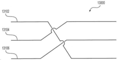
13A and 13B illustrate another exemplary wire braid pattern of an intraluminal device, consistent with various embodiments of the present disclosure.
예시적인 실시예에 대해 첨부 도면을 참조하여 기술한다. 반드시 축척대로 그려지지는 않은 도면에서, 도면부호의 맨 왼쪽 숫자는 도면부호가 처음으로 나타나는 도면을 식별한다. 편리하기만 하면, 도면 전체에 거쳐서 동일한 도면부호는 동일 또는 유사한 부분을 나타내기 위해 사용된다. 개시된 원리의 예 및 특징이 본 명세서에 기술되지만, 개시된 실시예의 사상 및 범위를 벗어나지 않으면서, 수정예, 개조예 및 다른 구현예가 실현 가능하다. 또한, "포함하는(comprising)", "갖는(having)", "들어있는(containing)" 및 "구비하는(including)" 및 기타 유사한 형태의 단어들은 의미가 동등하며, 이들 단어 중 어느 하나 다음에 나오는 항목 또는 항목들이 그러한 항목 또는 항목들의 완전한 목록인 것을 의미하거나 오직 나열된 항목 또는 항목들만에 한정되는 것을 의미하지는 않는다는 점에서 확장 가능한(open-ended) 것을 의도한다. 또한, 본 명세서 및 첨부된 청구범위에서 사용된 바와 같이, 단수 형태 "a", "an" 및 "the"는 문맥이 달리 명시하지 않는 한 복수 지시물을 포함한다는 점에 유의해야 한다.An exemplary embodiment will be described with reference to the accompanying drawings. In drawings that are not necessarily drawn to scale, the number to the left of the reference number identifies the drawing in which the reference number first appears. Where convenient, the same reference numerals are used throughout the drawings to indicate the same or similar parts. Although examples and features of the disclosed principles are described herein, modifications, adaptations, and other implementations are feasible without departing from the spirit and scope of the disclosed embodiments. In addition, words of "comprising", "having", "containing" and "including" and other similar forms are equivalent in meaning and after any one of these words It is intended to be open-ended in that the items or items appearing in are not meant to be a complete list of those items or items or to be limited to the listed items or items only. In addition, it should be noted that, as used in this specification and the appended claims, the singular forms “a”, “an” and “the” include plural indications unless the context dictates otherwise.
본 개시의 실시예는 개략적으로 신체의 폐색을 치료하기 위한 의료 장치 및 방법에 관한 것이다. 보다 구체적으로, 본 개시의 실시예는 혈관으로부터, 색전(emboli) 및 혈전(thrombi)을 포함하지만 이에 한정되지 않는 응괴를 제거하기 위한 장치 및 방법에 관한 것이다. 추가적으로 또는 대안적으로, 본 개시의 실시예는 또한 폐색된 중공의 신체 기관을 확장하기 위해 활용될 수 있을 뿐만 아니라, 막힘 또는 이물질의 제거가 요구되는 다른 의료적 처치에서도 사용될 수 있다.Embodiments of the present disclosure generally relate to medical devices and methods for treating body obstruction. More specifically, embodiments of the present disclosure relate to apparatus and methods for removing clots from blood vessels, including, but not limited to, emboli and thrombi. Additionally or alternatively, embodiments of the present disclosure may also be utilized not only to expand the occluded hollow body organs, but also to other medical treatments requiring the removal of blockages or foreign objects.
본 개시의 실시예에 따르면, 확장 가능한 응괴 결합 구성요소를 포함하는 관강내 장치가 제공될 수도 있다. 확장 가능한 응괴 결합 구성요소는 메쉬형 또는 스텐트형 구조체를 가질 수 있으며, 혈관과 같은 중공 신체 기관 내에서의 전개 및 확장시 혈액 응괴 또는 기타 폐색물을 포착, 유지 및 제거하도록 구성될 수도 있다.According to embodiments of the present disclosure, an intraluminal device may be provided that includes an expandable coagulation coupling component. The expandable clot bonding component may have a mesh-like or stent-like structure and may be configured to capture, retain, and remove blood clots or other obstructions upon deployment and expansion in hollow body organs such as blood vessels.
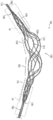
도 1은 예시적인 관강내 장치(1000)를 도시한다. 장치(1000)는 원위 케이블(1100), 근위 케이블(1200), 및 이들 사이의 확장 가능한 응괴 결합 구성요소(1300)를 포함할 수도 있다. 본 개시에서, "근위(proximal)"라는 용어는 사용 중에 장치 조작자에게 더 가까운 장치(예컨대, 장치(1000))의 단부를 나타내고, "원위(distal)"라는 용어는 사용 중에 장치 조작자로부터 더 멀리 있는 장치의 단부를 나타낸다. 장치(1000)는 근위 케이블(1200)로부터 응괴 결합 구성요소(1300)를 통해 원위 케이블(1100)로 연장되는 복수의 와이어 또는 필라멘트를 포함할 수도 있다. 장치(1000)는 8개의 와이어, 9개의 와이어, 10개의 와이어, 11개의 와이어, 12개의 와이어, 또는 임의의 다른 적절한 수의 와이어를 포함할 수도 있다. 제한 없이, 예컨대, 장치(1000)는 6개의 와이어, 7개의 와이어, 8개의 와이어, 9개의 와이어, 10개의 와이어, 11개의 와이어, 12개의 와이어, 13개의 와이어, 14개의 와이어, 15개의 와이어, 16개의 와이어, 17개의 와이어 또는 18개의 와이어를 포함할 수 있다. 몇몇 실시예에서, 복수의 와이어는 원위 케이블(1100) 및 근위 케이블(1200)을 형성하기 위해 케이블 축을 중심으로 권취될 수 있으며, 그 결과, 케이블들은 응괴 결합 구성요소(1300)의 확장 및 수축 동안 일정한 직경을 유지하도록 구성될 수도 있다. 원위 케이블(1100)은 원위 팁(1110)을 포함할 수 있는데, 원위 팁(1110)은 조직에 대해 비외상성이 되도록 둥글거나 다른 형태일 수도 있다. 몇몇 실시예에서, 근위 케이블(1200)은 응괴 결합 구성요소(1300)로부터 제어 핸들(도시 생략)까지 근위로 연장될 수도 있다. 대안적으로, 장치(1000)는 또한 근위 케이블(1200)에 대해 근위에 위치되며 근위 케이블(1200)과 제어 핸들 사이에서 연장되는 관형 샤프트를 포함할 수도 있다.1 shows an exemplary
몇몇 실시예에서, 와이어는 40 마이크론 내지 200 마이크론의 직경을 가질 수도 있다. 제한 없이, 예컨대, 장치(1000) 내의 와이어의 직경은 40 마이크론, 45 마이크론, 50 마이크론, 55 마이크론, 60 마이크론, 65 마이크론, 70 마이크론, 75 마이크론, 80 마이크론, 85 마이크론, 90 마이크론, 95 마이크론, 100 마이크론, 105 마이크론, 110 마이크론, 115 마이크론, 120 마이크론, 125 마이크론, 130 마이크론, 135 마이크론, 140 마이크론, 145 마이크론, 150 마이크론, 155 마이크론, 160 마이크론, 165 마이크론, 170 마이크론, 175 마이크론, 180 마이크론, 185 마이크론, 190 마이크론, 195 마이크론 및 200 마이크론, 또는 이들의 범위 중 어느 하나일 수 있다. 예컨대, 와이어는 50 마이크론 내지 75 마이크론 범위의 직경을 가질 수도 있다. 유리하게는, 직경이 50 마이크론 내지 75 마이크론인 와이어는 원위 케이블(1100)이 유연하여 사용 중에 조직에 대해 비외상성이도록 하면서도 여전히 신체 내에서의 치료적 사용을 위해 장치(1000)에 충분한 강성을 제공할 수 있다.In some embodiments, the wire may have a diameter of 40 microns to 200 microns. Without limitation, for example, the diameter of the wire in the
몇몇 실시예에서, 복수의 와이어는 확장 가능한 메쉬형 또는 스텐트형 구조체를 형성하도록 응괴 결합 구성요소(1300)에서 편조될 수도 있다. 메쉬형 구조체 내에서, 복수의 와이어는 연결되지 않고 서로 교차하도록 직조될 수 있으며, 이에 의해 와이어들은 서로에 대해 이동하도록 구성될 수도 있다. 몇몇 실시예에서, 와이어는 응괴 결합 구성요소(1300)의 근위 단부 및 원위 단부에 와이어의 노출된 단부가 없을 수 있으며 노출된 단부의 부재로 인해 해부학적 구조에 대한 외상이 감소할 수 있도록 메쉬형 구조체를 형성하도록 교차되고 굽혀질 수도 있다.In some embodiments, a plurality of wires may be braided in the
응괴 결합 구성요소(1300)는 반경방향으로 확장 및 수축하도록 구성될 수 있으며, 그에 따라, 응괴 결합 구성요소(1300)는 반경방향으로 수축된 구성과 반경방향으로 확장된 구성 사이에서 전이하도록 구성될 수도 있다. 몇몇 실시예에서, 응괴 결합 구성요소(1300)는 적어도 부분적으로 복수의 와이어의 배열 및 재료 구성으로 인해 자가 확장할 수도 있다. 예컨대, 관강내 장치(1000)는 응괴 결합 구성요소(1300)를 수축된 구성으로 유지할 수 있는 전달 시스(delivery sheath)(도시 생략) 내에서 치료 부위로 전달될 수도 있다. 시스에 대한 장치(1000)의 이동(예컨대, 시스의 원위 방향 후퇴)은 장치(1000)를 자유롭게 할 수 있으며 응괴 결합 구성요소(1300)의 확장을 허용할 수도 있다.The
추가적으로 또는 대안적으로, 장치(1000)는 응괴 결합 구성요소(1300)의 확장 및 수축을 제어할 수 있는 적어도 하나의 세장형 제어 부재(도시 생략)를 포함할 수도 있다. 제어 부재는 원위 케이블(1100) 주위에 및/또는 응괴 결합 구성요소(1300)의 원위 단부에 연결되거나, 그와 함께 짜여지거나, 루핑되거나(looped) 및/또는 매듭지어진 와이어 또는 필라멘트를 포함할 수도 있다. 제어 부재는 응괴 결합 구성요소(1300) 및 근위 케이블(1200) 내에서 또는 그에 평행하게 제어 핸들로 지나갈 수 있으며, 제어 핸들에서 장치 조작자는 제어 부재를 활용하여 응괴 결합 구성요소(1300)를 확장 또는 수축시킬 수 있다. 제어 부재는 응괴 결합 구성요소(1300)의 확장 또는 수축에 영향을 미치기 위해 장치(1000)의 일부에 힘을 가하도록 구성될 수도 있다. 예컨대, 제어 부재는 응괴 결합 구성요소(1300)의 원위 단부에 근위 방향 힘을 가하여 응괴 결합 구성요소를 반경방향으로 확장시키도록 구성될 수도 있다. 마찬가지로, 제어 부재는 응괴 결합 구성요소(1300)의 원위 단부에 원위 방향 힘을 가하여 응괴 결합 구성요소를 반경방향으로 수축시키도록 구성될 수도 있다.Additionally or alternatively, the
관강내 장치(1000)의 복수의 와이어는 당업자에게 공지된 임의의 적절한 가요성 재료로 이루어질 수도 있다. 적절한 가요성 재료는 중합체, 금속, 금속 합금 및 이들의 조합을 포함할 수 있지만 이에 한정되지 않는다. 몇몇 실시예에서, 예컨대 와이어는 니티놀(Nitinol)과 같은 초 탄성 금속으로 이루어질 수도 있다. 혈관 조영 영상으로 응괴 결합 구성요소(1300)를 시각화하기 위해, 와이어는 방사선 불투과성 마커 및/또는 물질을 추가로 포함할 수도 있다. 예컨대, 일 실시예에서, 장치(1000)는 탄탈 또는 백금 금속으로 만들어진 코어를 갖는 복수의 니티놀 와이어를 포함할 수도 있다. 방사선 불투과성 코어는 부피 기준으로 20% 내지 50%(예컨대, 30% 또는 40%)일 수 있다. 추가 실시예에서, 와이어는 백금과 같은 방사선 불투과성 금속의 얇은 층을 증착함으로써 방사선 불투과성이 되도록 만들어질 수 있다. 몇몇 실시예에서, 이러한 방사선 불투과성 특징부는 도 1의 응괴 결합 구성요소(1300)의 근위 단부 및 원위 단부에 위치될 수도 있다.The plurality of wires of the
앞서 언급한 바와 같이, 전달 시스가 제공될 수도 있다. 시스는 내부에 관강내 장치(1000)의 적어도 일부를 수용하도록 구성된 중공 관형 구조체일 수 있으며, 이에 따라 응괴 결합 구성요소(1300)를 포함하여 장치를 둘러싸서 반경방향으로 압축한다. 시스는 장치(1000)로부터 제거될 수 있어서 그에 의해 응괴 결합 구성요소(1300)가 시스가 배치된 혈관에서 반경방향으로 확장할 수 있게 한다. 몇몇 실시예에서, 장치(1000)는 시스 내에서 치료 부위(예컨대, 응괴 부위)로 전달될 수도 있다. 시스는 응괴 결합 구성요소(1300)의 제어된 확장 및 수축을 허용하도록 구성될 수도 있다. 예컨대, 앞서 논의된 바와 같이, 응괴 결합 구성요소(1300)는 시스의 제거시(예컨대, 시스가 근위 방향으로 후퇴될 때) 반경방향으로 확장하도록 구성될 수도 있다. 또한, 장치(1000)는 (예컨대, 장치(1000)를 근위 방향으로 시스 내로 끌어당기는 것에 의해) 시스 내로 복귀되어, 응괴 결합 구성요소(1300)가 수축된 구성으로 복귀하게 할 수도 있다.As mentioned above, a delivery sheath may be provided. The sheath may be a hollow tubular structure configured to receive at least a portion of the
관강내 장치(1000)는 혈액 응괴와 같은 폐색물을 포착하고 이를 신체로부터 제거하도록 구성될 수도 있다. 추가적으로 또는 대안적으로, 장치(1000)는 혈관과 같은 중공 신체 기관의 벽에 외향의 힘을 가하도록 구성될 수도 있다. 몇몇 실시예에서, 응괴 결합 구성요소(1300)는 확장된 구성에 있을 때 실질적으로 균일한 형상을 나타내도록 구성될 수도 있다. 대안적으로, 도 1에 도시된 바와 같이, 응괴 결합 구성요소(1300)는 확장된 구성에 있을 때 실질적으로 비대칭적인 형상을 나타내도록 구성될 수도 있다. 본 개시 내용과 부합하여, 비대칭 형상은 혈관의 해부학적 구조를 따르기 위한 응괴 결합 구성요소(1300)의 능력을 개선할 수도 있다.The
몇몇 실시예에서, 응괴 결합 구성요소(1300)의 적어도 일부는 혈액 응괴 부위에서 대략 혈관의 내경까지 확장하도록 구성될 수도 있다. 대략 혈관의 내경까지 확장하면, 응괴 결합 구성요소(1300)가 혈관 벽에 힘을 가하여 응괴가 혈관 벽으로부터 분리되도록 할 수 있다. 유리하게는, 혈관 벽으로부터의 응괴의 분리는 혈관 벽으로부터 응괴를 추가로 제거하는 데 필요한 힘의 양을 감소시키고 혈관으로부터의 제거 중에 응괴가 여러 개의 단편으로 쪼개지는 경향을 완화할 수도 있다. 수축된 구성에서, 응괴 결합 구성요소(1300)는 내부에 들어 있는 응괴에 힘을 가하여 응괴를 관강내 장치(1000) 내에 유지하고 응괴가 분열되는 경향을 완화할 수 있다. 그 후, 응괴는 오로지 응괴 결합 구성요소(1300) 내에 유지된 상태로 혈관으로부터 회수될 수도 있다. 대안적으로, 전달 시스 내에 들어갈 만큼 충분히 작은 응괴의 경우, 응괴는 혈관에서 제거되기 전에 전달 시스 내로 끌어당겨질 수도 있다. 이러한 방식으로, 전달 시스는 응괴에 추가적인 유지력을 가할 수도 있다.In some embodiments, at least a portion of the
몇몇 실시예에서, 응괴 결합 구성요소(1300)는 하나 이상의 응괴 포착 구역(1310, 1320), 원위 필터(1330) 및/또는 근위 필터(1340)를 포함할 수 있으며, 각각은 이를 통해 연장되는 와이어의 직조 패턴을 갖는다. 도 1의 예에서, 응괴 결합 구성요소(1300)는 2개의 응괴 포착 구역, 원위 필터 및 근위 필터를 포함한다. 그러나, 대안적인 실시예에서 응괴 결합 구성요소는 포착 구역, 원위 필터 및 근위 필터 중 하나 이상을 포함하지 않을 수도 있다. 또한, 대안적인 실시예에서 응괴 결합 구성요소는 1개, 3개, 4개, 5개 또는 그 이상의 응괴 포착 구역을 포함할 수도 있다. 근위 필터(1340)는 복수의 와이어가 그 사이에서 연장되는 상태로 전이부(1205)에서 근위 시스(1200)와 교차할 수 있다. 유사하게, 원위 필터(1330)는 복수의 와이어가 그 사이에서 연장되는 상태로 전이부(1105)에서 원위 시스(1100)와 교차할 수 있다. 포착 구역(1310, 1320)은 근위 필터와 원위 필터 사이에 위치될 수 있으며, 응괴 결합 구성요소(1300)가 확장된 구성에 있을 때 근위 필터 및 원위 필터보다 더 큰 직경을 가질 수도 있다. 몇몇 실시예에서, 두 포착 구역은 확장시에 동일한 직경을 가질 수 있으며, 대안적으로, 하나의 포착 구역은 확장시에 다른 포착 구역보다 더 큰 직경을 가질 수도 있다. 포착 구역(1310, 1320)은 동일하거나 상이한 와이어 직조 패턴을 가질 수도 있다. 예컨대, 포착 구역(1310, 1320) 중 하나 이상은 복수의 와이어 중 적어도 2개가 도 1의 꼬임(1312 및 1314)과 같은 서로 얽힌 와이어 조합을 형성하도록 서로 주위에 권취될 수 있는 와이어 직조 패턴을 가질 수도 있다. 도 1의 예에서, 2개의 와이어가 함께 권취되어 꼬임을 형성하는데, 그러나, 대안적인 실시예에서는 3개 이상의 와이어가 함께 권취되어 하나 이상의 포착 구역의 꼬임을 형성할 수도 있다. 와이어의 꼬임은 (예컨대, 응괴 결합 구성요소(1300)의 확장 및 수축 중에) 와이어의 미끄러짐을 방지할 수 있으며, 이들 사이에 큰 응괴 포착 윈도우(clot capturing window)(1316)를 형성할 수도 있다. 윈도우(1316)는 더 큰 응괴 및 기타 폐색물을 포착하고 유지할 수 있다. 원위 필터(1330) 및 근위 필터(1340)는 동일하거나 상이한 와이어 직조 패턴을 가질 수 있는데, 이는 포착 구역(1310, 1320)의 직조 패턴과 상이할 수도 있다. 원위 필터(1330) 및 근위 필터(1340) 중 하나 이상의 직조 패턴은 포착 구역(1310, 1320)에 대한 구조적 지지를 제공할 수도 있다. 또한, 원위 필터 및 근위 필터의 와이어들 사이의 개구는 응괴 포착 윈도우(1316)보다 작을 수도 있으며, 그에 따라, 원위 필터(1330) 및 근위 필터(1340)는 구역(1310, 1320)에 의해 포착되기에는 너무 작을 수 있는 폐색물을 포착하고 유지하도록 구성될 수도 있다.In some embodiments, the
몇몇 실시예에서, 복수의 와이어 중 하나 이상은 인접 세그먼트의 다른 와이어들에 대한 연결 또는 부착(예컨대, 용접 또는 접착) 없이 근위 케이블(1200), 응괴 결합 구성요소(1300) 및 원위 케이블(1100)을 통해 연속적으로 연장될 수도 있다. 즉, 하나 이상의 와이어의 길이는 장치(1000)의 원위 단부로부터 장치(1000)의 근위 단부까지 연장될 수도 있다. 예컨대, 몇몇 실시예에서 장치(1000)의 모든 와이어는 장치(1000)의 원위 단부로부터 장치(1000)의 근위 단부까지 연속적으로 연장될 수도 있다. 그 결과, 복수의 와이어의 각각의 와이어가 전술한 바와 같이 근위 케이블(1200), 응괴 결합 구성요소(1300) 및 원위 케이블(1100)을 통해 연속적으로 연장되도록 구성되는 경우, 근위 케이블(1200), 응괴 결합 구성요소(1300) 및 원위 케이블(1100)은 하나의 단일 구조로 제조될 수 있으며, 그에 따라 근위 케이블(1200), 응괴 결합 구성요소(1300) 및 원위 케이블(1100)은 별도로 제조되고 함께 용접, 접착 또는 그와 다른 방식으로 부착되지는 않을 것이다. 이러한 구성은 도 1 내지 도 3b에 도시되어 있는데, 복수의 와이어 각각은 전이부(1105 및 1205)의 관통을 포함하여 관강내 장치(1000)의 길이를 따라 연속적으로 통과할 수도 있다. 또한, 복수의 와이어 각각의 몸체가 근위 케이블(1200)로부터 원위 케이블(1100)까지(예컨대, 원위 팁(1110)까지) 연장될 수 있도록 각각의 와이어에는 간극 및 불연속부가 없을 수도 있다.In some embodiments, one or more of the plurality of wires may include
도 2a는 관강내 장치(1000)의 원위 전이부 영역의 확대도를 도시한다. 도 2a는 전이부(1105)뿐만 아니라 원위 케이블(1100) 및 원위 필터(1330)의 일부를 도시한다. 몇몇 실시예에서, 장치(1000)의 연속적인 편조로 인해, 원위 필터(1330) 내의 모든 와이어는 전이부(1105)를 통해 원위 케이블(1100)로 연속적으로 연장될 수 있으며, 원위 방향으로 원위 팁(1110)까지 연장될 수도 있다. 도 2a에 도시된 바와 같이, 와이어는 중단 또는 간극 없이 전이부(1105)을 통해 연장될 수도 있다. 대안적으로, 하나 이상의 와이어가 전이부(1105)에서 또는 그 근처에서 절단되거나 또는 그와 다른 방식으로 분리될 수도 있다.2A shows an enlarged view of the distal transition region of the
도 2a에 도시된 바와 같이, 원위 필터(1330)는 폐색물(예컨대, 응괴)을 포착하기 위해 내부에 다수의 개구(2005, 2010)를 포함하는 와이어 직조 패턴을 가질 수도 있다. 개구(2005, 2010)는 응괴 포착 윈도우(1316)보다 작을 수 있으며 따라서 응괴 포착 윈도우(1316)보다 더 작은 폐색물 및 응괴를 포착하도록 구성될 수도 있다. 몇몇 실시예에서, 하나 이상의 방사선 불투과성 마커가, 예컨대 장치 조작자에 의해, 응괴 결합 구성요소(1300)의 원위 단부가 시각화될 수 있도록 전이부(1105)에 또는 그 근처에 위치될 수도 있다.As shown in FIG. 2A, the
몇몇 실시예에서, 원위 케이블(1100) 내의 와이어들은 그로부터 재료를 제거하기 위해 화학적으로 또는 전기 화학적으로 처리되어, 장치(1000)의 더 부드럽고 더욱 비외상적인 팁을 형성한다. 이는 에칭, 전해 연마 또는 기타 적절한 화학적 또는 전기 화학적 공정에 의해 달성될 수 있다. 원위 케이블(1100)에서의 와이어의 직경을 줄임으로써, 와이어는 더 유연하고 부드러워질 수 있으며, 따라서 와이어는 신체 내에서의 사용 동안 조직에 손상을 적게 줄 수도 있다.In some embodiments, the wires in the
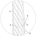
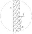
도 2b는 원위 케이블(1100)의 확대도를 도시한다. 위에서 논의된 바와 같이, 원위 케이블 내의 와이어의 수 및 직경은 케이블 권취 각도(2300)를 결정할 수 있다. 도 2b에 도시된 바와 같이, 케이블 권취 각도(2300)는 와이어 축(2400)에 수직인 횡축(2500)과 와이어(2600)의 방향 사이에 형성된 각도일 수도 있다. 몇몇 실시예에서, 원위 케이블(1100)은 근위 케이블(1200)(예컨대 11개 또는 12개의 와이어)보다 더 적은 와이어(예컨대, 8개의 와이어)를 포함할 수 있으며, 따라서 더 작은 케이블 권취 각도(2300)를 허용하고 그에 따라 더 부드럽고 더 유연한 원위 케이블을 허용한다.2B shows an enlarged view of the
도 3a는 관강내 장치(1000)의 근위 전이부 영역의 확대도를 도시한다. 도 3a는 전이부(1205)뿐만 아니라 근위 필터(1340) 및 근위 케이블(1200)의 일부를 도시한다. 몇몇 실시예에서, 장치(1000)의 연속적인 편조로 인해, 근위 케이블(1200) 내의 모든 와이어는 전이부(1205)를 통해 근위 필터(1340)까지 연속적으로 연장될 수도 있다. 도 3a에 도시된 바와 같이, 와이어는 중단 또는 간극 없이 전이부(1205)을 통해 연장될 수도 있다. 대안적으로, 하나 이상의 와이어가 전이부(1205)에서 또는 그 근처에서 절단되거나 또는 그와 다른 방식으로 분리될 수도 있다.3A shows an enlarged view of the proximal transition region of the
도 3a에 도시된 바와 같이, 근위 필터(1340)는 폐색물(예컨대, 응괴)을 포착하기 위해 내부에 다수의 개구(3005, 3010)를 포함하는 와이어 직조 패턴을 가질 수도 있다. 개구(3005, 3010)는 응괴 포착 윈도우(1316)보다 작을 수 있으며, 따라서 응괴 포착 윈도우(1316)보다 더 작은 폐색물 및 응괴를 포착하도록 구성될 수도 있다. 몇몇 실시예에서, 하나 이상의 방사선 불투과성 마커가, 예컨대 장치 조작자에 의해, 응괴 결합 구성요소(1300)의 근위 단부가 시각화될 수 있도록 전이부(1205)에 또는 그 근처에 위치될 수도 있다.As shown in FIG. 3A, the
도 3b는 근위 케이블(1200)의 확대도를 도시한다. 근위 케이블(1200)은 근위 케이블 내의 와이어의 수 및 직경에 의해 결정되는 케이블 권취 각도(3300)를 가질 수도 있다. 도 3b에 도시된 바와 같이, 케이블 권취 각도(3300)는 와이어 축(3400)에 수직인 횡축(3500)과 와이어(3600)의 방향 사이에 형성된 각도일 수도 있다. 몇몇 실시예에서, 근위 케이블 권취 각도(3300)는 근위 케이블(1200)이 원위 케이블(1100)보다 더 많은 와이어 및/또는 더 큰 직경의 와이어를 갖기 때문에 원위 케이블 권취 각도(2300)보다 클 수도 있다. 예컨대, 원위 케이블 권취 각도(2300)는 5°(예컨대, 매우 작은 각도를 갖는, 도 7을 참조하여 아래에서 논의되는 바와 같이, 단일 가닥 케이블에서) 내지 60°의 각도인 반면에, 근위 케이블 권취 각도(3300)는 50° 내지 60°의 각도일 수도 있다. 그 결과, 원위 케이블(1100)은 근위 케이블(1200)보다 더 부드럽고 더 유연할 수도 있다. 대안적인 실시예에서, 원위 케이블(1100)은 원위 케이블 권취 각도(2300)가 60° 내지 70°이도록 배열될 수도 있다. 제한 없이, 예컨대, 원위 케이블 권취 각도(2300)는 1°, 2°, 3°, 4°, 5°, 8°, 10°, 12°, 15°, 20°, 25°, 30°, 35°, 40°, 45°, 50°, 55°, 60°, 65° 또는 70°의 각도를 가질 수도 있다. 또한, 제한 없이, 근위 케이블 권취 각도(3300)는 40°, 45°, 50°, 51°, 52°, 53°, 54°, 55°, 56°, 57°, 58°, 59°, 60°, 65° 또는 70°의 각도를 가질 수도 있다.3B shows an enlarged view of the
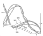
도 4는 다른 예시적인 관강내 장치(4000)를 도시한다. 장치(4000)는 원위 케이블(4100), 근위 케이블(4200) 및 이들 사이의 확장 가능한 응괴 결합 구성요소(4300)를 포함할 수도 있다. 장치(4000)는 복수의 와이어로 형성될 수 있는데, 복수의 와이어는 확장 가능한 메쉬형 또는 스텐트형 구조체를 형성하도록 응괴 결합 구성요소(4300)에서 편조될 수도 있다. 몇몇 실시예에서, 와이어는 전이부(4105 및 4205)의 관통을 포함하여 장치(4000)의 근위 단부로부터 장치(4000)의 원위 단부까지 연속적으로 연장될 수도 있다.4 shows another exemplary
응괴 결합 구성요소(4300)는 원하는 메쉬 배열을 달성하기 위해 사전 결정된 수의 와이어를 포함할 수도 있다. 응괴 결합 구성요소(4300)는 하나 이상의 권취된 와이어 쌍(4330) 및/또는 3개의 권취된 와이어로 이루어진 하나 이상의 케이블(4320)을 포함할 수도 있다. 응괴 포착 윈도우(4316)는 쌍들(4330) 및/또는 케이블들(4320) 사이에 형성될 수도 있다. 예컨대, 응괴 결합 구성요소(4300)는 4개의 와이어 쌍(4330)으로 형성된 8개의 와이어를 포함할 수도 있다. 대안적인 예에서, 응괴 결합 구성요소(4300)는 2개의 와이어 쌍(4330) 및 2개의 와이어 케이블(4320)로 형성된 10개의 와이어를 포함할 수도 있다. 다른 예에서, 응괴 결합 구성요소(4300)는 4개의 와이어 케이블(4320)로 형성된 12개의 와이어를 포함할 수도 있다. 또 다른 예에서, 응괴 결합 구성요소(4300)는 6개의 와이어 쌍(4330)으로 형성된 12개의 와이어를 포함할 수도 있다. 대안적으로, 응괴 결합 구성요소(4300)는 임의의 다른 적절한 개수의 와이어 쌍(4330) 및/또는 와이어 케이블(4320)로 형성될 수도 있다.The
도 5는 관강내 장치(4000)의 예시적인 와이어 교차부(5000)를 도시한다. 교차부(5000)는 하나의 교차부에서 2개의 와이어 쌍(4330)이 만나는 것에 의해 형성될 수도 있다. 각각의 와이어 쌍은 교차부(5000)의 원위 및 근위에서 꼬일 수도 있다. 도 5에 도시된 바와 같이, 와이어(5102, 5104)는 교차부에 대해 원위에 있는 쌍 꼬임(5106) 및 교차부에 대해 근위에 있는 쌍 꼬임(5108)에서 서로에 대해 꼬일 수도 있다. 마찬가지로, 와이어(5202, 5204)는 교차부에 대해 원위에 있는 쌍 꼬임(5206) 및 교차부에 대해 근위에 있는 쌍 꼬임(5208)에서 서로에 대해 꼬일 수도 있다.5 shows an exemplary wire crossing 5000 of an
교차부(5000)에서, 각각의 와이어 쌍은 다른 와이어 쌍의 오직 하나의 와이어만을 둘러쌀 수도 있다. 예컨대, 도 5에 도시된 바와 같이, 와이어(5102, 5104)는 교차부에서 와이어(5204)를 둘러싸지만 와이어(5202)를 둘러싸지는 않을 수도 있다. 마찬가지로, 와이어(5202, 5204)는 교차부에서 와이어(5102)를 둘러싸지만 와이어(5104)를 둘러싸지는 않을 수도 있다. 유리하게는, 이러한 교차 배열은 각 와이어 쌍이 다른 쌍을 따라 슬라이딩할 수 없도록 두 와이어 쌍을 서로에 대해 고정시킬 수 있는 한편, 두 와이어 쌍 사이의 최소한의 물리적 결합으로 인해 두 와이어 쌍 사이의 마찰을 최소화한다. 예컨대, 교차부(5000)는, 와이어(5102, 5104)가 와이어(5202, 5204)에 대해 축방향으로 슬라이딩하는 일 없이, 구성요소(4300)의 확장 및 수축 동안 와이어(5202, 5204)에 대해 피벗하도록 구성된 와이어(5102, 5104)에 의해, 응괴 결합 구성요소(4300)의 확장 및 수축 동안 힌지로서 기능하도록 구성될 수도 있다. 교차부(5000)에서의 두 와이어 쌍 사이의 최소한의 물리적 결합으로 인해, 각 와이어의 피벗 방향을 따른 마찰이 감소될 수 있어서, 와이어들이 교차부(5000)에서 분리되는 일 없이 더 낮은 적용된 힘에 응답하여 더 쉽게 피벗할 수 있다. 유리하게는, 교차부(5000)에서의 마찰을 극복하고 그에 따라 응괴 결합 구성요소(4300)를 확장 또는 수축시키기 위해 더 적은 힘이 요구될 수도 있다. 또한, 교차부(5000) 내의 어떠한 소정 지점에서도 2개 이하의 와이어가 접촉한다. 그 결과, 응괴 결합 구성요소(4300)의 직경에 추가된 두께는 2개의 상호 작용하는 와이어들의 직경의 합보다 크지 않다. 유리하게는, 이것은 응괴 결합 구성요소(4300)가 예컨대 전달 시스 내에서 전달되는 동안 최소화된 직경을 갖도록 허용하여, 장치(4000)가 작고 구불구불한 해부학적 구조를 통과할 수 있게 한다.At
도 6a 내지 도 6c는 관강내 장치의 예시적인 제조 방법을 도시한다. 도 6a 내지 도 6c에 도시된 예는 예시적인 관강내 장치(6000)의 제조를 나타내지만, 당업자는 본 명세서에 개시된 제조 방법이 관강내 장치(1000, 4000 및 7000)를 포함하고 이에 한정되지 않는 임의의 적절한 관강내 장치를 제조하는 데 사용될 수도 있음을 이해할 것이다.6A-6C illustrate an exemplary method of manufacturing an intraluminal device. The examples shown in FIGS. 6A-6C illustrate the manufacture of an exemplary
예시적인 관강내 장치(6000)는 원위 케이블(6100), 근위 케이블(6200), 및 이들 사이의 확장 가능한 응괴 결합 구성요소(6300)를 포함할 수도 있다. 장치(6000)는 복수의 와이어로 형성될 수 있는데, 복수의 와이어는 전이부 영역(6105 및 6205)의 관통을 포함하여 장치(6000)의 근위 단부로부터 장치(6000)의 원위 단부까지 연속적으로 연장될 수도 있다. 관강내 장치(6000)는 복수의 와이어를 맨드릴(6500) 상에 편조함으로써 형성될 수도 있다. 맨드릴(6500)은, 근위 케이블(6200)이 그 위에 형성될 수 있는 제 1 부분(6510), 응괴 결합 구성요소(6300)가 그 위에 형성될 수 있는 제 2 부분(6520), 및 원위 케이블(6100)이 그 위에 형성될 수 있는 제 3 부분(6530)을 가질 수 있으며, 맨드릴(6500)의 각 부분은 각자의 형상 및 직경을 갖는다. 예컨대, 맨드릴의 제 2 부분(6520)은 맨드릴의 제 1 부분(6510) 및 제 3 부분(6530) 각각보다 더 큰 직경을 가질 수도 있다. 그 결과, 응괴 결합 구성요소(6300)는 형성될 때 원위 케이블(6100) 및 근위 케이블(6200) 각각보다 더 큰 직경을 가질 수도 있다. 몇몇 실시예에서, 맨드릴의 제 1 부분(6510) 및 맨드릴의 제 3 부분(6530)은 원위 케이블(6100) 및 근위 케이블(6200)이 또한 실질적으로 동일한 직경을 갖도록 실질적으로 동일한 직경을 가질 수도 있다. 몇몇 대안적인 실시예에서, 맨드릴의 제 1 부분(6510)은 원위 케이블(6100)과 근위 케이블(6200)의 직경이 동일하지 않도록 맨드릴의 제 3 부분(6530)보다 더 크거나 더 작은 직경을 가질 수도 있다. 그러나, 본 개시에 부합하는 예시적인 맨드릴(6500)은 임의의 특정 형상, 치수 또는 구성에 한정되지 않는다. 예컨대, 맨드릴(6500)은 그 종방향 길이를 따라 대칭적으로 또는 비대칭적으로 외부 치수가 변할 수 있으며, 실질적으로 선형, 곡선형 또는 둘 모두의 조합일 수도 있다. 몇몇 실시예에서, 맨드릴(6500)의 형상, 치수 및 구성은 맨드릴(6500) 상에서 적어도 부분적으로 형성될 수 있는 관강내 장치(6000)의 원하는 형상 및 크기를 생성하도록 선택될 수도 있다.Exemplary
도 6a 내지 도 6c에 도시된 바와 같이, 복수의 와이어는 관강내 장치(6000)(원위 케이블(6100), 근위 케이블(6200) 및 응괴 결합 구성요소(6300)를 포함함)를 하나의 단일 구조로 형성하기 위해 맨드릴(6500)을 따라 연속적으로 편조될 수도 있다. 도 6a 내지 도 6c에서의 예시를 위해, 와이어와 맨드릴(6500) 사이에 약간의 공간이 표시되어 있다. 그러나, 실제로는, 맨드릴(6500)은 와이어가 그에 대해 감기는 형태로 작용할 수도 있다. 몇몇 실시예에서, 도 6a 내지 도 6c에 도시된 예와 같이, 와이어는 관강내 장치(6000)의 근위 단부로부터 시작해서 장치(6000)의 원위 단부를 향해 원위 방향으로 작용하여 맨드릴(6500) 상에 연속적으로 편조될 수도 있다. 그러나, 대안적인 실시예에서, 와이어는 장치(6000)의 원위 단부로부터 장치(6000)의 근위 단부를 향해 연속적으로 편조될 수도 있다.6A-6C, a plurality of wires comprises an intraluminal device 6000 (including a
도 6a에 도시된 바와 같이, 와이어는 근위 케이블(6200)을 형성하기 위해 제 1 맨드릴 부분(6510) 주위에 권취될 수도 있다. 전이부 영역(6205)에 도달하면(몇몇 실시예에서, 제 1 맨드릴 부분(6510)과 제 2 맨드릴 부분(6520) 사이의 교차점에 또는 그 근처에 형성될 수 있음), 복수의 와이어는 응괴 결합 구성요소(6300)를 형성하기 위해 제 2 맨드릴 부분(6520) 상에서 메쉬형 또는 스텐트형 배열로 편조될 수도 있다. 이것은 도 6b에 도시되어 있다. 몇몇 실시예에서, 근위 케이블(6200)을 형성하는 모든 와이어는 전이부 영역(6205)을 통과할 수 있고 응괴 결합 구성요소(6300)를 통해 연장될 수 있는데, 그러나, 와이어의 편조 패턴은 근위 케이블(6200)과 응괴 결합 구성요소(6300) 사이에서 상이할 수도 있다. 응괴 결합 구성요소(6300)의 형성을 완료하고 전이부 영역(6105)(몇몇 실시예에서 제 2 맨드릴 부분(6520)과 제 3 맨드릴 부분(6530) 사이의 교차점에 또는 그 근처에 형성될 수 있음)에 도달하면, 복수의 와이어는 원위 케이블(6100)을 형성하기 위해 제 3 맨드릴 부분(6530) 주위에 권취될 수도 있다. 몇몇 실시예에서, 응괴 결합 구성요소(6300)를 형성하는 모든 와이어는 전이부 영역(6105)을 통과할 수 있고 원위 케이블(6100)을 통해 연장할 수 있는데, 그러나, 와이어의 편조 패턴은 원위 케이블(6100)과 응괴 결합 구성요소(6300) 사이에서 상이할 수도 있다. 와이어는 장치(6000)의 원위 단부가 형성될 때까지 제 3 맨드릴 부분(6100) 주위에 권취될 수 있으며, 도 6c는 맨드릴(6000) 상의 완성된 장치(6000)를 도시한다.As shown in FIG. 6A, the wire may be wound around the
유리하게는, 장치(6000)의 부분들 사이의 연결 또는 부착의 결여는 보다 매끄러운 장치 프로파일을 초래할 수도 있다. 용접 또는 접착과 같은 연결 방법은 신체 내에서 장치를 사용하는 동안 조직을 긁어낼 수 있는 거칠고 돌출된 표면 특징부를 유발할 수 있다. 장치(6000)에는 와이어의 연속적인 편조로 인해 이러한 표면 특징부들이 없을 수 있기 때문에, 장치의 프로파일이 매끄러워서 신체를 통한 전달 중에 그리고 치료 부위에서의 장치의 사용 중에 외상을 적게 입힐 수 있다. 또한, 연속 편조 방법은 용접과 같이 서로 다른 장치 부분들을 함께 연결해야 하는 기술보다 더 간단하고 시간이 덜 소요될 수도 있다.Advantageously, a lack of attachment or connection between portions of the
몇몇 실시예에서, 형성된 관강내 장치(6000)의 적어도 일부는 맨드릴(6500)로부터 제거되기 전에 열처리될 수도 있다. 몇몇 실시예에서, 전체 관강내 장치(6000)가 열처리될 수도 있다. 대안적으로, 응괴 결합 구성요소(6300) 전체가 열처리될 수도 있다. 예컨대, 응괴 결합 구성요소(6300)는 내부의 와이어 부분들이 제 2 맨드릴 부분(6520)의 직경 및 형상에서의 형상 기억을 가질 수 있도록 열처리될 수도 있다. 다른 대안예에서, 응괴 결합 구성요소(6300)의 일부가 열처리될 수도 있다. 예컨대, 예시적인 관강내 장치(6000)가 맨드릴(6500) 상에 남아 있는 동안 열처리가 일어날 수도 있다. 열 처리는 장치(6000) 또는 그의 부분을 향해 있는 열풍 송풍기에 의해 수행될 수 있거나, 임의의 다른 장치 또는 방법에 의해 가해지는 열을 사용하여 수행될 수도 있다. 다른 가열 장치 또는 가열 방법은 대류, 전도 또는 둘 모두를 포함할 수도 있다. 예컨대, 맨드릴(6500)은 관강내 장치(6000)의 하나 이상의 부분에 전도에 의해 열을 가하기 위해 가열될 수도 있다. 열처리의 일 예는 장치(6000)가 맨드릴(6500) 상에 유지되는 동안 장치(6000) 또는 그의 부분에 적어도 약 450℃의 열을 가하는 것을 포함할 수도 있다. 다른 예에서, 열처리는 장치(6000) 또는 그의 부분에 약 500℃, 또는 480℃ 내지 550℃의 열을 가하는 것을 포함할 수도 있다. 또 다른 예에서, 열처리는 장치(6000)의 와이어(예컨대, 응괴 결합 구성요소(6300) 내의 와이어 부분)가 맨드릴(6500) 직경의 전체 또는 부분 기억(기억은 장치(6000)가 이후에 사용될 때 해당 직경으로 부분적으로 또는 완전히 복귀할 수 있는 능력임)을 갖도록 할 수 있는 임의의 온도에서 적용될 수 있다.In some embodiments, at least a portion of the formed
도 7은 다른 예시적인 관강내 장치(7000)를 도시한다. 장치(7000)는 원위 케이블(7100), 근위 케이블(7200), 및 이들 사이의 확장 가능한 응괴 결합 구성요소(7300)를 포함할 수도 있다. 장치(7000)는 복수의 와이어로 형성될 수 있는데, 복수의 와이어는 확장 가능한 메쉬형 또는 스텐트형 구조체를 형성하도록 응괴 결합 구성요소(7300)에서 편조될 수도 있다. 몇몇 실시예에서, 장치(7000)의 하나 이상의 와이어는 장치(7000)의 편조 동안 (예컨대, 전이부(7105) 또는 전이부(7205)에서) 절단되거나 또는 그와 다른 방식으로 분리될 수 있으며, 그 결과, 장치(7000)의 일부 부분은 다른 부분보다 더 많은 와이어를 가질 수도 있다. 예컨대, 근위 케이블(7200)은 원위 케이블(7100) 및 응괴 결합 구성요소(7300)보다 더 많은 와이어를 가질 수도 있다. 추가적으로 또는 대안적으로, 응괴 결합 구성요소(7300)는 원위 케이블(7100)보다 더 많은 와이어를 가질 수도 있다. 도 7에 도시된 예에서, 근위 케이블(7200)은 15개의 와이어를 포함하는 반면에, 원위 케이블(7100) 및 응괴 결합 구성요소(7300)는 12개의 와이어를 포함한다. 그러나, 당업자는 장치(7000)의 다양한 섹션(즉, 원위 케이블(7100), 근위 케이블(7200) 및 응괴 결합 구성요소(7300))이 임의의 원하는 수의 와이어를 포함할 수도 있음을 이해할 것이다. 예컨대, 몇몇 실시예에서, 근위 케이블(7200)은 11개의 와이어를 가질 수 있고, 그 중 3개가 전이부(7205)에서 또는 그 근처에서 절단될 수 있으며, 그 결과, 응괴 결합 구성요소(7300) 및 원위 케이블(7100)은 8개의 와이어를 가질 수도 있다. 몇몇 대안적인 실시예에서, 근위 케이블(7200)은 12개의 와이어를 가질 수 있고, 그 중 4개가 전이부(7205)에서 또는 그 근처에서 절단될 수 있으며, 그 결과, 응괴 결합 구성요소(7300) 및 원위 케이블(7100)은 8개의 와이어를 가질 수도 있다. 제한 없이, 예컨대, 원위 케이블(7100)은 1개의 와이어, 2개의 와이어, 3개의 와이어, 4개의 와이어, 5개의 와이어, 6개의 와이어, 7개의 와이어, 8개의 와이어, 9개의 와이어, 10개의 와이어, 11개의 와이어, 12개의 와이어, 13개의 와이어, 14개의 와이어 또는 15개의 와이어를 가질 수도 있다. 또한, 제한 없이, 응괴 결합 구성요소(7300)는 6개의 와이어, 7개의 와이어, 8개의 와이어, 9개의 와이어, 10개의 와이어, 11개의 와이어, 12개의 와이어, 13개의 와이어, 14개의 와이어, 15개의 와이어 또는 16개의 와이어를 가질 수도 있다. 또한, 제한 없이, 근위 케이블(7200)은 8개의 와이어, 9개의 와이어, 10개의 와이어, 11개의 와이어, 12개의 와이어, 13개의 와이어, 14개의 와이어, 15개의 와이어, 16개의 와이어, 17개의 와이어 또는 18개의 와이어를 가질 수도 있다.7 shows another exemplary
유리하게는, 장치(7000)의 세그먼트들에 상이한 개수의 와이어를 통합하는 것은 각 세그먼트가 와이어 수, 와이어 직경, 케이블 강성 및 편조 배열을 포함하여 별개의 물리적 특성을 갖도록 허용할 수 있다. 그 결과, 장치(7000)의 각 세그먼트는 다른 세그먼트의 원하는 물리적 특성과 상이할 수 있는 원하는 물리적 특성을 갖도록 구성될 수도 있다. 예컨대, 원위 케이블(7100) 및 근위 케이블(7200)의 코일을 형성하는 와이어의 수와 이들 와이어의 직경은 케이블의 강성에 영향을 미치는 케이블 권취 각도를 결정할 수도 있다. 더 적은 수의 와이어 및/또는 더 작은 직경의 와이어를 사용하면, 더 작은 케이블 권취 각도를 허용하여 덜 단단하고 더 유연한 케이블을 만들 수도 있다. 따라서, 몇몇 실시예에서 원위 케이블(7100)은 원위 케이블(7100)이 근위 케이블(7200)보다 더 부드럽고 덜 단단하도록 근위 케이블(7200)보다 더 작은 직경의 와이어 및/또는 더 적은 수의 와이어를 포함할 수도 있다. 이는 장치(7000)가 부드럽고 비외상적인 원위 팁 및 더 단단한 근위 케이블을 구비하게 할 수 있다.Advantageously, incorporating a different number of wires into segments of
또한, 응괴 결합 구성요소(7300) 및 전이부(7105, 7205) 내의 와이어의 수는 메쉬형 구조체의 구조 및 물리적 특성에 영향을 미칠 수 있다. 예컨대, 응괴 결합 구성요소(7300) 및 전이부(7105, 7205) 내에 특정 수의 와이어를 사용하면, 수축 및 확장 구성에서의 메쉬 크기 및 직경, 응괴 결합 구성요소(7300) 내의 개구의 패턴 및 크기, 및 전달 시스를 통한 메쉬형 구조체의 전달 가능성을 포함하여 원하는 메쉬 배열이 형성될 수 있다.In addition, the number of wires in the
나아가, 근위 케이블(7200)에서의 와이어의 권취 각도는 케이블(7200)이 축방향으로 가해지는 힘 하에서 늘어나고 압축되는 경향에 영향을 미칠 수도 있다. 도 2b 및 도 3b과 관련하여 위에서 논의된 바와 같이, 케이블의 권취 각도는 케이블 내의 와이어의 방향과 케이블의 횡방향의 축 사이에 형성된 각도일 수도 있다. 케이블의 결과적인 권취 각도는 케이블이 그 위에 형성되는 맨드릴의 직경, 케이블 내 와이어의 수 및 케이블 내 와이어의 직경의 함수일 수도 있다. 구체적으로, 더 큰 직경의 맨드릴, 더 적은 수의 와이어 및 더 작은 직경의 와이어를 사용하면, 각각이 권취 각도를 줄이는 데 기여한다. 몇몇 실시예에서, 제한 없이, 근위 케이블(7200)은 40°, 45°, 50°, 51°, 52°, 53°, 54°, 55°, 56°, 57°, 58°, 59°, 60°, 65° 또는 70°의 권취 각도를 가질 수도 있다. 그 결과, 근위 케이블(7200)은 가해진 인장력 하에서 축방향 변형에 저항하여 오히려 일정한 축방향 길이를 유지할 수도 있다. 유리하게는, 응괴 회수 동안, 근위 케이블(7200)의 이러한 와이어 배열은 인장력이 가해질 때 축방향 신장에 저항할 수 있어서, 원활한 응괴 회수를 가능하게 한다. 세장형 제어 부재가 당겨지고 인장되어 응괴 결합 구성요소(7300)를 확장 및 수축시키는 다른 예에서, 근위 케이블(7200)은 세장형 제어 부재에 의해 가해지는 압축력 하에서 단축(shortening)에 저항할 수도 있다.Furthermore, the winding angle of the wire in the
예시적인 관강내 장치(7000)는 도 6a 내지 도 6c에 도시된 것과 유사한 제조 방법에 의해 형성될 수 있는데, 사전 결정된 부분(예컨대, 전이부 영역(7105) 및/또는 전이부 영역(7205) 또는 그 근처)에서 하나 이상의 와이어를 절단하거나 그와 다른 방식으로 분리하는 추가 단계를 포함한다. 예컨대, 전이부 영역(7205)에서 또는 그 근처에서 적어도 하나의 와이어를 절단 또는 분리함으로써, 응괴 결합 구성요소(7300) 및 원위 케이블(7100)을 통해 연장되는 와이어의 수가 감소될 수도 있다. 전이부 영역(7105) 또는 그 근처에서도 마찬가지로 하나 이상의 와이어가 절단 또는 분리될 수도 있다. 나머지 절단되지 않은 와이어들은 장치(7000)의 나머지 부분을 형성하기 위해 편조될 수도 있다. 대안적으로, 전이부 영역(7105, 7205) 중 하나에서 와이어가 절단되지 않을 수도 있다. 몇몇 실시예에서, 절단된 와이어의 단부는 글루(glue) 또는 접착제(adhesive)로 덮일 수 있으며 및/또는 마커 밴드로 덮일 수도 있다. 그 결과, 절단된 와이어로 인한 날카로운 에지는 환자의 부상을 방지하기 위해 가려질 수 있다.The exemplary
도 8a, 도 8b, 도 9 및 도 10은 예시적인 관강내 장치의 와이어에 대한 예시적인 와이어 교차부(8000, 9000 및 10000)를 도시한다. 몇몇 실시예에서, 와이어 교차부(8000, 9000 및 10000)는 응괴 결합 구성요소(1300, 4300, 6300 및 7300)와 같은 메쉬형 또는 스텐트형 구조체 내에서 활용될 수 있다. 와이어 교차부(8000, 9000 및 10000)는 사전 결정된 수의 와이어로 구성된 와이어 패턴 내에 관계 없는 와이어(extraneous wire)를 내장하거나 "숨기는" 것을 허용할 수도 있다. 예컨대, 장치 세그먼트 내에 8-와이어 패턴이 필요하지만 그 세그먼트에 10개의 와이어가 있는 경우, 8-와이어 패턴이 달성될 수 있도록 2개의 관계 없는 와이어를 내장하고 효과적으로 "숨기기" 위해 하나 이상의 예시적인 와이어 교차부(8000, 9000 및 10000)가 활용될 수도 있다.8A, 8B, 9 and 10 show
와이어 교차부(8000, 9000 및 10000)는 도 7과 관련하여 위에서 논의된 바와 같이 상이한 물리적 특성을 갖는 장치 세그먼트를 달성하기 위해 대안적인 기술을 제공할 수도 있다. 예컨대, 12-와이어 근위 케이블과 9-와이어 패턴의 메쉬 세그먼트를 갖는 관강내 장치가 요구되는 경우, 하나 이상의 와이어 교차부(8000, 9000 및 10000)를 메쉬 세그먼트에 활용하여 3개의 관계 없는 와이어를 내장해서 원하는 9와이어 패턴을 얻을 수 있으며, 이러한 기술은 3개의 관계 없는 와이어를 절단하거나 분리하는 것에 대한 대안을 제공할 수도 있다. 유리하게는, 와이어 중 임의의 것을 절단 또는 분리할 필요 없이 관강내 장치의 상이한 세그먼트들에 대해 원하는 와이어 구성 및 물리적 특성이 달성될 수 있다. 또한, 와이어 교차부(8000, 9000 및 10000)의 통합은 또한 인접 세그먼트들의 와이어들 사이의 연결 또는 부착(예컨대, 용접 또는 접착) 없이 복수의 와이어가 관강내 장치의 원위 단부로부터 관강내 장치의 근위 단부까지 연속적으로 연장되는 것을 허용할 수 있다.
몇몇 실시예에서, 하나 이상의 와이어 교차부(8000, 9000 및 10000)는 적어도 하나의 와이어를 절단 또는 분리하는 것과 함께 활용될 수도 있다. 예컨대, 10-와이어 근위 케이블과 6-와이어 패턴의 메쉬 세그먼트를 갖는 관강내 장치가 요구되는 경우, 근위 케이블과 메쉬 세그먼트 사이의 전이부에서 와이어 1개, 와이어 2개 또는 와이어 3개를 절단할 수도 있다. 나머지의 관계 없는 와이어를 내장하여 원하는 6-와이어 패턴을 달성하기 위해 하나 이상의 와이어 교차부(8000, 9000 및 10000)가 메쉬 세그먼트에 활용될 수도 있다.In some embodiments, one or
도 8a 및 도 8b는 와이어 교차부(8000)를 도시한다. 몇몇 실시예에서, 교차부(8000)는 3개의 와이어(8202, 8204, 8206) 중 하나가 관계 없는 와이어인 경우, 즉, 오히려 희망 와이어 패턴이 두 와이어 쌍 사이의 교차를 포함하는 경우에 활용될 수도 있다. 와이어(8102)는 와이어(8202, 8204) 위로 그리고 와이어(8206) 아래로 교차할 수 있는 반면에, 와이어(8104)는 와이어(8202, 8204) 아래로 그리고 와이어(8206) 위로 교차할 수 있다. 와이어(8102)는 또한 와이어(8104) 위로 교차할 수 있다. 본 명세서에서 사용된 바와 같이, 상대적인 용어 "위" 및 "아래"는 와이어의 "제 1 측면" 및 와이어의 "제 2 측면"을 정의하는 용어로 대체될 수 있으며, 여기에서 와이어의 "제 1 측면"은 "제 2 측면"의 반대편에 있다. 예컨대, 도 8a 및 도 8b에 도시된 바와 같이, 와이어(8102 및 8104)는 제 1 와이어 그룹을 형성할 수 있고, 와이어(8202, 8204 및 8206)는 제 2 와이어 그룹을 형성할 수 있다. 도 8a에 도시된 바와 같이, 제 1 와이어 그룹의 제 1 와이어(8102)는 제 2 와이어 그룹의 제 1 와이어(8202) 및 제 2 와이어 그룹의 제 2 와이어(8204)의 제 1 측면과 교차하도록(예컨대, 그 위로 교차함) 구성될 수 있으며, 제 1 와이어 그룹의 제 1 와이어(8102)는 제 2 와이어 그룹의 제 3 와이어(8206)의 제 2 측면과 교차하도록(예컨대, 그 아래로 교차함) 구성될 수도 있다. 또한, 제 1 와이어 그룹의 제 2 와이어(8104)는 제 2 와이어 그룹의 제 1 와이어(8202) 및 제 2 와이어 그룹의 제 2 와이어(8204)의 제 2 측면과 교차하도록(예컨대, 그 아래로 교차함) 구성될 수 있으며, 제 1 와이어 그룹의 제 2 와이어(8104)는 제 2 와이어 그룹의 제 3 와이어(8206)의 제 1 측면과 교차하도록(예컨대, 그 위로 교차함) 구성될 수도 있다.8A and 8B
도 9는 와이어 교차부(9000)를 도시한다. 몇몇 실시예에서, 교차부(9000)는 3개의 와이어(9202, 9204, 9206) 중 하나가 관계 없는 와이어인 경우, 즉 오히려 희망 와이어 패턴이 두 와이어 쌍 사이의 교차를 포함하는 경우에 활용될 수 있다. 예컨대, 도 9에 도시된 바와 같이, 와이어(9102, 9104)는 제 1 와이어 그룹을 형성할 수 있고, 와이어(9202, 9204, 및 9206)는 제 2 와이어 그룹을 형성할 수 있다. 도 9에 도시된 바와 같이, 제 1 와이어 그룹의 제 1 와이어(9102)는 제 2 와이어 그룹의 제 2 와이어(9204) 및 제 2 와이어 그룹의 제 3 와이어(9206)의 제 2 측면과 교차하도록(예컨대, 그 아래로 교차함) 구성될 수 있으며, 제 1 와이어 그룹의 제 1 와이어(9102)는 제 2 와이어 그룹의 제 1 와이어(9202)의 제 1 측면과 교차하도록(예컨대, 그 위로 교차함) 구성될 수도 있다. 또한, 제 1 와이어 그룹의 제 2 와이어(9104)는 제 2 와이어 그룹의 각 와이어(9202, 9204 및 9206)의 제 1 측면과 교차하도록(예컨대, 그 위로 교차함) 구성될 수도 있다.9 shows a
유리하게는, 교차부(8000 및 9000)는 교차부(8000 및 9000)를 여전히 힌지로서 기능하도록 구성하면서도 하나 이상의 관계 없는 와이어(예컨대, 와이어(8202, 8204 및 8206) 중 하나 이상 및 와이어(9202, 9204 및 9206) 중 하나 이상)를 내장하거나 "숨길" 수 있다. 예컨대, 교차부(8000)에서, 와이어(8102, 8104)는 와이어(8202, 8204, 8206)에 대해 축방향으로 슬라이딩하는 일 없이 와이어(8202, 8204, 8206)에 대해 피벗할 수도 있다. 마찬가지로, 교차부(9000)에서, 와이어(9102, 9104)는 와이어(9202, 9204, 9206)에 대해 축방향으로 슬라이딩하는 일 없이 와이어(9202, 9204, 9206)에 대해 피벗할 수도 있다. 교차부(8000 및 9000)는 교차부(8000 및 9000) 내의 어떠한 소정 지점에서도 2개 이하의 와이어가 접촉하기 때문에 하나 이상의 관계 없는 와이어의 존재로 인해 관강내 장치의 프로파일이 확대되는 것을 방지할 수도 있다.Advantageously, the
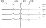
도 10은 와이어 교차부(10000)를 도시한다. 교차부(10000)는 3개의 와이어(10102, 10104, 10106)의 제 1 그룹과 3개의 와이어(10202, 10204, 10206)의 제 2 그룹 사이의 교차를 포함할 수도 있다. 몇몇 실시예에서, 교차부(10000)는 3개의 와이어의 그룹들 중 하나가 하나 이상의 관계 없는 와이어를 포함할 때, 예컨대, 오히려 희망 와이어 패턴이 하나의 와이어 쌍과 하나의 3-와이어 그룹 사이의 교차를 포함하는 경우에 활용될 수 있다. 몇몇 대안적인 실시예에서, 교차부(10000)는 두 3-와이어 그룹 모두가 하나 이상의 관계 없는 와이어를 포함하는 경우, 예컨대, 희망 와이어 패턴이 오히려 두 와이어 쌍 사이의 교차를 포함하고 하나의 와이어는 각각의 3-와이어 그룹 내에 내장되거나 또는 "숨겨져야" 하는 경우에 활용될 수 있다. 도 10에 도시된 바와 같이, 제 1 와이어 그룹의 제 1 와이어(10102)는 제 2 와이어 그룹의 제 2 와이어(10204) 및 제 2 와이어 그룹의 제 3 와이어(10206)의 제 2 측면과 교차하도록(예컨대, 그 아래로 교차함) 구성될 수 있으며, 제 1 와이어 그룹의 제 1 와이어(10102)는 제 2 와이어 그룹의 제 1 와이어(10202)의 제 1 측면과 교차하도록(예컨대, 그 위로 교차함) 구성될 수도 있다. 또한, 제 1 와이어 그룹의 제 2 와이어(10104)는 제 2 와이어 그룹의 제 2 와이어(10204) 및 제 2 와이어 그룹의 제 3 와이어(10206)의 제 2 측면과 교차하도록(예컨대, 그 아래로 교차함) 구성될 수 있으며, 제 1 와이어 그룹의 제 2 와이어(10104)는 제 2 와이어 그룹의 제 1 와이어(10202)의 제 1 측면과 교차하도록(예컨대, 그 위로 교차함) 구성될 수도 있다. 나아가, 제 1 와이어 그룹의 제 3 와이어(10106)는 제 2 와이어 그룹의 각 와이어(10202, 10204, 10206)의 제 1 측면과 교차하도록(예컨대, 그 위로 교차함) 구성될 수도 있다. 교차부(8000 및 9000)와 마찬가지로, 교차부(10000)는 하나 이상의 관계 없는 와이어의 존재로 인한 장치 프로파일의 확대를 최소화하거나 방지하면서도 내부의 와이어가 힌지로서 기능할 수 있게 한다.10 shows a
도 11a와 도 11b, 도 12a와 도 12b, 및 도 13a와 도 13b는 각각 예시적인 관강내 장치의 와이어 그룹에 대한 예시적인 와이어 편조 패턴(11000, 12000 및 13000)을 도시한다. 몇몇 실시예에서, 와이어 편조 패턴(11000, 12000 및 13000)은 다수의 와이어 그룹을 포함할 수 있는 메쉬형 또는 스텐트형 구조체(예컨대, 응괴 결합 구성요소(1300, 4300, 6300 및 7300)) 내의 와이어 그룹에 대해 활용될 수도 있다. 와이어 편조 패턴(11000, 12000 및 13000)은 와이어 그룹 내의 하나 이상의 관계 없는 와이어가 메쉬형 또는 스텐트형 구조체의 와이어 패턴 내에, 특히 와이어 교차부들 사이의 와이어 패턴의 부분들 내에(즉, 와이어 교차부(5000)와 같이 와이어 그룹들이 교차하는 와이어 패턴의 부분들 사이에) 내장되거나 "숨겨지는" 것을 허용할 수 있다. 몇몇 실시예에서, 와이어 편조 패턴(11000, 12000 및 13000)은 와이어 그룹 내의 하나 이상의 관계 없는 와이어를 내장하거나 "숨겨서" 메쉬 세그먼트의 희망 와이어 패턴을 얻기 위해 하나 이상의 와이어 교차부(8000, 9000 및 10000) 사이의 메쉬 세그먼트에서 활용될 수도 있다.11A and 11B, 12A and 12B, and 13A and 13B illustrate exemplary
도 11a 및 도 11b에 도시된 바와 같이, 와이어 편조 패턴(11000)은 와이어(11102, 11104 및 11106)를 포함할 수 있는 제 1 와이어 그룹의 꼬임을 포함한다. 몇몇 실시예에서, "꼬임(twist)"이란 용어는 와이어들이 연속적인 방식으로 다른 와이어 주위에 감겨진 구조를 지칭할 수도 있다. 즉, 와이어(11102)가 다른 두 와이어 주위에 감기고, 와이어(11104), 그리고 이어서 와이어(11106)가 뒤따를 수 있으며, 그 후 와이어(11102)가 다시 다른 두 와이어 주위에 감길 수 있다. 패턴(11000)의 꼬임으로 인해, 3개의 와이어(11102, 11104, 11106) 모두가 우발적인 축방향 이동 또는 슬라이딩에 대해 함께 고정될 수도 있다. 몇몇 실시예에서, 패턴(11000)은 1개 또는 2개의 관계 없는 와이어를 갖는 와이어 그룹에서 활용될 수도 있다. 위에서 설명한 바와 같이, 와이어(11102, 11104 및 11106)는 와이어(11102, 11104 및 11106)가 다른 와이어 그룹과 교차하지 않는 메쉬 세그먼트의 일부에서(즉, 제 1 와이어 그룹과 다른 와이어 그룹의 인접한 두 교차부 사이) 패턴(11000)으로 꼬일 수도 있다.11A and 11B, the
도 12a 및 도 12b에 도시된 바와 같이, 와이어 편조 패턴(12000)은 제 1 그룹의 3개의 와이어(12102, 12104, 12106)를 포함한다. 도 12a에 도시된 바와 같이, 와이어(12104, 12106)는 와이어(12104, 12106)가 서로를 감싸는 꼬임 구조를 형성하도록 함께 꼬일 수 있다. 와이어(12104, 12106)는 와이어(12102, 12104, 12106)가 다른 와이어 그룹과 교차하지 않는 메쉬 세그먼트의 일부에서(즉, 제 1 와이어 그룹과 다른 와이어 그룹의 인접한 두 교차부 사이에서) 꼬임 구조로 꼬일 수도 있다. 그러나, 와이어(12102)는 와이어 편조 패턴(12000)의 꼬임 구조 내에서 와이어(12104) 또는 와이어(12106)와 함께 꼬이지 않을 수도 있다. 유리하게는, 패턴(12000)은 와이어(12104 및 12106)를 우발적인 축방향 이동 또는 슬라이딩에 대해 함께 고정할 수 있는 반면에, 와이어(12102)는 방해 없이 축방향으로 자유롭게 이동하도록 남겨둘 수도 있다. 나아가, 와이어 편조 패턴(12000)은 또한 패턴(12000) 내의 어떠한 소정 지점에서도 2개 이하의 와이어가 접촉하기 때문에 하나 이상의 관계 없는 와이어의 존재로 인해 관강내 장치의 프로파일이 확대되는 것을 방지할 수 있다. 몇몇 실시예에서, 패턴(12000)은 하나 이상의 관계 없는 와이어(예컨대, 와이어(12102, 12104, 또는 12106) 중 하나 이상)를 갖는 와이어 그룹에서 활용될 수 있다.12A and 12B, the
도 13a 및 도 13b에 도시된 바와 같이, 와이어 편조 패턴(13000)은 제 1 그룹의 3개의 와이어(13102, 13104, 13106)로 된 편조 패턴을 포함한다. 와이어 편조 패턴(13000)은 와이어(13102, 13104, 13106)의 인터로킹 메이폴 구조(interlocking maypole structure)를 포함할 수도 있다. 도 13a에 도시된 바와 같이, 인터로킹 메이폴 구조 내에서, 제 1 와이어(13102)는 제 2 와이어(13104)의 제 2 측면과 교차하도록(예컨대, 그 아래로 교차함) 구성될 수도 있다. 또한, 제 1 와이어(13102)는 제 3 와이어(13106)의 제 1 측면과 교차하도록(예컨대, 그 위로 교차함) 구성될 수도 있다. 그러나, 제 2 와이어(13104) 및 제 3 와이어(13106)는 패턴(13000)의 인터로킹 메이폴 구조에서 서로 접촉하거나 교차하지 않는다. 패턴(13000)의 인터로킹 메이폴 구조는 와이어(13102, 13104, 13106)가 다른 와이어 그룹과 교차하지 않는 메쉬 세그먼트의 일부에(즉, 제 1 와이어 그룹과 다른 와이어 그룹의 인접한 두 교차부 사이에) 형성될 수 있다. 유리하게는, 패턴(13000)은 와이어(13102, 13104 및 13106)를 서로에 대한 축방향 이동 또는 슬라이딩에 대해 고정할 수 있으며, 또한 패턴(13000) 내의 어떠한 소정 지점에서도 2개 이하의 와이어가 접촉하기 때문에 하니 이상의 관계 없는 와이어의 존재로 인해 관강내 장치의 프로파일이 확대되는 것을 방지할 수도 있다. 몇몇 실시예에서, 패턴(13000)은 하나 이상의 관계 없는 와이어(예컨대, 와이어(13102), 와이어(13104) 및/또는 와이어(13106))를 갖는 와이어 그룹에서 활용될 수 있다.13A and 13B, the
전술한 설명은 예시의 목적으로 제공되었다. 이는 완전하지 않으며 개시된 바로 그 형태 또는 실시예에 한정되지 않는다. 실시예들의 수정예 및 개조예는 개시된 실시예들의 세부사항 및 실시를 고려함으로써 명백해질 것이다. 특정 구성요소들이 서로 결합되는 것으로 설명되었지만, 이러한 구성요소들은 임의의 적절한 방식으로 서로 통합되거나 구분될 수도 있다.The foregoing description has been provided for purposes of illustration. This is not exhaustive and is not limited to the exact form or embodiment disclosed. Modifications and adaptations of the embodiments will become apparent by considering the details and implementation of the disclosed embodiments. Although certain components have been described as being coupled to each other, these components may be integrated or separated from each other in any suitable manner.
나아가, 예시적인 실시예가 본 명세서에 설명되었지만, 그 범위는 본 개시에 기초한 균등 요소, 수정예, 생략예, (예컨대, 다양한 실시예에 걸친 태양의) 조합, 개조예 및/또는 변경예를 갖는 임의의 및 모든 실시예를 포함한다. 청구범위의 요소는 청구범위에 사용된 언어에 기초하여 넓게 해석되어야 하고, 본 명세서에 또는 본원의 심사 과정 중에 설명된 예에 한정되지 않으며, 이러한 예는 비배타적인 것으로 해석되어야 한다. 또한, 개시된 방법의 단계들은 단계의 재배치 및/또는 단계의 삽입 또는 삭제를 포함하여 임의의 방식으로 수정될 수 있다.Furthermore, although exemplary embodiments have been described herein, the scope is limited to having equivalent elements, modifications, omissions, combinations (e.g., aspects over various embodiments), adaptations, and/or variations based on the present disclosure. Include any and all examples. Elements of the claims are to be construed broadly based on the language used in the claims, and are not limited to the examples described herein or during the review process herein, and such examples are to be construed as non-exclusive. In addition, the steps of the disclosed method may be modified in any manner, including rearrangement of steps and/or insertion or deletion of steps.
본 개시의 특징 및 이점은 상세한 설명으로부터 명백하며, 따라서 첨부된 청구범위는 본 개시의 진정한 사상 및 범위 내에 속하는 모든 시스템 및 방법을 포괄하는 것으로 의도된다. 본 명세서에서 사용된 바와 같이, 부정관사 "a" 및 "an"은 "하나 이상"을 의미한다. 마찬가지로, 복수 용어의 사용은 주어진 문맥에서 명확한 것이 아닌 한 반드시 복수를 의미하지는 않는다. "및" 또는 "또는"과 같은 단어는 특별히 달리 지시하지 않는 한 "및/또는"을 의미한다. 또한, 본 개시를 연구함으로써 수많은 수정예 및 변경예가 쉽게 발생할 수 있기 때문에, 본 개시를 예시되고 설명된 정확한 구성 및 동작에 한정하는 것은 바람직하지 않으며, 그에 따라서 모든 적절한 수정예 및 균등물이 본 개시의 범위에 속할 수 있다.Features and advantages of the present disclosure are apparent from the detailed description, and thus the appended claims are intended to cover all systems and methods falling within the true spirit and scope of this disclosure. As used herein, the indefinite articles “a” and “an” mean “one or more”. Likewise, the use of plural terms does not necessarily mean plural unless it is clear in a given context. Words such as "and" or "or" mean "and/or" unless specifically indicated otherwise. In addition, since numerous modifications and alterations can easily occur by studying the present disclosure, it is not desirable to limit the present disclosure to the exact configuration and operation illustrated and described, and all suitable modifications and equivalents are thus disclosed herein. It can belong to the scope of.
본 명세서에 개시된 실시예의 세부사항 및 실시를 고려하면 다른 실시예가 명백해질 것이다. 세부사항 및 실시예는 단지 예로서 고려할 의도이며, 개시된 실시예의 진정한 범위 및 정신은 하기의 청구범위에 의해 표시된다.Other embodiments will become apparent upon consideration of the details and implementation of the embodiments disclosed herein. The details and examples are intended to be considered by way of example only, and the true scope and spirit of the disclosed embodiments are indicated by the following claims.
Claims (51)
상기 복수의 와이어가 제 1 케이블을 형성하도록 꼬여 있는 제 1 영역;
상기 복수의 와이어가 혈액 응괴(blood clot)를 포착하도록 구성된 확장 가능한 메쉬 세그먼트(expandable mesh segment)를 형성하도록 직조되어 있는, 상기 제 1 영역에 대해 원위에 있는 제 2 영역; 및
상기 제 2 영역에 대해 원위에 있으며 상기 세장형 몸체의 원위 팁(distal tip)을 형성하는 제 3 영역― 상기 제 3 영역에서의 상기 복수의 와이어는 제 2 케이블을 형성하도록 꼬여 있음 ―을 포함하고,
상기 복수의 와이어 중 적어도 하나의 와이어는 상기 제 1 영역으로부터 상기 세장형 몸체의 원위 팁까지 연속적으로 연장되는
관강내 장치.In an intraluminal device comprising an elongated body formed of a plurality of wires,
A first region in which the plurality of wires are twisted to form a first cable;
A second region distal to the first region, wherein the plurality of wires are woven to form an expandable mesh segment configured to capture blood clots; And
A third region distal to the second region and forming a distal tip of the elongate body, wherein the plurality of wires in the third region are twisted to form a second cable, and ,
At least one wire of the plurality of wires continuously extends from the first region to the distal tip of the elongate body.
Intraluminal device.
상기 확장 가능한 메쉬 세그먼트는,
상기 복수의 와이어가 제 1 직조 패턴(weave pattern)을 형성하도록 직조되어 있는 적어도 하나의 확장 가능한 필터 세그먼트― 상기 제 1 직조 패턴의 내부에는 2개 이상의 와이어 사이에 개구가 형성되어 있음 ―; 및
상기 복수의 와이어가 제 2 직조 패턴을 형성하도록 직조되어 있는 적어도 하나의 확장 가능한 응괴 포착 구역(expandable clot capture zone)― 상기 제 2 직조 패턴은 상기 제 1 직조 패턴과 상이하며, 상기 제 2 직조 패턴의 내부에는 2개 이상의 와이어 사이에 개구가 형성되어 있음 ―을 포함하고,
확장된 구성(expanded configuration)에서, 상기 적어도 하나의 응괴 포착 구역의 개구는 상기 적어도 하나의 필터 세그먼트의 개구보다 더 큰
관강내 장치.The method of claim 1,
The expandable mesh segment,
At least one expandable filter segment in which the plurality of wires are woven to form a first weave pattern, wherein an opening is formed between two or more wires within the first woven pattern; And
At least one expandable clot capture zone in which the plurality of wires are woven to form a second woven pattern-the second woven pattern is different from the first woven pattern, and the second woven pattern Including an opening is formed between two or more wires in the inside of,
In the expanded configuration, the opening of the at least one clot trapping zone is larger than the opening of the at least one filter segment.
Intraluminal device.
상기 적어도 하나의 응괴 포착 구역에서의 상기 복수의 와이어는 상기 적어도 하나의 응괴 포착 구역 내의 복수의 와이어 그룹으로 그룹화되고, 상기 복수의 와이어 그룹의 각 와이어 그룹은 적어도 2개의 와이어를 포함하고, 서로 얽힌 와이어 조합(intertwined wire combination)을 형성하는
관강내 장치.The method of claim 2,
The plurality of wires in the at least one clot trapping zone are grouped into a plurality of wire groups in the at least one clot trapping zone, and each wire group of the plurality of wire groups includes at least two wires, entangled with each other. Forming an intertwined wire combination
Intraluminal device.
상기 적어도 하나의 응괴 포착 구역의 개구는 상기 서로 얽힌 와이어 조합 중 적어도 2개 사이에 형성되는
관강내 장치.The method of claim 3,
The opening of the at least one clot trapping zone is formed between at least two of the entangled wire combinations.
Intraluminal device.
상기 복수의 와이어 그룹의 각 와이어 그룹은 1개의 와이어, 2개의 와이어, 3개의 와이어 또는 4개의 와이어를 포함하는
관강내 장치.The method of claim 3,
Each wire group of the plurality of wire groups includes one wire, two wires, three wires, or four wires.
Intraluminal device.
상기 적어도 하나의 확장 가능한 필터 세그먼트는 상기 적어도 하나의 확장 가능한 응괴 포착 구역보다 더 작은 응괴를 포착하도록 구성되는
관강내 장치.The method of claim 2,
The at least one expandable filter segment is configured to capture a clot smaller than the at least one expandable clot capture zone.
Intraluminal device.
상기 확장 가능한 메쉬 세그먼트는,
제 1 필터 세그먼트;
상기 제 1 필터 세그먼트에 대해 원위에 있는 제 2 필터 세그먼트;
상기 관강내 장치의 상기 제 1 영역과 상기 제 1 필터 세그먼트 사이에 위치되는 제 1 응괴 포착 구역; 및
상기 관강내 장치의 상기 제 3 영역과 상기 제 2 필터 세그먼트 사이에 위치되는 제 2 응괴 포착 구역을 포함하는
관강내 장치.The method of claim 2,
The expandable mesh segment,
A first filter segment;
A second filter segment distal to the first filter segment;
A first agglomerate trapping zone located between the first region of the intraluminal device and the first filter segment; And
And a second clot trapping zone located between the third region of the intraluminal device and the second filter segment.
Intraluminal device.
상기 복수의 와이어는 8개 와이어의 세트, 10개 와이어의 세트 및 12개 와이어의 세트 중 적어도 하나로 구성되는
관강내 장치.The method of claim 1,
The plurality of wires is composed of at least one of a set of 8 wires, a set of 10 wires, and a set of 12 wires.
Intraluminal device.
상기 적어도 하나의 와이어는 40 마이크론 내지 200 마이크론의 직경을 갖는
관강내 장치.The method of claim 1,
The at least one wire has a diameter of 40 microns to 200 microns
Intraluminal device.
상기 적어도 하나의 와이어는 50 마이크론 내지 75 마이크론의 직경을 갖는
관강내 장치.The method of claim 9,
The at least one wire has a diameter of 50 microns to 75 microns
Intraluminal device.
상기 세장형 몸체를 따르는 지점에 위치된 적어도 하나의 방사선 불투과성 마커(radiopaque marker)를 추가로 포함하고, 상기 세장형 몸체를 따르는 지점은 상기 제 2 영역에 대해 원위에 있는 지점 및 상기 제 2 영역의 근위에 있는 지점 중 적어도 하나인
관강내 장치.The method of claim 1,
Further comprising at least one radiopaque marker located at a point along the elongate body, wherein a point along the elongate body is a point distal to the second region and the second region At least one of the proximal points of
Intraluminal device.
상기 관강내 장치의 제 1 영역, 상기 관강내 장치의 제 2 영역, 및 상기 관강내 장치의 제 3 영역은 하나의 단일 구조로 형성되는
관강내 장치.The method of claim 1,
The first region of the intraluminal device, the second region of the intraluminal device, and the third region of the intraluminal device are formed as a single structure.
Intraluminal device.
상기 세장형 몸체의 제 1 케이블을 형성하기 위해 맨드릴(mandrel)의 제 1 세그먼트 상에서 복수의 와이어를 꼬는 것;
혈액 응괴를 포착하도록 구성된 상기 세장형 몸체의 확장 가능한 메쉬 세그먼트를 형성하기 위해 상기 맨드릴의 제 2 세그먼트 상에서 상기 복수의 와이어를 직조하는 것; 및
상기 세장형 몸체의 제 2 케이블을 형성하기 위해 상기 맨드릴의 제 3 세그먼트 상에서 상기 복수의 와이어를 꼬는 것을 포함하고,
상기 맨드릴의 제 2 세그먼트는 상기 맨드릴의 제 1 세그먼트와 상기 맨드릴의 제 3 세그먼트 사이에 위치되는
관강내 장치 제조 방법.In the method of manufacturing an intraluminal device comprising an elongate body formed of a plurality of wires,
Twisting a plurality of wires on a first segment of a mandrel to form a first cable of the elongate body;
Weaving the plurality of wires on a second segment of the mandrel to form an expandable mesh segment of the elongate body configured to capture blood clots; And
Twisting the plurality of wires on a third segment of the mandrel to form a second cable of the elongate body,
The second segment of the mandrel is located between the first segment of the mandrel and the third segment of the mandrel
Intraluminal device manufacturing method.
상기 확장 가능한 메쉬 세그먼트를 열처리하는 것을 추가로 포함하는
관강내 장치 제조 방법.The method of claim 13,
Further comprising heat-treating the expandable mesh segment
Intraluminal device manufacturing method.
상기 맨드릴의 제 2 세그먼트는 상기 맨드릴의 제 1 세그먼트 및 상기 맨드릴의 제 3 세그먼트보다 더 큰 직경을 갖는
관강내 장치 제조 방법.The method of claim 13,
The second segment of the mandrel has a larger diameter than the first segment of the mandrel and the third segment of the mandrel
Intraluminal device manufacturing method.
상기 복수의 와이어는 8개 와이어의 세트, 10개 와이어의 세트 및 12개 와이어의 세트 중 적어도 하나로 구성되는
관강내 장치 제조 방법.The method of claim 13,
The plurality of wires is composed of at least one of a set of 8 wires, a set of 10 wires, and a set of 12 wires.
Intraluminal device manufacturing method.
상기 복수의 와이어 중 적어도 하나의 와이어는 40 마이크론 내지 200 마이크론의 직경을 갖는
관강내 장치 제조 방법.The method of claim 13,
At least one of the plurality of wires has a diameter of 40 microns to 200 microns
Intraluminal device manufacturing method.
상기 복수의 와이어 중 적어도 하나의 와이어는 50 마이크론 내지 75 마이크론의 직경을 갖는
관강내 장치 제조 방법.The method of claim 17,
At least one of the plurality of wires has a diameter of 50 microns to 75 microns
Intraluminal device manufacturing method.
상기 세장형 몸체의 제 1 케이블, 상기 세장형 몸체의 확장 가능한 메쉬 세그먼트, 및 상기 세장형 몸체의 제 2 케이블은 하나의 단일 구조로 형성되는
관강내 장치 제조 방법.The method of claim 13,
The first cable of the elongate body, the expandable mesh segment of the elongate body, and the second cable of the elongate body are formed in one single structure.
Intraluminal device manufacturing method.
상기 복수의 와이어가 제 1 케이블을 형성하도록 꼬여 있는 제 1 영역;
상기 복수의 와이어가 혈액 응괴를 포착하도록 구성된 확장 가능한 메쉬 세그먼트를 형성하도록 직조되어 있는, 상기 제 1 영역에 대해 원위에 있는 제 2 영역; 및
상기 제 2 영역에 대해 원위에 있으며 상기 세장형 몸체의 원위 팁을 형성하는 제 3 영역― 상기 제 3 영역에서의 상기 복수의 와이어는 제 2 케이블을 형성하도록 꼬여 있음 ―을 포함하고,
상기 제 2 케이블은 상기 제 1 케이블보다 더 유연하도록 구성되는
관강내 장치.In the lumen device comprising an elongate body formed of a plurality of wires,
A first region in which the plurality of wires are twisted to form a first cable;
A second region distal to the first region, wherein the plurality of wires are woven to form an expandable mesh segment configured to capture blood clots; And
A third region distal to the second region and forming a distal tip of the elongate body, wherein the plurality of wires in the third region are twisted to form a second cable,
The second cable is configured to be more flexible than the first cable
Intraluminal device.
상기 복수의 와이어 중 적어도 하나의 와이어는 40 마이크론 내지 200 마이크론의 직경을 갖는
관강내 장치.The method of claim 20,
At least one of the plurality of wires has a diameter of 40 microns to 200 microns
Intraluminal device.
상기 복수의 와이어 중 적어도 하나의 와이어는 50 마이크론 내지 75 마이크론의 직경을 갖는
관강내 장치.The method of claim 21,
At least one of the plurality of wires has a diameter of 50 microns to 75 microns
Intraluminal device.
상기 제 2 케이블은 상기 제 1 케이블보다 더 작은 케이블 권취 각도(cable coiling angle)를 갖도록 구성되는
관강내 장치.The method of claim 20,
The second cable is configured to have a smaller cable coiling angle than the first cable.
Intraluminal device.
상기 제 2 케이블은 상기 제 1 케이블보다 더 적은 수의 와이어를 포함하는
관강내 장치.The method of claim 20,
The second cable comprises fewer wires than the first cable.
Intraluminal device.
상기 제 2 케이블은 내부에 있는 상기 복수의 와이어의 부분들의 직경을 감소시키도록 처리되는
관강내 장치.The method of claim 20,
The second cable is treated to reduce the diameter of portions of the plurality of wires therein.
Intraluminal device.
상기 복수의 와이어가 제 1 케이블을 형성하도록 꼬여 있는 제 1 영역;
상기 복수의 와이어가 확장 가능한 메쉬 세그먼트를 형성하도록 직조되어 있는, 상기 제 1 영역에 대해 원위에 있는 제 2 영역; 및
상기 상기 제 2 영역에 대해 원위에 있으며 상기 세장형 몸체의 원위 팁을 형성하는 제 3 영역― 상기 제 3 영역에서의 상기 복수의 와이어는 제 2 케이블을 형성하도록 꼬여 있음 ―을 포함하고,
상기 확장 가능한 메쉬 세그먼트에서의 상기 복수의 와이어는 상기 확장 가능한 메쉬 세그먼트 내의 복수의 와이어 쌍으로 그룹화되고, 상기 복수의 와이어 쌍의 각 와이어 쌍은 서로 얽힌 와이어 조합을 형성하고,
상기 복수의 와이어 쌍 중 적어도 제 1 와이어 쌍 및 상기 복수의 와이어 쌍 중 적어도 제 2 와이어 쌍은 상기 확장 가능한 메쉬 세그먼트 내에 교차부(crossing)를 형성하고, 상기 제 1 와이어 쌍의 적어도 하나의 와이어는 상기 교차부에서 상기 제 2 와이어 쌍의 각 와이어 사이를 통과하는
관강내 장치.In the lumen device comprising an elongate body formed of a plurality of wires,
A first region in which the plurality of wires are twisted to form a first cable;
A second region distal to the first region, wherein the plurality of wires are woven to form an expandable mesh segment; And
A third region distal to the second region and forming a distal tip of the elongate body, wherein the plurality of wires in the third region are twisted to form a second cable,
The plurality of wires in the expandable mesh segment are grouped into a plurality of wire pairs in the expandable mesh segment, each wire pair of the plurality of wire pairs form a wire combination entangled with each other,
At least a first wire pair of the plurality of wire pairs and at least a second wire pair of the plurality of wire pairs form a crossing in the expandable mesh segment, and at least one wire of the first wire pair is Passing between each wire of the second wire pair at the intersection
Intraluminal device.
상기 복수의 와이어 쌍의 상기 제 1 와이어 쌍은 상기 교차부의 근위에 적어도 제 1 쌍 꼬임(pairwise twist)을 포함하고, 상기 교차부의 원위에 적어도 제 2 쌍 꼬임을 포함하는
관강내 장치.The method of claim 26,
The first wire pair of the plurality of wire pairs comprises at least a first pairwise twist proximal to the intersection, and at least a second pair twist distal to the intersection.
Intraluminal device.
상기 제 2 와이어 쌍의 적어도 하나의 와이어는 상기 교차부에서 상기 제 1 와이어 쌍의 각 와이어 사이를 통과하는
관강내 장치.The method of claim 26,
At least one wire of the second wire pair passes between each wire of the first wire pair at the intersection
Intraluminal device.
상기 제 1 와이어 쌍의 적어도 하나의 와이어는 상기 교차부에서 상기 제 2 와이어 쌍의 와이어들 사이를 통과하지 않는
관강내 장치.The method of claim 26,
At least one wire of the first wire pair does not pass between the wires of the second wire pair at the intersection.
Intraluminal device.
상기 제 2 와이어 쌍의 적어도 하나의 와이어는 상기 교차부에서 상기 제 1 와이어 쌍의 와이어들 사이를 통과하지 않는
관강내 장치.The method of claim 26,
At least one wire of the second wire pair does not pass between the wires of the first wire pair at the intersection.
Intraluminal device.
상기 복수의 와이어가 제 1 케이블을 형성하도록 꼬여 있는 제 1 영역;
상기 복수의 와이어가 혈액 응괴를 포착하도록 구성된 확장 가능한 메쉬 세그먼트를 형성하도록 직조되어 있는, 상기 제 1 영역에 대해 원위에 있는 제 2 영역; 및
상기 제 2 영역에 대해 원위에 있으며 상기 세장형 몸체의 원위 팁을 형성하는 제 3 영역― 상기 제 3 영역에서의 상기 복수의 와이어는 제 2 케이블을 형성하도록 꼬여 있음 ―을 포함하고,
상기 제 1 영역은 상기 제 2 영역 및 상기 제 3 영역 중 하나 이상보다 더 많은 와이어로 구성되는
관강내 장치.In the lumen device comprising an elongate body formed of a plurality of wires,
A first region in which the plurality of wires are twisted to form a first cable;
A second region distal to the first region, wherein the plurality of wires are woven to form an expandable mesh segment configured to capture blood clots; And
A third region distal to the second region and forming a distal tip of the elongate body, wherein the plurality of wires in the third region are twisted to form a second cable,
The first region is composed of more wires than at least one of the second region and the third region
Intraluminal device.
상기 제 2 영역은 상기 제 3 영역과 동일한 개수의 와이어로 구성되는
관강내 장치.The method of claim 31,
The second region is composed of the same number of wires as the third region.
Intraluminal device.
상기 제 2 영역은 상기 제 3 영역보다 더 많은 와이어로 구성되는
관강내 장치.The method of claim 31,
The second region is composed of more wires than the third region
Intraluminal device.
상기 제 1 영역은 11개의 와이어를 포함하고, 상기 제 2 영역은 8개의 와이어를 포함하고, 상기 제 3 영역은 8개의 와이어를 포함하는
관강내 장치.The method of claim 31,
The first area includes 11 wires, the second area includes 8 wires, and the third area includes 8 wires.
Intraluminal device.
상기 제 1 영역은 12개의 와이어를 포함하고, 상기 제 2 영역은 8개의 와이어를 포함하고, 상기 제 3 영역은 8개의 와이어를 포함하는
관강내 장치.The method of claim 31,
The first area includes 12 wires, the second area includes 8 wires, and the third area includes 8 wires.
Intraluminal device.
상기 복수의 와이어 중 적어도 하나의 와이어는 상기 제 1 영역으로부터 상기 제 3 영역까지 연속적으로 연장되는
관강내 장치.The method of claim 31,
At least one wire of the plurality of wires continuously extends from the first region to the third region.
Intraluminal device.
상기 관강내 장치의 제 1 영역, 상기 관강내 장치의 제 2 영역, 및 상기 관강내 장치의 제 3 영역은 하나의 단일 구조로 형성되는
관강내 장치.The method of claim 31,
The first region of the intraluminal device, the second region of the intraluminal device, and the third region of the intraluminal device are formed as a single structure.
Intraluminal device.
상기 세장형 몸체의 제 1 케이블을 형성하기 위해 맨드릴의 제 1 세그먼트 상에서 복수의 와이어를 꼬는 것;
상기 제 1 케이블의 원위 단부에서 상기 복수의 와이어 중 적어도 하나의 와이어를 절단하는 것;
혈액 응괴를 포착하도록 구성된 상기 세장형 몸체의 확장 가능한 메쉬 세그먼트를 형성하기 위해 상기 맨드릴의 제 2 세그먼트 상에 상기 복수의 와이어의 나머지 와이어를 직조하는 것; 및
상기 세장형 몸체의 제 2 케이블을 형성하기 위해 상기 맨드릴의 제 3 세그먼트 상에서 상기 복수의 와이어의 나머지 와이어를 꼬는 것을 포함하고,
상기 맨드릴의 제 2 세그먼트는 상기 맨드릴의 제 1 세그먼트와 상기 맨드릴의 제 3 세그먼트 사이에 위치되는
관강내 장치 제조 방법.In the method of manufacturing an intraluminal device comprising an elongate body formed of a plurality of wires,
Twisting a plurality of wires on a first segment of a mandrel to form a first cable of the elongate body;
Cutting at least one of the plurality of wires at the distal end of the first cable;
Weaving the remaining wires of the plurality of wires onto the second segment of the mandrel to form an expandable mesh segment of the elongate body configured to capture blood clots; And
Twisting the remaining wires of the plurality of wires on a third segment of the mandrel to form a second cable of the elongate body,
The second segment of the mandrel is located between the first segment of the mandrel and the third segment of the mandrel
Intraluminal device manufacturing method.
상기 확장 가능한 메쉬 세그먼트의 원위 단부에서 상기 복수의 와이어 중 적어도 하나의 와이어를 절단하는 것을 추가로 포함하는
관강내 장치 제조 방법.The method of claim 38,
Further comprising cutting at least one wire of the plurality of wires at the distal end of the expandable mesh segment.
Intraluminal device manufacturing method.
상기 확장 가능한 메쉬 세그먼트를 열처리하는 것을 추가로 포함하는
관강내 장치 제조 방법.The method of claim 38,
Further comprising heat-treating the expandable mesh segment
Intraluminal device manufacturing method.
상기 맨드릴의 제 2 세그먼트는 상기 맨드릴의 제 1 세그먼트 및 상기 맨드릴의 제 3 세그먼트보다 더 큰 직경을 갖는
관강내 장치 제조 방법.The method of claim 38,
The second segment of the mandrel has a larger diameter than the first segment of the mandrel and the third segment of the mandrel
Intraluminal device manufacturing method.
상기 복수의 와이어는 8개의 와이어, 10개의 와이어 또는 12개의 와이어로 구성되는
관강내 장치 제조 방법.The method of claim 38,
The plurality of wires are composed of 8 wires, 10 wires or 12 wires.
Intraluminal device manufacturing method.
상기 복수의 와이어 중 적어도 하나의 와이어는 40 마이크론 내지 200 마이크론의 직경을 갖는
관강내 장치 제조 방법.The method of claim 38,
At least one of the plurality of wires has a diameter of 40 microns to 200 microns
Intraluminal device manufacturing method.
상기 복수의 와이어 중 적어도 하나의 와이어는 50 마이크론 내지 75 마이크론의 직경을 갖는
관강내 장치 제조 방법.The method of claim 43,
At least one of the plurality of wires has a diameter of 50 microns to 75 microns
Intraluminal device manufacturing method.
상기 세장형 몸체의 제 1 케이블, 상기 세장형 몸체의 확장 가능한 메쉬 세그먼트, 및 상기 세장형 몸체의 제 2 케이블은 하나의 단일 구조로 형성되는
관강내 장치 제조 방법.The method of claim 38,
The first cable of the elongate body, the expandable mesh segment of the elongate body, and the second cable of the elongate body are formed in one single structure.
Intraluminal device manufacturing method.
상기 복수의 와이어가 제 1 케이블을 형성하도록 꼬여 있는 제 1 영역;
상기 복수의 와이어가 확장 가능한 메쉬 세그먼트를 형성하도록 직조되어 있는, 상기 제 1 영역에 대해 원위에 있는 제 2 영역; 및
상기 제 2 영역에 대해 원위에 있으며 상기 세장형 몸체의 원위 팁을 형성하는 제 3 영역― 상기 제 3 영역에서의 상기 복수의 와이어는 제 2 케이블을 형성하도록 꼬여 있음 ―을 포함하고,
상기 확장 가능한 메쉬 세그먼트에서의 상기 복수의 와이어는 제 1 와이어 그룹 및 제 2 와이어 그룹을 포함하고, 상기 제 1 와이어 그룹은 2개의 와이어를 포함하며 상기 제 2 와이어 그룹은 3개의 와이어를 포함하고, 상기 복수의 와이어의 각 와이어는 제 1 측면 및 상기 제 1 측면의 반대편의 제 2 측면을 포함하고,
상기 제 1 와이어 그룹의 제 1 와이어는 상기 제 2 와이어 그룹의 제 1 와이어 및 상기 제 2 와이어 그룹의 제 2 와이어 둘 모두의 제 1 측면과 교차하도록 구성되고, 상기 제 1 와이어 그룹의 제 1 와이어는 상기 제 2 와이어 그룹의 제 3 와이어의 제 2 측면과 교차하도록 구성되고,
상기 제 1 와이어 그룹의 제 2 와이어는 상기 제 2 와이어 그룹의 제 1 와이어 및 상기 제 2 와이어 그룹의 제 2 와이어 둘 모두의 제 2 측면과 교차하도록 구성되고, 상기 제 1 와이어 그룹의 제 2 와이어는 상기 제 2 와이어 그룹의 제 3 와이어의 제 1 측면과 교차하도록 구성되는
관강내 장치.In the lumen device comprising an elongate body formed of a plurality of wires,
A first region in which the plurality of wires are twisted to form a first cable;
A second region distal to the first region, wherein the plurality of wires are woven to form an expandable mesh segment; And
A third region distal to the second region and forming a distal tip of the elongate body, wherein the plurality of wires in the third region are twisted to form a second cable,
The plurality of wires in the expandable mesh segment comprises a first wire group and a second wire group, the first wire group comprises two wires and the second wire group comprises three wires, Each wire of the plurality of wires includes a first side and a second side opposite to the first side,
The first wire of the first wire group is configured to intersect a first side of both the first wire of the second wire group and the second wire of the second wire group, and the first wire of the first wire group Is configured to intersect with the second side of the third wire of the second wire group,
The second wire of the first wire group is configured to intersect a second side of both the first wire of the second wire group and the second wire of the second wire group, and the second wire of the first wire group Is configured to intersect with the first side of the third wire of the second wire group
Intraluminal device.
상기 복수의 와이어가 제 1 케이블을 형성하도록 꼬여 있는 제 1 영역;
상기 복수의 와이어가 확장 가능한 메쉬 세그먼트를 형성하도록 직조되어 있는, 상기 제 1 영역에 대해 원위에 있는 제 2 영역; 및
상기 제 2 영역에 대해 원위에 있으며 상기 세장형 몸체의 원위 팁을 형성하는 제 3 영역― 상기 제 3 영역에서의 상기 복수의 와이어는 제 2 케이블을 형성하도록 꼬여 있음 ―을 포함하고,
상기 확장 가능한 메쉬 세그먼트에서의 상기 복수의 와이어는 제 1 와이어 그룹 및 제 2 와이어 그룹을 포함하고, 상기 제 1 와이어 그룹은 2개의 와이어를 포함하며 상기 제 2 와이어 그룹은 3개의 와이어를 포함하고, 상기 복수의 와이어의 각 와이어는 제 1 측면 및 상기 제 1 측면의 반대편의 제 2 측면을 포함하고,
상기 제 1 와이어 그룹의 제 1 와이어는 상기 제 2 와이어 그룹의 제 1 와이어의 제 1 측면과 교차하고, 상기 제 2 와이어 그룹의 제 2 와이어 및 상기 제 2 와이어 그룹의 제 3 와이어 둘 모두의 제 2 측면과 교차하도록 구성되고,
상기 제 1 와이어 그룹의 제 2 와이어는 상기 제 2 와이어 그룹의 각 와이어의 제 1 측면과 교차하도록 구성되는
관강내 장치.In the lumen device comprising an elongate body formed of a plurality of wires,
A first region in which the plurality of wires are twisted to form a first cable;
A second region distal to the first region, wherein the plurality of wires are woven to form an expandable mesh segment; And
A third region distal to the second region and forming a distal tip of the elongate body, wherein the plurality of wires in the third region are twisted to form a second cable,
The plurality of wires in the expandable mesh segment comprises a first wire group and a second wire group, the first wire group comprises two wires and the second wire group comprises three wires, Each wire of the plurality of wires includes a first side and a second side opposite to the first side,
The first wire of the first wire group intersects the first side of the first wire of the second wire group, and the second wire of the second wire group and the third wire of the second wire group. 2 is configured to intersect with the side,
The second wire of the first wire group is configured to cross a first side of each wire of the second wire group.
Intraluminal device.
상기 복수의 와이어가 제 1 케이블을 형성하도록 꼬여 있는 제 1 영역;
상기 복수의 와이어가 확장 가능한 메쉬 세그먼트를 형성하도록 직조되어 있는, 상기 제 1 영역에 대해 원위에 있는 제 2 영역; 및
상기 제 2 영역에 대해 원위에 있으며 상기 세장형 몸체의 원위 팁을 형성하는 제 3 영역― 상기 제 3 영역에서의 상기 복수의 와이어는 제 2 케이블을 형성하도록 꼬여 있음 ―을 포함하고,
상기 확장 가능한 메쉬 세그먼트에서의 상기 복수의 와이어는 제 1 와이어 그룹 및 제 2 와이어 그룹을 포함하고, 상기 제 1 와이어 그룹은 3개의 와이어를 포함하며 상기 제 2 와이어 그룹은 3개의 와이어를 포함하고, 상기 복수의 와이어의 각 와이어는 제 1 측면 및 상기 제 1 측면의 반대편의 제 2 측면을 포함하고,
상기 제 1 와이어 그룹의 제 1 와이어는 상기 제 2 와이어 그룹의 제 1 와이어의 제 1 측면과 교차하고, 상기 제 2 와이어 그룹의 제 2 와이어 및 상기 제 2 와이어 그룹의 제 3 와이어 둘 모두의 제 2 측면과 교차하도록 구성되고,
상기 제 1 와이어 그룹의 제 2 와이어는 상기 제 2 와이어 그룹의 제 1 와이어의 제 1 측면과 교차하고, 상기 제 2 와이어 그룹의 제 2 와이어 및 상기 제 2 와이어 그룹의 제 3 와이어 둘 모두의 제 2 측면과 교차하도록 구성되고,
상기 제 1 와이어 그룹의 제 3 와이어는 상기 제 2 와이어 그룹의 각 와이어의 제 1 측면과 교차하도록 구성되는
관강내 장치.In the lumen device comprising an elongate body formed of a plurality of wires,
A first region in which the plurality of wires are twisted to form a first cable;
A second region distal to the first region, wherein the plurality of wires are woven to form an expandable mesh segment; And
A third region distal to the second region and forming a distal tip of the elongate body, wherein the plurality of wires in the third region are twisted to form a second cable,
The plurality of wires in the expandable mesh segment comprises a first wire group and a second wire group, the first wire group comprises three wires and the second wire group comprises three wires, Each wire of the plurality of wires includes a first side and a second side opposite to the first side,
The first wire of the first wire group intersects the first side of the first wire of the second wire group, and the second wire of the second wire group and the third wire of the second wire group. 2 is configured to intersect with the side,
The second wire of the first wire group crosses the first side of the first wire of the second wire group, and a second wire of both the second wire of the second wire group and the third wire of the second wire group. 2 is configured to intersect with the side,
The third wire of the first wire group is configured to intersect the first side of each wire of the second wire group.
Intraluminal device.
상기 복수의 와이어가 제 1 케이블을 형성하도록 꼬여 있는 제 1 영역;
상기 복수의 와이어가 확장 가능한 메쉬 세그먼트를 형성하도록 직조되어 있는, 상기 제 1 영역에 대해 원위에 있는 제 2 영역; 및
상기 제 2 영역에 대해 원위에 있으며 상기 세장형 몸체의 원위 팁을 형성하는 제 3 영역― 상기 제 3 영역에서의 상기 복수의 와이어는 제 2 케이블을 형성하도록 꼬여 있음 ―을 포함하고,
상기 확장 가능한 메쉬 세그먼트에서의 상기 복수의 와이어는 상기 확장 가능한 메쉬 세그먼트 내의 복수의 와이어 그룹으로 그룹화되고, 상기 복수의 와이어 그룹의 각각의 와이어 그룹은 상기 확장 가능한 메쉬 세그먼트에서 상기 복수의 와이어 그룹의 다른 와이어 그룹과 교차부를 형성하고,
상기 복수의 와이어 그룹 중 제 1 와이어 그룹은, 3개의 와이어 각각이 3개의 와이어 중 다른 2개의 와이어를 감싸는 꼬임 구조를 형성하는 3개의 와이어를 포함하고, 상기 제 1 와이어 그룹의 꼬임 구조는 상기 제 1 와이어 그룹의 인접한 두 교차부 사이의 상기 확장 가능한 메쉬 세그먼트의 부분 내에 위치되는
관강내 장치.In the lumen device comprising an elongate body formed of a plurality of wires,
A first region in which the plurality of wires are twisted to form a first cable;
A second region distal to the first region, wherein the plurality of wires are woven to form an expandable mesh segment; And
A third region distal to the second region and forming a distal tip of the elongate body, wherein the plurality of wires in the third region are twisted to form a second cable,
The plurality of wires in the expandable mesh segment are grouped into a plurality of wire groups in the expandable mesh segment, and each wire group of the plurality of wire groups is different from the plurality of wire groups in the expandable mesh segment. Forming an intersection with a group of wires,
The first wire group of the plurality of wire groups includes three wires each forming a twist structure in which each of the three wires surrounds the other two wires of the three wires, and the twist structure of the first wire group is the first wire group. 1 located within the portion of the expandable mesh segment between two adjacent intersections of a wire group.
Intraluminal device.
상기 복수의 와이어가 제 1 케이블을 형성하도록 꼬여 있는 제 1 영역;
상기 복수의 와이어가 확장 가능한 메쉬 세그먼트를 형성하도록 직조되어 있는, 상기 제 1 영역에 대해 원위에 있는 제 2 영역; 및
상기 제 2 영역에 대해 원위에 있으며 상기 세장형 몸체의 원위 팁을 형성하는 제 3 영역― 상기 제 3 영역에서의 상기 복수의 와이어는 제 2 케이블을 형성하도록 꼬여 있음 ―을 포함하고,
상기 확장 가능한 메쉬 세그먼트에서의 상기 복수의 와이어는 상기 확장 가능한 메쉬 세그먼트 내의 복수의 와이어 그룹으로 그룹화되고, 상기 복수의 와이어 그룹의 각각의 와이어 그룹은 상기 확장 가능한 메쉬 세그먼트에서 상기 복수의 와이어 그룹의 다른 와이어 그룹과 교차부를 형성하고,
상기 복수의 와이어 그룹 중 제 1 와이어 그룹은 3개의 와이어를 포함하고, 상기 3개의 와이어 중 제 1 와이어 및 상기 3개의 와이어 중 제 2 와이어는 제 1 및 제 2 와이어 각각이 서로를 감싸는 꼬임 구조를 형성하고, 상기 3개의 와이어 중 제 3 와이어는 상기 꼬임 구조에서 상기 제 1 와이어 및 상기 제 2 와이어와 함께 꼬이지 않고, 상기 꼬임 구조는 상기 제 1 와이어 그룹의 인접한 두 교차부 사이의 상기 확장 가능한 메쉬 세그먼트의 부분 내에 위치되는
관강내 장치.In the lumen device comprising an elongate body formed of a plurality of wires,
A first region in which the plurality of wires are twisted to form a first cable;
A second region distal to the first region, wherein the plurality of wires are woven to form an expandable mesh segment; And
A third region distal to the second region and forming a distal tip of the elongate body, wherein the plurality of wires in the third region are twisted to form a second cable,
The plurality of wires in the expandable mesh segment are grouped into a plurality of wire groups in the expandable mesh segment, and each wire group of the plurality of wire groups is different from the plurality of wire groups in the expandable mesh segment. Forming an intersection with a group of wires,
The first wire group of the plurality of wire groups includes three wires, and the first wire of the three wires and the second wire of the three wires have a twist structure in which each of the first and second wires surrounds each other. And the third wire of the three wires is not twisted together with the first wire and the second wire in the twisted structure, and the twisted structure is the expandable mesh between two adjacent intersections of the first wire group. Which is located within a part of the segment
Intraluminal device.
상기 복수의 와이어가 제 1 케이블을 형성하도록 꼬여 있는 제 1 영역;
상기 복수의 와이어가 확장 가능한 메쉬 세그먼트를 형성하도록 직조되어 있는, 상기 제 1 영역에 대해 원위에 있는 제 2 영역; 및
상기 제 2 영역에 대해 원위에 있으며 상기 세장형 몸체의 원위 팁을 형성하는 제 3 영역― 상기 제 3 영역에서의 상기 복수의 와이어는 제 2 케이블을 형성하도록 꼬여 있음 ―을 포함하고,
상기 확장 가능한 메쉬 세그먼트에서의 상기 복수의 와이어는 상기 확장 가능한 메쉬 세그먼트 내의 복수의 와이어 그룹으로 그룹화되고, 상기 복수의 와이어 그룹의 각각의 와이어 그룹은 상기 확장 가능한 메쉬 세그먼트에서 상기 복수의 와이어 그룹의 다른 와이어 그룹과 교차부를 형성하고,
상기 복수의 와이어 그룹 중 제 1 와이어 그룹은 3개의 와이어를 포함하고, 상기 3개의 와이어 각각은 제 1 측면 및 상기 제 1 측면의 반대편의 제 2 측면을 가지며, 상기 제 1 와이어 그룹은 상기 제 1 와이어 그룹의 인접한 두 교차부 사이의 상기 확장 가능한 메쉬 세그먼트의 부분 내에 인터로킹 구조(interlocking structure)를 형성하고,
상기 인터로킹 구조 내에서, 상기 제 1 와이어 그룹의 제 1 와이어는 상기 제 1 와이어 그룹의 제 2 와이어의 제 1 측면과 교차하고 상기 제 1 와이어 그룹의 제 3 와이어의 제 2 측면과 교차하도록 구성되고,
상기 인터로킹 구조 내에서, 상기 제 1 와이어 그룹의 제 2 와이어는 상기 제 1 와이어 그룹의 제 3 와이어와 접촉하지 않는
관강내 장치.In the lumen device comprising an elongate body formed of a plurality of wires,
A first region in which the plurality of wires are twisted to form a first cable;
A second region distal to the first region, wherein the plurality of wires are woven to form an expandable mesh segment; And
A third region distal to the second region and forming a distal tip of the elongate body, wherein the plurality of wires in the third region are twisted to form a second cable,
The plurality of wires in the expandable mesh segment are grouped into a plurality of wire groups in the expandable mesh segment, and each wire group of the plurality of wire groups is different from the plurality of wire groups in the expandable mesh segment. Forming an intersection with a group of wires,
A first wire group among the plurality of wire groups includes three wires, each of the three wires has a first side and a second side opposite to the first side, and the first wire group includes the first Forming an interlocking structure within a portion of the expandable mesh segment between two adjacent intersections of a wire group,
In the interlocking structure, the first wire of the first wire group is configured to cross a first side of the second wire of the first wire group and a second side of the third wire of the first wire group Become,
In the interlocking structure, the second wire of the first wire group does not contact the third wire of the first wire group.
Intraluminal device.
Applications Claiming Priority (3)
| Application Number | Priority Date | Filing Date | Title |
|---|---|---|---|
| US201862703795P | 2018-07-26 | 2018-07-26 | |
| US62/703,795 | 2018-07-26 | ||
| PCT/IB2019/000858 WO2020021333A2 (en) | 2018-07-26 | 2019-07-23 | Intraluminal device with wire braiding configuration |
Publications (1)
| Publication Number | Publication Date |
|---|---|
| KR20210038910A true KR20210038910A (en) | 2021-04-08 |
Family
ID=69182291
Family Applications (1)
| Application Number | Title | Priority Date | Filing Date |
|---|---|---|---|
| KR1020217005431A KR20210038910A (en) | 2018-07-26 | 2019-07-23 | Intraluminal device with wire braiding configuration |
Country Status (7)
| Country | Link |
|---|---|
| US (2) | US20210161547A1 (en) |
| EP (1) | EP3826557A4 (en) |
| JP (1) | JP2021531895A (en) |
| KR (1) | KR20210038910A (en) |
| CN (1) | CN111867497A (en) |
| IL (1) | IL280405A (en) |
| WO (1) | WO2020021333A2 (en) |
Families Citing this family (3)
| Publication number | Priority date | Publication date | Assignee | Title |
|---|---|---|---|---|
| US11771446B2 (en) | 2020-10-19 | 2023-10-03 | Anaconda Biomed, S.L. | Thrombectomy system and method of use |
| EP3908212B1 (en) | 2019-01-11 | 2023-03-22 | Anaconda Biomed, S.L. | Loading device for loading a medical device into a catheter |
| CN113062000B (en) * | 2021-03-15 | 2022-07-22 | 上海灵氟隆膜技术有限公司 | Preparation method and system of polytetrafluoroethylene dental floss |
Family Cites Families (16)
| Publication number | Priority date | Publication date | Assignee | Title |
|---|---|---|---|---|
| DE59006937D1 (en) * | 1989-04-05 | 1994-10-06 | Gip Medizin Technik Gmbh | Lithotriptor. |
| US20030153971A1 (en) * | 2002-02-14 | 2003-08-14 | Chandru Chandrasekaran | Metal reinforced biodegradable intraluminal stents |
| US7731722B2 (en) * | 2003-07-31 | 2010-06-08 | Vance Products Incorporated | Ureteral backstop filter and retrieval device |
| DE102008038195A1 (en) * | 2008-08-19 | 2010-02-25 | Phenox Gmbh | Device for opening occluded blood vessels |
| WO2011091383A1 (en) * | 2010-01-22 | 2011-07-28 | Lazarus Effect, Inc. | Retrieval systems and methods for use thereof |
| EP3741314B1 (en) * | 2011-05-23 | 2022-12-21 | Covidien LP | Retrieval systems |
| US20160081825A1 (en) * | 2012-01-04 | 2016-03-24 | Rapid Medical Ltd. | Heat-treated braided intravascular devices and methods |
| US8715314B1 (en) * | 2013-03-15 | 2014-05-06 | Insera Therapeutics, Inc. | Vascular treatment measurement methods |
| US9415520B2 (en) * | 2014-08-11 | 2016-08-16 | Swivel-Link, LLC | Swivel link for mounting end of arm tooling |
| US9801643B2 (en) * | 2014-09-02 | 2017-10-31 | Cook Medical Technologies Llc | Clot retrieval catheter |
| ES2949690T3 (en) * | 2015-02-06 | 2023-10-02 | Rapid Medical Ltd | Systems for the removal of intravascular obstructions |
| WO2016197036A1 (en) * | 2015-06-03 | 2016-12-08 | Brian Martin | Flexible intravascular treatment devices and associated systems and methods of use |
| BR112018008678B1 (en) * | 2015-10-31 | 2022-11-29 | NeuroVasc Technologies, Inc | BLOOD FLOW RESTRICTED PISTRO REMOVAL DEVICE AND RELATED METHODS |
| AU2016349116B2 (en) * | 2015-11-04 | 2021-09-16 | Rapid Medical Ltd. | Intraluminal device |
| EP3531968A4 (en) * | 2016-10-27 | 2020-05-27 | Rapid Medical Ltd. | Woven wire intraluminal device |
| WO2018109566A2 (en) * | 2016-12-18 | 2018-06-21 | Rapid Medical Ltd. | Controllable retriever with distal clot anchor |
-
2019
- 2019-07-23 WO PCT/IB2019/000858 patent/WO2020021333A2/en active Application Filing
- 2019-07-23 CN CN201980007952.7A patent/CN111867497A/en active Pending
- 2019-07-23 JP JP2021504208A patent/JP2021531895A/en active Pending
- 2019-07-23 KR KR1020217005431A patent/KR20210038910A/en unknown
- 2019-07-23 EP EP19840762.9A patent/EP3826557A4/en active Pending
- 2019-07-23 US US17/263,270 patent/US20210161547A1/en active Pending
-
2021
- 2021-01-26 US US17/158,762 patent/US20210145466A1/en active Pending
- 2021-01-26 IL IL280405A patent/IL280405A/en unknown
Also Published As
| Publication number | Publication date |
|---|---|
| US20210161547A1 (en) | 2021-06-03 |
| EP3826557A4 (en) | 2022-04-27 |
| IL280405A (en) | 2021-03-25 |
| US20210145466A1 (en) | 2021-05-20 |
| WO2020021333A2 (en) | 2020-01-30 |
| EP3826557A2 (en) | 2021-06-02 |
| JP2021531895A (en) | 2021-11-25 |
| WO2020021333A3 (en) | 2020-03-05 |
| CN111867497A (en) | 2020-10-30 |
Similar Documents
| Publication | Publication Date | Title |
|---|---|---|
| US11925368B2 (en) | Systems and methods for intravascular obstruction removal | |
| US11937835B2 (en) | Clot retrieval device for removing clot from a blood vessel | |
| US9636125B2 (en) | Systems, methods and devices for removing obstructions from a blood vessel | |
| US7727243B2 (en) | Systems, methods and devices for removing obstructions from a blood vessel | |
| US8267940B2 (en) | Systems, methods and devices for removing obstructions from a blood vessel | |
| US10016206B1 (en) | Expandable surgical devices and methods for making and using them | |
| US9011478B2 (en) | Embolic filters with a distal loop or no loop | |
| US9055963B2 (en) | Device for the removal of thrombi | |
| US20210145466A1 (en) | Intraluminal device with variable wire configuration | |
| CN111246811A (en) | Device and method for treating vascular occlusion | |
| US20050288686A1 (en) | Systems, methods and devices for removing obstructions from a blood vessel | |
| US20160220265A1 (en) | Thrombus removal system and process | |
| JP2011528936A (en) | Multilayer medical device and associated method of treating a target site | |
| JP7263377B2 (en) | thrombectomy device | |
| US11730501B2 (en) | Floating clot retrieval device for removing clots from a blood vessel |