BR112018008678B1 - BLOOD FLOW RESTRICTED PISTRO REMOVAL DEVICE AND RELATED METHODS - Google Patents
BLOOD FLOW RESTRICTED PISTRO REMOVAL DEVICE AND RELATED METHODS Download PDFInfo
- Publication number
- BR112018008678B1 BR112018008678B1 BR112018008678-9A BR112018008678A BR112018008678B1 BR 112018008678 B1 BR112018008678 B1 BR 112018008678B1 BR 112018008678 A BR112018008678 A BR 112018008678A BR 112018008678 B1 BR112018008678 B1 BR 112018008678B1
- Authority
- BR
- Brazil
- Prior art keywords
- proximal
- treatment member
- expandable treatment
- flow restrictor
- distal
- Prior art date
Links
Images


Classifications
-
- A—HUMAN NECESSITIES
- A61—MEDICAL OR VETERINARY SCIENCE; HYGIENE
- A61B—DIAGNOSIS; SURGERY; IDENTIFICATION
- A61B17/00—Surgical instruments, devices or methods, e.g. tourniquets
- A61B17/22—Implements for squeezing-off ulcers or the like on the inside of inner organs of the body; Implements for scraping-out cavities of body organs, e.g. bones; Calculus removers; Calculus smashing apparatus; Apparatus for removing obstructions in blood vessels, not otherwise provided for
- A61B17/221—Gripping devices in the form of loops or baskets for gripping calculi or similar types of obstructions
-
- A—HUMAN NECESSITIES
- A61—MEDICAL OR VETERINARY SCIENCE; HYGIENE
- A61B—DIAGNOSIS; SURGERY; IDENTIFICATION
- A61B17/00—Surgical instruments, devices or methods, e.g. tourniquets
- A61B17/12—Surgical instruments, devices or methods, e.g. tourniquets for ligaturing or otherwise compressing tubular parts of the body, e.g. blood vessels, umbilical cord
- A61B17/12022—Occluding by internal devices, e.g. balloons or releasable wires
- A61B17/12099—Occluding by internal devices, e.g. balloons or releasable wires characterised by the location of the occluder
- A61B17/12109—Occluding by internal devices, e.g. balloons or releasable wires characterised by the location of the occluder in a blood vessel
-
- A—HUMAN NECESSITIES
- A61—MEDICAL OR VETERINARY SCIENCE; HYGIENE
- A61B—DIAGNOSIS; SURGERY; IDENTIFICATION
- A61B17/00—Surgical instruments, devices or methods, e.g. tourniquets
- A61B17/12—Surgical instruments, devices or methods, e.g. tourniquets for ligaturing or otherwise compressing tubular parts of the body, e.g. blood vessels, umbilical cord
- A61B17/12022—Occluding by internal devices, e.g. balloons or releasable wires
- A61B17/12131—Occluding by internal devices, e.g. balloons or releasable wires characterised by the type of occluding device
-
- A—HUMAN NECESSITIES
- A61—MEDICAL OR VETERINARY SCIENCE; HYGIENE
- A61F—FILTERS IMPLANTABLE INTO BLOOD VESSELS; PROSTHESES; DEVICES PROVIDING PATENCY TO, OR PREVENTING COLLAPSING OF, TUBULAR STRUCTURES OF THE BODY, e.g. STENTS; ORTHOPAEDIC, NURSING OR CONTRACEPTIVE DEVICES; FOMENTATION; TREATMENT OR PROTECTION OF EYES OR EARS; BANDAGES, DRESSINGS OR ABSORBENT PADS; FIRST-AID KITS
- A61F2/00—Filters implantable into blood vessels; Prostheses, i.e. artificial substitutes or replacements for parts of the body; Appliances for connecting them with the body; Devices providing patency to, or preventing collapsing of, tubular structures of the body, e.g. stents
- A61F2/01—Filters implantable into blood vessels
- A61F2/013—Distal protection devices, i.e. devices placed distally in combination with another endovascular procedure, e.g. angioplasty or stenting
-
- A—HUMAN NECESSITIES
- A61—MEDICAL OR VETERINARY SCIENCE; HYGIENE
- A61M—DEVICES FOR INTRODUCING MEDIA INTO, OR ONTO, THE BODY; DEVICES FOR TRANSDUCING BODY MEDIA OR FOR TAKING MEDIA FROM THE BODY; DEVICES FOR PRODUCING OR ENDING SLEEP OR STUPOR
- A61M25/00—Catheters; Hollow probes
- A61M25/0021—Catheters; Hollow probes characterised by the form of the tubing
-
- A—HUMAN NECESSITIES
- A61—MEDICAL OR VETERINARY SCIENCE; HYGIENE
- A61B—DIAGNOSIS; SURGERY; IDENTIFICATION
- A61B17/00—Surgical instruments, devices or methods, e.g. tourniquets
- A61B2017/00831—Material properties
- A61B2017/00867—Material properties shape memory effect
-
- A—HUMAN NECESSITIES
- A61—MEDICAL OR VETERINARY SCIENCE; HYGIENE
- A61B—DIAGNOSIS; SURGERY; IDENTIFICATION
- A61B17/00—Surgical instruments, devices or methods, e.g. tourniquets
- A61B2017/00831—Material properties
- A61B2017/00893—Material properties pharmaceutically effective
-
- A—HUMAN NECESSITIES
- A61—MEDICAL OR VETERINARY SCIENCE; HYGIENE
- A61B—DIAGNOSIS; SURGERY; IDENTIFICATION
- A61B17/00—Surgical instruments, devices or methods, e.g. tourniquets
- A61B17/12—Surgical instruments, devices or methods, e.g. tourniquets for ligaturing or otherwise compressing tubular parts of the body, e.g. blood vessels, umbilical cord
- A61B17/12022—Occluding by internal devices, e.g. balloons or releasable wires
- A61B2017/1205—Introduction devices
-
- A—HUMAN NECESSITIES
- A61—MEDICAL OR VETERINARY SCIENCE; HYGIENE
- A61B—DIAGNOSIS; SURGERY; IDENTIFICATION
- A61B17/00—Surgical instruments, devices or methods, e.g. tourniquets
- A61B17/22—Implements for squeezing-off ulcers or the like on the inside of inner organs of the body; Implements for scraping-out cavities of body organs, e.g. bones; Calculus removers; Calculus smashing apparatus; Apparatus for removing obstructions in blood vessels, not otherwise provided for
- A61B2017/22038—Implements for squeezing-off ulcers or the like on the inside of inner organs of the body; Implements for scraping-out cavities of body organs, e.g. bones; Calculus removers; Calculus smashing apparatus; Apparatus for removing obstructions in blood vessels, not otherwise provided for with a guide wire
-
- A—HUMAN NECESSITIES
- A61—MEDICAL OR VETERINARY SCIENCE; HYGIENE
- A61B—DIAGNOSIS; SURGERY; IDENTIFICATION
- A61B17/00—Surgical instruments, devices or methods, e.g. tourniquets
- A61B17/22—Implements for squeezing-off ulcers or the like on the inside of inner organs of the body; Implements for scraping-out cavities of body organs, e.g. bones; Calculus removers; Calculus smashing apparatus; Apparatus for removing obstructions in blood vessels, not otherwise provided for
- A61B2017/22051—Implements for squeezing-off ulcers or the like on the inside of inner organs of the body; Implements for scraping-out cavities of body organs, e.g. bones; Calculus removers; Calculus smashing apparatus; Apparatus for removing obstructions in blood vessels, not otherwise provided for with an inflatable part, e.g. balloon, for positioning, blocking, or immobilisation
-
- A—HUMAN NECESSITIES
- A61—MEDICAL OR VETERINARY SCIENCE; HYGIENE
- A61B—DIAGNOSIS; SURGERY; IDENTIFICATION
- A61B17/00—Surgical instruments, devices or methods, e.g. tourniquets
- A61B17/22—Implements for squeezing-off ulcers or the like on the inside of inner organs of the body; Implements for scraping-out cavities of body organs, e.g. bones; Calculus removers; Calculus smashing apparatus; Apparatus for removing obstructions in blood vessels, not otherwise provided for
- A61B2017/22079—Implements for squeezing-off ulcers or the like on the inside of inner organs of the body; Implements for scraping-out cavities of body organs, e.g. bones; Calculus removers; Calculus smashing apparatus; Apparatus for removing obstructions in blood vessels, not otherwise provided for with suction of debris
-
- A—HUMAN NECESSITIES
- A61—MEDICAL OR VETERINARY SCIENCE; HYGIENE
- A61B—DIAGNOSIS; SURGERY; IDENTIFICATION
- A61B17/00—Surgical instruments, devices or methods, e.g. tourniquets
- A61B17/22—Implements for squeezing-off ulcers or the like on the inside of inner organs of the body; Implements for scraping-out cavities of body organs, e.g. bones; Calculus removers; Calculus smashing apparatus; Apparatus for removing obstructions in blood vessels, not otherwise provided for
- A61B17/221—Gripping devices in the form of loops or baskets for gripping calculi or similar types of obstructions
- A61B2017/2212—Gripping devices in the form of loops or baskets for gripping calculi or similar types of obstructions having a closed distal end, e.g. a loop
-
- A—HUMAN NECESSITIES
- A61—MEDICAL OR VETERINARY SCIENCE; HYGIENE
- A61B—DIAGNOSIS; SURGERY; IDENTIFICATION
- A61B17/00—Surgical instruments, devices or methods, e.g. tourniquets
- A61B17/22—Implements for squeezing-off ulcers or the like on the inside of inner organs of the body; Implements for scraping-out cavities of body organs, e.g. bones; Calculus removers; Calculus smashing apparatus; Apparatus for removing obstructions in blood vessels, not otherwise provided for
- A61B17/221—Gripping devices in the form of loops or baskets for gripping calculi or similar types of obstructions
- A61B2017/2215—Gripping devices in the form of loops or baskets for gripping calculi or similar types of obstructions having an open distal end
-
- A—HUMAN NECESSITIES
- A61—MEDICAL OR VETERINARY SCIENCE; HYGIENE
- A61B—DIAGNOSIS; SURGERY; IDENTIFICATION
- A61B17/00—Surgical instruments, devices or methods, e.g. tourniquets
- A61B17/22—Implements for squeezing-off ulcers or the like on the inside of inner organs of the body; Implements for scraping-out cavities of body organs, e.g. bones; Calculus removers; Calculus smashing apparatus; Apparatus for removing obstructions in blood vessels, not otherwise provided for
- A61B17/221—Gripping devices in the form of loops or baskets for gripping calculi or similar types of obstructions
- A61B2017/2217—Gripping devices in the form of loops or baskets for gripping calculi or similar types of obstructions single wire changing shape to a gripping configuration
-
- A—HUMAN NECESSITIES
- A61—MEDICAL OR VETERINARY SCIENCE; HYGIENE
- A61B—DIAGNOSIS; SURGERY; IDENTIFICATION
- A61B90/00—Instruments, implements or accessories specially adapted for surgery or diagnosis and not covered by any of the groups A61B1/00 - A61B50/00, e.g. for luxation treatment or for protecting wound edges
- A61B90/39—Markers, e.g. radio-opaque or breast lesions markers
- A61B2090/3966—Radiopaque markers visible in an X-ray image
-
- A—HUMAN NECESSITIES
- A61—MEDICAL OR VETERINARY SCIENCE; HYGIENE
- A61B—DIAGNOSIS; SURGERY; IDENTIFICATION
- A61B90/00—Instruments, implements or accessories specially adapted for surgery or diagnosis and not covered by any of the groups A61B1/00 - A61B50/00, e.g. for luxation treatment or for protecting wound edges
- A61B90/39—Markers, e.g. radio-opaque or breast lesions markers
-
- A—HUMAN NECESSITIES
- A61—MEDICAL OR VETERINARY SCIENCE; HYGIENE
- A61F—FILTERS IMPLANTABLE INTO BLOOD VESSELS; PROSTHESES; DEVICES PROVIDING PATENCY TO, OR PREVENTING COLLAPSING OF, TUBULAR STRUCTURES OF THE BODY, e.g. STENTS; ORTHOPAEDIC, NURSING OR CONTRACEPTIVE DEVICES; FOMENTATION; TREATMENT OR PROTECTION OF EYES OR EARS; BANDAGES, DRESSINGS OR ABSORBENT PADS; FIRST-AID KITS
- A61F2/00—Filters implantable into blood vessels; Prostheses, i.e. artificial substitutes or replacements for parts of the body; Appliances for connecting them with the body; Devices providing patency to, or preventing collapsing of, tubular structures of the body, e.g. stents
- A61F2/01—Filters implantable into blood vessels
- A61F2002/016—Filters implantable into blood vessels made from wire-like elements
-
- A—HUMAN NECESSITIES
- A61—MEDICAL OR VETERINARY SCIENCE; HYGIENE
- A61F—FILTERS IMPLANTABLE INTO BLOOD VESSELS; PROSTHESES; DEVICES PROVIDING PATENCY TO, OR PREVENTING COLLAPSING OF, TUBULAR STRUCTURES OF THE BODY, e.g. STENTS; ORTHOPAEDIC, NURSING OR CONTRACEPTIVE DEVICES; FOMENTATION; TREATMENT OR PROTECTION OF EYES OR EARS; BANDAGES, DRESSINGS OR ABSORBENT PADS; FIRST-AID KITS
- A61F2230/00—Geometry of prostheses classified in groups A61F2/00 - A61F2/26 or A61F2/82 or A61F9/00 or A61F11/00 or subgroups thereof
- A61F2230/0063—Three-dimensional shapes
- A61F2230/0067—Three-dimensional shapes conical
-
- A—HUMAN NECESSITIES
- A61—MEDICAL OR VETERINARY SCIENCE; HYGIENE
- A61M—DEVICES FOR INTRODUCING MEDIA INTO, OR ONTO, THE BODY; DEVICES FOR TRANSDUCING BODY MEDIA OR FOR TAKING MEDIA FROM THE BODY; DEVICES FOR PRODUCING OR ENDING SLEEP OR STUPOR
- A61M25/00—Catheters; Hollow probes
- A61M25/0021—Catheters; Hollow probes characterised by the form of the tubing
- A61M2025/0042—Microcatheters, cannula or the like having outside diameters around 1 mm or less
Abstract
DISPOSITIVO DE REMOÇÃO DE ÊMBOLO COM RESTRIÇÃO DE FLUXO SANGUÍNEO E MÉTODOS RELACIONADOS. É revelado um dispositivo de remoção de coágulos, que tem um membro de tratamento expansível com uma ponta distal e uma extremidade proximal, um fio de introdução com uma extremidade distal acoplado à extremidade proximal do membro de tratamento expansível, e um redutor de fluxo transportado ao longo do fio de introdução em um local que está separado e próximo do membro de tratamento expansível. O redutor de fluxo possui um corpo com uma seção distal e uma seção proximal, sendo a seção distal coberta e a seção proximal descoberta. O membro de tratamento expansível é móvel em relação ao redutor de fluxo, e pode ser removido para a seção distal.BLOOD FLOW RESTRICTED PISTRO REMOVAL DEVICE AND RELATED METHODS. A clot removal device is disclosed having an expandable treatment member with a distal end and a proximal end, an introducer wire with a distal end attached to the proximal end of the expandable treatment member, and a flow reducer carried along the device. along the delivery wire at a location that is separate from and close to the expandable treatment member. The flow reducer has a body with a distal section and a proximal section, with the distal section covered and the proximal section uncovered. The expandable treatment member is movable relative to the flow reducer and can be removed for the distal section.
Description
[001] Este pedido de patente reivindica prioridade do Pedido Provisório dos EUA N° de série 62/249.249 depositado em 31 de outubro de 2015, e Pedido Provisório dos EUA No de série 62/251.069, depositado em 04 de novembro de 2015, cujo conteúdo de ambos está ora incorporado por esta referência como se fora totalmente divulgado.[001] This patent application claims priority of US Provisional Application Serial No. 62/249,249 filed on October 31, 2015, and US Provisional Application Serial No. 62/251,069, filed on November 4, 2015, whose the contents of both are hereby incorporated by this reference as if they were fully disclosed.
[002] A presente invenção refere-se, geralmente, a dispositivos e métodos úteis para remoção de coágulos, e dispositivos de remoção para tratar, entre outras coisas, acidente vascular cerebral isquêmico.[002] The present invention generally relates to devices and methods useful for removing clots, and removal devices for treating, among other things, ischemic stroke.
[003] Atualmente, as opções de tratamento aprovadas pelo FDA para um acidente vascular cerebral isquêmico agudo incluem a administração intravenosa (IV) de medicamentos para dissolução de coágulos e trombectomia mecânica.[003] Currently, FDA-approved treatment options for an acute ischemic stroke include intravenous (IV) administration of clot-dissolving medications and mechanical thrombectomy.
[004] Para o tratamento, o medicamento de dissolução do coágulo, como o agente trombolítico (T-Plasminogen Activator (t-PA)), é injetado na vasculatura para dissolver os coágulos sanguíneos que estão bloqueando o fluxo sanguíneo para a neurovasculatura. O t-PA intravenoso está atualmente limitado ao uso porque ele deve ser usado no espaço de três horas a partir do início de um acidente vascular cerebral e pode resultar em um risco aumentado de sangramento. Este padrão de cuidado deixa espaço para atualização, e é apenas a abordagem apropriada para o tratamento de uma classe limitada de indivíduos, grupos e casos de exigência temporariamente limitados.[004] For treatment, clot dissolving medicine such as thrombolytic agent (T-Plasminogen Activator (t-PA)) is injected into the vasculature to dissolve blood clots that are blocking blood flow to the neurovasculature. Intravenous t-PA is currently limited in use because it must be used within three hours of the onset of a stroke and may result in an increased risk of bleeding. This standard of care leaves room for updating, and is only the appropriate approach for treating a limited class of individuals, groups, and temporarily limited demanding cases.
[005] Uma segunda opção inclui o uso de dispositivos mecânicos de trombectomia. Tais dispositivos são projetados para capturar fisicamente um êmbolo ou coágulo, e removê-lo do vaso bloqueado, restaurando assim o fluxo sanguíneo. A principal vantagem do dispositivo mecânico de trombectomia é que ele pode expandir o intervalo de tratamento de três horas para mais de dez horas.[005] A second option includes the use of mechanical thrombectomy devices. Such devices are designed to physically capture an embolus or clot and remove it from the blocked vessel, thereby restoring blood flow. The main advantage of the mechanical thrombectomy device is that it can expand the treatment interval from three hours to more than ten hours.
[006] Alguns dispositivos mecânicos de trombectomia existentes usados para aumentar o fluxo sanguíneo através de um vaso sanguíneo obstruído incluem: 1) um retentor de filtro projetado e construído para coletar e remover êmbolos; 2) um dispositivo do tipo fio-guia de torção para remover o êmbolo; e 3) um dispositivo semelhante a um stent ligado a um fio de entrega para retirada do êmbolo. Todos esses dispositivos possuem certas desvantagens.[006] Some existing mechanical thrombectomy devices used to increase blood flow through an obstructed blood vessel include: 1) a filter retainer designed and constructed to collect and remove emboli; 2) a twist guidewire-type device to remove the plunger; and 3) a stent-like device attached to a delivery wire for withdrawing the plunger. All these devices have certain disadvantages.
[007] Em primeiro lugar, os dispositivos de trombectomia do tipo filtro tendem a ser incômodos e difíceis de fornecer e implantar, e um cateter-guia de perfil maior pode ser necessário para remover totalmente o êmbolo. Além disso, é difícil coordenar movimentos precisos e previsíveis para posicionar o dispositivo adequadamente no vaso. O dispositivo pode derivar dentro do vaso, torcer ou não estar adequadamente em conformidade com a parede do vaso e, portanto, não é eficaz para remover o êmbolo.[007] First, filter-type thrombectomy devices tend to be cumbersome and difficult to deliver and implant, and a larger profile guide catheter may be required to fully remove the embolus. Furthermore, it is difficult to coordinate precise and predictable movements to position the device properly in the vessel. The device may drift within the vessel, twist, or not conform properly to the vessel wall and therefore is not effective in removing the plunger.
[008] Os dispositivos de fio-guia de torção só podem capturar e remover êmbolos que sejam firmes, ou sujeitos a certas variáveis mecânicas como por exemplo serem mantidos juntos por si só como um único pedaço. Os dispositivos de fio-guia de torção não são eficazes na remoção de material particulado que pode estar espalhado ou quebrado.[008] Torsion guidewire devices can only capture and remove emboli that are firm, or subject to certain mechanical variables such as being held together by itself as a single piece. Twisting guidewire devices are not effective in removing particulate matter that may be scattered or broken.
[009] Os dispositivos mecânicos de trombectomia do tipo stent não são capazes de capturar pequenos êmbolos que se desprendem de um grande êmbolo (se houver) e podem levar a complicações, como o bloqueio de vasos menores distais, disseção de vasos, perfuração e hemorragia decorrentes de excesso de manipulação no vaso.[009] Stent-type thrombectomy mechanical devices are not capable of capturing small emboli that detach from a large emboli (if any) and can lead to complications such as blockage of smaller distal vessels, vessel dissection, perforation, and hemorrhage resulting from excessive handling of the vessel.
[010] As desvantagens comuns a todos os dispositivos descritos acima incluem, por exemplo: 1) o dispositivo pode capturar um êmbolo, mas depois perdê- lo e migrá-lo/depositá-lo incidentalmente em outra área da neurovasculatura, criando o potencial para um novo acidente vascular cerebral em uma parte diferente da neurovasculatura: 2) o dispositivo não é capaz de capturar pequenos êmbolos que se desprendem de êmbolos maiores e impede que ele migre para uma área mais distal da neurovasculatura; 3) o perfil de dispositivo relativamente grande impede que esses dispositivos tratem os vasos de diâmetro menor distais; e 4) risco de sICH (symptomatic Intra-cerebral Hemorrhage) após a remoção intra-arterial de coágulos em pacientes com AVC agudo.[010] Disadvantages common to all devices described above include, for example: 1) the device may capture an embolus, but then lose it and incidentally migrate/deposit it into another area of the neurovasculature, creating the potential for a new stroke in a different part of the neurovasculature: 2) the device is not able to capture small emboli that break off from larger emboli and prevents them from migrating to a more distal area of the neurovasculature; 3) the relatively large device profile prevents these devices from treating smaller distal diameter vessels; and 4) risk of sICH (Symptomatic Intra-cerebral Hemorrhage) after intra-arterial clot removal in patients with acute stroke.
[011] Outras falhas nos projetos atuais de trombectomia mecânica incluem pouca visibilidade/radiopacidade, falta de variação na parte de distribuição para melhorar e intensificar a capacidade de distribuição, e falta de revestimentos ou texturas de superfície modificadas na parte de tratamento para aumentar a afinidade ao êmbolo, etc. Por conseguinte, existe uma grande necessidade quanto a melhores dispositivos, sistemas e métodos para restaurar o fluxo sanguíneo através de um vaso sanguíneo. Nenhum dos dispositivos de trombectomia mecânica da medicina existentes atende a todas as necessidades necessárias até o presente momento.[011] Other shortcomings in current mechanical thrombectomy designs include poor visibility/radiopacity, lack of variation in the delivery part to improve and enhance delivery ability, and lack of coatings or modified surface textures on the treatment part to increase affinity to the plunger, etc. Therefore, there is a great need for better devices, systems and methods for restoring blood flow through a blood vessel. None of the existing mechanical thrombectomy devices in medicine meet all the necessary needs to date.
[012] A presente invenção é dirigida a um método e dispositivos para remover coágulos, êmbolos e outros bloqueios luminais de um vaso sanguíneo. Um dispositivo de remoção de coágulo é proporcionado, o qual tem um membro de tratamento expansível tendo uma ponta distal e uma extremidade proximal, um fio de entrega tendo uma extremidade distal acoplada à extremidade proximal do membro de tratamento expansível, e um restritor de fluxo transportado ao longo do fio de entrega num local que é separado e proximal a partir do membro de tratamento expansível. O restritor de fluxo tem um corpo com uma seção distal e uma seção proximal, sendo a seção distal coberta e a seção proximal descoberta. Um cateter de acesso é distribuído para um local proximal a um local de um coágulo ou êmbolo em um vaso sanguíneo, e então o dispositivo de remoção de coágulo é fornecido através de um lúmen no cateter de acesso para a localização do coágulo ou êmbolo no vaso sanguíneo. O membro de tratamento expansível é expandido numa localização que está na localização do coágulo ou êmbolo ou distal à localização do coágulo ou êmbolo, e o coágulo ou êmbolo é capturado ou acoplado ao membro de tratamento expansível. O cateter de acesso é então posicionado em relação ao restritor de fluxo de forma que a seção proximal descoberta esteja completamente coberta pela extremidade distal do cateter de acesso e a seção distal coberta forme uma vedação com a extremidade distal do cateter de acesso e, então, a aspiração é aplicada através do cateter de acesso e através da seção proximal descoberta para remover o coágulo ou êmbolo do vaso sanguíneo.[012] The present invention is directed to a method and devices for removing clots, emboli and other luminal blockages from a blood vessel. A clot removal device is provided which has an expandable treatment member having a distal end and a proximal end, a delivery wire having a distal end attached to the proximal end of the expandable treatment member, and a flow restrictor carried along the delivery wire at a location that is separate and proximal from the expandable treatment member. The flow restrictor has a body with a distal section and a proximal section, with the distal section covered and the proximal section uncovered. An access catheter is delivered to a location proximal to a site of a clot or embolus in a blood vessel, and then the clot removal device is delivered through a lumen in the access catheter to the location of the clot or embolus in the vessel. blood. The expandable treatment member is expanded at a location that is at the location of the clot or plunger or distal to the location of the clot or plunger, and the clot or plunger is captured or coupled to the expandable treatment member. The access catheter is then positioned relative to the flow restrictor so that the uncovered proximal section is completely covered by the distal end of the access catheter and the covered distal section forms a seal with the distal end of the access catheter and then suction is applied through the access catheter and through the uncovered proximal section to remove the clot or embolus from the blood vessel.
[013] O dispositivo de remoção de coágulo da presente invenção também pode ser usado em acordo com outro método, em que o dispositivo de remoção de coágulo é fornecido para um local de um coágulo ou êmbolo em um vaso sanguíneo, o membro de tratamento expansível é expandido em um local que está na localização do coágulo ou êmbolo ou distal à localização do coágulo ou êmbolo, o coágulo ou o êmbolo é capturado ou acoplado com o membro de tratamento expansível, o membro de tratamento expansível é retraído para a seção distal do restritor de fluxo, e o membro de tratamento expansível e o restritor de fluxo são retirados do vaso sanguíneo.[013] The clot-removing device of the present invention can also be used in accordance with another method, wherein the clot-removing device is provided to a site of a clot or embolus in a blood vessel, the expandable treatment member is expanded at a location that is at the location of the clot or embolus or distal to the location of the clot or embolus, the clot or embolus is captured or coupled with the expandable treatment member, the expandable treatment member is retracted to the distal section of the flow restrictor, and the expandable treatment member and flow restrictor are withdrawn from the blood vessel.
[014] Os dispositivos da presente invenção podem ser feitos de qualquer material metálico biocompatível (tal como Nitinol, aço inoxidável, liga a base de Co- Cr, Ta, Ti, etc.) ou material biocompatível à base de polímero (polímeros com efeito de memória de formato, PTFE, HDPE , PEBD, Dacron, Poliéster, etc.). Para tratamento de acidente vascular cerebral isquêmico o membro de tratamento expansível deve ser suficientemente flexível para negociar a vascularização tortuosa do cérebro sem modificar o perfil do vaso no local alvo. O perfil do membro de tratamento expansível deve ser pequeno o suficiente para alcançar o local de tratamento alvo, como é do conhecimento dos peritos na técnica.[014] The devices of the present invention can be made of any biocompatible metallic material (such as Nitinol, stainless steel, alloy based on Co-Cr, Ta, Ti, etc.) or biocompatible material based on polymer (polymers with effect format memory, PTFE, HDPE, LDPE, Dacron, Polyester, etc.). For ischemic stroke treatment the expandable treatment limb must be flexible enough to negotiate the tortuous vasculature of the brain without modifying the vessel profile at the target site. The profile of the expandable treatment member should be small enough to reach the target treatment site, as known to those skilled in the art.
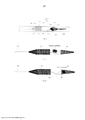
[015] A FIG. 1 é uma vista lateral de um dispositivo de remoção de coágulo totalmente expandido de acordo com uma primeira forma de realização da presente invenção.[015] FIG. 1 is a side view of a fully expanded clot removal device in accordance with a first embodiment of the present invention.
[016] A FIG. 2 é uma vista lateral do dispositivo de remoção de coágulo da FIG. 1 mostrado em uma orientação compactada dentro de um microcateter.[016] FIG. 2 is a side view of the clot removal device of FIG. 1 shown in a compacted orientation within a microcatheter.
[017] A FIG. 3A é uma vista lateral do dispositivo de remoção de coágulo das FIGS. 1 e 2 mostrada com o membro de tratamento expansível totalmente empurrado para fora do microcateter.[017] FIG. 3A is a side view of the clot removal device of FIGS. 1 and 2 shown with the expandable treatment member fully pushed out of the microcatheter.
[018] A FIG. 3B é uma vista lateral do dispositivo de remoção de coágulo das FIGS. 1 e 2 mostrada com os braços de controle e o membro de tratamento expansível levemente empurrado para fora do microcateter.[018] FIG. 3B is a side view of the clot removal device of FIGS. 1 and 2 shown with the control arms and the expandable treatment member slightly pushed out of the microcatheter.
[019] A FIG. 4 é uma vista lateral de um dispositivo de remoção de coágulo totalmente expandido de acordo com uma segunda forma de realização da presente invenção.[019] FIG. 4 is a side view of a fully expanded clot removal device according to a second embodiment of the present invention.
[020] A FIG. 5 é uma vista lateral do dispositivo de remoção de coágulo da FIG. 4 mostrando a coleta de um coágulo em um vaso.[020] FIG. 5 is a side view of the clot removal device of FIG. 4 showing the collection of a clot in a vessel.
[021] A FIG. 6A é uma vista lateral do dispositivo de remoção de coágulo da FIG. 4 mostrando o coágulo coletado dentro do membro de tratamento expansível.[021] FIG. 6A is a side view of the clot removal device of FIG. 4 showing the collected clot within the expandable treatment limb.
[022] A FIG. 6B é uma vista lateral do dispositivo de remoção de coágulo da FIG. 4 mostrando o coágulo coletado dentro do membro de tratamento expansível, e o membro de tratamento expansível dentro do restritor de fluxo proximal.[022] FIG. 6B is a side view of the clot removal device of FIG. 4 showing the collected clot within the expandable treatment limb, and the expandable treatment limb within the proximal flow restrictor.
[023] A FIG. 7 é uma vista lateral de um dispositivo de remoção de coágulo totalmente expandido de acordo com uma terceira forma de realização da presente invenção mostrado com um coágulo acoplado na superfície, e entre os espaços celulares, do membro de tratamento expansível.[023] FIG. 7 is a side view of a fully expanded clot removal device according to a third embodiment of the present invention shown with a clot attached to the surface, and between the cellular spaces, of the expandable treatment member.
[024] A FIG. 8 é uma vista lateral do dispositivo de remoção de coágulo da FIG. 7 mostrando o membro de tratamento expansível sendo puxado para o restritor de fluxo proximal.[024] FIG. 8 is a side view of the clot removal device of FIG. 7 showing the expandable treatment member being pulled into the proximal flow restrictor.
[025] A FIG. 9 é uma vista lateral do dispositivo de remoção de coágulo da FIG. 7 mostrando o membro de tratamento expansível dentro do restritor de fluxo proximal.[025] FIG. 9 is a side view of the clot removal device of FIG. 7 showing the expandable treatment member within the proximal flow restrictor.
[026] A FIG. 10 é uma vista lateral de um dispositivo de remoção de coágulo totalmente expandido de acordo com uma quarta forma de realização da presente invenção.[026] FIG. 10 is a side view of a fully expanded clot removal device according to a fourth embodiment of the present invention.
[027] A FIG. 11 é uma vista lateral do dispositivo de remoção da FIG. 10 mostrando o membro de tratamento expansível sendo empurrado para dentro do restritor de fluxo proximal com o coágulo acoplado em sua superfície externa.[027] FIG. 11 is a side view of the removal device of FIG. 10 showing the expandable treatment member being pushed into the proximal flow restrictor with the clot attached to its outer surface.
[028] A FIG. 12 é uma vista lateral do dispositivo de remoção da FIG. 10 mostrando o membro de tratamento expansível dentro do restritor de fluxo proximal.[028] FIG. 12 is a side view of the removal device of FIG. 10 showing the expandable treatment member within the proximal flow restrictor.
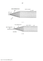
[029] A FIG. 13A é uma vista lateral ampliada de um projeto de restritor de fluxo proximal exemplar.[029] FIG. 13A is an enlarged side view of an exemplary proximal flow restrictor design.
[030] A FIG. 13B é uma vista lateral ampliada de um projeto de restritor de fluxo proximal exemplar com um fio de pressão ligado a partir da extremidade proximal.[030] FIG. 13B is an enlarged side view of an exemplary proximal flow restrictor design with a pressure wire attached from the proximal end.
[031] A FIG. 13C é uma vista lateral ampliada de um projeto de restritor de fluxo proximal exemplar com um lúmen de passagem no elemento de distribuição a partir da extremidade proximal.[031] FIG. 13C is an enlarged side view of an exemplary proximal flow restrictor design with a lumen passing through the dispensing member from the proximal end.
[032] A FIG. 14A é uma aplicação exemplificativa do restritor de fluxo proximal da FIG. 13B combinado com um cateter de acesso, como um cateter-guia, ou outros cateteres de suporte a procedimentos (não em posição de aspiração).[032] FIG. 14A is an exemplary application of the proximal flow restrictor of FIG. 13B combined with an access catheter, such as a guide catheter, or other procedural support catheters (not in suction position).
[033] A FIG. 14B é uma aplicação exemplificativa do restritor de fluxo proximal da FIG. 13B combinado com um cateter de acesso, como um cateter-guia, ou outros cateteres de suporte a procedimento, em uma posição de aspiração.[033] FIG. 14B is an exemplary application of the proximal flow restrictor of FIG. 13B combined with an access catheter, such as a guide catheter, or other procedural support catheters, in a suction position.
[034] As FIGS. 15A-15C ilustram outra forma de realização do dispositivo de remoção de coágulo de acordo com a presente invenção, em que o membro de tratamento expansível é omitido.[034] FIGS. 15A-15C illustrate another embodiment of the clot removal device according to the present invention, in which the expandable treatment member is omitted.
[035] A seguinte descrição detalhada trata-se de um dos melhores modos presentemente contemplados na realização da invenção. Esta descrição não deve ser tomada num sentido limitante, mas é feita meramente com o propósito de ilustrar princípios gerais de formas de realização da invenção. O âmbito da invenção é mais bem definido pelas reivindicações anexas.[035] The following detailed description is one of the best modes presently contemplated in carrying out the invention. This description should not be taken in a limiting sense, but is merely for the purpose of illustrating general principles of embodiments of the invention. The scope of the invention is better defined by the appended claims.
[036] A presente invenção é dirigida a um dispositivo para remoção de êmbolos e outros bloqueios luminais. O dispositivo inclui um membro de tratamento expansível, tal como uma malha ou uma grade, que está associado a um restritor de fluxo proximal. Durante o tratamento, o membro de tratamento expansível está posicionado dentro ou distalmente a um êmbolo dentro de um vaso sanguíneo e depois transita para um estado expandido. Em certas formas de realização, o estado normal do membro de tratamento expansível é a configuração expandida, e o membro de tratamento expansível é compactado e distribuído ao local de tratamento na configuração compactada através de uma bainha de implantação ou cateter. O membro de tratamento expansível é implantado a partir da bainha de implantação, o que faz com que ele retorne ao seu perfil expandido normal pela energia elástica armazenada no dispositivo. A expansão do membro de tratamento expansível acopla o membro de tratamento expansível com o êmbolo ou coágulo no local do bloqueio. Além disso, o restritor de fluxo proximal também pode se expandir para um estado de maior diâmetro quando é implantado a partir da bainha de implantação ou cateter. A expansão do restritor de fluxo proximal limita ou restringe, vantajosamente, o fluxo sanguíneo para frente e cria um gradiente de pressão dentro do vaso sanguíneo entre localizações distais e proximais do restritor de fluxo. O gradiente de pressão ajuda a evitar que os coágulos sejam descarregados para longe do membro de tratamento, auxiliando assim na remoção do êmbolo do vaso sanguíneo. Especificamente, a diferença de pressão pode agir como um vácuo para auxiliar na remoção do êmbolo do vaso sanguíneo. Após expansão, o membro de tratamento expansível e os êmbolos acoplados com o membro de tratamento expansível são removidos do vaso sanguíneo. Durante a remoção do coágulo, o membro de tratamento expansível (com o coágulo de sangue acoplado) também pode ser puxado dentro do restritor de fluxo proximal primeiro (ou seja, o componente de remoção de coágulo com coágulos acoplados é alojado dentro do restritor proximal) e então puxados de volta para o cateter guia e removidos do vaso sanguíneo. Além disso, a sucção a vácuo/aspiração pode ser aplicada através do lúmen do lúmen de cateter de acesso e do restritor de fluxo proximal para evitar que os coágulos se separem e escorram a jusante.[036] The present invention is directed to a device for removing emboli and other luminal blockages. The device includes an expandable treatment member, such as a mesh or grid, that is associated with a proximal flow restrictor. During treatment, the expandable treatment member is positioned within or distal to a plunger within a blood vessel and then transitions to an expanded state. In certain embodiments, the default state of the expandable treatment member is the expanded configuration, and the expandable treatment member is compressed and delivered to the treatment site in the compressed configuration via an implantation sheath or catheter. The expandable treatment limb is deployed from the implantation sheath, which is returned to its normal expanded profile by the elastic energy stored in the device. Expanding the expandable treatment member couples the expandable treatment member with the plunger or clot at the site of the blockage. In addition, the proximal flow restrictor can also expand to a larger diameter state when it is deployed from the implantation sheath or catheter. Expansion of the proximal flow restrictor advantageously limits or restricts forward blood flow and creates a pressure gradient within the blood vessel between distal and proximal locations of the flow restrictor. The pressure gradient helps to prevent clots from being discharged away from the treatment limb, thereby assisting in removing the embolus from the blood vessel. Specifically, the pressure difference can act as a vacuum to aid in removing the embolus from the blood vessel. After expansion, the expandable treatment member and the plungers coupled with the expandable treatment member are removed from the blood vessel. During clot removal, the expandable treatment limb (with the attached blood clot) may also be pulled into the proximal flow restrictor first (i.e., the clot removal component with attached clots is housed within the proximal restrictor) and then pulled back into the guiding catheter and removed from the blood vessel. In addition, vacuum suction/aspiration can be applied through the lumen of the access catheter lumen and the proximal flow restrictor to prevent clots from separating and flowing downstream.
[037] Além disso, o restritor de fluxo proximal regula o fluxo sanguíneo para frente e permite a restauração controlada (gradual) do fluxo sanguíneo e reduz o risco de siCH (Hemorragia Intra-cerebral sintomática) após a remoção intra-arterial de coágulos em pacientes com AVC agudo.[037] In addition, the proximal flow restrictor regulates forward blood flow and allows controlled (gradual) restoration of blood flow and reduces the risk of siCH (Symptomatic Intra-Cerebral Hemorrhage) after intra-arterial removal of clots in patients with acute stroke.
[038] Os dispositivos da presente invenção são adequados para a remoção de bloqueios em lúmens corporais e são particularmente bem adequados para remoção de trombos, êmbolos ou ateroma na vasculatura, incluindo os das artérias e veias. Entende-se que as dimensões do dispositivo podem ser modificadas para se adequarem a uma aplicação particular. Por exemplo, os dispositivos da invenção utilizados para o tratamento de trombose venosa profunda podem ter uma seção transversal maior do que os dispositivos da invenção utilizados para tratamento de isquemia cerebral.[038] The devices of the present invention are suitable for removing blockages in body lumens and are particularly well suited for removing thrombi, emboli, or atheroma in the vasculature, including those of arteries and veins. It is understood that the dimensions of the device can be modified to suit a particular application. For example, devices of the invention used to treat deep vein thrombosis may have a larger cross-section than devices of the invention used to treat cerebral ischemia.
[039] Comparado com os dispositivos de trombectomia mecânica existentes, o projeto de dispositivo singular, incluído nesta invenção tem a vantagem de fornecer uma característica de restrição de fluxo proximal para bloquear o fluxo dianteiro do sangue quando o dispositivo é implantado durante uso. Esse recurso pode ajudar a eliminar ou reduzir o risco de irrigação, ou a quebra dos coágulos sanguíneos durante o procedimento.[039] Compared to existing mechanical thrombectomy devices, the unique device design included in this invention has the advantage of providing a proximal flow restriction feature to block the forward flow of blood when the device is implanted during use. This feature can help eliminate or reduce the risk of irrigation, or the breakdown of blood clots during the procedure.
[040] Outra vantagem importante proporcionada pela presente invenção é o lúmen central do restritor de fluxo proximal poder ser usado ou combinado com o lúmen do cateter de acesso para aplicar força de aspiração/sucção para ajudar na remoção completa dos coágulos sanguíneos na vasculatura.[040] Another important advantage provided by the present invention is that the central lumen of the proximal flow restrictor can be used or combined with the lumen of the access catheter to apply aspiration/suction force to aid in the complete removal of blood clots in the vasculature.
[041] Assim, o dispositivo descrito na presente invenção supera as deficiências das tecnologias existentes e pode ser liberado à vasculatura alvo suavemente, podendo ser retirado com segurança, e pode remover todo o êmbolo com menos passagens. Em uso, o dispositivo de trombectomia mecânica descrito na presente invenção pode ser compactado a um perfil baixo e carregado num sistema de entrega ao local alvo no vaso por um procedimento médico, tal como por meio do emprego de um cateter de entrega. O dispositivo mecânico de trombectomia pode ser liberado do sistema de entrega quando ele atinge o local de implante alvo e expandido para o seu perfil expandido normal pela energia elástica armazenada no dispositivo (dispositivo auto expansível).[041] Thus, the device described in the present invention overcomes the shortcomings of existing technologies and can be released to the target vasculature smoothly, can be safely withdrawn, and can remove the entire plunger with fewer passes. In use, the mechanical thrombectomy device described in the present invention can be compacted to a low profile and loaded into a delivery system to the target site in the vessel by a medical procedure, such as through the use of a delivery catheter. The mechanical thrombectomy device can be released from the delivery system when it reaches the target implant site and expanded to its normal expanded profile by the elastic energy stored in the device (self-expanding device).
[042] Quanto à posição relativa do membro de tratamento expansível em relação ao êmbolo ou coágulo sanguíneo, este pode ser implantado no local do êmbolo ou implantado distalmente ao êmbolo. Ao lidar com êmbolos longos, o membro de tratamento expansível pode também ser usado para remover o êmbolo da parte proximal para a parte distal com múltiplas passagens, até todo o êmbolo ser removido.[042] As for the relative position of the expandable treatment limb in relation to the plunger or blood clot, it can be implanted at the plunger site or implanted distally to the plunger. When dealing with long plungers, the expandable treatment member can also be used to remove the plunger from proximal to distal with multiple passes until the entire plunger is removed.
[043] Voltando agora aos desenhos, as FIGS. 1 e 2 ilustram um dispositivo 100 para remover êmbolos e outros bloqueios luminais de acordo com a presente invenção. O dispositivo 100 pode ser feito de uma peça ou de várias peças de material super elástico Nitinol™ ou de uma tubagem de liga super elástica Nitinol™. Também pode ser feito de outros materiais biocompatíveis que apresentam propriedades super-elásticas ou de memória de forma. O dispositivo 100 pode ser feito por corte a laser, usinagem mecânica, usinagem química, usinagem eletroquímica, EDM, revestimento trançado e técnicas relacionadas conhecidas dos especialistas na técnica.[043] Returning now to the drawings, FIGS. 1 and 2 illustrate a
[044] O dispositivo 100 tem um membro de tratamento expansível 102 transportado ao longo de um fio de entrega 104, adjacente à extremidade distal do fio de entrega 104. O fio de entrega 104 tem uma ponta distal macia 106 que se estende distalmente do membro de tratamento expansível 102 e tem uma bobina marcadora embutida no mesmo. Uma pluralidade de braços de controle de corte a laser 108 acoplam a parte proximal do membro de tratamento expansível 102 com um cubo 110 ao longo do fio de entrega 104. Especificamente, cada braço de controle 108 tem extremidades opostas ligando a parte proximal do membro de tratamento expansível 102 e o cubo 110. Um restritor de fluxo proximal 112 é transportado no fio de entrega 104 próximo ao cubo 110. Faixas marcadoras ou bobinas marcadoras podem ser incorporadas no restritor de fluxo proximal 112 e o membro de tratamento expansível 102 para melhor visibilidade. Pelo menos uma extremidade do restritor de fluxo proximal 112 pode se mover livremente ao longo do fio de entrega 104.[044] The
[045] O membro de tratamento expansível 102 pode ser configurado para atuar como um cesto de captura para o coágulo ou êmbolo, e nesta modalidade é conformado como um cone em sua configuração totalmente expandida, com um ápice 120 na parte mais distal do membro de tratamento expansível 102 fixo ao fio de entrega 104 adjacente à ponta distal 106 e com o membro de tratamento expansível 102 aumentando radialmente em diâmetro até atingir o seu anel mais proximal 122. O membro de tratamento expansível 102 pode ser feito de uma malha trançada Ntinol ™ e pode ser moldado na forma de cone por um processo térmico- mecânico. Mais significativamente, o membro de tratamento expansível 102 não é cilíndrico em configuração, o que permite que ele se adapte melhor ao contorno do vaso e se mova mais livremente dentro do vaso. O tamanho da abertura para o anel 122 pode variar de 0,5 mm a 12 mm. O comprimento da parte do cone distal do ápice 120 ao anel 122 pode variar de 2 mm a 40 mm.[045] The
[046] A armação de malha do membro de tratamento expansível 102 pode ser fornecida com uma série de aberturas. Os membros de estrutura ou escoras formam o corpo da estrutura de malha e definem a pluralidade de aberturas. Em certas formas de realização, os elementos de estrutura são uma pluralidade de fios de interseção ou outros fios. Os elementos de estrutura podem formar uma malha ou uma estrutura semelhante a um espaço que define a pluralidade de aberturas. Em certas formas de realização, o membro de tratamento expansível 102 pode incluir uma pluralidade de saliências 150 na estrutura; Veja a FIG. 1. A pluralidade de saliências 150 prende ainda mais o êmbolo para remoção.[046] The mesh frame of the
[047] Como alternativa, ou além da pluralidade de saliências 150, o membro de tratamento expansível 102 pode incluir uma ou mais modificações ou tratamentos de superfície. Por exemplo, como explicado em maior detalhe abaixo, a superfície do membro de tratamento expansível 102 pode ser áspera para melhorar a aderência do coágulo. O principal eixo geométrico do membro de tratamento expansível 102 pode ser desviado ou diferente do eixo central longitudinal do vaso sanguíneo nativo. Quando o membro de tratamento expansível 102 estiver uso, tanto o cateter de entrega (por exemplo, microcateter 124) e/ou o eixo de movimento do membro de tratamento expansível 102 podem ser diferentes do eixo central longitudinal do vaso e podem entrar em contato com a parede lateral do vaso sanguíneo.[047] Alternatively, or in addition to the plurality of
[048] O fio de entrega 104 pode ser feito de fio de Nitinol super elástico, fio de aço inoxidável, fio de aço inoxidável trançado. Liga de Co-Cr e outros materiais biocompatíveis. O diâmetro do fio de entrega 104 pode variar de 0,2032 mm a 0,762 mm e o fio de entrega 104 pode ter diâmetros/rigidez variáveis ao longo do seu comprimento.[048] The
[049] Esta ponta distal 106 pode ser feita de ligas de Ta, Pt, W, Pt-W ou Pt-lr para radiopacidade e de bobinas ou marcadores radiopacos.[049] This
[050] Os braços de controle 108 podem ser cortados a laser a partir de um material de Nitinol super elástico. Eles são de preferência esticados quando o membro de tratamento expansível 102 está na sua configuração expandida completa. Os braços de controle 108 funcionam para controlar o diâmetro de abertura do anel 122, de modo que o diâmetro maior do anel 122 possa ser conseguido quando os braços de controle 108 são completamente empurrados para fora da bainha de um microcateter 124 (ver a FIG. 2). O diâmetro do anel 122 pode ser ajustado pelo comprimento dos braços de controle 108 sendo empurrados para fora do microcateter 124. Embora as presentes formas de realização sejam descritas como tendo três braços de controle 108, é possível proporcionar um ou mais do que dois braços de controle 108.[050] The
[051] O cubo 110 pode ser feito de materiais radiopacos e pode mover-se livremente ao longo e em relação ao fio de entrega 104. O cubo 110 também pode ser preso a um local fixo ao longo do fio de entrega 104.[051] The
[052] O restritor de fluxo proximal 112 pode ser uma estrutura bulbosa e pode ser feito de uma malha Nitinol™, e está fixamente ligado ao fio de entrega 104 na sua extremidade proximal, enquanto a extremidade distal do restritor de fluxo proximal 112 pode mover-se livremente ao longo e com respeito ao fio de entrega 104. Em outra forma de realização, o restritor de fluxo proximal 112 pode ser ligado de modo fixo ao fio de entrega 104 na sua extremidade distal, enquanto a extremidade proximal do restritor de fluxo proximal 112 pode mover-se livremente ao longo e em relação ao fio de entrega 104. O restritor de fluxo proximal 112 pode ter um primeiro perfil compactado menor para entrega através do possível microcateter 124. O restritor de fluxo proximal 112 pode ter um segundo maior diâmetro/perfil expandido, quando liberado do microcateter 124 ou outro sistema de entrega para bloquear, limitar ou restringir o fluxo sanguíneo. A estrutura bulbosa pode ser uma estrutura trançada ou cortada a laser, e feita de um filme, membrana, material trançado ou com reticulado. Em certas formas de realização, o restritor de fluxo proximal 112 é um filme ou membrana polimérica. Em outras formas de realização, o restritor de fluxo proximal 112 é uma rede trançada ou tecida formada a partir de um metal, polímero ou combinação destes. O tipo e o material do restritor de fluxo proximal 212 podem ser escolhidos com base na cobertura desejada (isto é, quantidade de fluxo a ser reduzida). A superfície do restritor de fluxo proximal pode ser total ou parcialmente coberta por alguns materiais poliméricos para restringir o fluxo sanguíneo. Pode ser fabricado a partir de um ou dois elementos do dispositivo 100, ou fabricado a partir de outras peças de material, depois ligado ao fio de entrega 104 por meios mecânicos, ou por meio de um processo térmico (laser ou soldadura) ou adesivo / cola ou tecnologia termo-retrátil. A estrutura bulbosa também pode ser fabricada a partir da mesma peça de tubagem Nitinol™ daquela do dispositivo 100, por corte a laser ou processos químicos e, em seguida, moldada a um diâmetro maior do que a tubagem Nitinol™ bruta.[052] The
[053] O restritor de fluxo proximal 112 pode ter um diâmetro na sua configuração totalmente expandida que, é aproximadamente, igual ao diâmetro do anel de abertura 122 do membro de tratamento expansível 102 quando o membro de tratamento expansível 102 está sua configuração totalmente expandida. O diâmetro do restritor de fluxo proximal 112 pode variar de 0,5 mm a 12 mm, e seu comprimento pode variar de 2 mm a 60 mm.[053] The
[054] Marcadores radiopacos podem ser fixados em qualquer parte do dispositivo 100 para posicionamento. Uma maneira de proporcionar visibilidade total para o dispositivo 100 é trabalhar com um material radiopaco através do lúmen inteiro ou parcial do fio de entrega 104. Marcadores também podem ser colocados no membro de tratamento expansível 102 para auxiliar no posicionamento. Além disso, marcadores radiopacos (bobinas marcadoras, faixas marcadoras, fios radiopacos, revestimentos radiopacos, etc.) podem ser integrados ao restritor de fluxo proximal 112.[054] Radiopaque markers can be attached to any part of the
[055] O dispositivo 100 pode ter um tratamento de superfície em partes selecionadas a fim de melhorar o desempenho das partes selecionadas do dispositivo 100. Tanto o restritor de fluxo proximal 112 como o membro de tratamento expansível 102 podem ser revestidos ou cobertos, total ou parcialmente, por materiais biocompatíveis típicos para lubricidade. A superfície do membro de tratamento expansível 102 pode ter uma carga positiva ou negativa para melhor adesão dos coágulos. A superfície do membro de tratamento expansível 102 também pode ser, mecanicamente ou quimicamente tratada para ter uma superfície "rugosa" para melhor adesividade dos coágulos. A superfície "rugosa" pode ser adquirida por (i) um revestimento ou camada de superfície porosa (ii) uma superfície micro jateada ou microagulhamento, ou (iii) uma geometria ou arranjo de suporte irregular.[055] The
[056] O membro de tratamento expansível 102 pode ser revestido total ou parcialmente com produto(s) químico(s), fármaco(s) ou outros bioagentes para evitar a coagulação e /ou para a melhor adesão entre o dispositivo e o êmbolo. Além disso, as superfícies do membro de tratamento expansível 102 e do restritor de fluxo proximal 112 podem ser tratadas para formar camadas superficiais diferentes (por exemplo, camada de oxidação, camada superficial nitro- ou carbonizada ou N-C combinada, etc.) para melhor adesão entre o membro de tratamento expansível 102 e o êmbolo.[056] The
[057] A FIG. 2 mostra o dispositivo 100 comprimido e encaixado dentro de um microcateter 124. Em utilização, um fio guia pode ser inserido através da vasculatura no local de tratamento alvo e, depois, o microcateter 124 é introduzido por cima do fio guia para um local alvo num vaso com o dispositivo 100 alojado utilizando técnicas de entrega convencionais que são conhecidas dos peritos na arte. Em alternativa, o microcateter 124 pode ser inserido primeiro sobre o fio guia, depois o dispositivo compactado 100 pode ser inserido através do lúmen interno do microcateter 124. A extremidade distal do microcateter 124 pode ser posicionada próxima ou no interior, ou distal ao coágulo ou êmbolo no local alvo, não havendo necessidade do microcateter 124 atravessar o coágulo ou êmbolo, minimizando assim a possibilidade de empurrar o coágulo ou o êmbolo a jusante do vaso.[057] FIG. 2 shows the
[058] O microcateter 124 pode então ser puxado de volta (proximalmente) para expor, primeiro o membro de tratamento expansível 102 (ver a FIG. 3A), depois os braços de controle 108 e depois mais tarde, o restritor de fluxo proximal 112. Antes dos braços de controle 108 estarem totalmente expostos, o membro de tratamento expansível 102 não atingirá o seu diâmetro total, o que torna possível para o membro de tratamento expansível 102 não atingir os coágulos antes do dispositivo 100 atingir a sua posição desejada. Em vez de puxar de volta o microcateter 124, é também possível dispor o membro de tratamento expansível 102 inserindo o dispositivo 100 no microcateter 124 até a ponta distal 106 atingir a extremidade distal do microcateter 124 e, em seguida, segurando a extremidade proximal do microcateter 124 numa posição estacionária, empurrar o dispositivo 100 distalmente para fora do microcateter 124. Sob esta alternativa, não há necessidade de retirar o microcateter 124, o que permite um posicionamento mais apurado. O membro de tratamento expansível 102 não se instala totalmente (isto é alcança o seu maior diâmetro) até que os braços de controle 108 terem sido completamente empurrados para fora do microcateter 24. Isto permite um intervalo, volume ou espaço (ver a FIG. 3B) entre o membro de tratamento expansível 102 e o coágulo real no vaso, de modo que o coágulo não será empurrado a jusante e desalojado pelo membro de tratamento expansível 102, quando o membro de tratamento expansível 102 é empurrado para fora do microcateter 124 e localizado distalmente ao coágulo. Uma vez que os braços de controle 108 tenham sido completamente empurrados para fora do microcateter 124, então o membro de tratamento expansível 102 atingirá o seu diâmetro total para capturar o coágulo do lado distal do coágulo. Neste ponto, o microcateter 124 e o fio de entrega alongado 102 serão recuados ou retirados ao mesmo tempo para remover o coágulo.[058] The
[059] Durante este procedimento, o restritor de fluxo proximal 112 elimina ou reduz o fluxo sanguíneo frontal a fim de minimizar o risco de retenção de coágulo inferior e desalojamento do coágulo. O membro de tratamento expansível 102 pode recolher todos os coágulos / êmbolos para evitar que fluam a jusante. O restritor de fluxo proximal 112 também regula o fluxo de sangue durante e imediatamente após o procedimento para eliminar o efeito do sICH para um melhor resultado clínico.[059] During this procedure, the
[060] Em outras formas de realização, o restritor de fluxo proximal pode envolver (i) uma superfície externa ou diâmetro de uma parte proximal do membro de tratamento expansível ou (ii) tanto as superfícies interna e externa ou os diâmetros da parte proximal do membro de tratamento expansível. Nestas formas de realização, o restritor de fluxo proximal pode cobrir um comprimento que se estende entre (1) uma extremidade proximal do membro de tratamento expansível até cerca da metade do comprimento do membro de tratamento expansível, ou (ii) entre uma extremidade proximal do membro de tratamento expansível a cerca de % o do comprimento do membro de tratamento expansível.[060] In other embodiments, the proximal flow restrictor may surround (i) an outer surface or diameter of a proximal portion of the expandable treatment member or (ii) both the inner and outer surfaces or diameters of the proximal portion of the expandable treatment member. In these embodiments, the proximal flow restrictor can span a length extending from (1) a proximal end of the expandable treatment member to about half the length of the expandable treatment member, or (ii) between a proximal end of the expandable treatment member expandable treatment member to about % of the length of the expandable treatment member.
[061] Por exemplo, as FIGS. 4 e 6 ilustram outra forma de realização de um dispositivo 200 para remoção de êmbolos e outros bloqueios luminais. O dispositivo 200 também tem um membro de tratamento expansível 202, uma ponta distal macia 206 (com uma bobina marcadora), um fio de entrega 204, braços de controle 208, um cubo 210 e um restritor de fluxo proximal 212 que correspondem ao membro de tratamento expansível 102, ponta distal macia 106 (com bobina marcada), fio de entrega 104, braços de controle 108, cubo 110 e restritor de fluxo proximal 112, respectivamente, para a primeira concretização, com exceção de algumas diferenças.[061] For example, FIGS. 4 and 6 illustrate another embodiment of a device 200 for removing emboli and other luminal blockages. Device 200 also has an
[062] Em primeiro lugar, o membro de tratamento expansível 202 tem uma configuração ligeiramente diferente. Em vez da configuração cônica do membro de tratamento expansível 102, o membro de tratamento expansível 202 tem um corpo tronco-cônico 228 em que a sua extremidade mais distal não termina num ápice, mas tem uma pequena abertura distal.[062] First, the
[063] Em segundo lugar, o restritor de fluxo proximal 212 tem uma configuração diferente, tendo um corpo que inclui uma seção distal cilíndrica 230 e uma seção proximal geralmente cônica (ou frustocônica) 232 que tem uma configuração afunilada. As duas seções 230 e 232 combinam-se para definir uma seção de recepção.[063] Second, the
[064] O corpo 228 e as seções 230 e 232 podem ser todos cortados a laser a partir do mesmo material (por exemplo, uma tubagem ou folha Nitinol™), mas os tamanhos das células ou aberturas 234 no corpo 228 e as seções 230 e 232 podem variar para variar a flexibilidade do corpo diferente 228 ou seções 230, 232. A seção 232 pode ter uma borda distal anular 240 que funciona como uma boca aberta. As seções 230 e 232 também podem diferentes tamanhos /porosidades e podem ser cobertas por um polímero biocompatível ou deixadas descobertas. Um exemplo é deixar a seção 232 descoberta, cobrindo a seção 230. A seção descoberta 232 pode ser incorporada com outros cateteres de acesso para facilitar a função de aspiração / sucção. O restritor de fluxo proximal 112 pode ter uma configuração trançada.[064] The
[065] Terceiro, o fio de entrega 204 pode ter uma seção defletida 238 que se prolonga distalmente a partir da seção 230 num ângulo em relação ao eixo longitudinal central ao cubo 210, que está deslocado do eixo longitudinal central ocupado pelo fio de entrega 204. A este respeito, os braços de controle 208 prolongam-se a partir do cubo 210 em direção ao corpo 228 em diferentes ângulos. Os diferentes ângulos permitem que o membro de tratamento expansível 202 percorra, mais facilmente, pela anatomia vascular e também facilita melhor a coleta de coágulos e partículas pelo membro de tratamento expansível 202. Além disso, os diferentes ângulos para os braços de controle 208 permitem que a abertura proximal do membro de tratamento expansível 202 permaneça aberta e não colapse durante o procedimento. Os diferentes ângulos também facilitam para os braços de controle 208 o controle do diâmetro ou o posicionamento planejado do membro de tratamento expansível 202 durante o procedimento.[065] Third, the
[066] O restritor de fluxo proximal 212 é configurado de modo a poder experimentar um movimento relativo em relação ao membro de tratamento expansível 202. Isto é realizado por não ter uma ligação fixa entre o restritor de fluxo proximal 212 e o fio de entrega 204, e permitindo que o restritor de fluxo proximal 212 deslize ao longo do fio de entrega 204. Em outras palavras, o membro de tratamento expansível 202 pode mover-se independentemente do restritor de fluxo proximal 212. Isto proporciona uma captura e remoção mais eficaz do coágulo conforme descrito abaixo.[066] The
[067] Em utilização, o dispositivo 200 é introduzido dentro de um microcateter 124, que é entregue numa localização alvo em um vaso com o dispositivo 200 aí alojado utilizando técnicas de entrega convencionais que são conhecidas dos peritos na técnica. A extremidade distal do microcateter 124 pode, de novo, ser posicionada proximal a, ou no interior, do coágulo ou do êmbolo no local alvo e não há necessidade do microcateter 124 atravessar o coágulo ou o êmbolo. O dispositivo 200 pode então ser empurrado distalmente para fora da extremidade distal do microcateter 124 para expor, primeiro, o membro de tratamento expansível 202 e a seguir, o restritor de fluxo proximal 212. Veja a FIG. 5. O dispositivo 200 é então puxado para trás ou retirado para que o membro de tratamento expansível 202 capture o coágulo. Veja a FIG. 6A. Quando o fio de entrega 204 é puxado de volta e o membro de tratamento expansível 202 é puxado de volta com ele, o restritor de fluxo proximal 212 pode ficar no mesmo local dentro do vaso, de modo que, quando a borda distal anular 240 do restritor de fluxo proximal 212 contata a borda proximal anular ou o anel 222 do corpo 228, e a retirada proximal do fio de entrega 204 fará com que o membro de tratamento expansível 202 seja puxado de volta para a seção cilíndrica 230, de modo que todo o dispositivo 200 seja removido do vaso. Como resultado, todo o coágulo ou êmbolo pode ser retido dentro de um espaço definido pelo membro de tratamento expansível 202 e o restritor de fluxo proximal 212 durante a remoção, de modo a impedir o deslocamento ou o desencaixe do coágulo. Veja a FIG. 6B. O diâmetro expandido da borda proximal anular 222 é de preferência ligeiramente menor do que o diâmetro expandido da seção cilíndrica 230 e de sua borda anular proximal 240, de modo que o membro de tratamento expansível 202 pode ficar retido dentro da seção cilíndrica 230.[067] In use, the device 200 is inserted into a
[068] Além disso, é possível fornecer o fio de entrega 204 com um lúmen que se abre numa abertura localizada dentro do restritor de fluxo proximal 212 (ver as Figs. 13 e 14 abaixo), de modo que a sucção pode ser aplicada a partir da extremidade proximal dos cateteres ou microcateteres guia de acesso 124 para coletar coágulos e partículas menores no restritor de fluxo proximal 212 utilizando força de sucção, e em seguida, removidos do vaso.[068] Furthermore, it is possible to provide the
[069] Finalmente, a ação de sucção/aspiração através do lúmen dos dispositivos de acesso e o encapsulamento do membro de tratamento expansível 102 (com o coágulo acoplado) pode acontecer, simultaneamente, ou em sequência durante o procedimento.[069] Finally, the suction/aspiration action through the lumen of the access devices and the encapsulation of the expandable treatment member 102 (with the clot attached) can happen simultaneously or in sequence during the procedure.
[070] As FIGS. 7 a 9 ilustram outra forma de realização de um dispositivo 300 para remoção de êmbolos e outros bloqueios luminais. O dispositivo 300 é semelhante ao dispositivo 200 por ter também um membro de tratamento expansível 302, um fio de entrega 304, um cubo 310 e um restritor de fluxo proximal 312 que correspondem ao membro de tratamento expansível 202, fio de entrega 204, cubo 210 e restritor de fluxo proximal 212, respectivamente, para a segunda concretização, com exceção de algumas diferenças.[070] FIGS. 7-9 illustrate another embodiment of a
[071] Primeiramente, o membro de tratamento expansível 302 tem uma configuração diferente, e pode ser configurado como qualquer um dos dispositivos de remoção divulgados na publicação copendente dos Estados Unidos No. 2015-0150672, depositada em 16 de janeiro de 2015, cuja completa divulgação está incorporada por esta referência como se fosse aqui totalmente apresentada. Por esse motivo, não há fios de controle 108/208.[071] First, the
[072] Em segundo lugar, o restritor de fluxo proximal 312 pode ser essencialmente o mesmo que o restritor de fluxo proximal 212 nas FIGS. 4-6[072] Second, the
[073] Em terceiro lugar, o cubo 310 pode funcionar como um marcador ou restritor. Durante o procedimento, quando o membro de tratamento expansível 302 está sendo puxado de volta, o membro de tratamento expansível 302 começará a puxar o restritor de fluxo proximal 312 com ele, assim que o cubo 310 alcançar e encaixar a extremidade proximal do interior do restritor de fluxo proximal 312. Nesta fase, todo o membro de tratamento expansível 302 (ou parte dele) com o seu coágulo recolhido já estaria retido dentro do restritor de fluxo proximal 312. Mais uma vez, a força de sucção pode ser aplicada a partir da extremidade proximal do cateter ou microcateter guia de acesso para auxiliar na retirada de todos os coágulos/êmbolos dentro do restritor de fluxo proximal 312.[073] Third, the
[074] Novamente, o corpo do membro de tratamento expansível 302 e as seções do restritor de fluxo proximal 312 podem ser todos cortados a laser a partir do mesmo material (por exemplo, um tubo ou folha de Nitinol™), mas os tamanhos das células ou aberturas no expansível o membro de tratamento 302 e o restritor de fluxo proximal 312 podem variar a fim de se conseguir várias flexibilidades. A parte afunilada proximal no restritor de fluxo proximal 312 pode ser descoberta, enquanto a parte reta do restritor de fluxo proximal 312 pode ser coberta, para alcançar o efeito e o controle de sucção desejados.[074] Again, the body of the
[075] Como mostrado na FIG. 7, o coágulo pode ser capturado na superfície dentre os espaços celulares, do membro de tratamento expansível 302, e o membro de tratamento expansível 302 é puxado para dentro do restritor de fluxo proximal 312 (ver FIGS. 8 e 9) completamente antes de todo sistema ser (microcateter e dispositivo 300) ser removido do vaso sanguíneo. Uma vez que o restritor de fluxo proximal 312 não tem nenhuma articulação fixa com o fio de entrega 304, pode permanecer num local fixo em relação ao fio de entrega 304 e ao membro de tratamento expansível 302 de modo que o membro de tratamento expansível 302 (com o coágulo de sangue nele aprisionado) pode ser puxado para dentro do restritor de fluxo proximal 312. O membro de tratamento expansível 302 pode ser puxado para dentro do restritor de fluxo proximal 312 até que o cubo 310 (que age como um tampão) entre em contato com a parte afunilada da seção proximal 332 do restritor de fluxo proximal 312. A parte proximal do membro de tratamento expansível 302 tem uma configuração afunilada de modo que pode se encaixar na seção proximal estreitada 332. Neste momento, o restritor de fluxo proximal 312 irá mover-se juntamente com o membro de tratamento expansível 302 (e o coágulo de sangue alojado no interior) quando o fio de entrega 304 é puxado para fora. O dispositivo 300 pode ser puxado dentro de um cateter guia para ser removido do vaso, ou pode ser removido para fora do vaso sem ser puxado para dentro de um cateter guia primeiro. Mais uma vez, a força de sucção pode ser aplicada a partir da extremidade proximal do cateter ou microcateter guia de acesso para ajudar a retirar todos os coágulos / êmbolos dentro do restritor de fluxo proximal 312.[075] As shown in FIG. 7, the clot can be captured on the surface between the cellular spaces, of the
[076] As FIGS. 10 e 12 ilustram outra forma de realização de um dispositivo 400 para remoção de êmbolos e outros bloqueios luminais. O dispositivo 400 é semelhante ao dispositivo 100 na medida em que também tem um membro de tratamento expansível 402, um fio de entrega 404, a ponta distal 406 e um restritor de fluxo proximal 412 que correspondem ao membro de tratamento expansível 102, fio de entrega 104, ponta distal 106 e restritor de fluxo proximal 112, respectivamente, para a primeira concretização, com exceção de umas poucas diferenças.[076] FIGS. 10 and 12 illustrate another embodiment of a
[077] Em primeiro lugar, o membro de tratamento expansível 402 tem uma configuração diferente e tem uma seção distal 440 que é essencialmente a mesma que o corpo cônico do membro de tratamento expansível 102. No entanto, o membro de tratamento expansível 402 também tem uma seção proximal 442 que também é conformada conicamente com um ápice 444 na sua extremidade proximal e com a sua maior parte de diâmetro acoplada à parte de maior diâmetro da seção distal 440. A configuração duplamente cônica do membro de tratamento expansível 402 permite que a sua extremidade distal seja mais macia e menos traumática, e também proporciona uma extremidade proximal menos rígida, que em conjunto permitem uma passagem mais fácil da anatomia do vaso. A parte de tratamento expansível distal 402 pode ser total ou parcialmente coberta por materiais poliméricos para bloquear o fluxo sanguíneo (fluxo da parte distal do vaso para a parte proximal do vaso, de modo que o efeito de aspiração do cateter de acesso e do restritor de fluxo proximal seja mais eficaz).[077] First, the
[078] Em segundo lugar, o restritor de fluxo proximal 412 pode ser essencialmente o mesmo do restritor de fluxo proximal 212 nas FIGS. 4-6[078] Second, the
[079] Em terceiro lugar, não existe cubo 110 e nenhum fio de controle 108/208.[079] Third, there is no
[080] Mais uma vez, o corpo do membro de tratamento expansível 402 e as seções do restritor de fluxo proximal 412 podem ser todas cortadas a laser do mesmo material (por exemplo, um tubo ou folha Nitinol™), mas os tamanhos das células ou aberturas no membro de tratamento expansível 402 e o restritor de fluxo proximal 412 podem variar para se conseguir flexibilidades variadas.[080] Again, the body of the
[081] O coágulo pode ser acoplado no exterior da seção distal 442 (ver a FIG. 11) e o membro de tratamento expansível 402 pode ser puxado para dentro do restritor de fluxo proximal 412 (ver as FIG. 11 e 12) completamente antes de todo o sistema (microcateter e dispositivo 300) serem removidos do vaso sanguíneo. Uma vez que o restritor de fluxo proximal 412 não tem nenhuma junta fixa com o fio de entrega 404, ele pode permanecer num local fixo em relação ao fio de entrega 404 e ao membro de tratamento expansível 402 de modo que o membro de tratamento expansível 402 (com o coágulo de sangue acoplado na sua superfície externa) possa ser puxado de dentro do restritor de fluxo proximal 412. A aspiração pode ser aplicada durante o procedimento através do lúmen do cateter de acesso ou do microcateter e também do restritor de fluxo proximal.[081] The clot can be attached to the outside of the distal section 442 (see FIG. 11) and the
[082] As Figuras 13A, 13B e 13C mostram algumas configurações de projeto exemplificativas para o restritor de fluxo proximal trançado. O restritor de fluxo proximal mostrado nas FIGS. 13A-3C e 14A-14B podem ser os mesmos do restritor de fluxo proximal 212, embora os princípios e conceitos incorporados nas FIGS. 13A-13C e 14A-14B também se aplicam aos outros restritores de fluxo proximal mostrados e descritos no presente.[082] Figures 13A, 13B and 13C show some exemplary design configurations for the braided proximal flow restrictor. The proximal flow restrictor shown in FIGS. 13A-3C and 14A-14B may be the same as for
[083] Como mostrado na FIG. 13B, o restritor de fluxo proximal 212 pode ter um lúmen central 260 na extremidade proximal 262, uma parte proximal cônica 232 e uma parte distal cilíndrica 230. A parte proximal 232 pode ser descoberta, e a parte distal 230 pode ser coberta por materiais poliméricos biocompatíveis. Em uso, a sucção pode ser aplicada através do lúmen central 260 dos cateteres de acesso.[083] As shown in FIG. 13B, the
[084] Como mostrado na FIG. 13B. um fio de pressão 264 pode ser conectado à parte proximal 232 para operar o restritor de fluxo proximal 212. Este projeto pode ser usado ou incorporado a outros dispositivos de remoção de coágulos disponíveis comercialmente, e também pode ser usado ou incorporado com um cateter de acesso, cateter guia, DAC ou microcateter para aplicar sucção durante o procedimento de remoção de coágulo.[084] As shown in FIG. 13B. a
[085] Como mostrado na FIG. 13C, uma estrutura de lúmen central diferente 260a tendo um lúmen pode ser ligada à parte proximal 232 para operar o restritor de fluxo proximal 212. Este projeto pode ser usado ou incorporado a outros dispositivos de remoção de coágulos disponíveis comercialmente, e também pode ser usado ou incorporado com um cateter de acesso, cateter guia, DAC ou microcateter para aplicar sucção durante o procedimento de remoção do coágulo.[085] As shown in FIG. 13C, a different
[086] As FIGs. 14A e 14B mostram uma aplicação exemplificativa da característica de restrição de fluxo proximal. A parte proximal 232 pode estar totalmente descoberta ou parcialmente descoberta, e a parte distal 230 pode ser coberta por materiais poliméricos biocompatíveis. Em uso, o restritor de fluxo proximal 212 pode ser fornecido ao local alvo através de um microcateter ou outro cateter de acesso 224. O lúmen central proximal 260 pode ser usado para deslizar ao longo de um fio guia ou fio de pressão 264 do dispositivo de remoção de coágulo. Ajustando a posição/localização relativa do microcateter 224 com aquela do restritor de fluxo proximal 212, pode-se permitir que o restritor de fluxo proximal 212 admita o fluxo frontal proximal ou cortar o fluxo frontal. Na situação em que o fluxo frontal é cortado, o efeito de sucção pode ser aplicado através do lúmen do microcateter 224 para melhorar a coleta, retenção e remoção de coágulos. Por exemplo, quando o fio de pressão 264 ligado ao restritor de fluxo proximal 212 é puxado de volta para o cateter de acesso ou microcateter 224, e a parte proximal não coberta 232 é completamente coberta pela extremidade distal do cateter de acesso ou microcateter 224 com a parte distal coberta 230 formando uma vedação com a extremidade distal do cateter ou microcateter de acesso 224, o fluxo frontal é totalmente cortado e em seguida, a aspiração /sucção pode ser aplicada a partir da extremidade proximal do cateter ou microcateter de acesso 224 para ajudar a reter e recolher ao coágulos (como mostrado na FIG. 14B). Da FIG. 14B, nota-se que o diâmetro externo do cateter de acesso 224 é inferior ao diâmetro externo da parte distal totalmente expandida 230, mas que esta junta ainda pode ser formada quando a extremidade proximal da parte distal 230 é puxada para dentro da abertura distal do cateter de acesso 224 quando a parte proximal da parte distal 230 começa a comprimir e assume uma configuração afunilada à medida que a parte distal 230 é puxada para dentro do cateter de acesso 224.[086] FIGs. 14A and 14B show an exemplary application of the proximal flow restriction feature.
[087] As FIGS. 15A-15C ilustram uma forma de realização diferente da presente invenção, em que o dispositivo 200 compreende apenas o restritor de fluxo 212 e o fio de pressão 264, e onde o membro de tratamento expansível 202 é omitido. Como mostrado na FIG. 15A, a parte distal 230 está posicionada próxima ao coágulo sanguíneo ou êmbolo, e a posição /localização relativa do cateter de acesso 224 é ajustada operando o fio de pressão 264, de modo que a parte proximal 232 do restritor de fluxo é coberta pelo extremidade distal do cateter de acesso 224. A aspiração é então aplicada ao lúmen do cateter de acesso 224 para aspirar o coágulo sanguíneo para a parte distal 230 e/ou parte proximal 232 (ver a FIG. 15B), e então todo o restritor de fluxo 212 (incluindo o coágulo em seu interior) é puxado para dentro do cateter de acesso 224 (ver FIG. 15C) e o dispositivo 200 é removido do vaso sanguíneo.[087] FIGS. 15A-15C illustrate a different embodiment of the present invention, where device 200 comprises only flow
[088] Como uma alternativa, caso a forma de realização mostrada na FIG. 13C, for utilizada a aspiração pode ser aplicada através do lúmen central 260a, em vez de através do cateter de acesso 224.[088] As an alternative, if the embodiment shown in FIG. 13C, suction is used through
[089] Assim, a forma de realização das FIGS. 13C e 15A-15C mostram que o membro de tratamento expansível 202 pode ser omitido e o próprio restritor de fluxo 212 pode ser usado para remover coágulos sanguíneos ou êmbolos. O arranjo estrutural do restritor de fluxo 212 (parte proximal descoberta 232 e parte distal coberta 230) facilita este tipo de remoção.[089] Thus, the embodiment of FIGS. 13C and 15A-15C show that the
[090] Embora a descrição acima se refira a formas de realização particulares da presente invenção, será entendido que, muitas modificações podem ser feitas sem se afastar do seu espírito. As reivindicações anexas destinam-se a cobrir as modificações que se enquadram no verdadeiro âmbito e espírito da presente invenção.[090] While the above description refers to particular embodiments of the present invention, it will be understood that many modifications can be made without departing from the spirit thereof. The appended claims are intended to cover modifications which fall within the true scope and spirit of the present invention.
Claims (6)
Applications Claiming Priority (5)
| Application Number | Priority Date | Filing Date | Title |
|---|---|---|---|
| US201562249249P | 2015-10-31 | 2015-10-31 | |
| US62/249.249 | 2015-10-31 | ||
| US201562251069P | 2015-11-04 | 2015-11-04 | |
| US62/251.069 | 2015-11-04 | ||
| PCT/US2016/057244 WO2017074721A1 (en) | 2015-10-31 | 2016-10-15 | Embolus removal device with blood flow restriction and related methods |
Publications (2)
| Publication Number | Publication Date |
|---|---|
| BR112018008678A2 BR112018008678A2 (en) | 2018-10-30 |
| BR112018008678B1 true BR112018008678B1 (en) | 2022-11-29 |
Family
ID=58630579
Family Applications (1)
| Application Number | Title | Priority Date | Filing Date |
|---|---|---|---|
| BR112018008678-9A BR112018008678B1 (en) | 2015-10-31 | 2016-10-15 | BLOOD FLOW RESTRICTED PISTRO REMOVAL DEVICE AND RELATED METHODS |
Country Status (10)
| Country | Link |
|---|---|
| US (5) | US20170119408A1 (en) |
| EP (2) | EP3909530A1 (en) |
| JP (1) | JP6878422B2 (en) |
| KR (1) | KR102571962B1 (en) |
| CN (2) | CN108348267B (en) |
| AU (2) | AU2016344440B2 (en) |
| BR (1) | BR112018008678B1 (en) |
| CA (1) | CA3002804C (en) |
| ES (1) | ES2876274T3 (en) |
| WO (1) | WO2017074721A1 (en) |
Families Citing this family (91)
| Publication number | Priority date | Publication date | Assignee | Title |
|---|---|---|---|---|
| US9402707B2 (en) | 2008-07-22 | 2016-08-02 | Neuravi Limited | Clot capture systems and associated methods |
| US9463036B2 (en) | 2010-10-22 | 2016-10-11 | Neuravi Limited | Clot engagement and removal system |
| US11259824B2 (en) | 2011-03-09 | 2022-03-01 | Neuravi Limited | Clot retrieval device for removing occlusive clot from a blood vessel |
| US9301769B2 (en) | 2011-03-09 | 2016-04-05 | Neuravi Limited | Clot retrieval device for removing clot from a blood vessel |
| US9237925B2 (en) | 2011-04-22 | 2016-01-19 | Ablative Solutions, Inc. | Expandable catheter system for peri-ostial injection and muscle and nerve fiber ablation |
| US8663190B2 (en) | 2011-04-22 | 2014-03-04 | Ablative Solutions, Inc. | Expandable catheter system for peri-ostial injection and muscle and nerve fiber ablation |
| US20130053792A1 (en) | 2011-08-24 | 2013-02-28 | Ablative Solutions, Inc. | Expandable catheter system for vessel wall injection and muscle and nerve fiber ablation |
| US9056185B2 (en) | 2011-08-24 | 2015-06-16 | Ablative Solutions, Inc. | Expandable catheter system for fluid injection into and deep to the wall of a blood vessel |
| US11419620B2 (en) | 2012-10-03 | 2022-08-23 | The University Of Toledo | Minimally invasive thrombectomy |
| US9526827B2 (en) | 2012-10-29 | 2016-12-27 | Ablative Solutions, Inc. | Peri-vascular tissue ablation catheter with support structures |
| US10736656B2 (en) | 2012-10-29 | 2020-08-11 | Ablative Solutions | Method for painless renal denervation using a peri-vascular tissue ablation catheter with support structures |
| US10945787B2 (en) | 2012-10-29 | 2021-03-16 | Ablative Solutions, Inc. | Peri-vascular tissue ablation catheters |
| US10881458B2 (en) * | 2012-10-29 | 2021-01-05 | Ablative Solutions, Inc. | Peri-vascular tissue ablation catheters |
| CN109157304B (en) | 2013-03-14 | 2021-12-31 | 尼尔拉维有限公司 | A clot retrieval device for removing a clogged clot from a blood vessel |
| EP2967611B1 (en) | 2013-03-14 | 2019-01-16 | Neuravi Limited | Devices for removal of acute blockages from blood vessels |
| US9433429B2 (en) | 2013-03-14 | 2016-09-06 | Neuravi Limited | Clot retrieval devices |
| US10517666B2 (en) | 2013-10-25 | 2019-12-31 | Ablative Solutions, Inc. | Apparatus for effective ablation and nerve sensing associated with denervation |
| US9931046B2 (en) | 2013-10-25 | 2018-04-03 | Ablative Solutions, Inc. | Intravascular catheter with peri-vascular nerve activity sensors |
| US9949652B2 (en) | 2013-10-25 | 2018-04-24 | Ablative Solutions, Inc. | Apparatus for effective ablation and nerve sensing associated with denervation |
| EP3142598B1 (en) | 2014-05-16 | 2020-07-08 | Veosource SA | Implantable self-cleaning blood filters |
| US10265086B2 (en) | 2014-06-30 | 2019-04-23 | Neuravi Limited | System for removing a clot from a blood vessel |
| US10617435B2 (en) | 2014-11-26 | 2020-04-14 | Neuravi Limited | Clot retrieval device for removing clot from a blood vessel |
| EP3223723B1 (en) | 2014-11-26 | 2020-01-08 | Neuravi Limited | A clot retrieval device for removing occlusive clot from a blood vessel |
| US11253278B2 (en) | 2014-11-26 | 2022-02-22 | Neuravi Limited | Clot retrieval system for removing occlusive clot from a blood vessel |
| ES2577288B8 (en) | 2015-01-13 | 2019-01-10 | Anaconda Biomed S L | Device for thrombectomy |
| US11771446B2 (en) | 2020-10-19 | 2023-10-03 | Anaconda Biomed, S.L. | Thrombectomy system and method of use |
| EP3639768A1 (en) * | 2018-10-16 | 2020-04-22 | Anaconda Biomed, S.L. | A device for extraction of thrombus from a blood vessel and a thrombectomy apparatus |
| WO2017147493A1 (en) | 2016-02-24 | 2017-08-31 | Incept, Llc | Enhanced flexibility neurovascular catheter |
| JP6857176B2 (en) | 2016-05-25 | 2021-04-14 | ユニバーサル・バイオ・リサーチ株式会社 | Specimen processing measurement system |
| AU2017324233A1 (en) | 2016-09-06 | 2019-04-04 | Neuravi Limited | A clot retrieval device for removing occlusive clot from a blood vessel |
| CN110381855B (en) | 2017-01-06 | 2023-07-04 | 因赛普特有限责任公司 | Antithrombotic coating for aneurysm treatment devices |
| US11583302B2 (en) * | 2017-03-10 | 2023-02-21 | Shanghai Heartcare Medical Technology Co., Ltd. | Thrombectomy device system |
| US9848906B1 (en) * | 2017-06-20 | 2017-12-26 | Joe Michael Eskridge | Stent retriever having an expandable fragment guard |
| US10575864B2 (en) * | 2017-06-22 | 2020-03-03 | Covidien Lp | Securing element for resheathing an intravascular device and associated systems and methods |
| US20220104839A1 (en) | 2017-10-16 | 2022-04-07 | Retriever Medical, Inc. | Clot Removal Methods and Devices with Multiple Independently Controllable Elements |
| AU2021362245A1 (en) | 2017-10-16 | 2023-05-25 | Retriever Medical, Inc. | Clot removal methods and devices with multiple independently controllable elements |
| US10258357B1 (en) | 2017-10-16 | 2019-04-16 | Michael Bruce Horowitz | Catheter based retrieval device with proximal body having axial freedom of movement |
| CN115120302A (en) | 2018-01-30 | 2022-09-30 | 上海沃比医疗科技有限公司 | Thrombus capturing device and method thereof |
| US11191556B2 (en) | 2018-03-01 | 2021-12-07 | Covidien Lp | Catheter including an expandable member |
| WO2019178131A1 (en) | 2018-03-12 | 2019-09-19 | Neurovasc Technologies Inc. | Flow protection device for ischemic stroke treatment |
| EP3539486A1 (en) * | 2018-03-13 | 2019-09-18 | The University of Toledo | Minimally invasive thrombectomy |
| EP3787523A4 (en) | 2018-05-01 | 2022-02-23 | Incept, LLC | Devices and methods for removing obstructive material from an intravascular site |
| US11395665B2 (en) | 2018-05-01 | 2022-07-26 | Incept, Llc | Devices and methods for removing obstructive material, from an intravascular site |
| WO2020010310A1 (en) | 2018-07-06 | 2020-01-09 | Imperative Care, Inc. | Sealed neurovascular extendable catheter |
| US11471582B2 (en) | 2018-07-06 | 2022-10-18 | Incept, Llc | Vacuum transfer tool for extendable catheter |
| US10849685B2 (en) | 2018-07-18 | 2020-12-01 | Ablative Solutions, Inc. | Peri-vascular tissue access catheter with locking handle |
| WO2020021333A2 (en) * | 2018-07-26 | 2020-01-30 | Rapid Medical Ltd. | Intraluminal device with wire braiding configuration |
| US10842498B2 (en) | 2018-09-13 | 2020-11-24 | Neuravi Limited | Systems and methods of restoring perfusion to a vessel |
| WO2020060932A1 (en) * | 2018-09-18 | 2020-03-26 | Nanostructures, Inc. | Catheter based methods and devices for obstructive blood flow restriction |
| US11406416B2 (en) | 2018-10-02 | 2022-08-09 | Neuravi Limited | Joint assembly for vasculature obstruction capture device |
| CN111067592B (en) * | 2018-10-22 | 2021-11-26 | 先健科技(深圳)有限公司 | Thrombus taking device |
| US11172946B2 (en) | 2018-10-26 | 2021-11-16 | Progressive NEURO, Inc. | Apparatus, system, and method for vasculature obstruction removal |
| AU2019380578A1 (en) | 2018-11-13 | 2021-06-03 | Anaconda Biomed, Sl | A thrombectomy system and methods of extracting a thrombus from a thrombus site in a blood vessel of a patient |
| US11197685B2 (en) | 2018-11-15 | 2021-12-14 | Progressive NEURO, Inc. | Apparatus, system, and method for vasculature obstruction removal |
| US11253279B2 (en) | 2018-11-15 | 2022-02-22 | Progressive NEURO, Inc. | Apparatus, system, and method for vasculature obstruction removal |
| JP2022516963A (en) | 2019-01-08 | 2022-03-03 | プログレッシブ ニューロ アイエヌシー | Devices, systems and methods for removing vasculature obstructions |
| EP3908212B1 (en) | 2019-01-11 | 2023-03-22 | Anaconda Biomed, S.L. | Loading device for loading a medical device into a catheter |
| JP7144345B2 (en) * | 2019-03-13 | 2022-09-29 | テルモ株式会社 | medical instruments |
| US11766539B2 (en) | 2019-03-29 | 2023-09-26 | Incept, Llc | Enhanced flexibility neurovascular catheter |
| KR102445619B1 (en) * | 2019-07-29 | 2022-09-21 | 주식회사 엔벤트릭 | Clot removal device and clot removal method using the same |
| US11134859B2 (en) | 2019-10-15 | 2021-10-05 | Imperative Care, Inc. | Systems and methods for multivariate stroke detection |
| US11712231B2 (en) | 2019-10-29 | 2023-08-01 | Neuravi Limited | Proximal locking assembly design for dual stent mechanical thrombectomy device |
| CN110680459A (en) * | 2019-11-08 | 2020-01-14 | 刘昌伟 | Be applied to thrombectomy device of artery, vein thrombus |
| US11839725B2 (en) | 2019-11-27 | 2023-12-12 | Neuravi Limited | Clot retrieval device with outer sheath and inner catheter |
| US11779364B2 (en) | 2019-11-27 | 2023-10-10 | Neuravi Limited | Actuated expandable mouth thrombectomy catheter |
| US11517340B2 (en) * | 2019-12-03 | 2022-12-06 | Neuravi Limited | Stentriever devices for removing an occlusive clot from a vessel and methods thereof |
| US11553935B2 (en) | 2019-12-18 | 2023-01-17 | Imperative Care, Inc. | Sterile field clot capture module for use in thrombectomy system |
| US11259821B2 (en) | 2019-12-18 | 2022-03-01 | Imperative Care, Inc. | Aspiration system with accelerated response |
| EP4076611A4 (en) | 2019-12-18 | 2023-11-15 | Imperative Care, Inc. | Methods and systems for treating venous thromboembolic disease |
| US11944327B2 (en) | 2020-03-05 | 2024-04-02 | Neuravi Limited | Expandable mouth aspirating clot retrieval catheter |
| CN113747934A (en) | 2020-03-10 | 2021-12-03 | 因普瑞缇夫护理公司 | Enhanced flexible neurovascular catheter |
| US11883043B2 (en) | 2020-03-31 | 2024-01-30 | DePuy Synthes Products, Inc. | Catheter funnel extension |
| US11759217B2 (en) | 2020-04-07 | 2023-09-19 | Neuravi Limited | Catheter tubular support |
| US11871946B2 (en) | 2020-04-17 | 2024-01-16 | Neuravi Limited | Clot retrieval device for removing clot from a blood vessel |
| US11717308B2 (en) | 2020-04-17 | 2023-08-08 | Neuravi Limited | Clot retrieval device for removing heterogeneous clots from a blood vessel |
| US11730501B2 (en) | 2020-04-17 | 2023-08-22 | Neuravi Limited | Floating clot retrieval device for removing clots from a blood vessel |
| US11737771B2 (en) | 2020-06-18 | 2023-08-29 | Neuravi Limited | Dual channel thrombectomy device |
| US11937836B2 (en) | 2020-06-22 | 2024-03-26 | Neuravi Limited | Clot retrieval system with expandable clot engaging framework |
| US11439418B2 (en) | 2020-06-23 | 2022-09-13 | Neuravi Limited | Clot retrieval device for removing clot from a blood vessel |
| US11395669B2 (en) | 2020-06-23 | 2022-07-26 | Neuravi Limited | Clot retrieval device with flexible collapsible frame |
| US20220008691A1 (en) * | 2020-07-07 | 2022-01-13 | Covidien Lp | Catheter including surface-treated structural support member |
| US11207497B1 (en) | 2020-08-11 | 2021-12-28 | Imperative Care, Inc. | Catheter with enhanced tensile strength |
| US11864781B2 (en) | 2020-09-23 | 2024-01-09 | Neuravi Limited | Rotating frame thrombectomy device |
| US11937837B2 (en) | 2020-12-29 | 2024-03-26 | Neuravi Limited | Fibrin rich / soft clot mechanical thrombectomy device |
| US11872354B2 (en) | 2021-02-24 | 2024-01-16 | Neuravi Limited | Flexible catheter shaft frame with seam |
| EP4329643A1 (en) | 2021-04-27 | 2024-03-06 | Contego Medical, Inc. | Thrombus aspiration system and methods for controlling blood loss |
| CN113598885B (en) * | 2021-08-16 | 2023-03-14 | 启晨(上海)医疗器械有限公司 | Thrombus removing device |
| IL285744B2 (en) * | 2021-08-19 | 2023-08-01 | Inretio Ltd | Clot removal device |
| US11937839B2 (en) | 2021-09-28 | 2024-03-26 | Neuravi Limited | Catheter with electrically actuated expandable mouth |
| US20230132996A1 (en) * | 2021-10-28 | 2023-05-04 | Neuravi Limited | Bevel tip expandable mouth catheter with reinforcing ring |
| CN116965883B (en) * | 2023-09-20 | 2023-12-26 | 杭州亿科医疗科技有限公司 | Split type thrombus taking device |
Family Cites Families (51)
| Publication number | Priority date | Publication date | Assignee | Title |
|---|---|---|---|---|
| US4611594A (en) * | 1984-04-11 | 1986-09-16 | Northwestern University | Medical instrument for containment and removal of calculi |
| US5011488A (en) * | 1988-12-07 | 1991-04-30 | Robert Ginsburg | Thrombus extraction system |
| US5527326A (en) | 1992-12-29 | 1996-06-18 | Thomas J. Fogarty | Vessel deposit shearing apparatus |
| US5846251A (en) * | 1996-07-22 | 1998-12-08 | Hart; Charles C. | Access device with expandable containment member |
| US5972019A (en) * | 1996-07-25 | 1999-10-26 | Target Therapeutics, Inc. | Mechanical clot treatment device |
| US5814064A (en) * | 1997-03-06 | 1998-09-29 | Scimed Life Systems, Inc. | Distal protection device |
| US20020169474A1 (en) * | 1999-03-08 | 2002-11-14 | Microvena Corporation | Minimally invasive medical device deployment and retrieval system |
| US20030150821A1 (en) | 1999-07-16 | 2003-08-14 | Bates Mark C. | Emboli filtration system and methods of use |
| US7727243B2 (en) | 2000-06-29 | 2010-06-01 | Concentric Medical., Inc. | Systems, methods and devices for removing obstructions from a blood vessel |
| US6663650B2 (en) * | 2000-06-29 | 2003-12-16 | Concentric Medical, Inc. | Systems, methods and devices for removing obstructions from a blood vessel |
| US20040073243A1 (en) * | 2000-06-29 | 2004-04-15 | Concentric Medical, Inc., A Delaware Corporation | Systems, methods and devices for removing obstructions from a blood vessel |
| US7029488B2 (en) | 2001-08-22 | 2006-04-18 | Gore Enterprise Holdings, Inc. | Mechanical thrombectomy device for use in cerebral vessels |
| US20040138692A1 (en) | 2003-01-13 | 2004-07-15 | Scimed Life Systems, Inc. | Embolus extractor |
| US7749243B2 (en) | 2001-10-19 | 2010-07-06 | Boston Scientific Scimed, Inc. | Embolus extractor |
| US20030187495A1 (en) | 2002-04-01 | 2003-10-02 | Cully Edward H. | Endoluminal devices, embolic filters, methods of manufacture and use |
| CN100409815C (en) * | 2003-03-27 | 2008-08-13 | 学校法人日本大学 | Wire for inserting into biological duct |
| DE102005059670A1 (en) * | 2005-12-12 | 2007-06-14 | Phenox Gmbh | Device for removing thrombi from blood vessels |
| US20080234722A1 (en) | 2006-06-14 | 2008-09-25 | Possis Medical, Inc. | Inferior vena cava filter on guidewire |
| FR2904531B1 (en) * | 2006-08-02 | 2009-06-12 | Eleph Ent Technology | PERCUTANEOUS GASTROSTOMY PROBE |
| US8574258B2 (en) * | 2007-02-16 | 2013-11-05 | Reverse Medical Corporation | Occlusion device and method of use |
| US20090024157A1 (en) | 2007-07-18 | 2009-01-22 | Abbott Laboratories | Embolic protection device with open cell design |
| US10123803B2 (en) * | 2007-10-17 | 2018-11-13 | Covidien Lp | Methods of managing neurovascular obstructions |
| US8088140B2 (en) * | 2008-05-19 | 2012-01-03 | Mindframe, Inc. | Blood flow restorative and embolus removal methods |
| US8066757B2 (en) * | 2007-10-17 | 2011-11-29 | Mindframe, Inc. | Blood flow restoration and thrombus management methods |
| US9198687B2 (en) | 2007-10-17 | 2015-12-01 | Covidien Lp | Acute stroke revascularization/recanalization systems processes and products thereby |
| US8585713B2 (en) | 2007-10-17 | 2013-11-19 | Covidien Lp | Expandable tip assembly for thrombus management |
| US9220522B2 (en) * | 2007-10-17 | 2015-12-29 | Covidien Lp | Embolus removal systems with baskets |
| US8926680B2 (en) | 2007-11-12 | 2015-01-06 | Covidien Lp | Aneurysm neck bridging processes with revascularization systems methods and products thereby |
| EP2211972B1 (en) * | 2007-10-26 | 2015-12-23 | Embolitech, LLC | Intravascular guidewire filter system for pulmonary embolism protection and embolism removal or maceration |
| DE102007061238A1 (en) * | 2007-12-19 | 2009-06-25 | Acandis Gmbh & Co. Kg | Device for endovascular treatment, in particular for removing concrements from body vessels |
| CN102036611B (en) * | 2007-12-26 | 2015-01-28 | 拉撒路效应公司 | Retrieval systems and methods for use thereof |
| RU2506912C2 (en) | 2008-02-22 | 2014-02-20 | Микро Терапьютикс, Инк. | Methods and device for restoring flow |
| CN101977650A (en) | 2008-04-11 | 2011-02-16 | 曼德弗雷姆公司 | Monorail neuro-microcatheter for delivery of medical devices to treat stroke, processes and products thereby |
| WO2010014447A2 (en) * | 2008-07-29 | 2010-02-04 | University Of Maryland, Baltimore | Embolectomy stroke device |
| WO2010046897A1 (en) * | 2008-10-24 | 2010-04-29 | Rapid Medical Ltd. | Embolectomy device containing a distal and proximal effecter |
| WO2011106426A1 (en) * | 2010-02-23 | 2011-09-01 | Maria Aboytes | Devices and methods for vascular recanalization |
| JP5490572B2 (en) | 2010-03-04 | 2014-05-14 | 株式会社マキタ | Hand-held cutting tool |
| WO2012156924A1 (en) * | 2011-05-17 | 2012-11-22 | Cardioflow Ltd. | Vascular occlusion and aspiration device |
| US11026708B2 (en) * | 2011-07-26 | 2021-06-08 | Thrombx Medical, Inc. | Intravascular thromboembolectomy device and method using the same |
| US20140309673A1 (en) * | 2011-11-11 | 2014-10-16 | Nathan John Dacuycuy | Devices for removing vessel occlusions |
| US9445828B2 (en) * | 2012-07-05 | 2016-09-20 | Cognition Medical Corp. | Methods, devices, and systems for postconditioning with clot removal |
| EP2903538A4 (en) * | 2012-10-03 | 2016-09-14 | Univ Toledo | Minimally invasive thrombectomy invention |
| US9585741B2 (en) | 2013-02-22 | 2017-03-07 | NeuroVasc Technologies, Inc | Embolus removal device with blood flow restriction and related methods |
| US20160256255A9 (en) * | 2013-02-22 | 2016-09-08 | Jianlu Ma | Design and methods for a device with blood flow restriction feature for embolus removal in human vasculature |
| CN109157304B (en) | 2013-03-14 | 2021-12-31 | 尼尔拉维有限公司 | A clot retrieval device for removing a clogged clot from a blood vessel |
| EP2967806B1 (en) | 2013-03-15 | 2017-12-06 | Microvention, Inc. | Embolic protection device |
| US9439664B2 (en) * | 2013-05-29 | 2016-09-13 | Thomas A. Sos | Thrombus removal and intravascular distal embolic protection device |
| KR101317434B1 (en) * | 2013-05-31 | 2013-10-10 | (주) 더아이엔지메디칼 | Catheter for removing thrombus in blood vessel |
| US20140364896A1 (en) * | 2013-06-07 | 2014-12-11 | Abott Cardiovascular Systems, Inc. | Device, system, and method for thrombus retrieval |
| EP3027124B1 (en) | 2013-07-31 | 2022-01-12 | Embolic Acceleration, LLC | Devices for endovascular embolization |
| US10383644B2 (en) * | 2013-10-17 | 2019-08-20 | Covidien Lp | Mechanical thrombectomy with proximal occlusion |
-
2016
- 2016-10-15 BR BR112018008678-9A patent/BR112018008678B1/en active IP Right Grant
- 2016-10-15 KR KR1020187015223A patent/KR102571962B1/en active IP Right Grant
- 2016-10-15 JP JP2018522652A patent/JP6878422B2/en active Active
- 2016-10-15 EP EP21176663.9A patent/EP3909530A1/en active Pending
- 2016-10-15 EP EP16860505.3A patent/EP3367930B1/en active Active
- 2016-10-15 US US15/294,708 patent/US20170119408A1/en not_active Abandoned
- 2016-10-15 AU AU2016344440A patent/AU2016344440B2/en active Active
- 2016-10-15 ES ES16860505T patent/ES2876274T3/en active Active
- 2016-10-15 US US15/294,709 patent/US20170119409A1/en not_active Abandoned
- 2016-10-15 CN CN201680064144.0A patent/CN108348267B/en active Active
- 2016-10-15 CN CN202210262389.1A patent/CN114711895A/en active Pending
- 2016-10-15 CA CA3002804A patent/CA3002804C/en active Active
- 2016-10-15 WO PCT/US2016/057244 patent/WO2017074721A1/en active Application Filing
-
2017
- 2017-02-15 US US15/433,455 patent/US10070878B2/en active Active
-
2018
- 2018-09-06 US US16/123,947 patent/US10835271B2/en active Active
-
2020
- 2020-10-25 US US17/079,483 patent/US20210038236A1/en active Pending
-
2021
- 2021-01-29 AU AU2021200553A patent/AU2021200553B2/en active Active
Also Published As
| Publication number | Publication date |
|---|---|
| CA3002804C (en) | 2023-12-19 |
| WO2017074721A1 (en) | 2017-05-04 |
| US20180103969A1 (en) | 2018-04-19 |
| KR20180075643A (en) | 2018-07-04 |
| AU2016344440B2 (en) | 2020-11-05 |
| CN108348267A (en) | 2018-07-31 |
| US20210038236A1 (en) | 2021-02-11 |
| EP3367930A1 (en) | 2018-09-05 |
| EP3367930A4 (en) | 2019-05-22 |
| CA3002804A1 (en) | 2017-05-04 |
| EP3367930B1 (en) | 2021-06-02 |
| AU2021200553B2 (en) | 2022-03-17 |
| JP2019500077A (en) | 2019-01-10 |
| CN108348267B (en) | 2022-04-08 |
| US20190000490A1 (en) | 2019-01-03 |
| JP6878422B2 (en) | 2021-05-26 |
| US20170119409A1 (en) | 2017-05-04 |
| EP3909530A1 (en) | 2021-11-17 |
| BR112018008678A2 (en) | 2018-10-30 |
| KR102571962B1 (en) | 2023-08-28 |
| ES2876274T3 (en) | 2021-11-12 |
| US20170119408A1 (en) | 2017-05-04 |
| AU2016344440A1 (en) | 2018-05-17 |
| AU2021200553A1 (en) | 2021-02-25 |
| CN114711895A (en) | 2022-07-08 |
| US10835271B2 (en) | 2020-11-17 |
| US10070878B2 (en) | 2018-09-11 |
Similar Documents
| Publication | Publication Date | Title |
|---|---|---|
| BR112018008678B1 (en) | BLOOD FLOW RESTRICTED PISTRO REMOVAL DEVICE AND RELATED METHODS | |
| US20200352585A1 (en) | Clot Retrieval Device for Ischemic Stroke Treatment | |
| US20220022901A1 (en) | Flow protection device for ischemic stroke treatment | |
| US20110106135A1 (en) | Indwelling Temporary IVC Filter System With Drug Delivery and Aspiration | |
| US20230027756A1 (en) | Clot Retrieval Device for Ischemic Stroke Treatment | |
| WO2011059631A1 (en) | Indwelling temporary ivc filter system with aspiration | |
| BR112019004278B1 (en) | CLOTH RECOVERY DEVICE FOR TREATMENT OF ISCHEMIC STROKE |
Legal Events
| Date | Code | Title | Description |
|---|---|---|---|
| B06U | Preliminary requirement: requests with searches performed by other patent offices: procedure suspended [chapter 6.21 patent gazette] | ||
| B09A | Decision: intention to grant [chapter 9.1 patent gazette] | ||
| B16A | Patent or certificate of addition of invention granted [chapter 16.1 patent gazette] |
Free format text: PRAZO DE VALIDADE: 20 (VINTE) ANOS CONTADOS A PARTIR DE 15/10/2016, OBSERVADAS AS CONDICOES LEGAIS |