KR20210018824A - Cable with woven sleeve and method for manufacturing same - Google Patents
Cable with woven sleeve and method for manufacturing same Download PDFInfo
- Publication number
- KR20210018824A KR20210018824A KR1020207035269A KR20207035269A KR20210018824A KR 20210018824 A KR20210018824 A KR 20210018824A KR 1020207035269 A KR1020207035269 A KR 1020207035269A KR 20207035269 A KR20207035269 A KR 20207035269A KR 20210018824 A KR20210018824 A KR 20210018824A
- Authority
- KR
- South Korea
- Prior art keywords
- cable
- fabric
- adhesive
- layer
- attaching
- Prior art date
Links
Images


Classifications
-
- H—ELECTRICITY
- H01—ELECTRIC ELEMENTS
- H01B—CABLES; CONDUCTORS; INSULATORS; SELECTION OF MATERIALS FOR THEIR CONDUCTIVE, INSULATING OR DIELECTRIC PROPERTIES
- H01B13/00—Apparatus or processes specially adapted for manufacturing conductors or cables
- H01B13/22—Sheathing; Armouring; Screening; Applying other protective layers
-
- H—ELECTRICITY
- H01—ELECTRIC ELEMENTS
- H01B—CABLES; CONDUCTORS; INSULATORS; SELECTION OF MATERIALS FOR THEIR CONDUCTIVE, INSULATING OR DIELECTRIC PROPERTIES
- H01B17/00—Insulators or insulating bodies characterised by their form
- H01B17/56—Insulating bodies
- H01B17/58—Tubes, sleeves, beads, or bobbins through which the conductor passes
-
- H—ELECTRICITY
- H01—ELECTRIC ELEMENTS
- H01B—CABLES; CONDUCTORS; INSULATORS; SELECTION OF MATERIALS FOR THEIR CONDUCTIVE, INSULATING OR DIELECTRIC PROPERTIES
- H01B7/00—Insulated conductors or cables characterised by their form
- H01B7/17—Protection against damage caused by external factors, e.g. sheaths or armouring
- H01B7/18—Protection against damage caused by wear, mechanical force or pressure; Sheaths; Armouring
- H01B7/1805—Protections not provided for in groups H01B7/182 - H01B7/26
-
- H—ELECTRICITY
- H02—GENERATION; CONVERSION OR DISTRIBUTION OF ELECTRIC POWER
- H02G—INSTALLATION OF ELECTRIC CABLES OR LINES, OR OF COMBINED OPTICAL AND ELECTRIC CABLES OR LINES
- H02G1/00—Methods or apparatus specially adapted for installing, maintaining, repairing or dismantling electric cables or lines
- H02G1/06—Methods or apparatus specially adapted for installing, maintaining, repairing or dismantling electric cables or lines for laying cables, e.g. laying apparatus on vehicle
- H02G1/08—Methods or apparatus specially adapted for installing, maintaining, repairing or dismantling electric cables or lines for laying cables, e.g. laying apparatus on vehicle through tubing or conduit, e.g. rod or draw wire for pushing or pulling
-
- H—ELECTRICITY
- H02—GENERATION; CONVERSION OR DISTRIBUTION OF ELECTRIC POWER
- H02G—INSTALLATION OF ELECTRIC CABLES OR LINES, OR OF COMBINED OPTICAL AND ELECTRIC CABLES OR LINES
- H02G3/00—Installations of electric cables or lines or protective tubing therefor in or on buildings, equivalent structures or vehicles
- H02G3/02—Details
- H02G3/04—Protective tubing or conduits, e.g. cable ladders or cable troughs
- H02G3/0462—Tubings, i.e. having a closed section
- H02G3/0481—Tubings, i.e. having a closed section with a circular cross-section
-
- H—ELECTRICITY
- H02—GENERATION; CONVERSION OR DISTRIBUTION OF ELECTRIC POWER
- H02G—INSTALLATION OF ELECTRIC CABLES OR LINES, OR OF COMBINED OPTICAL AND ELECTRIC CABLES OR LINES
- H02G9/00—Installations of electric cables or lines in or on the ground or water
- H02G9/06—Installations of electric cables or lines in or on the ground or water in underground tubes or conduits; Tubes or conduits therefor
Abstract
직물로 감싸진 케이블은 직물의 대향 층에 접착제를 위치시킴으로써 형성된다. 케이블은 이러한 층 사이에 위치되고, 한 층의 접착제를 다른 층의 접착제에 부착함으로써 층은 부착된다. 이러한 방식으로 감싸진 케이블을 형성함에 있어서, 케이블에는 적어도 하나의 윙이 제공된다.The fabric-wrapped cable is formed by placing an adhesive on the opposite layer of the fabric. The cables are placed between these layers and the layers are attached by attaching one layer of adhesive to the other. In forming the cable wrapped in this way, the cable is provided with at least one wing.
Description
관련 출원의 교차 참조Cross-reference of related applications
본 출원은 2018년 6월 7일자에 출원된 미국 가특허 출원 제62/681,744호로부터 우선권을 주장하며, 이는 본원에 그 전체가 참조로서 원용된다.This application claims priority from US Provisional Patent Application No. 62/681,744, filed on June 7, 2018, which is incorporated herein by reference in its entirety.
기술분야Technical field
본 발명은 케이블이 통신 도관에 쉽게 삽입될 수 있도록 직물로 둘러싸인 케이블 및 직물 슬리브를 갖는 케이블을 조립하는 방법에 관한 것이다.The present invention relates to a method of assembling a cable with a fabric enclosed cable and a fabric sleeve so that the cable can be easily inserted into a communication conduit.
수천 피트에 이르는 지하 통신 도관에 케이블을 위치시키는 것은 오랫동안 문제였다. 이미 케이블이 있는 도관에 추가 케이블 또는 케이블들을 위치시키려는 경우에 특히 그렇다. 이러한 케이블은, 특히 그의 플라스틱 재킷으로 인해, 새로운 케이블이 도관에 삽입될 때 그 새로운 케이블에 수많은 마찰을 제공한다. 그 결과, 새로운 또는 기존의 케이블은 마찰로 인해 손상될 수 있다. 도관 내의 케이블이 파상형일 때 특히 그러해서, 유입되는 케이블은 구불구불한 부분이 많은 경로를 취하게 된다.Placing cables in thousands of feet of underground communication conduits has long been a problem. This is especially the case if you want to place additional cables or cables in a conduit that already has cables. These cables, especially due to their plastic jackets, provide a lot of friction to the new cables as they are inserted into the conduit. As a result, new or existing cables can be damaged by friction. This is particularly the case when the cables in the conduit are corrugated, so the incoming cables take a path with many serpentines.
이러한 문제에 대한 매우 성공적인 해결책은 TVC Communications, LLC에 의해 상표 MAXCELL®로 판매되고, 본 발명을 이해하는 데 필요할 수 있는 모든 세부사항에 대해 참조로서 본원에 원용된, 미국 특허 제6,262,371호에 나타낸 직물 이너덕트이다. 이러한 이너덕트는 먼저 도관에 위치되고 도관을 길이 방향 연장 구획실로 분할한다. 케이블은 구획실 중 하나에 위치될 수 있으며, 당김 테이프 또는 로프는 나중에 제2 케이블을 해당 구획실로 당기는 데 이용될 수 있는 다른 구획실에 위치될 수 있다. 케이블 사이에 직물이 있기 때문에, 케이블 재킷에서가 아닌 직물에 마찰이 발생하여 설치가 용이하다.A very successful solution to this problem is the fabric shown in US Pat. No. 6,262,371, sold by TVC Communications, LLC under the trademark MAXCELL® and incorporated herein by reference for all details that may be necessary to understand the invention. It is an inner duct. These inner ducts are first placed in the conduit and divide the conduit into longitudinally extending compartments. The cable may be placed in one of the compartments, and a pull tape or rope may be located in another compartment that may later be used to pull the second cable into that compartment. Since there is a fabric between the cables, it is easy to install because friction occurs on the fabric rather than in the cable jacket.
그러나, 장거리로 연장되는 작은 직경의 도관에서 이러한 이너덕트를 사용할 때 문제가 있을 수 있다. 이러한 작은 도관에서, 직물 이너덕트는 도관에서 많은 공간을 차지하고 테이프 또는 로프는 이너덕트에 갇히는 경향이 있어, 케이블을 당기는 기능을 저해할 수 있다.However, there can be problems when using such inner ducts in small diameter conduits that extend over long distances. In such small conduits, the textile inner duct takes up a lot of space in the conduit and the tape or rope tends to get trapped in the inner duct, which can impede the ability to pull the cable.
그 결과, 직물로 둘러싸인 케이블은 본 발명을 이해하는 데 필요할 수 있는 모든 세부사항에 대해 참조로서 본원에 원용된 미국 특허 제9,054,507호에 나타낸 바와 같이 설계되었다. 이는 당업계에서 엄청난 개선을 나타내지만, 개선된 케이블 및 케이블에 직물을 부착하는 간단한 방식은 아직 개발되지 않았다.As a result, the fabric-enclosed cable was designed as shown in U.S. Patent No. 9,054,507, which is incorporated herein by reference for all details that may be necessary to understand the present invention. While this represents a tremendous improvement in the art, an improved cable and a simple way to attach the fabric to the cable have not yet been developed.
따라서, 본 발명의 일 양태의 목적은 직물을 케이블에 부착하는 방법을 제공하는 것이다.Accordingly, it is an object of one aspect of the present invention to provide a method of attaching a fabric to a cable.
본 발명의 다른 양태의 목적은 접착제를 이용한 부착을 제공하는 것이다.It is an object of another aspect of the present invention to provide an adhesive agent.
본 발명의 추가 양태의 목적은 그로부터 외측 방향으로 연장되는 윙을 갖는 감싸진 케이블을 제공하는 것이다.It is an object of a further aspect of the present invention to provide a wrapped cable with wings extending outwardly therefrom.
본 발명의 이러한 목적 및 다른 목적은, 기존의 종래 기술 형태에 비해, 다음의 설명으로부터 명백해질 이의 장점뿐만 아니라 이후에 설명되고 청구된 개선에 의해 달성된다.These and other objects of the present invention are achieved by the improvements described and claimed hereinafter, as well as their advantages, which will become apparent from the following description, over the existing prior art forms.
일반적으로, 직물 재료를 케이블에 부착하는 방법은 직물의 대향 층에 접착제를 위치시키는 단계, 층 사이에 케이블을 위치시키는 단계, 및 한 층의 접착제를 다른 층의 접착제에 부착하여 층 사이에 케이블을 국한시키는 단계를 포함한다.In general, the method of attaching a fabric material to a cable involves placing an adhesive on the opposite layer of the fabric, positioning the cable between the layers, and attaching one layer of adhesive to the other layer to attach the cable between the layers. Confining.
이러한 방법에 의해 형성된 감겨진 케이블은 케이블로부터 외측 방향으로 연장되는 적어도 하나의 윙을 갖는 직물로 둘러싸인 케이블을 포함한다.The wound cable formed by this method includes a cable surrounded by a fabric having at least one wing extending outwardly from the cable.
윙을 갖는 직물로 둘러싸인 케이블을 제조하는 바람직한 방법은 본 발명이 구현될 수 있는 모든 다양한 형태 및 수정을 나타냄이 없이 첨부된 도면에 도시되어 있으며, 본 발명은 명세서의 상세한 설명이 아닌 첨부된 청구범위에 의해 판단된다.A preferred method of manufacturing a fabric-enclosed cable having wings is shown in the accompanying drawings without showing all the various forms and modifications in which the present invention may be implemented, and the present invention is not described in detail in the specification, but rather in the appended claims. Judged by
도 1은 직물 재료의 두 층 사이에 위치된 케이블의 단면도이다.
도 2는 도 1과 유사한 단면도이지만, 케이블을 감싸는 층을 도시하고 있다.
도 3은 도 2에 도시된 것의 단편적인 평면도이다.
도 4는도 1에 도시된 것에 대한 대안적인 실시예의 단면도로서, 직물 재료의 두 층 사이에 위치된 케이블을 도시하고 있다.
도 5는 도 4와 유사한 단면도이지만, 케이블을 감싸는 층을 도시하고 있다.
도 6은 2개의 대향하는 재료 층을 도시한 또 다른 실시예의 단면도이다.
도 7은 케이블을 감싸는 도 6에 도시된 것을 나타낸 단면도이다.
도 8은 도 7에 도시된 것의 단편적인 평면도이다.1 is a cross-sectional view of a cable positioned between two layers of textile material.
Fig. 2 is a cross-sectional view similar to that of Fig. 1, but showing a layer surrounding the cable.
Fig. 3 is a fragmentary plan view of what is shown in Fig. 2;
4 is a cross-sectional view of an alternative embodiment to that shown in FIG. 1, showing a cable positioned between two layers of textile material.
5 is a cross-sectional view similar to that of FIG. 4, but showing a layer surrounding the cable.
6 is a cross-sectional view of another embodiment showing two opposing layers of material.
Figure 7 is a cross-sectional view showing what is shown in Figure 6 surrounding the cable.
8 is a fragmentary plan view of what is shown in FIG. 7;
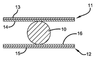
종래의 통신 케이블은 도면에서 부호 10으로 표시된다. 케이블(10)은 전통적으로 플라스틱 시스로 피복된 와이어의 코어를 포함한다. 이러한 케이블은 일반적으로 2500피트 이상의 케이블을 운반할 수 있는 롤에 보관된다.Conventional communication cables are indicated by
도 1에 도시된 바와 같이, 케이블의 시스보다 마찰 계수가 낮은 직물과 같은 유연한 재료로 케이블(10)을 감싸기 위해, 일반적으로 부호 11로 표시된 제1 시트 조립체 및 일반적으로 부호 12로 표시된 제2 시트 조립체가 제공된다. 시트 조립체(11)는 케이블(10)의 길이를 따라 길이 방향으로 연장되고, 접착 층(14)이 부착된 직물 층(13)을 포함한다. 유사하게, 시트 조립체(12)는 케이블(10)의 길이를 따라 길이 방향으로 연장되고, 접착 층(16)이 부착된 직물 층(15)을 포함한다.As shown in Fig. 1, in order to wrap the
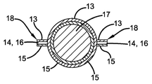
도 2에 도시된 직물로 감싸진 케이블(17)을 생성하기 위하여, 조립체(11 및 12)는 접착 층(14 및 16)이 서로 대향하며 종래의 케이블(10)이 층(14 및 16) 사이에 위치되도록 도 1에 도시된 바와 같이 위치된다. 그 후, 조립체(11 및 12)는 케이블(10)을 감싸며 접착 층(14 및 16)은 케이블(10)과 치합하여 감싸진 케이블(17)을 형성한다. 조립체(11 및 12)의 측방향 에지는 접착 층(14 및 16)의 측방향 에지가 서로 치합할 때 윙(18)을 형성한다. 윙(18)은 케이블(17)의 일반적인 정반대 측면으로부터 반경 방향 외측으로 연장된다. 이러한 윙(18)은 케이블(17)에 강도를 추가하는 경향이 있으며, 케이블을 도관으로 당기는 데 이용될 수 있다. 즉, 당김 장치는 케이블의 윙에 부착될 수 있거나 또는 이와 달리 이를 파지하여 케이블을 도관에 삽입할 수 있다.In order to create the fabric-wrapped
감싸진 케이블(17)은 시트 조립체(11 및 12)와 함께 케이블(10)을 길이 방향으로 이동시키고 접힘 스테이션을 제공함으로써 생성될 수 있다. 케이블(10) 및 조립체(11 및 12)가 해당 스테이션을 통과할 때, 조립체(11 및 12)는 이전에 설명된 바와 같이 케이블(10)을 감싼다. 이는 케이블의 제조 현장에서 수행될 수 있거나, 감싸진 케이블(17)이 도관에 설치될 현장에서 제공될 수 있다. 이런 경우, 케이블(10)의 롤 및 시트 조립체(11 및 12)의 롤은 그에 따른 케이블(17)이 도관에 설치될 때 케이블(10)을 감쌀 장치를 통해 제공되어 공급될 수 있다.The wrapped
케이블(10)을 감싸는 대안적인 방식은 도 4 및 5에 도시되어 있다. 여기에서, 제1 시트 조립체(21) 및 제2 시트 조립체(22)가 제공된다. 시트 조립체(11)는 직물 층(13)과 동일할 수 있는 직물 층(23)을 포함한다. 시트 조립체(23)는 또한 직물 층(23)의 측방향 주변에 위치된 2개의 작은 층(24)으로 형성되는 접착 층을 포함한다. 유사하게, 시트 조립체(22)는 직물 층(15)과 동일할 수 있는 직물 층(25)을 포함한다. 시트 조립체(22)는 또한 직물 층(25)의 측방향 주변에 위치된 2개의 작은 층(26)으로 형성되는 접착 층을 포함한다.An alternative way of wrapping the
도 5에 도시된 직물로 감싸진 케이블(17)을 생성하기 위하여, 조립체(21 및 22)는 도 4에 도시된 바와 같이 위치되고, 접착 층(24 및 26)은 서로 대향하며 케이블(10)은 시트 조립체(21 및 22) 사이에 위치된다. 그 후, 조립체(21 및 22)는 케이블(10)을 단단히 감싸고, 접착 층 부분(24)은 도 5에 도시된 바와 같이 접착 층 부분(26)과 치합하여 윙(28)을 형성한다. 시트 조립체(23, 25) 중 하나에만 접착 부분(24 또는 26)이 제공되는 경우, 도 5의 실시예는 케이블(17)을 만족스럽게 생성할 것으로 고려된다. 따라서, 나머지 접착 부분은 대향 시트 조립체에 직접 부착될 것이다. 어느 경우든, 도 5의 결과적인 평면도는 도 3과 동일하다. 결과적으로 직물로 감싸진 케이블(17)은 도 1-3의 실시예와 관련해서 설명된 바와 동일한 방식으로 제조될 수 있다.In order to create the
다른 케이블 감싸기 버전은 도 6-8에 도시되어 있다. 여기에서, 일반적으로 부호 30으로 표시되는 하나의 연속적인 직물 재료 시트는 접혀져서, 그의 단부에 작은 접착 층(34)을 갖는 제1 직물 층(33)을 형성하고, 그의 단부에 작은 접착 층(36)을 갖는 제2 직물 층(35)을 형성한다. 재료(30)가 제조될 때, 릴리스 시트(37)는 각 접착 층(34, 36)에 위치된다. 도 7에 도시된 직물로 감싸진 케이블(17)을 생성하고자 할 때, 케이블(10)은 접착 층(34 및 36) 사이의 개구를 통해 연장되어 층(33 및 35) 사이에 위치된다. 그 후, 릴리스 시트(37)는 접착 층(34, 36)으로부터 제거되고, 층(33, 35)은 케이블(10) 둘레에 조여져서 감겨진 케이블(17)을 형성하며 접착 층(34, 36)은 서로 부착되어 윙(38)을 형성한다.Another cable wrap version is shown in Figures 6-8. Here, one continuous sheet of fabric material, generally denoted by the
전술한 바를 고려하여, 감겨진 케이블을 생성하기 위해 개시된 임의의 옵션은 본 발명의 목적을 달성할 것이고 그렇지 않으면 기술을 실질적으로 개선할 것임이 명백해야 한다.In view of the foregoing, it should be apparent that any options disclosed to create a wound cable will achieve the object of the present invention and otherwise will substantially improve the technology.
Claims (13)
Applications Claiming Priority (5)
| Application Number | Priority Date | Filing Date | Title |
|---|---|---|---|
| US201862681744P | 2018-06-07 | 2018-06-07 | |
| US62/681,744 | 2018-06-07 | ||
| US16/429,229 US11342098B2 (en) | 2018-06-07 | 2019-06-03 | Cable with a fabric sleeve and its method of manufacture |
| US16/429,229 | 2019-06-03 | ||
| PCT/US2019/035315 WO2019236531A1 (en) | 2018-06-07 | 2019-06-04 | Cable with a fabric sleeve and its method of manufacture |
Publications (1)
| Publication Number | Publication Date |
|---|---|
| KR20210018824A true KR20210018824A (en) | 2021-02-18 |
Family
ID=68764152
Family Applications (1)
| Application Number | Title | Priority Date | Filing Date |
|---|---|---|---|
| KR1020207035269A KR20210018824A (en) | 2018-06-07 | 2019-06-04 | Cable with woven sleeve and method for manufacturing same |
Country Status (18)
| Country | Link |
|---|---|
| US (2) | US11342098B2 (en) |
| EP (1) | EP3791452A1 (en) |
| JP (1) | JP2021525997A (en) |
| KR (1) | KR20210018824A (en) |
| CN (1) | CN112166536A (en) |
| AU (1) | AU2019282135B2 (en) |
| BR (1) | BR112020024801A2 (en) |
| CA (1) | CA3101207A1 (en) |
| CL (1) | CL2020003183A1 (en) |
| CO (1) | CO2020015381A2 (en) |
| CR (1) | CR20200573A (en) |
| IL (1) | IL279171A (en) |
| MX (1) | MX2020013133A (en) |
| PE (1) | PE20210538A1 (en) |
| PH (1) | PH12020551924A1 (en) |
| SG (1) | SG11202011217SA (en) |
| WO (1) | WO2019236531A1 (en) |
| ZA (1) | ZA202007131B (en) |
Family Cites Families (21)
| Publication number | Priority date | Publication date | Assignee | Title |
|---|---|---|---|---|
| US4004362A (en) * | 1975-09-29 | 1977-01-25 | W. H. Brady Co. | Adhesive wire marker |
| US5278356A (en) * | 1990-06-08 | 1994-01-11 | Miller Terry Q | Hold-down tape for electrical cables |
| JPH117856A (en) * | 1997-06-16 | 1999-01-12 | Sumitomo Wiring Syst Ltd | Outer casing structure of wire harness with protecting material |
| DE19732958A1 (en) * | 1997-07-31 | 1999-02-04 | Coroplast Fritz Mueller Kg | Adhesive tape for wrapping elongated goods, such as cable sets, plastic profiles or the like. |
| US6262371B1 (en) | 1999-06-23 | 2001-07-17 | Marc Talon, Inc. | Method and apparatus for dividing a conduit into compartments |
| US20020098311A1 (en) * | 1999-09-02 | 2002-07-25 | Michael Lindner | Protective sheathing |
| US6398190B1 (en) * | 2000-10-30 | 2002-06-04 | Milliken & Company | Cable assembly and method |
| HUP0700413A2 (en) * | 2007-01-02 | 2008-09-29 | Gyoergy Beofsics | Device for passage date cables in wiring channels |
| US7799997B2 (en) * | 2007-04-27 | 2010-09-21 | Milliken & Company | Innerduct structure having increased flexibility |
| WO2010005461A1 (en) * | 2008-06-23 | 2010-01-14 | Tvc Communications, L.L.C. | Communications cable with fabric sleeve |
| US10177546B2 (en) * | 2008-06-23 | 2019-01-08 | Wesco Distribution, Inc. | Conduit divider in the form of a cable with fabric sleeve |
| EP2443633B1 (en) * | 2009-06-19 | 2017-09-13 | 3M Innovative Properties Company | Shielded electrical cable |
| CN203631172U (en) * | 2011-04-07 | 2014-06-04 | 3M创新有限公司 | High speed transmission cable |
| US9833024B2 (en) * | 2011-08-31 | 2017-12-05 | Luen Hing Textile (Zhong Shan) Co., Ltd. | Wire casing and method of making the same |
| JP2013258802A (en) * | 2012-06-11 | 2013-12-26 | Sumitomo Wiring Syst Ltd | Wire harness coating member, wire harness with coating member and attachment method for wire harness coating member |
| EP3005502B1 (en) * | 2013-05-28 | 2018-03-07 | Federal-Mogul Powertrain, Inc. | Wrapped textile sleeve with bonded closure mechanism and method of construction thereof |
| US10518511B2 (en) * | 2013-07-26 | 2019-12-31 | Federal-Mogul Powertrain Llc | Wrappable protective sleeve with closure and locating feature and methods of construction and use thereof |
| US20150340128A1 (en) * | 2014-05-23 | 2015-11-26 | Avago Technologies General Ip (Singapore) Pte. Ltd | Flame-retardant zipper sleeve for wrapping an optical fiber cable bundle or an electrical cable bundle and a method of making the zipper sleeve |
| US10407807B2 (en) * | 2014-09-24 | 2019-09-10 | Federal-Mogul Powertrain Llc | Textile sleeve with adhesive fixation layer and methods of construction and use thereof |
| JP6462513B2 (en) * | 2015-07-06 | 2019-01-30 | 古河電気工業株式会社 | Wire harness protection sheet, wire harness with sheet, and method of attaching the sheet to wire harness |
| CN107858112A (en) * | 2017-12-19 | 2018-03-30 | 浏阳湘冠胶粘科技有限公司 | The compound kraft paper gummed tape being layered for fireworks |
-
2019
- 2019-06-03 US US16/429,229 patent/US11342098B2/en active Active
- 2019-06-04 WO PCT/US2019/035315 patent/WO2019236531A1/en active Application Filing
- 2019-06-04 PE PE2020001933A patent/PE20210538A1/en unknown
- 2019-06-04 CR CR20200573A patent/CR20200573A/en unknown
- 2019-06-04 KR KR1020207035269A patent/KR20210018824A/en not_active IP Right Cessation
- 2019-06-04 AU AU2019282135A patent/AU2019282135B2/en active Active
- 2019-06-04 JP JP2020565848A patent/JP2021525997A/en active Pending
- 2019-06-04 CN CN201980035129.7A patent/CN112166536A/en active Pending
- 2019-06-04 EP EP19737283.2A patent/EP3791452A1/en active Pending
- 2019-06-04 BR BR112020024801-0A patent/BR112020024801A2/en unknown
- 2019-06-04 MX MX2020013133A patent/MX2020013133A/en unknown
- 2019-06-04 CA CA3101207A patent/CA3101207A1/en active Pending
- 2019-06-04 SG SG11202011217SA patent/SG11202011217SA/en unknown
-
2020
- 2020-11-11 PH PH12020551924A patent/PH12020551924A1/en unknown
- 2020-11-16 ZA ZA2020/07131A patent/ZA202007131B/en unknown
- 2020-12-03 IL IL279171A patent/IL279171A/en unknown
- 2020-12-07 CL CL2020003183A patent/CL2020003183A1/en unknown
- 2020-12-09 CO CONC2020/0015381A patent/CO2020015381A2/en unknown
-
2022
- 2022-04-25 US US17/728,186 patent/US20220246331A1/en active Pending
Also Published As
| Publication number | Publication date |
|---|---|
| BR112020024801A2 (en) | 2021-03-02 |
| CL2020003183A1 (en) | 2021-06-25 |
| JP2021525997A (en) | 2021-09-27 |
| WO2019236531A1 (en) | 2019-12-12 |
| PH12020551924A1 (en) | 2021-06-14 |
| CA3101207A1 (en) | 2019-12-12 |
| US11342098B2 (en) | 2022-05-24 |
| CO2020015381A2 (en) | 2020-12-21 |
| MX2020013133A (en) | 2021-02-18 |
| AU2019282135A1 (en) | 2020-12-10 |
| CR20200573A (en) | 2021-02-01 |
| AU2019282135B2 (en) | 2023-08-03 |
| US20190378636A1 (en) | 2019-12-12 |
| ZA202007131B (en) | 2021-10-27 |
| IL279171A (en) | 2021-01-31 |
| EP3791452A1 (en) | 2021-03-17 |
| CN112166536A (en) | 2021-01-01 |
| US20220246331A1 (en) | 2022-08-04 |
| PE20210538A1 (en) | 2021-03-17 |
| SG11202011217SA (en) | 2020-12-30 |
Similar Documents
| Publication | Publication Date | Title |
|---|---|---|
| US20230014038A1 (en) | Communications cable with fabric sleeve | |
| JP4236841B2 (en) | Method and apparatus for dividing a conduit into a plurality of compartments | |
| US20140353561A1 (en) | System and method for guiding a cable | |
| KR20210018824A (en) | Cable with woven sleeve and method for manufacturing same | |
| US10177546B2 (en) | Conduit divider in the form of a cable with fabric sleeve | |
| RU2780355C2 (en) | Cable in fabric tubular isolation and its manufacturing method | |
| KR20210019417A (en) | Method of manufacturing inner duct for conduit | |
| JP2006310066A (en) | Harness and manufacturing method for it | |
| JP2531929B2 (en) | Insulation pipe manufacturing method | |
| KR20210152477A (en) | Method and device for introducing cables into conduits | |
| JP5879072B2 (en) | Protective tube installation jig, protective tube, protective tube installation method, and protective tube manufacturing method | |
| JP2002354622A (en) | Cable protective pipe lead-in method | |
| JP5497122B2 (en) | Cable laying equipment | |
| JP2007041014A (en) | Structure and method of fixing optical cable | |
| JP2016031787A (en) | Wire/cable | |
| KR20120093631A (en) | Conductor insulation method for high voltage cable |
Legal Events
| Date | Code | Title | Description |
|---|---|---|---|
| AMND | Amendment | ||
| E902 | Notification of reason for refusal | ||
| E601 | Decision to refuse application | ||
| AMND | Amendment | ||
| X601 | Decision of rejection after re-examination |