KR20210000742A - Electrode assemblies - Google Patents
Electrode assemblies Download PDFInfo
- Publication number
- KR20210000742A KR20210000742A KR1020207037187A KR20207037187A KR20210000742A KR 20210000742 A KR20210000742 A KR 20210000742A KR 1020207037187 A KR1020207037187 A KR 1020207037187A KR 20207037187 A KR20207037187 A KR 20207037187A KR 20210000742 A KR20210000742 A KR 20210000742A
- Authority
- KR
- South Korea
- Prior art keywords
- weight
- electrode layer
- electrode assembly
- cathode
- anode
- Prior art date
Links
Images


Classifications
-
- H—ELECTRICITY
- H01—ELECTRIC ELEMENTS
- H01M—PROCESSES OR MEANS, e.g. BATTERIES, FOR THE DIRECT CONVERSION OF CHEMICAL ENERGY INTO ELECTRICAL ENERGY
- H01M10/00—Secondary cells; Manufacture thereof
- H01M10/05—Accumulators with non-aqueous electrolyte
- H01M10/052—Li-accumulators
- H01M10/0525—Rocking-chair batteries, i.e. batteries with lithium insertion or intercalation in both electrodes; Lithium-ion batteries
-
- H—ELECTRICITY
- H01—ELECTRIC ELEMENTS
- H01M—PROCESSES OR MEANS, e.g. BATTERIES, FOR THE DIRECT CONVERSION OF CHEMICAL ENERGY INTO ELECTRICAL ENERGY
- H01M10/00—Secondary cells; Manufacture thereof
- H01M10/05—Accumulators with non-aqueous electrolyte
- H01M10/052—Li-accumulators
-
- H—ELECTRICITY
- H01—ELECTRIC ELEMENTS
- H01M—PROCESSES OR MEANS, e.g. BATTERIES, FOR THE DIRECT CONVERSION OF CHEMICAL ENERGY INTO ELECTRICAL ENERGY
- H01M10/00—Secondary cells; Manufacture thereof
- H01M10/05—Accumulators with non-aqueous electrolyte
- H01M10/058—Construction or manufacture
-
- H01M2/162—
-
- H—ELECTRICITY
- H01—ELECTRIC ELEMENTS
- H01M—PROCESSES OR MEANS, e.g. BATTERIES, FOR THE DIRECT CONVERSION OF CHEMICAL ENERGY INTO ELECTRICAL ENERGY
- H01M4/00—Electrodes
- H01M4/02—Electrodes composed of, or comprising, active material
- H01M4/04—Processes of manufacture in general
- H01M4/0402—Methods of deposition of the material
- H01M4/0404—Methods of deposition of the material by coating on electrode collectors
-
- H—ELECTRICITY
- H01—ELECTRIC ELEMENTS
- H01M—PROCESSES OR MEANS, e.g. BATTERIES, FOR THE DIRECT CONVERSION OF CHEMICAL ENERGY INTO ELECTRICAL ENERGY
- H01M4/00—Electrodes
- H01M4/02—Electrodes composed of, or comprising, active material
- H01M4/04—Processes of manufacture in general
- H01M4/043—Processes of manufacture in general involving compressing or compaction
-
- H—ELECTRICITY
- H01—ELECTRIC ELEMENTS
- H01M—PROCESSES OR MEANS, e.g. BATTERIES, FOR THE DIRECT CONVERSION OF CHEMICAL ENERGY INTO ELECTRICAL ENERGY
- H01M4/00—Electrodes
- H01M4/02—Electrodes composed of, or comprising, active material
- H01M4/04—Processes of manufacture in general
- H01M4/0471—Processes of manufacture in general involving thermal treatment, e.g. firing, sintering, backing particulate active material, thermal decomposition, pyrolysis
-
- H—ELECTRICITY
- H01—ELECTRIC ELEMENTS
- H01M—PROCESSES OR MEANS, e.g. BATTERIES, FOR THE DIRECT CONVERSION OF CHEMICAL ENERGY INTO ELECTRICAL ENERGY
- H01M4/00—Electrodes
- H01M4/02—Electrodes composed of, or comprising, active material
- H01M4/13—Electrodes for accumulators with non-aqueous electrolyte, e.g. for lithium-accumulators; Processes of manufacture thereof
- H01M4/139—Processes of manufacture
-
- H—ELECTRICITY
- H01—ELECTRIC ELEMENTS
- H01M—PROCESSES OR MEANS, e.g. BATTERIES, FOR THE DIRECT CONVERSION OF CHEMICAL ENERGY INTO ELECTRICAL ENERGY
- H01M4/00—Electrodes
- H01M4/02—Electrodes composed of, or comprising, active material
- H01M4/62—Selection of inactive substances as ingredients for active masses, e.g. binders, fillers
- H01M4/621—Binders
- H01M4/622—Binders being polymers
-
- H—ELECTRICITY
- H01—ELECTRIC ELEMENTS
- H01M—PROCESSES OR MEANS, e.g. BATTERIES, FOR THE DIRECT CONVERSION OF CHEMICAL ENERGY INTO ELECTRICAL ENERGY
- H01M4/00—Electrodes
- H01M4/02—Electrodes composed of, or comprising, active material
- H01M4/62—Selection of inactive substances as ingredients for active masses, e.g. binders, fillers
- H01M4/624—Electric conductive fillers
- H01M4/625—Carbon or graphite
-
- H—ELECTRICITY
- H01—ELECTRIC ELEMENTS
- H01M—PROCESSES OR MEANS, e.g. BATTERIES, FOR THE DIRECT CONVERSION OF CHEMICAL ENERGY INTO ELECTRICAL ENERGY
- H01M4/00—Electrodes
- H01M4/02—Electrodes composed of, or comprising, active material
- H01M4/64—Carriers or collectors
- H01M4/66—Selection of materials
- H01M4/661—Metal or alloys, e.g. alloy coatings
-
- H—ELECTRICITY
- H01—ELECTRIC ELEMENTS
- H01M—PROCESSES OR MEANS, e.g. BATTERIES, FOR THE DIRECT CONVERSION OF CHEMICAL ENERGY INTO ELECTRICAL ENERGY
- H01M50/00—Constructional details or processes of manufacture of the non-active parts of electrochemical cells other than fuel cells, e.g. hybrid cells
- H01M50/40—Separators; Membranes; Diaphragms; Spacing elements inside cells
- H01M50/409—Separators, membranes or diaphragms characterised by the material
- H01M50/411—Organic material
- H01M50/414—Synthetic resins, e.g. thermoplastics or thermosetting resins
-
- H—ELECTRICITY
- H01—ELECTRIC ELEMENTS
- H01M—PROCESSES OR MEANS, e.g. BATTERIES, FOR THE DIRECT CONVERSION OF CHEMICAL ENERGY INTO ELECTRICAL ENERGY
- H01M50/00—Constructional details or processes of manufacture of the non-active parts of electrochemical cells other than fuel cells, e.g. hybrid cells
- H01M50/40—Separators; Membranes; Diaphragms; Spacing elements inside cells
- H01M50/409—Separators, membranes or diaphragms characterised by the material
- H01M50/44—Fibrous material
-
- H—ELECTRICITY
- H01—ELECTRIC ELEMENTS
- H01M—PROCESSES OR MEANS, e.g. BATTERIES, FOR THE DIRECT CONVERSION OF CHEMICAL ENERGY INTO ELECTRICAL ENERGY
- H01M50/00—Constructional details or processes of manufacture of the non-active parts of electrochemical cells other than fuel cells, e.g. hybrid cells
- H01M50/40—Separators; Membranes; Diaphragms; Spacing elements inside cells
- H01M50/409—Separators, membranes or diaphragms characterised by the material
- H01M50/449—Separators, membranes or diaphragms characterised by the material having a layered structure
-
- H—ELECTRICITY
- H01—ELECTRIC ELEMENTS
- H01M—PROCESSES OR MEANS, e.g. BATTERIES, FOR THE DIRECT CONVERSION OF CHEMICAL ENERGY INTO ELECTRICAL ENERGY
- H01M50/00—Constructional details or processes of manufacture of the non-active parts of electrochemical cells other than fuel cells, e.g. hybrid cells
- H01M50/40—Separators; Membranes; Diaphragms; Spacing elements inside cells
- H01M50/489—Separators, membranes, diaphragms or spacing elements inside the cells, characterised by their physical properties, e.g. swelling degree, hydrophilicity or shut down properties
- H01M50/491—Porosity
-
- H—ELECTRICITY
- H01—ELECTRIC ELEMENTS
- H01M—PROCESSES OR MEANS, e.g. BATTERIES, FOR THE DIRECT CONVERSION OF CHEMICAL ENERGY INTO ELECTRICAL ENERGY
- H01M4/00—Electrodes
- H01M4/02—Electrodes composed of, or comprising, active material
- H01M2004/021—Physical characteristics, e.g. porosity, surface area
-
- H—ELECTRICITY
- H01—ELECTRIC ELEMENTS
- H01M—PROCESSES OR MEANS, e.g. BATTERIES, FOR THE DIRECT CONVERSION OF CHEMICAL ENERGY INTO ELECTRICAL ENERGY
- H01M4/00—Electrodes
- H01M4/02—Electrodes composed of, or comprising, active material
- H01M4/62—Selection of inactive substances as ingredients for active masses, e.g. binders, fillers
- H01M4/621—Binders
- H01M4/622—Binders being polymers
- H01M4/623—Binders being polymers fluorinated polymers
-
- Y—GENERAL TAGGING OF NEW TECHNOLOGICAL DEVELOPMENTS; GENERAL TAGGING OF CROSS-SECTIONAL TECHNOLOGIES SPANNING OVER SEVERAL SECTIONS OF THE IPC; TECHNICAL SUBJECTS COVERED BY FORMER USPC CROSS-REFERENCE ART COLLECTIONS [XRACs] AND DIGESTS
- Y02—TECHNOLOGIES OR APPLICATIONS FOR MITIGATION OR ADAPTATION AGAINST CLIMATE CHANGE
- Y02E—REDUCTION OF GREENHOUSE GAS [GHG] EMISSIONS, RELATED TO ENERGY GENERATION, TRANSMISSION OR DISTRIBUTION
- Y02E60/00—Enabling technologies; Technologies with a potential or indirect contribution to GHG emissions mitigation
- Y02E60/10—Energy storage using batteries
-
- Y—GENERAL TAGGING OF NEW TECHNOLOGICAL DEVELOPMENTS; GENERAL TAGGING OF CROSS-SECTIONAL TECHNOLOGIES SPANNING OVER SEVERAL SECTIONS OF THE IPC; TECHNICAL SUBJECTS COVERED BY FORMER USPC CROSS-REFERENCE ART COLLECTIONS [XRACs] AND DIGESTS
- Y02—TECHNOLOGIES OR APPLICATIONS FOR MITIGATION OR ADAPTATION AGAINST CLIMATE CHANGE
- Y02P—CLIMATE CHANGE MITIGATION TECHNOLOGIES IN THE PRODUCTION OR PROCESSING OF GOODS
- Y02P70/00—Climate change mitigation technologies in the production process for final industrial or consumer products
- Y02P70/50—Manufacturing or production processes characterised by the final manufactured product
-
- Y—GENERAL TAGGING OF NEW TECHNOLOGICAL DEVELOPMENTS; GENERAL TAGGING OF CROSS-SECTIONAL TECHNOLOGIES SPANNING OVER SEVERAL SECTIONS OF THE IPC; TECHNICAL SUBJECTS COVERED BY FORMER USPC CROSS-REFERENCE ART COLLECTIONS [XRACs] AND DIGESTS
- Y02—TECHNOLOGIES OR APPLICATIONS FOR MITIGATION OR ADAPTATION AGAINST CLIMATE CHANGE
- Y02T—CLIMATE CHANGE MITIGATION TECHNOLOGIES RELATED TO TRANSPORTATION
- Y02T10/00—Road transport of goods or passengers
- Y02T10/60—Other road transportation technologies with climate change mitigation effect
- Y02T10/70—Energy storage systems for electromobility, e.g. batteries
Landscapes
- Chemical & Material Sciences (AREA)
- Chemical Kinetics & Catalysis (AREA)
- Electrochemistry (AREA)
- General Chemical & Material Sciences (AREA)
- Engineering & Computer Science (AREA)
- Manufacturing & Machinery (AREA)
- Materials Engineering (AREA)
- Battery Electrode And Active Subsutance (AREA)
- Secondary Cells (AREA)
- Inorganic Chemistry (AREA)
- Cell Electrode Carriers And Collectors (AREA)
- Cell Separators (AREA)
Abstract
본 발명은 하나 이상의 캐소드, 하나 이상의 애노드, 하나 이상의 캐소드 및 하나 이상의 애노드와 하나 이상의 캐소드 사이에 삽입된 하나 이상의 세퍼레이터를 포함하는 리튬 이온 전지의 전극 조립체를 구비하고, 상기 전극 조립체 수분 함량은, 상기 전극 조립체의 총 중량을 기준으로, 20 중량ppm 미만이다. The present invention includes an electrode assembly of a lithium ion battery comprising at least one cathode, at least one anode, at least one cathode, and at least one separator inserted between at least one anode and at least one cathode, wherein the electrode assembly moisture content is Based on the total weight of the electrode assembly, it is less than 20 ppm by weight.
Description
본 발명은 전지 분야에 관한 것이다. 특히 본 발명은 리튬 이온 전지의 전극 조립체를 건조하는 방법 및 본 명세서에 개시된 방법에 의해 제조된 전극 조립체에 관한 것이다. The present invention relates to the field of batteries. In particular, the present invention relates to a method of drying an electrode assembly of a lithium ion battery and an electrode assembly manufactured by the method disclosed herein.
리튬이온전지(LIB)는 지난 20년간 핸드폰 및 랩탑 컴퓨터와 같은 휴대용 전자 장치의 광범위한 응용 분야에서 많은 주목을 받아왔다. 전기자동차(EV) 및 그리드 에너지 저장장치(grid energy storage) 시장의 급속한 발전으로 인해, 고성능, 저비용의 LIB는 현재 대규모 에너지 저장 장치에 대한 유망한 옵션 중 하나이다. Lithium-ion batteries (LIBs) have attracted much attention over the past 20 years in a wide range of applications in portable electronic devices such as cell phones and laptop computers. Due to the rapid development of the electric vehicle (EV) and grid energy storage markets, high-performance, low-cost LIB is currently one of the promising options for large-scale energy storage devices.
현재, 전극은 활성 전지 전극 물질, 도전제, 바인더 물질의 분말을 적절한 용매에 분산시킴으로써 제조된다. 분산액이 구리 또는 알루미늄 금속 호일과 같은 집전체 상에 코팅될 수 있고, 그 후 승온에서 건조시켜 용매를 제거한다. 이어서 캐소드 시트 및 애노드 시트가 캐소드와 애노드를 분리하는 세퍼레이터와 적층되거나 압연(rolled)되어 전지를 형성한다. Currently, electrodes are manufactured by dispersing powders of an active battery electrode material, a conductive agent, and a binder material in an appropriate solvent. The dispersion may be coated on a current collector such as copper or aluminum metal foil, and then dried at elevated temperature to remove the solvent. Subsequently, the cathode sheet and the anode sheet are stacked or rolled with a separator separating the cathode and the anode to form a battery.
리튬 이온 전지 제조 공정은 수분에 민감하다. 수분 함량이 높은 전지는 전기화학적 성능의 심각한 감쇄를 초래하고, 전지의 안정성에 영향을 끼친다. 그러므로, LIB의 생산 공정을 위해 주변 습도를 엄격하게 제어해야 한다. 대부분의 LIB는 습도가 1% 미만인 환경에서 제조된다. 그러나 엄격한 무-수분 공정 때문에 상당한 비용이 발생된다. 전극 조립체의 수분 민감성 문제를 해결하기 위해선, 전해질을 채우기 전에 전극 조립체를 건조하여 전지의 수분 함량을 줄이는 것이 중요하다. The lithium ion battery manufacturing process is sensitive to moisture. A battery with a high moisture content causes a significant decrease in electrochemical performance and affects the stability of the battery. Therefore, it is necessary to strictly control the ambient humidity for the production process of LIB. Most LIBs are manufactured in environments with less than 1% humidity. However, significant costs are incurred due to the rigorous moisture-free process. In order to solve the moisture sensitivity problem of the electrode assembly, it is important to dry the electrode assembly before filling the electrolyte to reduce the moisture content of the battery.
중국 특허 제 104142045 B 호에는 LIB의 전극 조립체를 건조하는 방법이 기재되어있다. 이 방법은 진공 하에 30-100℃의 온도에서 전극 조립체를 가열하는 단계; 오븐에 건조 공기 또는 비활성 가스를 충전하는 단계; 이 두 단계를 1-10회 반복하는 단계를 포함한다. 이 방법은 430.5 중량ppm과 488.1 중량ppm 사이의 수분 함량을 갖는 전극 조립체를 제공한다.Chinese Patent No. 104142045 B describes a method of drying the electrode assembly of LIB. The method includes heating the electrode assembly at a temperature of 30-100° C. under vacuum; Filling the oven with dry air or an inert gas; It involves repeating these two steps 1-10 times. This method provides an electrode assembly having a moisture content between 430.5 ppm by weight and 488.1 ppm by weight.
중국 특허 출원 제 105115250 A 호에는 LIB의 전극 조립체를 건조하는 방법이 기재되어있다. 이 방법은 85±5℃의 온도에서 진공 하에 전극 조립체를 가열하는 단계; 오븐에 고온의 건조한 질소 가스를 충전하는 단계; 이 두 단계를 10-20회 반복하는 단계를 포함한다. 이 방법은 수분 함량이 200 중량ppm 미만인 전극 조립체를 제공한다.Chinese Patent Application No. 105115250 A describes a method of drying the electrode assembly of LIB. The method includes heating the electrode assembly under vacuum at a temperature of 85±5° C.; Filling the oven with hot dry nitrogen gas; It involves repeating these two steps 10-20 times. This method provides an electrode assembly having a moisture content of less than 200 ppm by weight.
중국 특허 제 102735023 B 호에는 LIB의 전극 조립체를 건조하는 방법이 기재되어있다. 이 방법은 진공 하에 20 내지 70℃의 온도에서 전극 조립체를 가열하는 단계; 오븐에 건조 공기 또는 질소 가스를 충전하는 단계; 이 두 단계를 5-50회 반복하는 단계를 포함한다. 이 방법은 110.1 중량ppm과 137.2 중량ppm 사이의 수분 함량을 갖는 전극 조립체를 제공한다.Chinese Patent No. 102735023 B describes a method of drying the electrode assembly of LIB. The method includes heating the electrode assembly at a temperature of 20 to 70° C. under vacuum; Filling the oven with dry air or nitrogen gas; It involves repeating these two steps 5-50 times. This method provides an electrode assembly having a moisture content between 110.1 ppm by weight and 137.2 ppm by weight.
중국 특허 제 103344097 B 호에는 LIB의 전극 조립체를 건조하는 방법이 기재되어있다. 이 방법은 진공 하에 75 내지 85℃의 온도에서 전극 조립체를 가열하는 단계; 오븐에 비산화성 가스를 충전하는 단계; 전극 조립체를 75 내지 85℃로 가열하는 단계; 전극 조립체를 다시 진공 건조하는 단계를 포함한다. 그러나, 이 방법은 건조 공정을 평가하기 위한, 건조된 전극 조립체의 수분 함량을 제공하지 못한다.Chinese Patent No. 103344097 B describes a method of drying the electrode assembly of LIB. The method includes heating the electrode assembly at a temperature of 75 to 85° C. under vacuum; Filling the oven with a non-oxidizing gas; Heating the electrode assembly to 75 to 85°C; And vacuum drying the electrode assembly again. However, this method does not provide the moisture content of the dried electrode assembly for evaluating the drying process.
기존의 방법에 의해 건조된 전극 조립체의 수분 함량은 100 중량ppm 내지 수백 중량ppm 범위이며, 이는 LIB의 사이클 안정성 및 방전 성능(rate capability)에 영향을 미칠 수 있다. 상기 내용의 관점에서, 낮은 수분 함량을 갖는 전극 조립체가 항상 필요하다.The moisture content of the electrode assembly dried by the conventional method is in the range of 100 ppm by weight to several hundred ppm by weight, which may affect the cycle stability and rate capability of the LIB. In view of the above, there is always a need for an electrode assembly having a low moisture content.
전술한 필요성은 본 명세서에 개시된 다양한 측면 및 실시예에 의해 충족된다. The foregoing needs are met by the various aspects and embodiments disclosed herein.
일 측면에서, 본 발명은 하나 이상의 애노드, 하나 이상의 캐소드, 및 하나 이상의 애노드와 하나 이상의 캐소드 사이에 삽입된 하나 이상의 세퍼레이터를 포함하는 비수성 전해질 2차 전지용 전극 조립체를 구비하며, 상기 전극 조립체의 수분 함량은, 상기 전극 조립체의 총 중량을 기준으로, 20 중량ppm 미만이다.In one aspect, the present invention includes an electrode assembly for a non-aqueous electrolyte secondary battery comprising at least one anode, at least one cathode, and at least one separator inserted between at least one anode and at least one cathode, and the moisture of the electrode assembly The content is less than 20 ppm by weight, based on the total weight of the electrode assembly.
특정 실시예에서, 하나 이상의 캐소드는 캐소드 집전체, 및 캐소드 물질, 바인더 물질 및 도전제를 포함하는 캐소드 전극층을 포함하고, 하나 이상의 애노드는 애노드 집전체, 및 애노드 물질, 바인더 물질 및 도전제를 포함하는 애노드 전극층을 포함한다. 상기 캐소드 전극층 및 애노드 전극층 각각은 독립적으로 전극층의 총 부피를 기준으로, 40% 미만, 35% 미만, 33% 미만, 30% 미만, 25% 미만, 20% 미만, 18% 미만, 15% 미만, 13% 미만, 10% 미만 또는 8% 미만의 공극 부피를 가진다.In certain embodiments, at least one cathode comprises a cathode current collector, and a cathode electrode layer comprising a cathode material, a binder material, and a conductive agent, and at least one anode comprises an anode current collector, and an anode material, a binder material, and a conductive agent. It includes an anode electrode layer. Each of the cathode electrode layer and the anode electrode layer is independently less than 40%, less than 35%, less than 33%, less than 30%, less than 25%, less than 20%, less than 18%, less than 15%, based on the total volume of the electrode layer, It has a void volume of less than 13%, less than 10% or less than 8%.
일부 실시예에서, 캐소드 전극층 및 애노드 전극층 각각의 밀도는 독립적으로 약 1.0g/cm3 내지 약 6.5g/cm3 또는 약 1.0g/cm3 내지 약 3.0g/cm3이다.In some embodiments, the density of each of the cathode electrode layer and the anode electrode layer is independently about 1.0 g/cm 3 to about 6.5 g/cm 3 or about 1.0 g/cm 3 to about 3.0 g/cm 3 .
특정 실시예에서, 캐소드 전극층 및 애노드 전극층 각각의 두께는 독립적으로 약 1.0㎛ 내지 약 40㎛ 또는 약 1.0㎛ 내지 약 25㎛이다. In certain embodiments, the thickness of each of the cathode electrode layer and the anode electrode layer is independently about 1.0 μm to about 40 μm or about 1.0 μm to about 25 μm.
일부 실시예에서, 하나 이상의 세퍼레이터는 폴리올레핀, 폴리에틸렌, 고밀도 폴리에틸렌, 선형 저밀도 폴리에틸렌, 저밀도 폴리에틸렌, 초고분자량 폴리에틸렌, 폴리프로필렌, 폴리프로필렌/폴리에틸렌 공중합체, 폴리부틸렌, 폴리펜텐, 폴리아세탈, 폴리아미드, 폴리카보네이트, 폴리이미드, 폴리에테르에테르케톤, 폴리설폰, 폴리페닐렌 옥시드, 폴리페닐렌 설파이드, 폴리아크릴로니트릴, 폴리플루오르화비닐리덴, 폴리옥시메틸렌, 폴리비닐 피롤리돈, 폴리에스테르, 폴리에틸렌 테레프탈레이트, 폴리부틸렌 테레프탈레이트, 폴리에틸렌 나프탈렌, 폴리부틸렌 나프탈레이트 및 이들의 조합으로 구성된 군으로부터 선택된 폴리머 섬유로부터 만들어진다. In some embodiments, the one or more separators are polyolefin, polyethylene, high density polyethylene, linear low density polyethylene, low density polyethylene, ultra high molecular weight polyethylene, polypropylene, polypropylene/polyethylene copolymer, polybutylene, polypentene, polyacetal, polyamide, Polycarbonate, polyimide, polyetheretherketone, polysulfone, polyphenylene oxide, polyphenylene sulfide, polyacrylonitrile, polyvinylidene fluoride, polyoxymethylene, polyvinyl pyrrolidone, polyester, polyethylene It is made from polymer fibers selected from the group consisting of terephthalate, polybutylene terephthalate, polyethylene naphthalene, polybutylene naphthalate, and combinations thereof.
특정 실시예에서, 세퍼레이터의 두께는 약 1.0㎛ 내지 약 40㎛ 또는 약 1.0㎛ 내지 약 25㎛이다.In certain embodiments, the thickness of the separator is about 1.0 μm to about 40 μm or about 1.0 μm to about 25 μm.
일부 실시예에서, 캐소드 전극층 및 애노드 전극층의 각 바인더 물질은 스티렌-부타디엔 고무, 아크릴화 스티렌-부타디엔 고무, 아크릴로니트릴 공중합체, 아크릴로니트릴-부타디엔 고무, 니트릴 부타디엔 고무, 아크릴로니트릴-스티렌-부타디엔 공중합체, 아크릴 고무, 부틸 고무, 플루오린 고무, 폴리테트라플루오로에틸렌, 폴리에틸렌, 폴리프로필렌, 에틸렌/프로필렌 공중합체, 폴리부타디엔, 폴리에틸렌 옥시드, 클로로설폰화 폴리에틸렌, 폴리비닐피롤리돈, 폴리비닐피리딘, 폴리비닐 알코올, 폴리비닐 아세테이트, 폴리에피클로로하이드린, 폴리포스파젠, 폴리아크릴로니트릴, 폴리스티렌, 라텍스, 아크릴 수지, 페놀수지, 에폭시 수지, 카복시메틸셀룰로오스, 하이드록시프로필 셀룰로오스, 셀룰로오스 아세테이트, 셀룰로오스 아세테이트 부티레이트, 셀룰로오스 아세테이트 프로피오네이트, 시아노에틸셀룰로오스, 시아노에틸수크로스, 폴리에스테르, 폴리아미드, 폴리에테르, 폴리이미드, 폴리카복실레이트, 폴리카복시산, 폴리아크릴산, 폴리아크릴레이트, 폴리메타크릴산, 폴리메타크릴레이트, 폴리아크릴아미드, 폴리우레탄, 플루오르화 폴리머, 염소화 폴리머, 알긴산 염, 폴리비닐리덴 플루오라이드, 폴리(비닐리덴 플루오라이드)-헥사플루오로프로펜 및 이들의 조합으로 구성된 군으로부터 선택된다. In some embodiments, each binder material of the cathode electrode layer and the anode electrode layer is styrene-butadiene rubber, acrylated styrene-butadiene rubber, acrylonitrile copolymer, acrylonitrile-butadiene rubber, nitrile butadiene rubber, acrylonitrile-styrene-butadiene. Copolymer, acrylic rubber, butyl rubber, fluorine rubber, polytetrafluoroethylene, polyethylene, polypropylene, ethylene/propylene copolymer, polybutadiene, polyethylene oxide, chlorosulfonated polyethylene, polyvinylpyrrolidone, polyvinyl Pyridine, polyvinyl alcohol, polyvinyl acetate, polyepichlorohydrin, polyphosphazene, polyacrylonitrile, polystyrene, latex, acrylic resin, phenolic resin, epoxy resin, carboxymethylcellulose, hydroxypropyl cellulose, cellulose acetate, Cellulose acetate butyrate, cellulose acetate propionate, cyanoethylcellulose, cyanoethyl sucrose, polyester, polyamide, polyether, polyimide, polycarboxylate, polycarboxylic acid, polyacrylic acid, polyacrylate, polymetha Composed of acrylic acid, polymethacrylate, polyacrylamide, polyurethane, fluorinated polymer, chlorinated polymer, alginic acid salt, polyvinylidene fluoride, poly(vinylidene fluoride)-hexafluoropropene, and combinations thereof Is selected from the group.
특정 실시예에서, 캐소드 전극층의 바인더 물질 및 애노드 전극층의 바인더 물질 각각은 전극층의 총 중량을 기준으로, 2 중량% 내지 10 중량%의 양으로 독립적으로 존재한다.In a specific embodiment, each of the binder material of the cathode electrode layer and the binder material of the anode electrode layer is independently present in an amount of 2% to 10% by weight, based on the total weight of the electrode layer.
일부 실시예에서, 캐소드 물질은 LiCoO2, LiNiO2, LiNixMnyO2, Li1+zNixMnyCo1-x-yO2, LiNixCoyAlzO2, LiV2O5, LiTiS2, LiMoS2, LiMnO2, LiCrO2, LiMn2O4, LiFeO2, LiFePO4, LiNi0.5Mn1.5O4, LiNi0.4Mn1.6O4 및 이들의 조합으로 구성된 군으로부터 선택되고, 각 x는 독립적으로 0.3 내지 0.8, 각 y는 독립적으로 0.1 내지 0.45, 각 z는 독립적으로 0 내지 0.2이다. In some embodiments, the cathode material is LiCoO 2 , LiNiO 2 , LiNi x Mn y O 2 , Li 1+z Ni x Mn y Co 1-xy O 2 , LiNi x Co y Al z O 2 , LiV 2 O 5 , LiTiS 2 , LiMoS 2 , LiMnO 2 , LiCrO 2 , LiMn 2 O 4 , LiFeO 2 , LiFePO 4 , LiNi 0.5 Mn 1.5 O 4 , LiNi 0.4 Mn 1.6 O 4 and selected from the group consisting of a combination thereof, each x is independently 0.3 to 0.8, each y is independently 0.1 to 0.45, each z is independently 0 to 0.2 to be.
특정 실시예에서, 캐소드 전극층 및 애노드 전극층 내의 각각의 도전제는 탄소, 카본 블랙, 흑연, 팽창 흑연, 그래핀, 그래핀 나노 플레이트렛(graphene nanoplatelets), 탄소 섬유, 탄소 나노 섬유, 흑연화 탄소 조각(graphitized carbon flake), 탄소 튜브, 탄소 나노 튜브, 활성탄(activated carbon), 메조포러스 탄소(mesoporous carbon) 및 이들의 조합으로 구성된 군으로부터 독립적으로 선택된다. In a specific embodiment, each conductive agent in the cathode electrode layer and the anode electrode layer is carbon, carbon black, graphite, expanded graphite, graphene, graphene nanoplatelets, carbon fibers, carbon nanofibers, graphitized carbon fragments. (graphitized carbon flake), carbon tube, carbon nanotube, activated carbon (activated carbon), mesoporous carbon (mesoporous carbon), and are independently selected from the group consisting of a combination thereof.
일부 실시예에서, 캐소드 전극층 및 애노드 전극층의 각각의 도전제는 전극층의 총 중량을 기준으로, 2 중량% 내지 10 중량%의 양으로 독립적으로 존재한다.In some embodiments, each conductive agent in the cathode electrode layer and the anode electrode layer is independently present in an amount of 2% to 10% by weight, based on the total weight of the electrode layer.
특정 실시예에서, 애노드 물질은 천연 흑연 미립자(natural graphite particulate), 합성 흑연 미립자(synthetic graphite particulate), Sn 미립자, Li4Ti5O12 미립자, Si 미립자, Si-C 복합 미립자 및 이들의 조합으로 구성된 군으로부터 선택된다. In certain embodiments, the anode material is a natural graphite particulate, synthetic graphite particulate, Sn particulate, Li 4 Ti 5 O 12 particulate, Si particulate, Si-C composite particulate, and combinations thereof. It is selected from the group consisting of.
일부 실시예에서, 하나 이상의 캐소드의 집전체 및 하나 이상의 애노드의 집전체 각각은 독립적으로 스테인리스 스틸, 티타늄, 니켈, 알루미늄, 구리 또는 전기 전도성 수지이다. In some embodiments, each of the current collectors of the at least one cathode and the current collectors of the at least one anode is independently stainless steel, titanium, nickel, aluminum, copper, or an electrically conductive resin.
특정 실시예에서, 하나 이상의 캐소드의 집전체는 알루미늄 박막이고, 하나 이상의 애노드의 집전체는 구리 박막이다.In certain embodiments, the current collector of at least one cathode is a thin film of aluminum and the current collector of at least one anode is a thin film of copper.
일부 실시예에서, 전극 조립체 내의 하나 이상의 애노드 및 하나 이상의 캐소드는, 하나 이상의 애노드와 하나 이상의 캐소드의 총 중량을 기준으로, 20 중량ppm 미만의 수분 함량을 갖는다. In some embodiments, the at least one anode and at least one cathode in the electrode assembly has a moisture content of less than 20 ppm by weight, based on the total weight of the at least one anode and at least one cathode.
특정 실시예에서, 전극 조립체 내의 하나 이상의 세퍼레이터는 하나 이상의 세퍼레이터의 총 중량을 기준으로, 20 중량ppm 미만의 수분 함량을 갖는다.In certain embodiments, the one or more separators in the electrode assembly have a moisture content of less than 20 ppm by weight, based on the total weight of the one or more separators.
본 발명의 다른 측면은, 본 명세서에 개시된 방법에 의해 제조된 전극 조립체를 포함하는 리튬 전지를 제공한다.Another aspect of the present invention provides a lithium battery including an electrode assembly manufactured by the method disclosed herein.
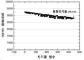
도1은 실시예 2에 기술된 방법에 의해 제조된 전극 조립체를 포함하는 전기화학전지의 사이클링 성능을 도시한 것이다.
도2은 실시예 4에 기술된 방법에 의해 제조된 전극 조립체를 포함하는 전기화학전지의 사이클링 성능을 도시한 것이다.
도3은 실시예 6에 기술된 방법에 의해 제조된 전극 조립체를 포함하는 전기화학전지의 사이클링 성능을 도시한 것이다.1 shows the cycling performance of an electrochemical cell including an electrode assembly prepared by the method described in Example 2.
FIG. 2 shows the cycling performance of an electrochemical cell including an electrode assembly manufactured by the method described in Example 4. FIG.
3 shows the cycling performance of an electrochemical cell including an electrode assembly manufactured by the method described in Example 6.
본 발명은 하나 이상의 애노드, 하나 이상의 캐소드 및 하나 이상의 애노드와 하나 이상의 캐소드 사이에 삽입된 하나 이상의 세퍼레이터를 포함하는 비수성 전해질 이차 전지용 전극 조립체를 구비하며, 전극 조립체의 수분 함량은 전극 조립체의 총 중량을 기준으로, 20 중량ppm 미만이다.The present invention includes an electrode assembly for a non-aqueous electrolyte secondary battery including at least one anode, at least one cathode, and at least one separator inserted between at least one anode and at least one cathode, wherein the moisture content of the electrode assembly is the total weight of the electrode assembly Based on, it is less than 20 ppm by weight.
"전극"이라는 용어는 "캐소드" 또는 "애노드"를 의미한다. The term "electrode" means "cathode" or "anode".
"양극"이라는 용어는 캐소드와 호환하여 사용된다. 마찬가지로, "음극"이라는 용어는 애노드와 호환하여 사용된다.The term "anode" is used interchangeably with the cathode. Likewise, the term "cathode" is used interchangeably with the anode.
"공극 부피"라는 용어는 전극층 내의 고체 물질 사이의 공간의 부피를 의미한다. 공극 부피가 클수록 전극층은 전해질을 많이 보유하게 된다.The term "void volume" means the volume of spaces between solid materials in the electrode layer. The larger the pore volume, the more electrolyte the electrode layer will hold.
"바인더 물질"이라는 용어는 전극 물질 및 도전제를 제 위치에 고정하는데 사용될 수 있는 화학물질 또는 물질을 의미한다. The term "binder material" refers to a chemical or material that can be used to hold the electrode material and conductive agent in place.
"수계 바인더 물질"이라는 용어는 수성 또는 수화 바인더 물질 폴리머를 의미한다. 수계 바인더 물질의 예로 스티렌-부타디엔 고무, 아크릴화 스티렌-부타디엔 고무, 아크릴로니트릴-부타디엔 고무, 아크릴 고무, 부틸 고무, 불소 고무, 폴리테트라플루오로에틸렌, 폴리에틸렌, 폴리프로필렌, 에틸렌/프로필렌 공중합체, 폴리부타디엔, 폴리에틸렌 옥시드, 폴리비닐피롤리돈, 폴리에피클로로하이드린, 폴리포스파젠, 폴리아크릴로니트릴, 폴리스티렌, 에틸렌/프로필렌/다이엔 공중합체, 폴리비닐피리딘, 클로로설포네이트 폴리에틸렌, 라텍스, 폴리에스테르 수지, 아크릴 수지, 페놀 수지, 에폭시 수지, 폴리비닐 알코올, 카복시메틸 셀룰로오스, 하이드록시프로필 셀룰로오스 및 이들의 조합을 포함하지만, 이에 한정되는 것은 아니다. The term "aqueous binder material" refers to an aqueous or hydrated binder material polymer. Examples of water-based binder materials include styrene-butadiene rubber, acrylated styrene-butadiene rubber, acrylonitrile-butadiene rubber, acrylic rubber, butyl rubber, fluorine rubber, polytetrafluoroethylene, polyethylene, polypropylene, ethylene/propylene copolymer, poly Butadiene, polyethylene oxide, polyvinylpyrrolidone, polyepichlorohydrin, polyphosphazene, polyacrylonitrile, polystyrene, ethylene/propylene/diene copolymer, polyvinylpyridine, chlorosulfonate polyethylene, latex, poly Ester resin, acrylic resin, phenol resin, epoxy resin, polyvinyl alcohol, carboxymethyl cellulose, hydroxypropyl cellulose, and combinations thereof, but are not limited thereto.
"유기계 바인더 물질"라는 용어는 유기 용매, 특히 N-메틸-2-피롤리돈(NMP)에 용해되거나 또는 분산되는 바인더 물질을 의미한다. 유기계 바인더 물질의 예로 폴리테트라플루오로에틸렌(PTFE), 퍼플루오로알콕시 폴리머(PFA), 폴리비닐리덴 플루오라이드(PVDF), 테트라플루오로에틸렌(TFE) 및 헥사플루오로프로필렌(HFP)의 공중합체, 불소화 에틸렌 프로필렌(FEP)의 공중합체, 테트라플루오로에틸렌, 헥사플루오로프로필렌 및 비닐리덴 플루오라이드의 터폴리머 및 이들의 조합을 포함하지만, 이에 한정되는 것은 아니다.The term "organic binder material" refers to a binder material that is dissolved or dispersed in an organic solvent, in particular N-methyl-2-pyrrolidone (NMP). Examples of organic binder materials are copolymers of polytetrafluoroethylene (PTFE), perfluoroalkoxy polymer (PFA), polyvinylidene fluoride (PVDF), tetrafluoroethylene (TFE) and hexafluoropropylene (HFP) , Copolymers of fluorinated ethylene propylene (FEP), terpolymers of tetrafluoroethylene, hexafluoropropylene and vinylidene fluoride, and combinations thereof, but are not limited thereto.
"집전체"라는 용어는 2차 전지를 방전 또는 충전하는 동안 전극에 전류가 흐르는 것을 유지하기 위해, 전극 물질 및 화학적으로 비활성인 고전자 전도체를 코팅하기 위한 지지체를 의미한다.The term "current collector" means a support for coating an electrode material and a chemically inert high electron conductor in order to keep current flowing through the electrode while discharging or charging the secondary battery.
"도전제"라는 용어는 화학적으로 비활성이고, 양호한 전기 전도성을 갖는 물질을 의미한다. 따라서, 도전제는 종종 전극의 전기 전도성을 향상시키기 위해 전극 형성시 전극 활성 물질과 혼합된다. 일부 실시예에서, 도전제는 탄소성 물질이다. The term "conductor" refers to a material that is chemically inert and has good electrical conductivity. Therefore, the conductive agent is often mixed with the electrode active material when forming the electrode to improve the electrical conductivity of the electrode. In some embodiments, the conducting agent is a carbonaceous material.
"전극 조립체"라는 용어는 하나 이상의 양극, 하나 이상의 음극, 및 양극과 음극 사이에 삽입된 하나 이상의 세퍼레이터를 포함하는 구조를 의미한다.The term “electrode assembly” refers to a structure comprising at least one anode, at least one cathode, and at least one separator interposed between the anode and the cathode.
"상온"이라는 용어는 약 18℃ 내지 약 30℃, 예를 들어 18, 19, 20, 21, 22, 23, 24, 25, 26, 27, 28, 29, 또는 30℃를 의미한다. 일부 실시예에서, 상온은 약 20 ℃ +/- 1 ℃ 또는 +/- 2 ℃ 또는 +/- 3 ℃의 온도를 의미한다. 다른 실시예에서, 상온은 약 22℃ 또는 약 25℃의 온도를 의미한다.The term “room temperature” means about 18° C. to about 30° C., for example 18, 19, 20, 21, 22, 23, 24, 25, 26, 27, 28, 29, or 30°C. In some embodiments, room temperature means a temperature of about 20 °C +/- 1 °C or +/- 2 °C or +/- 3 °C. In other examples, room temperature means a temperature of about 22°C or about 25°C.
"대기압"이라는 용어는 대기의 무게가 가하는 압력을 의미하고, 해수면에서 평균 101,325 Pa이다.The term "atmospheric pressure" refers to the pressure exerted by the weight of the atmosphere and averages 101,325 Pa at sea level.
"방전율(C rate)"이라는 용어는 셀 또는 전지의 총 저장용량을 Ah 또는 mAh로 표현한 셀 또는 전지의 충전 또는 방전율을 의미한다. 예를 들어, 1C는 1 시간 내에 저장된 에너지 모두를 사용하는 것을 의미한다. 0.1C는 1 시간 동안 10 중량%의 에너지를 사용하거나, 또는 10 시간 이내에 모든 에너지를 사용하는 것을 의미한다. 5C는 12 분 안에 모든 에너지를 사용하는 것을 의미한다.The term "discharge rate (C rate)" refers to the charge or discharge rate of a cell or battery in which the total storage capacity of the cell or battery is expressed in Ah or mAh. For example, 1C means using all of the stored energy within an hour. 0.1C means using 10% by weight of energy in 1 hour, or using all energy within 10 hours. 5C means using all your energy in 12 minutes.
"암페어시(Ah)"라는 용어는 전지의 저장 용량을 명시하는데 사용되는 단위를 의미한다. 예를 들어 1Ah 용량의 전지는 1시간 동안 1 암페어의 전류를 공급할 수 있으며 2 시간 동안 0.5A를 공급할 수 있다. 따라서 1Ah는 3,600 쿨롱의 전하와 같다. 유사하게, 용어 "mAh" 또한 전지의 저장 용량의 단위를 말하며 1/1000 암페어시이다.The term “ampere hour (Ah)” means a unit used to specify the storage capacity of a battery. For example, a battery with a capacity of 1Ah can supply 1 amp of current for 1 hour and 0.5A for 2 hours. Thus, 1Ah equals 3,600 coulombs of charge. Similarly, the term “mAh” also refers to a unit of storage capacity of a cell and is 1/1000 amp hour.
"전지 사이클 수명"이란 용어는 전지의 공칭 용량(nominal capacity)이 초기 정격 용량의 80% 이하로 떨어지기 전에 전지가 수행할 수 있는 완전 충전/방전 사이클의 수를 의미한다. The term “battery cycle life” refers to the number of full charge/discharge cycles a cell can perform before its nominal capacity drops below 80% of its initial rated capacity.
하기 명세서에서, 본 명세서에 개시된 모든 수는 "약" 또는 "대략"이라는 단어가 해당 수와 함께 사용되는지 여부에 관계 없이 대략적인 값이다. 그 수들은 1%, 2%, 5% 또는 때로는 10-20% 정도 차이가 있을 수 있다. 하한(RL) 및 상한(RU)을 갖는 수치 범위가 개시될 때마다, 그 범위 내에 있는 임의의 수가 구체적으로 개시된다. 특히, 범위 내의 다음의 수치가 구체적으로 개시된다: R=RL+k*(RU-RL), 이 때 k는 1% 증가율을 갖는 1% 내지 100% 범위의 변수이며, 즉 k는 1%, 2%, 3%, 4%, 5%,....,50%, 51%, 52%,....,95%, 96%, 97%, 98%, 99% 또는 100%이다. 게다가, 상기에서 정의된 두 개의 R 수치에 의해 정의된 임의의 수치 범위가 또한 구체적으로 개시된다. In the following specification, all numbers disclosed herein are approximate values regardless of whether the word "about" or "approximately" is used with that number. The numbers can vary by 1%, 2%, 5%, or sometimes 10-20%. Whenever a numerical range having a lower limit (R L ) and an upper limit (R U ) is disclosed, any number within that range is specifically disclosed. In particular, the following values within the range are specifically disclosed: R=R L +k*(R U -R L ), where k is a variable ranging from 1% to 100% with a 1% increase, i.e. k is 1%, 2%, 3%, 4%, 5%,....,50%, 51%, 52%,....,95%, 96%, 97%, 98%, 99% or 100 %to be. In addition, any numerical range defined by the two R values defined above is also specifically disclosed.
일반적으로, 리튬 이온 전지 제조 공정은 최적의 제조 조건을 유지하기 위해 환경을 신중하게 관리해야 하는 건조실(dry room)에서 수행된다. 공기의 이슬점은 건조실 품질의 지표이다. 전지 제조를 위한 일반적인 이슬점 값은 -40℃ ~ -65℃의 범위이다. 전지의 효율 및 수명은 셀 제조 단계에서 결정된다.In general, the lithium-ion battery manufacturing process is carried out in a dry room where the environment must be carefully managed to maintain optimal manufacturing conditions. The dew point of the air is an indicator of the drying room quality. Typical dew point values for battery manufacturing are in the range of -40°C to -65°C. The efficiency and life of a cell are determined at the cell manufacturing stage.
전극 조립체는 하나 이상의 음극, 하나 이상의 세퍼레이터 및 하나 이상의 양극을 순차적으로 적층함으로써 제작될 수있다. 전극 조립체를 구성하기위한 하나 이상의 양극, 하나 이상의 음극 및 하나 이상의 세퍼레이터의 수 및 배치는 특별히 제한되지 않는다. 일부 실시예에서, 전극 조립체는 양극/세퍼레이터/음극 또는 양극/세퍼레이터/음극/세퍼레이터/양극/세퍼레이터/음극의 구조와 같이 2개의 최외곽 전극이 반대 극성(예를 들어, 양극 및 음극)을 가지는 적층 구조를 가진다. The electrode assembly may be fabricated by sequentially stacking one or more cathodes, one or more separators, and one or more anodes. The number and arrangement of at least one anode, at least one cathode, and at least one separator for constituting the electrode assembly is not particularly limited. In some embodiments, the electrode assembly has two outermost electrodes having opposite polarities (e.g., positive and negative electrodes), such as a positive electrode/separator/cathode or a positive electrode/separator/cathode/separator/anode/separator/cathode structure. It has a laminated structure.
일부 실시예에서, 비수성 전해질 2차 전지에 사용하기 위한 전극 조립체가 개시되어 있다. 특정 실시예에서, 리튬-이온 전지에 사용하기 위한 전극 조립체가 개시되어 있다. In some embodiments, an electrode assembly for use in a non-aqueous electrolyte secondary battery is disclosed. In certain embodiments, an electrode assembly for use in a lithium-ion battery is disclosed.
특정 실시예에서, 전극 조립체는 양극/세퍼레이터/음극/세퍼레이터/양극 또는 음극/세퍼레이터/양극/세퍼레이터/음극의 구조와 같이 2개의 최외곽 전극이 같은 극성(예를 들어, 양극 또는 음극)을 가지는 적층 구조를 가진다. In a specific embodiment, the electrode assembly has two outermost electrodes having the same polarity (e.g., positive or negative), such as a structure of an anode/separator/cathode/separator/anode or cathode/separator/anode/separator/cathode It has a laminated structure.
일부 실시예에서, 전극 조립체는 세퍼레이터/양극/세퍼레이터/음극 구조 또는 양극/세퍼레이터/음극/세퍼레이터 구조와 같이 가장 바깥쪽 측면 중 하나에 세퍼레이터가 배치된 구조를 가진다. 다른 실시예에선, 전극 조립체는 세퍼레이터/양극/세퍼레이터/음극/세퍼레이터 구조와 같이 가장 바깥쪽의 양면에 세퍼레이터가 배치된 구조를 갖는다.In some embodiments, the electrode assembly has a structure in which a separator is disposed on one of the outermost sides, such as a separator/anode/separator/cathode structure or an anode/separator/cathode/separator structure. In another embodiment, the electrode assembly has a structure in which separators are disposed on both outermost surfaces, such as a separator/anode/separator/cathode/separator structure.
특정 실시예에서, 전극 조립체는 공기가 -65℃의 이슬점을 갖는 엄격한 습도 조절 하에 조립된다. 일부 실시예에서, 전극 조립체는 공기가 -50℃, -40℃, -30℃, -20℃, -10℃, 0℃, 5℃ 또는 10℃의 이슬점을 갖는 건조 조건 하에서 조립된다. 특정 실시예에서, 전극 조립체는 습기의 조정없이 개방된 공기 중에서 조립된다.In a specific embodiment, the electrode assembly is assembled under stringent humidity control in which air has a dew point of -65°C. In some embodiments, the electrode assembly is assembled under drying conditions in which air has a dew point of -50°C, -40°C, -30°C, -20°C, -10°C, 0°C, 5°C or 10°C. In certain embodiments, the electrode assembly is assembled in open air without adjustment of moisture.
일부 실시예에서, 전극 조립체의 조립 단계는 건조실에서 수행될 필요가 없다. 일부 실시예에서, 전극 조립체는 약 40% 내지 약 100%, 약 40% 내지 약 90%, 약 40% 내지 약 80%, 약 50% 내지 약 100%, 약 50% 내지 약 90%, 약 50% 내지 약 80%, 약 60% 내지 약 100%, 또는 약 60% 내지 약 90%의 상대 습도 하에서 조립 될 수 있다. 특정 실시예에서, 전극 조립체는 40% 초과, 50% 초과, 60% 초과, 70% 초과 또는 80% 초과의 상대 습도 하에서 조립될 수 있다. 일반적으로 제조된 전극 조립체는 조립 단계 직후에 건조될 것이다. 본 발명의 장점 중 하나는 제조된 전극 조립체의 즉각적인 사용이 필요하지 않다는 것이다. 일부 실시예에서, 전극 조립체는 고온 건조 단계 전에, 대기압 하 상온에서, 개방된 공기중에서 적어도 1시간, 2시간, 3시간, 5시간, 8시간, 12시간, 1일, 2일, 3일, 4일, 5일, 6일 또는 1주 동안 저장될 수 있다. 다른 실시예에서, 전극 조립체는 고온 건조 단계 전에, 대기압 하 승온(예를 들어, 40-60oC)에서, 적어도 1시간, 2시간, 3시간, 5시간, 8시간, 12시간, 1일, 2일, 3일, 4일, 5일, 6일 또는 1주 동안 저장될 수 있다. In some embodiments, the assembly step of the electrode assembly need not be performed in a drying room. In some embodiments, the electrode assembly is about 40% to about 100%, about 40% to about 90%, about 40% to about 80%, about 50% to about 100%, about 50% to about 90%, about 50 % To about 80%, from about 60% to about 100%, or from about 60% to about 90% relative humidity. In certain embodiments, the electrode assembly may be assembled under a relative humidity of greater than 40%, greater than 50%, greater than 60%, greater than 70% or greater than 80%. In general, the fabricated electrode assembly will be dried immediately after the assembly step. One of the advantages of the present invention is that it does not require immediate use of the fabricated electrode assembly. In some embodiments, the electrode assembly is at least 1 hour, 2 hours, 3 hours, 5 hours, 8 hours, 12 hours, 1 day, 2 days, 3 days, in open air, at room temperature under atmospheric pressure, before the high temperature drying step. It can be stored for 4 days, 5 days, 6 days or 1 week. In another embodiment, the electrode assembly is at least 1 hour, 2 hours, 3 hours, 5 hours, 8 hours, 12 hours, 1 day at an elevated temperature under atmospheric pressure (for example, 40-60 o C) before the high temperature drying step. , Can be stored for 2 days, 3 days, 4 days, 5 days, 6 days or 1 week.
본 발명의 또 다른 이점은 제조된 전극이, 습도의 제어 없이 비교적 장시간(예를 들어 1-3개월)동안 대기압 하 승온(예를 들어 40-60℃)에서 저장될 수 있다는 것이다. 습도의 제어 없이 비교적 장시간동안 전극을 저장하더라도, 상기 전극 조립체는 여전히, 원하는 낮은 수분 함량(예를 들어 20 중량ppm 이하 또는 그 이하)으로 건조될 수 있다.Another advantage of the present invention is that the fabricated electrode can be stored at elevated temperatures (eg 40-60° C.) under atmospheric pressure for a relatively long time (eg 1-3 months) without control of humidity. Even if the electrode is stored for a relatively long time without control of humidity, the electrode assembly can still be dried to a desired low moisture content (eg, 20 ppm by weight or less or less).
전극 조립체를 조립하기 전에, 캐소드 및/또는 애노드를 미리 건조하는 단계가 필요하지 않다. 전극 조립체를 조립하기 전에 전극의 수분 함량이 측정된다. 일부 실시예에서, 전극의 수분 함량은 약 100 중량ppm 내지 약 1,000 중량ppm, 약 100 중량ppm 내지 약 800 중량ppm, 약 100 중량ppm 내지 약 600 중량ppm, 약 100 중량ppm 내지 약 400 중량ppm, 약 100 중량ppm 내지 약 200 중량ppm, 또는 약 200 중량ppm 내지 약 600 중량ppm이다. 특정 실시예에서, 전극의 수분 함량은 100 중량ppm 초과, 200 중량ppm 초과, 400 중량ppm 초과, 600 중량ppm 초과, 800 중량ppm 초과, 1,000 중량ppm 초과, 1,500 중량ppm 초과, 2,000 중량ppm 초과, 2,500 중량ppm 초과 또는 3,000 중량ppm을 초과한다.Prior to assembling the electrode assembly, it is not necessary to pre-dry the cathode and/or anode. Before assembling the electrode assembly, the moisture content of the electrode is measured. In some embodiments, the moisture content of the electrode is from about 100 ppm to about 1,000 ppm, from about 100 ppm to about 800 ppm by weight, from about 100 ppm to about 600 ppm by weight, from about 100 ppm to about 400 ppm by weight, From about 100 ppm to about 200 ppm by weight, or from about 200 ppm to about 600 ppm by weight. In certain embodiments, the moisture content of the electrode is more than 100 ppm by weight, more than 200 ppm by weight, more than 400 ppm by weight, more than 600 ppm by weight, more than 800 ppm by weight, more than 1,000 ppm by weight, more than 1,500 ppm by weight, more than 2,000 ppm by weight, It exceeds 2,500 ppm by weight or exceeds 3,000 ppm by weight.
서로 마주하고 있는 활성 애노드 표면과 및 활성 캐소드 표면 사이에 배치된 세퍼레이터는 애노드와 캐소드 사이의 접촉 및 리튬 이온 전지의 단락을 방지할 수 있다. 일부 실시예에서, 세퍼레이터는 직포 또는 부직포 폴리머 섬유, 천연 섬유, 탄소 섬유, 유리 섬유 또는 세라믹 섬유를 포함할 수 있다. 특정 실시예에서, 세퍼레이터는 직포 또는 부직포 폴리머 섬유를 포함한다. The active anode surface facing each other and the separator disposed between the active cathode surface can prevent contact between the anode and the cathode and short circuit of the lithium ion battery. In some embodiments, the separator may comprise woven or non-woven polymer fibers, natural fibers, carbon fibers, glass fibers or ceramic fibers. In certain embodiments, the separator comprises woven or nonwoven polymer fibers.
일부 실시예에서, 부직포 또는 직포의 섬유는 폴리올레핀, 폴리에틸렌(PE), 고밀도 폴리에틸렌, 선형 저밀도 폴리에틸렌, 저밀도 폴리에틸렌, 초고분자량 폴리에틸렌, 폴리프로필렌(PP), 폴리프로필렌/폴리에틸렌 공중합체, 폴리부틸렌, 폴리펜텐, 폴리아세탈, 폴리아미드, 폴리카보네이트, 폴리이미드(PI), 폴리에테르에테르 케톤, 폴리설폰, 폴리페닐렌 옥시드, 폴리페닐렌 설파이드, 폴리아크릴로니트릴, 폴리비닐리덴 플루오라이드, 폴리옥시메틸렌, 폴리비닐 피롤리돈, 폴리에스테르, 폴리에틸렌 테레프탈레이트(PET), 폴리부틸렌 테레프탈레이트, 폴리에틸렌 나프탈렌, 폴리부틸렌 나프탈레이트, 이들의 유도체 또는 이들의 조합과 같은 유기 폴리머로 제조된다. 특정 실시예에서, 세퍼레이터는 폴리에틸렌, 고밀도 폴리에틸렌, 선형 저밀도 폴리에틸렌, 저밀도 폴리에틸렌, 초고분자량 폴리에틸렌, 폴리프로필렌, 폴리프로필렌/폴리에틸렌 공중합체 및 이들의 조합으로 구성된 군에서 선택되는 폴리올레핀 섬유로 제조된다. 일부 실시예에서, 세퍼레이터는 폴리 에스테르, 폴리아세탈, 폴리아미드, 폴리카보네이트, 폴리이미드, 폴리에테르에테르 케톤, 폴리에테르 설폰, 폴리페닐렌 옥시드, 폴리페닐렌 설파이드, 폴리에틸렌 나프탈렌 및 이들의 조합으로 이루어진 군으로부터 선택된 폴리머 섬유로 제조된다. 다른 실시예에서, 폴리머 섬유는 폴리에틸렌, 고밀도 폴리에틸렌, 선형 저밀도 폴리에틸렌, 저밀도 폴리에틸렌, 초고분자량 폴리에틸렌, 폴리프로필렌 또는 폴리프로필렌/폴리에틸렌 공중합체가 아니다. 또 다른 실시예에서, 폴리머 섬유는 폴리아세탈, 폴리에테르 설폰, 폴리페닐렌 옥시드, 폴리페닐렌 설파이드 또는 폴리카보네이트가 아니다. 또 다른 실시예에서, 폴리머 섬유는 폴리아미드, 폴리이미드 또는 폴리에테르에테르 케톤이 아니다. 그러나 공지된 다른 폴리머 섬유 또는 많은 천연 섬유가 또한 사용될 수 있다.In some embodiments, the nonwoven or woven fibers are polyolefin, polyethylene (PE), high density polyethylene, linear low density polyethylene, low density polyethylene, ultra high molecular weight polyethylene, polypropylene (PP), polypropylene/polyethylene copolymer, polybutylene, poly Pentene, polyacetal, polyamide, polycarbonate, polyimide (PI), polyetherether ketone, polysulfone, polyphenylene oxide, polyphenylene sulfide, polyacrylonitrile, polyvinylidene fluoride, polyoxymethylene , Polyvinyl pyrrolidone, polyester, polyethylene terephthalate (PET), polybutylene terephthalate, polyethylene naphthalene, polybutylene naphthalate, derivatives thereof, or a combination thereof. In certain embodiments, the separator is made of polyolefin fibers selected from the group consisting of polyethylene, high density polyethylene, linear low density polyethylene, low density polyethylene, ultra high molecular weight polyethylene, polypropylene, polypropylene/polyethylene copolymers, and combinations thereof. In some embodiments, the separator is made of polyester, polyacetal, polyamide, polycarbonate, polyimide, polyetherether ketone, polyether sulfone, polyphenylene oxide, polyphenylene sulfide, polyethylene naphthalene, and combinations thereof. It is made of polymer fibers selected from the group. In other embodiments, the polymeric fibers are not polyethylene, high density polyethylene, linear low density polyethylene, low density polyethylene, ultra high molecular weight polyethylene, polypropylene or polypropylene/polyethylene copolymer. In another embodiment, the polymeric fiber is not polyacetal, polyether sulfone, polyphenylene oxide, polyphenylene sulfide or polycarbonate. In another embodiment, the polymeric fiber is not a polyamide, polyimide or polyetherether ketone. However, other known polymeric fibers or many natural fibers may also be used.
특정 실시예에서, 본 명세서에 개시된 세퍼레이터는 100℃ 이상, 110℃ 이상, 120℃ 이상, 130℃ 이상, 140℃ 이상, 150℃ 또는 160℃ 이상, 170℃ 이상, 180℃ 이상, 190℃ 이상, 200℃ 이상, 210℃ 이상, 220℃ 이상, 230℃ 이상, 240℃ 이상 또는 250℃ 이상의 녹는점을 갖는다. 일부 실시예에서, 세퍼레이터는 약 100℃ 내지 약 300℃, 약 120℃ 내지 약 300℃, 약 100℃ 내지 약 250℃, 약 120℃ 내지 약 250℃, 약 140℃ 내지 약 250℃, 약 160℃ 내지 약 250℃, 약 180℃ 내지 약 250℃, 또는 약 200℃ 내지 약 250℃의 녹는점을 갖는다. 높은 녹는점을 갖는 세퍼레이터는 열적 안정성이 높기 때문에, 열 수축 없이 높은 온도에서 건조될 수 있다. 이는 또한 건조를 보다 효율적으로 수행되도록 한다. 따라서, 전극 조립체는 비교적 단시간에 건조될 수 있으며, 결과적으로 제조 시간이 짧아진다. In certain embodiments, the separator disclosed herein is 100°C or higher, 110°C or higher, 120°C or higher, 130°C or higher, 140°C or higher, 150°C or 160°C or higher, 170°C or higher, 180°C or higher, 190°C or higher, It has a melting point of 200°C or more, 210°C or more, 220°C or more, 230°C or more, 240°C or more, or 250°C or more. In some embodiments, the separator is about 100°C to about 300°C, about 120°C to about 300°C, about 100°C to about 250°C, about 120°C to about 250°C, about 140°C to about 250°C, about 160°C To about 250°C, about 180°C to about 250°C, or about 200°C to about 250°C. Since a separator having a high melting point has high thermal stability, it can be dried at a high temperature without heat shrinkage. This also allows drying to be carried out more efficiently. Accordingly, the electrode assembly can be dried in a relatively short time, and as a result, the manufacturing time is shortened.
세퍼레이터는 코팅 또는 비코팅 형태일 수 있다. 일부 실시예에서, 세퍼레이터는 약 10㎛ 내지 약 200㎛, 약 30㎛ 내지 약 100㎛, 약 10㎛ 내지 약 75㎛, 약 10㎛ 내지 약 50㎛, 약 10㎛ 내지 20㎛, 약 15㎛ 내지 약 40㎛, 약 15㎛ 내지 약 35㎛, 약 20㎛ 내지 약 40㎛, 약 20㎛ 내지 약 35㎛, 약 20㎛ 내지 약 30㎛, 약 30㎛ 내지 약 60㎛, 약 30㎛ 내지 약 50㎛, 또는 약 30㎛ 내지 약 40㎛의 두께를 가진다. The separator may be in a coated or uncoated form. In some embodiments, the separator is about 10 μm to about 200 μm, about 30 μm to about 100 μm, about 10 μm to about 75 μm, about 10 μm to about 50 μm, about 10 μm to 20 μm, about 15 μm to About 40㎛, about 15㎛ to about 35㎛, about 20㎛ to about 40㎛, about 20㎛ to about 35㎛, about 20㎛ to about 30㎛, about 30㎛ to about 60㎛, about 30㎛ to about 50 Μm, or from about 30 μm to about 40 μm.
특정 실시예에서, 세퍼레이터는 약 15㎛, 약 20㎛ 또는 약 25㎛의 두께를 갖는다. 일부 실시예에서, 본 발명의 세퍼레이터는 40㎛ 미만, 35㎛ 미만, 30㎛ 미만, 25㎛ 미만, 또는 20㎛ 미만의 두께를 갖는다. 세퍼레이터가 충분히 얇으면 습기가 높은 건조 속도로 증발될 수 있다.In certain embodiments, the separator has a thickness of about 15 μm, about 20 μm, or about 25 μm. In some embodiments, a separator of the present invention has a thickness of less than 40 μm, less than 35 μm, less than 30 μm, less than 25 μm, or less than 20 μm. If the separator is thin enough, moisture can evaporate at high drying rates.
일부 실시예에서, 전극 조립체는 느슨하게 적층된다. 느슨하게 적층된 전극 조립체엔 전극층과 세퍼레이터 층 사이에 빈 공간이 존재하여, 수분이 빠져 나가ㄱ게된다. 따라서, 느슨하게 적층된 전극 조립체는 단시간에 효과적으로 건조될 수 있다. 반면에, 건조 전에 전극 조립체에 압력이 가해지면, 밀착된 전극 조립체는 전극층과 세퍼레이터 층 사이에 빈 공간이 거의 없거나 전혀 없기 때문에, 공기 흐름 및 건조 효율이 떨어진다.In some embodiments, the electrode assembly is loosely stacked. In the loosely stacked electrode assembly, there is an empty space between the electrode layer and the separator layer, so that moisture escapes. Accordingly, the loosely laminated electrode assembly can be effectively dried in a short time. On the other hand, when pressure is applied to the electrode assembly before drying, the electrode assembly in close contact has little or no empty space between the electrode layer and the separator layer, and thus air flow and drying efficiency are deteriorated.
특정 실시예에서, 양극, 세퍼레이터 및 음극은 건조 전에 적층되고 나선형으로 감겨 젤리-롤(jelly-roll) 형태가 된다. 롤 전극 조립체(roll electrode assembly)가 단단히 패킹되기 때문에, 전극층과 세퍼레이터 층 사이에 빈 공간이 거의 없거나 전혀 없어, 공기 흐름 및 건조 효율이 떨어진다. 일부 실시예에서, 전극 조립체는 나선형으로 감긴 형태가 아니다. In certain embodiments, the positive electrode, separator, and negative electrode are laminated and spirally wound prior to drying to form a jelly-roll. Since the roll electrode assembly is tightly packed, there is little or no empty space between the electrode layer and the separator layer, resulting in poor airflow and drying efficiency. In some embodiments, the electrode assembly is not spirally wound.
양극은 캐소드 집전체 상에 지지된 캐소드 전극층을 포함한다. 캐소드 전극층은 하나 이상의 캐소드 물질 및 바인더 물질을 포함한다. 상기 캐소드 전극층은 상기 캐소드 전극층의 전자 전도성을 향상시키기 위해 도전제를 추가로 포함할 수 있다. 음극은 애노드 집전체 상에 지지된 애노드 전극층을 포함한다. 애노드 전극층은 하나 이상의 애노드 물질 및 바인더 물질을 포함한다. 상기 애노드 전극층은 상기 애노드 전극층의 전자 전도성을 향상시키기 위한 도전제를 추가로 포함할 수 있다.The positive electrode includes a cathode electrode layer supported on the cathode current collector. The cathode electrode layer includes at least one cathode material and a binder material. The cathode electrode layer may further include a conductive agent to improve electronic conductivity of the cathode electrode layer. The negative electrode includes an anode electrode layer supported on the anode current collector. The anode electrode layer includes at least one anode material and a binder material. The anode electrode layer may further include a conductive agent for improving electronic conductivity of the anode electrode layer.
일부 실시예에서, 하나 이상의 캐소드는 캐소드 집전체, 및 캐소드 물질, 바인더 물질 및 도전제를 포함하는 캐소드 전극층을 포함하고, 하나 이상의 애노드는 애노드 집전체, 및 애노드 물질, 바인더 물질 및 도전제를 포함하는 애노드 전극층을 포함한다. 상기 캐소드 전극층 및 애노드 전극층 각각은 캐소드 전극층 또는 애노드 전극층의 총 부피를 기준으로, 독립적으로 40% 미만, 37% 미만, 35% 미만, 33% 미만, 30% 미만, 25% 미만, 20% 미만, 18% 미만, 15% 미만, 13% 미만, 10% 미만 또는 8% 미만의 공극 부피를 갖는다. 특정 실시예에서, 전극층의 공극 부피는 캐소드 전극층 또는 애노드 전극층의 총 부피를 기준으로, 8% 내지 40%, 8% 내지 35%, 8% 내지 30%, 10% 내지 30%, 13% 내지 30%, 13% 내지 33%, 15% 내지 30%, 18% 내지 30%, 20% 내지 30% 또는 25% 내지 30%이다.In some embodiments, at least one cathode comprises a cathode current collector, and a cathode electrode layer comprising a cathode material, a binder material, and a conductive agent, and at least one anode comprises an anode current collector, and an anode material, a binder material, and a conductive agent. It includes an anode electrode layer. Each of the cathode electrode layer and the anode electrode layer is independently less than 40%, less than 37%, less than 35%, less than 33%, less than 30%, less than 25%, less than 20%, based on the total volume of the cathode electrode layer or the anode electrode layer, It has a void volume of less than 18%, less than 15%, less than 13%, less than 10% or less than 8%. In certain embodiments, the pore volume of the electrode layer is 8% to 40%, 8% to 35%, 8% to 30%, 10% to 30%, 13% to 30%, based on the total volume of the cathode electrode layer or the anode electrode layer. %, 13% to 33%, 15% to 30%, 18% to 30%, 20% to 30% or 25% to 30%.
전극층의 공극 부피가 35%이상인 경우, 전지의 에너지 밀도 및 전력 출력(power output)이 낮아진다. 전극층의 공극 부피가 10% 내지 35%인 경우, 전지의 리튬 이온의 양호한 확산성과 고출력 성능을 발휘한다. When the void volume of the electrode layer is 35% or more, the energy density and power output of the battery are lowered. When the pore volume of the electrode layer is 10% to 35%, good diffusivity of lithium ions in the battery and high output performance are exhibited.
집전체는 활성 전지 전극 물질의 전기화학적 반응에 의해 생성된 전자를 모으거나 전기화학적 반응에 필요한 전자를 공급하는 역할을 한다. 일부 실시예에서, 호일, 시트 또는 필름의 형태일 수 있는 캐소드 집전체 및 애노드 집전체 각각은 독립적으로 스테인리스 스틸, 티타늄, 니켈, 알루미늄, 구리 또는 전기 전도성 수지이다. 특정 실시예에서, 캐소드 집전체는 알루미늄 박막이다. 일부 실시예에서 애노드 집전체는 구리 박막이다. 특정 실시예에서 집전체는 표면처리되지 않는다. The current collector serves to collect electrons generated by an electrochemical reaction of an active battery electrode material or to supply electrons necessary for the electrochemical reaction. In some embodiments, each of the cathode current collector and the anode current collector, which may be in the form of a foil, sheet or film, is independently stainless steel, titanium, nickel, aluminum, copper, or an electrically conductive resin. In a specific embodiment, the cathode current collector is a thin aluminum film. In some embodiments, the anode current collector is a thin copper film. In certain embodiments, the current collector is not surface treated.
일부 실시예에서, 집전체는 약 6㎛ 내지 약 100㎛의 두께를 갖는다. 집전체의 두께는 전지 내의 집전체가 차지하는 부피 및 전극 물질의 양에 영향을 미치고, 따라서 전지의 용량에 영향을 미친다. In some embodiments, the current collector has a thickness of about 6 μm to about 100 μm. The thickness of the current collector affects the volume occupied by the current collector in the battery and the amount of electrode material, and thus the capacity of the battery.
특정 실시예에서, 집전체 상의 캐소드 전극층 및 애노드 전극층 각각의 두께는 독립적으로 약 1㎛ 내지 약 300㎛, 약 10㎛ 내지 약 300㎛, 약 20㎛ 내지 약 100㎛, 약 1㎛ 내지 약 100㎛ , 약 1㎛ 내지 약 50㎛, 약 1㎛ 내지 약 40㎛, 약 10㎛ 내지 약 40㎛, 약 10㎛ 내지 약 30㎛, 또는 약 10㎛ 내지 약 25㎛이다. 일부 실시예에서, 집전체 상의 전극층의 두께는 약 10㎛, 약 15㎛, 약 20㎛, 약 25㎛, 약 30㎛, 약 35㎛ 또는 약 40㎛이다.In a specific embodiment, the thickness of each of the cathode electrode layer and the anode electrode layer on the current collector is independently about 1 μm to about 300 μm, about 10 μm to about 300 μm, about 20 μm to about 100 μm, about 1 μm to about 100 μm , About 1 μm to about 50 μm, about 1 μm to about 40 μm, about 10 μm to about 40 μm, about 10 μm to about 30 μm, or about 10 μm to about 25 μm. In some embodiments, the thickness of the electrode layer on the current collector is about 10 μm, about 15 μm, about 20 μm, about 25 μm, about 30 μm, about 35 μm, or about 40 μm.
일부 실시예에서, 집전체 상의 캐소드 전극층 및 애노드 전극층 각각의 밀도는 독립적으로 약 1.0g/cm3 내지 약 6.5g/cm3, 약 1.0g/cm3 내지 약 5.0g/cm3, 약 1.0g/cm3 내지 약 4.0g/cm3, 약 1.0g/cm3 내지 약 3.5g/cm3, 약 1.0g/cm3 내지 약 3.0g/cm3, 약 1.0g/cm3 내지 약 2.0g/cm3, 약 2.0g/cm3 내지 약 5.0g/cm3, 약 2.0g/cm3 내지 약 4.0g/cm3, 약 3.0g/cm3 내지 약 5.0g/cm3, 약 3.0g/cm3 내지 약 6.0g/cm3이다. 유사하게, 전극층 밀도가 증가하면 최종 전극 코팅 및 보다 조밀한 전극에서의 공극 부피가 감소될 것이고, 그로 인해 원하는 전지 용량을 달성할 수 있다.In some embodiments, the density of each of the cathode electrode layer and the anode electrode layer on the current collector is independently about 1.0 g/cm 3 to about 6.5 g/cm 3 , about 1.0 g/cm 3 to about 5.0 g/cm 3 , about 1.0 g /cm 3 to about 4.0 g/cm 3 , about 1.0 g/cm 3 to about 3.5 g/cm 3 , about 1.0 g/cm 3 to about 3.0 g/cm 3 , about 1.0 g/cm 3 to about 2.0 g/ cm 3 , about 2.0 g/cm 3 to about 5.0 g/cm 3 , about 2.0 g/cm 3 to about 4.0 g/cm 3 , about 3.0 g/cm 3 to about 5.0 g/cm 3 , about 3.0 g/cm 3 to about 6.0 g/cm 3 . Similarly, increasing the electrode layer density will reduce the void volume in the final electrode coating and denser electrode, thereby achieving the desired battery capacity.
특정 실시예에서, 캐소드 물질은 LiCoO2(LCO), LiNiO2(LNO), LiNixMnyO2, Li1+zNixMnyCo1-x-yO2, LiNixCoyAlzO2, LiV2O5, LiTiS2, LiMoS2, LiMnO2, LiCrO2, LiMn2O4 (LMO), LiFeO2, LiFePO4(LFP), LiNi0.5Mn1.5O4, LiNi0.4Mn1.6O4 및 이들의 조합으로 구성된 군으로부터 선택되고, 각 x는 독립적으로 0.3 내지 0.8, 각 y는 독립적으로 0.1 내지 0.45, 각 z는 독립적으로 0 내지 0.2이다. 특정 실시예에서, 캐소드 물질은 LiCoO2, LiNiO2, LiNixMnyO2, Li1+zNixMnyCo1-x-yO2, LiNixCoyAlzO2, LiV2O5, LiTiS2, LiMoS2, LiMnO2, LiCrO2, LiMn2O4, LiFeO2, LiFePO4, LiNi0.5Mn1.5O4, LiNi0.4Mn1.6O4 및 이들의 조합으로 구성된 군으로부터 선택되고, 각 x는 독립적으로 0.4 내지 0.6, 각 y는 독립적으로 0.2 내지 0.4, 각 z는 독립적으로 0 내지 0.1이다. 다른 실시예에서, 캐소드 물질은 LiCoO2, LiNiO2, LiV2O5, LiTiS2, LiMoS2, LiMnO2, LiCrO2, LiMn2O4, LiFeO2, LiFePO4, LiNi0.5Mn1.5O4, 또는 LiNi0.4Mn1.6O4가 아니다. 또 다른 실시예에서, 캐소드 물질은 LiNixMnyO2, Li1+zNixMnyCo1-x-yO2, 또는 LiNixCoyAlzO2가 아니고, 각 x는 독립적으로 0.3 내지 0.8, 각 y는 독립적으로 0.1 내지 0.45, 각 z는 독립적으로 0 내지 0.2이다.In a particular embodiment, the cathode material is LiCoO 2 (LCO), LiNiO 2 (LNO), LiNi x Mn y O 2 , Li 1+z Ni x Mn y Co 1-xy O 2 , LiNi x Co y Al z O 2 , LiV 2 O 5 , LiTiS 2 , LiMoS 2 , LiMnO 2 , LiCrO 2 , LiMn 2 O 4 (LMO), LiFeO 2 , LiFePO 4 (LFP), LiNi 0.5 Mn 1.5 O 4 , LiNi 0.4 Mn 1.6 O 4 and their Is selected from the group consisting of combinations, each x is independently 0.3 to 0.8, each y is independently 0.1 to 0.45, and each z is independently 0 to 0.2. In a specific embodiment, the cathode material is LiCoO 2 , LiNiO 2 , LiNi x Mn y O 2 , Li 1+z Ni x Mn y Co 1-xy O 2 , LiNi x Co y Al z O 2 , LiV 2 O 5 , LiTiS 2 , LiMoS 2 , LiMnO 2 , LiCrO 2 , LiMn 2 O 4 , LiFeO 2 , LiFePO 4 , LiNi 0.5 Mn 1.5 O 4 , LiNi 0.4 Mn 1.6 O 4 and selected from the group consisting of a combination thereof, each x is independently 0.4 to 0.6, each y is independently 0.2 to 0.4, each z is independently 0 to 0.1 to be. In another embodiment, the cathode material is LiCoO 2 , LiNiO 2 , LiV 2 O 5 , LiTiS 2 , LiMoS 2 , LiMnO 2 , LiCrO 2 , LiMn 2 O 4 , LiFeO 2 , LiFePO 4 , LiNi 0.5 Mn 1.5 O 4 , or It is not LiNi 0.4 Mn 1.6 O 4 . In another embodiment, the cathode material is not LiNi x Mn y O 2 , Li 1+z Ni x Mn y Co 1-xy O 2 , or LiNi x Co y Al z O 2 , and each x is independently from 0.3 to 0.8, each y is independently 0.1 to 0.45, and each z is independently 0 to 0.2.
특정 실시예에서, 캐소드 활성 물질은 니켈 함유 캐소드 활성 물질이다. 일부 실시예에서, 니켈 함유 캐소드 활성 물질은 Li1+xNiO2, Li1+xNiaMnbO2, Li1+xNiaCocO2, Li1+xNiaMn-bCocO2, Li1+xNiaCocAl(1-a-c)O2 및 이들의 조합으로 구성된 군으로부터 선택되고, x, a, b, c의 값은 0=x≤=0.2, 0≤=a≤=1, 0≤=b≤=1, 0≤=c≤=1, a+b+c≤=1 이다. 특정 실시예에서, 니켈 함유 캐소드 활성 물질은 Li1+xNiaMn-bCocO2이고, x, a, b, c의 값은 0=x≤=0.2, 0.3≤=a≤=0.8, 0.1≤=b≤=0.3, 0.1≤=c≤=0.3 이다. 특정 실시예에서, 니켈 함유 캐소드 활성 물질은 LiNi0.33Mn0.33Co0.33O2 (NMC333), LiNi0.4Mn0.4Co0.2O2 (NMC442), LiNi0.5Mn0.3Co0.2O2 (NMC532), LiNi0.6Mn0.2Co0.2O2 (NMC622), LiNi0.7Mn0.15Co0.15O2, LiNi0.8Mn0.1Co0.1O2 (NMC811), Li0.9Mn0.05Co0.05O2, LiNi0.92Mn0.04Co0.04O2, LiNi0.8Co0.15Al0.05O2 (NCA), LiNi0.5Mn0.5O2, LiNi0.6Mn0.4O2, LiNi0.7Mn0.3O2, LiNi0.8Mn0.2O2, LiNi0.5Co0.5O2, LiNi0.6Co0.4O2, LiNi0.7Co0.3O2, LiNi0.8Co0.2O2, LiNiO2 및 이들의 조합으로 구성된 군으로부터 선택된다. 니켈 함유 복합 산화물은 수분을 함유하는 환경에서 상대적으로 불안정하다. 따라서, 니켈이 풍부한 캐소드 활성 물질을 포함하는 캐소드의 성능은 전지의 잔류 수분 함량에 크게 영향을 받는다.In certain embodiments, the cathode active material is a nickel containing cathode active material. In some embodiments, the nickel-containing cathode active material is Li 1+x NiO 2 , Li 1+x Ni a Mn b O 2 , Li 1+x Ni a Co c O 2 , Li 1+x Ni a Mn -b Co c O 2 , Li 1+x Ni a Co c Al (1-ac) O 2 and a combination thereof, and the values of x, a, b, c are 0=x≤=0.2, 0≤ =a≤=1, 0≤=b≤=1, 0≤=c≤=1, a+b+c≤=1. In a specific embodiment, the nickel-containing cathode active material is Li 1+x Ni a Mn -b Co c O 2 , The values of x, a, b, c are 0=x≤=0.2, 0.3≤=a≤=0.8, 0.1≤=b≤=0.3, 0.1≤=c≤=0.3. In specific embodiments, the nickel-containing cathode active material is LiNi 0.33 Mn 0.33 Co 0.33 O 2 (NMC333), LiNi 0.4 Mn 0.4 Co 0.2 O 2 (NMC442), LiNi 0.5 Mn 0.3 Co 0.2 O 2 (NMC532), LiNi 0.6 Mn 0.2 Co 0.2 O 2 (NMC622), LiNi 0.7 Mn 0.15 Co 0.15 O 2 , LiNi 0.8 Mn 0.1 Co 0.1 O 2 (NMC811), Li 0.9 Mn 0.05 Co 0.05 O 2 , LiNi 0.92 Mn 0.04 Co 0.04 O 2 , LiNi 0.8 Co 0.15 Al 0.05 O 2 (NCA), LiNi 0.5 Mn 0.5 O 2 , LiNi 0.6 Mn 0.4 O 2 , LiNi 0.7 Mn 0.3 O 2 , LiNi 0.8 Mn 0.2 O 2 , LiNi 0.5 Co 0.5 O 2 , LiNi 0.6 Co 0.4 O 2 , LiNi 0.7 Co 0.3 O 2 , LiNi 0.8 Co 0.2 O 2 , LiNiO 2 and a combination thereof. The nickel-containing composite oxide is relatively unstable in an environment containing moisture. Therefore, the performance of the cathode including the nickel-rich cathode active material is greatly influenced by the residual moisture content of the battery.
일부 실시예에서, 애노드 물질은 천연 흑연 미립자, 합성 흑연 미립자, Sn(주석) 미립자, Li4Ti5O12 미립자, Si(실리콘) 미립자, Si-C 복합 미립자 및 이들의 조합으로 구성된 군으로부터 선택된다. 다른 실시예에서, 애노드 물질은 천연 흑연 미립자, 합성 흑연 미립자, Sn(주석) 미립자, Li4Ti5O12 미립자, Si(실리콘) 미립자 또는 Si-C 복합 미립자가 아니다.In some embodiments, the anode material is selected from the group consisting of natural graphite particles, synthetic graphite particles, Sn (tin) particles, Li 4 Ti 5 O 12 particles, Si (silicon) particles, Si-C composite particles, and combinations thereof. do. In another embodiment, the anode material is not natural graphite fine particles, synthetic graphite fine particles, Sn (tin) fine particles, Li 4 Ti 5 O 12 fine particles, Si (silicon) fine particles, or Si-C composite fine particles.
특정 실시예에서, 캐소드 물질 및 애노드 물질 각각의 양은 캐소드 전극층 또는 애노드 전극층의 총 중량을 기준으로, 독립적으로 50 중량% 이상, 55 중량% 이상, 60 중량% 이상, 65 중량% 이상, 70 중량% 이상, 75 중량% 이상, 80 중량% 이상, 85 중량% 이상, 90 중량% 이상 또는 95 중량% 이상의 양으로 존재한다. 일부 실시예에서, 캐소드 물질 및 애노드 물질 각각의 양은 캐소드 전극층 또는 애노드 전극층의 총 중량을 기준으로, 독립적으로 50 중량% 이하, 55 중량% 이하, 60 중량% 이하, 65 중량% 이하, 70 중량% 이하, 75 중량% 이하, 80 중량% 이하, 85 중량% 이하, 90 중량% 이하 또는 95 중량% 이하의 양으로 존재한다.In certain embodiments, the amount of each of the cathode material and the anode material is independently 50% by weight or more, 55% by weight or more, 60% by weight or more, 65% by weight or more, 70% by weight, based on the total weight of the cathode electrode layer or the anode electrode layer. Or more, 75% by weight or more, 80% by weight or more, 85% by weight or more, 90% by weight or more, or 95% by weight or more. In some embodiments, the amount of each of the cathode material and the anode material is independently 50% by weight or less, 55% by weight or less, 60% by weight or less, 65% by weight or less, 70% by weight, based on the total weight of the cathode electrode layer or the anode electrode layer. Or less, 75% or less, 80% or less, 85% or less, 90% or less, or 95% or less by weight.
일부 실시예에서, 도전제는 탄소, 카본 블랙, 흑연, 팽창 흑연, 그래핀, 그래핀 나노플레이트렛(graphene nanoplatelet), 탄소 섬유, 탄소 나노섬유, 흑연화 탄소 조각, 카본 튜브, 탄소 나노튜브, 활성탄, 메조포러스 탄소 및 이들의 조합으로 구성된 군으로부터 선택된다. 특정 실시예에서, 도전제는 탄소, 카본 블랙, 흑연, 팽창 흑연, 그래핀, 그래핀 나노플레이트렛, 탄소 섬유, 탄소 나노 섬유, 흑연화 탄소 조각, 카본 튜브, 탄소 나노 튜브, 활성 탄소, 또는 메조포러스 탄소가 아니다. In some embodiments, the conductive agent is carbon, carbon black, graphite, expanded graphite, graphene, graphene nanoplatelet, carbon fiber, carbon nanofiber, graphitized carbon fragment, carbon tube, carbon nanotube, It is selected from the group consisting of activated carbon, mesoporous carbon, and combinations thereof. In certain embodiments, the conductive agent is carbon, carbon black, graphite, expanded graphite, graphene, graphene nanoplatelets, carbon fibers, carbon nanofibers, graphitized carbon fragments, carbon tubes, carbon nanotubes, activated carbon, or Not mesoporous carbon.
특정 실시예에서, 각각의 캐소드 전극층 및 각각으 애노드 전극층 내 전도제의 양은 캐소드 전극층 또는 애노드 전극층의 총 중량을 기준으로, 독립적으로 1 중량% 이상, 2 중량% 이상, 3 중량% 이상, 4 중량% 이상, 5 중량% 이상, 10 중량% 이상, 15 중량% 이상, 20 중량% 이상, 25 중량% 이상, 30 중량% 이상, 35 중량% 이상, 40 중량% 이상, 45 중량% 이상 또는 50 중량% 이상이다. 일부 실시예에서, 각각의 캐소드 전극층 및 각각의 애노드 전극층 내 전도제의 양은 캐소드 전극층 또는 애노드 전극층의 총 중량을 기준으로, 독립적으로 1 중량% 이하, 2 중량% 이하, 3 중량% 이하, 4 중량% 이하, 5 중량% 이하, 10 중량% 이하, 15 중량% 이하, 20 중량% 이하, 25 중량% 이하, 30 중량% 이하, 35 중량% 이하, 40 중량% 이하, 45 중량% 이하 또는 50 중량% 이하이다. In certain embodiments, the amount of conductive agent in each cathode electrode layer and each anode electrode layer is independently 1% by weight or more, 2% by weight or more, 3% by weight or more, 4% by weight, based on the total weight of the cathode electrode layer or the anode electrode layer. % Or more, 5% or more, 10% or more, 15% or more, 20% or more, 25% or more, 30% or more, 35% or more, 40% or more, 45% or more, or 50% by weight % Or more. In some embodiments, the amount of conductive agent in each cathode electrode layer and each anode electrode layer is independently 1% by weight or less, 2% by weight or less, 3% by weight or less, 4% by weight, based on the total weight of the cathode or anode electrode layer. % Or less, 5% or less, 10% or less, 15% or less, 20% or less, 25% or less, 30% or less, 35% or less, 40% or less, 45% or less, or 50% by weight % Or less.
일부 실시예에서, 각각의 캐소드 전극층 및 각각의 애노드 전극층 내 도전제의 양은 캐소드 전극층 또는 애노드 전극층의 총 중량을 기준으로, 독립적으로 약 0.05 중량% 내지 약 0.5 중량%, 약 0.1 중량% 내지 약 1 중량%, 약 0.25 중량% 내지 약 2.5 중량%, 약 0.5 중량% 내지 약 5 중량%, 약 2 중량% 내지 약 5 중량%, 약 3 중량% 내지 약 7 중량% 또는 약 5 중량% 내지 약 10 중량%의 양으로 존재할 수있다.In some embodiments, the amount of conductive agent in each cathode electrode layer and each anode electrode layer is independently from about 0.05% to about 0.5% by weight, from about 0.1% to about 1% by weight, based on the total weight of the cathode or anode electrode layer. Wt%, about 0.25 wt% to about 2.5 wt%, about 0.5 wt% to about 5 wt%, about 2 wt% to about 5 wt%, about 3 wt% to about 7 wt% or about 5 wt% to about 10 It can be present in an amount of weight percent.
전극 활성 물질, 바인더 물질 및 도전제를 용매에 분산시켜 전극 슬러리를 제조한다. 일부 실시예에서, 용매는 수성 용매 또는 유기 용매이다. 특정 실시예에서, 수성 용매는 물이다. 일부 실시예에서 유기용매는 N-메틸-2-피롤리돈(NMP), 디메틸포름아미드, 디메틸아세트아미드, 디메틸 설폭사이드 또는 테트라하이드로퓨란이다. 특정 실시예에서, 용매는 N-메틸-2-피롤리돈, 디메틸포름아미드, 디메틸아세트아미드, 디메틸 설폭사이드 또는 테트라하이드로퓨란이 아니다. 일부 실시예에서, 용매는 N-메틸-2-피롤리돈 및 물의 혼합물이 아니다. An electrode slurry is prepared by dispersing an electrode active material, a binder material, and a conductive agent in a solvent. In some examples, the solvent is an aqueous or organic solvent. In certain examples, the aqueous solvent is water. In some embodiments, the organic solvent is N-methyl-2-pyrrolidone (NMP), dimethylformamide, dimethylacetamide, dimethyl sulfoxide, or tetrahydrofuran. In certain embodiments, the solvent is not N-methyl-2-pyrrolidone, dimethylformamide, dimethylacetamide, dimethyl sulfoxide or tetrahydrofuran. In some examples, the solvent is not a mixture of N-methyl-2-pyrrolidone and water.
전극 슬러리를 집전체 상에 코팅하여 집전체 상에 코팅층을 형성한다. 이어서, 상기 코팅된 집전체를 건조시켜 전극을 제조한다. 슬러리가 너무 빨리 건조되어 전극층의 균열을 초래할 수 있기 때문에 이를 방지하기 위해 전극 슬러리를 90℃ 미만의 온도에서 건조시킨다. 일부 실시예에서, 코팅층은 약 40℃ 내지 약 90℃, 약 40℃ 내지 약 80℃, 약 40℃ 내지 약 70℃, 약 40℃ 내지 약 60℃, 약 50℃ 내지 약 90℃, 약 50℃ 내지 약 80℃, 또는 약 50℃ 내지 약 70℃에서 건조된다. 특정 실시예에서, 코팅층은 약 90℃ 미만, 약 80℃ 미만, 약 70℃ 미만, 약 60℃ 미만 또는 약 50℃ 미만의 온도에서 건조된다. 일부 실시예에서, 코팅층은 약 40℃, 약 50℃, 약 60℃, 약 70℃, 약 80℃ 또는 약 90℃에서 건조된다.The electrode slurry is coated on the current collector to form a coating layer on the current collector. Then, the coated current collector is dried to prepare an electrode. The electrode slurry is dried at a temperature of less than 90° C. to prevent this because the slurry dries too quickly and may cause cracking of the electrode layer. In some embodiments, the coating layer is about 40°C to about 90°C, about 40°C to about 80°C, about 40°C to about 70°C, about 40°C to about 60°C, about 50°C to about 90°C, about 50°C To about 80°C, or about 50°C to about 70°C. In certain embodiments, the coating layer is dried at a temperature of less than about 90°C, less than about 80°C, less than about 70°C, less than about 60°C, or less than about 50°C. In some embodiments, the coating layer is dried at about 40°C, about 50°C, about 60°C, about 70°C, about 80°C, or about 90°C.
전극 조립체를 조립한 후, 전극 조립체를 건조 챔버에 위치시킨다. 일부 실시에에서, 건조 챔버는 진공 펌프에 연결되어 챔버 내의 압력이 감소될 수 있다. 압력은 물의 끓는점을 낮추기 위해 충분히 감소된다. 따라서, 건조시간은 상당히 감소될 수 있다. 특정 실시예에서, 건조 챔버는 중앙 진공 공급기에 연결됨으로써, 몇몇 진공 건조 오븐을 동시에 작동시킬 수 있다. 일부 실시예에서, 중앙 진공 공급기에 연결된 진공 건조 오븐의 수는 작동되는 펌프의 수에 따라 1 내지 20의 범위이다. 특정 실시예에서, 진공 펌프 또는 중앙 진공 공급기는 가스 배출 밸브가 장착된 석션(suction) 라인에 의해 건조 챔버에 연결된다. 일부 실시예에서, 건조 챔버는 또한 가스 유입 밸브가 구비된 덕트(duct)에 의해, 건조 공기 또는 비활성 가스를 함유하는 가스 저장고에 연결된다. 가스 배출 밸브가 닫히고, 가스 유입 밸브가 열리면 건조 챔버에서 진공이 손실된다. 밸브는 솔레노이드 또는 바늘유형 또는 질량 유량 제어기(MFC)일수 있다. 적절한 유량 조절이 가능한 어떠한 장치라도 사용될 수 있다. After assembling the electrode assembly, the electrode assembly is placed in a drying chamber. In some implementations, the drying chamber may be connected to a vacuum pump to reduce the pressure in the chamber. The pressure is reduced sufficiently to lower the boiling point of the water. Thus, the drying time can be significantly reduced. In certain embodiments, the drying chamber is connected to a central vacuum supply, so that several vacuum drying ovens can be operated simultaneously. In some embodiments, the number of vacuum drying ovens connected to the central vacuum feeder ranges from 1 to 20 depending on the number of pumps operated. In a specific embodiment, the vacuum pump or central vacuum supply is connected to the drying chamber by a suction line equipped with a gas discharge valve. In some embodiments, the drying chamber is also connected to a gas reservoir containing dry air or an inert gas, by a duct equipped with a gas inlet valve. When the gas discharge valve is closed and the gas inlet valve is opened, the vacuum is lost in the drying chamber. The valve may be a solenoid or needle type or mass flow controller (MFC). Any device capable of adequate flow control can be used.
펌프에 필요한 동력을 감소시키기 위해, 컨덴서가 건조 챔버와 펌프 사이에 구비될 수 있다. 컨덴서는 수증기를 응축시키고, 응축된 수증기는 분리된다.In order to reduce the power required for the pump, a condenser may be provided between the drying chamber and the pump. The condenser condenses the water vapor, and the condensed water vapor is separated.
저온에서 건조하면 전극 조립체로부터 물을 효율적으로 제거할 수 없다. 그러나, 고온에서 건조되면 전극층이 깨지기 쉬워지고, 쉽게 깨질 수 있다. 특정 실시예에서, 전극 조립체는 약 70℃ 내지 약 155℃, 약 80℃ 내지 약 155℃, 약 90℃ 내지 약 155℃, 약 100℃ 내지 약 155℃, 약 100℃ 내지 약 140℃, 약 100℃ 내지 약 130℃, 약 100℃ 내지 약 120℃, 약 100℃ 내지 약 110℃, 또는 약 110℃ 내지 약 130℃의 온도에서 진공 하에서 건조될 수 있다. 특정 실시예에서, 전극 조립체는 약 80℃ 내지 약 155℃의 온도에서 진공 하에서 건조될 수 있다. 일부 실시예에서, 전극 조립체는 약 80℃ 이상, 약 90℃ 이상, 약 100℃ 이상, 약 110℃ 이상, 약 120℃ 이상, 약 130℃ 이상, 약 140℃ 이상 또는 약 150℃ 이상의 온도에서 진공 하에 건조될 수 있다. 특정 실시예에서, 전극 조립체는 155℃ 미만, 150℃ 미만, 145℃ 미만, 140℃ 미만, 135℃ 미만, 130℃ 미만, 125℃ 미만, 120℃ 미만, 115℃ 미만, 110℃ 미만, 105℃ 미만, 100℃ 미만 또는 90℃ 미만의 온도에서 진공 하에 건조될 수 있다. If it is dried at low temperature, water cannot be efficiently removed from the electrode assembly. However, when dried at high temperature, the electrode layer becomes fragile and can be easily broken. In certain embodiments, the electrode assembly is about 70°C to about 155°C, about 80°C to about 155°C, about 90°C to about 155°C, about 100°C to about 155°C, about 100°C to about 140°C, about 100 It may be dried under vacuum at a temperature of from about ℃ to about 130 ℃, from about 100 ℃ to about 120 ℃, from about 100 ℃ to about 110 ℃, or from about 110 ℃ to about 130 ℃. In certain embodiments, the electrode assembly may be dried under vacuum at a temperature of about 80° C. to about 155° C. In some embodiments, the electrode assembly is vacuumed at a temperature of about 80° C. or more, about 90° C. or more, about 100° C. or more, about 110° C. or more, about 120° C. or more, about 130° C. or more, about 140° C. or more, or about 150° C. Can be dried under. In certain embodiments, the electrode assembly is less than 155°C, less than 150°C, less than 145°C, less than 140°C, less than 135°C, less than 130°C, less than 125°C, less than 120°C, less than 115°C, less than 110°C, 105°C It can be dried under vacuum at a temperature of less than, less than 100°C or less than 90°C.
일부 실시예에서, 진공 하에 전극 조립체를 건조하는 시간 간격은 약 5분 내지 약 12시간, 약 5분 내지 약 4시간, 약 5분 내지 약 2시간, 약 5분 내지 약 1시간, 약 5분 내지 약 30분, 약 5분 내지 약 15분, 약 15분 내지 약 1시간, 약 15분 내지 약 3시간, 약 1시간 내지 약 10시간, 약 1시간 내지 약 8시간, 약 1시간 내지 약 6시간, 약 1시간 내지 약 4시간, 약 1시간 내지 약 2시간, 약 2시간 내지 약 12시간, 약 2시간 내지 약 8시간, 약 2시간 내지 약 5시간, 약 2시간 내지 약 3시간 또는 약 4시간 내지 약 12시간이다. 특정 실시예에서, 진공 하에 전극 조립체를 건조하는 시간 간격은 약 5분 내지 약 2시간, 또는 약 15분 내지 약 30분이다. 일부 실시예에서, 진공 하에 전극 조립체를 건조하는 시간 간격은 15분 이상, 30분 이상, 1시간 이상, 1.5시간 이상, 2시간 이상, 3시간 이상, 4시간 이상 또는 5시간 이상이다. 특정 실시예에서, 진공 하에 전극 조립체를 건조하는 시간 간격은 5시간 미만, 4시간 미만, 3시간 미만, 2시간 미만, 1.5시간 미만, 1시간 미만 또는 30분 미만이다. In some embodiments, the time interval for drying the electrode assembly under vacuum is about 5 minutes to about 12 hours, about 5 minutes to about 4 hours, about 5 minutes to about 2 hours, about 5 minutes to about 1 hour, about 5 minutes. To about 30 minutes, about 5 minutes to about 15 minutes, about 15 minutes to about 1 hour, about 15 minutes to about 3 hours, about 1 hour to about 10 hours, about 1 hour to about 8 hours, about 1 hour to about 6 hours, about 1 hour to about 4 hours, about 1 hour to about 2 hours, about 2 hours to about 12 hours, about 2 hours to about 8 hours, about 2 hours to about 5 hours, about 2 hours to about 3 hours Or from about 4 hours to about 12 hours. In certain embodiments, the time interval for drying the electrode assembly under vacuum is from about 5 minutes to about 2 hours, or from about 15 minutes to about 30 minutes. In some embodiments, the time interval for drying the electrode assembly under vacuum is at least 15 minutes, at least 30 minutes, at least 1 hour, at least 1.5 hours, at least 2 hours, at least 3 hours, at least 4 hours, or at least 5 hours. In certain embodiments, the time interval for drying the electrode assembly under vacuum is less than 5 hours, less than 4 hours, less than 3 hours, less than 2 hours, less than 1.5 hours, less than 1 hour, or less than 30 minutes.
건조 챔버의 압력을 감소시킬 수 있는 임의의 진공 펌프가 본 발명에서 사용될 수 있다. 진공 펌프의 예는 건식 진공 펌프, 터보 펌프, 회전 날개 진공 펌프, 극저온 펌프 및 흡착 펌프를 포함하지만, 이에 한정되는 것은 아니다.Any vacuum pump capable of reducing the pressure in the drying chamber can be used in the present invention. Examples of vacuum pumps include, but are not limited to, dry vacuum pumps, turbo pumps, rotary vane vacuum pumps, cryogenic pumps, and adsorption pumps.
일부 실시예에서, 진공 펌프는 오일 프리 펌프이다. 오일 프리 펌프는 펌핑되는 가스 또는 부분 진공에 노출된 펌프 부품에 오일을 필요로 하지 않고도 작동한다. 따라서, 펌프를 통해 역류하는 어떠한 기체에도 유증(oil vapour)이 없다. 전극 조립체의 표면상에 침착된 유증이 점점 증가하면 전지의 전기화학적 성능을 감소시킬 수 있다. 이러한 펌프의 예로 다이아프램(diaphragm) 진공 펌프가 있다. In some embodiments, the vacuum pump is an oil free pump. Oil-free pumps operate without the need for oil to pump parts exposed to the gas or partial vacuum being pumped. Thus, there is no oil vapor to any gas flowing back through the pump. Increasing the deposition on the surface of the electrode assembly can reduce the electrochemical performance of the cell. An example of such a pump is a diaphragm vacuum pump.
특정 실시예에서, 2단계 펌핑 시스템을 사용하여 건조 챔버를 배기(evacuate)하여 고진공(high vacuum)을 달성할 수 있다. 펌핑 시스템은 터보-몰레큘러 펌프(turbo-molecular pump)와 같은 고진공 펌프와 직렬로 배열된, 회전 펌프 또는 다이아프램 펌프와 같은 1차 진공 펌프를 포함한다. In certain embodiments, a two-stage pumping system may be used to evacuate the drying chamber to achieve high vacuum. The pumping system comprises a primary vacuum pump, such as a rotary pump or diaphragm pump, arranged in series with a high vacuum pump such as a turbo-molecular pump.
일부 실시예에서, 전극 조립체는 대기압 하에서 건조된다. 특정 실시예에서, 건조는 진공 상태에서 수행된다. 일부 실시예에서, 진공 상태의 압력은 약 1×10⁻⁴ Pa 내지 약 5×10⁴ Pa, 약 1×10⁻⁴ Pa 내지 약 2.5×10⁴ Pa, 약 1×10⁻⁴ Pa 내지 약 1×10⁴ Pa, 약 1×10⁻⁴ Pa 내지 약 5×10³ Pa, 약 1×10⁻⁴ Pa 내지 약 3×10³ Pa, 약 1×10⁻⁴ Pa 내지 약 2×10³ Pa, 약 1×10⁻⁴ Pa 내지 약 1×10³ Pa, 약 1×10³ Pa 내지 약 5×10⁴ Pa, 약 1×10³ Pa 내지 약 1×10⁴ Pa, 약 1×10³ Pa 내지 약 5×10³ Pa, 약 1×10³ Pa 내지 약 3×10³ Pa, 또는 약 1×10³ Pa 내지 약 2×10³ Pa의 범위로 유지된다. 특정 실시예에서, 진공 상태의 압력은 약 5×10⁴ Pa 미만, 약 2.5×10⁴ Pa 미만, 약 1×10⁴ Pa 미만, 약 5×10³ Pa 미만, 약 3×10³ Pa 미만, 약 2×10³ Pa 미만, 또는 약 1×10³ Pa 미만으로 유지된다. 일부 실시예에서, 진공 상태는 약 5×10⁴ Pa, 약 2.5×10⁴ Pa, 약 1×10⁴ Pa, 약 5×10³ Pa, 약 3×10³ Pa, 약 2×10³ Pa 또는 약 1×10³ Pa로 유지된다.In some embodiments, the electrode assembly is dried under atmospheric pressure. In certain embodiments, drying is performed in a vacuum. In some embodiments, the pressure in the vacuum is from about 1×10 -4 Pa to about 5×10 4 Pa, from about 1×10 -4 Pa to about 2.5×10 4 Pa, from about 1×10 -4 Pa to about 1 ×10 4 Pa, about 1×10 -4 Pa to about 5×10 3 Pa, about 1×10 -4 Pa to about 3×10 3 Pa, about 1×10 -4 Pa to about 2×10 3 Pa, From about 1×10 -4 Pa to about 1×10 3 Pa, from about 1×10 3 Pa to about 5×10 4 Pa, from about 1×10 3 Pa to about 1×10 4 Pa, from about 1×10 3 Pa About 5×10 3 Pa, about 1×10 3 Pa to about 3×10 3 Pa, or about 1×10 3 Pa to about 2×10 3 Pa. In certain embodiments, the pressure in the vacuum is less than about 5×10 4 Pa, less than about 2.5×10 4 Pa, less than about 1×10 4 Pa, less than about 5×10 3 Pa, less than about 3×10 3 Pa, Less than about 2×10 3 Pa, or less than about 1×10 3 Pa. In some embodiments, the vacuum state is about 5×10 4 Pa, about 2.5×10 4 Pa, about 1×10 4 Pa, about 5×10 3 Pa, about 3×10 3 Pa, about 2×10 3 Pa, or It is maintained at about 1×10 3 Pa.
예정된 건조 시간 후, 건조 챔버는 건조 공기 또는 비활성 가스를 함유하는 가스 저장소로 가스 유입 밸브를 통해 직접적으로 배기된다. 가스 충전은 건조 챔버의 수증기 제거를 향상시킬 수 있어서, 전극 조립체의 수분 제거 효율을 증가시키고 건조 사이클을 단축시킨다. 일부 실시예에서, 가스 저장소는 질소 가스 실린더이다. 특정 실시예에서, 비활성 가스는 헬륨, 아르곤, 네온, 크립톤, 제논, 질소, 이산화탄소 및 이들의 조합으로 구성된 군으로부터 선택된다. 일부 실시예에서, 건조 공기 또는 비활성 가스의 수분 함량은 10 중량ppm 이하, 8 중량ppm 이하, 5 중량ppm 이하, 4 중량ppm 이하, 3 중량ppm 이하, 2 중량ppm 이하, 또는 1 중량ppm 이하로 유지된다.After a predetermined drying time, the drying chamber is evacuated directly through a gas inlet valve to a gas reservoir containing dry air or an inert gas. Gas filling can improve water vapor removal in the drying chamber, thereby increasing the moisture removal efficiency of the electrode assembly and shortening the drying cycle. In some embodiments, the gas reservoir is a nitrogen gas cylinder. In certain embodiments, the inert gas is selected from the group consisting of helium, argon, neon, krypton, xenon, nitrogen, carbon dioxide, and combinations thereof. In some embodiments, the moisture content of the dry air or inert gas is 10 ppm or less, 8 ppm or less, 5 ppm or less, 4 ppm or less, 3 ppm or less, 2 ppm or less, or 1 ppm or less by weight. maintain.
일부 실시예에서, 건조 공기 또는 비활성 가스는 건조 챔버에 들어가기 전에 예열된다. 특정 실시예에서, 건조 공기 또는 비활성 가스의 온도는 약 70℃ 내지 약 130℃, 약 70℃ 내지 약 110℃, 약 70℃ 내지 약 100℃, 약 70℃ 내지 약 90℃, 약 70℃ 내지 약 80℃, 약 80℃ 내지 약 155℃, 약 80℃ 내지 약 120℃, 약 80℃ 내지 약 100℃, 약 90℃ 내지 약 155℃, 약 90℃ 내지 약 130℃, 약 90℃ 내지 약 100℃, 약 70℃ 내지 약 155℃, 약 100℃ 내지 약 130℃, 또는 약 100℃ 내지 약 120℃이다. 일부 실시예에서, 건조 공기 또는 비활성 가스는 건조 챔버에 들어가기 전에 약 70℃ 내지 약 155℃의 온도로 예열된다. 특정 실시예에서, 건조 공기 또는 비활성 가스는 최소 70℃, 최소 80℃, 최소 90℃, 최소 100℃, 최소 110℃ 또는 최소 120℃로 예열된다.In some embodiments, drying air or inert gas is preheated prior to entering the drying chamber. In certain embodiments, the temperature of the dry air or inert gas is about 70°C to about 130°C, about 70°C to about 110°C, about 70°C to about 100°C, about 70°C to about 90°C, about 70°C to about 80 ℃, about 80 ℃ to about 155 ℃, about 80 ℃ to about 120 ℃, about 80 ℃ to about 100 ℃, about 90 ℃ to about 155 ℃, about 90 ℃ to about 130 ℃, about 90 ℃ to about 100 ℃ , About 70°C to about 155°C, about 100°C to about 130°C, or about 100°C to about 120°C. In some embodiments, drying air or inert gas is preheated to a temperature of about 70° C. to about 155° C. prior to entering the drying chamber. In certain embodiments, dry air or inert gas is preheated to a minimum of 70°C, a minimum of 80°C, a minimum of 90°C, a minimum of 100°C, a minimum of 110°C, or a minimum of 120°C.
특정 실시예에서, 건조 공기 또는 비활성 가스는 약 30초 내지 약 2시간, 약 1분 내지 약 1시간, 약 5분 내지 약 30분, 약 5분 내지 약 15분, 약 5분 내지 약 10분, 약 10분 내지 약 30분, 약 10분 내지 약 20분, 약 10분 내지 약 15분, 약 15분 내지 약 1시간, 약 15분 내지 약 30분, 약 15분 내지 약 20분, 또는 약 30분 내지 약 1시간의 시간 간격 동안 건조 챔버에 머무른다. 일부 실시예에서, 건조 공기 또는 비활성 가스는 약 30초 내지 약 2시간, 약 5분 내지 약 2시간, 또는 약 15분 내지 약 30분의 시간 간격 동안 건조 챔버에 머무른다. 특정 실시예에서, 건조 공기 또는 비활성 가스는 최소 30초, 최소 1분, 최소 5분, 최소 10분, 최소 15분, 최소 20분, 최소 25분, 최소 30분 또는 최소 1시간 동안 건조 챔버에 체류한다. 다른 실시예에서, 건조 공기 또는 비활성 가스는 5분 미만, 10분 미만, 15분 미만, 20분 미만, 25분 미만, 30분 미만 또는 1시간 미만 동안 건조 챔버에 체류한다. In certain embodiments, the dry air or inert gas is about 30 seconds to about 2 hours, about 1 minute to about 1 hour, about 5 minutes to about 30 minutes, about 5 minutes to about 15 minutes, about 5 minutes to about 10 minutes. , About 10 minutes to about 30 minutes, about 10 minutes to about 20 minutes, about 10 minutes to about 15 minutes, about 15 minutes to about 1 hour, about 15 minutes to about 30 minutes, about 15 minutes to about 20 minutes, or Stay in the drying chamber for a time interval of about 30 minutes to about 1 hour. In some embodiments, the dry air or inert gas stays in the drying chamber for a time interval of about 30 seconds to about 2 hours, about 5 minutes to about 2 hours, or about 15 minutes to about 30 minutes. In certain embodiments, dry air or inert gas is placed in the drying chamber for at least 30 seconds, at least 1 minute, at least 5 minutes, at least 10 minutes, at least 15 minutes, at least 20 minutes, at least 25 minutes, at least 30 minutes, or at least 1 hour. Stay. In other embodiments, the dry air or inert gas stays in the drying chamber for less than 5 minutes, less than 10 minutes, less than 15 minutes, less than 20 minutes, less than 25 minutes, less than 30 minutes, or less than 1 hour.
일부 실시예에서, 전극 조립체를 건조 가스로 예정된 시간 동안 인큐베이팅한 후에 전극 조립체가 진공 하에 추가로 건조될 수 있다. 이 과정은 전극 조립체의 수분 함량을 적절한 수준으로 줄이기 위해 필요한 만큼 반복될 수 있다. 특정 실시예에서, 이 과정은 전극 조립체 내의 수분 함량이, 건조된 전극 조립체의 총 중량을 기준으로, 50 중량ppm 미만, 40 중량ppm 미만, 30 중량ppm 미만, 20 중량ppm 미만, 19 중량ppm 미만, 18 중량ppm 미만, 17 중량ppm 미만, 16 중량ppm 미만, 15 중량ppm 미만, 14 중량ppm 미만, 13 중량ppm 미만, 12 중량ppm 미만, 11 중량ppm 미만, 10 중량ppm 미만, 9 중량ppm 미만, 8 중량ppm 미만, 7 중량ppm 미만, 6 중량ppm 미만 또는 5 중량ppm 미만이 될 때까지 약 2 내지 50 회 반복될 수 있다In some embodiments, after incubating the electrode assembly with a drying gas for a predetermined period of time, the electrode assembly may be further dried under vacuum. This process can be repeated as needed to reduce the moisture content of the electrode assembly to an appropriate level. In certain embodiments, the process includes a water content of less than 50 ppm by weight, less than 40 ppm by weight, less than 30 ppm by weight, less than 20 ppm by weight, and less than 19 ppm by weight, based on the total weight of the dried electrode assembly. , Less than 18 wtppm, less than 17 wtppm, less than 16 wtppm, less than 15 wtppm, less than 14 wtppm, less than 13 wtppm, less than 12 wtppm, less than 11 wtppm, less than 10 wtppm, less than 9 wtppm , It may be repeated about 2 to 50 times until less than 8 ppm by weight, less than 7 ppm by weight, less than 6 ppm by weight, or less than 5 ppm by weight.
특정 실시예에서, 진공 건조 및 가스 충전 단계는 2회 이상, 3회 이상, 4회 이상, 5회 이상, 6회 이상, 7회 이상, 8회 이상, 9회 이상, 10회 이상, 12회 이상, 14회 이상, 16회 이상, 18회 이상, 20회 이상, 22회 이상, 24회 이상, 26회 이상, 28회 이상, 또는 30회 이상 반복될 수 있다. 일부 실시예에서, 진공 건조 및 가스 충전 단계는 30회 미만, 28회 미만, 26회 미만, 24회 미만, 22회 미만, 20회 미만, 18회 미만, 16회 미만, 14회 미만, 12회 미만, 10회 미만, 8회 미만, 또는 6회 미만으로 반복될 수 있다. 특정 실시예에서 진공 건조 및 가스 충전 단계는 2 내지 50회, 2 내지 40회, 2 내지 30회, 2 내지 20회, 2 내지 10회, 5 내지 30회, 5 내지 20회, 또는 5 내지 10회 반복될 수 있다. 다른 실시예에서, 진공 건조 및 가스 충전의 단계는 2회 이상 반복될 수 있다.In certain embodiments, the vacuum drying and gas filling steps are 2 or more, 3 or more, 4 or more, 5 or more, 6 or more, 7 or more, 8 or more, 9 or more, 10 or more, 12 or more. It may be repeated more than, 14 times or more, 16 times or more, 18 times or more, 20 times or more, 22 times or more, 24 times or more, 26 times or more, 28 times or more, or 30 times or more. In some embodiments, the vacuum drying and gas filling steps are less than 30, less than 28, less than 26, less than 24, less than 22, less than 20, less than 18, less than 16, less than 14, 12 It may be repeated less than, less than 10 times, less than 8 times, or less than 6 times. In certain embodiments, the vacuum drying and gas filling steps are 2 to 50 times, 2 to 40 times, 2 to 30 times, 2 to 20 times, 2 to 10 times, 5 to 30 times, 5 to 20 times, or 5 to 10 times. Can be repeated twice. In another embodiment, the steps of vacuum drying and gas filling may be repeated two or more times.
일부 실시예에서, 전극 조립체를 건조시키는 공정은 진공 건조에 이은 열풍 건조를 포함한다. 일부 실시예에서, 건조 챔버는 전극 조립체의 상부 및/또는 하부로부터 열풍을 전극 조립체쪽으로 불어준다. 특정 실시예에서, 열풍 건조는 약 1m/s 내지 약 50m/s, 약 1m/s 내지 약 40m/s, 약 1m/s 내지 약 30m/s, 약 1m/s 내지 약 20m/s, 약 1m/s 내지 약 10m/s, 약 10m/s 내지 약 50m/s, 약 10m/s 내지 약 40m/s, 약 10m/s 내지 약 30m/s, 약 10m/s 내지 약 20m/s, 약 20m/s 내지 약 30m/s, 약 30m/s 내지 약 40m/s, 또는 약 40m/s 내지 약 50m/s의 풍속에서 수행된다. 다른 실시예에서, 가열된 공기 대신에 가열된 비활성 가스(예를 들어, 헬륨, 아르곤)가 사용된다. In some embodiments, the process of drying the electrode assembly includes vacuum drying followed by hot air drying. In some embodiments, the drying chamber blows hot air from the top and/or bottom of the electrode assembly toward the electrode assembly. In certain embodiments, hot air drying is about 1 m/s to about 50 m/s, about 1 m/s to about 40 m/s, about 1 m/s to about 30 m/s, about 1 m/s to about 20 m/s, about 1 m /s to about 10m/s, about 10m/s to about 50m/s, about 10m/s to about 40m/s, about 10m/s to about 30m/s, about 10m/s to about 20m/s, about 20m /s to about 30 m/s, from about 30 m/s to about 40 m/s, or from about 40 m/s to about 50 m/s. In another embodiment, a heated inert gas (eg, helium, argon) is used instead of heated air.
건조 가스는 열 교환 표면을 통해 예열될 수 있다. 일부 실시예에서, 열풍의 온도는 약 50℃ 내지 약 155℃, 약 60℃ 내지 약 150℃, 약 80℃ 내지 약 150℃, 약 100℃ 내지 약 150℃, 약 70℃ 내지 약 150℃, 약 70℃ 내지 약 130℃, 약 70℃ 내지 약 100℃, 약 80℃ 내지 약 150℃, 약 80℃ 내지 약 130℃, 약 80℃ 내지 약 110℃, 약 100℃ 내지 약 140℃, 또는 약 100℃ 내지 약 120℃의 범위이다. 특정 실시예에서, 열풍의 온도는 70℃ 이상, 80℃ 이상, 90℃ 이상, 100℃ 이상, 110℃ 이상 또는 120℃ 이상이다.The drying gas can be preheated through the heat exchange surface. In some embodiments, the temperature of the hot air is about 50°C to about 155°C, about 60°C to about 150°C, about 80°C to about 150°C, about 100°C to about 150°C, about 70°C to about 150°C, about 70℃ to about 130℃, about 70℃ to about 100℃, about 80℃ to about 150℃, about 80℃ to about 130℃, about 80℃ to about 110℃, about 100℃ to about 140℃, or about 100 It ranges from °C to about 120 °C. In a specific embodiment, the temperature of the hot air is 70°C or higher, 80°C or higher, 90°C or higher, 100°C or higher, 110°C or higher, or 120°C or higher.
특정 실시예에서, 열풍 건조 시간은 약 1분 내지 약 2시간, 약 1분 내지 약 1시간, 약 1분 내지 약 30분, 약 1분 내지 약 15분, 약 5분 내지 약 30분, 약 5분 내지 약 20분, 약 5분 내지 약 15분, 약 5분 내지 약 10분, 약 10분 내지 약 1시간, 약 10분 내지 약 30분, 약 10분 내지 약 20분, 약 15분 내지 약 1시간, 또는 약 15분 내지 약 30분 동안 수행될 수 있다.In certain embodiments, the hot air drying time is about 1 minute to about 2 hours, about 1 minute to about 1 hour, about 1 minute to about 30 minutes, about 1 minute to about 15 minutes, about 5 minutes to about 30 minutes, about 5 minutes to about 20 minutes, about 5 minutes to about 15 minutes, about 5 minutes to about 10 minutes, about 10 minutes to about 1 hour, about 10 minutes to about 30 minutes, about 10 minutes to about 20 minutes, about 15 minutes To about 1 hour, or about 15 minutes to about 30 minutes.
일부 실시예에서, 전극 조립체는 예정된 시간 동안 열풍을 불어 넣은 후에 진공 하에서 추가로 건조될 수 있다. 이 과정은 전극 조립체의 수분 함량을 50 중량ppm, 40 중량ppm, 30 중량ppm, 20 중량ppm, 19 중량ppm, 18 중량ppm, 17 중량ppm, 16 중량ppm, 15 중량ppm, 14 중량ppm, 13 중량ppm, 12 중량ppm, 11 중량ppm, 10 중량ppm, 9 중량ppm, 8 중량ppm, 7 중량ppm, 6 중량ppm 또는 5 중량ppm과 같은 적절한 수준으로 감소시키는 데 필요한 만큼 반복될 수있다. In some embodiments, the electrode assembly may be further dried under vacuum after blowing hot air for a predetermined time. This process reduces the moisture content of the electrode assembly to 50 ppm by weight, 40 ppm by weight, 30 ppm by weight, 20 ppm by weight, 19 ppm by weight, 18 ppm by weight, 17 ppm by weight, 16 ppm by weight, 15 ppm by weight, 14 ppm by weight, 13 It may be repeated as needed to reduce to appropriate levels such as ppm by weight, 12 ppm by weight, 11 ppm by weight, 10 ppm by weight, 9 ppm by weight, 8 ppm by weight, 7 ppm by weight, 6 ppm by weight or 5 ppm by weight.
특정 실시예에서, 단계 3 내지 5의 총 처리 시간은 약 10시간 내지 약 40시간, 약 10시간 내지 약 35시간, 약 10시간 내지 약 30시간, 약 10시간 내지 약 25시간, 약 10시간 내지 약 20시간, 약 10시간 내지 약 15시간, 약 15시간 내지 약 30시간, 약 15시간 내지 약 25시간, 약 15시간 내지 약 20시간, 또는 약 20시간 내지 약 30시간이다. 일부 실시예에서, 단계 3 내지 5의 총 처리 시간은 약 40시간 미만, 약 35시간 미만, 약 30시간 미만, 약 25시간 미만, 약 20시간 미만, 또는 약 15시간 미만이다. 특정 실시예에서, 단계 3 내지 5의 총 처리 시간은 최소 약 10시간, 최소 약 15시간, 최소 약 20시간, 최소 약 25시간, 최소 약 30시간 또는 최소 약 35시간이다.In certain embodiments, the total treatment time of steps 3 to 5 is about 10 hours to about 40 hours, about 10 hours to about 35 hours, about 10 hours to about 30 hours, about 10 hours to about 25 hours, about 10 hours to About 20 hours, about 10 hours to about 15 hours, about 15 hours to about 30 hours, about 15 hours to about 25 hours, about 15 hours to about 20 hours, or about 20 hours to about 30 hours. In some embodiments, the total treatment time of steps 3 to 5 is less than about 40 hours, less than about 35 hours, less than about 30 hours, less than about 25 hours, less than about 20 hours, or less than about 15 hours. In certain embodiments, the total treatment time of steps 3 to 5 is at least about 10 hours, at least about 15 hours, at least about 20 hours, at least about 25 hours, at least about 30 hours, or at least about 35 hours.
전극 조립체의 수분 함량을 줄이기 위한 다양한 시도가 있어왔다. 예를 들어, 건조되지 않은 전극 조립체를 유기 용매에 침지시켰다. 지정된 침지 시간 후, 전극 조립체를 유기 용매로부터 제거하고 진공 건조 챔버에 넣고 건조시켰다. 건조 챔버를 비활성 가스로 다시 채울 수 있으며 건조 단계가 반복될 수 있다. 유기 용매의 예에 클로로포름, 테트라클로로메탄, 벤젠, 아크릴로니트릴, 에틸 카보네이트, 1,2-디클로로에탄, 아세토니트릴, 디에틸에테르 및 이황화탄소가 포함되지만 이에 한정되는 것은 아니다. 전극 조립체를 유기 용매에 침지하여 트랩된 물이 벌크 용매로 치환되게 할 수 있다. 전극 조립체는 효율적으로 건조될 수 있음을 알 수 있다. 그러나, 전극 조립체를 잠시 침지해두는 단시간(예:수 초) 동안에도 유기 용매 내 고분자 물질이 용해됨으로써, 세퍼레이터의 기공 폐쇄(pore closure)가 또한 관찰된다. 폴리머의 용해 속도는 높은 건조 온도에서 가속된다. 이는 애노드와 캐소드 사이의 이온 흐름을 감소시키거나 심지어 멈추게 할 것이고, 따라서 전지의 성능에 상당한 영향을 미친다. 또한, 세퍼레이터의 기계적 강도 또한 세퍼레이터의 용매 손상으로 인해 영향을 받을 수 있다. 전지 세퍼레이터의 기계적 무결성은 내부 단락(internal short circuit)을 방지하는 데 중요하다. 따라서 전지의 안전 성능도 영향을 받을 수 있다. 또한, 건조된 전극 조립체 내의 유기 용매의 잔류량 또한 세퍼레이터를 손상시킬 수 있다.Various attempts have been made to reduce the moisture content of the electrode assembly. For example, the undried electrode assembly was immersed in an organic solvent. After the designated immersion time, the electrode assembly was removed from the organic solvent and placed in a vacuum drying chamber to dry. The drying chamber can be refilled with an inert gas and the drying step can be repeated. Examples of the organic solvent include, but are not limited to, chloroform, tetrachloromethane, benzene, acrylonitrile, ethyl carbonate, 1,2-dichloroethane, acetonitrile, diethyl ether, and carbon disulfide. The electrode assembly may be immersed in an organic solvent to allow trapped water to be replaced with a bulk solvent. It can be seen that the electrode assembly can be efficiently dried. However, since the polymer material in the organic solvent is dissolved even for a short period of time (eg, a few seconds) while the electrode assembly is temporarily immersed, pore closure of the separator is also observed. The rate of dissolution of the polymer is accelerated at high drying temperatures. This will reduce or even stop the flow of ions between the anode and cathode, and thus significantly affect the performance of the cell. In addition, the mechanical strength of the separator may also be affected by damage to the solvent of the separator. The mechanical integrity of the battery separator is important to prevent internal short circuits. Therefore, the safety performance of the battery may also be affected. In addition, the residual amount of the organic solvent in the dried electrode assembly may also damage the separator.
본 발명의 장점 중 하나는 어떠한 유기 용매의 도움없이도 전극 조립체가 약 20 중량ppm 이하의 수분 함량으로 건조될 수 있다는 것이다. 일부 실시예에서, 건조된 전극 조립체는 유기 용매를 포함하지 않는다. 특정 실시예에서, 건조된 전극 조립체는 클로로포름, 테트라클로로메탄, 벤젠, 아크릴로니트릴, 에틸카보네이트, 1,2-디클로로에탄, 아세토니트릴, 디에틸에테르, 이황화탄소 또는 이들의 조합을 포함하지 않는다. 특정 실시예에서, 건조된 전극 조립체는 건조된 전극 조립체의 총 중량을 기준으로, 약 100 중량ppm 미만, 약 50 중량ppm 미만, 약 40 중량ppm 미만, 약 30 중량ppm 미만, 약 20 중량ppm 미만, 약 10 중량ppm 미만, 약 5 중량ppm 미만, 약 4 중량ppm 미만, 약 3 중량ppm 미만, 약 2 중량ppm 미만, 약 1 중량ppm 미만 또는 약 0.5 중량ppm 미만의 양으로 존재할 수 있다. One of the advantages of the present invention is that the electrode assembly can be dried to a moisture content of about 20 ppm by weight or less without the aid of any organic solvent. In some embodiments, the dried electrode assembly does not contain an organic solvent. In certain embodiments, the dried electrode assembly does not contain chloroform, tetrachloromethane, benzene, acrylonitrile, ethyl carbonate, 1,2-dichloroethane, acetonitrile, diethyl ether, carbon disulfide, or combinations thereof. In certain embodiments, the dried electrode assembly is less than about 100 ppm by weight, less than about 50 ppm by weight, less than about 40 ppm by weight, less than about 30 ppm by weight, less than about 20 ppm by weight, based on the total weight of the dried electrode assembly. , Less than about 10 ppm by weight, less than about 5 ppm by weight, less than about 4 ppm by weight, less than about 3 ppm by weight, less than about 2 ppm by weight, less than about 1 ppm by weight, or less than about 0.5 ppm by weight.
현재, 수분은 리튬 이온 전지의 유기계 생산 공정에서 엄격하게 관리되어야하는 핵심 요소이다. 수분 함량이 높은 전지는 전기화학적 성능을 심각하게 약화시킬 수 있고 전지의 안정성에 영향을 줄 수 있다. Currently, moisture is a key factor that must be strictly controlled in the organic production process of lithium ion batteries. A battery with a high moisture content can seriously impair the electrochemical performance and affect the stability of the battery.
본 발명의 장점은 대부분의 제조가 건조실(dry room)의 외부에서 일어날 수 있다는 것이다. 일부 실시예에서, 조립 공정은 건조실 또는 글로브 박스(glove box)의 외부에서 일어날 수 있다. 특정 실시예에서, 전해질을 충전하는 단계 또는 전극 조립체를 건조시키는 단계와 전해질을 충전하는 단계만 건조실 또는 글로브 박스(glove box)에서 수행된다. 따라서, 공장의 습도 조절을 피할 수있어 투자 비용을 크게 절감할 수 있다.An advantage of the present invention is that most of the manufacturing can take place outside of the dry room. In some embodiments, the assembly process may take place outside of a drying room or glove box. In certain embodiments, only the step of filling the electrolyte or drying the electrode assembly and the step of filling the electrolyte are performed in a drying room or glove box. Therefore, it is possible to avoid the humidity control of the factory, which can greatly reduce the investment cost.
수분의 존재는 전지의 작동에 해롭다. 일반적으로, 전극 조립체의 총 중량을 기준으로, 종래의 방법으로 제조된 전극 조립체의 수분 함량은 100 중량ppm을 초과한다. 아무리 전지 초기 성능이 양호하더라도, 전지 성능의 저하 속도가 용인될 수 없을 것이다. 충분히 높은 전지 성능을 달성하기 위해선, 전지가 낮은 수분 함량을 갖는 것이 유리할 것이다.The presence of moisture is detrimental to the operation of the cell. In general, based on the total weight of the electrode assembly, the moisture content of the electrode assembly manufactured by the conventional method exceeds 100 ppm by weight. No matter how good the initial battery performance is, the rate of degradation of battery performance will not be acceptable. In order to achieve sufficiently high cell performance, it would be advantageous for the cell to have a low moisture content.
일부 실시예에서, 전극 조립체의 건조 전 수분 함량은, 건조 전 전극 조립체의 총 중량을 기준으로, 100 중량ppm 초과, 200 중량ppm 초과, 300 중량ppm 초과, 400 중량ppm 초과, 500 중량ppm 초과, 600 중량ppm 초과, 700 중량ppm 초과, 800 중량ppm 초과, 900 중량ppm 초과, 1,000 중량ppm 초과, 1,500 중량ppm 초과, 2,000 중량ppm 초과, 3,000 중량ppm 초과, 4,000 중량ppm 초과, 5,000 중량ppm 초과 또는 10,000 중량ppm을 초과한다. In some embodiments, the moisture content before drying of the electrode assembly is greater than 100 ppm by weight, more than 200 ppm by weight, more than 300 ppm by weight, more than 400 ppm by weight, more than 500 ppm by weight, based on the total weight of the electrode assembly before drying, More than 600 ppm by weight, more than 700 ppm by weight, more than 800 ppm by weight, more than 900 ppm by weight, 1,000 ppm by weight, 1,500 ppm by weight, 2,000 ppm by weight, 3,000 ppm by weight, 4,000 ppm by weight, 5,000 ppm by weight, or It exceeds 10,000 ppm by weight.
특정 실시예에서, 건조 방법은 전극 조립체의 수분 함량을 수천 중량ppm에서 20 중량ppm 미만으로 감소시킬 수 있다. 일부 실시예에서, 상기 건조 방법은 전극 조립체의 수분 함량을 수백 중량ppm에서 20 중량ppm 미만으로 감소시킬 수 있다. 본 명세서에 개시된 방법에 의해 제조된 전극 조립체는 특히 낮은 수분 함량을 가지며, 리튬 이온 전지의 신뢰성 있는 성능에 기여한다. 일부 실시예에서, 건조된 전극 조립체의 수분 함량은 건조되지 않은 전극 조립체의 수분 함량보다 적다. 일부 실시예에서, 건조된 전극 조립체 내의 수분 함량은 건조된 전극 조립체의 총 중량을 기준으로, 약 5 중량ppm 내지 약 50 중량ppm, 약 5 중량ppm 내지 약 40 중량ppm, 약 5 중량ppm 내지 약 30 중량ppm, 약 5 중량ppm 내지 약 20 중량ppm, 약 5 중량ppm 내지 약 15 중량ppm, 약 5 중량ppm 내지 약 10 중량ppm, 약 3 중량ppm 내지 약 30 중량ppm, 약 3 중량ppm 내지 약 20 중량ppm, 약 3 중량ppm 내지 약 15 중량ppm, 또는 약 3 중량ppm 내지 약 10 중량ppm이다.In certain embodiments, the drying method can reduce the moisture content of the electrode assembly from thousands of ppm by weight to less than 20 ppm by weight. In some embodiments, the drying method may reduce the moisture content of the electrode assembly from hundreds of ppm by weight to less than 20 ppm by weight. The electrode assembly manufactured by the method disclosed herein has a particularly low moisture content and contributes to the reliable performance of the lithium ion battery. In some embodiments, the moisture content of the dried electrode assembly is less than that of the undried electrode assembly. In some embodiments, the moisture content in the dried electrode assembly is from about 5 ppm by weight to about 50 ppm by weight, from about 5 ppm by weight to about 40 ppm by weight, from about 5 ppm by weight to about, based on the total weight of the dried electrode assembly. 30 ppm by weight, about 5 ppm by weight to about 20 ppm by weight, about 5 ppm by weight to about 15 ppm by weight, about 5 ppm by weight to about 10 ppm by weight, about 3 ppm by weight to about 30 ppm by weight, about 3 ppm by weight to about 20 ppm by weight, about 3 ppm by weight to about 15 ppm by weight, or about 3 ppm by weight to about 10 ppm by weight.
특정 실시예에서, 건조된 전극 조립체 내의 수분 함량은 건조된 전극 조립체의 총 중량을 기준으로, 50 중량ppm 미만, 40 중량ppm 미만, 30 중량ppm 미만, 20 중량ppm 미만, 19 중량ppm 미만, 18 중량ppm 미만, 17 중량ppm 미만, 16 중량ppm 미만, 15 중량ppm 미만, 14 중량ppm 미만, 13 중량ppm 미만, 12 중량ppm 미만, 11 중량ppm 미만, 10 중량ppm 미만, 9 중량ppm 미만, 8 중량ppm 미만, 7 중량ppm 미만, 6 중량ppm 미만, 5 중량ppm 미만, 4 중량ppm 미만, 3 중량ppm 미만, 2 중량ppm 미만 또는 1 중량ppm 미만이다. 일부 실시예에서, 본 명세서에 개시된, 건조된 전극 조립체는 건조된 전극 조립체의 총 중량을 기준으로, 약 5 중량ppm 이하의 수분 함량을 갖는다. In certain embodiments, the moisture content in the dried electrode assembly is less than 50 ppm by weight, less than 40 ppm by weight, less than 30 ppm by weight, less than 20 ppm by weight, less than 19 ppm by weight, based on the total weight of the dried electrode assembly. Less than ppm by weight, less than 17 ppm by weight, less than 16 ppm by weight, less than 15 ppm by weight, less than 14 ppm by weight, less than 13 ppm by weight, less than 12 ppm by weight, less than 11 ppm by weight, less than 10 ppm by weight, less than 9 ppm by weight, 8 It is less than ppm by weight, less than 7 ppm by weight, less than 6 ppm by weight, less than 5 ppm by weight, less than 4 ppm by weight, less than 3 ppm by weight, less than 2 ppm by weight, or less than 1 ppm by weight. In some embodiments, a dried electrode assembly disclosed herein has a moisture content of about 5 ppm by weight or less, based on the total weight of the dried electrode assembly.
일부 실시예에서, 상기 건조되지 않은 전극 조립체는 하나 이상의 건조되지 않은 애노드 및 하나 이상의 건조되지 않은 캐소드를 포함한다. 특정 실시예에서, 하나 이상의 건조되지 않은 애노드 및 하나 이상의 건조되지 않은 캐소드 각각은 상기 하나 이상의 건조되지 않은 애노드 및 하나 이상의 건조되지 않은 캐소드의 총 중량을 기준으로, 5 중량ppm 초과, 6 중량ppm 초과, 7 중량ppm 초과, 8 중량ppm 초과, 9 중량ppm 초과, 10 중량ppm 초과, 11 중량ppm 초과, 12 중량ppm 초과, 13 중량ppm 초과, 14 중량ppm 초과, 15 중량ppm 초과, 16 중량ppm 초과, 17 중량ppm 초과, 18 중량ppm 초과, 19 중량ppm 초과, 20 중량ppm 초과, 30 중량ppm 초과, 40 중량ppm 초과, 50 중량ppm 초과, 100 중량ppm 초과, 200 중량ppm 초과, 300 중량ppm 초과, 400 중량ppm 초과, 500 중량ppm 초과, 1,000 중량ppm 초과, 2,000 중량ppm 초과, 3,000 중량ppm 초과, 4,000 중량ppm 초과, 5,000 중량ppm 초과 또는 10,000 중량ppm을 초과하는 수분 함량을 갖는다. In some embodiments, the undried electrode assembly includes one or more undried anodes and one or more undried cathodes. In certain embodiments, each of the at least one undried anode and at least one undried cathode is greater than 5 ppm by weight and greater than 6 ppm by weight, based on the total weight of the at least one undried anode and at least one undried cathode. , Over 7 ppm by weight, over 8 ppm by weight, over 9 ppm by weight, over 10 ppm by weight, over 11 ppm by weight, over 12 ppm by weight, over 13 ppm by weight, over 14 ppm by weight, over 15 ppm by weight, over 16 ppm by weight , More than 17 ppm by weight, more than 18 ppm by weight, more than 19 ppm by weight, more than 20 ppm by weight, more than 30 ppm by weight, more than 40 ppm by weight, more than 50 ppm by weight, more than 100 ppm by weight, more than 200 ppm by weight, more than 300 ppm by weight , More than 400 ppm by weight, more than 500 ppm by weight, more than 1,000 ppm by weight, more than 2,000 ppm by weight, more than 3,000 ppm by weight, more than 4,000 ppm by weight, more than 5,000 ppm by weight, or more than 10,000 ppm by weight.
일부 실시예에서, 건조된 전극 조립체는 하나 이상의 건조된 애노드 및 하나 이상의 건조된 캐소드를 포함하며, 하나 이상의 건조된 애노드 및 하나 이상의 건조된 캐소드는 상기 하나 이상의 건조된 애노드 및 하나 이상의 건조된 캐소드의 총 중량을 기준으로, 50 중량ppm 미만, 40 중량ppm 미만, 30 중량ppm 미만, 20 중량ppm 미만, 19 중량ppm 미만, 18 중량ppm 미만, 17 중량ppm 미만, 16 중량ppm 미만, 15 중량ppm 미만, 14 중량ppm 미만, 13 중량ppm 미만, 12 중량ppm 미만, 11 중량ppm 미만, 10 중량ppm 미만, 9 중량ppm 미만, 8 중량ppm 미만, 7 중량ppm 미만, 6 중량ppm 미만 또는 5 중량ppm 미만의 수분 함량을 갖는다. In some embodiments, the dried electrode assembly comprises at least one dried anode and at least one dried cathode, wherein at least one dried anode and at least one dried cathode are formed of the at least one dried anode and at least one dried cathode. Based on the total weight, less than 50 ppm by weight, less than 40 ppm by weight, less than 30 ppm by weight, less than 20 ppm by weight, less than 19 ppm by weight, less than 18 ppm by weight, less than 17 ppm by weight, less than 16 ppm by weight, less than 15 ppm by weight , Less than 14 ppm, less than 13 ppm, less than 12 ppm, less than 11 ppm, less than 10 ppm, less than 9 ppm, less than 8 ppm, less than 7 ppm, less than 6 ppm, or less than 5 ppm It has a moisture content of.
특정 실시예에서, 상기 건조되지 않은 전극 조립체는 하나 이상의 건조되지 않은 세퍼레이터를 포함한다. 일부 실시예에서, 하나 이상의 건조되지 않은 세퍼레이터는 하나 이상의 건조되지 않은 세퍼레이터의 총 중량을 기준으로, 5 중량ppm 초과, 6 중량ppm 초과, 7 중량ppm 초과, 8 중량ppm 초과, 9 중량ppm 초과, 10 중량ppm 초과, 11 중량ppm 초과, 12 중량ppm 초과, 13 중량ppm 초과, 14 중량ppm 초과, 15 중량ppm 초과, 16 중량ppm 초과, 17 중량ppm 초과, 18 중량ppm 초과, 19 중량ppm 초과, 20 중량ppm 초과, 30 중량ppm 초과, 40 중량ppm 초과, 50 중량ppm 초과, 100 중량ppm 초과, 200 중량ppm 초과, 300 중량ppm 초과, 400 중량ppm 초과, 500 중량ppm 초과, 1,000 중량ppm 초과, 2,000 중량ppm 초과, 3,000 중량ppm 초과, 4,000 중량ppm 초과, 5,000 중량ppm 초과 또는 10,000 중량ppm을 초과하는 수분 함량을 갖는다.In certain embodiments, the undried electrode assembly includes one or more undried separators. In some embodiments, the at least one undried separator is greater than 5 ppm by weight, greater than 6 ppm by weight, greater than 7 ppm by weight, greater than 8 ppm by weight, greater than 9 ppm by weight, based on the total weight of the at least one undried separator, More than 10 ppm by weight, more than 11 ppm by weight, more than 12 ppm by weight, more than 13 ppm by weight, more than 14 ppm by weight, more than 15 ppm by weight, more than 16 ppm by weight, more than 17 ppm by weight, more than 18 ppm by weight, more than 19 ppm by weight, More than 20 ppm by weight, more than 30 ppm by weight, more than 40 ppm by weight, more than 50 ppm by weight, more than 100 ppm by weight, more than 200 ppm by weight, more than 300 ppm by weight, more than 400 ppm by weight, more than 500 ppm by weight, more than 1,000 ppm by weight, It has a moisture content of more than 2,000 ppm by weight, more than 3,000 ppm by weight, more than 4,000 ppm by weight, more than 5,000 ppm by weight, or more than 10,000 ppm by weight.
일부 실시예에서, 하나 이상의 건조된 세퍼레이터의 수분 함량은 하나 이상의 건조되지 않은 세퍼레이터의 수분 함량보다 적다. 특정 실시예에서, 상기 건조된 전극 조립체는 하나 이상의 건조된 세퍼레이터를 포함하고, 여기서 하나 이상의 건조된 세퍼레이터는, 하나 이상의 건조된 세퍼레이터의 총 중량을 기준으로, 50 중량ppm 미만, 40 중량ppm 미만, 30 중량ppm 미만, 20 중량ppm 미만, 19 중량ppm 미만, 18 중량ppm 미만, 17 중량ppm 미만, 16 중량ppm 미만, 15 중량ppm 미만, 14 중량ppm 미만, 13 중량ppm 미만, 12 중량ppm 미만, 11 중량ppm 미만, 10 중량ppm 미만, 9 중량ppm 미만, 8 중량ppm 미만, 7 중량ppm 미만, 6 중량ppm 미만 또는 5 중량ppm 미만의 수분 함량을 갖는다. In some embodiments, the moisture content of the one or more dried separators is less than the moisture content of the one or more undried separators. In certain embodiments, the dried electrode assembly comprises at least one dried separator, wherein the at least one dried separator comprises less than 50 ppm by weight, less than 40 ppm by weight, based on the total weight of the at least one dried separator, Less than 30 wtppm, less than 20 wtppm, less than 19 wtppm, less than 18 wtppm, less than 17 wtppm, less than 16 wtppm, less than 15 wtppm, less than 14 wtppm, less than 13 wtppm, less than 12 wtppm, It has a moisture content of less than 11 ppm by weight, less than 10 ppm by weight, less than 9 ppm by weight, less than 8 ppm by weight, less than 7 ppm by weight, less than 6 ppm by weight, or less than 5 ppm by weight.
건조 단계 후에, 전극 조립체는 건조 챔버로부터 제거되기 전에 50℃ 이하로 자연스럽게 냉각 될 수 있다. 일부 실시예에서, 전극 조립체는 건조 챔버로부터 제거되기 전에 45℃ 이하, 40℃ 이하, 35℃ 이하, 30℃ 이하 또는 25℃ 이하로 냉각된다. 특정 실시예에서, 상기 전극 조립체는 상온으로 냉각된다. 특정 실시예에서, 목표 온도에 보다 신속하게 도달하기 위해, 전극 조립체에 건조 가스 또는 비활성 가스를 불어 넣어 전극 조립체를 냉각한다.After the drying step, the electrode assembly can be naturally cooled down to 50° C. or less before being removed from the drying chamber. In some embodiments, the electrode assembly is cooled to 45°C or less, 40°C or less, 35°C or less, 30°C or less, or 25°C or less before being removed from the drying chamber. In a specific embodiment, the electrode assembly is cooled to room temperature. In certain embodiments, in order to reach the target temperature more quickly, the electrode assembly is cooled by blowing a dry gas or an inert gas into the electrode assembly.
전극층의 바인더 물질은 전극 물질과 도전제를 집전체 상에 결합시키는 역할을 한다. 특정 실시예에서, 하나 이상의 애노드 및 하나 이상의 캐소드 각각은 독립적으로 유기계 바인더 물질, 수계 바인더 물질 및 수계 및 유기계 바인더 물질의 혼합물로 구성된 군으로부터 선택된 바인더 물질을 포함한다.The binder material of the electrode layer serves to bond the electrode material and the conductive agent on the current collector. In certain embodiments, each of the at least one anode and at least one cathode independently comprises a binder material selected from the group consisting of an organic based binder material, an aqueous based binder material, and a mixture of water based and organic based binder materials.
일부 실시예에서, 캐소드 전극층 및 애노드 전극층 내의 바인더 물질 각각은 스티렌-부타디엔 고무, 아크릴화된 스티렌 - 부타디엔 고무, 아크릴로니트릴 공중합체, 아크릴로니트릴-부타디엔 고무, 니트릴부타디엔 고무, 아크릴로니트릴-스티렌-부타디엔 공중합체, 아크릴 고무, 부틸 고무, 플루오린 고무, 폴리테트라플루오로에틸렌, 폴리에틸렌, 폴리프로필렌, 에틸렌/프로필렌 공중합체, 폴리부타디엔, 폴리에틸렌 옥시드, 클로로설폰화 폴리에틸렌, 폴리비닐피롤리돈, 폴리비닐피리딘, 폴리비닐알코올, 폴리비닐 아세테이트, 폴리에피클로로하이드린, 폴리포스파젠, 폴리아크릴로니트릴, 폴리스티렌, 라텍스, 아크릴 수지, 페놀 수지, 에폭시 수지, 카복시메틸 셀룰로오스, 하이드록시프로필 셀룰로오스, 셀룰로오스 아세테이트, 셀룰로오스 아세테이트 부티레이트, 셀룰로오스 아세테이트 프로 피오네이트, 시아노에틸 셀룰로오스, 시아노에틸 수크로오스, 폴리에스테르, 폴리아미드, 폴리에테르, 폴리이미드, 폴리카복실레이트, 폴리카복시산, 폴리아크릴산, 폴리아크릴레이트, 폴리메타크릴산, 폴리메타크릴레이트, 폴리아크릴아미드, 폴리우레탄, 플루오르화 폴리머, 염소화 폴리머, 알긴산 염, 폴리비닐리덴 플루오 라이드, 폴리(비닐리덴 플루오라이드)-헥사플루오로프로펜 및 이들의 조합으로 구성된 군으로부터 독립적으로 선택된다. 추가적인 실시예에서, 알긴산 염은 Na, Li, K, Ca, NH4, Mg, Al 또는 이들의 조합으로부터 선택된 양이온을 포함한다.In some embodiments, each of the binder material in the cathode electrode layer and the anode electrode layer is styrene-butadiene rubber, acrylated styrene-butadiene rubber, acrylonitrile copolymer, acrylonitrile-butadiene rubber, nitrilebutadiene rubber, acrylonitrile-styrene- Butadiene copolymer, acrylic rubber, butyl rubber, fluorine rubber, polytetrafluoroethylene, polyethylene, polypropylene, ethylene/propylene copolymer, polybutadiene, polyethylene oxide, chlorosulfonated polyethylene, polyvinylpyrrolidone, poly Vinylpyridine, polyvinyl alcohol, polyvinyl acetate, polyepichlorohydrin, polyphosphazene, polyacrylonitrile, polystyrene, latex, acrylic resin, phenolic resin, epoxy resin, carboxymethyl cellulose, hydroxypropyl cellulose, cellulose acetate , Cellulose acetate butyrate, Cellulose acetate propionate, cyanoethyl cellulose, cyanoethyl sucrose, polyester, polyamide, polyether, polyimide, polycarboxylate, polycarboxylic acid, polyacrylic acid, polyacrylate, polymeth Composed of acrylic acid, polymethacrylate, polyacrylamide, polyurethane, fluorinated polymer, chlorinated polymer, alginic acid salt, polyvinylidene fluoride, poly(vinylidene fluoride)-hexafluoropropene, and combinations thereof Is independently selected from the group. In a further embodiment, the alginic acid salt comprises a cation selected from Na, Li, K, Ca, NH4, Mg, Al, or combinations thereof.
특정 실시예에서, 캐소드 전극층 및 애노드 전극층의 바인더 물질 각각은 스티렌-부타디엔 고무, 카복시메틸 셀룰로오스, 폴리비닐리덴 플루오라이드, 아크릴로니트릴 공중합체, 폴리아크릴산, 폴리아크릴로니트릴, 폴리(비닐리덴 플루오라이드)-헥사플루오로프로펜, 라텍스, 알긴산 염 및 이들의 조합으로 구성된 군으로부터 독립적으로 선택된다.In certain embodiments, each of the binder material of the cathode electrode layer and the anode electrode layer is styrene-butadiene rubber, carboxymethyl cellulose, polyvinylidene fluoride, acrylonitrile copolymer, polyacrylic acid, polyacrylonitrile, poly(vinylidene fluoride). )-Hexafluoropropene, latex, alginic acid salt, and combinations thereof.
일부 실시예에서, 캐소드 전극층 및 애노드 전극층의 바인더 물질 각각은 SBR, CMC, PAA, 알긴산 염 또는 이들의 조합으로부터 독립적으로 선택된다. 특정 실시예에서, 캐소드 전극층 및 애노드 전극층 내의 바인더 물질 각각은 독립적으로 아크릴로니트릴 공중합체이다. 일부 실시예에서, 캐소드 전극층 및 애노드 전극층의 바인더 물질 각각은 독립적으로 폴리아크릴로니트릴이다. 특정 실시예에서, 캐소드 전극층 및 애노드 전극층의 각각의 바인더 물질은 독립적으로 스티렌-부타디엔 고무, 카복시메틸 셀룰로오스, 폴리비닐리덴 플루오라이드, 아크릴로니트릴 공중합체, 폴리아크릴산, 폴리아크릴로니트릴, 폴리(비닐리덴 플루오라이드)-헥사플루오로프로펜, 라텍스, 또는 알긴산 염을 포함하지 않는다.In some embodiments, each of the binder material of the cathode electrode layer and the anode electrode layer is independently selected from SBR, CMC, PAA, alginate salts, or combinations thereof. In certain embodiments, each of the binder material in the cathode electrode layer and the anode electrode layer is independently an acrylonitrile copolymer. In some embodiments, each of the binder material of the cathode electrode layer and the anode electrode layer is independently polyacrylonitrile. In certain embodiments, each binder material of the cathode electrode layer and the anode electrode layer is independently styrene-butadiene rubber, carboxymethyl cellulose, polyvinylidene fluoride, acrylonitrile copolymer, polyacrylic acid, polyacrylonitrile, poly(vinyl). It does not contain lithium fluoride)-hexafluoropropene, latex, or alginic acid salts.
특정 실시예에서, 캐소드 전극층 및 애노드 전극층의 각각에서 바인더 물질의 양은 독립적으로, 캐소드 전극층 또는 애노드 전극층의 총 중량을 기준으로, 1 중량% 이상, 2 중량% 이상, 3 중량% 이상, 4 중량% 이상, 5 중량% 이상, 10 중량% 이상, 15 중량% 이상, 20 중량% 이상, 25 중량% 이상, 30 중량% 이상, 35 중량% 이상, 40 중량% 이상, 45 중량% 이상 또는 50 중량% 이상이다. 일부 실시예에서, 캐소드 전극층 및 애노드 전극층의 각각에서 바인더 물질의 양은 독립적으로, 캐소드 전극층 또는 애노드 전극층의 총 중량을 기준으로, 1 중량% 이하, 2 중량% 이하, 3 중량% 이하, 4 중량% 이하, 5 중량% 이하, 10 중량% 이하, 15 중량% 이하, 20 중량% 이하, 25 중량% 이하, 30 중량% 이하, 35 중량% 이하, 40 중량% 이하, 45 중량% 이하 또는 50 중량% 이하이다. In certain embodiments, the amount of the binder material in each of the cathode electrode layer and the anode electrode layer is independently 1% by weight or more, 2% by weight or more, 3% by weight or more, 4% by weight, based on the total weight of the cathode electrode layer or the anode electrode layer. Or more, 5% or more, 10% or more, 15% or more, 20% or more, 25% or more, 30% or more, 35% or more, 40% or more, 45% or more, or 50% by weight That's it. In some embodiments, the amount of binder material in each of the cathode electrode layer and the anode electrode layer is independently 1% by weight or less, 2% by weight or less, 3% by weight or less, 4% by weight, based on the total weight of the cathode electrode layer or anode electrode layer. Or less, 5% or less, 10% or less, 15% or less, 20% or less, 25% or less, 30% or less, 35% or less, 40% or less, 45% or less, or 50% by weight Below.
일부 실시예에서, 캐소드 전극층 및 애노드 전극층 각각의 바인더 물질의 양은 독립적으로, 상기 캐소드 전극층 또는 애노드 전극층의 총 중량을 기준으로, 약 2 중량% 내지 약 10 중량%, 약 3 중량% 내지 약 6 중량%, 약 5 중량% 내지 약 10 중량%, 약 7.5중량% 내지 약 15 중량%, 약 10 중량% 내지 약 20 중량%, 약 15 중량% 내지 약 25 중량%, 약 20 중량% 내지 약 40 중량%, 또는 약 35 중량% 내지 약 50 중량%이다.In some embodiments, the amount of the binder material of each of the cathode electrode layer and the anode electrode layer is independently, based on the total weight of the cathode electrode layer or anode electrode layer, from about 2% to about 10% by weight, from about 3% to about 6% by weight. %, about 5% to about 10%, about 7.5% to about 15%, about 10% to about 20%, about 15% to about 25%, about 20% to about 40% by weight %, or from about 35% to about 50% by weight.
전해질 충전 단계는, 밀폐 용기 내에 수분이 존재하지 않도록 하기 위해 건조실에서 수행된다. 건조 후, 전극 조립체를 용기 내에 넣고, 실링 전에 불활성 분위기 하에서, 세퍼레이터 및 전극의 모든 층의 기공(pore)과 전극 조립체의 양극과 음극 및 세퍼레이터 사이의 각각의 틈(gap)을 전해질로 채운다. The step of charging the electrolyte is carried out in a drying chamber so that no moisture is present in the sealed container. After drying, the electrode assembly is placed in a container, and before sealing, the pores of all layers of the separator and the electrode, and the positive and negative electrodes of the electrode assembly, and each gap between the separator are filled with an electrolyte under an inert atmosphere.
본 명세서에 개시된 방법은 에너지 소비를 줄임으로써 리튬 이온 전지의 생산 비용을 감소시키고 건조에 필요한 제조 시간을 단축시킨다. 따라서 이 방법은 저렴한 비용과 용이한 취급성 때문에 산업 공정에 특히 적합하다.The method disclosed herein reduces the production cost of the lithium ion battery by reducing energy consumption and shortens the manufacturing time required for drying. Therefore, this method is particularly suitable for industrial processes because of its low cost and easy handling.
다른 측면에서, 비수성 전해질 2차 전지용으로 본 명세서에 개시된 방법으로 제조된 전극 조립체는 하나 이상의 애노드, 하나 이상의 캐소드 및 하나 이상의 애노드 및 하나 이상의 캐소드 사이에 삽입된 하나 이상의 세퍼레이터를 포함하고, 여기서 전극 조립체의 수분 함량은, 상기 전극 조립체의 총 중량을 기준으로, 20 중량ppm 이하, 19 중량ppm 이하, 18 중량ppm 이하, 17 중량ppm 이하, 16 중량ppm 이하, 15 중량ppm 이하, 14 중량ppm 이하, 13 중량ppm 이하, 12 중량ppm 이하, 11 중량ppm 이하, 10 중량ppm 이하, 9 중량ppm 이하, 8 중량ppm 이하, 7 중량ppm 이하, 6 중량ppm 이하, 또는 5 중량ppm 이하이다.In another aspect, an electrode assembly made by the method disclosed herein for a non-aqueous electrolyte secondary battery comprises at least one anode, at least one cathode and at least one separator interposed between at least one anode and at least one cathode, wherein the electrode The moisture content of the assembly is 20 wtppm or less, 19 wtppm or less, 18 wtppm or less, 17 wtppm or less, 16 wtppm or less, 15 wtppm or less, 14 wtppm or less, based on the total weight of the electrode assembly , 13 ppm or less, 12 ppm or less, 11 ppm or less, 10 ppm or less, 9 ppm or less, 8 ppm or less, 7 ppm or less, 6 ppm or less, or 5 ppm or less.
또한, 본 발명은 본 명세서에 개시된 방법에 의해 제조된 전극 조립체를 포함하는 리튬 전지를 구비한다.In addition, the present invention includes a lithium battery including an electrode assembly manufactured by the method disclosed herein.
특정 실시예에서, 리튬 전지는 전체 셀(full cell)에서, 상온에서 1C의 속도로 1000사이클 후에 그 초기 저장 용량의 약 80% 이상, 약 85% 이상, 또는 약 90% 이상을 보유할 수 있다. 일부 실시예에서, 리튬 전지는 전체 셀(full cell)에서, 상온에서 1C의 속도로 1500사이클 후에 그 초기 저장 용량의 약 80% 이상, 또는 약 85% 이상을 보유할 수 있다. In certain embodiments, the lithium battery may retain at least about 80%, at least about 85%, or at least about 90% of its initial storage capacity after 1000 cycles at a rate of 1C at room temperature, in a full cell. . In some embodiments, a lithium battery may retain at least about 80%, or at least about 85% of its initial storage capacity after 1500 cycles at a rate of 1 C at room temperature, in a full cell.
하기 구현예는 본 발명의 실시예를 예시하기 위해 제공된다. 모든 수치는 근사값이다. 수치 범위가 주어진 경우, 언급된 범위를 벗어나는 실시예가 여전히 본 발명의 범위 내에 있을 수 있다는 것을 이해해야한다. 각 구현예에 기재된 특정 세부 사항이 본 발명의 필수적인 특징으로 해석되어서는 않된다.The following embodiments are provided to illustrate embodiments of the present invention. All figures are approximate. When numerical ranges are given, it should be understood that embodiments outside the stated range may still fall within the scope of the present invention. The specific details set forth in each embodiment should not be construed as an essential feature of the invention.
구현예Implementation
전극 조립체 내 수분 함량은 칼-피셔(Karl-fisher) 적정에 의해 측정되었다. 아르곤 가스가 충전된 글로브 박스(glove box)에서 전극 조립체를 1cm×1cm의 작은 조각들로 절단하였다. 1㎝×1㎝ 크기의 절단된 전극 조립체를 시료 바이알(vial)로 측량하였다. 이어서, 칼 피셔(Karl Fischer) 전량분석 수분 측정기(831 KF 전량기, 메트롬, 스위스)를 사용하는 칼 피셔 적정을 위한 적정 용기에, 측량된 전극 조립체를 넣었다. 측정을 3회 반복하여 평균값을 구하였다.The moisture content in the electrode assembly was measured by Karl-fisher titration. The electrode assembly was cut into small pieces of 1 cm×1 cm in a glove box filled with argon gas. The cut electrode assembly of 1 cm x 1 cm size was measured with a sample vial. Subsequently, the measured electrode assembly was placed in a titration vessel for Karl Fischer titration using a Karl Fischer Quantitative Moisture Meter (831 KF Coulometer, Metrom, Switzerland). The measurement was repeated three times to obtain an average value.
전극 또는 세퍼레이터 내 수분 함량은 칼-피셔(Karl-fisher) 적정에 의해 측정되었다. 아르곤 가스가 충전된 글로브 박스(glove box)에서 1cm×1cm의 작은 조각으로 전극 조립체를 절단하였다. 전극 조립체는 애노드, 캐소드 및 세퍼레이터 층으로 분리되었다. 분리된 전극층 및 세퍼레이터 층의 수분 함량을 칼-피셔 적정법으로 개별적으로 분석하였다. 측정을 3회 반복하여 평균값을 구하였다.The moisture content in the electrode or separator was measured by Karl-fisher titration. The electrode assembly was cut into small pieces of 1 cm x 1 cm in a glove box filled with argon gas. The electrode assembly was divided into anode, cathode and separator layers. The moisture content of the separated electrode layer and separator layer was individually analyzed by Karl-Fischer titration. The measurement was repeated three times to obtain an average value.
구현예 1
A) 양극 슬러리 제조A) Preparation of anode slurry
94 중량%의 캐소드 물질(LNMC TLM 310, 중국 Xinxiang Tianli Energy Co. Ltd.), 도전제로서 3 중량%의 카본 블랙(SuperP; 스위스 Bodio, Timcal Ltd.) 및 바인더 물질로서 0.8 중량%의 폴리아크릴산(PAA, #181285, 미국 Sigma-Aldrich), 1.5 중량%의 스티렌 부타디엔 고무(SBR, AL-2001, 일본 NIPPON A&L INC.) 및 0.7 중량%의 폴리비닐리덴 플루오라이드(PVDF; Solef® 5130, 벨기에 Solvay S.A.)를, 50 중량%의 고형분(solid content)을 갖는 슬러리가 형성되도록 탈이온수에 분산시켜 혼합함으로써 양극 슬러리를 제조하였다. 슬러리를 유성식 교반 혼합기(planetary stirring mixer)로 균질화하였다.94% by weight of the cathode material (LNMC TLM 310, China Xinxiang Tianli Energy Co. Ltd.), 3% by weight of carbon black (SuperP; Bodio, Switzerland, Timcal Ltd.) as a conductive agent and 0.8% by weight of polyacrylic acid as a binder material. (PAA, #181285, US Sigma-Aldrich), 1.5% by weight of styrene butadiene rubber (SBR, AL-2001, Japan NIPPON A&L INC.) and 0.7% by weight of polyvinylidene fluoride (PVDF; Solef® 5130, Belgium Solvay SA) was dispersed and mixed in deionized water to form a slurry having a solid content of 50% by weight to prepare a positive electrode slurry. The slurry was homogenized with a planetary stirring mixer.
B) 양극의 제조B) Preparation of anode
면적 밀도가 약 26mg/cm2인 트랜스퍼 코터(ZY-TSF6-6518, 중국 Jin Fan Zhanyu New Energy Technology Co. Ltd.)를 이용하여, 약 20㎛의 두께의 알루미늄 호일의 양면상에 균질화된 슬러리를 코팅하였다. 약 8미터/분의 컨베이어 속도로 작동되는 트랜스퍼 코터의 서브 모듈로서, 24미터 길이의 컨베이어 온풍 건조 오븐으로 알루미늄 호일상의 코팅 필름을 3분 동안 건조시켜, 양극을 얻었다. 온도 프로그래밍 오븐을 통해 온도가 서서히 60℃의 입구 온도에서 75℃의 출구 온도까지 점차 상승하는 제어 가능한 온도 변화가 가능했다. 이어서, 전극을 가압하여 코팅의 밀도를 증가시켰고, 그 밀도는 3.36g/cm3이었다. 전극층의 공극 부피는 16%이었다.Using a transfer coater (ZY-TSF6-6518, China Jin Fan Zhanyu New Energy Technology Co. Ltd.) having an areal density of about 26 mg/cm 2 , a homogenized slurry was prepared on both sides of an aluminum foil having a thickness of about 20 μm. Coated. As a sub-module of the transfer coater operated at a conveyor speed of about 8 meters/min, the coated film on aluminum foil was dried for 3 minutes with a 24 meter long conveyor warm air drying oven to obtain a positive electrode. A temperature-programmed oven allowed a controllable temperature change in which the temperature gradually increased from an inlet temperature of 60°C to an outlet temperature of 75°C. Then, the electrode was pressed to increase the density of the coating, and the density was 3.36 g/cm 3 . The void volume of the electrode layer was 16%.
C) 음극의 제조C) Preparation of cathode
90 중량%의 하드 카본(HC; 99.5% 순도, 중국 Ruifute Technology Ltd., Shenzhen, Guangdong), 5 중량%의 카본 블랙 및 5 중량%의 폴리 아크릴로니트릴을 고형분이 50 중량%인 슬러리가 형성되도록 탈이온수 내에서 혼합하여 음극 슬러리를 제조하였다. 이 슬러리를, 면적 밀도가 약 15mg/cm2인 트랜스퍼 코터를 이용하여 두께 9㎛의 구리 호일의 양면상에 코팅하였다. 약 10 미터/분의 컨베이어 속도로 작동되는 24미터 길이의 컨베이어 열풍 건조기로 구리 호일상의 코팅 필름을 약 50℃에서 2.4분 동안 건조시켜 음극을 얻었다. 이어서, 전극을 가압하여 코팅의 밀도를 증가시켰고 밀도는 1.78g/cm3이었다. 전극층의 공극 부피는 19%이었다.90% by weight of hard carbon (HC; 99.5% purity, Ruifute Technology Ltd., Shenzhen, Guangdong, China), 5% by weight of carbon black and 5% by weight of polyacrylonitrile so that a slurry having a solid content of 50% by weight is formed. Mixing in deionized water to prepare a negative electrode slurry. This slurry was coated on both sides of a copper foil having a thickness of 9 µm using a transfer coater having an areal density of about 15 mg/cm 2 . The coated film on copper foil was dried at about 50° C. for 2.4 minutes with a 24 meter long conveyor hot air dryer operated at a conveyor speed of about 10 meters/minute to obtain a negative electrode. Then, the electrode was pressed to increase the density of the coating and the density was 1.78 g/cm 3 . The void volume of the electrode layer was 19%.
구현예 2Statement 2
전극 조립체의 조립Assembly of the electrode assembly
구현예 1에서 얻은 캐소드 필름 및 애노드 필름은, 각각의 전극 판으로 절단하여 캐소드 및 애노드를 각각 따로 제조하기 위해 사용되었다. 개방된 공기 중에서 습기 조절 없이 애노드, 캐소드 및 양극과 음극 사이에 삽입된 세퍼레이터를 적층하여 전극 조립체를 제조하였다. 세퍼레이터는 두께 30㎛의 PET 부직포로 만들어진 미세다공성막(일본, MITSUBISHI PAPER MILLS LTD)이다. 전극 조립체를 글로브 박스 내 진공 오븐에서 5×10³Pa의 압력과 100℃의 온도로 2시간 동안 건조시켰다. 이어서, 건조 챔버를 5 중량ppm의 수분 함량 및 90℃의 온도의, 고온의 건조 공기로 채웠다. 건조 챔버를 배기하기 전에 고온의 건조 공기가 건조 챔버에서 15분 동안 유지되었다. 이러한 사이클이 10번 반복되었다. The cathode film and anode film obtained in
전극 조립체, 전극 및 세퍼레이터의 수분 함량Moisture content of electrode assembly, electrode and separator
건조되지 않은 전극 조립체의 수분 함량의 평균값은 948 중량ppm이었다. 건조 된 전극 조립체, 전극 및 세퍼레이터의 수분 함량의 평균값은 각각 19 중량ppm, 9 중량ppm 및 15 중량ppm이었다.The average moisture content of the undried electrode assembly was 948 ppm by weight. The average values of the moisture content of the dried electrode assembly, electrode and separator were 19 ppm by weight, 9 ppm by weight and 15 ppm by weight, respectively.
파우치 타입 전지의 조립Assembly of pouch type batteries
알루미늄-플라스틱 라미네이트 필름으로 만들어진 케이스에 건조된 전극 조립체를 패키징하여 파우치 셀을 조립하였다. 캐소드 및 애노드 전극판은 세퍼레이터에 의해 이격되어 유지되고 케이스는 미리 형성되었다. 수분 및 산소 함량이 <1 중량ppm 인 고순도 아르곤 분위기에서, 패킹된 전극이 들어있는 케이스에 전해질을 채웠다. 전해질은 에틸렌 카보네이트(EC), 에틸 메틸 카보네이트(EMC) 및 디메틸 카보네이트(DMC)를 1 : 1 : 1의 부피비로 혼합물 중 LiPF6(1M) 용액이었다. 전해질 충전 후, 파우치 셀을 진공 밀봉한 후 정사각형 형태의 펀치 툴링(punch tooling)을 사용하여 기계적으로 가압하였다.A pouch cell was assembled by packaging the dried electrode assembly in a case made of an aluminum-plastic laminate film. The cathode and anode electrode plates were kept spaced apart by a separator, and a case was formed in advance. In an atmosphere of high purity argon having a moisture and oxygen content of <1 ppm by weight, an electrolyte was filled in a case containing a packed electrode. The electrolyte was a LiPF6 (1M) solution in a mixture of ethylene carbonate (EC), ethyl methyl carbonate (EMC), and dimethyl carbonate (DMC) in a volume ratio of 1:1. After filling the electrolyte, the pouch cell was vacuum-sealed, and then mechanically pressurized using a square-shaped punch tooling.
구현예 2의 전기화학적 측정Electrochemical measurement of embodiment 2
I) 공칭 용량(Nominal capacity)I) Nominal capacity
셀은 3.0V ~ 4.2V 사이의 전지 테스터(BTS-5V20A, 중국 Neware Electronics Co. Ltd)상에서 25 ℃에서 C/2의 전류 밀도의 정전류 방식으로 테스트되었다. 공칭 용량은 약 2.6 Ah이었다. The cell was tested in a constant current method with a current density of C/2 at 25°C on a battery tester (BTS-5V20A, China Neware Electronics Co. Ltd) between 3.0V and 4.2V. The nominal capacity was about 2.6 Ah.
II) 사이클 성능(Cyclability performance)II) Cyclability performance
파우치 셀의 사이클 성능은 3.0V ~ 4.2V 사이에서 1C의 일정한 전류 속도로 충전 및 방전함으로써 테스트되었다. 사이클 성능의 테스트 결과는 도 1에 도시되어있다. 486사이클 후의 용량 유지율은 초기 값의 약 94.7%였다. 전기화학적 테스트는 넓은 범위의 잠재력뿐만 아니라 뛰어난 사이클 성능에서 전지의 우수한 전기화학적 안정성을 보여준다.The cycle performance of the pouch cell was tested by charging and discharging at a constant current rate of 1C between 3.0V and 4.2V. The test results of the cycle performance are shown in FIG. 1. The capacity retention rate after 486 cycles was about 94.7% of the initial value. Electrochemical tests show the cell's excellent electrochemical stability over a wide range of potential as well as excellent cycle performance.
구현예 2의 파우치 셀의 조성(formulation)을 하기 표 1에 나타내었다. 구현예 2의 전극 조립체의 건조 조건을 표 2에 나타내었다. 구현예 2의 전지의 전극 조립체, 전극 및 세퍼레이터의 수분 함량 및 용량 유지율을 표 3에 나타내었다.The composition of the pouch cell of Embodiment 2 is shown in Table 1 below. Table 2 shows the drying conditions of the electrode assembly of Example 2. Table 3 shows the moisture content and capacity retention of the electrode assembly, the electrode, and the separator of the battery of Example 2.
구현예 3Statement 3
A) 양극 슬러리 제조A) Preparation of anode slurry
92 중량%의 캐소드 물질(LiMn2O4, 중국 HuaGuan HengYuan LiTech Co. Ltd., Qingdao), 도전제로서 4 중량%의 카본 블랙(SuperP; 스위스 Bodio, Timcal Ltd) 및 바인더 물질로서 4 중량%의 폴리비닐리덴 플루오라이드 (PVDF; Solef® 5130, 벨기에 Solvay S.A.)를 50 중량%의 고형분(solid content)을 갖는 슬러리가 형성되도록 N-메틸-2-피롤리돈(NMP; 99%의 순도, Sigma-Aldrich, 미국)에 분산시켜 혼합함으로써 양극 슬러리를 제조하였다. 슬러리를 유성식 교반 혼합기로 균질화 하였다.92% by weight of the cathode material (LiMn 2 O 4 , China HuaGuan HengYuan LiTech Co. Ltd., Qingdao), 4% by weight of carbon black (SuperP; Switzerland Bodio, Timcal Ltd.) as a conductive agent and 4% by weight of a binder material. Polyvinylidene fluoride (PVDF; Solef® 5130, Solvay SA, Belgium) was added to N-methyl-2-pyrrolidone (NMP; 99% purity, Sigma) to form a slurry having a solid content of 50% by weight. -Aldrich, USA) and mixed to prepare a positive electrode slurry. The slurry was homogenized with a planetary stirring mixer.
B) 양극의 제조B) Preparation of anode
면적 밀도가 약 40mg/cm2인 트랜스퍼 코터를 이용하여, 약 20㎛의 두께의 알루미늄 호일의 양면상에 균질화된 슬러리를 코팅하였다. 약 4미터/분의 컨베이어 속도로 작동되는 트랜스퍼 코터의 서브 모듈로서, 24미터 길이의 컨베이어 온풍 건조 오븐으로 알루미늄 호일상의 코팅 필름을 6분 동안 건조시켜, 양극을 얻었다. 온도 프로그래밍 오븐을 통해 온도가 서서히 65℃의 입구 온도에서 80℃의 출구 온도까지 점차 상승하는 제어 가능한 온도 변화가 가능했다. 이어서, 전극을 가압하여 코팅의 밀도를 증가시켰고, 그 밀도는 3.01g/cm3이었다. 전극층의 공극 부피는 25%이었다.A homogenized slurry was coated on both sides of an aluminum foil having a thickness of about 20 μm using a transfer coater having an areal density of about 40 mg/cm 2 . As a sub-module of the transfer coater operated at a conveyor speed of about 4 meters/min, the coated film on aluminum foil was dried for 6 minutes with a 24 meter long conveyor warm air drying oven to obtain a positive electrode. A temperature-programmed oven allowed a controllable temperature change in which the temperature gradually rose from an inlet temperature of 65°C to an outlet temperature of 80°C. Then, the electrode was pressed to increase the density of the coating, and the density was 3.01 g/cm 3 . The void volume of the electrode layer was 25%.
C) 음극의 제조C) Preparation of cathode
90 중량%의 하드 카본(HC; 99.5% 순도, 중국 Ruifute Technology Ltd., Shenzhen, Guangdong), 바인더 물질로서 1.5 중량%의 카복시메틸 셀룰로오스(CMC, BSH-12, DKS Co. Ltd., 일본) 및 3.5 중량%의 SBR(AL-2001, NIPPON A&L INC., 일본), 도전제로서 5 중량%의 카본 블랙을, 고형분이 50 중량%인 슬러리가 형성되도록 탈이온수 내에서 분산시켜 혼합함으로써 음극 슬러리를 제조하였다. 이 슬러리를, 면적 밀도가 약 15mg/cm2인 트랜스퍼 코터를 이용하여 두께 9㎛의 구리 호일의 양면상에 코팅하였다. 약 10 미터/분의 컨베이어 속도로 작동되는 24미터 길이의 컨베이어 열풍 건조기로, 구리 호일상의 코팅 필름을 약 50℃에서 2.4분 동안 건조시켜 음극을 얻었다. 이어서, 전극을 가압하여 코팅의 밀도를 증가시켰고 밀도는 1.78g/cm3이었다. 전극층의 공극 부피는 19%이었다.90% by weight of hard carbon (HC; 99.5% purity, Ruifute Technology Ltd., Shenzhen, Guangdong, China), 1.5% by weight of carboxymethyl cellulose (CMC, BSH-12, DKS Co. Ltd., Japan) as a binder material and 3.5% by weight of SBR (AL-2001, NIPPON A&L INC., Japan), 5% by weight of carbon black as a conductive agent, by dispersing and mixing in deionized water to form a slurry having a solid content of 50% by weight, a negative electrode slurry was prepared. Was prepared. This slurry was coated on both sides of a copper foil having a thickness of 9 µm using a transfer coater having an areal density of about 15 mg/cm 2 . With a 24 meter long conveyor hot air dryer operated at a conveyor speed of about 10 meters/minute, the coated film on copper foil was dried at about 50° C. for 2.4 minutes to obtain a negative electrode. Then, the electrode was pressed to increase the density of the coating and the density was 1.78 g/cm 3 . The void volume of the electrode layer was 19%.
구현예 4Statement 4
전극 조립체의 조립Assembly of the electrode assembly
구현예 3에서 얻은 캐소드 필름 및 애노드 필름은, 각각의 전극 판으로 절단하여 캐소드 및 애노드를 각각 따로 제조하기 위해 사용되었다. 개방된 공기 중에서 습기 조절 없이 애노드, 캐소드 및 양극과 음극 사이에 삽입된 세퍼레이터를 적층하여 전극 조립체를 제조하였다. 세퍼레이터는 두께 35㎛의 PET 부직포로 만들어진 세라믹 코팅된 미세다공성막(SEPARION, Evonik Industries, 독일)이다. 전극 조립체를 글로브 박스 내 진공 오븐에서 1×10⁴Pa의 압력과 102℃의 온도로 3시간 동안 건조시켰다. 이어서, 건조 챔버를, 5 중량ppm의 수분 함량 및 80℃의 온도의, 고온의 건조한 질소로 채웠다. 건조 챔버를 배기하기 전에 고온의 건조한 질소가 건조 챔버에서 5분 동안 유지되었다. 이러한 사이클이 10번 반복되었다. The cathode film and anode film obtained in Example 3 were cut into respective electrode plates and used to separately manufacture a cathode and an anode. An electrode assembly was manufactured by stacking an anode, a cathode, and a separator inserted between the anode and the cathode without controlling moisture in open air. The separator is a ceramic-coated microporous membrane (SEPARION, Evonik Industries, Germany) made of 35 μm thick PET nonwoven fabric. The electrode assembly was dried in a vacuum oven in a glove box at a pressure of 1×10 4 Pa and a temperature of 102° C. for 3 hours. The drying chamber was then filled with hot dry nitrogen with a moisture content of 5 ppm by weight and a temperature of 80°C. Hot dry nitrogen was maintained in the drying chamber for 5 minutes before evacuating the drying chamber. This cycle was repeated 10 times.
구현예 4의 전기화학적 측정Electrochemical measurement of embodiment 4
I) 공칭 용량I) nominal capacity
구현예 4에 기술된 방법에 의해 제조된, 건조된 전극 조립체를 포함하는 파우치 셀을, 구현예 2에 기술된 방법에 따라 조립하였다. 셀은 3.0V ~ 4.2V 사이의 전지 테스터 상에서 25℃에서 C/2의 전류 밀도의 정전류 방식으로 테스트되었다. 공칭 용량은 약 9.3 Ah이었다. A pouch cell comprising a dried electrode assembly, prepared by the method described in Embodiment 4, was assembled according to the method described in Embodiment 2. The cell was tested in a constant current mode with a current density of C/2 at 25° C. on a battery tester between 3.0V and 4.2V. The nominal capacity was about 9.3 Ah.
II) 사이클 성능II) Cycle performance
파우치 셀의 사이클 성능은 3.0V ~ 4.2V 사이에서 1C의 일정한 전류 속도로 충전 및 방전함으로써 테스트되었다. 사이클 성능의 테스트 결과는 도 2에 도시되어있다.The cycle performance of the pouch cell was tested by charging and discharging at a constant current rate of 1C between 3.0V and 4.2V. The test results of the cycle performance are shown in FIG. 2.
구현예 5Statement 5
A) 양극 슬러리 제조A) Preparation of anode slurry
94 중량%의 캐소드 물질 LiNi0.33Mn0.33Co0.33O2(중국, Shenzhen Tianjiao Technology Co. Ltd.), 도전제로서 3 중량%의 카본 블랙(SuperP; 스위스 Bodio, Timcal Ltd), 및 바인더 물질로서 1.5 중량%의 폴리아크릴산 (PAA, #181285, 미국, Sigma-Aldrich) 및 1.5 중량%의 폴리아크릴로니트릴(LA 132, 중국 Chengdu Indigo Power Sources Co., Ltd.)을, 50 중량%의 고형분(solid content)을 갖는 슬러리가 형성되도록 탈이온수에 분산시켜 혼합함으로써 양극 슬러리를 제조하였다. 슬러리를 유성식 교반 혼합기로 균질화 하였다.94% by weight of cathode material LiNi 0.33 Mn 0.33 Co 0.33 O 2 (China, Shenzhen Tianjiao Technology Co. Ltd.), 3% by weight of carbon black (SuperP; Switzerland Bodio, Timcal Ltd.) as conductive agent, and 1.5 as binder material Weight percent polyacrylic acid (PAA, #181285, Sigma-Aldrich, USA) and 1.5 weight percent polyacrylonitrile (LA 132, China Chengdu Indigo Power Sources Co., Ltd.), 50 weight percent solids (solids). content) was dispersed in deionized water and mixed to form a slurry having a positive electrode slurry. The slurry was homogenized with a planetary stirring mixer.
B) 양극의 제조B) Preparation of anode
면적 밀도가 약 32mg/cm2인 트랜스퍼 코터를 이용하여, 약 20㎛의 두께의 알루미늄 호일의 양면상에 균질화된 슬러리를 코팅하였다. 약 6미터/분의 컨베이어 속도로 작동되는 트랜스퍼 코터의 서브 모듈로서, 24미터 길이의 컨베이어 온풍 건조 오븐으로 알루미늄 호일상의 코팅 필름을 4분 동안 건조시켜, 양극을 얻었다. 온도 프로그래밍 오븐을 통해 온도가 서서히 60℃의 입구 온도에서 75℃의 출구 온도까지 점차 상승하는 제어 가능한 온도 변화가 가능했다. 이어서, 전극을 가압하여 코팅의 밀도를 증가시켰고, 그 밀도는 2.65g/cm3이었다. 전극층의 공극 부피는 34%이었다.A homogenized slurry was coated on both sides of an aluminum foil having a thickness of about 20 μm using a transfer coater having an areal density of about 32 mg/cm 2 . As a sub-module of the transfer coater operated at a conveyor speed of about 6 meters/min, the coated film on aluminum foil was dried for 4 minutes with a 24 meter long conveyor warm air drying oven to obtain a positive electrode. A temperature-programmed oven allowed a controllable temperature change in which the temperature gradually increased from an inlet temperature of 60°C to an outlet temperature of 75°C. Then, the electrode was pressed to increase the density of the coating, and the density was 2.65 g/cm 3 . The void volume of the electrode layer was 34%.
C) 음극의 제조C) Preparation of cathode
90 중량%의 하드 카본, 5 중량%의 카본 블랙, 5 중량%의 폴리아크릴로니트릴을 고형분이 50 중량%인 슬러리가 형성되도록 탈이온수 내에서 혼합하여 음극 슬러리를 제조하였다. 이 슬러리를, 면적 밀도가 약 15mg/cm2인 트랜스퍼 코터를 이용하여 두께 9㎛의 구리 호일의 양면상에 코팅하였다. 약 10 미터/분의 컨베이어 속도로 작동되는 24미터 길이의 컨베이어 열풍 건조기로 구리 호일상의 코팅 필름을 약 50℃에서 2.4분 동안 건조시켜 음극을 얻었다. 이어서, 전극을 가압하여 코팅의 밀도를 증가시켰고 밀도는 1.78g/cm3이었다. 전극층의 공극 부피는 19%이었다.A negative electrode slurry was prepared by mixing 90% by weight of hard carbon, 5% by weight of carbon black, and 5% by weight of polyacrylonitrile in deionized water to form a slurry having a solid content of 50% by weight. This slurry was coated on both sides of a copper foil having a thickness of 9 µm using a transfer coater having an areal density of about 15 mg/cm 2 . The coated film on copper foil was dried at about 50° C. for 2.4 minutes with a 24 meter long conveyor hot air dryer operated at a conveyor speed of about 10 meters/minute to obtain a negative electrode. Then, the electrode was pressed to increase the density of the coating and the density was 1.78 g/cm 3 . The void volume of the electrode layer was 19%.
구현예 6Statement 6
전극 조립체의 조립Assembly of the electrode assembly
구현예 5에서 얻은 캐소드 필름 및 애노드 필름은, 각각의 전극 판으로 절단하여 캐소드 및 애노드를 각각 따로 제조하기 위해 사용되었다. 개방된 공기 중에서 습기 조절 없이 애노드, 캐소드 및 양극과 음극 사이에 삽입된 세퍼레이터를 적층하여 전극 조립체를 제조하였다. 세퍼레이터는 두께 20㎛의 폴리이미드로 만들어진 미세다공성막(중국, Jiangxi Advanced Nanofiber Technology Co., Ltd.)이다. 전극 조립체를 글로브 박스 내 진공 오븐에서 1×10³Pa의 압력과 110℃의 온도로 2시간 동안 건조시켰다. 이어서, 건조 챔버를, 5 중량ppm의 수분 함량 및 100℃의 온도의, 고온의 건조 공기로 채웠다. 건조 챔버를 배기하기 전에 고온의 건조 공기가 건조 챔버에서 10분 동안 유지되었다. 이러한 사이클이 10번 반복되었다. The cathode film and anode film obtained in Example 5 were cut into respective electrode plates and used to separately manufacture a cathode and an anode. An electrode assembly was manufactured by stacking an anode, a cathode, and a separator inserted between the anode and the cathode without controlling moisture in open air. The separator is a microporous membrane made of polyimide with a thickness of 20 μm (Jiangxi Advanced Nanofiber Technology Co., Ltd., China). The electrode assembly was dried in a vacuum oven in a glove box at a pressure of 1×10 3 Pa and a temperature of 110° C. for 2 hours. The drying chamber was then filled with hot dry air at a moisture content of 5 ppm by weight and a temperature of 100°C. Hot dry air was maintained in the drying chamber for 10 minutes before evacuating the drying chamber. This cycle was repeated 10 times.
구현예 6의 전기화학적 측정Electrochemical measurement of embodiment 6
I) 공칭 용량I) nominal capacity
구현예 6에 기술된 방법에 의해 제조된, 건조된 전극 조립체를 포함하는 파우치 셀을, 구현예 2에 기술된 방법에 따라 조립하였다. 셀은 3.0V ~ 4.2V 사이의 전지 테스터 상에서 25℃에서 C/2의 전류 밀도의 정전류 방식으로 테스트되었다. 공칭 용량은 약 8.5 Ah이었다. A pouch cell including a dried electrode assembly, prepared by the method described in Embodiment 6, was assembled according to the method described in Embodiment 2. The cell was tested in a constant current mode with a current density of C/2 at 25° C. on a battery tester between 3.0V and 4.2V. The nominal capacity was about 8.5 Ah.
II) 사이클 성능II) Cycle performance
파우치 셀의 사이클 성능은 3.0V ~ 4.2V 사이에서 1C의 일정한 전류 속도로 충전 및 방전함으로써 테스트되었다. 사이클 성능의 테스트 결과는 도 3에 도시되어있다.The cycle performance of the pouch cell was tested by charging and discharging at a constant current rate of 1C between 3.0V and 4.2V. The test results of the cycle performance are shown in FIG. 3.
구현예 7Statement 7
A) 양극 슬러리 제조A) Preparation of anode slurry
91 중량%의 캐소드 물질 LiFePO4(중국, Xiamen Tungsten Co. Ltd.), 도전제로서 5 중량%의 카본 블랙(SuperP; 스위스 Bodio, Timcal Ltd), 및 바인더 물질로서 4 중량%의 폴리아크릴로니트릴(LA 132, 중국 Chengdu Indigo Power Sources Co., Ltd.)을, 50 중량%의 고형분(solid content)을 갖는 슬러리가 형성되도록 탈이온수에 분산시켜 혼합함으로써 양극 슬러리를 제조하였다. 슬러리를 유성식 교반 혼합기로 균질화 하였다.91% by weight of cathode material LiFePO 4 (China, Xiamen Tungsten Co. Ltd.), 5% by weight of carbon black (SuperP; Switzerland Bodio, Timcal Ltd) as conductive agent, and 4% by weight of polyacrylonitrile as binder material (LA 132, Chengdu Indigo Power Sources Co., Ltd. in China) was dispersed in deionized water and mixed to form a slurry having a solid content of 50% by weight to prepare a positive electrode slurry. The slurry was homogenized with a planetary stirring mixer.
B) 양극의 제조B) Preparation of anode
면적 밀도가 약 56mg/cm2인 트랜스퍼 코터를 이용하여, 약 30㎛의 두께의 알루미늄 호일의 양면상에 균질화된 슬러리를 코팅하였다. 약 4미터/분의 컨베이어 속도로 작동되는 트랜스퍼 코터의 서브 모듈로서, 24미터 길이의 컨베이어 온풍 건조 오븐으로 알루미늄 호일상의 코팅 필름을 6분 동안 건조시켜, 양극을 얻었다. 온도 프로그래밍 오븐을 통해 온도가 서서히 75℃의 입구 온도에서 90℃의 출구 온도까지 점차 상승하는 제어 가능한 온도 변화가 가능했다.The homogenized slurry was coated on both sides of an aluminum foil having a thickness of about 30 μm using a transfer coater having an areal density of about 56 mg/cm 2 . As a sub-module of the transfer coater operated at a conveyor speed of about 4 meters/min, the coated film on aluminum foil was dried for 6 minutes with a 24 meter long conveyor warm air drying oven to obtain a positive electrode. A temperature-programmed oven allowed a controllable temperature change in which the temperature gradually rose from an inlet temperature of 75°C to an outlet temperature of 90°C.
C) 음극의 제조C) Preparation of cathode
90 중량%의 하드 카본(HC; 99.5중량%의 순도, 중국 Ruifute Technology Ltd.), 바인더 물질로서 1.5 중량%의 CMC(BSH-12, 일본 DKS Co.Ltd.) 및 3.5 중량%의 SBR(AL-2001, 일본 NIPPON A&L INC.), 도전제로서 5 중량%의 카본 블랙을, 고형분이 50 중량%인 슬러리가 형성되도록 탈이온수 내에서 분산시켜 혼합함으로써 음극 슬러리를 제조하였다. 이 슬러리를, 면적 밀도가 약 15mg/cm2인 트랜스퍼 코터를 이용하여 두께 9㎛의 구리 호일의 양면상에 코팅하였다. 약 10 미터/분의 컨베이어 속도로 작동되는 24미터 길이의 컨베이어 열풍 건조기로, 구리 호일상의 코팅 필름을 약 50℃에서 2.4분 동안 건조시켜 음극을 얻었다. 90% by weight of hard carbon (HC; purity of 99.5% by weight, Ruifute Technology Ltd. in China), 1.5% by weight of CMC (BSH-12, Japan DKS Co.Ltd.) as a binder material and 3.5% by weight of SBR (AL) -2001, NIPPON A&L INC. of Japan), a negative electrode slurry was prepared by dispersing and mixing 5% by weight of carbon black as a conductive agent in deionized water to form a slurry having a solid content of 50% by weight. This slurry was coated on both sides of a copper foil having a thickness of 9 µm using a transfer coater having an areal density of about 15 mg/cm 2 . With a 24 meter long conveyor hot air dryer operated at a conveyor speed of about 10 meters/minute, the coated film on copper foil was dried at about 50° C. for 2.4 minutes to obtain a negative electrode.
구현예 8Statement 8
전극 조립체의 조립Assembly of the electrode assembly
건조 후에, 구현예 7에서 얻은 캐소드 필름 및 애노드 필름은, 각각의 전극 판으로 절단하여 캐소드 및 애노드를 각각 따로 제조하기 위해 사용되었다. 개방된 공기 중에서, 습기 조절 없이 애노드, 캐소드 및 양극과 음극 사이에 삽입된 세퍼레이터를 적층하여 전극 조립체를 제조하였다. 세퍼레이터는 두께 35㎛의 PET 부직포(SEPARION, 독일 Evonik Industries)로 만들어지는 세라믹 코팅된 미세다공성막이다. 전극 조립체를 글로브 박스 내 진공 오븐에서 1×10³Pa의 압력과 120℃의 온도로 4시간 동안 건조시켰다. 이어서, 건조 챔버를, 5 중량ppm의 수분 함량 및 110℃의 온도의, 고온의 건조 공기로 채웠다. 건조 챔버를 배기하기 전에 고온의 건조 공기가 건조 챔버에서 5분 동안 유지되었다. 이러한 사이클이 7번 반복되었다. After drying, the cathode film and anode film obtained in Example 7 were cut into respective electrode plates, and used to separately manufacture a cathode and an anode. In open air, an electrode assembly was manufactured by laminating an anode, a cathode, and a separator inserted between the anode and the cathode without controlling moisture. The separator is a ceramic coated microporous membrane made of 35 μm thick PET nonwoven fabric (SEPARION, Germany Evonik Industries). The electrode assembly was dried in a vacuum oven in a glove box at a pressure of 1×10 3 Pa and a temperature of 120° C. for 4 hours. The drying chamber was then filled with hot dry air at a moisture content of 5 ppm by weight and a temperature of 110°C. Hot dry air was maintained in the drying chamber for 5 minutes before evacuating the drying chamber. This cycle was repeated 7 times.
구현예 8의 전기화학적 측정Electrochemical measurement of embodiment 8
I) 공칭 용량I) nominal capacity
구현예 8에 기술된 방법에 의해 제조된, 건조된 전극 조립체를 포함하는 파우치 셀을, 구현예 2에 기술된 방법에 따라 조립하였다. 셀은 2.5V ~ 3.6V 사이의 전지 테스터 상에서 25℃에서 C/2의 전류 밀도의 정전류 방식으로 테스트되었다. 공칭 용량은 약 4.6 Ah이었다. A pouch cell including a dried electrode assembly, prepared by the method described in Embodiment 8, was assembled according to the method described in Embodiment 2. The cell was tested in a constant current mode with a current density of C/2 at 25° C. on a cell tester between 2.5V and 3.6V. The nominal capacity was about 4.6 Ah.
II) 사이클 성능II) Cycle performance
파우치 셀의 사이클 성능은 2.5V ~ 3.6V 사이에서 1C의 일정한 전류 속도로 충전 및 방전함으로써 테스트되었다. The cycle performance of the pouch cell was tested by charging and discharging at a constant current rate of 1C between 2.5V and 3.6V.
구현예 9Statement 9
A) 양극 슬러리 제조A) Preparation of anode slurry
92 중량%의 캐소드 물질 LiCoO2(중국, Xiamen Tungsten Co. Ltd.), 도전제로서 3 중량%의 카본 블랙(SuperP; 스위스 Bodio, Timcal Ltd), 및 바인더 물질로서 1 중량%의 CMC(BSH-12, 일본 DKS Co. Ltd.), 2 중량%의 SBR(AL-2001, 일본, NIPPON A&L INC.) 및 2 중량%의 폴리비닐리덴 플루오라이드(PVDF; Solef® 5130, 벨기에 Solvay S.A.)를, 50 중량%의 고형분(solid content)을 갖는 슬러리가 형성되도록 탈이온수에 분산시켜 혼합함으로써 양극 슬러리를 제조하였다. 슬러리를 유성식 교반 혼합기로 균질화 하였다.92% by weight of the cathode material LiCoO 2 (China, Xiamen Tungsten Co. Ltd.), 3% by weight of carbon black as a conductive agent (SuperP; Bodio, Switzerland, Timcal Ltd), and 1% by weight of CMC (BSH- 12, Japan DKS Co. Ltd.), 2% by weight of SBR (AL-2001, Japan, NIPPON A&L INC.) and 2% by weight of polyvinylidene fluoride (PVDF; Solef® 5130, Solvay SA, Belgium), A positive electrode slurry was prepared by dispersing and mixing in deionized water to form a slurry having a solid content of 50% by weight. The slurry was homogenized with a planetary stirring mixer.
B) 양극의 제조B) Preparation of anode
면적 밀도가 약 32mg/cm2인 트랜스퍼 코터를 이용하여, 약 20㎛의 두께의 알루미늄 호일의 양면상에 균질화된 슬러리를 코팅하였다. 약 6미터/분의 컨베이어 속도로 작동되는 트랜스퍼 코터의 서브 모듈로서, 24미터 길이의 컨베이어 온풍 건조 오븐으로 알루미늄 호일상의 코팅 필름을 4분 동안 건조시켜, 양극을 얻었다. 온도 프로그래밍 오븐을 통해 온도가 서서히 60℃의 입구 온도에서 75℃의 출구 온도까지 점차 상승하는 제어 가능한 온도 변화가 가능했다.A homogenized slurry was coated on both sides of an aluminum foil having a thickness of about 20 μm using a transfer coater having an areal density of about 32 mg/cm 2 . As a sub-module of the transfer coater operated at a conveyor speed of about 6 meters/min, the coated film on aluminum foil was dried for 4 minutes with a 24 meter long conveyor warm air drying oven to obtain a positive electrode. A temperature-programmed oven allowed a controllable temperature change in which the temperature gradually increased from an inlet temperature of 60°C to an outlet temperature of 75°C.
C) 음극의 제조C) Preparation of cathode
90 중량%의 하드 카본, 5 중량%의 카본 블랙, 5 중량%의 폴리아크릴로니트릴을 고형분이 50 중량%인 슬러리가 형성되도록 탈이온수 내에서 혼합하여 음극 슬러리를 제조하였다. 이 슬러리를, 면적 밀도가 약 15mg/cm2인 트랜스퍼 코터를 이용하여 두께 9㎛의 구리 호일의 양면상에 코팅하였다. 약 10 미터/분의 컨베이어 속도로 작동되는 24미터 길이의 컨베이어 열풍 건조기로 구리 호일상의 코팅 필름을 약 50℃에서 2.4분 동안 건조시켜 음극을 얻었다.A negative electrode slurry was prepared by mixing 90% by weight of hard carbon, 5% by weight of carbon black, and 5% by weight of polyacrylonitrile in deionized water to form a slurry having a solid content of 50% by weight. This slurry was coated on both sides of a copper foil having a thickness of 9 µm using a transfer coater having an areal density of about 15 mg/cm 2 . The coated film on copper foil was dried at about 50° C. for 2.4 minutes with a 24 meter long conveyor hot air dryer operated at a conveyor speed of about 10 meters/minute to obtain a negative electrode.
구현예 10Statement 10
전극 조립체의 조립Assembly of the electrode assembly
건조 후에, 구현예 9에서 얻은 캐소드 필름 및 애노드 필름은, 각각의 전극 판으로 절단하여 캐소드 및 애노드를 각각 따로 제조하기 위해 사용되었다. 개방된 공기 중에서, 습기 조절 없이 애노드, 캐소드 및 양극과 음극 사이에 삽입된 세퍼레이터를 적층하여 전극 조립체를 제조하였다. 전극 조립체를 글로브 박스 내 진공 오븐에서 5×10⁴Pa의 압력과 95℃의 온도로 1.5시간 동안 건조시켰다. 세퍼레이터는 두께 30㎛의 PVDF 및 PET(미국, Symmetrix, NEPTCO Corporation)로 만들어지는 세라믹 코팅된 미세다공성막이다. 이어서, 건조 챔버를, 5 중량ppm의 수분 함량 및 90℃의 온도의, 고온의 건조 공기로 채웠다. 건조 챔버를 배기하기 전에 고온의 건조 공기가 건조 챔버에서 30분 동안 유지되었다. 이러한 사이클이 10번 반복되었다. After drying, the cathode film and anode film obtained in Example 9 were cut into respective electrode plates and used to separately manufacture a cathode and an anode. In open air, an electrode assembly was manufactured by laminating an anode, a cathode, and a separator inserted between the anode and the cathode without controlling moisture. The electrode assembly was dried in a vacuum oven in a glove box at a pressure of 5×10 4 Pa and a temperature of 95° C. for 1.5 hours. The separator is a ceramic coated microporous membrane made of 30 μm thick PVDF and PET (Symmetrix, NEPTCO Corporation, USA). The drying chamber was then filled with hot dry air at a moisture content of 5 ppm by weight and a temperature of 90°C. Hot dry air was maintained in the drying chamber for 30 minutes before evacuating the drying chamber. This cycle was repeated 10 times.
구현예 10의 전기화학적 측정Electrochemical measurement of embodiment 10
I) 공칭 용량I) nominal capacity
구현예 10에 기술된 방법에 의해 제조된, 건조된 전극 조립체를 포함하는 파우치 셀을, 구현예 2에 기술된 방법에 따라 조립하였다. 셀은 3.0V ~ 4.2V 사이의 전지 테스터 상에서 25℃에서 C/2의 전류 밀도의 정전류 방식으로 테스트되었다. 공칭 용량은 약 10 Ah이었다. A pouch cell comprising a dried electrode assembly, prepared by the method described in Embodiment 10, was assembled according to the method described in Embodiment 2. The cell was tested in a constant current mode with a current density of C/2 at 25° C. on a battery tester between 3.0V and 4.2V. The nominal capacity was about 10 Ah.
II) 사이클 성능II) Cycle performance
파우치 셀의 사이클 성능은 3.0V ~ 4.2V 사이에서 1C의 일정한 전류 속도로 충전 및 방전함으로써 테스트되었다. The cycle performance of the pouch cell was tested by charging and discharging at a constant current rate of 1C between 3.0V and 4.2V.
구현예 11Statement 11
전극 조립체의 조립Assembly of the electrode assembly
구현예 9에 기술된 방법으로 양극 및 음극을 제조하였다. 개방된 공기 중에서, 습기 조절 없이 애노드, 캐소드 및 양극과 음극 사이에 삽입된 세퍼레이터를 적층하여 전극 조립체를 제조하였다. 세퍼레이터는 두께 30㎛의 PVDF 및 PET(미국, Symmetrix, NEPTCO Corporation)로 만들어지는 미세다공성막이다. 전극 조립체를 글로브 박스 내 진공 오븐에서 3×10³Pa의 압력과 105℃의 온도로 1.5시간 동안 건조시켰다. 이어서, 건조 챔버를, 5 중량ppm의 수분 함량 및 100℃의 온도의, 고온의 건조 공기로 채웠다. 건조 챔버를 배기하기 전에 고온의 건조 공기가 건조 챔버에서 10분 동안 유지되었다. 이러한 사이클이 10번 반복되었다. A positive electrode and a negative electrode were prepared by the method described in Example 9. In open air, an electrode assembly was manufactured by laminating an anode, a cathode, and a separator inserted between the anode and the cathode without controlling moisture. The separator is a microporous membrane made of 30 μm thick PVDF and PET (Symmetrix, NEPTCO Corporation, USA). The electrode assembly was dried in a vacuum oven in a glove box at a pressure of 3×10 3 Pa and a temperature of 105° C. for 1.5 hours. The drying chamber was then filled with hot dry air at a moisture content of 5 ppm by weight and a temperature of 100°C. Hot dry air was maintained in the drying chamber for 10 minutes before evacuating the drying chamber. This cycle was repeated 10 times.
구현예 11의 전기화학적 측정Electrochemical measurement of embodiment 11
I) 공칭 용량I) nominal capacity
구현예 11에 기술된 방법에 의해 제조된, 건조된 전극 조립체를 포함하는 파우치 셀을, 구현예 2에 기술된 방법에 따라 조립하였다. 셀은 3.0V ~ 4.2V 사이의 전지 테스터 상에서 25℃에서 C/2의 전류 밀도의 정전류 방식으로 테스트되었다. 공칭 용량은 약 10 Ah이었다. A pouch cell including a dried electrode assembly, prepared by the method described in Embodiment 11, was assembled according to the method described in Embodiment 2. The cell was tested in a constant current mode with a current density of C/2 at 25° C. on a battery tester between 3.0V and 4.2V. The nominal capacity was about 10 Ah.
II) 사이클 성능II) Cycle performance
파우치 셀의 사이클 성능은 3.0V ~ 4.2V 사이에서 1C의 일정한 전류 속도로 충전 및 방전함으로써 테스트되었다. The cycle performance of the pouch cell was tested by charging and discharging at a constant current rate of 1C between 3.0V and 4.2V.
구현예 12Statement 12
전극 조립체의 조립Assembly of the electrode assembly
구현예 5에 기술된 방법으로 양극 및 음극을 제조하였다. 애노드, 캐소드 및 양극과 음극 사이에 삽입된 세퍼레이터를, 개방된 공기 중에서 습기 조절 없이 적층하여 전극 조립체를 제조하였다. 전극 조립체를 2×10³Pa의 압력으로 125℃에서 1시간 동안 글로브 박스 내 진공 오븐에서 건조시켰다. 세퍼레이터는 두께 20㎛의 폴리이미드(중국, Jiangxi Advanced Nanofiber Technology Co., Ltd.)로 만들어지는 미세다공성막이다. 이어서, 건조 챔버를 5 중량ppm의 수분 함량 및 120℃의 온도의, 고온의 건조 공기로 채웠다. 건조 챔버를 배기하기 전에 고온의 건조 공기가 건조 챔버에서 15분 동안 유지되었다. 이러한 사이클이 10번 반복되었다. A positive electrode and a negative electrode were prepared by the method described in Example 5. An electrode assembly was manufactured by laminating an anode, a cathode, and a separator inserted between the anode and the cathode without controlling moisture in open air. The electrode assembly was dried in a vacuum oven in a glove box at 125° C. for 1 hour at a pressure of 2×10 3 Pa. The separator is a microporous membrane made of polyimide (China, Jiangxi Advanced Nanofiber Technology Co., Ltd.) having a thickness of 20 μm. The drying chamber was then filled with hot dry air with a moisture content of 5 ppm by weight and a temperature of 120°C. Hot dry air was maintained in the drying chamber for 15 minutes prior to evacuating the drying chamber. This cycle was repeated 10 times.
구현예 12의 전기화학적 측정Electrochemical measurement of embodiment 12
I) 공칭 용량I) nominal capacity
구현예 12에 기술된 방법에 의해 제조된, 건조된 전극 조립체를 포함하는 파우치 셀을, 구현예 2에 기술된 방법에 따라 조립하였다. 셀은 3.0V ~ 4.2V 사이의 전지 테스터 상에서 25℃에서 C/2의 전류 밀도의 정전류 방식으로 테스트되었다. 공칭 용량은 약 10 Ah이었다. A pouch cell comprising a dried electrode assembly, prepared by the method described in Embodiment 12, was assembled according to the method described in Embodiment 2. The cell was tested in a constant current mode with a current density of C/2 at 25° C. on a battery tester between 3.0V and 4.2V. The nominal capacity was about 10 Ah.
II) 사이클 성능II) Cycle performance
파우치 셀의 사이클 성능은 3.0V ~ 4.2V 사이에서 1C의 일정한 전류 속도로 충전 및 방전함으로써 테스트되었다. The cycle performance of the pouch cell was tested by charging and discharging at a constant current rate of 1C between 3.0V and 4.2V.
구현예 13Statement 13
전극 조립체의 조립Assembly of the electrode assembly
구현예 7에 기술된 방법으로 양극 및 음극을 제조하였다. 애노드, 캐소드 및 양극과 음극 사이에 삽입된 세퍼레이터를, 개방된 공기 중에서 습기 조절 없이 적층하여 전극 조립체를 제조하였다. 세퍼레이터는 두께 35㎛의 PET 부직포(독일, SEPARION, Evonik Industries)로 만들어지는 세라믹 코팅된 미세다공성막이다. 전극 조립체를 1×10⁴Pa의 압력으로 135℃에서 2시간 동안 글로브 박스 내 진공 오븐에서 건조시켰다. 이어서, 건조 챔버를 5 중량ppm의 수분 함량 및 120℃의 온도의, 고온의 건조 공기로 채웠다. 건조 챔버를 배기하기 전에 고온의 건조 공기가 건조 챔버에서 5분 동안 유지되었다. 이러한 사이클이 5번 반복되었다. A positive electrode and a negative electrode were prepared by the method described in Example 7. An electrode assembly was manufactured by laminating an anode, a cathode, and a separator inserted between the anode and the cathode without controlling moisture in open air. The separator is a ceramic coated microporous membrane made of 35 μm thick PET nonwoven fabric (Germany, SEPARION, Evonik Industries). The electrode assembly was dried in a vacuum oven in a glove box at 135° C. for 2 hours at a pressure of 1×10 4 Pa. The drying chamber was then filled with hot dry air with a moisture content of 5 ppm by weight and a temperature of 120°C. Hot dry air was maintained in the drying chamber for 5 minutes before evacuating the drying chamber. This cycle was repeated 5 times.
구현예 13의 전기화학적 측정Electrochemical measurement of embodiment 13
I) 공칭 용량I) nominal capacity
구현예 13에 기술된 방법에 의해 제조된, 건조된 전극 조립체를 포함하는 파우치 셀을, 구현예 2에 기술된 방법에 따라 조립하였다. 셀은 2.5V ~ 3.6V 사이의 전지 테스터 상에서 25℃에서 C/2의 전류 밀도의 정전류 방식으로 테스트되었다. 공칭 용량은 약 4.6 Ah이었다. A pouch cell comprising a dried electrode assembly, prepared by the method described in Embodiment 13, was assembled according to the method described in Embodiment 2. The cell was tested in a constant current mode with a current density of C/2 at 25° C. on a cell tester between 2.5V and 3.6V. The nominal capacity was about 4.6 Ah.
II) 사이클 성능II) Cycle performance
파우치 셀의 사이클 성능은 2.5V ~ 3.6V 사이에서 1C의 일정한 전류 속도로 충전 및 방전함으로써 테스트되었다. The cycle performance of the pouch cell was tested by charging and discharging at a constant current rate of 1C between 2.5V and 3.6V.
구현예 14Statement 14
전극 조립체의 조립Assembly of the electrode assembly
구현예 5에 기술된 방법으로 양극 및 음극을 제조하였다. 개방된 공기 중에서, 습기 조절 없이 애노드, 캐소드 및 양극과 음극 사이에 삽입된 세퍼레이터를 적층하고, 젤리-롤 형태로 나선형으로 감아서 전극 조립체를 제조하였다. 세퍼레이터는 두께 30㎛의 PET 부직포(일본, MITSUBISHI PAPER MILLS LTD)로 만들어지는 미세다공성막이다. 660Pa의 압력, 110℃의 온도에서 2시간 동안 전극 조립체를 글로브 박스 내 진공 오븐에서 건조시켰다. 이어서, 건조 챔버를, 5 중량ppm의 수분 함량 및 90℃의 온도의, 고온의 건조 공기로 채웠다. 건조 챔버를 배기하기 전에 고온의 건조 공기가 건조 챔버에서 10분 동안 유지되었다. 이러한 사이클이 10번 반복되었다. A positive electrode and a negative electrode were prepared by the method described in Example 5. In open air, an anode, a cathode, and a separator inserted between the anode and the cathode were stacked without moisture control, and spirally wound in a jelly-roll form to manufacture an electrode assembly. The separator is a microporous membrane made of a 30㎛-thick PET nonwoven fabric (MITSUBISHI PAPER MILLS LTD, Japan). The electrode assembly was dried in a vacuum oven in a glove box at a pressure of 660 Pa and a temperature of 110° C. for 2 hours. The drying chamber was then filled with hot dry air at a moisture content of 5 ppm by weight and a temperature of 90°C. Hot dry air was maintained in the drying chamber for 10 minutes before evacuating the drying chamber. This cycle was repeated 10 times.
구현예 14의 전기화학적 측정Electrochemical measurement of embodiment 14
I) 공칭 용량I) nominal capacity
구현예 14에 기술된 방법에 의해 제조된, 건조된 전극 조립체를 포함하는 파우치 셀을, 구현예 2에 기술된 방법에 따라 조립하였다. 셀은 3.0V ~ 4.2V 사이의 전지 테스터 상에서 25℃에서 C/2의 전류 밀도의 정전류 방식으로 테스트되었다. 공칭 용량은 약 10Ah이었다. A pouch cell comprising a dried electrode assembly, prepared by the method described in Embodiment 14, was assembled according to the method described in Embodiment 2. The cell was tested in a constant current mode with a current density of C/2 at 25° C. on a battery tester between 3.0V and 4.2V. The nominal capacity was about 10 Ah.
II) 사이클 성능II) Cycle performance
파우치 셀의 사이클 성능은 3.0V ~ 4.2V 사이에서 1C의 일정 전류 속도로 충전 및 방전함으로써 테스트되었다. The cycle performance of the pouch cell was tested by charging and discharging at a constant current rate of 1C between 3.0V and 4.2V.
비교예 1Comparative Example 1
전극 조립체의 조립Assembly of the electrode assembly
구현예 5에 기재된 방법으로 양극 및 음극을 제조하였다. 전극 조립체를 진공 오븐 내에서 110℃ 대신에 160℃의 온도로 건조시킨 것을 제외하고는 구현예 6에 기재된 방법으로 전극 조립체를 조립하고 건조시켰다.A positive electrode and a negative electrode were prepared by the method described in Example 5. The electrode assembly was assembled and dried by the method described in Embodiment 6, except that the electrode assembly was dried at a temperature of 160°C instead of 110°C in a vacuum oven.
비교예 1의 전기화학적 측정Electrochemical measurement of Comparative Example 1
I) 공칭 용량I) nominal capacity
비교예 1에 기술된 방법에 의해 제조된, 건조된 전극 조립체를 포함하는 파우치 셀을, 구현예 2에 기술된 방법에 따라 조립하였다. 셀은 3.0V ~ 4.2V 사이의 전지 테스터 상에서 25℃에서 C/2의 전류 밀도의 정전류 방식으로 테스트되었다. 공칭 용량은 약 10Ah이었다. A pouch cell including a dried electrode assembly, prepared by the method described in Comparative Example 1, was assembled according to the method described in Example 2. The cell was tested in a constant current mode with a current density of C/2 at 25° C. on a battery tester between 3.0V and 4.2V. The nominal capacity was about 10 Ah.
II) 사이클 성능II) Cycle performance
파우치 셀의 사이클 성능은 3.0V ~ 4.2V 사이에서 1C의 일정한 전류 속도로 충전 및 방전함으로써 시험되었다. The cycle performance of the pouch cell was tested by charging and discharging at a constant current rate of 1C between 3.0V and 4.2V.
비교예 2Comparative Example 2
전극 조립체의 조립Assembly of the electrode assembly
구현예 5에 기재된 방법으로 양극 및 음극을 제조하였다. 전극 조립체를 진공 오븐 내에서 110℃ 대신에 75℃의 온도로 건조시킨 것을 제외하고는 구현예 6에 기재된 방법으로 전극 조립체를 조립하고 건조시켰다.A positive electrode and a negative electrode were prepared by the method described in Example 5. The electrode assembly was assembled and dried by the method described in Embodiment 6, except that the electrode assembly was dried at a temperature of 75°C instead of 110°C in a vacuum oven.
비교예 2의 전기화학적 측정Electrochemical measurement of Comparative Example 2
I) 공칭 용량I) nominal capacity
비교예 2에 기술된 방법에 의해 제조된, 건조된 전극 조립체를 포함하는 파우치 셀을, 구현예 2에 기술된 방법에 따라 조립하였다. 셀은 3.0V ~ 4.2V 사이의 전지 테스터 상에서 25℃에서 C/2의 전류 밀도의 정전류 방식으로 테스트되었다. 공칭 용량은 약 10Ah이었다. A pouch cell including a dried electrode assembly, manufactured by the method described in Comparative Example 2, was assembled according to the method described in Example 2. The cell was tested in a constant current mode with a current density of C/2 at 25° C. on a battery tester between 3.0V and 4.2V. The nominal capacity was about 10 Ah.
II) 사이클 성능II) Cycle performance
파우치 셀의 사이클 성능은 3.0V ~ 4.2V 사이에서 1C의 일정한 전류 속도로 충전 및 방전함으로써 시험되었다. The cycle performance of the pouch cell was tested by charging and discharging at a constant current rate of 1C between 3.0V and 4.2V.
비교예 3Comparative Example 3
전극 조립체의 조립Assembly of the electrode assembly
구현예 5에 기재된 방법으로 양극 및 음극을 제조하였다. 충전 및 진공 배기를 반복하지 않고 진공 오븐에서 전극 조립체를 24시간 동안 연속적으로 건조시킨 것을 제외하고는 구현예 12에 기재된 방법으로 전극 조립체를 조립하고 건조시켰다.A positive electrode and a negative electrode were prepared by the method described in Example 5. The electrode assembly was assembled and dried by the method described in Embodiment 12, except that the electrode assembly was continuously dried in a vacuum oven for 24 hours without repeating charging and evacuation.
비교예 3의 전기화학적 측정Electrochemical measurement of Comparative Example 3
I) 공칭 용량I) nominal capacity
비교예 3에 기술된 방법에 의해 제조된, 건조된 전극 조립체를 포함하는 파우치 셀을, 구현예 2에 기술된 방법에 따라 조립하였다. 셀은 3.0V ~ 4.2V 사이의 전지 테스터 상에서 25℃에서 C/2의 전류 밀도의 정전류 방식으로 테스트되었다. 공칭 용량은 약 10 Ah이었다. A pouch cell including a dried electrode assembly, manufactured by the method described in Comparative Example 3, was assembled according to the method described in Example 2. The cell was tested in a constant current mode with a current density of C/2 at 25° C. on a battery tester between 3.0V and 4.2V. The nominal capacity was about 10 Ah.
II) 사이클 성능II) Cycle performance
파우치 셀의 사이클 성능은 3.0V ~ 4.2V 사이에서 1C의 일정한 전류 속도로 충전 및 방전함으로써 시험되었다. The cycle performance of the pouch cell was tested by charging and discharging at a constant current rate of 1C between 3.0V and 4.2V.
비교예 4Comparative Example 4
전극 조립체의 조립Assembly of the electrode assembly
구현예 1에 기술된 방법으로 양극 및 음극을 제조하였다. 진공 건조 및 가스 충전 사이클의 횟수를 10회가 아닌 3회로 하는 것을 제외하고는 구현예 2에 기재된 방법으로 전극 조립체를 조립 및 건조시켰다.A positive electrode and a negative electrode were prepared by the method described in Example 1. The electrode assembly was assembled and dried by the method described in Example 2, except that the number of vacuum drying and gas filling cycles was not 10 but 3 times.
비교예 4의 전기화학적 측정Electrochemical measurement of Comparative Example 4
I) 공칭 용량I) nominal capacity
비교예 4에 기술된 방법에 의해 제조된, 건조된 전극 조립체를 포함하는 파우치 셀을, 구현예 2에 기술된 방법에 따라 조립하였다. 셀은 3.0V ~ 4.2V 사이의 전지 테스터 상에서 25℃에서 C/2의 전류 밀도의 정전류 방식으로 테스트되었다. 공칭 용량은 약 10 Ah이었다. A pouch cell including a dried electrode assembly, prepared by the method described in Comparative Example 4, was assembled according to the method described in Example 2. The cell was tested in a constant current mode with a current density of C/2 at 25° C. on a battery tester between 3.0V and 4.2V. The nominal capacity was about 10 Ah.
II) 사이클 성능II) Cycle performance
파우치 셀의 사이클 성능은 3.0V ~ 4.2V 사이에서 1C의 일정한 전류 속도로 충전 및 방전함으로써 시험되었다. The cycle performance of the pouch cell was tested by charging and discharging at a constant current rate of 1C between 3.0V and 4.2V.
비교예 5Comparative Example 5
전극 조립체의 조립Assembly of the electrode assembly
양극 및 음극을 구현예 5에 기술된 방법으로 제조하였다. 개방된 공기 중에서, 습기 조절 없이 애노드, 캐소드 및 양극과 음극 사이에 삽입된 세퍼레이터를 적층하고, 젤리-롤 형태로 나선형으로 감아서 전극 조립체를 제조하였다. 세퍼레이터는 두께 30㎛의 PET 부직포(일본, MITSUBISHI PAPER MILLS LTD)로 만들어지는 미세다공성막이다. 650Pa의 압력, 80℃의 온도에서 1시간 동안 전극 조립체를 글로브 박스 내 진공 오븐에서 건조시켰다. 이어서, 건조 챔버를, 5 중량ppm의 수분 함량 및 90℃의 온도의, 고온의 건조 공기로 채웠다. 건조 챔버를 배기하기 전에 고온의 건조 공기가 건조 챔버에서 5분 동안 유지되었다. 이러한 사이클이 5번 반복되었다. A positive electrode and a negative electrode were prepared by the method described in Example 5. In open air, an anode, a cathode, and a separator inserted between the anode and the cathode were stacked without moisture control, and spirally wound in a jelly-roll form to manufacture an electrode assembly. The separator is a microporous membrane made of a 30㎛-thick PET nonwoven fabric (MITSUBISHI PAPER MILLS LTD, Japan). The electrode assembly was dried in a vacuum oven in a glove box at a pressure of 650 Pa and a temperature of 80° C. for 1 hour. The drying chamber was then filled with hot dry air at a moisture content of 5 ppm by weight and a temperature of 90°C. Hot dry air was maintained in the drying chamber for 5 minutes before evacuating the drying chamber. This cycle was repeated 5 times.
비교예 5의 전기화학적 측정Electrochemical measurement of Comparative Example 5
I) 공칭 용량I) nominal capacity
비교예 5에 기술된 방법에 의해 제조된, 건조된 전극 조립체를 포함하는 파우치 셀을, 구현예 2에 기술된 방법에 따라 조립하였다. 셀은 3.0V ~ 4.2V 사이의 전지 테스터 상에서 25℃에서 C/2의 전류 밀도의 정전류 방식으로 테스트되었다. 공칭 용량은 약 10Ah이었다. A pouch cell including a dried electrode assembly, manufactured by the method described in Comparative Example 5, was assembled according to the method described in Example 2. The cell was tested in a constant current mode with a current density of C/2 at 25° C. on a battery tester between 3.0V and 4.2V. The nominal capacity was about 10 Ah.
II) 사이클 성능II) Cycle performance
파우치 셀의 사이클 성능은 3.0V ~ 4.2V 사이에서 1C의 일정한 전류 속도로 충전 및 방전함으로써 시험되었다. The cycle performance of the pouch cell was tested by charging and discharging at a constant current rate of 1C between 3.0V and 4.2V.
이들 구현예 및 비교예 각각의 파우치 셀의 조성을 하기 표 1에 요약하였다. 이들 구현예 및 비교예 각각의 전극 조립체의 건조 조건을 하기 표 2에 나타내었다. 이들 구현예 및 비교예 각각의, 전극 조립체, 전극 및 세퍼레이터의 수분 함량 및 전지의 용량 유지율을 표 3에 나타내었다. 이 구현예들의 전기화학적 테스트는 넓은 범위의 잠재성 면에서 전지의 뛰어난 사이클 성능 뿐만 아니라 양호한 전기화학적 안정성을 나타낸다.The composition of the pouch cells of each of these embodiments and comparative examples is summarized in Table 1 below. Drying conditions of the electrode assembly of each of these Examples and Comparative Examples are shown in Table 2 below. In each of these Examples and Comparative Examples, the moisture content of the electrode assembly, the electrode, and the separator, and the capacity retention rate of the battery are shown in Table 3. The electrochemical tests of these embodiments show good electrochemical stability as well as excellent cycling performance of the cell in a wide range of potential.
주: 1파우치 셀의 전극 조립체가 건조 전에 젤리 롤 형태로 나선형으로 감아졌다.Note: The electrode assembly of 1 pouch cell was spirally wound in the form of a jelly roll before drying.
본 발명은 제한된 수의 실시예와 관련하여 기재되었지만, 일 실시예의 특정한 특징은 본 발명의 다른 실시예에 기인해서는 안된다. 기재된 실시예들로부터 변형 및 수정이 존재한다. 청구된 청구범위는 본 발명의 범위 내에 있는 모든 변형 및 변경을 포함하고자 한다. While the present invention has been described in connection with a limited number of embodiments, specific features of one embodiment should not be attributed to other embodiments of the invention. There are variations and modifications from the described embodiments. The claimed claims are intended to cover all modifications and variations that fall within the scope of the present invention.
Claims (22)
하나 이상의 애노드, 하나 이상의 캐소드 및 상기 하나 이상의 애노드와 상기 하나 이상의 캐소드 사이에 삽입된 하나 이상의 세퍼레이터를 포함하며,
상기 하나 이상의 캐소드는 캐소드 집전체, 및 캐소드 물질, 바인더 물질 및 도전제를 포함하는 캐소드 전극층을 포함하며;
상기 하나 이상의 애노드는 애노드 집전체, 및 애노드 물질, 바인더 물질 및 도전제를 포함하는 애노드 전극층을 포함하고;
상기 캐소드 전극층 및 애노드 전극층 각각의 공극 부피가, 상기 캐소드 전극층 및 애노드 전극층 각각의 총 부피를 기준으로, 독립적으로 15% 이상, 35% 미만이며;
상기 세퍼레이터는, 180℃ 이상의 녹는점을 가지며, 비코팅된 미세다공성막 또는 세라믹 코팅된 미세다공성막이고, 여기서 상기 세퍼레이터의 세라믹 코팅은 세라믹 코팅된 미세다공성막의 외부 표면 상에만 존재하고;
상기 집전체는 호일의 형태이고;
상기 하나 이상의 애노드는, 애노드 전극층 이외의 코팅을 포함하지 않는,
전극 조립체.As an electrode assembly for a non-aqueous electrolyte secondary battery,
At least one anode, at least one cathode, and at least one separator inserted between the at least one anode and the at least one cathode,
The at least one cathode comprises a cathode current collector and a cathode electrode layer comprising a cathode material, a binder material, and a conductive agent;
The at least one anode includes an anode current collector and an anode electrode layer including an anode material, a binder material, and a conductive agent;
A void volume of each of the cathode electrode layer and the anode electrode layer is independently 15% or more and less than 35%, based on the total volume of each of the cathode electrode layer and the anode electrode layer;
The separator has a melting point of 180° C. or higher and is an uncoated microporous film or a ceramic coated microporous film, wherein the ceramic coating of the separator is present only on the outer surface of the ceramic coated microporous film;
The current collector is in the form of a foil;
The at least one anode does not include a coating other than the anode electrode layer,
Electrode assembly.
상기 캐소드 전극층의 밀도 및 상기 애노드 전극층의 밀도가, 각각 독립적으로 1.0g/cm3 내지 6.5g/cm3인, 전극 조립체. The method of claim 1,
The electrode assembly, wherein the density of the cathode electrode layer and the density of the anode electrode layer are each independently 1.0 g/cm 3 to 6.5 g/cm 3 .
상기 캐소드 전극층의 밀도 및 상기 애노드 전극층의 밀도가, 각각 독립적으로 1.0g/cm3 내지 3.0g/cm3인, 전극 조립체. The method of claim 1,
The electrode assembly, wherein the density of the cathode electrode layer and the density of the anode electrode layer are each independently 1.0 g/cm 3 to 3.0 g/cm 3 .
상기 캐소드 전극층의 두께 및 상기 애노드 전극층의 두께가, 각각 독립적으로 1.0㎛ 내지 40㎛인, 전극 조립체.The method of claim 1,
The electrode assembly, wherein the thickness of the cathode electrode layer and the thickness of the anode electrode layer are each independently 1.0 μm to 40 μm.
상기 캐소드 전극층의 두께 및 상기 애노드 전극층의 두께가, 각각 독립적으로 1.0㎛ 내지 25㎛인, 전극 조립체.The method of claim 1,
The electrode assembly, wherein the thickness of the cathode electrode layer and the thickness of the anode electrode layer are each independently 1.0 μm to 25 μm.
상기 하나 이상의 세퍼레이터가, 폴리아세탈, 폴리아미드, 폴리카보네이트, 폴리이미드, 폴리에테르에테르케톤, 폴리설폰, 폴리페닐렌 옥시드, 폴리페닐렌 설파이드, 폴리에스테르, 및 이들의 조합으로 구성된 군으로부터 선택되는 폴리머 섬유로부터 만들어지는, 전극 조립체. The method of claim 1,
The at least one separator is selected from the group consisting of polyacetal, polyamide, polycarbonate, polyimide, polyetheretherketone, polysulfone, polyphenylene oxide, polyphenylene sulfide, polyester, and combinations thereof. An electrode assembly made from polymer fibers.
상기 하나 이상의 세퍼레이터가, 폴리아크릴로니트릴, 폴리비닐리덴 플루오라이드, 폴리옥시메틸렌, 폴리비닐 피롤리돈, 폴리에틸렌 테레프탈레이트, 폴리부틸렌 테레프탈레이트, 폴리에틸렌 나프탈렌, 폴리부틸렌 나프탈레이트 및 이들의 조합으로 구성된 군으로부터 선택되는 폴리머 섬유로부터 만들어지는, 전극 조립체. The method of claim 1,
The at least one separator is polyacrylonitrile, polyvinylidene fluoride, polyoxymethylene, polyvinyl pyrrolidone, polyethylene terephthalate, polybutylene terephthalate, polyethylene naphthalene, polybutylene naphthalate, and combinations thereof. An electrode assembly made from polymer fibers selected from the group consisting of.
상기 세퍼레이터의 두께는 1.0㎛ 내지 40㎛인, 전극 조립체.The method of claim 1,
The thickness of the separator is 1.0㎛ to 40㎛, electrode assembly.
상기 세퍼레이터의 두께는 1.0㎛ 내지 25㎛인, 전극 조립체.The method of claim 1,
The thickness of the separator is 1.0㎛ to 25㎛, electrode assembly.
상기 캐소드 전극층 및 상기 애노드 전극층 내 각각의 상기 바인더 물질이, 스티렌-부타디엔 고무, 아크릴화 스티렌-부타디엔 고무, 아크릴로니트릴 공중합체, 아크릴로니트릴-부타디엔 고무, 니트릴 부타디엔 고무, 아크릴로니트릴-스티렌-부타디엔 공중합체, 아크릴 고무, 부틸 고무, 폴리테트라플루오로에틸렌, 폴리에틸렌, 폴리프로필렌, 에틸렌/프로필렌 공중합체, 폴리부타디엔, 폴리에틸렌 옥시드, 클로로설폰화 폴리에틸렌, 폴리비닐피롤리돈, 폴리비닐피리딘, 폴리비닐 알코올, 폴리비닐 아세테이트, 폴리에피클로로하이드린, 폴리포스파젠, 폴리아크릴로니트릴, 폴리스티렌, 아크릴 수지, 페놀 수지, 카복시메틸셀룰로오스, 하이드록시프로필 셀룰로오스, 셀룰로오스 아세테이트, 셀룰로오스 아세테이트 부티레이트, 셀룰로오스 아세테이트 프로피오네이트, 시아노에틸셀룰로오스, 시아노에틸수크로스, 폴리아크릴산, 폴리아크릴레이트, 폴리메타크릴산, 폴리메타크릴레이트, 폴리아크릴아미드, 알긴산 염, 폴리비닐리덴 플루오라이드, 폴리(비닐리덴 플루오라이드)-헥사플루오로프로펜 및 이들의 조합으로 구성된 군으로부터 독립적으로 선택되는, 전극 조립체.The method of claim 1,
Each of the binder materials in the cathode electrode layer and the anode electrode layer is styrene-butadiene rubber, acrylated styrene-butadiene rubber, acrylonitrile copolymer, acrylonitrile-butadiene rubber, nitrile butadiene rubber, acrylonitrile-styrene-butadiene. Copolymer, acrylic rubber, butyl rubber, polytetrafluoroethylene, polyethylene, polypropylene, ethylene/propylene copolymer, polybutadiene, polyethylene oxide, chlorosulfonated polyethylene, polyvinylpyrrolidone, polyvinylpyridine, polyvinyl Alcohol, polyvinyl acetate, polyepichlorohydrin, polyphosphazene, polyacrylonitrile, polystyrene, acrylic resin, phenolic resin, carboxymethylcellulose, hydroxypropyl cellulose, cellulose acetate, cellulose acetate butyrate, cellulose acetate propionate , Cyanoethylcellulose, cyanoethyl sucrose, polyacrylic acid, polyacrylate, polymethacrylic acid, polymethacrylate, polyacrylamide, alginic acid salt, polyvinylidene fluoride, poly(vinylidene fluoride)- An electrode assembly independently selected from the group consisting of hexafluoropropene and combinations thereof.
상기 캐소드 전극층 및 상기 애노드 전극층 내 각각의 상기 바인더 물질이, 플루오린 고무, 라텍스, 에폭시 수지, 폴리에스테르, 폴리아미드, 폴리에테르, 폴리이미드, 폴리카복실레이트, 폴리카복시산, 폴리우레탄, 플루오르화 폴리머, 염소화 폴리머, 및 이들의 조합으로 구성된 군으로부터 독립적으로 선택되는, 전극 조립체.The method of claim 1,
Each of the binder materials in the cathode electrode layer and the anode electrode layer is fluorine rubber, latex, epoxy resin, polyester, polyamide, polyether, polyimide, polycarboxylate, polycarboxylic acid, polyurethane, fluorinated polymer , A chlorinated polymer, and an electrode assembly independently selected from the group consisting of a combination thereof.
상기 캐소드 전극층 및 상기 애노드 전극층 내 각각의 상기 바인더 물질은, 상기 캐소드 전극층 또는 상기 애노드 전극층 각각의 총 중량을 기준으로, 독립적으로 2 중량% 내지 10 중량%의 양으로 존재하는, 전극 조립체.The method of claim 1,
Each of the binder material in the cathode electrode layer and the anode electrode layer is independently present in an amount of 2% by weight to 10% by weight based on the total weight of each of the cathode electrode layer or the anode electrode layer.
상기 캐소드 물질이, LiCoO2, LiNiO2, LiNixMnyO2, Li1+zNixMnyCo1-x-yO2, LiNixCoyAlzO2, LiV2O5, LiTiS2, LiMoS2, LiMnO2, LiCrO2, LiMn2O4, LiFeO2, LiFePO4, 및 이들의 조합으로 구성된 군에서 독립적으로 선택되며,
상기 x 각각은 독립적으로 0.3 내지 0.8이고; 상기 y 각각은 독립적으로 0.1 내지 0.45이고; 상기 z 각각은 독립적으로 0 내지 0.2인, 전극 조립체.The method of claim 1,
Wherein the cathode material, LiCoO 2, LiNiO 2, LiNi x Mn y O 2, Li 1 + z Ni x Mn y Co 1-xy O 2, LiNi x Co y Al z O 2, LiV 2 O 5, LiTiS 2, LiMoS 2 , LiMnO 2 , LiCrO 2 , LiMn 2 O 4 , LiFeO 2 , LiFePO 4 , and are independently selected from the group consisting of a combination thereof,
Each of x is independently 0.3 to 0.8; Each y is independently 0.1 to 0.45; Each z is independently 0 to 0.2, the electrode assembly.
상기 캐소드 전극층 및 애노드 전극층 내 각각의 상기 도전제가, 카본 블랙, 흑연, 그래핀, 탄소 섬유, 흑연화 탄소 조각(graphitized carbon flake), 탄소 튜브, 활성탄(activated carbon), 메조포러스 탄소(mesoporous carbon) 및 이들의 조합으로 구성된 군으로부터 독립적으로 선택되는, 전극 조립체.The method of claim 1,
Each of the conductive agents in the cathode electrode layer and the anode electrode layer, carbon black, graphite, graphene, carbon fiber, graphitized carbon flake, carbon tube, activated carbon, mesoporous carbon And independently selected from the group consisting of a combination thereof, the electrode assembly.
상기 캐소드 전극층 및 애노드 전극층 내 상기 도전제가, 독립적으로 탄소인, 전극 조립체. The method of claim 1,
The electrode assembly, wherein the conductive agent in the cathode electrode layer and the anode electrode layer is independently carbon.
상기 캐소드 전극층 및 애노드 전극층 내 각각의 상기 도전제가, 팽창 흑연, 그래핀 나노플레이트렛(graphene nanoplatelet), 탄소 나노 섬유, 탄소 나노 튜브, 및 이들의 조합으로 구성된 군으로부터 독립적으로 선택되는, 전극 조립체.The method of claim 1,
Each of the conductive agents in the cathode electrode layer and the anode electrode layer is independently selected from the group consisting of expanded graphite, graphene nanoplatelet, carbon nanofibers, carbon nanotubes, and combinations thereof.
상기 캐소드 전극층 및 애노드 전극층 내 각각의 상기 도전제가, 상기 캐소드 전극층 및 애노드 전극층 각각의 총 중량을 기준으로, 2 내지 10 중량%의 양으로 독립적으로 존재하는, 전극 조립체.The method of claim 1,
Each of the conductive agents in the cathode electrode layer and the anode electrode layer is independently present in an amount of 2 to 10% by weight, based on the total weight of each of the cathode electrode layer and the anode electrode layer.
상기 애노드 물질이, 천연 흑연 미립자, 합성 흑연 미립자, Sn 미립자, Li4Ti5O12 미립자, Si 미립자, Si-C 복합 미립자 및 이들의 조합으로 구성된 군으로부터 선택되는, 전극 조립체.The method of claim 1,
The electrode assembly, wherein the anode material is selected from the group consisting of natural graphite fine particles, synthetic graphite fine particles, Sn fine particles, Li 4 Ti 5 O 12 fine particles, Si fine particles, Si-C composite fine particles, and combinations thereof.
상기 하나 이상의 캐소드 및 하나 이상의 애노드의 상기 집전체가, 각각 독립적으로 스테인리스 스틸, 티타늄, 니켈, 알루미늄, 구리 또는 전기전도성 수지인, 전극 조립체.The method of claim 1,
The electrode assembly, wherein the current collectors of the at least one cathode and at least one anode are each independently stainless steel, titanium, nickel, aluminum, copper, or an electrically conductive resin.
상기 하나 이상의 캐소드의 상기 집전체가 알루미늄 박막이고,
상기 하나 이상의 애노드의 상기 집전체가 구리 박막인, 전극 조립체.The method of claim 1,
The current collector of the at least one cathode is an aluminum thin film,
The electrode assembly, wherein the current collector of the at least one anode is a copper thin film.
상기 전극 조립체는 유기 용매를 포함하지 않는, 전극 조립체.The method of claim 1,
The electrode assembly does not contain an organic solvent.
Applications Claiming Priority (3)
| Application Number | Priority Date | Filing Date | Title |
|---|---|---|---|
| US15/272,494 | 2016-09-22 | ||
| US15/272,494 US10923760B2 (en) | 2016-09-22 | 2016-09-22 | Electrode assemblies |
| PCT/CN2017/101087 WO2018054233A1 (en) | 2016-09-22 | 2017-09-08 | Electrode assemblies |
Related Parent Applications (1)
| Application Number | Title | Priority Date | Filing Date |
|---|---|---|---|
| KR1020197009178A Division KR102196990B1 (en) | 2016-09-22 | 2017-09-08 | Electrode assembly |
Publications (1)
| Publication Number | Publication Date |
|---|---|
| KR20210000742A true KR20210000742A (en) | 2021-01-05 |
Family
ID=61620728
Family Applications (2)
| Application Number | Title | Priority Date | Filing Date |
|---|---|---|---|
| KR1020197009178A KR102196990B1 (en) | 2016-09-22 | 2017-09-08 | Electrode assembly |
| KR1020207037187A KR20210000742A (en) | 2016-09-22 | 2017-09-08 | Electrode assemblies |
Family Applications Before (1)
| Application Number | Title | Priority Date | Filing Date |
|---|---|---|---|
| KR1020197009178A KR102196990B1 (en) | 2016-09-22 | 2017-09-08 | Electrode assembly |
Country Status (10)
| Country | Link |
|---|---|
| US (2) | US10923760B2 (en) |
| EP (1) | EP3516714B1 (en) |
| JP (1) | JP2019532471A (en) |
| KR (2) | KR102196990B1 (en) |
| CN (1) | CN107871887B (en) |
| ES (1) | ES2886075T3 (en) |
| HK (1) | HK1249278A1 (en) |
| SG (1) | SG11201912729WA (en) |
| TW (1) | TW201817060A (en) |
| WO (1) | WO2018054233A1 (en) |
Families Citing this family (3)
| Publication number | Priority date | Publication date | Assignee | Title |
|---|---|---|---|---|
| US10199635B2 (en) * | 2016-09-22 | 2019-02-05 | Grst International Limited | Method of drying electrode assemblies |
| US10923760B2 (en) * | 2016-09-22 | 2021-02-16 | Grst International Limited | Electrode assemblies |
| CN108585125B (en) * | 2018-04-04 | 2020-12-04 | 南京大学 | Carbon-based copper-nickel composite electrode for reducing nitrate nitrogen in water, preparation method and application thereof |
Family Cites Families (31)
| Publication number | Priority date | Publication date | Assignee | Title |
|---|---|---|---|---|
| CA2046148C (en) * | 1990-08-14 | 1997-01-07 | Dale R. Getz | Alkaline cells that are substantially free of mercury |
| JPH09115504A (en) * | 1995-10-17 | 1997-05-02 | Nikkiso Co Ltd | Electrode for battery and its manufacture |
| US6379846B1 (en) * | 1999-03-16 | 2002-04-30 | Sumitomo Chemical Company, Limited | Non-aqueous electrolyte and lithium secondary battery using the same |
| EP1487037A4 (en) * | 2002-03-20 | 2010-03-03 | Panasonic Corp | Cathode material and non-aqueous electrolyte secondary battery using it |
| EP1627074B1 (en) | 2003-05-09 | 2008-07-09 | Peter Winter | Use of a type iii restriction enzyme to isolate sequence tags comprising more than 25 nucleotides |
| US20050048369A1 (en) * | 2003-08-28 | 2005-03-03 | Matsushita Electric Industrial Co., Ltd. | Negative electrode for non-aqueous electrolyte secondary battery, production method thereof and non-aqueous electrolyte secondary battery |
| JP4589047B2 (en) * | 2003-08-28 | 2010-12-01 | パナソニック株式会社 | Negative electrode for nonaqueous electrolyte secondary battery, method for producing the same, and nonaqueous electrolyte secondary battery |
| JP4831804B2 (en) * | 2004-01-23 | 2011-12-07 | 三菱重工業株式会社 | Electrode film drying equipment |
| JP2005235624A (en) * | 2004-02-20 | 2005-09-02 | Japan Storage Battery Co Ltd | Manufacturing method for nonaqueous electrolyte secondary battery |
| JP2005327592A (en) * | 2004-05-14 | 2005-11-24 | Matsushita Electric Ind Co Ltd | Manufacturing method of nonaqueous electrolyte secondary battery |
| KR100749301B1 (en) | 2004-07-07 | 2007-08-14 | 주식회사 엘지화학 | New organic/inorganic composite porous film and electrochemical device prepared thereby |
| PL1782489T3 (en) * | 2004-07-07 | 2021-05-31 | Lg Chem, Ltd. | Organic/inorganic composite porous separator and electrochemical device comprasing the same. |
| US20060024579A1 (en) * | 2004-07-27 | 2006-02-02 | Vladimir Kolosnitsyn | Battery electrode structure and method for manufacture thereof |
| US20080008933A1 (en) | 2005-12-23 | 2008-01-10 | Boston-Power, Inc. | Lithium-ion secondary battery |
| US7727669B2 (en) | 2005-05-26 | 2010-06-01 | Novolyte Technologies Inc. | Triazine compounds for removing acids and water from nonaqueous electrolytes for electrochemical cells |
| US7851089B2 (en) | 2006-10-26 | 2010-12-14 | Panasonic Corporation | Electrode plate for battery and lithium secondary battery including the same |
| US8465860B2 (en) * | 2008-01-23 | 2013-06-18 | The Gillette Company | Lithium cell |
| CN102110803B (en) * | 2011-01-28 | 2012-09-26 | 福建南平南孚电池有限公司 | Drying method for positive electrode material of lithium ion battery |
| CN102735023B (en) | 2011-04-07 | 2015-12-02 | 东莞新能源科技有限公司 | A kind of drying means of lithium ion battery cell |
| EP2760070B1 (en) * | 2011-09-20 | 2018-05-02 | Nissan Chemical Industries, Ltd. | Slurry composition for use in forming lithium-ion secondary battery electrode, containing cellulose fiber as binder, and lithium-ion secondary battery electrode |
| US20130101893A1 (en) | 2011-10-25 | 2013-04-25 | Apple Inc. | High-voltage lithium-polymer batteries for portable electronic devices |
| EP3297068B1 (en) * | 2013-05-17 | 2019-08-07 | Nissan Motor Co., Ltd | Method for producing a non-aqueous electrolyte secondary battery |
| CN103344097B (en) | 2013-06-03 | 2015-01-28 | 奇瑞汽车股份有限公司 | Lithium ion battery cell drying method and lithium ion battery |
| CN104142045B (en) | 2013-07-11 | 2016-03-23 | 中航锂电(江苏)有限公司 | A kind of drying means of high-capacity lithium-ion power battery battery core |
| JP5843116B2 (en) * | 2013-10-04 | 2016-01-13 | トヨタ自動車株式会社 | Nonaqueous electrolyte secondary battery |
| EP3960707A1 (en) * | 2014-07-22 | 2022-03-02 | Xerion Advanced Battery Corp. | Lithiated transition metal oxides |
| US9614223B2 (en) * | 2014-09-19 | 2017-04-04 | Toyota Jidosha Kabushiki Kaisha | Anode active material, sodium ion battery and lithium ion battery |
| JP6311670B2 (en) * | 2015-07-13 | 2018-04-18 | トヨタ自動車株式会社 | Method for producing positive electrode plate for lithium ion secondary battery and positive electrode plate for lithium ion secondary battery |
| CN105115250B (en) | 2015-07-27 | 2017-03-29 | 山东精工电子科技有限公司 | A kind of lithium ion battery cell quickly drying method |
| US10263257B2 (en) * | 2016-09-22 | 2019-04-16 | Grst International Limited | Electrode assemblies |
| US10923760B2 (en) * | 2016-09-22 | 2021-02-16 | Grst International Limited | Electrode assemblies |
-
2016
- 2016-09-22 US US15/272,494 patent/US10923760B2/en active Active
-
2017
- 2017-01-25 CN CN201710063031.5A patent/CN107871887B/en active Active
- 2017-09-08 KR KR1020197009178A patent/KR102196990B1/en active IP Right Grant
- 2017-09-08 ES ES17852301T patent/ES2886075T3/en active Active
- 2017-09-08 SG SG11201912729WA patent/SG11201912729WA/en unknown
- 2017-09-08 WO PCT/CN2017/101087 patent/WO2018054233A1/en unknown
- 2017-09-08 EP EP17852301.5A patent/EP3516714B1/en active Active
- 2017-09-08 KR KR1020207037187A patent/KR20210000742A/en not_active Application Discontinuation
- 2017-09-08 JP JP2019515214A patent/JP2019532471A/en active Pending
- 2017-09-20 TW TW106132309A patent/TW201817060A/en unknown
-
2018
- 2018-06-21 HK HK18107948.8A patent/HK1249278A1/en unknown
-
2020
- 2020-11-17 US US17/099,854 patent/US11374253B2/en active Active
Also Published As
| Publication number | Publication date |
|---|---|
| EP3516714A4 (en) | 2020-04-15 |
| TW201817060A (en) | 2018-05-01 |
| EP3516714B1 (en) | 2021-08-04 |
| HK1249278A1 (en) | 2018-10-26 |
| US20210091406A1 (en) | 2021-03-25 |
| KR102196990B1 (en) | 2020-12-31 |
| JP2019532471A (en) | 2019-11-07 |
| CN107871887A (en) | 2018-04-03 |
| WO2018054233A1 (en) | 2018-03-29 |
| US11374253B2 (en) | 2022-06-28 |
| KR20190052680A (en) | 2019-05-16 |
| ES2886075T3 (en) | 2021-12-16 |
| US20180083308A1 (en) | 2018-03-22 |
| CN107871887B (en) | 2020-01-17 |
| EP3516714A1 (en) | 2019-07-31 |
| SG11201912729WA (en) | 2020-01-30 |
| US10923760B2 (en) | 2021-02-16 |
Similar Documents
| Publication | Publication Date | Title |
|---|---|---|
| JP6918099B2 (en) | How to dry the electrode assembly | |
| KR102257096B1 (en) | Drying method of electrode assembly | |
| KR102190770B1 (en) | Electrode assembly | |
| US11374253B2 (en) | Electrode assemblies |
Legal Events
| Date | Code | Title | Description |
|---|---|---|---|
| A107 | Divisional application of patent | ||
| E902 | Notification of reason for refusal | ||
| E601 | Decision to refuse application |