KR20200095458A - Actuator device - Google Patents
Actuator device Download PDFInfo
- Publication number
- KR20200095458A KR20200095458A KR1020207009598A KR20207009598A KR20200095458A KR 20200095458 A KR20200095458 A KR 20200095458A KR 1020207009598 A KR1020207009598 A KR 1020207009598A KR 20207009598 A KR20207009598 A KR 20207009598A KR 20200095458 A KR20200095458 A KR 20200095458A
- Authority
- KR
- South Korea
- Prior art keywords
- coil
- wiring
- straddle
- movable part
- coils
- Prior art date
Links
Images


Classifications
-
- B—PERFORMING OPERATIONS; TRANSPORTING
- B06—GENERATING OR TRANSMITTING MECHANICAL VIBRATIONS IN GENERAL
- B06B—METHODS OR APPARATUS FOR GENERATING OR TRANSMITTING MECHANICAL VIBRATIONS OF INFRASONIC, SONIC, OR ULTRASONIC FREQUENCY, e.g. FOR PERFORMING MECHANICAL WORK IN GENERAL
- B06B1/00—Methods or apparatus for generating mechanical vibrations of infrasonic, sonic, or ultrasonic frequency
- B06B1/02—Methods or apparatus for generating mechanical vibrations of infrasonic, sonic, or ultrasonic frequency making use of electrical energy
- B06B1/04—Methods or apparatus for generating mechanical vibrations of infrasonic, sonic, or ultrasonic frequency making use of electrical energy operating with electromagnetism
-
- H—ELECTRICITY
- H02—GENERATION; CONVERSION OR DISTRIBUTION OF ELECTRIC POWER
- H02K—DYNAMO-ELECTRIC MACHINES
- H02K33/00—Motors with reciprocating, oscillating or vibrating magnet, armature or coil system
- H02K33/02—Motors with reciprocating, oscillating or vibrating magnet, armature or coil system with armatures moved one way by energisation of a single coil system and returned by mechanical force, e.g. by springs
-
- G—PHYSICS
- G02—OPTICS
- G02B—OPTICAL ELEMENTS, SYSTEMS OR APPARATUS
- G02B26/00—Optical devices or arrangements for the control of light using movable or deformable optical elements
- G02B26/08—Optical devices or arrangements for the control of light using movable or deformable optical elements for controlling the direction of light
- G02B26/0816—Optical devices or arrangements for the control of light using movable or deformable optical elements for controlling the direction of light by means of one or more reflecting elements
- G02B26/0833—Optical devices or arrangements for the control of light using movable or deformable optical elements for controlling the direction of light by means of one or more reflecting elements the reflecting element being a micromechanical device, e.g. a MEMS mirror, DMD
- G02B26/085—Optical devices or arrangements for the control of light using movable or deformable optical elements for controlling the direction of light by means of one or more reflecting elements the reflecting element being a micromechanical device, e.g. a MEMS mirror, DMD the reflecting means being moved or deformed by electromagnetic means
-
- H—ELECTRICITY
- H02—GENERATION; CONVERSION OR DISTRIBUTION OF ELECTRIC POWER
- H02K—DYNAMO-ELECTRIC MACHINES
- H02K33/00—Motors with reciprocating, oscillating or vibrating magnet, armature or coil system
- H02K33/12—Motors with reciprocating, oscillating or vibrating magnet, armature or coil system with armatures moving in alternate directions by alternate energisation of two coil systems
-
- B—PERFORMING OPERATIONS; TRANSPORTING
- B06—GENERATING OR TRANSMITTING MECHANICAL VIBRATIONS IN GENERAL
- B06B—METHODS OR APPARATUS FOR GENERATING OR TRANSMITTING MECHANICAL VIBRATIONS OF INFRASONIC, SONIC, OR ULTRASONIC FREQUENCY, e.g. FOR PERFORMING MECHANICAL WORK IN GENERAL
- B06B1/00—Methods or apparatus for generating mechanical vibrations of infrasonic, sonic, or ultrasonic frequency
- B06B1/02—Methods or apparatus for generating mechanical vibrations of infrasonic, sonic, or ultrasonic frequency making use of electrical energy
- B06B1/04—Methods or apparatus for generating mechanical vibrations of infrasonic, sonic, or ultrasonic frequency making use of electrical energy operating with electromagnetism
- B06B1/045—Methods or apparatus for generating mechanical vibrations of infrasonic, sonic, or ultrasonic frequency making use of electrical energy operating with electromagnetism using vibrating magnet, armature or coil system
-
- B—PERFORMING OPERATIONS; TRANSPORTING
- B81—MICROSTRUCTURAL TECHNOLOGY
- B81B—MICROSTRUCTURAL DEVICES OR SYSTEMS, e.g. MICROMECHANICAL DEVICES
- B81B3/00—Devices comprising flexible or deformable elements, e.g. comprising elastic tongues or membranes
-
- G—PHYSICS
- G02—OPTICS
- G02B—OPTICAL ELEMENTS, SYSTEMS OR APPARATUS
- G02B26/00—Optical devices or arrangements for the control of light using movable or deformable optical elements
- G02B26/08—Optical devices or arrangements for the control of light using movable or deformable optical elements for controlling the direction of light
- G02B26/10—Scanning systems
Abstract
액추에이터 장치는, 지지부와, 제1 가동부와, 제2 가동부와, 제1 가동부와 제2 가동부를 서로 연결하는 제1 연결부와, 제2 가동부와 지지부를 서로 연결하는 제2 연결부와, 제2 가동부에 마련된 소용돌이 모양의 코일과, 코일에 작용하는 자계를 발생시키는 자계 발생부와, 지지부에 마련된 제1 외부 단자와, 코일의 내측 단부와 상기 제1 외부 단자에 접속된 제1 배선을 구비한다. 제1 배선은, 제1 외부 단자에 접속된 인출 배선과, 코일에 걸치도록 제2 가동부에 마련되고, 코일의 내측 단부와 인출 배선에 접속된 스트래들 배선을 가진다. 스트래들 배선의 폭은, 코일의 폭보다도 넓고, 스트래들 배선의 두께는, 코일의 두께보다도 얇다. The actuator device includes a support part, a first movable part, a second movable part, a first connecting part connecting the first movable part and the second movable part to each other, a second connecting part connecting the second movable part and the support part to each other, and a second movable part. A spiral-shaped coil provided in, a magnetic field generating part for generating a magnetic field acting on the coil, a first external terminal provided in a support part, and a first wiring connected to an inner end of the coil and the first external terminal. The first wiring has a lead wiring connected to the first external terminal and a straddle wiring provided on the second movable portion so as to span the coil, and connected to the inner end of the coil and the lead wiring. The width of the straddle wiring is wider than that of the coil, and the thickness of the straddle wiring is thinner than that of the coil.

Description
본 개시의 일 측면은, 예를 들면 MEMS(Micro Electro Mechanical Systems) 디바이스로서 구성된 액추에이터 장치에 관한 것이다. One aspect of the present disclosure relates to an actuator device configured as, for example, a MEMS (Micro Electromechanical System) device.
MEMS 디바이스로서, 지지부와, 제1 가동부와, 제1 가동부를 둘러싸는 틀 모양의 제2 가동부와, 제1 축선 둘레로 제1 가동부가 요동 가능하게 되도록, 제1 가동부와 제2 가동부를 서로 연결하는 제1 연결부와, 제1 축선과 직교하는 제2 축선 둘레로 제2 가동부가 요동 가능하게 되도록, 제2 가동부와 지지부를 서로 연결하는 제2 연결부와, 제2 가동부에 마련된 코일과, 코일에 작용하는 자계(磁界)를 발생시키는 자계 발생부를 구비하는 액추에이터 장치가 알려져 있다(예를 들면 특허 문헌 1 참조). As a MEMS device, a support part, a first movable part, a frame-shaped second movable part surrounding the first movable part, and a first movable part and a second movable part are connected to each other so that the first movable part can swing around a first axis. A second connection part connecting the second movable part and the support part to each other, a coil provided in the second movable part, and a coil provided in the second movable part, so that the second movable part is able to swing around a second axial line perpendicular to the first axial line. An actuator device having a magnetic field generator that generates an acting magnetic field is known (see, for example, Patent Document 1).
상술한 것과 같은 액추에이터 장치에서는, 제1 축선 둘레에서의 제1 가동부의 공진 주파수와 동일한 주파수의 구동 신호가 코일에 입력되면, 제2 가동부가 제1 축선 둘레로 해당 주파수로 약간 진동한다. 이 진동이 제1 연결부를 통해서 제1 가동부에 전해지는 것에 의해, 제1 가동부를 제1 축선 둘레로 해당 주파수로 요동(搖動)시킬 수 있다. 그렇지만, 그러한 구동 방법에서는, 예를 들면 제1 가동부에 마련된 코일에 의해서 제1 가동부를 구동시키는 경우와 비교하여, 큰 구동력을 얻는 것이 어렵다. 구동력을 증가시키기 위해서 코일의 감김수(數)를 증가시키는 것이 고려되지만, 코일의 배치 스페이스를 확보하기 위해서 제2 가동부가 대형화되어 버려, 제2 가동부가 진동하기 어려워져 버린다. 이 때문에, 구동력을 증가시키기 위해서는, 코일에 입력되는 전류량을 증가시킬 필요가 있다. 일반적으로 전류량이 증가하면 발열량도 증가해 버리기 때문에, 발열량의 증가로의 대처가 요구된다. 또, 상술한 것과 같은 액추에이터 장치에는, 신뢰성의 향상 및 제조의 용이화가 요구된다. In the actuator device as described above, when a drive signal having a frequency equal to the resonance frequency of the first movable part around the first axis is input to the coil, the second movable part slightly vibrates at the corresponding frequency around the first axis. When this vibration is transmitted to the first movable part through the first connecting part, the first movable part can be swayed around the first axis at a corresponding frequency. However, in such a driving method, it is difficult to obtain a large driving force compared to the case where the first movable part is driven by, for example, a coil provided in the first movable part. Although it is considered to increase the number of windings of the coil in order to increase the driving force, the second movable portion becomes large in size to secure the arrangement space of the coil, and the second movable portion becomes difficult to vibrate. For this reason, in order to increase the driving force, it is necessary to increase the amount of current input to the coil. In general, as the amount of current increases, the amount of heat also increases. Therefore, it is required to cope with the increase of the amount of heat. In addition, the actuator device as described above is required to improve reliability and facilitate manufacturing.
본 개시의 일 측면은, 코일에 입력되는 전류량이 증가한 경우에도 발열량의 증가를 억제할 수 있음과 아울러, 신뢰성의 향상 및 제조의 용이화를 도모할 수 있는 액추에이터 장치를 제공하는 것을 목적으로 한다. An aspect of the present disclosure is to provide an actuator device capable of suppressing an increase in the amount of heat generated even when the amount of current input to a coil increases, as well as improving reliability and facilitating manufacturing.
본 개시의 일 측면에 관한 액추에이터 장치는, 지지부와, 제1 가동부와, 제1 가동부를 둘러싸도록 배치된 틀 모양의 제2 가동부와, 제1 축선 둘레로 제1 가동부가 요동 가능하게 되도록, 제1 가동부와 제2 가동부를 서로 연결하는 제1 연결부와, 제2 가동부를 진동시키는 것에 의해서 제1 축선 둘레로 제1 가동부가 요동 가능하게 되도록, 제2 가동부와 지지부를 서로 연결하는 제2 연결부와, 제2 가동부에 마련된 소용돌이 모양의 코일과, 코일에 작용하는 자계(磁界)를 발생시키는 자계 발생부와, 지지부에 마련된 제1 외부 단자와, 코일의 내측 단부와 제1 외부 단자에 접속된 제1 배선을 구비하며, 제1 배선은, 제1 외부 단자에 접속된 인출 배선과, 코일에 걸치도록 제2 가동부에 마련되고, 코일의 내측 단부와 인출 배선에 접속된 스트래들(straddle) 배선을 가지며, 스트래들 배선의 폭은, 코일의 폭보다도 넓고, 스트래들 배선의 두께는, 코일의 두께보다도 얇다. An actuator device according to an aspect of the present disclosure includes a support part, a first movable part, a frame-shaped second movable part disposed so as to surround the first movable part, and a first movable part so that the first movable part can swing around a first axis. A first connection part connecting the 1 movable part and the second movable part to each other, and a second connection part connecting the second movable part and the support part to each other so that the first movable part can be swung around the first axis by vibrating the second movable part. , A spiral-shaped coil provided in the second movable part, a magnetic field generating part that generates a magnetic field acting on the coil, a first external terminal provided in the support part, and a first connected to the inner end of the coil and the first external terminal. 1 wire is provided, and the first wire is a lead wire connected to the first external terminal, and a straddle wire connected to the inner end of the coil and the lead wire provided on the second movable part to span the coil And the width of the straddle wiring is wider than that of the coil, and the thickness of the straddle wiring is thinner than the thickness of the coil.
이 액추에이터 장치에서는, 코일의 내측 단부와 인출 배선이, 코일에 걸치도록 제2 가동부에 마련된 스트래들 배선에 의해서 서로 접속되어 있다. 스트래들 배선의 폭은, 코일의 폭보다도 넓고, 스트래들 배선의 두께는, 코일의 두께보다도 얇다. 이것에 의해, 스트래들 배선의 배선 저항을 저감할 수 있어, 코일에 입력되는 전류량이 증가한 경우에도 발열량의 증가를 억제할 수 있다. 게다가, 스트래들 배선의 폭이 코일의 폭보다도 넓기 때문에, 스트래들 배선을 안정적으로 배치할 수 있어, 신뢰성을 향상시킬 수 있다. 게다가, 스트래들 배선의 두께가 코일의 두께보다도 얇기 때문에, 스트래들 배선에 의해서 제2 가동부의 표면에 요철이 형성되어 버리는 것을 억제할 수 있어, 제조를 용이화할 수 있다. 따라서, 이 액추에이터 장치에 의하면, 코일에 입력되는 전류량이 증가한 경우에도 발열량의 증가를 억제할 수 있음과 아울러, 신뢰성의 향상 및 제조의 용이화를 도모할 수 있다. In this actuator device, the inner end of the coil and the lead wiring are connected to each other by a straddle wiring provided in the second movable portion so as to span the coil. The width of the straddle wiring is wider than that of the coil, and the thickness of the straddle wiring is thinner than that of the coil. Thereby, the wiring resistance of the straddle wiring can be reduced, and an increase in the amount of heat generated can be suppressed even when the amount of current input to the coil increases. In addition, since the width of the straddle wiring is wider than the width of the coil, the straddle wiring can be stably disposed, and reliability can be improved. In addition, since the thickness of the straddle wiring is thinner than that of the coil, it is possible to suppress the formation of irregularities on the surface of the second movable portion by the straddle wiring, thereby facilitating manufacturing. Therefore, according to this actuator device, even when the amount of current input to the coil increases, the increase in the amount of heat generated can be suppressed, and the reliability can be improved and manufacturing can be facilitated.
본 개시의 일 측면에 관한 액추에이터 장치에서는, 코일과 스트래들 배선과의 접촉 영역의 길이는, 코일의 폭보다도 커도 괜찮다. 이 경우, 코일과 스트래들 배선과의 사이의 접촉 저항을 저감할 수 있어, 발열량의 증가를 효과적으로 억제할 수 있다. In the actuator device according to one aspect of the present disclosure, the length of the contact region between the coil and the straddle wiring may be larger than the width of the coil. In this case, the contact resistance between the coil and the straddle wiring can be reduced, and an increase in the amount of heat generated can be effectively suppressed.
본 개시의 일 측면에 관한 액추에이터 장치에서는, 인출 배선과 스트래들 배선과의 접촉 부분의 폭은, 코일의 폭보다도 커도 괜찮다. 이 경우, 인출 배선과 스트래들 배선과의 사이의 접촉 저항을 저감할 수 있어, 발열량의 증가를 보다 효과적으로 억제할 수 있다. In the actuator device according to one aspect of the present disclosure, the width of the contact portion between the lead wiring and the straddle wiring may be larger than the width of the coil. In this case, the contact resistance between the lead wiring and the straddle wiring can be reduced, and an increase in the amount of heat generated can be more effectively suppressed.
본 개시의 일 측면에 관한 액추에이터 장치에서는, 상기 스트래들 배선의 단면적은, 상기 코일의 단면적보다도 커도 괜찮다. 이 경우, 발열량의 증가를 보다 한층 효과적으로 억제할 수 있다. In the actuator device according to an aspect of the present disclosure, the cross-sectional area of the straddle wiring may be larger than the cross-sectional area of the coil. In this case, an increase in calorific value can be suppressed more effectively.
본 개시의 일 측면에 관한 액추에이터 장치에서는, 스트래들 배선의 폭은, 코일의 배치 영역의 폭보다도 넓어도 좋다. 이것에 의하면, 발열량의 증가를 보다 한층 효과적으로 억제할 수 있다. In the actuator device according to one aspect of the present disclosure, the width of the straddle wiring may be wider than the width of the coil arrangement region. According to this, an increase in the calorific value can be suppressed more effectively.
본 개시의 일 측면에 관한 액추에이터 장치에서는, 코일은, 제2 가동부에 매립되어 있고, 스트래들 배선은, 평탄한 층 모양으로 형성되고, 코일의 상측에 걸치도록 연장되어 있어도 괜찮다. 이 경우, 코일을 안정적으로 배치할 수 있어, 신뢰성을 한층 향상시킬 수 있다. 게다가, 스트래들 배선에 의해서 제2 가동부의 표면에 요철이 형성되어 버리는 것을 효과적으로 억제할 수 있어, 제조를 한층 용이화할 수 있다. In the actuator device according to one aspect of the present disclosure, the coil is embedded in the second movable portion, and the straddle wiring may be formed in a flat layer shape and may be extended so as to extend over the upper side of the coil. In this case, the coil can be stably disposed, and the reliability can be further improved. In addition, it is possible to effectively suppress the formation of irregularities on the surface of the second movable portion by the straddle wiring, thereby further simplifying manufacturing.
본 개시의 일 측면에 관한 액추에이터 장치에서는, 코일은, 제2 가동부 상에 배치되어 있고, 스트래들 배선은, 코일의 하측에 걸치도록, 코일과 제2 가동부와의 사이에 연장되어 있어도 괜찮다. 이 경우, 스트래들 배선의 보호를 도모할 수 있다. In the actuator device according to one aspect of the present disclosure, the coil is disposed on the second movable part, and the straddle wiring may extend between the coil and the second movable part so as to span the lower side of the coil. In this case, the straddle wiring can be protected.
본 개시의 일 측면에 관한 액추에이터 장치는, 지지부 상에 마련된 제2 외부 단자와, 코일의 외측 단부와 제2 외부 단자에 접속된 제2 배선을 더 구비하고, 제2 연결부를 한 쌍 구비하고, 제1 배선은, 코일의 내측 단부로부터 한 쌍의 제2 연결부의 일방을 통해서 제1 외부 단자까지 연장되어 있고, 제2 배선은, 코일의 외측 단부로부터 한 쌍의 제2 연결부의 타방을 통해서 제2 외부 단자까지 연장되어 있어도 괜찮다. 이 경우, 제1 배선이 일방의 제2 토션 바를 통과함과 아울러 제2 배선이 타방의 제2 연결부를 통과하기 때문에, 예를 들면 제1 배선 및 제2 배선 쌍방이 일방의 제2 연결부를 통과하는 경우와 비교하여, 한 쌍의 제2 연결부 사이에서 발열량을 균일화시킬 수 있다. An actuator device according to an aspect of the present disclosure further includes a second external terminal provided on the support portion, a second wiring connected to the outer end of the coil and the second external terminal, and includes a pair of second connecting portions, The first wiring is extended from the inner end of the coil to the first external terminal through one of the pair of second connecting portions, and the second wiring is formed from the outer end of the coil through the other of the pair of second connecting portions. 2 It is okay to extend to the external terminal. In this case, since the first wire passes through one second torsion bar and the second wire passes through the other second connection part, for example, both the first wire and the second wire pass through one second connection part. Compared with the case, the amount of heat generated between the pair of second connecting portions can be equalized.
본 개시의 일 측면에 관한 액추에이터 장치에서는, 제2 가동부에는, 코일이 내측 단부로부터 소용돌이 모양으로 가상적으로 연장된 위치에, 코일과의 질량 밸런스를 조정하기 위한 더미(dummy) 코일이 마련되어 있어도 괜찮다. 이 경우, 제2 가동부의 질량 밸런스를 향상시킬 수 있다. In the actuator device according to one aspect of the present disclosure, a dummy coil for adjusting the mass balance with the coil may be provided in the second movable portion at a position where the coil virtually extends from the inner end in a spiral shape. In this case, the mass balance of the second movable part can be improved.
본 개시의 일 측면에 관한 액추에이터 장치에서는, 제2 가동부에는, 스트래들 배선과의 질량 밸런스를 조정하기 위한 더미 스트래들 배선이 마련되어 있어도 괜찮다. 이 경우, 제2 가동부의 질량 밸런스를 향상시킬 수 있다. In the actuator device according to one aspect of the present disclosure, a dummy straddle wiring for adjusting the mass balance with the straddle wiring may be provided in the second movable portion. In this case, the mass balance of the second movable part can be improved.
본 개시의 일 측면에 관한 액추에이터 장치에서는, 더미 스트래들 배선은, 코일이 배치된 평면에 직교하는 방향으로부터 본 경우에, 스트래들 배선에 대해서 제2 가동부의 중심에 관해서 점대칭으로 배치되어 있어도 괜찮다. 이 경우, 제2 가동부의 질량 밸런스를 효과적으로 향상시킬 수 있다. In the actuator device according to one aspect of the present disclosure, the dummy straddle wiring is arranged point-symmetrically with respect to the center of the second movable portion with respect to the straddle wiring when viewed from a direction orthogonal to the plane in which the coil is arranged. Okay. In this case, the mass balance of the second movable part can be effectively improved.
본 개시의 일 측면에 관한 액추에이터 장치는, 코일을 한 쌍 구비하며, 한 쌍의 코일은, 코일이 배치된 평면에 직교하는 방향으로부터 본 경우에, 제2 가동부의 폭방향으로 서로 다르게 늘어서도록, 배치되어 있어도 괜찮다. 이 경우, 제1 가동부를 바람직하게 구동시킬 수 있다. An actuator device according to an aspect of the present disclosure includes a pair of coils, and the pair of coils are arranged differently in the width direction of the second movable part when viewed from a direction orthogonal to a plane in which the coils are arranged, It is okay if it is placed. In this case, the first movable portion can be preferably driven.
본 개시의 일 측면에 관한 액추에이터 장치에서는, 한 쌍의 코일의 일방은, 한 쌍의 코일의 타방이 내측 단부로부터 소용돌이 모양으로 가상적으로 연장된 위치에, 배치되어 있어도 괜찮다. 이 경우, 한 쌍의 코일의 일방을 보다 외측에 배치할 수 있어, 구동력을 증가시킬 수 있다. In the actuator device according to one aspect of the present disclosure, one of the pair of coils may be disposed at a position in which the other of the pair of coils virtually extends in a spiral shape from the inner end. In this case, one of the pair of coils can be disposed more outside, and the driving force can be increased.
본 개시의 일 측면에 관한 액추에이터 장치에서는, 제2 연결부는, 제1 축선에 직교하는 제2 축선 둘레로 제2 가동부가 요동 가능하게 되도록, 제2 가동부와 지지부를 서로 연결하고 있어도 괜찮다. 이 경우, 제2 가동부를 제1 가동부와 함께 제2 축선 둘레로 요동시킬 수 있다. In the actuator device according to one aspect of the present disclosure, the second connecting portion may connect the second movable portion and the support portion to each other so that the second movable portion can swing around a second axis orthogonal to the first axis. In this case, the second movable portion can be swung around the second axis together with the first movable portion.
본 개시의 일 측면에 관한 액추에이터 장치에서는, 지지부에서의 제1 배선은, 서로 병렬로 접속된 복수의 배선부를 가져도 괜찮다. 이 경우, 지지부에서의 제1 배선의 배선 저항을 저감할 수 있어, 발열량의 증가를 보다 한층 효과적으로 억제할 수 있다. In the actuator device according to one aspect of the present disclosure, the first wiring in the support portion may have a plurality of wiring portions connected in parallel with each other. In this case, the wiring resistance of the first wiring in the support portion can be reduced, and an increase in the amount of heat generated can be more effectively suppressed.
본 개시의 일 측면에 관한 액추에이터 장치는, 제1 외부 단자에 접속되고, 외부로 인출된 한 쌍의 와이어를 더 구비하고 있어도 괜찮다. 이 경우, 제1 외부 단자로부터 인출되는 배선의 배선 저항을 저감할 수 있어, 발열량의 증가를 보다 한층 효과적으로 억제할 수 있다. The actuator device according to an aspect of the present disclosure may further include a pair of wires connected to the first external terminal and drawn out. In this case, the wiring resistance of the wiring drawn out from the first external terminal can be reduced, and an increase in the amount of heat generated can be more effectively suppressed.
본 개시의 일 측면에 의하면, 코일에 입력되는 전류량이 증가한 경우에도 발열량의 증가를 억제할 수 있음과 아울러, 신뢰성의 향상 및 제조의 용이화를 도모할 수 있는 액추에이터 장치를 제공할 수 있다. According to an aspect of the present disclosure, even when the amount of current input to the coil increases, an increase in the amount of heat generated can be suppressed, and an actuator device capable of improving reliability and facilitating manufacturing can be provided.
도 1은 일 실시 형태의 액추에이터 장치의 평면도이다.
도 2는 도 1의 일부를 확대하여 나타내는 평면도이다.
도 3은 도 2에 나타내어지는 III-III선을 따른 단면도이다.
도 4는 더미 코일을 설명하기 위한 모식도이다.
도 5는 더미 코일이 배치되어 있는 위치를 모식적으로 나타내는 평면도이다.
도 6은 도 5에 부호 A로 나타내어지는 부분을 확대하여 나타내는 평면도이다.
도 7은 지지부에서의 제1 배선의 주변을 나타내는 평면도이다.
도 8은 변형예를 나타내는 단면도이다. 1 is a plan view of an actuator device according to an embodiment.
2 is a plan view showing an enlarged portion of FIG. 1.
3 is a cross-sectional view taken along line III-III shown in FIG. 2.
4 is a schematic diagram for explaining a dummy coil.
5 is a plan view schematically showing a position where a dummy coil is disposed.
6 is a plan view showing an enlarged portion of a portion indicated by reference numeral A in FIG. 5.
7 is a plan view showing the periphery of a first wiring in a support portion.
8 is a cross-sectional view showing a modified example.
이하, 본 개시의 일 실시 형태에 대해서, 도면을 참조하면서 상세하게 설명한다. 또, 이하의 설명에서, 동일 또는 상당 요소에는 동일 부호를 이용하고, 중복하는 설명을 생략한다. Hereinafter, an embodiment of the present disclosure will be described in detail with reference to the drawings. Incidentally, in the following description, the same reference numerals are used for the same or equivalent elements, and redundant descriptions are omitted.
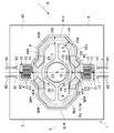
도 1에 나타내어지는 바와 같이, 액추에이터 장치(1)는, 지지부(2)와, 제1 가동부(3)와, 제2 가동부(4)와, 한 쌍의 제1 토션 바(5, 6)와, 한 쌍의 제2 토션 바(7, 8)와, 자계 발생부(9)를 구비하고 있다. 지지부(2), 제1 가동부(3), 제2 가동부(4), 한 쌍의 제1 토션 바(제1 연결부)(5, 6) 및 한 쌍의 제2 토션 바(제2 연결부)(7, 8)는, 예를 들면 SOI(Silicon on Insulator) 기판에 의해서 일체적으로 형성되어 있다. 즉, 액추에이터 장치(1)는, MEMS 디바이스로서 구성되어 있다. 액추에이터 장치(1)에서는, 서로 직교하는 X축(제1 축선) 및 Y축(제1 축선에 직교하는 제2 축선)의 각각의 둘레로, 미러면(10)이 마련된 제1 가동부(3)가 요동시켜진다. 액추에이터 장치(1)는, 예를 들면 광 통신용 광 스위치, 광 스캐너 등에 이용된다. 액추에이터 장치(1)는, MEMS 기술(패터닝, 에칭 등)을 이용하여 제조된다. As shown in Fig. 1, the
자계 발생부(9)는, 예를 들면 할바흐(Halbach) 배열이 취해진 영구자석 등에 의해서 구성되어 있다. 자계 발생부(9)는, 예를 들면, 평면에서 볼 때(X축 및 Y축에 직교하는 방향으로부터 본 경우에) X축 및 Y축 각각에 대해 45도 경사진 방향(D)의 자계를 발생시키고, 후술하는 코일(14)에 작용시킨다. 또, 자계 발생부(9)가 발생시키는 자계의 방향(D)은, 평면에서 볼 때 X축 및 Y축에 대해 45도 이외의 각도로 경사져 있어도 괜찮다. The
지지부(2)는, 예를 들면, 평면에서 볼 때 사각 형상의 외형을 가지며, 틀 모양으로 형성되어 있다. 지지부(2)는, 자계 발생부(9)에 대해서 X축 및 Y축에 직교하는 방향에서의 일방측에 배치되어 있다. 제1 가동부(3)는, 자계 발생부(9)로부터 이간한 상태에서, 지지부(2)의 내측에 배치되어 있다. 제1 가동부(3)는, 본체부(3a)와, 고리 모양부(3b)와, 한 쌍의 연결부(3c)를 가지고 있다. The
본체부(3a)는, 평면에서 볼 때 원 형상을 나타내고 있지만, 타원 형상, 사각 형상, 능(菱) 형상 등의 임의의 형상으로 형성되어도 괜찮다. 평면에서 볼 때의 본체부(3a)의 중심(P)은, X축과 Y축과의 교점과 일치하고 있다. 본체부(3a)에서의 자계 발생부와는 반대측의 표면에는, 예를 들면 알루미늄으로 이루어지는 금속막에 의해서 미러면(10)이 마련되어 있다. 미러면(10)은, 해당 표면에서의 전면(全面)에 마련되어 있지만, 해당 표면의 일부에만 마련되어도 괜찮다. 고리 모양부(3b)는, 평면에서 볼 때 본체부(3a)를 둘러싸도록 고리 모양으로 형성되어 있다. 고리 모양부(3b)는, 평면에서 볼 때 팔각 형상의 외형을 가지고 있지만, 원 형상, 타원 형상, 사각 형상, 능 형상 등의 임의의 외형을 가지고 있어도 괜찮다. 한 쌍의 연결부(3c)는, Y축 상에서의 본체부(3a)의 양측에 배치되고, 본체부(3a)와 고리 모양부(3b)를 서로 연결하고 있다. The
제2 가동부(4)는, 틀 모양으로 형성되어 있고, 자계 발생부(9)로부터 이간한 상태에서, 제1 가동부(3)를 둘러싸도록 지지부(2)의 내측에 배치되어 있다. 제2 가동부(4)는, 한 쌍의 제1 접속부(41A, 41B)와, 한 쌍의 제2 접속부(42A, 42B)와, 한 쌍의 제1 직선 모양부(43A, 43B)와, 한 쌍의 제2 직선 모양부(44A, 44B)와, 한 쌍의 제3 직선 모양부(45A, 45B)와, 한 쌍의 제4 직선 모양부(46A, 46B)를 가지고 있다. 제2 가동부(4)는, 평면에서 볼 때 X축 및 Y축 각각에 관해 대칭인 형상을 가지고 있다. 이하의 설명에서, X축 또는 Y축에 관해 대칭이란, 평면에서 볼 때의 대칭을 말한다. The second
제1 접속부(41A, 41B)는, X축에 평행한 X축 방향(제1 축 방향)에서의 제1 가동부(3)의 양측에 위치하고 있다. 즉, 각 제1 접속부(41A, 41B)는, 평면에서 볼 때 제1 가동부(3)와 X축 방향에 대향하는 부분을 가지고 있다. 각 제1 접속부(41A, 41B)는, Y축 방향을 따라서 연장되어 있다. The first connecting
제2 접속부(42A, 42B)는, Y축에 평행한 Y축 방향(제2축 방향)에서의 제1 가동부(3)의 양측에 위치하고 있다. 즉, 각 제2 접속부(42A, 42B)는, 평면에서 볼 때 제1 가동부(3)와 Y축 방향에 대향하는 부분을 가지고 있다. 각 제2 접속부(42A, 42B)는, X축 방향을 따라서 연장되어 있다. 평면에서 볼 때의 각 제2 접속부(42A, 42B)의 내부 가장자리(51)는, Y축 방향으로 패인 오목부(52)를 가지고 있고, 평면에서 볼 때의 각 제2 접속부(42A, 42B)의 외부 가장자리(53)는, Y축 방향으로 돌출되는 볼록부(54)를 가지고 있다. 오목부(52) 및 볼록부(54)는, 평면에서 볼 때 Y축 상에 위치하고 있다. The second connecting
평면에서 볼 때, 각 제2 접속부(42A, 42B)의 폭은, 제2 가동부(4)에서의 제1 접속부(41A, 41B) 및 제2 접속부(42A, 42B) 이외의 부분의 폭(최대폭)(W1)보다도 넓다. 즉, 각 제2 접속부(42A, 42B)의 폭은, Y축 상에서 최소폭(W2)이 되지만, 최소폭(W2)은, 폭(W1)보다도 넓다. 또, 각 제2 접속부(42A, 42B)의 최소폭(W2)은, 각 제1 접속부(41A, 41B)의 폭(최대폭)(W3)보다도 넓다. 각 제1 접속부(41A, 41B)의 폭(W3)은 폭(W1)보다도 넓지만, 폭(W1)과 동일해도 되고, 폭(W1)보다도 좁아도 괜찮다. 도 1에서는, 제1 접속부(41A)와 제1 토션 바(5)와의 사이의 경계가 일점 쇄선(B)로 나타내어져 있다. 또, 제2 가동부(4)에서의 어느 부분의 폭은, 평면에서 볼 때의 해당 부분의 내부 가장자리와 외부 가장자리와의 사이의 거리이며, 환언하면, X축 및 Y축에 직교하는 방향, 및 해당 부분의 연장 방향에 직교하는 방향(폭방향)에서의 해당 부분의 폭이다. When viewed in plan view, the width of each second connecting
제1 직선 모양부(43A, 43B)는, X축 방향에서의 제2 접속부(42A)의 양측에 위치하고, 제2 접속부(42A)에 접속되어 있다. 각 제1 직선 모양부(43A, 43B)는, X축 방향을 따라서 연장되어 있다. 제1 직선 모양부(43A, 43B)는, Y축에 관해 서로 대칭으로 배치되어 있다. 제2 직선 모양부(44A, 44B)는, X축 방향에서의 제2 접속부(42B)의 양측에 위치하고, 제2 접속부(42B)에 접속되어 있다. 각 제2 직선 모양부(44A, 44B)는, X축 방향을 따라서 연장되어 있다. 제2 직선 모양부(44A, 44B)는, Y축에 관해 서로 대칭으로 배치되어 있다. The first
제3 직선 모양부(45A, 45B)는, 각 제1 직선 모양부(43A, 43B)에 대해서 제2 접속부(42A)와는 반대측에 위치하고, 제1 직선 모양부(43A, 43B)와 제1 접속부(41A, 41B)에 접속되어 있다. 제3 직선 모양부(45A)는, 평면에서 볼 때, X축 및 Y축 각각에 대해 45도 경사진 방향을 따라서 연장되어 있다. 제3 직선 모양부(45B)는, 제3 직선 모양부(45A)에 대해서 Y축에 관해 대칭으로 연장되어 있다. The third
제4 직선 모양부(46A, 46B)는, 각 제2 직선 모양부(44A, 44B)에 대해서 제2 접속부(42B)와는 반대측에 위치하고, 제2 직선 모양부(44A, 44B)와 제1 접속부(41A, 41B)에 접속되어 있다. 제4 직선 모양부(46A)는, 제3 직선 모양부(45A)에 대해서 X축에 관해 대칭으로 연장되어 있다. 제4 직선 모양부(46B)는, 제4 직선 모양부(46A)에 대해서 Y축에 관해 대칭으로 연장됨과 아울러, 제3 직선 모양부(45B)에 대해서 X축에 관해 대칭으로 연장되어 있다. The fourth
제1 토션 바(5, 6)는, X축 상에서의 제1 가동부(3)의 양측에 배치되어 있다. 제1 토션 바(5, 6)는, 제1 가동부(3)가 X축 둘레로(X축을 중심선으로 하여) 요동 가능하게 되도록, X축 상에서 제1 가동부(3)(고리 모양부(3b))와 제2 가동부(4)를 서로 연결하고 있다. 제1 토션 바(5, 6)는, 제1 접속부(41A, 41B)에서 제2 가동부(4)에 접속되어 있다. 각 제1 토션 바(5, 6)는, X축을 따라 직선 모양으로 연장되어 있다. 본 실시 형태에서는, 제1 토션 바(5, 6)에 작용하는 응력의 완화를 위해서, 각 제1 토션 바(5, 6)에서의 제1 가동부(3)측의 단부의 폭(Y축 방향에서의 폭)은 제1 가동부(3)에 가까워질수록 넓어지고 있고, 제2 가동부(4)측의 단부의 폭(Y축 방향에서의 폭)은 제2 가동부(4)에 가까워질수록 넓어지고 있다. The
제2 토션 바(7, 8)는, Y축 상에서의 제2 가동부(4)의 양측에 배치되어 있다. 제2 토션 바(7, 8)는, 제2 가동부(4)가 Y축 둘레로(Y축을 중심선으로 하여) 요동 가능하게 되도록, Y축 상에서 제2 가동부(4)와 지지부(2)를 서로 연결하고 있다. 제2 토션 바(7, 8)는, 제2 접속부(42A, 42B)에서 제2 가동부(4)에 접속되어 있다. 각 제2 토션 바(7, 8)는, 평면에서 볼 때 사행(蛇行)하여 연장되어 있다. 각 제2 토션 바(7, 8)는, 복수의 직선 모양부(11)와, 복수의 접힘부(12)를 가지고 있다. 직선 모양부(11)는, Y축 방향으로 연장되고, X축 방향으로 늘어서 배치되어 있다. 접힘부(12)는, 서로 이웃하는 직선 모양부(11)의 양단을 교호로 연결하고 있다. The
액추에이터 장치(1)는, 한 쌍의 코일(14, 15)과, 제1 배선(21)과, 제2 배선(22)과, 제3 배선(23)과, 제4 배선(24)과, 제1 외부 단자(25)와, 제2 외부 단자(26)와, 제3 외부 단자(27)와, 제4 외부 단자(28)와, 4쌍의 와이어(29)를 더 구비하고 있다. 각 코일(14, 15)은, 제1 가동부(3)를 둘러싸도록 제2 가동부(4)에 마련되고, 평면에서 볼 때(각 코일(14, 15)이 배치된 평면에 직교하는 방향으로부터 본 경우에) 소용돌이 모양을 나타내고 있다. 각 코일(14, 15)은, X축 및 Y축을 포함하는 평면을 따라서 배치되어 있다. 각 코일(14, 15)은, 제1 가동부(3)의 둘레에 복수회 권회(卷回)되어 있다. 한 쌍의 코일(14, 15)은, 평면에서 볼 때 제2 가동부(4)의 폭방향으로 서로 다르게 늘어서도록, 배치되어 있다. The
도 1에서는, 코일(14, 15)이 배치되어 있는 배치 영역(R)이 해칭으로 나타내어져 있다. 각 코일(14, 15)은, 제1 접속부(41A, 41B) 및 각 직선 모양부(43A~46B)에서, 제1 접속부(41A, 41B) 및 각 직선 모양부(43A~46B)의 연장 방향을 따라서 연장되어 있다. 제1 접속부(41A, 41B) 및 각 직선 모양부(43A~46B)에서, 배치 영역(R)의 외부 가장자리는, 제1 접속부(41A, 41B) 및 각 직선 모양부(43A~46B)의 외부 가장자리를 따라서 있고, 배치 영역(R)의 내부 가장자리는, 제1 접속부(41A, 41B) 및 각 직선 모양부(43A~46B)의 내부 가장자리를 따라서 있다. In Fig. 1, the arrangement region R in which the
각 제2 접속부(42A, 42B)에서의 배치 영역(R)은, 제1 부분(55)과, 한 쌍의 제2 부분(56)과, 한 쌍의 제3 부분(57)을 포함하고 있다(도 2 참조). 제1 부분(55)은, X축 방향을 따라서 연장되고, 평면에서 볼 때 Y축과 교차하고 있다. 한 쌍의 제2 부분(56)은, X축 방향에서의 제1 부분(55)의 양측에 위치하고, 제1 부분(55)에 접속되어 있다. 일방의 제2 부분(56)은, X축 및 Y축 각각에 대해 45도 경사진 방향을 따라서 연장되어 있다. 타방의 제2 부분(56)은, 일방의 제2 부분(56)에 대해서 Y축에 관해 대칭으로 연장되어 있다. 제1 부분(55)은, 제2 접속부(42A)의 내부 가장자리(51)보다도 외부 가장자리(53)에 가까운 위치에 배치되어 있다. 한 쌍의 제3 부분(57)은, 각 제2 부분(56)에 대해서 제1 부분(55)과는 반대측에 위치하고, 한 쌍의 제2 부분(56)과, 제1 직선 모양부(43A, 43B)에서의 배치 영역(R)에 접속되어 있다. 각 제3 부분(57)은, X축 방향을 따라서 연장되어 있다. 제1 가동부(3)에는 코일이 마련되어 있지 않다. 또, 일방의 제2 부분(56)이 연장되는 방향은, X축 및 Y축에 대해 45도 이외의 각도로 경사져 있어도 괜찮다. The arrangement region R in each of the
각 외부 단자(25~28)는, 예를 들면 지지부(2)에 마련된 전극 패드이며, 절연층(35)으로부터 외부로 노출되어 있다. 절연층(35)은, 지지부(2), 제1 가동부(3), 제2 가동부(4), 제1 토션 바(5, 6) 및 제2 토션 바(7, 8)의 표면(자계 발생부(9)와는 반대측의 표면)을 덮도록 일체적으로 형성되어 있다. 외부 단자(25~28)에는, 각각, 한 쌍의 와이어(29)가 전기적으로 접속되어 있다. 각 와이어(29)는, 액추에이터 장치(1)로부터 외부로 인출되어 있다. 외부 단자(25~28)는, 각각, 액추에이터 장치(1)의 외부에 배치된 구동원 등과 와이어(29)를 통해서 전기적으로 접속되어 있다. Each of the
제1 배선(21)은, 코일(14)의 내측 단부와 제1 외부 단자(25)에 전기적으로 접속되어 있다. 제1 배선(21)은, 코일(14)의 내측 단부로부터 제2 토션 바(7)를 통해서 제1 외부 단자(25)까지 연장되어 있다. 제2 배선(22)은, 코일(14)의 외측 단부와 제2 외부 단자(26)에 전기적으로 접속되어 있다. 제2 배선(22)은, 예를 들면 Y축 상에서 코일(14)의 외측 단부에 접속되어 있다. 제2 배선(22)은, 코일(14)의 외측 단부로부터 제2 토션 바(8)를 통해서 제2 외부 단자(26)까지 연장되어 있다. The
제3 배선(23)은, 코일(15)의 내측 단부와 제3 외부 단자(27)에 전기적으로 접속되어 있다. 제3 배선(23)은, 코일(15)의 내측 단부로부터 제2 토션 바(7)를 통해서 제3 외부 단자(27)까지 연장되어 있다. 제4 배선(24)은, 코일(15)의 외측 단부와 제4 외부 단자(28)에 전기적으로 접속되어 있다. 제4 배선(24)은, 예를 들면 Y축 상에서 코일(15)의 외측 단부에 접속되어 있다. 제4 배선(24)은, 코일(15)의 외측 단부로부터 제2 토션 바(8)를 통해서 제4 외부 단자(28)까지 연장되어 있다. The
이상과 같이 구성된 액추에이터 장치(1)에서는, 각 외부 단자(25, 26) 및 각 배선(21, 22)을 통해서 코일(14)에 리니어 동작용의 구동 신호가 입력되면, 자계 발생부(9)가 발생하는 자계와의 상호작용에 의해서 코일(14)에 로렌츠 힘이 작용한다. 해당 로렌츠 힘과 제2 토션 바(7, 8)의 탄성력과의 균형을 이용함으로써, Y축 둘레로 미러면(10)(제1 가동부(3))을 제2 가동부(4)와 함께 리니어 동작시킬 수 있다. In the
한편, 각 외부 단자(27, 28) 및 각 배선(23, 24)을 통해서 코일(15)에 공진 동작용의 구동 신호가 입력되면, 자계 발생부(9)가 발생하는 자계와의 상호작용에 의해서 코일(15)에 로렌츠 힘이 작용한다. 해당 로렌츠 힘에 더하여, 공진 주파수에서의 제1 가동부(3)의 공진을 이용함으로써, X축 둘레로 미러면(10)(제1 가동부(3))을 공진 동작시킬 수 있다. 구체적으로는, X축 둘레에서의 제1 가동부(3)의 공진 주파수와 동일한 주파수의 구동 신호가 코일(15)에 입력되면, 제2 가동부(4)가 X축 둘레로 해당 주파수로 약간 진동한다. 이 진동이 제1 토션 바(5, 6)를 통해서 제1 가동부(3)에 전해지는 것에 의해, 제1 가동부(3)를 X축 둘레로 해당 주파수로 요동시킬 수 있다. On the other hand, when a driving signal for resonant operation is input to the
이어서, 도 1~도 3을 참조하면서, 코일(14)과 제1 배선(21)과의 접속 형태, 및 코일(15)과 제3 배선(23)의 접속 형태에 대해서 상세하게 설명한다. 도 2에 나타내어지는 바와 같이, 코일(14)의 내측 단부(14a)는, 제2 접속부(42A)에서의 Y축 상까지 연장되어 있다. 제1 배선(21)은, 인출 배선(61)과, 스트래들(straddle) 배선(62)을 가지고 있다. 인출 배선(61)은, 제2 가동부(4), 제2 토션 바(7) 및 지지부(2)에 걸쳐서 마련되고, 제1 외부 단자(25)에 전기적으로 접속되어 있다. 제2 가동부(4)에서의 인출 배선(61)은, 평면에서 볼 때 코일(14, 15)보다도 외측에 배치되고, 제2 접속부(42A)에서의 제1 직선 모양부(43A)측의 단부까지 연장되어 있다. 인출 배선(61)에서의 제1 외부 단자(25)와는 반대측의 단부(61a)는, 제2 가동부(4)의 폭방향에서 코일(14)의 내측 단부(14a)와 서로 마주하고 있다. Next, a connection form between the
스트래들 배선(62)은, 제2 가동부(4)에 마련되고, 코일(14)의 내측 단부(14a)와 인출 배선(61)의 단부(61a)에 전기적으로 접속되어 있다. 스트래들 배선(62)은, 평탄한 층 모양으로 형성되고, 코일(14, 15)의 상측(X축 및 Y축에 직교하는 방향에서의 코일(14, 15)의 일방측)에 걸치도록 연장되어 있다. 즉, 스트래들 배선(62)은, 코일(14, 15)과 입체적으로 교차하고 있다. 스트래들 배선(62)은, 평면에서 볼 때 인출 배선(61)의 단부(61a) 및 코일(14)의 내측 단부(14a)과 겹쳐지도록, 제2 접속부(42A)에서의 제1 직선 모양부(43A)측의 단부에 배치되고, 코일(14, 15)의 연장 방향에서의 배치 영역(R)의 일부를 덮고 있다. 또, 스트래들 배선(62)은, 도 1 및 도 2에서는 실선으로 그려져 있지만, 실제로는 절연층(35)에 의해서 덮여져 있다. The
스트래들 배선(62)은, 제1 부분(62a)과, 제1 부분(62a)에 접속된 제2 부분(62b)을 가지고 있다. 제1 부분(62a)은, 배치 영역(R)의 일방의 제2 부분(56) 상에 위치하고, X축 및 Y축 각각에 대해 45도 경사진 방향을 따라서 연장되어 있다. 제2 부분(62b)은, 배치 영역(R)의 일방의 제3 부분(57) 상에 위치하고, X축 방향을 따라서 연장되어 있다. 또, 제1 부분(62a)이 연장되는 방향은, X축 및 Y축에 대해 45도 이외의 각도로 경사져 있어도 괜찮다. The
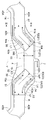
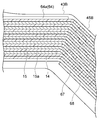
도 3은, 도 2에 나타내어지는 III-III선을 따른 단면도이다. 도 3에 나타내어지는 바와 같이, 제2 가동부(4)에는, 코일(14, 15)에 대응하는 형상을 가지는 홈부(31)가 마련되어 있다. 홈부(31)의 내면 상에는 절연층(32)이 마련되고, 절연층(32) 상에는 절연층(33)이 마련되어 있다. 각 코일(14, 15)은, 절연층(32, 33)을 사이에 두고 홈부(31) 내에 배치되어 있다. 즉, 각 코일(14, 15)은, 제2 가동부(4)에 매립되어 있다. 각 코일(14, 15)은, 예를 들면 다마신법(damascene法)에 의해서 홈부(31) 내에 동일한 금속재료가 매립되는 것에 의해 형성된 다마신 배선이다. 절연층(34)은, 코일(14, 15) 및 절연층(33)을 덮도록 마련되어 있다. 절연층(34) 상에는 절연층(35)이 마련되어 있다. 각 절연층(32~35)은, 예를 들면 산화 규소, 질화 규소, 산질화 규소 등에 의해서 구성되어 있다. 각 절연층(32~35)은, 지지부(2), 제1 가동부(3), 제2 가동부(4), 한 쌍의 제1 토션 바(5, 6) 및 한 쌍의 제2 토션 바(7, 8)의 표면(자계 발생부(9)와는 반대측의 표면)을 덮도록 일체적으로 형성되어 있다. 3 is a cross-sectional view taken along the line III-III shown in FIG. 2. As shown in FIG. 3, in the 2nd
인출 배선(61)은, 예를 들면, 코일(14, 15)과 동일하게 구성된 다마신 배선이다. 즉, 제2 가동부(4)에는, 홈부(36)가 마련되어 있고, 인출 배선(61)은, 절연층(32, 33)을 사이에 두고 홈부(36) 내에 배치되어 있다. 인출 배선(61)은, 제2 가동부(4)에 매립되어 있고, 절연층(34, 35)에 의해서 덮여져 있다. 인출 배선(61)은, 각 코일(14, 15)과 동일한 단면 형상을 가지고 있지만, 각 코일(14, 15)과는 다른 단면 형상을 가지고 있어도 괜찮다. 인출 배선(61)은, 코일(14, 15)을 구성하는 금속재료와 동일한 금속재료에 의해서 구성되어 있지만, 코일(14, 15)을 구성하는 금속재료와는 다른 금속재료에 의해서 구성되어도 괜찮다. The
스트래들 배선(62)은, 절연층(34) 상에 마련되고, 절연층(35)에 의해서 덮여져 있다. 절연층(34)에는, 평면에서 볼 때 코일(14)의 내측 단부(14a)에 대응하는 위치에 개구(34a)가 마련됨과 아울러, 평면에서 볼 때 인출 배선(61)의 단부(61a)에 대응하는 위치에 개구(34b)가 마련되어 있다. 스트래들 배선(62)은, 각 개구(34a, 34b)에 들어가 있고, 개구(34a, 34b)를 통해서 내측 단부(14a)와 단부(61a)에 접속되어 있다. 스트래들 배선(62)은, 인출 배선(61)을 구성하는 금속재료와는 다른 금속재료(예를 들면 알루미늄 또는 알루미늄계 합금)에 의해서 구성되어 있지만, 인출 배선(61)을 구성하는 금속재료와 동일한 금속재료에 의해서 구성되어도 괜찮다. The
스트래들 배선(62)의 폭(W4)은, 각 코일(14, 15)의 폭(W5)보다도 넓다. 또, 스트래들 배선(62)의 폭(W4)은, 코일(14, 15)의 배치 영역(R)의 폭(코일(14, 15) 전체의 폭)(W6)보다도 넓다. 스트래들 배선(62)의 폭(W4)은, 예를 들면, 각 코일(14, 15)의 폭(W5)의 5배 이상 100배 이하이다. 또, 스트래들 배선(62)의 폭(W4)은, 코일(14)의 내측 단부(14a)와의 접속단으로부터 인출 배선(61)의 단부(61a)와의 접속단을 향하는 방향에 직교하는 방향에서의 스트래들 배선(62)의 폭이며, 환언하면, 코일(14, 15)의 연장 방향에서의 스트래들 배선(62)의 폭이다. 본 실시 형태와 같이, 서로 다른 방향을 따라서 연장되는 제1 부분(62a) 및 제2 부분(62b)을 스트래들 배선(62)이 가지는 경우, 스트래들 배선(62)의 폭(W4)은, 제1 부분(62a)의 폭과 제2 부분(62b)의 폭과의 합이다. 이러한 점은, 후술하는 스트래들 배선(64)에 대해서도 마찬가지이다. 각 코일(14, 15)의 폭은, 코일(14, 15)의 연장 방향에 직교하는 방향에서의 각 코일(14, 15)을 구성하는 1개의 도체의 폭이다. 본 실시 형태에서는, 코일(14, 15)의 폭은 서로 동일하지만, 코일(14, 15)의 폭은 서로 달라도 괜찮다. The width W4 of the
스트래들 배선(62)의 두께(T1)는, 각 코일(14, 15)의 두께(T2)보다도 얇다. 스트래들 배선(62)의 단면적은, 각 코일(14, 15)의 단면적보다도 크다. 또, 스트래들 배선(62) 또는 코일(14, 15)의 두께는, 코일(14, 15)이 배치된 평면에 직교하는 방향에서의 스트래들 배선(62) 또는 코일(14, 15)의 두께이다. 본 실시 형태에서는, 코일(14, 15)의 두께는 서로 동일하지만, 코일(14, 15)의 두께는 서로 달라도 괜찮다. 스트래들 배선(62)의 단면적은, 코일(14)의 내측 단부(14a)와의 접속단으로부터 인출 배선(61)의 단부(61a)와의 접속단을 향하는 방향에 직교하는 단면에서의 스트래들 배선(62)의 단면적이며, 환언하면, 제2 가동부(4)의 폭방향에 직교하는 단면에서의 스트래들 배선(62)의 단면적이다. 본 실시 형태에서는, 스트래들 배선(62)의 단면적은, 제1 부분(62a)의 단면적과 제2 부분(62b)의 단면적과의 합이다. 이러한 점은, 후술하는 스트래들 배선(64)에 대해서도 마찬가지이다. 각 코일(14, 15)의 단면적은, 코일(14, 15)의 연장 방향에 직교하는 단면에서의 각 코일(14, 15)의 단면적이다. The thickness T1 of the
스트래들 배선(62)과 코일(14)과의 접촉 영역의 길이(L1)는, 코일(14, 15)의 폭(W5)보다도 크다. 즉, 절연층(34)에는, 도 2에 부호 L1으로 나타내어지는 범위에 걸쳐서 개구(34a)가 마련되어 있고, 스트래들 배선(62)과 코일(14)은, 해당 범위에서 서로 접촉하고 있다. 스트래들 배선(62)과 코일(14)과의 접촉 영역은, 코일(14, 15)의 연장 방향을 따라서 연장되어 있다. 스트래들 배선(62)과 인출 배선(61)과의 접촉 영역의 길이(L2)는, 코일(14, 15)의 폭(W5)보다도 크다. 즉, 절연층(34)에는, 도 2에 부호 L2로 나타내어지는 범위에 걸쳐서 개구(34b)가 마련되어 있고, 스트래들 배선(62)과 인출 배선(61)은, 해당 범위에서 서로 접촉하고 있다. 스트래들 배선(62)과 인출 배선(61)과의 접촉 영역은, 코일(14, 15)의 연장 방향을 따라서 연장되어 있다. The length L1 of the contact region between the
제3 배선(23)과 코일(15)과의 접속 형태는, 제1 배선(21)과 코일(14)과의 접속 형태와 동일하다. 도 2에 나타내어지는 바와 같이, 코일(15)의 내측 단부(15a)는, 제1 직선 모양부(43B)와 제3 직선 모양부(45B)와의 경계의 근방까지 연장되어 있다. 제3 배선(23)은, 인출 배선(63)과, 스트래들 배선(64)을 가지고 있다. 인출 배선(63)은, 제2 가동부(4), 제2 토션 바(7) 및 지지부(2)에 걸쳐서 마련되고, 제3 외부 단자(27)에 전기적으로 접속되어 있다. 제2 가동부(4)에서의 인출 배선(63)은, 평면에서 볼 때 코일(14, 15)보다도 외측에 배치되어 있고, 제2 접속부(42A)에서의 제1 직선 모양부(43B)측의 단부까지 연장되어 있다. 인출 배선(63)에서의 제3 외부 단자(27)와는 반대측의 단부(63a)는, 제2 가동부(4)의 폭방향에서 코일(15)의 내측 단부(15a)와 서로 마주하고 있다. 인출 배선(63)은, 인출 배선(61)과 마찬가지로 다마신 배선으로서 구성되어 있다. The connection pattern between the
스트래들 배선(64)은, 제2 가동부(4)에 마련되고, 코일(15)의 내측 단부(15a)와 인출 배선(63)의 단부(63a)에 전기적으로 접속되어 있다. 스트래들 배선(64)은, 평탄한 층 모양으로 형성되고, 코일(14, 15)의 상측에 걸치도록 연장되어 있다. 스트래들 배선(64)은, 평면에서 볼 때 인출 배선(63)의 단부(63a) 및 코일(15)의 내측 단부(15a)와 겹쳐지도록, 제2 접속부(42A)에서의 제1 직선 모양부(43B)측의 단부에 배치되고, 코일(14, 15)의 연장 방향에서의 배치 영역(R)의 일부를 덮고 있다. 스트래들 배선(64)은, 스트래들 배선(62)에 대해서 Y축에 관해 대칭으로 배치되어 있다. 스트래들 배선(64)은, 스트래들 배선(62)과 마찬가지로, 절연층(35)에 마련된 개구를 통해서 내측 단부(15a)와 단부(63a)에 접속되어 있다. 또, 스트래들 배선(64)은, 도 1 및 도 2에서는 실선으로 그려져 있지만, 실제로는 절연층(35)에 의해서 덮여져 있다. The
스트래들 배선(64)의 폭(W7)은, 각 코일(14, 15)의 폭(W5)보다도 넓다. 또, 스트래들 배선(64)의 폭(W7)은, 코일(14, 15)의 배치 영역(R)의 폭(W6)보다도 넓다. 스트래들 배선(64)의 두께는, 스트래들 배선(62)의 두께(T1)와 동일하고, 각 코일(14, 15)의 두께(T2)보다도 얇다. 스트래들 배선(64)의 단면적은, 각 코일(14, 15)의 단면적보다도 크다. The width W7 of the
스트래들 배선(64)과 코일(15)과의 접촉 영역의 길이(L3)는, 코일(14, 15)의 폭(W5)보다도 크다. 스트래들 배선(64)과 인출 배선(61)의 접촉 영역의 길이(L4)는, 코일(14, 15)의 폭(W5)보다도 크다. 또, 제2 배선(22) 및 제4 배선(24)은, 예를 들면, 인출 배선(61, 63)과 마찬가지로 다마신 배선으로서 구성되어 있다. The length L3 of the contact region between the
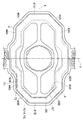
도 1에 나타내어지는 바와 같이, 제2 가동부(4)에는, 한 쌍의 더미 스트래들 배선(65, 66)이 마련되어 있다. 더미 스트래들 배선(65)은, 평면에서 볼 때, 스트래들 배선(64)에 대해서 제2 가동부(4)의 중심에 관해 점대칭으로 배치되어 있다. 더미 스트래들 배선(65)은, 스트래들 배선(64)과의 질량 밸런스 및 강성 밸런스를 조정하기 위해서 마련되어 있다. 더미 스트래들 배선(66)은, 평면에서 볼 때, 스트래들 배선(62)에 대해서 제2 가동부(4)의 중심에 관해 점대칭으로 배치되어 있다. 더미 스트래들 배선(66)은, 스트래들 배선(62)과의 질량 밸런스 및 강성 밸런스를 조정하기 위해서 마련되어 있다. 본 실시 형태에서는, 평면에서 볼 때의 제2 가동부(4)의 중심은, 본체부(3a)의 중심(P)(X축과 Y축과의 교점)와 일치하고 있다. As shown in FIG. 1, a pair of dummy straddle wirings 65 and 66 are provided in the 2nd
더미 스트래들 배선(65, 66)은, 스트래들 배선(62, 64)에 대응한 구성을 가지고 있다. 즉, 각 더미 스트래들 배선(65, 66)은, 평탄한 층 모양으로 형성되고, 코일(14, 15)의 상측에 걸치도록, 절연층(34)과 절연층(35)과의 사이에 배치되어 있다. 다만, 각 더미 스트래들 배선(65, 66)은, 코일(14, 15)에 전기적으로 접속되어 있지 않다. 즉, 더미 스트래들 배선(65, 66)의 형성 개소에서의 절연층(34)에는 개구(34a, 34b)가 마련되어 있지 않다. The dummy straddle wirings 65 and 66 have a configuration corresponding to the straddle wirings 62 and 64. That is, each
도 4~도 6에 나타내어지는 바와 같이, 제2 가동부(4)에는, 한 쌍의 더미 코일(67, 68) 및 한 쌍의 더미 코일(71, 72)이 마련되어 있다. 또, 도 4 및 도 6에서는, 코일(14, 15)에 해칭이 되어 있지만, 도 4 및 도 6은 단면을 나타내는 것은 아니다. As shown in Figs. 4 to 6, in the second
더미 코일(67)은, 코일(14)이 내측 단부(14a)로부터 소용돌이 모양으로 가상적으로 연장된 위치에 배치되어 있다. 더미 코일(67)은, 코일(14)과의 질량 밸런스 및 강성 밸런스를 조정하기 위해서 마련되어 있다. 더미 코일(67)은, 코일(14)에 대응한 구성을 가지고 있고, 제2 가동부(4)에 매립되어 있다. 더미 코일(67)은, 코일(14)에 전기적으로 접속되어 있지 않지만, 전기적으로 접속되어 있어도 괜찮다. 도 5에 나타내어지는 바와 같이, 더미 코일(67)은, 제2 접속부(42A)에서의 Y축 상으로부터, 제1 직선 모양부(43B), 제3 직선 모양부(45B), 제1 접속부(41B), 제4 직선 모양부(46B), 제2 직선 모양부(44B), 제2 접속부(42B) 및 제2 직선 모양부(44A)를 통해서, 제2 직선 모양부(44A)와 제4 직선 모양부(46A)와의 경계의 근방까지 연장되어 있다. The
더미 코일(68)은, 코일(15)이 내측 단부(15a)로부터 소용돌이 모양으로 가상적으로 연장된 위치에 배치되어 있다. 더미 코일(68)은, 코일(15)과의 질량 밸런스 및 강성 밸런스를 조정하기 위해서 마련되어 있다. 더미 코일(68)은, 코일(15)에 대응한 구성을 가지고 있고, 제2 가동부(4)에 매립되어 있다. 더미 코일(68)은, 코일(15)에 전기적으로 접속되어 있지 않지만, 전기적으로 접속되어 있어도 괜찮다. 도 5에 나타내어지는 바와 같이, 더미 코일(68)은, 제3 직선 모양부(45B)에서의 제1 직선 모양부(43B)측의 단부의 근방으로부터, 제1 접속부(41B) 및 제4 직선 모양부(46B)를 통해서, 제4 직선 모양부(46B)와 제2 직선 모양부(44B)와의 경계의 근방까지 연장되어 있다. The
도 5에 나타내어지는 바와 같이, 더미 코일(71)은, 평면에서 볼 때, 코일(14)의 외측 단부에 대해서 Y축에 관해 대칭으로 배치되어 있다. 더미 코일(71)은, 코일(14)과의 질량 밸런스 및 강성 밸런스를 조정하기 위해서 마련되어 있다. 더미 코일(71)은, 코일(14)에 대응한 구성을 가지고 있고, 제2 가동부(4)에 매립되어 있다. 더미 코일(71)은, 코일(14)에 전기적으로 접속되어 있지 않지만, 전기적으로 접속되어 있어도 괜찮다. 더미 코일(72)은, 평면에서 볼 때, 코일(15)의 외측 단부에 대해서 Y축에 관해 대칭으로 배치되어 있다. 더미 코일(72)은, 코일(15)과의 질량 밸런스 및 강성 밸런스를 조정하기 위해서 마련되어 있다. 더미 코일(72)은, 코일(15)에 대응한 구성을 가지고 있고, 제2 가동부(4)에 매립되어 있다. 더미 코일(72)은, 코일(15)에 전기적으로 접속되어 있지 않지만, 전기적으로 접속되어 있어도 괜찮다. As shown in FIG. 5, the
도 6에 나타내어지는 바와 같이, 코일(14)은, 코일(15)의 내측 단부(15a)보다도 내측의 위치에 있고, 제1 가동부(3)의 둘레에 복수회 권회되어 있다. 이것은, 코일(14)에 입력되는 전류량과 코일(15)에 입력되는 전류량이 다르고, 코일(14)의 감김수가 코일(15)의 감김수보다도 많기 때문이다. 코일(15)의 내측 단부(15a)보다도 내측의 위치에 있고, 코일(14)은, 코일(14)이 본래 배치되어야 할 위치 뿐만이 아니라, 코일(15)이 내측 단부(15a)로부터 소용돌이 모양으로 가상적으로 연장된 위치에도 배치되어 있다. 환언하면, 코일(14)은, 코일(15)이 연장되어 있지 않은 것에 의해서 빈 스페이스에도 배치되어 있다. 각 더미 코일(67, 68)은, 평면에서 볼 때 코일(14, 15)보다도 내측에 배치되어 있다. As shown in FIG. 6, the
도 7에 나타내어지는 바와 같이, 지지부(2)에서의 제1 배선(21)(인출 배선(61))은, 서로 병렬로 접속된 복수(이 예에서는 3개)의 배선부(21a)를 가지고 있다. 배선부(21a)는, 예를 들면 직선 모양으로 형성되고, 서로 폭방향으로 서로 이웃하도록 늘어서 배치되어 있다. 각 배선부(21a)는, 다마신 배선으로서 구성되어 있지만, 지지부(2)의 표면 상에 배치된 배선이라도 좋다. 도시는 생략되어 있지만, 지지부(2)에서의 각 배선(22~24)은, 제1 배선(21)과 마찬가지로, 서로 병렬로 접속된 복수(예를 들면, 3개)의 배선부를 가지고 있다. As shown in Fig. 7, the first wiring 21 (outgoing wiring 61) in the
이상 설명한 바와 같이, 액추에이터 장치(1)에서는, 코일(14)의 내측 단부(14a)와 인출 배선(61)이, 코일(14, 15)에 걸치도록 제2 가동부(4)에 마련된 스트래들 배선(62)에 의해서 서로 접속되어 있다. 스트래들 배선(62)의 폭(W4)은, 각 코일(14, 15)의 폭(W5)보다도 넓고, 스트래들 배선(62)의 두께(T1)는, 각 코일(14, 15)의 두께(T2)보다도 얇다. 마찬가지로, 코일(15)의 내측 단부(15a)와 인출 배선(63)이, 코일(14, 15)에 걸치도록 제2 가동부(4)에 마련된 스트래들 배선(64)에 의해서 서로 접속되어 있다. 스트래들 배선(64)의 폭(W7)은, 각 코일(14, 15)의 폭(W5)보다도 넓고, 스트래들 배선(64)의 두께는, 각 코일(14, 15)의 두께(T2)보다도 얇다. 이것에 의해, 스트래들 배선(62, 64)의 배선 저항을 저감할 수 있어, 코일(14, 15)에 입력되는 전류량이 증가한 경우에도 발열량의 증가를 억제할 수 있다. 게다가, 스트래들 배선(62, 64)의 폭(W4, W7)이 코일(14, 15)의 폭(W5)보다도 넓고, 스트래들 배선(62, 64)의 접지 면적이 넓기 때문에, 스트래들 배선(62, 64)이 벗겨지는 것을 억제할 수 있다. 그 결과, 스트래들 배선(62, 64)을 안정적으로 배치할 수 있어, 신뢰성을 향상시킬 수 있다. 게다가, 각 스트래들 배선(62, 64)의 두께(T1)가 각 코일(14, 15)의 두께(T2)보다도 얇기 때문에, 스트래들 배선(62, 64)에 의해서 제2 가동부(4)의 표면에 요철이 형성되어 버리는 것을 억제할 수 있어, 신뢰성의 향상 및 제조의 용이화를 도모할 수 있다. 따라서, 액추에이터 장치(1)에 의하면, 코일(14, 15)에 입력되는 전류량이 증가한 경우에도 발열량의 증가를 억제할 수 있음과 아울러, 제조를 용이화할 수 있다. 또, 스트래들 배선(62, 64)의 폭(W4, W7)이 넓고, 평면에서 볼 때의 스트래들 배선(62, 64)의 면적이 큰 경우, 기생(寄生) 용량이 증가하기 때문에, 구동시에 스파이크 노이즈가 발생할 가능성이 있지만, 액추에이터 장치(1)에서는, 스트래들 배선(62, 64)의 폭(W4, W7)을 억지로 증가시키는 것에 의해, 양호한 특성이 얻어지고 있다. As described above, in the
액추에이터 장치(1)에서는, 코일(14)과 스트래들 배선(62)과의 접촉 영역의 길이(L1)가, 각 코일(14, 15)의 폭(W5)보다도 크다. 마찬가지로, 코일(15)과 스트래들 배선(64)과의 접촉 영역의 길이(L3)가, 코일(14, 15)의 폭(W5)보다도 크다. 이것에 의해, 코일(14, 15)과 스트래들 배선(62, 64)과의 사이의 접촉 저항을 저감할 수 있어, 발열량의 증가를 효과적으로 억제할 수 있다. In the
액추에이터 장치(1)에서는, 인출 배선(61)과 스트래들 배선(62)과의 접촉 영역의 길이(L3)가, 코일(14, 15)의 폭(W5)보다도 크다. 마찬가지로, 인출 배선(63)과 스트래들 배선(64)과의 접촉 영역의 길이(L4)가, 코일(14, 15)의 폭(W5)보다도 크다. 이것에 의해, 인출 배선(61, 63)과 스트래들 배선(62, 64)과의 사이의 접촉 저항을 저감할 수 있어, 발열량의 증가를 보다 효과적으로 억제할 수 있다. In the
액추에이터 장치(1)에서는, 스트래들 배선(62, 64)의 단면적이, 코일(14, 15)의 단면적보다도 크다. 이것에 의해, 발열량의 증가를 보다 한층 효과적으로 억제할 수 있다. In the
액추에이터 장치(1)에서는, 스트래들 배선(62)의 폭(W4) 및 스트래들 배선(64)의 폭(W7)이, 코일(14, 15)의 배치 영역(R)의 폭(W6)보다도 넓다. 이것에 의해, 발열량의 증가를 보다 한층 효과적으로 억제할 수 있다. In the
액추에이터 장치(1)에서는, 코일(14, 15)이 제2 가동부(4)에 매립되어 있고, 각 스트래들 배선(62, 64)이, 평탄한 층 모양으로 형성되고, 코일(14, 15)의 상측에 걸치도록 연장되어 있다. 이것에 의해, 코일(14, 15)을 안정적으로 배치할 수 있어, 신뢰성을 한층 향상시킬 수 있다. 게다가, 스트래들 배선(62)에 의해서 제2 가동부(4)의 표면에 요철이 형성되어 버리는 것을 효과적으로 억제할 수 있어, 제조를 한층 용이화할 수 있다. 게다가, 코일(14, 15)이 제2 가동부(4)에 매립된 후에, 제2 가동부(4) 및 코일(14, 15)의 표면을 평탄화하는 공정을 행할 수 있기 때문에, 스트래들 배선(62, 64)을 평탄한 표면 상에 형성할 수 있어, 제조를 한층 용이화할 수 있다. 제2 가동부(4) 및 코일(14, 15)의 표면을 평탄화했다고 해도, 해당 표면에 약간의 요철이 잔존하는 경우가 있다. 액추에이터 장치(1)에서는, 스트래들 배선(62, 64)이 그러한 요철 상에 형성되었다고 해도, 스트래들 배선(62, 64)의 폭(W4, W7)이 코일(14, 15)의 폭(W5)보다도 넓고, 스트래들 배선(62, 64)의 접지 면적이 넓기 때문에, 스트래들 배선(62, 64)이 벗겨지는 것을 억제할 수 있어, 스트래들 배선(62, 64)을 안정적으로 배치할 수 있다. In the
액추에이터 장치(1)에서는, 제1 배선(21)이, 코일(14)의 내측 단부(14a)로부터 제2 토션 바(7)를 통해서 제1 외부 단자(25)까지 연장되어 있고, 제2 배선(22)이, 코일(14)의 외측 단부로부터 제2 토션 바(8)를 통해서 제2 외부 단자(26)까지 연장되어 있다. 이것에 의해, 제1 배선(21)이 제2 토션 바(7)를 통과함과 아울러 제2 배선(22)이 제2 토션 바(8)를 통과하기 때문에, 예를 들면 제1 배선(21) 및 제2 배선(22) 쌍방이 제2 토션 바(7)를 통과하는 경우와 비교하여, 제2 토션 바(7, 8) 사이에서 발열량을 균일화시킬 수 있다. 그 결과, 열 분포의 편차에 기인하여 제2 가동부(4)의 고유 진동수나 강성이 변화해 버리는 것을 억제할 수 있다. In the
액추에이터 장치(1)에서는, 제2 가동부(4)에는, 코일(14)이 내측 단부(14a)로부터 소용돌이 모양으로 가상적으로 연장된 위치에, 코일(14)과의 질량 밸런스를 조정하기 위한 더미 코일(67)이 마련됨과 아울러, 코일(15)이 내측 단부(15a)로부터 소용돌이 모양으로 가상적으로 연장된 위치에, 코일(15)과의 질량 밸런스를 조정하기 위한 더미 코일(68)이 마련되어 있다. 이것에 의해, 제2 가동부(4)의 질량 밸런스 및 강성 밸런스를 향상시킬 수 있다. In the
액추에이터 장치(1)에서는, 제2 가동부(4)에는, 스트래들 배선(62)과의 질량 밸런스를 조정하기 위한 더미 스트래들 배선(65)과, 스트래들 배선(64)과의 질량 밸런스를 조정하기 위한 더미 스트래들 배선(66)이 마련되어 있다. 이것에 의해, 제2 가동부(4)의 질량 밸런스 및 강성 밸런스를 향상시킬 수 있다. In the
액추에이터 장치(1)에서는, 더미 스트래들 배선(65)이, 평면에서 볼 때, 스트래들 배선(62)에 대해서 제2 가동부(4)의 중심에 관해 점대칭이 되는 위치에 배치되어 있다. 마찬가지로, 더미 스트래들 배선(66)이, 평면에서 볼 때, 스트래들 배선(64)에 대해서 제2 가동부(4)의 중심에 관해 점대칭이 되는 위치에 배치되어 있다. 이것에 의해, 제2 가동부(4)의 질량 밸런스 및 강성 밸런스를 효과적으로 향상시킬 수 있다. In the
액추에이터 장치(1)에서는, 한 쌍의 코일(14, 15)이, 평면에서 볼 때 제2 가동부(4)의 폭방향으로 서로 다르게 늘어서도록, 배치되어 있다. 이것에 의해, 제1 가동부(3)를 바람직하게 구동시킬 수 있다. In the
액추에이터 장치(1)에서는, 코일(14)은, 코일(15)이 내측 단부(15a)로부터 소용돌이 모양으로 가상적으로 연장된 위치에 배치되어 있다. 이것에 의해, 코일(14)를 보다 외측에 배치할 수 있어, 구동력을 증가시킬 수 있다. In the
액추에이터 장치(1)에서는, 제2 토션 바(7, 8)가, Y축 둘레로 제2 가동부(4)가 요동 가능하게 되도록, 제2 가동부(4)와 지지부(2)를 서로 연결하고 있다. 이것에 의해, 제2 가동부(4)를 제1 가동부(3)와 함께 Y축 둘레로 요동시킬 수 있다. In the
액추에이터 장치(1)에서는, 지지부(2)에서의 제1 배선(21)이, 서로 병렬로 접속된 복수의 배선부(21a)를 가지고 있다. 이것에 의해, 지지부(2)에서의 제1 배선(21)의 배선 저항을 저감할 수 있어, 발열량의 증가를 보다 한층 효과적으로 억제할 수 있다. In the
액추에이터 장치(1)는, 각 외부 단자(25~28)에 각각 접속되고 외부로 인출된 4쌍의 와이어(29)를 구비하고 있다. 이것에 의해, 각 외부 단자(25~28)로부터 인출되는 배선의 배선 저항을 저감할 수 있어, 발열량의 증가를 보다 한층 효과적으로 억제할 수 있다. The
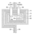
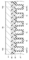
이상, 본 개시의 일 실시 형태에 대해 설명했지만, 본 개시는, 상기 실시 형태에 한정되지 않는다. 예를 들면, 도 8에 나타내어지는 변형예와 같이, 코일(14, 15) 및 인출 배선(61)은, 제2 가동부(4) 상에 배치되어도 괜찮다. 이 변형예에서는, 제2 가동부(4)의 표면 상에 절연층(34)이 마련되고, 절연층(34) 상에 스트래들 배선(62)이 마련되어 있다. 절연층(34) 상에는, 스트래들 배선(62)을 덮도록 절연층(35)이 마련되어 있다. 코일(14, 15) 및 인출 배선(61)은, 절연층(35) 상에 마련되어 있다. 즉, 코일(14, 15)은, 절연층(34, 35)을 통해서 제2 가동부(4) 상에 배치되어 있고, 스트래들 배선(62)은, 코일(14, 15)의 하측에 걸치도록, 코일(14, 15)과 제2 가동부(4)와의 사이로 연장되어 있다. As described above, one embodiment of the present disclosure has been described, but the present disclosure is not limited to the above embodiment. For example, as in the modified example shown in FIG. 8, the
절연층(35)에는, 평면에서 볼 때 코일(14)의 내측 단부(14a)에 대응하는 위치에 개구(35a)가 마련됨과 아울러, 평면에서 볼 때 인출 배선(61)의 단부(61a)에 대응하는 위치에 개구(35b)가 마련되어 있다. 스트래들 배선(62)은, 각 개구(35a, 35b)에 들어가 있고, 개구(35a, 35b)를 통해서 내측 단부(14a)와 단부(61a)에 접속되어 있다. 절연층(35) 상에는, 각 코일(14, 15) 및 인출 배선(61)을 덮도록 절연층(37)이 마련되어 있다. 절연층(37)은, 각 코일(14, 15) 및 인출 배선(61)의 보호를 위해서 마련되어 있다. 각 코일(14, 15) 및 인출 배선(61)이 예를 들면 금 등의 부식 내성을 가지는 금속재료에 의해서 구성되어 있는 경우에는, 절연층(35)은 마련되어 있지 않아도 괜찮다. 스트래들 배선(64)에 대해서도 스트래들 배선(62)과 마찬가지로, 코일(14, 15)의 하측에 걸치도록, 코일(14, 15)과 제2 가동부(4)와의 사이에 배치된다. In the insulating
이러한 변형예에 의해서도, 상기 실시 형태와 마찬가지로, 코일(14, 15)에 입력되는 전류량이 증가한 경우에도 발열량의 증가를 억제할 수 있음과 아울러, 신뢰성의 향상 및 제조의 용이화를 도모할 수 있다. 게다가, 코일(14, 15)이 제2 가동부(4) 상에 배치되어 있고, 스트래들 배선(62, 64)이, 코일(14, 15)의 하측에 걸치도록, 코일(14, 15)과 제2 가동부(4)와의 사이에 연장되어 있기 때문에, 스트래들 배선(62, 64)의 보호를 도모할 수 있다. 게다가, 스트래들 배선(62, 64)의 두께(T1)가 각 코일(14, 15)의 두께(T2)보다도 얇기 때문에, 스트래들 배선(62, 64)의 상측에 걸치도록 코일(14, 15)을 용이하게 형성할 수 있다. 그 결과, 코일(14, 15)에 파손 등(예를 들면 균열)이 생기는 것을 억제할 수 있어, 코일(14, 15)의 신뢰성을 향상시킬 수 있다. According to this modification, as in the above embodiment, even when the amount of current input to the
상기 실시 형태에서는, Y축 둘레로 제1 가동부(3) 및 제2 가동부(4)를 리니어 동작시켰지만, Y축 둘레로 제1 가동부(3) 및 제2 가동부(4)를 공진 동작시켜도 괜찮다. 상기 실시 형태에서는, 제2 가동부(4)에 한 쌍의 코일(14, 15)이 마련되어 있었지만, 제2 가동부(4)에 1개의 코일만이 마련되어도 괜찮다. 이 경우에도, 해당 코일로의 구동 신호의 입력에 의해, 제1 가동부(3)를 X축 둘레로 요동시킴과 아울러 제2 가동부(4)를 Y축 둘레로 요동시킬 수 있다. 제2 가동부(4)에 코일(14)만이 마련되는 경우, 각 배선(23, 24) 및 각 외부 단자(27, 28)은 생략되지만, 상기 실시 형태에서 스트래들 배선(64)이 배치되어 있던 위치에, 스트래들 배선(62)과의 질량 밸런스를 조정하기 위한 더미 스트래들 배선이 마련되어도 괜찮다. 즉, 제2 가동부(4)에는, 평면에서 볼 때 스트래들 배선(62)에 대해서 Y축에 관해 대칭인 위치에, 더미 스트래들 배선이 마련되어도 괜찮다. 상기 실시 형태에서, 기전력을 측정하기 위한 기전력 모니터 코일이 제2 가동부(4)에 마련되어도 괜찮고, 온도를 측정하기 위한 온도 센서 코일이 지지부(2)에 마련되어도 괜찮다. In the above embodiment, the first
상기 실시 형태에서는, X축 및 Y축 각각의 둘레로 제1 가동부(3)가 요동 시켜졌지만, X축 둘레로만 제1 가동부(3)가 요동시켜지도록 액추에이터 장치(1)가 구성되어도 괜찮다. 이 경우, 제2 연결부는, 제2 토션 바(7, 8)와 같이 비틀림 변형 가능한 것이 아니라도 괜찮고, 제2 가동부(4)를 진동시키는 것에 의해서 X축 둘레로 제1 가동부(3)가 요동 가능하게 되도록(제2 가동부(4)가 적어도 X축 둘레로 진동 가능하게 되도록), 제2 가동부(4)와 지지부(2)를 서로 연결하는 것이면 좋다. 이러한 제2 연결부의 설계 자유도는 비교적 높다. 예를 들면, 제2 연결부는, Y축 상에서의 제2 가동부(4)의 양측에 배치되고, Y축 상에서 제2 가동부(4)와 지지부(2)에 접속된 한 쌍의 부재라도 좋고, Y축 상 및/또는 Y축 상 이외의 위치에서, 제2 가동부(4)와 지지부(2)에 접속된 복수 쌍의 부재라도 괜찮다. 혹은, 제2 연결부는, X축 상에서의 제2 가동부(4)의 양측에 배치되고, X축 상에서 제2 가동부(4)와 지지부(2)에 접속된 한 쌍의 부재라도 괜찮다. 이들의 경우, 제2 가동부(4)에는, 1개의 코일이 마련된다. 해당 코일로의 구동 신호의 입력에 의해, 제1 가동부(3)를 X축 둘레로 요동시킬 수 있다. In the above embodiment, the first
제2 가동부(4)에 코일(14)만이 마련되는 경우, 제1 배선(21)이 제2 토션 바(7)를 통과함과 아울러 제2 배선(22)이 제2 토션 바(8)를 통과해도 괜찮지만, 제1 배선(21) 및 제2 배선(22) 쌍방이 제2 토션 바(7)를 통과해도 괜찮다. 이 경우, 더미 코일(67)을 생략할 수 있다. 스트래들 배선(62)의 폭(W4) 및 스트래들 배선(64)의 폭(W7) 중 적어도 일방은, 코일(14, 15)의 배치 영역(R)의 폭(W6)보다도 좁아도 좋다. 코일(14)과 스트래들 배선(62)과의 접촉 영역의 길이(L1), 인출 배선(61)과 스트래들 배선(62)과의 접촉 영역의 길이(L2), 코일(15)과 스트래들 배선(64)과의 접촉 영역의 길이(L3), 및 인출 배선(63)과 스트래들 배선(64)과의 접촉 영역의 길이(L4) 중 적어도 하나는, 코일(14, 15)의 폭(W5)보다도 작아도 괜찮다. When only the
각 구성의 재료 및 형상에는, 상술한 재료 및 형상에 한정하지 않고, 여러가지 재료 및 형상을 채용할 수 있다. 예를 들면, 스트래들 배선(62, 64)은, 일방향을 따라서 연장되는 부분만을 가지고 있어도 되며, 스트래들 배선(62, 64)의 형상 및 배치는 상술한 예에 한정되지 않는다. 제2 가동부(4)는, 평면에서 볼 때 대략 원 형상, 대략 타원 형상, 대략 사각 형상 또는 대략 능 형상 등을 나타내고 있어도 괜찮다. 고리 모양부(3b)가 마련되지 않고, 제1 토션 바(5, 6)가 본체부(3a)에 직접 접속되어도 괜찮다. 제2 토션 바(7, 8)는, 평면에서 볼 때 직선 모양으로 연장되어 있어도 괜찮다. 제2 토션 바(7, 8)는, 제2 가동부(4)가 Y축 둘레로 요동 가능하게 되도록, Y축 상 이외의 위치에서 제2 가동부(4)와 지지부(2)를 서로 연결하고 있어도 괜찮다. 더미 스트래들 배선(65, 66) 및 더미 코일(67, 68) 중 적어도 일방은 마련되어 있지 않아도 좋다. 액추에이터 장치(1)는, 미러면(10) 이외를 구동하는 것이라도 괜찮다. 상기 실시 형태에서는, 한 쌍의 코일(14, 15)이 서로 다르게 늘어서도록 배치되어 있었지만, 평면에서 볼 때 코일(14, 15)의 일방이 타방의 내측에 배치되어도 괜찮다. 3개 이상의 와이어(29)가 제1 외부 단자(25)에 접속되어도 괜찮다. 상기 변형예에서, 제2 가동부 상에 마련된 코일(14, 15)의 상측에 걸치도록, 스트래들 배선(62)이 마련되어도 괜찮다. 상기 실시 형태에서는, 제2 가동부(4)를 진동시키는 것에 의해서 제1 가동부(3)가 요동시켜졌지만, 제1 가동부(3)에 코일이 마련되고, 해당 코일에 작용하는 로렌츠 힘에 의해서 제1 가동부(3)가 직접 요동시켜져도 괜찮다. 이 경우에도, 상기 실시 형태와 마찬가지로, 발열량의 증가를 억제할 수 있다. The materials and shapes of each configuration are not limited to the materials and shapes described above, and various materials and shapes can be adopted. For example, the straddle wirings 62 and 64 may have only a portion extending along one direction, and the shape and arrangement of the straddle wirings 62 and 64 are not limited to the above-described example. The second
1 - 액추에이터 장치
2 - 지지부
3 - 제1 가동부
4 - 제2 가동부
5, 6 - 제1 토션 바(제1 연결부)
7, 8 - 제2 토션 바(제2 연결부)
9 - 자계 발생부
14, 15 - 코일
21 - 제1 배선
21a - 배선부
22 - 제2 배선
25 - 제1 외부 단자
26 - 제2 외부 단자
29 - 와이어
61, 63 - 인출 배선
62, 64 - 스트래들 배선
65, 66 - 더미 스트래들 배선
67, 68 - 더미 코일1-actuator device 2-support
3-1st movable part 4-2nd movable part
5, 6-first torsion bar (first connection) 7, 8-second torsion bar (second connection)
9-
21-
22-second wiring 25-first external terminal
26-second external terminal 29-wire
61, 63-
65, 66-
Claims (16)
제1 가동부와,
상기 제1 가동부를 둘러싸도록 배치된 틀 모양의 제2 가동부와,
제1 축선 둘레로 상기 제1 가동부가 요동 가능하게 되도록, 상기 제1 가동부와 상기 제2 가동부를 서로 연결하는 제1 연결부와,
상기 제2 가동부를 진동시키는 것에 의해서 상기 제1 축선 둘레로 상기 제1 가동부가 요동 가능하게 되도록, 상기 제2 가동부와 상기 지지부를 서로 연결하는 제2 연결부와,
상기 제2 가동부에 마련된 소용돌이 모양의 코일과,
상기 코일에 작용하는 자계(磁界)를 발생시키는 자계 발생부와,
상기 지지부에 마련된 제1 외부 단자와,
상기 코일의 내측 단부와 상기 제1 외부 단자에 접속된 제1 배선을 구비하며,
상기 제1 배선은, 상기 제1 외부 단자에 접속된 인출 배선과, 상기 코일에 걸치도록 상기 제2 가동부에 마련되고, 상기 코일의 상기 내측 단부와 상기 인출 배선에 접속된 스트래들(straddle) 배선을 가지며,
상기 스트래들 배선의 폭은, 상기 코일의 폭보다도 넓고,
상기 스트래들 배선의 두께는, 상기 코일의 두께보다도 얇은 액추에이터 장치.With the support,
A first movable part,
A frame-shaped second movable part disposed so as to surround the first movable part,
A first connection part connecting the first movable part and the second movable part to each other so that the first movable part can swing around a first axis,
A second connection part connecting the second movable part and the support part to each other so that the first movable part can be swung around the first axis by vibrating the second movable part,
A spiral coil provided on the second movable portion,
A magnetic field generator for generating a magnetic field acting on the coil,
A first external terminal provided on the support,
A first wiring connected to the inner end of the coil and the first external terminal,
The first wiring includes a lead wiring connected to the first external terminal, and a straddle provided on the second movable portion so as to span the coil, and connected to the inner end of the coil and the lead wiring Have wiring,
The width of the straddle wiring is wider than the width of the coil,
The thickness of the straddle wiring is thinner than that of the coil.
상기 코일과 상기 스트래들 배선과의 접촉 영역의 길이는, 상기 코일의 폭보다도 큰 액추에이터 장치.The method according to claim 1,
The actuator device having a length of a contact area between the coil and the straddle wiring is larger than a width of the coil.
상기 인출 배선과 상기 스트래들 배선과의 접촉 영역의 길이는, 상기 코일의 폭보다도 큰 액추에이터 장치.The method according to claim 1 or claim 2,
An actuator device in which a length of a contact area between the lead wiring and the straddle wiring is larger than a width of the coil.
상기 스트래들 배선의 단면적은, 상기 코일의 단면적보다도 큰 액추에이터 장치.The method according to any one of claims 1 to 3,
An actuator device in which the cross-sectional area of the straddle wiring is larger than the cross-sectional area of the coil.
상기 스트래들 배선의 폭은, 상기 코일의 배치 영역의 폭보다도 넓은 액추에이터 장치.The method according to any one of claims 1 to 4,
The actuator device having a width of the straddle wiring is wider than a width of an arrangement region of the coil.
상기 코일은, 상기 제2 가동부에 매립되어 있고,
상기 스트래들 배선은, 평탄한 층 모양으로 형성되고, 상기 코일의 상측에 걸치도록 연장되어 있는 액추에이터 장치.The method according to any one of claims 1 to 5,
The coil is embedded in the second movable part,
The straddle wiring is formed in a flat layer shape and extends so as to extend over the coil.
상기 코일은, 상기 제2 가동부 상에 배치되어 있고,
상기 스트래들 배선은, 상기 코일의 하측에 걸치도록, 상기 코일과 상기 제2 가동부와의 사이에 연장되어 있는 액추에이터 장치.The method according to any one of claims 1 to 5,
The coil is disposed on the second movable part,
The straddle wiring is an actuator device extending between the coil and the second movable part so as to span the lower side of the coil.
상기 지지부 상에 마련된 제2 외부 단자와, 상기 코일의 외측 단부와 상기 제2 외부 단자에 접속된 제2 배선을 더 구비하고,
상기 제2 연결부를 한 쌍 구비하고,
상기 제1 배선은, 상기 코일의 상기 내측 단부로부터 상기 한 쌍의 제2 연결부의 일방을 통해서 상기 제1 외부 단자까지 연장되어 있고,
상기 제2 배선은, 상기 코일의 상기 외측 단부로부터 상기 한 쌍의 제2 연결부의 타방을 통해서 상기 제2 외부 단자까지 연장되어 있는 액추에이터 장치.The method according to any one of claims 1 to 7,
A second external terminal provided on the support part, and a second wiring connected to the outer end of the coil and the second external terminal,
It has a pair of the second connection,
The first wiring extends from the inner end of the coil to the first external terminal through one of the pair of second connecting portions,
The second wiring is an actuator device extending from the outer end of the coil to the second external terminal through the other side of the pair of second connecting portions.
상기 제2 가동부에는, 상기 코일이 상기 내측 단부로부터 소용돌이 모양으로 가상적으로 연장된 위치에, 상기 코일과의 질량 밸런스를 조정하기 위한 더미(dummy) 코일이 마련되어 있는 액추에이터 장치.The method according to claim 7,
In the second movable part, a dummy coil for adjusting a mass balance with the coil is provided at a position in which the coil virtually extends in a spiral shape from the inner end.
상기 제2 가동부에는, 상기 스트래들 배선과의 질량 밸런스를 조정하기 위한 더미 스트래들 배선이 마련되어 있는 액추에이터 장치.The method according to any one of claims 1 to 9,
An actuator device provided with a dummy straddle wire for adjusting a mass balance with the straddle wire in the second movable part.
상기 더미 스트래들 배선은, 상기 코일이 배치된 평면에 직교하는 방향으로부터 본 경우에, 상기 스트래들 배선에 대해서 상기 제2 가동부의 중심에 관해 점대칭으로 배치되어 있는 액추에이터 장치.The method according to claim 10,
The dummy straddle wiring is arranged point-symmetrically with respect to the straddle wiring with respect to the center of the second movable portion when viewed from a direction orthogonal to a plane in which the coil is disposed.
상기 코일을 한 쌍 구비하며,
상기 한 쌍의 코일은, 상기 코일이 배치된 평면에 직교하는 방향으로부터 본 경우에, 상기 제2 가동부의 폭방향으로 서로 다르게 늘어서도록, 배치되어 있는 액추에이터 장치.The method according to any one of claims 1 to 11,
And a pair of the coils,
The actuator device of the pair of coils is arranged so as to line up differently in the width direction of the second movable part when viewed from a direction orthogonal to a plane in which the coils are arranged.
상기 한 쌍의 코일의 일방은, 상기 한 쌍의 코일의 타방이 상기 내측 단부로부터 소용돌이 모양으로 가상적으로 연장된 위치에, 배치되어 있는 액추에이터 장치.The method of claim 12,
One of the pair of coils is disposed at a position in which the other of the pair of coils virtually extends from the inner end in a spiral shape.
상기 제2 연결부는, 상기 제1 축선에 직교하는 제2 축선 둘레로 상기 제2 가동부가 요동 가능하게 되도록, 상기 제2 가동부와 상기 지지부를 서로 연결하고 있는 액추에이터 장치.The method according to any one of claims 1 to 13,
The second connecting portion is an actuator device that connects the second movable portion and the support portion to each other so that the second movable portion can be swung around a second axis orthogonal to the first axis.
상기 지지부에서의 상기 제1 배선은, 서로 병렬로 접속된 복수의 배선부를 가지는 액추에이터 장치.The method according to any one of claims 1 to 14,
The first wiring in the support portion has a plurality of wiring portions connected in parallel with each other.
상기 제1 외부 단자에 접속되고, 외부로 인출된 한 쌍의 와이어를 더 구비하는 액추에이터 장치.The method according to any one of claims 1 to 15,
The actuator device further comprising a pair of wires connected to the first external terminal and drawn out.
Applications Claiming Priority (3)
| Application Number | Priority Date | Filing Date | Title |
|---|---|---|---|
| JPJP-P-2017-232057 | 2017-12-01 | ||
| JP2017232057 | 2017-12-01 | ||
| PCT/JP2018/043412 WO2019107311A1 (en) | 2017-12-01 | 2018-11-26 | Actuator device |
Publications (1)
| Publication Number | Publication Date |
|---|---|
| KR20200095458A true KR20200095458A (en) | 2020-08-10 |
Family
ID=66665028
Family Applications (1)
| Application Number | Title | Priority Date | Filing Date |
|---|---|---|---|
| KR1020207009598A KR20200095458A (en) | 2017-12-01 | 2018-11-26 | Actuator device |
Country Status (6)
| Country | Link |
|---|---|
| US (4) | US11394284B2 (en) |
| EP (1) | EP3719558B1 (en) |
| JP (4) | JP6546370B1 (en) |
| KR (1) | KR20200095458A (en) |
| CN (2) | CN115051526A (en) |
| WO (1) | WO2019107311A1 (en) |
Families Citing this family (5)
| Publication number | Priority date | Publication date | Assignee | Title |
|---|---|---|---|---|
| JP6696777B2 (en) | 2016-01-21 | 2020-05-20 | 浜松ホトニクス株式会社 | Actuator device |
| CN115051526A (en) | 2017-12-01 | 2022-09-13 | 浜松光子学株式会社 | Actuator device |
| IT201900004199A1 (en) * | 2019-03-22 | 2020-09-22 | St Microelectronics Srl | MICROELECTROMECHANICAL STRUCTURE OF BIAXIAL RESONANT MIRROR WITH PIEZOELECTRIC ACTUATION WITH IMPROVED CHARACTERISTICS |
| JP7292469B2 (en) | 2020-04-23 | 2023-06-16 | 浜松ホトニクス株式会社 | Actuator device |
| CN115498801A (en) * | 2022-09-27 | 2022-12-20 | 苏州昀冢电子科技股份有限公司 | Motor base and manufacturing method thereof |
Citations (1)
| Publication number | Priority date | Publication date | Assignee | Title |
|---|---|---|---|---|
| JP2014041234A (en) | 2012-08-22 | 2014-03-06 | Seiko Epson Corp | Actuator, optical scanner, image display device and head-mounted display |
Family Cites Families (107)
| Publication number | Priority date | Publication date | Assignee | Title |
|---|---|---|---|---|
| NL7802795A (en) * | 1978-03-15 | 1979-09-18 | Philips Nv | SHAVER. |
| JPS5567954A (en) * | 1978-11-16 | 1980-05-22 | Olympus Optical Co Ltd | Auto-reverse tape recorder |
| DE2851384A1 (en) * | 1978-11-28 | 1980-06-04 | Bohner & Koehle | MACHINE FOR PRESSING OR FLOW PRESSING ROTATION-SYMMETRICAL WORKPIECES |
| DE2851562A1 (en) * | 1978-11-29 | 1980-06-12 | Rentrop Hubbert & Wagner | SEAT, IN PARTICULAR MOTOR VEHICLE SEAT |
| US4260375A (en) * | 1979-12-13 | 1981-04-07 | Melvin Wallshein | Bent wire orthodontic spring clip |
| GB2070207B (en) * | 1980-02-19 | 1983-03-23 | Desoutter Ltd | Safety catch for a power tool |
| US4421381A (en) * | 1980-04-04 | 1983-12-20 | Yokogawa Hokushin Electric Corp. | Mechanical vibrating element |
| US4429909A (en) * | 1981-12-11 | 1984-02-07 | Lindquist John L | Restraint assembly for door exit devices |
| US5011122A (en) * | 1982-08-23 | 1991-04-30 | Frank Meyers | Resilient torsion arrangement |
| WO1984004812A1 (en) * | 1983-05-31 | 1984-12-06 | Hirata Gensai | Rheometer |
| DE3323696A1 (en) * | 1983-07-01 | 1985-01-10 | Thyssen Industrie Ag, 4300 Essen | METHOD AND DEVICE FOR LAYING A PRE-MANUFACTURED WINDING OF A LINEAR MOTOR |
| DE3334881A1 (en) * | 1983-09-27 | 1985-04-11 | Fa. Carl Freudenberg, 6940 Weinheim | RUBBER CLUTCH |
| US4533803A (en) * | 1983-10-17 | 1985-08-06 | The Singer Company | Switch construction |
| US4630185A (en) * | 1985-10-30 | 1986-12-16 | Copeland Anthony S | Mechanical arm with two link members |
| DE3619408A1 (en) * | 1986-06-09 | 1987-12-10 | Battelle Institut E V | ARRANGEMENT FOR THE PRODUCTION OF STRAIGHT-SYMMETRICAL SIGNALS |
| US4763967A (en) * | 1986-11-18 | 1988-08-16 | General Scanning, Inc. | Tunable resonant device |
| US4775870A (en) * | 1987-02-10 | 1988-10-04 | Texas Instruments Incorporated | Non-impact printer |
| DE3877222T2 (en) * | 1987-02-11 | 1993-05-06 | Gec Aerospace Ltd | MEASURING PROBE. |
| US5253730A (en) * | 1988-06-08 | 1993-10-19 | Honda Giken Kogyo Kabushiki Kaisha | Power steering apparatus |
| US4978326A (en) * | 1988-11-23 | 1990-12-18 | Dayco Products, Inc. | Belt tensioner and method of making the same |
| US4952197A (en) * | 1988-11-23 | 1990-08-28 | Dayco Products, Inc. | Belt tensioner and method of making the same |
| US4886483A (en) * | 1988-11-23 | 1989-12-12 | Dayco Products, Inc. | Belt tensioner and method of making the same |
| US4908007A (en) * | 1988-11-23 | 1990-03-13 | Dayco Products, Inc. | Belt tensioner and method of making the same |
| US4913242A (en) * | 1989-08-07 | 1990-04-03 | Top Driver Enterprise Co., Ltd. | Electric screw driver |
| US5205792A (en) * | 1991-02-27 | 1993-04-27 | Dayco Products, Inc. | Tensioner for a power transmission belt and method of making the same |
| DE4110035C2 (en) * | 1991-03-27 | 1995-04-13 | Roland Man Druckmasch | Device for adjusting elements in folding cylinders of rotary printing machines |
| JPH05147383A (en) * | 1991-11-26 | 1993-06-15 | Mutoh Ind Ltd | Method and apparatus for carrying sheet member for plotter |
| JPH05245590A (en) * | 1992-03-04 | 1993-09-24 | Sumitomo Heavy Ind Ltd | Cast slab thickness variable mold for continuous casting |
| JP2607006Y2 (en) * | 1993-01-18 | 2001-03-19 | 旭光学工業株式会社 | Camera zoom finder device |
| US5629790A (en) * | 1993-10-18 | 1997-05-13 | Neukermans; Armand P. | Micromachined torsional scanner |
| CH689543A5 (en) * | 1994-07-21 | 1999-06-15 | Rossignol Sa | Device for fastening a boot to a snow boards. |
| DE69507091T3 (en) * | 1994-07-29 | 2004-07-22 | Aisin Seiki K.K., Kariya | Torque absorbing disc |
| KR100343219B1 (en) * | 1995-02-25 | 2002-11-23 | 삼성전기주식회사 | Apparatus for driving mirror |
| US5567109A (en) * | 1995-04-05 | 1996-10-22 | Eaton; Jay S. | Self-loading tobacco trailer |
| US5634681A (en) * | 1995-04-06 | 1997-06-03 | Gionta; Mark S. | Truck mounted work station |
| EP0774681B1 (en) | 1995-06-05 | 2007-12-05 | Nihon Shingo Kabushiki Kaisha | Electromagnetic actuator |
| US5748394A (en) * | 1995-07-26 | 1998-05-05 | Konica Corporation | Lens driving device |
| US5758705A (en) * | 1996-05-09 | 1998-06-02 | Kelley Company, Inc. | Roll-up door |
| US6188504B1 (en) * | 1996-06-28 | 2001-02-13 | Olympus Optical Co., Ltd. | Optical scanner |
| US5778928A (en) * | 1996-07-12 | 1998-07-14 | Aeroquip Corporation | Marine drain valve |
| US5774253A (en) * | 1996-10-25 | 1998-06-30 | Lockheed Martin Corporation | Compact window viewing system |
| US5999303A (en) * | 1997-03-24 | 1999-12-07 | Seagate Technology Inc. | Micro-machined mirror using tethered elements |
| EP1012890A4 (en) * | 1997-04-01 | 2000-06-28 | Xros Inc | Adjusting operating characteristics of micromachined torsional oscillators |
| GB9707552D0 (en) * | 1997-04-15 | 1997-06-04 | Fujifilm Electronic Imaging Li | Image viewing apparatus |
| AU741685B2 (en) * | 1997-07-21 | 2001-12-06 | Scorpio Conveyor Products (Proprietary) Limited | Plough scraper mounting arrangement |
| US6095318A (en) * | 1997-07-25 | 2000-08-01 | Scorpio Conveyor Products (Proprietary) Limited | Conveyor scraper and mounting of scraper blade |
| US6201629B1 (en) * | 1997-08-27 | 2001-03-13 | Microoptical Corporation | Torsional micro-mechanical mirror system |
| JP3818752B2 (en) * | 1997-09-24 | 2006-09-06 | Smc株式会社 | Rodless cylinder |
| DE19742314C2 (en) * | 1997-09-25 | 2000-06-21 | Daimler Chrysler Ag | Supporting structure |
| US5933066A (en) * | 1997-11-13 | 1999-08-03 | Eaton Corporation | Circuit interrupter with terminal shield and wire trough |
| US6392220B1 (en) * | 1998-09-02 | 2002-05-21 | Xros, Inc. | Micromachined members coupled for relative rotation by hinges |
| JP4111619B2 (en) * | 1999-02-26 | 2008-07-02 | 日本信号株式会社 | Mounting structure of planar optical scanning device |
| JP2002023097A (en) * | 2000-07-10 | 2002-01-23 | Olympus Optical Co Ltd | Torsional oscillator |
| US20020130561A1 (en) * | 2001-03-18 | 2002-09-19 | Temesvary Viktoria A. | Moving coil motor and implementations in MEMS based optical switches |
| US7872394B1 (en) * | 2001-12-13 | 2011-01-18 | Joseph E Ford | MEMS device with two axes comb drive actuators |
| WO2004034126A1 (en) * | 2002-10-10 | 2004-04-22 | Fujitsu Limited | Micro moving element comprising torsion bar |
| US7446911B2 (en) * | 2002-11-26 | 2008-11-04 | Brother Kogyo Kabushiki Kaisha | Optical scanning apparatus and image forming apparatus |
| WO2004092745A1 (en) * | 2003-04-15 | 2004-10-28 | Fraunhofer-Gesellschaft zur Förderung der angewandten Forschung e. V. | Micromechanical component having an adjustable resonance frequency |
| US6965177B2 (en) * | 2003-06-18 | 2005-11-15 | Texas Instruments Incorporated | Pulse drive of resonant MEMS devices |
| KR100587327B1 (en) * | 2003-10-13 | 2006-06-08 | 엘지전자 주식회사 | Variable optical attenuator |
| JP4027359B2 (en) * | 2003-12-25 | 2007-12-26 | キヤノン株式会社 | Micro oscillator, optical deflector, image forming device |
| JP2005292381A (en) * | 2004-03-31 | 2005-10-20 | Canon Inc | Optical deflector |
| US7233343B2 (en) * | 2004-11-24 | 2007-06-19 | Texas Instruments Incorporated | Serial printing with multiple torsional hinged MEMS mirrors |
| JP4385937B2 (en) * | 2004-12-15 | 2009-12-16 | セイコーエプソン株式会社 | Actuator |
| JP2006235582A (en) * | 2005-02-25 | 2006-09-07 | Samsung Electro-Mechanics Co Ltd | Tilting member and actuator having the same |
| KR100633861B1 (en) * | 2005-05-04 | 2006-10-13 | 삼성전기주식회사 | Vibrational type tilting device and apparatus for image projection thereof |
| DE102005033800B4 (en) * | 2005-07-13 | 2016-09-15 | Fraunhofer-Gesellschaft zur Förderung der angewandten Forschung e.V. | Micromechanical optical element with a reflective surface and its use |
| JP4935013B2 (en) * | 2005-07-21 | 2012-05-23 | ブラザー工業株式会社 | Optical scanning device, image display device, resonance frequency changing method of optical scanner, and reflection mirror position correcting method |
| US20070222334A1 (en) * | 2006-03-24 | 2007-09-27 | Chang-Feng Wan | Microelectromechanical step actuator capable of both analog and digital movements |
| JP5098254B2 (en) * | 2006-08-29 | 2012-12-12 | 富士通株式会社 | Micro oscillating device |
| US7489429B2 (en) * | 2007-02-14 | 2009-02-10 | Michael J. Scaggs | Precision laser machining apparatus |
| DE102007021920B8 (en) * | 2007-05-10 | 2011-12-29 | Fraunhofer-Gesellschaft zur Förderung der angewandten Forschung e.V. | Apparatus for designing a micromechanical device with adapted sensitivity, method for producing a micromechanical device and a micromechanical system |
| JP2009251002A (en) | 2008-04-01 | 2009-10-29 | Seiko Epson Corp | Actuator, image forming apparatus and method of manufacturing actuator |
| JP5391579B2 (en) * | 2008-05-15 | 2014-01-15 | 船井電機株式会社 | Vibration element |
| US8132912B1 (en) * | 2008-06-29 | 2012-03-13 | Aoptix Technologies, Inc. | Iris imaging system using circular deformable mirror mounted by its circumference |
| DE102008049647B4 (en) * | 2008-09-30 | 2011-11-24 | Technische Universität Dresden | Micromechanical element and method for operating a micromechanical element |
| US8218218B2 (en) * | 2009-04-08 | 2012-07-10 | Microvision, Inc. | Fatigue resistant MEMS apparatus and system |
| JP5444968B2 (en) * | 2009-05-11 | 2014-03-19 | ミツミ電機株式会社 | Actuator and optical scanning device using the same |
| JP5846636B2 (en) * | 2009-07-17 | 2016-01-20 | 日本電気株式会社 | Compact mirror tilt actuator |
| JP2011107675A (en) * | 2009-10-20 | 2011-06-02 | Seiko Epson Corp | Light deflecting element, light deflector and image forming device |
| US20120228460A1 (en) * | 2009-11-19 | 2012-09-13 | Pioneer Corporation | Driving apparatus |
| JP5736766B2 (en) * | 2010-12-22 | 2015-06-17 | ミツミ電機株式会社 | Optical scanning device |
| US10365477B2 (en) * | 2011-03-25 | 2019-07-30 | North Inc. | Reflective device to scan light to project an image on a display surface |
| JP5842369B2 (en) * | 2011-04-11 | 2016-01-13 | セイコーエプソン株式会社 | Actuator manufacturing method, optical scanner manufacturing method and image forming apparatus manufacturing method, actuator, optical scanner and image forming apparatus |
| JP2013122375A (en) * | 2011-11-07 | 2013-06-20 | Seiko Epson Corp | Physical quantity detection device, physical quantity detector and electronic apparatus |
| JP5860066B2 (en) * | 2012-01-24 | 2016-02-16 | パイオニア株式会社 | Actuator |
| JP5962900B2 (en) * | 2012-04-02 | 2016-08-03 | セイコーエプソン株式会社 | Physical quantity sensor and electronic equipment |
| JP5935986B2 (en) * | 2012-04-06 | 2016-06-15 | セイコーエプソン株式会社 | Physical quantity sensor and electronic equipment |
| JP5930183B2 (en) * | 2012-04-09 | 2016-06-08 | セイコーエプソン株式会社 | Physical quantity sensor and electronic equipment |
| JP6098780B2 (en) * | 2012-04-19 | 2017-03-22 | セイコーエプソン株式会社 | Gyro sensor and electronics |
| US9291815B2 (en) * | 2012-05-07 | 2016-03-22 | Panasonic Intellectual Property Management Co., Ltd. | Optical reflection element |
| EP2944998B1 (en) * | 2013-01-11 | 2018-10-03 | Intel Corporation | Mirror driving device |
| WO2014162521A1 (en) | 2013-04-02 | 2014-10-09 | パイオニア株式会社 | Actuator |
| DE102013209234B4 (en) * | 2013-05-17 | 2018-04-05 | Fraunhofer-Gesellschaft zur Förderung der angewandten Forschung e.V. | Device with a vibratable suspended optical element |
| JP6253915B2 (en) | 2013-08-01 | 2017-12-27 | 浜松ホトニクス株式会社 | Actuator device and mirror drive device |
| JP2015087444A (en) * | 2013-10-29 | 2015-05-07 | セイコーエプソン株式会社 | Optical scanner, image display device, head-mounted display, and head-up display |
| WO2015092907A1 (en) * | 2013-12-19 | 2015-06-25 | パイオニア株式会社 | Drive device |
| US9910270B2 (en) * | 2015-10-12 | 2018-03-06 | Intel Corporation | Electro-mechanical designs for MEMS scanning mirrors |
| JP6691784B2 (en) * | 2016-01-21 | 2020-05-13 | 浜松ホトニクス株式会社 | Actuator device |
| JP6696777B2 (en) * | 2016-01-21 | 2020-05-20 | 浜松ホトニクス株式会社 | Actuator device |
| JP2017181715A (en) * | 2016-03-30 | 2017-10-05 | セイコーエプソン株式会社 | Optical scanner component, optical scanner, manufacturing method of the same, image display unit, and head mount display |
| JP2017181710A (en) | 2016-03-30 | 2017-10-05 | セイコーエプソン株式会社 | Optical scanner component, optical scanner, image display unit, and head mount display |
| MX2019001341A (en) * | 2016-08-05 | 2019-07-04 | Sanofi Pasteur Inc | Multivalent pneumococcal polysaccharide-protein conjugate composition. |
| JP7159150B2 (en) * | 2017-02-28 | 2022-10-24 | 浜松ホトニクス株式会社 | Optical module and rangefinder |
| JP6924090B2 (en) * | 2017-07-21 | 2021-08-25 | 浜松ホトニクス株式会社 | Actuator device |
| CN115051526A (en) * | 2017-12-01 | 2022-09-13 | 浜松光子学株式会社 | Actuator device |
| JP6777183B2 (en) * | 2019-03-29 | 2020-10-28 | 三菱電機株式会社 | lighting equipment |
-
2018
- 2018-11-26 CN CN202210809086.7A patent/CN115051526A/en active Pending
- 2018-11-26 JP JP2019526620A patent/JP6546370B1/en active Active
- 2018-11-26 CN CN201880077358.0A patent/CN111417884B/en active Active
- 2018-11-26 US US16/767,027 patent/US11394284B2/en active Active
- 2018-11-26 WO PCT/JP2018/043412 patent/WO2019107311A1/en unknown
- 2018-11-26 KR KR1020207009598A patent/KR20200095458A/en unknown
- 2018-11-26 EP EP18882484.1A patent/EP3719558B1/en active Active
-
2019
- 2019-06-20 JP JP2019114555A patent/JP6571896B1/en active Active
- 2019-08-08 JP JP2019146328A patent/JP7231515B2/en active Active
-
2022
- 2022-06-17 US US17/843,189 patent/US11581792B2/en active Active
- 2022-12-28 US US18/090,160 patent/US11757341B2/en active Active
-
2023
- 2023-02-16 JP JP2023022227A patent/JP2023059923A/en active Pending
- 2023-08-03 US US18/230,059 patent/US20230378861A1/en active Pending
Patent Citations (1)
| Publication number | Priority date | Publication date | Assignee | Title |
|---|---|---|---|---|
| JP2014041234A (en) | 2012-08-22 | 2014-03-06 | Seiko Epson Corp | Actuator, optical scanner, image display device and head-mounted display |
Also Published As
| Publication number | Publication date |
|---|---|
| CN111417884A (en) | 2020-07-14 |
| EP3719558B1 (en) | 2024-03-20 |
| JP6571896B1 (en) | 2019-09-04 |
| US20220320985A1 (en) | 2022-10-06 |
| CN115051526A (en) | 2022-09-13 |
| JP2023059923A (en) | 2023-04-27 |
| CN111417884B (en) | 2022-07-29 |
| US20230145171A1 (en) | 2023-05-11 |
| US11757341B2 (en) | 2023-09-12 |
| JPWO2019107311A1 (en) | 2019-12-12 |
| US11394284B2 (en) | 2022-07-19 |
| JP6546370B1 (en) | 2019-07-17 |
| US20230378861A1 (en) | 2023-11-23 |
| JP2019174835A (en) | 2019-10-10 |
| EP3719558A4 (en) | 2021-07-21 |
| US20210036592A1 (en) | 2021-02-04 |
| JP7231515B2 (en) | 2023-03-01 |
| JP2019204120A (en) | 2019-11-28 |
| US11581792B2 (en) | 2023-02-14 |
| EP3719558A1 (en) | 2020-10-07 |
| WO2019107311A1 (en) | 2019-06-06 |
Similar Documents
| Publication | Publication Date | Title |
|---|---|---|
| KR20200095458A (en) | Actuator device | |
| KR20180105114A (en) | Actuator device | |
| KR20180104592A (en) | Actuator device | |
| US11673794B2 (en) | Actuator device | |
| CN112567284B (en) | Actuator device and method for manufacturing actuator device | |
| US11899199B2 (en) | Optical device | |
| US20240126070A1 (en) | Optical device | |
| US11970389B2 (en) | Actuator device and method for manufacturing actuator device |