KR20200086471A - Method and apparatus for estimating temperature of battery pack, and method and apparatus for diagnosing abnormality of battery pack - Google Patents
Method and apparatus for estimating temperature of battery pack, and method and apparatus for diagnosing abnormality of battery pack Download PDFInfo
- Publication number
- KR20200086471A KR20200086471A KR1020190002681A KR20190002681A KR20200086471A KR 20200086471 A KR20200086471 A KR 20200086471A KR 1020190002681 A KR1020190002681 A KR 1020190002681A KR 20190002681 A KR20190002681 A KR 20190002681A KR 20200086471 A KR20200086471 A KR 20200086471A
- Authority
- KR
- South Korea
- Prior art keywords
- battery pack
- temperature
- semiconductor switching
- switching element
- drain
- Prior art date
- Legal status (The legal status is an assumption and is not a legal conclusion. Google has not performed a legal analysis and makes no representation as to the accuracy of the status listed.)
- Granted
Links
Images


Classifications
-
- G—PHYSICS
- G01—MEASURING; TESTING
- G01R—MEASURING ELECTRIC VARIABLES; MEASURING MAGNETIC VARIABLES
- G01R31/00—Arrangements for testing electric properties; Arrangements for locating electric faults; Arrangements for electrical testing characterised by what is being tested not provided for elsewhere
- G01R31/36—Arrangements for testing, measuring or monitoring the electrical condition of accumulators or electric batteries, e.g. capacity or state of charge [SoC]
- G01R31/3644—Constructional arrangements
- G01R31/3648—Constructional arrangements comprising digital calculation means, e.g. for performing an algorithm
-
- G—PHYSICS
- G01—MEASURING; TESTING
- G01R—MEASURING ELECTRIC VARIABLES; MEASURING MAGNETIC VARIABLES
- G01R31/00—Arrangements for testing electric properties; Arrangements for locating electric faults; Arrangements for electrical testing characterised by what is being tested not provided for elsewhere
- G01R31/28—Testing of electronic circuits, e.g. by signal tracer
- G01R31/282—Testing of electronic circuits specially adapted for particular applications not provided for elsewhere
- G01R31/2829—Testing of circuits in sensor or actuator systems
-
- G—PHYSICS
- G01—MEASURING; TESTING
- G01R—MEASURING ELECTRIC VARIABLES; MEASURING MAGNETIC VARIABLES
- G01R31/00—Arrangements for testing electric properties; Arrangements for locating electric faults; Arrangements for electrical testing characterised by what is being tested not provided for elsewhere
- G01R31/36—Arrangements for testing, measuring or monitoring the electrical condition of accumulators or electric batteries, e.g. capacity or state of charge [SoC]
- G01R31/382—Arrangements for monitoring battery or accumulator variables, e.g. SoC
-
- H—ELECTRICITY
- H01—ELECTRIC ELEMENTS
- H01M—PROCESSES OR MEANS, e.g. BATTERIES, FOR THE DIRECT CONVERSION OF CHEMICAL ENERGY INTO ELECTRICAL ENERGY
- H01M10/00—Secondary cells; Manufacture thereof
- H01M10/42—Methods or arrangements for servicing or maintenance of secondary cells or secondary half-cells
- H01M10/4285—Testing apparatus
-
- H—ELECTRICITY
- H01—ELECTRIC ELEMENTS
- H01M—PROCESSES OR MEANS, e.g. BATTERIES, FOR THE DIRECT CONVERSION OF CHEMICAL ENERGY INTO ELECTRICAL ENERGY
- H01M10/00—Secondary cells; Manufacture thereof
- H01M10/42—Methods or arrangements for servicing or maintenance of secondary cells or secondary half-cells
- H01M10/48—Accumulators combined with arrangements for measuring, testing or indicating the condition of cells, e.g. the level or density of the electrolyte
- H01M10/486—Accumulators combined with arrangements for measuring, testing or indicating the condition of cells, e.g. the level or density of the electrolyte for measuring temperature
-
- Y—GENERAL TAGGING OF NEW TECHNOLOGICAL DEVELOPMENTS; GENERAL TAGGING OF CROSS-SECTIONAL TECHNOLOGIES SPANNING OVER SEVERAL SECTIONS OF THE IPC; TECHNICAL SUBJECTS COVERED BY FORMER USPC CROSS-REFERENCE ART COLLECTIONS [XRACs] AND DIGESTS
- Y02—TECHNOLOGIES OR APPLICATIONS FOR MITIGATION OR ADAPTATION AGAINST CLIMATE CHANGE
- Y02E—REDUCTION OF GREENHOUSE GAS [GHG] EMISSIONS, RELATED TO ENERGY GENERATION, TRANSMISSION OR DISTRIBUTION
- Y02E60/00—Enabling technologies; Technologies with a potential or indirect contribution to GHG emissions mitigation
- Y02E60/10—Energy storage using batteries
Landscapes
- Physics & Mathematics (AREA)
- Engineering & Computer Science (AREA)
- General Physics & Mathematics (AREA)
- Manufacturing & Machinery (AREA)
- Chemical & Material Sciences (AREA)
- Chemical Kinetics & Catalysis (AREA)
- Electrochemistry (AREA)
- General Chemical & Material Sciences (AREA)
- Electromagnetism (AREA)
- General Engineering & Computer Science (AREA)
- Secondary Cells (AREA)
Abstract
본 발명은 배터리팩의 온도 추정 장치 및 방법, 그리고 이를 이용한 배터리팩의 이상여부 진단 방법 및 장치에 관한 것으로, 본 발명의 일 실시예에 따른 배터리팩의 온도 추정 방법은, 배터리팩 내부의 반도체 스위칭 소자의 드레인 전류를 측정하는 단계; 반도체 스위칭 소자의 드레인 전류에 대한 드레인-소스간 On 저항 특성 데이터를 이용하여, 측정된 드레인 전류에 대한 드레인-소스간 On 저항값을 추정하는 단계; 및 반도체 스위칭 소자의 온도에 대한 드레인-소스간 On 저항 특성 데이터를 이용하여, 추정된 On 저항값에 대한 온도를 추정하는 단계를 포함한다.The present invention relates to an apparatus and method for estimating a temperature of a battery pack, and a method and apparatus for diagnosing an abnormality of a battery pack using the same, and a method for estimating a temperature of a battery pack according to an embodiment of the present invention includes semiconductor switching inside the battery pack Measuring the drain current of the device; Estimating a drain-to-source On resistance value for the measured drain current by using the drain-to-source On resistance characteristic data for the drain current of the semiconductor switching device; And estimating the temperature for the estimated On resistance value by using the drain-source On resistance characteristic data for the temperature of the semiconductor switching device.
Description
본 발명은 배터리팩의 온도 추정 장치 및 방법, 그리고 이를 이용한 배터리팩의 이상여부 진단 방법 및 장치에 관한 것이다.The present invention relates to an apparatus and method for estimating temperature of a battery pack, and a method and apparatus for diagnosing an abnormality of a battery pack using the same.
일반적으로 자동차 등에 적용될 수 있는 저전압 배터리팩 등의 배터리팩은 내부에 온도 센서가 마련되어 배터리팩의 온도를 측정하였다. 이와 같은 배터리팩은, 전자파 적합성(EMC: Electro Magnetic Compatibility) 시험 과정을 거친다. In general, a battery pack such as a low voltage battery pack that can be applied to automobiles is provided with a temperature sensor therein to measure the temperature of the battery pack. The battery pack is subjected to an electromagnetic compatibility (EMC) test process.
그런데, 저전압 배터리팩과 같은 배터리팩은 케이스가 메탈 재질이 아니기 때문에, 예를 들면, EMC 시험 중 전자파 내성(RI: Radiated Immunity) 시험에서 온도 센서 등에 노이즈가 유입되는 현상이 발생하였다. However, since the case of a battery pack such as a low voltage battery pack is not a metal material, for example, noise is introduced into a temperature sensor or the like in a radiated immunity (RI) test during an EMC test.
종래에는 노이즈가 유입되지 않게 하드웨어를 최적화시키거나, 필터를 마련하여 온도 센서에 유입되는 노이즈를 필터링하도록 하였으나, 보다 신뢰성 있게 배터리팩의 내부 온도를 측정하고, 온도 센서의 이상 여부를 진단할 수 있는 방법이 요구되었다. In the past, the hardware was optimized to prevent noise from entering, or a filter was provided to filter noise entering the temperature sensor, but the internal temperature of the battery pack could be more reliably measured and the temperature sensor could be diagnosed. Method was required.
본 발명은 상기 문제점을 해결하기 위해 이루어진 것으로, 배터리팩 내부에 마련된 반도체 스위칭 소자의 On 저항 특성을 이용하여 배터리팩의 온도를 추정하고, 이를 이용하여 EMC 시험 등 배터리팩 내부의 온도 센서의 이상을 진단할 수 있는, 배터리팩의 온도 추정 장치 및 방법, 그리고 배터리팩의 이상여부 진단 방법 및 장치를 제공하는 데 그 목적이 있다. The present invention has been made to solve the above problems, and estimates the temperature of the battery pack by using the on-resistance characteristics of the semiconductor switching device provided inside the battery pack, and uses it to detect abnormalities in the temperature sensor inside the battery pack, such as EMC tests. An object of the present invention is to provide an apparatus and method for estimating a temperature of a battery pack, and a method and apparatus for diagnosing an abnormality of a battery pack.
본 발명의 일 실시예에 따른 배터리팩의 온도 추정 방법은, 배터리팩 내부의 반도체 스위칭 소자의 드레인 전류를 측정하는 단계; 반도체 스위칭 소자의 드레인 전류에 대한 드레인-소스간 On 저항 특성 데이터를 이용하여, 측정된 드레인 전류에 대한 드레인-소스간 On 저항값을 추정하는 단계; 및 반도체 스위칭 소자의 온도에 대한 드레인-소스간 On 저항 특성 데이터를 이용하여, 추정된 On 저항값에 대한 온도를 추정하는 단계를 포함한다.A method of estimating a temperature of a battery pack according to an embodiment of the present invention includes: measuring a drain current of a semiconductor switching element inside the battery pack; Estimating a drain-to-source On resistance value for the measured drain current by using the drain-to-source On resistance characteristic data for the drain current of the semiconductor switching device; And estimating the temperature for the estimated On resistance value by using the drain-source On resistance characteristic data for the temperature of the semiconductor switching element.
여기서, 반도체 스위칭 소자는 배터리팩에 마련된 다수의 배터리셀의 충방전 전류 흐름을 제어하기 위한 스위칭 소자이다. 일례로, 반도체 스위칭 소자는, MOSFET이다. Here, the semiconductor switching element is a switching element for controlling the charge and discharge current flow of a plurality of battery cells provided in the battery pack. In one example, the semiconductor switching element is a MOSFET.
또한, 드레인 전류에 대한 드레인-소스간 On 저항 특성 데이터는, 반도체 스위칭 소자의 게이트-소스간 전압별로 드레인 전류와 On 저항값의 관계가 미리 정의된 특성 데이터이며, 반도체 스위칭 소자의 온도에 대한 드레인-소스간 On 저항 특성 데이터는, 반도체 스위칭 소자의 게이트-소스간 전압별로 온도와 On 저항값의 관계가 미리 정의된 특성 데이터이다. In addition, the drain-source on-resistance characteristic data for the drain current is characteristic data in which a relationship between a drain current and an on-resistance value for each gate-source voltage of the semiconductor switching element is predefined, and a drain for a temperature of the semiconductor switching element. -On-resistance characteristic data between sources is a characteristic data in which a relationship between a temperature and an On-resistance value for each gate-source voltage of a semiconductor switching element is predefined.
반도체 스위칭 소자의 드레인 전류를 측정하는 단계는, 드레인 전류로서 배터리팩의 전류를 측정할 수 있다. The step of measuring the drain current of the semiconductor switching element may measure the current of the battery pack as the drain current.
또한, 본 발명의 일 실시예에 따른 배터리팩의 온도 추정 장치는, 배터리팩 내부의 반도체 스위칭 소자의 게이트-소스간 전압을 측정하는 전압 측정부; 반도체 스위칭 소자의 드레인 전류를 측정하는 전류 측정부; 반도체 스위칭 소자의 드레인 전류에 대한 드레인-소스간 On 저항 특성 데이터 및 반도체 스위칭 소자의 온도에 대한 드레인-소스간 On 저항 특성 데이터가 저장된 메모리; 반도체 스위칭 소자의 드레인 전류에 대한 드레인-소스간 On 저항 특성 데이터를 이용하여, 측정된 드레인 전류에 대한 드레인-소스간 On 저항값을 추정하는 On 저항값 추정부; 및 반도체 스위칭 소자의 온도에 대한 드레인-소스간 On 저항 특성 데이터를 이용하여, 추정된 On 저항값에 대한 온도를 추정하는 온도값 추정부를 포함한다. In addition, an apparatus for estimating a temperature of a battery pack according to an embodiment of the present invention includes: a voltage measurement unit for measuring a gate-source voltage of a semiconductor switching element inside the battery pack; A current measuring unit measuring a drain current of the semiconductor switching element; A memory in which the drain-source On resistance characteristic data for the drain current of the semiconductor switching element and the drain-source On resistance characteristic data for the temperature of the semiconductor switching element are stored; An on-resistance value estimator for estimating a drain-to-source on-resistance value for the measured drain current by using the drain-to-source on-resistance characteristic data for the drain current of the semiconductor switching device; And a temperature value estimator for estimating a temperature for the estimated On resistance value by using the drain-source On resistance characteristic data for the temperature of the semiconductor switching element.
한편, 본 발명의 일 실시예에 따른 배터리팩의 이상여부 진단 방법은, 배터리팩 내부에 마련된 온도 센서의 측정온도를 모니터링하는 단계; 측정온도의 변화폭이 미리 설정된 변화 조건을 만족하지 않는 경우, 배터리팩 내부의 반도체 스위칭 소자의 On 저항특성을 이용하여 배터리팩의 온도를 추정하는 단계; 및 온도 센서의 측정온도와 추정된 온도의 온도차에 기초하여 온도 센서의 이상여부를 진단하는 단계를 포함한다. 여기서, 미리 설정된 변화 조건은, 배터리팩의 전자파 내성 시험시 노이즈 유입에 의해 측정되는 변화폭에 기초하여 설정될 수 있다. Meanwhile, a method for diagnosing an abnormality of a battery pack according to an embodiment of the present invention includes monitoring a measurement temperature of a temperature sensor provided inside the battery pack; Estimating the temperature of the battery pack by using the on-resistance characteristic of the semiconductor switching element inside the battery pack when the variation width of the measured temperature does not satisfy a preset change condition; And diagnosing whether the temperature sensor is abnormal based on the temperature difference between the measured temperature and the estimated temperature of the temperature sensor. Here, the preset change condition may be set based on the change width measured by noise inflow during the electromagnetic immunity test of the battery pack.
또한, 배터리팩의 온도를 추정하는 단계는, 배터리팩 내부의 반도체 스위칭 소자의 드레인 전류를 측정하는 단계; 반도체 스위칭 소자의 드레인 전류에 대한 드레인-소스간 On 저항 특성 데이터를 이용하여, 측정된 드레인 전류에 대한 드레인-소스간 On 저항값을 추정하는 단계; 및 반도체 스위칭 소자의 온도에 대한 드레인-소스간 On 저항 특성 데이터를 이용하여, 추정된 On 저항값에 대한 온도를 추정하는 단계를 포함한다. 여기서, 반도체 스위칭 소자는, 배터리팩에 마련된 다수의 배터리셀의 충방전 전류 흐름을 제어하기 위한 스위칭 소자이다. 일례로, 반도체 스위칭 소자는 MOSFET이다. In addition, the step of estimating the temperature of the battery pack includes: measuring the drain current of the semiconductor switching element inside the battery pack; Estimating a drain-to-source On resistance value for the measured drain current by using the drain-to-source On resistance characteristic data for the drain current of the semiconductor switching device; And estimating the temperature for the estimated On resistance value by using the drain-source On resistance characteristic data for the temperature of the semiconductor switching element. Here, the semiconductor switching element is a switching element for controlling the charge and discharge current flow of a plurality of battery cells provided in the battery pack. In one example, the semiconductor switching element is a MOSFET.
일례로, 본 발명의 일 실시예에 따른 배터리팩의 이상여부 진단 방법은, 온도차가 소정범위를 만족하지 않는 횟수가 미리 설정된 기준 횟수를 연속 초과하는 경우, 경고 신호를 발생시키는 단계를 더 포함할 수 있다. As an example, the method for diagnosing an abnormality of a battery pack according to an embodiment of the present invention may further include generating a warning signal when the number of times the temperature difference does not satisfy a predetermined range continuously exceeds a preset reference number of times. Can.
또한, 본 발명의 일 실시예에 따른 배터리팩의 이상여부 진단 장치는, 배터리팩 내부에 마련된 온도 센서의 측정온도를 모니터링하는 모니터링부; 배터리팩 내부의 반도체 스위칭 소자의 On 저항특성을 이용하여 배터리팩의 온도를 추정하는 온도 추정부; 및 측정온도의 변화폭이 미리 설정된 변화 조건을 만족하지 않는 경우, 온도 센서의 측정온도와 추정된 온도의 온도차에 기초하여, 온도 센서의 이상여부를 진단하는 제어부를 포함한다. In addition, the apparatus for diagnosing an abnormality of a battery pack according to an embodiment of the present invention includes a monitoring unit for monitoring a measurement temperature of a temperature sensor provided inside the battery pack; A temperature estimator for estimating the temperature of the battery pack using the On resistance characteristic of the semiconductor switching element inside the battery pack; And a control unit for diagnosing an abnormality of the temperature sensor based on a temperature difference between the measured temperature of the temperature sensor and the estimated temperature when the change range of the measured temperature does not satisfy a preset change condition.
일례로, 본 발명의 일 실시예에 따른 배터리팩의 이상여부 진단 장치는, 외부와 통신가능한 통신부를 더 구비하며, 이때, 제어부는, 온도차가 소정범위를 만족하지 않는 횟수가 미리 설정된 기준 횟수를 연속 초과하는 경우, 통신부를 통해 외부로 경고 신호를 송신할 수 있다. As an example, the apparatus for diagnosing an abnormality of a battery pack according to an embodiment of the present invention further includes a communication unit capable of communicating with the outside, wherein the control unit sets a preset number of times the temperature difference does not satisfy a predetermined range. In case of continuous exceeding, a warning signal may be transmitted to the outside through the communication unit.
일례로, 본 발명은 배터리팩 진단 시스템으로 구현될 수도 있다. 본 발명의 일 실시예에 따른 배터리팩 진단 시스템은, 전자파 내성 시험을 위해, 전자파노이즈를 발생시켜 배터리팩에 방사하는 전자파 내성 시험 장치; 및 전자파노이즈가 방사되는 배터리팩에 연결되어, 전자파노이즈가 방사될 때, 배터리팩 내부의 온도 센서로부터 측정되는 온도와, 배터리팩 내부의 반도체 스위칭 소자에 대하여 측정된 전압, 전류 및 On 저항특성에 기초하여 추정되는 온도와, 전자파노이즈가 방사되는 타이밍에 기초하여 배터리팩의 전자파 내성을 진단하는 진단 컴퓨터를 포함할 수 있다.In one example, the present invention may be implemented as a battery pack diagnostic system. A battery pack diagnostic system according to an embodiment of the present invention includes an electromagnetic wave immunity test device that emits electromagnetic noise and emits radiation in a battery pack for electromagnetic immunity test; And connected to a battery pack in which electromagnetic noise is radiated, when the electromagnetic noise is radiated, the temperature measured from the temperature sensor inside the battery pack and the voltage, current and on resistance characteristics measured for the semiconductor switching element inside the battery pack. It may include a diagnostic computer for diagnosing the electromagnetic resistance of the battery pack on the basis of the estimated temperature and the timing at which electromagnetic noise is emitted.
본 발명에 의하면, 배터리팩 내부에 마련된 반도체 스위칭 소자의 On 저항 특성을 이용하여 배터리팩의 온도를 추정할 수 있다. 뿐만 아니라, 이를 이용하여 EMC 시험 등에 있어서 배터리팩 내부의 온도 센서의 이상을 진단할 수 있다. According to the present invention, it is possible to estimate the temperature of the battery pack by using the On resistance characteristic of the semiconductor switching element provided inside the battery pack. In addition, it is possible to diagnose an abnormality of the temperature sensor inside the battery pack in the EMC test.
본 발명에 의한 다른 효과는, 이후 실시예에 따라 추가적으로 설명하기로 한다.Other effects according to the present invention will be further described according to examples below.
도 1은 배터리팩의 구성을 나타내는 블록도이다.
도 2는 본 발명의 일 실시예에 따른 배터리팩의 이상여부 진단 장치의 구성을 나타내는 블록도이다.
도 3은 도 2의 온도 추정부의 구성을 나타내는 블록도이다.
도 4는 본 발명의 일 실시예에 따른 반도체 스위칭 소자의 드레인 전류에 대한 드레인-소스간 On 저항 특성 데이터를 나타내는 그래프이다.
도 5는 본 발명의 일 실시예에 따른 반도체 스위칭 소자의 온도에 대한 드레인-소스간 On 저항 특성 데이터를 나타내는 그래프이다.
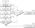
도 6은 본 발명의 일 실시예에 따른 배터리팩의 이상여부 진단 방법을 나타내는 순서도이다.
도 7은 도 6의 배터리팩의 온도 추정 방법을 나타내는 순서도이다.
도 8은 본 발명의 다른 실시예에 따른 배터리팩의 이상여부 진단 방법을 나타내는 순서도이다.
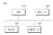
도 9는 본 발명의 일실시예에 따른 배터리 관리 시스템의 하드웨어 구성을 나타내는 블록도이다.
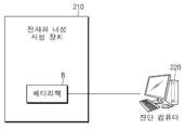
도 10은 본 발명의 일 실시예에 따른 배터리팩 진단 시스템을 나타내는 개략 구성도이다. 1 is a block diagram showing the configuration of a battery pack.
2 is a block diagram showing the configuration of a diagnosis device for an abnormality of a battery pack according to an embodiment of the present invention.
3 is a block diagram showing the configuration of the temperature estimator of FIG. 2.
4 is a graph showing on-resistance characteristic data between drain and source for a drain current of a semiconductor switching device according to an embodiment of the present invention.
5 is a graph showing On-resistance characteristic data between drain and source with respect to temperature of a semiconductor switching device according to an embodiment of the present invention.
6 is a flowchart illustrating a method for diagnosing an abnormality in a battery pack according to an embodiment of the present invention.
7 is a flowchart illustrating a method of estimating the temperature of the battery pack of FIG. 6.
8 is a flowchart illustrating a method for diagnosing an abnormality in a battery pack according to another embodiment of the present invention.
9 is a block diagram showing a hardware configuration of a battery management system according to an embodiment of the present invention.
10 is a schematic configuration diagram showing a battery pack diagnostic system according to an embodiment of the present invention.
이하, 본 발명의 일부 실시예들을 예시적인 도면을 통해 상세하게 설명한다. 각 도면의 구성요소들에 참조부호를 부가함에 있어서, 동일한 구성요소들에 대해서는 비록 다른 도면상에 표시되더라도 가능한 한 동일한 부호를 가지도록 하고 있음에 유의해야 한다. 또한, 본 발명의 실시예를 설명함에 있어서, 관련된 공지 구성 또는 기능에 대한 구체적인 설명이 본 발명의 실시예에 대한 이해를 방해한다고 판단되는 경우에는 그 상세한 설명은 생략하기로 한다.Hereinafter, some embodiments of the present invention will be described in detail through exemplary drawings. It should be noted that in adding reference numerals to the components of each drawing, the same components have the same reference numerals as possible, even if they are displayed on different drawings. In addition, in describing embodiments of the present invention, when it is determined that detailed descriptions of related well-known configurations or functions interfere with understanding of the embodiments of the present invention, detailed descriptions thereof will be omitted.
먼저, 도 1을 이용하여, 배터리팩의 구성을 간단히 설명하기로 한다. 도 1은 배터리팩의 구성을 나타내는 블록도이다. First, the configuration of the battery pack will be briefly described using FIG. 1. 1 is a block diagram showing the configuration of a battery pack.
도 1에 도시된 바와 같이, 배터리팩(B)은 하나의 이상의 배터리셀로 이루어지고, 충방전 가능한 배터리셀 모듈(1)과, 배터리셀 모듈(1)의 +단자 측 또는 -단자 측에 직렬로 연결되어 배터리셀 모듈(1)의 충방전 전류 흐름을 제어하기 위한 스위칭부(2)와, 배터리팩(B)의 전압, 전류, 온도 등을 모니터링하여, 과충전 및 과방전 등을 방지하도록 제어 관리하는 배터리 관리 시스템(3)(이하, BMS(Battery Management System)라고도 한다)을 포함한다. As shown in Figure 1, the battery pack (B) is made of one or more battery cells, a battery cell module (1) capable of charging and discharging, and the + terminal side or-terminal side of the battery cell module (1) in series Connected to the switching unit (2) for controlling the flow of charge and discharge current of the battery cell module (1), and monitors the voltage, current, temperature, etc. of the battery pack (B), and controls to prevent overcharge and overdischarge And a battery management system 3 to be managed (hereinafter also referred to as a BMS (Battery Management System)).
여기서, 스위칭부(2)는 배터리셀 모듈(1)의 충전 또는 방전에 대한 전류 흐름을 제어하기 위한 반도체 스위칭 소자로서, 예를 들면, 적어도 하나의 MOSFET이 이용될 수 있다. 구체적으로는, 스위칭부(2)에는 충전시 On으로 제어되는 충전용 스위칭 소자(2-1)와 방전시 On으로 제어되는 방전용 스위칭 소자(2-2)가 포함될 수 있다. 이러한 스위칭부(2)에 포함되는 반도체 스위칭 소자는 배터리팩(B)의 동작을 위하여 필수적으로 구비되는 구성일 수 있다. 이하에서는, 반도체 스위칭 소자로서 MOSFET이 적용된 경우를 예로 들어 설명하기로 한다. Here, the
또한, BMS(3)는, 배터리팩(B)의 전압, 전류, 온도 등을 모니터링하기 위해서, 반도체 스위칭 소자의 게이트, 소스 및 드레인 등의 전압 및 전류를 측정하거나 계산할 수 있고, 또한, 반도체 스위칭 소자에 인접해서 마련된 온도 센서(4)를 이용하여 배터리팩의 온도를 측정할 수 있다. BMS(3)는 상술한 각종 파라미터를 측정한 값을 입력받는 인터페이스로서, 복수의 단자와, 이들 단자와 연결되어 입력받은 값들의 처리를 수행하는 회로 등을 포함할 수 있다. In addition, the BMS 3 can measure or calculate voltages and currents, such as gates, sources, and drains of semiconductor switching elements, to monitor voltage, current, temperature, etc. of the battery pack B, and also semiconductor switching The temperature of the battery pack can be measured using the
일례로, BMS(3)는, 반도체 스위칭 소자가 충전 전류 흐름을 제어하기 위한 MOSFET(2-1)의 소스 단자와 방전 전류 흐름을 제어하기 위한 MOSFET(2-2)의 소스 단자가 직렬 연결된 구조로 이루어진 경우에, 단자 T1을 반도체 스위칭 소자의 일측 단자, 즉, 배터리셀 모듈(1)의 일단에 연결된 단자에 연결하고, 단자 T2를 2개의 MOSFET 사이의 단자, 즉, 소스 단자에 연결하며, 단자 T3를 반도체 스위칭 소자의 타측 단자, 즉, 배터리팩(B)의 단자 측에 연결된 단자에 연결하여, 반도체 스위칭 소자의 양단 전압 및 중간 전압을 측정할 수 있다. 이러한 방식으로 용도에 따라 반도체 스위칭 소자의 필요한 단자 혹은 위치에 연결하여 전압 및 전류 등을 측정하거나 계산할 수 있다. 또한, BMS(3)는, 단자 T4 및 T5를 각 온도 센서(4)에 연결하여 온도를 측정할 수 있다. 한편, BMS(3)는, 단자 T6 및 T7을 각 MOSFET의 게이트 단자에 연결하여 MOSFET의 ON/OFF를 제어할 수도 있으며, 배터리셀 모듈(1)에 연결되어 배터리셀 모듈(1)의 상태를 감시할 수 있다. In one example, the BMS 3 has a structure in which the semiconductor switching element is connected in series with the source terminal of the MOSFET 2-1 for controlling the charge current flow and the source terminal of the MOSFET 2-2 for controlling the discharge current flow. In the case consisting of, connect the terminal T1 to one terminal of the semiconductor switching element, that is, a terminal connected to one end of the
이와 같은 배터리팩(B)의 구성 및 BMS(3)의 구성은 공지된 구성이므로, 보다 구체적인 설명은 생략하기로 한다. Since the configuration of the battery pack B and the configuration of the BMS 3 are well known, detailed descriptions thereof will be omitted.
이어서, 도 2 및 도 3을 이용하여, 본 발명의 일 실시예에 따른 배터리팩의 이상여부 진단 장치를 설명하기로 한다. 도 2는 본 발명의 일 실시예에 따른 배터리팩의 이상여부 진단 장치의 구성을 나타내는 블록도이고, 도 3은 도 2의 온도 추정부의 구성을 나타내는 블록도이다. Next, using FIG. 2 and FIG. 3, the apparatus for diagnosing an abnormality of a battery pack according to an embodiment of the present invention will be described. FIG. 2 is a block diagram showing the configuration of an apparatus for diagnosing an abnormality of a battery pack according to an embodiment of the present invention, and FIG. 3 is a block diagram showing the configuration of a temperature estimator of FIG. 2.
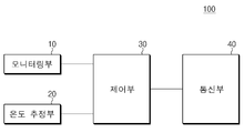
도 2에 도시된 바와 같이, 본 발명의 일 실시예에 따른 배터리팩의 이상여부 진단 장치(100)는, 모니터링부(10), 온도 추정부(20) 및 제어부(30)를 포함한다. As illustrated in FIG. 2, the
모니터링부(10)는 배터리팩 내부에 마련된 온도 센서의 측정온도를 모니터링하는 구성이다. 온도 센서는 예를 들면, 도 1에서와 같이, 배터리팩 내부에 마련된 스위칭부(2) 즉 반도체 스위칭 소자에 인접하게 마련된다. The
온도 추정부(20)는 배터리팩 내부의 반도체 스위칭 소자의 On 저항특성을 이용하여 배터리팩의 온도를 추정하는 구성이다. The
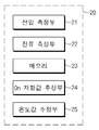
일례로, 도 3에 도시된 바와 같이, 배터리팩의 온도 추정부(20)는, 전압 측정부(21), 전류 측정부(22), 메모리(23), On 저항값 추정부(24) 및 온도값 추정부(25)를 포함할 수 있다. As an example, as shown in Figure 3, the battery pack
전압 측정부(21)는 배터리팩 내부의 반도체 스위칭 소자의 게이트-소스간 전압을 측정하는 구성이다. 여기서, 반도체 스위칭 소자는 배터리팩에 마련된 다수의 배터리셀의 충방전 전류 흐름을 제어하기 위한 스위칭 소자로서, 예를 들면, MOSFET일 수 있다. 즉, 전압 측정부(21)는 배터리팩(B) 내에 별도로 마련된 소자가 아니라, 배터리팩(B)의 동작을 위해 구비되어 있는 반도체 스위칭 소자의 전압을 측정한다. The
전류 측정부(22)는 반도체 스위칭 소자의 드레인 전류를 측정하는 구성이다. 일례로, 전류 측정부(22)는, 반도체 스위칭 소자의 드레인 전류로서, 배터리팩의 전류를 측정할 수도 있다. The
메모리(23)에는 반도체 스위칭 소자의 드레인 전류에 대한 드레인-소스간 On 저항 특성 데이터 및 반도체 스위칭 소자의 온도에 대한 드레인-소스간 On 저항 특성 데이터가 저장된다.In the
일례로, 드레인 전류에 대한 드레인-소스간 On 저항 특성 데이터는, 반도체 스위칭 소자의 게이트-소스간 전압별로 드레인 전류와 On 저항값의 관계가 미리 정의된 특성 데이터이다. 예를 들면, 도 4에 도시된 바와 같이, 반도체 스위칭 소자(예로써, MOSFET)의 게이트-소스간 전압(5V, 5.5V, 6V, 6.5V, 등)별로 드레인 전류(ID[A])와 On 저항값(RDS(ON)[mΩ])의 관계가 미리 정의된 특성 데이터일 수 있다. 비록 이와 같은 특성 데이터는 도 4에서는 그래프 형태로 나타내었으나, 표 등의 다양한 형식으로 메모리(23)에 저장될 수 있으며, 또는 관계식 등으로 정의되어 저장될 수도 있다. For example, the drain-source On-resistance characteristic data for the drain current is characteristic data in which a relationship between a drain current and an On-resistance value for each gate-source voltage of a semiconductor switching element is predefined. For example, as shown in FIG. 4, the drain current (I D [A]) for each gate-source voltage (5V, 5.5V, 6V, 6.5V, etc.) of the semiconductor switching element (eg, MOSFET) And the On resistance value (R DS (ON)[mΩ]) may be predefined characteristic data. Although such characteristic data is shown in a graph form in FIG. 4, it may be stored in the
또한, 반도체 스위칭 소자의 온도에 대한 드레인-소스간 On 저항 특성 데이터는, 반도체 스위칭 소자의 게이트-소스간 전압별로 온도와 On 저항값의 관계가 미리 정의된 특성 데이터이다. 예를 들면, 도 5에 도시된 바와 같이, 반도체 스위칭 소자(예로써, MOSFET)의 게이트-소스간 전압별로 온도(Tj[℃])와 On 저항값(RDS(ON)[mΩ])의 관계가 미리 정의된 특성 데이터일 수 있다. 비록, 도 5에서는 게이트-소스간 전압으로서 5V인 경우를 예로 들어 나타내었으나, 다른 게이트-소스간 전압별로도 각각 나타낼 수 있다. 비록 이와 같은 특성 데이터는 도 5에서는 그래프 형태로 나타내었으나, 표 등의 다양한 형식으로 메모리(23)에 저장될 수 있으며, 또는 관계식 등으로 정의되어 저장될 수도 있다. In addition, the drain-source On resistance characteristic data with respect to the temperature of the semiconductor switching element is characteristic data in which the relationship between the temperature and the On resistance value for each gate-source voltage of the semiconductor switching element is predefined. For example, as shown in FIG. 5, the temperature (T j [°C]) and the On resistance value (R DS (ON) [mΩ]) for each gate-source voltage of the semiconductor switching element (eg, MOSFET). The relationship of may be predefined characteristic data. Although, in FIG. 5, a case of 5V as the voltage between the gate and the source is shown as an example, it may also be indicated for each voltage between the other gate and sources. Although such characteristic data is shown in a graph form in FIG. 5, it may be stored in the
On 저항값 추정부(24)는, 전압 측정부(21)에서 측정한 전압값, 전류 측정부(22)에서 측정한 전류값 및 메모리(23)에 저장된 반도체 스위칭 소자의 드레인 전류에 대한 드레인-소스간 On 저항 특성 데이터를 이용하여, 반도체 스위칭 소자의 측정된 드레인 전류에 대한 드레인-소스간 On 저항값을 추정한다. The on-
온도값 추정부(25)는 On 저항값 추정부(24)에 의하여 추정된 On 저항값과 메모리(23)에 저장된 반도체 스위칭 소자의 온도에 대한 드레인-소스간 On 저항 특성 데이터를 이용하여, 반도체 스위칭 소자의 추정된 On 저항값에 대한 온도를 추정한다. The
이와 같이 하여, 온도 추정부(20)는 배터리팩 내부의 반도체 스위칭 소자의 On 저항특성을 이용하여 배터리팩의 온도를 추정할 수 있다. In this way, the
다시 도 2로 돌아가서, 제어부(30)는 측정온도의 변화폭이 미리 설정된 변화 조건을 만족하지 않는 경우, 온도 센서의 측정온도와 추정된 온도의 온도차에 기초하여, 온도 센서의 이상여부를 진단하는 구성이다. 여기서, 측정온도의 변화폭에 대한 미리 설정된 변화 조건은, 배터리팩의 전자파 내성(RI; Radiated Immunity) 시험시 노이즈 유입에 의해 측정되는 변화폭에 기초하여 미리 설정될 수 있다. 예를 들어, 전자파 내성 시험에 의해 배터리팩(B)에 전자파가 방사될 때, 방사된 전자파에 의해 발생한 노이즈의 크기가 미리 설정된 변화 조건보다 크면 온도 센서의 이상 여부를 진단하도록 상기 변화 조건을 설정할 수 있다. 그리고, 제어부(30)는 온도 센서의 측정온도와 추정된 온도의 온도차가 소정 범위를 만족하는지 판단하여, 해당 온도차가 소정 범위를 만족하지 않으면 온도 센서가 이상이라고 진단할 수 있다. Returning to FIG. 2 again, the
추가로, 도 2에서와 같이, 본 발명의 일 실시예에 따른 배터리팩의 이상여부 진단 장치(100)는, 예를 들면, 외부와 유선 또는 무선으로 통신가능한 통신부(40)를 더 구비할 수 있다. In addition, as shown in FIG. 2, the
일례로, 제어부(30)는, 온도차가 소정범위를 만족하지 않는 횟수가 미리 설정된 기준 횟수를 연속 초과하는 경우, 통신부(40)를 통해 외부로 경고 신호를 송신할 수 있다. In one example, the
일례로, 본 발명의 일 실시예에 따른 배터리팩의 이상여부 진단 장치(100)는, 배터리팩 내부의 배터리 관리 시스템(BMS)의 일부 구성으로서 구현될 수 있다. For example, the
이와 같은 본 발명에 의하면, 배터리팩의 EMC 시험 등에 있어서 자체적으로 배터리팩 내부에 마련된 온도 센서의 노이즈 유입에 의한 이상을 진단하고 외부로 경고 신호를 송신할 수 있다. According to the present invention, it is possible to diagnose an abnormality due to noise inflow of a temperature sensor provided inside the battery pack and transmit a warning signal to the outside in the EMC test of the battery pack.
이어서, 도 6 및 도 7을 이용하여, 본 발명의 일 실시예에 따른 배터리팩의 이상여부 진단 방법을 설명하기로 한다. 도 6은 본 발명의 일 실시예에 따른 배터리팩의 이상여부 진단 방법을 나타내는 순서도이고, 도 7는 도 6의 배터리팩의 온도 추정 방법을 나타내는 순서도이다. Next, a method for diagnosing an abnormality of a battery pack according to an embodiment of the present invention will be described with reference to FIGS. 6 and 7. 6 is a flowchart illustrating a method for diagnosing an abnormality in a battery pack according to an embodiment of the present invention, and FIG. 7 is a flowchart illustrating a method for estimating temperature of the battery pack in FIG. 6.
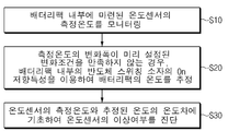
먼저, 도 6에 도시된 바와 같이, 본 발명의 일 실시예에 따른 배터리팩의 이상여부 진단 방법은, 배터리팩 내부에 마련된 온도 센서의 측정온도를 실시간으로 모니터링한다(S10). 여기서, 배터리팩(B)의 모니터링은 배터리팩(B) 출하전의 각종 EMC 시험 중에 수행되는 것일 수 있다. 예를 들어, EMC 시험은 전자파 내성 시험일 수 있다. 그러나, 이는 예시일 뿐, 이에 한정되지 않으며 배터리팩(B) 출하 후에 본 방법이 실시될 수도 있을 것이다. First, as illustrated in FIG. 6, in the method for diagnosing an abnormality of a battery pack according to an embodiment of the present invention, the measurement temperature of the temperature sensor provided inside the battery pack is monitored in real time (S10). Here, the monitoring of the battery pack (B) may be performed during various EMC tests before shipping the battery pack (B). For example, the EMC test can be an electromagnetic immunity test. However, this is only an example, and is not limited thereto, and the method may be implemented after the battery pack B is shipped.
모니터링시, 측정온도의 변화폭이 미리 설정된 변화 조건을 만족하지 않는 경우, 배터리팩 내부의 반도체 스위칭 소자의 On 저항특성을 이용하여 배터리팩의 온도를 추정한다(S20). 여기서, 측정온도의 변화폭에 대한 미리 설정된 변화 조건은, 예를 들면, 배터리팩의 전자파 내성 시험시 노이즈 유입에 의해 측정되는 변화폭에 기초하여 설정될 수 있다. When monitoring, if the change width of the measured temperature does not satisfy the preset change condition, the temperature of the battery pack is estimated by using the On resistance characteristic of the semiconductor switching element inside the battery pack (S20). Here, the preset change condition for the change width of the measurement temperature may be set based on, for example, a change width measured by the inflow of noise during the electromagnetic immunity test of the battery pack.
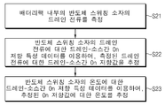
일례로, 배터리팩의 온도를 추정하는 단계(S20)는, 도 7에 도시된 바와 같은 과정을 거쳐서 온도를 추정할 수 있다. 예를 들면, 먼저, 배터리팩 내부의 반도체 스위칭 소자의 드레인 전류를 측정한다(S21). 이어서, 반도체 스위칭 소자의 드레인 전류에 대한 드레인-소스간 On 저항 특성 데이터를 이용하여, 측정된 드레인 전류에 대한 드레인-소스간 On 저항값을 추정하고(S22), 반도체 스위칭 소자의 온도에 대한 드레인-소스간 On 저항 특성 데이터를 이용하여, 추정된 On 저항값에 대한 온도를 추정한다(S23). For example, in the step of estimating the temperature of the battery pack (S20), the temperature may be estimated through a process as illustrated in FIG. 7. For example, first, the drain current of the semiconductor switching element inside the battery pack is measured (S21). Subsequently, by using the drain-to-source On-resistance characteristic data for the drain current of the semiconductor switching device, the drain-to-source On resistance value for the measured drain current is estimated (S22), and the drain for the temperature of the semiconductor switching device is calculated. -Using the on-resistance characteristic data between sources, the temperature for the estimated On-resistance value is estimated (S23).
다시 도 6으로 돌아가서, 본 발명의 일 실시예에 따른 배터리팩의 이상여부 진단 방법은, 온도 센서의 측정온도와 추정된 온도의 온도차에 기초하여 온도 센서의 이상여부를 진단한다(S30). 예로써, 온도 센서의 측정온도와 추정된 온도의 온도차가 소정 범위를 만족하는지 판단하여, 해당 온도차가 소정 범위를 만족하지 않으면 온도 센서가 이상이라고 진단할 수 있다. 이에 따라, 기존에 측정하던 값들을 이용하여 온도 센서의 이상 현상을 진단할 수 있다. Returning to FIG. 6 again, the method for diagnosing an abnormality of a battery pack according to an embodiment of the present invention diagnoses an abnormality of the temperature sensor based on a temperature difference between the measured temperature of the temperature sensor and the estimated temperature (S30). For example, it is determined whether the temperature difference between the measured temperature of the temperature sensor and the estimated temperature satisfies a predetermined range, and if the temperature difference does not satisfy the predetermined range, the temperature sensor may be diagnosed as abnormal. Accordingly, the abnormality of the temperature sensor can be diagnosed using the previously measured values.
이어서, 도 8을 이용하여, 본 발명의 다른 실시예에 따른 배터리팩의 이상여부 진단 방법을 설명하기로 한다. 도 8은 본 발명의 다른 실시예에 따른 배터리팩의 이상여부 진단 방법을 나타내는 순서도이다. Next, with reference to FIG. 8, a method for diagnosing an abnormality of a battery pack according to another embodiment of the present invention will be described. 8 is a flowchart illustrating a method for diagnosing an abnormality in a battery pack according to another embodiment of the present invention.
도 8에 도시된 바와 같이, 본 발명의 다른 실시예에 따른 배터리팩의 이상여부 진단 방법은, 먼저, 배터리팩 내부에 마련된 온도 센서에 의해 측정되는 온도를 모니터링하여, 온도 센서의 측정 온도에서 흔들림이 발생하는 것을 감지하면(S110), 배터리팩 내부의 반도체 스위칭 소자의 드레인 전류로서 배터리팩의 전류를 측정한다(S120). As illustrated in FIG. 8, in the method for diagnosing an abnormality of a battery pack according to another embodiment of the present invention, first, the temperature measured by the temperature sensor provided inside the battery pack is monitored and shaken at the measured temperature of the temperature sensor When detecting that this occurs (S110), the current of the battery pack is measured as the drain current of the semiconductor switching element inside the battery pack (S120).
이어서, 예를 들면, 도 4와 같은 반도체 스위칭 소자의 드레인 전류에 대한 드레인-소스간 On 저항 특성 데이터를 이용하여, 측정된 배터리팩의 전류에 대한 드레인-소스간 On 저항값(RDS(ON))을 추정한다(S130). 예를 들면, 측정된 반도체 스위칭 소자의 드레인 전류에 대응하는 On 저항값을 추정값으로 이용할 수 있다. Subsequently, for example, by using the drain-source On-resistance characteristic data for the drain current of the semiconductor switching device as shown in FIG. 4, the measured drain-source On resistance value for the current of the battery pack (R DS(ON ) ) Is estimated (S130 ). For example, an On resistance value corresponding to the measured drain current of the semiconductor switching element can be used as an estimated value.
이어서, 예를 들면, 도 5와 같은 반도체 스위칭 소자의 온도에 대한 드레인-소스간 On 저항 특성 데이터를 이용하여, 추정된 On 저항값에 대한 온도를 추정한다(S140). 예를 들면, 추정된 On 저항값에 대응하는 온도값을 추정값으로 이용할 수 있다. Subsequently, for example, the temperature for the estimated On resistance value is estimated using the On-resistance characteristic data between the drain and the source for the temperature of the semiconductor switching device as shown in FIG. 5 (S140). For example, a temperature value corresponding to the estimated On resistance value can be used as the estimated value.
이어서, 온도 센서에 의해 측정된 온도와 추정된 온도의 온도차가 소정범위를 만족하는지 판단한다(S150). 만일, 온도차가 소정범위를 만족하지 않는 것으로 판단하면(NO)), 온도차가 소정범위를 만족하지 않는 횟수가 미리 설정된 기준 횟수(예로써, 5회)를 연속 초과하는지 판단한다(S155). 기준 횟수를 연속 초과하지 않은 경우에는 배터리팩의 전류를 측정하는 단계(S120)로 이동하고, 기준 횟수를 연속 초과한 경우에는, 온도 센서에 이상이 있다고 진단하여, 소정의 경고 신호를 발생시킨다(S160). 한편, 온도차가 소정범위를 만족하는 것으로 판단하면(YES), 온도 센서에 이상이 없는 것으로 진단하고(S170), 모니터링을 계속한다.Next, it is determined whether a temperature difference between the temperature measured by the temperature sensor and the estimated temperature satisfies a predetermined range (S150). If it is determined that the temperature difference does not satisfy the predetermined range (NO), it is determined whether the number of times the temperature difference does not satisfy the predetermined range continuously exceeds a preset reference number (for example, 5 times) (S155). If the reference number of times is not continuously exceeded, the process moves to step S120 of measuring the current of the battery pack. If the reference number of times is continuously exceeded, the temperature sensor is diagnosed as having an abnormality, and a predetermined warning signal is generated ( S160). On the other hand, if it is determined that the temperature difference satisfies the predetermined range (YES), the temperature sensor is diagnosed as having no abnormality (S170), and monitoring is continued.
이와 같은 본 발명에 의하면, 배터리팩의 EMC 시험 등에 있어서 배터리팩 내부에 마련된 온도 센서의 노이즈 유입에 의한 이상을 진단할 수 있다.According to the present invention, an abnormality due to noise inflow of the temperature sensor provided inside the battery pack can be diagnosed in the EMC test of the battery pack.
한편, 상술한 설명에서는 배터리팩의 이상여부 진단 장치 및 방법을 설명하였으나, 본 발명은 배터리팩의 온도 추정 장치 및 방법으로서 구현될 수도 있다. On the other hand, in the above description, the apparatus and method for diagnosing an abnormality of a battery pack have been described, but the present invention may be implemented as an apparatus and method for estimating a temperature of a battery pack.
예를 들면, 본 발명의 일실시예에 따른 배터리팩의 온도 추정 장치는, 도 3의 온도 추정부(20)와 같이, 전압 측정부(21)는 배터리팩 내부의 반도체 스위칭 소자의 게이트-소스간 전압을 측정하는 전압 측정부(21)와, 반도체 스위칭 소자의 드레인 전류를 측정하는 전류 측정부(22)와, 반도체 스위칭 소자의 드레인 전류에 대한 드레인-소스간 On 저항 특성 데이터 및 반도체 스위칭 소자의 온도에 대한 드레인-소스간 On 저항 특성 데이터가 저장된 메모리(23)와, 반도체 스위칭 소자의 드레인 전류에 대한 드레인-소스간 On 저항 특성 데이터를 이용하여, 측정된 드레인 전류에 대한 드레인-소스간 On 저항값을 추정하는 On 저항값 추정부(24)와, 반도체 스위칭 소자의 온도에 대한 드레인-소스간 On 저항 특성 데이터를 이용하여, 추정된 On 저항값에 대한 온도를 추정하는 온도값 추정부(25)를 포함하여 구성될 수 있다. 일례로, 전류 측정부(22)는, 반도체 스위칭 소자의 드레인 전류로서, 배터리팩의 전류를 측정할 수 있다. For example, the temperature estimation device of the battery pack according to an embodiment of the present invention, as the
여기서, 드레인 전류에 대한 드레인-소스간 On 저항 특성 데이터는, 반도체 스위칭 소자의 게이트-소스간 전압별로 드레인 전류와 On 저항값의 관계가 미리 정의된 특성 데이터이며, 반도체 스위칭 소자의 온도에 대한 드레인-소스간 On 저항 특성 데이터는, 반도체 스위칭 소자의 게이트-소스간 전압별로 온도와 On 저항값의 관계가 미리 정의된 특성 데이터이다.Here, the drain-source on-resistance characteristic data for the drain current is a characteristic data in which a relationship between a drain current and an on-resistance value for each gate-source voltage of the semiconductor switching element is predefined, and a drain for a temperature of the semiconductor switching element. -On-resistance characteristic data between sources is a characteristic data in which a relationship between a temperature and an On-resistance value for each gate-source voltage of a semiconductor switching element is predefined.
또한, 본 발명의 일 실시예에 따른 배터리팩의 온도 추정 방법은, 도 7에 도시된 바와 같이, 예를 들면, 배터리팩 내부의 반도체 스위칭 소자의 드레인 전류를 측정한다(S21). 이어서, 반도체 스위칭 소자의 드레인 전류에 대한 드레인-소스간 On 저항 특성 데이터를 이용하여, 측정된 드레인 전류에 대한 드레인-소스간 On 저항값을 추정한다(S22). 이어서, 반도체 스위칭 소자의 온도에 대한 드레인-소스간 On 저항 특성 데이터를 이용하여, 추정된 On 저항값에 대한 온도를 추정한다(S23). In addition, in the method for estimating the temperature of a battery pack according to an embodiment of the present invention, as illustrated in FIG. 7, for example, a drain current of a semiconductor switching element inside the battery pack is measured (S21). Subsequently, the On-to-Drain-Source resistance value for the measured drain current is estimated using the On-to-Drain on-resistance characteristic data for the drain current of the semiconductor switching device (S22 ). Subsequently, the temperature of the estimated On resistance value is estimated using the On-resistance characteristic data between the drain and the source with respect to the temperature of the semiconductor switching device (S23 ).
이에 따라, 배터리팩 내부에 온도 센서를 마련하지 않아도, 배터리팩 내부에 마련된 반도체 스위칭 소자의 On 저항 특성을 이용하여 배터리팩의 온도를 측정할 수 있다. Accordingly, even if a temperature sensor is not provided inside the battery pack, the temperature of the battery pack can be measured by using the On resistance characteristic of the semiconductor switching device provided inside the battery pack.
일 실시예로서, 상술한 본 발명의 일 실시예에 따른 배터리팩의 이상여부 진단 방법 혹은 배터리팩의 온도 추정 방법은, 각 단계를 수행하는 기록 매체에 저장된 프로그램으로 구현될 수 있으며, 해당 프로그램은 배터리팩의 BMS의 메모리에 저장되고 MCU에 의해 실행될 수 있다. 다시 말해, 본 발명의 방법은 컴퓨터 프로그램으로 작성이 가능하다. 그리고 상기 프로그램을 구성하는 코드 및 코드 세그먼트는 당해 분야의 컴퓨터 프로그래머에 의하여 용이하게 추론될 수 있다. 또한, 상기 작성된 프로그램은 컴퓨터가 읽을 수 있는 기록 매체(정보 저장 매체)에 저장되고, 컴퓨터에 의하여 판독되고 실행됨으로써 본 발명의 방법을 실현할 수 있다. 그리고 상기 기록 매체는 컴퓨터가 판독할 수 있는 모든 형태의 기록매체를 포함한다. 상기 기록 매체는 MCU와 별도로 마련될 수도 있으나, MCU와 일체로 형성된 구성일 수도 있을 것이다. As an embodiment, the method for diagnosing an abnormality of a battery pack or a method for estimating a temperature of a battery pack according to an embodiment of the present invention described above may be implemented as a program stored in a recording medium that performs each step. It is stored in the memory of the BMS of the battery pack and can be executed by the MCU. In other words, the method of the present invention can be created with a computer program. In addition, codes and code segments constituting the program can be easily inferred by a computer programmer in the field. Further, the created program is stored in a computer-readable recording medium (information storage medium), and can be read and executed by a computer to realize the method of the present invention. In addition, the recording medium includes any form of computer-readable recording media. The recording medium may be provided separately from the MCU, but may be configured integrally with the MCU.
예를 들면, 본 발명의 배터리팩의 BMS는 도 9와 같이 구현될 수 있다. 도 9는 본 발명의 일실시예에 따른 배터리 관리 시스템(BMS)의 하드웨어 구성을 나타내는 블록도이다.For example, the BMS of the battery pack of the present invention may be implemented as shown in FIG. 9. 9 is a block diagram showing a hardware configuration of a battery management system (BMS) according to an embodiment of the present invention.
도 9에 도시된 바와 같이, 배터리 관리 시스템(300)은, 각종 처리 및 각 구성을 제어하는 마이크로컨트롤러(MCU; 310)와, 운영체제 프로그램 및 각종 프로그램(예로서, 배터리팩의 이상여부 진단 프로그램 혹은 배터리팩의 온도 추정 프로그램) 등이 기록되는 메모리(320)와, 배터리셀 모듈 및/또는 반도체 스위칭 소자와의 사이에서 입력 인터페이스 및 출력 인터페이스를 제공하는 입출력 인터페이스(330)와, 유무선 통신망을 통해 외부와 통신 가능한 통신 인터페이스(340)를 구비할 수 있다. 이와 같이, 본 발명에 따른 컴퓨터 프로그램은 메모리(320)에 기록되고, 마이크로 컨트롤러(310)에 의해 처리됨으로써 예를 들면 도 2 및 도 3에서 도시한 각 기능 블록들을 수행하는 모듈로서 구현될 수 있다. As illustrated in FIG. 9, the
또 다른 실시예로서, 도 10을 이용하여 본 발명의 일 실시예에 따른 배터리팩 진단 시스템을 설명하기로 한다. 도 10은 본 발명의 일 실시예에 따른 배터리팩 진단 시스템을 나타내는 개략 구성도이다. As another embodiment, a battery pack diagnostic system according to an embodiment of the present invention will be described with reference to FIG. 10. 10 is a schematic configuration diagram showing a battery pack diagnostic system according to an embodiment of the present invention.
도 10에 도시된 바와 같이, 본 발명의 일 실시예에 따른 배터리팩 진단 시스템은, 전자파 내성 시험 장치(210) 및 진단 컴퓨터(220)를 포함하여 구성될 수 있다. As shown in FIG. 10, a battery pack diagnostic system according to an embodiment of the present invention may include an electromagnetic wave
전자파 내성 시험 장치(210)는, 전자파 내성 시험을 위해, 전자파노이즈를 발생시켜 배터리팩(B)에 방사하는 장치이다. 일례로, 전자파 내성 시험 장치(210)는, 도시하지는 않았으나, 전자파노이즈를 발생시키는 신호발생장치와, 발생된 전자파노이즈를 방사하는 안테나와, 시험공간인 챔버를 포함하여 구성될 수 있다. 이와 같은 전자파 내성 시험 장치(210)는 공지된 구성이므로 자세한 설명은 생략하기로 한다. The electromagnetic wave
진단 컴퓨터(220)는, 전자파노이즈가 방사되는 배터리팩(B), 예를 들면, 배터리팩(B)의 BMS에 연결되어, 전자파노이즈가 방사될 때, 배터리팩 내부의 온도 센서로부터 측정되는 온도와, 배터리팩 내부의 반도체 스위칭 소자에 대하여 측정된 전압, 전류 및 On 저항특성에 기초하여 추정되는 온도와, 전자파노이즈가 방사되는 타이밍에 기초하여 배터리팩의 전자파 내성을 진단할 수 있으며, 전자파노이즈가 방사되는 타이밍에서의 배터리팩(B)의 온도 센서의 이상여부를 진단할 수 있다The
이에 따라, 배터리팩의 내부의 BMS에서 자체적으로 배터리팩의 이상여부를 진단하는 것만이 아니라, 배터리팩의 외부에서 전자파 내성 시험시 배터리팩 내부에 마련된 온도센서의 이상 여부를 진단할 수 있고, 나아가서, 전자파 내성 시험시 수집된 데이터를 다양한 분석 및 평가에 활용할 수도 있다. Accordingly, the BMS inside the battery pack can not only diagnose whether the battery pack itself is abnormal, but also can diagnose whether the temperature sensor provided inside the battery pack is abnormal when testing electromagnetic immunity from the outside of the battery pack. In addition, data collected during the electromagnetic immunity test may be used for various analysis and evaluation.
다른 예로서, 배터리팩(B)의 BMS(3)가 온도 추정 및 이상 여부의 진단을 모두 또는 일부 수행하고, 진단 컴퓨터(22)는 배터리팩(B)의 BMS(3)로부터 이상 여부 및 이상 발생시 경고 신호 등을 수신하거나 일부 진단 동작을 수행하는 것으로 구성할 수도 있을 것이다. As another example, the BMS 3 of the battery pack B performs all or part of the diagnosis of the temperature estimation and the abnormality, and the
이상에서 본 발명은 비록 한정된 실시예와 도면에 의해 설명되었으나, 본 발명은 이것에 의해 한정되지 않으며, 본 발명이 속하는 기술분야에서 통상의 지식을 가진 자에 의해 본 발명의 기술사상과 아래에 기재될 특허청구범위의 균등범위 내에서 다양한 실시가 가능함은 물론이다.Although the present invention has been described above by way of limited examples and drawings, the present invention is not limited by this, and is described below by the person skilled in the art to which the present invention pertains and the technical idea of the present invention. Of course, various implementations are possible within the equal scope of the claims to be made.
B: 배터리팩
1: 배터리셀 모듈
2: 스위칭부
3: 배터리 관리 시스템(BMS)
10: 모니터링부
20: 온도 추정부
21: 전압 측정부
22: 전류 측정부
23: 메모리
24: On 저항값 추정부
25: 온도값 추정부
30: 제어부
40: 통신부
210: 전자파 내성 시험 장치
220: 진단 컴퓨터
300: 배터리 관리 시스템(BMS)
310: 마이크로 컨트롤러(MCU)
320: 메모리
330: 입출력 인터페이스
340: 통신 인터페이스B: Battery pack 1: Battery cell module
2: Switching unit 3: Battery management system (BMS)
10: monitoring unit 20: temperature estimation unit
21: voltage measuring unit 22: current measuring unit
23: Memory 24: On resistance value estimator
25: temperature value estimator 30: control unit
40: communication unit 210: electromagnetic immunity test device
220: diagnostic computer 300: battery management system (BMS)
310: microcontroller (MCU) 320: memory
330: input and output interface 340: communication interface
Claims (16)
상기 반도체 스위칭 소자의 드레인 전류에 대한 드레인-소스간 On 저항 특성 데이터를 이용하여, 상기 측정된 드레인 전류에 대한 드레인-소스간 On 저항값을 추정하는 단계; 및
상기 반도체 스위칭 소자의 온도에 대한 드레인-소스간 On 저항 특성 데이터를 이용하여, 상기 추정된 On 저항값에 대한 온도를 추정하는 단계를 포함하는 배터리팩의 온도 추정 방법.Measuring a drain current of the semiconductor switching element inside the battery pack;
Estimating a drain-source On resistance value for the measured drain current by using On-Drain-Source On-resistance characteristic data for the drain current of the semiconductor switching device; And
And estimating a temperature for the estimated On resistance value by using On-drain characteristic data between drain and source for the temperature of the semiconductor switching element.
상기 반도체 스위칭 소자는, 상기 배터리팩에 마련된 다수의 배터리셀의 충방전 전류 흐름을 제어하기 위한 스위칭 소자인 배터리팩의 온도 추정 방법.The method according to claim 1,
The semiconductor switching element is a method for estimating the temperature of a battery pack, which is a switching element for controlling the flow of charge and discharge currents of a plurality of battery cells provided in the battery pack.
상기 반도체 스위칭 소자는, MOSFET인 배터리팩의 온도 추정 방법.The method according to claim 1,
The semiconductor switching element, MOSFET battery pack temperature estimation method.
상기 드레인 전류에 대한 드레인-소스간 On 저항 특성 데이터는, 상기 반도체 스위칭 소자의 게이트-소스간 전압별로 상기 드레인 전류와 On 저항값의 관계가 미리 정의된 특성 데이터인 배터리팩의 온도 추정 방법.The method according to claim 1,
The drain-source On-resistance characteristic data for the drain current is a method of estimating a temperature of a battery pack in which a relationship between the drain current and an On-resistance value is predefined for each gate-source voltage of the semiconductor switching device.
상기 반도체 스위칭 소자의 온도에 대한 드레인-소스간 On 저항 특성 데이터는, 상기 반도체 스위칭 소자의 게이트-소스간 전압별로 상기 온도와 On 저항값의 관계가 미리 정의된 특성 데이터인 배터리팩의 온도 추정 방법.The method according to claim 1,
The drain-source On-resistance characteristic data for the temperature of the semiconductor switching element is a method for estimating the temperature of the battery pack, wherein the relationship between the temperature and the On-resistance value for each gate-source voltage of the semiconductor switching element is predefined characteristic data. .
상기 반도체 스위칭 소자의 드레인 전류를 측정하는 단계는, 드레인 전류로서 배터리팩의 전류를 측정하는 배터리팩의 온도 추정 방법.The method according to claim 2,
The step of measuring the drain current of the semiconductor switching element is a method of estimating the temperature of the battery pack that measures the current of the battery pack as the drain current.
상기 반도체 스위칭 소자의 드레인 전류를 측정하는 전류 측정부;
상기 반도체 스위칭 소자의 드레인 전류에 대한 드레인-소스간 On 저항 특성 데이터 및 상기 반도체 스위칭 소자의 온도에 대한 드레인-소스간 On 저항 특성 데이터가 저장된 메모리;
상기 반도체 스위칭 소자의 드레인 전류에 대한 드레인-소스간 On 저항 특성 데이터를 이용하여, 상기 측정된 드레인 전류에 대한 드레인-소스간 On 저항값을 추정하는 On 저항값 추정부; 및
상기 반도체 스위칭 소자의 온도에 대한 드레인-소스간 On 저항 특성 데이터를 이용하여, 상기 추정된 On 저항값에 대한 온도를 추정하는 온도값 추정부를 포함하는 배터리팩의 온도 추정 장치.A voltage measuring unit for measuring a gate-source voltage of the semiconductor switching element inside the battery pack;
A current measuring unit measuring a drain current of the semiconductor switching element;
A memory storing drain-source On resistance characteristic data for a drain current of the semiconductor switching element and drain-source On resistance characteristic data for a temperature of the semiconductor switching element;
An On-resistance value estimator for estimating the On-resistance value between the drain-sources for the measured drain currents using the On-to-Drain resistance data of the semiconductor switching device; And
And a temperature value estimator for estimating a temperature for the estimated On resistance value by using the drain-source On resistance characteristic data for the temperature of the semiconductor switching element.
상기 측정온도의 변화폭이 미리 설정된 변화 조건을 만족하지 않는 경우, 상기 배터리팩 내부의 반도체 스위칭 소자의 On 저항특성을 이용하여 배터리팩의 온도를 추정하는 단계; 및
상기 온도 센서의 측정온도와 상기 추정된 온도의 온도차에 기초하여 상기 온도 센서의 이상여부를 진단하는 단계를 포함하는 배터리팩의 이상여부 진단 방법.Monitoring the measured temperature of the temperature sensor provided inside the battery pack;
Estimating the temperature of the battery pack by using the On resistance characteristic of the semiconductor switching element inside the battery pack when the variation range of the measured temperature does not satisfy a preset change condition; And
And diagnosing whether the temperature sensor is abnormal based on a temperature difference between the measured temperature of the temperature sensor and the estimated temperature.
상기 배터리팩의 온도를 추정하는 단계는,
상기 배터리팩 내부의 반도체 스위칭 소자의 드레인 전류를 측정하는 단계;
상기 반도체 스위칭 소자의 드레인 전류에 대한 드레인-소스간 On 저항 특성 데이터를 이용하여, 상기 측정된 드레인 전류에 대한 드레인-소스간 On 저항값을 추정하는 단계; 및
상기 반도체 스위칭 소자의 온도에 대한 드레인-소스간 On 저항 특성 데이터를 이용하여, 상기 추정된 On 저항값에 대한 온도를 추정하는 단계를 포함하는 배터리팩의 이상여부 진단 방법.The method according to claim 8,
Estimating the temperature of the battery pack,
Measuring a drain current of the semiconductor switching element inside the battery pack;
Estimating a drain-source On resistance value for the measured drain current by using On-Drain-Source On-resistance characteristic data for the drain current of the semiconductor switching device; And
And estimating a temperature for the estimated On resistance value using the On-resistance characteristic data between drain and source for the temperature of the semiconductor switching element.
상기 반도체 스위칭 소자는, 상기 배터리팩에 마련된 다수의 배터리셀의 충방전 전류 흐름을 제어하기 위한 스위칭 소자인 배터리팩의 이상여부 진단 방법.The method according to claim 8,
The semiconductor switching element is a switching element for controlling the flow of charge and discharge currents of a plurality of battery cells provided in the battery pack.
상기 반도체 스위칭 소자는, MOSFET인 배터리팩의 이상여부 진단 방법.The method according to claim 8,
The semiconductor switching element, the method of diagnosing whether the battery pack is a MOSFET.
상기 온도차가 소정범위를 만족하지 않는 횟수가 미리 설정된 기준 횟수를 연속 초과하는 경우, 경고 신호를 발생시키는 단계를 더 포함하는 배터리팩의 이상여부 진단 방법.The method according to claim 8,
When the number of times the temperature difference does not satisfy the predetermined range continuously exceeds a preset reference number, generating a warning signal further comprising the step of generating a warning signal.
상기 미리 설정된 변화 조건은, 상기 배터리팩의 전자파 내성 시험시 노이즈 유입에 의해 측정되는 변화폭에 기초하여 설정되는 배터리팩의 이상여부 진단 방법.The method according to claim 8,
The preset change condition is a method for diagnosing an abnormality of a battery pack, which is set based on a change width measured by noise inflow during the electromagnetic immunity test of the battery pack.
상기 배터리팩 내부의 반도체 스위칭 소자의 On 저항특성을 이용하여 배터리팩의 온도를 추정하는 온도 추정부; 및
상기 측정온도의 변화폭이 미리 설정된 변화 조건을 만족하지 않는 경우, 상기 온도 센서의 측정온도와 상기 추정된 온도의 온도차에 기초하여, 상기 온도 센서의 이상여부를 진단하는 제어부를 포함하는 배터리팩의 이상여부 진단 장치.Monitoring unit for monitoring the measurement temperature of the temperature sensor provided inside the battery pack;
A temperature estimator for estimating the temperature of the battery pack by using the On resistance characteristic of the semiconductor switching element inside the battery pack; And
When the change width of the measured temperature does not satisfy a preset change condition, the battery pack includes a control unit configured to diagnose whether the temperature sensor is abnormal based on a difference between the measured temperature of the temperature sensor and the estimated temperature. Whether the diagnostic device.
외부와 통신가능한 통신부를 더 구비하며,
상기 제어부는, 상기 온도차가 소정범위를 만족하지 않는 횟수가 미리 설정된 기준 횟수를 연속 초과하는 경우, 통신부를 통해 외부로 경고 신호를 송신하는 배터리팩의 이상여부 진단 장치.The method according to claim 14,
It further includes a communication unit that can communicate with the outside,
The control unit, if the number of times the temperature difference does not satisfy a predetermined range continuously exceeds a preset reference number of times, the battery pack abnormality diagnosis device for transmitting a warning signal to the outside through the communication unit.
상기 전자파노이즈가 방사되는 배터리팩에 연결되어, 상기 전자파노이즈가 방사될 때, 상기 배터리팩 내부의 온도 센서로부터 측정되는 온도와, 상기 배터리팩 내부의 반도체 스위칭 소자에 대하여 측정된 전압, 전류 및 On 저항특성에 기초하여 추정되는 온도와, 상기 전자파노이즈가 방사되는 타이밍에 기초하여 상기 배터리팩의 전자파 내성을 진단하는 진단 컴퓨터를 포함하는 배터리팩 진단 시스템.For the electromagnetic immunity test, an electromagnetic immunity test device that generates electromagnetic noise and radiates the battery pack; And
When connected to a battery pack in which the electromagnetic noise is radiated, when the electromagnetic noise is radiated, temperature measured from a temperature sensor inside the battery pack, and voltage, current and on measured for a semiconductor switching element in the battery pack A battery pack diagnostic system including a diagnostic computer for diagnosing electromagnetic resistance of the battery pack based on temperature estimated based on resistance characteristics and timing at which the electromagnetic noise is emitted.
Priority Applications (1)
| Application Number | Priority Date | Filing Date | Title |
|---|---|---|---|
| KR1020190002681A KR102779857B1 (en) | 2019-01-09 | 2019-01-09 | Method and apparatus for estimating temperature of battery pack, and method and apparatus for diagnosing abnormality of battery pack |
Applications Claiming Priority (1)
| Application Number | Priority Date | Filing Date | Title |
|---|---|---|---|
| KR1020190002681A KR102779857B1 (en) | 2019-01-09 | 2019-01-09 | Method and apparatus for estimating temperature of battery pack, and method and apparatus for diagnosing abnormality of battery pack |
Publications (2)
| Publication Number | Publication Date |
|---|---|
| KR20200086471A true KR20200086471A (en) | 2020-07-17 |
| KR102779857B1 KR102779857B1 (en) | 2025-03-12 |
Family
ID=71832162
Family Applications (1)
| Application Number | Title | Priority Date | Filing Date |
|---|---|---|---|
| KR1020190002681A Active KR102779857B1 (en) | 2019-01-09 | 2019-01-09 | Method and apparatus for estimating temperature of battery pack, and method and apparatus for diagnosing abnormality of battery pack |
Country Status (1)
| Country | Link |
|---|---|
| KR (1) | KR102779857B1 (en) |
Cited By (3)
| Publication number | Priority date | Publication date | Assignee | Title |
|---|---|---|---|---|
| WO2024106137A1 (en) * | 2022-11-15 | 2024-05-23 | パナソニックエナジー株式会社 | Battery pack, temperature measurement circuit, and method for diagnosing failure in battery pack |
| EP4455694A1 (en) * | 2023-04-24 | 2024-10-30 | Samsung SDI Co., Ltd. | Noise inflow analysis apparatus and method |
| WO2025165109A1 (en) * | 2024-02-02 | 2025-08-07 | 스탠다드에너지(주) | Ess test method in communication abnormality situation and ess therefor |
Citations (3)
| Publication number | Priority date | Publication date | Assignee | Title |
|---|---|---|---|---|
| JP2003254839A (en) * | 2002-02-28 | 2003-09-10 | Toyota Motor Corp | Temperature sensor status detection device and status detection method |
| JP2005147814A (en) * | 2003-11-14 | 2005-06-09 | Sony Corp | Battery pack and remaining battery charge calculation method |
| JP2018057227A (en) * | 2016-09-30 | 2018-04-05 | アイシン・エィ・ダブリュ株式会社 | Inverter device |
-
2019
- 2019-01-09 KR KR1020190002681A patent/KR102779857B1/en active Active
Patent Citations (3)
| Publication number | Priority date | Publication date | Assignee | Title |
|---|---|---|---|---|
| JP2003254839A (en) * | 2002-02-28 | 2003-09-10 | Toyota Motor Corp | Temperature sensor status detection device and status detection method |
| JP2005147814A (en) * | 2003-11-14 | 2005-06-09 | Sony Corp | Battery pack and remaining battery charge calculation method |
| JP2018057227A (en) * | 2016-09-30 | 2018-04-05 | アイシン・エィ・ダブリュ株式会社 | Inverter device |
Non-Patent Citations (1)
| Title |
|---|
| 2015 IEEE International Symposium on Electromagnetic Compatibility (EMC), Dresden, Germany, 2015, pp. 749-754(2015.9.14.)* * |
Cited By (4)
| Publication number | Priority date | Publication date | Assignee | Title |
|---|---|---|---|---|
| WO2024106137A1 (en) * | 2022-11-15 | 2024-05-23 | パナソニックエナジー株式会社 | Battery pack, temperature measurement circuit, and method for diagnosing failure in battery pack |
| EP4455694A1 (en) * | 2023-04-24 | 2024-10-30 | Samsung SDI Co., Ltd. | Noise inflow analysis apparatus and method |
| US12517162B2 (en) | 2023-04-24 | 2026-01-06 | Samsung Sdi Co., Ltd. | Noise inflow analysis apparatus and method |
| WO2025165109A1 (en) * | 2024-02-02 | 2025-08-07 | 스탠다드에너지(주) | Ess test method in communication abnormality situation and ess therefor |
Also Published As
| Publication number | Publication date |
|---|---|
| KR102779857B1 (en) | 2025-03-12 |
Similar Documents
| Publication | Publication Date | Title |
|---|---|---|
| KR102684286B1 (en) | Battery diagnosis apparatus, battery diagnosis method, battery pack, and vehicle including the same | |
| JP7164217B2 (en) | How to estimate battery health for mobile devices based on relaxation voltage | |
| JP7463008B2 (en) | Battery cell diagnostic device and method | |
| US11280844B2 (en) | Device and method for monitoring a reliability of a cell impedance measurement of a battery cell | |
| US10698033B2 (en) | Sensor fault detection using paired sample correlation | |
| EP3940404B1 (en) | Battery resistance diagnosis device and method | |
| US20250130286A1 (en) | Battery system state of health monitoring system | |
| EP3035068A1 (en) | Method and apparatus for detecting degraded contacts in battery packs | |
| CN110217108A (en) | The diagnostic device and diagnostic method of battery | |
| JP2018129130A (en) | Battery temperature estimation device, battery temperature estimation method and computer program | |
| CN114514433A (en) | Apparatus and method for diagnosing battery | |
| US10725115B2 (en) | Methods and apparatus for detecting electrical leakage in a vehicle | |
| KR20200086471A (en) | Method and apparatus for estimating temperature of battery pack, and method and apparatus for diagnosing abnormality of battery pack | |
| US20140095089A1 (en) | System and method for estimated battery state of charge | |
| JP7436114B2 (en) | Battery diagnostic device and method | |
| US20160190836A1 (en) | Method and apparatus for detecting voltage | |
| KR20240038887A (en) | Battery diagnosis apparatus, battery diagnosis method, battery pack, and vehicle including the same | |
| KR20210011235A (en) | Apparatus and method for diagnosing battery cell | |
| EP3853625B1 (en) | A method and system for estimating the state-of-health of a battery | |
| US20180238969A1 (en) | Method for detecting power fade level of battery | |
| JP7314880B2 (en) | BATTERY DIAGNOSTIC APPARATUS, METHOD, PROGRAM AND VEHICLE | |
| KR102643641B1 (en) | Apparatus and method for diagnosing current sensor | |
| CN112804741A (en) | Method and apparatus for power control | |
| KR20230168917A (en) | Battery Parameter Estimation Method and Battery Parameter Acquisition Device | |
| EP4382922B1 (en) | Measuring device, diagnostic system including the same, and diagnostic method using the same |
Legal Events
| Date | Code | Title | Description |
|---|---|---|---|
| PA0109 | Patent application |
St.27 status event code: A-0-1-A10-A12-nap-PA0109 |
|
| R18-X000 | Changes to party contact information recorded |
St.27 status event code: A-3-3-R10-R18-oth-X000 |
|
| PG1501 | Laying open of application |
St.27 status event code: A-1-1-Q10-Q12-nap-PG1501 |
|
| N231 | Notification of change of applicant | ||
| PN2301 | Change of applicant |
St.27 status event code: A-3-3-R10-R13-asn-PN2301 St.27 status event code: A-3-3-R10-R11-asn-PN2301 |
|
| PN2301 | Change of applicant |
St.27 status event code: A-3-3-R10-R13-asn-PN2301 St.27 status event code: A-3-3-R10-R11-asn-PN2301 |
|
| PA0201 | Request for examination |
St.27 status event code: A-1-2-D10-D11-exm-PA0201 |
|
| P22-X000 | Classification modified |
St.27 status event code: A-2-2-P10-P22-nap-X000 |
|
| D13-X000 | Search requested |
St.27 status event code: A-1-2-D10-D13-srh-X000 |
|
| D14-X000 | Search report completed |
St.27 status event code: A-1-2-D10-D14-srh-X000 |
|
| E902 | Notification of reason for refusal | ||
| PE0902 | Notice of grounds for rejection |
St.27 status event code: A-1-2-D10-D21-exm-PE0902 |
|
| E13-X000 | Pre-grant limitation requested |
St.27 status event code: A-2-3-E10-E13-lim-X000 |
|
| P11-X000 | Amendment of application requested |
St.27 status event code: A-2-2-P10-P11-nap-X000 |
|
| P13-X000 | Application amended |
St.27 status event code: A-2-2-P10-P13-nap-X000 |
|
| E701 | Decision to grant or registration of patent right | ||
| PE0701 | Decision of registration |
St.27 status event code: A-1-2-D10-D22-exm-PE0701 |
|
| PR0701 | Registration of establishment |
St.27 status event code: A-2-4-F10-F11-exm-PR0701 |
|
| PR1002 | Payment of registration fee |
St.27 status event code: A-2-2-U10-U11-oth-PR1002 Fee payment year number: 1 |
|
| PG1601 | Publication of registration |
St.27 status event code: A-4-4-Q10-Q13-nap-PG1601 |