KR20200085650A - Systmes and methods providing dynamic bead spacing and weave fill in additive manufacturing - Google Patents
Systmes and methods providing dynamic bead spacing and weave fill in additive manufacturing Download PDFInfo
- Publication number
- KR20200085650A KR20200085650A KR1020190176444A KR20190176444A KR20200085650A KR 20200085650 A KR20200085650 A KR 20200085650A KR 1020190176444 A KR1020190176444 A KR 1020190176444A KR 20190176444 A KR20190176444 A KR 20190176444A KR 20200085650 A KR20200085650 A KR 20200085650A
- Authority
- KR
- South Korea
- Prior art keywords
- pattern
- build
- weave
- wire
- bead
- Prior art date
Links
- 238000004519 manufacturing process Methods 0.000 title claims abstract description 60
- 239000000654 additive Substances 0.000 title claims abstract description 58
- 230000000996 additive effect Effects 0.000 title claims abstract description 58
- 238000000034 method Methods 0.000 title claims abstract description 50
- 239000011324 bead Substances 0.000 title claims description 27
- 238000000151 deposition Methods 0.000 claims abstract description 125
- 230000008021 deposition Effects 0.000 claims abstract description 120
- 238000001465 metallisation Methods 0.000 claims abstract description 103
- 239000007769 metal material Substances 0.000 claims abstract description 51
- 239000000945 filler Substances 0.000 claims description 48
- 230000033001 locomotion Effects 0.000 claims description 44
- 230000008018 melting Effects 0.000 claims description 7
- 238000002844 melting Methods 0.000 claims description 7
- 239000000758 substrate Substances 0.000 description 29
- 239000002184 metal Substances 0.000 description 24
- 229910052751 metal Inorganic materials 0.000 description 24
- 238000010586 diagram Methods 0.000 description 23
- 238000009941 weaving Methods 0.000 description 16
- 238000003466 welding Methods 0.000 description 13
- 238000003860 storage Methods 0.000 description 9
- 238000006243 chemical reaction Methods 0.000 description 7
- 238000011161 development Methods 0.000 description 5
- 230000008569 process Effects 0.000 description 5
- 230000015654 memory Effects 0.000 description 4
- 238000010891 electric arc Methods 0.000 description 3
- 230000007246 mechanism Effects 0.000 description 3
- 238000012986 modification Methods 0.000 description 3
- 230000004048 modification Effects 0.000 description 3
- WFKWXMTUELFFGS-UHFFFAOYSA-N tungsten Chemical compound [W] WFKWXMTUELFFGS-UHFFFAOYSA-N 0.000 description 3
- 239000010937 tungsten Substances 0.000 description 3
- 229910052721 tungsten Inorganic materials 0.000 description 3
- CURLTUGMZLYLDI-UHFFFAOYSA-N Carbon dioxide Chemical compound O=C=O CURLTUGMZLYLDI-UHFFFAOYSA-N 0.000 description 2
- 230000008859 change Effects 0.000 description 2
- 238000010894 electron beam technology Methods 0.000 description 2
- 239000000835 fiber Substances 0.000 description 2
- 238000005429 filling process Methods 0.000 description 2
- 230000006870 function Effects 0.000 description 2
- NJPPVKZQTLUDBO-UHFFFAOYSA-N novaluron Chemical compound C1=C(Cl)C(OC(F)(F)C(OC(F)(F)F)F)=CC=C1NC(=O)NC(=O)C1=C(F)C=CC=C1F NJPPVKZQTLUDBO-UHFFFAOYSA-N 0.000 description 2
- 230000003287 optical effect Effects 0.000 description 2
- 230000002093 peripheral effect Effects 0.000 description 2
- 230000000007 visual effect Effects 0.000 description 2
- 238000013459 approach Methods 0.000 description 1
- 239000010953 base metal Substances 0.000 description 1
- 230000033228 biological regulation Effects 0.000 description 1
- 230000005540 biological transmission Effects 0.000 description 1
- 229910002092 carbon dioxide Inorganic materials 0.000 description 1
- 239000001569 carbon dioxide Substances 0.000 description 1
- 238000004891 communication Methods 0.000 description 1
- 230000003247 decreasing effect Effects 0.000 description 1
- 230000005611 electricity Effects 0.000 description 1
- 238000010438 heat treatment Methods 0.000 description 1
- 230000003993 interaction Effects 0.000 description 1
- 238000004093 laser heating Methods 0.000 description 1
- 239000004973 liquid crystal related substance Substances 0.000 description 1
- 239000000463 material Substances 0.000 description 1
- 238000012545 processing Methods 0.000 description 1
- 238000012546 transfer Methods 0.000 description 1
Images


Classifications
-
- B22F3/1055—
-
- B—PERFORMING OPERATIONS; TRANSPORTING
- B22—CASTING; POWDER METALLURGY
- B22F—WORKING METALLIC POWDER; MANUFACTURE OF ARTICLES FROM METALLIC POWDER; MAKING METALLIC POWDER; APPARATUS OR DEVICES SPECIALLY ADAPTED FOR METALLIC POWDER
- B22F10/00—Additive manufacturing of workpieces or articles from metallic powder
- B22F10/20—Direct sintering or melting
- B22F10/25—Direct deposition of metal particles, e.g. direct metal deposition [DMD] or laser engineered net shaping [LENS]
-
- B—PERFORMING OPERATIONS; TRANSPORTING
- B22—CASTING; POWDER METALLURGY
- B22F—WORKING METALLIC POWDER; MANUFACTURE OF ARTICLES FROM METALLIC POWDER; MAKING METALLIC POWDER; APPARATUS OR DEVICES SPECIALLY ADAPTED FOR METALLIC POWDER
- B22F10/00—Additive manufacturing of workpieces or articles from metallic powder
- B22F10/30—Process control
- B22F10/31—Calibration of process steps or apparatus settings, e.g. before or during manufacturing
-
- B—PERFORMING OPERATIONS; TRANSPORTING
- B23—MACHINE TOOLS; METAL-WORKING NOT OTHERWISE PROVIDED FOR
- B23K—SOLDERING OR UNSOLDERING; WELDING; CLADDING OR PLATING BY SOLDERING OR WELDING; CUTTING BY APPLYING HEAT LOCALLY, e.g. FLAME CUTTING; WORKING BY LASER BEAM
- B23K26/00—Working by laser beam, e.g. welding, cutting or boring
- B23K26/0006—Working by laser beam, e.g. welding, cutting or boring taking account of the properties of the material involved
-
- B—PERFORMING OPERATIONS; TRANSPORTING
- B23—MACHINE TOOLS; METAL-WORKING NOT OTHERWISE PROVIDED FOR
- B23K—SOLDERING OR UNSOLDERING; WELDING; CLADDING OR PLATING BY SOLDERING OR WELDING; CUTTING BY APPLYING HEAT LOCALLY, e.g. FLAME CUTTING; WORKING BY LASER BEAM
- B23K26/00—Working by laser beam, e.g. welding, cutting or boring
- B23K26/08—Devices involving relative movement between laser beam and workpiece
- B23K26/0869—Devices involving movement of the laser head in at least one axial direction
- B23K26/0876—Devices involving movement of the laser head in at least one axial direction in at least two axial directions
- B23K26/0884—Devices involving movement of the laser head in at least one axial direction in at least two axial directions in at least in three axial directions, e.g. manipulators, robots
-
- B—PERFORMING OPERATIONS; TRANSPORTING
- B23—MACHINE TOOLS; METAL-WORKING NOT OTHERWISE PROVIDED FOR
- B23K—SOLDERING OR UNSOLDERING; WELDING; CLADDING OR PLATING BY SOLDERING OR WELDING; CUTTING BY APPLYING HEAT LOCALLY, e.g. FLAME CUTTING; WORKING BY LASER BEAM
- B23K26/00—Working by laser beam, e.g. welding, cutting or boring
- B23K26/34—Laser welding for purposes other than joining
- B23K26/342—Build-up welding
-
- B—PERFORMING OPERATIONS; TRANSPORTING
- B23—MACHINE TOOLS; METAL-WORKING NOT OTHERWISE PROVIDED FOR
- B23K—SOLDERING OR UNSOLDERING; WELDING; CLADDING OR PLATING BY SOLDERING OR WELDING; CUTTING BY APPLYING HEAT LOCALLY, e.g. FLAME CUTTING; WORKING BY LASER BEAM
- B23K37/00—Auxiliary devices or processes, not specially adapted to a procedure covered by only one of the preceding main groups
- B23K37/02—Carriages for supporting the welding or cutting element
- B23K37/0252—Steering means
-
- B—PERFORMING OPERATIONS; TRANSPORTING
- B23—MACHINE TOOLS; METAL-WORKING NOT OTHERWISE PROVIDED FOR
- B23K—SOLDERING OR UNSOLDERING; WELDING; CLADDING OR PLATING BY SOLDERING OR WELDING; CUTTING BY APPLYING HEAT LOCALLY, e.g. FLAME CUTTING; WORKING BY LASER BEAM
- B23K37/00—Auxiliary devices or processes, not specially adapted to a procedure covered by only one of the preceding main groups
- B23K37/04—Auxiliary devices or processes, not specially adapted to a procedure covered by only one of the preceding main groups for holding or positioning work
-
- B—PERFORMING OPERATIONS; TRANSPORTING
- B23—MACHINE TOOLS; METAL-WORKING NOT OTHERWISE PROVIDED FOR
- B23K—SOLDERING OR UNSOLDERING; WELDING; CLADDING OR PLATING BY SOLDERING OR WELDING; CUTTING BY APPLYING HEAT LOCALLY, e.g. FLAME CUTTING; WORKING BY LASER BEAM
- B23K9/00—Arc welding or cutting
- B23K9/0026—Arc welding or cutting specially adapted for particular articles or work
-
- B—PERFORMING OPERATIONS; TRANSPORTING
- B23—MACHINE TOOLS; METAL-WORKING NOT OTHERWISE PROVIDED FOR
- B23K—SOLDERING OR UNSOLDERING; WELDING; CLADDING OR PLATING BY SOLDERING OR WELDING; CUTTING BY APPLYING HEAT LOCALLY, e.g. FLAME CUTTING; WORKING BY LASER BEAM
- B23K9/00—Arc welding or cutting
- B23K9/02—Seam welding; Backing means; Inserts
- B23K9/0216—Seam profiling, e.g. weaving, multilayer
-
- B—PERFORMING OPERATIONS; TRANSPORTING
- B23—MACHINE TOOLS; METAL-WORKING NOT OTHERWISE PROVIDED FOR
- B23K—SOLDERING OR UNSOLDERING; WELDING; CLADDING OR PLATING BY SOLDERING OR WELDING; CUTTING BY APPLYING HEAT LOCALLY, e.g. FLAME CUTTING; WORKING BY LASER BEAM
- B23K9/00—Arc welding or cutting
- B23K9/02—Seam welding; Backing means; Inserts
- B23K9/025—Seam welding; Backing means; Inserts for rectilinear seams
-
- B—PERFORMING OPERATIONS; TRANSPORTING
- B23—MACHINE TOOLS; METAL-WORKING NOT OTHERWISE PROVIDED FOR
- B23K—SOLDERING OR UNSOLDERING; WELDING; CLADDING OR PLATING BY SOLDERING OR WELDING; CUTTING BY APPLYING HEAT LOCALLY, e.g. FLAME CUTTING; WORKING BY LASER BEAM
- B23K9/00—Arc welding or cutting
- B23K9/02—Seam welding; Backing means; Inserts
- B23K9/028—Seam welding; Backing means; Inserts for curved planar seams
-
- B—PERFORMING OPERATIONS; TRANSPORTING
- B23—MACHINE TOOLS; METAL-WORKING NOT OTHERWISE PROVIDED FOR
- B23K—SOLDERING OR UNSOLDERING; WELDING; CLADDING OR PLATING BY SOLDERING OR WELDING; CUTTING BY APPLYING HEAT LOCALLY, e.g. FLAME CUTTING; WORKING BY LASER BEAM
- B23K9/00—Arc welding or cutting
- B23K9/04—Welding for other purposes than joining, e.g. built-up welding
- B23K9/044—Built-up welding on three-dimensional surfaces
-
- B—PERFORMING OPERATIONS; TRANSPORTING
- B23—MACHINE TOOLS; METAL-WORKING NOT OTHERWISE PROVIDED FOR
- B23K—SOLDERING OR UNSOLDERING; WELDING; CLADDING OR PLATING BY SOLDERING OR WELDING; CUTTING BY APPLYING HEAT LOCALLY, e.g. FLAME CUTTING; WORKING BY LASER BEAM
- B23K9/00—Arc welding or cutting
- B23K9/095—Monitoring or automatic control of welding parameters
- B23K9/0953—Monitoring or automatic control of welding parameters using computing means
-
- B—PERFORMING OPERATIONS; TRANSPORTING
- B23—MACHINE TOOLS; METAL-WORKING NOT OTHERWISE PROVIDED FOR
- B23K—SOLDERING OR UNSOLDERING; WELDING; CLADDING OR PLATING BY SOLDERING OR WELDING; CUTTING BY APPLYING HEAT LOCALLY, e.g. FLAME CUTTING; WORKING BY LASER BEAM
- B23K9/00—Arc welding or cutting
- B23K9/12—Automatic feeding or moving of electrodes or work for spot or seam welding or cutting
- B23K9/124—Circuits or methods for feeding welding wire
- B23K9/125—Feeding of electrodes
-
- B—PERFORMING OPERATIONS; TRANSPORTING
- B23—MACHINE TOOLS; METAL-WORKING NOT OTHERWISE PROVIDED FOR
- B23K—SOLDERING OR UNSOLDERING; WELDING; CLADDING OR PLATING BY SOLDERING OR WELDING; CUTTING BY APPLYING HEAT LOCALLY, e.g. FLAME CUTTING; WORKING BY LASER BEAM
- B23K9/00—Arc welding or cutting
- B23K9/12—Automatic feeding or moving of electrodes or work for spot or seam welding or cutting
- B23K9/126—Controlling the spatial relationship between the work and the gas torch
-
- B—PERFORMING OPERATIONS; TRANSPORTING
- B23—MACHINE TOOLS; METAL-WORKING NOT OTHERWISE PROVIDED FOR
- B23K—SOLDERING OR UNSOLDERING; WELDING; CLADDING OR PLATING BY SOLDERING OR WELDING; CUTTING BY APPLYING HEAT LOCALLY, e.g. FLAME CUTTING; WORKING BY LASER BEAM
- B23K9/00—Arc welding or cutting
- B23K9/12—Automatic feeding or moving of electrodes or work for spot or seam welding or cutting
- B23K9/133—Means for feeding electrodes, e.g. drums, rolls, motors
-
- B—PERFORMING OPERATIONS; TRANSPORTING
- B23—MACHINE TOOLS; METAL-WORKING NOT OTHERWISE PROVIDED FOR
- B23K—SOLDERING OR UNSOLDERING; WELDING; CLADDING OR PLATING BY SOLDERING OR WELDING; CUTTING BY APPLYING HEAT LOCALLY, e.g. FLAME CUTTING; WORKING BY LASER BEAM
- B23K9/00—Arc welding or cutting
- B23K9/16—Arc welding or cutting making use of shielding gas
-
- B—PERFORMING OPERATIONS; TRANSPORTING
- B23—MACHINE TOOLS; METAL-WORKING NOT OTHERWISE PROVIDED FOR
- B23K—SOLDERING OR UNSOLDERING; WELDING; CLADDING OR PLATING BY SOLDERING OR WELDING; CUTTING BY APPLYING HEAT LOCALLY, e.g. FLAME CUTTING; WORKING BY LASER BEAM
- B23K9/00—Arc welding or cutting
- B23K9/32—Accessories
-
- B—PERFORMING OPERATIONS; TRANSPORTING
- B33—ADDITIVE MANUFACTURING TECHNOLOGY
- B33Y—ADDITIVE MANUFACTURING, i.e. MANUFACTURING OF THREE-DIMENSIONAL [3-D] OBJECTS BY ADDITIVE DEPOSITION, ADDITIVE AGGLOMERATION OR ADDITIVE LAYERING, e.g. BY 3-D PRINTING, STEREOLITHOGRAPHY OR SELECTIVE LASER SINTERING
- B33Y10/00—Processes of additive manufacturing
-
- B—PERFORMING OPERATIONS; TRANSPORTING
- B33—ADDITIVE MANUFACTURING TECHNOLOGY
- B33Y—ADDITIVE MANUFACTURING, i.e. MANUFACTURING OF THREE-DIMENSIONAL [3-D] OBJECTS BY ADDITIVE DEPOSITION, ADDITIVE AGGLOMERATION OR ADDITIVE LAYERING, e.g. BY 3-D PRINTING, STEREOLITHOGRAPHY OR SELECTIVE LASER SINTERING
- B33Y30/00—Apparatus for additive manufacturing; Details thereof or accessories therefor
-
- B—PERFORMING OPERATIONS; TRANSPORTING
- B33—ADDITIVE MANUFACTURING TECHNOLOGY
- B33Y—ADDITIVE MANUFACTURING, i.e. MANUFACTURING OF THREE-DIMENSIONAL [3-D] OBJECTS BY ADDITIVE DEPOSITION, ADDITIVE AGGLOMERATION OR ADDITIVE LAYERING, e.g. BY 3-D PRINTING, STEREOLITHOGRAPHY OR SELECTIVE LASER SINTERING
- B33Y50/00—Data acquisition or data processing for additive manufacturing
- B33Y50/02—Data acquisition or data processing for additive manufacturing for controlling or regulating additive manufacturing processes
-
- B22F2003/1057—
-
- Y—GENERAL TAGGING OF NEW TECHNOLOGICAL DEVELOPMENTS; GENERAL TAGGING OF CROSS-SECTIONAL TECHNOLOGIES SPANNING OVER SEVERAL SECTIONS OF THE IPC; TECHNICAL SUBJECTS COVERED BY FORMER USPC CROSS-REFERENCE ART COLLECTIONS [XRACs] AND DIGESTS
- Y02—TECHNOLOGIES OR APPLICATIONS FOR MITIGATION OR ADAPTATION AGAINST CLIMATE CHANGE
- Y02P—CLIMATE CHANGE MITIGATION TECHNOLOGIES IN THE PRODUCTION OR PROCESSING OF GOODS
- Y02P10/00—Technologies related to metal processing
- Y02P10/25—Process efficiency
Abstract
Description
관련 출원에 대한 상호 참조/참고 원용Cross reference/reference to related applications
본 출원은 2019년 1월 4일자로 출원된 미국 특허 출원 제16/239,602호에 대한 우선권을 주장하며, 이들은 본원에서 전체적으로 재현된 것처럼 참고로 포함된다.This application claims priority to U.S. Patent Application No. 16/239,602, filed January 4, 2019, which are incorporated by reference as if reproduced entirely herein.
본 발명의 실시예들은, 적층 제조에 관련된 시스템 및 방법에 관한 것으로서, 더욱 구체적으로는, 적층 제조 공정 동안 빌드(build) 층의 금속 충전을 지원하는 시스템 및 방법에 관한 것이다.Embodiments of the present invention relate to systems and methods related to additive manufacturing, and more particularly, to systems and methods that support metal filling of a build layer during additive manufacturing processes.
종래에는, 적층 제조 공정은, 각 부품이 층별로 빌드업되는 비교적 저 증착률로 거의 순 형상의 부품을 제조할 수 있다. 그러나, 빌드 시간이 길 수 있고, 소정 유형의 부품(예를 들어, 빌드 층의 폭이 가변되는 부품)을 적층 제조하기에는 현재의 내부충전(infill) 기술이 부적절할 수 있다.Conventionally, in the additive manufacturing process, it is possible to manufacture almost purely shaped parts at a relatively low deposition rate in which each part is built up layer by layer. However, the build time can be long and current infill techniques may be inadequate for additive manufacturing of certain types of parts (eg, parts with varying widths of the build layer).
본 발명의 실시예들은, 적층 제조 동안 3차원(3D) 부품의 빌드 층의 효율적인 충전을 제공하는 적층 제조에 관한 시스템 및 방법을 포함한다.Embodiments of the invention include systems and methods for additive manufacturing that provide efficient filling of build layers of three-dimensional (3D) components during additive manufacturing.
일 실시예에서는, 적층 제조 시스템을 제공한다. 적층 제조될 3D 부품의 다수의 층의 패턴들은, 일 실시예에 따라 표현되며 시스템 내에 디지털 데이터로서 저장된다. 디지털 데이터는, 예를 들어, CAD 모델 또는 스캐닝된 부품으로부터 온 것일 수 있다. 시스템은, 적층 제조될 3차원(3D) 부품의 다수의 빌드 층에 대응하며 디지털 데이터로서 저장된 다수의 계획된 빌드 패턴에 액세스하도록 구성된 컴퓨터 제어 장치를 포함한다. 시스템은, 또한, 금속 재료를 증착하여 3D 부품의 다수의 빌드 층 중의 빌드 층의 적어도 일부를 형성하도록 구성된 금속 증착 장치를 포함한다. 금속 재료는, 컴퓨터 제어 장치의 제어하에, 다수의 계획된 빌드 패턴 중의 계획된 빌드 패턴의 계획된 경로에 따라 비드형 직조 패턴(beaded weave pattern)으로서 증착되고, 계획된 빌드 패턴은 빌드 층에 대응한다. 비드형 직조 패턴의 직조 폭, 직조 주파수, 및 직조 드웰(dwell), 및/또는 빌드 층의 길이 치수를 따른 증착 이동 방향으로의 이동 속도는, 비드형 직조 패턴의 증착 동안 동적으로 조절된다. 조절은, 빌드 층의 폭이 빌드 층의 길이 치수를 따라 가변됨에 따라, 계획된 빌드 패턴에 따라 컴퓨터 제어 장치의 제어하에 행해진다. 그 결과, 비드형 직조 패턴의 비드 폭이 동적으로 가변된다. 일 실시예에서, 로봇은 금속 증착 장치의 적어도 일부에 동작가능하게 연결된다. 로봇은, 계획된 빌드 패턴의 계획된 경로에 따라 금속 증착 장치의 적어도 일부를 적층 제조되고 있는 3D 부품에 대하여 이동시키기 위해 비드형 직조 패턴의 증착 동안 컴퓨터 제어 장치에 의해 제어되도록 구성된다. 일 실시예에서, 로봇은 적층 제조되고 있는 3D 부품을 유지하는 베이스에 동작가능하게 연결된다. 로봇은, 베이스를 계획된 빌드 패턴의 계획된 경로에 따라 금속 증착 장치에 대하여 이동시키기 위해 비드형 직조 패턴의 증착 동안 컴퓨터 제어 장치에 의해 제어되도록 구성된다. 일 실시예에서, 금속 증착 장치는, 접촉 팁을 갖는 증착 도구, 금속 재료의 소모성 와이어 전극을 증착 도구를 통해 3D 부품을 향하여 공급하도록 구성된 와이어 공급기, 및 와이어 공급기에 동작가능하게 연결된 전원을 포함한다. 전원은, 에너지를 제공하여 소모성 와이어 전극과 3D 부품 간에 아크를 형성함으로써 비드형 직조 패턴의 증착 동안 적어도 소모성 와이어 전극을 용융시키도록 구성된다. 일 실시예에서, 금속 증착 장치는, 금속 재료의 필러 와이어를 3D 부품을 향하여 공급하도록 구성된 와이어 공급기, 전원, 및 전원에 동작가능하게 연결된 레이저를 포함한다. 전원과 레이저는, 레이저 빔의 형태인 에너지를 제공하여 비드형 직조 패턴의 증착 동안 적어도 필러 와이어를 용융시키도록 구성된다. 일 실시예에서, 금속 증착 장치는, 금속 재료의 필러 와이어를 3D 부품을 향하여 공급하도록 구성된 와이어 공급기, 전원, 및 전원에 동작가능하게 연결된 비소모성 전극(non-consumable electrode)을 포함한다. 전원과 비소모성 전극은, 에너지를 제공하여 비소모성 전극과 3D 부품 간에 아크를 형성함으로써 비드형 직조 패턴의 증착 동안 적어도 필러 와이어를 용융시키도록 구성된다. 일 실시예에서, 금속 증착 장치는, 금속 재료의 필러 와이어를 3D 부품을 향하여 공급하도록 구성된 제1 와이어 공급기, 전원, 및 전원에 동작가능하게 연결되고 금속 재료의 소모성 와이어 전극을 3D 부품을 향하여 공급하도록 구성된 제2 와이어 공급기를 포함한다. 전원은, 에너지를 제공하여 소모성 와이어 전극과 3D 부품 간에 아크를 형성함으로써 비드형 직조 패턴의 증착 동안 적어도 소모성 와이어 전극과 필러 와이어를 용융시키도록 구성된다. 일 실시예에서는, 컴퓨터 제어 장치의 제어하에 비드형 직조 패턴의 증착 동안 금속 재료의 실질적으로 일정한 금속 증착률이 유지된다. 일 실시예에서는, 컴퓨터 제어 장치의 제어하에 비드형 직조 패턴의 증착 동안 실질적으로 일정한 접촉 팁 대 워크 거리(contact tip-to-work distance; CTWD)가 유지된다. 비드형 직조 패턴의 웨이브 형상은, 예를 들어, 다양한 실시예에 따라, 계획된 빌드 패턴에 기초하여 실질적으로 정현파 형상, 실질적으로 삼각형 형상, 또는 실질적으로 직사각형 형상 중 하나일 수 있다.In one embodiment, an additive manufacturing system is provided. Patterns of multiple layers of a 3D component to be stacked are represented according to one embodiment and stored as digital data in the system. The digital data can be, for example, from CAD models or scanned parts. The system includes a computer control device configured to access multiple planned build patterns stored as digital data and corresponding to multiple build layers of three-dimensional (3D) parts to be manufactured additively. The system also includes a metal deposition apparatus configured to deposit metal material to form at least a portion of the build layer of multiple build layers of the 3D part. The metallic material is deposited as a beaded weave pattern according to the planned path of the planned build pattern among the multiple planned build patterns, under the control of a computer-controlled device, and the planned build pattern corresponds to the build layer. The speed of movement of the beaded woven pattern in the direction of deposition movement along the woven width, weave frequency, and/or the length dimension of the woven dwell and/or build layer is dynamically adjusted during deposition of the beaded woven pattern. The adjustment is made under the control of the computer control device according to the planned build pattern, as the width of the build layer varies along the length dimension of the build layer. As a result, the bead width of the bead-shaped woven pattern is dynamically varied. In one embodiment, the robot is operably connected to at least a portion of the metal deposition apparatus. The robot is configured to be controlled by a computer-controlled device during deposition of the bead-like weave pattern to move at least a portion of the metal deposition apparatus along with the planned path of the planned build pattern relative to the 3D component being fabricated. In one embodiment, the robot is operably connected to a base that holds the 3D parts being manufactured in additive manufacturing. The robot is configured to be controlled by a computer-controlled device during deposition of the bead-like woven pattern to move the base relative to the metal deposition device along a planned path of the planned build pattern. In one embodiment, the metal deposition apparatus includes a deposition tool having a contact tip, a wire supply configured to supply a consumable wire electrode of a metallic material toward the 3D component through the deposition tool, and a power source operatively connected to the wire supply. . The power source is configured to provide energy to form an arc between the consumable wire electrode and the 3D part to melt at least the consumable wire electrode during deposition of the bead-like woven pattern. In one embodiment, the metal deposition apparatus includes a wire supply configured to supply filler wire of a metallic material toward a 3D component, a power source, and a laser operably connected to the power source. The power source and the laser are configured to provide energy in the form of a laser beam to melt at least the filler wire during deposition of the beaded weave pattern. In one embodiment, the metal deposition apparatus includes a wire supply configured to supply filler wire of a metallic material toward a 3D component, a power source, and a non-consumable electrode operably connected to the power source. The power source and the non-consumable electrode are configured to provide energy to melt at least the filler wire during deposition of the bead-like weave pattern by forming an arc between the non-consumable electrode and the 3D part. In one embodiment, the metal deposition apparatus is operatively connected to a first wire supply, a power source, and a power source configured to supply filler wire of a metallic material toward a 3D component and supplies a consumable wire electrode of metallic material towards the 3D component And a second wire feeder configured to. The power source is configured to provide energy to form an arc between the consumable wire electrode and the 3D component to melt at least the consumable wire electrode and filler wire during deposition of the bead-like weave pattern. In one embodiment, a substantially constant metal deposition rate of the metallic material is maintained during deposition of the bead-like woven pattern under the control of a computer controlled device. In one embodiment, a substantially constant contact tip-to-work distance (CTWD) is maintained during deposition of a bead-like weave pattern under the control of a computer controlled device. The wave shape of the beaded woven pattern can be, for example, one of a substantially sinusoidal shape, a substantially triangular shape, or a substantially rectangular shape based on the planned build pattern, according to various embodiments.
일 실시예는, 적층 제조된 부품의 빌드 층을 충전하는 적층 제조 방법을 포함한다. 이 방법은, 컴퓨터 제어 장치를 통해 디지털 데이터로서 저장된 다수의 계획된 빌드 패턴 중의 계획된 빌드 패턴에 액세스하는 단계를 포함한다. 다수의 계획된 빌드 패턴은 적층 제조되고 있는 3D 부품의 다수의 빌드 층에 대응한다. 방법은, 금속 증착 장치를 통해 다수의 빌드 층 중의 빌드 층의 길이 치수를 따라 증착 이동 방향으로 금속 재료의 비드형 직조 패턴을 증착하는 단계를 더 포함한다. 증착은, 컴퓨터 제어 장치에 의해 제어되며, 빌드 층의 폭이 길이 치수를 따라 가변됨에 따라, 계획된 빌드 패턴의 계획된 경로에 따라 수행된다. 방법은, 또한, 비드형 직조 패턴의 직조 폭, 직조 주파수, 및 직조 드웰 중 적어도 하나, 및/또는 증착 동안 증착 이동 방향으로의 이동 속도를 동적으로 조절하는 단계를 포함한다. 조절은, 폭이 길이 치수를 따라 가변됨에 따라, 계획된 빌드 패턴에 따라 컴퓨터 제어 장치의 제어하에 행해진다. 그 결과, 비드형 직조 패턴의 비드 폭이 동적으로 가변된다. 일 실시예에서, 방법은, 비드형 직조 패턴의 증착 동안 컴퓨터 제어 장치를 통해 금속 증착 장치의 적어도 일부에 동작가능하게 연결된 로봇을 제어하여 계획된 빌드 패턴의 계획된 경로에 따라 금속 증착 장치의 적어도 일부를 적층 제조되고 있는 3D 부품에 대하여 이동시키는 단계를 포함한다. 일 실시예에서, 방법은, 비드형 직조 패턴의 증착 동안 컴퓨터 제어 장치를 통해 적층 제조되고 있는 3D 부품을 유지하는 베이스에 동작가능하게 연결된 로봇을 제어하여 계획된 빌드 패턴의 계획된 경로에 따라 베이스를 금속 증착 장치에 대하여 이동시키는 단계를 포함한다. 일 실시예에서, 방법은, 금속 재료의 소모성 와이어 전극을 금속 증착 장치의 와이어 공급기를 통해 3D 부품을 향하여 공급하는 단계를 포함한다. 에너지는, 소모성 와이어 전극과 3D 부품 간에 아크를 형성함으로써 비드형 직조 패턴의 증착 동안 와이어 공급기에 동작가능하게 연결된 금속 증착 장치의 전원을 통해 적어도 소모성 와이어 전극을 용융시키도록 제공된다. 일 실시예에서, 방법은, 금속 재료의 필러 와이어를 금속 증착 장치의 와이어 공급기를 통해 3D 부품을 향하여 공급하는 단계를 포함한다. 에너지는, 레이저와 3D 부품 간에 레이저 빔을 형성함으로써 금속 증착 장치의 레이저에 동작가능하게 연결된 금속 증착 장치의 전원을 통해 비드형 직조 패턴의 증착 동안 적어도 필러 와이어를 용융시키도록 제공된다. 일 실시예에서, 방법은, 금속 재료의 필러 와이어를 금속 증착 장치의 와이어 공급기를 통해 3D 부품을 향하여 공급하는 단계를 포함한다. 에너지는, 비소모성 전극과 3D 부품 간에 아크를 형성함으로써 금속 증착 장치의 비소모성 전극에 동작가능하게 연결된 금속 증착 장치의 전원을 통해 비드형 직조 패턴의 증착 동안 적어도 필러 와이어를 용융시키도록 제공된다. 일 실시예에서, 방법은, 금속 재료의 필러 와이어를 금속 증착 장치의 제1 와이어 공급기를 통해 3D 부품을 향하여 공급하는 단계, 및 금속 재료의 소모성 와이어 전극을 금속 증착 장치의 제2 와이어 공급기를 통해 3D 부품을 향하여 공급하는 단계를 포함한다. 에너지는, 소모성 와이어 전극과 3D 부품 간에 아크를 형성함으로써 제2 와이어 공급기에 동작가능하게 연결된 금속 증착 장치의 전원을 통해 비드형 직조 패턴의 증착 동안 적어도 소모성 와이어 전극과 필러 와이어를 용융시키도록 제공된다. 일 실시예에서, 방법은, 컴퓨터 제어 장치의 제어하에 비드형 직조 패턴의 증착 동안 금속 재료의 실질적으로 일정한 금속 증착률을 유지하는 단계를 포함한다. 일 실시예에서, 방법은, 컴퓨터 제어 장치의 제어하에 비드형 직조 패턴의 증착 동안 실질적으로 일정한 접촉 팁 대 워크 거리(CTWD)를 유지하는 단계를 포함한다. 비드형 직조 패턴의 웨이브 형상은, 예를 들어, 다양한 실시예에 따라, 계획된 빌드 패턴에 기초하여 실질적으로 정현파 형상, 실질적으로 삼각형 형상, 또는 실질적으로 직사각형 형상 중 하나일 수 있다.One embodiment includes a additive manufacturing method for filling a build layer of an additive manufactured part. The method includes accessing a planned build pattern among a plurality of planned build patterns stored as digital data through a computer control device. Multiple planned build patterns correspond to multiple build layers of 3D parts being manufactured additively. The method further includes depositing a beaded weave pattern of the metallic material in the direction of deposition movement along the length dimension of the build layer of the plurality of build layers through a metal deposition apparatus. Deposition is controlled by a computer controlled device and is performed according to the planned path of the planned build pattern as the width of the build layer varies along the length dimension. The method also includes dynamically adjusting at least one of the weave width, the weave frequency, and the weave dwell of the beaded weave pattern, and/or the speed of movement in the direction of deposition movement during deposition. The adjustment is made under the control of the computer control device according to the planned build pattern, as the width varies along the length dimension. As a result, the bead width of the bead-shaped woven pattern is dynamically varied. In one embodiment, the method controls a robot operably connected to at least a portion of the metal deposition apparatus through a computer-controlled device during deposition of the beaded woven pattern to at least part of the metal deposition apparatus according to a planned path of the planned build pattern. And moving with respect to the 3D component being manufactured in a stack. In one embodiment, the method controls a robot operably connected to a base holding a 3D component being stacked through a computer control device during deposition of a beaded woven pattern to metal the base according to the planned path of the planned build pattern. And moving with respect to the deposition apparatus. In one embodiment, a method includes supplying a consumable wire electrode of a metallic material through a wire feeder of a metal deposition apparatus towards a 3D component. Energy is provided to melt at least the consumable wire electrode through a power source of a metal deposition apparatus operatively connected to the wire feeder during deposition of the bead-like woven pattern by forming an arc between the consumable wire electrode and the 3D component. In one embodiment, the method includes supplying a filler wire of metallic material through the wire feeder of the metal deposition apparatus towards the 3D component. Energy is provided to melt at least the filler wire during deposition of the beaded weave pattern through a power source of a metal deposition apparatus operatively connected to the laser of the metal deposition apparatus by forming a laser beam between the laser and the 3D component. In one embodiment, the method includes supplying a filler wire of metallic material through the wire feeder of the metal deposition apparatus towards the 3D component. Energy is provided to melt at least the filler wire during deposition of the bead-like woven pattern through a power source of a metal deposition apparatus operatively connected to the non-consumable electrode of the metal deposition apparatus by forming an arc between the non-consumable electrode and the 3D component. In one embodiment, a method includes supplying a filler wire of a metallic material through a first wire feeder of a metal deposition apparatus toward a 3D component, and a consumable wire electrode of a metallic material through a second wire feeder of a metal deposition apparatus And supplying it towards the 3D part. Energy is provided to melt at least the consumable wire electrode and the filler wire during deposition of the beaded weave pattern through the power of a metal deposition apparatus operatively connected to the second wire feeder by forming an arc between the consumable wire electrode and the 3D component. . In one embodiment, the method includes maintaining a substantially constant metal deposition rate of the metallic material during deposition of the bead-like woven pattern under control of a computer controlled device. In one embodiment, the method includes maintaining a substantially constant contact tip to work distance (CTWD) during deposition of a bead-like woven pattern under the control of a computer controlled device. The wave shape of the beaded woven pattern may be, for example, one of a substantially sinusoidal shape, a substantially triangular shape, or a substantially rectangular shape based on the planned build pattern, according to various embodiments.
본 발명의 일반적인 개념의 많은 양태는 다음에 따르는 예시적인 실시예들의 상세한 설명, 청구범위, 및 첨부도면으로부터 쉽게 명백해질 것이다.Many aspects of the general concept of the invention will be readily apparent from the detailed description, claims, and accompanying drawings of the exemplary embodiments that follow.
본 명세서에 포함되어 본 명세서의 일부를 구성하는 첨부 도면은 본 개시 내용의 다양한 실시예를 예시한다. 도면에 예시된 요소 경계(예를 들어, 박스, 박스들의 그룹들, 또는 다른 형상)는 경계의 일 실시예를 나타낸다는 점을 이해할 것이다. 일부 실시예에서, 하나의 요소는 다수의 요소로서 설계될 수 있고, 또는 그 다수의 요소가 하나의 요소로서 설계될 수 있다. 일부 실시예에서, 다른 요소의 내부 구성요소로서 도시된 요소는 외부 구성요소로서 구현될 수 있으며, 그 반대의 경우도 마찬가지이다. 또한, 요소들은 균일한 비율로 그려지지 않을 수 있다.
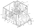
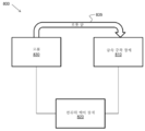
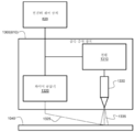
도 1은 금속 증착 장치를 포함하는 적층 제조 시스템의 일 실시예를 도시한다.
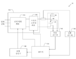
도 2는 소모성 와이어 전극에 동작가능하게 연결된 도 1의 적층 제조 시스템의 전원의 일 실시예의 개략적인 블록도를 도시한다.
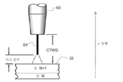
도 3은 적층 제조되는 3D 부품의 빌드 층과 용접 전극 간에 아크를 생성하는 일 실시예를 도시하는 도면이다.
도 4는 적층 제조되는 3D 부품의 빌드 층의 길이를 따라 증착되는 실질적으로 정현파의 비드형 직조 패턴의 일 실시예를 도시하는 도면이다.
도 5는 적층 제조되는 3D 부품의 빌드 층의 길이를 따라 증착되는 실질적으로 삼각형의 비드형 직조 패턴의 일 실시예를 도시하는 도면이다.
도 6은 적층 제조되는 3D 부품의 빌드 층의 길이를 따라 증착되는 실질적으로 직사각형의 비드형 직조 패턴의 일 실시예를 도시하는 도면이다.
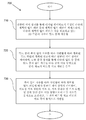
도 7은 적층 제조되는 3D 부품의 빌드 층을 충전하는 방법의 일 실시예의 흐름도를 도시한다.
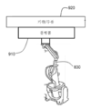
도 8은 금속 증착 장치, 컴퓨터 제어 장치, 및 로봇 암을 갖는 로봇을 구비하는 적층 제조 시스템의 일 실시예의 시스템 블록도를 도시한다.
도 9는, 로봇이 금속 증착 장치에 연결되는 대신 3D 부품 또는 기판을 유지하는 플랫폼에 동작가능하게 연결되는, 도 8의 적층 제조 시스템의 대체 실시예의 일부를 도시한다.
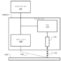
도 10은 소모성 전극 기반인 도 8의 금속 증착 장치의 일 실시예의 시스템 블록도를 도시한다.
도 11은 레이저 기반인 도 8의 금속 증착 장치의 일 실시예의 시스템 블록도를 도시한다.
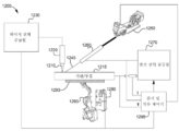
도 12는, 도 11과 유사한, 레이저 열선(laser hot wire; LHW) 시스템으로서 구성된 금속 증착 장치를 갖는 적층 제조 시스템의 일 실시예의 시스템 블록도를 도시한다.
도 13은 비소모성 전극 기반인 도 8의 금속 증착 장치의 일 실시예의 시스템 블록도를 도시한다.
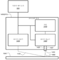
도 14는 소모성 전극 기반이면서 필러 와이어 기반인 도 8의 금속 증착 장치의 일 실시예의 시스템 블록도를 도시한다.
도 15는 도 1, 도 2, 도 8, 도 10, 도 11, 도 12, 도 13, 및 도 14의 시스템의 예시적인 컴퓨터 제어 장치 또는 제어기의 일 실시예를 도시한다.The accompanying drawings, which are incorporated in and form a part of this specification, illustrate various embodiments of the present disclosure. It will be understood that the element boundaries (eg, boxes, groups of boxes, or other shapes) illustrated in the drawings represent one embodiment of the boundary. In some embodiments, one element may be designed as multiple elements, or multiple elements may be designed as one element. In some embodiments, elements shown as internal components of other elements can be implemented as external components, and vice versa. Also, the elements may not be drawn at a uniform rate.
1 shows an embodiment of a additive manufacturing system that includes a metal deposition apparatus.
FIG. 2 shows a schematic block diagram of one embodiment of a power supply of the additive manufacturing system of FIG. 1 operably connected to a consumable wire electrode.
FIG. 3 is a diagram showing an embodiment of generating an arc between a build layer of a 3D component manufactured in a stack and a welding electrode.
FIG. 4 is a diagram showing one embodiment of a substantially sinusoidal bead-like weave pattern deposited along the length of a build layer of a 3D component being stacked.
FIG. 5 is a diagram showing one embodiment of a substantially triangular bead-like weave pattern deposited along the length of a build layer of a 3D component being fabricated.
FIG. 6 is a diagram showing one embodiment of a substantially rectangular bead-like weave pattern deposited along the length of a build layer of a 3D component being fabricated.
7 shows a flow diagram of one embodiment of a method of filling a build layer of a 3D component that is manufactured in additive manufacturing.
8 shows a system block diagram of one embodiment of a additive manufacturing system having a metal deposition apparatus, a computer control apparatus, and a robot with a robot arm.
FIG. 9 shows a portion of an alternative embodiment of the additive manufacturing system of FIG. 8 in which the robot is operatively connected to a platform for holding 3D parts or substrates instead of being connected to a metal deposition apparatus.
10 shows a system block diagram of one embodiment of the metal deposition apparatus of FIG. 8 that is based on a consumable electrode.
11 shows a system block diagram of one embodiment of the metal deposition apparatus of FIG. 8 that is laser based.
12 shows a system block diagram of one embodiment of a additive manufacturing system having a metal deposition apparatus configured as a laser hot wire (LHW) system, similar to FIG. 11.
FIG. 13 shows a system block diagram of one embodiment of the metal deposition apparatus of FIG. 8 that is based on non-consumable electrodes.
14 shows a system block diagram of one embodiment of the metal deposition apparatus of FIG. 8 that is consumable electrode based and filler wire based.
15 shows one embodiment of an exemplary computer control device or controller of the system of FIGS. 1, 2, 8, 10, 11, 12, 13, and 14;
일반적으로 알려진 바와 같이, 적층 제조는, 원하는 제조된 제품을 생성하기 위해 재료가 베이스/기판 또는 부품 상에 (예를 들어, 층으로) 증착되는 공정이다. 일 실시예에 따르면, 적층 제조될 3차원(3D) 부품의 다수의 층의 패턴들은 디지털 데이터로서 표현되고 저장된다. 디지털 데이터는, 예를 들어, CAD 모델 또는 스캐닝된 부품으로부터 온 것일 수 있다. 일부 응용분야에서, 제조 물품은 상당히 복잡할 수 있다. 그러나, 적층 제조에서 충전에 사용되는 공지된 방법 및 시스템은 느리고 성능이 제한되는 경향이 있다. 본 발명의 실시예들은, 충전 동안 동적 비드형 직조 패턴을 증착하는 시스템 및 방법을 제공함으로써 충전 문제를 해결한다.As is generally known, additive manufacturing is a process in which materials are deposited (eg, in layers) on a base/substrate or component to produce a desired manufactured product. According to one embodiment, patterns of multiple layers of a three-dimensional (3D) component to be fabricated are represented and stored as digital data. The digital data can be, for example, from CAD models or scanned parts. In some applications, articles of manufacture can be quite complex. However, the known methods and systems used for filling in additive manufacturing tend to be slow and limited in performance. Embodiments of the present invention solve the filling problem by providing a system and method for depositing a dynamic bead-like woven pattern during filling.
적층 제조 시스템 및 방법의 실시예들을 개시한다. 일 실시예에서, 적층 제조 시스템은, 디지털 데이터로서 저장되고 적층 제조될 3차원(3D) 부품의 다수의 빌드 층에 대응하는 다수의 계획된 빌드 패턴에 액세스하도록 구성된 컴퓨터 제어 장치를 포함한다. 이 시스템은 금속 증착 장치도 포함한다. 금속 증착 장치는, 빌드 층의 폭이 길이 치수를 따라 가변됨에 따라, 3D 부품의 다수의 빌드 층 중의 빌드 층의 길이 치수를 따라 금속 재료의 비드형 직조 패턴을 증착하도록 구성된다. 증착은, 다수의 계획된 빌드 패턴 중의 계획된 빌드 패턴의 계획된 경로에 따라 컴퓨터 제어 장치의 제어하에 있다. 길이 치수를 따라 폭이 가변됨에 따라, 비드형 직조 패턴의 증착 동안 비드형 직조 패턴의 직조 폭, 직조 주파수, 직조 드웰, 및 길이 치수를 따른 금속 증착 장치의 이동 속도가 동적으로 조절된다. 동적 조절은, 계획된 빌드 패턴에 따라 컴퓨터 제어 장치의 제어하에 있으며, 비드형 직조 패턴의 비드 폭을 동적으로 가변한다. 계획된 빌드 패턴과 이에 따른 계획된 경로 및 동적 조절은, 경로 계획 소프트웨어를 사용하여 경로 계획 개발의 일부로서 미리 생성된다.Embodiments of additive manufacturing systems and methods are disclosed. In one embodiment, the additive manufacturing system includes a computer control device configured to access multiple planned build patterns corresponding to multiple build layers of three-dimensional (3D) parts to be stored and digitally manufactured as digital data. The system also includes a metal deposition apparatus. The metal deposition apparatus is configured to deposit a beaded weave pattern of metallic material along the length dimension of the build layer among multiple build layers of the 3D part, as the width of the build layer varies along the length dimension. The deposition is under the control of a computer control device according to the planned path of the planned build pattern among a number of planned build patterns. As the width varies along the length dimension, the movement speed of the metal deposition apparatus along the weave width, weave frequency, weave dwell, and length dimension of the bead weave pattern during the deposition of the bead weave pattern is dynamically adjusted. The dynamic adjustment is under the control of the computer control device according to the planned build pattern, and the bead width of the bead-shaped weave pattern is dynamically varied. Planned build patterns and thus planned routes and dynamic adjustments are generated in advance as part of route planning development using route planning software.
금속 증착 장치의 실시예들은, 예를 들어, 금속 와이어를 용융하여 금속 재료를 종착하도록, 예를 들어, 레이저 기반 서브시스템, 플라즈마 기반 서브시스템, 아크 기반 서브시스템, 전자 빔 기반 서브시스템, 또는 전기 저항 기반 서브시스템 중 적어도 하나를 포함할 수 있다. 또한, 금속 증착 장치의 일부 실시예는, 예를 들어, 소모품 금속 와이어를 공급/전달하여 베이스 상에 3D 부품을 적층 제조하기 위한 와이어 전달 또는 공급 시스템을 포함할 수 있다. 또한, 금속 증착 장치의 일부 실시예는, 예를 들어, 레이저 빔, 플라즈마 빔, 전기 아크, 전자 빔, 또는 소모성 금속 와이어를 베이스 또는 기판 상에 적층 제조되고 있는 3D 부품에 대하여 이동시키도록 운동학적 제어 요소(예를 들어, 로봇 공학) 또는 다른 유형의 제어 요소(예를 들어, 광학 제어 요소)를 포함할 수 있다.Embodiments of the metal deposition apparatus may, for example, melt a metal wire to terminate a metal material, eg, a laser based subsystem, a plasma based subsystem, an arc based subsystem, an electron beam based subsystem, or electricity It may include at least one of the resistance-based subsystem. Further, some embodiments of the metal deposition apparatus may include, for example, a wire transfer or supply system for supplying/delivering consumable metal wires to manufacture and stack 3D parts on a base. In addition, some embodiments of the metal deposition apparatus are kinematic to move, for example, a laser beam, a plasma beam, an electric arc, an electron beam, or a consumable metal wire with respect to a 3D component being stacked on a base or substrate. Control elements (eg, robotics) or other types of control elements (eg, optical control elements).
본원의 예들과 도면은 단지 예시적인 것이며 청구범위의 범주 및 사상에 의해 측정되는 본 발명을 제한하려는 것이 아니다. 이제 본 발명의 예시적인 실시예들을 설명하기 위한 것이지 제한하려는 것이 아닌 도면을 참조해 보면, 도 1은 본 발명의 실시예들을 금속 증착 장치를 포함하는 적층 제조 시스템의 일 실시예를 예시하는 맥락에서 나타낸 것이다. 금속 증착 장치는, 전형적으로, 예를 들어, 가스 금속 아크 용접(GMAW), 플럭스-코어 아크 용접(FCAW), 또는 가스 텅스텐 아크 용접(GTAW)과 같은 용접 공정에 의해 층별로 부품을 적층 제조하는 것을 돕는 데 사용될 수 있음을 고려할 수 있다. 본원에서 나중에 설명하는 바와 같이, 다른 실시예들에 따르면, 다른 금속 증착 공정들도 가능하다.The examples and figures herein are illustrative only and are not intended to limit the invention as measured by the scope and spirit of the claims. Referring now to the drawings, which are intended to illustrate exemplary embodiments of the present invention and are not intended to be limiting, FIG. 1 illustrates the embodiments of the present invention in the context of illustrating one embodiment of a additive manufacturing system including a metal deposition apparatus. It is shown. The metal deposition apparatus typically stacks parts by layer by a welding process such as, for example, gas metal arc welding (GMAW), flux-core arc welding (FCAW), or gas tungsten arc welding (GTAW). It can be considered that it can be used to help. Other metal deposition processes are possible, according to other embodiments, as described later herein.
도 1을 참조하면, 적층 제조 시스템(10)은, 일반적으로 프레임(12), 프레임 내에 배치된 로봇(14), 및 프레임 내에 또한 각각 배치된 제1 및 제2 테이블(16, 18)을 포함한다. 적층 제조 시스템(10)은, 이하에 더욱 상세히 설명하는 방식으로 부품들(예를 들어, 22 및 24)을 적층 제조하는 데 유용하다. 도 1에 도시된 실시예에서, 프레임(12)은 로봇(14)과 테이블들(16 및 18)을 둘러싸기 위한 복수의 측벽과 도어를 포함한다. 평면도에서는 실질적으로 직사각형 구성이 도시되어 있지만, 프레임(12)과 시스템(10)은 많은 구성을 취할 수 있다.1, the
전방 액세스 도어(26)는 프레임의 내부에 액세스하도록 프레임(12)에 장착된다. 전방 액세스 도어(26)는, 도어가 2개의 힌지 세트인 도어(26)를 프레임(12)에 부착하는 제1 힌지 세트 및 도어의 한 패널을 다른 패널에 부착하는 제2 힌지 세트를 포함하는 이중 접힘 구성을 취할 수 있다. 그럼에도 불구하고, 전방 액세스 도어(26)는 슬라이딩 도어 또는 스윙 도어 등의 다른 구성을 취할 수 있다. 유사하게, 후방 액세스 도어(28)도 프레임(12)에 장착된다. 도시된 실시예에서는 후방 액세스 도어(28)도 이중 접힘 구성을 취하고 있으나, 후방 액세스 도어는 전방 액세스 도어(26)와 관련하여 전술한 바와 같이 다른 구성을 취할 수 있다. 윈도우(32)는 어느 도어에나 제공될 수 있다(전방 도어(26)에만 도시되어 있다). 윈도우는 당업계에 공지된 착색 안전 스크린을 포함할 수 있다.The
제어 패널(40)은 전방 도어(26)에 인접한 프레임(12) 상에 제공된다. 제어 패널(40) 상에 제공된 제어 노브 및/또는 스위치는 프레임(12)에 역시 장착된 제어 인클로저(42) 내에 수용된 제어부와 통신한다. 제어 패널(40) 상의 제어부는, 공지된 적층 제조 시스템과 함께 사용되는 제어부와 유사한 방식으로 적층 제조 시스템(10)에서 수행되는 동작을 제어하는 데 사용될 수 있다.The
일 실시예에서, 로봇(14)은 지지부 상에 장착되는 받침대 상에 장착된다. 도시된 실시예의 로봇(14)은 테이블들(16 및 18)에 대해 중심에 있으며 다수의 이동 축을 포함한다. 필요한 경우, 받침대는 터렛과 유사하게 지지부에 대해 회전할 수 있다. 이에 따라, 어떤 종류의 구동 메커니즘, 예를 들어, 모터 및 변속기(도시하지 않음)는, 로봇(14)을 회전시키기 위한 지지부 및/또는 받침대에 수용될 수 있다.In one embodiment, the
일 실시예에서, 증착 도구(60)는 금속 증착 장치의 일부이며 로봇(14)의 암의 원위 단부에 부착된다. 증착 도구(60)는, 예를 들어, 본원에서 나중에 설명하는 실시예들에 따르면, 접촉 팁을 갖는 용접 건 또는 토치, 레이저 장치, 또는 비소모성 전극 장치를 포함할 수 있다. 증착 도구(60)는 금속 재료의 증착을 가능하게 한다. 일 실시예에서, 가요성 튜브 또는 도관(62)은 증착 도구(60)에 부착된다. 용기(66) 내에 저장될 수 있는 소모성 금속 와이어(64)(예를 들어, 와이어 전극 또는 필러 와이어로서 사용됨)는 도관(62)을 통해 증착 도구(60)로 전달된다. 일 실시예에서, 와이어 공급기(68)는, 금속 증착 장치의 일부이며, 소모품 금속 와이어(64)를 증착 도구(60)로 전달하는 것을 용이하게 하도록 프레임(12)에 부착된다.In one embodiment, the
로봇(14)은 프레임(12)의 베이스 또는 하측 부분에 장착된 것으로 도시되어 있지만, 필요한 경우, 로봇(14)은 프레임의 상측 구조에 장착될 수 있고 시스템(10)에 하향으로 의존할 수 있다. 일 실시예에서, 전력 공급원(72)(전원)은, 적층 제조 동작을 지원하기 위한 금속 증착 장치의 일부이며, 프레임(12)에 연결되고 프레임의 일부일 수 있는 플랫폼(74)에 장착되어 플랫폼 상에 안착된다. 다른 일 실시예에서, 전력 공급원(72)은, 2개의 개별 전력 공급원(예를 들어, 하나는 증착 도구(60)에서 레이저에 전력을 공급하기 위한 것이고 나머지 하나는 소모성 금속 와이어가 증착 도구(60)를 통과할 때 소모성 금속 와이어(64)를 가열하기 위한 것임)으로서 구현될 수 있다. 컴퓨터 제어 장치(76)는, 후술하는 바와 같이 적층 제조 시스템(10)(로봇(14)을 포함)의 다양한 부품과 통신하고 이러한 부품을 제어하며, 플랫폼(74) 상에 안착 및 장착된다.The
도 2는, 소모성 와이어 전극(64)에 동작가능하게 연결된 도 1의 적층 제조 시스템(10)의 전원(72)의 예시적인 실시예의 개략적 블록도를 도시한다. 전원(72)은, 와이어(64)와 워크피스 부품(22) 간에 아크를 형성함으로써 증착 동안 와이어(64)를 용융하도록 와이어(64)와 워크피스 부품(22) 간에 용접 출력 전력을 제공하는 브리지 스위칭 회로(180)와 전력 변환 회로(110)를 갖는 스위칭 전력 공급원(105)을 포함한다. 전력 변환 회로(110)는 하프 브리지 출력 토폴로지에 기초하는 변압기일 수 있다. 예를 들어, 전력 변환 회로(110)는, 예를 들어, 용접 변압기의 일차측 및 이차측에 의해 각각 기술되는 바와 같은 입력 전력측 및 출력 전력측을 포함하는 인버터 유형일 수 있다. 예를 들어, DC 출력 토폴로지를 갖는 초퍼 유형 등의 다른 유형의 전력 변환 회로도 가능하다. 전원(72)은, 또한, 전력 변환 회로(110)에 동작가능하게 연결되고 (예를 들어, AC 동작을 위해) 용접 출력 전류의 극성의 방향을 스위칭하도록 구성된 브리지 스위칭 회로(180)를 포함한다.FIG. 2 shows a schematic block diagram of an exemplary embodiment of the
전원(72)은 파형 생성기(120) 및 제어기(130)를 더 포함한다. 파형 생성기(120)는 제어기(130)의 명령에 따라 용접 파형을 생성할 수 있다. 파형 생성기(120)에 의해 생성된 파형은, 전력 변환 회로(110)의 출력을 변조하여 와이어(64)와 워크피스 부품(22) 간의 출력 전류를 생성한다. 제어기(130)는, 또한, 브리지 스위칭 회로(180)의 스위칭을 명령하고, 전력 변환 회로(110)에 전력을 공급하는 제어 명령을 제공할 수 있다.The
일 실시예에서, 전원(72)은, 와이어(64)와 워크피스 부품(22) 간의 출력 전압과 전류를 감시하고 감시된 전압과 전류를 제어기(130)에 다시 제공하도록 전압 피드백 회로(140) 및 전류 피드백 회로(150)를 더 포함한다. 피드백 전압과 전류는, 예를 들어, 파형 생성기(120)에 의해 생성되는 용접 파형을 수정하는 것과 관련하여 결정을 내리고 및/또는 예컨대 전원(72)의 동작에 영향을 미치는 다른 결정을 내리도록 제어기(130)에 의해 사용될 수 있다.In one embodiment,
일 실시예에 따르면, 스위칭 전원(105), 파형 생성기(120), 제어기(130), 전압 피드백 회로(140), 및 전류 피드백 회로(150)는 전원(72)을 구성한다. 적층 제조 시스템(10)은, 또한, 일 실시예에 따라 소모품 금속 와이어(64)를 증착 도구(60)를 통해 워크피스 부품(22)을 향하여 선택된 와이어 공급 속도(WFS)로 공급하는 와이어 공급기(68)를 포함한다. 와이어 공급기(68), 소모성 금속 와이어(64), 및 워크피스 부품(22)은, 전원(72)의 일부는 아니지만, 예를 들어, 하나 이상의 출력 케이블을 통해 전원(72)에 동작가능하게 연결될 수 있다.According to one embodiment, the switching
도 3은 (증착 도구(60)로부터 나오는) 소모품 금속 와이어(64)와 적층 제조되고 있는 3D 부품(22) 사이에 아크를 생성하는 일 실시예를 도시하는 도면이다. 도 3에 도시된 바와 같이, 부품(22)의 빌드 층(N)과 빌드 층(N+l)은 아크를 통해 소모성 금속 와이어(64)를 용융함으로써 증착되었다. 아크 길이 및 접촉 팁 대 워크 거리(CTWD)도 도 3에 도시되어 있다. 일 실시예에 따르면, 실질적으로 일정한 CTWD는, 본원에서 나중에 설명하는 바와 같이 증착 동안 제어되고 유지된다. 전문이 본원에 참고로 원용되는 미국 특허번호 제9,815,135호는 CTWD의 개념 및 CTWD를 결정하고 제어하는 방법을 개시하고 있다.FIG. 3 is a diagram showing one embodiment of creating an arc between the consumable metal wire 64 (from the deposition tool 60) and the
다른 일 실시예에 따르면, 증착 도구(60)는 레이저 장치를 포함하고, 전원(72)은, 레이저 빔을 형성하여 증착 동안 소모성 금속 와이어(64)(예를 들어, 필러 와이어)를 용융하게끔 레이저 장치에 전력(에너지)을 제공하도록 구성된다. 또 다른 일 실시예에 따르면, 증착 도구(60)는 비소모성 전극(예를 들어, 텅스텐 전극)을 포함하고, 전원(72)은, 비소모성 전극과 부품 간에 아크를 형성함으로써 증착 동안 소모성 금속 와이어(64)(예를 들어, 필러 와이어)를 용융하게끔 전력(에너지)을 제공하도록 구성된다. 일부 실시예에서, 소모성 금속 와이어(64)는 증착 도구(60)를 통해 공급되며, 증착 도구(60)는, 예를 들어, 접촉 팁, 레이저 장치, 또는 비소모성 전극을 포함한다. 다른 실시예에서, 소모성 금속 와이어(64)는 접촉 팁, 레이저 장치, 또는 비소모성 전극을 갖는 증착 도구(60)를 통해 공급되지 않을 수 있다. 대신, 소모성 금속 와이어(64)는, 적어도 도 11 내지 도 13에 대하여 본 원에서 나중에 설명하는 바와 같이, 증착 도구(60)의 인접한 위치로부터 이러한 증착 도구의 출력을 향하여 공급될 수 있다.According to another embodiment, the
도 4는 적층 제조되는 3D 부품의 예시적인 빌드 층의 길이를 따라 증착되는 실질적으로 정현파의 비드형 직조 패턴(400)의 일 실시예를 도시하는 도면이다. 도 4에서, 빌드 층은 위에서 보는 것으로 되어 있다. 도 4는 빌드 층의 2개의 미리 증착된 윤곽 또는 경계(410 및 420)를 도시한다. 빌드 층의 (폭 치수(425)에서의) 폭은 빌드 층의 길이 치수(430)를 따라 가변된다. 즉, 도 4의 상단으로부터 도 4의 하단으로 길이 치수(430)의 방향을 따라, 빌드 층은, 좁게 시작하고, 점진적으로 넓어지고, 최대 폭을 잠시 동안 유지한 다음, 점진적으로 좁아진다. 길이 치수에 대한 폭의 다른 변형을 갖는 다른 빌드 층도 가능하다.FIG. 4 is a diagram illustrating one embodiment of a substantially sinusoidal bead-
윤곽들(410 및 420) 사이의 빌드 층은 (예를 들어, 도 4의 상단에서 시작하여 도 4의 하단에서 끝나는) 비드형 직조 패턴(400)으로서 금속 재료로 충전된다. 예를 들어, 도 1을 참조하면. 컴퓨터 제어 장치(76)는, 증착 도구(60)를 계획된 경로를 따라 이동시켜 증착된 비드형 직조 패턴(400)이 윤곽들(410, 420) 사이의 빌드 층에서 충전되게끔 로봇(14)을 제어하도록 구성된다. 도 4를 참조하면, 증착 동안, 빌드 층의 폭이 길이 치수(430)를 따라 가변됨에 따라, 비드형 직조 패턴(400)의 직조 폭(440)과 직조 주파수가 가변된다. 또한, 증착 동안 길이 치수(430)를 따라 빌드 층의 폭이 가변됨에 따라, 비드형 직조 패턴(400)의 직조 드웰이 가변된다. 또한, 증착 도구(60)의 (예를 들어, 도 4의 상단으로부터 도 4의 하단으로 향하는 증착 이동 방향(450)으로의) 이동 속도는, 증착 동안 빌드 층의 폭이 길이 치수를 따라 가변됨에 따라, 가변된다. 직조 폭, 직조 주파수, 직조 드웰, 및 이동 속도는, 빌드 층의 계획된 빌드 패턴에 따라 증착 동안 컴퓨터 제어 장치(76)에 의해 제어된다.The build layer between the
도 4와 유사하게, 도 5는 적층 제조되는 3D 부품의 빌드 층의 길이를 따라 증착되는 실질적으로 삼각형의 비드형 직조 패턴(500)의 일 실시예를 도시하는 도면이다. 도 4 및 도 5와 유사하게, 도 6은 적층 제조되는 3D 부품의 빌드 층의 길이를 따라 증착되는 실질적으로 직사각형의 비드형 직조 패턴(600)의 일 실시예를 도시하는 도면이다. 다른 실시예들에 따르면, 다양한 직조 폭과 직조 주파수를 갖는 다른 비드형 직조 패턴도 가능하다.Similar to FIG. 4, FIG. 5 is a diagram illustrating one embodiment of a substantially triangular bead-
비드는 빌드 층의 폭을 가로지르는 금속 증착 패스이고, 비드형 직조 패턴은 단순히 비드형 직조 패턴을 위한 빌드 층의 계획된 경로를 따른 위치에 있는 일련의 금속 증착 패스이다. 비드형 직조 패턴의 증착된 금속 비드들(패스들)은, 다양한 파라미터(직조 폭, 직조 주파수, 직조 드웰, 및 이동 속도)가 동적으로 조절되는 방식에 따라, 실질적으로 유사하거나 실질적으로 다른 크기(비드 폭, 예를 들어, 도 4의 비드 폭(460) 참조)를 가질 수 있고 서로 유사하거나 상이하게 이격될 수 있다(예를 들어, 도 4의 비드 간격(470) 참조). 일 실시예에 따르면, 비드 폭(460)의 범위는 빌드 층의 길이에 걸쳐 4 mm 내지 12 mm일 수 있다. 직조 폭(440)은 사실상 증착의 임의의 부분을 따른 직조 패턴의 피크 대 피크 진폭이다(예를 들어, 도 4 참조). 직조 주파수는 단위 시간당(또는 이동 방향(450)을 따른 단위 길이당) 직조 사이클의 수이며 직조 파장의 역수이다. 증착 도구가 실제로 비드형 직조 패턴을 위한 계획된 경로(예를 들어, 정현파 경로, 삼각형 경로, 또는 직사각형 경로)를 따라 이동하더라도, 빌드 층의 길이 치수(430)를 따른 이동 방향(450)의 이동 속도는, 기본적으로 증착 동안 임의의 시점에서 길이 치수(430)를 따른 유효 순간 선형 이동 속도이다. 직조 드웰은 직조 패턴의 어느 한쪽 단부에서의 일시정지 시간이다. 예를 들어, (도 4 내지 도 6에서와 같이) 좌측/우측으로 직조를 행할 때, 직조 드웰은 좌측 이동의 끝에서 그리고 다시 우측 이동의 끝에서의 일시정지 시간이다. 예를 들어, 직조 주파수가 1 Hz이고 직조 드웰이 0.2초인 경우, 중간을 가로지르는 이동은, 차이며, 즉, 1초 - 0.2초(좌측) - 0.2초(우측) = 총 0.6초, 이어서, 2개의 이동 움직임(한 사이클에 걸쳐 좌측 이동과 우측 이동)으로 나누어져, 좌측 이동 비드당 0.3초의 이동 시간과 우측 이동 비드당 0.3초의 이동 시간이 발생한다. 직조 드웰 동안, 공정은 비드형 직조 패턴의 가장자리에 열을 가한다. 비드가 다른 비드 옆에 배치될 때, 직조 드웰은, 공극을 남게 하는 브리징 없이 금속이 이전 층과 이전 비드의 모서리로 흐를 수 있도록 설정된다.The beads are metal deposition passes across the width of the build layer, and the beaded weave pattern is simply a series of metal deposition passes in position along the planned path of the build layer for the beaded weave pattern. The deposited metal beads (passes) of the bead-like weave pattern are substantially similar or substantially different in size, depending on how various parameters (weave width, weave frequency, weave dwell, and travel speed) are dynamically adjusted. It may have a bead width, eg,
도 7은 적층 제조되는 3D 부품의 빌드 층을 충전하는 방법(700)의 일 실시예의 흐름도를 도시한다. 방법(700)의 블록(710)에서는, 컴퓨터 제어 장치(예를 들어, 도 1의 컴퓨터 제어 장치(76))를 통해 계획된 빌드 패턴에 액세스한다. 계획된 빌드 패턴은, (예를 들어, 컴퓨터 제어 장치(76)의 저장 서브시스템에(예컨대 도 15 참조)) 디지털 데이터로서 저장된 다수의 계획된 빌드 패턴 중 하나이다. 다수의 계획된 빌드 패턴은 적층 제조되는 3차원(3D) 부품(예를 들어, 도 1의 3D 부품(22))의 다수의 빌드 층에 대응한다.7 shows a flow diagram of one embodiment of a
블록(720)에서는, 금속 재료의 비드형 직조 패턴(예를 들어, 도 4의 비드형 직조 패턴(400))을, 다수의 빌드 층 중의 빌드 층의 길이 치수를 따라 증착 이동 방향(450)으로 증착한다. 증착은, 빌드 층의 폭이 길이 치수를 따라 가변됨에 따라, 계획된 빌드 패턴의 계획된 경로에 따라 컴퓨터 제어 장치(예를 들어, 도 1의 컴퓨터 제어 장치(76))의 제어하에 금속 증착 장치(예를 들어, 도 1의 전력 공급원(72), 와이어 공급기(68), 및 증착 도구(60))를 통해 달성된다.In
블록(730)에서는, 비드형 직조 패턴의 직조 폭, 직조 주파수, 및 직조 드웰을, 증착 동안 증착 이동 방향(450)으로의 이동 속도와 함께 동적으로 조절한다. 동적 조절은, 폭이 길이 치수를 따라 가변됨에 따라, 계획된 빌드 패턴에 따라 컴퓨터 제어 장치(예를 들어, 도 1의 컴퓨터 제어 장치(76))의 제어하에 수행된다. 그 결과, 비드형 직조 패턴(예를 들어, 도 4의 비드형 직조 패턴(400))의 비드 폭이 동적으로 가변된다. 일 실시예에 따르면, 계획된 빌드 패턴이 경로 계획 개발 동안 미리 결정되어 있으므로, 수행될 동적 조절이 미리 결정된다. 즉, 내부충전 공정 동안 직조 폭, 직조 주파수, 직조 드웰, 및 이동 속도의 조절은 즉석에서 결정되지 않는다.In
일 실시예에 따르면, 방법(700)에서의 증착 동안 직조 폭, 직조 주파수, 직조 드웰, 및 이동 속도를 동적으로 조절하여 빌드 층의 적절한 내부충전을 제공한다. 동적 조절은, 비드 폭을 넓히거나 좁게 하여 적절한 내부충전을 제공하고 금속 재료의 실질적으로 일정한 증착률을 유지할 수 있게 한다. 일반적으로, 충전 영역이 넓어질수록, 이동 속도가 느려지고, 직조 폭이 개방되며, 비드가 넓어진다(반대의 경우도 마찬가지이다). 일 실시예에 따르면, 증착 동안 빌드 층의 폭이 빌드 층의 길이를 따라 넓어지면, 이동 속도가 감소되고, 직조 폭이 증가되고, 직조 주파수가 감소되고(즉, 직조 파장이 증가되고), 직조 드웰이 증가된다. 일 실시예에 따르면, 증착 동안 빌드 층의 폭이 빌드 층의 길이를 따라 좁아지면, 이동 속도가 증가되고, 직조 폭이 감소되고, 직조 주파수가 증가되고(즉, 직조 파장이 감소되고), 직조 드웰이 감소된다. 또한, 일 실시예에 따르면, 직조 파라미터와 이동 속도의 동적 증가 및 감소는, 경로 계획 개발의 일부로서 미리 결정되고 실시간으로 동적으로 결정되지 않는다. 그러나, 실시간 동적 조절이 즉석에서 수행되는 다른 실시예들이 있을 수 있다.According to one embodiment, the woven width, weave frequency, weave dwell, and travel speed during deposition in
또한, 일 실시예에 따르면, 컴퓨터 제어 장치의 제어하에 비드형 직조 패턴의 증착 동안 실질적으로 일정한 접촉 팁 대 워크 거리(CTWD)가 유지된다. 예를 들어, 본원에 참고로 원용되는 미국 공개특허출원번호 제2017/0252847 A1호는 CTWD를 제어하는 방식을 개시한다. 내부충전 증착 동안 이동 속도 및 직조 파라미터가 동적으로 변화하여 CTWD에 영향을 줄 수 있지만, 미국 공개특허출원번호 제2017/0252847 A1호에 개시된 CTWD 제어 공정은, CTWD를 실질적으로 일정하게 유지하고 이에 따라 동적 증착 내부충전 공정으로 인한 CTWD 변화를 보상하는 데 사용될 수 있다. 또한, 일 실시예에서는, 컴퓨터 제어 장치의 제어하에 비드형 직조 패턴의 증착 동안 실질적으로 일정한 와이어 공급 속도(WFS)가 유지된다. 다른 일 실시예에서는, WFS도 동적으로 가변될 수 있다.Further, according to one embodiment, a substantially constant contact tip-to-work distance (CTWD) is maintained during deposition of a bead-like woven pattern under the control of a computer controlled device. For example, US Published Patent Application No. 2017/0252847 A1, incorporated herein by reference, discloses a method of controlling CTWD. The CTWD control process disclosed in U.S. Patent Application Publication No. 2017/0252847 A1 maintains the CTWD substantially constant and accordingly, although the movement speed and weaving parameters during dynamic charge deposition may dynamically change to affect the CTWD. It can be used to compensate for CTWD changes due to the dynamic deposition internal filling process. Further, in one embodiment, a substantially constant wire feed rate (WFS) is maintained during deposition of the bead-like weave pattern under the control of a computer controlled device. In another embodiment, WFS can also be dynamically varied.
일부 실시예에서, 모든 파라미터(이동 속도 및 직조 파라미터)가 비드형 직조 패턴의 증착 동안 동시에 변경될 필요는 없다. 예를 들어, 빌드 층의 내부충전 영역의 형상에 따라, 모든 파라미터(이동 속도, 직조 폭, 직조 주파수, 직조 드웰)가 변경될 수 있고, 또는 이들 중 일부(예를 들어, 직조 폭과 직조 드웰)만이 변경될 수 있다. 파라미터들이 서로에 대해 동적으로 어떻게 변하는지의 관계는 빌드 층에 대한 경로 계획 개발 중에 미리 결정되며, 이에 따라 빌드 층의 효율적이고 효과적인 내부충전 증착을 초래한다.In some embodiments, not all parameters (movement speed and weaving parameters) need to be changed simultaneously during deposition of a beaded weave pattern. For example, depending on the shape of the inner filling area of the build layer, all parameters (movement speed, weave width, weave frequency, weave dwell) can be changed, or some of them (eg weave width and weave dwell) ) Can only be changed. The relationship of how the parameters change dynamically with respect to each other is predetermined during the development of the route plan for the build layer, thus resulting in efficient and effective internal fill deposition of the build layer.
일 실시예에 따르면, 경로 계획 개발 동안, 빌드 층의 폭이 변함에 따라, 경로 계획 소프트웨어는, 현재 비드 패스를 가로질러 충전될 필요가 있는 영역을 결정하고, 해당 영역의 적절한 내부충전을 위해 파라미터들(이동 속도 및 직조 파라미터)을 동적으로 조절한다. 경로 계획 소프트웨어의 G-코드의 슬라이싱 소프트웨어가 영역 결정에 관련된다. 경로 계획 소프트웨어는, 적층 제조될 3D 부품의 CAD 모델 또는 3D 부품의 스캐닝으로부터 도출된 디지털 데이터에 기초하여 빌드 층 상의 현재 비드 패스의 위치를 "알고 있다".According to one embodiment, during the development of the route plan, as the width of the build layer changes, the route plan software determines the area that needs to be charged across the current bead pass, and parameters for proper internal filling of the area. The fields (moving speed and weaving parameters) are dynamically adjusted. The slicing software of the G-code of the route planning software is involved in area determination. The route planning software "knows" the location of the current bead pass on the build layer based on the CAD model of the 3D part to be additively manufactured or the digital data derived from scanning the 3D part.
도 8은 금속 증착 장치(810), 컴퓨터 제어 장치(820), 및 로봇 암(835)을 갖는 로봇(830)을 구비하는 적층 제조 시스템(800)의 일 실시예의 시스템 블록도를 도시한다. 금속 증착 장치(810)는 적층 제조 공정 동안 용융된 금속 재료를 증착하여 부품을 형성하도록 구성된다. 컴퓨터 제어 장치(820)는 금속 증착 장치(810) 및 로봇(830)에 동작가능하게 결합된다. 즉, 도 8의 실시예에서, 컴퓨터 제어 장치(820)는, 금속 증착 장치(810)의 다양한 양태(예를 들어, 와이어 공급, 출력 전력 또는 에너지)를 제어하고 로봇(830)을 위한 움직임 제어기로서 기능하도록 구성된다. 다른 실시예들에 따르면, 컴퓨터 제어 장치(820)는, 2개 이상의 제어기(예를 들어, 금속 증착 장치(810)를 제어하기 위한 제1 제어기 및 로봇(830)을 제어하기 위한 제2 제어기)를 포함할 수 있다. 일 실시예에서, 로봇 암(835)은, 로봇(830)이 컴퓨터 제어 장치(820)의 제어하에 베이스 또는 기판에 대하여 암(835)을 통해 공간에서 금속 증착 장치(810)를 이동시킬 수 있도록 금속 증착 장치(810)(또는 증착 도구 등의 금속 증착 장치(810)의 적어도 일부)에 결합된다. 다른 일 실시예에서, 로봇 암(835)은, 로봇(830)이 금속 증착 장치(810)에 대해 암(835)을 통해 공간에서 베이스 또는 기판을 이동시킬 수 있도록 베이스 또는 기판에 결합된다.8 shows a system block diagram of one embodiment of a
일 실시예에 따르면, 컴퓨터 제어 장치(820)는, 적층 제조 공정의 윤곽 증착 단계 동안 베이스(기판) 상에 용융된 금속 재료를 증착하여 부품의 윤곽을 형성하도록 금속 증착 장치(810)에 명령한다. 이어서, 컴퓨터 제어 장치(820)는, 적층 제조 공정의 내부충전 패턴 증착 단계 동안 베이스 상에 금속 재료를 증착하여 부품의 윤곽에 의해 윤곽이 잡힌 영역 내에 비드형 직조패턴을 형성하도록 금속 증착 장치(810)에 명령한다. 일 실시예에 따르면, 윤곽 증착 단계의 증착률은 내부충전 패턴 증착 단계의 증착률보다 낮으며, 이는 윤곽이 내부충전 패턴보다 정확하고 정밀하게 증착될 수 있게 한다. 적층 제조 공정이 부품의 연속적 빌드 층들을 형성함에 따라, 금속 재료가, 예를 들어, 내부충전 패턴 및 윤곽의 이전 층 상에 증착된다.According to one embodiment, the
도 9는 도 8의 적층 제조 시스템(800)의 대체 실시예의 일부를 도시하며, 여기서, 로봇(830)은 금속 증착 장치(810)에 연결되는 대신 3D 부품 또는 기판(920)을 유지하는 플랫폼(910)에 동작가능하게 연결된다. 금속 증착 장치(810)와 로봇(830)은, 예를 들어, 소정의 실시예에 따르면, 도 1과 도 9에 도시한 유형일 수 있다. 다른 다양한 실시예에 따르면, 다른 유형의 로봇 및 금속 증착 장치도 가능하다. 예를 들어, 도 10 내지 도 14는 본원에서 후술하는 금속 증착 장치의 다양한 실시예를 도시한다.9 shows a portion of an alternative embodiment of the
도 10은, 도 8의 컴퓨터 제어 장치(820)에 의해 제어되는 전원(1010)과 와이어 공급기(1020)를 포함하고 소모성 전극 기반인 도 8의 금속 증착 장치(810)의 일 실시예(1000)의 시스템 블록도를 도시한다. 금속 증착 장치(1000)는, 또한, 증착 도구(1025)(예를 들어, 접촉 팁(1027)을 갖는 용접 토치 또는 건)을 포함한다. 금속 증착 장치(1000)는, 예를 들어, 소정의 실시예에 따르면, 도 1 및 도 2와 유사한 요소들 및/또는 요소들의 조합들을 가질 수 있다. 와이어 공급기(1020)는, 금속 재료의 소모성 와이어 전극(1030)을 증착 도구(1025)를 통해 베이스 또는 부품(1040)을 향하여 공급하도록 구성된다. 전원(1010)과 증착 도구(1025)는 와이어 공급기(1020)에 동작가능하게 연결된다. 전원(1010)과 와이어 공급기(1020)는, 에너지를 (전극(1030)과 베이스/부품(1040) 간에 전기 아크(1035)를 형성하는) 소모성 와이어 전극(1030)을 통해 제공하여 적층 제조 공정 동안 소모성 와이어 전극(1030)(및 가능하게는 베이스(1040)의 일부)을 용융하도록 구성된다. 소모품 와이어 전극(1030)에 대한 전기적 접촉은 증착 도구(1025)의 접촉 팁(1027)을 통해 이루어진다. 도 8의 로봇(830)은, 본원에서 설명하는 바와 같이 컴퓨터 제어 장치(820)의 제어하에 금속 증착 장치(1000)(또는 단지 증착 도구(1025)) 또는 베이스/부품(1040)을 이동시켜 비드형 직조 패턴을 증착시킬 수 있다. 다시, 적층 제조 공정이 부품의 연속적 빌드 층들을 계속 형성함에 따라, 금속 재료가, 예를 들어, 유사한 방식으로 이전 빌드 층 상에 증착된다.FIG. 10 is an
도 11은, 도 8의 컴퓨터 제어 장치(820)에 의해 제어되는, 레이저 기반이고 전원(1110), 와이어 공급기(1120), 및 레이저 장치(1130)를 포함하는 도 8의 금속 증착 장치(810)의 일 실시예(1100)의 시스템 블록도를 도시한다. 금속 증착 장치(1100)는 적층 제조 공정 동안 금속 필러 와이어를 증착하도록 구성된다. 일 실시예에서는, 레이저 장치(1130)와 와이어 공급기(1120)가 증착 도구를 구성할 수 있다. 다른 일 실시예에서는, 레이저 장치(1130)가 증착 도구를 구성할 수 있다. 금속 증착 장치(1100)는, 예를 들어, 소정의 실시예에 따르면, 도 1 및 도 2와 유사한 요소들 및/또는 요소들의 조합들을 가질 수 있다. 와이어 공급기(1120)는 금속 재료의 필러 와이어(1140)를 베이스 또는 부픔(1040)을 향해 공급하도록 구성된다. 도 11의 금속 증착 장치(1100)의 실시예는, 또한, 전원(1110) 및 전원(1110)에 동작가능하게 연결된 레이저 장치(1130)를 포함한다. 전원(1110) 및 레이저 장치(1130)는, 적층 제조 공정 동안 (레이저 빔(1135)의 형태인) 에너지를 제공하여 필러 와이어(1140)(및 가능하게는 베이스 또는 부품(1040)의 일부)를 용융하도록 구성된다. 도 8의 로봇(830)은, 금속 증착 장치(1100)(또는 단지 레이저 장치(1130)) 또는 베이스/부품(1040)을 이동시켜 본원에서 설명하는 바와 같이 컴퓨터 제어 장치(820)의 제어하에 비드형 직조 패턴을 증착시킬 수 있다. 다시, 적층 제조 프로세스가 부품의 연속적 빌드 층들을 계속 형성함에 따라, 금속 재료는, 예를 들어, 유사한 방식으로 이전 빌드 층 상에 증착된다.FIG. 11 is a metal-based
도 11과 유사하게, 일 실시예에 따르면, 금속 증착 장치를 갖는 적층 제조 시스템은 도 12에서와 같이 레이저 열선(LHW) 시스템(1200)으로서 구성될 수 있다. 도 12의 시스템(1200)은 필러 와이어 공급기와 및 에너지원의 조합의 예시적인 일 실시예를 포함한다. 특히, 시스템(1200)은, 레이저 빔(1210)을 베이스/기판 또는 부분(1215)에 포커싱하여 베이스/기판 또는 부품(1215)을 가열할 수 있는 레이저 서브시스템을 포함한다. 일 실시예에서, 레이저 서브시스템은 고강도 에너지원이다. 레이저 서브시스템은, 이산화탄소, Nd:YAG, Yb-디스크, YB-섬유, 섬유 전달형 또는 직접 다이오드 레이저 시스템을 포함하지만 이에 제한되지 않는 임의의 유형의 고 에너지 레이저원일 수 있다. 다른 일 실시예에서, 레이저 서브시스템은 (예를 들어, 금속 재료를 연화시키거나 최소한으로 용융하기 위한) 저강도 에너지원이다.Similar to FIG. 11, according to one embodiment, a additive manufacturing system having a metal deposition apparatus may be configured as a laser heating (LHW)
이하에서는 레이저 시스템, 빔, 및 전력 공급원을 반복해서 언급할 것이다. 그러나, 임의의 에너지원을 사용할 수 있으므로, 이러한 참조는 예시적인 것으로 이해해야 한다. 예를 들어, 고강도 에너지원은 적어도 500 W/cm2를 제공할 수 있다. 레이저 서브시스템은 서로 동작가능하게 연결된 레이저 장치(1220)와 레이저 전력 공급원(1230)을 포함한다. 레이저 전력 공급원(1230)은 레이저 장치(1220)를 동작시키기 위한 전력을 제공한다.In the following, laser systems, beams, and power sources will be referred to repeatedly. However, since any energy source can be used, it should be understood that this reference is illustrative. For example, a high intensity energy source can provide at least 500 W/cm 2 . The laser subsystem includes a
일 실시예에서, 시스템(1200)은, 또한, 적어도 하나의 저항성 필러 와이어(1240)를 제공하여 레이저 빔(1210) 근처에서 베이스/기판 또는 부품(1215)과 접촉시킬 수 있는 핫 필러 와이어 공급기 서브시스템을 포함한다. 와이어 공급기 서브시스템은 필러 와이어 공급기(1250), 접촉 튜브(1260), 및 전력 공급원(1270)을 포함한다. 동작 동안, 필러 와이어(1240)는, 접촉 튜브(1260)와 베이스/기판 또는 부품(1215) 사이에 동작가능하게 연결된 전력 공급원(1270)으로부터의 전류에 의해 저항성 가열된다. 일 실시예에 따르면, 전력 공급원(1270)은 펄스형 직류(DC) 전력 공급원이지만, 교류(AC) 또는 다른 유형의 전력 공급원도 가능하다. 와이어(1240)는, 필러 와이어 공급기(1250)로부터 접촉 튜브(1260)를 통해 베이스/기판 또는 부품(1215)을 향해 공급되고 튜브(1260)를 넘어 연장된다. 와이어(1240)의 연장 부분은, 베이스/기판 또는 부품(1215)과 접촉하기 전에 그 연장 부분이 용융점에 접근하거나 도달하도록 저항성 가열된다. 레이저 빔(1210)은, 베이스/기판 또는 부품(1215)의 베이스 금속의 일부를 용융하여 퍼들(puddle)을 형성하도록 기능할 수 있고, 및/또는 와이어(1240)를 베이스/기판 또는 부품(1215) 상으로 용융하도록 또한 사용될 수 있다. 전력 공급원(1270)은 필러 와이어(1240)를 저항성 용융하는 데 필요한 에너지를 제공한다. 일부 실시예에서는, 전력 공급원(1270)이 필요한 모든 에너지를 제공하는 반면, 다른 실시예에서는 레이저 또는 다른 에너지 열원이 일부 에너지를 제공할 수 있다.In one embodiment,
시스템(1200)은, 레이저 빔(1210)과 저항성 필러 와이어(1240)가 서로 고정된 관계로 유지되도록 (적어도 상대적인 의미로) 베이스/기판 또는 부품(1215)을 따라 동일하게 제어되는 방향(예를 들어, 비드형 직조 패턴)으로 레이저 빔(1210)(에너지원) 및/또는 저항성 필러 와이어(1240)를 이동시킬 수 있는 움직임 제어 서브시스템을 더 포함한다. 예를 들어, 일 실시예에서, 저항성 필터 와이어(1240)는 레이저 장치(1220)와 접촉 튜브(1260)를 수용하는 증착 도구를 통해 공급될 수 있다. 다양한 실시예에 따르면, 베이스/기판 또는 부품(1215)과 레이저/와이어 조합 간의 상대적 움직임은, 베이스/기판 또는 부품(1215)을 실제로 이동시킴으로써, 또는 예를 들어 레이저 장치(1220)와 와이어 공급기 서브시스템의 적어도 일부(예컨대, 접촉 튜브(1260))를 갖는 증착 도구를 이동시킴으로써 달성될 수 있다. 예를 들어, 레이저 장치(1220)와 접촉 튜브(1260)는 단일 증착 도구 내에 통합될 수 있다. 증착 도구는, 증착 도구에 동작가능하게 연결된 움직임 제어 서브시스템을 통해 베이스/기판 또는 부품(1215)을 따라 이동할 수 있다.The
도 12에서, 움직임 제어 서브시스템은, 플랫폼(1293)(예를 들어, 회전가능한 플랫폼 및/또는 병진이동가능한 플랫폼)을 갖는 로봇(1290)에 동작가능하게 연결된 컴퓨터 제어 장치(1280)를 포함한다. 컴퓨터 제어 장치(1280)는 로봇(1290)의 움직임을 제어한다. 로봇(1290)은, 예를 들어, 레이저 빔(1210)과 와이어(1240)가 베이스/기판 또는 부품(1215)을 따라 효과적으로 이동하게끔 베이스/기판 또는 부품(1215)을 비드형 직조 패턴으로 이동시키도록 플랫폼(1293)을 통해 베이스/기판 또는 부품(1215)에 동작가능하게 연결(예를 들어, 기계적으로 고정)된다. 플랫폼(1293)을 구동하는 로봇(1290)은 다양한 실시예에 따라 전기식, 공압식, 또는 유압식으로 구동될 수 있다. 일 실시예에 따르면, 컴퓨터 제어 장치(1280)와 로봇(1290)을 포함하는 움직임 제어 서브시스템은, 적층 제조 시스템의 개별 부품이며, 금속 증착 장치의 일부가 아니다.In FIG. 12, the motion control subsystem includes a
적층 제조 시스템(1200)은, 베이스/기판 또는 부품(1215) 및 접촉 튜브(1260)에 동작가능하게 연결되고(즉, 전력 공급원(1270)의 출력에 효과적으로 연결되고) 베이스/기판 또는 부품(1215)과 와이어(1240) 간의 전위차(즉, 전압 V) 및 베이스/기판 또는 부품과 와이어를 통한 전류를 측정할 수 있는 감지 및 전류 제어 서브시스템(1295)을 더 포함한다. 감지 및 전류 제어 서브시스템(1295)은, 또한, 측정된 전압 및 전류로부터 저항값(R = V/I) 및/또는 전력값(P = V*I)을 계산할 수 있다. 일반적으로, 와이어(1240)가 베이스/기판 또는 부품(1215)과 접촉할 때, 와이어(1240)와 베이스/기판 또는 부품(1215) 간의 전위차는 0볼트(또는 거의 0볼트)이다. 결과적으로, 감지 및 전류 제어 서브시스템(1295)은, 저항성 필러 와이어(1240)가 베이스/기판 또는 부품(1215)과 접촉할 때를 감지할 수 있고, 감지에 응답하여 저항성 필러 와이어(1240)를 통한 전류의 흐름을 또한 제어할 수 있도록 전력 공급원(1270)에 동작가능하게 연결된다. 다른 일 실시예에 따르면, 감지 및 전류 제어기(1295)는 전력 공급원(1270)의 필수 부품일 수 있다.The
도 13은, 도 8의 컴퓨터 제어 장치(820)에 의해 적어도 부분적으로 제어되는, 전원(1310), 와이어 공급기(1320), 및 비소모성 전극(1330)(예를 들어, 텅스텐 전극)을 포함하며 비소모성 전극 기반인 도 8의 금속 증착 장치(810)의 일 실시예(1300)의 시스템 블록도를 도시한다. 금속 증착 장치(1300)는 적층 제조 공정 동안 금속 필러 와이어를 증착하도록 구성된다. 금속 증착 장치(1300)는, 예를 들어, 일부 실시예에 따르면 도 1 및 도 2와 유사한 요소들 및/또는 요소들의 조합들을 가질 수 있다. 와이어 공급기(1320)는 금속 재료의 필러 와이어(1325)를 베이스(1040)를 향해 공급하도록 구성된다. 비소모성 전극(1330)은 전원(1310)에 동작가능하게 연결된다. 전원(1310)과 비소모성 전극(1330)은, 적층 제조 공정 동안 (플라즈마 빔 또는 아크(1335)의 형태인) 에너지를 제공하여 필러 와이어(1325)(및 가능하게는 베이스 또는 부품(1040)의 일부)를 용융하여 예를 들어 비드형 직조 패턴을 증착하도록 구성된다. 컴퓨터 제어 장치(820)는 와이어 공급기(1320) 및 전원(1310)에 동작가능하게 연결되어 이들의 적어도 일부를 제공한다. 다시, 적층 제조 공정이 부품의 연속적 빌드 층들을 계속 형성함에 따라, 금속 재료는, 예를 들어, 유사한 방식으로 이전 빌드 층 상에 증착된다.FIG. 13 includes a
도 14는, 도 8의 컴퓨터 제어 장치(820)에 의해 적어도 부분적으로 제어되는, 전원(1410), 제1 와이어 공급기(1420), 및 제2 와이어 공급기(1430)를 포함하며 소모성 전극 기반 및 필러 와이어 기반인 도 8의 금속 증착 장치(810)의 일 실시예(1400)의 시스템 블록도를 도시한다. 금속 증착 장치(1400)는, 또한, 증착 도구(1425)(예를 들어, 접촉 팁(1415)을 갖는 용접 토치 또는 건)를 포함한다. 금속 증착 장치(1400)는, 예를 들어, 소정의 실시예에 따라 도 1 및 도 2와 유사한 요소들 및/또는 요소들의 조합들을 가질 수 있다. 제2 와이어 공급기(1430)는 금속 재료의 필러 와이어(1435)를 베이스 또는 부품(1040)을 향해 공급하도록 구성된다. 제1 와이어 공급기(1420)는, 전원(1410)에 동작가능하게 연결되고, 소모성 와이어 전극(1450)을 베이스 또는 부품(1040)을 향해 공급하도록 구성된다. 전원(1410)과 제1 와이어 공급기(1420)는, 적층 제조 공정 동안 에너지를 (전극(1450)과 베이스 또는 부품(1040) 사이에 전기 아크를 형성하는) 소모성 와이어 전극(1450)을 통해 제공하여 필러 와이어(1435) 및 소모성 와이어 전극(1450)(및 가능하게는 베이스 또는 부품(1040)의 일부)을 용융하도록 구성된다. 컴퓨터 제어 장치(820)는, 제1 와이어 공급기(1420), 제2 와이어 공급기(1430), 및 전원(1410)에 동작가능하게 연결되어 이들을 적어도 부분적으로 제어한다. 다시, 적층 제조 공정이 부품의 연속적 빌드 층들을 계속 형성함에 따라, 금속 재료는, 예를 들어, 유사한 방식으로 이전 빌드 층 상에 증착된다.FIG. 14 includes a power supply 1410, a first wire feeder 1420, and a
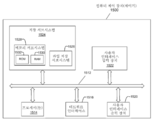
도 15는 도 1, 도 2, 도 8, 도 10, 도 11, 도 12, 도 13, 및 도 14의 시스템의 예시적인 컴퓨터 제어 장치(또는 제어기)(1500)의 일 실시예를 도시한다. 컴퓨터 제어 장치(또는 제어기)(1500)는 버스 서브시스템(1512)을 통해 다수의 주변 장치와 통신하는 적어도 하나의 프로세서(1514)를 포함한다. 이들 주변 장치는, 예를 들어, 메모리 서브시스템(1528)과 파일 저장 서브시스템(1526)을 포함하는 저장 서브시스템(1524), 사용자 인터페이스 입력 장치(1522), 사용자 인터페이스 출력 장치(1520), 및 네트워크 인터페이스 서브시스템(1516)을 포함할 수 있다. 입력 및 출력 장치들은 컴퓨터 제어 장치(또는 제어기)(1500)와의 사용자 상호작용을 허용한다. 네트워크 인터페이스 서브시스템(1516)은, 외부 네트워크에 대한 인터페이스를 제공하고, 다른 컴퓨터 시스템의 대응하는 인터페이스 장치에 결합된다. 예를 들어, 시스템(10)의 컴퓨터 제어 장치(76)는, 컴퓨터 제어 장치(또는 제어기)(1500)와 하나 이상의 특성을 공유할 수 있고, 예를 들어, 종래의 컴퓨터, 디지털 신호 프로세서, 및/또는 다른 연산 장치일 수 있다.15 shows an embodiment of an exemplary computer control device (or controller) 1500 of the system of FIGS. 1, 2, 8, 10, 11, 12, 13, and 14. Computer control device (or controller) 1500 includes at least one
사용자 인터페이스 입력 장치(1522)는, 키보드, 마우스, 트랙볼, 터치패드, 또는 그래픽 태블릿과 같은 포인팅 장치, 스캐너, 디스플레이에 통합된 터치스크린, 음성 인식 시스템, 마이크, 및/또는 다른 유형의 입력 장치와 같은 오디오 입력 장치를 포함할 수 있다. 일반적으로, "입력 장치"라는 용어의 사용은, 정보를 컴퓨터 제어 장치(또는 제어기)(1500) 또는 통신 네트워크에 입력하기 위한 모든 가능한 유형의 장치 및 방법을 포함하고자 하는 것이다.The user
사용자 인터페이스 출력 장치(1520)는 디스플레이 서브시스템, 프린터, 팩스기, 또는 오디오 출력 장치와 같은 비시각적 디스플레이를 포함할 수 있다. 디스플레이 서브시스템은 음극선관(CRT), 액정 디스플레이(LCD)와 같은 평판 장치, 투영 장치, 또는 가시 화상을 생성하기 위한 다른 메커니즘을 포함할 수 있다. 디스플레이 서브시스템은, 또한, 오디오 출력 장치를 통한 것과 같은 비시각적 디스플레이를 제공할 수 있다. 일반적으로, "출력 장치"라는 용어의 사용은, 컴퓨터 제어 장치(또는 제어기)(1500)로부터 사용자 또는 다른 기계 또는 컴퓨터 시스템으로 정보를 출력하기 위한 모든 가능한 유형의 장치 및 방법을 포함하고자 하는 것이다.The user
저장 서브시스템(1524)은 (예를 들어, 소프트웨어 모듈로서) 본원에 설명한 기능 중 일부 또는 전부를 제공하거나 지원하는 프로그래밍 및 데이터 컨스트럭트(construct)를 저장한다. 예를 들어, 저장 서브시스템(1524)은 적층 제조될 3D 부품의 CAD 모델 및 3D 부품의 다수의 빌드 층에 대응하는 다수의 계획된 빌드 패턴을 포함할 수 있다.The
소프트웨어 모듈은 일반적으로 프로세서(1514)에 의해 단독으로 또는 다른 프로세서와의 조합으로 실행된다. 저장 서브시스템에서 사용되는 메모리(1528)는, 프로그램 실행 동안 명령 및 데이터를 저장하기 위한 메인 랜덤 액세스 메모리(RAM)(1530) 및 고정 명령이 저장되는 리드 온리 메모리(ROM)(1532)를 포함하는 다수의 메모리를 포함할 수 있다. 파일 저장 서브시스템(1526)은, 프로그램 및 데이터 파일을 위한 영구 저장을 제공할 수 있으며, 하드 디스크 드라이브, 연관된 탈착식 매체를 갖는 플로피 디스크 드라이브, CD-ROM 드라이브, 광학 드라이브, 또는 탈착식 매체 카트리지를 포함할 수 있다. 소정의 실시예의 기능을 구현하는 모듈은, 파일 서브시스템(1526)에 의해 저장 서브시스템(1524)에 또는 프로세서(들)(1514)에 의해 액세스가능한 다른 기계에 저장될 수 있다.The software modules are generally executed by the
버스 서브시스템(1512)은, 컴퓨터 제어 장치(또는 제어기)(1500)의 다양한 구성요소 및 서브시스템이 의도된 대로 서로 통신하게 하는 메커니즘을 제공한다. 버스 서브시스템(1512)은 단일 버스로서 개략적으로 도시되어 있지만, 버스 서브시스템의 대체 실시예는 다수의 버스를 사용할 수 있다.The
컴퓨터 제어 장치(또는 제어기)(1500)는, 워크스테이션, 서버, 연산 클러스터, 블레이드 서버, 서버 팜, 또는 다른 임의의 데이터 처리 시스템 또는 연산 장치를 포함하는 다양한 유형일 수 있다. 연산 장치 및 네트워크의 끊임없이 변화하는 특성으로 인해, 도 15에 도시된 컴퓨터 제어 장치(또는 제어기)(1500)의 설명은 일부 실시예를 예시하기 위한 특정 예로서만 의도된 것이다. 도 15에 도시된 컴퓨터 제어 장치(또는 제어기)보다 많거나 적은 구성요소를 갖는 컴퓨터 제어 장치(또는 제어기)(1500)의 다른 많은 구성이 가능하다.Computer control device (or controller) 1500 may be of various types, including workstations, servers, compute clusters, blade servers, server farms, or any other data processing system or computing device. Due to the ever-changing nature of computing devices and networks, the description of the computer control device (or controller) 1500 shown in FIG. 15 is intended as a specific example only to illustrate some embodiments. Many other configurations of the computer control device (or controller) 1500 with more or fewer components than the computer control device (or controller) shown in FIG. 15 are possible.
개시된 실시예들을 상당히 상세하게 예시하고 설명하였지만, 첨부된 청구범위의 범위를 이러한 세부사항으로 한정하거나 어떤 식으로든 제한하려는 것은 아니다. 물론, 주제의 다양한 양태를 설명하기 위해 구성요소 또는 방법의 모든 가능한 조합을 설명할 수는 없다. 그러므로, 본 개시 내용은, 도시되고 설명된 특정 세부사항 또는 예시적인 예들로 제한되지 않는다. 따라서, 본 개시 내용은, 미국 특허법(35 U.S.C.ξ101)의 법적 주제 요건을 충족시키는 첨부된 청구범위의 범주 내에 속하는 변경, 수정, 및 변형을 포함하고자 하는 것이다. 특정 실시예들의 상기 설명은 예로서 주어진 것이다. 주어진 개시 내용으로부터, 통상의 기술자는, 일반적인 발명의 개념 및 수반되는 이점을 이해할 뿐만 아니라, 개시된 구조와 방법에 대한 명백하고 다양한 변경과 수정도 알게 될 것이다. 그러므로, 이러한 모든 변경과 수정을 첨부된 청구범위 및 그 균등물에 의해 정의되는 바와 같이 일반적인 발명 개념의 사상 및 범위 내에 속하는 것으로서 포함하고자 한다.Although the disclosed embodiments have been illustrated and described in considerable detail, they are not intended to limit the scope of the appended claims to these details or in any way. Of course, not all possible combinations of elements or methods can be described to describe various aspects of the subject matter. Therefore, the present disclosure is not limited to the specific details or illustrative examples shown and described. Accordingly, this disclosure is intended to cover changes, modifications, and variations that fall within the scope of the appended claims that meet the legal subject requirements of the United States Patent Law (35 U.S.C.ξ101). The above description of specific embodiments is given as an example. From the given disclosure, one of ordinary skill in the art will not only understand the general concept of the invention and its accompanying advantages, but will also recognize obvious and various changes and modifications to the disclosed structures and methods. Therefore, all such changes and modifications are intended to be included as falling within the spirit and scope of the general inventive concept as defined by the appended claims and equivalents thereof.
Claims (22)
적층 제조될 3차원(3D) 부품의 다수의 빌드(build) 층에 대응하는, 디지털 데이터로서 저장된 다수의 계획된 빌드 패턴에 액세스하도록 구성된 컴퓨터 제어 장치; 및
금속 재료를 증착하여 상기 3D 부품의 상기 다수의 빌드 층 중의 빌드 층의 적어도 일부를 형성하도록 구성된 금속 증착 장치를 포함하고,
상기 금속 재료는, 상기 컴퓨터 제어 장치의 제어하에, 상기 다수의 계획된 빌드 패턴 중의 계획된 빌드 패턴의 계획된 경로에 따라 비드형 직조 패턴(beaded weave pattern)으로서 증착되고, 상기 계획된 빌드 패턴이 상기 빌드 층에 대응하고,
상기 비드형 직조 패턴의 직조 폭, 직조 주파수, 및 직조 드웰(dwell)은, 상기 빌드 층의 폭이 상기 빌드 층의 길이 치수를 따라 가변됨에 따라, 상기 계획된 빌드 패턴에 따라 상기 컴퓨터 제어 장치의 제어하에 상기 비드형 직조 패턴의 증착 동안 동적으로 조절되고, 이에 따라 상기 비드형 직조 패턴의 비드 폭이 동적으로 가변되는, 적층 제조 시스템.As an additive manufacturing system,
A computer control device configured to access a number of planned build patterns stored as digital data, corresponding to a number of build layers of three-dimensional (3D) parts to be stacked; And
A metal deposition apparatus configured to deposit a metal material to form at least a portion of a build layer of the plurality of build layers of the 3D part,
The metallic material is deposited as a beaded weave pattern along a planned path of a planned build pattern among the plurality of planned build patterns, under the control of the computer control device, and the planned build pattern is applied to the build layer. To respond,
The weave width, weave frequency, and weave dwell of the beaded weave pattern are controlled by the computer control device according to the planned build pattern as the width of the build layer varies along the length dimension of the build layer. The additive manufacturing system, under which the bead-like weave pattern is dynamically adjusted during deposition, and thus the bead width of the bead-like weave pattern is dynamically varied.
접촉 팁을 갖는 증착 도구;
상기 증착 도구에 동작가능하게 연결되고, 상기 금속 재료의 소모성 와이어 전극을 상기 증착 도구를 통해 상기 3D 부품을 향하여 공급하도록 구성된 와이어 공급기; 및
상기 와이어 공급기에 동작가능하게 연결된 전원을 포함하고,
상기 전원은, 에너지를 제공하여 상기 소모성 와이어 전극과 상기 3D 부품 간에 아크를 형성함으로써 상기 비드형 직조 패턴의 증착 동안 적어도 상기 소모성 와이어 전극을 용융하도록 구성된, 적층 제조 시스템.According to claim 1, The metal deposition apparatus,
A deposition tool having a contact tip;
A wire feeder operably connected to the deposition tool and configured to supply a consumable wire electrode of the metallic material through the deposition tool toward the 3D component; And
And a power source operably connected to the wire supply,
And the power source is configured to provide energy to form an arc between the consumable wire electrode and the 3D component to melt at least the consumable wire electrode during deposition of the beaded woven pattern.
상기 금속 재료의 필러 와이어를 상기 3D 부품을 향하여 공급하도록 구성된 와이어 공급기;
전원; 및
상기 전원에 동작가능하게 연결된 레이저를 포함하고,
상기 전원과 상기 레이저는, 레이저 빔의 형태인 에너지를 제공하여 상기 비드형 직조 패턴의 증착 동안 적어도 상기 필러 와이어를 용융하도록 구성된, 적층 제조 시스템.According to claim 1, The metal deposition apparatus,
A wire feeder configured to supply the filler wire of the metallic material toward the 3D part;
power; And
And a laser operably connected to the power source,
The power supply and the laser are configured to provide energy in the form of a laser beam to melt at least the filler wire during deposition of the beaded weave pattern.
상기 금속 재료의 필러 와이어를 상기 3D 부품을 향하여 공급하도록 구성된 와이어 공급기;
전원; 및
상기 전원에 동작가능하게 연결된 비소모성 전극(non-consumable electrode)을 포함하고,
상기 전원과 상기 비소모성 전극은, 에너지를 제공하여 상기 비소모성 전극과 상기 3D 부품 간에 아크를 형성함으로써 상기 비드형 직조 패턴의 증착 동안 적어도 상기 필러 와이어를 용융하도록 구성된, 적층 제조 시스템.According to claim 1, The metal deposition apparatus,
A wire feeder configured to supply the filler wire of the metallic material toward the 3D part;
power; And
And a non-consumable electrode operably connected to the power source,
The power source and the non-consumable electrode are configured to melt energy to at least melt the filler wire during deposition of the bead-like woven pattern by providing energy to form an arc between the non-consumable electrode and the 3D component.
상기 금속 재료의 필러 와이어를 상기 3D 부품을 향하여 공급하도록 구성된 제1 와이어 공급기;
전원; 및
상기 전원에 동작가능하게 연결되고, 상기 금속 재료의 소모성 와이어 전극을 상기 3D 부품을 향하여 공급하도록 구성된 제2 와이어 공급기를 포함하고,
상기 전원은, 에너지를 제공하여 상기 소모성 와이어 전극과 상기 3D 부품 간에 아크를 형성함으로써 상기 비드형 직조 패턴의 증착 동안 적어도 상기 소모성 와이어 전극과 상기 필러 와이어를 용융하도록 구성된, 적층 제조 시스템.According to claim 1, The metal deposition apparatus,
A first wire feeder configured to supply the filler wire of the metallic material toward the 3D component;
power; And
A second wire feeder operatively connected to the power source and configured to supply a consumable wire electrode of the metallic material towards the 3D component,
And the power source is configured to provide energy to form an arc between the consumable wire electrode and the 3D component to melt at least the consumable wire electrode and the filler wire during deposition of the bead-like weave pattern.
컴퓨터 제어 장치를 통해 디지털 데이터로서 저장된 다수의 계획된 빌드 패턴 중의 계획된 빌드 패턴에 액세스하는 단계로서, 상기 다수의 계획된 빌드 패턴은 적층 제조되고 있는 3차원(3D) 부품의 다수의 빌드 층에 대응하는, 단계;
상기 빌드 층의 폭이 상기 다수의 빌드 층 중의 상기 빌드 층의 길이 치수를 따라 가변됨에 따라, 상기 계획된 빌드 패턴의 계획된 경로에 따라 상기 컴퓨터 제어 장치의 제어하에 금속 증착 장치를 통해 상기 길이 치수를 따른 증착 이동 방향으로 금속 재료의 비드형 직조 패턴을 증착하는 단계; 및
상기 폭이 상기 길이 치수를 따라 가변됨에 따라, 상기 계획된 빌드 패턴에 따라 상기 컴퓨터 제어 장치의 제어하에 상기 비드형 직조 패턴의 직조 폭, 직조 주파수, 및 직조 드웰을 동적으로 조절하고, 이에 따라 상기 비드형 직조 패턴의 비드 폭을 동적으로 가변하는 단계를 포함하는, 방법.As a method of filling the build layer of the additive manufacturing parts,
Accessing a planned build pattern among a plurality of planned build patterns stored as digital data through a computer control device, the plurality of planned build patterns corresponding to multiple build layers of a three-dimensional (3D) part being manufactured additively, step;
As the width of the build layer varies along the length dimension of the build layer of the plurality of build layers, along the length dimension of the computerized device under the control of the computer controlled device according to the planned path of the planned build pattern Depositing a bead-like weave pattern of a metal material in a deposition movement direction; And
As the width varies along the length dimension, the weave width, weave frequency, and weave dwell of the beaded weave pattern are dynamically adjusted under the control of the computer control device according to the planned build pattern, and the bead is dynamically adjusted accordingly. And dynamically varying the bead width of the mold woven pattern.
상기 폭이 상기 길이 치수를 따라 가변됨에 따라, 상기 계획된 빌드 패턴에 따라 상기 컴퓨터 제어 장치의 제어하에 상기 증착 동안 상기 증착 이동 방향의 이동 속도를 동적으로 조절하는 단계를 더 포함하는, 방법.The method of claim 12,
And as the width varies along the length dimension, dynamically adjusting the movement speed of the deposition movement direction during the deposition under the control of the computer control device according to the planned build pattern.
상기 와이어 공급기에 동작가능하게 연결된 상기 금속 증착 장치의 전원을 통해 에너지를 제공하여 상기 소모성 와이어 전극과 상기 3D 부품 간에 아크를 형성함으로써 상기 비드형 직조 패턴의 증착 동안 적어도 상기 소모성 와이어 전극을 용융하는 단계를 더 포함하는, 방법.The method of claim 12, further comprising: supplying a consumable wire electrode of the metal material toward the 3D component through a wire feeder of the metal deposition apparatus; And
Melting at least the consumable wire electrode during deposition of the bead-like weave pattern by forming an arc between the consumable wire electrode and the 3D component by providing energy through a power source of the metal deposition apparatus operably connected to the wire feeder. The method further comprising.
상기 금속 증착 장치의 레이저에 동작가능하게 연결된 상기 금속 증착 장치의 전원을 통해 에너지를 제공하여 상기 레이저와 상기 3D 부품 간에 레이저 빔을 형성함으로써 상기 비드형 직조 패턴의 증착 동안 적어도 상기 필러 와이어를 용융하는 단계를 더 포함하는, 방법.The method of claim 12, further comprising: supplying a filler wire of the metallic material toward the 3D component through a wire feeder of the metal deposition apparatus; And
Melting at least the filler wire during deposition of the bead-like weave pattern by providing energy through a power source of the metal deposition apparatus operatively connected to the laser of the metal deposition apparatus to form a laser beam between the laser and the 3D component. The method further comprising a step.
상기 금속 증착 장치의 비소모성 전극에 동작가능하게 연결된 상기 금속 증착 장치의 전원을 통해 에너지를 제공하여 상기 비소모성 전극과 상기 3D 부품 간에 아크를 형성함으로써 상기 비드형 직조 패턴의 증착 동안 적어도 상기 필러 와이어를 용융하는 단계를 더 포함하는, 방법.The method of claim 12, further comprising: supplying a filler wire of the metallic material toward the 3D component through a wire feeder of the metal deposition apparatus; And
At least the filler wire during deposition of the bead-like weave pattern by providing energy through a power source of the metal deposition apparatus operatively connected to the non-consumable electrode of the metal deposition apparatus to form an arc between the non-consumable electrode and the 3D component. The method further comprising the step of melting.
상기 금속 증착 장치의 제2 와이어 공급기를 통해 상기 금속 재료의 소모성 와이어 전극을 상기 3D 부품을 향하여 공급하는 단계; 및
상기 제2 와이어 공급기에 동작가능하게 연결된 상기 금속 증착 장치의 전원을 통해 에너지를 제공하여 상기 소모성 와이어 전극과 상기 3D 부품 간에 아크를 형성함으로써 상기 비드형 직조 패턴의 증착 동안 적어도 상기 소모성 와이어 전극과 상기 필러 와이어를 용융하는 단계를 더 포함하는, 방법.The method of claim 12, further comprising: supplying a filler wire of the metallic material toward the 3D component through a first wire feeder of the metal deposition apparatus;
Supplying a consumable wire electrode of the metal material toward the 3D component through a second wire feeder of the metal deposition apparatus; And
At least the consumable wire electrode and the during the deposition of the bead-shaped weave pattern by providing energy through a power source of the metal deposition apparatus operatively connected to the second wire supply to form an arc between the consumable wire electrode and the 3D component. The method further comprising melting the filler wire.
Applications Claiming Priority (2)
| Application Number | Priority Date | Filing Date | Title |
|---|---|---|---|
| US16/239,602 | 2019-01-04 | ||
| US16/239,602 US11305366B2 (en) | 2019-01-04 | 2019-01-04 | Systems and methods providing dynamic bead spacing and weave fill in additive manufacturing |
Publications (1)
| Publication Number | Publication Date |
|---|---|
| KR20200085650A true KR20200085650A (en) | 2020-07-15 |
Family
ID=69104260
Family Applications (1)
| Application Number | Title | Priority Date | Filing Date |
|---|---|---|---|
| KR1020190176444A KR20200085650A (en) | 2019-01-04 | 2019-12-27 | Systmes and methods providing dynamic bead spacing and weave fill in additive manufacturing |
Country Status (5)
| Country | Link |
|---|---|
| US (2) | US11305366B2 (en) |
| EP (1) | EP3689529B1 (en) |
| JP (1) | JP2020108905A (en) |
| KR (1) | KR20200085650A (en) |
| CN (1) | CN111408816A (en) |
Families Citing this family (6)
| Publication number | Priority date | Publication date | Assignee | Title |
|---|---|---|---|---|
| DE102017211982B4 (en) * | 2017-07-13 | 2019-04-18 | Trumpf Laser- Und Systemtechnik Gmbh | Method and device for joining at least two workpieces |
| US11826861B1 (en) * | 2020-08-12 | 2023-11-28 | Sion Power Corporation | Joining systems, clamping fixtures, and related systems and methods |
| US11759875B2 (en) * | 2020-09-23 | 2023-09-19 | International Business Machines Corporation | Autonomous robotic thread for repairing structures |
| EP4251403A2 (en) * | 2020-11-25 | 2023-10-04 | Chromatic 3D Materials Inc. | Height adjustment in a method of three dimensional printing |
| FR3135219A1 (en) * | 2022-05-03 | 2023-11-10 | Naval Group | Process for manufacturing a part by additive manufacturing by wire deposition |
| JP7345679B1 (en) | 2022-06-21 | 2023-09-15 | 三菱電機株式会社 | Additive manufacturing equipment and additive manufacturing method |
Family Cites Families (28)
| Publication number | Priority date | Publication date | Assignee | Title |
|---|---|---|---|---|
| JPS58192681A (en) | 1982-05-01 | 1983-11-10 | Mitsubishi Heavy Ind Ltd | Automatic controlling method of oscillation width |
| JPS60250877A (en) | 1984-05-28 | 1985-12-11 | Nippon Kokan Kk <Nkk> | Automatic controlling method of height of welding bead |
| GB2180183B (en) | 1985-07-31 | 1989-09-06 | Mitsubishi Electric Corp | Automatic welding machine correcting for a variable groove width |
| US4782206A (en) * | 1987-01-27 | 1988-11-01 | The Babcock & Wilcox Company | Method and apparatus for controlling weld bead shape to eliminate microfissure defects when shape melting austenitic materials |
| JP2586091B2 (en) | 1988-03-28 | 1997-02-26 | 日本鋼管株式会社 | Swing rotary arc welding method |
| US6909066B2 (en) | 2003-07-30 | 2005-06-21 | Edison Welding Institute | Adaptive and synergic fill welding method and apparatus |
| KR20030096151A (en) | 2003-11-21 | 2003-12-24 | 대한민국(부경대학교 총장) | Weldind machine control by bead image and Method of making bead image database and Welding method by bead image |
| SE0401542D0 (en) * | 2004-06-14 | 2004-06-14 | Abb Ab | A method and a device for providing feedback on weaving parameters |
| US20080053978A1 (en) * | 2006-08-29 | 2008-03-06 | Lincoln Global, Inc. | Welder with positional heat control and method of using same |
| JP2010131639A (en) * | 2008-12-05 | 2010-06-17 | Mitsubishi Heavy Ind Ltd | Clad welding method |
| US20120160819A1 (en) | 2010-12-23 | 2012-06-28 | Lincoln Global, Inc. | Wire feed speed measurement device |
| US20140008354A1 (en) | 2012-07-06 | 2014-01-09 | Lincoln Global, Inc. | Method and system of using induction heating to heat consumable during hot wire process |
| US9511442B2 (en) | 2012-07-27 | 2016-12-06 | Illinois Tool Works Inc. | Adaptable rotating arc welding method and system |
| KR101473639B1 (en) | 2013-02-25 | 2014-12-17 | 대우조선해양 주식회사 | Large volume butt joint welding apparatus and the method thereof |
| US9193002B2 (en) * | 2013-06-04 | 2015-11-24 | Caterpillar Inc. | Welding system implementing concurrent auto-dam fabrication |
| US9815135B2 (en) | 2013-10-22 | 2017-11-14 | Lincoln Global, Inc. | Systems and methods providing location feedback for additive manufacturing |
| US10682717B2 (en) | 2013-10-22 | 2020-06-16 | Lincoln Global, Inc. | Systems and methods providing location feedback for additive manufacturing |
| ES2815048T3 (en) * | 2013-11-13 | 2021-03-29 | Abb Schweiz Ag | Robotic 3D printing system |
| CN103726049B (en) * | 2014-01-09 | 2016-05-25 | 武汉新瑞达激光工程有限责任公司 | A kind of laser gain material manufacture method and equipment of metal parts |
| US10464168B2 (en) * | 2014-01-24 | 2019-11-05 | Lincoln Global, Inc. | Method and system for additive manufacturing using high energy source and hot-wire |
| DE102015202347A1 (en) * | 2015-02-10 | 2016-08-11 | Trumpf Laser- Und Systemtechnik Gmbh | Irradiation device, processing machine and method for producing a layer of a three-dimensional component |
| KR101750783B1 (en) | 2015-12-08 | 2017-06-27 | 한국생산기술연구원 | Control method for weaving motion in welding device and welding device using the same method |
| KR101923682B1 (en) | 2016-04-29 | 2018-11-30 | 슈퍼티그웰딩 주식회사 | Device for Controlling Automatic Welding with Automatic Voltage Control |
| CN106735730A (en) * | 2016-12-21 | 2017-05-31 | 北京航空航天大学 | Electric arc silk filling increasing material manufacturing method and device |
| BR102018005422A2 (en) * | 2017-03-21 | 2019-02-05 | Lincoln Global, Inc. | welding system |
| CN107414259B (en) * | 2017-09-20 | 2019-08-23 | 哈尔滨工业大学 | Auxiliary silk filling GMA increasing material manufacturing device and method for functionally gradient material (FGM) manufacture |
| CN108723549A (en) * | 2018-05-28 | 2018-11-02 | 河海大学常州校区 | A kind of electric arc increasing material manufacturing method |
| US10857667B2 (en) * | 2019-04-09 | 2020-12-08 | Arevo, Inc. | Methods and apparatus for controlling motion of an articulated robot |
-
2019
- 2019-01-04 US US16/239,602 patent/US11305366B2/en active Active
- 2019-12-27 JP JP2019238671A patent/JP2020108905A/en active Pending
- 2019-12-27 KR KR1020190176444A patent/KR20200085650A/en unknown
- 2019-12-31 CN CN201911408555.9A patent/CN111408816A/en active Pending
-
2020
- 2020-01-02 EP EP20150005.5A patent/EP3689529B1/en active Active
-
2022
- 2022-02-24 US US17/679,218 patent/US11731208B2/en active Active
Also Published As
| Publication number | Publication date |
|---|---|
| EP3689529B1 (en) | 2023-06-07 |
| CN111408816A (en) | 2020-07-14 |
| JP2020108905A (en) | 2020-07-16 |
| US11305366B2 (en) | 2022-04-19 |
| EP3689529A1 (en) | 2020-08-05 |
| EP3689529C0 (en) | 2023-06-07 |
| US11731208B2 (en) | 2023-08-22 |
| US20200215635A1 (en) | 2020-07-09 |
| US20220176483A1 (en) | 2022-06-09 |
Similar Documents
| Publication | Publication Date | Title |
|---|---|---|
| KR20200085650A (en) | Systmes and methods providing dynamic bead spacing and weave fill in additive manufacturing | |
| JP7186512B2 (en) | Method and system for hybrid deposition rate near-net-shape additive manufacturing | |
| JP7269717B2 (en) | System and method for supporting predictive and preventive maintenance | |
| JP3208808U (en) | A system that provides position feedback for additive manufacturing | |
| KR102452174B1 (en) | Systems and methods providing location feedback for additive manufacturing | |
| US10682717B2 (en) | Systems and methods providing location feedback for additive manufacturing | |
| JP2019111582A (en) | Systems and methods of additive structural build techniques | |
| US11858064B2 (en) | Path planning systems and methods for additive manufacturing | |
| US11027362B2 (en) | Systems and methods providing location feedback for additive manufacturing | |
| JP2019089108A (en) | Manufacturing method and manufacturing apparatus for molded object | |
| US20190366466A1 (en) | Systems and methods for additive manufacturing in a controlled short circuit welding system | |
| JP2020108905A5 (en) | ||
| EP3693118A1 (en) | Hybrid additive manufacturing systems using laser and arc welding | |
| CN102922108A (en) | Plasma welding rapid formation system and method thereof | |
| KR20200010057A (en) | Laser hot wire additive deposition head with omni-directional build path | |
| CN114951912A (en) | Welding system, method for evaluating welding quality, and method for manufacturing welded product | |
| US11931835B2 (en) | Welding system for mitigating gun damage in pulsed arc welding | |
| JP2022020394A (en) | Laminated modeled product manufacturing system, laminated modeled product manufacturing method, and laminated modeled product manufacturing program | |
| US20240131620A1 (en) | Path planning systems and methods for additive manufacturing |