EP3689529A1 - System for and method of additive manufacturing with providing dynamic bead spacing and weave fill - Google Patents
System for and method of additive manufacturing with providing dynamic bead spacing and weave fill Download PDFInfo
- Publication number
- EP3689529A1 EP3689529A1 EP20150005.5A EP20150005A EP3689529A1 EP 3689529 A1 EP3689529 A1 EP 3689529A1 EP 20150005 A EP20150005 A EP 20150005A EP 3689529 A1 EP3689529 A1 EP 3689529A1
- Authority
- EP
- European Patent Office
- Prior art keywords
- beaded
- build
- weave
- pattern
- planned
- Prior art date
- Legal status (The legal status is an assumption and is not a legal conclusion. Google has not performed a legal analysis and makes no representation as to the accuracy of the status listed.)
- Granted
Links
- 238000004519 manufacturing process Methods 0.000 title claims abstract description 57
- 239000000654 additive Substances 0.000 title claims abstract description 52
- 230000000996 additive effect Effects 0.000 title claims abstract description 52
- 238000000034 method Methods 0.000 title claims abstract description 46
- 239000011324 bead Substances 0.000 title claims description 24
- 238000000151 deposition Methods 0.000 claims abstract description 123
- 238000001465 metallisation Methods 0.000 claims abstract description 110
- 230000008021 deposition Effects 0.000 claims abstract description 104
- 239000007769 metal material Substances 0.000 claims abstract description 49
- 239000000945 filler Substances 0.000 claims description 50
- 239000000758 substrate Substances 0.000 description 30
- 239000002184 metal Substances 0.000 description 23
- 229910052751 metal Inorganic materials 0.000 description 23
- 238000010586 diagram Methods 0.000 description 21
- 238000003466 welding Methods 0.000 description 16
- 238000003860 storage Methods 0.000 description 13
- 230000033001 locomotion Effects 0.000 description 12
- 238000006243 chemical reaction Methods 0.000 description 7
- 230000008569 process Effects 0.000 description 7
- 230000015654 memory Effects 0.000 description 6
- 230000003247 decreasing effect Effects 0.000 description 5
- 238000011161 development Methods 0.000 description 5
- 238000010891 electric arc Methods 0.000 description 5
- WFKWXMTUELFFGS-UHFFFAOYSA-N tungsten Chemical compound [W] WFKWXMTUELFFGS-UHFFFAOYSA-N 0.000 description 4
- 239000010937 tungsten Substances 0.000 description 4
- 229910052721 tungsten Inorganic materials 0.000 description 4
- 230000007246 mechanism Effects 0.000 description 3
- 230000008018 melting Effects 0.000 description 3
- 238000002844 melting Methods 0.000 description 3
- 238000012986 modification Methods 0.000 description 3
- 230000004048 modification Effects 0.000 description 3
- NJPPVKZQTLUDBO-UHFFFAOYSA-N novaluron Chemical compound C1=C(Cl)C(OC(F)(F)C(OC(F)(F)F)F)=CC=C1NC(=O)NC(=O)C1=C(F)C=CC=C1F NJPPVKZQTLUDBO-UHFFFAOYSA-N 0.000 description 3
- CURLTUGMZLYLDI-UHFFFAOYSA-N Carbon dioxide Chemical compound O=C=O CURLTUGMZLYLDI-UHFFFAOYSA-N 0.000 description 2
- 230000008859 change Effects 0.000 description 2
- 238000010894 electron beam technology Methods 0.000 description 2
- 239000000835 fiber Substances 0.000 description 2
- 239000004973 liquid crystal related substance Substances 0.000 description 2
- 230000003287 optical effect Effects 0.000 description 2
- 230000002093 peripheral effect Effects 0.000 description 2
- 230000000007 visual effect Effects 0.000 description 2
- 230000004075 alteration Effects 0.000 description 1
- 238000013459 approach Methods 0.000 description 1
- 239000010953 base metal Substances 0.000 description 1
- 230000005540 biological transmission Effects 0.000 description 1
- 229910002092 carbon dioxide Inorganic materials 0.000 description 1
- 239000001569 carbon dioxide Substances 0.000 description 1
- 238000004891 communication Methods 0.000 description 1
- 230000004907 flux Effects 0.000 description 1
- 238000010438 heat treatment Methods 0.000 description 1
- 230000003993 interaction Effects 0.000 description 1
- 238000012423 maintenance Methods 0.000 description 1
- 239000000463 material Substances 0.000 description 1
- 230000002085 persistent effect Effects 0.000 description 1
- 238000012545 processing Methods 0.000 description 1
- 230000004044 response Effects 0.000 description 1
- 239000011800 void material Substances 0.000 description 1
- 238000009941 weaving Methods 0.000 description 1
Images


Classifications
-
- B—PERFORMING OPERATIONS; TRANSPORTING
- B23—MACHINE TOOLS; METAL-WORKING NOT OTHERWISE PROVIDED FOR
- B23K—SOLDERING OR UNSOLDERING; WELDING; CLADDING OR PLATING BY SOLDERING OR WELDING; CUTTING BY APPLYING HEAT LOCALLY, e.g. FLAME CUTTING; WORKING BY LASER BEAM
- B23K9/00—Arc welding or cutting
- B23K9/02—Seam welding; Backing means; Inserts
- B23K9/0216—Seam profiling, e.g. weaving, multilayer
-
- B—PERFORMING OPERATIONS; TRANSPORTING
- B22—CASTING; POWDER METALLURGY
- B22F—WORKING METALLIC POWDER; MANUFACTURE OF ARTICLES FROM METALLIC POWDER; MAKING METALLIC POWDER; APPARATUS OR DEVICES SPECIALLY ADAPTED FOR METALLIC POWDER
- B22F10/00—Additive manufacturing of workpieces or articles from metallic powder
- B22F10/20—Direct sintering or melting
- B22F10/25—Direct deposition of metal particles, e.g. direct metal deposition [DMD] or laser engineered net shaping [LENS]
-
- B—PERFORMING OPERATIONS; TRANSPORTING
- B22—CASTING; POWDER METALLURGY
- B22F—WORKING METALLIC POWDER; MANUFACTURE OF ARTICLES FROM METALLIC POWDER; MAKING METALLIC POWDER; APPARATUS OR DEVICES SPECIALLY ADAPTED FOR METALLIC POWDER
- B22F10/00—Additive manufacturing of workpieces or articles from metallic powder
- B22F10/30—Process control
- B22F10/31—Calibration of process steps or apparatus settings, e.g. before or during manufacturing
-
- B—PERFORMING OPERATIONS; TRANSPORTING
- B23—MACHINE TOOLS; METAL-WORKING NOT OTHERWISE PROVIDED FOR
- B23K—SOLDERING OR UNSOLDERING; WELDING; CLADDING OR PLATING BY SOLDERING OR WELDING; CUTTING BY APPLYING HEAT LOCALLY, e.g. FLAME CUTTING; WORKING BY LASER BEAM
- B23K26/00—Working by laser beam, e.g. welding, cutting or boring
- B23K26/0006—Working by laser beam, e.g. welding, cutting or boring taking account of the properties of the material involved
-
- B—PERFORMING OPERATIONS; TRANSPORTING
- B23—MACHINE TOOLS; METAL-WORKING NOT OTHERWISE PROVIDED FOR
- B23K—SOLDERING OR UNSOLDERING; WELDING; CLADDING OR PLATING BY SOLDERING OR WELDING; CUTTING BY APPLYING HEAT LOCALLY, e.g. FLAME CUTTING; WORKING BY LASER BEAM
- B23K26/00—Working by laser beam, e.g. welding, cutting or boring
- B23K26/08—Devices involving relative movement between laser beam and workpiece
- B23K26/0869—Devices involving movement of the laser head in at least one axial direction
- B23K26/0876—Devices involving movement of the laser head in at least one axial direction in at least two axial directions
- B23K26/0884—Devices involving movement of the laser head in at least one axial direction in at least two axial directions in at least in three axial directions, e.g. manipulators, robots
-
- B—PERFORMING OPERATIONS; TRANSPORTING
- B23—MACHINE TOOLS; METAL-WORKING NOT OTHERWISE PROVIDED FOR
- B23K—SOLDERING OR UNSOLDERING; WELDING; CLADDING OR PLATING BY SOLDERING OR WELDING; CUTTING BY APPLYING HEAT LOCALLY, e.g. FLAME CUTTING; WORKING BY LASER BEAM
- B23K26/00—Working by laser beam, e.g. welding, cutting or boring
- B23K26/34—Laser welding for purposes other than joining
- B23K26/342—Build-up welding
-
- B—PERFORMING OPERATIONS; TRANSPORTING
- B23—MACHINE TOOLS; METAL-WORKING NOT OTHERWISE PROVIDED FOR
- B23K—SOLDERING OR UNSOLDERING; WELDING; CLADDING OR PLATING BY SOLDERING OR WELDING; CUTTING BY APPLYING HEAT LOCALLY, e.g. FLAME CUTTING; WORKING BY LASER BEAM
- B23K37/00—Auxiliary devices or processes, not specially adapted to a procedure covered by only one of the preceding main groups
- B23K37/02—Carriages for supporting the welding or cutting element
- B23K37/0252—Steering means
-
- B—PERFORMING OPERATIONS; TRANSPORTING
- B23—MACHINE TOOLS; METAL-WORKING NOT OTHERWISE PROVIDED FOR
- B23K—SOLDERING OR UNSOLDERING; WELDING; CLADDING OR PLATING BY SOLDERING OR WELDING; CUTTING BY APPLYING HEAT LOCALLY, e.g. FLAME CUTTING; WORKING BY LASER BEAM
- B23K37/00—Auxiliary devices or processes, not specially adapted to a procedure covered by only one of the preceding main groups
- B23K37/04—Auxiliary devices or processes, not specially adapted to a procedure covered by only one of the preceding main groups for holding or positioning work
-
- B—PERFORMING OPERATIONS; TRANSPORTING
- B23—MACHINE TOOLS; METAL-WORKING NOT OTHERWISE PROVIDED FOR
- B23K—SOLDERING OR UNSOLDERING; WELDING; CLADDING OR PLATING BY SOLDERING OR WELDING; CUTTING BY APPLYING HEAT LOCALLY, e.g. FLAME CUTTING; WORKING BY LASER BEAM
- B23K9/00—Arc welding or cutting
- B23K9/0026—Arc welding or cutting specially adapted for particular articles or work
-
- B—PERFORMING OPERATIONS; TRANSPORTING
- B23—MACHINE TOOLS; METAL-WORKING NOT OTHERWISE PROVIDED FOR
- B23K—SOLDERING OR UNSOLDERING; WELDING; CLADDING OR PLATING BY SOLDERING OR WELDING; CUTTING BY APPLYING HEAT LOCALLY, e.g. FLAME CUTTING; WORKING BY LASER BEAM
- B23K9/00—Arc welding or cutting
- B23K9/02—Seam welding; Backing means; Inserts
- B23K9/025—Seam welding; Backing means; Inserts for rectilinear seams
-
- B—PERFORMING OPERATIONS; TRANSPORTING
- B23—MACHINE TOOLS; METAL-WORKING NOT OTHERWISE PROVIDED FOR
- B23K—SOLDERING OR UNSOLDERING; WELDING; CLADDING OR PLATING BY SOLDERING OR WELDING; CUTTING BY APPLYING HEAT LOCALLY, e.g. FLAME CUTTING; WORKING BY LASER BEAM
- B23K9/00—Arc welding or cutting
- B23K9/02—Seam welding; Backing means; Inserts
- B23K9/028—Seam welding; Backing means; Inserts for curved planar seams
-
- B—PERFORMING OPERATIONS; TRANSPORTING
- B23—MACHINE TOOLS; METAL-WORKING NOT OTHERWISE PROVIDED FOR
- B23K—SOLDERING OR UNSOLDERING; WELDING; CLADDING OR PLATING BY SOLDERING OR WELDING; CUTTING BY APPLYING HEAT LOCALLY, e.g. FLAME CUTTING; WORKING BY LASER BEAM
- B23K9/00—Arc welding or cutting
- B23K9/04—Welding for other purposes than joining, e.g. built-up welding
- B23K9/044—Built-up welding on three-dimensional surfaces
-
- B—PERFORMING OPERATIONS; TRANSPORTING
- B23—MACHINE TOOLS; METAL-WORKING NOT OTHERWISE PROVIDED FOR
- B23K—SOLDERING OR UNSOLDERING; WELDING; CLADDING OR PLATING BY SOLDERING OR WELDING; CUTTING BY APPLYING HEAT LOCALLY, e.g. FLAME CUTTING; WORKING BY LASER BEAM
- B23K9/00—Arc welding or cutting
- B23K9/095—Monitoring or automatic control of welding parameters
- B23K9/0953—Monitoring or automatic control of welding parameters using computing means
-
- B—PERFORMING OPERATIONS; TRANSPORTING
- B23—MACHINE TOOLS; METAL-WORKING NOT OTHERWISE PROVIDED FOR
- B23K—SOLDERING OR UNSOLDERING; WELDING; CLADDING OR PLATING BY SOLDERING OR WELDING; CUTTING BY APPLYING HEAT LOCALLY, e.g. FLAME CUTTING; WORKING BY LASER BEAM
- B23K9/00—Arc welding or cutting
- B23K9/12—Automatic feeding or moving of electrodes or work for spot or seam welding or cutting
- B23K9/124—Circuits or methods for feeding welding wire
- B23K9/125—Feeding of electrodes
-
- B—PERFORMING OPERATIONS; TRANSPORTING
- B23—MACHINE TOOLS; METAL-WORKING NOT OTHERWISE PROVIDED FOR
- B23K—SOLDERING OR UNSOLDERING; WELDING; CLADDING OR PLATING BY SOLDERING OR WELDING; CUTTING BY APPLYING HEAT LOCALLY, e.g. FLAME CUTTING; WORKING BY LASER BEAM
- B23K9/00—Arc welding or cutting
- B23K9/12—Automatic feeding or moving of electrodes or work for spot or seam welding or cutting
- B23K9/126—Controlling the spatial relationship between the work and the gas torch
-
- B—PERFORMING OPERATIONS; TRANSPORTING
- B23—MACHINE TOOLS; METAL-WORKING NOT OTHERWISE PROVIDED FOR
- B23K—SOLDERING OR UNSOLDERING; WELDING; CLADDING OR PLATING BY SOLDERING OR WELDING; CUTTING BY APPLYING HEAT LOCALLY, e.g. FLAME CUTTING; WORKING BY LASER BEAM
- B23K9/00—Arc welding or cutting
- B23K9/12—Automatic feeding or moving of electrodes or work for spot or seam welding or cutting
- B23K9/133—Means for feeding electrodes, e.g. drums, rolls, motors
-
- B—PERFORMING OPERATIONS; TRANSPORTING
- B23—MACHINE TOOLS; METAL-WORKING NOT OTHERWISE PROVIDED FOR
- B23K—SOLDERING OR UNSOLDERING; WELDING; CLADDING OR PLATING BY SOLDERING OR WELDING; CUTTING BY APPLYING HEAT LOCALLY, e.g. FLAME CUTTING; WORKING BY LASER BEAM
- B23K9/00—Arc welding or cutting
- B23K9/16—Arc welding or cutting making use of shielding gas
-
- B—PERFORMING OPERATIONS; TRANSPORTING
- B23—MACHINE TOOLS; METAL-WORKING NOT OTHERWISE PROVIDED FOR
- B23K—SOLDERING OR UNSOLDERING; WELDING; CLADDING OR PLATING BY SOLDERING OR WELDING; CUTTING BY APPLYING HEAT LOCALLY, e.g. FLAME CUTTING; WORKING BY LASER BEAM
- B23K9/00—Arc welding or cutting
- B23K9/32—Accessories
-
- B—PERFORMING OPERATIONS; TRANSPORTING
- B33—ADDITIVE MANUFACTURING TECHNOLOGY
- B33Y—ADDITIVE MANUFACTURING, i.e. MANUFACTURING OF THREE-DIMENSIONAL [3-D] OBJECTS BY ADDITIVE DEPOSITION, ADDITIVE AGGLOMERATION OR ADDITIVE LAYERING, e.g. BY 3-D PRINTING, STEREOLITHOGRAPHY OR SELECTIVE LASER SINTERING
- B33Y10/00—Processes of additive manufacturing
-
- B—PERFORMING OPERATIONS; TRANSPORTING
- B33—ADDITIVE MANUFACTURING TECHNOLOGY
- B33Y—ADDITIVE MANUFACTURING, i.e. MANUFACTURING OF THREE-DIMENSIONAL [3-D] OBJECTS BY ADDITIVE DEPOSITION, ADDITIVE AGGLOMERATION OR ADDITIVE LAYERING, e.g. BY 3-D PRINTING, STEREOLITHOGRAPHY OR SELECTIVE LASER SINTERING
- B33Y30/00—Apparatus for additive manufacturing; Details thereof or accessories therefor
-
- B—PERFORMING OPERATIONS; TRANSPORTING
- B33—ADDITIVE MANUFACTURING TECHNOLOGY
- B33Y—ADDITIVE MANUFACTURING, i.e. MANUFACTURING OF THREE-DIMENSIONAL [3-D] OBJECTS BY ADDITIVE DEPOSITION, ADDITIVE AGGLOMERATION OR ADDITIVE LAYERING, e.g. BY 3-D PRINTING, STEREOLITHOGRAPHY OR SELECTIVE LASER SINTERING
- B33Y50/00—Data acquisition or data processing for additive manufacturing
- B33Y50/02—Data acquisition or data processing for additive manufacturing for controlling or regulating additive manufacturing processes
-
- Y—GENERAL TAGGING OF NEW TECHNOLOGICAL DEVELOPMENTS; GENERAL TAGGING OF CROSS-SECTIONAL TECHNOLOGIES SPANNING OVER SEVERAL SECTIONS OF THE IPC; TECHNICAL SUBJECTS COVERED BY FORMER USPC CROSS-REFERENCE ART COLLECTIONS [XRACs] AND DIGESTS
- Y02—TECHNOLOGIES OR APPLICATIONS FOR MITIGATION OR ADAPTATION AGAINST CLIMATE CHANGE
- Y02P—CLIMATE CHANGE MITIGATION TECHNOLOGIES IN THE PRODUCTION OR PROCESSING OF GOODS
- Y02P10/00—Technologies related to metal processing
- Y02P10/25—Process efficiency
Definitions
- the invention is related to an additive manufacturing system according to claim 1 and to a method of filling a build layer of an additively manufactured part according to claim 7.
- U.S. Published Patent Application No. 2017/0252847 A1 published on September 7, 2017 is incorporated herein by reference in its entirety.
- Embodiments of the present invention relate to systems and methods related to additive manufacturing, and more specifically to systems and methods supporting metal filling of a build layer during an additive manufacturing process
- additive manufacturing processes are able to make near net shape parts at relatively low deposition rates where each part is built up layer-by-layer.
- build times can be long, and present infill techniques can be inadequate for additively manufacturing certain types of parts (e.g., parts where the width of a build layer varies).
- Embodiments of the present invention include systems and methods related to additive manufacturing that provide for the efficient infilling of build layers of a three-dimensional (3D) part during additive manufacturing.
- an additive manufacturing system is provided. Patterns of multiple layers of a 3D part to be additively manufactured are represented and stored as digital data within the system, in accordance with one embodiment.
- the digital data may be from a CAD model or from a scanned part, for example.
- the system includes a computer control apparatus configured to access multiple planned build patterns stored as digital data and corresponding to multiple build layers of a three-dimensional (3D) part to be additively manufactured.
- the system also includes a metal deposition apparatus configured to deposit metal material to form at least a portion of a build layer of the multiple build layers of the 3D part.
- the metal material is deposited as a beaded weave pattern, in accordance with a planned path of a planned build pattern of the multiple planned build patterns, under control of the computer control apparatus, where the planned build pattern corresponds to the build layer.
- a weave width, a weave frequency, and a weave dwell of the beaded weave pattern, and/or a travel speed in a deposition travel direction along a length dimension of the build layer, are dynamically adjusted during deposition of the beaded weave pattern.
- the adjustments are made under control of the computer control apparatus in accordance with the planned build pattern, as a width of the build layer varies along the length dimension of the build layer. The result is a dynamically varying bead width of the beaded weave pattern.
- a robot is operatively connected to at least a portion of the metal deposition apparatus.
- the robot is configured to be controlled by the computer control apparatus during the deposition of the beaded weave pattern to move at least the portion of the metal deposition apparatus relative to the 3D part being additively manufactured in accordance with the planned path of the planned build pattern.
- a robot is operatively connected to a base holding the 3D part being additively manufactured.
- the robot is configured to be controlled by the computer control apparatus during the deposition of the beaded weave pattern to move the base relative to the metal deposition apparatus in accordance with the planned path of the planned build pattern.
- the metal deposition apparatus includes a deposition tool having a contact tip, a wire feeder configured to feed a consumable wire electrode of the metal material toward the 3D part through the deposition tool, and a power source operatively connected to the wire feeder.
- the power source is configured to provide energy to melt at least the consumable wire electrode during the deposition of the beaded weave pattern by forming an arc between the consumable wire electrode and the 3D part.
- the metal deposition apparatus includes a wire feeder configured to feed a filler wire of the metal material toward the 3D part, a power source, and a laser operatively connected to the power source.
- the power source and the laser are configured to provide energy in the form of a laser beam to melt at least the filler wire during the deposition of the beaded weave pattern.
- the metal deposition apparatus includes a wire feeder configured to feed a filler wire of the metal material toward the 3D part, a power source, and a non-consumable electrode operatively connected to the power source.
- the power source and the non-consumable electrode are configured to provide energy to melt at least the filler wire during the deposition of the beaded weave pattern by forming an arc between the non-consumable electrode and the 3D part.
- the metal deposition apparatus includes a first wire feeder configured to feed a filler wire of the metal material toward the 3D part, a power source, and a second wire feeder operatively connected to the power source and configured to feed a consumable wire electrode of the metal material toward the 3D part.
- the power source is configured to provide energy to melt at least the consumable wire electrode and the filler wire during the deposition of the beaded weave pattern by forming an arc between the consumable wire electrode and the 3D part.
- a substantially constant metal deposition rate of the metal material is maintained during the deposition of the beaded weave pattern under control of the computer control apparatus.
- a substantially constant contact tip-to-work distance is maintained during the deposition of the beaded weave pattern under control of the computer control apparatus.
- a wave shape of the beaded weave pattern may be, for example, one of a substantially sinusoidal shape, a substantially triangular shape, or a substantially rectangular shape, based on the planned build pattern, in accordance with various embodiments.
- One embodiment includes an additive manufacturing method of filling a build layer of an additively manufactured part.
- the method includes accessing a planned build pattern of multiple planned build patterns, stored as digital data, via a computer control apparatus.
- the multiple planned build patterns correspond to multiple build layers of a three-dimensional (3D) part being additively manufactured.
- the method further includes depositing a beaded weave pattern of metal material in a deposition travel direction along a length dimension of a build layer of the multiple build layers, via a metal deposition apparatus.
- the deposition is under the control of the computer control apparatus and is performed in accordance with a planned path of the planned build pattern as a width of the build layer varies along the length dimension.
- the method also includes dynamically adjusting at least one of a weave width, a weave frequency, and a weave dwell of the beaded weave pattern, and/or a travel speed in the deposition travel direction during deposition.
- the adjustments are made under the control of the computer control apparatus, in accordance with the planned build pattern, as the width varies along the length dimension.
- the result is a dynamically varying bead width of the beaded weave pattern.
- the method includes controlling a robot, operatively connected to at least a portion of the metal deposition apparatus, via the computer control apparatus during the depositing of the beaded weave pattern to move at least the portion of the metal deposition apparatus relative to the 3D part being additively manufactured in accordance with the planned path of the planned build pattern.
- the method includes controlling a robot, operatively connected to a base holding the 3D part being additively manufactured, via the computer control apparatus during the deposition of the beaded weave pattern to move the base relative to the metal deposition apparatus in accordance with the planned path of the planned build pattern.
- the method includes feeding a consumable wire electrode of the metal material toward the 3D part via a wire feeder of the metal deposition apparatus. Energy is provided to melt at least the consumable wire electrode, via a power source of the metal deposition apparatus operatively connected to the wire feeder, during the depositing of the beaded weave pattern by forming an arc between the consumable wire electrode and the 3D part.
- the method includes feeding a filler wire of the metal material toward the 3D part via a wire feeder of the metal deposition apparatus. Energy is provided to melt at least the filler wire during the depositing of the beaded weave pattern, via a power source of the metal deposition apparatus operatively connected to a laser of the metal deposition apparatus, by forming a laser beam between the laser and the 3D part. In one embodiment, the method includes feeding a filler wire of the metal material toward the 3D part via a wire feeder of the metal deposition apparatus.
- the method includes feeding a filler wire of the metal material toward the 3D part via a first wire feeder of the metal deposition apparatus, and feeding a consumable wire electrode of the metal material toward the 3D part via a second wire feeder of the metal deposition apparatus.
- the method includes maintaining a substantially constant metal deposition rate of the metal material, during the depositing of the beaded weave pattern, under control of the computer control apparatus.
- the method includes maintaining a substantially constant contact tip-to-work distance (CTWD), during the depositing of the beaded weave pattern, under control of the computer control apparatus.
- CTWD contact tip-to-work distance
- a wave shape of the beaded weave pattern may be, for example, one of a substantially sinusoidal shape, a substantially triangular shape, or a substantially rectangular shape, based on the planned build pattern, in accordance with various embodiments.
- additive manufacturing is a process in which a material is deposited onto a base/substrate or part (e.g., in layers) so as to create a desired manufactured product.
- Patterns of multiple layers of a three-dimensional (3D) part to be additively manufactured are represented and stored as digital data, in accordance with one embodiment.
- the digital data may be from a CAD model or from a scanned part, for example.
- the article of manufacture can be quite complex.
- known methods and systems used for filling in additive manufacturing tend to be slow and have limited performance.
- Embodiments of the present invention address the filling issues by providing systems and methods that deposit a dynamic beaded weave pattern during filling.
- an additive manufacturing system includes a computer control apparatus configured to access multiple planned build patterns stored as digital data and corresponding to multiple build layers of a three-dimensional (3D) part to be additively manufactured.
- the system also includes a metal deposition apparatus.
- the metal deposition apparatus is configured to deposit a beaded weave pattern of metal material along a length dimension of a build layer, of the multiple build layers of the 3D part, as a width of the build layer varies along the length dimension.
- the deposition is under the control of the computer control apparatus in accordance with a planned path of a planned build pattern of the multiple planned build patterns.
- a weave width, a weave frequency, and a weave dwell of the beaded weave pattern, and a travel speed of the metal deposition apparatus along the length dimension, are dynamically adjusted during deposition of the beaded weave pattern as the width varies along the length dimension.
- the dynamic adjustment is under the control of the computer control apparatus in accordance with the planned build pattern, resulting in a dynamically varying bead width of the beaded weave pattern.
- the planned build pattern and, therefore, the planned path and the dynamic adjustments are generated ahead of time as part of path planning development using path planning software.
- Embodiments of a metal deposition apparatus may include, for example, at least one of a laser-based subsystem, a plasma based subsystem, an arc based subsystem, an electron beam based subsystem, or an electric resistance based subsystem, for example, to deposit a metal material by melting a metal wire.
- some embodiments of a metal deposition apparatus may include, for example, a wire delivery or feeding system to feed/deliver a consumable metal wire to additively manufacture a 3D part on a base.
- a metal deposition apparatus may include, for example, kinematic control elements (e.g., robotics) or other types of control elements (e.g., optical control elements) to move a laser beam, a plasma beam, an electric arc, an electron beam, or a consumable metal wire with respect to a 3D part being additively manufactured on a base or a substrate.
- kinematic control elements e.g., robotics
- optical control elements e.g., optical control elements
- FIG. 1 puts embodiments of the subject invention in context by illustrating one embodiment of an additive manufacturing system which includes a metal deposition apparatus.
- the metal deposition apparatus may typically be used to help additively manufacture a part, layer-by-layer, by a welding process such as, for example, gas metal arc welding (GMAW), flux-cored arc welding (FCAW), or gas tungsten arc welding (GTAW).
- GMAW gas metal arc welding
- FCAW flux-cored arc welding
- GTAW gas tungsten arc welding
- Other metal deposition processes are possible as well, in accordance with other embodiments, as discussed later herein.
- the additive manufacturing system 10 generally includes a frame 12, a robot 14 disposed within the frame, and first and second tables 16 and 18, respectively, also disposed within the frame.
- the additive manufacturing system 10 is useful for additively manufacturing parts (e.g., 22 and 24) in a manner that will be described in more detail below herein.
- the frame 12 includes a plurality of side walls and doors to enclose the robot 14 and the tables 16 and 18. Even though a substantially rectangular configuration in plan view is shown, the frame 12, and the system 10, can take numerous configurations.
- a front access door 26 mounts to the frame 12 to provide access to the interior of the frame.
- the front access door 26 can take a bi-fold configuration where the door includes two hinge sets: a first hinge set attaching the door 26 to the frame 12 and a second hinge set attaching one panel of the door to another panel. Nevertheless, the front access door 26 can take other configurations such as a sliding door or a swinging door.
- a rear access door 28 also mounts to the frame 12.
- the rear access door 28 in the depicted embodiment also takes a bi-fold configuration; however, the rear access door can take other configurations such as those discussed with reference to the front access door 26.
- Windows 32 can be provided on either door (only depicted on front door 26).
- the windows can include a tinted safety screen, which is known in the art.
- a control panel 40 is provided on the frame 12 adjacent the front door 26. Control knobs and/or switches provided on the control panel 40 communicate with controls housed in a controls enclosure 42 that is also mounted to the frame 12. The controls on the control panel 40 can be used to control operations performed in the additive manufacturing system 10 in a similar manner to controls used with known additive manufacturing systems.
- the robot 14 mounts on a pedestal that mounts on a support.
- the robot 14 in the depicted embodiment is centered with respect to the tables 16 and 18 and includes multiple axes of movement.
- the pedestal can rotate with respect to the support, similar to a turret. Accordingly, some sort of drive mechanism, e.g., a motor and transmission (not shown), can be housed in the pedestal and/or the support for rotating the robot 14.
- a deposition tool 60 is part of the metal deposition apparatus and attaches to a distal end of an arm of the robot 14.
- the deposition tool 60 may include, for example, a welding gun or torch having a contact tip, a laser device, or a non-consumable electrode device, in accordance with embodiments discussed later herein.
- the deposition tool 60 allows for deposition of metal material.
- a flexible tube or conduit 62 attaches to the deposition tool 60.
- a consumable metal wire 64 (e.g., used as a wire electrode or a filler wire), which can be stored in a container 66, is delivered to the deposition tool 60 through the conduit 62.
- a wire feeder 68 is part of the metal deposition apparatus and attaches to the frame 12 to facilitate the delivery of the consumable metal wire 64 to the deposition tool 60.
- a power supply 72 (power source) is part of the metal deposition apparatus for supporting an additive manufacturing operation and mounts to and rests on a platform 74 that is connected to and can be a part of the frame 12.
- the power supply 72 may be implemented as two separate power supplies (e.g., one for powering a laser in the deposition tool 60 and another for heating the consumable metal wire 64 as it passes through the deposition tool 60).
- a computer control apparatus 76 communicates with and controls various portions of the additive manufacturing system 10 (including the robot 14), as discussed later herein, and rests and mounts on the platform 74.
- FIG. 2 illustrates a schematic block diagram of an exemplary embodiment of a power source 72 of the additive manufacturing system 10 of FIG. 1 operatively connected to a consumable wire electrode 64.
- the power source 72 includes a switching power supply 105 having a power conversion circuit 110 and a bridge switching circuit 180 providing welding output power between the wire 64 and the workpiece part 22 to melt the wire 64 during deposition by forming an arc between the wire 64 and the part 22.
- the power conversion circuit 110 may be transformer based with a half bridge output topology.
- the power conversion circuit 110 may be of an inverter type that includes an input power side and an output power side, for example, as delineated by the primary and secondary sides, respectively, of a welding transformer.
- the power source 72 also includes a bridge switching circuit 180 that is operatively connected to the power conversion circuit 110 and is configured to switch a direction of the polarity of the welding output current (e.g., for AC operation).
- the power source 72 further includes a waveform generator 120 and a controller 130.
- the waveform generator 120 generates welding waveforms at the command of the controller 130.
- a waveform generated by the waveform generator 120 modulates the output of the power conversion circuit 110 to produce the output current between the wire 64 and the workpiece part 22.
- the controller 130 also commands the switching of the bridge switching circuit 180 and may provide control commands to the power the conversion circuit 110.
- the power source 72 further includes a voltage feedback circuit 140 and a current feedback circuit 150 to monitor the output voltage and current between the wire 64 and the workpiece part 22 and provide the monitored voltage and current back to the controller 130.
- the feedback voltage and current may be used by the controller 130 to make decisions with respect to modifying the welding waveform generated by the waveform generator 120 and/or to make other decisions that affect operation of the power source 72, for example.
- the switching power supply 105, the waveform generator 120, the controller 130, the voltage feedback circuit 140, and the current feedback circuit 150 constitute the power source 72.
- the additive manufacturing system 10 also includes a wire feeder 68 that feeds the consumable metal wire 64 toward the workpiece part 22 through the deposition tool 60 at a selected wire feed speed (WFS), in accordance with one embodiment.
- WFS wire feed speed
- the wire feeder 68, the consumable metal wire 64, and the workpiece part 22 are not part of the power source 72 but may be operatively connected to the power source 72 via one or more output cables, for example.
- FIG. 3 illustrates a diagram showing one embodiment of generating an arc between a consumable metal wire 64 (coming out of a deposition tool 60) and a 3D part 22 being additively manufactured.
- a build layer N and a build layer N+1 of the part 22 have been deposited by melting the consumable metal wire 64 via the arc.
- An arc length and a contact tip-to-work distance (CTWD) are also shown in FIG. 3 .
- CTWD contact tip-to-work distance
- a substantially constant CTWD is controlled and maintained during deposition, as discussed later herein.
- U.S. Patent No. 9,815,135 which is incorporated herein by reference in its entirety, discusses the concept of CTWD and how to determine and control CTWD.
- the deposition tool 60 includes a laser device and the power source 72 is configured to provide power (energy) to the laser device to form a laser beam to melt the consumable metal wire 64 (e.g., a filler wire) during deposition.
- the deposition tool 60 includes a non-consumable electrode (e.g., a tungsten electrode) and the power source 72 is configured to provide power (energy) to melt the consumable metal wire 64 (e.g., a filler wire) during deposition by forming an arc between the non-consumable electrode and the part.
- the consumable metal wire 64 is fed through the deposition tool 60, where the deposition tool 60 includes, for example, a contact tip, a laser device, or a non-consumable electrode. In other embodiments, the consumable metal wire 64 may not be fed through the deposition tool 60 having a contact tip, a laser device, or a non-consumable electrode. Instead, the consumable metal wire 64 may be fed from an adjacent position and toward an output of such a deposition tool 60, as discussed later herein with respect to at least FIGS. 11-13 .
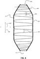
- FIG. 4 illustrates a diagram showing one embodiment of a substantially sinusoidal beaded weave pattern 400 to be deposited along the length of an example build layer of a 3D part being additively manufactured.
- the build layer is being viewed from above.
- FIG. 4 shows two previously deposited contours or boundaries 410 and 420 of the build layer.
- the width (in the width dimension 425) of the build layer varies along the length dimension 430 of the build layer. That is, following in the direction of the length dimension 430 from the top of FIG. 4 to the bottom of FIG. 4 , the build layer starts out narrow, gradually widens, stays at a maximum width for a while, and then gradually narrows.
- Other build layers having other variations of width over a length dimension are possible as well.
- the build layer between the contours 410 and 420 is filled in with a metal material as the beaded weave pattern 400 (e.g., starting at the top of FIG. 4 and ending at the bottom of FIG. 4 ).
- the computer control apparatus 76 is configured to control the robot 14 to move the deposition tool 60 along a planned path that results in the deposited beaded weave pattern 400 to fill in the build layer between the contours 410 and 420.
- the weave width 440 and the weave frequency of the beaded weave pattern 400 vary as the width of the build layer varies along the length dimension 430.
- a weave dwell of the beaded weave pattern 400 varies as the width of the build layer varies along the length dimension 430 during deposition.
- a travel speed of the deposition tool 60 in a deposition travel direction 450...e.g., from the top of FIG. 4 to the bottom of FIG. 4 ) varies as the width of the build layer varies along the length dimension 430 during deposition.
- the weave width, weave frequency, weave dwell, and travel speed are controlled by the computer control apparatus 76 during deposition, in accordance with a planned build pattern of the build layer.
- FIG. 5 illustrates a diagram showing one embodiment of a substantially triangular beaded weave pattern 500 to be deposited along the length of a build layer of a 3D part being additively manufactured.
- FIG. 6 illustrates a diagram showing one embodiment of a substantially rectangular beaded weave pattern 600 to be deposited along the length of a build layer of a 3D part being additively manufactured.
- Other beaded weave patterns having varying weave widths and weave frequencies are possible as well, in accordance with other embodiments.
- a bead is a metal deposition pass across a width of a build layer, and a beaded weave pattern is simply a series of metal deposition passes at locations along the planned path of a build layer for the beaded weave pattern.
- the deposited metal beads (passes) of the beaded weave pattern can have substantially similar or substantially different sizes (bead widths...e.g., see a bead width 460 in FIG. 4 ) and can be spaced similarly or differently from each other (e.g., see a bead spacing 470 in FIG. 4 ), depending on how the various parameters (weave width, weave frequency, weave dwell, and travel speed) are being dynamically adjusted.
- the bead width 460 may range from 4 mm to 12 mm over the length of a build layer.
- the weave width 440 is effectively the peak-to-peak amplitude of the weave pattern along any portion of the deposition (e.g., see FIG. 4 ).
- the weave frequency is the number of weave cycles per unit time (or per unit length along the travel direction 450) and is the inverse of the weave wavelength.
- the travel speed in the travel direction 450 along the length dimension 430 of the build layer is essentially an effective instantaneous linear travel speed along the length dimension 430 at any point in time during deposition, even though the deposition tool is actually travelling along the planned path (e.g., a sinusoidal path, a triangular path, or a rectangular path) for the beaded weave pattern.
- the weave dwell is a pause time at either end of the weave pattern. For example, when weaving left/right (as in FIGS. 4-6 ), the weave dwell is a pause time at the end of the left movement and then again at the end of the right movement.
- a weave frequency is 1 Hz
- the weave dwell is 0.2 seconds
- the weave dwell places heat at the edges of the beaded weave pattern.
- the weave dwell is set to allow metal to flow into the corner of the earlier bead and the previous layer, without bridging, which would leave a void.
- FIG. 7 illustrates a flowchart of one embodiment of a method 700 of filling a build layer of a 3D part being additively manufactured.
- a planned build pattern is accessed via a computer control apparatus (e.g., the computer control apparatus 76 of FIG. 1 ).
- the planned build pattern is one of multiple planned build patterns stored as digital data (e.g., in a storage subsystem of the computer control apparatus 76...e.g., see FIG. 15 ).
- the multiple planned build patterns correspond to multiple build layers of a three-dimensional (3D) part (e.g., 3D part 22 of FIG. 1 ) being additively manufactured.
- 3D three-dimensional
- a beaded weave pattern of metal material (e.g., beaded weave pattern 400 of FIG. 4 ) is deposited in a deposition travel direction 450 along a length dimension of a build layer of the multiple build layers.
- Deposition is accomplished via a metal deposition apparatus (e.g., the power supply 72, the wire feeder 68, and the deposition tool 60 of FIG. 1 ), under the control of the computer control apparatus (e.g., the computer control apparatus 76 of FIG. 1 ), in accordance with a planned path of the planned build pattern as a width of the build layer varies along the length dimension.
- a metal deposition apparatus e.g., the power supply 72, the wire feeder 68, and the deposition tool 60 of FIG. 1
- the computer control apparatus e.g., the computer control apparatus 76 of FIG. 1
- a weave width, a weave frequency, and a weave dwell of the beaded weave pattern are dynamically adjusted, along with a travel speed in the deposition travel direction 450, during deposition.
- the dynamic adjustments are performed under the control of the computer control apparatus (e.g., the computer control apparatus 76 of FIG. 1 ), in accordance with the planned build pattern, as the width varies along the length dimension.
- the result is a dynamically varying bead width of the beaded weave pattern (e.g., the beaded weave pattern 400 of FIG. 4 ).
- the dynamic adjustments to be made are predetermined. That is, the adjustments of the weave width, the weave frequency, the weave dwell, and the travel speed are not determined on-the-fly during an infilling process.
- the weave width, the weave frequency, the weave dwell, and the travel speed are dynamically adjusted during deposition in the method 700 to provide proper infilling of the build layer.
- the dynamic adjustments allow the bead width to widen or narrow to provide proper infilling and to allow maintenance of a substantially constant deposition rate of the metal material.
- the weave width is opened up, and the bead gets wider (and vice versa).
- the travel speed is reduced, the weave width is increased, the weave frequency is decreased (i.e., the weave wavelength is increased), and the weave dwell is increased.
- the travel speed is increased, the weave width is decreased, the weave frequency is increased (i.e., the weave wavelength is decreased), and the weave dwell is decreased.
- the dynamic increasing and decreasing of the weave parameters and the travel speed are determined ahead of time, as part of path planning development, and are not dynamically determined on-the-fly in real time, in accordance with one embodiment. However, there may be other embodiments in which on-the-fly, real time dynamic adjustments are performed.
- a substantially constant contact tip-to-work distance is maintained, during the depositing of the beaded weave pattern, under control of the computer control apparatus.
- CTWD contact tip-to-work distance
- U.S. Published Patent Application No. 2017/0252847 A1 which is incorporated herein by reference, discusses ways of controlling CTWD. Even though, during infill deposition, the travel speed and the weave parameters are dynamically changing, which may affect CTWD, the CTWD control process discussed in U.S. Published Patent Application No. 2017/0252847 A1 can be used to keep CTWD substantially constant, thus compensating for CTWD changes due to the dynamic deposition infill process.
- WFS wire feed speed
- the WFS may also be dynamically varied.
- not all of the parameters have to change at the same time during deposition of the beaded weave pattern.
- all of the parameters may be changed, or only some of the parameters (e.g., weave width and weave dwell) may be changed.
- the relationship of how the parameters dynamically change with respect to each other is determined ahead of time during path planning development for a build layer, to result in efficient and effective infill deposition of the build layer.
- the path planning software determines an area that needs to be filled across the current bead pass and dynamically adjusts the parameters (travel speed and weave parameters) for proper infilling of that area.
- Slicing software of G-code of the path planning software is involved with determining the area.
- the path planning software "knows" the location of the current bead pass on the build layer based on a CAD model of the 3D part to be additively manufactured, or digital data derived from scanning the 3D part.
- FIG. 8 illustrates a system block diagram of one embodiment of an additive manufacturing system 800 having a metal deposition apparatus 810, a computer control apparatus 820, and a robot 830 having a robot arm 835.
- the metal deposition apparatus 810 is configured to deposit molten metal material during an additive manufacturing process to form a part.
- the computer control apparatus 820 is operatively coupled to the metal deposition apparatus 810 and the robot 830. That is, in the embodiment of FIG. 8 , the computer control apparatus 820 is configured to control various aspects of the metal deposition apparatus 810 (e.g., wire feeding, output power or energy) and to serve as a motion controller for the robot 830.
- various aspects of the metal deposition apparatus 810 e.g., wire feeding, output power or energy
- the computer control apparatus 820 may include two or more controllers (e.g., a first controller to control the metal deposition apparatus 810 and a second controller to control the robot 830).
- the robot arm 835 is coupled to the metal deposition apparatus 810 (or to at least a portion of the metal deposition apparatus 810 such as a deposition tool) such that the robot 830 can move the metal deposition apparatus 810 in space, via the arm 835, relative to a base or substrate under control of the computer control apparatus 820.
- the robot arm 835 is coupled to the base or substrate such that the robot 830 can move the base or substrate in space, via the arm 835, relative to the metal deposition apparatus 810.
- the computer control apparatus 820 commands the metal deposition apparatus 810 to deposit a molten metal material on a base (substrate) during a contour deposition phase of an additive manufacturing process to form a contour of a part.
- the computer control apparatus 820 then commands the metal deposition apparatus 810 to deposit the metal material on the base during an infill pattern deposition phase of the additive manufacturing process to form a beaded weave pattern within a region outlined by the contour of the part.
- the deposition rate of the contour deposition phase is less than a deposition rate of the infill pattern deposition phase, in accordance with one embodiment, allowing the contour to be deposited more accurately and more precisely than the infill pattern.
- the metal material is deposited on a previous layer of the contour and infill pattern, for example.
- FIG. 9 illustrates a portion of an alternative embodiment of the additive manufacturing system 800 of FIG. 8 , where the robot 830 is operatively connected to a platform 910 holding a 3D part or substrate 920 instead of being connected to the metal deposition apparatus 810.
- the metal deposition apparatus 810 and the robot 830 may be of the types shown in FIG. 1 and FIG. 9 , for example, in accordance with certain embodiments.
- Other types of robots and metal deposition apparatuses are possible as well, in accordance with other various embodiments.
- FIGS. 10-14 show various embodiments of metal deposition apparatuses as discussed below herein.
- FIG. 10 illustrates a system block diagram of one embodiment 1000 of the metal deposition apparatus 810 of FIG. 8 that is consumable electrode based and which includes a power source 1010 and a wire feeder 1020 that are controlled by the computer control apparatus 820 of FIG. 8 .
- the metal deposition apparatus 1000 also includes a deposition tool 1025 (e.g., a welding torch or gun having a contact tip 1027).
- the metal deposition apparatus 1000 may have elements and/or combinations of elements that are similar that of FIGS. 1-2 , for example, in accordance with certain embodiments.
- the wire feeder 1020 is configured to feed a consumable wire electrode 1030 of a metal material through the deposition tool 1025 and toward a base or part 1040.
- the power source 1010 and the deposition tool 1025 are operatively connected to the wire feeder 1020.
- the power source 1010 and the wire feeder 1020 are configured to provide energy via the consumable wire electrode 1030 (forming an electric arc 1035 between the electrode 1030 and the base/part 1040) to melt the consumable wire electrode 1030 (and possibly part of the base 1040) during an additive manufacturing process.
- Electrical contact to the consumable wire electrode 1030 is made via the contact tip 1027 of the deposition tool 1025.
- the robot 830 of FIG. 8 may move the metal deposition apparatus 1000 (or just the deposition tool 1025), or the base/part 1040 to deposit a beaded weave pattern under the control of the computer control apparatus 820 as discussed herein. Again, as the additive manufacturing process continues to build successive build layers of the part, the metal material is deposited on a previous build layer, for example, in a similar manner.
- FIG. 11 illustrates a system block diagram of one embodiment 1100 of the metal deposition apparatus 810 of FIG. 8 that is laser based and which includes a power source 1110, a wire feeder 1120, and a laser device 1130 that are controlled by the computer control apparatus 820 of FIG. 8 .
- the metal deposition apparatus 1100 is configured to deposit a metal filler wire during an additive manufacturing process.
- the laser device 1130 and the wire feeder 1120 may constitute a deposition tool.
- the laser device 1130 may constitute a deposition tool.
- the metal deposition apparatus 1100 may have elements and/or combinations of elements that are similar that of FIGS. 1-2 , for example, in accordance with certain embodiments.
- the wire feeder 1120 is configured to feed a filler wire 1140 of a metal material toward a base or part 1040.
- the embodiment of the metal deposition apparatus 1100 of FIG. 11 also includes a power source 1110 and a laser device 1130 operatively connected to the power source 1110.
- the power source 1110 and the laser device 1130 are configured to provide energy (in the form of a laser beam 1135) to melt the filler wire 1140 (and possibly part of the base or part 1040) during an additive manufacturing process.
- the robot 830 of FIG. 8 may move the metal deposition apparatus 1100 (or just the laser device 1130), or the base/part 1040 to deposit a beaded weave pattern under the control of the computer control apparatus 820 as discussed herein. Again, as the additive manufacturing process continues to build successive build layers of the part, the metal material is deposited on a previous build layer, for example, in a similar manner.
- an additive manufacturing system having a metal deposition apparatus may be configured as a laser hot wire (LHW) system 1200 as in FIG. 12 .
- the system 1200 of FIG. 12 includes an exemplary embodiment of a combination filler wire feeder and an energy source.
- the system 1200 includes a laser subsystem capable of focusing a laser beam 1210 onto a base/substrate or part 1215 to heat the base/substrate or part 1215.
- the laser subsystem is a high intensity energy source.
- the laser subsystem can be any type of high energy laser source, including but not limited to carbon dioxide, Nd:YAG, Yb-disk, YB-fiber, fiber delivered, or direct diode laser systems.
- the laser subsystem is a low intensity energy source (e.g., to soften or minimally melt a metal material).
- the laser subsystem includes a laser device 1220 and a laser power supply 1230 operatively connected to each other.
- the laser power supply 1230 provides power to operate the laser device 1220.
- the system 1200 also includes a hot filler wire feeder subsystem capable of providing at least one resistive filler wire 1240 to make contact with the base/substrate or part 1215 in the vicinity of the laser beam 1210.
- the wire feeder subsystem includes a filler wire feeder 1250, a contact tube 1260, and a power supply 1270.
- the filler wire 1240 is resistance-heated by electrical current from the power supply 1270 which is operatively connected between the contact tube 1260 and the base/substrate or part 1215.
- the power supply 1270 is a pulsed direct current (DC) power supply, although alternating current (AC) or other types of power supplies are possible as well.
- DC direct current
- AC alternating current
- the wire 1240 is fed from the filler wire feeder 1250 through the contact tube 1260 toward the base/substrate or part 1215 and extends beyond the tube 1260.
- the extension portion of the wire 1240 is resistance-heated such that the extension portion approaches or reaches the melting point before contacting the base/substrate or part 1215.
- the laser beam 1210 may serve to melt some of the base metal of the base/substrate or part 1215 to form a puddle and/or can also be used to melt the wire 1240 onto the base/substrate or part 1215.
- the power supply 1270 provides energy needed to resistance-melt the filler wire 1240. In some embodiments the power supply 1270 provides all of the energy needed while in other embodiments the laser or other energy heat source can provide some of the energy.
- the system 1200 further includes a motion control subsystem capable of moving the laser beam 1210 (energy source) and the resistive filler wire 1240 in a same controlled direction (e.g., a beaded weave pattern) along the base/substrate or part 1215 (at least in a relative sense) such that the laser beam 1210 and the resistive filler wire 1240 remain in a fixed relation to each other.
- a motion control subsystem capable of moving the laser beam 1210 (energy source) and the resistive filler wire 1240 in a same controlled direction (e.g., a beaded weave pattern) along the base/substrate or part 1215 (at least in a relative sense) such that the laser beam 1210 and the resistive filler wire 1240 remain in a fixed relation to each other.
- the resistive filter wire 1240 may be fed through a deposition tool housing the laser device 1220 and the contact tube 1260.
- the relative motion between the base/substrate or part 1215 and the laser/wire combination may be achieved by actually moving the base/substrate or part 1215 or by moving a deposition tool having, for example, the laser device 1220 and at least a portion of the wire feeder subsystem (e.g., the contact tube 1260).
- the laser device 1220 and the contact tube 1260 may be integrated into a single deposition tool.
- the deposition tool may be moved along the base/substrate or part 1215 via a motion control subsystem operatively connected to the deposition tool.
- the motion control subsystem includes a computer control apparatus 1280 operatively connected to a robot 1290 having a platform 1293 (e.g., a rotatable platform and/or a translatable platform).
- the computer control apparatus 1280 controls the motion of the robot 1290.
- the robot 1290 is operatively connected (e.g., mechanically secured) to the base/substrate or part 1215 via the platform 1293 to move the base/substrate or part 1215 in, for example, a beaded weave pattern such that the laser beam 1210 and the wire 1240 effectively travel along the base/substrate or part 1215.
- the robot 1290 driving the platform 1293 may be driven electrically, pneumatically, or hydraulically, in accordance with various embodiments.
- the motion control subsystem, including the computer control apparatus 1280 and the robot 1290 are a separate part of an additive manufacturing system and are not part of the metal deposition apparatus.
- the additive manufacturing system 1200 further includes a sensing and current control subsystem 1295 which is operatively connected to the base/substrate or part 1215 and the contact tube 1260 (i.e., effectively connected to the output of the power supply 1270) and is capable of measuring a potential difference (i.e., a voltage V) between and a current (I) through the base/substrate or part 1215 and the wire 1240.
- the sensing and current control subsystem 1295 is capable of sensing when the resistive filler wire 1240 is in contact with the base/substrate or part 1215 and is operatively connected to the power supply 1270 to be further capable of controlling the flow of current through the resistive filler wire 1240 in response to the sensing.
- the sensing and current controller 1295 may be an integral part of the power supply 1270.
- FIG. 13 illustrates a system block diagram of one embodiment 1300 of the metal deposition apparatus 810 of FIG. 8 that is non-consumable electrode based and which includes a power source 1310, a wire feeder 1320, and a non-consumable electrode 1330 (e.g., a tungsten electrode) that are at least partially controlled by the computer control apparatus 820 of FIG. 8 .
- the metal deposition apparatus 1300 is configured to deposit a metal filler wire during an additive manufacturing process.
- the metal deposition apparatus 1300 may have elements and/or combinations of elements that are similar that of FIGS. 1-2 , for example, in accordance with certain embodiments.
- the wire feeder 1320 is configured to feed a filler wire 1325 of a metal material toward a base 1040.
- the non-consumable electrode 1330 is operatively connected to the power source 1310.
- the power source 1310 and the non-consumable electrode 1330 are configured to provide energy (in the form of a plasma beam or arc 1335) to melt the filler wire 1325 (and possibly part of the base or part 1040) during an additive manufacturing process to deposit, for example, a beaded weave pattern.
- the computer control apparatus 820 is operatively connected to the wire feeder 1320 and the power source 1310 to provide at least partial control thereof. Again, as the additive manufacturing process continues to build successive build layers of the part, the metal material is deposited on a previous build layer, for example, in a similar manner.
- FIG. 14 illustrates a system block diagram of one embodiment 1400 of the metal deposition apparatus 810 of FIG. 8 that is both consumable electrode based and filler wire based, and which includes a power source 1410, a first wire feeder 1420, and a second wire feeder 1430 that are controlled, at least partially, by the computer control apparatus 820 of FIG. 8 .
- the metal deposition apparatus 1400 also includes a deposition tool 1425 (e.g., a welding torch or gun having a contact tip 1427).
- the metal deposition apparatus 1400 may have elements and/or combinations of elements that are similar that of FIGS. 1-2 , for example, in accordance with certain embodiments.
- the second wire feeder 1430 is configured to feed a filler wire 1435 of a metal material toward a base or part 1040.
- the first wire feeder 1420 is operatively connected to the power source 1410 and is configured to feed a consumable wire electrode 1450 toward the base or part 1040.
- the power source 1410 and the first wire feeder 1420 are configured to provide energy via the consumable wire electrode 1450 (forming an electric arc 1460 between the electrode 1450 and the base or part 1040) to melt the filler wire 1435 and the consumable wire electrode 1450 (and possibly part of the base or part 1040) during an additive manufacturing process.
- the computer control apparatus 820 is operatively connected to the first wire feeder 1420, the second wire feeder 1430, and the power source 1410 providing at least partial control thereof. Again, as the additive manufacturing process continues to build successive build layers of the part, the metal material is deposited on a previous build layer, for example, in a similar manner.
- FIG. 15 illustrates one embodiment of an example computer control apparatus (or controller) 1500 of the systems of FIGS. 1 , 2 , 8 , 10 , 11 , 12 , 13 , and 14 .
- the computer control apparatus (or controller) 1500 includes at least one processor 1514 which communicates with a number of peripheral devices via bus subsystem 1512. These peripheral devices may include a storage subsystem 1524, including, for example, a memory subsystem 1528 and a file storage subsystem 1526, user interface input devices 1522, user interface output devices 1520, and a network interface subsystem 1516.
- the input and output devices allow user interaction with the computer control apparatus (or controller) 1500.
- Network interface subsystem 1516 provides an interface to outside networks and is coupled to corresponding interface devices in other computer systems.
- the computer control apparatus 76 of the system 10 may share one or more characteristics with the computer control apparatus (or controller) 1500 and may be, for example, a conventional computer, a digital signal processor, and/or other computing device.
- User interface input devices 1522 may include a keyboard, pointing devices such as a mouse, trackball, touchpad, or graphics tablet, a scanner, a touchscreen incorporated into the display, audio input devices such as voice recognition systems, microphones, and/or other types of input devices.
- pointing devices such as a mouse, trackball, touchpad, or graphics tablet
- audio input devices such as voice recognition systems, microphones, and/or other types of input devices.
- use of the term "input device” is intended to include all possible types of devices and ways to input information into the computer control apparatus (or controller) 1500 or onto a communication network.
- User interface output devices 1520 may include a display subsystem, a printer, a fax machine, or non-visual displays such as audio output devices.
- the display subsystem may include a cathode ray tube (CRT), a flat-panel device such as a liquid crystal display (LCD), a projection device, or some other mechanism for creating a visible image.
- the display subsystem may also provide non-visual display such as via audio output devices.
- output device is intended to include all possible types of devices and ways to output information from the computer control apparatus (or controller) 1500 to the user or to another machine or computer system.
- Storage subsystem 1524 stores programming and data constructs that provide or support some or all of the functionality described herein (e.g., as software modules).
- the storage subsystem 1524 may include a CAD model of a 3D part to be additively manufactured and multiple planned build patterns corresponding to multiple build layers of the 3D part.
- Memory 1528 used in the storage subsystem can include a number of memories including a main random access memory (RAM) 1530 for storage of instructions and data during program execution and a read only memory (ROM) 1532 in which fixed instructions are stored.
- a file storage subsystem 1526 can provide persistent storage for program and data files, and may include a hard disk drive, a floppy disk drive along with associated removable media, a CD-ROM drive, an optical drive, or removable media cartridges.
- the modules implementing the functionality of certain embodiments may be stored by file storage subsystem 1526 in the storage subsystem 1524, or in other machines accessible by the processor(s) 1514.
- Bus subsystem 1512 provides a mechanism for letting the various components and subsystems of the computer control apparatus (or controller) 1500 communicate with each other as intended. Although bus subsystem 1512 is shown schematically as a single bus, alternative embodiments of the bus subsystem may use multiple buses.
- the computer control apparatus (or controller) 1500 can be of varying types including a workstation, server, computing cluster, blade server, server farm, or any other data processing system or computing device. Due to the ever-changing nature of computing devices and networks, the description of the computer control apparatus (or controller) 1500 depicted in FIG. 15 is intended only as a specific example for purposes of illustrating some embodiments. Many other configurations of the computer control apparatus (or controller) 1500 are possible, having more or fewer components than the computer control apparatus (or controller) depicted in FIG. 15 .
Abstract
Description
- The invention is related to an additive manufacturing system according to
claim 1 and to a method of filling a build layer of an additively manufactured part according to claim 7.U.S. Published Patent Application No. 2017/0252847 A1 published on September 7, 2017 is incorporated herein by reference in its entirety. - Embodiments of the present invention relate to systems and methods related to additive manufacturing, and more specifically to systems and methods supporting metal filling of a build layer during an additive manufacturing process
- Conventionally, additive manufacturing processes are able to make near net shape parts at relatively low deposition rates where each part is built up layer-by-layer. However, build times can be long, and present infill techniques can be inadequate for additively manufacturing certain types of parts (e.g., parts where the width of a build layer varies).
- In order to optimize additive manufacturing, especially with respect to build time, an additive manufacturing system according to
claim 1 is described and a method of filling a build layer of an additively manufactured part according to claim 7. Preferred embodiments are subject of the subclaims. Embodiments of the present invention include systems and methods related to additive manufacturing that provide for the efficient infilling of build layers of a three-dimensional (3D) part during additive manufacturing. - In one embodiment, an additive manufacturing system is provided. Patterns of multiple layers of a 3D part to be additively manufactured are represented and stored as digital data within the system, in accordance with one embodiment. The digital data may be from a CAD model or from a scanned part, for example. The system includes a computer control apparatus configured to access multiple planned build patterns stored as digital data and corresponding to multiple build layers of a three-dimensional (3D) part to be additively manufactured. The system also includes a metal deposition apparatus configured to deposit metal material to form at least a portion of a build layer of the multiple build layers of the 3D part. The metal material is deposited as a beaded weave pattern, in accordance with a planned path of a planned build pattern of the multiple planned build patterns, under control of the computer control apparatus, where the planned build pattern corresponds to the build layer. A weave width, a weave frequency, and a weave dwell of the beaded weave pattern, and/or a travel speed in a deposition travel direction along a length dimension of the build layer, are dynamically adjusted during deposition of the beaded weave pattern. The adjustments are made under control of the computer control apparatus in accordance with the planned build pattern, as a width of the build layer varies along the length dimension of the build layer. The result is a dynamically varying bead width of the beaded weave pattern. In one embodiment, a robot is operatively connected to at least a portion of the metal deposition apparatus. The robot is configured to be controlled by the computer control apparatus during the deposition of the beaded weave pattern to move at least the portion of the metal deposition apparatus relative to the 3D part being additively manufactured in accordance with the planned path of the planned build pattern. In one embodiment, a robot is operatively connected to a base holding the 3D part being additively manufactured. The robot is configured to be controlled by the computer control apparatus during the deposition of the beaded weave pattern to move the base relative to the metal deposition apparatus in accordance with the planned path of the planned build pattern. In one embodiment, the metal deposition apparatus includes a deposition tool having a contact tip, a wire feeder configured to feed a consumable wire electrode of the metal material toward the 3D part through the deposition tool, and a power source operatively connected to the wire feeder. The power source is configured to provide energy to melt at least the consumable wire electrode during the deposition of the beaded weave pattern by forming an arc between the consumable wire electrode and the 3D part. In one embodiment, the metal deposition apparatus includes a wire feeder configured to feed a filler wire of the metal material toward the 3D part, a power source, and a laser operatively connected to the power source. The power source and the laser are configured to provide energy in the form of a laser beam to melt at least the filler wire during the deposition of the beaded weave pattern. In one embodiment, the metal deposition apparatus includes a wire feeder configured to feed a filler wire of the metal material toward the 3D part, a power source, and a non-consumable electrode operatively connected to the power source. The power source and the non-consumable electrode are configured to provide energy to melt at least the filler wire during the deposition of the beaded weave pattern by forming an arc between the non-consumable electrode and the 3D part. In one embodiment, the metal deposition apparatus includes a first wire feeder configured to feed a filler wire of the metal material toward the 3D part, a power source, and a second wire feeder operatively connected to the power source and configured to feed a consumable wire electrode of the metal material toward the 3D part. The power source is configured to provide energy to melt at least the consumable wire electrode and the filler wire during the deposition of the beaded weave pattern by forming an arc between the consumable wire electrode and the 3D part. In one embodiment, a substantially constant metal deposition rate of the metal material is maintained during the deposition of the beaded weave pattern under control of the computer control apparatus. In one embodiment, a substantially constant contact tip-to-work distance (CTWD) is maintained during the deposition of the beaded weave pattern under control of the computer control apparatus. A wave shape of the beaded weave pattern may be, for example, one of a substantially sinusoidal shape, a substantially triangular shape, or a substantially rectangular shape, based on the planned build pattern, in accordance with various embodiments.
- One embodiment includes an additive manufacturing method of filling a build layer of an additively manufactured part. The method includes accessing a planned build pattern of multiple planned build patterns, stored as digital data, via a computer control apparatus. The multiple planned build patterns correspond to multiple build layers of a three-dimensional (3D) part being additively manufactured. The method further includes depositing a beaded weave pattern of metal material in a deposition travel direction along a length dimension of a build layer of the multiple build layers, via a metal deposition apparatus. The deposition is under the control of the computer control apparatus and is performed in accordance with a planned path of the planned build pattern as a width of the build layer varies along the length dimension. The method also includes dynamically adjusting at least one of a weave width, a weave frequency, and a weave dwell of the beaded weave pattern, and/or a travel speed in the deposition travel direction during deposition. The adjustments are made under the control of the computer control apparatus, in accordance with the planned build pattern, as the width varies along the length dimension. The result is a dynamically varying bead width of the beaded weave pattern. In one embodiment, the method includes controlling a robot, operatively connected to at least a portion of the metal deposition apparatus, via the computer control apparatus during the depositing of the beaded weave pattern to move at least the portion of the metal deposition apparatus relative to the 3D part being additively manufactured in accordance with the planned path of the planned build pattern. In one embodiment, the method includes controlling a robot, operatively connected to a base holding the 3D part being additively manufactured, via the computer control apparatus during the deposition of the beaded weave pattern to move the base relative to the metal deposition apparatus in accordance with the planned path of the planned build pattern. In one embodiment, the method includes feeding a consumable wire electrode of the metal material toward the 3D part via a wire feeder of the metal deposition apparatus. Energy is provided to melt at least the consumable wire electrode, via a power source of the metal deposition apparatus operatively connected to the wire feeder, during the depositing of the beaded weave pattern by forming an arc between the consumable wire electrode and the 3D part. In one embodiment, the method includes feeding a filler wire of the metal material toward the 3D part via a wire feeder of the metal deposition apparatus. Energy is provided to melt at least the filler wire during the depositing of the beaded weave pattern, via a power source of the metal deposition apparatus operatively connected to a laser of the metal deposition apparatus, by forming a laser beam between the laser and the 3D part. In one embodiment, the method includes feeding a filler wire of the metal material toward the 3D part via a wire feeder of the metal deposition apparatus. Energy is provided to melt at least the filler wire during the depositing of the beaded weave pattern, via a power source of the metal deposition apparatus operatively connected to a non-consumable electrode of the metal deposition apparatus, by forming an arc between the non-consumable electrode and the 3D part. In one embodiment, the method includes feeding a filler wire of the metal material toward the 3D part via a first wire feeder of the metal deposition apparatus, and feeding a consumable wire electrode of the metal material toward the 3D part via a second wire feeder of the metal deposition apparatus. Energy is provided to melt at least the consumable wire electrode and the filler wire during the depositing of the beaded weave pattern, via a power source of the metal deposition apparatus operatively connected to the second wire feeder, by forming an arc between the consumable wire electrode and the 3D part. In one embodiment, the method includes maintaining a substantially constant metal deposition rate of the metal material, during the depositing of the beaded weave pattern, under control of the computer control apparatus. In one embodiment, the method includes maintaining a substantially constant contact tip-to-work distance (CTWD), during the depositing of the beaded weave pattern, under control of the computer control apparatus. A wave shape of the beaded weave pattern may be, for example, one of a substantially sinusoidal shape, a substantially triangular shape, or a substantially rectangular shape, based on the planned build pattern, in accordance with various embodiments.
- Numerous aspects of the general inventive concepts will become readily apparent from the following detailed description of exemplary embodiments, from the claims, and from the accompanying drawings.
- The accompanying drawings, which are incorporated in and constitute a part of the specification, illustrate various embodiments of the disclosure. It will be appreciated that the illustrated element boundaries (e.g., boxes, groups of boxes, or other shapes) in the figures represent one embodiment of boundaries. In some embodiments, one element may be designed as multiple elements or that multiple elements may be designed as one element. In some embodiments, an element shown as an internal component of another element may be implemented as an external component and vice versa. Furthermore, elements may not be drawn to scale.
-
FIG. 1 illustrates one embodiment of an additive manufacturing system which includes a metal deposition apparatus; -
FIG. 2 illustrates a schematic block diagram of one embodiment of a power source of the additive manufacturing system ofFIG. 1 operatively connected to a consumable wire electrode; -
FIG. 3 illustrates a diagram showing one embodiment of generating an arc between a welding electrode and a build layer of a 3D part being additively manufactured; -
FIG. 4 illustrates a diagram showing one embodiment of a substantially sinusoidal beaded weave pattern to be deposited along the length of a build layer of a 3D part being additively manufactured; -
FIG. 5 illustrates a diagram showing one embodiment of a substantially triangular beaded weave pattern to be deposited along the length of a build layer of a 3D part being additively manufactured; -
FIG. 6 illustrates a diagram showing one embodiment of a substantially rectangular beaded weave pattern to be deposited along the length of a build layer of a 3D part being additively manufactured; -
FIG. 7 illustrates a flowchart of one embodiment of a method of filling a build layer of a 3D part being additively manufactured; -
FIG. 8 illustrates a system block diagram of one embodiment of an additive manufacturing system having a metal deposition apparatus, a computer control apparatus, and a robot having a robot arm; -
FIG. 9 illustrates a portion of an alternative embodiment of the additive manufacturing system ofFIG. 8 , where the robot is operatively connected to a platform holding a 3D part or substrate, instead of being connected to the metal deposition apparatus; -
FIG. 10 illustrates a system block diagram of one embodiment of the metal deposition apparatus ofFIG. 8 that is consumable electrode based; -
FIG. 11 illustrates a system block diagram of one embodiment of the metal deposition apparatus ofFIG. 8 that is laser based; -
FIG. 12 illustrates a system block diagram of one embodiment, having similarities toFIG. 11 , of an additive manufacturing system having a metal deposition apparatus configured as a laser hot wire (LHW) system; -
FIG. 13 illustrates a system block diagram of one embodiment of the metal deposition apparatus ofFIG. 8 that is non-consumable electrode based; -
FIG. 14 illustrates a system block diagram of one embodiment of the metal deposition apparatus ofFIG. 8 that is both consumable electrode based and filler wire based; and -
FIG. 15 illustrates one embodiment of an example computer control apparatus or controller of the systems ofFIGS. 1 ,2 ,8 ,10 ,11 ,12 ,13 , and14 . - As is generally known, additive manufacturing is a process in which a material is deposited onto a base/substrate or part (e.g., in layers) so as to create a desired manufactured product. Patterns of multiple layers of a three-dimensional (3D) part to be additively manufactured are represented and stored as digital data, in accordance with one embodiment. The digital data may be from a CAD model or from a scanned part, for example. In some applications the article of manufacture can be quite complex. However, known methods and systems used for filling in additive manufacturing tend to be slow and have limited performance. Embodiments of the present invention address the filling issues by providing systems and methods that deposit a dynamic beaded weave pattern during filling.
- Embodiments of additive manufacturing systems and methods are disclosed. In one embodiment, an additive manufacturing system includes a computer control apparatus configured to access multiple planned build patterns stored as digital data and corresponding to multiple build layers of a three-dimensional (3D) part to be additively manufactured. The system also includes a metal deposition apparatus. The metal deposition apparatus is configured to deposit a beaded weave pattern of metal material along a length dimension of a build layer, of the multiple build layers of the 3D part, as a width of the build layer varies along the length dimension. The deposition is under the control of the computer control apparatus in accordance with a planned path of a planned build pattern of the multiple planned build patterns. A weave width, a weave frequency, and a weave dwell of the beaded weave pattern, and a travel speed of the metal deposition apparatus along the length dimension, are dynamically adjusted during deposition of the beaded weave pattern as the width varies along the length dimension. The dynamic adjustment is under the control of the computer control apparatus in accordance with the planned build pattern, resulting in a dynamically varying bead width of the beaded weave pattern. The planned build pattern and, therefore, the planned path and the dynamic adjustments are generated ahead of time as part of path planning development using path planning software.
- Embodiments of a metal deposition apparatus may include, for example, at least one of a laser-based subsystem, a plasma based subsystem, an arc based subsystem, an electron beam based subsystem, or an electric resistance based subsystem, for example, to deposit a metal material by melting a metal wire. Furthermore, some embodiments of a metal deposition apparatus may include, for example, a wire delivery or feeding system to feed/deliver a consumable metal wire to additively manufacture a 3D part on a base. Also, some embodiments of a metal deposition apparatus may include, for example, kinematic control elements (e.g., robotics) or other types of control elements (e.g., optical control elements) to move a laser beam, a plasma beam, an electric arc, an electron beam, or a consumable metal wire with respect to a 3D part being additively manufactured on a base or a substrate.
- The examples and figures herein are illustrative only and are not meant to limit the subject invention, which is measured by the scope and spirit of the claims. Referring now to the drawings, wherein the showings are for the purpose of illustrating exemplary embodiments of the subject invention only and not for the purpose of limiting same,
FIG. 1 puts embodiments of the subject invention in context by illustrating one embodiment of an additive manufacturing system which includes a metal deposition apparatus. It is envisioned that the metal deposition apparatus may typically be used to help additively manufacture a part, layer-by-layer, by a welding process such as, for example, gas metal arc welding (GMAW), flux-cored arc welding (FCAW), or gas tungsten arc welding (GTAW). Other metal deposition processes are possible as well, in accordance with other embodiments, as discussed later herein. - Referring to
FIG. 1 , the additive manufacturing system 10 generally includes a frame 12, arobot 14 disposed within the frame, and first and second tables 16 and 18, respectively, also disposed within the frame. The additive manufacturing system 10 is useful for additively manufacturing parts (e.g., 22 and 24) in a manner that will be described in more detail below herein. In the depicted embodiment ofFIG. 1 , the frame 12 includes a plurality of side walls and doors to enclose therobot 14 and the tables 16 and 18. Even though a substantially rectangular configuration in plan view is shown, the frame 12, and the system 10, can take numerous configurations. - A
front access door 26 mounts to the frame 12 to provide access to the interior of the frame. Thefront access door 26 can take a bi-fold configuration where the door includes two hinge sets: a first hinge set attaching thedoor 26 to the frame 12 and a second hinge set attaching one panel of the door to another panel. Nevertheless, thefront access door 26 can take other configurations such as a sliding door or a swinging door. Similarly, arear access door 28 also mounts to the frame 12. Therear access door 28 in the depicted embodiment also takes a bi-fold configuration; however, the rear access door can take other configurations such as those discussed with reference to thefront access door 26.Windows 32 can be provided on either door (only depicted on front door 26). The windows can include a tinted safety screen, which is known in the art. - A
control panel 40 is provided on the frame 12 adjacent thefront door 26. Control knobs and/or switches provided on thecontrol panel 40 communicate with controls housed in acontrols enclosure 42 that is also mounted to the frame 12. The controls on thecontrol panel 40 can be used to control operations performed in the additive manufacturing system 10 in a similar manner to controls used with known additive manufacturing systems. - In one embodiment, the
robot 14 mounts on a pedestal that mounts on a support. Therobot 14 in the depicted embodiment is centered with respect to the tables 16 and 18 and includes multiple axes of movement. If desired, the pedestal can rotate with respect to the support, similar to a turret. Accordingly, some sort of drive mechanism, e.g., a motor and transmission (not shown), can be housed in the pedestal and/or the support for rotating therobot 14. - In one embodiment, a
deposition tool 60 is part of the metal deposition apparatus and attaches to a distal end of an arm of therobot 14. Thedeposition tool 60 may include, for example, a welding gun or torch having a contact tip, a laser device, or a non-consumable electrode device, in accordance with embodiments discussed later herein. Thedeposition tool 60 allows for deposition of metal material. In one embodiment, a flexible tube orconduit 62 attaches to thedeposition tool 60. A consumable metal wire 64 (e.g., used as a wire electrode or a filler wire), which can be stored in acontainer 66, is delivered to thedeposition tool 60 through theconduit 62. In one embodiment, awire feeder 68 is part of the metal deposition apparatus and attaches to the frame 12 to facilitate the delivery of theconsumable metal wire 64 to thedeposition tool 60. - Even though the
robot 14 is shown mounted to a base or lower portion of the frame 12, if desired, therobot 14 can mount to an upper structure of the frame and depend downwardly into the system 10. In one embodiment, a power supply 72 (power source) is part of the metal deposition apparatus for supporting an additive manufacturing operation and mounts to and rests on aplatform 74 that is connected to and can be a part of the frame 12. In another embodiment, thepower supply 72 may be implemented as two separate power supplies (e.g., one for powering a laser in thedeposition tool 60 and another for heating theconsumable metal wire 64 as it passes through the deposition tool 60). A computer control apparatus 76 communicates with and controls various portions of the additive manufacturing system 10 (including the robot 14), as discussed later herein, and rests and mounts on theplatform 74. -
FIG. 2 illustrates a schematic block diagram of an exemplary embodiment of apower source 72 of the additive manufacturing system 10 ofFIG. 1 operatively connected to aconsumable wire electrode 64. Thepower source 72 includes a switchingpower supply 105 having apower conversion circuit 110 and abridge switching circuit 180 providing welding output power between thewire 64 and theworkpiece part 22 to melt thewire 64 during deposition by forming an arc between thewire 64 and thepart 22. Thepower conversion circuit 110 may be transformer based with a half bridge output topology. For example, thepower conversion circuit 110 may be of an inverter type that includes an input power side and an output power side, for example, as delineated by the primary and secondary sides, respectively, of a welding transformer. Other types of power conversion circuits are possible as well such as, for example, a chopper type having a DC output topology. Thepower source 72 also includes abridge switching circuit 180 that is operatively connected to thepower conversion circuit 110 and is configured to switch a direction of the polarity of the welding output current (e.g., for AC operation). - The
power source 72 further includes awaveform generator 120 and acontroller 130. Thewaveform generator 120 generates welding waveforms at the command of thecontroller 130. A waveform generated by thewaveform generator 120 modulates the output of thepower conversion circuit 110 to produce the output current between thewire 64 and theworkpiece part 22. Thecontroller 130 also commands the switching of thebridge switching circuit 180 and may provide control commands to the power theconversion circuit 110. - In one embodiment, the
power source 72 further includes avoltage feedback circuit 140 and acurrent feedback circuit 150 to monitor the output voltage and current between thewire 64 and theworkpiece part 22 and provide the monitored voltage and current back to thecontroller 130. The feedback voltage and current may be used by thecontroller 130 to make decisions with respect to modifying the welding waveform generated by thewaveform generator 120 and/or to make other decisions that affect operation of thepower source 72, for example. - In accordance with one embodiment, the switching
power supply 105, thewaveform generator 120, thecontroller 130, thevoltage feedback circuit 140, and thecurrent feedback circuit 150 constitute thepower source 72. The additive manufacturing system 10 also includes awire feeder 68 that feeds theconsumable metal wire 64 toward theworkpiece part 22 through thedeposition tool 60 at a selected wire feed speed (WFS), in accordance with one embodiment. Thewire feeder 68, theconsumable metal wire 64, and theworkpiece part 22 are not part of thepower source 72 but may be operatively connected to thepower source 72 via one or more output cables, for example. -
FIG. 3 illustrates a diagram showing one embodiment of generating an arc between a consumable metal wire 64 (coming out of a deposition tool 60) and a3D part 22 being additively manufactured. As seen inFIG. 3 , a build layer N and a build layer N+1 of thepart 22 have been deposited by melting theconsumable metal wire 64 via the arc. An arc length and a contact tip-to-work distance (CTWD) are also shown inFIG. 3 . In accordance with one embodiment, a substantially constant CTWD is controlled and maintained during deposition, as discussed later herein.U.S. Patent No. 9,815,135 - In accordance with another embodiment, the
deposition tool 60 includes a laser device and thepower source 72 is configured to provide power (energy) to the laser device to form a laser beam to melt the consumable metal wire 64 (e.g., a filler wire) during deposition. In accordance with yet another embodiment, thedeposition tool 60 includes a non-consumable electrode (e.g., a tungsten electrode) and thepower source 72 is configured to provide power (energy) to melt the consumable metal wire 64 (e.g., a filler wire) during deposition by forming an arc between the non-consumable electrode and the part. In some embodiments, theconsumable metal wire 64 is fed through thedeposition tool 60, where thedeposition tool 60 includes, for example, a contact tip, a laser device, or a non-consumable electrode. In other embodiments, theconsumable metal wire 64 may not be fed through thedeposition tool 60 having a contact tip, a laser device, or a non-consumable electrode. Instead, theconsumable metal wire 64 may be fed from an adjacent position and toward an output of such adeposition tool 60, as discussed later herein with respect to at leastFIGS. 11-13 . -
FIG. 4 illustrates a diagram showing one embodiment of a substantially sinusoidalbeaded weave pattern 400 to be deposited along the length of an example build layer of a 3D part being additively manufactured. InFIG. 4 , the build layer is being viewed from above.FIG. 4 shows two previously deposited contours orboundaries length dimension 430 of the build layer. That is, following in the direction of thelength dimension 430 from the top ofFIG. 4 to the bottom ofFIG. 4 , the build layer starts out narrow, gradually widens, stays at a maximum width for a while, and then gradually narrows. Other build layers having other variations of width over a length dimension are possible as well. - The build layer between the
contours FIG. 4 and ending at the bottom ofFIG. 4 ). For example, referring toFIG. 1 , the computer control apparatus 76 is configured to control therobot 14 to move thedeposition tool 60 along a planned path that results in the deposited beadedweave pattern 400 to fill in the build layer between thecontours FIG. 4 , during deposition, theweave width 440 and the weave frequency of thebeaded weave pattern 400 vary as the width of the build layer varies along thelength dimension 430. Also, a weave dwell of thebeaded weave pattern 400 varies as the width of the build layer varies along thelength dimension 430 during deposition. Furthermore, a travel speed of the deposition tool 60 (in adeposition travel direction 450...e.g., from the top ofFIG. 4 to the bottom ofFIG. 4 ) varies as the width of the build layer varies along thelength dimension 430 during deposition. The weave width, weave frequency, weave dwell, and travel speed are controlled by the computer control apparatus 76 during deposition, in accordance with a planned build pattern of the build layer. - Similarly to
FIG. 4 ,FIG. 5 illustrates a diagram showing one embodiment of a substantially triangularbeaded weave pattern 500 to be deposited along the length of a build layer of a 3D part being additively manufactured. Similarly toFIG. 4 andFIG. 5 ,FIG. 6 illustrates a diagram showing one embodiment of a substantially rectangularbeaded weave pattern 600 to be deposited along the length of a build layer of a 3D part being additively manufactured. Other beaded weave patterns having varying weave widths and weave frequencies are possible as well, in accordance with other embodiments. - A bead is a metal deposition pass across a width of a build layer, and a beaded weave pattern is simply a series of metal deposition passes at locations along the planned path of a build layer for the beaded weave pattern. The deposited metal beads (passes) of the beaded weave pattern can have substantially similar or substantially different sizes (bead widths...e.g., see a
bead width 460 inFIG. 4 ) and can be spaced similarly or differently from each other (e.g., see abead spacing 470 inFIG. 4 ), depending on how the various parameters (weave width, weave frequency, weave dwell, and travel speed) are being dynamically adjusted. In accordance with one embodiment, thebead width 460 may range from 4 mm to 12 mm over the length of a build layer. Theweave width 440 is effectively the peak-to-peak amplitude of the weave pattern along any portion of the deposition (e.g., seeFIG. 4 ). The weave frequency is the number of weave cycles per unit time (or per unit length along the travel direction 450) and is the inverse of the weave wavelength. The travel speed in thetravel direction 450 along thelength dimension 430 of the build layer is essentially an effective instantaneous linear travel speed along thelength dimension 430 at any point in time during deposition, even though the deposition tool is actually travelling along the planned path (e.g., a sinusoidal path, a triangular path, or a rectangular path) for the beaded weave pattern. The weave dwell is a pause time at either end of the weave pattern. For example, when weaving left/right (as inFIGS. 4-6 ), the weave dwell is a pause time at the end of the left movement and then again at the end of the right movement. For example, if a weave frequency is 1 Hz, and the weave dwell is 0.2 seconds, then the movement across the middle is the difference: i.e., 1 second minus 0.2 seconds (left side) minus 0.2 seconds (right side) = 0.6 seconds total...then broken down into two travel movements (travel left and travel right over one cycle) results in move times of 0.3 seconds per left moving bead and 0.3 seconds per right moving bead. During the weave dwells, the process places heat at the edges of the beaded weave pattern. When a bead is placed next to another bead, the weave dwell is set to allow metal to flow into the corner of the earlier bead and the previous layer, without bridging, which would leave a void. -
FIG. 7 illustrates a flowchart of one embodiment of amethod 700 of filling a build layer of a 3D part being additively manufactured. Atblock 710 of themethod 700, a planned build pattern is accessed via a computer control apparatus (e.g., the computer control apparatus 76 ofFIG. 1 ). The planned build pattern is one of multiple planned build patterns stored as digital data (e.g., in a storage subsystem of the computer control apparatus 76...e.g., seeFIG. 15 ). The multiple planned build patterns correspond to multiple build layers of a three-dimensional (3D) part (e.g.,3D part 22 ofFIG. 1 ) being additively manufactured. - At
block 720, a beaded weave pattern of metal material (e.g., beadedweave pattern 400 ofFIG. 4 ) is deposited in adeposition travel direction 450 along a length dimension of a build layer of the multiple build layers. Deposition is accomplished via a metal deposition apparatus (e.g., thepower supply 72, thewire feeder 68, and thedeposition tool 60 ofFIG. 1 ), under the control of the computer control apparatus (e.g., the computer control apparatus 76 ofFIG. 1 ), in accordance with a planned path of the planned build pattern as a width of the build layer varies along the length dimension. - At
block 730, a weave width, a weave frequency, and a weave dwell of the beaded weave pattern are dynamically adjusted, along with a travel speed in thedeposition travel direction 450, during deposition. The dynamic adjustments are performed under the control of the computer control apparatus (e.g., the computer control apparatus 76 ofFIG. 1 ), in accordance with the planned build pattern, as the width varies along the length dimension. The result is a dynamically varying bead width of the beaded weave pattern (e.g., thebeaded weave pattern 400 ofFIG. 4 ). In accordance with one embodiment, since the planned build pattern is determined ahead of time during path planning development, the dynamic adjustments to be made are predetermined. That is, the adjustments of the weave width, the weave frequency, the weave dwell, and the travel speed are not determined on-the-fly during an infilling process. - In accordance with one embodiment, the weave width, the weave frequency, the weave dwell, and the travel speed are dynamically adjusted during deposition in the
method 700 to provide proper infilling of the build layer. The dynamic adjustments allow the bead width to widen or narrow to provide proper infilling and to allow maintenance of a substantially constant deposition rate of the metal material. In general, as the fill area becomes wider, travel is slowed, the weave width is opened up, and the bead gets wider (and vice versa). In accordance with one embodiment, as the width of the build layer widens along the length of the build layer during deposition, the travel speed is reduced, the weave width is increased, the weave frequency is decreased (i.e., the weave wavelength is increased), and the weave dwell is increased. In accordance with one embodiment, as the width of the build layer narrows along the length of the build layer during deposition, the travel speed is increased, the weave width is decreased, the weave frequency is increased (i.e., the weave wavelength is decreased), and the weave dwell is decreased. Again, the dynamic increasing and decreasing of the weave parameters and the travel speed are determined ahead of time, as part of path planning development, and are not dynamically determined on-the-fly in real time, in accordance with one embodiment. However, there may be other embodiments in which on-the-fly, real time dynamic adjustments are performed. - Furthermore, in accordance with one embodiment, a substantially constant contact tip-to-work distance (CTWD) is maintained, during the depositing of the beaded weave pattern, under control of the computer control apparatus. For example,
U.S. Published Patent Application No. 2017/0252847 A1 , which is incorporated herein by reference, discusses ways of controlling CTWD. Even though, during infill deposition, the travel speed and the weave parameters are dynamically changing, which may affect CTWD, the CTWD control process discussed inU.S. Published Patent Application No. 2017/0252847 A1 can be used to keep CTWD substantially constant, thus compensating for CTWD changes due to the dynamic deposition infill process. Also, in one embodiment, a substantially constant wire feed speed (WFS) is maintained, during the depositing of the beaded weave pattern, under control of the computer control apparatus. In another embodiment, the WFS may also be dynamically varied. - In some embodiments, not all of the parameters (travel speed and weave parameters) have to change at the same time during deposition of the beaded weave pattern. For example, depending on the shape of the infill area of a build layer, all of the parameters (travel speed, weave width, weave frequency, weave dwell) may be changed, or only some of the parameters (e.g., weave width and weave dwell) may be changed. The relationship of how the parameters dynamically change with respect to each other is determined ahead of time during path planning development for a build layer, to result in efficient and effective infill deposition of the build layer.
- In accordance with one embodiment, during path planning development, as the width of the build layer changes, the path planning software determines an area that needs to be filled across the current bead pass and dynamically adjusts the parameters (travel speed and weave parameters) for proper infilling of that area. Slicing software of G-code of the path planning software is involved with determining the area. The path planning software "knows" the location of the current bead pass on the build layer based on a CAD model of the 3D part to be additively manufactured, or digital data derived from scanning the 3D part.
-
FIG. 8 illustrates a system block diagram of one embodiment of anadditive manufacturing system 800 having ametal deposition apparatus 810, a computer control apparatus 820, and arobot 830 having arobot arm 835. Themetal deposition apparatus 810 is configured to deposit molten metal material during an additive manufacturing process to form a part. The computer control apparatus 820 is operatively coupled to themetal deposition apparatus 810 and therobot 830. That is, in the embodiment ofFIG. 8 , the computer control apparatus 820 is configured to control various aspects of the metal deposition apparatus 810 (e.g., wire feeding, output power or energy) and to serve as a motion controller for therobot 830. In accordance with other embodiments, the computer control apparatus 820 may include two or more controllers (e.g., a first controller to control themetal deposition apparatus 810 and a second controller to control the robot 830). In one embodiment, therobot arm 835 is coupled to the metal deposition apparatus 810 (or to at least a portion of themetal deposition apparatus 810 such as a deposition tool) such that therobot 830 can move themetal deposition apparatus 810 in space, via thearm 835, relative to a base or substrate under control of the computer control apparatus 820. In another embodiment, therobot arm 835 is coupled to the base or substrate such that therobot 830 can move the base or substrate in space, via thearm 835, relative to themetal deposition apparatus 810. - In accordance with one embodiment, the computer control apparatus 820 commands the
metal deposition apparatus 810 to deposit a molten metal material on a base (substrate) during a contour deposition phase of an additive manufacturing process to form a contour of a part. The computer control apparatus 820 then commands themetal deposition apparatus 810 to deposit the metal material on the base during an infill pattern deposition phase of the additive manufacturing process to form a beaded weave pattern within a region outlined by the contour of the part. The deposition rate of the contour deposition phase is less than a deposition rate of the infill pattern deposition phase, in accordance with one embodiment, allowing the contour to be deposited more accurately and more precisely than the infill pattern. As the additive manufacturing process continues to build successive layers of the part, the metal material is deposited on a previous layer of the contour and infill pattern, for example. -
FIG. 9 illustrates a portion of an alternative embodiment of theadditive manufacturing system 800 ofFIG. 8 , where therobot 830 is operatively connected to aplatform 910 holding a 3D part orsubstrate 920 instead of being connected to themetal deposition apparatus 810. Themetal deposition apparatus 810 and therobot 830 may be of the types shown inFIG. 1 andFIG. 9 , for example, in accordance with certain embodiments. Other types of robots and metal deposition apparatuses are possible as well, in accordance with other various embodiments. For example,FIGS. 10-14 show various embodiments of metal deposition apparatuses as discussed below herein. -
FIG. 10 illustrates a system block diagram of oneembodiment 1000 of themetal deposition apparatus 810 ofFIG. 8 that is consumable electrode based and which includes apower source 1010 and awire feeder 1020 that are controlled by the computer control apparatus 820 ofFIG. 8 . Themetal deposition apparatus 1000 also includes a deposition tool 1025 (e.g., a welding torch or gun having a contact tip 1027). Themetal deposition apparatus 1000 may have elements and/or combinations of elements that are similar that ofFIGS. 1-2 , for example, in accordance with certain embodiments. Thewire feeder 1020 is configured to feed aconsumable wire electrode 1030 of a metal material through thedeposition tool 1025 and toward a base orpart 1040. Thepower source 1010 and thedeposition tool 1025 are operatively connected to thewire feeder 1020. Thepower source 1010 and thewire feeder 1020 are configured to provide energy via the consumable wire electrode 1030 (forming anelectric arc 1035 between theelectrode 1030 and the base/part 1040) to melt the consumable wire electrode 1030 (and possibly part of the base 1040) during an additive manufacturing process. Electrical contact to theconsumable wire electrode 1030 is made via thecontact tip 1027 of thedeposition tool 1025. Therobot 830 ofFIG. 8 may move the metal deposition apparatus 1000 (or just the deposition tool 1025), or the base/part 1040 to deposit a beaded weave pattern under the control of the computer control apparatus 820 as discussed herein. Again, as the additive manufacturing process continues to build successive build layers of the part, the metal material is deposited on a previous build layer, for example, in a similar manner. -
FIG. 11 illustrates a system block diagram of oneembodiment 1100 of themetal deposition apparatus 810 ofFIG. 8 that is laser based and which includes apower source 1110, awire feeder 1120, and alaser device 1130 that are controlled by the computer control apparatus 820 ofFIG. 8 . Themetal deposition apparatus 1100 is configured to deposit a metal filler wire during an additive manufacturing process. In one embodiment, thelaser device 1130 and thewire feeder 1120 may constitute a deposition tool. In another embodiment, thelaser device 1130 may constitute a deposition tool. Themetal deposition apparatus 1100 may have elements and/or combinations of elements that are similar that ofFIGS. 1-2 , for example, in accordance with certain embodiments. Thewire feeder 1120 is configured to feed afiller wire 1140 of a metal material toward a base orpart 1040. The embodiment of themetal deposition apparatus 1100 ofFIG. 11 also includes apower source 1110 and alaser device 1130 operatively connected to thepower source 1110. Thepower source 1110 and thelaser device 1130 are configured to provide energy (in the form of a laser beam 1135) to melt the filler wire 1140 (and possibly part of the base or part 1040) during an additive manufacturing process. Therobot 830 ofFIG. 8 may move the metal deposition apparatus 1100 (or just the laser device 1130), or the base/part 1040 to deposit a beaded weave pattern under the control of the computer control apparatus 820 as discussed herein. Again, as the additive manufacturing process continues to build successive build layers of the part, the metal material is deposited on a previous build layer, for example, in a similar manner. - Similar to
FIG. 11 , in accordance with one embodiment, an additive manufacturing system having a metal deposition apparatus may be configured as a laser hot wire (LHW)system 1200 as inFIG. 12 . Thesystem 1200 ofFIG. 12 includes an exemplary embodiment of a combination filler wire feeder and an energy source. In particular, thesystem 1200 includes a laser subsystem capable of focusing alaser beam 1210 onto a base/substrate orpart 1215 to heat the base/substrate orpart 1215. In one embodiment, the laser subsystem is a high intensity energy source. The laser subsystem can be any type of high energy laser source, including but not limited to carbon dioxide, Nd:YAG, Yb-disk, YB-fiber, fiber delivered, or direct diode laser systems. In another embodiment, the laser subsystem is a low intensity energy source (e.g., to soften or minimally melt a metal material). - The following will repeatedly refer to the laser system, the beam, and the power supply. However, it should be understood that this reference is exemplary, as any energy source may be used. For example, a high intensity energy source can provide at least 500 W/cm2. The laser subsystem includes a
laser device 1220 and alaser power supply 1230 operatively connected to each other. Thelaser power supply 1230 provides power to operate thelaser device 1220. - In one embodiment, the
system 1200 also includes a hot filler wire feeder subsystem capable of providing at least oneresistive filler wire 1240 to make contact with the base/substrate orpart 1215 in the vicinity of thelaser beam 1210. The wire feeder subsystem includes afiller wire feeder 1250, acontact tube 1260, and apower supply 1270. During operation, thefiller wire 1240 is resistance-heated by electrical current from thepower supply 1270 which is operatively connected between thecontact tube 1260 and the base/substrate orpart 1215. In accordance with one embodiment, thepower supply 1270 is a pulsed direct current (DC) power supply, although alternating current (AC) or other types of power supplies are possible as well. Thewire 1240 is fed from thefiller wire feeder 1250 through thecontact tube 1260 toward the base/substrate orpart 1215 and extends beyond thetube 1260. The extension portion of thewire 1240 is resistance-heated such that the extension portion approaches or reaches the melting point before contacting the base/substrate orpart 1215. Thelaser beam 1210 may serve to melt some of the base metal of the base/substrate orpart 1215 to form a puddle and/or can also be used to melt thewire 1240 onto the base/substrate orpart 1215. Thepower supply 1270 provides energy needed to resistance-melt thefiller wire 1240. In some embodiments thepower supply 1270 provides all of the energy needed while in other embodiments the laser or other energy heat source can provide some of the energy. - The
system 1200 further includes a motion control subsystem capable of moving the laser beam 1210 (energy source) and theresistive filler wire 1240 in a same controlled direction (e.g., a beaded weave pattern) along the base/substrate or part 1215 (at least in a relative sense) such that thelaser beam 1210 and theresistive filler wire 1240 remain in a fixed relation to each other. For example, in one embodiment, theresistive filter wire 1240 may be fed through a deposition tool housing thelaser device 1220 and thecontact tube 1260. According to various embodiments, the relative motion between the base/substrate orpart 1215 and the laser/wire combination may be achieved by actually moving the base/substrate orpart 1215 or by moving a deposition tool having, for example, thelaser device 1220 and at least a portion of the wire feeder subsystem (e.g., the contact tube 1260). For example, thelaser device 1220 and thecontact tube 1260 may be integrated into a single deposition tool. The deposition tool may be moved along the base/substrate orpart 1215 via a motion control subsystem operatively connected to the deposition tool. - In
FIG. 12 , the motion control subsystem includes acomputer control apparatus 1280 operatively connected to arobot 1290 having a platform 1293 (e.g., a rotatable platform and/or a translatable platform). Thecomputer control apparatus 1280 controls the motion of therobot 1290. Therobot 1290 is operatively connected (e.g., mechanically secured) to the base/substrate orpart 1215 via theplatform 1293 to move the base/substrate orpart 1215 in, for example, a beaded weave pattern such that thelaser beam 1210 and thewire 1240 effectively travel along the base/substrate orpart 1215. Therobot 1290 driving theplatform 1293 may be driven electrically, pneumatically, or hydraulically, in accordance with various embodiments. In accordance with one embodiment, the motion control subsystem, including thecomputer control apparatus 1280 and therobot 1290 are a separate part of an additive manufacturing system and are not part of the metal deposition apparatus. - The
additive manufacturing system 1200 further includes a sensing andcurrent control subsystem 1295 which is operatively connected to the base/substrate orpart 1215 and the contact tube 1260 (i.e., effectively connected to the output of the power supply 1270) and is capable of measuring a potential difference (i.e., a voltage V) between and a current (I) through the base/substrate orpart 1215 and thewire 1240. The sensing andcurrent control subsystem 1295 may further be capable of calculating a resistance value (R=V/I) and/or a power value (P=V*I) from the measured voltage and current. In general, when thewire 1240 is in contact with the base/substrate orpart 1215, the potential difference between thewire 1240 and the base/substrate orpart 1215 is zero volts (or very nearly zero volts). As a result, the sensing andcurrent control subsystem 1295 is capable of sensing when theresistive filler wire 1240 is in contact with the base/substrate orpart 1215 and is operatively connected to thepower supply 1270 to be further capable of controlling the flow of current through theresistive filler wire 1240 in response to the sensing. In accordance with another embodiment, the sensing andcurrent controller 1295 may be an integral part of thepower supply 1270. -
FIG. 13 illustrates a system block diagram of oneembodiment 1300 of themetal deposition apparatus 810 ofFIG. 8 that is non-consumable electrode based and which includes apower source 1310, awire feeder 1320, and a non-consumable electrode 1330 (e.g., a tungsten electrode) that are at least partially controlled by the computer control apparatus 820 ofFIG. 8 . Themetal deposition apparatus 1300 is configured to deposit a metal filler wire during an additive manufacturing process. Themetal deposition apparatus 1300 may have elements and/or combinations of elements that are similar that ofFIGS. 1-2 , for example, in accordance with certain embodiments. Thewire feeder 1320 is configured to feed afiller wire 1325 of a metal material toward abase 1040. Thenon-consumable electrode 1330 is operatively connected to thepower source 1310. Thepower source 1310 and thenon-consumable electrode 1330 are configured to provide energy (in the form of a plasma beam or arc 1335) to melt the filler wire 1325 (and possibly part of the base or part 1040) during an additive manufacturing process to deposit, for example, a beaded weave pattern. The computer control apparatus 820 is operatively connected to thewire feeder 1320 and thepower source 1310 to provide at least partial control thereof. Again, as the additive manufacturing process continues to build successive build layers of the part, the metal material is deposited on a previous build layer, for example, in a similar manner. -
FIG. 14 illustrates a system block diagram of oneembodiment 1400 of themetal deposition apparatus 810 ofFIG. 8 that is both consumable electrode based and filler wire based, and which includes apower source 1410, afirst wire feeder 1420, and asecond wire feeder 1430 that are controlled, at least partially, by the computer control apparatus 820 ofFIG. 8 . Themetal deposition apparatus 1400 also includes a deposition tool 1425 (e.g., a welding torch or gun having a contact tip 1427). Themetal deposition apparatus 1400 may have elements and/or combinations of elements that are similar that ofFIGS. 1-2 , for example, in accordance with certain embodiments. Thesecond wire feeder 1430 is configured to feed afiller wire 1435 of a metal material toward a base orpart 1040. Thefirst wire feeder 1420 is operatively connected to thepower source 1410 and is configured to feed aconsumable wire electrode 1450 toward the base orpart 1040. Thepower source 1410 and thefirst wire feeder 1420 are configured to provide energy via the consumable wire electrode 1450 (forming anelectric arc 1460 between theelectrode 1450 and the base or part 1040) to melt thefiller wire 1435 and the consumable wire electrode 1450 (and possibly part of the base or part 1040) during an additive manufacturing process. The computer control apparatus 820 is operatively connected to thefirst wire feeder 1420, thesecond wire feeder 1430, and thepower source 1410 providing at least partial control thereof. Again, as the additive manufacturing process continues to build successive build layers of the part, the metal material is deposited on a previous build layer, for example, in a similar manner. -
FIG. 15 illustrates one embodiment of an example computer control apparatus (or controller) 1500 of the systems ofFIGS. 1 ,2 ,8 ,10 ,11 ,12 ,13 , and14 . The computer control apparatus (or controller) 1500 includes at least oneprocessor 1514 which communicates with a number of peripheral devices viabus subsystem 1512. These peripheral devices may include astorage subsystem 1524, including, for example, amemory subsystem 1528 and afile storage subsystem 1526, userinterface input devices 1522, userinterface output devices 1520, and anetwork interface subsystem 1516. The input and output devices allow user interaction with the computer control apparatus (or controller) 1500.Network interface subsystem 1516 provides an interface to outside networks and is coupled to corresponding interface devices in other computer systems. For example, the computer control apparatus 76 of the system 10 may share one or more characteristics with the computer control apparatus (or controller) 1500 and may be, for example, a conventional computer, a digital signal processor, and/or other computing device. - User
interface input devices 1522 may include a keyboard, pointing devices such as a mouse, trackball, touchpad, or graphics tablet, a scanner, a touchscreen incorporated into the display, audio input devices such as voice recognition systems, microphones, and/or other types of input devices. In general, use of the term "input device" is intended to include all possible types of devices and ways to input information into the computer control apparatus (or controller) 1500 or onto a communication network. - User
interface output devices 1520 may include a display subsystem, a printer, a fax machine, or non-visual displays such as audio output devices. The display subsystem may include a cathode ray tube (CRT), a flat-panel device such as a liquid crystal display (LCD), a projection device, or some other mechanism for creating a visible image. The display subsystem may also provide non-visual display such as via audio output devices. In general, use of the term "output device" is intended to include all possible types of devices and ways to output information from the computer control apparatus (or controller) 1500 to the user or to another machine or computer system. -
Storage subsystem 1524 stores programming and data constructs that provide or support some or all of the functionality described herein (e.g., as software modules). For example, thestorage subsystem 1524 may include a CAD model of a 3D part to be additively manufactured and multiple planned build patterns corresponding to multiple build layers of the 3D part. - Software modules are generally executed by
processor 1514 alone or in combination with other processors.Memory 1528 used in the storage subsystem can include a number of memories including a main random access memory (RAM) 1530 for storage of instructions and data during program execution and a read only memory (ROM) 1532 in which fixed instructions are stored. Afile storage subsystem 1526 can provide persistent storage for program and data files, and may include a hard disk drive, a floppy disk drive along with associated removable media, a CD-ROM drive, an optical drive, or removable media cartridges. The modules implementing the functionality of certain embodiments may be stored byfile storage subsystem 1526 in thestorage subsystem 1524, or in other machines accessible by the processor(s) 1514. -
Bus subsystem 1512 provides a mechanism for letting the various components and subsystems of the computer control apparatus (or controller) 1500 communicate with each other as intended. Althoughbus subsystem 1512 is shown schematically as a single bus, alternative embodiments of the bus subsystem may use multiple buses. - The computer control apparatus (or controller) 1500 can be of varying types including a workstation, server, computing cluster, blade server, server farm, or any other data processing system or computing device. Due to the ever-changing nature of computing devices and networks, the description of the computer control apparatus (or controller) 1500 depicted in
FIG. 15 is intended only as a specific example for purposes of illustrating some embodiments. Many other configurations of the computer control apparatus (or controller) 1500 are possible, having more or fewer components than the computer control apparatus (or controller) depicted inFIG. 15 . - While the disclosed embodiments have been illustrated and described in considerable detail, it is not the intention to restrict or in any way limit the scope of the appended claims to such detail. It is, of course, not possible to describe every conceivable combination of components or methodologies for purposes of describing the various aspects of the subject matter. Therefore, the disclosure is not limited to the specific details or illustrative examples shown and described. Thus, this disclosure is intended to embrace alterations, modifications, and variations that fall within the scope of the appended claims, which satisfy the statutory subject matter requirements of 35 U.S.C. §101. The above description of specific embodiments has been given by way of example. From the disclosure given, those skilled in the art will not only understand the general inventive concepts and attendant advantages, but will also find apparent various changes and modifications to the structures and methods disclosed. It is sought, therefore, to cover all such changes and modifications as fall within the spirit and scope of the general inventive concepts, as defined by the appended claims, and equivalents thereof.
REFERENCE NUMERALS 600 weave pattern 700 method 10 additive manufacturing system 710 block 12 frame 720 block 14 robot 730 block 16 table 800 additive manufacturing system 18 table 810 metal deposition apparatus 22 workpiece part 820 control apparatus 26 access door 830 robot 28 door 835 robot arm 32 window 910 platform 40 panel 920 holding part/substrate 42 control enclosure/control panel 1000 metal deposition apparatus 60 deposition tool 1010 power source 62 flexible tube/conduit 1020 wire feeder 64 metal wire 1025 deposition tool 66 container 1027 contact tip 68 wire feeder 1030 wire electrode 72 power supply/source 1035 electric arc 74 platform 1040 base/part 76 control apparatus 1100 metal deposition apparatus 105 power suply 1110 power sorce 110 conversation circuit 1120 wire feeder 120 waveform geneator 1130 laser device 130 controller 1135 laser beam 140 feedback circuit 1140 filler wire 150 feedback circuit 1200 laser hot wire system 180 switching circuit 1210 laser beam 400 weave pattern 1215 base/substrate/part 410 boundary 1220 laser device 420 boundary 1230 laser power supply 430 length dimension 1240 filler wire 440 weave width 1260 contact tube 450 travel direction 1270 power supply 460 bead width 1280 control apparatus 470 bead spacing 1290 robot 500 weave pattern 1293 platform 1295 controller 1512 bus subsystem 1300 metal deposition apparatus 1514 processor 1310 power source 1516 interface subsystem 1320 wire feeder 1520 output device 1325 filler wire 1522 input device 1330 electrode 1524 storage subsystem 1335 plasma beam arc 1526 storage subsystem 1400 metal deposition apparatus 1528 memory subsystem 1410 power source CRT cathode ray tube 1420 wire feeder CTWD contact tip to work distance 1425 deposition tool FCAW flux cored arc welding 1427 contact tip GMAW gas metal arc welding 1430 (second) wire feeder GTAW gas tungsten arc welding 1435 filler wire LCD liquid crystal display 1450 wire electrode RAM random access memoryl 1460 electric arc ROM read only memory 1500 computer control appara tus/controller WSF wire feed speed
Claims (15)
- An additive manufacturing system (10, 800), the system (10, 800) comprising:a computer control apparatus (820, 1500) configured to access multiple planned build patterns, stored as digital data, corresponding to multiple build layers of a three-dimensional (3D) part to be additively manufactured; anda metal deposition apparatus (810, 1000, 1100, 1300, 1400) configured to deposit metal material to form at least a portion of a build layer of the multiple build layers of the 3D part,wherein the metal material is deposited as a beaded weave pattern, in accordance with a planned path of a planned build pattern of the multiple planned build patterns, under control of the computer control apparatus (820, 1500), where the planned build pattern corresponds to the build layer, andwherein a weave width, a weave frequency, and a weave dwell of the beaded weave pattern are dynamically adjusted during deposition of the beaded weave pattern, under control of the computer control apparatus (820, 1500) in accordance with the planned build pattern, as a width of the build layer varies along a length dimension of the build layer, resulting in a dynamically varying bead width of the beaded weave pattern.
- The system (10, 800) of claim 1, wherein a travel speed in a travel direction along the length dimension of the build layer is dynamically adjusted during deposition of the beaded weave pattern, under control of the computer control apparatus (820, 1500) in accordance with the planned build pattern, as the width of the build layer varies along the length dimension of the build layer.
- The system (10, 800) of claim 1 or 2, further comprising a robot (14, 830, 1290) operatively connected to at least a portion of the metal deposition apparatus (810, 1000, 1100, 1300, 1400) and configured to be controlled by the computer control apparatus (820, 1500) during the deposition of the beaded weave pattern to move at least the portion of the metal deposition apparatus (810, 1000, 1100, 1300, 1400) relative to the 3D part being additively manufactured in accordance with the planned path of the planned build pattern and/or
comprising a robot (14, 830, 1290) operatively connected to a base holding the 3D part being additively manufactured and configured to be controlled by the computer control apparatus during the deposition of the beaded weave pattern to move the base relative to the metal deposition apparatus in accordance with the planned path of the planned build pattern. - The system (10, 800) of any of the claims 1 to 3, wherein the metal deposition apparatus (810, 1000, 1100, 1300, 1400) includes:a deposition tool (60, 1025, 1425)having a contact tip (1027, 1427);a wire feeder (60, 1020, 1120, 1320, 1420, 1430) operatively connected to the deposition tool (60, 1025, 1425) and configured to feed a consumable wire electrode (1030, 1450) of the metal material toward the 3D part through the deposition tool (60, 1025, 1425); anda power source (72, 1010, 1110, 1310, 1410) operatively connected to the wire feeder (60, 1020, 1120, 1320, 1420, 1430),wherein the power source (72, 1010, 1110, 1310, 1410) is configured to provide energy to melt at least the consumable wire electrode (1030, 1450) during the deposition of the beaded weave pattern by forming an arc between the consumable wire electrode (1030, 1450) and the 3D part.
- The system (10, 800) of any of the claims 1 to 4, wherein the metal deposition apparatus (810, 1000, 1100, 1300, 1400) includes:a wire feeder (60, 1020, 1120, 1320, 1420, 1430) configured to feed a filler wire (1240, 1325, 1435) of the metal material toward the 3D part; anda power source (72, 1010, 1110, 1310, 1410); andwherein the metal deposition apparatus (810, 1000, 1100, 1300, 1400) further includes:a laser operatively connected to the power source (72, 1010, 1110, 1310, 1410),wherein the power source (72, 1010, 1110, 1310, 1410) and the laser are configured to provide energy in the form of a laser beam to melt at least the filler wire (1240, 1325, 1435) during the deposition of the beaded weave pattern and/ora non-consumable electrode operatively connected to the power source (72, 1010, 1110, 1310, 1410),wherein the power source (72, 1010, 1110, 1310, 1410) and the non-consumable electrode are configured to provide energy to melt at least the filler wire (1240, 1325, 1435) during the deposition of the beaded weave pattern by forming an arc between the non-consumable electrode and the 3D part., and/ora second wire feeder (1430) operatively connected to the power source (72, 1010, 1110, 1310, 1410) and configured to feed a consumable wire electrode (1030, 1450) of the metal material toward the 3D part,wherein the power source (72, 1010, 1110, 1310, 1410) is configured to provide energy to melt at least the consumable wire electrode (1030, 1450) and the filler wire 1240, 1325, 1435) during the deposition of the beaded weave pattern by forming an arc between the consumable wire electrode (1030, 1450) and the 3D part.
- The system (10, 800) of any of the claims 1 to 5, wherein a substantially constant metal deposition rate of the metal material is maintained during the deposition of the beaded weave pattern under control of the computer control apparatus (820, 1500), and/or wherein a substantially constant contact tip-to-work distance (CTWD) is maintained during the deposition of the beaded weave pattern under control of the computer control apparatus (820, 1500).
- A method of filling a build layer of an additively manufactured part, the method comprising:accessing a planned build pattern of multiple planned build patterns, stored as digital data, via a computer control apparatus, wherein the multiple planned build patterns correspond to multiple build layers of a three-dimensional (3D) part being additively manufactured;depositing a beaded weave pattern of metal material in a deposition travel direction along a length dimension of a build layer of the multiple build layers, via a metal deposition apparatus, under control of the computer control apparatus in accordance with a planned path of the planned build pattern as a width of the build layer varies along the length dimension; anddynamically adjusting a weave width, a weave frequency, and a weave dwell of the beaded weave pattern, under control of the computer control apparatus in accordance with the planned build pattern, as the width varies along the length dimension, resulting in a dynamically varying bead width of the beaded weave pattern.
- The method of claim 7, further comprising dynamically adjusting a travel speed in the deposition travel direction during the depositing, under control of the computer control apparatus in accordance with the planned build pattern, as the width varies along the length dimension.
- The method of claim 7 or 8, further comprising controlling a robot, operatively connected to at least a portion of the metal deposition apparatus, via the computer control apparatus during the depositing of the beaded weave pattern to move at least the portion of the metal deposition apparatus relative to the 3D part being additively manufactured in accordance with the planned path of the planned build pattern, and/or
further comprising controlling a robot, operatively connected to a base holding the 3D part being additively manufactured, via the computer control apparatus during the deposition of the beaded weave pattern to move the base relative to the metal deposition apparatus in accordance with the planned path of the planned build pattern. - The method of any of the claims 7 to 9, further comprising:feeding a consumable wire electrode of the metal material toward the 3D part via a wire feeder of the metal deposition apparatus; andproviding energy to melt at least the consumable wire electrode, via a power source of the metal deposition apparatus operatively connected to the wire feeder, during the depositing of the beaded weave pattern by forming an arc between the consumable wire electrode and the 3D part.
- The method of any of the claims 7 to 10, further comprising:feeding a filler wire of the metal material toward the 3D part via a wire feeder of the metal deposition apparatus; andproviding energy to melt at least the filler wire during the depositing of the beaded weave pattern, via a power source of the metal deposition apparatus operatively connected to a laser of the metal deposition apparatus, by forming a laser beam between the laser and the 3D part.
- The method of any of the claims 7 to 11, further comprising:feeding a filler wire of the metal material toward the 3D part via a wire feeder of the metal deposition apparatus; andproviding energy to melt at least the filler wire during the depositing of the beaded weave pattern, via a power source of the metal deposition apparatus operatively connected to a non-consumable electrode of the metal deposition apparatus, by forming an arc between the non-consumable electrode and the 3D part.
- The method of any of the claims 7 to 12, further comprising:feeding a filler wire of the metal material toward the 3D part via a first wire feeder of the metal deposition apparatus;feeding a consumable wire electrode of the metal material toward the 3D part via a second wire feeder of the metal deposition apparatus; andproviding energy to melt at least the consumable wire electrode and the filler wire during the depositing of the beaded weave pattern, via a power source of the metal deposition apparatus operatively connected to the second wire feeder, by forming an arc between the consumable wire electrode and the 3D part.
- The method of any of the claims 7 to 13, further comprising maintaining a substantially constant metal deposition rate of the metal material, during the depositing of the beaded weave pattern, under control of the computer control apparatus, and/or
further comprising maintaining a substantially constant contact tip-to-work distance CTWD), during the depositing of the beaded weave pattern, under control of the computer control apparatus. - The system (10, 800) or method of any of the claims 1 to 14, wherein a wave shape of the beaded weave pattern is one of a substantially sinusoidal shape, a substantially triangular shape, or a substantially rectangular shape, in accordance with the planned build pattern.
Applications Claiming Priority (1)
| Application Number | Priority Date | Filing Date | Title |
|---|---|---|---|
| US16/239,602 US11305366B2 (en) | 2019-01-04 | 2019-01-04 | Systems and methods providing dynamic bead spacing and weave fill in additive manufacturing |
Publications (3)
| Publication Number | Publication Date |
|---|---|
| EP3689529A1 true EP3689529A1 (en) | 2020-08-05 |
| EP3689529C0 EP3689529C0 (en) | 2023-06-07 |
| EP3689529B1 EP3689529B1 (en) | 2023-06-07 |
Family
ID=69104260
Family Applications (1)
| Application Number | Title | Priority Date | Filing Date |
|---|---|---|---|
| EP20150005.5A Active EP3689529B1 (en) | 2019-01-04 | 2020-01-02 | System for and method of additive manufacturing with providing dynamic bead spacing and weave fill |
Country Status (5)
| Country | Link |
|---|---|
| US (2) | US11305366B2 (en) |
| EP (1) | EP3689529B1 (en) |
| JP (1) | JP2020108905A (en) |
| KR (1) | KR20200085650A (en) |
| CN (1) | CN111408816A (en) |
Families Citing this family (6)
| Publication number | Priority date | Publication date | Assignee | Title |
|---|---|---|---|---|
| DE102017211982B4 (en) * | 2017-07-13 | 2019-04-18 | Trumpf Laser- Und Systemtechnik Gmbh | Method and device for joining at least two workpieces |
| US11826861B1 (en) * | 2020-08-12 | 2023-11-28 | Sion Power Corporation | Joining systems, clamping fixtures, and related systems and methods |
| US11759875B2 (en) * | 2020-09-23 | 2023-09-19 | International Business Machines Corporation | Autonomous robotic thread for repairing structures |
| CN116761710A (en) * | 2020-11-25 | 2023-09-15 | 彩色3D材料公司 | Height adjustment in three-dimensional printing methods |
| FR3135219A1 (en) * | 2022-05-03 | 2023-11-10 | Naval Group | Process for manufacturing a part by additive manufacturing by wire deposition |
| JP7345679B1 (en) | 2022-06-21 | 2023-09-15 | 三菱電機株式会社 | Additive manufacturing equipment and additive manufacturing method |
Citations (6)
| Publication number | Priority date | Publication date | Assignee | Title |
|---|---|---|---|---|
| US4782206A (en) * | 1987-01-27 | 1988-11-01 | The Babcock & Wilcox Company | Method and apparatus for controlling weld bead shape to eliminate microfissure defects when shape melting austenitic materials |
| US20110259854A1 (en) * | 2008-12-05 | 2011-10-27 | Mitsubishi Heavy Industries, Ltd. | Clad welding method |
| US20140008354A1 (en) * | 2012-07-06 | 2014-01-09 | Lincoln Global, Inc. | Method and system of using induction heating to heat consumable during hot wire process |
| US20170252847A1 (en) | 2013-10-22 | 2017-09-07 | Lincoln Global, Inc. | Systems and methods providing location feedback for additive manufacturing |
| US9815135B2 (en) | 2013-10-22 | 2017-11-14 | Lincoln Global, Inc. | Systems and methods providing location feedback for additive manufacturing |
| US20180345413A1 (en) * | 2015-02-10 | 2018-12-06 | Trumpf Laser- Und Systemtechnik Gmbh | Irradiation devices, machines, and methods for producing three-dimensional components |
Family Cites Families (22)
| Publication number | Priority date | Publication date | Assignee | Title |
|---|---|---|---|---|
| JPS58192681A (en) | 1982-05-01 | 1983-11-10 | Mitsubishi Heavy Ind Ltd | Automatic controlling method of oscillation width |
| JPS60250877A (en) | 1984-05-28 | 1985-12-11 | Nippon Kokan Kk <Nkk> | Automatic controlling method of height of welding bead |
| GB2180183B (en) | 1985-07-31 | 1989-09-06 | Mitsubishi Electric Corp | Automatic welding machine correcting for a variable groove width |
| JP2586091B2 (en) | 1988-03-28 | 1997-02-26 | 日本鋼管株式会社 | Swing rotary arc welding method |
| US6909066B2 (en) | 2003-07-30 | 2005-06-21 | Edison Welding Institute | Adaptive and synergic fill welding method and apparatus |
| KR20030096151A (en) | 2003-11-21 | 2003-12-24 | 대한민국(부경대학교 총장) | Weldind machine control by bead image and Method of making bead image database and Welding method by bead image |
| SE0401542D0 (en) * | 2004-06-14 | 2004-06-14 | Abb Ab | A method and a device for providing feedback on weaving parameters |
| US20080053978A1 (en) * | 2006-08-29 | 2008-03-06 | Lincoln Global, Inc. | Welder with positional heat control and method of using same |
| US20120160819A1 (en) | 2010-12-23 | 2012-06-28 | Lincoln Global, Inc. | Wire feed speed measurement device |
| US9511442B2 (en) | 2012-07-27 | 2016-12-06 | Illinois Tool Works Inc. | Adaptable rotating arc welding method and system |
| KR101473639B1 (en) | 2013-02-25 | 2014-12-17 | 대우조선해양 주식회사 | Large volume butt joint welding apparatus and the method thereof |
| US9193002B2 (en) * | 2013-06-04 | 2015-11-24 | Caterpillar Inc. | Welding system implementing concurrent auto-dam fabrication |
| EP3068607B1 (en) * | 2013-11-13 | 2020-08-05 | ABB Schweiz AG | System for robotic 3d printing |
| CN103726049B (en) * | 2014-01-09 | 2016-05-25 | 武汉新瑞达激光工程有限责任公司 | A kind of laser gain material manufacture method and equipment of metal parts |
| US10464168B2 (en) * | 2014-01-24 | 2019-11-05 | Lincoln Global, Inc. | Method and system for additive manufacturing using high energy source and hot-wire |
| KR101750783B1 (en) | 2015-12-08 | 2017-06-27 | 한국생산기술연구원 | Control method for weaving motion in welding device and welding device using the same method |
| KR101923682B1 (en) | 2016-04-29 | 2018-11-30 | 슈퍼티그웰딩 주식회사 | Device for Controlling Automatic Welding with Automatic Voltage Control |
| CN106735730A (en) * | 2016-12-21 | 2017-05-31 | 北京航空航天大学 | Electric arc silk filling increasing material manufacturing method and device |
| BR102018005422A2 (en) * | 2017-03-21 | 2019-02-05 | Lincoln Global, Inc. | welding system |
| CN107414259B (en) * | 2017-09-20 | 2019-08-23 | 哈尔滨工业大学 | Auxiliary silk filling GMA increasing material manufacturing device and method for functionally gradient material (FGM) manufacture |
| CN108723549A (en) * | 2018-05-28 | 2018-11-02 | 河海大学常州校区 | A kind of electric arc increasing material manufacturing method |
| US10857667B2 (en) * | 2019-04-09 | 2020-12-08 | Arevo, Inc. | Methods and apparatus for controlling motion of an articulated robot |
-
2019
- 2019-01-04 US US16/239,602 patent/US11305366B2/en active Active
- 2019-12-27 JP JP2019238671A patent/JP2020108905A/en active Pending
- 2019-12-27 KR KR1020190176444A patent/KR20200085650A/en unknown
- 2019-12-31 CN CN201911408555.9A patent/CN111408816A/en active Pending
-
2020
- 2020-01-02 EP EP20150005.5A patent/EP3689529B1/en active Active
-
2022
- 2022-02-24 US US17/679,218 patent/US11731208B2/en active Active
Patent Citations (6)
| Publication number | Priority date | Publication date | Assignee | Title |
|---|---|---|---|---|
| US4782206A (en) * | 1987-01-27 | 1988-11-01 | The Babcock & Wilcox Company | Method and apparatus for controlling weld bead shape to eliminate microfissure defects when shape melting austenitic materials |
| US20110259854A1 (en) * | 2008-12-05 | 2011-10-27 | Mitsubishi Heavy Industries, Ltd. | Clad welding method |
| US20140008354A1 (en) * | 2012-07-06 | 2014-01-09 | Lincoln Global, Inc. | Method and system of using induction heating to heat consumable during hot wire process |
| US20170252847A1 (en) | 2013-10-22 | 2017-09-07 | Lincoln Global, Inc. | Systems and methods providing location feedback for additive manufacturing |
| US9815135B2 (en) | 2013-10-22 | 2017-11-14 | Lincoln Global, Inc. | Systems and methods providing location feedback for additive manufacturing |
| US20180345413A1 (en) * | 2015-02-10 | 2018-12-06 | Trumpf Laser- Und Systemtechnik Gmbh | Irradiation devices, machines, and methods for producing three-dimensional components |
Also Published As
| Publication number | Publication date |
|---|---|
| EP3689529C0 (en) | 2023-06-07 |
| JP2020108905A (en) | 2020-07-16 |
| KR20200085650A (en) | 2020-07-15 |
| US20220176483A1 (en) | 2022-06-09 |
| CN111408816A (en) | 2020-07-14 |
| US11305366B2 (en) | 2022-04-19 |
| US11731208B2 (en) | 2023-08-22 |
| EP3689529B1 (en) | 2023-06-07 |
| US20200215635A1 (en) | 2020-07-09 |
Similar Documents
| Publication | Publication Date | Title |
|---|---|---|
| EP3689529B1 (en) | System for and method of additive manufacturing with providing dynamic bead spacing and weave fill | |
| JP7186512B2 (en) | Method and system for hybrid deposition rate near-net-shape additive manufacturing | |
| JP3208808U (en) | A system that provides position feedback for additive manufacturing | |
| US10933492B2 (en) | Systems and methods of additive structural build techniques | |
| EP3718677A1 (en) | Systems and methods supporting predictive and preventative maintenance | |
| KR102452174B1 (en) | Systems and methods providing location feedback for additive manufacturing | |
| US10682717B2 (en) | Systems and methods providing location feedback for additive manufacturing | |
| US11027362B2 (en) | Systems and methods providing location feedback for additive manufacturing | |
| US10010961B2 (en) | Multiple arc welding system controls and methods | |
| EP3587007A1 (en) | Flexible hybrid additive manufacturing for specified alloy creation | |
| US11007594B2 (en) | Systems and methods providing location feedback for additive manufacturing | |
| JP2020108905A5 (en) | ||
| EP3597354A1 (en) | Laser head for directionally independent additive deposition of hot wire | |
| EP3501716A1 (en) | Systems and methods providing location feedback for additive manufacturing | |
| EP3666440A1 (en) | Systems and methods for mitigating welding gun damage in pulsed arc welding | |
| US20210023641A1 (en) | Systems and methods providing high speed laser hot wire spray | |
| JP2022020394A (en) | Laminated modeled product manufacturing system, laminated modeled product manufacturing method, and laminated modeled product manufacturing program |
Legal Events
| Date | Code | Title | Description |
|---|---|---|---|
| PUAI | Public reference made under article 153(3) epc to a published international application that has entered the european phase |
Free format text: ORIGINAL CODE: 0009012 |
|
| STAA | Information on the status of an ep patent application or granted ep patent |
Free format text: STATUS: THE APPLICATION HAS BEEN PUBLISHED |
|
| AK | Designated contracting states |
Kind code of ref document: A1 Designated state(s): AL AT BE BG CH CY CZ DE DK EE ES FI FR GB GR HR HU IE IS IT LI LT LU LV MC MK MT NL NO PL PT RO RS SE SI SK SM TR |
|
| AX | Request for extension of the european patent |
Extension state: BA ME |
|
| STAA | Information on the status of an ep patent application or granted ep patent |
Free format text: STATUS: REQUEST FOR EXAMINATION WAS MADE |
|
| 17P | Request for examination filed |
Effective date: 20210205 |
|
| RBV | Designated contracting states (corrected) |
Designated state(s): AL AT BE BG CH CY CZ DE DK EE ES FI FR GB GR HR HU IE IS IT LI LT LU LV MC MK MT NL NO PL PT RO RS SE SI SK SM TR |
|
| STAA | Information on the status of an ep patent application or granted ep patent |
Free format text: STATUS: EXAMINATION IS IN PROGRESS |
|
| 17Q | First examination report despatched |
Effective date: 20210601 |
|
| GRAP | Despatch of communication of intention to grant a patent |
Free format text: ORIGINAL CODE: EPIDOSNIGR1 |
|
| STAA | Information on the status of an ep patent application or granted ep patent |
Free format text: STATUS: GRANT OF PATENT IS INTENDED |
|
| INTG | Intention to grant announced |
Effective date: 20221121 |
|
| RIN1 | Information on inventor provided before grant (corrected) |
Inventor name: MITCHELL, LEVI J. Inventor name: PAUL, JONATHAN H. Inventor name: PETERS, ANDREW R. |
|
| GRAS | Grant fee paid |
Free format text: ORIGINAL CODE: EPIDOSNIGR3 |
|
| GRAA | (expected) grant |
Free format text: ORIGINAL CODE: 0009210 |
|
| STAA | Information on the status of an ep patent application or granted ep patent |
Free format text: STATUS: THE PATENT HAS BEEN GRANTED |
|
| AK | Designated contracting states |
Kind code of ref document: B1 Designated state(s): AL AT BE BG CH CY CZ DE DK EE ES FI FR GB GR HR HU IE IS IT LI LT LU LV MC MK MT NL NO PL PT RO RS SE SI SK SM TR |
|
| REG | Reference to a national code |
Ref country code: GB Ref legal event code: FG4D |
|
| REG | Reference to a national code |
Ref country code: CH Ref legal event code: EP Ref country code: AT Ref legal event code: REF Ref document number: 1573520 Country of ref document: AT Kind code of ref document: T Effective date: 20230615 |
|
| REG | Reference to a national code |
Ref country code: DE Ref legal event code: R096 Ref document number: 602020011414 Country of ref document: DE |
|
| REG | Reference to a national code |
Ref country code: NL Ref legal event code: FP |
|
| REG | Reference to a national code |
Ref country code: SE Ref legal event code: TRGR |
|
| U01 | Request for unitary effect filed |
Effective date: 20230705 |
|
| U07 | Unitary effect registered |
Designated state(s): AT BE BG DE DK EE FI FR IT LT LU LV MT NL PT SE SI Effective date: 20230718 |
|
| REG | Reference to a national code |
Ref country code: LT Ref legal event code: MG9D |
|
| REG | Reference to a national code |
Ref country code: NO Ref legal event code: T2 Effective date: 20230607 |
|
| REG | Reference to a national code |
Ref country code: SE Ref legal event code: INUN Effective date: 20230921 |
|
| PG25 | Lapsed in a contracting state [announced via postgrant information from national office to epo] |
Ref country code: ES Free format text: LAPSE BECAUSE OF FAILURE TO SUBMIT A TRANSLATION OF THE DESCRIPTION OR TO PAY THE FEE WITHIN THE PRESCRIBED TIME-LIMIT Effective date: 20230607 |
|
| PG25 | Lapsed in a contracting state [announced via postgrant information from national office to epo] |
Ref country code: RS Free format text: LAPSE BECAUSE OF FAILURE TO SUBMIT A TRANSLATION OF THE DESCRIPTION OR TO PAY THE FEE WITHIN THE PRESCRIBED TIME-LIMIT Effective date: 20230607 Ref country code: HR Free format text: LAPSE BECAUSE OF FAILURE TO SUBMIT A TRANSLATION OF THE DESCRIPTION OR TO PAY THE FEE WITHIN THE PRESCRIBED TIME-LIMIT Effective date: 20230607 Ref country code: GR Free format text: LAPSE BECAUSE OF FAILURE TO SUBMIT A TRANSLATION OF THE DESCRIPTION OR TO PAY THE FEE WITHIN THE PRESCRIBED TIME-LIMIT Effective date: 20230908 |
|
| PG25 | Lapsed in a contracting state [announced via postgrant information from national office to epo] |
Ref country code: SK Free format text: LAPSE BECAUSE OF FAILURE TO SUBMIT A TRANSLATION OF THE DESCRIPTION OR TO PAY THE FEE WITHIN THE PRESCRIBED TIME-LIMIT Effective date: 20230607 |
|
| PG25 | Lapsed in a contracting state [announced via postgrant information from national office to epo] |
Ref country code: IS Free format text: LAPSE BECAUSE OF FAILURE TO SUBMIT A TRANSLATION OF THE DESCRIPTION OR TO PAY THE FEE WITHIN THE PRESCRIBED TIME-LIMIT Effective date: 20231007 |
|
| PG25 | Lapsed in a contracting state [announced via postgrant information from national office to epo] |
Ref country code: SM Free format text: LAPSE BECAUSE OF FAILURE TO SUBMIT A TRANSLATION OF THE DESCRIPTION OR TO PAY THE FEE WITHIN THE PRESCRIBED TIME-LIMIT Effective date: 20230607 Ref country code: SK Free format text: LAPSE BECAUSE OF FAILURE TO SUBMIT A TRANSLATION OF THE DESCRIPTION OR TO PAY THE FEE WITHIN THE PRESCRIBED TIME-LIMIT Effective date: 20230607 Ref country code: RO Free format text: LAPSE BECAUSE OF FAILURE TO SUBMIT A TRANSLATION OF THE DESCRIPTION OR TO PAY THE FEE WITHIN THE PRESCRIBED TIME-LIMIT Effective date: 20230607 Ref country code: IS Free format text: LAPSE BECAUSE OF FAILURE TO SUBMIT A TRANSLATION OF THE DESCRIPTION OR TO PAY THE FEE WITHIN THE PRESCRIBED TIME-LIMIT Effective date: 20231007 Ref country code: CZ Free format text: LAPSE BECAUSE OF FAILURE TO SUBMIT A TRANSLATION OF THE DESCRIPTION OR TO PAY THE FEE WITHIN THE PRESCRIBED TIME-LIMIT Effective date: 20230607 |
|
| U20 | Renewal fee paid [unitary effect] |
Year of fee payment: 5 Effective date: 20240119 |
|
| PG25 | Lapsed in a contracting state [announced via postgrant information from national office to epo] |
Ref country code: PL Free format text: LAPSE BECAUSE OF FAILURE TO SUBMIT A TRANSLATION OF THE DESCRIPTION OR TO PAY THE FEE WITHIN THE PRESCRIBED TIME-LIMIT Effective date: 20230607 |