KR20200084869A - Headphones - Google Patents
Headphones Download PDFInfo
- Publication number
- KR20200084869A KR20200084869A KR1020207013623A KR20207013623A KR20200084869A KR 20200084869 A KR20200084869 A KR 20200084869A KR 1020207013623 A KR1020207013623 A KR 1020207013623A KR 20207013623 A KR20207013623 A KR 20207013623A KR 20200084869 A KR20200084869 A KR 20200084869A
- Authority
- KR
- South Korea
- Prior art keywords
- earpiece
- stem
- shows
- headphones
- earpieces
- Prior art date
Links
- 230000007246 mechanism Effects 0.000 claims description 120
- 238000006243 chemical reaction Methods 0.000 claims description 7
- 238000013461 design Methods 0.000 abstract description 17
- 230000000712 assembly Effects 0.000 abstract description 13
- 238000000429 assembly Methods 0.000 abstract description 13
- 238000002955 isolation Methods 0.000 abstract description 5
- 230000000087 stabilizing effect Effects 0.000 description 32
- 239000010410 layer Substances 0.000 description 26
- 239000004753 textile Substances 0.000 description 25
- 239000000463 material Substances 0.000 description 19
- 238000000034 method Methods 0.000 description 19
- 230000007935 neutral effect Effects 0.000 description 19
- 230000005355 Hall effect Effects 0.000 description 16
- 230000008859 change Effects 0.000 description 15
- 239000006260 foam Substances 0.000 description 15
- 230000000875 corresponding effect Effects 0.000 description 14
- 210000005069 ears Anatomy 0.000 description 14
- 239000000758 substrate Substances 0.000 description 11
- 230000006870 function Effects 0.000 description 10
- 238000006073 displacement reaction Methods 0.000 description 9
- 238000003754 machining Methods 0.000 description 9
- 230000036961 partial effect Effects 0.000 description 9
- 230000001360 synchronised effect Effects 0.000 description 9
- 239000000853 adhesive Substances 0.000 description 8
- 230000001070 adhesive effect Effects 0.000 description 8
- 230000006835 compression Effects 0.000 description 8
- 238000007906 compression Methods 0.000 description 8
- 230000008878 coupling Effects 0.000 description 8
- 238000010168 coupling process Methods 0.000 description 8
- 238000005859 coupling reaction Methods 0.000 description 8
- 230000006872 improvement Effects 0.000 description 8
- 230000004044 response Effects 0.000 description 8
- 244000273618 Sphenoclea zeylanica Species 0.000 description 7
- 230000008901 benefit Effects 0.000 description 7
- 238000004891 communication Methods 0.000 description 7
- 230000003287 optical effect Effects 0.000 description 7
- 230000003014 reinforcing effect Effects 0.000 description 6
- 239000000243 solution Substances 0.000 description 6
- 238000004519 manufacturing process Methods 0.000 description 5
- 230000008569 process Effects 0.000 description 5
- 238000003860 storage Methods 0.000 description 5
- 239000012790 adhesive layer Substances 0.000 description 4
- 239000004744 fabric Substances 0.000 description 4
- 238000010438 heat treatment Methods 0.000 description 4
- 230000000670 limiting effect Effects 0.000 description 4
- 229910001000 nickel titanium Inorganic materials 0.000 description 4
- 230000002829 reductive effect Effects 0.000 description 4
- 239000003086 colorant Substances 0.000 description 3
- 230000001276 controlling effect Effects 0.000 description 3
- 238000001514 detection method Methods 0.000 description 3
- 238000010586 diagram Methods 0.000 description 3
- 230000006266 hibernation Effects 0.000 description 3
- 230000010354 integration Effects 0.000 description 3
- 229910052751 metal Inorganic materials 0.000 description 3
- 239000002184 metal Substances 0.000 description 3
- 238000000465 moulding Methods 0.000 description 3
- 239000004696 Poly ether ether ketone Substances 0.000 description 2
- 230000009471 action Effects 0.000 description 2
- 229910052782 aluminium Inorganic materials 0.000 description 2
- XAGFODPZIPBFFR-UHFFFAOYSA-N aluminium Chemical compound [Al] XAGFODPZIPBFFR-UHFFFAOYSA-N 0.000 description 2
- 238000005452 bending Methods 0.000 description 2
- 230000000295 complement effect Effects 0.000 description 2
- 238000013500 data storage Methods 0.000 description 2
- 238000005516 engineering process Methods 0.000 description 2
- 238000005304 joining Methods 0.000 description 2
- 238000007726 management method Methods 0.000 description 2
- 238000005259 measurement Methods 0.000 description 2
- 239000000203 mixture Substances 0.000 description 2
- HLXZNVUGXRDIFK-UHFFFAOYSA-N nickel titanium Chemical compound [Ti].[Ti].[Ti].[Ti].[Ti].[Ti].[Ti].[Ti].[Ti].[Ti].[Ti].[Ni].[Ni].[Ni].[Ni].[Ni].[Ni].[Ni].[Ni].[Ni].[Ni].[Ni].[Ni].[Ni].[Ni] HLXZNVUGXRDIFK-UHFFFAOYSA-N 0.000 description 2
- 230000010355 oscillation Effects 0.000 description 2
- 229920002530 polyetherether ketone Polymers 0.000 description 2
- 230000002787 reinforcement Effects 0.000 description 2
- 238000007789 sealing Methods 0.000 description 2
- 230000003068 static effect Effects 0.000 description 2
- 238000012546 transfer Methods 0.000 description 2
- 238000004873 anchoring Methods 0.000 description 1
- 230000002238 attenuated effect Effects 0.000 description 1
- 230000003190 augmentative effect Effects 0.000 description 1
- 230000004888 barrier function Effects 0.000 description 1
- 230000006399 behavior Effects 0.000 description 1
- 239000011248 coating agent Substances 0.000 description 1
- 238000000576 coating method Methods 0.000 description 1
- 239000004020 conductor Substances 0.000 description 1
- 230000002596 correlated effect Effects 0.000 description 1
- 238000005520 cutting process Methods 0.000 description 1
- 230000007547 defect Effects 0.000 description 1
- 230000001934 delay Effects 0.000 description 1
- 230000003111 delayed effect Effects 0.000 description 1
- 229940124447 delivery agent Drugs 0.000 description 1
- 230000009977 dual effect Effects 0.000 description 1
- 239000013013 elastic material Substances 0.000 description 1
- 238000001125 extrusion Methods 0.000 description 1
- 239000012530 fluid Substances 0.000 description 1
- 229920001973 fluoroelastomer Polymers 0.000 description 1
- 239000006261 foam material Substances 0.000 description 1
- 230000008014 freezing Effects 0.000 description 1
- 238000007710 freezing Methods 0.000 description 1
- 238000005286 illumination Methods 0.000 description 1
- 230000003116 impacting effect Effects 0.000 description 1
- 238000002347 injection Methods 0.000 description 1
- 239000007924 injection Substances 0.000 description 1
- 238000003780 insertion Methods 0.000 description 1
- 230000037431 insertion Effects 0.000 description 1
- 230000002452 interceptive effect Effects 0.000 description 1
- 239000003562 lightweight material Substances 0.000 description 1
- 239000000314 lubricant Substances 0.000 description 1
- 230000014759 maintenance of location Effects 0.000 description 1
- 238000003801 milling Methods 0.000 description 1
- 238000012986 modification Methods 0.000 description 1
- 230000004048 modification Effects 0.000 description 1
- 238000005457 optimization Methods 0.000 description 1
- 238000004806 packaging method and process Methods 0.000 description 1
- 238000005192 partition Methods 0.000 description 1
- 230000002093 peripheral effect Effects 0.000 description 1
- 229920001200 poly(ethylene-vinyl acetate) Polymers 0.000 description 1
- 239000011148 porous material Substances 0.000 description 1
- 230000009467 reduction Effects 0.000 description 1
- 230000011514 reflex Effects 0.000 description 1
- 230000000284 resting effect Effects 0.000 description 1
- 238000007790 scraping Methods 0.000 description 1
- 230000035945 sensitivity Effects 0.000 description 1
- 239000002356 single layer Substances 0.000 description 1
- 230000006641 stabilisation Effects 0.000 description 1
- 238000011105 stabilization Methods 0.000 description 1
- 239000010935 stainless steel Substances 0.000 description 1
- 229910001220 stainless steel Inorganic materials 0.000 description 1
- 230000007704 transition Effects 0.000 description 1
- 238000011282 treatment Methods 0.000 description 1
- XLYOFNOQVPJJNP-UHFFFAOYSA-N water Substances O XLYOFNOQVPJJNP-UHFFFAOYSA-N 0.000 description 1
- 238000004804 winding Methods 0.000 description 1
Images


Classifications
-
- H—ELECTRICITY
- H04—ELECTRIC COMMUNICATION TECHNIQUE
- H04R—LOUDSPEAKERS, MICROPHONES, GRAMOPHONE PICK-UPS OR LIKE ACOUSTIC ELECTROMECHANICAL TRANSDUCERS; DEAF-AID SETS; PUBLIC ADDRESS SYSTEMS
- H04R1/00—Details of transducers, loudspeakers or microphones
- H04R1/10—Earpieces; Attachments therefor ; Earphones; Monophonic headphones
- H04R1/1033—Cables or cables storage, e.g. cable reels
-
- H—ELECTRICITY
- H04—ELECTRIC COMMUNICATION TECHNIQUE
- H04R—LOUDSPEAKERS, MICROPHONES, GRAMOPHONE PICK-UPS OR LIKE ACOUSTIC ELECTROMECHANICAL TRANSDUCERS; DEAF-AID SETS; PUBLIC ADDRESS SYSTEMS
- H04R1/00—Details of transducers, loudspeakers or microphones
- H04R1/10—Earpieces; Attachments therefor ; Earphones; Monophonic headphones
- H04R1/1008—Earpieces of the supra-aural or circum-aural type
-
- H—ELECTRICITY
- H04—ELECTRIC COMMUNICATION TECHNIQUE
- H04R—LOUDSPEAKERS, MICROPHONES, GRAMOPHONE PICK-UPS OR LIKE ACOUSTIC ELECTROMECHANICAL TRANSDUCERS; DEAF-AID SETS; PUBLIC ADDRESS SYSTEMS
- H04R1/00—Details of transducers, loudspeakers or microphones
- H04R1/10—Earpieces; Attachments therefor ; Earphones; Monophonic headphones
- H04R1/105—Earpiece supports, e.g. ear hooks
-
- H—ELECTRICITY
- H04—ELECTRIC COMMUNICATION TECHNIQUE
- H04R—LOUDSPEAKERS, MICROPHONES, GRAMOPHONE PICK-UPS OR LIKE ACOUSTIC ELECTROMECHANICAL TRANSDUCERS; DEAF-AID SETS; PUBLIC ADDRESS SYSTEMS
- H04R1/00—Details of transducers, loudspeakers or microphones
- H04R1/10—Earpieces; Attachments therefor ; Earphones; Monophonic headphones
- H04R1/1058—Manufacture or assembly
- H04R1/1066—Constructional aspects of the interconnection between earpiece and earpiece support
-
- H—ELECTRICITY
- H04—ELECTRIC COMMUNICATION TECHNIQUE
- H04R—LOUDSPEAKERS, MICROPHONES, GRAMOPHONE PICK-UPS OR LIKE ACOUSTIC ELECTROMECHANICAL TRANSDUCERS; DEAF-AID SETS; PUBLIC ADDRESS SYSTEMS
- H04R1/00—Details of transducers, loudspeakers or microphones
- H04R1/10—Earpieces; Attachments therefor ; Earphones; Monophonic headphones
- H04R1/1058—Manufacture or assembly
- H04R1/1075—Mountings of transducers in earphones or headphones
-
- H—ELECTRICITY
- H04—ELECTRIC COMMUNICATION TECHNIQUE
- H04R—LOUDSPEAKERS, MICROPHONES, GRAMOPHONE PICK-UPS OR LIKE ACOUSTIC ELECTROMECHANICAL TRANSDUCERS; DEAF-AID SETS; PUBLIC ADDRESS SYSTEMS
- H04R1/00—Details of transducers, loudspeakers or microphones
- H04R1/10—Earpieces; Attachments therefor ; Earphones; Monophonic headphones
- H04R1/1083—Reduction of ambient noise
-
- H—ELECTRICITY
- H04—ELECTRIC COMMUNICATION TECHNIQUE
- H04R—LOUDSPEAKERS, MICROPHONES, GRAMOPHONE PICK-UPS OR LIKE ACOUSTIC ELECTROMECHANICAL TRANSDUCERS; DEAF-AID SETS; PUBLIC ADDRESS SYSTEMS
- H04R5/00—Stereophonic arrangements
- H04R5/033—Headphones for stereophonic communication
- H04R5/0335—Earpiece support, e.g. headbands or neckrests
-
- H—ELECTRICITY
- H04—ELECTRIC COMMUNICATION TECHNIQUE
- H04R—LOUDSPEAKERS, MICROPHONES, GRAMOPHONE PICK-UPS OR LIKE ACOUSTIC ELECTROMECHANICAL TRANSDUCERS; DEAF-AID SETS; PUBLIC ADDRESS SYSTEMS
- H04R5/00—Stereophonic arrangements
- H04R5/04—Circuit arrangements, e.g. for selective connection of amplifier inputs/outputs to loudspeakers, for loudspeaker detection, or for adaptation of settings to personal preferences or hearing impairments
-
- G—PHYSICS
- G10—MUSICAL INSTRUMENTS; ACOUSTICS
- G10K—SOUND-PRODUCING DEVICES; METHODS OR DEVICES FOR PROTECTING AGAINST, OR FOR DAMPING, NOISE OR OTHER ACOUSTIC WAVES IN GENERAL; ACOUSTICS NOT OTHERWISE PROVIDED FOR
- G10K11/00—Methods or devices for transmitting, conducting or directing sound in general; Methods or devices for protecting against, or for damping, noise or other acoustic waves in general
- G10K11/16—Methods or devices for protecting against, or for damping, noise or other acoustic waves in general
- G10K11/175—Methods or devices for protecting against, or for damping, noise or other acoustic waves in general using interference effects; Masking sound
- G10K11/178—Methods or devices for protecting against, or for damping, noise or other acoustic waves in general using interference effects; Masking sound by electro-acoustically regenerating the original acoustic waves in anti-phase
- G10K11/1785—Methods, e.g. algorithms; Devices
- G10K11/17861—Methods, e.g. algorithms; Devices using additional means for damping sound, e.g. using sound absorbing panels
-
- G—PHYSICS
- G10—MUSICAL INSTRUMENTS; ACOUSTICS
- G10K—SOUND-PRODUCING DEVICES; METHODS OR DEVICES FOR PROTECTING AGAINST, OR FOR DAMPING, NOISE OR OTHER ACOUSTIC WAVES IN GENERAL; ACOUSTICS NOT OTHERWISE PROVIDED FOR
- G10K11/00—Methods or devices for transmitting, conducting or directing sound in general; Methods or devices for protecting against, or for damping, noise or other acoustic waves in general
- G10K11/16—Methods or devices for protecting against, or for damping, noise or other acoustic waves in general
- G10K11/175—Methods or devices for protecting against, or for damping, noise or other acoustic waves in general using interference effects; Masking sound
- G10K11/178—Methods or devices for protecting against, or for damping, noise or other acoustic waves in general using interference effects; Masking sound by electro-acoustically regenerating the original acoustic waves in anti-phase
- G10K11/1787—General system configurations
- G10K11/17873—General system configurations using a reference signal without an error signal, e.g. pure feedforward
-
- H—ELECTRICITY
- H04—ELECTRIC COMMUNICATION TECHNIQUE
- H04R—LOUDSPEAKERS, MICROPHONES, GRAMOPHONE PICK-UPS OR LIKE ACOUSTIC ELECTROMECHANICAL TRANSDUCERS; DEAF-AID SETS; PUBLIC ADDRESS SYSTEMS
- H04R1/00—Details of transducers, loudspeakers or microphones
- H04R1/10—Earpieces; Attachments therefor ; Earphones; Monophonic headphones
- H04R1/1041—Mechanical or electronic switches, or control elements
Landscapes
- Engineering & Computer Science (AREA)
- Physics & Mathematics (AREA)
- Acoustics & Sound (AREA)
- Signal Processing (AREA)
- Manufacturing & Machinery (AREA)
- Health & Medical Sciences (AREA)
- Otolaryngology (AREA)
- Headphones And Earphones (AREA)
- Stereophonic System (AREA)
Abstract
본 개시내용은 서컴오럴 및 수프라-오럴 헤드폰 설계들에 사용하기에 적합한 몇몇 상이한 특징부들을 포함한다. 음향적 격리를 개선하는 이어패드 조립체들을 포함하는 설계들이 논의된다. 사용자의 머리 상의 헤드폰의 배향을 자동으로 검출하는 것을 포함하는 사용자 편의 특징들이 또한 논의된다. 다양한 절전 특징들, 설계 특징들, 센서 구성들 및 사용자 편안함 특징들이 또한 논의된다.This disclosure includes several different features suitable for use in circumoral and supra-oral headphone designs. Designs are discussed that include earpad assemblies that improve acoustic isolation. User convenience features are also discussed, including automatically detecting the orientation of the headphones on the user's head. Various power saving features, design features, sensor configurations and user comfort features are also discussed.
Description
관련 출원에 대한 상호 참조Cross reference to related applications
본 출원은 2017년 11월 20일자로 출원된 미국 가출원 제62/588,801호의 이익을 주장한다.This application claims the benefit of U.S. Provisional Application No. 62/588,801, filed November 20, 2017.
기술분야Technology field
설명된 실시예들은 일반적으로 다양한 헤드폰 특징부들에 관한 것이다. 보다 구체적으로, 다양한 특징부들은 헤드폰 내에 센서들 및 새로운 기계적 특징부들의 어레이를 통합함으로써 전반적인 사용자 경험을 개선시키는 것을 돕는다.The described embodiments generally relate to various headphone features. More specifically, various features help improve the overall user experience by incorporating an array of sensors and new mechanical features in the headphones.
헤드폰은 이제 100년에 걸쳐 사용되었지만, 사용자의 귀들에 대해 이어피스(earpiece)들을 유지하는 데 사용되는 기계적 프레임들의 설계는 다소 정적으로 유지되었다. 이러한 이유로, 일부 오버헤드(over-head) 헤드폰은 부피가 큰 케이스의 사용 없이 또는 사용 중이 아닐 때 목 주위에 그들을 두드러지게 착용하는 것에 의해 용이하게 수송하기가 어렵다. 이어피스들과 밴드 사이의 종래의 상호연결들은 종종 각각의 이어피스의 주변을 둘러싸는 요크(yoke)를 사용하며, 이는 각각의 이어피스의 전체 부피에 부가된다. 또한, 헤드폰 사용자들은 사용자가 헤드폰을 사용하기를 원할 때마다 정확한 이어피스들이 사용자의 귀들과 정렬된다는 것을 수동으로 검증하도록 요구된다. 결과적으로, 전술된 결함들에 대한 개선들이 바람직하다.Headphones have now been used for over 100 years, but the design of the mechanical frames used to hold the earpieces to the user's ears remained somewhat static. For this reason, some overhead headphones are difficult to transport easily without the use of bulky cases or by wearing them prominently around the neck when not in use. Conventional interconnections between the earpieces and the band often use a yoke surrounding the periphery of each earpiece, which adds to the total volume of each earpiece. In addition, headphone users are required to manually verify that the correct earpieces are aligned with the user's ears whenever the user wants to use the headphones. Consequently, improvements to the aforementioned defects are desirable.
본 개시내용은 서컴오럴(circumaural) 및 수프라-오럴(supra-aural) 헤드폰 프레임 설계들에 대한 몇몇 개선들을 설명한다.This disclosure describes some improvements to circumaural and supra-aural headphone frame designs.
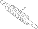
휴대용 청취 디바이스가 개시되며, 제1 및 제2 이어피스(earpiece)들; 제1 이어피스를 제2 이어피스에 결합시키는 조정가능 길이 헤드밴드 조립체로서, 내부 체적을 한정하는 하우징 컴포넌트; 및 제1 이어피스를 하우징 컴포넌트에 결합시키고 내부 체적 내로 그리고 외부로 텔레스코프(telescope)하도록 구성되는 중공 스템(hollow stem)을 포함하는, 조정가능 길이 헤드밴드 조립체; 및 제1 및 제2 이어피스들을 전기적으로 결합시키기 위해 중공 스템 및 내부 체적을 통해 연장되는 데이터 동기화 케이블을 포함하고, 데이터 동기화 케이블의 코일형 부분은 상기 중공 스템 내에 배치된다.A portable listening device is disclosed, the first and second earpieces; An adjustable length headband assembly coupling a first earpiece to a second earpiece, comprising: a housing component that defines an interior volume; And a hollow stem configured to couple the first earpiece to the housing component and telescope into and out of the interior volume; And a data synchronization cable extending through the hollow stem and internal volume to electrically couple the first and second earpieces, the coiled portion of the data synchronization cable being disposed within the hollow stem.
헤드폰이 개시되며, 제1 및 제2 이어피스들; 제1 이어피스를 제2 이어피스에 결합시키는 조정가능 길이 헤드밴드 조립체로서, 내부 체적을 한정하는 하우징 컴포넌트; 제1 이어피스를 하우징 컴포넌트에 결합시키고 내부 체적 내로 그리고 외부로 텔레스코프하도록 구성되는 중공 스템; 중공 스템의 원위 단부에 배치된 제1 안정화 요소; 하우징 컴포넌트의 원위 단부에 배치된 제2 안정화 요소를 포함하는, 조정가능 길이 헤드밴드 조립체; 및 제1 및 제2 이어피스들을 전기적으로 결합시키기 위해 중공 스템 및 내부 체적 둘 모두를 통해 연장되는 데이터 동기화 케이블을 포함한다.Headphones are disclosed, the first and second earpieces; An adjustable length headband assembly coupling a first earpiece to a second earpiece, comprising: a housing component that defines an interior volume; A hollow stem configured to couple the first earpiece to the housing component and telescope into and out of the interior volume; A first stabilizing element disposed at the distal end of the hollow stem; An adjustable length headband assembly comprising a second stabilizing element disposed at the distal end of the housing component; And a data synchronization cable extending through both the hollow stem and the interior volume to electrically couple the first and second earpieces.
휴대용 청취 디바이스가 개시되며, 이어피스로서, 이어피스 하우징; 및 이어피스 하우징 내에 배치되는 래칭 메커니즘 - 래칭 메커니즘은 애퍼처를 한정하는 래치 플레이트 및 래치 플레이트의 위치를 제1 위치로부터 제2 위치로 시프트시키도록 구성된 스위치를 가짐 - 을 포함하는 이어피스; 및 래칭 메커니즘에 의해 이어피스에 결합되는 헤드밴드 조립체를 포함하고, 헤드밴드 조립체는 헤드밴드 조립체의 제1 단부에 위치된 스템 베이스를 포함하고, 스템 베이스는 애퍼처를 통해 연장된다.A portable listening device is disclosed, the earpiece comprising: an earpiece housing; And a latching mechanism disposed within the earpiece housing, the latching mechanism having a latch plate defining an aperture and a switch configured to shift the position of the latch plate from a first position to a second position; And a headband assembly coupled to the earpiece by a latching mechanism, the headband assembly including a stem base located at the first end of the headband assembly, the stem base extending through the aperture.
이어피스가 개시되며, 스템 개구를 한정하는 이어피스 하우징; 이어피스 하우징 내에 배치된 스피커; 및 이어피스 하우징 내에 배치되는 래칭 메커니즘을 포함하고, 래칭 메커니즘은, 비대칭 애퍼처를 한정하는 래치 플레이트 및 비대칭 애퍼처의 제1 부분이 스템 개구와 정렬되는 제1 위치로부터 비대칭 애퍼처의 제2 부분이 스템 개구와 정렬되는 제2 위치로 래치 플레이트의 위치를 시프트시키도록 구성된 스위치를 갖고, 비대칭 애퍼처의 제1 부분은 제2 부분보다 작다.An earpiece is disclosed, the earpiece housing defining a stem opening; A speaker disposed in the earpiece housing; And a latching mechanism disposed within the earpiece housing, the latching mechanism comprising: a latch plate defining an asymmetric aperture and a second portion of the asymmetric aperture from a first position where the first portion of the asymmetric aperture is aligned with the stem opening. It has a switch configured to shift the position of the latch plate to a second position aligned with the stem opening, and the first part of the asymmetric aperture is smaller than the second part.
본 발명의 다른 태양들 및 이점들은 설명되는 실시예들의 원리들을 예로서 예시하는 첨부 도면들과 함께 취해지는 하기의 상세한 설명으로부터 명백하게 될 것이다.Other aspects and advantages of the invention will become apparent from the following detailed description taken in conjunction with the accompanying drawings, which illustrate by way of example the principles of the described embodiments.
개시내용은 첨부된 도면들과 함께 다음의 상세한 설명에 의해 용이하게 이해될 것이며, 도면에서, 유사한 참조 부호들은 유사한 구조적 요소들을 가리킨다.
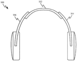
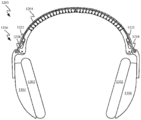
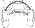
도 1a는 오버 이어(over ear) 또는 온-이어(on-ear) 헤드폰의 예시적인 세트의 정면도를 도시한다.
도 1b는 헤드밴드 조립체로부터 상이한 거리들로 연장되는 헤드폰 스템들을 도시한다.
도 2a는 동기화된 헤드폰 스템들을 갖는 헤드폰의 제1 측면의 사시도를 도시한다.
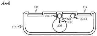
도 2b 및 도 2c는 각각 섹션 라인들(A-A 및 B-B)에 따른, 도 2a에 도시된 헤드폰의 단면도들을 도시한다.
도 2d는 도 2a에 도시된 헤드폰의 대향 측의 사시도를 도시한다.
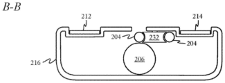
도 2e는 섹션 라인(C-C)에 따른, 도 2d에 도시된 헤드폰의 단면도를 도시한다.
도 2f 및 도 2g는 동기화된 헤드폰 스템들 및 일체형 스프링 밴드를 갖는 헤드폰의 제2 측면의 사시도들을 도시한다.
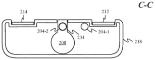
도 2h 및 도 2i는 각각 섹션 라인들(D-D 및 E-E)에 따른, 도 2f 및 도 2g에 도시된 헤드폰의 단면도들을 도시한다.
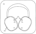
도 3a는 그의 이어피스들의 위치들의 조정을 동기화시키도록 구성된 헤드밴드 조립체를 갖는 예시적인 헤드폰을 도시한다.
도 3b는 헤드폰이 그들의 가장 큰 크기로 확장될 때의 헤드밴드 조립체의 단면도를 도시한다.
도 3c는 헤드폰이 더 작은 크기로 수축될 때의 헤드밴드 조립체의 단면도를 도시한다.
도 3d 내지 도 3f는 이어피스 위치를 동기화시키도록 구성된 헤드밴드 조립체의 사시 평면도 및 단면도를 도시한다.
도 3g 및 도 3h는 이어피스 동기화 조립체의 평면도를 도시한다.
도 3i 및 도 3j는 도 3g 및 도 3h에 도시된 것과 유사한 다른 이어피스 동기화 시스템의 평탄화된 개략도를 도시한다.
도 3k 및 도 3l은 도 3g 내지 도 3j에 도시된 이어피스 동기화 시스템들 중 어느 하나의 통합에 적합한 헤드폰(360)의 절단도들을 도시한다.
도 3m 및 도 3n은, 후퇴된 위치 및 연장된 위치에 있는 도 3g 및 도 3h에 도시된 이어피스 동기화 시스템 뿐만 아니라 데이터 동기화 케이블의 사시도들을 도시한다.
도 3o는 캐노피 구조의 일부, 및 이어피스 동기화 시스템이 캐노피 구조의 보강 부재들을 통해 어떻게 라우팅될 수 있는지를 도시한다.
도 3p 및 도 3q는 다른 대안적인 이어피스 동기화 시스템을 위한 헤드밴드 조립체의 대향 단부들에 위치된 기어 장치를 도시한다.
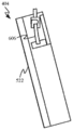
도 4a 및 도 4b는 오프-센터 피봇 이어피스들을 갖는 헤드폰의 정면도들을 도시한다.
도 5a는 비틀림 스프링들을 포함하는 예시적인 피봇 메커니즘을 도시한다.
도 5b는 이어피스의 쿠션 뒤에 위치되는 도 5a에 도시된 피봇 메커니즘을 도시한다.
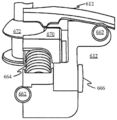
도 6a는 리프(leaf) 스프링들을 포함하는 다른 피봇 메커니즘의 사시도를 도시한다.
도 6b 내지 도 6d는 도 6a에 도시된 피봇 메커니즘을 사용하는 이어피스의 모션 범위를 도시한다.
도 6e는 도 6a에 도시된 피봇 메커니즘의 분해도를 도시한다.
도 6f는 다른 피봇 메커니즘의 사시도를 도시한다.
도 6g는 또 다른 피봇 메커니즘을 도시한다.
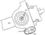
도 6h 및 도 6i는 상이한 위치들에서의 스템 베이스의 회전을 예시하기 위해 일측이 제거된 도 6g에 도시된 피봇 메커니즘을 도시한다.
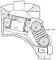
도 6j는 이어피스 하우징 내에 배치된 도 6g의 피봇 조립체의 절단 사시도를 도시한다.
도 6k 및 도 6l은 나선형 스프링들이 이완된 상태 및 압축된 상태에 있는 이어피스 하우징 내에 위치된 피봇 조립체의 부분 측단면도들을 도시한다.
도 6m 및 도 6n은 그의 피봇 조립체로부터 격리된 스템 베이스의 2개의 상이한 회전 위치들의 측면도들을 도시한다.
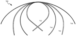
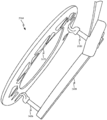
도 7a는 헤드밴드 조립체에서 사용하기에 적합한 스프링 밴드의 다수의 위치들을 도시한다.
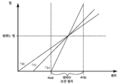
도 7b는, 도 7a에 도시된 스프링 밴드의 변위의 함수로서 스프링 레이트에 기초하여 스프링 힘이 어떻게 변하는지를 예시한 그래프를 도시한다.
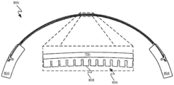
도 8a 및 도 8b는 사용자의 목 둘레를 너무 단단히 감싸는 헤드폰에 의해 야기되는 불편함을 방지하기 위한 해결책을 도시한다.
도 8c 및 도 8d는 스프링 밴드가 중립 위치로 복귀하는 것을 방지하기 위해 스프링 밴드의 하부 측을 따라 별도의 그리고 별개의 너클들이 어떻게 배열될 수 있는지를 도시한다.
도 8e 및 도 8f는 헤드밴드 조립체를 이어피스들에 결합시키는 스프링들이 헤드폰에 의해 사용자에게 인가되는 힘의 실제 양을 설정하기 위해 스프링 밴드와 어떻게 협동할 수 있는지를 도시한다.
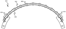
도 8g 및 도 8h는 낮은 스프링-레이트 밴드를 사용하여 한 쌍의 헤드폰의 모션 범위를 제한하는 다른 방식을 도시한다.
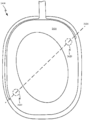
도 9a는 사용자의 귀 위에 위치된 헤드폰의 이어피스를 도시한다.
도 9b는 표면 아래에 있고 귀와 연관된 귀 윤곽들에 근접한 용량성 센서들의 위치들을 도시한다.
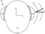
도 10a는 헤드폰을 착용한 사용자의 예시적인 머리의 평면도를 도시한다.
도 10b는 도 10a에 도시된 헤드폰의 정면도를 도시한다.
도 10c 및 도 10d는 도 10a에 도시된 헤드폰의 평면도들, 및 헤드폰의 이어피스들이 각각의 요축들(yaw axes)을 중심으로 어떻게 회전될 수 있는지를 도시한다.
도 10e 및 도 10f는 헤드밴드에 대한 이어피스들의 롤(roll) 및/또는 요(yaw)가 검출될 때 수행될 수 있는 제어 방법들을 설명하는 흐름도들을 도시한다.
도 10g는 본 명세서에 설명된 다양한 컴포넌트들을 구현하는 데 사용될 수 있는 컴퓨팅 디바이스(1070)의 시스템 레벨 블록 다이어그램을 도시한다.
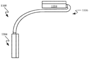
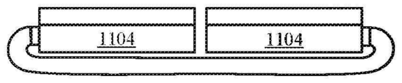
도 11a 내지 도 11c는 접이식 헤드폰을 도시한다.
도 11d 내지 도 11f는 접이식 헤드폰의 이어피스들이 변형가능 밴드 구역의 외부-대면 표면을 향해 어떻게 접혀질 수 있는지를 도시한다.
도 12a 및 도 12b는 스프링 밴드의 대향 측면들을 끌어당김으로써 아치형 상태로부터 평탄화된 상태로 전환될 수 있는 헤드폰 실시예를 도시한다.
도 12c 및 도 12d는 각각 아치형 상태 및 평탄화된 상태에 있는 접이식 스템 구역의 측면도들을 도시한다.
도 12e는 도 12d에 도시된 헤드폰의 일 단부의 측면도를 도시한다.
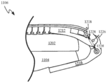
도 13a 및 도 13b는 아치형 상태와 평탄화된 상태들 사이에서 전환되기 위해 축외(off-axis) 케이블을 사용하는 헤드폰의 부분 단면도들을 도시한다.
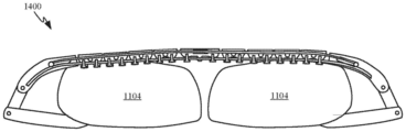
도 14a 내지 도 14c는 헤드폰의 이어피스들의 이동의 제1 부분을 통해 헤드폰의 평탄화를 지연시키는 신장 핀(elongating pin)에 의해 적어도 부분적으로 제약된 접이식 스템 구역을 갖는 헤드폰의 부분 단면도들을 도시한다.
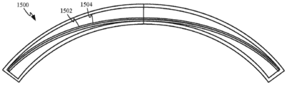
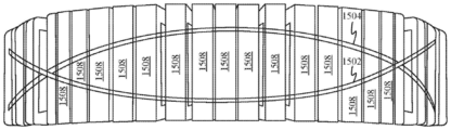
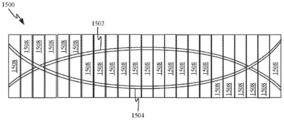
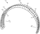
도 15a 내지 도 15f는 상이한 각도들로부터의 그리고 상이한 상태들에 있는 헤드밴드 조립체(1500)의 다양한 도면들을 도시한다.
도 16a 및 도 16b는 접혀진 상태 및 아치형 상태에 있는 헤드밴드 조립체를 도시한다.
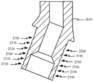
도 17 및 도 18은 다른 접이식 헤드폰 실시예의 도면들을 도시한다.
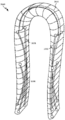
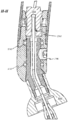
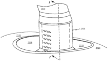
도 19는 헤드밴드 하우징의 일 측면뿐만 아니라 헤드밴드 하우징의 단부로부터 연장되는 텔레스코핑 부재를 도시한다.
도 20a는 도 20a에 도시된 헤드밴드 하우징의 측면의 분해도를 도시한다.
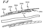
도 20b는 도 20a에 도시된 단면 라인 F-F에 따른 하부 하우징 컴포넌트의 제1 단부의 단면도를 도시한다.
도 20c는 도 20a에 도시된 단면 라인 G-G에 따른 하부 하우징 컴포넌트의 제2 단부의 단면도를 도시한다.
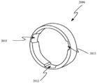
도 20d는 부싱의 내부-대면 표면 주위에서 반경방향으로 이격된 다수의 핑거 채널들을 한정하는 부싱의 사시도를 도시한다.
도 21a는 스프링 부재 및 텔레스코핑 부재의 일 단부의 사시도를 도시한다.
도 21b는 텔레스코핑 부재의 단부에 의해 한정된 개구의 제1 세트 내에 맞물린 스프링 부재의 스프링 핑거들을 도시한다.
도 21c는 스프링 핑거들이 텔레스코핑 부재의 단부에 의해 한정되는 제2 세트의 개구들 내에 맞물리도록 시프트된 스프링 부재를 도시한다.
도 21d 내지 도 21g는 텔레스코핑 조립체가 통과하여 연장되는 하부 하우징 조립체에 의해 한정된 개구에 위치된 다양한 로킹 메커니즘들을 도시한다.
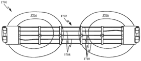
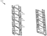
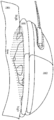
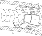
도 22a 내지 도 22e는 하부 하우징 컴포넌트 내에 배치된 동기화 케이블의 일부분에 대한 다양한 연장 및 수축된 코일 구성들을 도시한다.
도 23a는 데이터 플러그와 연관된 컴포넌트들의 분해도를 도시한다.
도 23b는 데이터 플러그를 고정식으로 위치시키기 위해 나사산 개구 내에 완전히 맞물린 나사산 체결구와 완전히 조립되는 텔레스코핑 부재를 도시한다.
도 23c는 도 23b의 섹션 라인 H-H에 따른 텔레스코핑 부재의 단면도를 도시한다.
도 23d는 데이터 플러그의 일부분의 사시도를 도시한다.
도 23e는 데이터 플러그의 일부분의 측단면도를 도시하고, 데이터 플러그의 본체의 대향 측면들 상에 위치된 다수의 접착 채널들을 도시한다.
도 23f는 스템 베이스에 접착되고 이어서 이어피스에 의해 한정된 리세스 내에 위치되는 데이터 플러그를 도시한다.
도 23g는 스템 베이스에 의해 한정된 리세스 내에 배치되고 이어서 이어피스의 리세스 내에 위치된 데이터 플러그의 단면도를 도시한다.
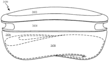
도 24a는 이어피스 및 이어패드의 사시도들을 도시한다.
도 24b는 한 쌍의 헤드폰의 이어피스들이 사용자의 편안함을 희생시키지 않고서 얇은 이어패드들을 가질 수 있는 방법을 도시한다.
도 24c는 포스트들이 이어패드를 지지하는 가요성 기판을 이어피스 요크(yoke)들에 결합시키는 방법을 도시한다.
도 24d는 이어피스, 및 이어패드가 사용자의 머리의 두측 윤곽들을 수용하도록 굽혀지게 구성된 회전축을 도시한다.
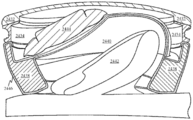
도 24e 내지 도 24g는 사용자의 머리의 두측 윤곽들을 고려하도록 설계된 구성의 다른 이어피스를 도시한다.
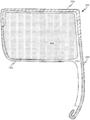
도 25a 내지 도 25c는 재료의 다수의 층들로부터 형성된 다른 이어패드 구성의 다양한 도면들을 도시한다.
도 25d는 헤드폰이 활성 사용 중일 때 텍스타일 층의 열처리된 구역들이 사용자의 머리의 측면과 직접 접촉하는 방법을 도시한다.
도 26a 및 도 26b는 상이한 배향들의 이어패드의 사시도들을 도시한다.
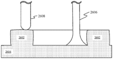
도 26c 내지 도 26g는 폼(foam)의 블록으로부터 이어패드를 형성하기 위한 다양한 제조 동작들을 도시한다.
도 27a는 앞서 기술된 이어피스들 중 많은 것에 적용될 수 있는 이어피스 내의 예시적인 음향 구성의 측단면도를 도시한다.
도 27b는 스피커 조립체와 연관된 내부 체적의 형상 및 크기를 예시하기 위해 입력 패널이 제거된 이어피스의 외부를 도시한다.
도 27c는 이어피스 내에 장착된 마이크로폰을 도시한다.
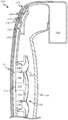
도 28은 이어피스의 외부 대면 표면을 형성할 수 있는 입력 패널을 갖는 이어피스를 도시한다.
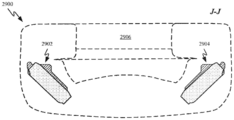
도 29a 및 도 29b는 이어피스 내의 분포된 배터리 조립체들의 위치를 예시하는 이어피스의 윤곽의 사시도 및 단면도를 도시한다.
도 29c는 2개 초과의 별개의 배터리 조립체들이 단일 이어피스 하우징 내에 통합될 수 있는 방법을 도시한다.
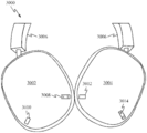
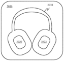
도 30a는 헤드밴드에 의해 함께 결합된 이어피스들을 포함하는 예시적인 헤드폰을 도시한다.
도 30b는 본 명세서에서 논의되는 서컴오럴(circumaural) 및 수프라-오럴(supra-aural) 헤드폰 설계들과 함께 사용하기에 매우 적합한 예시적인 운반/보관 케이스를 도시한다.
도 30c는 케이스의 리세스 내에 위치된 헤드폰(3000)을 도시한다.
도 30d는 도 30c의 섹션 라인 K-K에 따른 이어피스의 단면도를 도시한다.
도 30e는 헤드폰이 내부에 위치된 운반 케이스를 도시한다.
도 31a 및 도 31b는 기술된 헤드폰과 함께 사용하기에 적합한 조명식 버튼 조립체를 도시한다.
도 31c 및 도 31d는 각각 디바이스 하우징 내에서 비작동 및 작동 위치들에서 도 31a 및 도 31b에 도시된 조명식 버튼 조립체의 측면도들을 도시한다.
도 31e는 조명식 윈도우의 사시도를 도시한다.
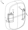
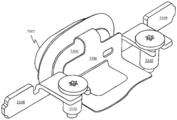
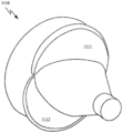
도 32a 및 도 32b는 헤드폰 밴드의 스템 베이스에 의해 맞물린 제거가능 이어피스와 연관된 피봇 조립체의 사시도들을 도시한다.
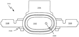
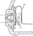
도 33a 내지 도 33c는 피봇 조립체의 래칭 메커니즘의 상이한 도면들을 도시한다.
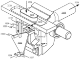
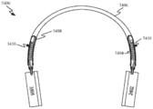
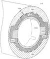
도 34a는 헤드밴드 조립체에 의해 기계적으로 함께 결합된 이어피스들을 포함하는 헤드폰을 도시한다.
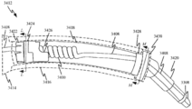
도 34b는 헤드밴드 조립체의 스템 구역의 확대도를 도시한다.
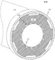
도 34c는 텔레스코핑 컴포넌트의 원위 단부의 확대도를 도시한다.
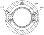
도 34d는 도 34b에 도시된 바와 같은 단면 라인 L-L에 따른 텔레스코핑 컴포넌트의 원위 단부의 단면도를 도시한다.
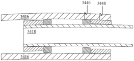
도 34e는 도 34b에 도시된 바와 같은 단면 라인 M-M에 따른 하부 하우징 컴포넌트의 원위 단부의 단면도를 도시한다.
도 34f 내지 도 34h는 하부 하우징 컴포넌트와 텔레스코핑 컴포넌트 사이에 더 많거나 더 적은 양의 플레이가 확립되게 하는 다수의 대안적인 실시예들을 도시한다.
도 34i 및 도 34j는 하부 하우징 컴포넌트에 의해 한정되는 내부 체적 내에 배치되는 텔레스코핑 컴포넌트를 포함하는 구성들을 도시한다.The disclosure will be readily understood by the following detailed description in conjunction with the accompanying drawings, in which like reference numerals indicate similar structural elements.
1A shows a front view of an exemplary set of over ear or on-ear headphones.
1B shows headphone stems extending at different distances from the headband assembly.
2A shows a perspective view of a first side of a headphone with synchronized headphone stems.
2B and 2C show cross-sectional views of the headphone shown in FIG. 2A, respectively, along section lines AA and BB.
2D shows a perspective view of the headphone shown in FIG. 2A on the opposite side.
FIG. 2E shows a cross-sectional view of the headphone shown in FIG. 2D according to section line CC.
2F and 2G show perspective views of a second side of a headphone with synchronized headphone stems and an integral spring band.
2H and 2I show cross-sectional views of the headphones shown in FIGS. 2F and 2G, respectively, along section lines DD and EE.
3A shows an exemplary headphone with a headband assembly configured to synchronize the adjustment of the positions of its earpieces.
3B shows a cross-sectional view of the headband assembly when the headphones are expanded to their largest size.
3C shows a cross-sectional view of the headband assembly when the headphones are retracted to a smaller size.
3D-3F show perspective top and cross-sectional views of a headband assembly configured to synchronize earpiece positions.
3G and 3H show top views of the earpiece synchronization assembly.
3I and 3J show a flattened schematic view of another earpiece synchronization system similar to that shown in FIGS. 3G and 3H.
3K and 3L show cut-away views of
3M and 3N show perspective views of the data synchronization cable as well as the earpiece synchronization system shown in FIGS. 3G and 3H in the retracted and extended positions.
3O shows a part of the canopy structure, and how the earpiece synchronization system can be routed through the reinforcement members of the canopy structure.
3p and 3q show gear arrangements located at opposite ends of the headband assembly for another alternative earpiece synchronization system.
4A and 4B show front views of a headphone with off-center pivot earpieces.
5A shows an exemplary pivot mechanism including torsion springs.
5b shows the pivot mechanism shown in FIG. 5a located behind the earpiece cushion.
6A shows a perspective view of another pivot mechanism including leaf springs.
6B-6D show the motion range of the earpiece using the pivot mechanism shown in FIG. 6A.
FIG. 6E shows an exploded view of the pivot mechanism shown in FIG. 6A.
6F shows a perspective view of another pivot mechanism.
6G shows another pivot mechanism.
6H and 6I show the pivot mechanism shown in FIG. 6G with one side removed to illustrate the rotation of the stem base in different positions.
6J shows a cut perspective view of the pivot assembly of FIG. 6G disposed within the earpiece housing.
6K and 6L show partial cross-sectional side views of the pivot assembly positioned within the earpiece housing with the helical springs in a relaxed and compressed state.
6M and 6N show side views of two different rotational positions of the stem base isolated from its pivot assembly.
7A shows multiple positions of a spring band suitable for use in a headband assembly.
7B shows a graph illustrating how the spring force changes based on the spring rate as a function of the displacement of the spring band shown in FIG. 7A.
8A and 8B show solutions to prevent discomfort caused by headphones that wrap around the neck of the user too tightly.
8C and 8D show how separate and separate knuckles can be arranged along the lower side of the spring band to prevent the spring band from returning to the neutral position.
8E and 8F show how the springs coupling the headband assembly to the earpieces can cooperate with the spring band to establish the actual amount of force applied to the user by the headphones.
8G and 8H show another way to limit the motion range of a pair of headphones using a low spring-rate band.
9A shows the earpiece of a headphone positioned over the user's ear.
9B shows locations of capacitive sensors below the surface and close to ear contours associated with the ear.
10A shows a top view of an exemplary head of a user wearing headphones.
10B shows a front view of the headphones shown in FIG. 10A.
10C and 10D show top views of the headphones shown in FIG. 10A, and how the earpieces of the headphones can be rotated around their respective yaw axes.
10E and 10F show flow charts illustrating control methods that can be performed when a roll and/or yaw of earpieces for a headband is detected.
10G shows a system level block diagram of a
11A-11C show foldable headphones.
11D-11F show how the earpieces of the foldable headphones can be folded towards the outer-facing surface of the deformable band zone.
12A and 12B show a headphone embodiment that can be switched from an arcuate state to a flattened state by pulling opposite sides of the spring band.
12C and 12D show side views of the foldable stem area in an arcuate and flattened state, respectively.
12E shows a side view of one end of the headphone shown in FIG. 12D.
13A and 13B show partial cross-sectional views of a headphone using an off-axis cable to switch between the arcuate and flattened states.
14A-14C show partial cross-sectional views of a headphone with a foldable stem region at least partially constrained by an elongating pin that delays flattening of the headphone through the first portion of the movement of the earpieces of the headphone.
15A-15F show various views of the
16A and 16B show the headband assembly in a folded state and an arcuate state.
17 and 18 show views of another foldable headphone embodiment.
19 shows a telescoping member extending from one end of the headband housing as well as from the end of the headband housing.
20A shows an exploded view of the side of the headband housing shown in FIG. 20A.
20B shows a cross-sectional view of the first end of the lower housing component along the section line FF shown in FIG. 20A.
20C shows a cross-sectional view of the second end of the lower housing component along the section line GG shown in FIG. 20A.
20D shows a perspective view of a bushing defining multiple finger channels radially spaced around the inner-facing surface of the bushing.
21A shows a perspective view of one end of a spring member and a telescoping member.
21B shows spring fingers of a spring member engaged within a first set of openings defined by the ends of the telescoping member.
21C shows the spring member shifted so that the spring fingers engage within a second set of openings defined by the end of the telescoping member.
21D-21G show various locking mechanisms located in the opening defined by the lower housing assembly through which the telescoping assembly extends.
22A-22E show various extended and retracted coil configurations for a portion of the synchronization cable disposed within the lower housing component.
23A shows an exploded view of components associated with a data plug.
23B shows the telescoping member fully assembled with the threaded fastener fully engaged within the threaded opening to securely position the data plug.
23C shows a cross-sectional view of the telescoping member along section line HH of FIG. 23B.
23D shows a perspective view of a portion of a data plug.
23E shows a cross-sectional side view of a portion of a data plug, and shows multiple adhesive channels located on opposite sides of the body of the data plug.
23F shows the data plug attached to the stem base and then positioned within the recess defined by the earpiece.
23G shows a cross-sectional view of the data plug disposed within the recess defined by the stem base and then positioned within the recess of the earpiece.
24A shows perspective views of the earpiece and earpads.
24B shows how the earpieces of a pair of headphones can have thin earpads without sacrificing user comfort.
24C shows how the posts couple the flexible substrate supporting the earpads to the earpiece yokes.
FIG. 24D shows the earpiece, and a rotating shaft configured such that the earpads are bent to accommodate the two contours of the user's head.
24E-24G show another earpiece in a configuration designed to take into account the two contours of the user's head.
25A-25C show various views of different earpad configurations formed from multiple layers of material.
25D shows how the heat treated regions of the textile layer directly contact the side of the user's head when the headphones are in active use.
26A and 26B show perspective views of ear pads of different orientations.
26C-26G show various manufacturing operations for forming an ear pad from a block of foam.
27A shows a cross-sectional side view of an exemplary acoustic configuration within the earpiece that can be applied to many of the earpieces described above.
27B shows the exterior of the earpiece with the input panel removed to illustrate the shape and size of the interior volume associated with the speaker assembly.
27C shows a microphone mounted within the earpiece.
28 shows an earpiece with an input panel capable of forming the outer facing surface of the earpiece.
29A and 29B show perspective and cross-sectional views of the contour of an earpiece illustrating the location of distributed battery assemblies within the earpiece.
29C shows how more than two separate battery assemblies can be integrated into a single earpiece housing.
30A shows an exemplary headphone comprising earpieces joined together by a headband.
30B shows an exemplary carrying/storage case very suitable for use with the circumaural and supra-aural headphone designs discussed herein.
30C shows
30D shows a cross-sectional view of the earpiece along section line KK of FIG. 30C.
30E shows the carrying case in which the headphones are located.
31A and 31B show illuminated button assemblies suitable for use with the described headphones.
31C and 31D show side views of the illuminated button assembly shown in FIGS. 31A and 31B, respectively, in non-operating and operating positions within the device housing.
31E shows a perspective view of an illuminated window.
32A and 32B show perspective views of the pivot assembly associated with the removable earpiece engaged by the stem base of the headphone band.
33A-33C show different views of the latching mechanism of the pivot assembly.
34A shows headphones comprising earpieces mechanically joined together by a headband assembly.
34B shows an enlarged view of the stem region of the headband assembly.
34C shows an enlarged view of the distal end of the telescoping component.
FIG. 34D shows a cross-sectional view of the distal end of the telescoping component along section line LL as shown in FIG. 34B.
34E shows a cross-sectional view of the distal end of the lower housing component along section line MM as shown in FIG. 34B.
34F-34H show a number of alternative embodiments that allow more or less play to be established between the lower housing component and the telescoping component.
34I and 34J show configurations including a telescoping component disposed within an interior volume defined by a lower housing component.
본 출원에 따른 방법들 및 장치의 대표적인 응용예들이 이 섹션에 설명된다. 이 예들은 단지 맥락을 부가하고 설명된 실시예들의 이해에 도움을 주기 위해 제공되어 있다. 따라서, 설명된 실시예들이 이들의 구체적인 상세한 설명의 일부 또는 전부 없이도 실시될 수 있다는 것이 본 기술 분야의 통상의 기술자에게 명백할 것이다. 다른 경우들에서, 잘 알려진 공정 단계들은 설명된 실시예들을 불필요하게 불명료하게 하지 않기 위해 상세히 설명되지 않았다. 다른 응용예들도 가능하며, 따라서 이하의 예들은 제한하는 것으로 취해져서는 안 된다.Representative applications of the methods and apparatus according to the present application are described in this section. These examples are provided merely to add context and to help understand the described embodiments. Accordingly, it will be apparent to those skilled in the art that the described embodiments may be practiced without some or all of their specific detailed description. In other instances, well-known process steps have not been described in detail in order not to unnecessarily obscure the described embodiments. Other applications are possible, and therefore the following examples should not be taken as limiting.
하기의 상세한 설명에서는, 설명의 일부를 형성하고 기술된 실시예들에 따른 특정 실시예들이 예시로서 도시되어 있는 첨부 도면들이 참조된다. 이러한 실시예들은 본 기술 분야의 통상의 기술자가 설명된 실시예들을 실행할 수 있게 하도록 충분히 상세하게 설명되지만, 이러한 예들은 제한하는 것이 아니어서, 다른 실시예들이 사용될 수 있으며 설명된 실시예들의 기술적 사상 및 범주를 벗어남이 없이 변경이 이루어질 수 있음이 이해된다.In the following detailed description, reference is made to the accompanying drawings, which form a part of the description and in which specific embodiments according to the described embodiments are illustrated as examples. Although these embodiments are described in sufficient detail to enable those skilled in the art to implement the described embodiments, these examples are not limiting, and other embodiments may be used and the technical spirit of the described embodiments And it is understood that changes may be made without departing from the scope.
헤드폰은 수년 동안 생산되어 왔지만, 수많은 설계 문제점들이 남아 있다. 예를 들어, 헤드폰과 연관된 헤드밴드들의 기능은 일반적으로 사용자의 귀들 위에 헤드폰의 이어피스들을 유지하고 이어피스들 사이에 전기적 연결을 제공하는 것으로만 기능하는 기계적 연결로 제한되어 왔다. 더욱이, 증강된 현실 및 가상 현실 헤드셋과 같은 다른 유형들의 휴대용 청취 디바이스 내로의 헤드폰의 통합은 또한 헤드폰을 새로운 개선된 폼 팩터에 적응시키기 위한 불편함으로 인해 느려졌다. 헤드밴드는 헤드폰의 부피에 실질적으로 부가되는 경향이 있으며, 그에 의해 헤드폰의 보관이 문제가 된다. 사용자의 귀들에 대한 이어피스들의 배향의 조정을 수용하도록 설계된, 헤드밴드를 이어피스들에 연결시키는 스템들이 또한 헤드폰에 부피를 부가한다. 헤드밴드의 신장을 수용하는, 헤드밴드를 이어피스들에 연결시키는 스템들은 일반적으로 헤드밴드의 중심 부분이 사용자의 머리의 일측으로 시프트되게 허용한다. 이러한 시프트된 구성은 다소 이상하게 보여질 수 있으며, 또한, 헤드폰의 설계에 의존하여 헤드폰을 착용하기에 덜 편안하게 만들 수 있다.Headphones have been in production for many years, but a number of design problems remain. For example, the functionality of headbands associated with headphones has been limited to mechanical connections that generally only function to hold the earpieces of the headphones over the ears of the user and provide electrical connections between the earpieces. Moreover, the integration of headphones into other types of portable listening devices such as augmented reality and virtual reality headsets has also slowed due to the inconvenience of adapting the headphones to a new improved form factor. Headbands tend to be substantially added to the volume of the headphones, whereby storage of the headphones becomes a problem. Designed to accommodate adjustment of the orientation of the earpieces relative to the user's ears, the stems connecting the headband to the earpieces also add volume to the headphones. Stems that connect the headband to the earpieces, which accommodate the extension of the headband, generally allow the central portion of the headband to be shifted to one side of the user's head. This shifted configuration may look somewhat odd, and also rely on the design of the headphones to make the headphones less comfortable to wear.
헤드폰으로의 미디어 콘텐츠의 무선 전달과 같은 일부 개선들이 코드 엉킴의 문제를 완화시켰지만, 이러한 유형의 기술은 그 자신의 일괄 문제점을 도입한다. 예를 들어, 무선 헤드폰이 동작하기 위해 배터리 전력을 요구하기 때문에, 무선 헤드폰을 켜진 상태로 유지하는 사용자는 의도하지 않게 무선 헤드폰의 배터리를 고갈시켜, 새로운 배터리가 설치될 수 있을 때까지 또는 디바이스가 재충전되는 동안 헤드폰을 사용할 수 없게 만들 수 있다. 많은 헤드폰에 대한 다른 설계 문제점은, 좌측 오디오 채널이 우측 귀에 제시되고 우측 오디오 채널이 좌측 귀에 제시되는 상황을 방지하기 위해 어느 이어피스가 어느 귀에 대응하는지를 사용자가 일반적으로 알아내야 한다는 것이다.Some improvements, such as wireless delivery of media content to headphones, alleviate the problem of code tangles, but this type of technology introduces its own bulk problem. For example, because the wireless headphones require battery power to operate, a user who keeps the wireless headphones on unintentionally depletes the battery of the wireless headphones, until a new battery can be installed or the device You can make your headphones unusable while recharging. Another design problem with many headphones is that the user generally needs to find out which earpiece corresponds to which ear in order to avoid situations where the left audio channel is presented to the right ear and the right audio channel is presented to the left ear.
이어피스들의 비동기화된 위치설정에 대한 해결책은, 이어피스들과 헤드밴드의 각각의 단부들 사이의 거리를 동기화시키는 헤드밴드 내에 배치된 기계적 메커니즘의 형태를 취하는 이어피스 동기화 컴포넌트를 통합하는 것이다. 이러한 유형의 동기화는 다수의 방식들로 수행될 수 있다. 일부 실시예들에서, 이어피스 동기화 컴포넌트는 이어피스들의 움직임을 동기화시키도록 구성될 수 있는 둘 모두의 스템들 사이에서 연장되는 케이블일 수 있다. 헤드밴드로부터 멀어지는 하나의 이어피스의 모션이 다른 이어피스로 하여금 헤드밴드의 대향 단부로부터 동일한 거리로 멀어지게 이동하게 하도록 루프의 상이한 측면들이 이어피스들의 각각의 스템들에 부착되는 루프에 케이블이 배열될 수 있다. 유사하게, 하나의 이어피스를 헤드밴드의 일측을 향해 밀어내는 것은 다른 이어피스를 헤드밴드의 대향측을 향해 동일한 거리로 병진이동시킨다. 일부 실시예들에서, 이어피스 동기화 컴포넌트는, 이어피스들을 동기화되게 유지하기 위해 각각의 스템의 치형부(teeth)와 맞물리도록 구성될 수 있는 헤드밴드 내에 임베딩된 회전 기어일 수 있다.The solution to the asynchronous positioning of the earpieces is to incorporate an earpiece synchronization component that takes the form of a mechanical mechanism disposed within the headband that synchronizes the distance between the earpieces and the respective ends of the headband. This type of synchronization can be performed in a number of ways. In some embodiments, the earpiece synchronization component can be a cable extending between both stems that can be configured to synchronize the movement of the earpieces. Cables are arranged in a loop where different sides of the loop are attached to respective stems of the earpieces so that the motion of one earpiece away from the headband moves the other earpiece away from the opposite end of the headband by the same distance Can be. Similarly, pushing one earpiece towards one side of the headband translates the other earpiece towards the opposite side of the headband at the same distance. In some embodiments, the earpiece synchronization component can be a rotating gear embedded within a headband that can be configured to engage the teeth of each stem to keep the earpieces synchronized.
헤드폰 스템들과 이어피스들 사이의 종래의 부피가 큰 연결들에 대한 하나의 해결책은 밴드에 대한 이어피스의 모션을 제어하기 위해 스프링-구동식 피봇 메커니즘을 사용하는 것이다. 스프링-구동식 피봇 메커니즘은 이어피스의 최상부 부근에 위치되어, 그 메커니즘이 이어피스 외부에 있는 대신에 이어피스 내에 통합되게 허용할 수 있다. 이러한 방식으로, 피봇 기능은 헤드폰의 전체 부피에 부가되지 않으면서 이어피스들 내에 구축될 수 있다. 상이한 유형들의 스프링들이 헤드밴드에 대한 이어피스들의 모션을 제어하는 데 이용될 수 있다. 비틀림 스프링들 및 리프 스프링들을 포함하는 특정 예들이 하기에 상세히 설명된다. 각각의 이어피스와 연관된 스프링들은 헤드폰을 착용한 사용자에게 가해지는 힘의 양을 설정하기 위해 헤드밴드 내의 스프링들과 협동할 수 있다. 일부 실시예들에서, 헤드밴드 내의 스프링들은 상이한 머리 크기들을 갖는 큰 범위의 사용자에 걸쳐 가해지는 힘 변동을 최소화시키도록 구성된 낮은 스프링-레이트 스프링들일 수 있다. 일부 실시예들에서, 헤드밴드 내에서의 낮은-레이트 스프링들의 이동은 헤드밴드가 목 둘레에 착용될 때 사용자의 목 주위에 단단히 클램핑되는 것을 방지하도록 제한될 수 있다.One solution to conventional bulky connections between headphone stems and earpieces is to use a spring-driven pivot mechanism to control the motion of the earpiece relative to the band. The spring-driven pivot mechanism is located near the top of the earpiece, allowing the mechanism to be integrated into the earpiece instead of outside the earpiece. In this way, the pivot function can be built into the earpieces without adding to the overall volume of the headphones. Different types of springs can be used to control the motion of the earpieces relative to the headband. Specific examples including torsion springs and leaf springs are described in detail below. The springs associated with each earpiece can cooperate with the springs in the headband to set the amount of force applied to the user wearing the headphones. In some embodiments, the springs in the headband can be low spring-rate springs configured to minimize force variations applied across a large range of users with different head sizes. In some embodiments, movement of low-rate springs within the headband may be limited to prevent the headband from being clamped tightly around the user's neck when worn around the neck.
대형 헤드밴드 폼 팩터 문제점에 대한 하나의 해결책은 이어피스들에 대해 평탄화되도록 헤드밴드를 설계하는 것이다. 평탄화 헤드밴드는 헤드밴드의 아치형의 기하학적 구조가 평평한 기하학적 구조로 소형화되게 허용하여, 헤드폰이 더 편리한 보관 및 운송에 적합한 크기 및 형상을 달성하게 허용한다. 이어피스들은, 이어피스들이 헤드밴드의 중심을 향해 접히게 허용하는 접이식 스템 구역에 의해 헤드밴드에 부착될 수 있다. 헤드밴드를 향해 각각의 이어피스를 접기 위해 인가되는 힘은 헤드밴드의 대응하는 단부를 끌어당겨 헤드밴드를 평탄화시키는 메커니즘으로 전달된다. 일부 실시예들에서, 스템은, 헤드폰을 다시 아치형 상태로 전환시키기 위한 해제 버튼의 부가를 요구하지 않으면서 헤드폰의 아치형 상태로의 의도하지 않은 복귀를 방지하는 오버센터 로킹 메커니즘을 포함할 수 있다.One solution to the large headband form factor problem is to design the headband to flatten against the earpieces. The flattened headband allows the arched geometry of the headband to be downsized to a flattened geometry, allowing headphones to achieve a size and shape suitable for more convenient storage and transportation. The earpieces can be attached to the headband by a foldable stem region that allows the earpieces to fold towards the center of the headband. The force applied to fold each earpiece towards the headband is transmitted to a mechanism that flattens the headband by pulling the corresponding end of the headband. In some embodiments, the stem may include an overcenter locking mechanism that prevents unintentional return of the headphones to the arched state without requiring the addition of a release button to return the headphones to the arched state again.
무선 헤드폰과 연관된 전력 관리 문제점들에 대한 해결책은, 밴드에 대한 이어피스들의 배향을 모니터링하도록 구성될 수 있는 배향 센서를 이어피스들 내에 통합하는 것을 포함한다. 밴드에 대한 이어피스들의 배향은 헤드폰이 사용자의 귀들 위에 착용되고 있는지 여부를 결정하는 데 사용될 수 있다. 이어서, 이러한 정보는, 헤드폰이 사용자의 귀들 위에 위치되는 것으로 결정되지 않을 때 헤드폰을 대기 모드에 두거나 헤드폰을 전체적으로 끄기 위해 사용될 수 있다. 일부 실시예들에서, 이어피스 배향 센서들은 또한, 이어피스들이 현재 사용자의 어느 귀들을 덮고 있는지를 결정하는 데 이용될 수 있다. 헤드폰 내의 회로는, 어느 이어피스가 사용자의 어느 귀 상에 있는지에 대한 결정과 매칭하기 위해 각각의 이어피스로 라우팅된 오디오 채널들을 스위칭하도록 구성될 수 있다.A solution to power management problems associated with wireless headphones includes integrating within the earpieces an orientation sensor that can be configured to monitor the orientation of the earpieces relative to the band. The orientation of the earpieces relative to the band can be used to determine whether or not headphones are being worn over the user's ears. This information can then be used to put the headphones into standby mode or to turn off the headphones as a whole when it is not determined that the headphones are placed over the ears of the user. In some embodiments, earpiece orientation sensors may also be used to determine which ears of the user the earpieces are currently covering. The circuitry in the headphones can be configured to switch audio channels routed to each earpiece to match the decision as to which earpiece is on which ear of the user.
이들 및 다른 실시예들은 도 1 내지 도 31e를 참조하여 아래에서 논의된다. 그러나, 본 기술 분야의 통상의 기술자들은 이러한 도면들에 대하여 본 명세서에서 제공되는 상세한 설명이 단지 설명의 목적을 위한 것일 뿐이며, 제한적인 것으로 해석되지 않아야 한다는 것을 쉽게 인식할 것이다.These and other embodiments are discussed below with reference to FIGS. 1-31E. However, those skilled in the art will readily appreciate that the detailed description provided herein for these drawings is for purposes of illustration only and should not be construed as limiting.
대칭 텔레스코핑 이어피스들Symmetric telescoping earpieces
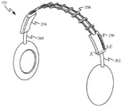
도 1a는 오버 이어 또는 온-이어 헤드폰(100)의 예시적인 세트의 정면도를 도시한다. 헤드폰(100)은 헤드폰(100)의 크기의 조정능력을 허용하기 위해 스템들(104, 106)과 상호작용하는 밴드(102)를 포함한다. 특히, 스템들(104, 106)은 다수의 상이한 머리 크기들을 수용하기 위하여 밴드(102)에 대해 독립적으로 시프트하도록 구성된다. 이러한 방식으로, 이어피스들(108, 110)의 위치는 이어피스들(108, 110)을 사용자의 귀들 바로 위에 위치시키도록 조정될 수 있다. 유감스럽게도, 도 1b에서 볼 수 있는 바와 같이, 이러한 유형의 구성은 스템들(104, 106)이 밴드(102)에 대해 미스매칭(mismatch)되게 허용한다. 도 1b에 도시된 구성은 사용자에게 덜 편안할 수 있고, 부가적으로 장식용 매력이 부족할 수 있다. 이들 문제들을 해결하기 위해, 사용자는 바람직한 외관 및 편안한 맞춤을 달성하기 위하여 밴드(102)에 대해 스템들(104, 106)을 수동으로 조정하도록 강제될 것이다. 도 1a 및 도 1b는 또한, 이어피스들(108)이 사용자의 머리의 곡률을 수용하도록 회전되게 허용하기 위해 스템들(104, 106)이 이어피스들(108)의 중심 부분으로 어떻게 아래로 연장되는지를 도시한다. 위에서 언급된 바와 같이, 이어피스들(108) 둘레에서 아래로 연장되는 스템들(104, 106)의 부분들은 이어피스들(108)의 직경들을 증가시킨다.1A shows a front view of an exemplary set of over ear or on-
도 2a는 도 1a 및 도 1b에 도시된 문제점들을 해결하도록 구성된 헤드밴드(202)를 갖는 헤드폰(200)의 사시도를 도시한다. 헤드밴드(202)는 내부 특징부들을 드러내기 위해 장식용 덮개 없이 도시된다. 특히, 헤드밴드(202)는 스템들(206, 208)의 움직임을 동기화시키도록 구성된 와이어 루프(204)를 포함할 수 있다. 와이어 가이드들(210)은 리프 스프링들(212, 214)의 곡률과 매칭하는 와이어 루프(204)의 곡률을 유지하도록 구성될 수 있다. 리프 스프링들(212, 214)은 헤드밴드(202)의 형상을 한정하고 사용자의 머리에 힘을 가하도록 구성될 수 있다. 와이어 가이드들(210) 각각은 와이어 루프(204)의 대향 측면들 및 리프 스프링들(212, 214)이 통과할 수 있는 개구들을 포함할 수 있다. 일부 실시예들에서, 와이어 루프(204)에 대한 개구들은 현저한 마찰이 개구들을 통한 와이어 루프(204)의 모션을 방해하는 것을 방지하도록 저마찰 베어링들에 의해 한정될 수 있다. 이러한 방식으로, 와이어 가이드들(210)은 와이어 루프(204)가 스템 하우징들(216, 218) 사이에서 연장되게 하는 경로를 한정한다. 와이어 루프(204)는 스템(206) 및 스템(208) 둘 모두에 커플링되며, 이어피스(126)와 스템 하우징(118) 사이의 거리(124)와 실질적으로 동일하게 이어피스(122)와 스템 하우징(116) 사이의 거리(120)를 유지하도록 기능한다. 와이어 루프(204)의 제1 측면(204-1)은 스템(206)에 커플링되고, 와이어 루프(204)의 제2 측면(204-2)은 스템(208)에 커플링된다. 와이어 루프의 대향 측면들이 스템들(206, 208)에 부착되기 때문에, 스템들 중 하나의 스템의 움직임은 동일한 방향으로의 다른 스템의 움직임을 초래한다.2A shows a perspective view of a
도 2b는 섹션 라인(A-A)에 따른 스템 하우징(116)의 일부의 단면도를 도시한다. 특히, 도 2b는 스템(206)의 돌출부(228)가 와이어 루프(204)의 일부와 어떻게 맞물리는지를 도시한다. 스템(206)의 돌출부(228)가 와이어 루프(204)와 커플링되기 때문에, 헤드폰(100)의 사용자가 이어피스(222)를 스템 하우징(216)으로부터 더 멀어지게 끌어당길 때, 와이어 루프(204)가 또한 끌어당겨져서, 와이어 루프(204)로 하여금 헤드밴드(202)를 통해 순환하게 한다. 헤드밴드(202)를 통한 와이어 루프(204)의 순환은 스템(208)의 돌출부에 의해 와이어 루프(204)에 유사하게 커플링되는 이어피스들(226)의 위치를 조정한다. 와이어 루프(204)와의 기계적 커플링을 형성하는 것에 부가하여, 돌출부(228)는 또한 와이어 루프(204)에 전기적으로 커플링될 수 있다. 일부 실시예들에서, 돌출부(228)는 와이어 루프(204)를 이어피스(222) 내의 전기 컴포넌트들에 전기적으로 커플링시키는 전기 전도성 경로(230)를 포함할 수 있다. 일부 실시예들에서, 와이어 루프(204)는 전기 전도성 재료로부터 형성될 수 있어서, 신호들이 와이어 루프(204)에 의해 이어피스들(222, 226) 내의 컴포넌트들 사이에서 전달될 수 있게 한다.2B shows a cross-sectional view of a portion of the stem housing 116 along section line A-A. In particular, FIG. 2B shows how the
도 2c는 섹션 라인(B-B)에 따른 스템 하우징(116)의 다른 단면도를 도시한다. 특히, 도 2c는 와이어 루프(204)가 스템 하우징(216) 내에서 풀리(232)와 어떻게 맞물리는지를 도시한다. 풀리(232)는 스템 하우징(216)으로부터 더 가깝거나 더 멀어지는 이어피스(222)의 움직임에 의해 생성되는 임의의 마찰을 최소화시킨다. 대안적으로, 와이어 루프(204)는 스템 하우징(216) 내의 정적 베어링을 통해 라우팅될 수 있다.2C shows another cross-sectional view of the stem housing 116 along section line B-B. In particular, FIG. 2C shows how the
도 2d는 헤드폰(200)의 다른 사시도를 도시한다. 이러한 도면에서, 와이어 루프(204)의 제1 측면(204-1) 및 제2 측면(204-2)이 헤드밴드(202)의 일측으로부터 다른 측으로 교차함에 따라 그들이 측방향으로 시프트된다는 것을 알 수 있다. 이는 도 2e에 도시된 바와 같이, 측면들(204-1, 204-2)이 스템 하우징(218)에 도달할 때까지, 제2 측면(204-2)이 스템(208)과 중심설정 및 정렬되도록, 와이어 가이드들(210)에 의해 한정되는 개구들이 점진적으로 오프셋됨으로써 달성될 수 있다.2D shows another perspective view of the
도 2e는 제2 측면(204-2)이 돌출부(234)에 의해 어떻게 맞물리는지를 도시한다. 스템들(206, 208)이 와이어 루프(204)의 각각의 제1 측면 및 제2 측면에 부착되기 때문에, 이어피스(226)를 스템 하우징(218)을 향해 밀어내는 것은 또한 이어피스(222)가 스템 하우징(216)을 향해 밀리게 되는 것을 초래한다. 도 2a 내지 도 2e에 도시된 구성의 다른 이점은 스템들(206, 208)의 이동 방향에 관계없이, 와이어 루프(204)가 항상 인장 상태(tension)로 유지된다는 것이다. 이는 이어피스들(222, 226)을 연장시키거나 후퇴시키는 데 필요한 힘의 양을 방향에 관계없이 일관되게 유지한다.2E shows how the second side 204-2 is engaged by the
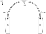
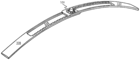
도 2f 및 도 2g는 헤드폰(250)의 사시도들을 도시한다. 헤드폰(250)은 단지 단일 리프 스프링(252)만이 스템 하우징(254)을 스템 하우징(256)에 연결시키는 데 사용되는 것을 제외하고는 헤드폰(200)과 유사하다. 이러한 실시예에서, 와이어 루프(258)는 리프 스프링(252)의 양측에 위치될 수 있다. 와이어 루프(258)의 일측 바로 아래에 위치되는 대신에, 스템들(260, 262)은 와이어 루프(258)의 2개의 측면들 사이에 직접 위치될 수 있고, 스템들(260, 262)의 아암(arm)에 의해 와이어 루프(258)의 일측에 연결될 수 있다.2F and 2G show perspective views of
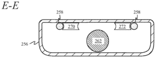
도 2h 및 도 2i는 스템 하우징들(254, 256)의 내부 부분의 단면도들을 도시한다. 도 2h는 섹션 라인(D-D)에 따른 스템 하우징(254)의 단면도를 도시한다. 도 2h는 스템(260)이 와이어 루프(258)와 맞물리는 측방향 돌출 아암(268)을 어떻게 포함할 수 있는지를 도시한다. 이러한 방식으로, 측방향 돌출 아암(268)은 스템(260)을 와이어 루프(258)에 커플링시켜, 이어피스(264)가 이동될 때 이어피스(266)가 동등한 위치로 유지되게 한다. 도 2i는 섹션 라인(E-E)에 따른 스템 하우징(256)의 단면도를 도시한다. 도 2i는 또한 와이어 루프(258)가 풀리들(270, 272)에 의해 스템 하우징(256) 내에서 어떻게 라우팅될 수 있는지를 도시한다. 와이어 루프(258)를 스템(262) 위로 라우팅함으로써, 와이어 루프(258)와 스템(206) 사이의 임의의 간섭이 회피될 수 있다.2H and 2I show cross-sectional views of the inner portion of the
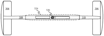
도 3a 내지 도 3c는 도 1a 및 도 1b에 설명된 문제점들을 해결하도록 구성된 다른 헤드폰 실시예를 도시한다. 도 3a는 헤드밴드 조립체(302)를 포함하는 헤드폰(300)을 도시한다. 헤드밴드 조립체(302)는 스템들(308, 310)에 의해 이어피스들(304, 306)에 결합된다. 헤드밴드 조립체(302)의 크기 및 형상은 헤드폰(300)에 대해 얼마나 많은 조정능력이 바람직하는지에 의존하여 변할 수 있다.3A-3C show another headphone embodiment configured to solve the problems described in FIGS. 1A and 1B. 3A shows a
도 3b는 헤드폰(300)이 그들의 최대 크기로 확장될 때의 헤드밴드 조립체(302)의 단면도를 도시한다. 특히, 도 3b는 헤드밴드 조립체(302)가 스템들(308, 310) 각각의 단부들에 의해 한정되는 치형부와 맞물리도록 구성된 기어(312)를 어떻게 포함하는지를 도시한다. 일부 실시예들에서, 스템들(308, 310)은, 스템들(308, 310)에 의해 한정되는 개구들과 맞물림으로써 스프링 핀들(314, 316)에 의해 헤드밴드 조립체(302) 밖으로 완전히 끌어당겨지는 것이 방지될 수 있다.3B shows a cross-sectional view of the
도 3c는 헤드폰(300)이 더 작은 크기로 수축될 때의 헤드밴드 조립체(302)의 단면도를 도시한다. 특히, 도 3c는, 스템(308) 또는 스템(310)의 임의의 움직임이 기어(312)에 의해 다른 스템으로 병진이동되는 것으로 인해 기어(312)가 스템들(308, 310)의 위치를 어떻게 동기화되게 유지하는지를 도시한다. 일부 실시예들에서, 헤드밴드 조립체(302)의 외부를 한정하는 하우징의 강성은 더 일관된 느낌을 갖는 헤드밴드를 헤드폰(300)의 사용자에게 제공하기 위해 스템들(308, 310)의 강성과 매칭하도록 선택될 수 있다.3C shows a cross-sectional view of the
도 3d는 스템들(308, 310)의 대안적인 실시예를 도시한다. 스템들(308, 310)의 단부들을 은폐하는 덮개가 제거되어 스템들의 위치들을 동기화시키는 메커니즘의 특징부들을 더욱 명확하게 도시하였다. 스템(308)은 스템(308)의 일부를 통해 연장되는 개구(318)를 한정한다. 개구(318)의 일측은 기어(320)와 맞물리도록 구성된 치형부를 갖는다. 유사하게, 스템(310)은 스템(310)의 일부를 통해 연장되는 개구(322)를 한정한다. 개구(322)의 일측은 기어(320)와 맞물리도록 구성된 치형부를 갖는다. 개구들(318, 322)의 대향 측면들이 기어(320)와 맞물리기 때문에, 스템들(308, 310) 중 하나의 임의의 모션은 다른 스템이 이동하게 한다. 이러한 방식으로, 스템(308) 및 스템(310) 각각의 단부들에 위치된 이어피스들이 동기화된다.3D shows an alternative embodiment of stems 308 and 310. The cover that conceals the ends of the
도 3e는 스템들(308, 310)의 평면도를 도시한다. 도 3e는 또한 스템들(308, 310)에 의해 한정되는 기어된 개구들을 은폐하고 스템들(308, 310)의 단부들의 모션을 제어하기 위한 덮개(324)의 윤곽을 도시한다. 도 3f는 덮개(324)에 의해 덮인 스템들(308, 310)의 측단면도를 도시한다. 기어(320)는 기어(320)에 대한 회전축을 한정하기 위한 베어링(326)을 포함할 수 있다. 일부 실시예들에서, 베어링(326)의 최상부는 덮개(324)로부터 돌출되어, 사용자가 베어링(326)을 수동으로 회전시킴으로써 이어피스 위치들을 조정하게 허용할 수 있다. 사용자가 단순히 스템들(308, 310) 중 하나를 밀어내거나 끌어당김으로써 이어피스 위치들을 조정할 수 있음을 인식해야 한다.3E shows top views of
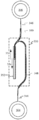
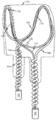
도 3g는 이어피스들(304, 306) 각각과 헤드밴드(330) 사이의 거리를 동기화되게 유지하기 위해 헤드밴드(330) 내의 루프(328)를 이용하는 다른 이어피스 동기화 시스템의 평탄화된 개략도를 도시한다(직사각형 형상은 단지 헤드밴드(330)의 위치를 나타내기 위해서만 사용되며, 단지 예시적인 목적들으로만 해석되지 않아야 함). 스템 와이어들(332, 334)은 각각의 이어피스들(304, 306)을 루프(328)에 커플링시킨다. 스템 와이어들(332, 334)은 금속으로 형성되고 루프(328)의 대향측들에 납땜될 수 있다. 스템 와이어들(332, 334)이 루프(328)의 대향측들에 커플링되기 때문에, 방향(336)으로의 이어피스(306)의 움직임은 스템 와이어(332)가 방향(338)으로 이동되는 것을 초래한다. 결과적으로, 이어피스(306)를 헤드밴드(330)와 더 근접하게 이동시키는 것은 또한 스템 와이어(332)를 이동시키며, 이는 이어피스(304)가 헤드밴드(330)와 더 근접하게 되는 것을 초래한다. 헤드밴드(330)에 더 근접하게 이동된 이후 이어피스들(304, 306)의 새로운 위치를 도시하는 것에 부가하여, 도 3h는 방향(340)으로 이어피스(304)를 이동시키는 것이 어떻게 방향(342)으로 그리고 헤드밴드(330)로부터 더 멀어지게 이어피스(306)를 자동으로 이동시키는지를 도시한다. 도시되지 않았지만, 헤드밴드(330)가 도시된 형상들로 루프(328) 및 스템 와이어들(332, 334)을 유지하기 위한 다양한 보강 부재들을 포함할 수 있음을 인식해야 한다.FIG. 3G shows a flattened schematic view of another earpiece synchronization
도 3i 및 도 3j는 도 3g 및 도 3h에 도시된 것과 유사한 다른 이어피스 동기화 시스템의 평탄화된 개략도를 도시한다. 도 3i는 스템들(344, 346)의 단부들이 개재 루프 없이 어떻게 서로 직접 커플링될 수 있는지를 도시한다. 스템들(344, 346)을 루프(328)와 유사한 형상을 갖는 패턴으로 연장시킴으로써, 부가적인 루프 구조에 대한 필요성 없이 유사한 결과가 달성될 수 있다. 스템들(344, 346)의 움직임은 보강 부재들(348, 350, 352)에 의해 보조되며, 이는 이어피스들(304, 306)의 위치가 조정되고 있는 동안 스템들(344, 346)의 좌굴을 방지하는 것을 돕는다. 보강 부재들(348 내지 352)은 스템들(344, 346)이 매끄럽게 통과하는 채널들을 한정할 수 있다. 이들 채널들은 스템들(344, 346)이 만곡되는 위치들에서 특히 도움이 될 수 있다. 만곡된 채널을 한정하지 않지만, 보강 부재(352)는 여전히 스템들(344, 346)의 단부들의 이동 방향을 방향들(354, 356)로 제한하려는 중요한 목적을 제공한다. 방향(356)으로의 움직임은 도 3j에 도시된 바와 같이, 이어피스들이 헤드밴드(330)를 향해 이동되는 것을 초래한다. 방향(354)으로의 움직임은 이어피스들(304, 306)이 헤드밴드(330)로부터 더 멀어지게 이동되는 것을 초래한다.3I and 3J show a flattened schematic view of another earpiece synchronization system similar to that shown in FIGS. 3G and 3H. 3I shows how the ends of the
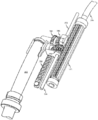
도 3k 및 도 3l은 도 3g 내지 도 3j에 도시된 이어피스 동기화 시스템들 중 어느 하나의 통합에 적합한 헤드폰(360)의 절단도들을 도시한다. 도 3k는 이어피스들이 수축되고 스템 와이어들(332, 334)이 헤드밴드(330) 외부로 연장되어 스템 조립체(362)의 위치와 스템 조립체(364)의 위치를 맞물리게 하고 동기화하는 헤드폰(360)을 도시한다. 스템(334)은 스템 조립체(364) 내에서 지지 구조체(366)에 커플링된 것으로 도시되며, 이는 스템 조립체(362)를 스템 조립체(364)와 동기화되게 유지하기 위해 스템(334)의 연장 및 후퇴를 허용한다. 도시된 바와 같이, 스템 조립체(362)는 헤드밴드(330)에 의해 한정된 채널 내에 배치되며, 이는 스템 조립체(362)가 헤드밴드(330)에 대해 이동되게 허용한다. 도 3k는 또한 데이터 동기화 케이블(368)이 어떻게 헤드밴드(330)를 통해 연장되고 스템 와이어(334) 및 스템 와이어(332) 둘 모두의 일부의 둘레를 감쌀 수 있는지를 도시한다. 스템 와이어들(332, 334) 둘레를 감쌈으로써, 데이터 동기화 케이블(368)은 스템 와이어들(332, 334)의 좌굴을 방지하기 위한 보강 부재로서 작용할 수 있다. 데이터 동기화 케이블(368)은 일반적으로 헤드폰(360)의 재생 동작들 동안 오디오를 정밀하게 동기화되게 유지하기 위해 이어피스들(304, 306) 사이에서 신호들을 교환하도록 구성된다.3K and 3L show cutaway views of
도 3l은 데이터 동기화 케이블(368)의 코일 구성이 스템 조립체들(362, 364)의 확장을 어떻게 수용하는지를 도시한다. 데이터 동기화 케이블(368)은 스템 와이어들(332, 334)이 코일들에 의해 한정된 중심 개구를 통해 활주하게 허용하는 코팅을 갖는 외부 표면을 가질 수 있다. 도 3l은 또한 이어피스들(304, 306)이 헤드밴드(330)의 중심 부분으로부터 동일한 거리를 어떻게 유지하는지를 도시한다.3L shows how the coil configuration of the
도 3m 및 도 3n은, 후퇴된 위치 및 연장된 위치에 있는 도 3g 및 도 3h에 도시된 이어피스 동기화 시스템 뿐만 아니라 데이터 동기화 케이블(368)의 사시도들을 도시한다. 도 3m은 스템 와이어(332)가 루프(328)의 일부를 적어도 부분적으로 둘러싸는 부착 특징부(370)를 어떻게 포함하는지를 도시한다. 이러한 방식으로, 스템 와이어(332), 스템 와이어(334) 및 지지 구조체들(366)이 루프(328)와 함께 이동된다. 도 3m은 또한 헤드밴드(330)에 대한 덮개가 루프(328), 스템 와이어(332) 및 스템 와이어(334)와 어떻게 적어도 부분적으로 일치할 수 있는지를 예시하는 파선을 도시한다.3M and 3N show perspective views of the
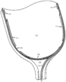
도 3o는 캐노피 구조(372)의 일부, 및 이어피스 동기화 시스템이 캐노피 구조(372)의 보강 부재들(374)을 통해 어떻게 라우팅될 수 있는지를 도시한다. 보강 부재들(374)은 원하는 경로를 따라 루프(328)와 스템 와이어(332)를 가이드하는 것을 돕는다. 일부 실시예들에서, 캐노피 구조(372)는 이어피스들을 사용자의 귀들에 고정되게 유지하는 것을 돕는 스프링 메커니즘을 포함할 수 있다.3O shows a portion of the
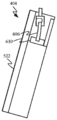
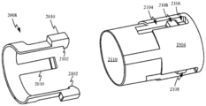
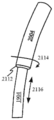
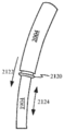
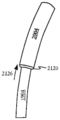
도 3p 및 도 3q는 다른 대안적인 이어피스 동기화 시스템을 위한 헤드밴드 조립체의 대향 단부들에 위치된 기어 장치를 도시한다. 특히, 도 3p는 스템(262)이 이어피스(도시되지 않음)에 결합된 제1 단부 및 기어(380)에 결합된 제2 단부를 갖는 방법을 도시한다. 이어피스를 잡아당김으로써, 힘(382)이 스템(262) 상에 가해질 수 있으며, 이는 랙 기어(384)의 맞물림으로 인해 기어(380)가 회전하게 한다. 기어(380)는 베벨형 기어 컴포넌트(386)에 견고하게 결합된다. 베벨형 기어 컴포넌트(386)는 이어서 베벨형 기어 컴포넌트(388)의 회전을 유도한다. 베벨형 기어 컴포넌트(388)는 기어(390)에 견고하게 결합된다. 기어(390)의 회전은 이어서 세장형 기어(392)의 회전을 유도한다. 기어들(380, 386, 388, 390)은 모두 함께 이동하고 베어링(394)에 의해 세장형 기어(392)의 주변부를 따라 안내된다. 세장형 기어(392)는 이어서 연관된 헤드밴드 조립체를 통해 라우팅되는 케이블(396)을 포함하는 가요성 회전 샤프트에 결합된다. 케이블(396)은 케이블(396)의 일 단부로부터 다른 단부로 회전 모션을 효율적으로 전달하도록 구성된 대향하는 피치 각도들로 서로 감긴 고-인장 와이어의 층들을 포함할 수 있다. 케이블(396)의 다른 단부의 회전은 이어서 스템(262)과 동기화되어 헤드밴드 조립체의 다른 단부에서 스템을 이동시킨다. 케이블(396)의 직경은 약 0.02 인치 내지 0.25 인치일 수 있다. 도 3q는 스템(262)의 위치를 조정한 후의 기어들(380, 386, 388, 390)의 제2 위치를 도시한다.3p and 3q show gear arrangements located at opposite ends of the headband assembly for another alternative earpiece synchronization system. In particular, FIG. 3P shows how the
오프-센터 피봇 이어피스들Off-center pivot earpieces
도 4a 및 도 4b는 오프-센터 피봇 이어피스들을 갖는 헤드폰(400)의 정면도들을 도시한다. 도 4a는 헤드밴드 조립체(402)를 포함하는 헤드폰(400)의 정면도를 도시한다. 일부 실시예들에서, 헤드밴드 조립체(402)는 헤드폰(400)의 크기를 맞춤화하기 위한 조정가능 밴드 및 스템들을 포함할 수 있다. 헤드밴드 조립체(402)의 각각의 단부는 이어피스들(404)의 상부 부분에 커플링되는 것으로 도시된다. 이는, 사용자의 머리의 표면에 평행하게 이어피스들(404)이 위치되는 각도로 이어피스들(404)이 이동되게 허용하는 방향으로 이어피스들이 자연적으로 피봇할 수 있도록 피봇점을 이어피스들(404)의 중심에 배치하는 종래의 설계들과는 상이하다. 유감스럽게도, 이러한 유형의 설계는 일반적으로 이어피스(404)의 양측으로 연장되는 부피가 큰 아암들을 요구하며, 그에 의해, 이어피스들(404)의 크기 및 중량을 실질적으로 증가시킨다. 이어피스들(404)의 최상부 부근에 피봇점(406)을 위치시킴으로써, 연관된 피봇 메커니즘 컴포넌트들이 이어피스들(404) 내에 패키징될 수 있다.4A and 4B show front views of
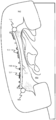
도 4b는 이어피스들(404) 각각에 대한 예시적인 모션 범위(408)를 도시한다. 모션 범위(408)는 평균 머리 크기 측정들에 대해 수행된 연구들에 기초하여 대부분의 사용자들을 수용하도록 구성될 수 있다. 이러한 보다 소형화된 구성은 여전히 위에서 설명된 보다 전통적인 구성과 동일한 기능들을 수행할 수 있는데, 그 기능은 이어피스의 중심을 통해 힘을 인가하고 음향 밀봉을 확립하는 것을 포함한다. 일부 실시예들에서, 모션 범위(408)는 약 18도일 수 있다. 일부 실시예들에서, 모션 범위(408)는 한정된 정지부를 갖지 않을 수 있지만, 대신에 그 범위가 중립 위치로부터 더 멀어지게 됨에 따라 점진적으로 변형되기에 더 어렵게 될 수 있다. 피봇 메커니즘 컴포넌트들은 헤드폰이 사용 중일 때 사용자의 귀들에 적당한 유지력을 인가하도록 구성된 스프링 요소들을 포함할 수 있다. 스프링 요소들은 또한, 일단 헤드폰(400)이 더 이상 착용되지 않으면 이어피스들을 다시 중립 위치로 가져올 수 있다.4B shows an
도 5a는 이어피스의 상부 부분에서 사용하기 위한 예시적인 피봇 메커니즘(500)을 도시한다. 피봇 메커니즘(500)은 2개의 축들을 중심으로 한 모션을 수용하도록 구성될 수 있으며, 그에 의해, 헤드밴드 조립체(402)에 대한 이어피스들(404)에 대한 롤 및 요 둘 모두에 대한 조정들을 허용한다. 피봇 메커니즘(500)은 헤드밴드 조립체에 커플링될 수 있는 스템(502)을 포함한다. 스템(502)의 일 단부는 베어링(504) 내에 위치되며, 이는 스템(502)이 요축(506)을 중심으로 회전되게 허용한다. 베어링(504)은 또한, 롤축(510)을 중심으로 한 이어피스(404)에 대한 스템(502)의 회전에 대향하는 비틀림 스프링들(508)에 스템(502)을 커플링시킨다. 비틀림 스프링들(508) 각각은 또한 장착 블록들(512)에 커플링될 수 있다. 장착 블록들(512)은 체결구들(514)에 의해 이어피스(404)의 내부 표면에 고정될 수 있다. 베어링(504)은, 베어링(504)이 장착 블록들(512)에 대해 회전되게 허용하는 부싱(bushing)들(516)에 의해 장착 블록(512)에 회전가능하게 커플링될 수 있다. 일부 실시예들에서, 롤축 및 요축은 서로에 대해 실질적으로 직교할 수 있다. 이러한 맥락에서, 실질적으로 직교한다는 것은 2개의 축들 사이의 각도가 정확히 90도가 아닐 수 있지만, 2개의 축들 사이의 각도가 85도 내지 95도에 있을 것임을 의미한다.5A shows an
도 5a는 또한 자기장 센서(518)를 도시한다. 자기장 센서(518)는 피봇 메커니즘(500) 내의 자석의 모션을 검출할 수 있는 자력계 또는 홀 이펙트(Hall Effect) 센서의 형태를 취할 수 있다. 특히, 자기장 센서(518)는 장착 블록들(512)에 대한 스템(502)의 모션을 검출하도록 구성될 수 있다. 이러한 방식으로, 자기장 센서(518)는 피봇 메커니즘(500)과 연관된 헤드폰이 언제 착용되고 있는지를 검출하도록 구성될 수 있다. 예를 들어, 자기장 센서(518)가 홀 이펙트 센서의 형태를 취할 때, 베어링(504)과 커플링된 자석의 회전은 그 자석 포화 자기장 센서(518)에 의해 방출된 자기장의 극성을 초래할 수 있다. 자기장에 의한 홀 이펙트 센서의 포화는 홀 이펙트 센서로 하여금 가요성 회로(520)에 의해 헤드폰(400) 내의 다른 전자 디바이스들로 신호를 전송하게 한다.5A also shows
도 5b는 이어피스(404)의 쿠션(522) 뒤에 위치된 피봇 메커니즘(500)을 도시한다. 이러한 방식으로, 피봇 메커니즘(500)은 사용자의 귀를 수용하기 위해 정상적으로 개방되게 유지된 공간에 충돌하지 않으면서 이어피스(404) 내에 통합될 수 있다. 확대도(524)는 피봇 메커니즘(500)의 단면도를 도시한다. 특히, 확대도(524)는 체결구(528) 내에 위치된 자석(526)을 도시한다. 스템(502)이 롤축(510)을 중심으로 회전됨에 따라, 자석(526)이 그와 함께 회전된다. 자기장 센서(518)는 자석(526)이 회전될 때 자석(526)에 의해 방출된 필드의 회전을 감지하도록 구성될 수 있다. 일부 실시예들에서, 자기장 센서(518)에 의해 생성된 신호는 헤드폰(400)을 활성화 및/또는 비활성화하는 데 사용될 수 있다. 이는, 대부분의 사용자들에 의해 착용될 때 이어피스(404)로 하여금 사용자 머리로부터 멀리 회전되게 하는 각도로 사용자를 향해 배향되는 각각의 이어피스(404)의 저부 단부에 이어피스(404)의 중립 상태가 대응할 때 특히 효과적일 수 있다. 이러한 방식으로 헤드폰(400)을 설계함으로써, 자신의 중립 위치로부터 멀어지는 자석(526)의 회전은 헤드폰(400)이 사용 중이라는 트리거로서 사용될 수 있다. 대응적으로, 자석(526)의 그의 중립 위치로의 움직임은 헤드폰(400)이 더 이상 사용 중이지 않다는 표시자로서 사용될 수 있다. 헤드폰(400)의 전력 상태들은 헤드폰(400)이 사용 중이지 않는 동안 전력을 절약하기 위해 이들 표시들에 매칭될 수 있다.5B shows the
도 5b의 확대도(524)는 또한 스템(502)이 베어링(504) 내에서 어떻게 비틀릴 수 있는지를 도시한다. 스템(502)은 나사산 캡(threaded cap)(530)에 커플링되며, 이는 스템(502)이 요축(506)을 중심으로 베어링(504) 내에서 비틀리게 허용한다. 일부 실시예들에서, 나사산 캡(530)은 스템(502)이 비틀릴 수 있는 모션 범위를 제한하는 기계식 정지부들을 한정할 수 있다. 자석(532)은 스템(502) 내에 배치되고, 스템(502)과 함께 회전되도록 구성된다. 자기장 센서(534)는 자석(532)에 의해 방출된 자기장의 회전을 측정하도록 구성될 수 있다. 일부 실시예들에서, 자기장 센서(534)로부터 센서 판독치들을 수신하는 프로세서는, 요축에 대한 자석(532)의 각도 배향의 변화의 임계량이 발생했다는 것을 센서 판독치들이 표시하는 것에 응답하여 헤드폰(400)의 동작 파라미터를 변경시키도록 구성될 수 있다.The
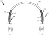
도 6a는 헤드폰의 이어피스들(404)의 최상부 부분 내에 끼워맞춰지도록 구성된 다른 피봇 메커니즘(600)의 사시도를 도시한다. 피봇 메커니즘(600)의 전체 형상은 이어피스들의 최상부 부분 내에서 이용가능한 공간에 일치하도록 구성된다. 피봇 메커니즘(600)은 이어피스들(404)의 화살표들(601)에 의해 표시된 방향들로 모션에 대향하기 위해 비틀림 스프링들 대신에 리프 스프링들을 이용한다. 피봇 메커니즘(600)은 베어링(604) 내에 배치된 일 단부를 갖는 스템(602)을 포함한다. 베어링(604)은 요축(605)을 중심으로 한 스템(602)의 회전을 허용한다. 베어링(604)은 또한 스프링 레버(608)를 통해 스템(602)을 리프 스프링(606)의 제1 단부에 커플링시킨다. 리프 스프링들(606) 각각의 제2 단부는 스프링 앵커들(610) 중 대응하는 것에 결합된다. 스프링 앵커들(610)은, 리프 스프링들(606) 각각의 제2 단부가 스프링 앵커들(610)의 중심 부분과 맞물리는 위치가 보일 수 있도록 투명한 것으로 도시된다. 이러한 위치설정은 리프 스프링들(606)이 2개의 상이한 방향들로 구부러지게 허용한다. 스프링 앵커들(610)은 각각의 리프 스프링(606)의 제2 단부를 이어피스 하우징(612)에 커플링시킨다. 이러한 방식으로, 리프 스프링들(606)은 스템(602)과 이어피스 하우징(612) 사이에 가요성 커플링을 생성한다. 피봇 메커니즘(600)은 또한 헤드밴드 조립체(402)(도시되지 않음)에 의해 2개의 이어피스들(404) 사이에서 전기 신호들을 라우팅하도록 구성된 케이블링(614)을 포함할 수 있다.6A shows a perspective view of another
도 6b 내지 도 6d는 이어피스(404)의 모션 범위를 도시한다. 도 6b는 리프 스프링들(606)이 비편향 상태에 있는 중립 상태에 있는 이어피스(404)를 도시한다. 도 6c는 제1 방향으로 편향된 리프 스프링들(606)을 도시하고, 도 6d는 제1 방향에 대향하는 제2 방향으로 편향된 리프 스프링(606)을 도시한다. 도 6c 및 도 6d는 또한 쿠션(522)과 이어피스 하우징(612) 사이의 영역이 리프 스프링들(606)의 편향을 어떻게 수용할 수 있는지를 도시한다.6B-6D show the motion range of the
도 6e는 피봇 메커니즘(600)의 분해도를 도시한다. 도 6e는 요축(605)을 중심으로 한 가능한 회전량을 관리하는 기계식 정지부들을 도시한다. 스템(602)은 상부 요 부싱(618)에 의해 한정되는 채널 내에서 이동하도록 구성된 돌출부(616)를 포함한다. 도시된 바와 같이, 상부 요 부싱(618)에 의해 한정되는 채널은 180도 초과의 회전을 허용하는 길이를 갖는다. 일부 실시예들에서, 채널은 이어피스(404)에 대한 중립 위치를 한정하도록 구성된 디텐트(detent)를 포함할 수 있다. 도 6e는 또한 요 자석(620)을 수용할 수 있는 스템(602)의 일부를 도시한다. 자석(620)에 의해 방출된 자기장은 자기장 센서(622)에 의해 검출될 수 있다. 자기장 센서(622)는 피봇 메커니즘(600)의 나머지에 대한 스템(602)의 회전 각도를 결정하도록 구성될 수 있다. 일부 실시예들에서, 자기장 센서(622)는 홀 이펙트 센서일 수 있다.6E shows an exploded view of
도 6e는 또한 리프 스프링들(606)의 편향의 양을 측정하도록 구성될 수 있는 롤 자석(624) 및 자기장 센서(626)를 도시한다. 일부 실시예들에서, 피봇 메커니즘(600)은 또한 리프 스프링(606) 내에 생성된 변형을 측정하도록 구성된 변형 게이지(628)를 포함할 수 있다. 리프 스프링(606)에서 측정된 변형은 리프 스프링이 어느 방향으로 그리고 얼마나 많이 편향되고 있는지를 결정하는 데 사용될 수 있다. 이러한 방식으로, 변형 게이지(628)에 의해 기록된 센서 판독치들을 수신하는 프로세서는 리프 스프링들(606)이 구부러져 있는지 여부 및 그 방향을 결정할 수 있다. 일부 실시예들에서, 변형 게이지로부터 수신된 판독치들은 피봇 메커니즘(600)과 연관된 헤드폰의 동작 상태를 변경시키도록 구성될 수 있다. 예를 들어, 동작 상태는 변형 게이지로부터의 판독치들에 응답하여 피봇 메커니즘(600)과 연관된 스피커들에 의해 미디어가 제시되고 있는 재생 상태로부터 대기 또는 비활성 상태로 변경될 수 있다. 일부 실시예들에서, 리프 스프링들(606)이 비편향 상태에 있을 때, 이는 피봇 메커니즘(600)과 연관된 헤드폰이 사용자에 의해 착용되지 않고 있다는 것을 표시할 수 있다. 다른 실시예들에서, 변형 게이지는 헤드밴드 스프링 상에 위치될 수 있다. 이러한 이유 때문에, 이러한 입력에 기초하여 재생을 중단하는 것은 매우 편리할 수 있는데, 그 이유는 그것이 사용자가 사용자의 머리 상에 헤드폰을 다시 놓을 때까지 미디어 파일 내의 위치를 유지하게 허용하기 때문이며, 이 점에서 헤드폰은 미디어 파일의 재생을 재개하도록 구성될 수 있다. 밀봉(630)은 피봇 메커니즘(600)의 동작을 방해할 수 있는 외래 미립자들의 침입을 방지하기 위해 스템(602)과 이어피스의 외부 표면 사이의 개구를 폐쇄할 수 있다.6E also shows a
도 6f는 피봇 메커니즘(600)과 일부 방식들에서 상이한 다른 피봇 메커니즘(650)의 사시도를 도시한다. 리프 스프링들(652)은 피봇 메커니즘(600)의 리프 스프링들(606)과 상이한 배향을 갖는다. 특히, 리프 스프링들(652)은 리프 스프링들(606)과는 약 90 도 다르게 배향된다. 이는 피봇 메커니즘(650)과 연관된 이어피스의 회전에 대향하는 리프 스프링들(652)의 두꺼운 치수를 초래한다. 도 6f는 또한 가요성 회로(654) 및 보드-보드 커넥터(656)를 도시한다. 가요성 회로는 리프 스프링(652) 상에 위치된 변형 게이지를 피봇 메커니즘(650) 상의 회로 보드 또는 다른 전기 전도성 경로들에 전기적으로 커플링시킬 수 있다. 일부 실시예들에서, 변형 게이지에 의해 제공되는 센서 데이터는 피봇 메커니즘(650)과 연관된 헤드폰이 헤드폰의 사용자에 의해 착용되고 있는지 여부를 결정하도록 구성될 수 있다. 피봇 메커니즘(650)은 또한 피봇 메커니즘(650)을 헤드밴드에 부착하도록 구성된 스템의 일부분(658)을 포함한다.6F shows a perspective view of
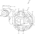
도 6g는 체결구들(662) 및 브래킷(663)에 의해 이어피스 하우징(612)에 부착된 다른 피봇 조립체(660)를 도시한다. 피봇 조립체(660)는 나란히 배열된 다수의 나선형 스프링들(664)을 포함할 수 있다. 이러한 방식으로, 나선형 코일들(664)은 피봇 조립체(660)에 의해 제공되는 저항의 양을 평행하게 증가시키는 역할을 할 수 있다. 나선형 스프링들(664)은 제 위치에서 유지되고 핀들(666, 668)에 의해 안정화된다. 액추에이터(670)는 스템 베이스(658)의 회전으로부터 수신된 임의의 힘을 나선형 스프링들(664)로 병진이동시킨다. 이러한 방식으로, 나선형 스프링들(664)은 스템 베이스(658)의 회전에 대한 원하는 양의 저항을 확립할 수 있다.6G shows another
도 6h 및 도 6i는 상이한 위치들에서의 스템 베이스(658)의 회전을 예시하기 위해 일측이 제거된 피봇 조립체(660)를 도시한다. 특히, 도 6h 및 도 6i는 스템 베이스(658)의 회전이 액추에이터(670)의 회전 및 나선형 스프링들(664)의 압축을 초래한다는 것을 도시한다.6H and 6I show the
도 6j는 이어피스 하우징(612) 내에 배치된 피봇 조립체(660)의 절단 사시도를 도시한다. 일부 실시예들에서, 스템 베이스(658)는 도시된 바와 같이, 스템 베이스(658)와 액추에이터(670) 사이의 마찰을 감소시키기 위해 베어링(674)을 포함할 수 있다. 도 6j는 또한 브래킷(663)이 핀(666)을 제 위치에 고정시키기 위한 베어링을 어떻게 한정할 수 있는지를 도시한다. 핀들(666, 668)은 또한 나선형 스프링들(664)을 제 위치에 견고하게 유지하기 위한 평탄화된 리세스들을 한정하는 것으로 도시된다. 일부 실시예들에서, 평탄화된 리세스는 나선형 스프링들(664)의 중심 개구들 내로 연장되는 돌출부들을 포함할 수 있다.6J shows a cut perspective view of the
도 6k 및 도 6l은 나선형 스프링들(664)이 이완된 상태 및 압축된 상태에 있는 이어피스 하우징 내에 위치된 피봇 조립체(660)의 부분 측단면도들을 도시한다. 특히, 도 6k의 제1 위치로부터 최대 편향의 제2 위치로 시프트될 때 액추에이터(670)에 의해 경험되는 모션이 명확하게 도시된다. 도 6k 및 도 6l은 또한 이어피스 하우징의 회전량을 제한하는 것을 돕는 기계식 정지부(676)가 스템 베이스에 대해 달성될 수 있다는 것을 도시한다.6K and 6L show partial side cross-sectional views of the
도 6m 및 도 6n은 그의 피봇 조립체로부터 격리된 스템 베이스(672)의 2개의 상이한 회전 위치들의 측면도들을 도시한다. 특히, 2개의 영구 자석들(678, 680)이 스템 베이스(672)에 견고하게 결합되는 것으로 도시된다. 영구 자석들(678, 680)은 반대 방향으로 배향된 극성들을 갖는 자기장을 방출한다. 자기장 센서(682)는 자기장 센서(682)가 회전축(684)을 중심으로 한 스템 베이스(672)의 회전 동안 스템 베이스(672)에 대해 모션 없이 유지되도록 이어피스 하우징(612)에 장착된다. 이러한 방식으로, 도 6m에 도시된 제1 위치에서, 자기장 센서(682)가 영구 자석(680)에 근접하게 위치되고, 도 6n에 도시된 제2 위치에서 자기장 센서(678)가 위치된다. 영구 자석(678, 682)들의 반대 극성들은 자기장 센서(682)가 2개의 도시된 위치들 사이를 구별할 수 있게 한다. 일부 실시예들에서, 위치들은 약 20 도만큼 변할 수 있지만; 스템 베이스(672)의 총 모션 범위는 약 10 내지 30 도로 변할 수 있다. 일부 실시예들에서, 자기장 센서(682)는 자력계 또는 홀 이펙트 센서의 형태를 취할 수 있다. 자기장 센서(682)의 감도에 따라, 자기장 센서(682)는 이어피스 하우징(612)에 대한 스템 베이스(672)의 대략적인 각도를 측정하도록 구성될 수 있다. 예를 들어, 도시된 회전 위치들이 20 도만큼 상이한 경우, 10 도의 중간 위치가 자기장 센서(682)로부터의 센서 판독치들에 의해 추론될 수 있는데, 여기서 자기장 방향들은 하나의 방향으로부터 다른 방향으로 전환한다. 일부 실시예들에서, 자기장 센서(682)는 단지 단일 영구 자석으로만 동작하도록 구성될 수 있고, 자기장 센서(682)에 의해 검출된 자기장 강도에만 기초하여 스템 베이스(672)의 회전 위치를 결정하도록 구성될 수 있다. 대안적인 실시예들에서, 자기장 센서(682)가 스템 베이스(672)에 결합될 수 있고 영구 자석들(678, 680)이 이어피스 하우징에 결합되어 자기장 센서(682)가 이어피스 하우징 내에서 이동하는 것을 초래할 수 있다는 것에 유의해야 한다.6M and 6N show side views of two different rotational positions of the
낮은 스프링-레이트 밴드Low spring-rate band
도 7a는 헤드밴드 조립체에서 사용하기에 적합한 스프링 밴드(700)의 다수의 위치들을 도시한다. 스프링 밴드(700)는, 스프링 밴드(700)의 변형에 응답하여 밴드에 의해 생성된 힘으로 하여금 변위의 함수로서 느리게 변경되게 하는 낮은 스프링 레이트를 가질 수 있다. 유감스럽게도, 낮은 스프링 레이트는 또한 스프링이 특정 양의 힘을 가하기 전에 보다 큰 변위량을 겪게 해야 한다는 것을 초래한다. 스프링 밴드(700)는 상이한 위치들(702, 704, 706, 708)에 도시된다. 위치(702)는 스프링 밴드(700)에 의해 어떠한 힘도 가해지지 않는 중립 상태에 있는 스프링 밴드(700)에 대응할 수 있다. 위치(704)에서, 스프링 밴드(700)는 스프링 밴드(700)를 그의 중립 상태를 향해 다시 밀어내는 힘을 인가하기 시작할 수 있다. 위치(706)는 스프링 밴드(700)와 연관된 헤드폰을 사용할 때 소형 머리를 갖는 사용자들이 스프링 밴드(700)를 구부리는 위치에 대응할 수 있다. 위치(708)는 큰 머리를 갖는 사용자들이 스프링 밴드(700)를 구부리는 스프링 밴드(700)의 위치에 대응할 수 있다. 위치들(702, 706) 사이의 변위는, 스프링 밴드(700)가 스프링 밴드(700)와 연관된 헤드폰을 사용자의 머리에서 떨어뜨리는 것을 방지하기에 충분한 양의 힘을 가할 만큼 충분히 클 수 있다. 추가로, 낮은 스프링 레이트로 인해, 위치(708)에서 스프링 밴드(700)에 의해 가해진 힘은, 스프링 밴드(700)와 연관된 헤드폰의 사용이 사용자의 불편함을 야기하기에 충분히 높지 않도록 충분히 작을 수 있다. 일반적으로, 스프링 밴드(700)의 스프링 레이트가 낮을수록, 스프링 밴드(700)에 의해 가해지는 힘의 변동이 작아진다. 이러한 방식으로, 낮은 스프링-레이트 스프링 밴드(700)의 사용은 스프링 밴드(700)와 연관된 헤드폰이 상이한 크기의 머리를 갖는 사용자들에게 보다 일관된 사용자 경험을 제공하게 허용할 수 있다.7A shows multiple positions of
도 7b는 스프링 밴드(700)의 변위의 함수로서 스프링 레이트에 기초하여 스프링 힘이 어떻게 변하는지를 예시한 그래프를 도시한다. 라인(710)은 위치(702)와 동등한 그의 중립 위치를 갖는 스프링 밴드(700)를 표현할 수 있다. 도시된 바와 같이, 이는 스프링 밴드(700)가 특정 쌍의 헤드폰에 대한 모션 범위의 중간에서 원하는 힘을 여전히 통과시키는 비교적 낮은 스프링 레이트를 갖게 허용한다. 라인(712)은 위치(704)와 동등한 그의 중립 위치를 갖는 스프링 밴드(700)를 표현할 수 있다. 도시된 바와 같이, 원하는 모션 범위의 중간에 가해지는 원하는 양의 힘을 달성하기 위해 더 높은 스프링 레이트가 요구된다. 마지막으로, 라인(714)은 위치(706)와 동등한 그의 중립 위치를 갖는 스프링 밴드(700)를 표현한다. 라인(714)과 일치하는 프로파일을 갖도록 스프링 밴드(700)를 설정하는 것은, 원하는 모션 범위에 대해 최소 위치에서 어떠한 힘도 스프링 밴드(700)에 의해 가해지지 않고, 최대 위치에서 라인(710)과 일치하는 프로파일을 갖는 스프링 밴드(700)와 비교하여 2배 초과의 힘의 양이 가해지는 것을 초래할 것이다. 스프링 밴드(700)와 연관된 헤드폰을 착용할 때, 원하는 모션 범위 이전에 더 많은 양의 변위를 통해 이동하도록 스프링 밴드(700)를 구성하는 것이 명확한 이점들을 갖지만, 헤드폰이 사용자의 목 둘레에 착용될 때 위치(702)로 복귀하는 것이 바람직하지 않을 수 있다. 이는 헤드폰이 사용자의 목에 불편하게 밀착되는 것을 초래할 수 있다.7B shows a graph illustrating how the spring force changes based on the spring rate as a function of the displacement of the
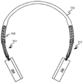
도 8a 및 도 8b는, 낮은 스프링-레이트 스프링 밴드를 이용하여 사용자의 목 둘레를 너무 단단히 감싸는 헤드폰(800)에 의해 야기되는 불편함을 방지하기 위한 해결책을 도시한다. 헤드폰(800)은 이어피스들(804)을 결합시키는 헤드밴드 조립체(802)를 포함한다. 헤드밴드 조립체(802)는 스프링 밴드(700)의 내부-대면 표면에 커플링된 압축 밴드(806)를 포함한다. 도 8a는 헤드폰(800)의 최대 편향 위치에 대응하는 위치(708)에서의 스프링 밴드(700)를 도시한다. 스프링 밴드(700)에 의해 가해지는 힘은 이러한 최대 편향 위치를 지나 헤드폰(800)을 연신시키는 것에 대한 억제제(deterrent)로서 작용할 수 있다. 일부 실시예들에서, 스프링 밴드(700)의 외부 대면 표면은 위치(708)를 지나는 스프링 밴드(700)의 편향에 대향하도록 구성된 제2 압축 밴드를 포함할 수 있다. 도시된 바와 같이, 압축 밴드(806)의 너클들(808)은, 너클들(808)의 측방향 표면들 중 어느 것도 인접한 너클들(808)과 접촉하지 않기 때문에, 스프링 밴드가 위치(708)에 있을 때 거의 역할을 하지 않는다.8A and 8B show a solution to prevent discomfort caused by
도 8b는 위치(706)에서의 스프링 밴드(700)를 도시한다. 위치(706)에서, 너클들(808)은 위치(704 또는 702)를 향한 스프링 밴드(700)의 추가의 변위를 방지하기 위해 인접한 너클들(808)과 접촉하게 된다. 이러한 방식으로, 압축 밴드(806)는 스프링 밴드(700)가 헤드폰(800)의 사용자의 목을 압착하는 것을 방지하면서, 낮은-스프링 레이트 스프링 밴드(700)의 이점들을 유지할 수 있다. 도 8c 및 도 8d는 스프링 밴드(700)가 위치(706)를 지나 복귀하는 것을 방지하기 위해 스프링 밴드(700)의 하부 측을 따라 별도의 그리고 별개의 너클들(808)이 어떻게 배열될 수 있는지를 도시한다.8B shows
도 8e 및 도 8f는 이어피스들(804)에 대한 헤드밴드 조립체(802)의 모션을 제어하기 위한 스프링들의 사용이 스프링 밴드(700) 단독에 의해 인가되는 힘과 비교할 때 헤드폰(800)에 의해 사용자에게 인가되는 힘의 양을 어떻게 변경할 수 있는지를 도시한다. 도 8e는 스프링 밴드(700)에 의해 가해지는 힘들(810) 및 헤드밴드 조립체(802)에 대한 이어피스들(804)의 모션을 제어하는 스프링들에 의해 가해지는 힘들(812)을 도시한다. 도 8f는 적어도 2개의 상이한 스프링들에 의해 공급되는 힘들(810, 812)이 스프링 변위에 기초하여 어떻게 변할 수 있는지를 예시하는 예시적인 곡선들을 도시한다. 힘(810)은, 스프링 밴드(700)가 중립 상태로 완전히 복귀하는 것을 방지하는 압축 밴드 때문에 원하는 모션 범위 직전까지 작용하기 시작하지 않는다. 이러한 이유 때문에, 힘(810)에 의해 부여되는 힘의 양은 훨씬 더 높은 레벨에서 시작하여, 힘(810)의 더 작은 변동을 초래한다. 도 8f는 또한 힘(814), 및 직렬로 작용하는 힘들(810, 812)의 결과를 예시한다. 스프링들을 직렬로 배열함으로써, 헤드폰(800)이 사용자의 머리의 크기를 수용하도록 형상을 변경시킴에 따라 결과적인 힘이 변하는 레이트가 감소된다. 이러한 방식으로, 이중 스프링 구성은 매우 다양한 머리 형상들을 포함하는 사용자 베이스에 대한 더 일관된 사용자 경험을 제공하는 것을 돕는다.8E and 8F show that the use of springs to control the motion of the headband assembly 802 relative to the
도 8g 및 도 8h는 낮은 스프링-레이트 밴드(852)를 사용하여 한 쌍의 헤드폰(850)의 모션 범위를 제한하는 다른 방식을 도시한다. 도 8g는 이어피스들(854)이 떨어져 끌어당겨지는 것으로 인해 느슨한(slack) 상태에 있는 케이블(856)을 도시한다. 낮은 스프링-레이트 밴드(852)의 모션 범위는, 압축 밴드(806)의 기능과 유사한 기능을 달성하여 압축 대신에 장력의 함수의 결과로서 맞물리는 케이블(854)에 의해 제한될 수 있다. 케이블(854)은 이어피스들(856) 사이에서 연장되도록 구성되고, 앵커링 특징부들(858)에 의해 이어피스들(856) 각각에 커플링된다. 케이블(854)은 와이어 가이드들(860)에 의해 낮은 스프링-레이트 밴드(852) 위에 유지될 수 있다. 와이어 가이드들(860)은 도 2a 내지 도 2g에 도시된 와이어 가이드들(210)과 유사할 수 있으며, 와이어 가이드들(860)이 낮은 스프링-레이트 밴드(852) 위로 케이블(854)을 상승시키도록 구성된다는 차이를 갖는다. 와이어 가이드들(860)의 베어링들은 케이블(854)이 캐칭(catch)하거나 바람직하지 않게 엉킴되는 것을 방지할 수 있다. 케이블(854) 및 낮은 스프링-레이트 밴드(852)가 장식용 덮개에 의해 덮일 수 있음에 유의해야 한다. 일부 실시예들에서, 이어피스 위치를 동기화하고 헤드폰의 모션 범위를 제어할 수 있는 헤드폰을 생성하기 위해 케이블(854)이 도 2a 내지 도 2g에 도시된 실시예들과 조합될 수 있음에 또한 유의해야 한다.8G and 8H show another way to limit the motion range of a pair of
도 8h는, 이어피스들(856)이 서로 더 가깝게 될 때, 어떻게 케이블(854)이 조여져서 결국 서로 더 가까워지는 이어피스들(856)의 추가적인 움직임을 정지시키는지를 도시한다. 이러한 방식으로, 헤드폰(850)이 사용자의 목을 너무 단단하게 압착하지 않으면서 광범위한 집단의 사용자들의 목 둘레에 착용되게 허용하는 이어피스들(856) 사이의 최소 거리(862)가 유지될 수 있다.8H shows how when the
좌측/우측 귀 검출Left/right ear detection
도 9a는 사용자의 귀(904) 위에 위치된 헤드폰의 이어피스(902)를 도시한다. 이어피스(902)는 적어도 근접 센서들(906, 908)을 포함한다. 근접 센서들(906, 908)은 이어피스(902)에 의해 한정된 리세스 내에 위치되어, 이어피스(902)가 어느 귀 위에 위치되는지에 따라 검출가능하게 상이한 판독치들이 근접 센서들(906, 908)에 의해 반환된다. 이는 대부분의 사용자의 귀의 비대칭 기하학적 구조로 인해 가능하다. 일부 실시예들에서, 근접 센서(906)는 적외광을 방출하도록 구성된 광 방출기, 및 사용자의 귀(904)에서 반사되는 방출된 광을 검출하도록 구성된 광 수신기를 포함한다. 근접 센서(906) 내에 통합되거나 그에 전기적으로 결합되는 프로세서는 광 방출기에 의해 방출된 적외선 펄스들이 광 검출기로 되돌아가는 데 걸리는 시간의 양을 측정함으로써 근접 센서(906)와 귀(904)의 근접 부분들 사이의 거리를 결정하도록 구성될 수 있다. 일부 실시예들에서, 근접 센서(906)는 또한 귀의 일부분의 윤곽을 맵핑하도록 구성될 수 있다. 이는 상이한 방향들로 상이한 주파수들의 광을 방출하도록 구성된 다수의 방출기들로 달성될 수 있다. 이어서, 상이한 주파수들을 검출 및 구별하도록 구성된 하나 이상의 광학 수신기들에 의해 수집된 센서 판독치들이 근접 센서(906)와 귀 상의 상이한 위치들 사이의 거리를 결정하는 데 사용될 수 있다. 일부 실시예들에서, 근접 센서들(906)은 이어피스에 대한 귀의 형상 및 위치에 대해 훨씬 더 많은 세부 사항이 필요한 경우 이어피스(902)의 원주 주위에 분포될 수 있다. 예를 들어, 일부 실시예들에서, 이어피스가 어느 귀에 위치되어 있는지를 식별하는 것에 더하여, 이어피스에 대한 귀의 회전 위치를 식별하는 것이 바람직할 수 있다. 센서 판독치들은 예를 들어 귓볼 또는 귓바퀴와 같은 귀(904)의 소정 특징부들을 식별하기 위해 충분히 높은 품질의 것일 수 있다. 일부 실시예들에서 그리고 도시된 바와 같이 적외선 광이 근접 센서(908)로부터 방출되는 각도는 적외선 광이 근접 센서(906)로부터 방출되는 각도와 상이할 수 있다. 이러한 방식으로, 사용자의 머리의 귀 또는 측면을 검출할 가능성이 증가될 수 있다. 도시된 바와 같이, 근접 센서(908)는 이어피스(902)의 내부의 외부에서 더 멀리 향하고 있는 것으로 인해 조기 검출을 달성할 수 있을 것이다. 더 얕은 각도를 갖는 근접 센서(906)는 사용자의 귀(904)의 더 큰 영역을 덮을 수 있을 것이다. 일부 실시예들에서, 용량성 센서 어레이는 이어피스(902)의 표면 바로 아래에 위치될 수 있고, 이어피스(902)의 표면(912)과 접촉하거나 근접해 있는 귀의 돌출 특징부들을 식별하도록 구성될 수 있다.9A shows the
도 9b는 표면(912) 아래에 있고 귀(904)와 연관된 귀 윤곽들(914)에 근접한 용량성 센서들(910)의 위치들을 도시한다. 귀 윤곽들(914)은 용량성 센서들(910)의 어레이에 가장 가깝게 돌출할 가능성이 가장 큰 귀(904)의 그러한 윤곽들을 표현한다. 용량성 센서들(910)은 이어피스(902)가 어느 귀에 위치되는지를 결정하기 위한 검출된 귀 윤곽들(904)의 부분들뿐만 아니라 귀(904)에 대한 이어피스(902)의 임의의 회전을 식별하도록 구성될 수 있다. 도 9b는 또한 오디오 파가 실질적으로 감쇠되지 않고 통과할 수 있는 개구들(916) 또는 천공들을 표면(912)과 용량성 센서들(910)의 어레이 둘 모두가 한정하는 방법을 나타낸다. 용량성 센서들(910)의 어레이가 단지 표면(912)의 중심 부분 아래에 배치되는 것으로 도시되어 있지만, 일부 실시예들에서 용량성 센서들(912)의 어레이는 더 크거나 더 적은 양의 커버리지를 초래하는 상이한 패턴들로 배열될 수 있다는 것을 인식해야 한다. 예를 들어, 일부 실시예들에서, 용량성 센서들(910)은 귀(904)의 형상 및 배향을 더 완전하게 특성화하기 위해 표면(912)의 대부분을 가로질러 분포될 수 있다. 일부 실시예들에서, 용량성 센서들(910) 및/또는 근접 센서들(906/908)에 의해 캡처된 위치 및 배향 데이터는 이어피스(902) 내에 배치된 스피커로부터의 오디오 출력을 최적화하는 데 사용될 수 있다. 예를 들어, 오디오 드라이버들의 어레이를 갖는 이어피스는 귀(904) 상에 중심을 두거나 그에 근접한 그러한 오디오 드라이버들만을 작동시키도록 구성될 수 있다.9B shows the locations of
도 10a는 헤드폰(1002)을 착용한 사용자(1000)의 예시적인 머리의 평면도를 도시한다. 이어피스들(1004)이 사용자(1000)의 대향 측면들 상에 도시된다. 이어피스들(1004)을 결합시키는 헤드밴드가 생략되어 사용자(1000)의 머리의 특징부들을 더 상세히 도시한다. 도시된 바와 같이, 이어피스들(1004)은, 그들이 사용자(1000)의 머리에 대해 동일 평면 상에 위치되고 사용자(1000)의 얼굴을 향해 약간 배향될 수 있도록 요축을 중심으로 회전되도록 구성된다. 큰 그룹의 사용자들에 대해 수행된 연구에서, 평균적으로, 사용자의 귀들 위에 위치될 때 이어피스들(1004)이 도시된 바와 같이 x-축 위로 오프셋되었다는 것으로 밝혀졌다. 또한, 사용자들의 99% 초과에 대해, x-축에 대한 이어피스들(1004)의 각도는 x-축 위에 있었다. 이는 헤드폰(1002)의 사용자들의 통계적으로 무관한 부분만이 이어피스들(1004)로 하여금 x-축의 전방으로 배향되게 하는 머리 형상들을 가질 것임을 의미한다. 도 10b는 헤드폰(1002)의 정면도를 도시한다. 특히, 도 10b는 이어피스들(1004)과 연관된 회전 요축들(1006), 및 이어피스들(1004) 둘 모두가 이어피스들(1004)을 결합시키는 헤드밴드(1008)의 동일한 측면을 향해 어떻게 배향되는지를 도시한다.10A shows a top view of an exemplary head of a
도 10c 및 도 10d는 헤드폰(1002)의 평면도들 및 이어피스들(1004)이 회전 요축들(1006)을 중심으로 어떻게 회전될 수 있는지를 도시한다. 도 10c 및 도 10d는 또한 헤드밴드(1008)에 의해 함께 결합되는 이어피스들(1004)을 도시한다. 헤드밴드(1008)는 헤드밴드(1008)에 대한 이어피스들(1004) 각각의 각도를 결정하도록 구성될 수 있는 요 위치 센서들(1010)을 포함할 수 있다. 각도는 헤드밴드(1008)에 대한 이어피스들의 중립 위치에 대해 측정될 수 있다. 중립 위치는 이어피스들(1004)이 헤드밴드(1008)의 중심 구역을 향해 직접 배향되는 위치일 수 있다. 일부 실시예들에서, 이어피스들(1004)은 외력에 의해 작용되지 않을 때 이어피스들(1004)을 중립 위치로 복귀시키는 스프링들을 가질 수 있다. 중립 위치에 대한 이어피스들의 각도는 시계 방향 또는 반시계 방향으로 변경될 수 있다. 예를 들어, 도 10c에서, 이어피스(1004-1)는 반시계 방향으로 회전축(1006-1)을 중심으로 바이어싱되고, 이어피스(1004-2)는 시계 방향으로 회전축(1006-2)을 중심으로 바이어싱된다. 일부 실시예들에서, 센서들(1010)은 이어피스들(1004)의 각도 변화를 측정하도록 구성된 비행 시간 센서들일 수 있다. 센서(1010)와 연관되고 센서(1010)로서 표시된 도시된 패턴은 이어피스들 각각의 회전량의 정확한 측정을 허용하는 광학 패턴을 표현할 수 있다. 다른 실시예들에서, 센서들(1010)은 도 5b 및 도 6e와 관련하여 설명된 바와 같은 자기장 센서들 또는 홀 이펙트 센서들의 형태를 취할 수 있다. 일부 실시예들에서, 센서들(1010)은 각각의 이어피스가 사용자에 대해 어느 귀를 덮고 있는지를 결정하는 데 사용될 수 있다. 이어피스들(1004)이 거의 모든 사용자들에 대해 x-축 뒤에 배향되는 것으로 알려져 있기 때문에, 센서들(1010)이 x-축의 일측을 향해 배향되는 이어피스들(1004) 둘 모두를 검출할 때, 헤드폰(1002)은 어느 이어피스들이 어느 귀 상에 있는지를 결정할 수 있다. 예를 들어, 도 10c는 이어피스(1004-1)가 사용자의 좌측 귀 상에 있는 것으로 결정될 수 있고 이어피스(1004-2)가 사용자의 우측 귀 상에 있는 구성을 도시한다. 일부 실시예들에서, 헤드폰(1002) 내의 회로는 오디오 채널들을 조정하여 정확한 채널이 정확한 귀에 전달되도록 구성될 수 있다.10C and 10D show top views of the
유사하게, 도 10d는 이어피스(1004-1)가 사용자의 우측 귀 상에 있고 이어피스(1004-2)가 사용자의 좌측 귀 상에 있는 구성을 도시한다. 일부 실시예들에서, 이어피스들이 x-축의 동일한 측면을 향해 배향되지 않을 때, 헤드폰(1002)은 오디오 채널들을 변경시키기 전에 추가적인 입력을 요청할 수 있다. 예를 들어, 이어피스들(1004-1, 1004-2) 둘 모두가 시계 방향으로 바이어싱되는 것으로 검출될 때, 헤드폰(1002)과 연관된 프로세서는 헤드폰(1002)이 현재 사용 중이 아니라고 결정할 수 있다. 일부 실시예들에서, 헤드폰(1002)은, 사용자가 요 위치 센서들(1010)과 연관된 L/R 오디오 채널 라우팅 로직과 독립적으로 오디오 채널들을 플립(flip)하기를 원하는 경우에 대한 오버라이드(override) 스위치를 포함할 수 있다. 다른 실시예들에서, 다른 센서 또는 센서들이 사용자에 대한 헤드폰(1002)의 위치를 확인하기 위해 활성화될 수 있다.Similarly, FIG. 10D shows a configuration in which the earpiece 1004-1 is on the user's right ear and the earpiece 1004-2 is on the user's left ear. In some embodiments, when the earpieces are not oriented toward the same side of the x-axis, the
도 10e 및 도 10f는 헤드밴드에 대한 이어피스들의 롤 및/또는 요가 검출될 때 수행될 수 있는 제어 방법들을 설명하는 흐름도들을 도시한다. 도 10e는 요축을 중심으로 한 헤드폰의 헤드밴드에 대한 이어피스들의 회전의 검출에 대한 응답을 설명하는 흐름도를 도시한다. 요축들은 각각의 이어피스와 헤드밴드 사이의 계면 부근에 위치된 지점을 통해 연장될 수 있다. 헤드폰이 사용자에 의해 사용되고 있을 때, 요축들은 사용자의 시상 및 관상 해부학적 평면들의 교점을 한정하는 벡터에 실질적으로 평행할 수 있다. 1052에서, 요축들을 중심으로 한 이어피스들의 회전은 피봇 메커니즘과 연관된 회전 센서에 의해 검출될 수 있다. 일부 실시예들에서, 피봇 메커니즘은 요축들(506, 605)을 도시하는 피봇 메커니즘(500) 또는 피봇 메커니즘(600)과 유사할 수 있다. 1054에서, 요축을 중심으로 한 회전과 연관된 임계치가 초과되었는지 여부에 관한 결정이 이루어질 수 있다. 일부 실시예들에서, 2개의 이어피스들의 귀-대면 표면들이 서로를 향해 직접 대면하고 있을 수 있는 위치를 이어피스들이 통과할 때마다, 요 임계치가 충족될 수 있다. 1056에서, 이어피스들 중 적어도 하나가 임계치를 통과하고 이어피스들 둘 모두가 동일한 방향으로 배향되는 것으로 결정되는 경우, 2개의 이어피스들로 라우팅되는 오디오 채널들이 교환될 수 있다. 일부 실시예들에서, 사용자는 오디오 채널들의 변경을 통지받을 수 있다. 일부 실시예들에서, 피봇 메커니즘에 의해 검출된 롤의 양은 오디오 채널들을 어떻게 할당할지의 결정으로 고려될 수 있다.10E and 10F show flow charts illustrating control methods that can be performed when roll and/or yoga of the earpieces for the headband are detected. 10E shows a flow chart describing the response to detection of rotation of the earpieces relative to the headband of the headphone about the yaw axis. The yaw axes may extend through a point located near the interface between each earpiece and headband. When headphones are being used by the user, the yaw axes may be substantially parallel to the vector defining the intersection of the user's sagittal and coronary anatomical planes. At 1052, rotation of the earpieces around the yaw axes can be detected by a rotation sensor associated with the pivot mechanism. In some embodiments, the pivot mechanism can be similar to the
도 10f는 헤드폰의 하나 이상의 센서들로부터의 센서 판독치들에 기초하여 헤드폰의 동작 상태를 변경하기 위한 방법을 설명하는 흐름도를 도시한다. 1062에서, 최종 패키징 동작 전에, 헤드폰은 전력이 거의 또는 전혀 소비되지 않는 동면 상태에 두어질 수 있다. 이러한 방식으로, 헤드폰(1062)은 전달시에 상당한 양의 배터리 전력을 남아 있을 수 있다. 전달 요원은 헤드폰을 동면 상태로부터 제거하기 위해 특별한 절차를 수행할 수 있다. 예를 들어, 헤드폰의 충전 포트와 맞물린 데이터 커넥터가 제거되어 동면 상태로부터의 제거를 트리거링할 수 있다. 1063에서, 헤드폰은 임계량의 시간 동안 사용되지 않을 때마다 보류 상태에 있을 수 있다. 보류 상태에서, 센서 폴링 레이트들은 전력을 추가로 보존하기 위해 실질적으로 감소될 수 있다. 일부 실시예들에서, 헤드폰은 헤드폰을 사용하려고 시도하는 사용자를 식별하기 위해 정상보다 더 오래 걸릴 수 있다. 1064에서, 변형 게이지 또는 용량성 센서가 사용자의 머리 상의 헤드폰의 배치를 식별하는 데 사용될 수 있다. 일부 실시예들에서, 방법은 모션 타임아웃이 발생하거나 헤드폰이 착용되고 있지 않음을 변형 게이지가 나타낼 때 1063에서 보류 상태로 복귀하는 단계를 포함할 수 있다. 1065에서, 용량성 또는 근접 유형 센서들이 이어피스들 내의 귀의 존재 및/또는 배향을 감지하는 데 사용될 수 있다. 1066에서, 사용자의 머리 상의 헤드폰의 배향이 식별되면, 입력 제어들이 활성화될 수 있다. 1067에서, 미디어 재생은 무선으로 또는 유선 케이블을 통해 수신된 오디오 채널들을 대응하는 이어피스들로 라우팅함으로써 시작할 수 있다. 사용자의 귀로부터 헤드폰을 제거하는 것은 1064로의 복귀로 이어질 수 있으며, 이 때 센서들은 이어피스 위치들 및 배향들을 정확하게 식별하기 위해 다양한 단계들을 통해 되돌아갈 수 있다.10F shows a flow diagram illustrating a method for changing the operational state of a headphone based on sensor readings from one or more sensors of the headphone. At 1062, before the final packaging operation, the headphones can be put into hibernation with little or no power consumption. In this way, the
도 10g는 일부 실시예들에 따른, 본 명세서에 설명된 다양한 컴포넌트들을 구현하는 데 사용될 수 있는 컴퓨팅 디바이스(1070)의 시스템 레벨 블록 다이어그램을 도시한다. 특히, 상세도는 도 10a 내지 도 10d에 도시된 헤드폰(1002)에 포함될 수 있는 다양한 컴포넌트들을 예시한다. 도 10g에 도시된 바와 같이, 컴퓨팅 디바이스(1070)는 컴퓨팅 디바이스(1070)의 전반적인 동작을 제어하기 위한 마이크로프로세서 또는 제어기를 표현하는 프로세서(1072)를 포함할 수 있다. 컴퓨팅 디바이스(1070)는 헤드밴드 조립체에 의해 결합된 제1 및 제2 이어피스들(1074, 1076)을 포함할 수 있으며, 이어피스들은 사용자에게 미디어 콘텐츠를 제시하기 위한 스피커들을 포함한다. 프로세서(1072)는 제1 및 제2 오디오 채널들을 제1 및 제2 이어피스들(1074, 1076)에 송신하도록 구성될 수 있다. 일부 실시예들에서, 제1 배향 센서(들)(1078)는 제1 이어피스(1074)의 배향 데이터를 프로세서(1072)에 송신하도록 구성될 수 있다. 유사하게, 제2 배향 센서(들)(1080)는 제2 이어피스(1076)의 배향 데이터를 프로세서(1072)에 송신하도록 구성될 수 있다. 프로세서(1072)는 제1 및 제2 배향 센서들(1078, 1080)로부터 수신된 정보에 따라 제1 오디오 채널을 제2 오디오 채널과 교환하도록 구성될 수 있다. 데이터 버스(1082)는 적어도 배터리/전원(1084), 무선 통신 회로(1084), 유선 통신 회로(1082), 컴퓨터 판독가능 메모리(1080) 및 프로세서(1072) 사이의 데이터 전달을 용이하게 할 수 있다. 일부 실시예들에서, 프로세서(1072)는 제1 및 제2 배향 센서들(1078, 1080)에 의해 수신된 정보에 따라 배터리/전원(1084)에 명령하도록 구성될 수 있다. 무선 통신 회로(1086) 및 유선 통신 회로(1088)는 프로세서(1072)에 미디어 콘텐츠를 제공하도록 구성될 수 있다. 일부 실시예들에서, 프로세서(1072), 무선 통신 회로(1086) 및 유선 통신 회로(1088)는 컴퓨터 판독가능 메모리(1090)로부터 정보를 송신 및 수신하도록 구성될 수 있다. 컴퓨터 판독가능 메모리(1090)는 단일 디스크 또는 다수의 디스크들(예를 들어, 하드 드라이브들)을 포함할 수 있고, 컴퓨터 판독가능 메모리(1090) 내의 하나 이상의 파티션들을 관리하는 저장 관리 모듈을 포함할 수 있다.10G shows a system level block diagram of a
접이식 헤드폰Folding headphones
도 11a 및 도 11b는 변형가능 폼 팩터를 갖는 헤드폰(1100)을 도시한다. 도 11a는 이어피스들(1104)을 기계적으로 그리고 전기적으로 커플링시키도록 구성될 수 있는 변형가능 헤드밴드 조립체(1102)를 포함하는 헤드폰(1100)을 도시한다. 일부 실시예들에서, 이어피스들(1104)은 이어 컵(ear cup)들일 수 있고, 다른 실시예들에서, 이어피스들(1104)은 온-이어 이어피스들일 수 있다. 변형가능 헤드밴드 조립체(1102)는 헤드밴드 조립체(1102)의 접이식 스템 구역들(1106)에 의해 이어피스들(1104)에 결합될 수 있다. 접이식 스템 구역들(1106)은 변형가능 밴드 구역(1108)의 대향 단부들에 배열된다. 접이식 스템 구역들(1106) 각각은, 이어피스들(1104) 각각이 변형가능 밴드 구역(1108)에 대해 회전된 이후 평탄화된 상태로 유지되게 허용하는 오버센터 로킹 메커니즘을 포함할 수 있다. 평탄화된 상태는 변형가능 밴드 구역(1108)의 곡률이 아치형 상태에서보다 더 편평해지도록 변경되는 것을 지칭한다. 일부 실시예들에서, 변형가능 밴드 구역(1108)은 매우 편평해질 수 있지만, 다른 실시예들에서, 곡률은 (하기의 도면들에 도시된 바와 같이) 더 가변적일 수 있다. 오버센터 로킹 메커니즘은, 사용자가 오버센터 로킹 메커니즘을 변형가능 밴드 구역(1108)으로부터 멀어지게 다시 회전시킬 때까지 이어피스들(1104)이 평탄화된 상태로 유지되게 허용한다. 이러한 방식으로, 사용자는 상태를 변경시키기 위한 버튼을 찾을 필요가 없지만, 단순히 이어피스를 다시 그의 아치형 상태 위치로 회전시키는 직관적인 동작을 수행한다.11A and
도 11b는 변형가능 밴드 구역(1108)과 접촉하게 회전되는 이어피스들(1104) 중 하나를 도시한다. 도시된 바와 같이, 변형가능 밴드 구역(1108)에 대한 이어피스들(1104) 중 단지 하나의 이어피스의 회전은 변형가능 밴드 구역(1108)의 절반으로 하여금 평탄화되게 한다. 도 11c는 변형가능 밴드 구역(1108)에 대해 회전된 이어피스들 중 제2 이어피스를 도시한다. 이러한 방식으로, 헤드폰(1100)은 아치형 상태(즉, 도 11a)로부터 평탄화된 상태(즉, 도 11c)로 용이하게 변환될 수 있다. 평탄화된 상태의 헤드폰에서, 헤드폰(1100)의 크기는 끝에서 끝까지 배열된 2개의 이어피스들과 동등한 크기로 감소될 수 있다. 일부 실시예들에서, 변형가능 밴드 구역은 이어피스들(1104)의 쿠션들 내로 가압될 수 있으며, 그에 의해, 헤드밴드 조립체(1102)가 평탄화된 상태에서 헤드폰(1100)의 높이에 부가되는 것을 실질적으로 방지한다.11B shows one of the
도 11d 내지 도 11f는 헤드폰(1150)의 이어피스들(1104)이 변형가능 밴드 구역(1108)의 외부-대면 표면을 향해 어떻게 접혀질 수 있는지를 도시한다. 도 11d는 아치형 상태에 있는 헤드폰(11D)을 도시한다. 도 11e에서, 이어피스들(1104) 중 하나는 변형가능 밴드 구역(1108)의 외부-대면 표면을 향해 접혀진다. 일단 이어피스(1104)가 도시된 바와 같이 제 위치에 있으면, 이어피스(1104)를 이러한 위치로 이동시키는 데 가해지는 힘은 변형가능 헤드밴드 조립체(1102)의 일측을 평탄화된 상태로 배치할 수 있는 반면, 다른 측은 아치형 상태로 유지된다. 도 11f에서, 제2 이어피스(1104)는 또한 외부-대면에 대해 접혀지는 것으로 도시된다.11D-11F show how the
도 12a 및 도 12b는, 헤드폰이 스프링 밴드의 대향 단부들을 끌어당김으로써 아치형 상태로부터 평탄화된 상태로 전환될 수 있는 헤드폰 실시예를 도시한다. 도 12a는, 예를 들어 도 11에 도시된 헤드폰(1100)일 수 있는 헤드폰(1200)을 평탄화된 상태로 도시한다. 평탄화된 상태에서, 이어피스들(1104)은 이어패드들(1202) 각각이 실질적으로 동일한 방향으로 향하도록 동일한 평면에 정렬된다. 일부 실시예들에서, 헤드밴드 조립체(1102)는 평탄화된 상태에서 이어패드들(1202) 각각의 대향 측면들과 접촉한다. 헤드밴드 조립체(1102)의 변형가능 밴드 구역(1108)은 스프링 밴드(1204) 및 세그먼트들(1206)을 포함한다. 스프링 밴드(1204)는 스프링 밴드(1204)의 각각의 단부에 끌어당김력들을 가하는 접이식 스템 구역들(1106)의 컴포넌트들을 로킹함으로써 헤드폰(1200)을 아치형 상태로 복귀시키는 것이 방지될 수 있다. 세그먼트들(1206)은 핀들(1208)에 의해 인접 세그먼트들(1206)에 연결될 수 있다. 핀들(1208)은 세그먼트들(1206)의 형상이 함께 유지될 수 있지만 또한 아치형 상태를 수용하기 위해 형상을 변경시킬 수 있도록 세그먼트들이 서로에 대해 회전되게 허용한다. 세그먼트들(1206) 각각은 또한 세그먼트들(1206) 각각을 통과하는 스프링 밴드(1204)를 수용하기 위해 중공형일 수 있다. 중심 또는 키스톤 세그먼트(1206)는 스프링 밴드(1204)의 중심과 맞물리는 체결구(1210)를 포함할 수 있다. 체결구(1210)는 스프링 밴드(1204)의 2개의 측면들을 격리시켜, 이어피스들(1104)이 도 11b에 도시된 바와 같이 평탄화된 상태로 순차적으로 회전되게 허용한다.12A and 12B show a headphone embodiment in which the headphones can be switched from an arcuate state to a flattened state by pulling opposite ends of the spring band. FIG. 12A shows a
도 12a는 또한 상부 링키지(1212), 중간 링키지(1214) 및 하부 링키지(1216)를 함께 피봇가능하게 커플링시키는 핀들에 의해 함께 결합된 3개의 강성 링키지들을 포함하는 접이식 스템 구역들(1106) 각각을 도시한다. 서로에 대한 링키지들의 모션은 또한, 중간 링키지(1214)를 하부 링키지(1216)에 결합시키는 핀(1220)에 커플링된 제1 단부 및 상부 링키지(1212)에 의해 한정되는 채널(1222) 내에 맞물린 제2 단부를 가질 수 있는 스프링 핀(1218)에 의해 적어도 부분적으로 관리될 수 있다. 스프링 핀(1218)의 제2 단부는 또한, 스프링 핀(1218)의 제2 단부가 채널(1222) 내에서 활주함에 따라 스프링 밴드(1204)에 가해지는 힘이 변경되도록 스프링 밴드(1204)에 커플링될 수 있다. 일단 스프링 핀(1218)의 제1 단부가 오버센터 로킹 위치에 도달하면, 헤드폰(1200)은 평탄화된 상태로 스냅(snap)될 수 있다. 오버센터 로킹 위치는, 스프링 핀(1218)의 제1 단부가 오버센터 로킹 위치로부터 해제되기에 충분히 멀리 이동될 때까지 이어피스(1104)를 평탄화된 위치로 유지한다. 그 지점에서, 이어피스(1104)는 그의 아치형 상태 위치로 복귀한다.12A also includes
도 12b는 아치형 상태로 배열된 헤드폰(1200)을 도시한다. 이러한 상태에서, 스프링 밴드(1204)는 최소량의 힘이 스프링 밴드(1204) 내에 저장되는 이완 상태에 있다. 이러한 방식으로, 스프링 밴드(1204)의 중립 상태는 사용자에 의해 능동적으로 착용되지 않을 때 아치형 상태에 있는 헤드밴드 조립체(1102)의 형상을 한정하는 데 사용될 수 있다. 도 12b는 또한 채널들(1222) 내의 스프링 핀들(1218)의 제2 단부의 휴지 상태, 및 스프링 밴드(1204)의 단부 상의 힘의 대응하는 감소가 어떻게 헤드폰(1200)이 아치형 상태를 취하는 것을 스프링 밴드(1204)가 돕게 허용하는지를 도시한다. 스프링 밴드(1204)의 실질적으로 전부가 도 12a 및 도 12b에 도시되지만, 스프링 밴드(1204)가 일반적으로 세그먼트들(1206) 및 상부 링키지들(1212)에 의해 숨겨질 것에 유의해야 한다.12B shows
도 12c 및 도 12d는 각각 아치형 상태 및 평탄화된 상태에 있는 접이식 스템 구역(1106)의 측면도들을 도시한다. 도 12c는 스프링 핀(1218)에 의해 가해지는 힘들(1224)이 링키지들(1212, 1214, 1216)을 아치형 상태로 유지하도록 어떻게 동작하는지를 도시한다. 특히, 스프링 핀(1218)은 상부 링키지(1212)가 핀(1226)을 중심으로 그리고 하부 링키지(1216)로부터 멀어지게 회전되는 것을 방지함으로써 링키지들을 아치형 상태로 유지한다. 도 12d는 스프링 핀(1218)에 의해 가해지는 힘들(1228)이 링키지들(1212, 1214, 1216)을 평탄화된 상태로 유지하도록 어떻게 동작하는지를 도시한다. 이러한 쌍안정 거동은 평탄화된 상태에서 핀(1226)에 의해 한정된 회전축의 대향 측면으로 시프트되는 스프링 핀(1218)에 의해 가능하게 된다. 이러한 방식으로, 링키지들(1212 내지 1216)은 오버센터 로킹 메커니즘으로서 동작가능하다. 평탄화된 상태에서, 스프링 핀(1218)은 헤드폰을 평탄화된 상태로부터 아치형 상태로 전환시키는 것에 저항하며; 그러나, 이어피스(1104)에 충분히 큰 회전력을 가하는 사용자는 스프링 핀(1218)에 의해 가해지는 힘들을 극복하여 헤드폰을 편평한 상태와 아치형 상태 사이에서 전환시킬 수 있다.12C and 12D show side views of the
도 12e는 평탄화된 상태에 있는 헤드폰(1200)의 일 단부의 측면도를 도시한다. 이러한 도면에서, 이어패드들(1202)은 사용자의 머리의 곡률에 일치하도록 구성된 윤곽을 갖는 것으로 도시된다. 이어패드들(1202)의 윤곽은 또한 헤드밴드 조립체(1102)를 구성하는 헤드밴드 조립체(1102) 및 특히 세그먼트들(1206)이 이어패드들(1202)보다 수직으로 실질적으로 더 멀리 돌출되는 것을 방지하는 것을 도울 수 있다. 일부 실시예들에서, 이어패드들(1202)의 중심 부분의 함몰부는 적어도 부분적으로 세그먼트들(1206)에 의해 그들에 가해지는 압력에 의해 야기될 수 있다.12E shows a side view of one end of the
도 13a 및 도 13b는 아치형 상태와 평탄화된 상태 사이에서 전환되기 위해 축외 케이블을 사용하는 헤드폰(1300)의 부분 단면도들을 도시한다. 도 13a는 아치형 상태에 있는 헤드폰(1300)의 부분 단면도를 도시한다. 헤드폰(1300)은, 이어피스들(1104)이 헤드밴드 조립체(1102)를 향해 회전될 때, 헤드밴드 조립체(1102)의 변형가능 밴드 구역(1108)을 평탄화하기 위해 케이블(1302)이 조여진다는 점에서 헤드폰(1200)과 상이하다. 케이블(1302)은 니켈 티타늄 합금인 NitinolTM과 같은 고탄성 케이블 재료로부터 형성될 수 있다. 확대도(1303)는 변형가능 밴드 구역(1108)이 체결구들(1306)에 의해 스프링 밴드(1204)에 체결되는 많은 세그먼트들(1304)을 어떻게 포함할 수 있는지를 도시한다. 일부 실시예들에서, 체결구들(1306)은 또한 헤드폰(1300)을 사용하는 동안 체결구들(1306)의 임의의 덜컹거림(rattling)을 방지하기 위하여 O-링에 의해 스프링 밴드(1204)에 고정될 수 있다. 세그먼트들(1304) 중 중심 세그먼트는 케이블(1302)이 세그먼트들(1304) 중 중심 세그먼트에 대해 활주하는 것을 방지하는 슬리브(1308)를 포함할 수 있다. 다른 세그먼트들(1304)은, 케이블(1302)이 헤드폰(1300)을 평탄화하도록 끌어당겨짐에 따라 케이블(1302)이 상당한 양들의 마찰을 경험하는 것을 방지하는 금속 풀리들(1310)을 포함할 수 있다. 도 13a는 또한 케이블(1302)의 각각의 단부가 회전 체결구(1312)에 어떻게 고정되는지를 도시한다. 접이식 스템 구역(1106)이 회전됨에 따라, 회전 체결구들(1312)은 케이블(1302)의 단부들이 비틀리는 것을 방지한다.13A and 13B show partial cross-sectional views of the
도 13b는 평탄화된 상태에 있는 헤드폰(1300)의 부분 단면도를 도시한다. 회전 체결구들(1312)은 케이블(1302)의 배향의 변화를 수용하기 위해 상이한 회전 위치에 도시된다. 회전 체결구들(1312)의 새로운 위치는 또한, 헤드폰(1200)에 대해 위에서 설명된 바와 같이 헤드폰(1300)이 의도하지 않게 아치형 상태로 복귀되는 것을 방지하는 오버센터 로킹 위치를 생성한다. 도 13b는 또한 세그먼트들(1304) 각각의 만곡된 기하학적 구조가 세그먼트들(1304)이 아치형 상태와 평탄화된 상태 사이에서 전환되기 위해 어떻게 서로에 대해 회전되게 허용하는지를 도시한다. 일부 실시예들에서, 케이블(1302)은 또한 도 9a 및 도 9b에 도시된 실시예와 일부 방식들에서 유사하게 스프링 밴드(1204)의 모션 범위를 제한하도록 동작가능할 수 있다. 헤드폰(1300)은 또한 평탄화된 상태에서 헤드폰(1300)의 외향 대면 표면에 부착된 입력 패널들(1314)을 포함한다. 입력 패널들(1314)은 헤드폰(1300)이 평탄화된 상태에 있을 때 사용자들이 헤드폰(1300)에 동작 명령어들을 입력할 수 있게 하는 터치 감응형 입력 표면을 정의할 수 있다. 예를 들어, 사용자는 평탄화된 상태에서 헤드폰(1300)을 이용한 미디어 재생을 계속하기를 원할 수 있다. 입력 패널들(1314)에 대한 용이한 접근은 이 상태에서 헤드폰(1300)의 동작을 간단하고 편리하게 할 것이다.13B shows a partial cross-sectional view of the
도 14a는 헤드폰(1300)과 유사한 헤드폰(1400)을 도시한다. 특히, 헤드폰(1400)은 또한 변형가능 밴드 구역(1108)을 평탄화하기 위해 케이블(1302)을 사용한다. 또한, 케이블(1302)의 중심 부분이 중심 세그먼트(1304)에 의해 유지된다. 반대로, 접이식 스템 구역(1106)의 하부 링키지(1216)는 도 12a에 도시된 하부 링키지(1216)에 대해 상향으로 시프트된다. 이어피스(1104)가 축(1402)을 중심으로 변형가능 밴드 구역(1108)을 향해 회전될 때, 스프링 핀(1404)은 회전의 제1 부분 동안 도 14b에 도시된 바와 같이 신장되도록 구성된다. 일부 실시예들에서, 스프링 핀(1404)의 신장은 이어피스가 초기 위치로부터 약 30도 회전되게 허용할 수 있다. 일단 스프링 핀들(1404)이 그들의 최대 길이에 도달하면, 축들(1402)을 중심으로 한 이어피스들(1104)의 추가적인 회전은 케이블(1302)이 끌어당겨지는 것을 초래하며, 이는 변형가능 밴드 구역(1108)으로 하여금 도 14c에 도시된 바와 같이 아치형 기하학적 구조로부터 편평한 기하학적 구조로 변경되게 한다. 지연된 끌어당김 모션은, 케이블(1302)이 초기에 끌어당겨지는 각도를 변경시킨다. 변경된 초기 각도는, 헤드폰(1400)을 아치형 상태로부터 평탄화된 상태로 전환시킬 때 케이블(1302)이 바인딩(bind)될 가능성을 더 적어지게 만들 수 있다.14A shows a
도 15a 내지 도 15f는 상이한 각도들로부터의 그리고 상이한 상태들에 있는 헤드밴드 조립체(1500)의 다양한 도면들을 도시한다. 헤드밴드 조립체(1500)는 평탄화된 상태와 아치형 상태 사이의 전환을 수용하는 쌍안정 구성을 갖는다. 도 15a 내지 도 15c는 아치형 상태에 있는 헤드밴드 조립체(1500)를 도시한다. 쌍안정 와이어들(1502, 1504)이 가요성 헤드밴드 하우징(1506) 내에 도시된다. 헤드밴드 하우징은 적어도 평탄화된 상태 및 아치형 상태를 수용하기 위해 형상을 변경시키도록 구성될 수 있다. 쌍안정 와이어들(1502, 1504)은 헤드밴드 하우징(1506)의 일 단부로부터 다른 단부로 연장되며, 사용 동안 헤드폰의 연관된 쌍을 제 위치에 고정되게 유지하기 위해 헤드밴드 조립체(1500)의 대향 단부들에 부착된 이어피스들을 통해 클램핑력을 사용자의 머리에 인가하도록 구성된다. 특히 도 15c는 헤드밴드 하우징(1506)이 다수의 중공 링크들(1508)로부터 어떻게 형성될 수 있는지를 도시하는데, 다수의 중공 링크들(1508)은 함께 힌지결합될 수 있으며, 쌍안정 와이어들(1502)이 아치형 상태 및 평탄화된 상태에 대응하는 구성들 사이에서 전환될 수 있는 공동을 공동작용식으로 형성할 수 있다. 링크들(1508)이 일측 상에서만 힌지결합되기 때문에, 링크들은 일 방향으로만 아치형 상태로 이동될 수 있다. 이는, 헤드밴드 조립체(1500)가 잘못된 방향으로 구부러져서, 그에 의해 이어피스들을 잘못된 방향으로 위치시키는 불행한 상황을 회피하는 것을 돕는다.15A-15F show various views of the
도 15d 내지 도 15f는 평탄화된 상태에 있는 헤드밴드 조립체를 도시한다. 쌍안정 와이어들(1502, 1504)의 단부들이 쌍안정 와이어들(1502, 1504)의 중심 부분보다 높은 오버센터 지점을 와이어들(1502, 1504)의 단부들이 통과하였기 때문에, 쌍안정 와이어들(1502)은 이제 헤드밴드 조립체(1500)를 평탄화된 상태로 유지하는 것을 돕는다. 일부 실시예들에서, 쌍안정 와이어들(1502)은 또한 하나의 이어피스로부터 다른 이어피스로 헤드밴드 조립체(1500)를 통해 신호들 및/또는 전력을 전달하는 데 사용될 수 있다.15D-15F show the headband assembly in a flattened state.
도 16a 및 도 16b는 접혀진 상태 및 아치형 상태에 있는 헤드밴드 조립체(1600)를 도시한다. 도 16a는 아치형 상태에 있는 헤드밴드 조립체(1600)를 도시한다. 헤드밴드 조립체는 도 15c 및 도 15f에 도시된 실시예와 유사하게, 내부 체적을 한정하는 가요성 헤드밴드 하우징을 공동작용식으로 형성하는 다수의 중공 링크들(1602)을 포함한다. 수동 링키지 힌지(1604)는 내부 체적의 중심 부분 내에 위치될 수 있고, 쌍안정 요소들(1606)을 함께 링크시킨다. 도 16a는 헤드밴드 조립체(1600)의 대향 측면들을 압착하도록 작용하는 힘들에 저항하는 아치형 구성들에 있는 쌍안정 요소들(1606, 16008)을 도시한다. 일단 헤드밴드 조립체(1600)의 대향 측면들이 쌍안정 요소들(1606, 1608)에 의해 생성된 저항력들을 극복하기에 충분한 힘으로 화살표들(1610, 1612)에 의해 표시된 방향들로 함께 밀리면, 헤드밴드 조립체(1600)는 도 16a에 도시된 아치형 상태로부터 도 16b에 도시된 접힌 상태로 전환될 수 있다. 수동 링키지 힌지(1604)는 헤드밴드 조립체(1600)의 중심 구역(1614) 둘레에 접혀지는 헤드폰 조립체(1600)를 수용한다. 도 16b는 수동 링키지 힌지(1604)가 헤드밴드 조립체(1600)의 접힌 상태를 수용하도록 어떻게 구부러져 있는지를 도시한다. 쌍안정 요소들(1606, 1608)은 헤드밴드 조립체(1600)의 대향 측면들을 서로를 향해 바이어싱시켜, 그에 의해 상태의 의도하지 않은 변화에 대향하도록 접혀진 구성들로 구성되는 것으로 도시된다. 도 16b에 도시된 접혀진 구성은, 사용자의 머리를 수용하기 위하여 헤드밴드 조립체(1600)에 의해 한정된 개방 영역이 접혀지게 허용하여, 헤드밴드 조립체(1600)가 활성 사용 중이 아닐 때 더 적은 공간을 차지할 수 있게 함으로써 실질적으로 더 작은 양의 공간을 차지하는 이점을 갖는다.16A and 16B show the
도 17 및 도 18은 접이식 헤드폰(1700)의 다양한 도면들을 도시한다. 특히, 도 17은 접힌 상태에 있는 헤드폰(1700)의 평면도를 도시한다. 이어피스들(1704, 1706) 사이에서 연장되는 헤드밴드(1702)는 와이어들(1708) 및 스프링들(1710)을 포함한다. 도시된 접힌 상태에서, 와이어들(1708) 및 스프링들(1710)은 직선형이고, 이완된 상태 또는 중립 상태에 있다. 도 18은 아치형 상태에 있는 헤드폰(1700)의 측면도를 도시한다. 헤드폰(1700)은 이어피스들(1704, 1706)을 헤드밴드(1702)로부터 멀어지게 회전시킴으로써 도 17에 도시된 접힌 상태로부터 도 18에 도시된 아치형 상태로 전환될 수 있다. 이어피스들(1704, 1706) 각각은 헤드밴드(1702)의 아치형 상태를 유지하기 위해 와이어들(1708)을 인장 상태로 유지하도록 와이어들(1708)의 단부들에 장력을 인가하는 오버센터 메커니즘(1802)을 포함한다. 와이어들(1708)은 헤드밴드(1702)를 따라 규칙적인 간격들로 분포되는 와이어 가이드들(1804)을 통해 스프링들(1710)을 따라 다수의 위치들에 힘들을 가함으로써 헤드밴드(1702)의 형상을 유지하는 것을 돕는다.17 and 18 show various views of the
텔레스코핑 스템 조립체Telescoping stem assembly
도 19는 헤드밴드 하우징(1902)의 일 측면뿐만 아니라 헤드밴드 하우징(1902)의 단부로부터 연장되는 텔레스코핑 부재(1904)를 도시한다. 헤드밴드 하우징(1902)은 텔레스코핑 부재(1904)의 텔레스코핑 모션을 수용하도록 구성될 수 있다. 헤드밴드 하우징(1902)은 다수의 채널들(1906)을 한정하며, 이는 텔레스코핑 부재(1904)가 하부 헤드밴드 하우징(1902) 내로 그리고 외부로 활주함에 따라 텔레스코핑 부재(1904)와 연관된 스프링 핑거들(1908)을 안내하는 것을 돕는다. 도 19는 또한 채널(1906)을 통해 가시적이고 헤드밴드 하우징(1902) 내에서 코일화된 동기화 케이블(1910)의 일부분을 도시한다. 동기화 케이블(1910)의 코일형 구성은 동기화 케이블(1910)이 헤드밴드 하우징(1902)에 대한 텔레스코핑 부재(1904)의 텔레스코핑에 의해 야기되는 길이의 변화들을 수용하도록 허용한다.19 shows the
도 20a는 도 19에 도시된 헤드밴드 하우징(1902)의 측면의 분해도를 도시한다. 특히, 상부 하우징 컴포넌트(2002) 및 하부 하우징 컴포넌트(2004)를 포함하는 헤드밴드 하우징(1902)이 도시되어 있다. 하부 하우징 컴포넌트(2004)는 텔레스코핑 부재(1904)를 수용하도록 구성된다. 하부 하우징 컴포넌트(2004)가 다수의 채널들(1906)을 한정하는 것으로 도시되고, 환형 부싱(2006)이 하부 하우징 컴포넌트(2004)의 일 단부 내에 배치되고, 텔레스코핑 부재(1904)의 이동 동안 마찰을 생성함으로써 하부 하우징 컴포넌트(2004)에 대한 텔레스코핑 부재(1904)의 모션을 제어하도록 구성된다. 도 20a는 또한 채널들(2006)과 맞물리도록 구성된 다수의 스프링 핑거들(2010)을 포함하는 단일 피스로서 스프링 부재(2008)를 도시한다.20A shows an exploded view of the side of the
도 20b는 단면 라인 F-F에 따른 하부 하우징 컴포넌트(2004)의 제1 단부의 단면도를 도시한다. 하부 하우징 컴포넌트(2004)는 텔레스코핑 부재(1810)와 맞물려 도시되고, 부싱(2012)은 텔레스코핑 부재(1810) 내에 위치된다. 스프링 핑거들(2008) 중 하나가 하부 하우징 컴포넌트(2004)의 채널(2006) 내에 맞물린 것으로 도시되어 있다. 일부 실시예들에서, 채널(2006)은 도 20c에 도시된 바와 같이 하부 하우징 컴포넌트(2004)의 벽을 완전히 관통하여 연장되지는 않는다. 이는 스프링 핑거(2008)가 하부 하우징 컴포넌트(2004)의 외부로부터 장식적으로 가시적이 됨이 없이 채널(2006) 내에 맞물릴 수 있게 한다.20B shows a cross-sectional view of the first end of the
도 20c는 섹션 라인 G-G에 따른 하부 하우징 컴포넌트(2004)의 제2 단부의 단면도를 도시한다. 하부 하우징 컴포넌트(2004)의 제2 단부는 상부 하우징 컴포넌트(2002)와 맞물린 것으로 도시되어 있다. 동기화 케이블(1910)은 상부 하우징 컴포넌트(2002) 및 하부 하우징 컴포넌트(2004) 둘 모두에 의해 한정된 개구를 통해 연장되는 것으로 도시된다.20C shows a cross-sectional view of the second end of the
도 20d는 부싱(2006)의 내부-대면 표면 주위에서 반경방향으로 이격된 다수의 핑거 채널들(2012)을 한정하는 부싱(2006)의 사시도를 도시한다. 핑거 채널들(2012)은 스프링 핑거들(2010)을 하부 하우징 컴포넌트(2004)의 핑거 채널들(2012)과 정렬시키도록 구성될 수 있다.20D shows a perspective view of a
도 21a는 스프링 부재(2014) 및 텔레스코핑 부재(1810)의 일 단부의 사시도를 도시한다. 도시된 바와 같이, 스프링 부재(2014)는 3개의 스프링 핑거들(2008)을 포함한다. 스프링 핑거들(2008) 각각은 텔레스코핑 부재(1810)로부터의 스프링 부재(2014)의 이탈을 방지하도록 구성된 로킹 특징부(2102)를 포함한다. 텔레스코핑 부재(1810)는 브리징 부재(2108)로 분할된 일 세트의 대응하는 개구들(2104, 2106)을 한정한다. 스프링 핑거들(2008)이 개구들(2104) 내에서 맞물릴 때, 개구(2104)의 길이는 스프링 핑거들(2008) 각각이 개구들(2104)을 통해 편향되는 것을 허용하여, 텔레스코핑 부재(1810)는 하부 하우징 컴포넌트(2004) 내로 삽입될 수 있다.21A shows a perspective view of one end of the
도 21b는 개구들(2104) 내에서 맞물린 스프링 핑거들(2008)을 도시하고, 도 21c는 개구들(2106) 내에 맞물린 스프링 핑거들(2008)을 도시한다. 로킹 특징부들(2102)이 개구들(2106) 내에서 맞물릴 때, 스프링 부재(2014)는 제거될 수 없고 채널들(2006) 내에서 맞물린 채로 유지된다. 또한, 브리징 부재(2108)는 스프링 핑거들(2008)이 텔레스코핑 부재(1810)에 의해 한정되는 내부 체적(2110) 내로 더 멀리 편향되는 것을 방지한다. 이는 스프링 핑거들(2008)의 돌출 부분들을 대응하는 채널들(2006) 내에서 고정식으로 맞물리게 유지한다. 일부 실시예들에서, 스프링 부재(2014)는 일단 스프링 핑거(2008)들이 채널(2006) 내에서 맞물리면 텔레스코핑 부재(1810)를 뒤로 당김으로써 도 21b에 도시된 위치로부터 시프트될 수 있다. 이러한 방식으로, 스프링 핑거들(2008)은 개구들(2104)로부터 개구들(2106) 내로 시프트될 수 있다.FIG. 21B shows the
도 21d 내지 도 21g는 텔레스코핑 부재(1810)가 관통 연장되는 하부 하우징 컴포넌트(2004)에 의해 한정된 개구에 위치된 다양한 로킹 메커니즘들을 도시한다. 도 21d 및 도 21e는 로킹 메커니즘(2112)을 도시한다. 도 21d에서, 로킹 메커니즘(2112)이 제1 방향(2114)으로 회전될 때, 텔레스코핑 부재(1810)는 양방향 화살표(2116)에 의해 나타낸 바와 같이 하부 하우징 컴포넌트(2004) 내로 또는 외부로 병진이동될 수 있다. 도 21e는 후속하여 로킹 메커니즘(2112)을 방향(2118)으로 회전시키는 것이 텔레스코핑 부재(1810)의 위치로 하여금 하부 하우징 컴포넌트(2004)에 대해 고정되게 하는 방법을 도시한다. 도 21f 및 도 21g는 로킹 메커니즘(2120)을 도시한다. 도 21f는 로킹 메커니즘(2120)이 하부 하우징 컴포넌트(2004)로부터 멀어지게 그리고 방향(2122)으로 텔레스코핑 부재(1810)를 향해 당겨질 때, 텔레스코핑 부재(1810)가 양방향 화살표(2124)에 의해 도시된 바와 같이 하부 하우징 컴포넌트(2004) 내로 또는 외부로 병진이동될 수 있는 방법을 도시한다. 도 21g는 로킹 메커니즘(2120)이 이어서 방향(2126)으로 하부 하우징 컴포넌트(2004)를 향해 밀릴 때, 하부 하우징 컴포넌트(2004)에 대한 텔레스코핑 부재(1810)의 위치가 고정되는 방법을 도시한다.21D-21G show various locking mechanisms located in the opening defined by the
좌굴 방지 조립체Anti-buckling assembly
도 22a 내지 도 22e는 하부 하우징 컴포넌트(2004) 내에 배치된 동기화 케이블(2010)의 일부분에 대한 다양한 연장 및 수축된 코일 구성들을 도시한다. 도 22a는 종래의 나선형 코일 구성에서 동기화 케이블(2010)의 일부분의 부분 단면도를 도시한다. 불행하게도, 이러한 구성은 도시된 바와 같이 연장된 구성(2204)으로부터 수축된 구성(2206)으로 전환될 때 측방향으로 시프트하는 개별 루프들(2202)에 취약할 수 있다. 오정렬은 동기화 케이블(2010)이 하부 하우징 컴포넌트(2004)의 내부를 문지르고 원치 않는 마찰에 기인하여 시간 경과에 따라 닳아지게 되어 동기화 케이블(2010)의 피로에 의한 실패를 유도할 수 있다.22A-22E show various extended and retracted coil configurations for a portion of the
도 22b는 동기화 코일(2010)의 루프들(2212)이 오정렬되는 것을 방지하는 것을 돕는 정렬 특징부들을 포함하도록 동기화 케이블(2010)의 단면 형상이 조정될 수 있는 방법을 도시한다. 특히, 루프들(2212)의 대향 측면들은 도시된 바와 같이 수축될 때 동기화 코일(2010)의 루프들(2212)을 자가-정렬시키는 것을 돕는 상보적인 기하학적 구조들을 갖는 정렬 특징부들을 포함할 수 있다.22B shows how the cross-sectional shape of the
도 22c는 동기화 코일(2010)의 루프들(2222)이 오정렬되는 것을 방지하는 것을 돕는 정렬 특징부들을 포함하도록 동기화 케이블(2010)의 단면 형상이 조정될 수 있는 방법을 도시한다. 특히, 루프들(2222)의 대향 측면들은 도시된 바와 같이 수축될 때 동기화 코일(2010)의 루프들(2212)을 자가-정렬시키는 것을 돕는 오목 채널들(2224) 및 볼록 리지들(2226)의 형태를 취하는 정렬 특징부들을 포함할 수 있다.22C shows how the cross-sectional shape of the
도 22d는 동기화 코일(2010)의 루프들(2232)이 오정렬되는 것을 방지하는 것을 돕는 링크 특징부들을 포함하도록 동기화 케이블(2010)의 단면 형상이 조정될 수 있는 방법을 도시한다. 특히, 루프들(2232)의 대향 측면들은 도시된 바와 같이 수축될 때 동기화 코일(2010)의 루프들(2212)을 자가-정렬시키는 것을 돕는 상보적인 후크들(2234) 및 볼록 리지들(2226)의 형태를 취하는 링크 특징부들을 포함할 수 있다. 링크 특징부들은 또한 동기화 케이블(2010)의 최대 양의 종방향 연장을 한정하는 것을 돕는다.22D shows how the cross-sectional shape of the
도 22e는 동기화 케이블(2010)이 오정렬되는 것이 방지될 수 있는 다른 구성을 도시한다. 동기화 케이블(2010)을 샤프트(2342) 주위에 권취함으로써, 동기화 케이블(2010)은 나선형 코일로서 배열되더라도 오정렬되는 것이 방지될 수 있다. 샤프트(2342)는 텔레스코핑 부재(1810)의 모션을 수용하기 위해 곡률의 약간의 변화들을 또한 허용하면서 상당한 양만큼 굽힐 가능성이 없는 강성 재료로 형성되어야 한다. 일부 실시예들에서, 샤프트(2242)는 니티놀(NITINOL)(니켈-티타늄 합금) 와이어로부터 형성될 수 있다.22E shows another configuration in which the
도 23a는 데이터 플러그(2302)와 연관된 컴포넌트들의 분해도를 도시한다. 특히, 스템 베이스(2304)의 일 단부로부터 연장되는 데이터 플러그(2302)는 텔레스코핑 부재(1810) 내의 리셉터클과 맞물리도록 구성된다. 일단 리셉터클 내에 맞물리면, 데이터 플러그(2302)는, 나사산 개구(2310)를 통해 데이터 플러그(2302)의 베이스 부분에 의해 한정되는 리세스(2308)와 맞물리도록 구성되는 나사산 체결구(2306)를 사용하여 제 위치에 고정식으로 유지될 수 있다. 밀봉 링들(2312)은 또한 텔레스코핑 부재(1810) 내에 데이터 플러그(2302)를 추가로 고정하는 데 사용될 수 있다. 도 23b는 데이터 플러그(2302)를 고정식으로 위치되게 유지하기 위해 나사산 개구(2310) 내에 완전히 맞물린 나사산 체결구(2306)를 갖는 텔레스코핑 부재(1810)의 완전한 조립체를 도시한다.23A shows an exploded view of components associated with
도 23c는 도 23b의 섹션 라인 H-H에 따른 텔레스코핑 부재(1810)의 단면도를 도시한다. 특히, 도 23c는 플러그 리셉터클(2314) 내에 맞물린 데이터 플러그(2302)의 일 단부를 도시한다. 도 23c는 또한 데이터 플러그(2302)가 제 위치에 고정된 상태로 유지하기 위해 나사산 체결구가 리세스(2308)와 협동하는 방법을 도시한다. 밀봉 링들(2312)의 위치가 또한 데이터 플러그(2302)에 대해 도시된다. 일부 실시예들에서, 데이터 플러그(2302)는 헤드폰의 연관된 이어피스 내에서 인쇄 회로 기판과 맞물리는 보드 대 보드 접속에서 종단되는 케이블 대신에 생략될 수 있다는 것에 유의해야 한다.23C shows a cross-sectional view of the
도 23d는 데이터 플러그(2302)의 일부분의 사시도를 도시한다. 특히, 데이터 플러그(2302)의 본체는 계단형 기하학적 구조를 가지며, 규칙적인 간격으로 이격된 다수의 접착 채널들(2316)을 한정한다. 일부 실시예들에서, 접착 채널들(2316)은 데이터 플러그(2302)의 본체의 외부 측면 표면 내로 레이저 절단될 수 있다. 도 23e는 데이터 플러그(2302)의 일부분의 측단면도를 도시하고, 데이터 플러그(2302)의 본체의 대향 측면들 상에 위치된 다수의 접착 채널들(2316)을 도시한다.23D shows a perspective view of a portion of data plug 2302. In particular, the body of the data plug 2302 has a stepped geometry and defines a number of
도 23f는 스템 베이스(2304)에 접착되고 이어서 이어피스(2320)에 의해 한정된 리세스(2318) 내에 위치되는 데이터 플러그(2302)를 도시한다. 도 23g는 스템 베이스(2304)에 의해 한정된 리세스 내에 배치되고 이어서 이어피스(2320)의 리세스(2318) 내에 위치된 데이터 플러그(2302)의 단면도를 도시한다. 도 23g는 도 23f에 도시된 바와 같은 단면 라인 I-I에 대응하고, 또한 데이터 플러그(2302)가 접착제 층(2322)에 의해 스템 베이스(2304)에 접착되는 방법을 도시한다. 접착제 층(2322)에 의해 스템 베이스(2304)와 데이터 플러그(2302)의 본체 사이에 형성된 결합의 강도는 접착 채널들(2316)을 맞물릴 수 있는 접착제 층(2322)으로 인해 실질적으로 증가된다. 일부 실시예들에서, 스템 베이스(2304)의 내부-대면 표면은 또한 훨씬 더 큰 접착을 위해 접착 채널들(2316)과 유사한 접착 채널들을 포함할 수 있다. 일부 실시예들에서, 접착제 층(2322)과 접촉하는 표면들 중 하나 또는 둘 모두가 조면화될 수 있어서, 표면들의 표면 에너지를 증가시키고 생성된 접착제 커플링의 강도를 개선할 수 있다. 도 23g는 또한 데이터 플러그(2302) 및 스템 베이스(2304) 둘 모두에 의해 정의된 채널들을 통해 연장되는 데이터 동기화 케이블(2324)을 도시한다.23F shows the data plug 2302 attached to the
이어패드 구성들 및 최적화Earpad configurations and optimization
도 24a는 이어피스(2402) 및 이어패드(2404)의 사시도들을 도시한다. 이어패드(2404)는 사용자의 머리(2406)의 측면이 어떻게 결코 평평하지 않은지를 예시하는 평면 형상을 갖는 것으로 도시되어 있다. 대부분의 이어패드들이 두께에서 상당히 강건한 하나의 이유는 사용자의 머리의 측면의 두측 윤곽들을 수용하기 위한 것이다. 도 24a에 도시된 점선 화살표들은 이어패드들이 두측 윤곽들과 일치하기 위해 극복할 필요가 있는 거리에서의 변동을 예시한다.24A shows perspective views of
도 24b는 헤드폰(2410)의 이어피스들(2412, 2414)이 사용자 편안함을 희생시키지 않고서 얇은 이어패드들(2416)을 가질 수 있는 방법을 도시한다. 이어패드들(2416)은 두측 윤곽들의 변동들을 수용하기 위해 미리 결정된 양의 휨을 허용하는 가요성 기판을 포함할 수 있다. 이어패드들(2416)은 이어피스 요크들(2418)에 결합될 수 있으며, 이때 2개의 포스트들(2420)은 사용자의 머리 상의 통상 낮은 지점들에 대응하는 위치들에 위치된다. 도시된 구성에서, 돌출된 두측 윤곽들과 만나는 이어패드들(2416)의 부분들은 사용자의 머리 상의 압력 지점을 방지하기 위해 다시 구부러질 수 있다. 이러한 방식으로, 사용자의 편안함을 희생시키지 않고서 더 얇은 패드들이 활용될 수 있기 때문에 상당한 양의 중량 및 재료 비용이 절약될 수 있다.24B shows how the
도 24c는 포스트들(2420)이 가요성 기판(2422)을 이어피스 요크들(2418)에 결합시키는 방법을 도시한다. 가요성 기판(2422)은 가요성 기판(2422)에 장착된 이어패드들(2416)의 변형을 허용하기에 충분한 가요성을 갖는 기판으로부터 형성된다. 가요성 기판(2422)이 이어피스 요크(2418)에 어떻게 연결되어 있는지를 명확하게 보여주기 위해 많은 컴포넌트들이 도 24c의 이어피스(2414)로부터 제거되었음에 유의해야 한다. 도 24d는 이어피스(2414), 및 이어패드(2416)가 사용자의 머리의 두측 윤곽들을 수용하도록 굽혀지게 구성된 회전축(2424)을 도시한다. 회전축(2424)은 포스트들(2420)이 가요성 기판(2422)의 후방-대면 표면 및 결과적으로 이어패드(2416)에 부착되는 위치들에 의해 한정된다.24C shows how
도 24e 내지 도 24h는 사용자의 머리의 두측 윤곽들을 고려하도록 설계된 구성의 다른 이어피스를 도시한다. 도 24e는 이어피스(2430)의 측면도를 도시한다. 이어피스(2430)는 볼록 입력 패널(2432), 이어피스 하우징(2434) 및 이어패드 조립체(2436)를 포함한다. 볼록한 입력 패널(2432)은 이어피스 하우징(2434)의 일 측면에 부착될 수 있고 이어피스와 연관된 헤드폰에 터치 입력을 수신하기 위한 센서들을 포함할 수 있다. 도 24e는 또한 이어패드 조립체(2436)의 압축성 이어패드(2438)를 도시한다. 압축성 이어패드(2438)는 폼으로부터 형성될 수 있고 실질적으로 균일한 두께를 가질 수 있다. 만곡된 기하학적 구조로 도시된 바와 같이 압축성 이어패드(2438)를 구부림으로써, 이어패드 조립체(2436)의 사용자-대면 표면은 사용자의 머리의 두측 윤곽들과 매칭하도록 형상화될 수 있다.24E-24H show another earpiece in a configuration designed to take into account the two contours of the user's head. 24E shows a side view of the
도 24f는 이어피스(2430)의 단면도뿐만 아니라, 귀(2442)를 수용하기 위한 공동(2440)의 형상을 도시한다. 이어피스(2430)를 어느 한 귀 위에 수용하도록 구성되지 않은 헤드폰 설계들에서, 스피커 조립체(2444)는 귀(2442)에 이용가능한 공간의 양에 영향을 미치지 않으면서 공동(2440) 내로 돌출될 수 있다. 일부 실시예들에서, 이러한 방식으로 스피커 조립체(2444)를 전방으로 미는 것은 이어피스(2430)의 전체 크기를 감소시킬 수 있다. 도 24f는 또한 이어패드(2438)의 언더컷 기하학적 구조가, 이어피스(2430)가 귀(2442)에 더 가까운 사용자의 머리의 일부분 주위에서 밀봉되게 하여, 사용자의 머리와 접촉하는 부분 이어패드 조립체(2436)의 주변부의 길이를 감소시키는 방법을 예시한다. 일부 실시예들에서, 이는 수동 잡음 격리를 개선할 수 있다. 이어패드(2438)는 사용자와 접촉하는 이어패드 조립체(2436)의 부분에 쾌적한 느낌을 제공하기 위해 텍스타일 재료(2446)에 의해 덮일 수 있다. 일부 실시예에서, 텍스타일 재료(2446)에 의해 제공되는 음향 격리를 개선하기 위해 텍스타일 재료(2446)에 다양한 처리들이 적용될 수 있다. 예를 들어, 텍스타일 재료(2446)의 기공 크기를 감소시키기 위해, 사용자의 머리와 접촉할 가능성이 가장 큰 텍스타일 재료(2446)의 적어도 일부분에 열 처리가 적용되어 음향 저항을 부스팅할 수 있다.24F shows the cross-section of the
도 24g는 이어피스(2430)의 사시도를 도시하고, 이어패드 조립체(2436)의 주변부 주위의 이어패드 조립체(2436)의 다양한 곡률을 더 명확하게 예시한다. 특히, 이어패드 조립체(2436)의 구역(2448)은, 머리가 목부를 향해 뒤로 기울어지기 시작하는 귀의 후방부 아래 및 그에 대해 사용자의 머리의 일부분을 접촉하도록 구성된다. 이러한 이유로, 구역(2448)은 이어패드 조립체(2436)의 임의의 다른 부분보다 이어피스(2430)로부터 실질적으로 더 멀리 돌출된다. 다소 더 작은 정도까지, 이어패드 조립체(2436)의 구역(2450)이 또한 이어피스(2430)로부터 멀리 돌출되어, 일반적으로 사용자의 귀 앞에 그리고 약간 위에 위치된 사용자의 머리 상의 다른 저점을 수용한다.24G shows a perspective view of the
도 25a 내지 도 25c는 재료의 다수의 층들로부터 형성된 다른 이어패드 구성(2500)의 다양한 도면들을 도시한다. 도 25a는 3개의 상이한 컴포넌트 층들, 즉 쿠션(2502), 유연한 구조 층(2504) 및 텍스타일 층(2506)을 포함하는 이어패드 구성(2500)의 분해도를 도시한다. 일부 실시예들에서, 쿠션(2502)은 폼으로부터 형성되고 기계가공 공정 동안 형상화될 수 있으며, 이는 아래에서 더 상세히 설명될 것이다. 유연한 구조 층(2504)은 쿠션(2502)의 주변부의 형상을 한정하는 것을 도울 수 있는 한편, 이어피스의 외부에 소정 양의 유연함을 제공한다. 일부 실시예들에서, 유연한 구조 층(2504)은 에틸렌-비닐 아세테이트 고무 블렌드로부터 형성될 수 있다. 텍스타일 층(2506)은 직물의 시트로부터 형성될 수 있고, 다수의 별개의 구역들(2508, 2510)을 포함한다. 사용자의 머리와 직접 접촉하는 직물의 대부분을 구성하는 구역(2510)은, 수동 음향 격리를 개선하기 위해 직물 내의 임의의 갭들을 밀봉하도록 열처리될 수 있다. 이는 개선된 수동 음향 격리가 능동 잡음 제거 시스템에 의해 소거될 필요가 있는 잡음의 양을 감소시킴에 따라 능동 잡음 제거 시스템을 갖는 헤드폰에 특히 중요할 수 있다. 일부 실시예들에서, 구역(2510)은 그의 다공성이 구역들(2508)의 다공도보다 실질적으로 더 작도록 열처리될 수 있다. 더 낮은 다공성 텍스타일 재료들은 일반적으로 수동 잡음 감쇠를 제공하는 데 더 효과적이다.25A-25C show various views of another
도 25b는 이어패드 구성(2500)과 연관된 헤드폰에 의해 수신된 미디어 파일들의 재생을 지원하는 다양한 전기 컴포넌트들을 수용하도록 구성된 내부 체적(2514)을 정의하는 전자장치 하우징 컴포넌트(2512) 주위에 유연한 구조 층(2504) 및 텍스타일 층(2506)과 함께 폼 쿠션(2502)이 형성될 수 있는 방법을 도시한다. 도 25b는 또한, 텍스타일 층(2506)의 개구(2516)가 I/O 포트 또는 입력 제어부를 수용하기 위해 전자장치 하우징 컴포넌트(2512)의 개구(2518)와 정렬되도록 구성되기 때문에, 전자장치 하우징 컴포넌트(2512)에 의해 한정된 개구들과 텍스타일 층(2506)을 정렬시키는 것의 중요성을 예시한다. 또한, 개구(2520)는 또한 하우징 컴포넌트(2512)의 포스트(2522)와 정렬될 필요가 있을 수 있다.25B is a flexible structural layer around the
도 25c는 이어패드 구성(2500)의 측단면도를 도시한다. 특히, 도 25c는 텍스타일 층(2506)이 열처리된 구역(2510)의 상이한 측면들 상에 위치된 2개의 구역들(2508)을 포함하는 방법, 및 유연한 구조 층(2504)이 텍스타일 층(2506)의 구역(2510) 아래에서 연장되는 방법을 도시한다. 도 25d는 헤드폰이 활성 사용 중일 때 텍스타일 층(2506)의 열처리된 구역들(2510)이 사용자의 머리의 측면과 직접 접촉하는 방법을 도시한다. 이러한 방식으로, 효과적인 장벽은 사용자의 머리와 이어패드 구성(2500) 사이의 오디오 파들의 통로에 대해 열처리된 구역들(2510)에 의해 형성되며, 이는 일반적으로 이어패드들을 덮기 위해 텍스타일 재료를 사용하는 헤드폰에 대해 실행가능한 것으로 간주되지 않을 것이다. 구역(2510)이 사용자의 얼굴과 접촉하는 표면을 완전히 가로질러 연장되는 것으로 도시되어 있지만, 소정 실시예들에서는, 사용자와 접촉하는 텍스타일 직물의 일부분만이 열처리를 겪었음이 이해되어야 한다.25C shows a side cross-sectional view of the
도 26a 및 도 26b는 개방 셀 폼과 같은 순응성 재료로 형성될 수 있는 이어패드(2602)의 사시도들을 도시한다. 헤드폰을 위한 종래의 폼 패드들은 직사각형 블록들로부터 형성되고, 기계가공 방법들을 사용하여 형성되는 경우, 스탬핑 공정에 의해 형성될 것이다. 더 큰 블록으로부터 이어패드들(2602)을 기계가공함으로써, 정밀한 3차원 형상이 달성될 수 있다. 기계가공은 또한 사출을 수행하는 것에 비해 우수한데, 그 이유는 이들 유형들의 공정들이 원하는 형상을 달성하기 위한 몰드를 포함할 수 있지만, 몰딩 공정 동안 일어나는 가열 공정들로 인해 표면 일관성이 흔히 실질적으로 상이하기 때문이다. 적어도 이러한 이유들로, 이어패드 쿠션으로서의 기계가공된 폼의 성능은 대안들보다 실질적으로 더 양호한데, 그 이유는, 폼의 요구되지 않은 부분들이 용이하게 절단되게 함으로써, 압력에 대한 맞춤형 응답성을 허용하고 각각의 이어패드 쿠션의 전체 중량을 감소시키는 것을 허용하기 때문이다. 도시된 바와 같이, 이어패드(2602)는 도 26a 및 도 26b에 도시된 바와 같이, 이어패드(2602)의 원하는 견고함을 확립하는 것을 돕는 언더컷 기하학적 구조를 이어패드(2602)에 제공하는 점진적으로 기울어지는 기하구조를 양측에 갖는다.26A and 26B show perspective views of
도 26c 내지 도 26g는 폼의 블록으로부터 이어패드를 형성하기 위한 다양한 제조 동작들을 도시한다. 도 26c는 일단 그것이 압출 또는 몰딩 공정에 의해 형성되면 개방 셀 폼 블록(2604)을 도시한다. 도 26d에서, 프로파일 커터(2606) 및 볼 엔드 밀(2608)은 폼 블록(2604)으로부터 이어패드(2602)의 대향 측면들을 형성하는 것으로 도시되어 있다. 일부 실시예들에서, 절단 및 밀링 공정은 먼저 도 26e에 도시된 바와 같이 폼 블록(2610)을 물에 침지시키고 이어서 도 26f에 도시된 바와 같이 폼 블록을 동결시킴으로써 더 정확하게 제조될 수 있다. 일부 실시예들에서, 프로파일 커터(2606) 및 볼 엔드 밀(2608)이 폼 블록(2610)을 동결시키기 위해 적용될 때, 기계가공 동작들은 폼 재료가 기계가공 공구들에 의해 인가되는 압력의 양 하에서 이동 및 변형될 가능성이 더 적기 때문에, 조금 더 정확할 수 있다. 환형 이어패드는 실질적으로 직사각형인 단면 기하학적 구조를 갖는 것으로 도시되어 있지만, CNC 공정은 훨씬 더 광범위한 다양한 형상들을 허용한다. 예를 들어, 프로파일 커터(2606) 및 볼 엔드 밀(2608)에 의해 수행되는 기계가공 동작들을 변화시킴으로써 눈물방울, 원형, 정사각형, 타원형, 다각형 및 다른 단면 기하학적 구조들이 실현될 수 있다. 스플라인(spline) 기하학적 구조들과 같은 비-유클리디언 표면 형상들이 또한 전술한 기계가공 기술을 사용하여 완전히 실현될 수 있다.26C-26G show various manufacturing operations for forming the ear pads from a block of foam. 26C shows the open
스피커 조립체Speaker assembly
도 27a는 앞서 기술된 이어피스들 중 임의의 것에 적용될 수 있는 이어피스(2700) 내의 예시적인 음향 구성의 측단면도를 도시한다. 음향 구성은 다이어프램(2704) 및 전기 전도성 코일(2706)을 포함하는 스피커 조립체(2702)를 포함하고, 전기 전도성 코일(2706)은 영구 자석들(2708, 2710)에 의해 방출된 자기장과 상호작용하는 시프팅 자기장을 발생시키기 위한 전류를 수신하도록 구성되어, 다이어프램(2704)이 발진하게 하고 천공된 벽(2709)을 통해 이어피스 조립체를 빠져나가는 오디오 파들을 발생시키게 한다. 일부 실시예들에서, 천공된 벽(2709)은 도 9a 및 도 9b에 도시된 바와 같은 용량성 센서들의 어레이를 포함할 수 있다. 구멍이 영구 자석(2708)의 중심 구역을 통해 드릴링되어, 다이어프램(2704) 뒤의 후방 체적의 공기를 메시 층(2716)을 통해 내부 체적(2714)과 유체 연통하는 개구(2712)를 한정함으로써, 스피커 조립체(2702)의 후방 체적의 유효 크기를 증가시킬 수 있다. 내부 체적(2714)은 공기 통기구(2718)까지 쭉 연장된다. 공기 통기구(2718)는 스피커 조립체(2702)의 후방 체적의 유효 크기를 추가로 증가시키도록 구성될 수 있다. 예를 들어, 공기 통기구(2718)는 스피커 조립체(2702)의 성능을 증강시키기 위한 베이스 리플렉스 통기구로서 작용할 수 있다. 스피커 조립체(2702)의 후방 체적은 스피커 프레임 부재(2720) 및 입력 패널(2722)에 의해 추가로 한정될 수 있다. 일부 실시예들에서, 입력 패널(2722)은 스피커 프레임 부재(2720)로부터 약 1 mm만큼 분리될 수 있다. 스피커 프레임 부재(2720)는 오디오 파들이 후방 체적을 라우팅하는 추가적인 도관을 통해 이동하게 하는 개구(2724)를 한정한다. 접착 채널(2726)은 스피커 프레임 부재(2720)의 돌출부들(2728)에 의해 한정된다.27A shows a cross-sectional side view of an exemplary acoustic configuration within
도 27b는 스피커 조립체(2702)와 연관된 내부 체적의 형상 및 크기를 예시하기 위해 입력 패널(2722)이 제거된 이어피스(2700)의 외부를 도시한다. 도시된 바와 같이, 이어피스(2700)의 중심 부분은 영구 자석들(2708, 2710)을 포함한다. 스피커 프레임 부재(2720)는 내부 체적(2714)를 한정하는 리세스 구역을 포함한다. 내부 체적(2714)는 도 27a에 도시된 바와 같이 약 20 mm의 폭 및 약 1 mm의 높이를 가질 수 있다. 내부 체적(2714)의 단부에는 스피커 프레임 부재(2720)에 의해 한정되는 개구(2724)가 있으며, 이는 후방 체적이 접착 채널(2726) 아래에서 계속되고 이어피스(2700) 외부로 이어지는 공기 통기구(2718)로 연장될 수 있도록 구성된다.27B shows the exterior of the
도 27c는 이어피스(2700) 내에 장착된 마이크로폰의 단면도를 도시한다. 일부 실시예들에서, 마이크로폰(2730)은 스피커 프레임 부재(2720)에 의해 한정된 개구(3732)를 가로질러 고정된다. 개구(3732)는 마이크로폰 흡입 통기구(2734)로부터 오프셋되어, 사용자가 이어피스(2700)의 외부로부터 개구(2732)를 보는 것을 방지한다. 장식적 개선을 제공하는 것에 더하여, 이러한 오프셋 개구 구성은 또한 마이크로폰(2730)이 마이크로폰 흡입 통기구(2734)에 의해 신속하게 통과하는 공기로부터 잡음을 픽업하는 것을 감소시키는 경향이 있다.27C shows a cross-sectional view of a microphone mounted within the
도 28은 이어피스(2700)의 외부 대면 표면을 형성할 수 있는 입력 패널(2720)을 갖는 이어피스(2700)를 도시한다. 터치 감응형 구역은 터치 센서(2802)에 의해 확립될 수 있으며, 이는 입력 패널(2720)의 내부 대면 표면에 부착된 가요성 기판의 형태를 취할 수 있다. 가요성 기판은 다수의 노치들(2804)을 한정할 수 있으며, 이는 가요성 기판이 입력 패널(2720)의 내부-대면 표면의 오목 형상과 일치하도록 허용하는 변형 완화 특징부들로서 기능한다. 수동 라디에이터(2806)는 터치 센서(2802)에 인접하게 도시되고 또한 무선 투명 입력 패널(2720)의 내부-대면 표면에 부착된다. 수동 라디에이터(2806)는 스탬핑된 금속 시트로부터 형성될 수 있거나, 가요성 인쇄 회로를 따라 형성될 수 있다. 이러한 구성은 수동 라디에이터(2806)와 터치 센서(2802) 사이의 간섭을 방지한다. 수동 방사기(2806)는 내부 안테나(2808)와 협동할 수 있으며, 이는 또한 이어피스(2700) 내에 위치되어 무선 성능을 개선한다.28 shows an
분산 배터리 구성Distributed battery configuration
도 29a 및 도 29b는 이어피스(2900) 내의 분산 배터리 조립체들(2902, 2904)의 위치를 예시하는 이어피스(2900)의 윤곽의 사시도 및 단면도를 도시한다. 특히, 도 29a는 배터리 조립체들(2902, 2904)이 이어피스(2900)의 하우징의 대향 측면들 상에 위치될 수 있는 방법을 도시한다. 도 29b는 단면 라인 J-J에 따른 이어피스(2900)의 단면도를 도시한다. 배터리 조립체들(2902, 2904)은 또한 이어피스(2900)에 의해 한정되는 이어 공동(2906)의 크기를 최대화하기 위해, 도 29b에 도시된 바와 같이 이어피스(2900)에 의해 한정되는 귀 공동에 대해 대각선으로 기울어질 수 있다. 도 29c는 2개 초과의 별개의 배터리 조립체들이 단일 이어피스 하우징 내에 통합될 수 있는 방법을 도시한다. 예를 들어, 도 29c에 도시된 바와 같이, 3개, 4개, 5개 또는 6개의 개별 배터리 조립체들이 이어피스(2900)의 주변부를 따라 분포될 수 있다. 일부 실시예들에서, 그리고 도 29c에 도시된 바와 같이, 배터리 조립체들(2908 내지 2914)은 이어피스 하우징의 외측 주변부의 곡률 및 더 일반적으로 이어피스 하우징 내에서 이용가능한 공간을 따르는 곡률을 갖는다. 개별 배터리 조립체들 각각은 이어피스(2900) 내의 다양한 컴포넌트들의 동작을 지원하도록 구성된 그들 자신의 입력 및 출력 단자들을 가질 수 있다.29A and 29B show perspective and cross-sectional views of the contour of
도 30a는 헤드밴드(3006)에 의해 함께 결합된 이어피스들(3002, 3004)을 포함하는 헤드폰(3000)을 도시한다. 헤드밴드(3006)의 중심 부분은 이어피스들(3002, 3004) 내의 컴포넌트들에 초점을 맞추기 위해 생략되었다. 특히, 이어피스들(3002, 3004)은 홀 이펙트 센서들 및 영구 자석들의 혼합을 포함할 수 있다. 도시된 바와 같이, 이어피스(3002)는 영구 자석(3008) 및 홀 이펙트 센서(3010)를 포함한다. 영구 자석(3008)은 남극 극성을 갖는 이어피스(3002)로부터 멀리 연장되는 자기장을 생성한다. 이어피스(3004)는 홀 이펙트 센서(3012) 및 영구 자석(3014)을 포함한다. 도시된 구성에서, 영구 자석(3008)은 홀 이펙트 센서(3012)를 포화시키기에 충분히 강한 자기장을 출력하도록 위치된다. 홀 이펙트 센서(3012)로부터의 센서 판독치들은 헤드폰(3000)이 능동적으로 사용되고 있지 않고 에너지 절약 모드에 진입할 수 있음을 헤드폰(3000)을 큐하기에 충분할 수 있다. 일부 실시예들에서, 이러한 구성은 또한 헤드폰(3000)이 케이스 내에 위치되어 있고 배터리 전력을 절약하기 위해 저전력 동작 모드에 진입해야 함을 헤드폰(3000)에 큐할 수 있다. 이어피스들(3002, 3004)을 각각 180 도로 플립하는 것은 영구 자석(3014)에 의해 방출된 자기장이 홀 이펙트 센서(3010)를 포화시키고, 이는 또한 디바이스가 저전력 모드에 진입하게 할 것이다. 사용자가 머리 구성 밖에서 헤드폰을 동작시키기 위해 이어피스들(3002, 3004)을 상방으로 향하도록 설정하기를 원할 수 있고, 그러한 경우에 오디오 재생이 계속되어야 하기 때문에, 저전력 상태에 진입하기 전에 이어피스들(3002 및 3004)이 지면을 향하고 있는 것을 확인하기 위해 이어피스들(3002) 중 하나 또는 둘 모두 내의 가속도계 센서를 사용하는 것이 바람직할 수 있다.30A shows a
도 30b는 서컴오럴 및 수프라-오럴 헤드폰 설계들과 함께 사용하기에 매우 적합한 예시적인 운반/보관 케이스(3016)를 도시한다. 케이스(3016)는 헤드밴드 조립체 및 2개의 이어피스들을 수용하는 리세스(3018)를 포함한다. 이어피스들을 수용하는 리세스(3018)의 부분들은 돌출부들(3020, 3022)을 포함할 수 있는데, 이들은 사용자의 귀를 수용하도록 크기설정된 이어피스들의 리세스들을 충전한다. 도 30c는 리세스(3018) 내에 위치된 헤드폰(3000)을 도시하고, 도 30d는 도 30c의 단면 라인 K-K에 따른 이어피스(3002)의 단면도를 도시한다. 도 30d는 돌출부(3020)가 돌출부(3020)의 상향-대면 표면을 따라 미리 정의된 패턴으로 배열된 용량성 요소들(3024)을 포함하는 방법을 도시한다. 결과적으로, 헤드폰(3000)이 케이스(3016) 내에 배치되고 용량성 센서들(3026)이 용량성 요소들을 그러한 미리 정의된 패턴으로 감지할 때, 헤드폰(3000)은 전력을 보존하기 위해 셧다운되거나 저전력 모드로 진입하도록 구성될 수 있다.30B shows an exemplary transport/
도 30e는 헤드폰(3000)이 내부에 위치된 운반 케이스(3016)를 도시한다. 헤드폰(3000)은 주변 광 센서(3028)를 포함하는 것으로 도시되어 있다. 일부 실시예들에서, 주변 광 센서(3028)로부터의 입력은 케이스(3016) 내에 배치된 헤드폰을 갖는 케이스(3016)가 닫혀 있는지를 결정하는 데 사용될 수 있다. 유사하게, 주변 광 센서(3028)로부터의 센서 판독치들이 운반 케이스(3016) 개구와 일치하는 광의 양을 나타낼 때, 헤드폰(3000) 내의 프로세서는 운반 케이스(3016)가 개방되었다고 결정할 수 있다. 일부 실시예들에서, 헤드폰(3000)에 탑재된 다른 센서들이, 헤드폰(3000)이 운반 케이스(3016)에 의해 정의된 리세스 내에 위치되는 것을 나타낼 때, 주변 광원(3028)으로부터의 센서 데이터는 운반 케이스(3016)가 개방 또는 폐쇄되는 때를 결정하기에 충분할 수 있다. 다른 센서들의 예들은 도 30b 내지 도 30d를 설명하는 텍스트에서 논의되는 용량성 센서들을 포함한다. 센서들의 다른 예들은 운반 케이스(3016) 내에 배치된 영구 자석들(3032)에 의해 방출된 자기장들을 검출하도록 구성될 수 있는 이어피스들(3002, 3004) 내에 배치된 홀 이펙트 센서들(3030)의 형태를 취할 수 있다. 일부 실시예들에서, 자석들(3032) 중 하나 이상은 하나 이상의 인식가능한 자기장 특성들을 갖는 자기장을 방출하도록 구성될 수 있다. 예를 들어, 2개의 도시된 영구 자석들(3032)은 홀 이펙트 센서들(3030)과 상호작용하는 반대 극성들을 가질 수 있다. 또한, 영구 자석들 중 하나 또는 둘 모두는 매우 다양한 극성을 갖는 특히 강한 자기장 또는 커스터마이즈된 자기장을 가질 수 있다. 케이스의 제어된 환경 외부의 그러한 자기장을 부주의하게 경험하는 것은 가능하지 않을 것이고, 결과적으로, 응답으로 저전력 상태로 진입하도록 구성된 헤드폰은 우연히 그렇게 될 가능성이 없을 것이다. 홀 이펙트 센서들(3030)에 의해 제공되는 이러한 제2 세트의 센서 데이터는 케이스 개방 및 폐쇄 이벤트들과 실수로 상관되는 주변 광 센서(3028)로부터의 센서 데이터의 입사를 실질적으로 감소시킬 수 있다. 변형 게이지들, 비행 시간 센서들 및 다른 헤드폰 구성 센서들과 같은 다른 타입들의 센서들로부터의 센서 판독치들의 사용은 또한 동작 상태 결정들을 행하는 데 사용될 수 있다. 또한, 헤드폰(3000)의 결정된 동작 상태에 따라, 이러한 센서들은 다양한 주파수로 활성화될 수 있다. 예를 들어, 운반 케이스(3016)가 헤드폰(3000) 주위에서 폐쇄되는 것으로 결정될 때, 센서 판독치들은 단지 드문 레이트로 이루어질 수 있는 반면, 활성 사용에서 센서들은 더 빈번하게 동작할 수 있다.30E shows a carrying
조명식 버튼 조립체Illuminated button assembly
도 31a 및 도 31b는 기술된 헤드폰과 함께 사용하기에 적합한 조명식 버튼 조립체(3100)를 도시한다. 도 31a는 조명식 버튼 조립체(3100)가 헤드폰의 동작 상태를 식별하도록 구성될 수 있는 버튼(3102) 및 조명식 윈도우(3104)를 포함하는 방법을 도시한다. 버튼(3102)은 가요성 회로(3106)에 의해 헤드폰 내의 다른 컴포넌트들과 전기적으로 결합된다. 버튼 조립체(3100)의 적어도 일부분은 장착 브래킷(3108)에 의해 디바이스 하우징에 고정될 수 있다. 도 31b는 조명식 버튼 조립체(3100)의 배면도, 및 장착 브래킷(3108)이 조명식 버튼 조립체를 디바이스 하우징에 고정시키기 위해 체결구들(3110)을 수용하도록 구성될 수 있는 방법을 도시한다.31A and 31B show an
도 31c 및 도 31d는 각각 디바이스 하우징(3111) 내에서 비작동 및 작동 위치들에서 조명식 버튼 조립체(3100)의 측면도들을 도시한다. 도 31c는 버튼(3102)의 조명식 윈도우(3104)가 다수의 조명 요소들(3114) 중 임의의 하나에 의해 방출된 광을 지향시키는 테이퍼형 형상을 가질 수 있는 방법을 도시한다. 조명식 윈도우(3104)는 또한 조명식 윈도우(3104)가 버튼(3102)으로부터 이탈되는 것을 방지하기 위해 조명식 윈도우(3104)로부터 측방향으로 돌출되는 고정 특징부들(3112)을 포함할 수 있다. 조명 요소들(3114)은 조명식 윈도우(3104)의 후방-대면 표면에 근접하게 위치될 수 있다. 조명 요소들(3104)은 각각 가요성 회로(3106)에 장착된 발광 다이오드(LED) 표면의 형태를 취할 수 있다. 일부 실시예들에서, 조명 요소들(3114) 각각은 상이한 색상의 광을 방출하도록 구성될 수 있어서, 조명식 윈도우(3104)에 의해 수신된 광이 조명 버튼 조립체(3100)와 연관된 디바이스의 상태 또는 동작 상태를 반영하기 위해 변경되게 할 수 있다. 일부 실시예들에서, 조명 요소들(3114)은 적색, 황색 및 청색 색상들을 포함할 수 있다. 다양한 세기 레벨들에서의 상이한 색상들 중 둘 이상의 선택적 조명은 많은 상이한 동작 조건들의 조명식 버튼 조립체를 사용자에게 알려주는 많은 수의 상이한 색상들이 생성될 수 있게 할 수 있다.31C and 31D show side views of the illuminated
도 31d는 힘(3115)을 이용한 버튼(3102)의 작동이 버튼(3102)의 일부분으로 하여금 하우징(3111)에 의해 한정되는 내부 체적 내로 활주하게 하는 방법을 도시한다. 조명 요소들(3114)이 버튼(3102)의 후방 표면에 직접 부착되기 때문에, 조명 윈도우(3104)를 통해 투사되는 광의 양은 버튼(3104)에 의해 이루어지는 이동량에 상관없이 일정하게 유지된다. 이는 전기 스위치를 포함하는 인쇄 회로 기판 상에 위치된 조명 요소들을 갖는 종래의 버튼들과 상이하다. 결과적으로, 종래의 구성에서, 조명의 양은 버튼이 작동 중에 조명 요소들에 더 가까워짐에 따라 버튼 작동 동안 증가한다. 도 31c 및 도 31d에 도시된 설계에서, 전기 스위치(3116)는 전기 스위치(3116)를 고정 위치에 유지하기 위해 브래킷(3118)에 부착됨에 유의해야 한다. 이러한 방식으로, 버튼(3104)의 후방-대면 표면이 전기 스위치(3116)와 접촉할 때, 브래킷(3118)은 작동을 등록하기에 충분한 양의 저항을 제공한다. 전기 스위치(3116)는 돔 스위치의 형태를 취할 수 있으며, 이는 또한 조명 버튼 조립체(3100)의 사용자에게 촉각 피드백을 제공하는 데 도움이 된다.FIG. 31D shows how the actuation of
도 31e는 조명식 윈도우(3104)의 사시도를 도시한다. 조명식 윈도우(3104)는 조명식 윈도우(3104)의 테이퍼형 본체로부터 돌출되는 고정 특징부들(3112)을 포함한다. 측방향으로 돌출된 고정 특징부들(3112)이 많은 형태들을 취할 수 있는 것이 인식되어야 한다. 최소한으로, 고정 특징부(3112)는 버튼(3102)으로부터 조명식 윈도우(3104)의 이탈을 방지하는 측방향으로 배향된 노치와 맞물린다. 일부 실시예들에서, 조명식 윈도우(3104)는 버튼(3102)에 의해 한정된 개구 내로 인서트 몰딩될 수 있다. 이러한 유형의 인서트 몰딩 동작에서, 버튼(3102)에 의해 한정된 개구는 조명식 윈도우(3104)의 형상 및 크기를 결정할 수 있다.31E shows a perspective view of
제거가능한 이어피스들Removable earpieces
도 32a 및 도 32b는 헤드폰 밴드의 스템 베이스에 의해 맞물린 제거가능 이어피스와 연관된 피봇 조립체의 사시도들을 도시한다. 특히, 피봇 조립체(3202)는 회전축들(3204, 3206)을 중심으로 한 헤드폰 밴드에 대한 연관된 이어피스의 회전을 수용하도록 구성된다. 도 32a는 피봇 조립체(3202) 내의 위치에 맞물리고 로킹된 스템 베이스(3208)를 도시한다. 스템 베이스(3208)의 원위 단부(3210)가 래치 플레이트(3212)에 의해 제 위치에 로킹된다. 특히, 래치 플레이트(3212)는 피봇 조립체(3202)로부터의 스템 베이스(3208)의 의도하지 않은 제거를 방지하기 위해 스템 베이스(3208)의 목부와 맞물리는 애퍼처(3214)를 한정하는 벽들을 포함한다. 도 32a는 또한 개구 수용 스위치 메커니즘(3218)을 제공하는 이어피스 하우징(3216)의 일부분을 도시한다. 스위치 메커니즘(3218)은 스템 베이스(3208)가 피봇 조립체(3202)로부터 해제될 수 있도록 구성된다. 스위치 메커니즘(3218)은 힘 변환 부재(3222)와 접촉하도록 구성된 돌출 맞물림 부재(3220)를 포함한다. 일부 실시예들에서, 스위치 메커니즘(3218)은 제거가능한 이어패드 조립체 아래에서 은닉될 수 있다.32A and 32B show perspective views of the pivot assembly associated with the removable earpiece engaged by the stem base of the headphone band. In particular, the
도 32b는 스위치 메커니즘(3218) 상에 가해지는 힘(3224)이 맞물림 부재(3220)에 의해 변환 부재(3222)에 인가되는 방법을 도시한다. 맞물림 부재(3220)의 경사진 단부는 힘(3224)을 힘 변환 부재(3222)의 제1 포스트(3226)로 전달하며, 이는 이어서 힘 변환 부재(3222)가 회전축(3228)을 중심으로 회전하게 한다. 회전축(3228)은 힘 변환 부재(3222)의 일 단부를 이어피스 하우징(3216)의 도시되지 않은 부분에 피봇식으로 결합시키는 체결구(3227)에 의해 한정된다. 회전축(3228)을 중심으로 한 힘 변환 부재(3222)의 회전은 제2 포스트(3230)가 래치 플레이트(3212)의 벽에 힘(3232)을 인가하게 한다. 래치 플레이트(3212)에 인가되는 힘(3232)은 래치 플레이트(3212)을 측방향으로 시프트시켜 애퍼처(3214)를 스템 베이스(3208)의 원위 단부(3210)와 정렬시킨다. 일단 애퍼처(3214)가 스템 베이스(3208)의 원위 단부(3210)와 정렬되면, 스템 베이스(3208)가 피봇 조립체(3202)로부터 제거될 수 있게 하는 힘(3234)이 스템 베이스(3208)에 인가될 수 있다.32B shows how the
도 33a 내지 도 33c는 피봇 조립체의 래칭 메커니즘(3300)의 상이한 도면들을 도시한다. 도 33a는 피봇 조립체가 래치 플레이트(3304)가 활주하도록 구성되게 하는 채널을 한정하는 래치 본체(3302)를 포함하는 방법을 도시한다. 래치 본체(3302)는 그것이 스템 베이스(3306) 및 그의 연관된 스템 플러그(3308)와 함께 회전할 수 있게 하는 원형 기하학적 구조를 갖는다. 스템 플러그(3308)는 접촉 구역(3310)을 포함한다. 접촉 구역(3310)은 래칭 메커니즘(3300)과 동일한 이어피스 내에 배치된 회로 및 전기 컴포넌트와 인터페이싱하기 위한 다수의 전기 접점들을 포함할 수 있다. 일부 실시예들에서, 접촉 구역(3310)은 다수의 상이한 전기 접점들을 포함하는데, 예컨대 2개, 3개 또는 4개의 상이한 전기 접점들이 가능한 전기 접촉 구성들이다. 일부 실시예들에서, 스템 플러그(3308)의 양쪽 측면들은 이어피스의 회로 및 전기 컴포넌트들과 인터페이싱하기 위한 다수의 전기 접점들을 포함하는 접촉 구역들을 포함할 수 있다. 래칭 메커니즘(3300)은, 래칭 메커니즘(3300)의 이어피스 하우징 및 애퍼처(3312) 둘 모두로의 스템 베이스(3306)의 삽입을 허용하기 위해 이어피스 하우징에 의해 정의된 스템 개구와 애퍼처(3312)가 정렬되도록 일반적으로 이어피스 하우징 내에 위치되는 것에 유의해야 한다.33A-33C show different views of the
도 33a는 또한 래치 플레이트(3304)가 비대칭 애퍼처(3312)를 한정하는 방법을 도시한다. 도 33a에서, 래치 플레이트(3304)는 애퍼처(3312)의 더 작은 부분이 스템 베이스(3306)의 나머지로부터 스템 플러그(3308)를 분리하는 좁은 목부 부분과 맞물리는 래치된 위치에 있다. 좁은 목부 부분을 애퍼처(3312)의 더 작은 부분과 맞물림으로써, 래치 플레이트(3304)는 스템 베이스(3306)가 래칭 메커니즘(3300)으로부터 제거되는 것을 방지할 수 있다. 래칭 메커니즘은 또한 회전축(3317)을 중심으로 회전하도록 구성된 래치 레버(3314)를 포함한다. 비틀림 스프링(3316)은 래치 레버(3314)에 결합되고 래치 레버(3314)의 회전에 대향한다. 제1 아암(3318)이 이어피스 하우징(도시되지 않음)의 일부분과 맞물리고, 제2 아암(3320)이 래치 레버(3314)의 일부분과 맞물린다. 힘(3322) 래치 레버(3314)가 래치 레버(3314)에 인가될 때, 래치 레버(3314)는 반시계 방향으로 회전하고 래치 플레이트(3304)가 래치 본체(3302) 내에서 측방향으로 활주하게 하기에 충분한 힘을 래치 플레이트(3304)에 가한다. 힘(3322)이 해제될 때, 유지 스프링(3324)은 래치 플레이트(3304)의 포스트(3326)에 힘을 가하여 래치 플레이트(3304)을 도 33a에 도시된 위치로 복귀시키도록 구성된다. 스템 플러그(3308)가 노출되는 것으로 도시되어 있지만, 이는 단지 설명의 목적을 위한 것이고, 일부 실시예들에서 스템 플러그(3308)와 메이팅하도록 구성된 플러그 리셉터클이 체결구들(3327) 중 하나 이상에 의해 래칭 메커니즘(3300)에 부착될 수 있음에 유의해야 한다.33A also shows how
도 33b 및 도 33c는 로킹 및 로킹해제 위치들에 있는 래칭 메커니즘(3300)의 저면도들을 도시한다. 점선 윤곽이 제공되고, 래칭 메커니즘(3300)을 운반하기에 적합한 예시적인 피봇 메커니즘의 크기 및 형상을 도시한다. 도 33b는 연관된 이어피스 하우징에 의해 한정되는 채널 또는 홈을 따라 활주할 수 있는 스위치 메커니즘(3328)을 도시한다. 스위치 메커니즘은 래치 레버(3314)의 맞물림 및 회전을 허용하는 수평 슬라이더 스위치의 형태를 취할 수 있다. 도 33c는 애퍼처(3312)의 더 큰 부분이 스템 플러그(3308)와 정렬되도록 래치 레버(3314)의 회전이 래치 플레이트(3304)을 측방향으로 변위시켜서, 이에 의해 래칭 메커니즘(3300)으로부터 스템 플러그(3308)의 제거를 허용하는 방법을 도시한다. 도 33c는 또한 스위치 메커니즘(3328)이 작동될 때 유지 스프링(3324)이 래치 플레이트(3304)의 측방향 이동을 수용하도록 변형될 수 있는 방법을 도시한다. 압력이 스위치 메커니즘(3328)으로부터 해제될 때, 유지 스프링(3324) 및 비틀림 스프링(3316)은 도 33b에 도시된 바와 같이 스위치 메커니즘(3328)을 다시 그의 시작 위치로 공동작용식으로 편향시킨다. 일부 실시예들에서, 스위치 메커니즘이 제거가능 이어패드 조립체에 의해 은닉되도록 위치된 이어피스 하우징의 채널 내에 스위치 메커니즘을 위치시키는 것이 바람직할 수 있다. 예를 들어, 일부 실시예들에서, 이어패드 조립체는 자석들 또는 일련의 스냅들에 의해 이어피스 하우징에 결합될 수 있다.33B and 33C show bottom views of the
텔레스코핑 스템 메커니즘Telescoping stem mechanism
도 34a는 헤드밴드 조립체(3406)에 의해 기계적으로 함께 결합된 이어피스들(3402, 3404)을 포함하는 헤드폰(3400)을 도시한다. 헤드밴드 조립체는 이어피스들(3402, 3404) 내의 전기 컴포넌트들을 함께 전기적으로 결합시키는 신호 케이블(3408)을 포함한다. 대향하는 단부들 근처의 신호 케이블(3408)의 부분들은, 헤드밴드 조립체(3406)의 크기의 증가 및 감소를 수용하도록 확장 및 수축하도록 구성된 코일들(3410)에 배열된다. 일부 실시예들에서, 다수의 헤드밴드 조립체 텔레스코핑 동작을 겪은 후에 코일들(3410)이 꼬이는 것을 방지하는 것을 돕는 메커니즘들을 포함하는 것이 도움이 될 수 있다.34A shows a
도 34b는 헤드밴드 조립체(3406)의 스템 구역(3412)의 확대도를 도시한다. 일부 실시예들에서, 스템 구역(3412)은 다수의 상이한 하우징 컴포넌트들로 구성된다. 도시된 바와 같이, 스템 영역(3412)은 상부 하우징 컴포넌트(3414), 하부 하우징 컴포넌트(3416) 및 텔레스코핑 컴포넌트(3418) 및 스템 베이스(3420)의 일부분을 포함한다. 일부 실시예들에서, 텔레스코핑 컴포넌트(3418) 및 스템 베이스(3420)는 함께 용접되거나 달리 영구적으로 함께 결합되어 케이블(3408)의 코일형 부분의 통과를 수용하는 채널을 한정하는 중공 스템을 형성할 수 있다. 텔레스코핑 컴포넌트(3418)는 하부 하우징 컴포넌트(3416)에 의해 한정되는 내부 체적 내에서 완전히 후퇴되어 도시된다. 이러한 위치에서, 신호 케이블(3408)의 코일들(3410)은 스템 영역(3412)의 단축된 길이를 수용하도록 함께 압축된다. 텔레스코핑 컴포넌트(3418)의 원위 단부는 신호 케이블(3408)을 다시 코일들(3410)의 도시된 구성으로 안내하는 것을 돕도록 구성된 퍼널(funnel) 요소(3422)를 포함한다. 퍼널 요소(3422) 바로 뒤에 제1 안정화 요소(3424)가 있다. 제1 안정화 요소는 하부 하우징 컴포넌트(3416)의 내경과 대략 동일한 외경을 갖는다. 이는 제1 안정화 요소(3424)와 하부 하우징 컴포넌트(3416) 사이에 약간의 억지 끼워맞춤을 생성하는 것을 돕는데, 이는 텔레스코핑 컴포넌트(3418)의 원위 단부가 하부 하우징 컴포넌트(3416)에 의해 한정되는 내부 체적 내에 중심설정된 상태로 유지하는 것을 돕는다. 제1 안정화 요소(3424) 바로 뒤에, 제1 안정화 요소(3424)보다 약간 더 작은 직경을 갖지만 제1 안정화 요소(3424)보다 더 경질이고 덜 탄성인 재료로 형성되는 제1 베어링 요소(3426)가 있다. 이러한 방식으로, 제1 베어링 요소(3426)는 텔레스코핑 컴포넌트가 하부 하우징 컴포넌트(3416)를 구성하는 벽들의 내부-대면 표면의 내부에 너무 가까워지는 것을 방지하는 하드 스톱을 설정할 수 있다.34B shows an enlarged view of the
도 34b는 또한 하부 하우징 컴포넌트(3416)의 원위 단부가 제2 베어링 요소(3428) 및 제2 안정화 요소(3430)를 포함하는 방법을 도시한다. 제2 안정화 요소는 제2 베어링 요소(3428)보다 더 작은 내경을 가져서, 제2 안정화 요소(3430)가 텔레스코핑 컴포넌트(3418)를 하부 하우징 컴포넌트(3416)의 중심 부분을 향해 편향시키는 것을 도울 수 있는 한편, 제2 베어링 요소(3428)는 텔레스코핑 컴포넌트(3418)의 나머지가 하부 하우징 컴포넌트(3416)의 다른 부분들과 직접 접촉하지 않게 하는 하드 스톱을 생성한다. 이러한 방식으로, 텔레스코핑 컴포넌트(3418)의 원위 단부 및 근위 단부 둘 모두가 제한된다. 텔레스코핑 컴포넌트(3418)가 하부 하우징 컴포넌트 외부로 텔레스코핑함에 따라, 이들 제약들은 2개의 컴포넌트들 사이의 원하는 마찰량을 확립하고, 헤드밴드 조립체(3406)의 바람직하지 않은 동작 또는 심지어 손상을 초래할 수 있는 임의의 결합 또는 스크레이핑(scraping)을 방지하는 것을 돕는다. 또한, 도 34b가 스템 베이스(3420)의 원위 단부에 위치된 스템 플러그(3308)를 도시한다는 것에 유의해야 한다. 스템 플러그(3308)는 이어피스(3402 또는 3404)의 회로 및 전기 컴포넌트들과 인터페이싱/전기적으로 결합하기 위한 둘 이상의 전기 접점들을 포함할 수 있다.34B also shows how the distal end of the
도 34c는 텔레스코핑 컴포넌트(3418)의 원위 단부의 확대도를 도시한다. 특히, 퍼널 요소(3422)는 텔레스코핑 컴포넌트(3418)의 단부를 지나 연장되는 테이퍼형 돌출부들을 갖는 것으로 도시되어 있다. 돌출부들의 테이퍼형 기하학적 구조는 인접 코일들(3410)이 퍼널 요소(3422)를 통해 텔레스코핑 컴포넌트(3418)로 통과함에 따라 인접 코일들(3410)을 정렬시키는 것을 돕는다. 도시된 바와 같이, 인접한 코일들 중 일부가 오정렬된다. 이러한 오정렬은 적어도 부분적으로 퍼널 요소(3422)의 테이퍼형 기하학적 구조에 의해 보정될 수 있다. 제1 안정화 요소(3424)가 퍼널 요소(3422) 바로 뒤에 도시되어 있다. 제1 안정화 요소(3424)는 하부 하우징 컴포넌트(3416)의 내부-대면 표면들과 인터페이싱하고 소량의 마찰을 야기하는 일련의 축방향으로 정렬된 리브들을 포함할 수 있다. 일부 실시예들에서, 컴포넌트들 사이의 마찰에 의해 생성되는 저항의 양을 감소시키기 위해 윤활제의 층이 하부 하우징 컴포넌트(3416) 내에 적용될 수 있다. 축방향으로 정렬된 리지들의 개수, 두께 및 이들 사이의 간격이 컴포넌트들 사이의 원하는 마찰량을 달성하도록 조정될 수 있음에 유의해야 한다. 제1 안정화 요소(3424) 및 퍼널 요소(3422)는 둘 모두 텔레스코핑 컴포넌트(3418)로부터 반경방향으로 돌출되어 하부 하우징 컴포넌트(3416)의 내부-대면 표면들에 의해 한정되는 축방향으로 정렬된 채널과 맞물리는 반경방향 안정화 요소들(3432, 3434)을 포함한다. 이러한 채널과 맞물림으로써, 반경방향 안정화 요소들(3432, 3434)은 하부 하우징 컴포넌트(3416)에 대한 텔레스코핑 요소(3418)의 원하지 않는 회전을 방지할 수 있다.34C shows an enlarged view of the distal end of the
도 34c는 또한 반경방향 안정화 요소(3436)를 또한 포함할 수 있는 제1 베어링 요소(3426)를 도시한다. 일부 실시예들에서, 반경방향 안정화 요소(3436)는 또한 텔레스코핑 컴포넌트(3418)를 하부 하우징 컴포넌트(3416) 내에 안정화되게 유지하는 것을 돕는 스프링을 포함할 수 있다. 제1 베어링 요소는 제1 안정화 요소(3424)보다 약간 더 작은 외경 및 텔레스코핑 컴포넌트(3418)의 나머지보다 약간 더 큰 외경을 가지며, 이는 알루미늄, 스테인레스강 또는 다른 강건한 경량 재료들로부터 형성된 중공 튜브의 형태를 취할 수 있음에 유의해야 한다.34C shows a
도 34d는 도 34b에 도시된 바와 같은 단면 라인 L-L에 따른 텔레스코핑 컴포넌트(3418)의 원위 단부의 단면도를 도시한다. 특히, 하부 하우징 컴포넌트(3416)는 반경방향 안정화 요소들(3432)을 수용하도록 구성된 다수의 축방향으로 정렬된 채널들을 한정하는 것으로 도시된다. 도시된 바와 같이, 텔레스코핑 컴포넌트는 또한 반경방향 안정화 요소(3432)의 일부분을 지지하고 그에 대한 강건한 지지를 제공하는 리지들을 포함한다. 도 34d는 또한 제1 안정화 요소(3424)의 리지들이 제1 안정화 요소(3424)와 하부 하우징 컴포넌트(3416)의 내부-대면 표면 사이의 총 표면적 접촉을 감소시키는 다수의 채널들을 정의하는 방법을 도시한다.34D shows a cross-sectional view of the distal end of the
도 34e는 도 34b에 도시된 바와 같은 단면 라인 M-M에 따른 하부 하우징 컴포넌트(3416)의 원위 단부의 단면도를 도시한다. 특히, 하부 하우징 컴포넌트(3416)는 하부 하우징 컴포넌트(3416)의 길이의 나머지보다 그의 원위 단부에서 더 넓은 직경을 갖는 것으로 도시되어 있다. 하부 하우징 컴포넌트(3416)의 이러한 더 넓은 직경의 단부는 제2 안정화 요소(3430)가 텔레스코핑 컴포넌트(3418)와 하부 하우징 컴포넌트(3416) 사이에 위치된 더 많은 양의 유연한 재료를 갖게 한다. 이러한 더 많은 양의 재료는 원하는 경우 더 많은 양의 유연함을 제공할 수 있다. 하부 하우징 컴포넌트(3416)의 단면적을 신속하게 감소시킴으로써, 제2 안정화 요소(3430)의 큰 직경은 사용 또는 조립 동안 하부 하우징 컴포넌트 내로 너무 멀리 밀리는 것이 방지된다. 또한, 제2 안정화 요소(3430)와 텔레스코핑 컴포넌트(3418) 사이의 마찰량은 안정화 요소(3430)의 내경을 따라 배열된 리지들에 의해 형성되는 채널들(3440)의 개수 및 크기에 의해 감소되거나 조정될 수 있다.FIG. 34E shows a cross-sectional view of the distal end of the
도 34f 내지 도 34h는 하부 하우징 컴포넌트(3416)와 텔레스코핑 컴포넌트(3418) 사이에 더 많거나 더 적은 양의 플레이가 확립되게 하는 다수의 대안적인 실시예들을 도시한다. 도 34f에서, 웨지-형상의 반경방향 안정화 요소들이 모든 자유도에서 카운터 플레이하는 데 사용될 수 있다. 반경방향 안정화 요소들(3442)과 텔레스코핑 컴포넌트(3418) 사이에 작은 갭이 확립될 수 있다. 작은 갭은 하부 하우징 컴포넌트(3416) 및 텔레스코핑 컴포넌트(3418)의 곡률에서의 임의의 차이들을 수용하는 데 필요한 추가적인 플레이를 추가하기 위해 단일 방향으로 여분의 플레이를 생성하는 데 사용될 수 있다. 그러한 구성에서, 반경방향 안정화 요소들(3442) 및 그의 지지 채널들의 반경방향 위치는 하부 하우징 컴포넌트(3416) 및 텔레스코핑 컴포넌트(3418)의 곡률 방향에 대응한다. 도 34g에 도시된 구성은 하부 하우징 컴포넌트(3416)에 대한 소정 양의 텔레스코핑 컴포넌트(3418)의 회전을 수용하고 또한 X-축에서의 이동을 수용한다. 도 34h에 도시된 구성은 텔레스코핑 컴포넌트(3418)가 반경방향으로 그리고 X-축 방향으로 제한되어 Y-축 내에서만 텔레스코핑 컴포넌트(3418)의 이동을 허용할 수 있는 방법을 도시한다.34F-34H show a number of alternative embodiments that allow more or less play to be established between the
도 34i 및 도 34j는 하부 하우징 컴포넌트(3416)에 의해 한정되는 내부 체적 내에 배치된 텔레스코핑 컴포넌트(3418)를 도시한다. 도 34i에서, 하부 하우징 컴포넌트는 하부 하우징 컴포넌트(3416)의 내부 표면을 따라 규칙적인 간격으로 배열된 다수의 유연한 부재들(3444)을 포함한다. 유연한 부재들(3444)은, 변위를 허용하면서 텔레스코핑 컴포넌트(3418)의 이동 동안 마찰을 과도하게 부가하지 않는 유연한 스프링 부재를 포함하는 많은 형태들을 취할 수 있다. 도 34j에서, 텔레스코핑 컴포넌트(3418)는 안정화 요소(3446)가 안정화 요소(3446)보다 실질적으로 더 강성인 재료로부터 구성될 수 있는 베어링 요소(3448)와 접촉할 때 정지될 때까지 안정화 요소(3446)를 압축하는 것으로 도시되어 있다. 일부 실시예들에서, 안정화 요소(3446)는 FKM(플루오로탄성중합체)과 같은 재료로 형성될 수 있는 반면, 베어링 요소(3448)는 PEEK(폴리에테르 에테르 케톤)과 같은 재료로부터 형성될 수 있다.34I and 34J show the
전술된 개선들 각각이 별개로 논의되었지만, 전술된 개선들 중 임의의 것이 조합될 수 있음을 인식해야 한다. 예를 들어, 동기화된 텔레스코핑(telescoping) 이어피스들은 낮은 스프링-레이트 밴드 실시예들과 조합될 수 있다. 유사하게, 오프-센터 피봇 이어피스 설계들은 변형가능 폼 팩터 헤드폰 설계들과 조합될 수 있다. 일부 실시예들에서, 각각의 유형의 개선은 통합된 유형의 개선점들로부터 기술된 이점들을 갖는 헤드폰을 생성하도록 함께 조합될 수 있다.Although each of the aforementioned improvements has been discussed separately, it should be appreciated that any of the aforementioned improvements can be combined. For example, synchronized telescoping earpieces can be combined with low spring-rate band embodiments. Similarly, off-center pivot earpiece designs can be combined with deformable form factor headphone designs. In some embodiments, each type of improvement can be combined together to create headphones with the benefits described from the integrated type of improvements.
기술된 실시예들의 다양한 양태들, 실시예들, 구현들 또는 특징들은 개별적으로 또는 임의의 조합으로 사용될 수 있다. 기술된 실시예들의 다양한 양태들은 소프트웨어, 하드웨어, 또는 하드웨어와 소프트웨어의 조합에 의해 구현될 수 있다. 기술된 실시예들은 또한 제조 동작들을 제어하는 컴퓨터 판독가능 매체 상의 컴퓨터 판독가능 코드로서 또는 제조 라인을 제어하는 컴퓨터 판독가능 매체 상의 컴퓨터 판독가능 코드로서 구현될 수 있다. 컴퓨터 판독가능 매체는, 나중에 컴퓨터 시스템에 의해 판독될 수 있는 데이터를 저장할 수 있는 임의의 데이터 저장 디바이스이다. 컴퓨터 판독가능 매체의 예들은 판독 전용 메모리, 랜덤 액세스 메모리, CD-ROM들, HDD들, DVD들, 자기 테이프, 및 광학 데이터 저장 디바이스들을 포함한다. 컴퓨터 판독가능 매체는 또한 컴퓨터 판독가능 코드가 분산 방식으로 저장 및 실행되도록 네트워크로 결합된 컴퓨터 시스템들에 걸쳐 분산될 수 있다.Various aspects, embodiments, implementations or features of the described embodiments can be used individually or in any combination. Various aspects of the described embodiments can be implemented by software, hardware, or a combination of hardware and software. The described embodiments can also be implemented as computer readable code on a computer readable medium that controls manufacturing operations or as computer readable code on a computer readable medium that controls manufacturing lines. A computer readable medium is any data storage device that can store data that can be thereafter read by a computer system. Examples of computer readable media include read only memory, random access memory, CD-ROMs, HDDs, DVDs, magnetic tape, and optical data storage devices. Computer readable media can also be distributed across network coupled computer systems such that computer readable code is stored and executed in a distributed fashion.
전술한 설명은, 설명의 목적들을 위해, 설명된 실시예들의 완전한 이해를 제공하기 위해 특정 명명법을 사용하였다. 그러나, 특정 상세 사항들은 설명된 실시예들을 실시하기 위해 요구되지는 않는다는 것이 당업자에게는 명백할 것이다. 따라서, 특정 실시예들에 대한 전술한 설명은 예시 및 설명의 목적을 위해 제시되어 있다. 이들은 총망라하고자 하거나 설명된 실시예들을 개시된 정확한 형태들로 제한하려고 하는 것은 아니다. 많은 수정들 및 변형들이 상기 교시 내용들에 비추어 가능하다는 것이 당업자에게 명백할 것이다.The foregoing description, for purposes of explanation, uses certain nomenclature to provide a thorough understanding of the described embodiments. However, it will be apparent to those skilled in the art that certain details are not required to practice the described embodiments. Accordingly, the foregoing description of specific embodiments has been presented for purposes of illustration and description. They are not intended to be exhaustive or to limit the described embodiments to the precise forms disclosed. It will be apparent to those skilled in the art that many modifications and variations are possible in light of the above teachings.
하기 단락들은 본 명세서에 개시된 실시예들을 기술하는 넘버링된 청구범위를 나열한다.The following paragraphs list numbered claims describing the embodiments disclosed herein.
제1항. 이어피스로서, 사용자의 귀를 수용하기 위한 공동을 한정하는 하우징; 능동 잡음 제거 시스템; 하우징에 결합되는 환형 이어패드; 및 환형 이어패드를 중심으로 감기는 텍스타일 층을 포함하고, 텍스타일 층은 제1 구역 및 제2 구역을 포함하고, 제1 구역은 텍스타일 층의 제2 구역보다 더 낮은 다공성을 갖는, 이어피스.
제2항. 제1항에 있어서, 텍스타일 층은 단일 층의 재료로부터 형성되고, 제1 구역의 다공성은 제1 구역에 열 처리를 적용함으로써 저하되는, 이어피스.Section 2. The earpiece according to
제3항. 제1항에 있어서, 환형 이어패드는 언더컷 기하학적 구조를 갖는, 이어피스.
제4항. 제1항에 있어서, 환형 이어패드는 사용자의 머리의 두측 윤곽들과 일치하는 비대칭 기하학적 구조를 갖는, 이어피스.
제5항. 제1항에 있어서, 활성 잡음 제거 시스템은 이어피스 내에 배치된 마이크로폰을 포함하고, 하우징은 마이크로폰으로부터 측방향으로 오프셋된 마이크로폰을 위한 오디오 입구 개구를 한정하는, 이어피스.
제6항. 제5항에 있어서, 하우징은 오디오 입구 개구를 한정하는 알루미늄 하우징 컴포넌트를 포함하는, 이어피스.Article 6. 6. The earpiece of
제7항. 제1항에 있어서, 공동은 환형 이어패드 및 하우징에 의해 공동작용식으로 한정되는 언더컷 기하학적 구조를 갖는, 이어피스.Article 7. The earpiece of
제8항. 휴대용 청취 디바이스로서, 사용자의 귀를 수용하기 위한 공동을 한정하는 이어피스 하우징; 이어피스 하우징에 결합되는 헤드밴드 조립체; 능동 잡음 제거 시스템; 이어피스 하우징에 결합되는 이어패드 조립체; 및 이어패드 조립체를 중심으로 감기는 텍스타일 층을 포함하고, 텍스타일 층은 제1 구역 및 제2 구역을 포함하고, 제1 구역은 텍스타일 층의 제2 구역보다 더 낮은 다공성을 갖는, 휴대용 청취 디바이스.Article 8. A portable listening device, comprising: an earpiece housing defining a cavity for receiving a user's ear; A headband assembly coupled to the earpiece housing; Active noise cancellation system; An ear pad assembly coupled to the ear piece housing; And a textile layer wound around the earpad assembly, the textile layer comprising a first zone and a second zone, the first zone having a lower porosity than the second zone of the textile layer.
제9항. 제8항에 있어서, 상기 제1 구역은 이어패드의 수동 잡음 감쇠 특성들을 개선하기 위해 이어패드 조립체의 주변부를 따라 위치된 텍스타일 층의 일부분 위에 위치된 환형 기하학적 구조를 갖는, 휴대용 청취 디바이스.Article 9. The portable listening device of claim 8, wherein the first zone has an annular geometry positioned over a portion of the textile layer positioned along the periphery of the earpad assembly to improve passive noise attenuation characteristics of the earpad.
제10항.
제8항에 있어서, 이어패드 조립체는 개방 셀 폼 블록 상에서 감산적 기계가공 동작을 수행함으로써 형성되는 환형 이어패드를 포함하는, 휴대용 청취 디바이스.
제11항.
제10항에 있어서, 환형 이어패드는 비-직사각형 단면 기하학적 구조를 갖는, 휴대용 청취 디바이스.Article 11.
The portable listening device of
제12항.
제10항에 있어서, 이어패드 조립체는 환형 이어패드를 이어피스 하우징에 결합하는 유연한 구조적 부재를 포함하는, 휴대용 청취 디바이스.Article 12.
The portable listening device of
제13항. 휴대용 청취 디바이스로서, 제1 이어피스; 제2 이어피스; 제1 이어피스를 제2 이어피스에 커플링시키는 헤드밴드 조립체; 제1 이어피스 내에 배치되고, 헤드밴드 조립체에 대한 제1 이어피스의 회전량을 측정하도록 구성된 자기장 센서 조립체; 및 자기장 센서 조립체에 의해 측정된 회전량에 기초하여 휴대용 청취 디바이스의 동작 상태를 변경하도록 구성된 프로세서를 포함하는, 휴대용 청취 디바이스.Article 13. A portable listening device, comprising: a first earpiece; A second earpiece; A headband assembly coupling the first earpiece to the second earpiece; A magnetic field sensor assembly disposed within the first earpiece and configured to measure the amount of rotation of the first earpiece relative to the headband assembly; And a processor configured to change the operating state of the portable listening device based on the amount of rotation measured by the magnetic field sensor assembly.
제14항. 제13항에 있어서, 자기장 센서 조립체의 적어도 일부분은 헤드밴드 조립체의 스템의 일부분에 결합되고 제1 이어피스 내에 배치되는, 휴대용 청취 디바이스.Article 14. The portable listening device of claim 13, wherein at least a portion of the magnetic field sensor assembly is coupled to a portion of the stem of the headband assembly and disposed within the first earpiece.
제15항. 제13항에 있어서, 프로세서는 측정된 회전량이 미리결정된 임계치를 초과할 때 동작 상태를 변경하도록 구성되는, 휴대용 청취 디바이스.Article 15. 14. The portable listening device of claim 13, wherein the processor is configured to change the operating state when the measured amount of rotation exceeds a predetermined threshold.
제16항. 제14항에 있어서, 자기장 센서 조립체는 스템의 일부분에 결합된 제1 및 제2 영구 자석들; 및 제1 이어피스의 하우징에 결합된 자기장 센서를 포함하는, 휴대용 청취 디바이스.Article 16. 15. The method of claim 14, wherein the magnetic field sensor assembly comprises first and second permanent magnets coupled to a portion of the stem; And a magnetic field sensor coupled to the housing of the first earpiece.
제17항. 제14항에 있어서, 자기장 센서 조립체는 스템의 일부분에 결합된 자기장 센서; 및 제1 이어피스의 하우징에 결합된 제1 및 제2 영구 자석들을 포함하는, 휴대용 청취 디바이스.Article 17. 15. The method of claim 14, wherein the magnetic field sensor assembly is a magnetic field sensor coupled to a portion of the stem; And first and second permanent magnets coupled to the housing of the first earpiece.
제18항. 제16항에 있어서, 제1 영구 자석에 의해 방출된 제1 자기장의 극성은 제1 방향으로 배향되고, 제2 영구 자석에 의해 방출된 제2 자기장의 극성은 제1 방향에 대향하는 제2 방향으로 배향되는, 휴대용 청취 디바이스.Article 18. 17. The method of claim 16, wherein the polarity of the first magnetic field emitted by the first permanent magnet is oriented in the first direction, and the polarity of the second magnetic field emitted by the second permanent magnet is in the second direction opposite to the first direction. Oriented, portable listening device.
제19항.
제13항에 있어서, 프로세서는 자기장 센서 조립체에 의해 측정된 회전량에 기초하여 동작 상태를 제어하도록 구성되고, 자기장 센서 조립체는 제1 이어피스에 대한 헤드밴드 조립체의 3개 이상의 상이한 위치들을 식별하도록 구성되는, 휴대용 청취 디바이스.
제20항. 제15항에 있어서, 헤드폰은 자기장 센서 조립체에 의해 검출된 회전량이 미리 결정된 임계치 미만일 때 저전력 상태로 진입하는, 휴대용 청취 디바이스.Article 20. 16. The portable listening device of claim 15, wherein the headphones enter a low power state when the amount of rotation detected by the magnetic field sensor assembly is below a predetermined threshold.
제21항. 제13항에 있어서, 제1 이어피스 내에 배치되고 사용자의 귀에서 광파들을 지향시키도록 구성된 광학 센서 조립체를 추가로 포함하고, 프로세서는 광학 센서 조립체로부터의 출력에 기초하여 동작 상태의 변화를 확인하도록 구성되는, 휴대용 청취 디바이스.Article 21. 14. The optical sensor assembly of claim 13, further comprising an optical sensor assembly disposed within the first earpiece and configured to direct light waves at the user's ear, the processor to determine a change in operating condition based on the output from the optical sensor assembly. A configured, portable listening device.
제22항. 제13항에 있어서, 휴대용 청취 디바이스는 헤드폰을 포함하는, 휴대용 청취 디바이스.Article 22. The portable listening device of claim 13, wherein the portable listening device comprises headphones.
제23항. 운반 케이스로서, 대응하는 헤드폰의 제1 및 제2 이어피스들을 수용하도록 구성된 제1 및 제2 이어피스 리세스들을 한정하는 케이스 하우징; 및 대응하는 헤드폰의 제1 이어피스에 대응하는 제1 이어피스 리세스의 일부분에 인접하게 위치된 영구 자석을 포함하고, 영구 자석은 헤드폰의 제1 이어피스 내의 센서와 상호작용하는 자기장을 방출하도록 위치되는, 운반 케이스.Article 23. A carrying case, comprising: a case housing defining first and second earpiece recesses configured to receive first and second earpieces of a corresponding headphone; And a permanent magnet positioned adjacent to a portion of the first earpiece recess corresponding to the first earpiece of the corresponding headphone, the permanent magnet to emit a magnetic field that interacts with a sensor in the first earpiece of the headphone. Positioned, carrying case.
제24항. 제23항에 있어서, 영구 자석에 의해 방출된 자기장은 제1 이어피스 내의 센서에 의해 검출가능한 하나 이상의 특성들을 포함하는, 운반 케이스.Article 24. 24. A carrying case according to claim 23, wherein the magnetic field emitted by the permanent magnet comprises one or more properties detectable by a sensor in the first earpiece.
제25항. 제23항에 있어서, 제1 및 제2 이어피스 리세스들은 대응하는 헤드폰의 각자의 제1 및 제2 이어컵들을 수용하도록 구성되는, 운반 케이스.Article 25. 24. The carrying case of claim 23, wherein the first and second earpiece recesses are configured to receive respective first and second earcups of the corresponding headphone.
제26항. 시스템으로서, 대응하는 헤드폰의 제1 및 제2 이어컵들을 수용하도록 구성된 제1 및 제2 이어컵 리세스들을 한정하는 케이스 하우징 - 운반 케이스는 제1 이어컵 리세스의 주변부에 근접하게 위치된 영구 자석을 포함함 - 을 포함하는 운반 케이스; 및 헤드폰을 포함하고, 헤드폰은, 제1 및 제2 이어피스들; 제1 및 제2 이어피스들을 함께 결합시키는 헤드밴드 조립체; 제1 이어피스의 주변부를 따라 위치된 자기장 센서; 및 영구 자석에 의해 방출된 자기장을 검출하는 것에 응답하여 헤드폰의 동작 상태를 변경하도록 구성된 프로세서를 포함하는, 시스템.Article 26. A system comprising: a case housing defining first and second earcup recesses configured to receive first and second earcup recesses of a corresponding headphone, wherein the carrying case is permanently located close to the periphery of the first earcup recess Containing a magnet-A carrying case comprising a; And a headphone, the headphone comprising: first and second earpieces; A headband assembly that joins the first and second earpieces together; A magnetic field sensor positioned along the periphery of the first earpiece; And a processor configured to change the operational state of the headphones in response to detecting the magnetic field emitted by the permanent magnet.
제27항. 제26항에 있어서, 헤드폰은 주변 광 센서를 추가로 포함하고, 프로세서는 자기장을 검출하고 주변 광 센서로부터 낮은 광 판독치들을 수신하는 것에 응답하여 헤드폰의 동작 상태를 저전력 상태로 변경하도록 구성되는, 시스템.Article 27. 27. The method of claim 26, wherein the headphones further include an ambient light sensor, and the processor is configured to change the operating state of the headphones to a low power state in response to detecting a magnetic field and receiving low light readings from the ambient light sensor, system.
제28항. 이어피스로서, 내부 체적을 공동작용식으로 한정하는 후방 벽 및 측벽들을 포함하는 이어피스 하우징; 내부 체적 내에 배치되는 스피커 조립체로서, 관통 연장되는 채널을 한정하는 영구 자석; 다이어프램; 다이어프램에 결합되고, 다이어프램의 발진을 유도하기 위해 영구 자석에 의해 방출된 제2 자기장과 상호작용하는 제1 자기장을 생성하도록 구성된 전기 전도성 코일을 포함하는, 스피커 조립체; 및 채널을 통해 연장되는 후방 체적의 공기를 추가로 한정하기 위해 이어피스 하우징의 후방 벽의 일부분을 가로질러 연장되는 스피커 프레임 부재를 포함하는, 이어피스.Article 28. An earpiece, comprising: an earpiece housing comprising rear walls and sidewalls for synergistically defining an interior volume; A speaker assembly disposed within an interior volume, comprising: a permanent magnet defining a channel extending therethrough; Diaphragm; A speaker assembly comprising an electrically conductive coil coupled to the diaphragm and configured to generate a first magnetic field that interacts with a second magnetic field emitted by the permanent magnet to induce oscillation of the diaphragm; And a speaker frame member extending across a portion of the rear wall of the earpiece housing to further define air in the rear volume extending through the channel.
제29항. 제28항에 있어서, 스피커 프레임 부재는 공기 통기구를 한정하는 이어피스 하우징의 주변 부분으로 연장되도록 후방 체적을 한정하는, 이어피스.Article 29. 29. The earpiece of claim 28, wherein the speaker frame member defines a rear volume to extend to a peripheral portion of the earpiece housing defining an air vent.
제30항. 제28항에 있어서, 후방 벽의 일부분은 후방 벽의 대부분인, 이어피스.Article 30. 29. The earpiece of claim 28, wherein a portion of the rear wall is the majority of the rear wall.
제31항. 제28항에 있어서, 스피커 프레임 부재와 이어피스 하우징의 후방 벽 사이의 평균 거리는 약 1 mm인, 이어피스.Article 31. 29. The earpiece of claim 28, wherein the average distance between the speaker frame member and the rear wall of the earpiece housing is about 1 mm.
제32항. 제28항에 있어서, 스피커 프레임 부재의 부분들은 이어피스 하우징의 후방 벽에 접착되고, 후방 체적은 후방 벽에 접착된 스피커 프레임 부재의 부분들 주위에 라우팅되는, 이어피스.Article 32. 29. The earpiece of claim 28, wherein portions of the speaker frame member are adhered to the rear wall of the earpiece housing, and the rear volume is routed around portions of the speaker frame member attached to the rear wall.
제33항. 제28항에 있어서, 영구 자석은 제1 영구 자석이고, 이어피스는 제1 영구 자석을 둘러싸고 전기 전도성 코일을 수용하도록 형상화된 채널을 공동작용식으로 형성하는 제2 영구 자석을 추가로 포함하는, 이어피스.Article 33. 29. The method of claim 28, wherein the permanent magnet is a first permanent magnet, and the earpiece further comprises a second permanent magnet surrounding the first permanent magnet and cooperatively forming a channel shaped to receive the electrically conductive coil, Earpiece.
제34항. 휴대용 청취 디바이스로서, 헤드밴드 조립체; 내부 체적부를 한정하고, 헤드밴드 조립체에 결합되는 이어피스 하우징; 내부 체적 내에 배치되는 스피커 조립체를 포함하고, 스피커 조립체는, 다이어프램; 다이어프램 바로 뒤에 배치된 후방 체적의 공기를 다이어프램으로부터 반경방향 외향으로 연장되는 다른 체적의 공기에 연결하는, 관통 연장되는 채널을 한정하는 영구 자석; 및 다이어프램에 결합되고, 다이어프램의 발진을 유도하기 위해 영구 자석에 의해 방출된 제2 자기장과 상호작용하는 제1 자기장을 생성하도록 구성된 전기 전도성 코일을 포함하는, 휴대용 청취 디바이스.Article 34. A portable listening device, comprising: a headband assembly; An earpiece housing that defines an interior volume and is coupled to the headband assembly; A speaker assembly disposed within an interior volume, the speaker assembly comprising: a diaphragm; A permanent magnet defining a channel extending through, connecting the air in the rear volume disposed immediately behind the diaphragm to another volume of air extending radially outward from the diaphragm; And an electrically conductive coil coupled to the diaphragm and configured to generate a first magnetic field that interacts with a second magnetic field emitted by the permanent magnet to induce oscillation of the diaphragm.
제35항. 제34항에 있어서, 다른 체적의 공기는 이어피스 하우징의 후방 벽의 대부분을 가로질러 연장되는, 휴대용 청취 디바이스.Article 35. 35. The portable listening device of claim 34, wherein the other volume of air extends across most of the rear wall of the earpiece housing.
제36항. 제34항에 있어서, 다이어프램으로부터 반경방향 외향으로 연장되는 다른 체적의 공기를 한정하는 스피커 프레임 부재를 추가로 포함하는, 휴대용 청취 디바이스.Article 36 The portable listening device of claim 34, further comprising a speaker frame member that defines another volume of air extending radially outward from the diaphragm.
제37항. 이어피스로서, 사용자의 귀를 수용하도록 구성된 공동을 한정하는 하우징; 하우징 내에 배치된 스피커; 하우징 내에 배치된 제1 배터리; 및 하우징 내에 배치된 제2 배터리를 포함하고, 공동은 제1 및 제2 배터리들 사이에 위치되는, 이어피스.Article 37. An earpiece, comprising: a housing defining a cavity configured to receive a user's ear; A speaker disposed in the housing; A first battery disposed in the housing; And a second battery disposed within the housing, the cavity being positioned between the first and second batteries.
제38항. 제37항에 있어서, 제1 및 제2 배터리들은 공동으로부터 대각선으로 멀어지게 경사진, 이어피스.Article 38. 38. The earpiece of claim 37, wherein the first and second batteries are inclined diagonally away from the cavity.
제39항. 제37항에 있어서, 하우징 내에 배치된 제3 및 제 4 배터리들을 추가로 포함하는, 이어피스.Article 39. The earpiece of claim 37 further comprising third and fourth batteries disposed in the housing.
제40항. 제39항에 있어서, 제1, 제2, 제3 및 제4 배터리들은 각각 개별 배터리 조립체들인, 이어피스.Article 40. 40. The earpiece of claim 39, wherein the first, second, third and fourth batteries are each individual battery assemblies.
제41항. 제26항에 있어서, 운반 케이스는 제2 이어컵 리세스의 주변부에 근접하게 위치된 제2 영구 자석을 추가로 포함하는, 시스템.Article 41 27. The system of claim 26, wherein the carrying case further comprises a second permanent magnet positioned proximate to the periphery of the second earcup recess.
Claims (20)
이어피스(earpiece); 및,
헤드밴드 조립체를 포함하고,
상기 이어피스는,
이어피스 하우징; 및
상기 이어피스 하우징 내에 배치되는 래칭(latching) 메커니즘 - 상기 래칭 메커니즘은 애퍼처(aperture)를 한정하는 래치 플레이트 및 상기 래치 플레이트의 위치를 제1 위치로부터 제2 위치로 시프트시키도록 구성된 스위치를 가짐 - 을 포함하고,
상기 헤드밴드 조립체는 상기 래칭 메커니즘에 의해 상기 이어피스에 결합되고, 상기 헤드밴드 조립체는 상기 헤드밴드 조립체의 제1 단부에 위치된 스템(stem) 베이스를 포함하고, 상기 스템 베이스는 상기 애퍼처를 통해 연장되는, 헤드폰.As headphones,
Earpieces; And,
Including a headband assembly,
The earpiece,
Earpiece housing; And
A latching mechanism disposed within the earpiece housing, the latching mechanism having a latch plate defining an aperture and a switch configured to shift the position of the latch plate from a first position to a second position- Including,
The headband assembly is coupled to the earpiece by the latching mechanism, the headband assembly includes a stem base located at the first end of the headband assembly, the stem base holding the aperture Headphones, extended through.
스템 개구를 한정하는 이어피스 하우징;
상기 이어피스 하우징 내에 배치된 스피커; 및
상기 이어피스 하우징 내에 배치되는 래칭 메커니즘을 포함하고, 상기 래칭 메커니즘은, 비대칭 애퍼처를 한정하는 래치 플레이트 및 상기 비대칭 애퍼처의 제1 부분이 상기 스템 개구와 정렬되는 제1 위치로부터 상기 비대칭 애퍼처의 제2 부분이 상기 스템 개구와 정렬되는 제2 위치로 상기 래치 플레이트의 위치를 시프트시키도록 구성된 스위치를 갖고,
상기 비대칭 애퍼처의 상기 제1 부분은 상기 제2 부분보다 작은, 이어피스.As an earpiece,
An earpiece housing defining a stem opening;
A speaker disposed in the earpiece housing; And
A latching mechanism disposed within the earpiece housing, the latching mechanism comprising: a latch plate defining an asymmetric aperture and the asymmetric aperture from a first position where a first portion of the asymmetric aperture is aligned with the stem opening Has a switch configured to shift the position of the latch plate to a second position where the second portion of the is aligned with the stem opening,
Wherein the first portion of the asymmetric aperture is smaller than the second portion.
Priority Applications (1)
| Application Number | Priority Date | Filing Date | Title |
|---|---|---|---|
| KR1020217016621A KR102415278B1 (en) | 2017-11-20 | 2018-11-20 | Headphones |
Applications Claiming Priority (4)
| Application Number | Priority Date | Filing Date | Title |
|---|---|---|---|
| US201762588801P | 2017-11-20 | 2017-11-20 | |
| US62/588,801 | 2017-11-20 | ||
| KR1020207012847A KR102309382B1 (en) | 2017-11-20 | 2018-11-20 | headphone |
| PCT/US2018/062143 WO2019100081A2 (en) | 2017-11-20 | 2018-11-20 | Headphones |
Related Parent Applications (1)
| Application Number | Title | Priority Date | Filing Date |
|---|---|---|---|
| KR1020207012847A Division KR102309382B1 (en) | 2017-11-20 | 2018-11-20 | headphone |
Related Child Applications (1)
| Application Number | Title | Priority Date | Filing Date |
|---|---|---|---|
| KR1020217016621A Division KR102415278B1 (en) | 2017-11-20 | 2018-11-20 | Headphones |
Publications (2)
| Publication Number | Publication Date |
|---|---|
| KR20200084869A true KR20200084869A (en) | 2020-07-13 |
| KR102309481B1 KR102309481B1 (en) | 2021-10-06 |
Family
ID=64650575
Family Applications (6)
| Application Number | Title | Priority Date | Filing Date |
|---|---|---|---|
| KR1020207013623A KR102309481B1 (en) | 2017-11-20 | 2018-11-20 | Headphones |
| KR1020227021721A KR102687195B1 (en) | 2017-11-20 | 2018-11-20 | Headphones |
| KR1020217016617A KR102386280B1 (en) | 2017-11-20 | 2018-11-20 | Headphones |
| KR1020207012847A KR102309382B1 (en) | 2017-11-20 | 2018-11-20 | headphone |
| KR1020217016621A KR102415278B1 (en) | 2017-11-20 | 2018-11-20 | Headphones |
| KR1020247023871A KR20240115349A (en) | 2017-11-20 | 2018-11-20 | Headphones |
Family Applications After (5)
| Application Number | Title | Priority Date | Filing Date |
|---|---|---|---|
| KR1020227021721A KR102687195B1 (en) | 2017-11-20 | 2018-11-20 | Headphones |
| KR1020217016617A KR102386280B1 (en) | 2017-11-20 | 2018-11-20 | Headphones |
| KR1020207012847A KR102309382B1 (en) | 2017-11-20 | 2018-11-20 | headphone |
| KR1020217016621A KR102415278B1 (en) | 2017-11-20 | 2018-11-20 | Headphones |
| KR1020247023871A KR20240115349A (en) | 2017-11-20 | 2018-11-20 | Headphones |
Country Status (5)
| Country | Link |
|---|---|
| US (7) | US11134328B2 (en) |
| EP (2) | EP3734989B1 (en) |
| KR (6) | KR102309481B1 (en) |
| CN (3) | CN111836152B (en) |
| WO (1) | WO2019100081A2 (en) |
Families Citing this family (25)
| Publication number | Priority date | Publication date | Assignee | Title |
|---|---|---|---|---|
| CN110062312B (en) | 2016-09-23 | 2021-08-13 | 苹果公司 | Synchronous telescopic earphone |
| EP3734989B1 (en) | 2017-11-20 | 2023-07-05 | Apple Inc. | Headphones |
| TWI780319B (en) | 2018-04-02 | 2022-10-11 | 美商蘋果公司 | Headphones |
| US11150695B1 (en) | 2018-09-11 | 2021-10-19 | Apple Inc. | Head mounted device |
| TWI674438B (en) * | 2018-12-27 | 2019-10-11 | 廣達電腦股份有限公司 | Headset electronic device and headband adjustment structure thereof |
| EP3675514B1 (en) * | 2018-12-27 | 2022-08-03 | GN Audio A/S | A headphone with a headband friction mechanism |
| TWI696453B (en) * | 2019-05-31 | 2020-06-21 | 美律實業股份有限公司 | Hearing training aids |
| WO2021015761A1 (en) * | 2019-07-24 | 2021-01-28 | Hewlett-Packard Development Company L.P. | Audio headset position detection |
| KR20210100928A (en) * | 2020-02-07 | 2021-08-18 | 삼성전자주식회사 | Audio output device and method to detect wering thereof |
| USD968356S1 (en) * | 2020-08-21 | 2022-11-01 | Anker Innovations Technology Co., Ltd. | Headphone |
| US11272279B1 (en) | 2020-09-16 | 2022-03-08 | Apple Inc. | Headphones with off-center pivoting earpiece |
| US11184696B1 (en) | 2020-09-16 | 2021-11-23 | Apple Inc. | Wireless headphones with slot antenna |
| US11190878B1 (en) * | 2020-09-16 | 2021-11-30 | Apple Inc. | Headphones with on-head detection |
| US11272280B1 (en) | 2020-09-16 | 2022-03-08 | Apple Inc. | Earpiece with cushion retention |
| US11457300B2 (en) | 2020-09-16 | 2022-09-27 | Apple Inc. | Support structure for earpiece cushion |
| USD976228S1 (en) * | 2020-10-13 | 2023-01-24 | Anker Innovations Technology Co., Ltd. | Headphone bracket |
| CN112887861B (en) * | 2021-01-08 | 2022-09-06 | 汕头市小圆满电子有限公司 | Headset with conveniently replaced ear pad |
| JP2022182745A (en) * | 2021-05-28 | 2022-12-08 | パナソニックIpマネジメント株式会社 | Headphones |
| US12035091B2 (en) | 2021-06-10 | 2024-07-09 | Samsung Electronics Co., Ltd. | Electronic device including microphone module |
| WO2023009100A1 (en) * | 2021-07-26 | 2023-02-02 | Hewlett-Packard Development Company, L.P. | Audio signals output |
| US11910151B2 (en) * | 2022-02-04 | 2024-02-20 | Freedman Electronics Pty Ltd | Audio headset |
| USD1016780S1 (en) * | 2022-05-11 | 2024-03-05 | Anker Innovations Technology Co., Ltd. | Earphone |
| USD1027905S1 (en) * | 2022-10-28 | 2024-05-21 | Logitech Europe S.A. | Headphone |
| USD1027903S1 (en) * | 2022-10-28 | 2024-05-21 | Logitech Europe S.A. | Headphone |
| CN117061935B (en) * | 2023-10-11 | 2024-04-05 | 中国民用航空飞行学院 | Wireless broadcasting device |
Citations (2)
| Publication number | Priority date | Publication date | Assignee | Title |
|---|---|---|---|---|
| US20120014554A1 (en) * | 2008-06-23 | 2012-01-19 | Koss Corporation | Soft-opening hinge and headphone set including same |
| US8737668B1 (en) * | 2013-01-23 | 2014-05-27 | Koss Corporation | Headband for personal speakers |
Family Cites Families (185)
| Publication number | Priority date | Publication date | Assignee | Title |
|---|---|---|---|---|
| GB223043A (en) * | 1923-04-10 | 1924-10-10 | Leonard Dunwoodie | Improvements in and connected with head-piece telephones |
| US2924672A (en) | 1958-08-26 | 1960-02-09 | Roanwell Corp | Headset |
| AT297111B (en) | 1970-04-08 | 1972-03-10 | Akg Akustische Kino Geraete | Headband for headphones |
| JPS536220B2 (en) | 1973-05-14 | 1978-03-06 | ||
| AT321388B (en) | 1973-06-01 | 1975-03-25 | A K G Akustische U Kino Geraet | headphone |
| US3902120A (en) * | 1974-05-20 | 1975-08-26 | Dyn Electronics Inc | Combination radio receiver and stereo headphones |
| US4027113A (en) | 1974-09-12 | 1977-05-31 | Nippon Gakki Seizo Kabushiki Kaisha | Headphone |
| JPS536220A (en) | 1976-07-07 | 1978-01-20 | Daido Steel Co Ltd | Heat resistance steel having good hot crack resistance and wear resistance |
| NL7804041A (en) | 1978-04-17 | 1979-10-19 | Philips Nv | STETHOSCOPIC EARPHONE. |
| JPS575985A (en) | 1980-06-12 | 1982-01-12 | Toshiba Silicone | Silicon coated cloth and method |
| AT370581B (en) | 1981-07-20 | 1983-04-11 | Akg Akustische Kino Geraete | HEADBAND |
| DK148869C (en) | 1983-04-15 | 1986-09-22 | Bang & Olufsen As | HEADPHONES |
| US4609786A (en) | 1983-10-13 | 1986-09-02 | Nippon Gakki Seizo Kabushiki Kaisha | Band and the headphone utilizing the same |
| JPS6374891U (en) | 1986-10-31 | 1988-05-18 | ||
| GB8904912D0 (en) * | 1989-03-03 | 1989-04-12 | Carlyle Investments Limited | Telephone support device |
| US5056161A (en) | 1989-09-26 | 1991-10-15 | Bose Corporation | Headset having reduced width nested bands which are grasped by earcup supporting block |
| US5099519A (en) | 1990-05-29 | 1992-03-24 | Yu Guan | Headphones |
| US5117465A (en) | 1991-03-15 | 1992-05-26 | Unex Corporation | Earphone with adjustable headband with progressively shallow detents |
| JP2733392B2 (en) | 1991-07-30 | 1998-03-30 | 松下電送株式会社 | Head feed control device for disk drive device |
| US5469505A (en) | 1992-07-08 | 1995-11-21 | Acs Wireless, Inc. | Communications headset having a ball joint-mounted receiver assembly |
| US5375174A (en) | 1993-07-28 | 1994-12-20 | Noise Cancellation Technologies, Inc. | Remote siren headset |
| US5625903A (en) | 1996-02-26 | 1997-05-06 | Schultz; Michael A. | Headband with adjustable speaker supporting means |
| US6333982B1 (en) | 1996-04-01 | 2001-12-25 | Bose Corporation | Headset adjusting |
| US5862241A (en) * | 1996-05-03 | 1999-01-19 | Telex Communications, Inc. | Adjustable headset |
| JP3778999B2 (en) | 1996-07-08 | 2006-05-24 | フオスター電機株式会社 | Headphone device |
| US5996123A (en) | 1998-10-16 | 1999-12-07 | Bacon Usa Safety, Inc. | Earmuff for noise blocking |
| TW449222U (en) | 1999-12-22 | 2001-08-01 | Juang Ching Guo | Ear phone structure modification |
| US20040011149A1 (en) | 2002-04-03 | 2004-01-22 | David Carroll | Integrated angular and radial position sensor |
| US6724906B2 (en) | 2002-05-07 | 2004-04-20 | Alex Naksen | Adjustable headphone |
| US6629579B1 (en) | 2002-10-03 | 2003-10-07 | Twd-Acoustic Products Ltd. | Headphones/earmuffs |
| AT414198B (en) | 2003-01-31 | 2006-10-15 | Akg Acoustics Gmbh | HEADPHONE |
| US7171698B2 (en) | 2003-02-07 | 2007-02-06 | Jackson Products, Inc. | Earmuff having anatomically correct ear cups |
| JP3838229B2 (en) * | 2003-08-13 | 2006-10-25 | ソニー株式会社 | headphone |
| JP4513392B2 (en) | 2004-04-20 | 2010-07-28 | ソニー株式会社 | Headphone device |
| KR100630126B1 (en) | 2004-12-21 | 2006-09-28 | 삼성전자주식회사 | Ear wearable type wireless headset phone |
| US7388960B2 (en) | 2005-01-19 | 2008-06-17 | Ching-Chang Kuo | Multimedia speaker headphone |
| JP4467459B2 (en) | 2005-04-22 | 2010-05-26 | アルパイン株式会社 | Audio signal control method and apparatus |
| JP4470845B2 (en) | 2005-09-05 | 2010-06-02 | ソニー株式会社 | Headphone and headphone mounting device |
| US7885419B2 (en) | 2006-02-06 | 2011-02-08 | Vocollect, Inc. | Headset terminal with speech functionality |
| JP2007267310A (en) | 2006-03-30 | 2007-10-11 | Eiji Shiraishi | In-flight ear protection device for jet airliner, and ear muff |
| US20070258614A1 (en) | 2006-05-03 | 2007-11-08 | Altec Lansing, A Division Of Plantronics, Inc. | Headphone and portable speaker system |
| WO2008004274A1 (en) | 2006-07-03 | 2008-01-10 | Frey Co., Ltd. | Voice transmission device |
| JP4269181B2 (en) * | 2006-09-06 | 2009-05-27 | ソニー株式会社 | headphone |
| KR101188892B1 (en) * | 2006-10-31 | 2012-10-08 | 삼성전자주식회사 | Attachalbe bluetooth headset on a portable terminal and managing method of it |
| EP2293591B1 (en) * | 2006-12-04 | 2012-07-25 | Sennheiser Communications A/S | Headset with pivotal parts |
| US8085966B2 (en) | 2007-01-10 | 2011-12-27 | Allan Amsel | Combined headphone set and portable speaker assembly |
| US8050444B2 (en) | 2007-01-19 | 2011-11-01 | Dale Trenton Smith | Adjustable mechanism for improving headset comfort |
| KR101362334B1 (en) | 2007-08-09 | 2014-02-12 | 삼성전자주식회사 | Headset capable of external speaker and method for adjusting speaker output thereof |
| CN201100960Y (en) | 2007-08-24 | 2008-08-13 | 中名(东莞)电子有限公司 | Rotary folding type earphone |
| JP2009105554A (en) * | 2007-10-22 | 2009-05-14 | Sony Corp | Headphone |
| NZ563243A (en) | 2007-11-07 | 2010-06-25 | Objective Concepts Nz Ltd | Headset |
| JP2009171342A (en) * | 2008-01-17 | 2009-07-30 | Sony Corp | Headphone |
| US8170261B2 (en) | 2008-02-20 | 2012-05-01 | Logitech Europe S.A. | Personal audio set with adjustable force mechanisms |
| US8270658B2 (en) | 2008-04-28 | 2012-09-18 | Hearing Enhancement Group | Position sensing apparatus and method for active headworn device |
| AU2009201813B2 (en) | 2008-05-14 | 2013-08-29 | Nixon, Inc. | Headphones |
| EP2330830A4 (en) | 2008-10-02 | 2013-02-27 | Pioneer Corp | Headphones |
| KR101248841B1 (en) | 2008-11-04 | 2013-03-29 | 크레신 주식회사 | Headphone |
| WO2010099794A1 (en) * | 2009-03-02 | 2010-09-10 | Gn Netcom A/S | A headset with magnetically attached ear pad |
| JP2011015235A (en) | 2009-07-02 | 2011-01-20 | Sony Corp | Headphone |
| CN101996706B (en) * | 2009-08-25 | 2015-08-26 | 清华大学 | A kind of earphone cord and there is the earphone of this earphone cord |
| CN101998200A (en) * | 2009-08-25 | 2011-03-30 | 鸿富锦精密工业(深圳)有限公司 | Earphone line and earphone with same |
| TWM370905U (en) | 2009-08-25 | 2009-12-11 | Gamma Inc | Headphone and the rotating axle |
| CA2773825C (en) | 2009-09-10 | 2017-07-25 | Koss Corporation | Synchronizing wireless earphones |
| WO2011038486A1 (en) | 2009-10-02 | 2011-04-07 | Willborn Investments Incorporated | Multiposition visor adaptor system |
| US9301039B2 (en) * | 2010-01-04 | 2016-03-29 | Apple Inc. | Headphone |
| JP5992833B2 (en) | 2010-01-06 | 2016-09-14 | スカルキャンディ・インコーポレーテッド | DJ mixing headphones |
| US9467780B2 (en) | 2010-01-06 | 2016-10-11 | Skullcandy, Inc. | DJ mixing headphones |
| DE102010006927B4 (en) | 2010-02-04 | 2021-05-27 | Sennheiser Electronic Gmbh & Co. Kg | Headset and handset |
| US20130038458A1 (en) | 2010-04-23 | 2013-02-14 | Nokia Corporation | Apparatus and a method for causing a change in the state of a headset |
| US8503711B2 (en) | 2010-05-20 | 2013-08-06 | Michael Flynn | Hat mounted music system |
| JP2012079082A (en) | 2010-10-01 | 2012-04-19 | Sony Corp | Input device |
| US20120140973A1 (en) | 2010-12-02 | 2012-06-07 | Robert Olodort | Collapsible headphone |
| CA2823527C (en) | 2011-01-03 | 2017-06-27 | Beats Electronics, Llc | Audio listening system |
| US20120269374A1 (en) | 2011-01-05 | 2012-10-25 | Noel Lee | Automatically adjusting headphones |
| CN202004947U (en) | 2011-01-24 | 2011-10-05 | 陈王胜 | Player |
| CN102231866B (en) | 2011-04-22 | 2013-12-18 | 浙江魔杰电子股份有限公司 | Headset with earflaps capable of rotating and extending relative to head band |
| CN202004940U (en) | 2011-04-22 | 2011-10-05 | 浙江魔杰电子有限公司 | Earphone with earmuffs capable of rotating and being extended and retracted relative to head band |
| CN201986123U (en) | 2011-04-29 | 2011-09-21 | 浙江魔杰电子有限公司 | Head earphone with adjustable ear cover distance |
| JP2013038671A (en) * | 2011-08-10 | 2013-02-21 | Sony Corp | Head phone housing device |
| CN103687754B (en) | 2011-08-22 | 2015-05-20 | 三菱电机株式会社 | Information device for mobile object |
| JP2013138349A (en) | 2011-12-28 | 2013-07-11 | D & M Holdings Inc | Headphone |
| CN104012109A (en) | 2011-12-29 | 2014-08-27 | 索尼公司 | Headphones |
| US20130202126A1 (en) | 2012-02-08 | 2013-08-08 | Jinsaun Chen | Headphones activated by rotation of an ear cup |
| US8590703B2 (en) * | 2012-03-12 | 2013-11-26 | Bose Corporation | Case for headphones |
| US8755555B2 (en) | 2012-04-13 | 2014-06-17 | The Echo Design Group, Inc. | Adjustable and convertible audio headphones |
| US20130279724A1 (en) | 2012-04-19 | 2013-10-24 | Sony Computer Entertainment Inc. | Auto detection of headphone orientation |
| CN202750206U (en) | 2012-06-29 | 2013-02-20 | 深圳雷柏科技股份有限公司 | Folding earphone structure |
| CN202998400U (en) | 2012-08-08 | 2013-06-12 | 深圳市冠旭电子有限公司 | Ventilated headphone |
| KR101353588B1 (en) | 2012-08-24 | 2014-01-23 | 삼본정밀전자(주) | Headphone assembly |
| GB201215554D0 (en) | 2012-08-31 | 2012-10-17 | Teca Technology Ltd | Headphones and headsets |
| US8605935B1 (en) * | 2012-09-06 | 2013-12-10 | Wen-Tse HUANG | Headphones with a pair of glasses |
| CN103686506B (en) | 2012-09-17 | 2018-02-02 | 技嘉科技股份有限公司 | Headphone device |
| CN202799062U (en) | 2012-09-18 | 2013-03-13 | 深圳市颂尼科科技有限公司 | Adjustable fastening headset |
| US9113246B2 (en) | 2012-09-20 | 2015-08-18 | International Business Machines Corporation | Automated left-right headphone earpiece identifier |
| US8861770B2 (en) | 2013-01-23 | 2014-10-14 | Koss Corporation | Headband for personal speakers |
| US8934657B2 (en) | 2013-02-07 | 2015-01-13 | Apple Inc. | Speaker magnet assembly with included spider |
| US9332351B2 (en) * | 2013-02-11 | 2016-05-03 | Apple Inc. | Long-throw acoustic transducer |
| US9332352B2 (en) | 2013-02-25 | 2016-05-03 | Apple Inc. | Audio speaker with sandwich-structured composite diaphragm |
| US9161117B2 (en) | 2013-03-08 | 2015-10-13 | Idea Village Products Corp. | Multi-mode listening apparatus |
| US9344794B1 (en) | 2013-03-08 | 2016-05-17 | Ideavillage Products Corp. | Multi mode headphone with folding headband |
| US9414145B2 (en) * | 2013-03-15 | 2016-08-09 | Skullcandy, Inc. | Customizable headphone audio driver assembly, headphone including such an audio driver assembly, and related methods |
| CN203233530U (en) | 2013-04-16 | 2013-10-09 | 苏州圣杰特数码科技有限公司 | Rotary stereo headphone |
| JP6418155B2 (en) | 2013-06-28 | 2018-11-07 | ソニー株式会社 | headphone |
| EP2827608B1 (en) | 2013-07-18 | 2016-05-25 | GN Netcom A/S | Earphone with noise reduction |
| JP6185323B2 (en) | 2013-07-25 | 2017-08-23 | フォスター電機株式会社 | headphone |
| JP2015037246A (en) * | 2013-08-13 | 2015-02-23 | ソニー株式会社 | Headphone type acoustic device and control method therefor |
| JP6280709B2 (en) | 2013-08-30 | 2018-02-14 | 秋山 英彦 | Head wearing tool and adjusting device |
| WO2015087431A1 (en) * | 2013-12-12 | 2015-06-18 | オンキヨー株式会社 | Headphone device |
| CN203675282U (en) | 2013-12-26 | 2014-06-25 | 东莞市今联实业有限公司 | Foldable head earphone |
| WO2015100499A1 (en) | 2014-01-06 | 2015-07-09 | Interaxon Inc. | Wearable apparatus for brain sensors |
| EP2892246B1 (en) | 2014-01-07 | 2019-09-25 | Sennheiser Communications A/S | Headphones with over the head passage |
| US9298994B2 (en) | 2014-01-09 | 2016-03-29 | Harman International Industries, Inc. | Detecting visual inattention based on eye convergence |
| US9609420B2 (en) | 2014-01-09 | 2017-03-28 | Apple Inc. | Earphones with left/right magnetic asymmetry |
| EP3094199B1 (en) | 2014-01-14 | 2019-07-24 | Gentex Corporation | Pivot-arm assembly for a helmet mounted headset |
| US9445182B2 (en) | 2014-02-04 | 2016-09-13 | David Cohen | Headphones with rotatable ear cup |
| US9148717B2 (en) | 2014-02-21 | 2015-09-29 | Alpha Audiotronics, Inc. | Earbud charging case |
| US9277323B2 (en) | 2014-03-25 | 2016-03-01 | Apple Inc. | Compact audio speaker |
| US9609415B2 (en) * | 2014-03-26 | 2017-03-28 | Bose Corporation | Headphones with cable management |
| CN103945295A (en) | 2014-03-27 | 2014-07-23 | 广东欧珀移动通信有限公司 | Headphone |
| US9686604B2 (en) | 2014-05-27 | 2017-06-20 | Voyetra Turtle Beach, Inc. | Hybrid ring-radiator headphone driver |
| CN104023105A (en) | 2014-06-13 | 2014-09-03 | 广东欧珀移动通信有限公司 | Detection device and detection method of angled rotation of camera of mobile terminal |
| CN105208475A (en) | 2014-06-30 | 2015-12-30 | Gn奈康有限公司 | Earphone |
| KR102163919B1 (en) | 2014-06-30 | 2020-10-12 | 엘지전자 주식회사 | Wireless sound equipment |
| CN106416291B (en) | 2014-07-02 | 2019-02-12 | 索尼公司 | Headphone |
| US9838776B2 (en) | 2014-07-02 | 2017-12-05 | Sonetics Holdings, Inc. | Restricted ball and socket joint for headset earcup |
| TW201603589A (en) | 2014-07-09 | 2016-01-16 | 宏碁股份有限公司 | Earphone and sound channel controlling method thereof |
| US10034112B2 (en) | 2014-07-25 | 2018-07-24 | Skullcandy, Inc. | Mass port plug for customizing headphone drivers, and related methods |
| US10609473B2 (en) | 2014-09-30 | 2020-03-31 | Apple Inc. | Audio driver and power supply unit architecture |
| CN104301826A (en) | 2014-10-15 | 2015-01-21 | 雷东玉 | Folding wireless charging headset system |
| CN105578330A (en) | 2014-10-15 | 2016-05-11 | 深圳富泰宏精密工业有限公司 | Earphone clamping device and earphone assembly using the same |
| JP6596680B2 (en) | 2014-11-18 | 2019-10-30 | 株式会社オーディオテクニカ | Headphone connection structure and headphones |
| CN104469624B (en) | 2014-12-16 | 2017-06-30 | 广东欧珀移动通信有限公司 | Earphone sound channel changing method, system, electronic equipment and earphone |
| CN104618830A (en) | 2014-12-31 | 2015-05-13 | 深圳市佳骏兴科技有限公司 | Head beam synchronous sliding device and headset |
| US9522086B2 (en) | 2015-01-06 | 2016-12-20 | Honeywell International Inc. | Headband folding mechanism allowing two axis folding directions |
| CA2975704C (en) | 2015-02-03 | 2020-06-30 | 3M Innovative Properties Company | Improved comfort headband for hearing protectors |
| EP3268900B1 (en) | 2015-03-12 | 2022-11-02 | Alarm.com Incorporated | Virtual enhancement of security monitoring |
| TWM503049U (en) | 2015-03-20 | 2015-06-11 | Jetvox Acoustic Corp | Piezoelectric ceramic dual-band bass-enhancing earphone |
| KR101687623B1 (en) * | 2015-06-15 | 2016-12-19 | 엘지전자 주식회사 | Wireless sound equipment |
| US9749727B2 (en) | 2015-06-18 | 2017-08-29 | Plantronics, Inc. | Folding headset earpiece |
| CN104954917A (en) | 2015-06-25 | 2015-09-30 | 苏州凯枫瑞电子科技有限公司 | Light-sensation power off type headphones with automatic volume adjustment function |
| CN104980832A (en) * | 2015-06-26 | 2015-10-14 | 苏州凯枫瑞电子科技有限公司 | Self-adjusting headset |
| US10219068B2 (en) | 2015-07-16 | 2019-02-26 | Voyetra Turtle Beach, Inc. | Headset with major and minor adjustments |
| US9918154B2 (en) * | 2015-07-30 | 2018-03-13 | Skullcandy, Inc. | Tactile vibration drivers for use in audio systems, and methods for operating same |
| US9729954B2 (en) * | 2015-08-07 | 2017-08-08 | New Audio LLC | Audio headset having internal cord management features and related technology |
| US10484793B1 (en) * | 2015-08-25 | 2019-11-19 | Apple Inc. | Electronic devices with orientation sensing |
| CN205142456U (en) | 2015-09-17 | 2016-04-06 | 深圳市冠旭电子有限公司 | Earphone with adjustable phonation unit angle |
| US10097924B2 (en) * | 2015-09-25 | 2018-10-09 | Apple Inc. | Electronic devices with motion-based orientation sensing |
| US10003881B2 (en) * | 2015-09-30 | 2018-06-19 | Apple Inc. | Earbuds with capacitive touch sensor |
| CN205142459U (en) | 2015-10-21 | 2016-04-06 | 深圳市冠旭电子有限公司 | Earphone bracket's extending structure and headphone that has this structure |
| KR101637369B1 (en) | 2015-11-16 | 2016-07-07 | 엘지전자 주식회사 | Wireless sound equipment |
| CN105554603B (en) | 2015-12-04 | 2019-11-15 | 魅族科技(中国)有限公司 | Earphone and link assembly |
| CN205450450U (en) | 2015-12-29 | 2016-08-10 | 深圳市柔宇科技有限公司 | Wear -type display device's adjustment mechanism and wear -type display device |
| US10154332B2 (en) | 2015-12-29 | 2018-12-11 | Bragi GmbH | Power management for wireless earpieces utilizing sensor measurements |
| KR101756653B1 (en) * | 2015-12-30 | 2017-07-17 | 주식회사 오르페오사운드웍스 | Noise shielding earset with acoustic filter |
| KR20170082405A (en) * | 2016-01-06 | 2017-07-14 | 삼성전자주식회사 | Ear wearable type wireless device and system supporting the same |
| JP6374891B2 (en) | 2016-01-27 | 2018-08-15 | ミネベアミツミ株式会社 | Motor drive control device and motor drive control method thereof |
| TWI657702B (en) * | 2016-02-04 | 2019-04-21 | 美律實業股份有限公司 | Headset apparatus |
| US10178463B2 (en) | 2016-03-07 | 2019-01-08 | Apple Inc. | Headphones |
| US20170264984A1 (en) | 2016-03-10 | 2017-09-14 | Princeton Audio, LLC | Headphone System And Components Thereof |
| TWM524028U (en) * | 2016-03-25 | 2016-06-11 | Jetvox Acoustic Corp | Earphone device with airflow collecting tube |
| US9924255B2 (en) * | 2016-03-31 | 2018-03-20 | Bose Corporation | On/off head detection using magnetic field sensing |
| US10157037B2 (en) * | 2016-03-31 | 2018-12-18 | Bose Corporation | Performing an operation at a headphone system |
| US11633303B2 (en) | 2016-03-31 | 2023-04-25 | Husqvarna Ab | Smart earmuff and method for improved use of an earmuff |
| FR3049803A1 (en) | 2016-04-01 | 2017-10-06 | Parrot Drones | AUDIO HELMET, IN PARTICULAR FOR SPORTS PRACTICE. |
| CN105812977B (en) | 2016-04-06 | 2019-03-15 | 贵州翔通科技实业有限公司 | Telescopic rotary type earphone |
| EP3476132B1 (en) | 2016-06-22 | 2022-10-26 | Dolby Laboratories Licensing Corporation | Headphones and headphone systems |
| US10034092B1 (en) | 2016-09-22 | 2018-07-24 | Apple Inc. | Spatial headphone transparency |
| US10631071B2 (en) | 2016-09-23 | 2020-04-21 | Apple Inc. | Cantilevered foot for electronic device |
| US10945076B2 (en) | 2016-09-23 | 2021-03-09 | Apple Inc. | Low spring-rate band |
| US11323793B2 (en) | 2016-09-23 | 2022-05-03 | Apple Inc. | Synchronized telescoping headphones |
| US11102567B2 (en) | 2016-09-23 | 2021-08-24 | Apple Inc. | Foldable headphones |
| CN110062312B (en) | 2016-09-23 | 2021-08-13 | 苹果公司 | Synchronous telescopic earphone |
| WO2018081155A1 (en) * | 2016-10-24 | 2018-05-03 | Avnera Corporation | Automatic noise cancellation using multiple microphones |
| US10264341B2 (en) | 2017-01-20 | 2019-04-16 | Bose Corporation | Magnetic pivot sensor for headset microphone |
| US10129632B2 (en) | 2017-02-01 | 2018-11-13 | Bose Corporation | Headphone |
| US10425716B1 (en) * | 2017-03-21 | 2019-09-24 | Piearcings, Llc | User interface for audio device |
| US10291976B2 (en) * | 2017-03-31 | 2019-05-14 | Apple Inc. | Electronic devices with configurable capacitive proximity sensors |
| CN106998511B (en) * | 2017-04-14 | 2020-01-31 | 广东思派康电子科技有限公司 | Wireless earphone assembly, storage box in wireless earphone assembly and wireless earphone |
| KR101880465B1 (en) | 2017-09-22 | 2018-07-20 | 엘지전자 주식회사 | Mobile terminal |
| US10334352B2 (en) | 2017-09-30 | 2019-06-25 | Bose Corporation | Headphone pivot joint |
| EP3734989B1 (en) | 2017-11-20 | 2023-07-05 | Apple Inc. | Headphones |
| TWI780319B (en) | 2018-04-02 | 2022-10-11 | 美商蘋果公司 | Headphones |
| US11146871B2 (en) * | 2018-04-05 | 2021-10-12 | Apple Inc. | Fabric-covered electronic device |
| JP7087757B2 (en) | 2018-07-18 | 2022-06-21 | 株式会社Jvcケンウッド | headphone |
| CN110491295B (en) * | 2019-08-26 | 2020-07-17 | 苹果公司 | Display in fabric covered electronic device |
-
2018
- 2018-11-20 EP EP20178836.1A patent/EP3734989B1/en active Active
- 2018-11-20 KR KR1020207013623A patent/KR102309481B1/en active IP Right Grant
- 2018-11-20 KR KR1020227021721A patent/KR102687195B1/en active Application Filing
- 2018-11-20 CN CN202010571760.3A patent/CN111836152B/en active Active
- 2018-11-20 EP EP18815488.4A patent/EP3685593A2/en active Pending
- 2018-11-20 WO PCT/US2018/062143 patent/WO2019100081A2/en unknown
- 2018-11-20 CN CN202010571796.1A patent/CN111836153B/en active Active
- 2018-11-20 KR KR1020217016617A patent/KR102386280B1/en active IP Right Grant
- 2018-11-20 KR KR1020207012847A patent/KR102309382B1/en active IP Right Grant
- 2018-11-20 CN CN201880071729.4A patent/CN111316664A/en active Pending
- 2018-11-20 KR KR1020217016621A patent/KR102415278B1/en active IP Right Grant
- 2018-11-20 KR KR1020247023871A patent/KR20240115349A/en active Application Filing
-
2020
- 2020-05-19 US US16/878,556 patent/US11134328B2/en active Active
- 2020-05-19 US US16/878,565 patent/US11375306B2/en active Active
- 2020-05-19 US US16/878,536 patent/US11134327B2/en active Active
- 2020-05-19 US US16/878,547 patent/US11252492B2/en active Active
- 2020-05-19 US US16/878,561 patent/US11259107B2/en active Active
-
2022
- 2022-05-26 US US17/804,274 patent/US11700471B2/en active Active
-
2023
- 2023-05-15 US US18/197,672 patent/US11985463B2/en active Active
Patent Citations (2)
| Publication number | Priority date | Publication date | Assignee | Title |
|---|---|---|---|---|
| US20120014554A1 (en) * | 2008-06-23 | 2012-01-19 | Koss Corporation | Soft-opening hinge and headphone set including same |
| US8737668B1 (en) * | 2013-01-23 | 2014-05-27 | Koss Corporation | Headband for personal speakers |
Also Published As
Similar Documents
| Publication | Publication Date | Title |
|---|---|---|
| KR102687195B1 (en) | Headphones | |
| KR102550563B1 (en) | Headphones |
Legal Events
| Date | Code | Title | Description |
|---|---|---|---|
| E902 | Notification of reason for refusal | ||
| A107 | Divisional application of patent | ||
| E701 | Decision to grant or registration of patent right | ||
| GRNT | Written decision to grant |