EP3094199B1 - Pivot-arm assembly for a helmet mounted headset - Google Patents
Pivot-arm assembly for a helmet mounted headset Download PDFInfo
- Publication number
- EP3094199B1 EP3094199B1 EP15737006.5A EP15737006A EP3094199B1 EP 3094199 B1 EP3094199 B1 EP 3094199B1 EP 15737006 A EP15737006 A EP 15737006A EP 3094199 B1 EP3094199 B1 EP 3094199B1
- Authority
- EP
- European Patent Office
- Prior art keywords
- arm
- pivot
- hinge
- axis
- arm assembly
- Prior art date
- Legal status (The legal status is an assumption and is not a legal conclusion. Google has not performed a legal analysis and makes no representation as to the accuracy of the status listed.)
- Active
Links
- 230000007704 transition Effects 0.000 claims description 4
- 210000003813 thumb Anatomy 0.000 claims description 2
- 230000007246 mechanism Effects 0.000 description 6
- 230000000717 retained effect Effects 0.000 description 6
- 125000006850 spacer group Chemical group 0.000 description 2
- 210000003484 anatomy Anatomy 0.000 description 1
- 230000000712 assembly Effects 0.000 description 1
- 238000000429 assembly Methods 0.000 description 1
- 230000008878 coupling Effects 0.000 description 1
- 238000010168 coupling process Methods 0.000 description 1
- 238000005859 coupling reaction Methods 0.000 description 1
- 230000000994 depressogenic effect Effects 0.000 description 1
- 230000000694 effects Effects 0.000 description 1
- 230000006870 function Effects 0.000 description 1
- 239000000463 material Substances 0.000 description 1
- 239000002184 metal Substances 0.000 description 1
- 230000004048 modification Effects 0.000 description 1
- 238000012986 modification Methods 0.000 description 1
- 230000001681 protective effect Effects 0.000 description 1
- 238000007789 sealing Methods 0.000 description 1
Images


Classifications
-
- A—HUMAN NECESSITIES
- A42—HEADWEAR
- A42B—HATS; HEAD COVERINGS
- A42B3/00—Helmets; Helmet covers ; Other protective head coverings
- A42B3/04—Parts, details or accessories of helmets
- A42B3/30—Mounting radio sets or communication systems
-
- A—HUMAN NECESSITIES
- A42—HEADWEAR
- A42B—HATS; HEAD COVERINGS
- A42B1/00—Hats; Caps; Hoods
- A42B1/24—Hats; Caps; Hoods with means for attaching articles thereto, e.g. memorandum tablets or mirrors
-
- A—HUMAN NECESSITIES
- A42—HEADWEAR
- A42B—HATS; HEAD COVERINGS
- A42B3/00—Helmets; Helmet covers ; Other protective head coverings
- A42B3/04—Parts, details or accessories of helmets
-
- A—HUMAN NECESSITIES
- A42—HEADWEAR
- A42B—HATS; HEAD COVERINGS
- A42B3/00—Helmets; Helmet covers ; Other protective head coverings
- A42B3/04—Parts, details or accessories of helmets
- A42B3/0406—Accessories for helmets
-
- A—HUMAN NECESSITIES
- A42—HEADWEAR
- A42B—HATS; HEAD COVERINGS
- A42B3/00—Helmets; Helmet covers ; Other protective head coverings
- A42B3/04—Parts, details or accessories of helmets
- A42B3/16—Ear protection devices
-
- G—PHYSICS
- G02—OPTICS
- G02B—OPTICAL ELEMENTS, SYSTEMS OR APPARATUS
- G02B23/00—Telescopes, e.g. binoculars; Periscopes; Instruments for viewing the inside of hollow bodies; Viewfinders; Optical aiming or sighting devices
- G02B23/12—Telescopes, e.g. binoculars; Periscopes; Instruments for viewing the inside of hollow bodies; Viewfinders; Optical aiming or sighting devices with means for image conversion or intensification
Definitions
- the present invention generally relates to a pivot-arm assembly for a helmet mounted headset.
- US8,166,575 discloses a protective head gear combination having a helmet and at least one ear defender secured on the helmet.
- the ear defender is secured to the helmet by means of a holding bracket which is hinged to allow the ear defender to pivot about a first axis and a second axis of rotation.
- US5,546,610 discloses a fastening system for adjustably holding a hearing-protection cap on a helmet.
- the fastening system comprises a holding strap that can be pivoted by means of a fastening device that allows the hearing-protection cap to be rotated about a first axis and a second axis in rotation.
- a pivot-arm assembly for attaching an ear cup to a mounting feature on an exterior of a helmet
- the pivot-arm assembly comprising: a mount configured to releasably couple to the mounting feature; an arm having a first end configured to couple to the ear cup and a second end; a hinge rotatable about a first axis and about a second axis, the hinge being coupled to the second end of the arm and disposed between the second end of the arm and the mount such that the first end of the arm is rotatable relative to the mount about the first axis and the first end of the arm is rotatable relative to the mount about the second axis; and a biasing member coupled to the arm and configured to spring bias the first end of the arm relative to the mount in a rotatable direction about the second axis of the hinge; wherein the pivot-arm assembly further comprises a lock configured to releasably retain the first end of the arm in a predetermined rotational position relative to the second axis
- the lock includes a plate having a multi-lobed slot and a spring-biased protrusion extending through the multi-lobed slot, the protrusion being engageable with the multi-lobed slot to lock a rotational position of the first end of the arm relative to the second axis in a first position when the protrusion engages a first lobe of the multi-lobed slot and lock the rotational position of the first end of the arm relative to the second axis in a second position when the protrusion engages a second lobe of the multi-lobed slot.
- the protrusion is engageable with the multi-lobed slot to lock a rotational position of the first end of the arm relative to the second axis in a third position when the protrusion engages a third lobe of the multi-lobed slot.
- the multi-lobed slot is shaped and configured so that rotational movement of the first end of the arm about the second axis causes the lock to transition from the first position to the second position. In one embodiment, the multi-lobed slot is shaped and configured so that rotational movement of the first end about the second axis causes the lock to transition from the second position to the third position.
- the release button is coupled to the protrusion, wherein depression of the release button urges the protrusion into the first position.
- the lock and the hinge are surrounded by a common housing. In one embodiment, the lock is configured to releasably retain the first end of the arm in two or more predetermined angular positions relative to the second axis.
- the pivot-arm assembly includes the mounting feature coupled to the second end.
- the mounting feature includes a dovetail groove with at least a portion of the dovetail groove positioned on the helmet behind the wearer's ear, the mount including a dovetail projection configured to mount in the dovetail groove.
- the hinge is a first hinge, the pivot-arm assembly further comprising: a second hinge coupled to the first end of the arm.
- the second hinge includes a gimbal attachment.
- the pivot-arm assembly includes the ear cup coupled to the first end.
- the biasing member is coupled to the hinge.
- the biasing member includes a torsion spring.
- the arm has an adjustable telescoping length.
- the first axis of the hinge is generally perpendicular to the second axis of the hinge.
- the first end is freely rotatable about the first axis of the hinge.
- the mount includes a dovetail projection.
- a pivot-arm assembly for attaching an ear cup to a mounting feature of a helmet
- the pivot-arm assembly comprising: an ear cup; and a mount configured to releasably couple to a mounting feature on the helmet; an arm having a first portion coupled to the ear cup, the arm having a second portion moveably coupled to the first portion to adjust a length of the arm; a hinge having a first part rotatable about a first axis and second part rotatable about a second axis, the first axis being generally perpendicular to the second axis, the first part of the hinge being coupled to the mount and the second part of the hinge being coupled to the second portion such that the first portion of the arm is rotatable relative to the mount about the first axis and the first portion of the arm is rotatable relative to the mount about the second axis, the second part of the hinge having a torsion spring coupled to the first portion of the arm and configured to spring bias the first portion of the arm
- the pivot-arm assembly includes a deployed position defined by when the mount is mounted to the mounting feature and the ear cup is biased against the wearer's head; a locked position defined by when the mount is mounted to the mounting feature, the lock retains the first portion of the arm in the predetermined angular position and the ear cup is positioned over the wearer's ear, the ear cup is spaced from the wearer's head; and a stowed position defined by when the mount is mounted to the mounting feature and the ear cup is positioned over a back portion of the helmet, the ear cup is biased against the back portion of the helmet.
- FIGs. 1-18 a pivot-arm assembly for a helmet mounted headset, generally designated 10, in accordance with an exemplary embodiment of the present invention.
- the pivot-arm assembly 10 may also be generally referred to as a pivot-arm or a helmet mounted headset.
- Ear accessories can be critical in numerous helmet deployments; for example, the need for both protection and communication is particularly important in military, fire-fighter, rescue and similar activities. Ear accessories have been built into the helmet and worn separately beneath the helmet.
- An example of a helmet with built-in earphones is the present military helmet known as the Combat Vehicle Crew (CVC) helmet.
- CVC Combat Vehicle Crew
- Other helmets having a mounted headset lack the functionality and performance of the helmet mounted headset disclosed herein.
- the pivot-arm assembly 10 includes an arm or coupling mechanism 12 configured to attach an ear cup 14 to a mounting feature 16 on the exterior of a helmet 18.
- a second pivot-arm assembly (not shown) may be mounted to the other lateral side of the helmet 18 in a mirrored configuration to the illustrated pivot-arm assembly 10.
- the pair of pivot-arm assemblies may be mirror configurations except for details of the ear cups such a microphone 32.
- the pivot-arm assembly 10 may be provided to the consumer in pairs or individually.
- the ear cup 14 and/or mounting feature 16 are provided with the pivot-arm assembly 10 as a kit.
- the ear cup 14 and/or mounting feature 16 are provided separately such that the arm 12 is initially unattached to anything.
- the pivot-arm assembly 10 may allow for the headset 10 to be mounted to a helmet 18 and positioned against the wearer's ear during use (i.e., a deployed position, see Fig. 1 ) and stowed away from the wearer's ear when not in use (i.e., a stowed position, see Figs. 3 and 6 ).
- the stowed position allows for a very low profile on the helmet 18.
- the ear cups 14 are not visible from a front view of the helmet (i.e., looking at the wearer head on) in the stowed position.
- the pivot-arm assembly 10 may extend over but be spaced from the wearer's ear in one or more positions (i.e., a locked position or float position, see Fig. 7 ).
- the arm 12 has a first end 10a and a second end 10b, the first end 10a being coupled to the ear cup 14 and the second end being releasably coupled to the mounting feature 16.
- the first end 10a may be releasably or fixed to the ear cup 14.
- the ear cup 14 is configured to restore "natural hearing" with the outside environment for improved situational awareness while at the same time providing for hearing protection.
- the ear cup 14 may be a circumaural ear cup.
- the ear cup 14 includes a cushion 14a.
- cushion 14a is configured to be contoured to match the geometry of the wearer's head and provide a better seal and proper attenuation.
- At least one of the ear cups 14 may include a microphone 32.
- ear cup 14 includes a boom arm 32a. The boom arm 32a may be flexible such that the user can bend boom arm 32a and place the microphone 32 a desired distance from the user's mouth.
- a hinge 20 is provided to position the ear cup 14 relative to the helmet 18 in a plurality of positions.
- the hinge 20 is rotatable about a first axis A1 and about a second axis A2.
- the hinge 20 may be coupled between the second end 10b or mount 36 (see Fig. 14 ) and the second end of the arm 12 such that the first end 10a of the arm 12 is rotatable relative to the mount 36 about the first axis A1 and the first end of the arm 10a is rotatable relative to the mount 36 about the second axis A2.
- the first end 10a is spring biased in a rotatable direction (e.g., toward the wearer's ear) about the second axis A2 of the hinge 20.
- the hinge 20 By providing the hinge 20 with at least two degrees of freedom and a spring bias in at least one direction, the ear cup 14 may be held against the wearer's ear and easily moved out of the way to a float and/or stowed position using one hand.
- the ear cup 14 may be selectively biased against the wearer's ear in a deployed position and spaced from the wearer's ear in one or more float or locked positions.
- the pivot-arm assembly 10 may have a deployed position defined by when the second end 10b of the pivot-arm is mounted to the mounting feature 16, the first end 10a is positioned proximate a wearer's ear and the release button 22 is actuated, the ear cup 14 is biased against the wearer's ear. In the deployed position, the cushion 14a may be pressed against the wearer's head when the ear cup 14 is being used.
- the pivot-arm assembly 10 may have one or more locked positions defined by when the second end 10b is mounted to the mounting feature 16, the first end 10a is positioned proximate a wearer's ear and a lock 30 (see Fig. 11 ) retains the first end 10a in the predetermined angular position, the ear cup 14 is spaced from the wearer's ear. In the locked position, the ear cup 14 may be used in certain circumstances (e.g., to allow for more access to outside noise or to relieve the biasing force against the wearer's head from the cushion 14a) and/or moved to the stowed position.
- the pivot-arm assembly 10 includes two or more locked positions for spacing the cushion 14a from the ear in one of a plurality of distances.
- the pivot-arm assembly 10 may have a stowed position defined by when the second end 10b is mounted to the mounting feature 16 and the first end 10a is positioned proximate a back portion 18a of the helmet 18, the ear cup 14 extends over the back portion 18a of the helmet 18.
- the arm 12 may include two or more segments 12a, 12b that are moveable with respect to one another to adjust the length L1 of the arm 12 to another length L2 and fit the anatomy of the particular user.
- a first person's ear may be spaced a different distance from the mounting feature 16 for the same helmet worn by a second person.
- the two or more segments 12a, 12b may be telescopically coupled to one another.
- the arm 12 includes a first segment 12a and a second segment 12b.
- the first segment 12a telescopically slides into the second segment 12b.
- the second segment 12b slides into the second segment 12b or they are slidable in front or behind the other.
- the first segment 12a is friction fit with the second segment 12b. This may allow for a user to adjust the length of arm 12 with one hand when the pivot-arm assembly 10 is mounted to the helmet 18.
- the first segment 12a is friction fit with the second segment 12b such that to move the first segment 12a relative to the second segment 12b, a force of greater than approximately 1 lbF parallel to a linear axis of motion is required.
- the first segment 12a and/or the second segment 12b includes indents and/or an audible click to indicate the length L1, L2 of the arm 12.
- the first segment 12a and second segment 12b are adjustable via an attachment mechanism such as a worm gear and rack.
- first segment 12a and the second segment 12b are generally rigid. In other embodiments, the first segment 12a and the second segment 12b are flexible.
- the arm 12 may have a curved shape in order to properly position the ear cup 14 over the user's ear in the deployed position and allow for a streamlined configuration in the stowed position.
- the first segment 12a and the second segment 12b may be comprised of different materials from one another. In one embodiment, the first segment 12a is comprised of metal and the second segment 12b is comprised of plastic.
- the hinge 20 has two or more degrees of freedom. In one embodiment, hinge 20 has two degrees of rotational freedom. In one embodiment, hinge 20 is provided proximate the second end 10b of the pivot-arm assembly 10 close to the mounting feature 16. In one embodiment, the hinge 20 extends over the mounting feature 16 when the pivot-arm assembly is mounted to the mounting feature 16. In one embodiment, the hinge 20 extends over a portion of the helmet 12 when the pivot-arm assembly is mounted to the mounting feature 16.
- the hinge 20 may be configured to rotate the arm 12 relative to mount 36 or mounting feature 16 about the first axis A1 to position the ear cup 14 proximate a wearer's ear when in use and facilitate rotation of the ear cup to a stowed position behind the helmet when not in use.
- the hinge 20 may also be configured to rotate arm 12 relative to mount 36 or mounting feature 16 about a second axis A2 to move the ear cup 14 toward and away from the wearer's ear.
- the first axis A1 is generally perpendicular to the second axis A2.
- the first axis A1 is not coplanar with the second axis A2.
- the first axis A1 is coplanar with the second axis A2.
- the hinge 20 has a first part rotatable about the first axis A1 and second part rotatable about the second axis A2.
- the first part of the hinge may coupled to the mount and the second part of the hinge 20 may be coupled to the second portion 12b of the arm 12.
- the first part of the hinge 20 is coupled to the second part of the hinge 20.
- the first part of the hinge 20 is indirectly coupled to the second part of the hinge 20 by a spacer element.
- the first and second parts of the hinge 20 are collectively referred to as a single hinge.
- the first end of the arm 12 may be coupled to the ear cup 14 by a second hinge 34.
- the hinge 34 may be configured to allow the ear cup 14 to pivot and/or rotate relative to the arm 12 and position the ear cup 14 to the desired position relative to the wearer's ear.
- hinge 34 is a gimbal attachment 34.
- the hinge 34 is configured to allow the ear cup 14 to pivot up to approximately 5 degrees in any direction from a base plane normal to the hinge's 34 center axis.
- the hinge 34 is configured to allow the ear cup 14 to pivot up to approximately 10 degrees in any direction from a base plane normal to the hinge's 34 center axis.
- the hinge 34 is configured to allow the ear cup 14 to pivot up to approximately 15 degrees in any direction from a base plane normal to the hinge's 34 center axis. In one embodiment, the hinge 34 is configured to allow the ear cup 14 to pivot up to approximately 20 degrees in any direction from a base plane normal to the hinge's 34 center axis. In one embodiment, the hinge 34 is configured to allow the ear cup 14 to pivot up to approximately 20 degrees in any direction from a base plane normal to the hinge's 34 center axis.
- the hinge 34 may be configured to allow the ear cup 14 to rotate about hinge's 34 center axis. In one embodiment, the hinge 34 is configured to allow the ear cup 14 to rotate 360° about hinge's 34 center axis. Once moved to the desired position, the hinge 34 may be retained in place by friction. The friction force may sufficiently high to retain the ear cup 14 in normal operating conditions such as movement of the head while sufficiently low to allow the user to adjust the position of the ear cup 14 relative to the arm 12 with one hand. In other embodiments, the hinge 34 includes a locking mechanism to retain the hinge 34 in the desired position.
- the second end 10b of the pivot-arm assembly 10 may be coupled to a mounting feature 16.
- pivot-arm assembly 10 is releasably coupled to the mounting feature 16.
- the mounting feature 16 includes a dovetail groove 16a.
- the mounting feature 16 is a rail (e.g., an Accessory Rail Connectors (ARC)) as disclosed in U.S. Patent No. 7,908,667 .
- ARC Accessory Rail Connectors
- at least a portion of the dovetail groove 16a is positioned on the helmet 18 behind the wearer's ear.
- the headset 10 attaches to the rear portion of the mounting features 16, leaving the top portion of the mounting feature 16 free for mounting other accessories to the helmet such as lights, cameras, etc.
- the second end 10b may include a mount 36 (see Fig. 14 ).
- the mount 36 may have a dovetail shape projection corresponding to the dovetail shape of the dovetail groove 16a of the mounting feature 16.
- the mount 36 has parallel sides to allow for the mount 36 to be slid along the dovetail groove 16a of the mounting feature 16.
- the second end 10b may further include a locking mechanism 36a.
- the locking mechanism 36a is a spring biased tab that retains the mount 36 in the mounting feature 16 when released and allows the second end 10b to be moved and/or removed from the mounting feature 16 when depressed.
- mount 36 is coupled to the hinge 20. In other embodiments, mount 36 is indirectly coupled to the hinge 20 by a spacer element.
- the hinge 20 may include a lock 30 (see Fig. 11 ) configured to releasably retain the first end 10a in a predetermined angular position relative to the second axis A2.
- the lock 30 is configured to releasably retain the first end 10a in two or more predetermined angular positions relative to the second axis A2.
- the lock may include a release button 22 configured to selectively release the lock 30.
- the release button 22 may extend along the second axis A2. In on embodiment, the release button 22 extends downwardly from the hinge 20 when the pivot-arm assembly 10 is mounted to the helmet 18 such that the user can release the release button 22 with their thumb while grasping the ear cup 14 with the remainder of their hand.
- the release button 22 includes a lever or a knob.
- the hinge 20 may be spring biased toward the wearer's ear in the lateral direction (e.g., about the second axis A2) in order to keep the ear cup 14 in the desired position relative to the wearer's ear.
- the hinge 20 may be spring biased toward the wearer's ear such that the ear cup 14 is held against the wearer's ear and is retained there by the spring force.
- the hinge 20 includes a lock 30 to releasebly retain the ear cup 14 away from the wearer's ear two or more predetermined positions. Said another way, the lock 30 may be configured to retain the arm 12 in two or more angular positions relative to axis A2.
- the hinge 20 may include a release 22 configured to release the lock 30 when actuated.
- the hinge 20 may allow for the ear cup 14 to be rotated about second axis A2 a sufficient distance to clear the helmet edge when transitioning the pivot-arm assembly 10 from the locked position to the stowed position (see arrow R in Fig. 2 ).
- arm 12 is rotatable relative to the mounting feature 16 approximately 180 degrees (see Fig. 2 ).
- arm 12 is rotatable relative to mounting feature 16 about axis A2 approximately 25 degrees from the deployed position to the first locked position.
- arm 12 is rotatable relative to mounting feature 16 about axis A2 approximately 15 degrees from the first position to the second locked position.
- a locked position of the arm 12 is 40 degrees from that, which is a first lock position or float position of the ear cushion 14a just off the user's head.
- the ear cushion 14a may be touching the user depending on the user's head width, but there will be no sealing or ear protection, allowing the user to hear past the seal or the ear cushion 14a).
- the next click position would be 20 degrees from the float position to the second locked position.
- This position puts the earcup 14 out further from the user to clear the helmet 12 when stowing the pivot-arm assembly 10, so the user does not need to actively fight the spring pressure when transferring the pivot-arm assembly 10 to the stowed position.
- the hinge 20 may be spring biased by one or more torsion springs 24 that spring bias the arm 12 toward the user.
- the release 22 may include a shaft 22a.
- the release 22 includes a button 22b on the end of the shaft 22a.
- the shaft 22a may be positioned along the second axis A2.
- the shaft 22a extends through the one or more torsion springs 24.
- the shaft 22a of the release button 22 may be spring biased downwardly by a biasing member 28 such as a spring.
- the shaft 22a may be coupled to a protrusion 26 coupled to the arm 12.
- the protrusion 26 is configured to slide vertically with the shaft 22a but not translate horizontally or rotate.
- the protrusion 26 may extend through the lock 30.
- the lock 30 may include a multi-lobed plate.
- the lock 30 may include three or more slots or lobes 30a, 30b, 30c that are configured to receive the protrusion 26.
- the length of the slot 30a, 30b, 30c controls how far the protrusion 26 may move and therefore how far the arm 12 can rotate. For example, when the protrusion 26 is in the first slot 30a, the arm 12 is free to rotate toward the user's head.
- the ear cup 14 abuts against the user's ear before the protrusion abuts against the end of the first slot 30a.
- the lock 30 is rotated relative to protrusion 26 until the spring biased shaft 22a slides the protrusion 26into the second slot 30b.
- the second slot 30b may be configured such that the arm 12 is retained by the second slot 30b rather than the user's ear. Once retained by the second slot 30b, the ear cup 14 is spaced from the user's ear. The ear cup 14 may be further rotated about the second axis A2 such that the lock 30 is rotated until the protrusion is retain in the third slot 30c.
- the protrusion 26 is moved from the second slot 30b or the third slot 30c into the first slot 30a allowing the ear cup 14 to contact the user's ear.
- the arm 12 can be rotated about the first axis A1 and into the stowed position.
- the release button 22 may be actuated to spring bias the ear cup 14 against the back of the helmet 18.
- the lock 30 includes one or two slots to retain the arm 12 in a single locked position.
- the lock 30 includes four or more slots to allow for additional positioning of the ear cup 14 relative to the user and/or helmet 18.
- the first end 10a may be freely rotatable about the first axis A1 of the hinge 20 from the locked position to the stowed position.
- the first end 10a is retained in place relative to axis A1 by the spring bias of hinge 20 moving the ear cup against the user in the deployed position and against the helmet in the stowed position.
- the lock 30 may be released in the stowed position such that the ear cup 14 is urged against the surface of the helmet 18 to retain the ear cup 14 in the stowed position.
- the ear cup 14 does not clear the helmet 18 in the locked position so that the ear cup 14 must be further rotated against the biasing force about axis A2 to move the ear cup 14 to the stowed position, the biasing force urging the ear cup 18 against the back surface 18a of the helmet 18.
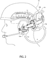
- the ear cup 14 may moved away from the helmet 18 by rotating the ear cup 14 relative to the second axis A2, then rotating the ear cup 14 about the first axis A1 (see the reverse of direction arrow R in Fig. 2 ) until the ear cup 14 is positioned over the user's ear and then releasing the lock using the release button 22 (see direction arrow B in Figs. 6 and 7 ) to bias the ear cup 14 around the user's ear (see direction arrow C in Figs. 6 and 7 ).
- friction in the hinge 20 and/or friction between hinge 20 and end 10b retains the arm 12 in the desired location following adjustment by the user.
- the friction force may sufficiently high to retain the ear cup 14 in normal operating conditions such as movement of the head while sufficiently low to allow the user to adjust the position of the ear cup 14 relative to the helmet 18 with one hand.
- the hinge 20 includes a locking mechanism to retain the hinge 20 in the desired angular position relative to axis A1.
- arm 12 is rotatable about axis A1 relative to second end 10b approximately 180 degrees.
- arm 12 is rotatable about axis A2 relative to second end 10b 360 degrees.
- arm 12 and/or hinge 20 includes a stop to limit the amount of rotation of arm 12 about axis A2 relative to second end 10b.
- a stop may be provided to limit the rotation of arm 12 about axis A2 relative to second end 10b when the ear cup 14 extends over a back surface 18a of the helmet 18.
Description
- The present invention generally relates to a pivot-arm assembly for a helmet mounted headset.
-
US8,166,575 discloses a protective head gear combination having a helmet and at least one ear defender secured on the helmet. The ear defender is secured to the helmet by means of a holding bracket which is hinged to allow the ear defender to pivot about a first axis and a second axis of rotation.US5,546,610 discloses a fastening system for adjustably holding a hearing-protection cap on a helmet. The fastening system comprises a holding strap that can be pivoted by means of a fastening device that allows the hearing-protection cap to be rotated about a first axis and a second axis in rotation. - In one embodiment there is a pivot-arm assembly for attaching an ear cup to a mounting feature on an exterior of a helmet, the pivot-arm assembly comprising: a mount configured to releasably couple to the mounting feature; an arm having a first end configured to couple to the ear cup and a second end; a hinge rotatable about a first axis and about a second axis, the hinge being coupled to the second end of the arm and disposed between the second end of the arm and the mount such that the first end of the arm is rotatable relative to the mount about the first axis and the first end of the arm is rotatable relative to the mount about the second axis; and a biasing member coupled to the arm and configured to spring bias the first end of the arm relative to the mount in a rotatable direction about the second axis of the hinge;
wherein the pivot-arm assembly further comprises a lock configured to releasably retain the first end of the arm in a predetermined rotational position relative to the second axis;
wherein the pivot-arm assembly further comprises a release configured to selectively release the lock. - In one embodiment, the lock includes a plate having a multi-lobed slot and a spring-biased protrusion extending through the multi-lobed slot, the protrusion being engageable with the multi-lobed slot to lock a rotational position of the first end of the arm relative to the second axis in a first position when the protrusion engages a first lobe of the multi-lobed slot and lock the rotational position of the first end of the arm relative to the second axis in a second position when the protrusion engages a second lobe of the multi-lobed slot. In one embodiment, the protrusion is engageable with the multi-lobed slot to lock a rotational position of the first end of the arm relative to the second axis in a third position when the protrusion engages a third lobe of the multi-lobed slot.
- In one embodiment, the multi-lobed slot is shaped and configured so that rotational movement of the first end of the arm about the second axis causes the lock to transition from the first position to the second position. In one embodiment, the multi-lobed slot is shaped and configured so that rotational movement of the first end about the second axis causes the lock to transition from the second position to the third position. In a further embodiment the release button is coupled to the protrusion, wherein depression of the release button urges the protrusion into the first position. In one embodiment, the lock and the hinge are surrounded by a common housing. In one embodiment, the lock is configured to releasably retain the first end of the arm in two or more predetermined angular positions relative to the second axis.
- In a further embodiment, the pivot-arm assembly includes the mounting feature coupled to the second end. In one embodiment, the mounting feature includes a dovetail groove with at least a portion of the dovetail groove positioned on the helmet behind the wearer's ear, the mount including a dovetail projection configured to mount in the dovetail groove. In one embodiment, the hinge is a first hinge, the pivot-arm assembly further comprising: a second hinge coupled to the first end of the arm. In one embodiment, the second hinge includes a gimbal attachment. In a further embodiment, the pivot-arm assembly includes the ear cup coupled to the first end. In one embodiment, the biasing member is coupled to the hinge. In one embodiment, the biasing member includes a torsion spring. In one embodiment, the arm has an adjustable telescoping length. In one embodiment, the first axis of the hinge is generally perpendicular to the second axis of the hinge. In one embodiment, the first end is freely rotatable about the first axis of the hinge. In one embodiment, the mount includes a dovetail projection.
- In another embodiment, there is a pivot-arm assembly for attaching an ear cup to a mounting feature of a helmet, the pivot-arm assembly comprising: an ear cup; and a mount configured to releasably couple to a mounting feature on the helmet; an arm having a first portion coupled to the ear cup, the arm having a second portion moveably coupled to the first portion to adjust a length of the arm; a hinge having a first part rotatable about a first axis and second part rotatable about a second axis, the first axis being generally perpendicular to the second axis, the first part of the hinge being coupled to the mount and the second part of the hinge being coupled to the second portion such that the first portion of the arm is rotatable relative to the mount about the first axis and the first portion of the arm is rotatable relative to the mount about the second axis, the second part of the hinge having a torsion spring coupled to the first portion of the arm and configured to spring bias the first portion of the arm relative to the mount in a rotatable direction about the second axis of the hinge, the second part of the hinge having a lock configured to releasably retain the first portion of the arm in a predetermined angular position relative to the second axis, the second part of the hinge having a release configured to selectively release the lock.
- In a further embodiment, the pivot-arm assembly includes a deployed position defined by when the mount is mounted to the mounting feature and the ear cup is biased against the wearer's head; a locked position defined by when the mount is mounted to the mounting feature, the lock retains the first portion of the arm in the predetermined angular position and the ear cup is positioned over the wearer's ear, the ear cup is spaced from the wearer's head; and a stowed position defined by when the mount is mounted to the mounting feature and the ear cup is positioned over a back portion of the helmet, the ear cup is biased against the back portion of the helmet.
- The following detailed description of embodiments of the pivot-arm assembly for a helmet mounted headset, will be better understood when read in conjunction with the appended drawings of an exemplary embodiment. It should be understood, however, that the invention is not limited to the precise arrangements and instrumentalities shown.
- In the drawings:
-
Fig. 1 is a side view of the helmet mounted headset in accordance with an exemplary embodiment of the present invention shown in the deployed position; -
Fig. 2 is a side view of the helmet mounted headset ofFig. 1 shown attached to a helmet in the deployed position or locked position and illustrating the movement to the stowed position; -
Fig. 3 is a side view of the helmet mounted headset ofFig. 1 shown in the stowed position; -
Fig. 4 is a side view of the helmet mounted headset ofFig. 1 illustrating the adjustability of the pivot-arm; -
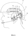
Fig. 5 is a side view of the helmet mounted headset ofFig. 1 illustrating actuation of the release button; -
Fig. 6 is a front perspective view of the helmet mounted headset ofFig. 1 shown in the deployed position and illustrating actuation of the release button and lateral movement of the ear cup; -
Fig. 7 is a front perspective view of the helmet mounted headset ofFig. 1 shown in the locked position and illustrating actuation of the release button and lateral movement of the ear cup; -
Fig. 8 is a rear perspective view of the helmet mounted headset shown inFig. 1 ; -
Fig. 9 is an enlarged top perspective view of the pivot-arm attached to the mounting rail shown inFig. 8 ; -
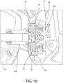
Fig. 10 is a first partially cut away side view of the hinge for the helmet mounted headset ofFig. 1 ; -
Fig. 11 is a second partially cut away side view of the hinge for the helmet mounted headset ofFig. 1 ; -
Fig. 12 is a perspective view of the helmet mounted headset ofFig. 1 ; -
Fig. 13 is a left side view of the helmet mounted headset ofFig. 1 ; -
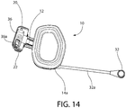
Fig. 14 is a right side view of the helmet mounted headset ofFig. 1 ; -
Fig. 15 is a front view of the helmet mounted headset ofFig. 1 ; -
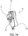
Fig. 16 is a rear view of the helmet mounted headset ofFig. 1 ; -
Fig. 17 is a bottom view of the helmet mounted headset shown inFig. 1 ; and -
Fig. 18 is a top view of the helmet mounted headset shown inFig. 1 . - Referring to the drawings in detail, wherein like reference numerals indicate like elements throughout, there is shown in
Figs. 1-18 a pivot-arm assembly for a helmet mounted headset, generally designated 10, in accordance with an exemplary embodiment of the present invention. The pivot-arm assembly 10 may also be generally referred to as a pivot-arm or a helmet mounted headset. - Ear accessories (e.g., communications devices integrated within a padded earphone or ear cup) can be critical in numerous helmet deployments; for example, the need for both protection and communication is particularly important in military, fire-fighter, rescue and similar activities. Ear accessories have been built into the helmet and worn separately beneath the helmet. An example of a helmet with built-in earphones is the present military helmet known as the Combat Vehicle Crew (CVC) helmet. Unfortunately, because the earphones add weight and do not function in dismounted operations, and cannot be removed from the CVC helmet, the vehicle crew members are issued two helmets--the CVC helmet and a standard infantry helmet. Other helmets having a mounted headset lack the functionality and performance of the helmet mounted headset disclosed herein.
- Referring to
Fig. 1 , the pivot-arm assembly 10 includes an arm orcoupling mechanism 12 configured to attach anear cup 14 to amounting feature 16 on the exterior of ahelmet 18. A second pivot-arm assembly (not shown) may be mounted to the other lateral side of thehelmet 18 in a mirrored configuration to the illustrated pivot-arm assembly 10. The pair of pivot-arm assemblies may be mirror configurations except for details of the ear cups such amicrophone 32. The pivot-arm assembly 10 may be provided to the consumer in pairs or individually. In some embodiments, theear cup 14 and/ormounting feature 16 are provided with the pivot-arm assembly 10 as a kit. In some embodiments, theear cup 14 and/or mountingfeature 16 are provided separately such that thearm 12 is initially unattached to anything. - In some embodiments, the pivot-
arm assembly 10 may allow for theheadset 10 to be mounted to ahelmet 18 and positioned against the wearer's ear during use (i.e., a deployed position, seeFig. 1 ) and stowed away from the wearer's ear when not in use (i.e., a stowed position, seeFigs. 3 and6 ). In one embodiment, the stowed position allows for a very low profile on thehelmet 18. In one embodiment, the ear cups 14 are not visible from a front view of the helmet (i.e., looking at the wearer head on) in the stowed position. In some embodiments, the pivot-arm assembly 10 may extend over but be spaced from the wearer's ear in one or more positions (i.e., a locked position or float position, seeFig. 7 ). - Referring to
Fig. 1 , thearm 12 has afirst end 10a and asecond end 10b, thefirst end 10a being coupled to theear cup 14 and the second end being releasably coupled to the mountingfeature 16. Thefirst end 10a may be releasably or fixed to theear cup 14. - In one embodiment, the
ear cup 14 is configured to restore "natural hearing" with the outside environment for improved situational awareness while at the same time providing for hearing protection. Theear cup 14 may be a circumaural ear cup. In one embodiment, theear cup 14 includes acushion 14a. In one embodiment,cushion 14a is configured to be contoured to match the geometry of the wearer's head and provide a better seal and proper attenuation. At least one of the ear cups 14 may include amicrophone 32. In one embodiment,ear cup 14 includes aboom arm 32a. Theboom arm 32a may be flexible such that the user can bendboom arm 32a and place themicrophone 32 a desired distance from the user's mouth. - Referring to
Fig. 6 , ahinge 20 is provided to position theear cup 14 relative to thehelmet 18 in a plurality of positions. Thehinge 20 is rotatable about a first axis A1 and about a second axis A2. Thehinge 20 may be coupled between thesecond end 10b or mount 36 (seeFig. 14 ) and the second end of thearm 12 such that thefirst end 10a of thearm 12 is rotatable relative to themount 36 about the first axis A1 and the first end of thearm 10a is rotatable relative to themount 36 about the second axis A2. In one embodiment, thefirst end 10a is spring biased in a rotatable direction (e.g., toward the wearer's ear) about the second axis A2 of thehinge 20. By providing thehinge 20 with at least two degrees of freedom and a spring bias in at least one direction, theear cup 14 may be held against the wearer's ear and easily moved out of the way to a float and/or stowed position using one hand. In some embodiments, theear cup 14 may be selectively biased against the wearer's ear in a deployed position and spaced from the wearer's ear in one or more float or locked positions. - Referring to
Fig. 1 , the pivot-arm assembly 10 may have a deployed position defined by when thesecond end 10b of the pivot-arm is mounted to the mountingfeature 16, thefirst end 10a is positioned proximate a wearer's ear and therelease button 22 is actuated, theear cup 14 is biased against the wearer's ear. In the deployed position, thecushion 14a may be pressed against the wearer's head when theear cup 14 is being used. - Referring to
Fig. 7 , the pivot-arm assembly 10 may have one or more locked positions defined by when thesecond end 10b is mounted to the mountingfeature 16, thefirst end 10a is positioned proximate a wearer's ear and a lock 30 (seeFig. 11 ) retains thefirst end 10a in the predetermined angular position, theear cup 14 is spaced from the wearer's ear. In the locked position, theear cup 14 may be used in certain circumstances (e.g., to allow for more access to outside noise or to relieve the biasing force against the wearer's head from thecushion 14a) and/or moved to the stowed position. In one embodiment, the pivot-arm assembly 10 includes two or more locked positions for spacing thecushion 14a from the ear in one of a plurality of distances. - Referring to
Fig. 3 , the pivot-arm assembly 10 may have a stowed position defined by when thesecond end 10b is mounted to the mountingfeature 16 and thefirst end 10a is positioned proximate aback portion 18a of thehelmet 18, theear cup 14 extends over theback portion 18a of thehelmet 18. - Referring to
Fig. 4 , thearm 12 may include two ormore segments arm 12 to another length L2 and fit the anatomy of the particular user. For example, a first person's ear may be spaced a different distance from the mountingfeature 16 for the same helmet worn by a second person. The two ormore segments arm 12 includes afirst segment 12a and asecond segment 12b. In one embodiment, thefirst segment 12a telescopically slides into thesecond segment 12b. In other embodiments, thesecond segment 12b slides into thesecond segment 12b or they are slidable in front or behind the other. - In one embodiment, the
first segment 12a is friction fit with thesecond segment 12b. This may allow for a user to adjust the length ofarm 12 with one hand when the pivot-arm assembly 10 is mounted to thehelmet 18. In one embodiment, thefirst segment 12a is friction fit with thesecond segment 12b such that to move thefirst segment 12a relative to thesecond segment 12b, a force of greater than approximately 1 lbF parallel to a linear axis of motion is required. In one embodiment, thefirst segment 12a and/or thesecond segment 12b includes indents and/or an audible click to indicate the length L1, L2 of thearm 12. In other embodiments, thefirst segment 12a andsecond segment 12b are adjustable via an attachment mechanism such as a worm gear and rack. - In one embodiment, the
first segment 12a and thesecond segment 12b are generally rigid. In other embodiments, thefirst segment 12a and thesecond segment 12b are flexible. Thearm 12 may have a curved shape in order to properly position theear cup 14 over the user's ear in the deployed position and allow for a streamlined configuration in the stowed position. Thefirst segment 12a and thesecond segment 12b may be comprised of different materials from one another. In one embodiment, thefirst segment 12a is comprised of metal and thesecond segment 12b is comprised of plastic. - Referring to
Figs. 6 and7 , thehinge 20 has two or more degrees of freedom. In one embodiment, hinge 20 has two degrees of rotational freedom. In one embodiment, hinge 20 is provided proximate thesecond end 10b of the pivot-arm assembly 10 close to the mountingfeature 16. In one embodiment, thehinge 20 extends over the mountingfeature 16 when the pivot-arm assembly is mounted to the mountingfeature 16. In one embodiment, thehinge 20 extends over a portion of thehelmet 12 when the pivot-arm assembly is mounted to the mountingfeature 16. Thehinge 20 may be configured to rotate thearm 12 relative to mount 36 or mountingfeature 16 about the first axis A1 to position theear cup 14 proximate a wearer's ear when in use and facilitate rotation of the ear cup to a stowed position behind the helmet when not in use. Thehinge 20 may also be configured to rotatearm 12 relative to mount 36 or mountingfeature 16 about a second axis A2 to move theear cup 14 toward and away from the wearer's ear. In one embodiment, the first axis A1 is generally perpendicular to the second axis A2. In one embodiment, the first axis A1 is not coplanar with the second axis A2. In other embodiments, the first axis A1 is coplanar with the second axis A2. - In one embodiment, the
hinge 20 has a first part rotatable about the first axis A1 and second part rotatable about the second axis A2. The first part of the hinge may coupled to the mount and the second part of thehinge 20 may be coupled to thesecond portion 12b of thearm 12. In one embodiment the first part of thehinge 20 is coupled to the second part of thehinge 20. In other embodiments, the first part of thehinge 20 is indirectly coupled to the second part of thehinge 20 by a spacer element. In some embodiments, the first and second parts of thehinge 20 are collectively referred to as a single hinge. - Referring to
Fig. 1 , the first end of thearm 12 may be coupled to theear cup 14 by asecond hinge 34. Thehinge 34 may be configured to allow theear cup 14 to pivot and/or rotate relative to thearm 12 and position theear cup 14 to the desired position relative to the wearer's ear. In one embodiment, hinge 34 is agimbal attachment 34. In one embodiment, thehinge 34 is configured to allow theear cup 14 to pivot up to approximately 5 degrees in any direction from a base plane normal to the hinge's 34 center axis. In one embodiment, thehinge 34 is configured to allow theear cup 14 to pivot up to approximately 10 degrees in any direction from a base plane normal to the hinge's 34 center axis. In one embodiment, thehinge 34 is configured to allow theear cup 14 to pivot up to approximately 15 degrees in any direction from a base plane normal to the hinge's 34 center axis. In one embodiment, thehinge 34 is configured to allow theear cup 14 to pivot up to approximately 20 degrees in any direction from a base plane normal to the hinge's 34 center axis. In one embodiment, thehinge 34 is configured to allow theear cup 14 to pivot up to approximately 20 degrees in any direction from a base plane normal to the hinge's 34 center axis. - The
hinge 34 may be configured to allow theear cup 14 to rotate about hinge's 34 center axis. In one embodiment, thehinge 34 is configured to allow theear cup 14 to rotate 360° about hinge's 34 center axis. Once moved to the desired position, thehinge 34 may be retained in place by friction. The friction force may sufficiently high to retain theear cup 14 in normal operating conditions such as movement of the head while sufficiently low to allow the user to adjust the position of theear cup 14 relative to thearm 12 with one hand. In other embodiments, thehinge 34 includes a locking mechanism to retain thehinge 34 in the desired position. - Referring to
Figs. 8 and9 , thesecond end 10b of the pivot-arm assembly 10 may be coupled to a mountingfeature 16. In one embodiment, pivot-arm assembly 10 is releasably coupled to the mountingfeature 16. In one embodiment, the mountingfeature 16 includes adovetail groove 16a. In one embodiment, the mountingfeature 16 is a rail (e.g., an Accessory Rail Connectors (ARC)) as disclosed inU.S. Patent No. 7,908,667 . In one embodiment, at least a portion of thedovetail groove 16a is positioned on thehelmet 18 behind the wearer's ear. In one embodiment, theheadset 10 attaches to the rear portion of the mounting features 16, leaving the top portion of the mountingfeature 16 free for mounting other accessories to the helmet such as lights, cameras, etc. Thesecond end 10b may include a mount 36 (seeFig. 14 ). - Referring to
Figs. 9 ,14 ,16 and17 , themount 36 may have a dovetail shape projection corresponding to the dovetail shape of thedovetail groove 16a of the mountingfeature 16. In one embodiment, themount 36 has parallel sides to allow for themount 36 to be slid along thedovetail groove 16a of the mountingfeature 16. Thesecond end 10b may further include alocking mechanism 36a. In one embodiment, thelocking mechanism 36a is a spring biased tab that retains themount 36 in the mountingfeature 16 when released and allows thesecond end 10b to be moved and/or removed from the mountingfeature 16 when depressed. In one embodiment, mount 36 is coupled to thehinge 20. In other embodiments, mount 36 is indirectly coupled to thehinge 20 by a spacer element. - The
hinge 20 may include a lock 30 (seeFig. 11 ) configured to releasably retain thefirst end 10a in a predetermined angular position relative to the second axis A2. In one embodiment, thelock 30 is configured to releasably retain thefirst end 10a in two or more predetermined angular positions relative to the second axis A2. The lock may include arelease button 22 configured to selectively release thelock 30. Therelease button 22 may extend along the second axis A2. In on embodiment, therelease button 22 extends downwardly from thehinge 20 when the pivot-arm assembly 10 is mounted to thehelmet 18 such that the user can release therelease button 22 with their thumb while grasping theear cup 14 with the remainder of their hand. In other embodiments, therelease button 22 includes a lever or a knob. - Referring to
Figs. 2 ,3 ,6 and7 , thehinge 20 may be spring biased toward the wearer's ear in the lateral direction (e.g., about the second axis A2) in order to keep theear cup 14 in the desired position relative to the wearer's ear. Thehinge 20 may be spring biased toward the wearer's ear such that theear cup 14 is held against the wearer's ear and is retained there by the spring force. In one embodiment, thehinge 20 includes alock 30 to releasebly retain theear cup 14 away from the wearer's ear two or more predetermined positions. Said another way, thelock 30 may be configured to retain thearm 12 in two or more angular positions relative to axis A2. Thehinge 20 may include arelease 22 configured to release thelock 30 when actuated. Thehinge 20 may allow for theear cup 14 to be rotated about second axis A2 a sufficient distance to clear the helmet edge when transitioning the pivot-arm assembly 10 from the locked position to the stowed position (see arrow R inFig. 2 ). In one embodiment,arm 12 is rotatable relative to the mountingfeature 16 approximately 180 degrees (seeFig. 2 ). In one embodiment,arm 12 is rotatable relative to mountingfeature 16 about axis A2 approximately 25 degrees from the deployed position to the first locked position. In one embodiment,arm 12 is rotatable relative to mountingfeature 16 about axis A2 approximately 15 degrees from the first position to the second locked position. - In one embodiment, there are three positions of the
arm 12 relative to themount 36 with theear cup 14 aligned with the wearer's ear. If the deployed position is considered the start position (0 degrees) then first click to a locked position of thearm 12 is 40 degrees from that, which is a first lock position or float position of theear cushion 14a just off the user's head. In the float position, theear cushion 14a may be touching the user depending on the user's head width, but there will be no sealing or ear protection, allowing the user to hear past the seal or theear cushion 14a). The next click position would be 20 degrees from the float position to the second locked position. This position puts theearcup 14 out further from the user to clear thehelmet 12 when stowing the pivot-arm assembly 10, so the user does not need to actively fight the spring pressure when transferring the pivot-arm assembly 10 to the stowed position. In one embodiment, there is an over-travel allowance for thearm 12 to be pulled another 5 degrees from the second locked position to help with rotation without a third locked position. In other embodiments, there are additional locked positions to position theearcup 14 in the desired position. - Referring to
Figs. 10 and11 , thehinge 20 may be spring biased by one or more torsion springs 24 that spring bias thearm 12 toward the user. Therelease 22 may include ashaft 22a. In one embodiment, therelease 22 includes abutton 22b on the end of theshaft 22a. Theshaft 22a may be positioned along the second axis A2. In one embodiment, theshaft 22a extends through the one or more torsion springs 24. Theshaft 22a of therelease button 22 may be spring biased downwardly by a biasingmember 28 such as a spring. Theshaft 22a may be coupled to aprotrusion 26 coupled to thearm 12. In one embodiment, theprotrusion 26 is configured to slide vertically with theshaft 22a but not translate horizontally or rotate. Theprotrusion 26 may extend through thelock 30. Thelock 30 may include a multi-lobed plate. Thelock 30 may include three or more slots orlobes protrusion 26. In one embodiment, the length of theslot protrusion 26 may move and therefore how far thearm 12 can rotate. For example, when theprotrusion 26 is in thefirst slot 30a, thearm 12 is free to rotate toward the user's head. In one embodiment, theear cup 14 abuts against the user's ear before the protrusion abuts against the end of thefirst slot 30a. - When the user grasps the
ear cup 14 and rotates theear cup 14 about the second axis A2, thelock 30 is rotated relative toprotrusion 26 until the springbiased shaft 22a slides the protrusion 26into thesecond slot 30b. Thesecond slot 30b may be configured such that thearm 12 is retained by thesecond slot 30b rather than the user's ear. Once retained by thesecond slot 30b, theear cup 14 is spaced from the user's ear. Theear cup 14 may be further rotated about the second axis A2 such that thelock 30 is rotated until the protrusion is retain in thethird slot 30c. By pushing therelease button 22, theprotrusion 26 is moved from thesecond slot 30b or thethird slot 30c into thefirst slot 30a allowing theear cup 14 to contact the user's ear. Alternatively, when thearm 12 is retained by thethird slot 30c, thearm 12 can be rotated about the first axis A1 and into the stowed position. Once in the stowed position, therelease button 22 may be actuated to spring bias theear cup 14 against the back of thehelmet 18. In other embodiments, thelock 30 includes one or two slots to retain thearm 12 in a single locked position. In other embodiments, thelock 30 includes four or more slots to allow for additional positioning of theear cup 14 relative to the user and/orhelmet 18. - Referring to
Figs. 2 ,6 and7 , thefirst end 10a may be freely rotatable about the first axis A1 of thehinge 20 from the locked position to the stowed position. In one embodiment, thefirst end 10a is retained in place relative to axis A1 by the spring bias ofhinge 20 moving the ear cup against the user in the deployed position and against the helmet in the stowed position. Thelock 30 may be released in the stowed position such that theear cup 14 is urged against the surface of thehelmet 18 to retain theear cup 14 in the stowed position. In one embodiment, theear cup 14 does not clear thehelmet 18 in the locked position so that theear cup 14 must be further rotated against the biasing force about axis A2 to move theear cup 14 to the stowed position, the biasing force urging theear cup 18 against theback surface 18a of thehelmet 18. When the user is ready to deploy theear cup 14, theear cup 14 may moved away from thehelmet 18 by rotating theear cup 14 relative to the second axis A2, then rotating theear cup 14 about the first axis A1 (see the reverse of direction arrow R inFig. 2 ) until theear cup 14 is positioned over the user's ear and then releasing the lock using the release button 22 (see direction arrow B inFigs. 6 and7 ) to bias theear cup 14 around the user's ear (see direction arrow C inFigs. 6 and7 ). - In one embodiment, friction in the
hinge 20 and/or friction betweenhinge 20 andend 10b retains thearm 12 in the desired location following adjustment by the user. The friction force may sufficiently high to retain theear cup 14 in normal operating conditions such as movement of the head while sufficiently low to allow the user to adjust the position of theear cup 14 relative to thehelmet 18 with one hand. In other embodiments, thehinge 20 includes a locking mechanism to retain thehinge 20 in the desired angular position relative to axis A1. In one embodiment,arm 12 is rotatable about axis A1 relative tosecond end 10b approximately 180 degrees. In oneembodiment arm 12 is rotatable about axis A2 relative tosecond end 10b 360 degrees. In other embodiments,arm 12 and/or hinge 20 includes a stop to limit the amount of rotation ofarm 12 about axis A2 relative tosecond end 10b. For example, a stop may be provided to limit the rotation ofarm 12 about axis A2 relative tosecond end 10b when theear cup 14 extends over aback surface 18a of thehelmet 18. - It will be appreciated by those skilled in the art that changes could be made to the exemplary embodiments shown and described above without departing from the scope of the invention as defined by the claims. It is understood, therefore, that this invention is not limited to the exemplary embodiments shown and described, but it is intended to cover modifications within scope of the present invention as defined by the claims. For example, specific features of the exemplary embodiments may or may not be part of the claimed invention and various features of the disclosed embodiments may be combined. Unless specifically set forth herein, the terms "a", "an" and "the" are not limited to one element but instead should be read as meaning "at least one".
- It is to be understood that at least some of the figures and descriptions of the invention have been simplified to focus on elements that are relevant for a clear understanding of the invention, while eliminating, for purposes of clarity, other elements that those of ordinary skill in the art will appreciate may also comprise a portion of the invention. However, because such elements are well known in the art, and because they do not necessarily facilitate a better understanding of the invention, a description of such elements is not provided herein.
Claims (15)
- A pivot-arm assembly (10) for attaching an ear cup (14) to a mounting feature (16) on an exterior of a helmet (18), the pivot-arm assembly comprising:a mount configured to releasably couple to the mounting feature (16);an arm (12) having a first end (10a) configured to couple to the ear cup (14) and a second end (10b);a hinge (20) rotatable about a first axis (A1) and about a second axis (A2), the hinge being coupled to the second end (10b) of the arm (12) and disposed between the arm and the mount such that the first end (10a) of the arm (12) is rotatable relative to the mount about the first axis (A1) and the first end (10a) of the arm (12) is rotatable relative to the mount about the second axis (A2); and
a biasing member (24) coupled to the arm and configured to spring bias the first end (10a) of the arm (12) relative to the mount in a rotatable direction about the second axis (A2) of the hinge (20);characterized in that the pivot-arm assembly further comprises a lock (30) configured to releasably retain the first end (10a) of the arm (12) in a predetermined rotational position relative to the second axis (A2);wherein the pivot-arm assembly further comprises a release configured to selectively release the lock. - The pivot-arm assembly of claim 1, wherein the release comprises a release button (22); optionally wherein the release button (22) extends downwardly from the hinge (20) when the pivot-arm assembly (10) is mounted to the helmet (18) such that the user can release the release button (22) with their thumb whilst grasping the ear cup (14) with the remainder of their hand.
- The pivot-arm assembly of claim 2, wherein the lock (30) includes a plate having a multi-lobed slot and a spring-biased protrusion (26) extending through the multi-lobed slot, the protrusion (26) being engageable with the multi-lobed slot to lock a rotational position of the first end (10a) of the arm (12) relative to the second axis (A2) in a first position when the protrusion (26) engages a first lobe (30a) of the multi-lobed slot and lock the rotational position of the first end (10a) of the arm (12) relative to the second axis (A2) in a second position when the protrusion (26) engages a second lobe (30b) of the multi-lobed slot.
- The pivot-arm assembly of claim 3, wherein the protrusion (26) is engageable with the multi-lobed slot to lock a rotational position of the first end (10a) of the arm (12) relative to the second axis (A2) in a third position when the protrusion (26) engages a third lobe (30c) of the multi-lobed slot.
- The pivot-arm assembly of claim 3, wherein the multi-lobed slot is shaped and configured so that rotational movement of the first end (10a) of the arm (12) about the second axis (A2) causes the lock (30) to transition from the first position to the second position.
- The pivot-arm assembly of claim 5, wherein the multi-lobed slot is shaped and configured so that rotational movement of the first end (10a) about the second axis (A2) causes the lock (30) to transition from the second position to the third position.
- The pivot-arm assembly of claim 3 wherein the release is coupled to the protrusion, wherein depression of the release urges the protrusion into the first position.
- The pivot-arm assembly of claim 1, wherein the lock (30) and the hinge (20) are surrounded by a common housing; or:
wherein the lock (30) is configured to releasably retain the first end (10a) of the arm (12) in two or more predetermined angular positions relative to the second axis (A2). - The pivot-arm assembly of claim 1 further comprising:
the mounting feature (16) coupled to the second end (10b); and optionally:
wherein the mounting feature (16) includes a dovetail groove (10b) with at least a portion of the dovetail groove positioned on the helmet (18) behind the wearer's ear, the mount including a dovetail projection configured to mount in the dovetail groove (16a). - The pivot-arm assembly of claim 1, wherein the hinge (20) is a first hinge, the pivot-arm assembly further comprising:
a second hinge (34) coupled to the first end (10a) of the arm (12). - The pivot-arm assembly of claim 10, wherein the second hinge (34) includes a gimbal attachment.
- The pivot-arm assembly of claim 1 further comprising:
the ear cup (14) coupled to the first end (10a); or:
wherein the biasing member (24) is coupled to the hinge (20). - The pivot-arm assembly of claim 1, wherein the biasing member (24) includes a torsion spring.
- The pivot-arm assembly of claim 1, wherein the arm (12) has an adjustable telescoping length; or:
wherein the first axis (A1) of the hinge (20) is generally perpendicular to the second axis (A2) of the hinge (20). - The pivot-arm assembly of claim 1, wherein the mount includes a dovetail projection.
Applications Claiming Priority (2)
| Application Number | Priority Date | Filing Date | Title |
|---|---|---|---|
| US201461927204P | 2014-01-14 | 2014-01-14 | |
| PCT/US2015/011159 WO2015108854A1 (en) | 2014-01-14 | 2015-01-13 | Pivot-arm assembly for a helmet mounted headset |
Publications (3)
| Publication Number | Publication Date |
|---|---|
| EP3094199A1 EP3094199A1 (en) | 2016-11-23 |
| EP3094199A4 EP3094199A4 (en) | 2017-08-30 |
| EP3094199B1 true EP3094199B1 (en) | 2019-07-24 |
Family
ID=53543358
Family Applications (1)
| Application Number | Title | Priority Date | Filing Date |
|---|---|---|---|
| EP15737006.5A Active EP3094199B1 (en) | 2014-01-14 | 2015-01-13 | Pivot-arm assembly for a helmet mounted headset |
Country Status (4)
| Country | Link |
|---|---|
| US (2) | US10617168B2 (en) |
| EP (1) | EP3094199B1 (en) |
| DK (1) | DK3094199T3 (en) |
| WO (1) | WO2015108854A1 (en) |
Cited By (1)
| Publication number | Priority date | Publication date | Assignee | Title |
|---|---|---|---|---|
| US11089831B1 (en) | 2020-10-23 | 2021-08-17 | DoubleThree, LLC | Incrementally adjustable and pivotable semi-rigid retention strap for a helmet |
Families Citing this family (36)
| Publication number | Priority date | Publication date | Assignee | Title |
|---|---|---|---|---|
| USD750846S1 (en) * | 2006-02-09 | 2016-03-01 | Artisent, Llc | Helmet mounted rail |
| KR102386680B1 (en) * | 2014-05-02 | 2022-04-14 | 쓰리엠 이노베이티브 프로퍼티즈 캄파니 | Ear muff attachment having dual axis of rotation |
| US10667029B2 (en) * | 2015-07-16 | 2020-05-26 | Voyetra Turtle Beach, Inc. | Headset with internal gimbal |
| US10779604B2 (en) * | 2015-11-30 | 2020-09-22 | Galvion Ltd. | Earphone and helmet with earphone |
| DE102016100086A1 (en) | 2016-01-04 | 2017-07-06 | Pfanner Schutzbekleidung Gmbh | Earmuffs, communication system and safety helmet |
| US11323793B2 (en) | 2016-09-23 | 2022-05-03 | Apple Inc. | Synchronized telescoping headphones |
| CN110062307B (en) * | 2016-09-23 | 2021-12-07 | 苹果公司 | Low spring rate band |
| US10945076B2 (en) | 2016-09-23 | 2021-03-09 | Apple Inc. | Low spring-rate band |
| US20180168270A1 (en) * | 2016-12-21 | 2018-06-21 | Safariland, Llc | Rail Connector For Earcup Suspension Assembly |
| US10393312B2 (en) | 2016-12-23 | 2019-08-27 | Realwear, Inc. | Articulating components for a head-mounted display |
| US11507216B2 (en) | 2016-12-23 | 2022-11-22 | Realwear, Inc. | Customizing user interfaces of binary applications |
| US11099716B2 (en) | 2016-12-23 | 2021-08-24 | Realwear, Inc. | Context based content navigation for wearable display |
| US10620910B2 (en) | 2016-12-23 | 2020-04-14 | Realwear, Inc. | Hands-free navigation of touch-based operating systems |
| US10437070B2 (en) | 2016-12-23 | 2019-10-08 | Realwear, Inc. | Interchangeable optics for a head-mounted display |
| US10365493B2 (en) * | 2016-12-23 | 2019-07-30 | Realwear, Incorporated | Modular components for a head-mounted display |
| US10936872B2 (en) | 2016-12-23 | 2021-03-02 | Realwear, Inc. | Hands-free contextually aware object interaction for wearable display |
| US20190008228A1 (en) * | 2016-12-30 | 2019-01-10 | David Francis Ramey | Integrated non-conflicting headgear platform system and method |
| US10959473B2 (en) * | 2017-01-10 | 2021-03-30 | Hmount Ltd | Plastic helmet mounting assembly |
| IL250044B (en) * | 2017-01-10 | 2019-05-30 | Shlomo Chen Itay | Plastic helmet mounting assembly |
| US10582736B2 (en) * | 2017-01-16 | 2020-03-10 | Safariland, Llc | Wireform attachment mechanism |
| WO2018148705A1 (en) * | 2017-02-13 | 2018-08-16 | Otto Engineering, Inc. | Headset mounts |
| CN207115267U (en) * | 2017-07-25 | 2018-03-16 | 深圳市大疆创新科技有限公司 | Wear display device |
| CN111316664A (en) | 2017-11-20 | 2020-06-19 | 苹果公司 | Earphone set |
| USD866084S1 (en) | 2018-05-18 | 2019-11-05 | Gentex Corporation | Headset mount arm |
| KR102529396B1 (en) | 2018-05-18 | 2023-05-04 | 젠텍스코오포레이션 | Headsets and Headset Coupling Systems |
| USD868741S1 (en) | 2018-05-18 | 2019-12-03 | Gentex Corporation | Headset accessory attachment |
| USD864901S1 (en) | 2018-05-18 | 2019-10-29 | Gentex Corporation | Headset |
| US10819886B2 (en) * | 2018-11-13 | 2020-10-27 | Twentieth Century Fox Film Corporation | Systems, methods and apparatuses for film virtual production |
| US10912344B2 (en) * | 2018-12-03 | 2021-02-09 | Msa Technology, Llc | Helmet with accessory attachment rail |
| USD889435S1 (en) * | 2019-02-18 | 2020-07-07 | Trent Zimmer | Headset accessory adapter |
| CN109965435A (en) * | 2019-03-14 | 2019-07-05 | 中科声华(苏州)科技有限公司 | A kind of connector that earphone is connected to the helmet |
| WO2020230102A1 (en) * | 2019-05-16 | 2020-11-19 | Locatelli S.P.A. | Protective helmet |
| US11213089B2 (en) | 2019-06-04 | 2022-01-04 | Msa Technology, Llc | Protective helmet with face protection shield and linkage mechanism |
| CN111202297B (en) * | 2020-03-02 | 2022-08-30 | 阜南县百帽王帽业有限公司 | Bluetooth cap is dressed to intelligence convenient to adjust |
| USD967549S1 (en) * | 2020-03-17 | 2022-10-18 | Trent Zimmer | Platform adapter |
| USD900407S1 (en) | 2020-05-22 | 2020-10-27 | Gentex Corporation | Helmet accessory mounting system |
Family Cites Families (20)
| Publication number | Priority date | Publication date | Assignee | Title |
|---|---|---|---|---|
| US3430261A (en) * | 1967-03-01 | 1969-03-04 | Air Reduction | Sound attenuator attachment for a protective helmet |
| SE352527B (en) * | 1970-03-19 | 1973-01-08 | B Loennstedt | |
| US4069512A (en) * | 1975-05-12 | 1978-01-24 | Tore Georg Palmaer | Locating device for ear-muffs on helmets |
| NO136693C (en) * | 1976-03-10 | 1977-10-26 | Erik Boettger | DEVICE WITH HELMET WITH WELL BELLS |
| US4109320A (en) * | 1977-06-10 | 1978-08-29 | Sellstrom Manufacturing Company | Attaching assembly |
| US4347631A (en) * | 1980-07-18 | 1982-09-07 | Norton Company | Ear muff accessory for safety hard hat |
| US4391000A (en) * | 1982-03-09 | 1983-07-05 | Loennstedt B G | Ear muff mounting device |
| JPS6155030A (en) * | 1984-08-23 | 1986-03-19 | Konishiroku Photo Ind Co Ltd | Sheet type object containing magazine |
| JPH02405Y2 (en) * | 1984-09-14 | 1990-01-08 | ||
| US5339464A (en) * | 1992-07-13 | 1994-08-23 | Litton Systems, Inc. | Universal adapter for night vision system |
| DE59406401D1 (en) * | 1993-09-30 | 1998-08-13 | Artilux Herzig Ag | Fastening system for a face shield and / or ear muffs on a work helmet |
| US6115846A (en) * | 1998-11-30 | 2000-09-12 | Truesdale; Max T | Headgear combined with a fan, electronic communication device and binoculars |
| JP2002142812A (en) * | 2000-11-13 | 2002-05-21 | Seiko Instruments Inc | Hinge unit for mounting band |
| US7908667B2 (en) | 2005-06-17 | 2011-03-22 | Artisent, Inc. | Mounting system for accessories on a safety helmet |
| US9072328B2 (en) * | 2005-06-17 | 2015-07-07 | Artisent, Llc | Hinged attachment of headgear to a helmet |
| DE102006040555A1 (en) * | 2006-08-30 | 2008-03-06 | Andreas Stihl Ag & Co. Kg | Protective headgear combination |
| US20120002046A1 (en) * | 2010-06-30 | 2012-01-05 | Raytheon Company | Flip-Up Hands-Free Display Mount |
| DE102010026997A1 (en) * | 2010-07-13 | 2012-01-19 | Anton Pfanner | Hearing protection for attachment to a protective helmet, in particular for forestry workers |
| US9631899B2 (en) * | 2011-03-14 | 2017-04-25 | Revision Military S.A.R.L. | Ballistic and impact protective military helmet assembly |
| US9572388B2 (en) * | 2014-01-30 | 2017-02-21 | Niterider Technical Lighting & Video Systems, Inc. | Helmet mount |
-
2015
- 2015-01-13 US US15/108,358 patent/US10617168B2/en active Active
- 2015-01-13 DK DK15737006.5T patent/DK3094199T3/en active
- 2015-01-13 WO PCT/US2015/011159 patent/WO2015108854A1/en active Application Filing
- 2015-01-13 EP EP15737006.5A patent/EP3094199B1/en active Active
-
2020
- 2020-03-05 US US16/810,170 patent/US20200196698A1/en active Pending
Non-Patent Citations (1)
| Title |
|---|
| None * |
Cited By (1)
| Publication number | Priority date | Publication date | Assignee | Title |
|---|---|---|---|---|
| US11089831B1 (en) | 2020-10-23 | 2021-08-17 | DoubleThree, LLC | Incrementally adjustable and pivotable semi-rigid retention strap for a helmet |
Also Published As
| Publication number | Publication date |
|---|---|
| DK3094199T3 (en) | 2019-09-30 |
| EP3094199A4 (en) | 2017-08-30 |
| US20160324248A1 (en) | 2016-11-10 |
| US20200196698A1 (en) | 2020-06-25 |
| EP3094199A1 (en) | 2016-11-23 |
| US10617168B2 (en) | 2020-04-14 |
| WO2015108854A1 (en) | 2015-07-23 |
Similar Documents
| Publication | Publication Date | Title |
|---|---|---|
| US20200196698A1 (en) | Pivot-Arm Assembly for a Helmet Mounted Headset | |
| US10660224B2 (en) | Head-mounted display device | |
| EP3982187B1 (en) | Head mount display support and head mount display | |
| EP2568836B1 (en) | Headgear support device having front-back adjustment | |
| EP2328529B1 (en) | Ear muff style ear protector devices | |
| JP6041803B2 (en) | Face protector attached to protective helmet | |
| US11337484B2 (en) | Headset and headset coupling system | |
| US8621664B2 (en) | Combination headgear and eye protection system | |
| AU2015253572B2 (en) | Ear muff attachment having dual axis of rotation | |
| US10278867B2 (en) | Helmet assemblies with flip-type welding visors | |
| NZ546880A (en) | Protective helmet | |
| EP2457459B1 (en) | A protective helmet with a head-width adjusting device adjustable from the exterior | |
| US20060236438A1 (en) | Drop-down eye protection for safety helmets | |
| JPWO2020161882A5 (en) | ||
| GB2583777A (en) | A virtual reality headset mount | |
| AU2011101018A4 (en) | Helmet Brim | |
| JP2019047217A (en) | Head-mounted display device |
Legal Events
| Date | Code | Title | Description |
|---|---|---|---|
| PUAI | Public reference made under article 153(3) epc to a published international application that has entered the european phase |
Free format text: ORIGINAL CODE: 0009012 |
|
| 17P | Request for examination filed |
Effective date: 20160727 |
|
| AK | Designated contracting states |
Kind code of ref document: A1 Designated state(s): AL AT BE BG CH CY CZ DE DK EE ES FI FR GB GR HR HU IE IS IT LI LT LU LV MC MK MT NL NO PL PT RO RS SE SI SK SM TR |
|
| AX | Request for extension of the european patent |
Extension state: BA ME |
|
| DAX | Request for extension of the european patent (deleted) | ||
| REG | Reference to a national code |
Ref country code: DE Ref legal event code: R079 Ref document number: 602015034305 Country of ref document: DE Free format text: PREVIOUS MAIN CLASS: A42B0003000000 Ipc: A42B0003300000 |
|
| A4 | Supplementary search report drawn up and despatched |
Effective date: 20170728 |
|
| RIC1 | Information provided on ipc code assigned before grant |
Ipc: A42B 3/30 20060101AFI20170724BHEP Ipc: A42B 3/16 20060101ALI20170724BHEP |
|
| GRAP | Despatch of communication of intention to grant a patent |
Free format text: ORIGINAL CODE: EPIDOSNIGR1 |
|
| STAA | Information on the status of an ep patent application or granted ep patent |
Free format text: STATUS: GRANT OF PATENT IS INTENDED |
|
| INTG | Intention to grant announced |
Effective date: 20180820 |
|
| GRAJ | Information related to disapproval of communication of intention to grant by the applicant or resumption of examination proceedings by the epo deleted |
Free format text: ORIGINAL CODE: EPIDOSDIGR1 |
|
| STAA | Information on the status of an ep patent application or granted ep patent |
Free format text: STATUS: REQUEST FOR EXAMINATION WAS MADE |
|
| GRAP | Despatch of communication of intention to grant a patent |
Free format text: ORIGINAL CODE: EPIDOSNIGR1 |
|
| STAA | Information on the status of an ep patent application or granted ep patent |
Free format text: STATUS: GRANT OF PATENT IS INTENDED |
|
| INTG | Intention to grant announced |
Effective date: 20190301 |
|
| GRAS | Grant fee paid |
Free format text: ORIGINAL CODE: EPIDOSNIGR3 |
|
| GRAA | (expected) grant |
Free format text: ORIGINAL CODE: 0009210 |
|
| STAA | Information on the status of an ep patent application or granted ep patent |
Free format text: STATUS: THE PATENT HAS BEEN GRANTED |
|
| RAP1 | Party data changed (applicant data changed or rights of an application transferred) |
Owner name: GENTEX CORPORATION |
|
| AK | Designated contracting states |
Kind code of ref document: B1 Designated state(s): AL AT BE BG CH CY CZ DE DK EE ES FI FR GB GR HR HU IE IS IT LI LT LU LV MC MK MT NL NO PL PT RO RS SE SI SK SM TR |
|
| REG | Reference to a national code |
Ref country code: GB Ref legal event code: FG4D |
|
| REG | Reference to a national code |
Ref country code: CH Ref legal event code: EP |
|
| REG | Reference to a national code |
Ref country code: DE Ref legal event code: R096 Ref document number: 602015034305 Country of ref document: DE |
|
| REG | Reference to a national code |
Ref country code: AT Ref legal event code: REF Ref document number: 1157116 Country of ref document: AT Kind code of ref document: T Effective date: 20190815 |
|
| REG | Reference to a national code |
Ref country code: IE Ref legal event code: FG4D |
|
| REG | Reference to a national code |
Ref country code: NL Ref legal event code: FP |
|
| REG | Reference to a national code |
Ref country code: CH Ref legal event code: NV Representative=s name: KIRKER AND CIE S.A., CH |
|
| REG | Reference to a national code |
Ref country code: DK Ref legal event code: T3 Effective date: 20190927 |
|
| REG | Reference to a national code |
Ref country code: SE Ref legal event code: TRGR |
|
| REG | Reference to a national code |
Ref country code: NO Ref legal event code: T2 Effective date: 20190724 |
|
| REG | Reference to a national code |
Ref country code: LT Ref legal event code: MG4D |
|
| PG25 | Lapsed in a contracting state [announced via postgrant information from national office to epo] |
Ref country code: HR Free format text: LAPSE BECAUSE OF FAILURE TO SUBMIT A TRANSLATION OF THE DESCRIPTION OR TO PAY THE FEE WITHIN THE PRESCRIBED TIME-LIMIT Effective date: 20190724 Ref country code: BG Free format text: LAPSE BECAUSE OF FAILURE TO SUBMIT A TRANSLATION OF THE DESCRIPTION OR TO PAY THE FEE WITHIN THE PRESCRIBED TIME-LIMIT Effective date: 20191024 Ref country code: PT Free format text: LAPSE BECAUSE OF FAILURE TO SUBMIT A TRANSLATION OF THE DESCRIPTION OR TO PAY THE FEE WITHIN THE PRESCRIBED TIME-LIMIT Effective date: 20191125 Ref country code: LT Free format text: LAPSE BECAUSE OF FAILURE TO SUBMIT A TRANSLATION OF THE DESCRIPTION OR TO PAY THE FEE WITHIN THE PRESCRIBED TIME-LIMIT Effective date: 20190724 Ref country code: FI Free format text: LAPSE BECAUSE OF FAILURE TO SUBMIT A TRANSLATION OF THE DESCRIPTION OR TO PAY THE FEE WITHIN THE PRESCRIBED TIME-LIMIT Effective date: 20190724 |
|
| PG25 | Lapsed in a contracting state [announced via postgrant information from national office to epo] |
Ref country code: RS Free format text: LAPSE BECAUSE OF FAILURE TO SUBMIT A TRANSLATION OF THE DESCRIPTION OR TO PAY THE FEE WITHIN THE PRESCRIBED TIME-LIMIT Effective date: 20190724 Ref country code: IS Free format text: LAPSE BECAUSE OF FAILURE TO SUBMIT A TRANSLATION OF THE DESCRIPTION OR TO PAY THE FEE WITHIN THE PRESCRIBED TIME-LIMIT Effective date: 20191124 Ref country code: ES Free format text: LAPSE BECAUSE OF FAILURE TO SUBMIT A TRANSLATION OF THE DESCRIPTION OR TO PAY THE FEE WITHIN THE PRESCRIBED TIME-LIMIT Effective date: 20190724 Ref country code: GR Free format text: LAPSE BECAUSE OF FAILURE TO SUBMIT A TRANSLATION OF THE DESCRIPTION OR TO PAY THE FEE WITHIN THE PRESCRIBED TIME-LIMIT Effective date: 20191025 Ref country code: LV Free format text: LAPSE BECAUSE OF FAILURE TO SUBMIT A TRANSLATION OF THE DESCRIPTION OR TO PAY THE FEE WITHIN THE PRESCRIBED TIME-LIMIT Effective date: 20190724 Ref country code: AL Free format text: LAPSE BECAUSE OF FAILURE TO SUBMIT A TRANSLATION OF THE DESCRIPTION OR TO PAY THE FEE WITHIN THE PRESCRIBED TIME-LIMIT Effective date: 20190724 |
|
| PG25 | Lapsed in a contracting state [announced via postgrant information from national office to epo] |
Ref country code: PL Free format text: LAPSE BECAUSE OF FAILURE TO SUBMIT A TRANSLATION OF THE DESCRIPTION OR TO PAY THE FEE WITHIN THE PRESCRIBED TIME-LIMIT Effective date: 20190724 Ref country code: EE Free format text: LAPSE BECAUSE OF FAILURE TO SUBMIT A TRANSLATION OF THE DESCRIPTION OR TO PAY THE FEE WITHIN THE PRESCRIBED TIME-LIMIT Effective date: 20190724 Ref country code: RO Free format text: LAPSE BECAUSE OF FAILURE TO SUBMIT A TRANSLATION OF THE DESCRIPTION OR TO PAY THE FEE WITHIN THE PRESCRIBED TIME-LIMIT Effective date: 20190724 |
|
| PG25 | Lapsed in a contracting state [announced via postgrant information from national office to epo] |
Ref country code: SM Free format text: LAPSE BECAUSE OF FAILURE TO SUBMIT A TRANSLATION OF THE DESCRIPTION OR TO PAY THE FEE WITHIN THE PRESCRIBED TIME-LIMIT Effective date: 20190724 Ref country code: IS Free format text: LAPSE BECAUSE OF FAILURE TO SUBMIT A TRANSLATION OF THE DESCRIPTION OR TO PAY THE FEE WITHIN THE PRESCRIBED TIME-LIMIT Effective date: 20200224 Ref country code: SK Free format text: LAPSE BECAUSE OF FAILURE TO SUBMIT A TRANSLATION OF THE DESCRIPTION OR TO PAY THE FEE WITHIN THE PRESCRIBED TIME-LIMIT Effective date: 20190724 Ref country code: CZ Free format text: LAPSE BECAUSE OF FAILURE TO SUBMIT A TRANSLATION OF THE DESCRIPTION OR TO PAY THE FEE WITHIN THE PRESCRIBED TIME-LIMIT Effective date: 20190724 |
|
| REG | Reference to a national code |
Ref country code: DE Ref legal event code: R097 Ref document number: 602015034305 Country of ref document: DE |
|
| PLBE | No opposition filed within time limit |
Free format text: ORIGINAL CODE: 0009261 |
|
| STAA | Information on the status of an ep patent application or granted ep patent |
Free format text: STATUS: NO OPPOSITION FILED WITHIN TIME LIMIT |
|
| REG | Reference to a national code |
Ref country code: AT Ref legal event code: UEP Ref document number: 1157116 Country of ref document: AT Kind code of ref document: T Effective date: 20190724 |
|
| PG2D | Information on lapse in contracting state deleted |
Ref country code: IS |
|
| 26N | No opposition filed |
Effective date: 20200603 |
|
| PG25 | Lapsed in a contracting state [announced via postgrant information from national office to epo] |
Ref country code: SI Free format text: LAPSE BECAUSE OF FAILURE TO SUBMIT A TRANSLATION OF THE DESCRIPTION OR TO PAY THE FEE WITHIN THE PRESCRIBED TIME-LIMIT Effective date: 20190724 Ref country code: MC Free format text: LAPSE BECAUSE OF FAILURE TO SUBMIT A TRANSLATION OF THE DESCRIPTION OR TO PAY THE FEE WITHIN THE PRESCRIBED TIME-LIMIT Effective date: 20190724 |
|
| PG25 | Lapsed in a contracting state [announced via postgrant information from national office to epo] |
Ref country code: LU Free format text: LAPSE BECAUSE OF NON-PAYMENT OF DUE FEES Effective date: 20200113 |
|
| PG25 | Lapsed in a contracting state [announced via postgrant information from national office to epo] |
Ref country code: IE Free format text: LAPSE BECAUSE OF NON-PAYMENT OF DUE FEES Effective date: 20200113 |
|
| PG25 | Lapsed in a contracting state [announced via postgrant information from national office to epo] |
Ref country code: MT Free format text: LAPSE BECAUSE OF FAILURE TO SUBMIT A TRANSLATION OF THE DESCRIPTION OR TO PAY THE FEE WITHIN THE PRESCRIBED TIME-LIMIT Effective date: 20190724 Ref country code: CY Free format text: LAPSE BECAUSE OF FAILURE TO SUBMIT A TRANSLATION OF THE DESCRIPTION OR TO PAY THE FEE WITHIN THE PRESCRIBED TIME-LIMIT Effective date: 20190724 |
|
| PG25 | Lapsed in a contracting state [announced via postgrant information from national office to epo] |
Ref country code: MK Free format text: LAPSE BECAUSE OF FAILURE TO SUBMIT A TRANSLATION OF THE DESCRIPTION OR TO PAY THE FEE WITHIN THE PRESCRIBED TIME-LIMIT Effective date: 20190724 |
|
| PGFP | Annual fee paid to national office [announced via postgrant information from national office to epo] |
Ref country code: BE Payment date: 20221216 Year of fee payment: 9 |
|
| REG | Reference to a national code |
Ref country code: NO Ref legal event code: CREP |
|
| PGFP | Annual fee paid to national office [announced via postgrant information from national office to epo] |
Ref country code: NO Payment date: 20230110 Year of fee payment: 9 Ref country code: DK Payment date: 20230111 Year of fee payment: 9 Ref country code: CH Payment date: 20230106 Year of fee payment: 9 Ref country code: AT Payment date: 20221228 Year of fee payment: 9 |
|
| PGFP | Annual fee paid to national office [announced via postgrant information from national office to epo] |
Ref country code: TR Payment date: 20230112 Year of fee payment: 9 Ref country code: IT Payment date: 20221213 Year of fee payment: 9 Ref country code: DE Payment date: 20221130 Year of fee payment: 9 |
|
| P01 | Opt-out of the competence of the unified patent court (upc) registered |
Effective date: 20230509 |
|
| PGFP | Annual fee paid to national office [announced via postgrant information from national office to epo] |
Ref country code: GB Payment date: 20231130 Year of fee payment: 10 |
|
| PGFP | Annual fee paid to national office [announced via postgrant information from national office to epo] |
Ref country code: SE Payment date: 20231213 Year of fee payment: 10 Ref country code: NL Payment date: 20231215 Year of fee payment: 10 Ref country code: FR Payment date: 20231212 Year of fee payment: 10 |
|
| PGFP | Annual fee paid to national office [announced via postgrant information from national office to epo] |
Ref country code: BE Payment date: 20231219 Year of fee payment: 10 |
|
| PGFP | Annual fee paid to national office [announced via postgrant information from national office to epo] |
Ref country code: AT Payment date: 20231227 Year of fee payment: 10 |