KR20200084352A - Connection verifier - Google Patents
Connection verifier Download PDFInfo
- Publication number
- KR20200084352A KR20200084352A KR1020207017413A KR20207017413A KR20200084352A KR 20200084352 A KR20200084352 A KR 20200084352A KR 1020207017413 A KR1020207017413 A KR 1020207017413A KR 20207017413 A KR20207017413 A KR 20207017413A KR 20200084352 A KR20200084352 A KR 20200084352A
- Authority
- KR
- South Korea
- Prior art keywords
- circuit board
- connection
- facing surface
- verifier
- insert
- Prior art date
Links
Images


Classifications
-
- F—MECHANICAL ENGINEERING; LIGHTING; HEATING; WEAPONS; BLASTING
- F16—ENGINEERING ELEMENTS AND UNITS; GENERAL MEASURES FOR PRODUCING AND MAINTAINING EFFECTIVE FUNCTIONING OF MACHINES OR INSTALLATIONS; THERMAL INSULATION IN GENERAL
- F16L—PIPES; JOINTS OR FITTINGS FOR PIPES; SUPPORTS FOR PIPES, CABLES OR PROTECTIVE TUBING; MEANS FOR THERMAL INSULATION IN GENERAL
- F16L37/00—Couplings of the quick-acting type
- F16L37/08—Couplings of the quick-acting type in which the connection between abutting or axially overlapping ends is maintained by locking members
- F16L37/084—Couplings of the quick-acting type in which the connection between abutting or axially overlapping ends is maintained by locking members combined with automatic locking
- F16L37/088—Couplings of the quick-acting type in which the connection between abutting or axially overlapping ends is maintained by locking members combined with automatic locking by means of a split elastic ring
- F16L37/0885—Couplings of the quick-acting type in which the connection between abutting or axially overlapping ends is maintained by locking members combined with automatic locking by means of a split elastic ring with access to the split elastic ring from a radial or tangential opening in the coupling
-
- F—MECHANICAL ENGINEERING; LIGHTING; HEATING; WEAPONS; BLASTING
- F16—ENGINEERING ELEMENTS AND UNITS; GENERAL MEASURES FOR PRODUCING AND MAINTAINING EFFECTIVE FUNCTIONING OF MACHINES OR INSTALLATIONS; THERMAL INSULATION IN GENERAL
- F16L—PIPES; JOINTS OR FITTINGS FOR PIPES; SUPPORTS FOR PIPES, CABLES OR PROTECTIVE TUBING; MEANS FOR THERMAL INSULATION IN GENERAL
- F16L37/00—Couplings of the quick-acting type
- F16L37/08—Couplings of the quick-acting type in which the connection between abutting or axially overlapping ends is maintained by locking members
- F16L37/084—Couplings of the quick-acting type in which the connection between abutting or axially overlapping ends is maintained by locking members combined with automatic locking
- F16L37/088—Couplings of the quick-acting type in which the connection between abutting or axially overlapping ends is maintained by locking members combined with automatic locking by means of a split elastic ring
-
- H—ELECTRICITY
- H01—ELECTRIC ELEMENTS
- H01H—ELECTRIC SWITCHES; RELAYS; SELECTORS; EMERGENCY PROTECTIVE DEVICES
- H01H19/00—Switches operated by an operating part which is rotatable about a longitudinal axis thereof and which is acted upon directly by a solid body external to the switch, e.g. by a hand
- H01H19/02—Details
- H01H19/04—Cases; Covers
-
- H—ELECTRICITY
- H01—ELECTRIC ELEMENTS
- H01H—ELECTRIC SWITCHES; RELAYS; SELECTORS; EMERGENCY PROTECTIVE DEVICES
- H01H19/00—Switches operated by an operating part which is rotatable about a longitudinal axis thereof and which is acted upon directly by a solid body external to the switch, e.g. by a hand
- H01H19/54—Switches operated by an operating part which is rotatable about a longitudinal axis thereof and which is acted upon directly by a solid body external to the switch, e.g. by a hand the operating part having at least five or an unspecified number of operative positions
- H01H19/56—Angularly-movable actuating part carrying contacts, e.g. drum switch
- H01H19/58—Angularly-movable actuating part carrying contacts, e.g. drum switch having only axial contact pressure, e.g. disc switch, wafer switch
- H01H19/585—Angularly-movable actuating part carrying contacts, e.g. drum switch having only axial contact pressure, e.g. disc switch, wafer switch provided with printed circuit contacts
-
- F—MECHANICAL ENGINEERING; LIGHTING; HEATING; WEAPONS; BLASTING
- F16—ENGINEERING ELEMENTS AND UNITS; GENERAL MEASURES FOR PRODUCING AND MAINTAINING EFFECTIVE FUNCTIONING OF MACHINES OR INSTALLATIONS; THERMAL INSULATION IN GENERAL
- F16L—PIPES; JOINTS OR FITTINGS FOR PIPES; SUPPORTS FOR PIPES, CABLES OR PROTECTIVE TUBING; MEANS FOR THERMAL INSULATION IN GENERAL
- F16L2201/00—Special arrangements for pipe couplings
- F16L2201/10—Indicators for correct coupling
-
- H—ELECTRICITY
- H01—ELECTRIC ELEMENTS
- H01H—ELECTRIC SWITCHES; RELAYS; SELECTORS; EMERGENCY PROTECTIVE DEVICES
- H01H19/00—Switches operated by an operating part which is rotatable about a longitudinal axis thereof and which is acted upon directly by a solid body external to the switch, e.g. by a hand
- H01H19/02—Details
- H01H19/025—Light-emitting indicators
-
- H—ELECTRICITY
- H01—ELECTRIC ELEMENTS
- H01H—ELECTRIC SWITCHES; RELAYS; SELECTORS; EMERGENCY PROTECTIVE DEVICES
- H01H19/00—Switches operated by an operating part which is rotatable about a longitudinal axis thereof and which is acted upon directly by a solid body external to the switch, e.g. by a hand
- H01H19/54—Switches operated by an operating part which is rotatable about a longitudinal axis thereof and which is acted upon directly by a solid body external to the switch, e.g. by a hand the operating part having at least five or an unspecified number of operative positions
- H01H19/56—Angularly-movable actuating part carrying contacts, e.g. drum switch
Abstract
연결부 검증기(10)가 칼라(20), 칼라(20)에 회전 가능하지 않게 연결되고 적어도 하나의 단자(51)를 포함하는 회로 기판(40), 칼라(20)에 회전 가능하게 연결되고, 적어도 하나의 단자(51)와 접촉되도록 배열되며, 제1 축방향으로 연장되는 적어도 하나의 핑거(70)를 포함하는 스위치(60), 및 스위치(60)가 적어도 하나의 단자(51)와 접촉할 때 활성화되도록 배열되는 표시 장치(55)를 포함한다.The connection verifier 10 is rotatably connected to the collar 20, the circuit board 40 including at least one terminal 51 and rotatably connected to the collar 20, at least The switch 60 is arranged to contact one terminal 51 and includes at least one finger 70 extending in the first axial direction, and the switch 60 is in contact with the at least one terminal 51 It includes a display device 55 that is arranged to be activated when.
Description
관련 출원에 대한 상호 참조Cross reference to related applications
본원은, 전체가 본원에서 참조로 포함되는, 2017년 11월 22일자로 출원된 미국 가특허출원 제62/589,968호의 산업재산권 보호에 관한 파리조약의 스톡홀름 의정서 4조 및 8조 하의 이익을 주장한다.This application claims interest under
본 개시 내용은 유체 연결부를 위한 연결부 검증기, 그리고 보다 특히, 해당 장소(site)에서의 그리고 원격 위치에서의 양자 모두에서의 연결부의 상태를 무선 전송을 통해서 표시하는 연결부 검증기에 관한 것이다.The present disclosure relates to a connection verifier for a fluid connection, and more particularly to a connection verifier that indicates via wireless transmission the status of the connection at both the site and at a remote location.
유체 연결체는 많은 적용예를 위한, 그리고 특히 자동차 적용예를 위한 내부 구성요소이다. 자동차 시스템이 라디에이터, 변속기, 및 엔진과 같은 여러 가지 구성요소로 제조됨에 따라, 각각의 구성요소 내에서뿐만 아니라 구성요소들 사이에서 유체가 이동될 수 있어야 한다. 구성요소들 사이에서 이동하는 유체의 예로서, 변속 유체의 온도를 낮추기 위해서, 변속기로부터 변속 오일 냉각기로 이동되는 변속기 유체가 있다. 유체는 주로, 유체 연결체에 의해서 각각의 구성요소에 연결되는 가요성 또는 강성 호스를 통해서 구성요소들 사이에서 이동한다. 그러한 유체 연결체는 전형적으로, 관 단부 형태부가 유체 연결체 내로 완전히 삽입될 때 관 단부 형태부의 상승된 쇼울더 뒤쪽에 스냅 결합(snap)되도록 구성된, 유체 연결체에 구비되는 유지 클립 또는 스냅 링을 포함한다. 관 단부 형태부가 유체 연결체 내로 완전히 삽입되지 않는 경우에, 유체 연결이 실패하여, 유체가 외부로 누출되게 할 수 있고 다른 보다 심각한 결과를 초래할 수 있다.Fluid connections are internal components for many applications, especially for automotive applications. As automobile systems are made of various components, such as radiators, transmissions, and engines, fluid must be able to move between components as well as within each component. An example of a fluid moving between components is a transmission fluid that is moved from the transmission to the transmission oil cooler to lower the temperature of the transmission fluid. The fluid primarily moves between the components through flexible or rigid hoses that are connected to each component by a fluid connection. Such fluid connections typically include a retaining clip or snap ring provided on the fluid connection, configured to snap behind the elevated shoulder of the tube end feature when the tube end feature is fully inserted into the fluid connection. do. If the tube end features are not fully inserted into the fluidic connection, the fluidic connection may fail, causing the fluid to leak out and other other serious consequences.
따라서, 유체 연결부가 확실하게 연결되었다는 것을 보장하는 연결부 검증기를 오랫 동안 필요로 하였다.Therefore, it has been necessary for a long time to have a connection verifier to ensure that the fluid connection is securely connected.
본원에 기재된 양태에 따라, 연결부 검증기가 제공되고, 연결부 검증기는 칼라, 칼라에 회전 가능하지 않게 연결되고 적어도 하나의 단자를 포함하는 회로 기판, 칼라에 회전 가능하게 연결되고, 적어도 하나의 단자와 접촉되도록 배열되며, 제1 축방향으로 연장되는 적어도 하나의 핑거를 포함하는 스위치, 및 스위치가 적어도 하나의 단자와 접촉할 때 활성화되도록 배열되는 표시 장치를 포함한다.According to an aspect described herein, a connection verifier is provided, the connection verifier being rotatably connected to the collar, a circuit board including at least one terminal, and rotatably connected to the collar, in contact with at least one terminal It is arranged so as to include a switch including at least one finger extending in the first axial direction, and a display device arranged to be activated when the switch contacts at least one terminal.
본원에 기재된 양태에 따라, 유체 연결부를 위한 연결부 검증기가 제공되고, 그러한 연결부 검증기는 삽입체로서, 반경방향 외측 대면 표면, 반경방향 내측 대면 표면, 반경방향 내측 대면 표면 내에 배열된 제1 홈, 및 반경방향 내측 대면 표면 내에 배열된 제2 홈을 포함하는, 삽입체, 제1 홈 내에 배열되고 적어도 하나의 단자 및 표시 장치를 포함하는 회로 기판, 그리고 제2 홈 내에 배열되는 스위치로서, 제1 축방향으로 연장되고 적어도 하나의 단자와 접촉되도록 배열되는 적어도 하나의 핀, 및 제1 축방향에 반대되는 제2 축방향으로 연장되는 적어도 하나의 핑거를 포함하는, 스위치를 포함한다.According to aspects described herein, a connection verifier for a fluid connection is provided, the connection verifier being an insert, a radially outer facing surface, a radially inner facing surface, a first groove arranged in the radially inner facing surface, and An insert comprising a second groove arranged in a radially inner facing surface, a circuit board arranged in the first groove and including at least one terminal and a display device, and a switch arranged in the second groove, the first axis And a switch comprising at least one pin extending in a direction and arranged to contact at least one terminal, and at least one finger extending in a second axial direction opposite to the first axial direction.
본원에 기재된 양태에 따라, 연결부 검증기가 제공되고, 그러한 연결부 검증기는 삽입체로서, 반경방향 외측 대면 표면 및 반경방향 내측 대면 표면을 포함하는, 삽입체, 반경방향 내측 대면 표면에 회전 가능하지 않게 연결되고 적어도 하나의 단자 및 표시부 조명등을 포함하는 회로 기판, 그리고 반경방향 내측 대면 표면에 회전 가능하게 연결되고, 적어도 하나의 단자와 접촉되도록 배열되며, 제1 축방향으로 연장되는 적어도 하나의 핑거를 포함하는 스위치를 포함한다.According to an aspect described herein, a connection verifier is provided such that the connection verifier is non-rotatably connectable to the insert, radially inner facing surface, including a radially outer facing surface and a radially inner facing surface. A circuit board including at least one terminal and an indicator light, and at least one finger extending rotatably to the radially inner facing surface, arranged to contact at least one terminal, and extending in the first axial direction It includes a switch.
도면 및 첨부된 청구항과 함께 고려하여 본 개시 내용에 관한 이하의 상세한 설명을 검토할 때, 본 개시 내용의 이러한 그리고 다른 목적, 특징 및 장점이 용이하게 명확해질 것이다.These and other objects, features, and advantages of the present disclosure will be readily apparent when reviewing the following detailed description of the disclosure in consideration of the drawings and appended claims.
상응 참조 부호가 상응 부분을 나타내는 첨부된 개략적인 도면을 참조하여 여러 실시예를 단지 예로서 개시한다.
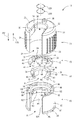
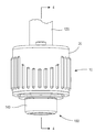
도 1은 연결부 검증기의 사시도이다.
도 2는 도 1에 도시된 연결부 검증기의 분해 사시도이다.
도 3은 유체 연결부와 결합된 도 1에 도시된 연결부 검증기의 사시도이다.
도 4는 일반적으로 도 3의 선 4-4를 따라서 취한 연결부 검증기 및 유체 연결부의 횡단면도이다.
도 5는, 연결부 검증기가 분리된, 도 4에 도시된 연결부 검증기 및 유체 연결부의 횡단면도이다.
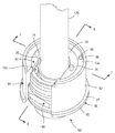
도 6은, 칼라 및 회로 기판이 제거된, 유체 연결부와 결합된 도 1에 도시된 연결부 검증기의 사시도이다.
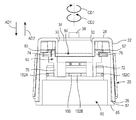
도 7은, 칼라 및 회로 기판이 조립된, 일반적으로 도 6의 선 7-7를 따라서 취한 연결부 검증기의 횡단면도이다.
도 8은, 칼라 및 회로 기판이 조립된, 일반적으로 도 6의 선 8-8을 따라서 취한 연결부 검증기의 횡단면도이다.
도 9는 스냅 링과 결합된 연결부 검증기의 저면도이다.Several embodiments are described by way of example only with reference to the accompanying schematic drawings in which corresponding reference signs indicate corresponding parts.
1 is a perspective view of a connection verifier.
FIG. 2 is an exploded perspective view of the connection verifier shown in FIG. 1.
3 is a perspective view of the connection verifier shown in FIG. 1 combined with a fluid connection.
4 is a cross-sectional view of the connection verifier and fluid connection generally taken along line 4-4 of FIG. 3.
FIG. 5 is a cross-sectional view of the connection verifier and fluid connection shown in FIG. 4 with the connection verifier removed.
6 is a perspective view of the connection verifier shown in FIG. 1 combined with a fluid connection, with the collar and circuit board removed.
FIG. 7 is a cross-sectional view of the connector verifier taken along line 7-7 of FIG. 6, with the collar and circuit board assembled.
8 is a cross-sectional view of a connector verifier taken along lines 8-8 of FIG. 6, with the collar and circuit board assembled.
9 is a bottom view of the connection verifier coupled with the snap ring.
먼저, 상이한 도면들 상의 유사한 도면 번호들이 동일한, 또는 기능적으로 유사한 구조적 요소들을 식별한다는 것을 이해하여야 할 것이다. 청구항은 개시된 양태로 제한되지 않는다는 것을 이해하여야 한다.First, it will be understood that similar drawing numbers on different drawings identify identical or functionally similar structural elements. It should be understood that the claims are not limited to the disclosed aspects.
또한, 본 개시 내용이 설명된 바와 같은 특정 방법론, 재료, 및 수정으로 제한되지 않고, 당연히 변경될 수 있다는 것을 이해하여야 한다. 또한, 본원에서 사용된 용어는 단지 특정 양태를 설명하기 위한 것이고, 첨부된 청구항의 범위를 제한하기 위한 것이 아님을 또한 이해할 수 있을 것이다.In addition, it should be understood that the present disclosure is not limited to specific methodologies, materials, and modifications as described, and may of course be changed. In addition, it will also be understood that the terminology used herein is for the purpose of describing certain aspects only and is not intended to limit the scope of the appended claims.
달리 규정되는 바가 없는 한, 본원에서 사용된 모든 기술적 및 과학적 용어가 본 개시 내용이 속하는 업계의 당업자에 의해서 일반적으로 이해되는 바와 같은 의미를 갖는다. 본원에서 설명된 것과 유사하거나 동일한 임의의 방법, 장치 또는 재료가 예시적인 실시예의 실행 또는 테스트에서 이용될 수 있다는 것을 이해하여야 한다. 본 개시 내용의 조립체는 유압장치, 전자장치, 및/또는 공압장치에 의해서 구동될 수 있다.Unless otherwise specified, all technical and scientific terms used herein have the meaning as commonly understood by one of ordinary skill in the art to which this disclosure belongs. It should be understood that any method, device or material similar or identical to that described herein can be used in the practice or testing of an exemplary embodiment. The assembly of the present disclosure can be driven by hydraulics, electronics, and/or pneumatics.
"실질적으로"라는 용어는 "거의", "아주 거의", "약", "대략적으로", "근처의", "경계 상의", "근접하여", "본질적으로", "~의 이웃의", "~에 근접하여" 등과 같은 용어와 동의어이고, 그러한 용어는 명세서 및 청구항에서 표시된 바와 같이 상호 교환 가능하게 사용될 수 있다는 것을 이해하여야 한다. "근접한"이라는 용어는 "근처의", "근접한", "인접한", "이웃하는", "가까운", "붙어 있는" 등과 같은 용어와 동의어이고, 그러한 용어는 명세서 및 청구항에서 표시된 바와 같이 상호 교환 가능하게 사용될 수 있다는 것을 이해하여야 한다. "대략적으로"라는 용어는 특정 값의 10% 이내의 값을 의미하기 위한 것이다.The terms "substantially" are "almost", "very nearly", "about", "approximately", "near", "boundary", "closely", "essentially", "of neighbors It should be understood that it is synonymous with terms such as ", "close to" and the like, and such terms may be used interchangeably as indicated in the specification and claims. The term “near” is synonymous with terms such as “near”, “near”, “adjacent”, “neighborhood”, “close”, “sticky”, etc., and such terms are interchangeable as indicated in the specification and claims It should be understood that it can be used interchangeably. The term "approximately" is intended to mean a value within 10% of a particular value.
"회전 가능하지 않게 연결된" 요소는: 요소들 중 하나가 회전될 때마다, 모든 구성요소가 회전되도록; 그리고 요소들 사이의 상대적인 회전은 가능하지 않도록, 요소들이 연결된 것을 의미한다. 회전 가능하지 않게 연결된 요소들의 서로에 대한 반경방향 및/또는 축방향 이동은 가능하나, 필수적인 것은 아니다.An "non-rotatably connected" element includes: every time one of the elements is rotated, all components are rotated; And it means that the elements are connected so that relative rotation between the elements is not possible. Radial and/or axial movement of non-rotatable connected elements relative to each other is possible, but is not necessary.
이제 도면을 참조하면, 도 1은 연결부 검증기(10)의 사시도이다. 도 2는 연결부 검증기(10)의 분해 사시도이다. 연결부 검증기(10)는 일반적으로 칼라(20), 회로 기판(40), 스위치(60), 및 삽입체(80)를 포함한다.Referring now to the drawings, FIG. 1 is a perspective view of a
칼라(20)는 일반적으로 원통형이고, 반경방향 외측 대면 표면(22), 반경방향 내측 대면 표면(24), 하단 표면(26), 및 상단 표면(28)을 포함한다. 칼라(20)는, 반경방향 내측 대면 표면(24)에 대해서 실질적으로 동심적으로 배열되는 반경방향 내측 대면 표면(34), 및 반경방향 내측 대면 표면(34)의 곡률에 대해서 실질적으로 접선적으로(tangent to) 배열되는 표면(30 및 32)을 더 포함한다. 표면(30 및 32)이 반경방향 내측 대면 표면(34)을 개방하여, 개구부(21)를 형성한다. 예시적인 실시예에서, 반경방향 외측 대면 표면(22)은 부가된 파지를 위한 복수의 리브를 포함한다. 예시적인 실시예에서, 반경방향 외측 대면 표면은 부가된 파지를 위한 다른 형태의 돌출부 또는 마찰 재료를 포함한다. 상단 표면(28)은 도관(38)을 포함한다. 도관(38)은 회로 기판(40)(및 표시부 조명등(55))을 와이어와 같은 전기 전도체를 통해서 전원에 연결하도록 배열된다. 예시적인 실시예에서, 표시부 조명등(55)을 통과하여 볼 수 있도록, 칼라(20)가 반투명하다. 예시적인 실시예에서, 표시부 조명등(55)을 통과하여 볼 수 있도록, 칼라(20)가 투명하다. 예시적인 실시예에서, 칼라(20)는 불투명하고, 표시부 조명등(55)을 통과하여 볼 수 있도록, 표시부 조명등(55)에 근접한 창을 더 포함한다. 예시적인 실시예에서, 반경방향 내측 대면 표면(34)은 절취부(36)를 더 포함한다.The
회로 기판(40)은 일반적으로 디스크-형상이고, 반경방향 외측 대면 표면(42), 반경방향 내측 대면 표면(44), 하단 표면(46), 및 상단 표면(48)을 포함한다. 예시적인 실시예에서, 회로 기판(40)은 인쇄 회로 기판(PCB)이다. 회로 기판(40)은, 반경방향 내측 대면 표면(44)의 곡률에 실질적으로 접선적으로 배열되는 표면(43 및 45)을 더 포함한다. 표면(43 및 45)이 반경방향 내측 대면 표면(44)을 개방하여, 개구부(41)를 형성한다. 상단 표면(48)은 회로망의 적어도 일부, 단자(51), 단자(52), 및 표시부 조명등(55)과 같은 표시부 장치를 포함한다. 이하에서 더 구체적으로 설명되는 바와 같이, 표시부 조명등(55)을 활성화하기 위해서 그리고 확실한 연결을 확인하기 위해서, 단자(51 및 52)가 핀(74 및 76)과 각각 접촉되도록 배열된다. 예시적인 실시예에서, 핀들과 단자들 사이의 물리적 접촉이 발생될 필요가 없도록, 단자(51 및 52)는 핀(74 및 76)의 근접한 위치를 각각 감지하도록 배열된 센서들이다. 도시된 실시예에서, 회로 기판(40)이 2개의 단자를 포함하나; 임의의 적합한 수의 단자가 이용될 수 있다는 것을 이해하여야 한다. 예시적인 실시예에서, 표시부 조명등(55)은 상단 표면(48) 상에 배열되지 않고, 칼라(20) 상에 또는 회로 기판(40) 외부의 다른 위치에 배열된다. 표시부 조명등(55)은, 백열 램프, 소형 형광 램프, 할로겐 램프, 금속 할로겐 램프, 발광 다이오드, 형광등, 네온 램프, 고강도 방전 램프 및 저압 나트륨 램프와 같은, 종래 기술에서 알려진 임의의 적합한 조명등일 수 있다. 회로 기판(40)은, 단자(51 및 52)에 근접하여 각각 배열되고 반경방향 내측 대면 표면(44)으로부터 반경방향 외측으로 연장되는 슬롯(49 및 50)을 더 포함한다. 이하에서 더 구체적으로 설명되는 바와 같이, 슬롯(49)은 핀(74)을 위한 외주 경계를 제공하고, 슬롯(50)은 핀(76)을 위한 외주 경계를 제공한다. 예시적인 실시예에서, 스위치(60)가 회로 기판(40)에 대해서 원주 방향(CD1)으로 회전될 때 핀(74)이 단자(51)와 접촉되도록, 단자(51)는 슬롯(49)에 인접하여 또는 그와 중첩되어 배열된다. 예시적인 실시예에서, 스위치(60)가 회로 기판(40)에 대해서 원주 방향(CD2)으로 회전될 때 핀(76)이 단자(52)와 접촉되도록, 단자(52)는 슬롯(50)에 인접하여 또는 그와 중첩되어 배열된다. 회로 기판(40)은 반경방향 외측 대면 표면(42)에 근접하여 배열된 홀(54 및 56)을 더 포함한다. 예시적인 실시예에서, 홀(54 및 56)은 반경방향 외측 대면 표면(42)으로부터 반경방향 내측으로 연장된다. 이하에서 더 구체적으로 설명되는 바와 같이, 회로 기판(40)을 삽입체(80)에 회전 가능하지 않게 연결하기 위해서, 홀(54 및 56)이 맞춤못(dowel)(94 및 96)과 각각 결합되도록 배열된다. 도시된 실시예에서, 연결부 검증기(10)가 회로 기판(40)을 삽입체(80)와 연결하기 위해서 2개의 홀 및 2개의 맞춤못을 포함하지만; 회로 기판(40)을 삽입체(80)에 회전 가능하지 않게 연결하기에 적합한 임의의 수의 홀 및 맞춤못이 이용될 수 있다는 것을 이해하여야 한다.The
회로 기판(40)은, 핀(74 및 76) 중 하나가 그 상응 단자에 접촉될 때 표시부 조명등(55)과 같은 표시부 장치가 활성화되게 하고, 그에 의해서 확실한 연결을 나타내게 하는 임의의 적합한 회로 기판(또는 회로 기판들)을 포함한다. 예시적인 실시예에서, 회로 기판(40)은, 표시부 조명등(55)과 같은 표시부 장치가, 이하의 순서 모두로, 핀(74 및 76) 중 하나가 그 상응 단자에 접촉될 때, 그리고 후속하여 핀(74 및 76) 중 다른 하나가 그 상응 단자에 접촉될 때 활성화되게 하고, 그에 의해서 확실한 연결을 나타내게 하는 임의의 적합한 회로 기판이다. 예시적인 실시예에서, 회로 기판(40)은 진동 장치(예를 들어, 진동 모터)를 포함하고, 그에 따라 핀(74 및 76) 중 하나가 그 상응 단자와 접촉될 때, 진동 장치가 연결부 검증기(10)를 진동시켜 확실한 연결을 표시한다. 예시적인 실시예에서, 회로 기판(40)은 진동 장치(예를 들어, 진동 모터)를 포함하고, 그에 따라 이하의 순서 모두로, 핀(74 및 76) 중 하나가 그 상응 단자와 접촉될 때, 그리고 후속하여 핀(74 및 76) 중 다른 하나가 그 상응 단자에 접촉될 때, 진동 장치가 연결부 검증기(10)를 진동시켜 확실한 연결을 표시한다. 예를 들어, 진동 장치는, 진동하는 편심 캠을 갖는 모터 또는 인가된 파형에 응답하여 진동하는 압전 장치의 형태를 취할 수 있는 촉각적 장치일 수 있다. 압전 장치는 또한 청각적 출력을 생성할 수 있다. 예시적인 실시예에서, 회로 기판(40)은 음향 장치(예를 들어, 스피커 및 임의의 다른 필요 음향 장비, 예를 들어 증폭기)를 포함하고, 그에 따라 핀(74 및 76) 중 하나가 그 상응 단자와 접촉될 때, 스피커가 소음을 출력하여 확실한 연결을 표시한다. 예시적인 실시예에서, 회로 기판(40)은 음향 장치(예를 들어, 스피커 및 임의의 다른 필요 음향 장비, 예를 들어 증폭기)를 포함하고, 그에 따라 이하의 순서 모두로, 핀(74 및 76) 중 하나가 그 상응 단자와 접촉되고, 후속하여 핀(74 및 76) 중 다른 하나가 그 상응 단자에 접촉될 때, 스피커가 소음을 출력하여 확실한 연결을 표시한다. 회로 기판(40)은 메모리 및 프로그래밍 가능 입/출력 주변장치와 함께 하나 이상의 중앙 프로세싱 유닛(CPU)을 포함하는 마이크로제어기를 더 포함할 수 있다. 이하에서 더 구체적으로 설명되는 바와 같이, 마이크로제어기는: 확실한 연결의 검증 시에 표시부 조명등(55)(또는 다른 표시부 장치)을 활성화시키기 위해서, 전송 장치를 이용하여 원격 위치에 있는 수신기에 신호 전송을 개시하여 확실한 연결(또는 확실하지 않은 연결)을 표시하기 위해서, 그리고 도구 실패 표시부를 활성화시키기 위해서 이용될 수 있다.The
스위치(60)는 반경방향 외측 대면 표면(62), 반경방향 내측 대면 표면(64), 하단 표면(66), 및 상단 표면(68)을 포함한다. 스위치(60)는, 반경방향 내측 대면 표면(64)의 곡률에 실질적으로 접선적으로 배열되는 표면(63 및 65)을 더 포함한다. 표면(63 및 65)이 반경방향 내측 대면 표면(64)을 개방하여, 개구부(61)를 형성한다. 핑거(70 및 72)가 축방향(AD1)으로 하단 표면(66)으로부터 연장된다. 핑거(70 및 72)는 삽입체(80)의 슬롯(90 및 92)과 각각 결합되고, 내부에서 원주 방향으로 변위될 수 있다. 예시적인 실시예에서, 이하에서 더 구체적으로 설명되는 바와 같이, 핑거(70 및 72)는 스냅 링(150)과 결합되도록 배열된 곡선형 돌출부이다. 그러나, 핑거(70 및 72)가, 스냅 링(150)과의 결합에 적합한 정사각형-형상의 각기둥, 직사각형-형상의 각기둥, 삼각형-형상의 각기둥 등과 같은, 임의의 다른 기하형태를 가질 수 있다는 것을 이해하여야 한다. 핀(74 및 76)은, 축방향(AD1)에 반대되는, 축방향(AD2)으로 상단 표면(68)으로부터 연장된다. 핀(74 및 76)은 회로 기판(40)의 슬롯(49 및 50)과 각각 결합되고, 내부에서 원주 방향으로 변위될 수 있다. 예시적인 실시예에서, 이하에서 더 구체적으로 설명되는 바와 같이, 핀(74 및 76)은 단자(51 및 52)와 각각 결합되도록 배열된 원통형 돌출부들이다. 그러나, 핀(74 및 76)이, 단자(51 및 52)와의 결합에 적합한 정사각형-형상의 각기둥, 직사각형-형상의 각기둥, 삼각형-형상의 각기둥 등과 같은, 임의의 다른 기하형태를 가질 수 있다는 것을 이해하여야 한다. 조립될 때, 스위치(60)는 삽입체(80), 회로 기판(40), 및 칼라(20)에 대해서 적어도 부분적으로 회전될 수 있다.The
삽입체(80)는 일반적으로 원통형이고, 반경방향 외측 대면 표면(82), 반경방향 내측 대면 표면(84), 플랜지(86), 및 상단 표면(88)을 포함한다. 삽입체(80) 및 칼라(20)는 회전 가능하지 않게 연결된다. 플랜지(86)는 하단 표면(85) 및 상단 표면(87)을 포함한다. 삽입체(80)는 홈(98)을 형성하는 반경방향 내측 대면 표면(106), 및 반경방향 내측 대면 표면(106)으로부터 반경방향 외측으로 연장되는 슬롯(90 및 92)을 더 포함한다. 삽입체(80)는, 반경방향 내측 대면 표면(106)의 곡률에 실질적으로 접선적으로 배열되는 표면(107 및 108)을 더 포함한다. 표면(107 및 108)이 반경방향 내측 대면 표면(106)을 개방하여, 개구부(81)를 형성한다. 홈(98)은 표면(100)을 포함한다. 연결부 검증기(10)가 조립될 때, 스위치(60)는 홈(98) 내에 배열되고, 하단 표면(66)은 표면(100)에 근접하여 또는 그에 접경되어 배열되고, 핑거(70 및 72)는 슬롯(90 및 92)의 각각을 통해서 축방향(AD1)으로 연장된다. 스위치(60)가 삽입체(80)에 대해서 원주 방향(CD1 및 CD2)으로 변위될 수 있도록, 핑거(70 및 72)와 각각의 슬롯(90 및 92) 사이에 원주 방향 간극이 존재한다. 삽입체(80)는, 표면(104)을 가지는 홈(102)을 더 포함한다. 예시적인 실시예에서, 홈(98 및 102)은 동심적으로 배열된다. 삽입체(80)는, 축방향(AD2)으로 표면(104)으로부터 연장되는 맞춤못(94 및 96)을 더 포함한다. 회로 기판(40)을 삽입체(80)에 회전 가능하지 않게 연결하기 위해서, 맞춤못(94 및 96)이 홀(54 및 56)과 결합되도록 배열된다. 연결부 검증기(10)가 조립될 때, 회로 기판 스위치(60)가 홈(102) 내에 배열되고, 하단 표면(46)은 표면(104)에 근접하여 또는 그에 접경되어 배열되고, 홀(54 및 56)은 맞춤못(94 및 96)과 각각 결합되며, 핀(74 및 76)은 슬롯(49 및 50)의 각각을 통해서 축방향(AD2)으로 연장된다. 스위치(60)가 회로 기판(40)에 대해서 원주 방향(CD1 및 CD2)으로 변위될 수 있도록, 핀(74 및 76)과 각각의 슬롯(49 및 50) 사이에 원주 방향 간극이 존재한다. 예시적인 실시예에서, 연결부 검증기(10)가 조립될 때, 상단 표면(48)은 상단 표면(88)과 실질적으로 같은 높이이거나 그와 공통 평면적이다.The
스위치(60)가 홈(98) 내에 배열되고 회로 기판(40)이 홈(102) 내에 배열된 후에, 칼라(20)가 삽입체(80) 위에 피팅된다. 연결부 검증기(10)가 조립될 때, 반경방향 내측 대면 표면(24)은 반경방향 외측 대면 표면(82)에 근접하여 또는 그에 접경되어 배열되고, 하단 표면(26)은 상단 표면(87)에 근접하여 또는 그에 접경되어 배열된다. 또한, 개구부(21, 41, 61, 및 81)가 전반적으로 정렬되어 개구부(11)를 형성한다. 칼라(20), 회로 기판(40), 및 삽입체(80)는 회전 가능하지 않게 연결된다. 스위치(60)는 칼라(20), 회로 기판(40), 및 삽입체(80)에 대해서 적어도 부분적으로 회전될 수 있다. 접착제, 볼트, 나사, 못, 리벳, 맞춤못과 같은 임의의 적합한 수단을 이용하여, 또는 압력/억지 피팅(force/interference fit)에 의해서, 칼라(20), 회로 기판(40), 및 삽입체(80)가 함께 고정될 수 있다는 것을 이해하여야 한다.After the
연결부 검증기(10)는, 회로 기판(40)에 그리고 선택적으로 메모리 장치 또는 마이크로제어기에 전기적으로 연결되는 전송 장치를 더 포함한다. 전송 장치는, 유체 연결부가 확실하다는 것 또는 확실치 않다는 것을 나타내는 신호를 원격 위치에 전송하도록 배열된다. 예시적인 실시예에서, 전송 장치는, 와이어 또는 광섬유 케이블과 같은 전기 케이블(즉, 물리적 연결 형태)을 통해서 신호를 송신하도록 배열된다. 전송 장치는 I2C(inter-integrated circuit), CAN(controller area network), LIN(local interconnect network), 또는 당업계에 알려진 임의의 적합한 통신 프로토콜을 이용할 수 있다. 예시적인 실시예에서, 전송 장치는, 송신된 데이터(즉, 유체 연결부가 확실하게 연결되었는지 또는 그렇지 않은 지의 여부)를 기록하는 원격 위치의 수신기에 무선 통신을 송신하도록 배열된다. 전송 장치는 당업계에 알려진 임의의 적합한 방법, 예를 들어 Bluetooth® 통신, 무선 주파수, 적외선, 및 Wi-Fi® 통신을 이용하여 데이터를 전송할 수 있다. 예시적인 실시예에서, 전송 장치는 유체 연결부 식별 번호, 연결부 검증기 식별 번호, 연결부 검증기의 남은 수명, 차량 식별 번호(VIN), 부품 번호(예를 들어, 엔진, 라디에이터 등) 및 해당 부품에 대한 일련 번호, 유체 연결부가 확실하다는 검증, 및/또는 유체 연결부가 확실하지 않다는 검증을 전송할 수 있다. 예시적인 실시예에서, 연결부 검증기가 컴퓨터와 같은 다른 장치와 함께 운용되어, 각각의 검사의 각각의 검사의 전자적 기록을 보관 할 수 있고 통과/실패 레이블을 인쇄할 수 있다. 예시적인 실시예에서, 통과/실패 레이블은 유체 연결부에 연결되거나 그와 함께 유지된다.The
연결부 검증기(10)는, 연결부 검증기(10)가 교체되어야 한다는 것을 나타내기 위해서, 조명등, 진동 장치, 또는 음향 장치와 같은 도구 실패 표시부를 더 포함할 수 있다. 이러한 실시예에서, 연결부 검증기(10)는, 예를 들어, 연결부 검증기(10)가 미리 규정된 수와 동일한 횟수로 이용되었을 때 도구 실패 표시부를 활성화하도록(즉, 조명등이 턴 온 되도록, 진동 장치가 진동하도록, 음향 장치가 음향을 생성하도록), 미리 규정된 수로 프로그래밍된 메모리 장치 또는 마이크로제어기를 포함할 수 있다. 마이크로제어기는 또한 연결부 검증기(10)가 사용된 횟수를 계산할 수 있고, 안전 인자를 갖는 현재의 잔류 수명 계산을 이용하여, 연결부 검증기(10)의 잔류 수명을 연속적으로 결정할 수 있다.The
도 3은 유체 연결부(160)와 결합된 연결부 검증기(10)의 사시도이다. 도 4는 일반적으로 도 3의 선 4-4를 따라서 취한 연결부 검증기(10) 및 유체 연결부(160)의 횡단면도이다. 도 5는, 연결부 검증기(10)가 분리된, 도 4에 도시된 연결부 검증기(10) 및 유체 연결부(160)의 횡단면도이다. 이하의 설명은 도 3 내지 도 5를 고려하여 읽혀야 한다. 연결부 검증기(10)는 일반적으로 관 단부 형태부(120), 유체 연결체(140), 및 스냅 링(150)을 포함한다.3 is a perspective view of a
관 단부 형태부(120)는 단부(122), 섹션(123), 쇼울더(127), 섹션(129), 단부(132), 및 관통-보어(121)를 포함한다. 관통-보어(121)는 단부(122)로부터 단부(132)까지 관 단부 형태부(120)를 통해서 연장된다. 섹션(123)은 단부(122)와 쇼울더(127) 사이에 배열되고, 반경방향 외측 대면 표면(124)을 포함한다. 반경방향 외측 대면 표면(124)은 실질적으로 일정한 직경을 포함한다. 쇼울더(127)는 섹션(123)과 섹션(129) 사이에 배열되고, 반경방향 외측 대면 표면(126)을 포함한다. 반경방향 외측 대면 표면(126)은 선형 원뿔 형상이고, 축방향(AD2)으로 직경이 증가된다. 섹션(129)은 쇼울더(127)와 단부(132) 사이에 배열되고, 반경방향 외측 대면 표면(130)을 포함한다. 반경방향 외측 대면 표면(130)은 실질적으로 일정한 직경을 포함한다. 쇼울더(127)는 쇼울더 표면(128)을 통해서 반경방향 외측 대면 표면(130)에 연결된다. 관 단부 형태부(120)는, 구체적으로 단부(122)가 먼저, 유체 연결체(140) 내로 삽입되도록 배열된다. 관 단부 형태부(120)는 직선형 램프(즉, 일정한 선형적 램프) 또는 곡선형 램프를 이용할 수 있고, 스냅 링(150)이 쇼울더(127) 위에 스냅 결합될 때까지 유체 연결체(140) 내로 삽입된다. 관 단부 형태부(120)는, 스냅 링 또는 와이어 클립을 유체 연결체 내에서 변위시켜 관 단부 형태부를 유체 연결체 내에 고정하기 위해서, 관 단부 형태부의 외부 표면 상에서 반경방향 외측으로 그리고 축방향으로 연장되는, 램프를 포함하는 임의의 통상적인 관 단부 형태부일 수 있다는 것을 이해하여야 한다. 이하에서 더 구체적으로 설명되는 바와 같이, 유체 연결부(160)가 확실하게 연결되었다는 것을 결정하기 위해서, 연결부 검증기(10)는 본질적으로 스냅 링(150)이 쇼울더(127) 위에 "스냅 결합되었는" 지를 검증한다.The
유체 연결체(140)는 관통-보어(142), 반경방향 내측 대면 표면(144), 반경방향 내측 대면 표면(146), 및 반경방향 외측 대면 표면(148)을 포함한다. 반경방향 외측 대면 표면(148)은 홈(149)을 포함한다. 스냅 링(150)은 홈(149) 내에 배열된다. 스냅 링(150)은 돌출부(152A, 152B, 및 152C)(도 9 참조)를 포함한다. 돌출부(152A 내지 152C)는 홈(149) 내의 홀을 통해서 반경방향 내측으로 연장되어, 쇼울더(127), 구체적으로 쇼울더 표면(128)과 결합된다.The
유체 연결부(160)가 확실하게 연결된 것을 검증하기 위해서, 도 5에(즉, 분리되어) 도시된 바와 같이, 연결부 검증기(10)는 먼저 개구부(11)(도 1에 도시된 개구부(11))를 통해서 관 단부 형태부(120) 주위에 배열된다. 이어서, 연결부 검증기(10)는, 도 4에 도시된 결합 위치에 있을 때까지, 축방향(AD1)으로 관 단부 형태부(120) 아래로 활주된다. 도 4에서, 연결부 검증기(10)는, 핑거(70 및 72)가 스냅 링(150) 또는 쇼울더 표면(128)(미도시)과 접촉될 때까지 축방향(AD1)으로 관 단부 형태부(120) 아래로 활주되었다.In order to verify that the
도 6은 유체 연결부(160)와 결합된 연결부 검증기(10)의 사시도이다. 관찰을 위해서, 칼라(20) 및 회로 기판(40)을 제거하였다. 확인될 수 있는 바와 같이, 핑거(70)는 슬롯(90)을 경유하여 삽입체(80)를 통해서 아래쪽으로 연장되고, 스냅 링(150)의 돌출부와 결합/접촉되도록 배열된다.6 is a perspective view of a
도 7은 일반적으로 도 6의 선 7-7를 따라서 취한 연결부 검증기(10)의 횡단면도이다. 관찰을 위해서, 관 단부 형태부(120) 및 유체 연결체(140)를 제거하였다. 핑거(70 및 72)는 스냅 링(150)의 돌출부들 사이에서 방향(AD1)으로 연장된다. 일단 완전히 결합되면, 연결부 검증기(10)는 원주 방향(CD1 및 CD2) 중 하나를 따라 회전되고, 그에 따라 핑거(70 및 72) 중 하나가 돌출부와 접촉되고, 이는 스위치(60)가 원주 방향으로 변위되게 하고 핀(74 및 76) 중 하나가 각각의 단자에 접촉되게 한다. 예를 들어, 연결부 검증기(10)가 원주 방향(CD1)으로 회전될 때, 핑거(70 및/또는 72)는 돌출부(152B 및/또는 152C)와 각각 접촉되어, 스위치(60)를 회로 기판(40)에 대해서 원주 방향(CD2)으로 변위시키고 핀(76)이 단자(52)와 결합되도록 강제한다. 예를 들어, 연결부 검증기(10)가 원주 방향(CD2)으로 회전될 때, 핑거(70 및/또는 72)는 돌출부(152A 및/또는 152B)와 각각 접촉되어, 스위치(60)를 회로 기판(40)에 대해서 원주 방향(CD1)으로 변위시키고 핀(74)이 단자(51)와 결합되도록 강제한다. 전술한 바와 같이, 예시적인 실시예에서, 스위치(60)가 하나의 핑거 만을 가질 수 있다는 것을 이해하여야 한다. 삽입체(80)(즉, 반경방향 내측 대면 표면(84))의 내경은, 핑거(70 및 72)가 스냅 클립(150)과 결합될 때 스냅 클립(150)이 확장될 수 있는 양을 제한한다는 것을 이해하여야 한다. 이러한 특징은 핑거(170 및 172)가 스냅 클립(150)을 홈(149)으로부터 이탈시키는 것을 방지한다.7 is a cross-sectional view of the
도 8은 일반적으로 도 6의 선 8-8를 따라서 취한 연결부 검증기(10)의 횡단면도이다. 관찰을 위해서, 관 단부 형태부(120) 및 유체 연결체(140)를 제거하였다. 도시된 바와 같이, 핑거(70)는 돌출부(152B)와 돌출부(152C) 사이에서 축방향(AD1)으로 아래로 연장된다.8 is a cross-sectional view of the
도 9는 스냅 링(150)과 결합된 연결부 검증기(10)의 저면도이다. 도 9에 도시된 바와 같이, 핑거(70)는 돌출부들(152A 및 152C) 사이에서 아래로 연장되고, 핑거(72)는 돌출부들(152A 및 152B) 사이에서 아래로 연장된다. 예시적인 실시예에서, 핑거(70 및 72)가 스냅 링(150)과 일단 결합되면(즉, 돌출부들을 통해서 연장되면), 연결부 검증기(10)는, 핑거(70)가 돌출부(152C)와 접촉될 때까지 방향(CD1)으로 회전되고, 그에 의해서 스위치(60)를 회로 기판(40)에 대해서 원주 방향(CD2)으로 변위시키고 핀(76)이 단자(52)와 결합되게 강제한다. 이는, 쇼울더(27) 위에 적절하게 조립된 제1 돌출부의 검증이다(제1 검증). 그 후에, 연결부 검증기(10)는, 핑거(72)가 돌출부(152B)와 접촉될 때까지 방향(CD2)으로 회전되고, 그에 의해서 스위치(60)를 회로 기판(40)에 대해서 원주 방향(CD1)으로 변위시키고 핀(74)이 단자(51)와 결합되도록 강제한다. 이는, 쇼울더(27) 위에 적절하게 조립된 제2 돌출부의 검증이다(제2 검증).9 is a bottom view of the
예시적인 실시예에서, 핑거(70 및 72)가 스냅 링(150)과 일단 결합되면(즉, 돌출부들을 통해서 연장되면), 연결부 검증기(10)는, 핑거(72)가 돌출부(152B)와 접촉될 때까지 방향(CD2)으로 회전되고, 그에 의해서 스위치(60)를 회로 기판(40)에 대해서 원주 방향(CD1)으로 변위시키고 핀(74)이 단자(51)와 결합되게 강제한다. 이는, 쇼울더(27) 위에 적절하게 조립된 제1 돌출부의 검증이다(제1 검증). 그 후에, 연결부 검증기(10)는, 핑거(70)가 돌출부(152C)와 접촉될 때까지 방향(CD1)으로 회전되고, 그에 의해서 스위치(60)를 회로 기판(40)에 대해서 원주 방향(CD2)으로 변위시키고 핀(76)이 단자(52)와 결합되도록 강제한다. 이는, 쇼울더(27) 위에 적절하게 조립된 제2 돌출부의 검증이다(제2 검증).In the exemplary embodiment, once the
예시적인 실시예에서, 표시부 조명등(55)은 제1 검증 시에 그리고 이어서 다시 제2 검증시에 활성화될 수 있다(각각의 단자가 접촉되면, 조명등이 턴 온된다). 예시적인 실시예에서, 그리고 전술한 바와 같이, 연결부 검증기(10)는, 양 단자들 모두가 설정된 기간 이내에 접촉되는 경우에만 표시부 조명등(55)을 활성화시키도록 프로그래밍될 수 있는 (예를 들어, 회로 기판(40)에 위치된) 마이크로제어기 또는 다른 컴퓨터 장치를 포함할 수 있다. 예를 들어, 마이크로제어기는 프로그램을 포함할 수 있고, 그러한 프로그램은 1) 단자(51) 및 단자(52) 중 하나가 각각의 핀에 의해서 접촉되는 것, 그리고 2) 단자(51) 및 단자(52) 중 다른 하나가 2초 이내에 각각의 핀에 의해서 접촉되는 것; 및/또는 3) 프로그램이 리셋되는 것을 요구한다. 이러한 프로그램에 따라, 단자(51 및 52)가 2초 이내에 서로 접촉되는 경우에, 표시부 조명등(55)이 활성화되고, 전송 장치는 유체 연결체가 확실하게 연결되었다는 것을 나타내는 신호를 원격 위치에 송신하고, 프로그램은 다른 유체 연결체에서의 이용을 위해서 리셋된다. 단자(51 및 52)가 2초 이내에 서로 접촉되지 않는 경우에, 표시부 조명등(55)은 활성화되지 않고, 전송 장치는 신호를 원격 위치에 송신하지 않고, 프로그램은 리셋된다. 당업계에 알려진 바와 같이, 유체 연결부가 확실하게 연결되었다는 것을 시각적으로 그리고 원격 위치(예를 들어, 데이터베이스 또는 목록)에서 모두 표시하도록 연결부 검증기(10)를 적절히 프로그래밍하기 위해서 여러 가지 프로그램이 이용될 수 있다.In an exemplary embodiment, the indicator light 55 can be activated at the first verification and then again at the second verification (when each terminal is touched, the lighting is turned on). In the exemplary embodiment, and as described above, the
전술한 개시 내용의 다양한 양태 그리고 다른 특징 및 기능, 또는 그 대안들이 많은 다른 상이한 시스템 또는 적용예로 희망에 따라 조합될 수 있다는 것이 이해될 것이다. 현재 예측되지 않고 예상되지 않는 다양한 대안, 수정, 변경 또는 개선이 당업자에 의해서 추후에 이루어질 수 있을 것이고, 그 각각은 또한 이하의 청구항에 포함될 것이다.It will be understood that various aspects and other features and functions of the foregoing disclosure, or alternatives thereof, can be combined as desired in many different different systems or applications. Various alternatives, modifications, changes or improvements that are currently unforeseen and unexpected will be made by those skilled in the art in the future, each of which will also be included in the following claims.
10
연결부 검증기
11
개구부
20
칼라
21
개구부
22
반경방향 외측 대면 표면
24
반경방향 내측 대면 표면
26
하단 표면
28
상단 표면
30
표면
32
표면
34
반경방향 내측 대면 표면
36
절취부
38
도관
40
회로 기판
41
개구부
42
반경방향 외측 대면 표면
43
표면
44
반경방향 내측 대면 표면
45
표면
46
하단 표면
48
상단 표면
49
슬롯
50
슬롯
51
단자
52
단자
55
표시부 조명등
54
홀
56
홀
60
스위치
61
개구부
62
반경방향 외측 대면 표면
63
표면
64
반경방향 내측 대면 표면
65
표면
66
하단 표면
68
상단 표면
70
핑거
72
핑거
74
핀
76
핀
80
삽입체
82
반경방향 외측 대면 표면
84
반경방향 내측 대면 표면
85
하단 표면
86
플랜지
87
상단 표면
88
상단 표면
90
슬롯
92
슬롯
94
맞춤못
96
맞춤못
98
홈
100
표면
102
홈
104
표면
106
반경방향 내측 대면 표면
107
표면
108
표면
120
관 단부 형태부
121
관통-보어
122
단부
123
섹션
124
반경방향 외측 대면 표면
126
반경방향 외측 대면 표면
127
쇼울더
128
쇼울더 표면
129
섹션
130
반경방향 외측 대면 표면
132
단부
140
유체 연결체
142
관통-보어
144
반경방향 내측 대면 표면
146
반경방향 내측 대면 표면
148
반경방향 외측 대면 표면
149
홈
150
스냅 링
152A
돌출부
152B
돌출부
152C
돌출부
160
유체 연결부10 Connection Verifier
11 opening
20 colors
21 opening
22 Radial outer facing surface
24 Radial inner facing surface
26 bottom surface
28 top surface
30 surfaces
32 surfaces
34 Radial inner facing surface
36 perforation
38 conduit
40 circuit board
41 opening
42 Radial outer facing surface
43 Surface
44 Radial inner facing surface
45 surface
46 Bottom surface
48 top surface
49 slots
50 slots
51 terminals
52 terminals
55 Indicator lights
54 holes
56 holes
60 switch
61 opening
62 Radial outer facing surface
63 surface
64 radially inner facing surface
65 surface
66 bottom surface
68 top surface
70 fingers
72 fingers
74 pin
76 pin
80 insert
82 Radial outer facing surface
84 Radial inner facing surface
85 bottom surface
86 flange
87 top surface
88 top surface
90 slots
92 slots
94 Custom nail
96 custom nails
98 home
100 surface
102 home
104 surface
106 Radial inner facing surface
107 surface
108 surface
120 tube end shape
121 through-bore
122 ends
123 sections
124 radially outer facing surface
126 Radial outer facing surface
127 Shoulder
128 shoulder surface
129 sections
130 radially outer facing surface
132 ends
140 fluid connector
142 through-bore
144 radial inner facing surface
146 radially inner facing surface
148 radial outer facing surface
149 home
150 snap ring
152A protrusion
152B protrusion
152C protrusion
160 fluid connections
Claims (20)
칼라;
칼라에 회전 가능하지 않게 연결되고 적어도 하나의 단자를 포함하는 회로 기판;
칼라에 회전 가능하게 연결되고, 적어도 하나의 단자와 접촉되도록 배열되며, 제1 축방향으로 연장되는 적어도 하나의 핑거를 포함하는 스위치; 및
스위치가 적어도 하나의 단자와 접촉할 때 활성화되도록 배열되는 표시 장치를 포함하는, 연결부 검증기.The connection verifier is:
color;
A circuit board not rotatably connected to the collar and including at least one terminal;
A switch rotatably connected to the collar, arranged to contact at least one terminal, and including at least one finger extending in a first axial direction; And
And a display device arranged to be activated when the switch contacts at least one terminal.
칼라는 실질적으로 동심적으로 내부에 배열된 삽입체를 포함하고, 삽입체는 제1 홈 및 제2 홈을 포함하는, 연결부 검증기.According to claim 1,
The collar comprises an insert arranged substantially concentrically therein, the insert comprising a first groove and a second groove, a connection verifier.
회로 기판이 제1 홈 내에 배열되고, 스위치는 제2 홈 내에 배열되는, 연결부 검증기.According to claim 2,
The circuit board verifier is arranged in the first groove, and the switch is arranged in the second groove.
스위치는 적어도 하나의 단자와 접촉되도록 배열된, 제1 축방향에 반대되는, 제2 축방향으로 연장되는 적어도 하나의 핀을 더 포함하는, 연결부 검증기.According to claim 1,
The switch further comprises at least one pin extending in the second axial direction, opposite the first axial direction, arranged to contact the at least one terminal.
회로 기판에 전기적으로 연결된 전송 장치를 더 포함하는, 연결부 검증기.According to claim 1,
A connection verifier further comprising a transmission device electrically connected to the circuit board.
전송 장치는, 유체 연결부의 연결 상태를 나타내는 신호를 원격 수신기에 전송하도록 동작 가능하게 배열되는, 연결부 검증기.The method of claim 5,
The transmission device is operatively arranged to transmit a signal indicative of the connection status of the fluid connection to the remote receiver.
회로 기판에 전기적으로 연결된 마이크로제어기를 더 포함하는, 연결부 검증기.According to claim 1,
And a microcontroller electrically connected to the circuit board.
표시 장치는 조명등인, 연결부 검증기.According to claim 1,
The display device is a lighting lamp, a connection verifier.
표시 장치는 진동 장치인, 연결부 검증기.According to claim 1,
The display device is a vibration device, a connection verifier.
표시 장치는 음향 장치인, 연결부 검증기.According to claim 1,
The display device is a sound device, a connection verifier.
칼라는 도관을 포함하고, 회로 기판은 도관을 통해서 전원에 연결되는, 연결부 검증기.According to claim 1,
The collar includes a conduit, and the circuit board is connected to a power source through the conduit, a connection verifier.
삽입체로서:
반경방향 외측 대면 표면;
반경방향 내측 대면 표면;
반경방향 내측 대면 표면 내에 배열된 제1 홈; 및
반경방향 내측 대면 표면 내에 배열된 제2 홈을 포함하는, 삽입체;
제1 홈 내에 배열되는 회로 기판으로서:
적어도 하나의 단자; 및
표시 장치를 포함하는, 회로 기판; 그리고
제2 홈 내에 배열되는 스위치로서:
제1 축방향으로 연장되고 적어도 하나의 단자와 접촉되도록 배열되는 적어도 하나의 핀; 및
제1 축방향에 반대되는 제2 축방향으로 연장되는 적어도 하나의 핑거를 포함하는, 스위치를 포함하는, 연결부 검증기.The connection verifier for fluid connections:
As insert:
A radially outer facing surface;
A radially inner facing surface;
A first groove arranged in a radially inner facing surface; And
An insert, including a second groove arranged in a radially inner facing surface;
As a circuit board arranged in the first groove:
At least one terminal; And
A circuit board including a display device; And
As a switch arranged in the second groove:
At least one pin extending in the first axial direction and arranged to contact at least one terminal; And
And a switch comprising at least one finger extending in a second axial direction opposite the first axial direction.
삽입체는, 반경방향 외측 대면 표면에 회전 가능하지 않게 연결된 칼라를 더 포함하는, 연결부 검증기.The method of claim 11,
The insert further comprises a collar non-rotatably connected to the radially outer facing surface.
회로 기판에 전기적으로 연결된 전송 장치를 더 포함하는, 연결부 검증기.The method of claim 11,
A connection verifier further comprising a transmission device electrically connected to the circuit board.
전송 장치는, 유체 연결부의 연결 상태를 나타내는 신호를 원격 수신기에 전송하도록 동작 가능하게 배열되는, 연결부 검증기.The method of claim 14,
The transmission device is operatively arranged to transmit a signal indicative of the connection status of the fluid connection to the remote receiver.
회로 기판에 전기적으로 연결된 마이크로제어기를 더 포함하는, 연결부 검증기.The method of claim 11,
And a microcontroller electrically connected to the circuit board.
표시 장치는 조명등인, 연결부 검증기.The method of claim 11,
The display device is a lighting lamp, a connection verifier.
표시 장치는 진동 장치인, 연결부 검증기.The method of claim 11,
The display device is a vibration device, a connection verifier.
회로 기판은 삽입체에 회전 가능하지 않게 연결되고; 그리고
스위치는 삽입체에 회전 가능하게 연결되는, 연결부 검증기.The method of claim 11,
The circuit board is non-rotatably connected to the insert; And
The switch is rotatably connected to the insert, a connection verifier.
삽입체로서:
반경방향 외측 대면 표면; 및
반경방향 내측 대면 표면을 포함하는, 삽입체;
반경방향 내측 대면 표면에 회전 가능하지 않게 연결되는 회로 기판으로서:
적어도 하나의 단자; 및
표시부 조명등을 포함하는, 회로 기판; 그리고
반경방향 내측 대면 표면에 회전 가능하게 연결되고, 적어도 하나의 단자와 접촉되도록 배열되며, 제1 축방향으로 연장되는 적어도 하나의 핑거를 포함하는, 스위치를 포함하는, 연결부 검증기.The connection verifier is:
As insert:
A radially outer facing surface; And
An insert, including a radially inner facing surface;
A circuit board that is non-rotatably connected to a radially inner facing surface:
At least one terminal; And
A circuit board including a display portion lighting; And
A connection verifier, comprising a switch, comprising at least one finger rotatably connected to the radially inner facing surface, arranged to contact at least one terminal, and extending in the first axial direction.
Applications Claiming Priority (3)
| Application Number | Priority Date | Filing Date | Title |
|---|---|---|---|
| US201762589968P | 2017-11-22 | 2017-11-22 | |
| US62/589,968 | 2017-11-22 | ||
| PCT/US2018/056885 WO2019103802A1 (en) | 2017-11-22 | 2018-10-22 | Connection verifier |
Publications (2)
| Publication Number | Publication Date |
|---|---|
| KR20200084352A true KR20200084352A (en) | 2020-07-10 |
| KR102402343B1 KR102402343B1 (en) | 2022-05-30 |
Family
ID=64110282
Family Applications (1)
| Application Number | Title | Priority Date | Filing Date |
|---|---|---|---|
| KR1020207017413A KR102402343B1 (en) | 2017-11-22 | 2018-10-22 | Connection Verifier |
Country Status (10)
| Country | Link |
|---|---|
| US (1) | US11608920B2 (en) |
| EP (1) | EP3714472B1 (en) |
| JP (1) | JP6997872B2 (en) |
| KR (1) | KR102402343B1 (en) |
| CN (1) | CN111373500B (en) |
| BR (1) | BR112020008719A2 (en) |
| CA (1) | CA3081661C (en) |
| MX (1) | MX2020004813A (en) |
| RU (1) | RU2744514C1 (en) |
| WO (1) | WO2019103802A1 (en) |
Families Citing this family (2)
| Publication number | Priority date | Publication date | Assignee | Title |
|---|---|---|---|---|
| FR3081203B1 (en) * | 2018-05-17 | 2020-05-15 | Hutchinson | FLUIDIC CONNECTION DEVICE FOR A MOTOR VEHICLE |
| DE102020108073A1 (en) * | 2020-03-24 | 2021-09-30 | Voss Automotive Gmbh | Connector with pre-assembly lock |
Citations (2)
| Publication number | Priority date | Publication date | Assignee | Title |
|---|---|---|---|---|
| US20040226807A1 (en) * | 2003-05-16 | 2004-11-18 | Ashton Robert H. | Rotary switch |
| JP2013089440A (en) * | 2011-10-18 | 2013-05-13 | Panasonic Corp | Rotary switch |
Family Cites Families (52)
| Publication number | Priority date | Publication date | Assignee | Title |
|---|---|---|---|---|
| FR2444331A1 (en) * | 1978-12-15 | 1980-07-11 | Ferodo Sa | Rotary switch with centre knob - is for switching electrical contacts and has annular knob for switching fluid lines of vehicle air conditioning system |
| GB8508757D0 (en) | 1985-04-03 | 1985-05-09 | Robson A R | Pipe couplings |
| US5152555A (en) * | 1991-03-26 | 1992-10-06 | Itt Corporation | Quick connect insertion indicator clip |
| US5441313A (en) | 1994-01-18 | 1995-08-15 | Bundy Corporation | Insertion indicator for quick connector |
| JP4511738B2 (en) | 1998-12-18 | 2010-07-28 | アコー テクノロジー インコーポレーテッド | Tube coupling |
| US6199913B1 (en) | 1999-09-29 | 2001-03-13 | Hsin-Fa Wang | Fast connector for gardening hose |
| ES2307607T3 (en) | 2000-04-19 | 2008-12-01 | Adrian Roger Poulton | CONNECTION DEVICE |
| RU15812U1 (en) * | 2000-07-17 | 2000-11-10 | Открытое акционерное общество "Чебоксарский приборостроительный завод "ЭЛАРА" | SWITCH SWIVEL |
| US6540285B2 (en) | 2000-10-13 | 2003-04-01 | Alfa Leisure, Inc. | Motorhome with increased interior ceiling height |
| RU24316U1 (en) * | 2002-02-26 | 2002-07-27 | Открытое акционерное общество "Автоэлектроарматура" | LIGHTING CONTROL MODULE |
| US6927651B2 (en) | 2003-05-12 | 2005-08-09 | Agilent Technologies, Inc. | Acoustic resonator devices having multiple resonant frequencies and methods of making the same |
| FR2863683B1 (en) | 2003-12-10 | 2006-02-17 | Legris Sa | INSTANT CONNECTION DEVICE |
| DE102004016599B3 (en) | 2004-04-03 | 2005-09-08 | Henn Gmbh & Co. Kg | Plug-in connection with rotation preventing stops for hoses and pipes has plug with guide grooves in end fitting into socket with inner and outer tubular housings |
| DE102004042085A1 (en) * | 2004-08-31 | 2006-03-02 | BSH Bosch und Siemens Hausgeräte GmbH | Rotary switch, in particular for a household appliance |
| DE102005017692B3 (en) | 2005-04-07 | 2006-05-11 | Festo Ag & Co. | Connecting device for fluid line has insertion formed as metallic stamped flexible part which contains cage element containing circular supporting section |
| AU2005331853B2 (en) | 2005-05-18 | 2011-09-01 | Neoperl Gmbh | Sanitary component, namely jet regulator or jet former for flowing, fluid media, method of producing such a sanitary component and use of a sanitary component |
| DE202005019978U1 (en) * | 2005-10-12 | 2006-04-20 | E.G.O. Elektro-Gerätebau GmbH | Operating device for an electrical appliance |
| JP2009543630A (en) | 2006-07-15 | 2009-12-10 | ノボ・ノルデイスク・エー/エス | Drug delivery system with rotatable coding element |
| EP1995752B1 (en) * | 2007-04-20 | 2013-10-16 | Harman Becker Automotive Systems GmbH | Multifunctional rotary switch |
| US10420880B2 (en) | 2007-10-02 | 2019-09-24 | West Pharma. Services IL, Ltd. | Key for securing components of a drug delivery system during assembly and/or transport and methods of using same |
| DE102007050033B3 (en) * | 2007-10-17 | 2008-11-13 | Continental Automotive Gmbh | Rotary actuator for use in operating unit of air conditioning system in motor vehicle, has coupling devices coupling rotary ring with light guide so that light emitting surface is arranged opposite to position indicator |
| GB0809685D0 (en) | 2008-05-28 | 2008-07-02 | Guest John Int Ltd | Improvements in or relating to tube couplings |
| US8181997B2 (en) | 2009-05-22 | 2012-05-22 | Hsin-Fa Wang | Water hose connector |
| DE102009043088B3 (en) * | 2009-09-25 | 2011-03-31 | A. Raymond Et Cie | Insertion control unit for checking the plug state of a male part in a receiving part and arrangement with such an insertion control unit and a receiving part |
| US9494268B2 (en) | 2009-10-21 | 2016-11-15 | Brasscraft Manufacturing Company | Supply stop with connection verification |
| US9506592B2 (en) | 2009-10-21 | 2016-11-29 | Brass-Craft Manufacturing Company | Supply stop with connection verification |
| JP5446801B2 (en) * | 2009-12-07 | 2014-03-19 | パナソニック株式会社 | Rotating electronic components |
| WO2011124631A1 (en) | 2010-04-09 | 2011-10-13 | Sanofi-Aventis Deutschland Gmbh | Coded drug reservoir connection element with bendable locking elements |
| GB201010501D0 (en) | 2010-06-22 | 2010-08-04 | Guest John Int Ltd | A tube coupling |
| US8328244B2 (en) | 2010-07-13 | 2012-12-11 | Robin Boley-Johnson, legal representative | Split GXR collar front mounted clamp assembly |
| US8366154B2 (en) | 2011-06-15 | 2013-02-05 | Wang Cheng-An | Water pipe connector |
| JP5950416B2 (en) | 2011-06-16 | 2016-07-13 | 株式会社東郷製作所 | Piping connector |
| JP2013120720A (en) * | 2011-12-08 | 2013-06-17 | Chugoku Electric Power Co Inc:The | Rotary knob with operation mode identification mechanism of change-over switch |
| AT512397B1 (en) | 2012-05-07 | 2013-08-15 | Henn Gmbh & Co Kg | Plug connection for connecting lines for pressurized liquids or gases |
| EP2728236B1 (en) | 2012-11-05 | 2017-04-19 | TI Automotive (Fuldabrück) GmbH | Quick connector coupling |
| TWI578359B (en) * | 2013-07-24 | 2017-04-11 | 達方電子股份有限公司 | Keyswitch, keyboard and related method of force feedback |
| GB201317990D0 (en) | 2013-10-11 | 2013-11-27 | Guest John Int Ltd | A conncetor |
| EP3097335B1 (en) | 2013-11-27 | 2020-01-08 | Oetiker NY, Inc. | A fluid coupling with lock connection |
| US8844974B1 (en) | 2013-12-31 | 2014-09-30 | Quick Fitting, Inc. | Cross platform grip ring release device and method |
| US9523464B2 (en) | 2014-03-05 | 2016-12-20 | Tri Technical Center Usa, Inc. | Cylindrical vibration-damping device equipped with outer bracket and outer bracket therefor |
| US9068680B1 (en) | 2014-05-30 | 2015-06-30 | Quick Fitting, Inc. | Push-to-connect fitting integrated packing arrangement, device and methods |
| US20170114935A1 (en) | 2014-05-30 | 2017-04-27 | Jiffy-Tite Co., Inc. | Fluid connector with full insertion assurance cap disconnect tool |
| ES2704073T3 (en) | 2014-05-30 | 2019-03-14 | Oetiker Ny Inc | Fluid connector with full insert safety cover with secondary interlock elements |
| JP6168559B2 (en) | 2014-08-07 | 2017-07-26 | 株式会社ニフコ | Locking mechanism of tubular body |
| CN104319146B (en) * | 2014-10-11 | 2017-02-01 | 成都瑞联电气股份有限公司 | Single breakpoint quick-action assistant switch |
| US9611970B2 (en) | 2014-11-06 | 2017-04-04 | Spears Manufacturing Co. | Pipe cap |
| US9791081B2 (en) | 2015-04-30 | 2017-10-17 | Opw-Engineered Systems, Inc. | Fluid system connection nozzle assembly |
| US20160379776A1 (en) * | 2015-06-27 | 2016-12-29 | Intel Corporation | Keyboard for an electronic device |
| US10823323B2 (en) | 2016-03-03 | 2020-11-03 | Oetiker Ny, Inc. | Fluid connector having a deformable tab and plug/connector assembly |
| CN105632828B (en) * | 2016-03-15 | 2018-01-09 | 宁波福尔达智能科技有限公司 | Automobile-used knob indicator assembling structure |
| GB2549510B (en) | 2016-04-20 | 2021-03-17 | John Guest International Ltd | A Connector |
| US9671049B1 (en) | 2016-07-27 | 2017-06-06 | Quick Fitting, Inc. | Hybrid push-to-connect fitting device and assembly |
-
2018
- 2018-10-22 CA CA3081661A patent/CA3081661C/en active Active
- 2018-10-22 MX MX2020004813A patent/MX2020004813A/en unknown
- 2018-10-22 JP JP2020526584A patent/JP6997872B2/en active Active
- 2018-10-22 WO PCT/US2018/056885 patent/WO2019103802A1/en unknown
- 2018-10-22 CN CN201880075516.9A patent/CN111373500B/en active Active
- 2018-10-22 RU RU2020119324A patent/RU2744514C1/en active
- 2018-10-22 EP EP18797490.2A patent/EP3714472B1/en active Active
- 2018-10-22 BR BR112020008719-0A patent/BR112020008719A2/en not_active Application Discontinuation
- 2018-10-22 US US16/766,332 patent/US11608920B2/en active Active
- 2018-10-22 KR KR1020207017413A patent/KR102402343B1/en active IP Right Grant
Patent Citations (2)
| Publication number | Priority date | Publication date | Assignee | Title |
|---|---|---|---|---|
| US20040226807A1 (en) * | 2003-05-16 | 2004-11-18 | Ashton Robert H. | Rotary switch |
| JP2013089440A (en) * | 2011-10-18 | 2013-05-13 | Panasonic Corp | Rotary switch |
Also Published As
| Publication number | Publication date |
|---|---|
| JP6997872B2 (en) | 2022-01-18 |
| JP2021504879A (en) | 2021-02-15 |
| US11608920B2 (en) | 2023-03-21 |
| CN111373500A (en) | 2020-07-03 |
| CA3081661C (en) | 2023-05-09 |
| RU2744514C1 (en) | 2021-03-11 |
| EP3714472A1 (en) | 2020-09-30 |
| CA3081661A1 (en) | 2019-05-31 |
| EP3714472B1 (en) | 2022-10-19 |
| KR102402343B1 (en) | 2022-05-30 |
| WO2019103802A1 (en) | 2019-05-31 |
| BR112020008719A2 (en) | 2020-11-03 |
| CN111373500B (en) | 2022-08-23 |
| MX2020004813A (en) | 2020-08-13 |
| US20200370695A1 (en) | 2020-11-26 |
Similar Documents
| Publication | Publication Date | Title |
|---|---|---|
| KR20200084352A (en) | Connection verifier | |
| US20120243253A1 (en) | Light ring for appliance control adjustable for console thickness | |
| CN108353457B (en) | Commissioning of wireless communication enabled devices | |
| CN108700280B (en) | Plastic downlight device with interlocking attachment features | |
| CN103004036B (en) | For the outer cover of electrically-actuated device | |
| WO2016169789A1 (en) | Lighting system | |
| EP3192334B1 (en) | A circuit board system | |
| KR102526341B1 (en) | joint verifier | |
| US10775004B2 (en) | Fully illuminated apparatus and method | |
| JP2016503225A5 (en) | ||
| WO2023274698A1 (en) | A housing for a lighting device, and a lighting device having the housing | |
| US11808392B2 (en) | Connection verifier | |
| EP3258648A1 (en) | Method and arrangement for downloading presets to nodes of a building automation system | |
| KR102595717B1 (en) | connection verifier | |
| US20230313977A1 (en) | Multi-function active accessories for led lamps | |
| CN210165342U (en) | Induction lamp with combination assembly | |
| EP3297258B1 (en) | Commissioning of a sensor in a home automation system | |
| JPH077015U (en) | Remote control switch adapter device | |
| CN109716022A (en) | The box lamp support of core slot is caught in and grounding assembly | |
| JP2014513880A (en) | System and method for electrical device control | |
| EP1889521A1 (en) | Device for receiving digital transmission protocol signals, particularly for lighting apparatuses |
Legal Events
| Date | Code | Title | Description |
|---|---|---|---|
| E902 | Notification of reason for refusal | ||
| E701 | Decision to grant or registration of patent right | ||
| GRNT | Written decision to grant |