KR20200083249A - Beam rotator unit and laser processing apparatus - Google Patents
Beam rotator unit and laser processing apparatus Download PDFInfo
- Publication number
- KR20200083249A KR20200083249A KR1020190171358A KR20190171358A KR20200083249A KR 20200083249 A KR20200083249 A KR 20200083249A KR 1020190171358 A KR1020190171358 A KR 1020190171358A KR 20190171358 A KR20190171358 A KR 20190171358A KR 20200083249 A KR20200083249 A KR 20200083249A
- Authority
- KR
- South Korea
- Prior art keywords
- laser light
- laser
- workpiece
- beam rotator
- irradiation position
- Prior art date
Links
Images


Classifications
-
- B—PERFORMING OPERATIONS; TRANSPORTING
- B23—MACHINE TOOLS; METAL-WORKING NOT OTHERWISE PROVIDED FOR
- B23K—SOLDERING OR UNSOLDERING; WELDING; CLADDING OR PLATING BY SOLDERING OR WELDING; CUTTING BY APPLYING HEAT LOCALLY, e.g. FLAME CUTTING; WORKING BY LASER BEAM
- B23K26/00—Working by laser beam, e.g. welding, cutting or boring
- B23K26/36—Removing material
- B23K26/38—Removing material by boring or cutting
- B23K26/382—Removing material by boring or cutting by boring
-
- B—PERFORMING OPERATIONS; TRANSPORTING
- B23—MACHINE TOOLS; METAL-WORKING NOT OTHERWISE PROVIDED FOR
- B23K—SOLDERING OR UNSOLDERING; WELDING; CLADDING OR PLATING BY SOLDERING OR WELDING; CUTTING BY APPLYING HEAT LOCALLY, e.g. FLAME CUTTING; WORKING BY LASER BEAM
- B23K26/00—Working by laser beam, e.g. welding, cutting or boring
- B23K26/02—Positioning or observing the workpiece, e.g. with respect to the point of impact; Aligning, aiming or focusing the laser beam
- B23K26/06—Shaping the laser beam, e.g. by masks or multi-focusing
- B23K26/064—Shaping the laser beam, e.g. by masks or multi-focusing by means of optical elements, e.g. lenses, mirrors or prisms
- B23K26/0648—Shaping the laser beam, e.g. by masks or multi-focusing by means of optical elements, e.g. lenses, mirrors or prisms comprising lenses
-
- B—PERFORMING OPERATIONS; TRANSPORTING
- B23—MACHINE TOOLS; METAL-WORKING NOT OTHERWISE PROVIDED FOR
- B23K—SOLDERING OR UNSOLDERING; WELDING; CLADDING OR PLATING BY SOLDERING OR WELDING; CUTTING BY APPLYING HEAT LOCALLY, e.g. FLAME CUTTING; WORKING BY LASER BEAM
- B23K26/00—Working by laser beam, e.g. welding, cutting or boring
- B23K26/02—Positioning or observing the workpiece, e.g. with respect to the point of impact; Aligning, aiming or focusing the laser beam
- B23K26/04—Automatically aligning, aiming or focusing the laser beam, e.g. using the back-scattered light
-
- B—PERFORMING OPERATIONS; TRANSPORTING
- B23—MACHINE TOOLS; METAL-WORKING NOT OTHERWISE PROVIDED FOR
- B23K—SOLDERING OR UNSOLDERING; WELDING; CLADDING OR PLATING BY SOLDERING OR WELDING; CUTTING BY APPLYING HEAT LOCALLY, e.g. FLAME CUTTING; WORKING BY LASER BEAM
- B23K26/00—Working by laser beam, e.g. welding, cutting or boring
- B23K26/02—Positioning or observing the workpiece, e.g. with respect to the point of impact; Aligning, aiming or focusing the laser beam
- B23K26/06—Shaping the laser beam, e.g. by masks or multi-focusing
- B23K26/064—Shaping the laser beam, e.g. by masks or multi-focusing by means of optical elements, e.g. lenses, mirrors or prisms
-
- B—PERFORMING OPERATIONS; TRANSPORTING
- B23—MACHINE TOOLS; METAL-WORKING NOT OTHERWISE PROVIDED FOR
- B23K—SOLDERING OR UNSOLDERING; WELDING; CLADDING OR PLATING BY SOLDERING OR WELDING; CUTTING BY APPLYING HEAT LOCALLY, e.g. FLAME CUTTING; WORKING BY LASER BEAM
- B23K26/00—Working by laser beam, e.g. welding, cutting or boring
- B23K26/08—Devices involving relative movement between laser beam and workpiece
- B23K26/082—Scanning systems, i.e. devices involving movement of the laser beam relative to the laser head
- B23K26/0821—Scanning systems, i.e. devices involving movement of the laser beam relative to the laser head using multifaceted mirrors, e.g. polygonal mirror
-
- B—PERFORMING OPERATIONS; TRANSPORTING
- B23—MACHINE TOOLS; METAL-WORKING NOT OTHERWISE PROVIDED FOR
- B23K—SOLDERING OR UNSOLDERING; WELDING; CLADDING OR PLATING BY SOLDERING OR WELDING; CUTTING BY APPLYING HEAT LOCALLY, e.g. FLAME CUTTING; WORKING BY LASER BEAM
- B23K26/00—Working by laser beam, e.g. welding, cutting or boring
- B23K26/36—Removing material
-
- B—PERFORMING OPERATIONS; TRANSPORTING
- B23—MACHINE TOOLS; METAL-WORKING NOT OTHERWISE PROVIDED FOR
- B23K—SOLDERING OR UNSOLDERING; WELDING; CLADDING OR PLATING BY SOLDERING OR WELDING; CUTTING BY APPLYING HEAT LOCALLY, e.g. FLAME CUTTING; WORKING BY LASER BEAM
- B23K26/00—Working by laser beam, e.g. welding, cutting or boring
- B23K26/70—Auxiliary operations or equipment
- B23K26/702—Auxiliary equipment
Abstract
Description
본 발명은, 레이저광을 이용하여 피(被)가공물을 가공하는 장치 및 당해 장치에 사용되는 빔 로테이터 유닛에 관한 것으로, 특히, 피가공물에 관통 구멍을 뚫는 가공을 행하는 장치 및 유닛에 관한 것이다.The present invention relates to an apparatus for processing a workpiece using a laser beam and a beam rotator unit used in the apparatus, and more particularly, to an apparatus and unit for processing a hole through a workpiece.
레이저광을 이용한 가공의 일 태양으로서, 레이저 빔을 피가공물 상에서 예를 들면 원형으로 주사함으로써, 심재(芯材)를 남기면서 천공 가공을 행하는, 트레패닝(trepanning) 가공이 널리 알려져 있다. 트레패닝 가공은, 레이저광의 빔 지름보다 큰 평면 사이즈의 구멍을 뚫는 가공, 혹은 빔 지름보다 큰 평면 사이즈의 심재를 취출하는 가공에 이용되고 있다.As one aspect of processing using laser light, trepanning processing, in which a laser beam is punched on a workpiece, for example, to perform drilling while leaving a core material, is widely known. The trepanning process is used for processing a hole having a plane size larger than the beam diameter of the laser beam, or for taking out a core material having a plane size larger than the beam diameter.
한편으로, 레이저광에 의해 가공 대상물의 표면에 오목부를 형성하는 기술로서, 각각이 서보모터에 의해 고속 회전되는 입사 각도 조정용의 한 쌍의 웨지 프리즘(wedge prism) 및 회전 반경 조정용의 웨지 프리즘에 더하여, 무수차(無收差) 렌즈인 그라디움 렌즈(gradium lens)를 조입한 빔 로테이터와, 갈바노 스캐너를 포함하는 가공 헤드를 구비하는 레이저 가공 장치를 이용함으로써, 오목부의 측면의 형상을 제어하는 기술이 이미 공지이다(예를 들면, 특허문헌 1 참조).On the other hand, as a technique of forming a recess on the surface of an object to be processed by laser light, in addition to a pair of wedge prism for adjusting the angle of incidence and a wedge prism for adjusting the radius of rotation, each of which is rotated at high speed by a servo motor. By controlling the shape of the side of the recess by using a laser processing device including a beam rotator incorporating a gradium lens, which is an aberration-free lens, and a processing head including a galvano scanner The technology is already known (for example, see Patent Document 1).
피가공물에 트레패닝 가공에 의한 천공을 행하는 경우에 있어서, 두께 방향에 있어서 구멍 지름을 균일하게 하고 싶은, 환언하면, 구멍을 테이퍼리스(taperless)한 곧은 기둥 형상(예를 들면 정(正)원기둥 형상)으로 하고 싶다는, 일정한 요구가 있다.In other words, in the case where the workpiece is punched by trepanning, in other words, the hole diameter is uniform in the thickness direction. In other words, a straight column shape with a tapered hole (for example, a positive cylinder) Shape), there is a certain demand.
그러나, 피가공물의 가공 대상 위치에 초점을 일치시키는 태양으로 연직 하방을 향하여 조사한, 가장 일반적인 조사 태양의 레이저 빔에 의한 주사에 의해, 트레패닝 가공을 행하는 경우, 구멍의 측면은 테이퍼 형상이 되어, 곧은 기둥 형상의 구멍은 얻을 수 없다.However, in the case of the trepanning process by scanning with the laser beam of the most common irradiation sun irradiated downward toward the sun focusing on the position to be processed, the side of the hole becomes tapered, A straight columnar hole cannot be obtained.
한편으로, 특허문헌 1에는, 피가공물에 대한 오목부의 형성 시에 오목부의 측면을 피가공물의 표면에 대하여 수직으로 하는 태양이 개시되어 있지만, 테이퍼리스한 트레패닝 가공에 대해서는, 하등의 개시도 시사도 이루어져 있지는 않다. 또한, 특허문헌 1에 개시된 가공 장치는, 빔 로테이터에 집광 광학계로서 무수차 렌즈인 그라디움 렌즈를 형성하는 것이 필수의 태양으로 되어 있다.On the other hand,
본 발명은, 상기 과제를 감안하여 이루어진 것으로서, 트레패닝 가공에 의한 테이퍼리스한 천공 가공을 실현하는 것, 나아가서는, 테이퍼 상태를 제어 가능한 트레패닝 가공을 실현하는 것을 목적으로 한다.This invention is made|formed in view of the said subject, and aims at realizing the taperless punching process by a trepanning process, and furthermore, realizing the trepanning process which can control the taper state.
상기 과제를 해결하기 위해, 청구항 1의 발명은, 피가공물에 대하여 레이저광을 조사함으로써 상기 피가공물을 가공하는 장치로서, 상기 레이저광의 출사원과, 가공 시에 상기 피가공물이 수평으로 올려놓이는 스테이지와, 상기 출사원으로부터 상기 스테이지에 올려놓인 상기 피가공물에 이르기까지의 상기 레이저광의 광로상에, 상기 출사원의 측으로부터 순차적으로 설치된 빔 로테이터, 갈바노 스캐너 및, fθ 렌즈와, 상기 장치의 각부의 동작을 제어하는 제어 수단을 구비하고, 상기 fθ 렌즈를 거친 상기 레이저광은 상방으로부터 상기 피가공물에 조사되고, 상기 빔 로테이터는, 입사한 상기 레이저광을 입사 방향과 평행한 위치로 시프트시킴과 함께, 상기 빔 로테이터에 대한 상기 레이저광의 입사 방향을 회전축으로 하여 회전시키면서 출사하고, 상기 갈바노 스캐너는 상기 레이저광의 상기 피가공물에 있어서의 조사 위치를 변위 가능하게 설치되고, 상기 레이저광은, 상기 빔 로테이터 및 상기 갈바노 스캐너를 거친 상기 레이저광이 상기 fθ 렌즈를 거침으로써, 상기 조사 위치에 대한 입사각을 소정의 각도로 유지하면서, 상기 조사 위치에 대한 조사 방향이 회전되고, 상기 제어 수단은, 상기 갈바노 스캐너가 상기 레이저광의 상기 조사 위치를 미리 정한 폐곡선을 따라 변위시키는 동작과, 상기 빔 로테이터와 상기 fθ 렌즈에 의해, 상기 조사 위치에 대한 상기 레이저광의 상기 조사 방향을 회전시키는 동작을 동기시키는, 것을 특징으로 한다.In order to solve the above problems, the invention of
청구항 2의 발명은, 청구항 1에 기재된 레이저 가공 장치로서, 상기 레이저광의 통과 범위의 최외측이 상기 피가공물에 대하여 수직이 되는 입사각으로 상기 레이저광을 피가공물에 입사시키는, 것을 특징으로 한다.The invention of
청구항 3의 발명은, 청구항 2에 기재된 레이저 가공 장치로서, 상기 제어 수단은, 상기 갈바노 스캐너가 상기 레이저광의 상기 조사 위치를 미리 정한 원을 따라 1주(周)시키는 동작과, 상기 빔 로테이터와 상기 fθ 렌즈에 의해, 상기 조사 위치에 대한 상기 레이저광의 상기 조사 방향을 1회전시키는 동작을 동기시키는, 것을 특징으로 한다.The invention of claim 3 is the laser processing apparatus according to
청구항 4의 발명은, 청구항 3에 기재된 레이저 가공 장치로서, 상기 스테이지가 승강이 자유롭게 설치되어 이루어지고, 상기 제어 수단은, 상기 레이저광의 상기 조사 위치의 상기 원을 따른 변위가 1주 또는 복수주 이루어지는 타이밍마다, 상기 스테이지를 이동시켜, 상기 피가공물을 상승시키는, 것을 특징으로 한다.The invention of claim 4 is the laser processing apparatus according to claim 3, wherein the stage is freely installed and raised, and the control means is a timing in which displacement of the laser beam along the circle of the irradiation position is 1 week or multiple weeks Each time, the stage is moved to raise the workpiece.
청구항 5의 발명은, 피가공물에 대하여 레이저광을 조사함으로써 상기 피가공물을 가공하는 장치에 사용되는 빔 로테이터 유닛으로서, 상기 레이저광의 광로상에, 순차적으로 설치되게 되는 빔 로테이터, 갈바노 스캐너 및, fθ 렌즈와, 상기 빔 로테이터 유닛의 각부의 동작을 제어하는 제어 수단을 구비하고, 상기 빔 로테이터는, 입사한 상기 레이저광을 입사 방향과 평행한 위치로 시프트시킴과 함께, 상기 빔 로테이터에 대한 상기 레이저광의 입사 방향을 회전축으로 하여 회전시키면서 출사하고, 상기 갈바노 스캐너는 상기 레이저광의 상기 피가공물에 있어서의 조사 위치를 변위 가능하게 설치되고, 상기 레이저광은, 상기 빔 로테이터 및 상기 갈바노 스캐너를 거친 상기 레이저광이 상기 fθ 렌즈를 거침으로써, 상기 조사 위치에 대한 입사각을 소정의 각도로 유지하면서, 상기 조사 위치에 대한 조사 방향이 회전되고, 상기 제어 수단은, 상기 갈바노 스캐너가 상기 레이저광의 상기 조사 위치를 미리 정한 폐곡선을 따라 변위시키는 동작과, 상기 빔 로테이터와 상기 fθ 렌즈에 의해, 상기 조사 위치에 대한 상기 레이저광의 상기 조사 방향을 회전시키는 동작을 동기시키는, 것을 특징으로 한다.The invention of claim 5 is a beam rotator unit used in an apparatus for processing the workpiece by irradiating a laser beam onto the workpiece, a beam rotator, a galvano scanner, which is sequentially installed on an optical path of the laser beam, fθ lens, and a control means for controlling the operation of each part of the beam rotator unit, the beam rotator shifts the incident laser light to a position parallel to the incident direction, and the The laser light is emitted while rotating with the rotational direction as the rotational axis, and the galvano scanner is provided so that the irradiation position in the workpiece of the laser light is displaceable, and the laser light is configured to connect the beam rotator and the galvano scanner. As the rough laser light passes through the fθ lens, while the incident angle to the irradiation position is maintained at a predetermined angle, the irradiation direction to the irradiation position is rotated, and the control means includes: It is characterized in that the operation of displacing the irradiation position along a predetermined closed curve and the operation of rotating the irradiation direction of the laser light with respect to the irradiation position by the beam rotator and the fθ lens are synchronized.
청구항 1 내지 청구항 5의 발명에 의하면, 테이퍼의 상태를 의도적으로 제어한, 레이저광에 의한 천공 가공이 실현된다.According to the inventions of
특히, 청구항 3 및 청구항 4의 발명에 의하면, 테이퍼리스한 천공 가공이 실현된다.In particular, according to the invention of claims 3 and 4, tapered punching is realized.
도 1은 가공 장치(100)의 구성을 개략적으로 나타내는 도면이다.
도 2는 빔 로테이터(20) 및 fθ 렌즈(40)의 역할을 설명하기 위한 도면이다.
도 3은 가공 장치(100)에 의한 트레패닝 가공 시의, 레이저광(LB)의 모양을 개략적으로 나타내는 도면이다.
도 4는 가공 장치(100)에 있어서 트레패닝 가공을 행함으로써 실현되는, 테이퍼리스 가공의 진행의 모양을 나타내는 개략 단면도이다.
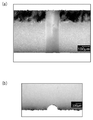
도 5는 실시예 1에 있어서 얻어진 관통 구멍의 확대상을 나타내는 도면이다.
도 6은 실시예 2에 있어서 얻어진 관통 구멍의 확대상을 나타내는 도면이다.
도 7은 실시예 3에 있어서 얻어진 관통 구멍의 확대상을 나타내는 도면이다.1 is a view schematically showing the configuration of the
2 is a view for explaining the role of the
3 is a view schematically showing the shape of the laser beam LB during the trepanning process by the
4 is a schematic cross-sectional view showing the progress of taperless processing, which is realized by performing a trepanning process in the
5 is a view showing an enlarged image of a through hole obtained in Example 1. FIG.
6 is a view showing an enlarged image of a through hole obtained in Example 2.
7 is a view showing an enlarged image of a through hole obtained in Example 3.
(발명을 실시하기 위한 형태)(Form for carrying out the invention)
<가공 장치의 개요><Overview of processing equipment>
도 1은, 본 실시 형태에 따른 트레패닝 가공을 행하기 위한 가공 장치(100)의 구성을 개략적으로 나타내는 도면이다. 가공 장치(100)는, 레이저광(LB)의 출사원(10)과, 빔 로테이터(20)와, 갈바노 스캐너(30)와, fθ 렌즈(40)와, 장치 각부의 동작을 제어하는 제어 모듈(50)과, 피가공물(이하, 워크라고도 칭함)(W)이 올려놓이는 스테이지(70)를 주로 구비한다.1 is a diagram schematically showing a configuration of a
가공 장치(100)에 있어서는, 개략, 출사원(10)으로부터 스테이지(70)에 올려놓인 워크(W)에 이르는 레이저광(LB)의 광로에 있어서, 빔 로테이터(20)와 갈바노 스캐너(30)와 fθ 렌즈(40)가 출사원(10)의 측으로부터 이 순서로 설치되어 이루어진다. 그리고, 제어 모듈(50)의 제어 아래, 출사원(10)으로부터 출사되고, 빔 로테이터(20), 갈바노 스캐너(30) 및, fθ 렌즈(40)를 순차적으로 거친 레이저광(LB)이, 워크(W)에 조사됨으로써, 워크(W)의 가공이 진행된다. 또한, 도 1에 있어서는, 출사원(10)과 빔 로테이터(20)의 사이 및, 빔 로테이터(20)와 갈바노 스캐너(30)의 사이에 각각 미러(61 및 62)가 설치되고, 이들 미러(61 및 62)에 의해 레이저광(LB)을 반사시킴으로써, 레이저광(LB)의 광로가 굽혀져 있지만, 이는 도시의 형편에 따르는 것으로서, 필수의 태양은 아니다. 혹은, 가공 장치(100)의 구성의 형편상, 더욱 많은 미러가 이용되어, 레이저광(LB)의 광로가 더욱 굽혀지는 태양이라도 좋다.In the
제어 모듈(50)은, 출사원(10)으로부터의 레이저광(LB)의 출사의 on/off 동작이나, 빔 로테이터(20)의 회전 동작이나, 갈바노 스캐너(30)의 도시하지 않는 갈바노 미러의 회전(혹은 요동) 동작이나, 스테이지(70)의 승강 동작 등을 제어한다.The
스테이지(70)는, 가공 시에 워크(W)가 재치(載置) 고정되는 부위이다. 스테이지(70)에 올려놓인 워크(W)에 대하여, 상방에 위치하는 fθ 렌즈(40)로부터 레이저광(LB)이 조사된다. 스테이지(70)는, 적어도 연직 방향으로 승강이 자유롭게 설치되어 이루어지고, 제어 모듈(50)로부터의 구동 신호에 응답하여, 승강된다. 혹은 추가로, 수평면 내에 있어서의 2축 이동(병진) 동작이나 회전 동작을 행할 수 있도록 구성되어 이루어지는 태양이라도 좋다. 이러한 경우에는, 이들 동작도, 제어 모듈(50)로부터의 구동 신호에 응답하여 이루어지게 된다.The
레이저광(LB)으로서는, 워크(W)의 재질이나 두께, 소망하는 가공 태양 등에 따른 여러 가지의 파장의 것이 선택되어도 좋고, 출사원(10)도, 선택된 레이저광(LB)을 출사 가능한 것이 준비되면 좋다.As the laser light LB, those of various wavelengths may be selected depending on the material or thickness of the work W, the desired processing mode, etc., and the
도 2는, 빔 로테이터(20) 및 fθ 렌즈(40)의 역할을 설명하기 위한 도면이다. 또한, 도 2에 있어서는, 설명의 간단함을 위해, 본래는 빔 로테이터(20)와 fθ 렌즈(40)의 사이의 광로상에 설치되는 갈바노 스캐너(30)를 생략하고 있다. 또한, 레이저광(LB)이 빔 로테이터(20)에(보다 상세하게는 프리즘(21)에) 입사할 때의 입사 방향을 축(AX1)으로 한다.2 is a view for explaining the roles of the
도 2에 나타내는 바와 같이, 빔 로테이터(20)는, 한 쌍의 프리즘(21, 22)이 중공 모터(23)의 내부에 조입된 구성을 갖는다. 한 쌍의 프리즘(21, 22)은, 프리즘(21)에 대하여 축(AX1)을 따라 입사한 레이저광(LB)이 당해 축(AX1)에 평행하게 소정 거리 시프트한 위치에 있어서, 프리즘(22)으로부터 출사되도록, 중공 모터(23)에 조입되어 이루어진다. 환언하면, 한 쌍의 프리즘(21, 22)은, 빔 로테이터(20)로부터의 출사 시의 레이저광(LB)의 광로 위치가, 당해 빔 로테이터(20)에 대한 입사 시의 레이저광(LB)의 광로 위치로부터 소정 거리 시프트하도록, 중공 모터(23) 내에 조입되어 이루어진다.As shown in Fig. 2, the
보다 상세하게는, 프리즘(21)으로부터 프리즘(22)을 향하는 레이저광(LB)은 일단, 축(AX1)에 대하여 소정의 각도 α만큼 경사지지만, 프리즘(22)으로부터(요컨대 빔 로테이터(20)로부터) 외부에 출사될 때의 레이저광(LB)의 출사 방향은, 축(AX1)에 평행하게 되어 있다.More specifically, the laser light LB from the
이에 더하여, 빔 로테이터(20)에 있어서는, 중공 모터(23)가 화살표 AR2에 나타내는 바와 같이 축(AX1)을 회전축으로 하여 회전하도록 되어 있다. 이러한 회전과 전술의 시프트의 조합의 결과, 빔 로테이터(20)로부터의 레이저광(LB)의 출사는, 축(AX1)과 평행하게 또한 축(AX1)의 주위를 회전하는 태양으로 이루어지게 된다.In addition, in the
갈바노 스캐너(30)의 기여를 무시하면(혹은, 갈바노 스캐너(30)가 레이저광(LB)의 위치를 변경하지 않는다고 하면), 빔 로테이터(20)로부터 출사된 레이저광(LB)은, 축(AX1)과 평행한 상태를 유지하여, 축(AX1)을 축 중심으로 하여 배치되어 이루어지는 fθ 렌즈(40)에 입사하게 된다. fθ 렌즈(40)는, 입사한 레이저광(LB)을 워크(W)에 있어서의 축(AX1)의 연장선상의 위치를 향하여 편향하도록, 설치되어 이루어진다. 이에 따라, 레이저광(LB)은, 소정의 입사각(β)으로 워크(W)에 조사되게 된다.If the contribution of the
단, 전술과 같이 빔 로테이터(20)는 회전하고 있다. 그렇기 때문에, fθ 렌즈(40)에 대한 레이저광(LB)의 입사 위치도 축(AX1) 주위로 회전하고, 이에 따라 fθ 렌즈(40)로부터의 레이저광(LB)의 출사 위치도 축(AX1) 주위로 회전하게 된다. 그러나, 빔 로테이터(20)에 의해 시프트되는 레이저광(LB)의 광로 위치는 축(AX1)에 대하여 등방적이기 때문에, 레이저광(LB)은 워크(W)의 동일 위치에 조사된다.However, as described above, the
이상은 즉, 빔 로테이터(20)와 fθ 렌즈(40)는, 갈바노 스캐너(30)의 기여를 무시하면, 레이저광(LB)을, 워크(W)의 동일 위치에 대하여 소정의 입사각(β)을 유지하면서 회전시키면서 입사시키는 작용을 갖고 있는 것을 의미한다. 환언하면, 빔 로테이터(20)와 fθ 렌즈(40)는, 조사 위치에 대한 레이저광(LB)의 입사의 방향을 끊임없이 다르게 하는 회전시키는 작용을 갖고 있다고도 할 수 있다.That is, the
또한, 실제의 가공 장치(100)에 있어서는, 전술과 같이, 빔 로테이터(20)와 fθ 렌즈(40)의 사이의 광로상에 갈바노 스캐너(30)가 설치되어 있다. 갈바노 스캐너(30)는, 제어 모듈(50)의 제어 아래, 워크(W)에 대한 레이저광(LB)의 조사 위치를 도 1에 있어서 화살표 AR1로 나타내는 바와 같이 임의의 위치로 변위시키기 위해 설치되어 이루어진다. 보다 상세하게는, 갈바노 스캐너(30)는, 레이저광(LB)의 조사 위치를 수평 2축 방향의 소정 범위에 변위가 자유롭게 설치되어 이루어진다. 그리고, 이러한 갈바노 스캐너(30)가 동작함으로써, 레이저광(LB)에 의한 워크(W)의 주사가 가능하게 되어 있다. 이러한 경우에 있어서, 갈바노 스캐너(30)에 의한 레이저광(LB)의 조사 위치의 변위(요컨대 레이저광(LB)에 의한 주사)는, 축(AX1)을 가상적으로, 원래의 위치(빔 로테이터(20)에 레이저광(LB)이 입사할 때의 위치)와 평행한 위치로 변위시키는 것으로 간주할 수 있다. 그렇기 때문에, 레이저광(LB)의 조사는, 갈바노 스캐너(30)의 동작에 따른 조사 위치의 변위와, 전술한 빔 로테이터(20)와 fθ 렌즈(40)의 작용에 의해 실현되는, 입사각(β)을 유지한 회전을 하면서의 당해 조사 위치로의 입사와의 조합에 의해, 이루어지게 된다.In addition, in the
<트레패닝 가공><Trepaning processing>
다음으로, 전술한 구성을 갖는 가공 장치(100)에 의한 트레패닝 가공에 대해서 설명한다. 도 3은, 가공 장치(100)에 의한 트레패닝 가공 시의, 레이저광(LB)의 모양을 개략적으로 나타내는 도면이다. 도 4는, 가공 장치(100)에 있어서 트레패닝 가공을 행함으로써 실현되는, 테이퍼리스한 천공 가공(이하, 간단히 테이퍼리스 가공이라고도 칭함)의 진행의 모양을 나타내는 개략 단면도이다.Next, the trepanning process by the
이하에 있어서는, 설명의 간단함을 위해, 도 3에 화살표 AR4로 나타내는 바와 같이, 레이저광(LB)의 조사 위치를(대표적으로는 집광점(F)을) 소정의 수평인 원(C)을 따라 변위(주회)시키는 태양으로, 즉, 레이저광(LB)에 의한 주사 궤적이 원(C)이 되는 태양으로, 트레패닝 가공이 이루어지는 경우를 대상으로 한다.In the following, for the sake of simplicity, as shown by arrow AR4 in FIG. 3, the irradiation position of the laser light LB (typically the converging point F) is a predetermined horizontal circle C. It is a case in which the trepanning process is performed in a manner in which displacement (circumference) is performed accordingly, that is, a scanning path by the laser light LB becomes a circle C.
레이저광(LB)의 원(C)을 따른 변위(주회 주사)는, 제어 모듈(50)로부터의 주사 신호에 기초하여 갈바노 스캐너(30)가 구동됨으로써 실현된다. 그리고, 본 실시 형태에 따른 가공 장치(100)에 있어서는, 이 갈바노 스캐너(30)에 의한 레이저광(LB)의 원(C)을 따른 변위에, 도 3에 있어서 화살표 AR3으로 나타내는 바와 같은 빔 로테이터(20)의 회전에 의한 레이저광(LB)의 조사의 방향의 변화를 동기시킨 상태에서, 트레패닝 가공을 행하도록 되어 있다.The displacement (circular scanning) along the circle C of the laser beam LB is realized by driving the
또한, 실제의 가공 시에는, 빔 로테이터(20)와 갈바노 스캐너(30)의 동기가 성립한 상태에서, 제어 모듈(50)이 출사원(10)에 대하여 레이저광(LB)의 출사의 on 신호를 발하고, 출사원(10)은 이에 응답하여 레이저광(LB)의 출사를 개시한다.In addition, in actual processing, in a state in which the synchronization of the
보다 상세하게는, 빔 로테이터(20)의 동작에 의해 조사 위치에 대한 레이저광(LB)의 조사 방향이 1회전하는 동안에, 갈바노 스캐너(30)에 의해 레이저광(LB)이 원(C) 상을 정확히 1회전하도록, 양자의 동작이 동기 제어된다. 이는, 중공 모터(23)가 1회전할 때마다 빔 로테이터(20)가 발하는 타이밍 신호를 제어 모듈(50)이 수취하는 타이밍에 따라서, 제어 모듈(50)이, 갈바노 스캐너(30)에 대하여, 원(C) 상을 1주하는 주사를 실행시키기 위한 주사 신호를 부여함으로써 실현된다.More specifically, while the irradiation direction of the laser light LB with respect to the irradiation position is rotated by one rotation by the operation of the
이러한 경우, 레이저광(LB)은, 원(C) 상에 있어서 원(C)을 포함하는 수평면에 대하여 직교하는 가상축(AX2)을 중심축으로 하는 원추형의 포락면(CF) 내에서 회전하면서, 원(C)을 따라 이동하게 된다. 그리고, 원(C) 상에 있어서의 레이저광(LB)의 조사 위치와, 포락면(CF) 내에서의 회전 위치(조사 위치로 하는 레이저광의 조사의 방향)의 관계에 의해, 트레패닝 가공 시의 관통 구멍의 형상이 정해지게 된다.In this case, the laser light LB is rotated in a conical enveloping surface CF having a virtual axis AX2 as a central axis orthogonal to the horizontal surface including the circle C on the circle C. , Will move along the circle (C). And, by the relationship between the irradiation position of the laser beam LB on the circle C and the rotational position in the envelope CF (the direction of irradiation of the laser beam as the irradiation position), during the trepanning process The shape of the through hole of is determined.
테이퍼리스 가공은, 그 대표적인 일 태양이다. 즉, 제어 모듈(50)에 의한 빔 로테이터(20)와 갈바노 스캐너(30)의 동기 제어가, fθ 렌즈(40)로부터 출사된 레이저광(LB)이 원(C) 상의 어느 위치에 있는 경우에 있어서도, 당해 레이저광(LB)의 통과 범위가 원(C)의 내측에 포함되고, 또한, 당해 통과 범위의 최외측이 원(C) 상에 있어서 원(C)을 포함하는 수평면에 대하여 직교하는 가상축(AX2)을 따르는 태양으로, 요컨대 당해 통과 범위의 최외측이 워크(W)에 대하여 수직이 되는 태양으로 행해지는 경우에는, 테이퍼리스 가공이 실현된다.The taperless processing is one representative aspect. That is, when the synchronous control of the
또한, 가상축(AX2)은, 갈바노 스캐너(30)에 의한 레이저광(LB)의 조사 위치의 변위에 수반하여 도 2에 나타내는 가상축(AX1)이 병행 이동한 것이라고도 생각할 수 있다. 그렇기 때문에, 테이퍼리스 가공은, 갈바노 스캐너(30)에 의해 이동하는 조사 위치가 원(C) 상의 어느 위치에 있는지에 의하지 않고, 레이저광(LB)의 통과 범위의 최외측과 광축이 이루는 각이 빔 로테이터(20)에 의해 실현되는 입사각(β)과 일치하는 조건으로, 레이저광(LB)이 기울여짐으로써, 실현된다고도 할 수 있다.It is also conceivable that the virtual axis AX2 has moved in parallel with the virtual axis AX1 shown in FIG. 2 with displacement of the irradiation position of the laser light LB by the
예로서, 도 4(a)에 나타내는 바와 같은, 도시를 생략하는 스테이지(70) 상에 수평으로 배치된 판 형상의 워크(W)에 대하여, 그 두께 방향을 따른 가공 예정면(P)(단면도인 도 4에 있어서는 선 형상으로 나타남)을 따라, 전술한 태양의 테이퍼리스 가공에 의해 직경(D)의 정원기둥 형상의 구멍을 뚫고자 하는 경우를 생각하면, 레이저광(LB)은 우선, 그 통과 범위의 최외측이 워크(W)에 대하여 수직이 되는 입사각(β)으로 레이저광(LB)이 입사하는 상태에서, 화살표 AR5로 나타내는 바와 같이 조사 방향이 회전되면서, 화살표 AR6으로 나타내는 바와 같이, 그 조사 위치가 가공 예정면(P)을 따라 변위된다. 단, 입사각(β)은, 레이저광의 간섭이나 반사가 일어나지 않는 각도인 것이 바람직하다. 또한, 반드시 레이저광(LB)의 통과 범위의 최외측이 워크(W)에 대하여 엄밀하게 수직일 필요는 없고, 실용상은, 수직에 가까운 각도이면 좋다.As an example, as shown in Fig. 4(a), for a plate-shaped work W horizontally disposed on the
이후는, 이러한 변위가 적어도 1주, 혹은 복수주 이루어지는 타이밍마다, 환언하면, 빔 로테이터(20)가 레이저광(LB)을 1회전 혹은 복수 회전시키는 타이밍마다, 제어 모듈(50)로부터의 구동 신호에 응답하여 스테이지(70)가 동작함으로써, 워크(W)가 소정 거리 상승된다. 이에 따라, 두께 방향에 있어서 집광점(F)이 워크(W)의 내부에 들어가, 도 4(b)에 나타내는 바와 같이, 워크(W)에는, 표면으로부터 두께 방향을 향하여, 가공 예정면(P)을 따른 가공 홈(가공 흔적)(G)이 서서히 형성되어 가게 된다. 이때, 레이저광(LB)의 기울기나 회전의 방법은, 가공 개시 시인 채이고, 그렇기 때문에, 레이저광(LB)이 가공 예정면(P)의 밖으로는 비어져 나오는 일은 없다. 또한, 워크(W)의 상승의 타이밍은, 워크(W)의 재질, 레이저광(LB)의 강도 등에 따라서 적절하게 정해져도 좋다.Subsequently, at each timing at which such displacement is at least one week or multiple weeks, in other words, at each timing at which the
또한, 스테이지(70)의 승강은, fθ 렌즈(40)와의 상대적인 승강이면 좋고, 스테이지(70)의 승강을 대신하여, 혹은 스테이지(70)의 승강과 아울러, fθ 렌즈(40)를 포함하는 광학계를 당해 광학계 내의 광학적 거리를 바꾸는 일 없이 승강시키는 태양이라도 좋다.In addition, the elevation of the
혹은, 갈바노 스캐너(30)의 동작에 의한 레이저광(LB)의 주회 주사와, 스테이지(70)의 동작에 의한 워크(W)의 상승이, 동기적으로 행해지는 태양이라도 좋다. 이러한 경우, 레이저광(LB)의 집광점(F)은, 나선 형상의 궤적을 그리면서 워크(W)의 내부에 들어가게 된다.Alternatively, a mode in which the scan of the laser light LB by the operation of the
레이저광(LB)의 주회 주사와 워크(W)의 상승이 반복됨으로써, 최종적으로는, 도 4(c)에 나타내는 바와 같이, 홈(G)이, 가공 예정면(P)을 따라 워크(W)를 관통한다. 그리고, 화살표 AR7로 나타내는 바와 같이 홈(G)으로 둘러싸인 원기둥 형상의 부분을 이탈시키면, 도 4(d)에 나타내는 바와 같이, 측면(S)이 워크(W)의 표면(Wa)과 이면(Wb)의 쌍방에 대하여 수직인 관통 구멍(H)이 형성된다. 요컨대, 테이퍼리스 가공이 완료된다.As the scanning of the laser beam LB and the rise of the work W are repeated, finally, as shown in Fig. 4(c), the groove G follows the work surface P to be processed (W). ). Then, as shown by the arrow AR7, when the part of the cylindrical shape surrounded by the groove G is separated, as shown in Fig. 4(d), the side surface S is the front surface Wa and the back surface Wb of the work W. ) A through hole H perpendicular to both sides is formed. In short, taperless processing is completed.
또한, 워크(W)의 두께가 얇은 경우에는, 이와 같이 스테이지(70)를 동작시켜 워크(W)를 상방으로 이동시키지 않고도, 홈(G)을 가공 예정면(P)을 따라 표면(Wa)으로부터 이면(Wb)으로 관통시키는 것이 가능하다.In addition, when the thickness of the work W is thin, the surface Wa is moved along the planned surface P of the groove G without moving the work W upward by operating the
그런데, 원기둥 형상의 관통 구멍을 뚫는 경우에는 레이저광(LB)의 주사 궤적을 원으로 할 필요가 있지만, 주사 궤적이 이루는 폐곡선(다각형 포함함)의 형상을 다르게 함으로써, 다른 형상의 관통 구멍을 뚫는 것도 가능하다. 예를 들면, 레이저광(LB)에 의한 주사 궤적이 직사각형 형상이 되도록 갈바노 스캐너(30)를 제어하면, 직사각형의 관통 구멍을 형성하는 가공도 가능하고, 그때에, 레이저광(LB)의 통과 범위의 최외측이 워크(W)에 대하여 수직이 되는 입사각으로 레이저광(LB)을 워크(W)에 입사시킨다는 관계를 충족시키도록 하면, 이러한 직사각형의 관통 구멍을 테이퍼리스로 하는 것도 가능하다.However, in the case of drilling a through hole having a cylindrical shape, it is necessary to make the scanning trajectory of the laser light LB a circle, but by making the shape of the closed curve (including a polygon) formed by the scanning trajectory different, a through hole of another shape is drilled. It is also possible. For example, if the
이상, 설명한 바와 같이, 본 실시 형태에 의하면, 출사원으로부터 피가공물에 이르는 레이저광의 광로에 있어서, 빔 로테이터와 갈바노 스캐너와 fθ 렌즈가 이 순서로 설치된 가공 장치에 있어서, 갈바노 스캐너에 의해, 조사 위치가 예를 들면 원 등의 폐곡선이 주사 궤적이 되도록 레이저광을 변위시키는 동작과, 빔 로테이터와 fθ 렌즈에 의해, 레이저광의 조사 방향을 기울이면서 당해 조사 방향을 회전시키는 동작을 동기시키고, 추가로, 레이저광의 통과 범위의 최외측이 피가공물에 대하여 수직이 되는 입사각으로 레이저광이 피가공물에 입사하도록 함으로써, 피가공물에 대하여 테이퍼리스한 천공 가공을 행할 수 있다.As described above, according to the present embodiment, in the optical path of the laser light from the source to the workpiece, in the processing apparatus in which the beam rotator, the galvano scanner and the fθ lens are provided in this order, by the galvano scanner, Synchronize the operation of displacing the laser light so that the irradiation position is, for example, a closed curve such as a circle as a scanning trajectory, and rotating the irradiation direction while tilting the irradiation direction of the laser light by a beam rotator and an fθ lens, and adding Thus, by making the laser light enter the work piece at an incidence angle at which the outermost side of the laser beam passing range is perpendicular to the work piece, a tapered punching process can be performed on the work piece.
<변형예><Modification>
전술의 실시 형태에 있어서는, 테이퍼리스 가공을 실현하기 위해, 레이저광의 통과 범위의 최외측이 피가공물에 대하여 수직이 되는 입사각으로 레이저광을 입사하도록 하고 있었지만, 이를 대신하여, 레이저광의 통과 범위의 최내측이 피가공물에 대하여 수직이 되는 입사각으로 레이저광을 입사시키는, 전술의 실시 형태와는 역위상이 되는 태양으로, 레이저광을 입사시킨 경우에는, 관통 구멍이 테이퍼 형상이 되는 천공 가공을, 바람직하게는, 테이퍼의 형상을 제어한 가공을, 의도적으로 행할 수 있다. 나아가서는, 레이저광의 경사 상태를, 가공 전체를 통하여, 혹은 가공의 도중에 단계적으로 또는 연속적으로 다르게 함으로써, 여러 가지의 구멍 형상의 천공 가공을 행할 수 있다. 이는 즉, 레이저광의 경사 상태를 제어함으로써, 테이퍼의 상태를 의도적으로 제어한 천공 가공을 행할 수 있는 것을 의미한다.In the above-described embodiment, in order to realize taperless processing, laser light is incident on the outermost side of the laser beam passing range at an incident angle perpendicular to the workpiece, but instead, the laser beam passing range is maximized. When the laser light is incident on the sun, which is an inverse phase from the above-described embodiment, in which the laser light is incident at an incidence angle in which the inside is perpendicular to the workpiece, a perforation processing in which the through hole is tapered is preferable. In other words, the processing in which the shape of the taper is controlled can be intentionally performed. Furthermore, various hole-shaped perforations can be performed by changing the inclined state of the laser light stepwise or continuously through the entire process or in the middle of the process. This means that, by controlling the inclined state of the laser beam, it is possible to perform a puncturing process intentionally controlling the state of the taper.
[실시예][Example]
(실시예 1)(Example 1)
본 실시예에서는 두께 0.62㎜의 알루미나 세라믹판에 대하여, 직경 200㎛의 천공 가공을 행했다. 가공 조건은 이하와 같이 했다.In this embodiment, alumina ceramic plates with a thickness of 0.62 mm were punched with a diameter of 200 µm. The processing conditions were as follows.
레이저 조건→파장=532㎚, 펄스폭<50㎰, 반복 주파수=100㎑, 출력=7.5W;Laser condition→wavelength=532nm, pulse width<50Hz, repetition frequency=100Hz, output=7.5W;
빔 로테이터 회전수=10000rpm;Beam rotator revolution=10000 rpm;
z축 이송 피치=12㎛.z-axis feed pitch=12㎛.
도 5는, 가공에 의해 얻어진 관통 구멍의 확대상을 나타내는 도면이다. 도 5(a)는 관통 구멍을 통과하는 단면으로 알루미나 세라믹판을 분단한 후, 관통 구멍을 측방으로부터 본 상이고, 도 5(b)는 이러한 분단 후의 알루미나 세라믹판의 표면의 상이다.5 is an enlarged image of a through hole obtained by processing. Fig. 5(a) is a phase in which the alumina ceramic plate is divided into sections through a through hole, and the through hole is viewed from the side, and Fig. 5(b) is an image of the surface of the alumina ceramic plate after such division.
도 5로부터는, 테이퍼리스한 관통 구멍이 양호하게 형성되어 있는 것이 확인된다.It is confirmed from FIG. 5 that the tapered through hole is satisfactorily formed.
(실시예 2)(Example 2)
본 실시예에서는 두께 0.36㎜의 SiC판에 대하여, 직경 300㎛의 천공 가공을 행했다. 가공 조건은 이하와 같이 했다.In this example, a SiC plate having a thickness of 0.36 mm was punched with a diameter of 300 µm. The processing conditions were as follows.
레이저 조건→파장=532㎚, 펄스폭<15㎱, 반복 주파수=80㎑, 출력=4.0W;Laser condition→wavelength=532nm, pulse width<15Hz, repetition frequency=80Hz, output=4.0W;
빔 로테이터 회전수=5000rpm;Beam rotator revolution=5000 rpm;
z축 이송 피치=20㎛.z-axis feed pitch=20㎛.
도 6은, 가공에 의해 얻어진 관통 구멍의 확대상을 나타내는 도면이다. 도 6(a)는 관통 구멍을 통과하는 단면으로 SiC판을 분단한 후, 관통 구멍을 측방으로부터 본 상이고, 도 6(b)는 관통 구멍 형성 후의 SiC판의 표면의 상이다.6 is a view showing an enlarged image of a through hole obtained by processing. Fig. 6(a) is a view of the SiC plate after the SiC plate is divided into sections through the through hole, and Fig. 6(b) is an image of the surface of the SiC plate after the through hole is formed.
도 6으로부터는, 테이퍼리스한 관통 구멍이 양호하게 형성되어 있는 것이 확인된다.It is confirmed from FIG. 6 that the tapered through hole is satisfactorily formed.
(실시예 3)(Example 3)
본 실시예에서는 두께 0.49㎜의 Si판에 대하여, 직경 500㎛의 천공 가공을 행했다. 가공 조건은 이하와 같이 했다.In this example, a Si plate having a thickness of 0.49 mm was bored with a diameter of 500 µm. The processing conditions were as follows.
레이저 조건→파장=532㎚, 펄스폭<15㎱, 반복 주파수=50㎑, 출력=7.5W;Laser condition→wavelength=532nm, pulse width<15Hz, repetition frequency=50Hz, output=7.5W;
빔 로테이터 회전수=5000rpm;Beam rotator revolution=5000 rpm;
z축 이송 피치=60㎛.z-axis feed pitch=60㎛.
도 7은, 가공에 의해 얻어진 관통 구멍의 확대상을 나타내는 도면이다. 도 7(a)는 관통 구멍을 통과하는 단면으로 Si판을 분단한 후, 관통 구멍을 측방으로부터 본 상이고, 도 7(b)는 관통 구멍 형성 후의 Si판의 표면의 상이다.7 is a view showing an enlarged image of a through hole obtained by processing. Fig. 7(a) is a view of the Si plate after the Si plate is divided into sections through a through hole, and Fig. 7(b) is an image of the surface of the Si plate after forming the through hole.
도 7로부터는, 테이퍼리스한 관통 구멍이 양호하게 형성되어 있는 것이 확인된다.It is confirmed from FIG. 7 that the tapered through hole is satisfactorily formed.
10 : 출사원
20 : 빔 로테이터
21, 22 : 프리즘
23 : 중공 모터
30 : 갈바노 스캐너
40 : fθ 렌즈
50 : 제어 모듈
70 : 스테이지
100 : 가공 장치
LB : 레이저광
F : 집광점
H : 관통 구멍
P : 가공 예정면
W : 워크10: employee
20: beam rotator
21, 22: Prism
23: hollow motor
30: galvano scanner
40: fθ lens
50: control module
70: stage
100: processing device
LB: laser light
F: Condensing point
H: Through hole
P: Planned surface
W: Walk
Claims (5)
상기 레이저광의 출사원과,
가공 시에 상기 피가공물이 수평으로 올려놓이는 스테이지와,
상기 출사원으로부터 상기 스테이지에 올려놓인 상기 피가공물에 이르기까지의 상기 레이저광의 광로상에, 상기 출사원의 측으로부터 순차적으로 설치된 빔 로테이터, 갈바노 스캐너 및, fθ 렌즈와,
상기 장치의 각부의 동작을 제어하는 제어 수단을 구비하고,
상기 fθ 렌즈를 거친 상기 레이저광은 상방으로부터 상기 피가공물에 조사되고,
상기 빔 로테이터는, 입사한 상기 레이저광을 입사 방향과 평행한 위치로 시프트시킴과 함께, 상기 빔 로테이터에 대한 상기 레이저광의 입사 방향을 회전축으로 하여 회전시키면서 출사하고,
상기 갈바노 스캐너는 상기 레이저광의 상기 피가공물에 있어서의 조사 위치를 변위 가능하게 설치되고,
상기 레이저광은, 상기 빔 로테이터 및 상기 갈바노 스캐너를 거친 상기 레이저광이 상기 fθ 렌즈를 거침으로써, 상기 조사 위치에 대한 입사각을 소정의 각도로 유지하면서, 상기 조사 위치에 대한 조사 방향이 회전되고,
상기 제어 수단은, 상기 갈바노 스캐너가 상기 레이저광의 상기 조사 위치를 미리 정한 폐곡선을 따라 변위시키는 동작과, 상기 빔 로테이터와 상기 fθ 렌즈에 의해, 상기 조사 위치에 대한 상기 레이저광의 상기 조사 방향을 회전시키는 동작을 동기시키는, 것을 특징으로 하는, 레이저 가공 장치.An apparatus for processing the workpiece by irradiating a laser beam to the workpiece,
The laser light source,
A stage in which the workpiece is placed horizontally during processing,
A beam rotator, a galvano scanner, and an fθ lens sequentially installed from the side of the source on the optical path of the laser light from the source to the workpiece placed on the stage;
It has a control means for controlling the operation of each part of the device,
The laser light that has passed through the fθ lens is irradiated to the workpiece from above,
The beam rotator shifts the incident laser light to a position parallel to the incident direction, and exits while rotating the incident direction of the laser light to the beam rotator as a rotation axis,
The galvano scanner is provided so that the irradiation position of the laser beam in the workpiece is displaceable,
In the laser light, the laser light that has passed through the beam rotator and the galvano scanner passes through the fθ lens, so that the irradiation direction with respect to the irradiation position is rotated while maintaining an incident angle with respect to the irradiation position at a predetermined angle. ,
The control means rotates the irradiation direction of the laser light with respect to the irradiation position by the operation of the galvano scanner to displace the irradiation position of the laser light along a predetermined closed curve, and the beam rotator and the fθ lens. A laser processing apparatus characterized by synchronizing a prescribing operation.
상기 레이저광의 통과 범위의 최외측이 상기 피가공물에 대하여 수직이 되는 입사각으로 상기 레이저광을 피가공물에 입사시키는, 것을 특징으로 하는, 레이저 가공 장치.According to claim 1,
The laser processing apparatus according to claim 1, wherein the laser light is incident on the work piece at an incident angle at which the outermost side of the laser beam passing range is perpendicular to the work piece.
상기 제어 수단은, 상기 갈바노 스캐너가 상기 레이저광의 상기 조사 위치를 미리 정한 원을 따라 1주(周)시키는 동작과, 상기 빔 로테이터와 상기 fθ 렌즈에 의해, 상기 조사 위치에 대한 상기 레이저광의 상기 조사 방향을 1회전시키는 동작을 동기시키는, 것을 특징으로 하는, 레이저 가공 장치.According to claim 2,
The control means includes: an operation in which the galvano scanner sets the irradiation position of the laser light along a predetermined circle, and by the beam rotator and the fθ lens, the laser light to the irradiation position is A laser processing apparatus characterized by synchronizing the operation of rotating the irradiation direction by one rotation.
상기 스테이지가 승강이 자유롭게 설치되어 이루어지고,
상기 제어 수단은, 상기 레이저광의 상기 조사 위치의 상기 원을 따른 변위가 1주 또는 복수주 이루어지는 타이밍마다, 상기 스테이지를 이동시켜, 상기 피가공물을 상승시키는, 것을 특징으로 하는, 레이저 가공 장치.According to claim 3,
The stage is made up and down freely installed,
The control means is characterized in that the displacement of the laser beam along the circle of the irradiation position at a timing of 1 week or multiple weeks is moved to move the stage to raise the workpiece.
상기 레이저광의 광로상에, 순차적으로 설치되게 되는 빔 로테이터, 갈바노 스캐너 및, fθ 렌즈와, 상기 빔 로테이터 유닛의 각부의 동작을 제어하는 제어 수단을 구비하고,
상기 빔 로테이터는, 입사한 상기 레이저광을 입사 방향과 평행한 위치로 시프트시킴과 함께, 상기 빔 로테이터에 대한 상기 레이저광의 입사 방향을 회전축으로 하여 회전시키면서 출사하고,
상기 갈바노 스캐너는 상기 레이저광의 상기 피가공물에 있어서의 조사 위치를 변위 가능하게 설치되고,
상기 레이저광은, 상기 빔 로테이터 및 상기 갈바노 스캐너를 거친 상기 레이저광이 상기 fθ 렌즈를 거침으로써, 상기 조사 위치에 대한 입사각을 소정의 각도로 유지하면서, 상기 조사 위치에 대한 조사 방향이 회전되고,
상기 제어 수단은, 상기 갈바노 스캐너가 상기 레이저광의 상기 조사 위치를 미리 정한 폐곡선을 따라 변위시키는 동작과, 상기 빔 로테이터와 상기 fθ 렌즈에 의해, 상기 조사 위치에 대한 상기 레이저광의 상기 조사 방향을 회전시키는 동작을 동기시키는, 것을 특징으로 하는, 빔 로테이터 유닛.A beam rotator unit used in an apparatus for processing the workpiece by irradiating a laser beam onto the workpiece,
A beam rotator, a galvano scanner, and an fθ lens that are sequentially installed on the optical path of the laser light, and control means for controlling the operation of each part of the beam rotator unit,
The beam rotator shifts the incident laser light to a position parallel to the incident direction, and exits while rotating the incident direction of the laser light to the beam rotator as a rotation axis,
The galvano scanner is provided so that the irradiation position of the laser beam in the workpiece is displaceable,
In the laser light, the laser light that has passed through the beam rotator and the galvano scanner passes through the fθ lens, so that the irradiation direction with respect to the irradiation position is rotated while maintaining an incident angle with respect to the irradiation position at a predetermined angle. ,
The control means rotates the irradiation direction of the laser light with respect to the irradiation position by the operation of the galvano scanner to displace the irradiation position of the laser light along a predetermined closed curve, and the beam rotator and the fθ lens. Beam rotator unit, characterized in that, to synchronize the operation.
Applications Claiming Priority (2)
| Application Number | Priority Date | Filing Date | Title |
|---|---|---|---|
| JP2018247992A JP2020104167A (en) | 2018-12-28 | 2018-12-28 | Laser processing device and beam rotator unit |
| JPJP-P-2018-247992 | 2018-12-28 |
Publications (1)
| Publication Number | Publication Date |
|---|---|
| KR20200083249A true KR20200083249A (en) | 2020-07-08 |
Family
ID=71213420
Family Applications (1)
| Application Number | Title | Priority Date | Filing Date |
|---|---|---|---|
| KR1020190171358A KR20200083249A (en) | 2018-12-28 | 2019-12-20 | Beam rotator unit and laser processing apparatus |
Country Status (4)
| Country | Link |
|---|---|
| JP (1) | JP2020104167A (en) |
| KR (1) | KR20200083249A (en) |
| CN (1) | CN111375913A (en) |
| TW (1) | TW202035054A (en) |
Cited By (2)
| Publication number | Priority date | Publication date | Assignee | Title |
|---|---|---|---|---|
| CN112846517A (en) * | 2020-12-31 | 2021-05-28 | 武汉华工激光工程有限责任公司 | Device and method for removing coating on inner wall of porous structure of filter |
| CN113909698A (en) * | 2021-10-26 | 2022-01-11 | 之江实验室 | Parallel interpenetration high-speed laser direct writing photoetching method and device |
Families Citing this family (3)
| Publication number | Priority date | Publication date | Assignee | Title |
|---|---|---|---|---|
| JP7427248B2 (en) | 2020-07-21 | 2024-02-05 | Uht株式会社 | Laser processing method and laser processing equipment |
| CN112059409B (en) * | 2020-08-31 | 2022-06-21 | 深圳泰德激光技术股份有限公司 | Laser drilling device |
| JP7274807B1 (en) | 2023-01-31 | 2023-05-17 | 国立大学法人 名古屋工業大学 | LASER PROCESSING DEVICE, LASER PROCESSING METHOD AND PROGRAM |
Citations (1)
| Publication number | Priority date | Publication date | Assignee | Title |
|---|---|---|---|---|
| JP2014133242A (en) | 2013-01-09 | 2014-07-24 | Lps Works Co Ltd | Laser processing method and laser processing device |
Family Cites Families (5)
| Publication number | Priority date | Publication date | Assignee | Title |
|---|---|---|---|---|
| JPH04237585A (en) * | 1991-01-23 | 1992-08-26 | Hitachi Constr Mach Co Ltd | Laser cutter and laser cutting method |
| TWI221102B (en) * | 2002-08-30 | 2004-09-21 | Sumitomo Heavy Industries | Laser material processing method and processing device |
| JP4386137B2 (en) * | 2008-02-29 | 2009-12-16 | トヨタ自動車株式会社 | Laser processing apparatus and laser processing method |
| JP5922906B2 (en) * | 2011-10-18 | 2016-05-24 | 三星ダイヤモンド工業株式会社 | Glass substrate processing equipment by laser beam |
| CN104162741B (en) * | 2014-07-31 | 2016-06-01 | 北京万恒镭特机电设备有限公司 | Laser processing device and method thereof |
-
2018
- 2018-12-28 JP JP2018247992A patent/JP2020104167A/en active Pending
-
2019
- 2019-12-17 TW TW108146146A patent/TW202035054A/en unknown
- 2019-12-20 KR KR1020190171358A patent/KR20200083249A/en unknown
- 2019-12-20 CN CN201911326219.XA patent/CN111375913A/en not_active Withdrawn
Patent Citations (1)
| Publication number | Priority date | Publication date | Assignee | Title |
|---|---|---|---|---|
| JP2014133242A (en) | 2013-01-09 | 2014-07-24 | Lps Works Co Ltd | Laser processing method and laser processing device |
Cited By (2)
| Publication number | Priority date | Publication date | Assignee | Title |
|---|---|---|---|---|
| CN112846517A (en) * | 2020-12-31 | 2021-05-28 | 武汉华工激光工程有限责任公司 | Device and method for removing coating on inner wall of porous structure of filter |
| CN113909698A (en) * | 2021-10-26 | 2022-01-11 | 之江实验室 | Parallel interpenetration high-speed laser direct writing photoetching method and device |
Also Published As
| Publication number | Publication date |
|---|---|
| CN111375913A (en) | 2020-07-07 |
| JP2020104167A (en) | 2020-07-09 |
| TW202035054A (en) | 2020-10-01 |
Similar Documents
| Publication | Publication Date | Title |
|---|---|---|
| KR20200083249A (en) | Beam rotator unit and laser processing apparatus | |
| KR102584490B1 (en) | Laser processing method and device for transparent materials | |
| CN102649199B (en) | Substrate processing device and substrate processing method | |
| US8933374B2 (en) | Pulse laser machining apparatus and pulse laser machining method | |
| US20140263212A1 (en) | Coordination of beam angle and workpiece movement for taper control | |
| US20110318877A1 (en) | Dicing methods | |
| CA2560238A1 (en) | Laser-based ablation method and optical system | |
| CN106425122A (en) | Device and method for laser rotary-cut processing | |
| JP5634765B2 (en) | Pulse laser machining method and pulse laser machining data creation method | |
| US20180136458A1 (en) | System for deflecting an optical radiation beam and device comprising this system | |
| TW202045289A (en) | Laser hole drilling apparatus and method | |
| US20100102045A1 (en) | Method of cutting parts to be machined using a pulsed laser | |
| EP3954492A1 (en) | Laser machining device, laser machining system, rotator unit device, laser machining method, and probe card production method | |
| JP5901265B2 (en) | Pulse laser processing apparatus and pulse laser processing method | |
| JPH06320296A (en) | Laser beam machine and laser beam machining method | |
| JP2004174539A (en) | Laser beam machining method | |
| KR102311128B1 (en) | Method and apparatus for laser processing substrate of brittle material | |
| JP5909351B2 (en) | Pulse laser processing apparatus and pulse laser processing method | |
| JP2009269084A (en) | Beam decentering optical system for laser beam machine | |
| JP2004209508A (en) | Laser beam machining method and laser beam machining device | |
| TWI409121B (en) | Method and device for mine clearance | |
| JP2003188446A (en) | Method for stabilizing pulse for laser processing | |
| JP7144119B2 (en) | LASER PROCESSING DEVICE AND METHOD OF PROCESSING LONG WORKED WORK WITH LASER PROCESSING DEVICE | |
| KR102353478B1 (en) | Method and apparatus for laser processing substrate of brittle material | |
| KR102042992B1 (en) | Laser optical system |