KR20200078582A - Multi-material mirror system - Google Patents
Multi-material mirror system Download PDFInfo
- Publication number
- KR20200078582A KR20200078582A KR1020207015050A KR20207015050A KR20200078582A KR 20200078582 A KR20200078582 A KR 20200078582A KR 1020207015050 A KR1020207015050 A KR 1020207015050A KR 20207015050 A KR20207015050 A KR 20207015050A KR 20200078582 A KR20200078582 A KR 20200078582A
- Authority
- KR
- South Korea
- Prior art keywords
- mirror
- cte
- strut
- extension member
- containing device
- Prior art date
Links
Images


Classifications
-
- G—PHYSICS
- G02—OPTICS
- G02B—OPTICAL ELEMENTS, SYSTEMS OR APPARATUS
- G02B7/00—Mountings, adjusting means, or light-tight connections, for optical elements
- G02B7/18—Mountings, adjusting means, or light-tight connections, for optical elements for prisms; for mirrors
- G02B7/181—Mountings, adjusting means, or light-tight connections, for optical elements for prisms; for mirrors with means for compensating for changes in temperature or for controlling the temperature; thermal stabilisation
-
- G—PHYSICS
- G02—OPTICS
- G02B—OPTICAL ELEMENTS, SYSTEMS OR APPARATUS
- G02B17/00—Systems with reflecting surfaces, with or without refracting elements
- G02B17/02—Catoptric systems, e.g. image erecting and reversing system
- G02B17/06—Catoptric systems, e.g. image erecting and reversing system using mirrors only, i.e. having only one curved mirror
- G02B17/0605—Catoptric systems, e.g. image erecting and reversing system using mirrors only, i.e. having only one curved mirror using two curved mirrors
- G02B17/061—Catoptric systems, e.g. image erecting and reversing system using mirrors only, i.e. having only one curved mirror using two curved mirrors on-axis systems with at least one of the mirrors having a central aperture
-
- G—PHYSICS
- G02—OPTICS
- G02B—OPTICAL ELEMENTS, SYSTEMS OR APPARATUS
- G02B23/00—Telescopes, e.g. binoculars; Periscopes; Instruments for viewing the inside of hollow bodies; Viewfinders; Optical aiming or sighting devices
- G02B23/16—Housings; Caps; Mountings; Supports, e.g. with counterweight
-
- G—PHYSICS
- G02—OPTICS
- G02B—OPTICAL ELEMENTS, SYSTEMS OR APPARATUS
- G02B7/00—Mountings, adjusting means, or light-tight connections, for optical elements
- G02B7/008—Mountings, adjusting means, or light-tight connections, for optical elements with means for compensating for changes in temperature or for controlling the temperature; thermal stabilisation
-
- G—PHYSICS
- G02—OPTICS
- G02B—OPTICAL ELEMENTS, SYSTEMS OR APPARATUS
- G02B7/00—Mountings, adjusting means, or light-tight connections, for optical elements
- G02B7/18—Mountings, adjusting means, or light-tight connections, for optical elements for prisms; for mirrors
- G02B7/182—Mountings, adjusting means, or light-tight connections, for optical elements for prisms; for mirrors for mirrors
- G02B7/183—Mountings, adjusting means, or light-tight connections, for optical elements for prisms; for mirrors for mirrors specially adapted for very large mirrors, e.g. for astronomy, or solar concentrators
Abstract
제1 미러와 열팽창 계수가 다른 제2 미러를 포함하는 미러 시스템. 음의 CTE 스트럿은 본체부, 본체부 주위에서 서로 대향하여 배치되고 스트럿 길이를 정의하는 제1 결합부 및 제2 결합부를 포함할 수 있다. 제1 및 제2 결합부는 각각 외부 구조와 인터페이스 할 수 있다. 음의 CTE 스트럿은 본체부에 결합된 제1 단부 및 중간 연장 부재에 의해 제1 결합부에 결합된 제2 단부를 갖는 오프셋 연장 부재를 포함할 수 있다. 제1 및 제2 단부는 스트럿 길이에 평행한 오프셋 길이를 정의할 수 있다. 음의 CTE 스트럿이 온도가 상승하면, 오프셋 길이는 스트럿 길이를 감소시키기에 충분한 오프셋 연장 부재의 열 팽창으로 인해 증가하도록 구성될 수 있다.A mirror system comprising a first mirror and a second mirror having a different coefficient of thermal expansion. The negative CTE strut may include a body portion, first coupling portions and second coupling portions disposed opposite to each other around the body portion and defining a strut length. The first and second coupling units may interface with the external structure, respectively. The negative CTE strut may include an offset extension member having a first end coupled to the body portion and a second end coupled to the first engagement portion by an intermediate extension member. The first and second ends can define an offset length parallel to the strut length. When the temperature of the negative CTE strut rises, the offset length can be configured to increase due to the thermal expansion of the offset extension member sufficient to reduce the strut length.
Description
본 발명은 다중 재료 미러 시스템에 관한 것이다.The present invention relates to a multi-material mirror system.
위성에서 일반적으로 발견되는 우주 기반 망원경의 카세그레인 반사기 타입 이미징 시스템(Cassegrain reflector-type imaging system)은 이미지 품질을 저하시킬 수 있는 환경(예를 들어, 온도) 변화에 취약하다. 따라서, 이러한 이미징 시스템에 사용되는 미러 시스템은 환경 변화에 대한 감도를 줄이도록 설계되었다. 하나의 전형적인 미러 시스템 설계는 모든 광학(예를 들어, 초저 팽창(ultra-low expansion)(ULE) 유리 미러) 및 광학 시스템의 지지 구조물에 대해 0(zero)에 가까운 열 팽창 계수(CTE) 재료를 이용한다. 이 디자인은 환경 변화에 효과적으로 영향을 받지 않는다. 다른 전형적인 미러 시스템 설계는 광학 시스템의 모든 광학 및 모든 지지 구조물에 대해 비교적 높은 CTE 실리콘 카바이드(SiC)를 사용한다. SiC 재료는 열팽창에 취약하지만, 시스템의 모든 구성 요소에 대한 균일한 CTE는 열 보상 및/또는 활성 온도 제어를 통합할 때 환경 변화에 대한 민감도를 줄이는 데 다소 효과적이다.The space-based telescope's Casegrain reflector-type imaging system, commonly found on satellites, is vulnerable to changes in the environment (eg, temperature) that can degrade image quality. Therefore, the mirror system used in such an imaging system is designed to reduce the sensitivity to environmental changes. One typical mirror system design provides a near zero coefficient of thermal expansion (CTE) material for all optical (e.g., ultra-low expansion (ULE) glass mirrors) and support structures of optical systems. To use. The design is not effectively affected by environmental changes. Other typical mirror system designs use relatively high CTE silicon carbide (SiC) for all optics and all support structures in the optical system. SiC materials are susceptible to thermal expansion, but uniform CTEs for all components of the system are somewhat effective in reducing sensitivity to environmental changes when integrating thermal compensation and/or active temperature control.
본 발명은 다중 재료 미러 시스템에 관한 것이다.The present invention relates to a multi-material mirror system.
본 발명의 특징 및 장점은 첨부 도면과 함께 다음의 상세한 설명으로부터 명백해질 것이며, 이는 함께 본 발명의 특징을 예시하며; 그리고, 여기서:
도 1은 본 개시의 예에 따른 미러 시스템의 예시이다.
도 2는 본 개시의 예에 따른 음의 CTE 스트럿의 예시이다.
도 3a 및 3b는 본 개시의 예에 따라, 양의 CTE 제1 미러로 도 2의 음의 CTE 스트럿의 동작을 도시한다.
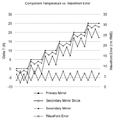
도 4는 본 개시의 예에 따른 미러 시스템에 의해 달성될 수 있는 구성 요소 온도 및 이미지 품질의 그래프이다.
이제 도시된 예시적인 실시예를 참조할 것이며, 이를 설명하기 위해 특정 용어가 사용될 것이다. 그럼에도 불구하고, 본 발명의 범위의 제한이 의도되지 않는다는 것이 이해될 것이다.Features and advantages of the present invention will become apparent from the following detailed description in conjunction with the accompanying drawings, which together illustrate the features of the present invention; And, here:
1 is an illustration of a mirror system according to an example of the present disclosure.
2 is an illustration of a negative CTE strut according to an example of the present disclosure.
3A and 3B illustrate the operation of the negative CTE strut of FIG. 2 with a positive CTE first mirror, according to an example of the present disclosure.
4 is a graph of component temperature and image quality that can be achieved by a mirror system according to an example of the present disclosure.
Reference will now be made to the exemplary embodiment shown, and specific terms will be used to describe it. It will nevertheless be understood that no limitation of the scope of the invention is intended.
본원에서 사용되는 용어 "실질적으로(substantially)"는 작용, 특성, 속성, 상태, 구조, 항목 또는 결과의 완전하거나 거의 완전한 범위 또는 정도를 의미한다. 예를 들어, "실질적으로"에 에워싸인 개체는 개체가 완전히 에워싸이거나 거의 완전히 에워싸여 있음을 의미한다. 절대 완전성으로부터의 정확히 허용되는 편차의 정도는 경우에 따라 특정 상황에 따라 달라질 수 있다. 그러나, 일반적으로 완료의 근접성은 절대 및 전체 완료가 얻은 것처럼 동일한 전체 결과를 갖도록 한다. “실질적으로"의 사용은 작용, 특성, 속성, 상태, 구조, 항목 또는 결과의 완전하거나 거의 완전한 작용의 결여를 언급하기 위해 부정적인 의미로 사용될 때에도 동일하게 적용된다.As used herein, the term "substantially" refers to the complete or near complete extent or extent of an action, property, attribute, state, structure, item or result. For example, an "substantially" enclosed entity means that the entity is either completely enclosed or almost completely enclosed. The extent of the exact permissible deviation from absolute completeness may in some cases depend on the particular situation. However, in general, the proximity of completion ensures that the absolute and total completions have the same overall result as obtained. The use of “substantially” applies equally when used in a negative sense to refer to the lack of a complete or almost complete action of an action, characteristic, attribute, state, structure, item or result.
본원에서 사용된 "인접한(adjacent)"은 두 구조 또는 요소의 근접성을 지칭한다. 특히, "인접한" 것으로 식별된 요소는 인접하거나 연결될 수 있다. 이러한 요소는 또한 반드시 서로 접촉하지 않고 서로 가까이 또는 가까이 있을 수 있다. 정확한 근접성의 정도는 경우에 따라 특정 상황에 따라 달라질 수 있다.As used herein, "adjacent" refers to the proximity of two structures or elements. In particular, elements identified as "adjacent" may be contiguous or connected. These elements may also be close to or close to each other without necessarily contacting each other. The exact degree of proximity may vary from case to case.
본 발명의 개념의 기초 개요가 아래에 제공되고, 구체적인 예는 나중에 더 상세히 설명된다. 이 초기 요약은 독자들이 예를 더 빨리 이해하는 것을 돕기 위해 의도된 것이지만, 예의 주요 특징 또는 필수 특징을 식별하기 위한 것이 아니며 청구된 주제의 범위를 제한하려는 것이 아니다.A basic overview of the inventive concept is provided below, and specific examples are described in more detail later. This initial summary is intended to help readers understand the examples faster, but it is not intended to identify key features or essential features of the examples and is not intended to limit the scope of the claimed subject matter.
거의 0에 가까운 모든 CTE 구성 요소를 통합한 미러 시스템 설계가 환경 변화에 대한 민감도를 제거하는 데 효과적이지만, ULE 유리 미러는 상대적으로 무겁고 생산하기가 어렵다. ULE 유리 재료 강성 대 중량 비율이 낮기 때문에 대형 ULE 유리 미러(예를 들어, 카세그레인(Cassegrain) 반사기 미러 시스템의 제1 미러)에서 자체 중량 편향(self-weight deflection)이 발생한다. 이로 인해 지상에서의 정렬 및 테스트가 복잡해진다. 게다가, ULE 유리보다 비싸지만 상대적으로 높은 CTE를 갖는 모든 SiC 구성 요소를 통합한 미러 시스템 설계는 환경 변화의 영향을 최소화하기 위한 우수한 열 제어 또는 이러한 환경 변화의 영향을 조정하기 위한 지속적인 재포커스 메커니즘을 필요로 한다.Although a mirror system design incorporating nearly all CTE components is effective in removing sensitivity to environmental changes, ULE glass mirrors are relatively heavy and difficult to produce. Due to the low ULE glass material stiffness to weight ratio, self-weight deflection occurs in large ULE glass mirrors (e.g., the first mirror of a Cassegrain reflector mirror system). This complicates the alignment and testing on the ground. In addition, the mirror system design that incorporates all SiC components, which are more expensive than ULE glass, but have a relatively high CTE, provides good thermal control to minimize the effects of environmental changes, or a continuous refocus mechanism to adjust the effects of these environmental changes. in need.
따라서, 0에 가까운 CTE 미러 시스템(near-zero CTE mirror system) 보다 낮은 비용으로 고해상도 요구 사항을 충족시키고 제조 일정이 더 짧은 이미지 품질을 제공하고 거의 동일한 비용 및 제조 일정으로 모든 SiC 미러 시스템보다 우수한 이미지 품질을 제공하는 미러 시스템이 개시된다. 일 양태에서, 미러 시스템은 전단부와 후단부(front and back end)에서 서로 다른 CTE로 구성되어 해당 위치에서 경험되는 환경 변화를 구체적으로 다룬다. 미러 시스템은 제1 미러 및 제1 미러에 대해 지원되는 제2 미러를 포함할 수 있다. 제1 미러와 제2 미러는 서로 다른 CTE를 가질 수 있다.Thus, it meets high-resolution requirements at a lower cost than near-zero CTE mirror systems, provides shorter image quality with manufacturing schedules, and is superior to all SiC mirror systems at nearly the same cost and manufacturing schedule. Disclosed is a mirror system that provides quality. In one aspect, the mirror system consists of different CTEs at the front and back ends to specifically address the environmental changes experienced at that location. The mirror system may include a first mirror and a second mirror supported for the first mirror. The first mirror and the second mirror may have different CTEs.
음의 CTE 스트럿(strut)도 개시되어 있다. 음의 CTE 스트럿은 본체부(main body portion)를 포함할 수 있다. 음의 CTE 스트럿은 또한 본체부 주위에서 서로 대향하여 배치되고 스트럿 길이를 정의하는 제1 결합부(first coupling portion) 및 제2 결합부(second coupling portion)를 포함할 수 있다. 제1 및 제2 결합부는 각각 외부 구조와 인터페이스 하도록 구성될 수 있다. 게다가, 음의 CTE 스트럿은 본체부에 결합된 제1 단부(first end) 및 중간 연장 부재(intermediate extension member)에 의해 제1 결합부에 결합된 제2 단부(second end)를 갖는 오프셋 연장 부재(offsetting extension member)를 포함할 수 있다. 제1 단부는 제1 결합부와 제2 단부 사이에 있을 수 있다. 제1 및 제2 단부는 스트럿 길이에 평행한 오프셋 길이를 정의할 수 있다. 음의 CTE 스트럿이 온도가 상승하면, 오프셋 길이는 스트럿 길이를 감소시키기에 충분한 오프셋 연장 부재의 열 팽창으로 인해 증가하도록 구성될 수 있다.Negative CTE struts are also disclosed. The negative CTE strut may include a main body portion. Negative CTE struts may also include a first coupling portion and a second coupling portion disposed opposite each other around the body portion and defining the strut length. Each of the first and second coupling parts may be configured to interface with an external structure. In addition, the negative CTE strut has an offset extension member having a first end coupled to the body portion and a second end coupled to the first engagement portion by an intermediate extension member ( offsetting extension member). The first end may be between the first engaging portion and the second end. The first and second ends can define an offset length parallel to the strut length. When the temperature of the negative CTE strut rises, the offset length can be configured to increase due to the thermal expansion of the offset extension member sufficient to reduce the strut length.
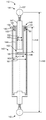
본 기술을 더 설명하기 위해, 이제 도면을 참조하여 예가 제공된다. 도 1을 참조하면, 미러 시스템(mirror system)(100)의 일례는 측면도로 개략적으로 도시되어 있다. 미러 시스템(100)은 지지 구조물(support structure)(110)을 포함할 수 있다. 미러 시스템(100)은 또한 지지 구조물(110)에 의해 지지되는 제1 미러(primary mirror)(120)를 포함할 수 있다. 게다가, 미러 시스템(100)은 지지 구조물(110)에 의해 지지되는 제2 미러(secondary mirror)(130)를 포함할 수 있다. 일부 예에서, 제1 미러(120) 및 제2 미러(130)는 광학 망원경(예를 들어, 고해상도 이미징 시스템) 및 무선 안테나에 사용될 수 있는 카세그레인 반사기(Cassegrain reflector)를 형성한다.To further illustrate the present technology, examples are now provided with reference to the drawings. Referring to FIG. 1, an example of a
지지 구조물(110)은 하나 이상의 제1 미러 스트럿(primary mirror strut)(112)에 의해 제1 미러(120)에 결합된 베이스(base)(111)(예를 들어, 미러 시스템(100)의 구조 베이스를 형성하는 벤치)를 포함할 수 있는 미터링 구조(metering structure)를 포함할 수 있다. 지지 구조물(110)은 또한 베이스(111)로부터 연장되고 제2 미러(130)에 연결된 하나 이상의 제2 미러 스트럿(secondary mirror strut)(113)을 포함할 수 있다. 예를 들어, 제2 미러 스트럿(113)은 제2 미러(130)에 결합될 수 있는 제2 미러 마운트(secondary mirror mount)(114)를 지지할 수 있다. 제1 미러 어셈블리(primary mirror assembly)(101)는 베이스(111), 제1 미러 스트럿(112) 및 제1 미러(120)를 포함할 수 있다. 제2 미러 어셈블리(secondary mirror assembly)(102)는 제2 미러 스트럿(113), 제2 미러 마운트(114) 및 제2 미러(130)를 포함할 수 있다.The
일반적인 공간 기반 애플리케이션(예를 들어, 미러 시스템이 위성에 마운트 된 애플리케이션)에서, 미러 시스템(100)은 지구의 궤도에 걸쳐 환경 변화를 겪을 수 있으며, 이는 미러 시스템(100)의 다른 부분에 대해 변할 수 있는 열 천이 조건(thermal transient condition)을 초래한다. 예를 들어, 미러 시스템(100)은 전형적으로 미러 시스템(100)의 "후단부(back end)"(103)에서 베이스(111)에 의해 위성(satellite)에 장착되며, 미러 시스템(100)의 "전단부(front end)"(104)는 위성으로부터 돌출된다. 이 구성에서, 미러 시스템(100)의 후단(103)에서의 비교적 큰 질량은 미러 시스템(100)의 전단(104)에서의 상대적으로 작은 노출된 질량에 비해 단열될 수 있다. 그러므로 전단부(104)의 구성 요소(예를 들어, 제2 미러 어셈블리(102))는 열 부하를 매일 변화시킬 수 있는 더 큰 열 변화를 경험할 수 있다(예를 들어, 주간/야간, 지구에 대한 위성의 기울기 변화(즉, 베타 궤도 각도) 등). 결과적으로, 후단부(103)의 구성 요소(예를 들어, 제1 미러 어셈블리(101))는 전단부(104)의 구성 요소(예를 들어, 제2 미러 어셈블리(102)) 만큼 열 변화가 크지 않다.In typical space-based applications (e.g., applications where the mirror system is mounted on a satellite), the
본 개시의 일 양태에서, 미러 시스템(100)의 다양한 구성 요소는 사용 중에 구성 요소에 적용되는 열 조건에 적합한 CTE를 제공하도록 선택되고 구성될 수 있다. 예를 들어, 후단부(103)의 제1 미러(120)는 0이 아닌 CTE를 가질 수 있고, 전단부(104)에서의 제2 미러(130)는 0에 가까운 CTE를 가질 수 있다. 본원에 사용된 바와 같이, "0에 가까운 CTE(near-zero CTE)" 라는 용어는 -4.1 Х 10-7 K-1 이상 및 4.1 Х 10-7 K-1 이하의 임의의 CTE를 포함한다. "0이 아닌 CTE(non-zero CTE)"라는 용어에는 이 범위를 벗어난 모든 CTE가 포함된다. 더 구체적으로, 제1 미러(120)는 실리콘 카바이드(silicon carbide)(SiC)(예를 들어, 반응 결합 또는 소결), 알루미늄, 알루미늄 실리콘 금속 매트릭스 복합재(aluminum silicon metal matrix composite), 알루미늄 실리콘 카바이드 금속 매트릭스 복합재(aluminum silicon carbide metal matrix composite), 알루미늄 베릴륨 금속 매트릭스 복합체(aluminum beryllium metal matrix composite), 베릴륨, 용융 실리카(fused silica), 붕규산 유리(borosilicate glass), 마그네슘 등과 같은 임의의 조합에서 0이 아닌 CTE를 갖는 임의의 적합한 미러 재료를 포함할 수 있다. 반면에, 제2 미러(130)는 유리-세라믹(glass-ceramic)(예를 들어, CLEARCERAM®, ZERΨTM, ZERODUR®, 리튬-알루미노실리케이트 유리-세라믹(lithium-aluminosilicate glass-ceramic)), 티타니아-실리케이트 유리(titania-silicate glass)(예를 들어, ULE®), 탄소 복합체 등과 같은 와 같은 임의의 조합에서 0에 가까운 CTE를 갖는 임의의 적합한 미러 재료를 포함할 수 있다. 따라서, 미러 시스템(100)은 상이한 CTE를 갖는 제1 및 제2 미러(120, 130)를 이용할 수 있으며, 이는 본 명세서에 기술된 바와 같이 이용될 때, 특히 미러 시스템(100)의 후단부 및 전단부(103, 104)에서의 상이한 환경 변화를 해결한다. 예를 들어, 0에 가까운 CTE 제2 미러(130)는 제2 미러(130)에서의 벌크 온도 변화(bulk temperature change)에 대한 디포커스(defocus) 감도를 감소시킬 수 있으며, 이는 제1 미러(120)에 대한 위치로 인한 온도 변화에 더 민감하다.In one aspect of the present disclosure, various components of the
일 양태에서, 지지 구조물(110)의 임의의 또는 모든 구성 요소는 거의 0에 가까운 CTE를 가질 수 있다. 예를 들어, 베이스(111), 제1 미러 스트럿(112), 제2 미러 스트럿(113) 및/또는 제2 미러 마운트(114)는 거의 0에 가까운 CTE를 가질 수 있다. 지지 구조물(110)의 구성 요소는 복합 재료(composite material)(예를 들어, 탄소 섬유, 탄소 나노 튜브와 같은 탄소 복합재료)와 같은 0에 가까운 CTE를 갖는 임의의 적합한 구조 재료를 포함할 수 있다. 예를 들어, 베이스(111), 제2 미러 스트럿(113) 및 제2 미러 마운트(114)는 탄소 섬유로 제조될 수 있다. 제2 미러 스트럿(113)과 제2 미러 마운트(114)는 INVAR® 장착 하드웨어(115)에 의해 서로 결합될 수 있다. 유사하게, 제2 미러 마운트(114)와 제2 미러(130)는 INVAR® 장착 하드웨어(mounting hardware)(116)에 의해 서로 결합될 수 있다. 구성 요소를 서로 결합할 때와 같이 일부 0이 아닌 CTE 재료가 포함될 수 있지만, 전체 또는 결합된 CTE(즉, 미터링 구조의 "체인")는 0에 가까운 CTE에 대해 지정된 범위 내에 있을 수 있다.In one aspect, any or all components of the
제2 미러 스트럿(113), 제2 미러 마운트(114) 및/또는 제2 미러(130)를 서로 열적으로 결합시키기 위해 높은 열 전도성 "열 스트랩(thermal strap)"(117)이 포함될 수 있다. 유사하게, 열 스트랩(118)은 제1 미러 스트럿(112), 제1 미러(120) 및/또는 베이스(111)를 서로 열적으로 결합시키기 위해 포함될 수 있다. 열 스트랩(117, 118)은 구성 요소를 서로 열적으로 "묶을(tie)" 수 있으며, 하나의 구성 요소에서의 온도 변화가 다른 구성 요소에 의해 신속하게 경험되어 구성 요소를 실질적으로 동일한 온도로 유지하여, 이미지 품질에 부정적인 영향을 줄 수 있는 온도 구배(temperature gradient)를 최소화할 수 있다.A high thermal conductivity “thermal strap” 117 can be included to thermally couple the
미러 시스템(100)의 전단부(104)가 위성(satellite) 상에 위치하는 곳이기 때문에, 온도를 능동적으로 제어할 수 없다. 따라서, 제2 어셈블리(102)가 온도 변화에 의해 최소의 영향을 받도록 0에 가까운 CTE를 갖는 것이 유리하다. 반면에, 미러 시스템(100)의 후단부(103)는 비교적 큰 질량을 가지며 위성에 의해 다소 절연되고, 일부 예에서는 능동적으로 온도 제어될 수 있다. 따라서, 미러 시스템(100)의 후단부(103)에 있는 구성 요소에 대해 열팽창에 대한 비교적 큰 가능성이 허용될 수 있다. 따라서, 제1 미러 어셈블리(101)는 0이 아닌 CTE를 가질 수 있다. 일부 예에서, 이는 제1 미러(120)의 메인 재료로서 0이 아닌 CTE 재료의 사용을 가능하게 하며, 이는 주로 0에 가까운 CTE 재료로 제조된 제1 미러보다 저렴하고 더 짧은 스케줄로 제조될 수 있다.Since the
제1 미러 스트럿(112)은 임의의 적합한 구조를 가질 수 있고 본원에 기술된 바와 같이 본 발명에 따라 임의의 적합한 재료로 제조될 수 있다. 일부 예에서, 제1 미러 스트럿(112)은 0이 아닌 CTE 제1 미러(120)에 열 보상을 제공하도록 구성될 수 있는 음의 CTE를 포함할 수 있다. 이 구성은 제2 미러의 0에 가까운 CTE와 다양한 지지 구성 요소의 일정한 공액 위치를 일치시키기 위해 활용될 수 있다. 이하, 도 3a 및 도 3b를 참조하여 보다 상세하게 설명한다. 다시 말해서, 제1 미러 스트럿(112)에 대해 적절한 음의 CTE를 선택함으로써, 미러 시스템(100)의 후단부(103)(즉, 제1 미러 단부) 및 전단부(104)(즉, 제2 미러 단부)의 거동은 주어진 환경에 대해 매칭 될 수 있고, 각 끝점의 포커스 포인트는 온도에 따라 일정하게 유지된다.The
도 2에 도시된 바와 같이, 음의 CTE 스트럿(112)은 본체부(140) 및 본체부(140)에 대해 서로 대 향하여 배치된 제1 및 제2 결합부(141, 142)를 포함할 수 있다. 결합부(141, 142)는 각각 외부 구조(예를 들어, 제1 미러(120) 및 도 1의 베이스(111)에 결합을 용이하게 하도록 구성된 피팅 또는 하드웨어)와 인터페이스하고 스트럿 길이(143)를 정의하도록 구성될 수 있다. 일 양태에서, 결합부(141, 142)는 스트럿(112)과 외부 구조물의 상대 회전을 용이하게 하기 위해 외부 구조물과 인터페이스하기 위한 구형 볼을 포함할 수 있다. 일 양태에서, 결합부(141, 142)는 조립시 제1 미러(120)의 적절한 정렬을 용이하게 하기 위해 스트럿(112)(예를 들어, 나사산 로드(threaded rod)를 통한)의 길이 조절을 용이하게 하도록 구성될 수 있다.As shown in FIG. 2, the
음의 CTE 스트럿(112)은 또한 본체부(140)에 결합된 제1 단부(145)를 갖는 오프셋 연장 부재 또는 스페이서(144)를 포함할 수 있고, 중간 연장 부재(147)에 의해 제1 결합부(141)에 결합된 제2 단부(146)를 포함한다. 제1 단부(145)는 제1 결합부(141)와 제2 단부(146) 사이에 있을 수 있다. 제1 및 제2 단부(145, 146)는 스트럿 길이(143)에 평행한 오프셋 길이(148)를 정의할 수 있다. 음의 CTE 스트럿(112)이 온도가 상승하면, 오프셋 길이(148)는 스트럿 길이(143)를 감소시키기에 충분한 오프셋 연장 부재(144)의 열 팽창으로 인해 증가하도록 구성될 수 있다.
본체부(140), 결합부(141, 142) 및 중간 연장 부재(147)는 임의의 적절한 CTE를 가질 수 있다. 일부 예에서, 본체부(140), 결합부(141), 결합부(142) 및/또는 중간 연장 부재(147)는 0에 가까운 CTE를 가질 수 있다. 따라서, 본체부(140), 결합부(141), 결합부(142) 및/또는 중간 연장 부재(147)는 복합 재료(예를 들어, 탄소 섬유, 탄소 나노 튜브 등)와 같은 거의 0에 가까운 CTE를 갖는 임의의 적합한 구조 재료를 포함할 수 있다. 니켈-철 합금(nickel-iron alloy)(예를 들어, INVAR®과 같은 64FeNi)과 같은 0이 아닌 CTE 재료는 전체 또는 결합된 CTE(즉, 구조의 "사슬")가 내부에 있도록 선택적으로 사용될 수 있다. 0에 가까운 CTE에 대해 지정된 범위로, 주어진 구조 또는 구조의 조합에 대해 0에 가까운 CTE를 제공한다. 일부 예에서, 본체부(140), 결합부(141), 결합부(142) 및/또는 중간 연장 부재(147)는 질소 강화 스테인레스 스틸(예를 들어, NITRONIC®)과 같은 0이 아닌 CTE를 갖는 재료를 포함할 수 있다. 일부 예에서, 본체부(140), 결합부(141), 결합부(142) 및/또는 중간 연장 부재(147)는 0이 아닌 양의 CTE를 가질 수 있다. 오프셋 연장 부재(144)는 임의의 적합한 0이 아닌 양의 CTE(즉, 0에 가까운 CTE보다 큰 CTE)를 가질 수 있다. 따라서, 오프셋 연장 부재(144)는 알루미늄, 티타늄, 철, 강철, 니켈, 베릴륨 등과 같은 0이 아닌 양의 CTE를 갖는 임의의 적합한 구조 재료를 포함할 수 있다.The
일부 구체 예에서, 음의 CTE 스트럿(112)은 본체부(140)과 오프셋 연장 부재(144)의 제1 단부(145)를 연결하는 인서트(149)를 포함할 수 있다. 인서트(149)는 2 개의 상이한 CTE 재료 사이에 구조적 버퍼를 제공함으로써 0이 아닌 양의 CTE 오프셋 연장 부재(144)를 0에 가까운 CTE 본체부(140)에 결합하는 것을 도울 수 있다. 일부 예에서, 인서트(149)는 니켈-철 합금(예를 들어, 64FeNi, 예컨대 INVAR®)과 같은 재료를 포함할 수 있고, 이는 오프셋 연장 부재(144)의 재료(예를 들어, 알루미늄)보다 강하고, 본체부(140)의 파손을 방지하기 위해 본체부(140)(예를 들어, 복합 재료)과 유사한 CTE를 갖는다.In some embodiments, the
본체부(140), 인서트(insert)(149), 오프셋 연장 부재(144) 및 중간 연장 부재(147)는 접착제, 나사산 인터페이스 표면(예를 들어, 나사산 표면 또는 연결된 구성 요소 사이의 일부를 결합하는), 리벳, 용접 등을 이용하는 것과 같은 임의의 적절한 방식으로 결합될 수 있다. 일례로, 인서트(149)는 150에서 본체부(140)에 접합될 수 있고, 오프셋 연장 부재(144)의 제1 단부(145)는 151에서 나사산 인터페이스 표면을 갖는 인서트(149)에 결합될 수 있고, 중간 연장 부재(147)는 나사산 인터페이스 표면을 갖는 152에서 오프셋 연장 부재(144)의 제2 단부(146)에 결합될 수 있다. 각각의 본체부(140), 인서트(149) 및 오프셋 연장 부재(144)의 플랜지(Flange)(153-155)는 구성 요소의 결합을 용이하게 하고 오프셋 연장 부재(144)의 제1 단부(145)에서 구성 요소의 적절한 상대 위치 설정을 제공할 수 있다. 오프셋 연장 부재(144)의 제2 단부(146)에서, 중간 연장 부재(147)는 오프셋 연장 부재(144)의 바닥면(156)과 완전히 접촉하도록 배치될 수 있다. 오프셋 연장 부재(144)의 플랜지(155) 및 바닥면(156)은 오프셋 길이(148)를 설정할 수 있다.
본체부(140), 오프셋 연장 부재(144) 및/또는 중간 연장 부재(147)는 각각 원통형 구성을 포함할 수 있다. 일부 예에서, 본체부(140), 오프셋 연장 부재(144) 및/또는 중간 연장 부재(147)는 종축(longitudinal axis)(157)을 따라 동축으로 정렬될 수 있다. 따라서, 본체부(140), 오프셋 연장 부재(144) 및/또는 중간 연장 부재(147)는 서로 일직선이 될 수 있다. 오프셋 연장 부재(144)는 본체부(140) 내에 적어도 부분적으로 끼워지도록 구성될 수 있고, 중간 연장 부재(147)는 오프셋 연장 부재(144) 내에 끼워지도록 구성될 수 있다. 따라서, 오프셋 연장 부재(144)의 외경(outer diameter)(160)은 본체부(140)의 내경(inner diameter)(161)보다 작을 수 있고, 중간 연장 부재(147)의 외경(162)은 오프셋 연장 부재(144)의 내경(163)보다 작을 수 있다. 이는 과도한 내부 응력을 발생시키지 않으면서 열 팽창/수축으로 인해 이들 구성 요소가 서로에 대해 자유롭게 이동하는 것을 가능하게 하지만, 오프셋 길이(148) 및 스트럿 길이(143)는 온도에 따라 변한다. 본 명세서에 기술된 바와 같이, 열 스트랩(thermal strap)(도 1의 118)은 제1 미러(120)와 오프셋 연장 부재(144)의 온도를 밀접하게 연결하여 제1 미러(120)와 오프셋 연장 부재(144)를 적절한 동작 및 열 보상을 위해 동일한 온도로 유지하는데 이용될 수 있다.The
스트럿(112)의 다양한 구성 요소 각각의 CTE 및 축 방향 확장 길이는 0이 아닌 CTE 제1 미러(120)에 대한 수동적 열 보상을 제공하기 위해 주어진 동작 온도 범위에 대해 튜닝 된 스트럿(112)의 원하는 복합 CTE를 제공하도록 구성될 수 있다. 본체부(140), 결합부(141), 결합부(142) 및 중간 연장 부재(147)가 주로 0에 가까운 CTE 재료로 구성되는 예에서, 오프셋 연장 부재(144)의 오프셋 길이(148)는 스트럿(112)의 CTE를 설정하는데 있어서 주요 변수이다.The desired CTE and axial extension length of each of the various components of the
동작시, 오프셋 연장 부재(144)의 온도가 증가함에 따라, 오프셋 연장 부재(144)는 오프셋 길이(148)를 확장 및 증가시킨다. 중간 연장 부재(147)가 오프셋 연장 부재(144)의 제2 단부(146)에 연결되어 있기 때문에, 결합부(141)는 대향 결합부(142)를 향하여 이동하여 스트럿 길이(143)를 효과적으로 수축 또는 단축수축시킨다. 온도가 감소하면 반대의 현상이 발생한다. 결과는 스트럿(112)에 대한 순 음의 CTE이며, 이는 온도가 증가함에 따라 스트럿 길이(143)가 감소하고 온도가 감소함에 따라 스트럿 길이(143)가 증가한다.In operation, as the temperature of the offset extending
일 양태에서, 도 1 및 2에 개략적으로 도시된 바와 같이 3a와 3b, 음의 CTE 스트럿(112)은 주어진 양의 CTE 제1 미러(120)의 팽창/수축을 상쇄하는 주어진 온도 범위에 걸쳐 적절한 수축/팽창을 제공하기 위해 음의 CTE를 갖도록 구성될 수 있다. 일반적으로, 도 3a에 도시된 바와 같은 양의 CTE 제1 미러(120)의 경우, 제1 미러(120)가 감소된 온도로 수축함에 따라, 제1 미러(120)의 포커스 포인트(105)는 제2 미러(미도시) 앞에서 제1 미러를 향해 시프트 하는 경향이 있다. 한편, 도 3b에 도시된 바와 같이, 제1 미러(120)가 온도가 증가함에 따라 팽창함에 따라, 포커스 포인트(105)는 제2 미러(도시되지 않음) 뒤에 제1 미러(120)로부터 멀어지도록 시프트 하는 경향이 있다. 포커스 포인트(105)가 온도 변화에 따라 시프트 하는 경향은 포커스를 유지하는 것을 어렵게 할 수 있다.In one aspect, as schematically shown in FIGS. 1 and 2, 3a and 3b, negative CTE struts 112 are suitable over a given temperature range that offsets the expansion/contraction of a given amount of CTE
그러나, 양의 CTE 제1 미러(120)와 함께 음의 CTE 스트럿(112)을 이용하면, 주어진 온도 범위에 걸쳐 제2 미러에 대해 실질적으로 동일한 위치에 제1 미러(120)의 포커스 포인트(105)를 수동적으로 유지할 수 있다. 예를 들어, 제1 미러(120)가 온도가 감소함에 따라 수축하고 포커스 포인트(105)를 제1 미러(120) 쪽으로 시프트 시키면, 음의 CTE 스트럿(112)은 상응하게 확장 또는 연장되고 제1 미러(120)를 제2 미러를 향해 밀어 제2 미러에 대해 실질적으로 동일한 위치에 포커스 포인트(105)를 수동적으로 유지한다. 제1 미러(120)가 온도가 증가함에 따라 팽창하고 포커스 포인트(105)를 제1 미러(120)로부터 멀어지면서, 음의 CTE 스트럿(112)은 제2 미러에 대해 실질적으로 동일한 위치에 포커스 포인트(105)를 수동적으로 유지하기 위해 제1 미러(120)를 제2 미러로부터 상응하게 수축 또는 단축 및 끌어당긴다. 따라서, 음의 CTE 스트럿(112)은 다양한 온도 구배(temperature gradient)를 수용하고 제1 미러 디포커스 감도를 감소시키도록 튜닝 되거나 구성될 수 있다. 다시 말해, 음의 CTE 스트럿(112)에 의해 제공되는 수동 열 보상은 열 변화에 효과적으로 둔감 한 미러 시스템을 제공할 수 있다. 그 결과 광범위한 온도 범위에서 제1 미러 포커스를 유지할 수 있는 미러 시스템이 탄생했다. 게다가, 음의 CTE 스트럿(112)은 활성 열 제어의 필요성을 제거하거나 최소화하면서 저렴한 비용으로 비교적 저렴한 높은 CTE 제1 미러를 사용할 수 있게 한다.However, using the
일부 예에서, 음의 CTE 스트럿은 미러 시스템의 동작 환경에 따라 또는 제1 미러(즉, 미러 시스템의 후단부)가 활성 온도 제어와 같은 주어진 온도로 유지될 수 있는 지에 따라 이용되지 않을 수 있다.In some examples, the negative CTE strut may not be used depending on the operating environment of the mirror system or whether the first mirror (ie, the rear end of the mirror system) can be maintained at a given temperature, such as active temperature control.
본 명세서에 개시된 원리는 미러 시스템(100)이 온도 변화를 경험하는 동안 이미지 품질을 허용 가능한 레벨로 유지할 수 있다. 예를 들어, 도 4는 구성 요소 온도 및 이미지 품질(파면 오류(wavefront error)로 정량화 됨)을 그래픽으로 나타낸다. 노출된 전단부 구성 요소(예를 들어, 제2 미러 및 스트럿)의 온도는 환경 조건의 변화에 따라 크게 달라질 수 있다. 비교적 방대한 절연 후단면 구성 요소(예를 들어, 제1 미러)의 온도는 비교적 일정하게 유지된다. 후단면 구성 요소는 일반적으로 더 긴 시간에 걸쳐 온도 변화를 보게 된다. 그래프에서 볼 수 있듯이 파면 오류(예를 들어, 이미지 품질)는 허용 가능한 수준으로 유지되는 반면 전단부 및 후단부 구성 요소는 서로 다른 유형의 온도 변화 특성을 경험한다. 따라서, 미러 시스템(100)은 동작 환경에 특정한 재료 선택의 이점을 얻을 수 있으므로, 미러 시스템은 필요할 때(즉, 거의 0에 가까운 CTE 미러 및 구조적 구성 요소를 이용하여 노출된 전단부에서) 열에 둔감하고, 및 허용 가능한 곳에서 약간의 열 감도를 허용한다(즉, 0이 아닌 CTE 미러 및 선택적으로 음의 CTE 스트럿을 사용하는 비교적 방대한 절연 후단부에서). 미러 시스템(100)에서 재료(즉, CTE 특성)의 이러한 전략적 사용은 특히 제조하기 가장 어렵고 비싼 구성 요소인 제1 미러와 관련하여 제조 시간 및 비용을 절약할 수 있다. 결과적으로, 미러 시스템(100)의 이미지 품질은 거의 0에 가까운 CTE 재료로 제조된 망원경의 품질과 비교될 수 있지만, 훨씬 더 짧은 시간 프레임에서 제조하면서 훨씬 비싸지 않다. 게다가, 미러 시스템(100)의 비용 및 제조 시간은 우수한 이미지 품질을 생성하면서 완전히 동일한 높은 CTE 재료(예를 들어, SiC)로 제조된 망원경의 비용 및 시간에 근접할 수 있다. 따라서, 본 명세서에 개시된 미러 시스템(100)은 다른 이미징 시스템에 비해 감소된 비용으로 낮은 파면 에러를 갖는 높은 공간 해상도 이미징을 생성할 수 있다.The principles disclosed herein can maintain image quality at an acceptable level while the
도면에 예시된 예를 참조하였고, 이를 설명하기 위해 특정 용어가 사용되었다. 그럼에도 불구하고 기술의 범위의 제한이 의도되지 않는다는 것이 이해될 것이다. 본 명세서에 예시된 특징 및 본 명세서에 예시된 바와 같은 예의 추가 적용의 변경 및 추가 수정은 본 설명의 범위 내에서 고려되어야 한다.Reference has been made to the example illustrated in the drawings, and specific terms have been used to describe it. It will nevertheless be understood that no limitation of the scope of the technology is intended. Changes and further modifications of the features illustrated herein and further application of examples as illustrated herein should be considered within the scope of this description.
본 명세서는 본 명세서에 기술된 일부 실시예 또는 특징이 본 명세서에 기술된 다른 실시예 또는 특징과 결합될 수 있음을 명백하게 개시하지 않을 수 있지만, 본 개시는 당업자가 실시할 수 있는 임의의 이러한 조합을 설명하기 위한 것으로 읽혀 져야한다. 본 명세서에서 "또는" 의 사용자는 본 명세서에서 달리 지시되지 않는 한 비배타적, 즉 "및/또는"을 의미하는 것으로 이해되어야 한다.While this specification may not explicitly disclose that some embodiments or features described herein can be combined with other embodiments or features described herein, the present disclosure is any such combination that can be practiced by those skilled in the art. It should be read as an explanation. It should be understood that a user of “or” herein refers to non-exclusive, ie, “and/or” unless indicated otherwise herein.
또한, 설명된 특징, 구조 또는 특성은 하나 이상의 예에서 임의의 적절한 방식으로 결합될 수 있다. 전술한 설명에서, 기술된 기술의 예를 완전히 이해하기 위해 다양한 구성의 예와 같은 다수의 특정 세부 사항이 제공되었다. 그러나, 기술은 하나 이상의 특정 세부 사항 없이 또는 다른 방법, 구성 요소, 장치 등으로 실시될 수 있음을 인식할 것이다. 다른 경우에, 공지된 구조 또는 동작은 기술의 양태를 모호하게 하는 것을 피하기 위해 상세하게 도시되거나 설명되지 않는다.Also, the described features, structures, or characteristics can be combined in any suitable way in one or more examples. In the foregoing description, numerous specific details have been provided, such as examples of various configurations, in order to fully understand the examples of the described techniques. However, it will be appreciated that the technique may be practiced without one or more specific details or in other ways, components, devices, or the like. In other instances, well-known structures or operations are not shown or described in detail in order to avoid obscuring aspects of the technology.
주제는 구조적 특징 및/또는 동작에 특정한 용어로 설명되었지만, 첨부된 청구 범위에 정의된 주제는 반드시 전술한 특정 특징 및 동작으로 제한되는 것은 아니라는 것을 이해해야 한다. 오히려, 전술한 특정 특징 및 동작은 청구항을 구현하는 예시적인 형태로서 개시된다. 기술된 기술의 사상 및 범위를 벗어나지 않으면서 다수의 수정 및 대안적인 구성이 고안될 수 있다.While the subject matter has been described in terms specific to structural features and/or actions, it should be understood that the subject matter defined in the appended claims is not necessarily limited to the specific features and actions described above. Rather, the specific features and acts described above are disclosed as example forms of implementing the claims. A number of modifications and alternative configurations can be devised without departing from the spirit and scope of the described technology.
Claims (34)
제1 미러; 및
상기 제1 미러에 대해 지지되는 제2 미러를 포함하고,
상기 제1 미러 및 상기 제2 미러는 상이한 열팽창 계수(CTE)를 갖는
장치.
In the mirror system,
A first mirror; And
And a second mirror supported with respect to the first mirror,
The first mirror and the second mirror have different coefficients of thermal expansion (CTE)
Device.
상기 제1 미러는 0이 아닌 CTE를 갖고,
상기 제2 미러는 0에 가까운 CTE를 갖는
장치.
According to claim 1,
The first mirror has a non-zero CTE,
The second mirror has a CTE close to zero
Device.
상기 지지 구조물은 상기 제1 미러에 결합된 베이스
를 포함하는
장치.
According to claim 1,
The support structure is a base coupled to the first mirror
Containing
Device.
상기 베이스와 상기 제1 미러를 결합하는 스트럿
을 더 포함하는
장치.
According to claim 3,
Strut coupling the base and the first mirror
Containing more
Device.
상기 스트럿은 음의 CTE를 갖는
장치.
The method according to any one of claims 1 to 4,
The strut has a negative CTE
Device.
상기 제1 미러와 상기 스트럿을 열적으로 결합시키는 열 스트랩
을 더 포함하는
장치.
The method of claim 5,
Thermal strap for thermally coupling the first mirror and the strut
Containing more
Device.
상기 지지 구조물은 상기 베이스로부터 연장되고 상기 제2 미러에 결합된 스트럿
을 포함하는
장치.
According to claim 1,
The support structure is a strut extending from the base and coupled to the second mirror
Containing
Device.
상기 지지 구조물은 복합 재료, 니켈-철 합금 또는 이들의 조합
을 포함하는
장치.
According to claim 1,
The support structure is a composite material, a nickel-iron alloy, or a combination thereof
Containing
Device.
상기 복합 재료는 탄소 섬유
를 포함하는
장치.
The method of claim 8,
The composite material is carbon fiber
Containing
Device.
상기 니켈-철 합금은 64FeNi
를 포함하는
장치.
The method of claim 8,
The nickel-iron alloy is 64FeNi
Containing
Device.
상기 지지 구조물은 0에 가까운 CTE를 갖는
장치.
According to claim 1,
The support structure has a CTE close to zero
Device.
상기 제1 미러는 SiC, 알루미늄 또는 이들의 조합
을 포함하는
장치.
According to claim 1,
The first mirror is SiC, aluminum or a combination thereof
Containing
Device.
상기 제2 미러는 리튬-알루미노실리케이트 유리-세라믹 재료, 붕규산 유리 재료 또는 이들의 조합
을 포함하는
장치.
According to claim 1,
The second mirror is a lithium-aluminosilicate glass-ceramic material, a borosilicate glass material, or a combination thereof
Containing
Device.
상기 제1 미러 및 상기 제2 미러는 카세그레인 반사기를 형성하는
장치.
According to claim 1,
The first mirror and the second mirror form a case grain reflector
Device.
베이스, 및 상기 베이스로부터 연장되는 제2 미러 스트럿을 갖는 지지 구조물;
제1 미러 스트럿에 의해 상기 베이스에 결합되고 0이 아닌 열팽창 계수(CTE)를 갖는 제1 미러; 및
상기 제2 미러 스트럿에 결합되고 거의 0의 CTE를 갖는 제2 미러
를 포함하는
장치.
In the mirror system,
A support structure having a base and a second mirror strut extending from the base;
A first mirror coupled to the base by a first mirror strut and having a non-zero coefficient of thermal expansion (CTE); And
A second mirror coupled to the second mirror strut and having a CTE of almost zero
Containing
Device.
상기 제1 미러 스트럿은 음의 CTE를 갖는
장치.
The method of claim 15,
The first mirror strut has a negative CTE
Device.
상기 제제1 미러와 상기 제제1 미러 스트럿을 열적으로 결합시키는 열 스트랩
을 더 포함하는
장치.
The method of claim 16,
A thermal strap for thermally coupling the formulation 1 mirror and the formulation 1 mirror strut
Containing more
Device.
상기 지지 구조물은 복합 재료, 니켈-철 합금 또는 이들의 조합
을 포함하는
장치.
The method of claim 15,
The support structure is a composite material, a nickel-iron alloy, or a combination thereof
Containing
Device.
상기 복합 재료는 탄소 섬유
를 포함하는
장치.
The method of claim 18,
The composite material is carbon fiber
Containing
Device.
상기 니켈-철 합금은 64FeNi
를 포함하는
장치.
The method of claim 18,
The nickel-iron alloy is 64FeNi
Containing
Device.
상기 지지 구조물은 거의 0에 가까운 CTE를 갖는
장치.
The method of claim 15,
The support structure has a CTE near 0
Device.
상기 제1 미러는 SiC, 알루미늄 또는 이들의 조합
을 포함하는
장치.
The method of claim 15,
The first mirror is SiC, aluminum or a combination thereof
Containing
Device.
상기 제2 미러는 리튬-알루미노실리케이트 유리-세라믹 재료, 붕규산 유리 재료 또는 이들의 조합
을 포함하는
장치.
The method of claim 15,
The second mirror is a lithium-aluminosilicate glass-ceramic material, a borosilicate glass material, or a combination thereof
Containing
Device.
상기 제1 미러 및 제2 미러는 카세그레인 반사기를 형성하는
장치.
The method of claim 15,
The first mirror and the second mirror form a case grain reflector
Device.
본체부;
상기 본체부 주위에서 서로 대향하여 배치되고 스트럿 길이를 정의하는 제1 결합부 및 제2 결합부 - 상기 제1 및 제2 결합부는 각각 외부 구조와 인터페이스 하도록 구성된 -; 및
상기 본체부에 결합된 제1 단부 및 중간 연장 부재에 의해 상기 제1 결합부에 결합된 제2 단부를 갖는 오프셋 연장 부재 - 상기 제1 단부는 상기 제1 결합부와 상기 제2 단부 사이에 있고, 상기 제1 및 제2 단부는 상기 스트럿 길이와 평행한 오프셋 길이를 정의하는 -;
을 포함하고,
상기 음의 CTE 스트럿이 온도가 증가할 때, 상기 오프셋 길이는 스트럿 길이를 감소시키기에 충분한 오프셋 연장 부재의 열 팽창으로 인해 증가하도록 구성되는
장치.
For negative thermal expansion coefficient (CTE) struts,
Body part;
A first coupling portion and a second coupling portion disposed opposite each other around the body portion and defining a strut length, wherein the first and second coupling portions are each configured to interface with an external structure; And
An offset extension member having a first end coupled to the body portion and a second end coupled to the first engagement portion by an intermediate extension member, the first end being between the first engagement portion and the second end , Wherein the first and second ends define an offset length parallel to the strut length;
Including,
When the temperature of the negative CTE strut increases, the offset length is configured to increase due to thermal expansion of the offset extension member sufficient to reduce the strut length.
Device.
상기 오프셋 연장 부재는 알루미늄
을 포함하는
장치.
The method of claim 25,
The offset extension member is aluminum
Containing
Device.
상기 본체부, 상기 중간 연장 부재, 또는 둘 모두는 0에 가까운 CTE를 갖는
장치.
The method of claim 25,
The body portion, the intermediate extension member, or both have a CTE close to zero
Device.
상기 본체부, 상기 중간 연장 부재, 또는 둘 모두는 복합 재료, 니켈-철 합금 또는 이들의 조합
을 포함하는
장치.
The method of claim 25,
The body portion, the intermediate extension member, or both are composite materials, a nickel-iron alloy, or combinations thereof
Containing
Device.
상기 복합 재료는 탄소 섬유
를 포함하는
장치.
The method of claim 28,
The composite material is carbon fiber
Containing
Device.
상기 니켈-철 합금은 64FeNi
를 포함하는
장치.
The method of claim 28,
The nickel-iron alloy is 64FeNi
Containing
Device.
상기 본체부, 상기 오프셋 연장 부재 및 상기 중간 연장 부재 중 적어도 하나는 원통형 구성
을 포함하는
장치.
The method of claim 25,
At least one of the main body portion, the offset extension member and the intermediate extension member has a cylindrical configuration
Containing
Device.
상기 본체부와 상기 오프셋 연장 부재의 상기 제1 단부를 연결하는 인서트
를 더 포함하는
장치.
The method of claim 25,
An insert connecting the body portion and the first end of the offset extension member
Containing more
Device.
상기 인서트는 니켈-철 합금
을 포함하는
장치.
The method of claim 32,
The insert is a nickel-iron alloy
Containing
Device.
상기 니켈-철 합금은 64FeNi
를 포함하는
장치.The method of claim 33,
The nickel-iron alloy is 64FeNi
Containing
Device.
Priority Applications (1)
| Application Number | Priority Date | Filing Date | Title |
|---|---|---|---|
| KR1020227004186A KR102479668B1 (en) | 2017-11-30 | 2018-09-28 | Multi-material mirror system |
Applications Claiming Priority (3)
| Application Number | Priority Date | Filing Date | Title |
|---|---|---|---|
| US15/828,223 | 2017-11-30 | ||
| US15/828,223 US10877237B2 (en) | 2017-11-30 | 2017-11-30 | Multi-material mirror system |
| PCT/US2018/053600 WO2019108300A1 (en) | 2017-11-30 | 2018-09-28 | Multi-material mirror system |
Related Child Applications (1)
| Application Number | Title | Priority Date | Filing Date |
|---|---|---|---|
| KR1020227004186A Division KR102479668B1 (en) | 2017-11-30 | 2018-09-28 | Multi-material mirror system |
Publications (2)
| Publication Number | Publication Date |
|---|---|
| KR20200078582A true KR20200078582A (en) | 2020-07-01 |
| KR102469991B1 KR102469991B1 (en) | 2022-11-22 |
Family
ID=63963478
Family Applications (2)
| Application Number | Title | Priority Date | Filing Date |
|---|---|---|---|
| KR1020207015050A KR102469991B1 (en) | 2017-11-30 | 2018-09-28 | Multi-material mirror system |
| KR1020227004186A KR102479668B1 (en) | 2017-11-30 | 2018-09-28 | Multi-material mirror system |
Family Applications After (1)
| Application Number | Title | Priority Date | Filing Date |
|---|---|---|---|
| KR1020227004186A KR102479668B1 (en) | 2017-11-30 | 2018-09-28 | Multi-material mirror system |
Country Status (7)
| Country | Link |
|---|---|
| US (2) | US10877237B2 (en) |
| EP (1) | EP3717950A1 (en) |
| JP (1) | JP6982181B2 (en) |
| KR (2) | KR102469991B1 (en) |
| CA (1) | CA3081549A1 (en) |
| IL (1) | IL274495B (en) |
| WO (1) | WO2019108300A1 (en) |
Families Citing this family (3)
| Publication number | Priority date | Publication date | Assignee | Title |
|---|---|---|---|---|
| US10877237B2 (en) | 2017-11-30 | 2020-12-29 | Raytheon Company | Multi-material mirror system |
| US11327208B2 (en) * | 2018-05-30 | 2022-05-10 | Raytheon Company | Method of manufacture for a lightweight, high-precision silicon carbide mirror assembly |
| FR3137977A1 (en) * | 2022-07-13 | 2024-01-19 | Bertin Winlight | Imaging system |
Citations (2)
| Publication number | Priority date | Publication date | Assignee | Title |
|---|---|---|---|---|
| JP2010262163A (en) * | 2009-05-08 | 2010-11-18 | Nikon Corp | Variable power type telephotographic optical system and optical device including the same |
| KR101688426B1 (en) * | 2016-06-24 | 2017-01-02 | 한화시스템 주식회사 | A optics assembliy |
Family Cites Families (29)
| Publication number | Priority date | Publication date | Assignee | Title |
|---|---|---|---|---|
| US3914063A (en) * | 1973-05-24 | 1975-10-21 | Unistrut Corp | Space frame connecting fixture |
| US4285728A (en) | 1975-02-06 | 1981-08-25 | Owens-Illinois, Inc. | Method of making low expansion crystallized glass-ceramics and telescope mirror blanks made thereby |
| US4856887A (en) | 1987-04-01 | 1989-08-15 | Hughes Aircraft Company | Lightweight silicon carbide mirror |
| US5071596A (en) | 1989-10-23 | 1991-12-10 | Cvd Incorporated | Fabrication of lightweight ceramic mirrors by means of a chemical vapor deposition process |
| US5076700A (en) | 1990-12-20 | 1991-12-31 | Litton Systems, Inc. | Bonded lightweight mirror structure |
| US5565052A (en) | 1992-03-05 | 1996-10-15 | Industrieanlagen-Betriebsgesellschaft Gmbh | Method for the production of a reflector |
| US5296311A (en) | 1992-03-17 | 1994-03-22 | The Carborundum Company | Silicon carbide reinforced reaction bonded silicon carbide composite |
| US5302561A (en) | 1993-03-11 | 1994-04-12 | Cercom, Inc. | Monolithic, fully dense silicon carbide mirror and method of manufacturing |
| US5741445A (en) | 1996-02-06 | 1998-04-21 | Cvd, Incorporated | Method of making lightweight closed-back mirror |
| US7244034B1 (en) | 1999-08-20 | 2007-07-17 | M Cubed Technologies, Inc. | Low CTE metal-ceramic composite articles, and methods for making same |
| US6176588B1 (en) | 1999-12-14 | 2001-01-23 | Corning Incorporated | Low cost light weight mirror blank |
| DE10125554C2 (en) | 2001-05-23 | 2003-06-18 | Astrium Gmbh | Ultra-light and ultra-rigid all-ceramic reflector and method for producing and using such a reflector |
| GB0119033D0 (en) | 2001-08-03 | 2001-09-26 | Southampton Photonics Ltd | An optical fibre thermal compensation device |
| US20050141108A1 (en) * | 2001-09-06 | 2005-06-30 | Atkinson Charles B. | Cryogenic telescope using hybrid material for thermal stability |
| JP4068496B2 (en) | 2003-04-14 | 2008-03-26 | Nec東芝スペースシステム株式会社 | Mirror surface base material, mirror body using the same, and optical device using the mirror body |
| US20070207268A1 (en) | 2003-12-08 | 2007-09-06 | Webb R K | Ribbed CVC structures and methods of producing |
| US7195361B2 (en) | 2005-01-19 | 2007-03-27 | Xinetics, Inc. | Active hybrid optical component |
| CN101470223B (en) | 2007-12-26 | 2012-10-03 | 中国科学院大连化学物理研究所 | Method for fabricating RB-SiC ultra-smooth surface reflection mirror through surface modification technology |
| JP2009276378A (en) | 2008-05-12 | 2009-11-26 | Mitsubishi Electric Corp | Lightweight mirror and method of manufacturing the same |
| DE102008039042B4 (en) | 2008-08-21 | 2011-04-14 | Schott Ag | Substrate for a mirror carrier with reduced weight and mirror with weight-reduced mirror carrier |
| JP2010152090A (en) * | 2008-12-25 | 2010-07-08 | Mitsubishi Electric Corp | Reflecting mirror system |
| DE102009011863B4 (en) | 2009-03-05 | 2024-02-08 | Asml Netherlands B.V. | Lightweight support structure, especially for optical components, method for their production and use of the support structure |
| US8292537B2 (en) | 2009-06-16 | 2012-10-23 | Utah State University Research Foundation | Thermal expansion compensation method and system |
| US20110221084A1 (en) | 2010-03-10 | 2011-09-15 | Trex Enerprises Corp. | Honeycomb composite silicon carbide mirrors and structures |
| US8607513B2 (en) | 2011-12-30 | 2013-12-17 | Panelclaw, Inc. | Thermal growth compensators, systems, and methods |
| US9958638B2 (en) | 2013-09-13 | 2018-05-01 | Raytheon Company | Optimal kinematic mount for large mirrors |
| CN104451580A (en) | 2014-12-29 | 2015-03-25 | 中国科学院长春光学精密机械与物理研究所 | Preparation method of RB-SiC (Reaction Bonded Silicon Carbide) substrate reflector surface modification layer |
| US9823459B2 (en) | 2015-09-29 | 2017-11-21 | Raytheon Company | High-stiffness structure for larger aperture telescope |
| US10877237B2 (en) | 2017-11-30 | 2020-12-29 | Raytheon Company | Multi-material mirror system |
-
2017
- 2017-11-30 US US15/828,223 patent/US10877237B2/en active Active
-
2018
- 2018-09-28 KR KR1020207015050A patent/KR102469991B1/en active IP Right Grant
- 2018-09-28 KR KR1020227004186A patent/KR102479668B1/en active IP Right Grant
- 2018-09-28 CA CA3081549A patent/CA3081549A1/en active Pending
- 2018-09-28 JP JP2020528955A patent/JP6982181B2/en active Active
- 2018-09-28 EP EP18792683.7A patent/EP3717950A1/en active Pending
- 2018-09-28 WO PCT/US2018/053600 patent/WO2019108300A1/en unknown
-
2020
- 2020-01-03 US US16/734,144 patent/US11314041B2/en active Active
- 2020-05-06 IL IL274495A patent/IL274495B/en unknown
Patent Citations (2)
| Publication number | Priority date | Publication date | Assignee | Title |
|---|---|---|---|---|
| JP2010262163A (en) * | 2009-05-08 | 2010-11-18 | Nikon Corp | Variable power type telephotographic optical system and optical device including the same |
| KR101688426B1 (en) * | 2016-06-24 | 2017-01-02 | 한화시스템 주식회사 | A optics assembliy |
Non-Patent Citations (2)
| Title |
|---|
| Picometer resolution interferometric characterization of the dimensional stability of zero CTE CFRP* * |
| Wavefront control of the Large Optics Test and Integration Site (LOTIS) 6.5m Collimator* * |
Also Published As
| Publication number | Publication date |
|---|---|
| US10877237B2 (en) | 2020-12-29 |
| US20200142154A1 (en) | 2020-05-07 |
| US11314041B2 (en) | 2022-04-26 |
| KR20220025149A (en) | 2022-03-03 |
| IL274495A (en) | 2020-06-30 |
| WO2019108300A1 (en) | 2019-06-06 |
| KR102469991B1 (en) | 2022-11-22 |
| IL274495B (en) | 2021-09-30 |
| JP6982181B2 (en) | 2021-12-17 |
| EP3717950A1 (en) | 2020-10-07 |
| US20190162931A1 (en) | 2019-05-30 |
| KR102479668B1 (en) | 2022-12-20 |
| JP2021504755A (en) | 2021-02-15 |
| CA3081549A1 (en) | 2019-06-06 |
Similar Documents
| Publication | Publication Date | Title |
|---|---|---|
| US11314041B2 (en) | Multi-material mirror system | |
| JP6214773B2 (en) | Optimal kinematic mount for large mirrors | |
| US6402329B1 (en) | Assembly for mounting and correcting the position of an element, such as a mirror, of a space telescope | |
| US9400367B2 (en) | Optical subassembly with a mount with connection units of directed flexibility | |
| Weingrod et al. | Design of bipod flexure mounts for the IRIS spectrometer | |
| EP3221733B1 (en) | Secondary mirror positioning mechanism | |
| US8243378B2 (en) | Holding apparatus, telescope, and optical apparatus | |
| US10895734B2 (en) | Korsch telescope | |
| EP3973344A1 (en) | Space optical system with integrated sensor mounts | |
| Lake et al. | Deployable primary mirror for space telescopes | |
| Basso et al. | Mirror module design of x-ray telescopes of eXTP mission | |
| Mueller et al. | The opto-mechanical design of the GMT-consortium large earth finder (G-CLEF) | |
| US20170219796A1 (en) | Deformable mirror | |
| JP7102802B2 (en) | Optical system support mechanism | |
| JP2010152090A (en) | Reflecting mirror system | |
| Kasunic et al. | Technical and cost advantages of silicon carbide telescopes for small-satellite imaging applications | |
| Lee et al. | Design of lightweight primary mirror and metering structure for spaceborne telescope | |
| Shipley et al. | Grazing incidence optics for x-ray interferometry | |
| Yan et al. | Design and analysis on a kind of primary reflector support structure based on thermal compensation principle | |
| US20240160003A1 (en) | Monolithic space telescopes and mounting system | |
| Content et al. | Engineering trade studies for the Terrestrial Planet Finder Coronagraph primary mirror | |
| Tomar et al. | Design of Primary Mirror Mount for Spaceborne EO Payload | |
| McIntosh Jr | Classification and design of large laser mirrors | |
| Bittner et al. | Image quality prediction for the SOFIA Telescope using actual mirror data | |
| JP2019157955A (en) | Retention mechanism, optical device, artificial satellite and space navigation body |
Legal Events
| Date | Code | Title | Description |
|---|---|---|---|
| E902 | Notification of reason for refusal | ||
| AMND | Amendment | ||
| E601 | Decision to refuse application | ||
| AMND | Amendment | ||
| X701 | Decision to grant (after re-examination) | ||
| GRNT | Written decision to grant |