KR20200070429A - Shell and tube oxidation reactor with improved resistance to fouling - Google Patents
Shell and tube oxidation reactor with improved resistance to fouling Download PDFInfo
- Publication number
- KR20200070429A KR20200070429A KR1020207016530A KR20207016530A KR20200070429A KR 20200070429 A KR20200070429 A KR 20200070429A KR 1020207016530 A KR1020207016530 A KR 1020207016530A KR 20207016530 A KR20207016530 A KR 20207016530A KR 20200070429 A KR20200070429 A KR 20200070429A
- Authority
- KR
- South Korea
- Prior art keywords
- reactor
- tubes
- tube
- catalyst
- reaction
- Prior art date
Links
Images


Classifications
-
- B—PERFORMING OPERATIONS; TRANSPORTING
- B01—PHYSICAL OR CHEMICAL PROCESSES OR APPARATUS IN GENERAL
- B01J—CHEMICAL OR PHYSICAL PROCESSES, e.g. CATALYSIS OR COLLOID CHEMISTRY; THEIR RELEVANT APPARATUS
- B01J8/00—Chemical or physical processes in general, conducted in the presence of fluids and solid particles; Apparatus for such processes
- B01J8/02—Chemical or physical processes in general, conducted in the presence of fluids and solid particles; Apparatus for such processes with stationary particles, e.g. in fixed beds
- B01J8/06—Chemical or physical processes in general, conducted in the presence of fluids and solid particles; Apparatus for such processes with stationary particles, e.g. in fixed beds in tube reactors; the solid particles being arranged in tubes
-
- B—PERFORMING OPERATIONS; TRANSPORTING
- B01—PHYSICAL OR CHEMICAL PROCESSES OR APPARATUS IN GENERAL
- B01J—CHEMICAL OR PHYSICAL PROCESSES, e.g. CATALYSIS OR COLLOID CHEMISTRY; THEIR RELEVANT APPARATUS
- B01J8/00—Chemical or physical processes in general, conducted in the presence of fluids and solid particles; Apparatus for such processes
- B01J8/02—Chemical or physical processes in general, conducted in the presence of fluids and solid particles; Apparatus for such processes with stationary particles, e.g. in fixed beds
- B01J8/04—Chemical or physical processes in general, conducted in the presence of fluids and solid particles; Apparatus for such processes with stationary particles, e.g. in fixed beds the fluid passing successively through two or more beds
- B01J8/0446—Chemical or physical processes in general, conducted in the presence of fluids and solid particles; Apparatus for such processes with stationary particles, e.g. in fixed beds the fluid passing successively through two or more beds the flow within the beds being predominantly vertical
- B01J8/0449—Chemical or physical processes in general, conducted in the presence of fluids and solid particles; Apparatus for such processes with stationary particles, e.g. in fixed beds the fluid passing successively through two or more beds the flow within the beds being predominantly vertical in two or more cylindrical beds
- B01J8/0453—Chemical or physical processes in general, conducted in the presence of fluids and solid particles; Apparatus for such processes with stationary particles, e.g. in fixed beds the fluid passing successively through two or more beds the flow within the beds being predominantly vertical in two or more cylindrical beds the beds being superimposed one above the other
-
- B—PERFORMING OPERATIONS; TRANSPORTING
- B01—PHYSICAL OR CHEMICAL PROCESSES OR APPARATUS IN GENERAL
- B01J—CHEMICAL OR PHYSICAL PROCESSES, e.g. CATALYSIS OR COLLOID CHEMISTRY; THEIR RELEVANT APPARATUS
- B01J15/00—Chemical processes in general for reacting gaseous media with non-particulate solids, e.g. sheet material; Apparatus specially adapted therefor
- B01J15/005—Chemical processes in general for reacting gaseous media with non-particulate solids, e.g. sheet material; Apparatus specially adapted therefor in the presence of catalytically active bodies, e.g. porous plates
-
- B—PERFORMING OPERATIONS; TRANSPORTING
- B01—PHYSICAL OR CHEMICAL PROCESSES OR APPARATUS IN GENERAL
- B01J—CHEMICAL OR PHYSICAL PROCESSES, e.g. CATALYSIS OR COLLOID CHEMISTRY; THEIR RELEVANT APPARATUS
- B01J19/00—Chemical, physical or physico-chemical processes in general; Their relevant apparatus
- B01J19/0046—Sequential or parallel reactions, e.g. for the synthesis of polypeptides or polynucleotides; Apparatus and devices for combinatorial chemistry or for making molecular arrays
-
- B—PERFORMING OPERATIONS; TRANSPORTING
- B01—PHYSICAL OR CHEMICAL PROCESSES OR APPARATUS IN GENERAL
- B01J—CHEMICAL OR PHYSICAL PROCESSES, e.g. CATALYSIS OR COLLOID CHEMISTRY; THEIR RELEVANT APPARATUS
- B01J19/00—Chemical, physical or physico-chemical processes in general; Their relevant apparatus
- B01J19/24—Stationary reactors without moving elements inside
- B01J19/2415—Tubular reactors
- B01J19/242—Tubular reactors in series
-
- B—PERFORMING OPERATIONS; TRANSPORTING
- B01—PHYSICAL OR CHEMICAL PROCESSES OR APPARATUS IN GENERAL
- B01J—CHEMICAL OR PHYSICAL PROCESSES, e.g. CATALYSIS OR COLLOID CHEMISTRY; THEIR RELEVANT APPARATUS
- B01J8/00—Chemical or physical processes in general, conducted in the presence of fluids and solid particles; Apparatus for such processes
- B01J8/02—Chemical or physical processes in general, conducted in the presence of fluids and solid particles; Apparatus for such processes with stationary particles, e.g. in fixed beds
- B01J8/06—Chemical or physical processes in general, conducted in the presence of fluids and solid particles; Apparatus for such processes with stationary particles, e.g. in fixed beds in tube reactors; the solid particles being arranged in tubes
- B01J8/065—Feeding reactive fluids
-
- B—PERFORMING OPERATIONS; TRANSPORTING
- B01—PHYSICAL OR CHEMICAL PROCESSES OR APPARATUS IN GENERAL
- B01J—CHEMICAL OR PHYSICAL PROCESSES, e.g. CATALYSIS OR COLLOID CHEMISTRY; THEIR RELEVANT APPARATUS
- B01J8/00—Chemical or physical processes in general, conducted in the presence of fluids and solid particles; Apparatus for such processes
- B01J8/02—Chemical or physical processes in general, conducted in the presence of fluids and solid particles; Apparatus for such processes with stationary particles, e.g. in fixed beds
- B01J8/06—Chemical or physical processes in general, conducted in the presence of fluids and solid particles; Apparatus for such processes with stationary particles, e.g. in fixed beds in tube reactors; the solid particles being arranged in tubes
- B01J8/067—Heating or cooling the reactor
-
- C—CHEMISTRY; METALLURGY
- C07—ORGANIC CHEMISTRY
- C07C—ACYCLIC OR CARBOCYCLIC COMPOUNDS
- C07C45/00—Preparation of compounds having >C = O groups bound only to carbon or hydrogen atoms; Preparation of chelates of such compounds
- C07C45/27—Preparation of compounds having >C = O groups bound only to carbon or hydrogen atoms; Preparation of chelates of such compounds by oxidation
- C07C45/32—Preparation of compounds having >C = O groups bound only to carbon or hydrogen atoms; Preparation of chelates of such compounds by oxidation with molecular oxygen
- C07C45/33—Preparation of compounds having >C = O groups bound only to carbon or hydrogen atoms; Preparation of chelates of such compounds by oxidation with molecular oxygen of CHx-moieties
- C07C45/34—Preparation of compounds having >C = O groups bound only to carbon or hydrogen atoms; Preparation of chelates of such compounds by oxidation with molecular oxygen of CHx-moieties in unsaturated compounds
- C07C45/35—Preparation of compounds having >C = O groups bound only to carbon or hydrogen atoms; Preparation of chelates of such compounds by oxidation with molecular oxygen of CHx-moieties in unsaturated compounds in propene or isobutene
-
- C—CHEMISTRY; METALLURGY
- C07—ORGANIC CHEMISTRY
- C07C—ACYCLIC OR CARBOCYCLIC COMPOUNDS
- C07C51/00—Preparation of carboxylic acids or their salts, halides or anhydrides
- C07C51/16—Preparation of carboxylic acids or their salts, halides or anhydrides by oxidation
- C07C51/21—Preparation of carboxylic acids or their salts, halides or anhydrides by oxidation with molecular oxygen
- C07C51/215—Preparation of carboxylic acids or their salts, halides or anhydrides by oxidation with molecular oxygen of saturated hydrocarbyl groups
-
- C—CHEMISTRY; METALLURGY
- C07—ORGANIC CHEMISTRY
- C07C—ACYCLIC OR CARBOCYCLIC COMPOUNDS
- C07C51/00—Preparation of carboxylic acids or their salts, halides or anhydrides
- C07C51/16—Preparation of carboxylic acids or their salts, halides or anhydrides by oxidation
- C07C51/21—Preparation of carboxylic acids or their salts, halides or anhydrides by oxidation with molecular oxygen
- C07C51/23—Preparation of carboxylic acids or their salts, halides or anhydrides by oxidation with molecular oxygen of oxygen-containing groups to carboxyl groups
- C07C51/235—Preparation of carboxylic acids or their salts, halides or anhydrides by oxidation with molecular oxygen of oxygen-containing groups to carboxyl groups of —CHO groups or primary alcohol groups
-
- C—CHEMISTRY; METALLURGY
- C07—ORGANIC CHEMISTRY
- C07C—ACYCLIC OR CARBOCYCLIC COMPOUNDS
- C07C51/00—Preparation of carboxylic acids or their salts, halides or anhydrides
- C07C51/16—Preparation of carboxylic acids or their salts, halides or anhydrides by oxidation
- C07C51/21—Preparation of carboxylic acids or their salts, halides or anhydrides by oxidation with molecular oxygen
- C07C51/25—Preparation of carboxylic acids or their salts, halides or anhydrides by oxidation with molecular oxygen of unsaturated compounds containing no six-membered aromatic ring
- C07C51/252—Preparation of carboxylic acids or their salts, halides or anhydrides by oxidation with molecular oxygen of unsaturated compounds containing no six-membered aromatic ring of propene, butenes, acrolein or methacrolein
-
- C—CHEMISTRY; METALLURGY
- C07—ORGANIC CHEMISTRY
- C07C—ACYCLIC OR CARBOCYCLIC COMPOUNDS
- C07C57/00—Unsaturated compounds having carboxyl groups bound to acyclic carbon atoms
- C07C57/02—Unsaturated compounds having carboxyl groups bound to acyclic carbon atoms with only carbon-to-carbon double bonds as unsaturation
- C07C57/03—Monocarboxylic acids
- C07C57/04—Acrylic acid; Methacrylic acid
-
- B—PERFORMING OPERATIONS; TRANSPORTING
- B01—PHYSICAL OR CHEMICAL PROCESSES OR APPARATUS IN GENERAL
- B01J—CHEMICAL OR PHYSICAL PROCESSES, e.g. CATALYSIS OR COLLOID CHEMISTRY; THEIR RELEVANT APPARATUS
- B01J2208/00—Processes carried out in the presence of solid particles; Reactors therefor
- B01J2208/00008—Controlling the process
- B01J2208/00017—Controlling the temperature
- B01J2208/00106—Controlling the temperature by indirect heat exchange
- B01J2208/00168—Controlling the temperature by indirect heat exchange with heat exchange elements outside the bed of solid particles
- B01J2208/00212—Plates; Jackets; Cylinders
- B01J2208/00221—Plates; Jackets; Cylinders comprising baffles for guiding the flow of the heat exchange medium
-
- B—PERFORMING OPERATIONS; TRANSPORTING
- B01—PHYSICAL OR CHEMICAL PROCESSES OR APPARATUS IN GENERAL
- B01J—CHEMICAL OR PHYSICAL PROCESSES, e.g. CATALYSIS OR COLLOID CHEMISTRY; THEIR RELEVANT APPARATUS
- B01J2208/00—Processes carried out in the presence of solid particles; Reactors therefor
- B01J2208/00796—Details of the reactor or of the particulate material
- B01J2208/00823—Mixing elements
- B01J2208/00831—Stationary elements
- B01J2208/00849—Stationary elements outside the bed, e.g. baffles
-
- B—PERFORMING OPERATIONS; TRANSPORTING
- B01—PHYSICAL OR CHEMICAL PROCESSES OR APPARATUS IN GENERAL
- B01J—CHEMICAL OR PHYSICAL PROCESSES, e.g. CATALYSIS OR COLLOID CHEMISTRY; THEIR RELEVANT APPARATUS
- B01J2208/00—Processes carried out in the presence of solid particles; Reactors therefor
- B01J2208/00796—Details of the reactor or of the particulate material
- B01J2208/00893—Feeding means for the reactants
- B01J2208/0092—Perforated plates
-
- B—PERFORMING OPERATIONS; TRANSPORTING
- B01—PHYSICAL OR CHEMICAL PROCESSES OR APPARATUS IN GENERAL
- B01J—CHEMICAL OR PHYSICAL PROCESSES, e.g. CATALYSIS OR COLLOID CHEMISTRY; THEIR RELEVANT APPARATUS
- B01J2208/00—Processes carried out in the presence of solid particles; Reactors therefor
- B01J2208/02—Processes carried out in the presence of solid particles; Reactors therefor with stationary particles
- B01J2208/023—Details
- B01J2208/024—Particulate material
- B01J2208/025—Two or more types of catalyst
-
- B—PERFORMING OPERATIONS; TRANSPORTING
- B01—PHYSICAL OR CHEMICAL PROCESSES OR APPARATUS IN GENERAL
- B01J—CHEMICAL OR PHYSICAL PROCESSES, e.g. CATALYSIS OR COLLOID CHEMISTRY; THEIR RELEVANT APPARATUS
- B01J2219/00—Chemical, physical or physico-chemical processes in general; Their relevant apparatus
- B01J2219/00274—Sequential or parallel reactions; Apparatus and devices for combinatorial chemistry or for making arrays; Chemical library technology
- B01J2219/00277—Apparatus
- B01J2219/00479—Means for mixing reactants or products in the reaction vessels
-
- B—PERFORMING OPERATIONS; TRANSPORTING
- B01—PHYSICAL OR CHEMICAL PROCESSES OR APPARATUS IN GENERAL
- B01J—CHEMICAL OR PHYSICAL PROCESSES, e.g. CATALYSIS OR COLLOID CHEMISTRY; THEIR RELEVANT APPARATUS
- B01J2219/00—Chemical, physical or physico-chemical processes in general; Their relevant apparatus
- B01J2219/00274—Sequential or parallel reactions; Apparatus and devices for combinatorial chemistry or for making arrays; Chemical library technology
- B01J2219/00277—Apparatus
- B01J2219/00495—Means for heating or cooling the reaction vessels
-
- B—PERFORMING OPERATIONS; TRANSPORTING
- B01—PHYSICAL OR CHEMICAL PROCESSES OR APPARATUS IN GENERAL
- B01J—CHEMICAL OR PHYSICAL PROCESSES, e.g. CATALYSIS OR COLLOID CHEMISTRY; THEIR RELEVANT APPARATUS
- B01J2219/00—Chemical, physical or physico-chemical processes in general; Their relevant apparatus
- B01J2219/00274—Sequential or parallel reactions; Apparatus and devices for combinatorial chemistry or for making arrays; Chemical library technology
- B01J2219/00583—Features relative to the processes being carried out
- B01J2219/0059—Sequential processes
-
- B—PERFORMING OPERATIONS; TRANSPORTING
- B01—PHYSICAL OR CHEMICAL PROCESSES OR APPARATUS IN GENERAL
- B01J—CHEMICAL OR PHYSICAL PROCESSES, e.g. CATALYSIS OR COLLOID CHEMISTRY; THEIR RELEVANT APPARATUS
- B01J2219/00—Chemical, physical or physico-chemical processes in general; Their relevant apparatus
- B01J2219/00274—Sequential or parallel reactions; Apparatus and devices for combinatorial chemistry or for making arrays; Chemical library technology
- B01J2219/00583—Features relative to the processes being carried out
- B01J2219/00594—Gas-phase processes
-
- B—PERFORMING OPERATIONS; TRANSPORTING
- B01—PHYSICAL OR CHEMICAL PROCESSES OR APPARATUS IN GENERAL
- B01J—CHEMICAL OR PHYSICAL PROCESSES, e.g. CATALYSIS OR COLLOID CHEMISTRY; THEIR RELEVANT APPARATUS
- B01J2219/00—Chemical, physical or physico-chemical processes in general; Their relevant apparatus
- B01J2219/00274—Sequential or parallel reactions; Apparatus and devices for combinatorial chemistry or for making arrays; Chemical library technology
- B01J2219/00718—Type of compounds synthesised
- B01J2219/0072—Organic compounds
-
- B—PERFORMING OPERATIONS; TRANSPORTING
- B01—PHYSICAL OR CHEMICAL PROCESSES OR APPARATUS IN GENERAL
- B01J—CHEMICAL OR PHYSICAL PROCESSES, e.g. CATALYSIS OR COLLOID CHEMISTRY; THEIR RELEVANT APPARATUS
- B01J2219/00—Chemical, physical or physico-chemical processes in general; Their relevant apparatus
- B01J2219/30—Details relating to random packing elements
- B01J2219/302—Basic shape of the elements
- B01J2219/30226—Cone or truncated cone
-
- B—PERFORMING OPERATIONS; TRANSPORTING
- B01—PHYSICAL OR CHEMICAL PROCESSES OR APPARATUS IN GENERAL
- B01J—CHEMICAL OR PHYSICAL PROCESSES, e.g. CATALYSIS OR COLLOID CHEMISTRY; THEIR RELEVANT APPARATUS
- B01J2219/00—Chemical, physical or physico-chemical processes in general; Their relevant apparatus
- B01J2219/30—Details relating to random packing elements
- B01J2219/302—Basic shape of the elements
- B01J2219/30257—Wire
- B01J2219/30265—Spiral
-
- B—PERFORMING OPERATIONS; TRANSPORTING
- B01—PHYSICAL OR CHEMICAL PROCESSES OR APPARATUS IN GENERAL
- B01J—CHEMICAL OR PHYSICAL PROCESSES, e.g. CATALYSIS OR COLLOID CHEMISTRY; THEIR RELEVANT APPARATUS
- B01J2219/00—Chemical, physical or physico-chemical processes in general; Their relevant apparatus
- B01J2219/30—Details relating to random packing elements
- B01J2219/304—Composition or microstructure of the elements
- B01J2219/30475—Composition or microstructure of the elements comprising catalytically active material
-
- B—PERFORMING OPERATIONS; TRANSPORTING
- B01—PHYSICAL OR CHEMICAL PROCESSES OR APPARATUS IN GENERAL
- B01J—CHEMICAL OR PHYSICAL PROCESSES, e.g. CATALYSIS OR COLLOID CHEMISTRY; THEIR RELEVANT APPARATUS
- B01J8/00—Chemical or physical processes in general, conducted in the presence of fluids and solid particles; Apparatus for such processes
- B01J8/02—Chemical or physical processes in general, conducted in the presence of fluids and solid particles; Apparatus for such processes with stationary particles, e.g. in fixed beds
- B01J8/04—Chemical or physical processes in general, conducted in the presence of fluids and solid particles; Apparatus for such processes with stationary particles, e.g. in fixed beds the fluid passing successively through two or more beds
- B01J8/0446—Chemical or physical processes in general, conducted in the presence of fluids and solid particles; Apparatus for such processes with stationary particles, e.g. in fixed beds the fluid passing successively through two or more beds the flow within the beds being predominantly vertical
- B01J8/0476—Chemical or physical processes in general, conducted in the presence of fluids and solid particles; Apparatus for such processes with stationary particles, e.g. in fixed beds the fluid passing successively through two or more beds the flow within the beds being predominantly vertical in two or more otherwise shaped beds
- B01J8/048—Chemical or physical processes in general, conducted in the presence of fluids and solid particles; Apparatus for such processes with stationary particles, e.g. in fixed beds the fluid passing successively through two or more beds the flow within the beds being predominantly vertical in two or more otherwise shaped beds the beds being superimposed one above the other
-
- F—MECHANICAL ENGINEERING; LIGHTING; HEATING; WEAPONS; BLASTING
- F28—HEAT EXCHANGE IN GENERAL
- F28D—HEAT-EXCHANGE APPARATUS, NOT PROVIDED FOR IN ANOTHER SUBCLASS, IN WHICH THE HEAT-EXCHANGE MEDIA DO NOT COME INTO DIRECT CONTACT
- F28D21/00—Heat-exchange apparatus not covered by any of the groups F28D1/00 - F28D20/00
- F28D21/0001—Recuperative heat exchangers
Abstract
본 개시 내용은 단일 셸 개방형 단간 반응기("SSOI")에 관한 것이다. 본 SSOI는 제1 반응단, 단간 열 교환기, 개방형 단간 영역 및 제2 반응단을 포함한다. SSOI는 상향류 또는 하향류 작동을 위해 구성될 수 있다. 뿐만 아니라, SSOI의 개방형 단간 영역은 보충적 산화제 공급물을 포함할 수 있다. 개방형 단간 영역이 보충적 산화제 공급물을 포함할 때, SSOI는 보충적 산화제 혼합 조립체를 추가로 포함할 수 있다. 프로필렌의 산화를 통하여 아크릴산을 제조하는 방법도 또한 개시되어 있다.The present disclosure relates to a single shell open interstage reactor (“SSOI”). This SSOI includes a first reaction stage, an interstage heat exchanger, an open interstage region and a second reaction stage. SSOI can be configured for upstream or downstream operation. In addition, the open interstitial region of SSOI can include a supplemental oxidant feed. When the open interstitial region comprises a supplemental oxidant feed, the SSOI can further include a supplemental oxidant mixing assembly. A method of producing acrylic acid through oxidation of propylene is also disclosed.

Description
본 발명은 셸 앤드 튜브형 산화 반응기 및 프로필렌의 산화를 통하여 아크릴산을 제조하는 방법에 관한 것이다.The present invention relates to a shell and tube type oxidation reactor and a method for producing acrylic acid through oxidation of propylene.
프로필렌의 고정층 촉매 산화에 의한 아크릴산의 제조는 널리 행하여지고 있으며, 프로필렌을 중간체인 아크롤레인으로 산화시킨 다음, 아크롤레인을 아크릴산으로 추가로 산화시키는 단계를 포함한다. 이러한 2단 산화 공정을 가속화하기 위해 다수의 고체 입자형 촉매들이 개발되어 오고 있으며, 이들 촉매들을 제조하는 방법은 문헌에 잘 기록되어 있다.Production of acrylic acid by fixed-bed catalytic oxidation of propylene is widely performed, and includes oxidizing propylene with acrolein as an intermediate, followed by further oxidizing acrolein with acrylic acid. A number of solid particulate catalysts have been developed to accelerate this two-stage oxidation process, and methods for preparing these catalysts are well documented in the literature.
일반적으로 아크릴산 제조에 있어서 상업적 규모의 제조 설비들은 조성에 있어서 확연히 차이가 나는 촉매 2개, 즉 1단 촉매 및 2단 촉매를 사용한다. 1단 촉매들(본원에서는 "R1 촉매"라고 칭하여짐)은 일반적으로 몰리브덴과 비스무트를 포함하고, 선택적으로는 철을 포함하는 혼합 금속 산화물("MMO") 촉매로서, 프로필렌으로부터 아크롤레인으로의 전환을 촉진하는 데 사용된다. 2단 촉매(본원에서는 "R2 촉매"라고 칭하여짐)도 또한 혼합 금속 산화물("MMO") 촉매이지만, 이 2단 촉매는 일반적으로 몰리브덴과 바나듐을 포함하고, 아크롤레인으로부터 아크릴산으로의 전환을 촉진하는 데 사용된다.In general, commercial-scale production facilities in the production of acrylic acid use two catalysts, one-stage catalyst and two-stage catalyst, which differ significantly in composition. Single stage catalysts (referred to herein as "R1 catalysts") are mixed metal oxide ("MMO") catalysts, which typically contain molybdenum and bismuth, and optionally iron, to convert propylene to acrolein. Used to promote. Two-stage catalysts (herein referred to as "R2 catalysts") are also mixed metal oxide ("MMO") catalysts, but these two-stage catalysts generally contain molybdenum and vanadium and promote the conversion of acrolein to acrylic acid. Is used.
현재 상업적 규모의 아크릴산 제조 방법은 종종 셸 앤드 튜브형 열 교환기를 바탕으로 한 반응기들을 사용한다. 통상적으로 이와 같은 상업용 반응기들은 단일 반응 용기 내에 약 12,000 개 내지 최대 약 22,000 개의 튜브를 포함하고, 아크릴산 생산 용량이 (흐름상 팩터(onstream factor) 93%으로 작동시) 연간 최대 100 kT(연간 220,000,000 파운드)일 수 있다. 일반성이 떨어지긴 하지만 대규모의 상업적 반응기들은 하나의 반응 용기 내에 25,000개 내지 최대 약 50,000 개의 튜브를 포함할 수 있으며, 이 경우 아크릴산 생산 용량은 연간 최대 225 kT(연간 500,000,000 파운드)이다. 이와 같은 셸 앤드 튜브형 반응기들에 있어서, 고정 촉매층은 미립자형 MMO 촉매들을 반응기의 튜브들에 부하함으로써 조립될 수 있다. 공정 가스는 튜브를 거쳐 흘러가면서 촉매 입자들과 직접 접촉할 수 있게 되고, 이때 냉매들은 용기의 셸을 통과하면서 반응 열을 제거할 수 있다. 통상의 냉매로서는 용융 질산염과 유기 열 전달 유체, 예를 들어 다우덤(Dowtherm)™을 포함한다. 반응기로부터 제조된 생성 가스는 추가의 하류 장비, 예를 들어 급랭 용기, 흡수제 컬럼, 탈수 컬럼, 추출 장치, 공비 증류 타워 및 결정화 장치 중 하나 이상의 장치에서 수집 및 정제되어, 판매용으로 적당할 뿐만 아니라, 아크릴산염 에스테르 또는 고흡수성 폴리머 등의 생산에 사용되기에도 적당한 아크릴산 생성물이 제조될 수 있다.Current commercial scale acrylic acid manufacturing methods often use reactors based on shell and tube heat exchangers. Typically such commercial reactors contain from about 12,000 to up to about 22,000 tubes in a single reaction vessel, and acrylic acid production capacity up to 100 kT per year (operating at 93% onstream factor) up to 100 kT per year (220,000,000 pounds per year) ). Although less common, large-scale commercial reactors can contain between 25,000 and up to about 50,000 tubes in one reaction vessel, with an acrylic acid production capacity of up to 225 kT per year (500,000,000 pounds per year). In such shell and tubular reactors, a fixed catalyst bed can be assembled by loading particulate MMO catalysts into the reactor's tubes. As the process gas flows through the tube, it can be brought into direct contact with the catalyst particles, where the refrigerant can pass through the shell of the vessel to remove the heat of reaction. Common refrigerants include molten nitrate and organic heat transfer fluids such as Dowtherm™. The product gas produced from the reactor is collected and purified in additional downstream equipment, such as one or more of a quench vessel, absorber column, dehydration column, extraction unit, azeotropic distillation tower and crystallization unit, not only suitable for sale, Acrylic acid products suitable for use in the production of acrylate esters or superabsorbent polymers can also be prepared.
선행 기술에서 일반적으로 사용되는 2가지의 기본 셸 앤드 튜브형 산화 반응기 디자인으로서는 탠덤 반응기(tandem reactor)와 단일 반응기 셸("SRS") 반응기가 있다.Two basic shell and tube oxidation reactor designs commonly used in the prior art are tandem reactors and single reactor shell ("SRS") reactors.
덴덤 반응기는 일반적으로 2 개의 별도 셸 앤드 튜브형 반응 용기를 포함하는데, 이 반응 용기들은 중간 도관에 의해 일렬로 연결되어 있다. 2 개의 반응 용기는 연속으로 작동하는데, 즉 프로필렌으로부터 아크롤레인으로의 전환은 제1 반응 용기 내에서 이루어질 수 있고(R1 촉매가 사용됨), 아크롤레인으로부터 아크릴산으로의 전환은 제2 반응 용기 내에서 이루어질 수 있다(R2 촉매가 사용됨). 각각의 반응 용기 셸에는 이 반응기 자체의 냉매 순환이 공급될 수 있는데, 이로 말미암아 제1 반응 용기와 제2 반응 용기의 작동 온도는 서로 독립적으로 제어될 수 있다. 탠덤 반응기의 대표적인 예가 미국 특허 제4,147,885호; 미국 특허 제4,873,368호; 그리고 미국 특허 제6,639,106호에 제공되어 있다. 몇몇 구현예에서, 상기 제1 반응 용기와 제2 반응 용기 사이에는 선택적인 열 교환기가 부가되어, 중간 공정 가스 흐름이 제2 반응 용기에 들어가기 전에 냉각될 수 있다. 다른 구현예에서, 탠덤 반응기 디자인은 "보충적 산화제 공급물(supplemental oxidant feed)" 수용 기능을 포함할 수 있는데, 이 경우 추가의 산소(또는 공기)는 중간 도관상 연결부를 통하여 제2 반응 용기에 제공되고; 이와 같은 특징은 탠덤 반응기가 더 빠른 생산 속도 및/또는 반응기 공급물 중 더 낮은 산소 농도에서도 작동할 수 있게 만들 수 있으며, 이로써 공급 시스템에 화재가 발생할 가능성을 줄여준다(예를 들어, 미국 특허 제7,038,079호 참조). 그러나 다년간 이루어진 개발과 최적화에도 불구하고, 아크롤레인의 자동 산화, 중간 도관의 유기물로 인한 오염, 그리고 (반응 용기가 1 개 존재할 때에 비하여) 반응 용기가 2 개 존재함으로 말미암은 높은 자본비는 탠덤 반응기의 주요 문제점으로 남아있다.The tandem reactor generally includes two separate shell and tube type reaction vessels, which are connected in series by intermediate conduits. The two reaction vessels operate continuously, i.e. the conversion of propylene to acrolein can be done in the first reaction vessel (R1 catalyst is used), and the conversion of acrolein to acrylic acid can be done in the second reaction vessel. (R2 catalyst is used). The refrigerant circulation of the reactor itself may be supplied to each reaction vessel shell, whereby the operating temperatures of the first reaction vessel and the second reaction vessel can be controlled independently of each other. Representative examples of tandem reactors are described in US Pat. No. 4,147,885; U.S. Patent 4,873,368; And US Pat. No. 6,639,106. In some embodiments, an optional heat exchanger is added between the first reaction vessel and the second reaction vessel, such that the intermediate process gas stream can be cooled before entering the second reaction vessel. In other embodiments, the tandem reactor design may include a “supplemental oxidant feed” receiving function, in which case additional oxygen (or air) is provided to the second reaction vessel via an intermediate conduit connection Become; Such features can make tandem reactors operate at higher production rates and/or lower oxygen concentrations in the reactor feed, thereby reducing the likelihood of fire in the supply system (eg, US patents) 7,038,079). However, despite years of development and optimization, high capital costs due to the automatic oxidation of acrolein, contamination by organic matter in the intermediate conduit, and the presence of two reaction vessels (compared to one reaction vessel) are the main problems of the tandem reactor. Remains as
SRS 반응기들은 통상적으로 탠덤 반응 용기 내부의 튜브들보다 대략 2배 정도 긴 튜브들을 가지는 하나의 셸 앤드 튜브형 반응 용기를 포함한다. 각각의 튜브의 상류 말단부는 R1 촉매로 부하될 수 있고, 각각의 튜브의 하류 말단부는 R2 촉매로 부하될 수 있는데, 이로써 각각의 튜브에는 2 개의 순차적인 반응 대역들이 형성된다. 일정량의 비활성 재료(예를 들어, 라시히링(raschig ring))는 각각의 튜브의 대략 중간 지점에 배치될 수 있으며, 이로써 2 개의 촉매 반응 대역들을 서로 분리하는, 소위 비활성 물질층이 형성된다. 뿐만 아니라, 중간 튜브시트는 비활성 물질층과 거의 같은 공간을 차지하는 SRS 반응기 셸 내부에 배치되어, 셸이 상부 및 하부 냉각 대역들로 구분될 수 있다. 각각의 냉각 대역에는 이 대역 자체의 냉매 순환이 공급될 수 있으므로, 제1 반응 대역과 제2 반응 대역의 작동 온도는 서로 독립적으로 제어될 수 있다. SRS 반응기의 대표적인 예가 미국 특허 제6,069,271호와 미국 특허 제6,384,274호에 제공되어 있다. 비록 SRS 반응기 내에서 아크롤레인의 자동 산화는 거의 일어나지 않을 수 있지만, 단간 대역과 제2 반응 대역 둘 다의 내부에서 일어나는 몰리브덴과 탄소질 재료의 축적은 심각한 문제로 남아 있으며; 이러한 축적은 반응 튜브들을 거치는 흐름을 제한하여 생산성을 떨어뜨릴뿐만 아니라, R2 반응 대역 내 촉매 표면을 마스킹함으로 인하여 수율을 떨어뜨리기도 한다. 뿐만 아니라, SRS 반응기 디자인에 사용되는 튜브들은 그 길이가 길기 때문에, 튜브의 중간 지점에서 축적되어 있는 고체들을 제거하기가 매우 어려우며, 이와 같이 축적된 고체들을 제거하는 데에는, 예를 들어 공격적인 기법, 예를 들어 고수압 환기(high pressure waterblasting)의 사용 및 드릴 장치, 예를 들어 공개된 미국 특허 출원 공개 US 2009/0112367호에 개시된 장치의 사용을 필요로 한다. SRS 반응기 디자인의 또 다른 단점으로는, 이 반응기는 보충적 산화제 공급물을 수용하도록 용이하게 변형될 수가 없다는 점이 있다.SRS reactors typically include one shell-and-tube type reaction vessel with tubes approximately twice as long as the tubes inside the tandem reaction vessel. The upstream end of each tube can be loaded with the R1 catalyst, and the downstream end of each tube can be loaded with the R2 catalyst, thereby forming two sequential reaction zones in each tube. A certain amount of inert material (e.g., a raschig ring) can be placed at approximately the midpoint of each tube, thereby forming a so-called layer of inert material separating the two catalytic reaction zones from each other. In addition, the intermediate tube sheet is disposed inside the SRS reactor shell, which occupies almost the same space as the inert material layer, so that the shell can be divided into upper and lower cooling zones. Since the refrigerant circulation of the zone itself can be supplied to each cooling zone, the operating temperatures of the first reaction zone and the second reaction zone can be controlled independently of each other. Representative examples of SRS reactors are provided in US Pat. Nos. 6,069,271 and 6,384,274. Although the automatic oxidation of acrolein in the SRS reactor may hardly occur, the accumulation of molybdenum and carbonaceous materials occurring inside both the interstage zone and the second reaction zone remains a serious problem; This accumulation not only decreases productivity by limiting the flow through the reaction tubes, but also decreases the yield by masking the catalyst surface in the R2 reaction zone. In addition, since the tubes used in the design of the SRS reactor are long, it is very difficult to remove the solids accumulated in the middle of the tube, and for removing the accumulated solids, for example, an aggressive technique, eg For example, it requires the use of high pressure waterblasting and the use of a drill device, for example the device disclosed in published US patent application publication US 2009/0112367. Another disadvantage of the SRS reactor design is that the reactor cannot be easily modified to accommodate a supplemental oxidant feed.
본 발명의 하나의 양태는, 선행 기술인 탠덤 반응기 및 SRS 반응기의 단점들 중 적어도 몇 가지라도 해결해줌과 아울러, 상업적 규모의 양의 아크릴산을 경제적으로 생산하는 셸 앤드 튜브형 반응기 디자인을 포함하는 단일 셸 개방형 단간("SSOI") 반응기를 제공하는 것이다. 본 발명의 SSOI 반응기는 공지의 셸 앤드 튜브형 반응기에 비하여, 하나의 반응 용기를 사용함으로 인한 자본비의 감축, 청소 및 촉매 교체시 진입성의 증가, 반응기 내 탄소질 고체 및 몰리브덴 산화물 축적의 감소, 반응기 전체에 걸쳐 발생하는 압력 강하 현상의 감소, 탈탄소 과정에 필요한 다운 시간(downtime)의 단축, 고체 침착으로 말미암은 촉매 활성 상실의 감소, 아크롤레인 자동 산화의 감소, 부산물인 아세트산 형성 감소, 촉매 유효 수명(catalyst useful life)을 부합시킴으로 인한 촉매의 부분적 재충전 감소, 그리고 반응 단들 간 보충적 산화제 제공 가능성 부여와 같은 이점들 중 적어도 하나 이상을 제공할 수 있다.One aspect of the invention solves at least some of the shortcomings of the prior art tandem reactors and SRS reactors, as well as a single shell open type comprising a shell and tubular reactor design that economically produces commercial scale amounts of acrylic acid. It is to provide a short-term ("SSOI") reactor. SSOI reactor of the present invention, compared to the known shell-and-tube reactor, the reduction of the capital cost due to the use of one reaction vessel, increase in entry property when cleaning and catalyst replacement, reduction of carbonaceous solid and molybdenum oxide accumulation in the reactor, the entire reactor Reducing the pressure drop over time, reducing the downtime required for the decarbonization process, reducing the loss of catalytic activity due to solid deposition, reducing acrolein auto-oxidation, reducing the formation of by-product acetic acid, and catalytic useful life (catalyst) conforming useful life) can provide at least one of the following benefits, such as reducing partial refilling of the catalyst and providing the possibility of providing supplemental oxidants between reaction stages.
본 발명의 하나의 양태는,One aspect of the invention,
a) 다수의 반응 튜브들을 포함하는 제1 셸 앤드 튜브형 반응단(여기서, 제1 반응단의 반응 튜브들은 제1 촉매를 포함함);a) a first shell-and-tube type reaction stage comprising a plurality of reaction tubes, wherein the reaction tubes of the first reaction stage include a first catalyst;
b) 단간 열 교환기;b) interstage heat exchanger;
c) 개방형 단간 영역; 및c) open-ended inter-region; And
d) 다수의 반응 튜브들을 포함하는 제2 셸 앤드 튜브형 반응단(여기서, 제2 반응단의 반응 튜브들은 제2 촉매를 포함함);d) a second shell-and-tube type reaction stage comprising a plurality of reaction tubes, wherein the reaction tubes of the second reaction stage include a second catalyst;
을 포함하는 상향류 단일 셸 개방형 단간 반응기에 관한 것이며, 여기서 상기 단간 열 교환기는 상기 제1 반응단과 상기 개방형 단간 영역 사이에 위치하고 있고, 상기 반응기는 상향류 작동을 위해 구성되어 있다.It relates to an upstream single-shell open-ended interstage reactor, wherein the inter-stage heat exchanger is located between the first reaction stage and the open-stage interstage region, and the reactor is configured for upstream operation.
본 발명의 다른 양태는,Another aspect of the invention,
a) 제1 촉매를 포함하는 다수의 반응 튜브들을 포함하는 셸 앤드 튜브형 제1 반응단;a) a shell-and-tube-type first reaction stage comprising a plurality of reaction tubes comprising a first catalyst;
b) 제1 반응단의 반응 튜브들 다수 개와 동축을 이루며 연속적으로 존재하는 다수의 튜브들을 포함하는 통합형 단간 열 교환기;b) an integrated interstage heat exchanger comprising a plurality of tubes coaxially present in series with a plurality of reaction tubes of the first reaction stage;
c) 보충적 산화제 혼합 조립체를 포함하는 개방형 단간 영역; 및c) an open interstitial region comprising a supplemental oxidant mixing assembly; And
d) 제2 촉매를 포함하는 다수의 반응 튜브들을 포함하는 셸 앤드 튜브형 제2 반응단;d) a shell-and-tube type second reaction stage comprising a plurality of reaction tubes comprising a second catalyst;
을 공정 흐름의 순서로 포함하는 단일 셸 개방형 단간 단 반응기에 관한 것이다.It relates to a single-shell open end-to-end reactor comprising a sequence of process flow.
본 발명의 또 다른 양태는,Another aspect of the invention,
a) 다수의 반응 튜브들을 포함하는 제1 셸 앤드 튜브형 반응단;a) a first shell and tube type reaction stage comprising a plurality of reaction tubes;
b) 단간 열 교환기;b) interstage heat exchanger;
c) 개방형 단간 영역; 및c) open-ended inter-region; And
d) 다수의 반응 튜브를 포함하는 제2 셸 앤드 튜브형 반응단;d) a second shell and tubular reaction stage comprising a plurality of reaction tubes;
을 포함하는 단일 셸 개방형 단간 반응기에 관한 것이며, 여기서 상기 제2 반응단의 반응 튜브들의 직경은 상기 제1 반응단의 반응 튜브들의 직경보다 더 크다.It relates to a single-shell open-ended interstage reactor comprising, wherein the diameter of the reaction tubes of the second reaction stage is larger than the diameter of the reaction tubes of the first reaction stage.
본 발명의 다른 추가의 양태는 본원에 개시된 반응기를 사용하여 아크릴산을 제조하는 방법에 관한 것이다.Another further aspect of the invention relates to a method for preparing acrylic acid using the reactor disclosed herein.
본 발명의 추가의 양태는,A further aspect of the invention,
a) 다수의 반응 튜브들을 포함하는 제1 셸 앤드 튜브형 반응단(여기서, 제1 반응단의 반응 튜브들은 프로필렌을 산화시켜 아크롤레인으로 만들기 위한 제1 촉매를 포함함);a) a first shell-and-tube type reaction stage comprising a plurality of reaction tubes, wherein the reaction tubes of the first reaction stage comprise a first catalyst for oxidizing propylene to acrolein;
b) 단간 열 교환기;b) interstage heat exchanger;
c) 개방형 단간 영역; 및c) open-ended inter-region; And
d) 다수의 반응 튜브들을 포함하는 제2 셸 앤드 튜브형 반응단(여기서, 제2 반응단의 반응 튜브들은 아크롤레인을 산화시켜 아크릴산으로 만들기 위한 제2 촉매를 포함하고; 제2 반응단의 반응 튜브들의 직경은 22.3 ㎜(0.878 in)보다 큼);d) a second shell-and-tube type reaction stage comprising a plurality of reaction tubes, wherein the reaction tubes of the second reaction stage include a second catalyst for oxidizing acrolein to acrylic acid; the reaction tubes of the second reaction stage Diameter greater than 22.3 mm (0.878 in.);
을 공정 흐름의 순서로 포함하는, 프로필렌으로부터 아크릴산을 제조하기 위한 단일 셸 개방형 단간 반응기에 관한 것이다.It relates to a single shell open-ended interstage reactor for producing acrylic acid from propylene, comprising in the order of the process flow.
본 발명의 또 다른 양태는,Another aspect of the invention,
a) 프로필렌을 포함하는 혼합 공급물 가스를, 단일 셸 개방형 단간 반응기의 하부 말단에 위치하는 제1 반응단에 공급하는 단계(여기서, 상기 제1 반응단은 혼합 금속 산화물 촉매를 포함함);a) supplying a mixed feed gas comprising propylene to a first reaction stage located at the lower end of a single shell open interstage reactor (wherein the first reaction stage comprises a mixed metal oxide catalyst);
b) 상기 제1 반응단 내 프로필렌을 산화시켜 아크롤레인을 포함하는 공정 가스를 생산하는 단계;b) oxidizing propylene in the first reaction stage to produce a process gas comprising acrolein;
c) 단간 열 교환기 내에서 상기 공정 가스를 냉각하는 단계;c) cooling the process gas in an interstage heat exchanger;
d) 냉각된 공정 가스를 상향시켜 개방형 단간 영역을 통과시키는 단계;d) raising the cooled process gas and passing it through an open inter-stage region;
e) 상기 공정 가스를 상향시켜 제2 반응단을 통과시키는 단계(여기서, 상기 제2 반응단은 혼합 금속 산화물 촉매를 포함함); 및e) passing the second reaction stage by raising the process gas (wherein the second reaction stage includes a mixed metal oxide catalyst); And
f) 상기 제2 반응단 내 아크롤레인을 산화시켜 아크릴산을 포함하는 생성 가스를 생산하는 단계;f) oxidizing acrolein in the second reaction stage to produce a product gas containing acrylic acid;
를 포함하는 아크릴산 제조 방법에 관한 것이다:It relates to a method for producing acrylic acid comprising:
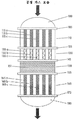
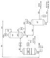
도 1a는, SSOI 반응기의 제1 구현예에 대한 튜브측(공정)의 특징들을 나타내는 측면도이다.
도 1b는, SSOI 반응기의 제1 구현예에 대한 셸측(냉매)의 특징들을 나타내는 측면도이다.
도 1c는, SSOI 반응기의 제1 구현예에 대한 튜브시트 배열을 나타내는 평면도다.
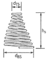
도 1d는, 스프링 모양을 유지하는 원추형 촉매의 측면도이다.
도 1e는, 클립 모양을 유지하는 촉매의 평면도다.
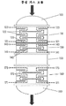
도 2는, SSOI 반응기의 제2 구현예에 대한 튜브측(공정)의 특징들을 나타내는 측면도이다.
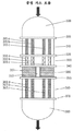
도 3a는, SSOI 반응기의 제3 구현예에 대한 튜브측(공정)의 특징들을 나타내는 측면도이다.
도 3b는, SSOI 반응기의 제3 구현예에 대한 셸측(냉매)의 특징들을 나타내는 측면도이다.
도 4는, 보충적 산화제 첨가를 위한 혼합 수단을 포함하는, SSOI 반응기의 하나의 구현예에 대한 튜브측(공정)의 특징들을 나타내는 측면도이다.
도 5는, 보충적 산화제 첨가를 위한 혼합 수단을 포함하는, SSOI 반응기의 또 다른 구현예에 대한 튜브측(공정)의 특징들을 나타내는 측면도이다.
도 6은, 보충적 산화제 첨가를 위한 벤츄리 혼합기의 횡단 측면도이다.
도 7은, 아세트산 수율(%) 대 제2 반응단 압력 간 관계를 나타내는 그래프이다.
도 8은, 본 발명의 SSOI 반응기와 무용매 아크릴산 수집 및 정제 시스템을 포함하는, 아크릴산 제조용 통합 공정에 관한 하나의 구현예다.1A is a side view showing the characteristics of the tube side (process) for the first embodiment of the SSOI reactor.
1B is a side view showing the features of the shell side (refrigerant) for the first embodiment of the SSOI reactor.
1C is a plan view showing a tube sheet arrangement for a first embodiment of an SSOI reactor.
1D is a side view of a conical catalyst maintaining a spring shape.
1E is a plan view of the catalyst maintaining the clip shape.
2 is a side view showing the characteristics of the tube side (process) for the second embodiment of the SSOI reactor.
3A is a side view showing the characteristics of the tube side (process) for the third embodiment of the SSOI reactor.
3B is a side view showing features of the shell side (refrigerant) for a third embodiment of the SSOI reactor.
4 is a side view showing the characteristics of the tube side (process) for one embodiment of the SSOI reactor, including mixing means for supplemental oxidizing agent addition.
5 is a side view showing the characteristics of the tube side (process) for another embodiment of the SSOI reactor, including mixing means for supplemental oxidizing agent addition.
6 is a cross-sectional side view of a Venturi mixer for adding supplemental oxidizers.
7 is a graph showing the relationship between acetic acid yield (%) and second reaction stage pressure.
8 is an embodiment of the integrated process for the production of acrylic acid, including the SSOI reactor and solvent-free acrylic acid collection and purification system of the present invention.
전술된 일반적인 설명과 이하 상세한 설명은 둘 다 본 교시 내용을 예시 및 설명하기 위한 것일 뿐 제한하는 것은 아님이 이해되어야 한다. 본 출원에 인용된 모든 특허들 및 특허 출원들은 명백히 임의의 목적으로 전체가 참조로 포함되어 있다. 포함된 참고 문헌들에서의 용어의 정의들이 본 교시 내용들에 제공된 정의들과 상이한 것으로 보일 때, 본 교시 내용들에 제공된 정의들이 우선할 것이다. 본 교시 내용들에 논의된 온도, 치수, 유량, 농도, 시간 등의 앞에는 "약"이 암시되어 있는데, 이는 본 교시 내용의 범주 내에 약간의 미미한 편차들이 있다는 것임이 이해될 것이다.It should be understood that the above general description and the following detailed description are both intended to illustrate and explain the content of the present teachings, and are not limiting. All patents and patent applications cited in this application are expressly incorporated by reference in their entirety for any purpose. When the definitions of terms in the included references appear to differ from the definitions provided in the present teachings, the definitions provided in the present teachings shall prevail. It will be understood that "about" is implied before the temperature, dimension, flow rate, concentration, time, etc. discussed in the present teachings, it will be understood that there are some slight deviations within the scope of the present teachings.
달리 특정되지 않는 한, 본원에 기술된 본 교시 내용들과 연관되어 사용된 과학 용어들 및 기술 용어들은 당업자들에 의해 일반적으로 이해되는 의미들을 가질 것이다. 또한, 내용상 달리 요구되지 않는 한, 단수인 용어들은 복수인 용어들도 포함할 것이고, 복수인 용어들은 단수인 용어들도 포함할 것이다. 일반적으로 셸 앤드 튜브형 반응기 디자인, 아크릴산 생산 및 산화 반응과 연관하여 사용되는 명명법과, 셸 앤드 튜브형 반응기 디자인, 아크릴산 생산 및 산화 반응에 관한 기법과 연관하여 사용되는 명명법은 당업계에 널리 알려져 있으며 일반적으로 사용되는 것이다. 다음과 같은 용어들이 본원에 제공된 구현예에 따라서 사용될 때, 이 용어들은 달리 나타내어지지 않는 한 다음과 같은 의미들을 가지는 것으로 이해되어야 할 것이다:Unless otherwise specified, scientific terms and technical terms used in connection with the present teachings described herein will have meanings generally understood by those of ordinary skill in the art. In addition, unless otherwise required by context, singular terms shall also include plural terms, and plural terms shall also include the singular terms. The nomenclature commonly used in connection with shell and tubular reactor design, acrylic acid production and oxidation reactions, and the nomenclature used in connection with shell and tubular reactor design, acrylic acid production and oxidation reaction techniques are well known in the art and generally It is used. When the following terms are used in accordance with the embodiments provided herein, these terms should be understood to have the following meanings unless otherwise indicated:
본원에 사용된 어구 "단간 열 교환기" 또는 "ISHX"란, 단일 반응기의 단들 사이에 위치하는 열 교환기를 말한다. 예를 들어, ISHX는 제1 반응단과 제2 반응단 사이에 위치할 수 있다.The phrase "interstage heat exchanger" or "ISHX" as used herein refers to a heat exchanger located between stages of a single reactor. For example, ISHX can be located between the first and second reaction stages.
어구 "통합형 단간 열 교환기" 또는 "통합형 ISHX"란, 반응단의 반응 튜브들과 동축을 이루며 연속적으로 존재하는 튜브들을 포함하는 열 교환기를 말한다.The phrase "integrated interstage heat exchanger" or "integrated ISHX" refers to a heat exchanger comprising tubes continuously present coaxially with the reaction tubes of the reaction stage.
어구 "개방형 단간" 또는 "OIS"란, 반응 튜브들은 포함하지 않고, 단일 반응기 내 단들 사이 또는 단일 반응기의 단과 단간 열 교환기 사이에 위치하는 영역을 말한다. 예를 들어, OIS는 단간 열 교환기와 제2 반응단 사이에 위치할 수 있다.The phrase "open end-to-end" or "OIS" refers to a region that does not include reaction tubes and is located between stages in a single reactor or between stages and stage-to-stage heat exchangers in a single reactor. For example, the OIS can be located between the interstage heat exchanger and the second reaction stage.
본원에 사용된 어구 "고 표면적 재료" 및 이의 변형 어구는, 표면적 대 벌크 용적 비가 78.7 ㎡/㎥(24 ft2/ft3) 이상인 재료를 말한다.As used herein, the phrase “high surface area material” and modified phrases thereof refer to a material having a surface area to bulk volume ratio of 78.7 m 2 /m 3 (24 ft 2 /ft 3 ) or more.
본원에 사용된 용어 "비활성 재료"란, 공급 재료 또는 반응 생성물의 반응을 촉진하는데 있어서 실질적으로 효과가 없는 재료를 의미한다. 예를 들어, 프로필렌의 산화를 통해서 아크릴산을 생산하는 반응기에 있어서, 비활성 재료는 프로필렌의 산화를 촉진하거나 아크롤레인의 산화를 촉진함에 있어서 실질적으로 효과가 없는 재료이다.As used herein, the term “inactive material” means a material that is substantially ineffective in promoting the reaction of the feed material or reaction product. For example, in a reactor that produces acrylic acid through oxidation of propylene, the inert material is a material that is substantially ineffective in promoting oxidation of propylene or promoting oxidation of acrolein.
본원에 사용된 용어 "안정적인 재료"란, 공정 온도, 공정 작동압 또는 공정에 관여하는 화학 성분들에 노출되었을 때 변형, 용융, 증발, 분해 또는 연소되지 않는 재료를 말한다.As used herein, the term “stable material” refers to a material that does not deform, melt, evaporate, decompose or burn when exposed to process temperatures, process operating pressures or chemical components involved in the process.
본원에 사용된 용어 "계면"이란, 2 개의 인접한 반응기 내 구획들간 경계를 말한다. 용어 "연결부"란, 계면에 있는, 인접한 반응기 내 구획들간 원주형 접촉 지점을 말하는 것으로서, 일시적으로 형성되는 것이거나 영구적으로 형성되는 것일 수 있다. 용어 "튜브시트"란, 계면에 배치되어 있는 편평한 표면으로서, 실질적으로 전체 반응기 횡단면에 걸쳐 확장되어 있고, 반응 튜브들의 말단부들이 관통하는 구멍을 다수 개 포함하는 표면을 말한다. 반응 튜브들의 말단들은 공지의 방법, 예를 들어 용접이나 롤링에 의해 튜브시트에 부착되며, 이 튜브시트는 그 외곽 원주에서 용기 셸과 추가로 부착되어, 셸측 냉매가 하나의 구획에서 다른 구획으로 통과하는 것을 막아준다. 용어 "단간 배플"이란, 계면에 배치된 편평한 표면을 말하는데, 여기서 상기 표면은 실질적으로 전체 반응기 횡단면에 걸쳐 확장되어 있고, 반응 튜브들이 관통하는 구멍을 다수 개 포함한다. 그러나 튜브시트와는 달리, 반응 튜브들은 배플에 부착되어 있지 않고, 셸측 냉매들의 유체 소통은 인접한 구획들간에 허용된다. 마지막으로, 용어 "분절 배플"이란, 계면에 배치되어 있지 않은 편평한 표면을 말하는데, 여기서 상기 표면은 반응기 횡단면의 오로지 일부에 걸쳐서만 확장되어 있고, 반응 튜브들이 관통하는 구멍을 다수 개 포함한다. 단간 배플이 존재하는 관계로, 반응 튜브들은 분절 배플에 부착되어 있지 않으며, 셸측 냉매의 유체 소통은 분절 배플의 반대편 표면들간에 허용된다.The term "interface" as used herein refers to the boundary between compartments in two adjacent reactors. The term "connection" refers to a circumferential contact point between compartments in adjacent reactors at the interface, which may be temporarily formed or permanently formed. The term “tubesheet” refers to a surface that is a flat surface disposed at the interface, that extends substantially across the entire reactor cross-section, and that includes a number of holes through which the distal ends of the reaction tubes pass. The ends of the reaction tubes are attached to the tubesheet by a known method, for example welding or rolling, which is further attached to the vessel shell at its outer circumference, so that the shell-side refrigerant passes from one compartment to another. It prevents you from doing it. The term "intermittent baffle" refers to a flat surface disposed at the interface, wherein the surface extends substantially across the entire reactor cross-section and includes a number of holes through which the reaction tubes pass. However, unlike the tubesheet, the reaction tubes are not attached to the baffle, and fluid communication of the shell-side refrigerants is allowed between adjacent compartments. Finally, the term “segmented baffle” refers to a flat surface that is not disposed at the interface, where the surface extends only over a portion of the reactor cross-section and includes a number of holes through which the reaction tubes pass. Due to the presence of an inter-stage baffle, the reaction tubes are not attached to the segment baffle, and fluid communication of the shell-side refrigerant is allowed between the opposite surfaces of the segment baffle.
용어 "직경" 및 "횡단면적"은, 튜브와 관련하여 사용될 때 튜브의 형태보다는 튜브의 크기를 정의하는 데 사용된다. 본원에 제공된 실시예들에서는 횡단면이 원형인 튜브들이 사용되지만, 기타 다른 형태를 가지는 튜브들도 사용될 수 있다. 기타 다른 형태를 가지는 튜브에 있어서, 당업자는, 대안적 형태로 인한 임의의 변형을 고려하여(예를 들어, 열 전달용인지 아니면 질량 전달용인지 등을 고려하여) 횡단면적을 결정함으로써 본원에 개시된 직경들이 대안적 형태들에 적당한 치수로 전환될 수 있음을 이해할 것이다. 용어 "직경" 및 "횡단면적"은, 튜브 입구의 직경 또는 횡단면적, 즉 튜브 입구의 내경 또는 횡단면적을 말하는 데 사용된다.The terms "diameter" and "cross-sectional area" are used to define the size of the tube rather than the shape of the tube when used in connection with the tube. In the embodiments provided herein, tubes having a circular cross-section are used, but tubes having other shapes may also be used. For tubes having other shapes, those skilled in the art are disclosed herein by determining the cross-sectional area in consideration of any variations due to alternative shapes (eg, for heat transfer or mass transfer). It will be understood that the diameters can be converted to dimensions suitable for alternative shapes. The terms "diameter" and "cross-sectional area" are used to refer to the diameter or cross-sectional area of the tube inlet, that is, the inner diameter or cross-sectional area of the tube entrance.
본원에 사용된 용어 "상향류" 및 "하향류"는, 중력에 대해 유체가 반응기를 통과하는 방향에 관한 것이다. 상향류는 중력에 맞서며 진행하는 상향 수직 공정 흐름을 말하는 것이다. 하향류는 중력 방향으로 진행하는 하향 공정 흐름을 말하는 것이다.As used herein, the terms "upstream" and "downstream" relate to the direction in which fluid passes through the reactor against gravity. Upstream refers to the upward vertical process flow against gravity. Downstream refers to the downstream process flow in the direction of gravity.
용어 "체류 시간"이란, 하나 이상의 특정 구획들 내에서 가스가 소비하는 시간의 양을 말한다. 예를 들어, 체류 시간은 ISHX 내에서 가스가 소비하는 시간의 양을 말할 수 있다. 이와 유사하게, 체류 시간은 다수의 구획들 내에서 소비되는 시간의 양, 예를 들어 ISHX와 OIS 영역 내에서 소비되는 시간의 총량을 말할 수 있다. 달리 특정되지 않는 한, 반응기 내 공정 가스 흐름의 체류 시간은 240℃ 및 30 psia(2 atm) 압력의 기준 조건에서 측정된다.The term "residence time" refers to the amount of time the gas spends in one or more specific compartments. For example, residence time can refer to the amount of time gas is consumed within ISHX. Similarly, residence time can refer to the amount of time spent in multiple compartments, for example the total amount of time spent in the ISHX and OIS regions. Unless otherwise specified, the residence time of the process gas flow in the reactor is measured at reference conditions of 240° C. and 30 psia (2 atm) pressure.
하나 이상의 구현예에서, SSOI 반응기는,In one or more embodiments, the SSOI reactor,
a) 유입구 반응기 헤드;a) inlet reactor head;
b) 셸 앤드 튜브형 제1 반응단;b) a shell and tubular first reaction stage;
c) 통합형 단간 열 교환기;c) integrated interstage heat exchanger;
d) 개방형 단간 영역;d) open interstitial areas;
e) 셸 앤드 튜브형 제2 반응단; 및e) a shell and tube type second reaction stage; And
f) 유출구 반응기 헤드;f) outlet reactor head;
를 공정 흐름 순서로 포함한다.Is included in the process flow order.
제1 반응단("R1")은, 각각이 촉매, 예를 들어 R1 촉매로 충전될 수 있는 다수의 반응 튜브들을 포함할 수 있다. 상기 R1 촉매가 프로필렌을 산화시켜 아크릴산을 형성하는데 사용될 때, 이 R1 촉매는 몰리브덴, 비스무트 및 철의 산화물들로부터 선택되는 MMO 촉매일 수 있다.The first reaction stage ("R1") may include a number of reaction tubes, each of which can be filled with a catalyst, for example an R1 catalyst. When the R1 catalyst is used to oxidize propylene to form acrylic acid, the R1 catalyst can be an MMO catalyst selected from oxides of molybdenum, bismuth and iron.
제1 반응단은 셸측 냉매를 포함할 수 있다. 당업자는, 특정 용도에 따라서 열 전달 필요성이 충족되도록 냉매와 냉매 순환이 선택 및 디자인될 수 있음을 이해할 것이다. The first reaction stage may include a shell-side refrigerant. Those skilled in the art will understand that refrigerant and refrigerant circulation can be selected and designed to meet the need for heat transfer depending on the particular application.
제2 반응단("R2")은 다수의 반응 튜브들을 포함할 수 있다. R2 반응 튜브들은 제2 단의 반응을 촉진하는 촉매(R2 촉매)로 충전될 수 있다. 아크롤레인이 R2에서 산화되어 아크릴산을 형성하는 예시적 반응에 있어서, R2 촉매는 몰리브덴 및 바나듐 산화물들로부터 선택되는 MMO를 포함할 수 있다. 제2 반응단의 셸측은 냉매를 포함할 수 있다. 제2 반응단의 냉매는 제1 반응단의 냉매와는 독립하여 제어될 수 있다. 대안적으로, 제2 반응단의 냉매는 제1 반응단의 냉매와 함께 제어될 수 있다.The second reaction stage (“R2”) may include a plurality of reaction tubes. The R2 reaction tubes can be filled with a catalyst (R2 catalyst) that promotes the reaction of the second stage. In an exemplary reaction in which acrolein is oxidized at R2 to form acrylic acid, the R2 catalyst may include MMO selected from molybdenum and vanadium oxides. The shell side of the second reaction stage may include a refrigerant. The refrigerant in the second reaction stage can be controlled independently of the refrigerant in the first reaction stage. Alternatively, the refrigerant in the second reaction stage can be controlled together with the refrigerant in the first reaction stage.
하나 이상의 구현예에서, ISHX는 셸측 냉매를 포함할 수 있다. ISHX 냉매는 개별적으로 제어될 수 있거나, 아니면 제1 반응단 냉매와 함께 제어될 수 있다. 하나 이상의 구현예에서, ISHX 냉매는 제1 반응단 냉매와는 독립적으로 제어된다. 하나 이상의 구현예에 따르면, ISHX 냉매는 ISHX를 빠져나가는 공정 가스의 온도를 240℃ 내지 280℃로 유지한다.In one or more embodiments, the ISHX can include a shell-side refrigerant. The ISHX refrigerant can be individually controlled, or it can be controlled together with the first reaction stage refrigerant. In one or more embodiments, the ISHX refrigerant is controlled independently of the first reaction stage refrigerant. According to one or more embodiments, the ISHX refrigerant maintains the temperature of the process gas exiting ISHX between 240°C and 280°C.
본 개시 내용의 하나 이상의 구현예에 있어서, R1 및 R2 반응 튜브들은 직경 또는 횡단면적이 상이할 수 있다. 예를 들어, R2 반응 튜브들은 R1 반응 튜브들보다 더 클 수 있다. 대안적으로, R1 및 R2 반응 튜브들은 직경과 횡단면적이 동일할 수 있다. 하나 이상의 구현예에서, R2 반응 튜브들의 횡단면적은 R1 반응 튜브들의 횡단면적보다 25% 이상 클 수 있다. 추가의 구현예에서, R2 반응 튜브들의 횡단면적은 R1 반응 튜브들의 횡단면적보다 50% 이상 클 수 있다.In one or more embodiments of the present disclosure, the R1 and R2 reaction tubes can differ in diameter or cross-sectional area. For example, R2 reaction tubes can be larger than R1 reaction tubes. Alternatively, the R1 and R2 reaction tubes may have the same diameter and cross-sectional area. In one or more embodiments, the cross-sectional area of the R2 reaction tubes can be at least 25% greater than the cross-sectional area of the R1 reaction tubes. In a further embodiment, the cross-sectional area of the R2 reaction tubes can be at least 50% greater than that of the R1 reaction tubes.
하나 이상의 구현예에서, R1 반응 튜브들의 직경은 22.3 ㎜(0.878 in) 이하일 수 있다. 다른 구현예에서, R1 반응 튜브들의 직경은 22.3 ㎜(0.878 in) 이상, 예를 들어 25.4 ㎜(1 in) 이상일 수 있다.In one or more embodiments, the diameter of the R1 reaction tubes may be 22.3 mm (0.878 in) or less. In other embodiments, the diameter of the R1 reaction tubes can be greater than or equal to 22.3 mm (0.878 in), such as greater than or equal to 25.4 mm (1 in).
하나 이상의 구현예에서, SSOI 반응기 내 제2 반응단의 튜브들의 내경은 22.3 ㎜ 초과일 수 있다. 하나 이상의 구현예에서, R1 및 R2 반응 튜브들의 직경은 22.3 ㎜(0.878 in) 초과이다. 추가의 구현예에서, SSOI 반응기 내 제2 반응단의 튜브들의 내경은 23.6 ㎜ 내지 50 ㎜의 범위이다. 하나 이상의 구현예에서, SSOI 반응기 내 제2 반응단의 튜브들의 내경은 25.4 ㎜(1 in) 이상이다. 본 개시 내용의 구현예에 따르면, 제2 반응단의 튜브들의 길이는 4,500 ㎜(177 in) 이하이다.In one or more embodiments, the inner diameter of the tubes of the second reaction stage in the SSOI reactor may be greater than 22.3 mm. In one or more embodiments, the diameter of the R1 and R2 reaction tubes is greater than 22.3 mm (0.878 in). In a further embodiment, the inner diameter of the tubes of the second reaction stage in the SSOI reactor ranges from 23.6 mm to 50 mm. In one or more embodiments, the inner diameter of the tubes of the second reaction stage in the SSOI reactor is 25.4 mm (1 in) or more. According to an embodiment of the present disclosure, the length of the tubes of the second reaction stage is 4,500 mm (177 in) or less.
직경이 더 큰 튜브들의 열 제거에 미치는 부정적인 영향력은 기타 다른 디자인 변수들, 예를 들어 셸측 배플의 개수, 배플의 기하학적 형태 및 배치, 튜브시트 배열 및 튜브들간 간격(튜브 피치라고도 알려짐), 냉각 염의 순환 유량, 그리고 냉각 염의 공급 온도 중 하나 이상을 적절히 조정함으로써 보상될 수 있다. 예를 들어 하나의 구현예에서, 반응기 셸을 거치는 염의 순환 유량이 적어지면, 염 순환 펌프에 소비되는 전력이 최소화되고; 이와 같은 디자인 철학은 일반적으로 반응기 셸을 거치는 염의 온도 상승폭(염의 유입 온도에 대한 염의 유출 온도)을 14℃ 내지 17℃(25℉ 내지 30℉)로 만들 수 있다. 대안적 구현예에서, 높은 염 순환 유량이 적용되고, 반응기 셸을 거치는 염의 온도 상승폭은 단지 1℃ 내지 3℃(2℉ 내지 5℉)의 범위로 제한된다.The negative impact on heat removal of larger diameter tubes is due to other design variables, such as the number of baffles on the shell side, the geometry and placement of the baffles, tubesheet arrangement and spacing between tubes (also known as tube pitch), cooling salt It can be compensated by properly adjusting one or more of the circulating flow rate and the supply temperature of the cooling salt. For example, in one embodiment, when the circulating flow rate of the salt through the reactor shell is reduced, the power consumed by the salt circulation pump is minimized; This design philosophy can generally make the temperature rise of the salt through the reactor shell (the salt's inlet temperature versus the salt's inlet temperature) from 14°C to 17°C (25°F to 30°F). In an alternative embodiment, a high salt circulation flow rate is applied, and the temperature rise of the salt through the reactor shell is limited to a range of only 2° C. to 3° C. (2° F. to 5° F.).
이와 같은 디자인은 HTRI 등으로부터 시판중인 디자인 소프트웨어를 사용하여 열 교환기 디자인 업계의 당업자에 의해 조정될 수 있으며; 대안적으로 냉각 시스템 디자인 서비스는 확립된 반응기 제작 업체, 예를 들어 맨 터보 아게(MAN Turbo AG)(구 데겐도르페 베르프트 앤드 아이젠바우 게엠베하(Deggendorfer Werft and Eisenbau GmbH))(본 업체는 자체적으로 잘 확립된 디자인 규칙과 방법들을 사용할 것임)에 의해 외주 제작될 수 있다.Such a design can be adjusted by those skilled in the heat exchanger design industry using design software commercially available from HTRI et al.; Alternately, the cooling system design service can be achieved by established reactor manufacturers, e.g. MAN Turbo AG (formerly Deggendorfer Werft and Eisenbau GmbH) As well as using well-established design rules and methods).
이와 유사하게, R1 및 R2 내 반응 튜브들의 개수는 동일하거나 상이할 수 있다. 하나 이상의 구현예에서, R1 반응 튜브들의 개수는 R2 반응 튜브들의 개수보다 많을 수 있다. 하나 이상의 추가의 구현예에서, R1 반응 튜브들의 개수는 R2 반응 튜브들의 개수보다 많을 수 있으며, R2 반응 튜브들의 직경 또는 횡단면적은 R1 반응 튜브들의 직경 또는 횡단면적보다 클 수 있다.Similarly, the number of reaction tubes in R1 and R2 can be the same or different. In one or more embodiments, the number of R1 reaction tubes can be greater than the number of R2 reaction tubes. In one or more additional embodiments, the number of R1 reaction tubes may be greater than the number of R2 reaction tubes, and the diameter or cross-sectional area of the R2 reaction tubes may be greater than the diameter or cross-sectional area of the R1 reaction tubes.
본원에 개시된 SSOI 반응기들은 상향류 작동 또는 하향류 작동을 위해 구성될 수 있다. 하나 이상의 구현예에서, SSOI 반응기들은 상향류 작동을 위해 구성된다. 상향류 SSOI 반응기에 있어서, 유입구 반응기 헤드는 SSOI 반응기의 하부에 위치하고 있으며, 유출구 반응기 헤드는 SSOI 반응기의 상부에 위치하고 있다.The SSOI reactors disclosed herein can be configured for upstream operation or downstream operation. In one or more embodiments, SSOI reactors are configured for upstream operation. In the upstream SSOI reactor, the inlet reactor head is located at the bottom of the SSOI reactor, and the outlet reactor head is located at the top of the SSOI reactor.
하나 이상의 구현예에서, OIS 영역은 보충적 산화제 공급물을 포함한다. 보충적 산화제 공급물이 존재할 때, OIS 영역은 보충적 산화제 혼합 조립체를 추가로 포함할 수도 있다.In one or more embodiments, the OIS region comprises a supplemental oxidant feed. When a supplemental oxidant feed is present, the OIS region may further include a supplemental oxidant mixing assembly.
프로필렌 산화로부터 아크릴산이 생산되는 구현예에서, ISHX 및 OIS 둘 다의 내부 체류 시간의 합(본원에서 "단간 체류 시간"이라고도 알려져 있음)은 3 초 이하이다. 하나 이상의 구현예에서, ISHX 내부 체류 시간은 1.5 초 미만이다.In embodiments in which acrylic acid is produced from propylene oxidation, the sum of the internal residence times of both ISHX and OIS (also known herein as “short residence time”) is 3 seconds or less. In one or more embodiments, the ISHX internal residence time is less than 1.5 seconds.
하나 이상의 구현예에서, 작동중인 SSOI 반응기의 공정 가스는 하나 이상의 온라인 분석 장치, 예를 들어 크로마토그래피 장치, 근적외선("NIR") 분석 장치, 파장 가변 다이오드 레이저("TDL") 분석 장치 또는 로마 분광기를 사용하여 미반응 프로필렌 농도와 미반응 아크롤레인 농도에 대해 모니터될 수 있으며, 제1 반응단과 제2 반응단으로의 염 공급 온도는 프로필렌 및 아크롤레인의 전환을 제어하도록 조정될 수 있다. 하나의 구현예에서, 제1 단 냉각 염의 공급 온도(TR1염)는 프로필렌 전환율이 94% 이상, 95% 이상 또는 96.5% 이상으로 유지되도록 조정될 수 있다.In one or more embodiments, the process gas of an SSOI reactor in operation may include one or more on-line analytical devices, such as chromatography devices, near infrared ("NIR") analysis devices, tunable diode laser ("TDL") analysis devices or Roman spectroscopy. Can be monitored for unreacted propylene concentration and unreacted acrolein concentration, and the salt feed temperature to the first and second reaction stages can be adjusted to control the conversion of propylene and acrolein. In one embodiment, the feed temperature of the first stage cooling salt (T R1 salt ) may be adjusted such that the propylene conversion is maintained at 94% or higher, 95% or higher, or 96.5% or higher.
다른 구현예에서, 제1 단 냉각 염의 공급 온도(TR1염)는 SSOI 반응기 생성 가스 중 미반응 프로필렌 농도가 0.05 mol% 내지 0.35 mol%, 예를 들어 0.13 mol% 내지 0.26 mol%로 유지되도록 조정될 수 있다. 하나의 구현예에서, 제2 단 냉각 염의 공급 온도(TR2염)는 아크롤레인 전환율이 98% 이상, 예를 들어 99% 이상 또는 99.5% 이상으로 유지되도록 조정될 수 있다.In another embodiment, the feed temperature of the first stage cooling salt (T R1 salt ) is adjusted such that the unreacted propylene concentration in the SSOI reactor product gas is maintained at 0.05 mol% to 0.35 mol%, for example 0.13 mol% to 0.26 mol%. Can be. In one embodiment, the feed temperature of the second stage cooling salt (T R2 salt ) can be adjusted such that the acrolein conversion is maintained at 98% or higher, for example at least 99% or at least 99.5%.
다른 구현예에서, 제2 반응단 냉각 염의 공급 온도(TR2염)는 SSOI 반응기 생성 가스 중 미반응 아크롤레인 농도가 500 ppm 이하, 예를 들어 300 ppm 이하로 유지되도록 조정될 수 있다.In other embodiments, the supply temperature of the second reaction stage cooling salt (T R2 salt ) may be adjusted such that the unreacted acrolein concentration in the SSOI reactor product gas is maintained at 500 ppm or less, such as 300 ppm or less.
하나 이상의 구현예에서, 온도 측정 장치, 예를 들어 열전대 또는 열 저항 장치(Resistance Thermal Device; RTD)는 반응 시스템 내에 제공되어, 공정 작동 조건을 모니터하는데 사용될 수 있고, 선택적으로는 반응 시스템용 안전 계기 시스템(SIS) 내부의 센서의 역할을 할 수 있다. 개별 및 멀티포인트 E-타입, J-타입 및 K-타입 열전대는 모두 본 발명의 SSOI 반응기에 사용되기 적당하며, 다수의 공급처, 예를 들어 STI 매뉴팩처링 인코포레이티드(STI manufacturing Inc.)(미국 텍사스주 윌리스 소재); 왓로우 엘렉트릭 매뉴팩처링 컴퍼니(Watlow Electric Manufacturing Company)(미국 미주리주 세인트루이스 소재); 산델리우스 인스트루먼츠, 인코포레이티드(Sandelius Instruments, Inc)(미국 텍사스주 휴스톤 소재) 및 가예스코 인터내셔널 인코포레이티드(Gayesco International Inc.)(미국 텍사스주 파사데나 소재)로부터 시판되고 있다.In one or more embodiments, a temperature measuring device, such as a thermocouple or resistance thermal device (RTD), is provided within the reaction system and can be used to monitor process operating conditions, and optionally a safety instrument for the reaction system. It can serve as a sensor inside the system (SIS). Individual and multipoint E-type, J-type and K-type thermocouples are all suitable for use in the SSOI reactor of the present invention, and have multiple sources, such as STI Manufacturing Inc. (USA) Willis, Texas); Watlow Electric Manufacturing Company (St. Louis, Missouri, USA); Commercially available from Sandelius Instruments, Inc. (Houston, Tex.) and Kayesco International Inc. (Pasadena, Tex.).
하나 이상의 열전대가 유입구 헤드, 유출구 헤드, 유입구 파이프, 유출구 파이프, 그리고 개방형 단간 영역 중 하나 이상의 내부에 선택적으로 배치될 수 있다. 하나의 구현예에서, 다수의 열전대는 SIS 셧다운 시스템과 함께 사용되도록 반응기 유입구 헤드 내부에 배치될 수 있다. 하나 이상의 구현예에 따르면, 4개 이상의 열전대가 개방형 단간 영역 내부에 설치될 수 있으며, 이러한 열전대들은 단간 영역 전반에 고르게 분포될 수 있다. 뿐만 아니라, 열전대들은 선택적으로 반응기 내부의 튜브시트들에 직접 부착되어 있을 수도 있다.One or more thermocouples may be selectively disposed within one or more of the inlet head, outlet head, inlet pipe, outlet pipe, and open inter-span area. In one embodiment, multiple thermocouples can be placed inside the reactor inlet head for use with the SIS shutdown system. According to one or more embodiments, four or more thermocouples may be installed inside the open, short-term region, and these thermocouples may be evenly distributed throughout the short-term region. In addition, thermocouples may optionally be attached directly to the tubesheets inside the reactor.
튜브의 축을 따라서 다양한 간격으로 떨어져 있는, 공정측 촉매 온도 모니터용 멀티포인트 공정 열전대 다수 개가 반응기의 튜브들 내부에 사용될 수 있다. 하나 이상의 구현예에서, 반응기의 길이 방향에 따른 셸측 염 온도를 모니터하기 위해서 멀티포인트 염 열전대 다수 개는 반응기 튜브들의 내부에 배치될 수 있다. 그러나, 멀티포인트 공정 열전대 및 멀티포인트 염 열전대는 동일한 반응기 튜브 내에 공존할 수 없다는 것에 주목하여야 한다.Multiple multipoint process thermocouples for process-side catalyst temperature monitoring, spaced at various intervals along the axis of the tube, can be used inside the tubes of the reactor. In one or more embodiments, multiple multipoint salt thermocouples may be placed inside reactor tubes to monitor the shell-side salt temperature along the length of the reactor. However, it should be noted that multipoint process thermocouples and multipoint salt thermocouples cannot coexist in the same reactor tube.
하나의 구현예에서, 멀티포인트 공정 열전대 조립체 자체의 길이 방향을 따라서 다양한 간격을 두고 배치되어 있으며, 외경이 3.2 ㎜인 시스 내부에 수용되어 있는 14 개의 열전대 접합부를 포함하는 멀티포인트 공정 열전대 조립체는 내경이 22.3 ㎜인 제1 반응단 튜브 내부에 사용된다. 다른 구현예에서, 멀티포인트 공정 열전대 조립체 자체의 길이 방향을 따라서 동일한 간격을 두고 배치되어 있으며, 외경이 6 ㎜인 시스 내부에 수용되어 있는 10 개 이상의 열전대 접합부를 포함하는 멀티포인트 공정 열전대 조립체는 내경이 25.4 ㎜인 제1 반응단 튜브 내부에 사용된다. 어느 하나의 구현예에서, 공정 열전대 조립체는 반응기 튜브의 중앙선을 따라서 배향될 수 있고, 촉매와 비활성 재료는 튜브에 잔류하는 고리 모양 공간 내에 충전될 수 있다.In one embodiment, the multipoint process thermocouple assembly is arranged at various intervals along the longitudinal direction of the multipoint process thermocouple assembly itself, and the multipoint process thermocouple assembly includes 14 thermocouple junctions housed inside a sheath having an outer diameter of 3.2 mm. It is used inside the first reaction stage tube of 22.3 mm. In another embodiment, the multipoint process thermocouple assembly is disposed at equal intervals along the longitudinal direction of the multipoint process thermocouple assembly itself, and the multipoint process thermocouple assembly comprises 10 or more thermocouple junctions housed inside a sheath having an outer diameter of 6 mm. It is used inside the first reaction end tube of 25.4 mm. In either embodiment, the process thermocouple assembly can be oriented along the center line of the reactor tube, and the catalyst and inert material can be filled into the annular space remaining in the tube.
하나 이상의 구현예에서, 4 개 이상의 반응기 튜브들, 예를 들어 6 개 이상의 튜브들 또는 10 개 이상의 튜브들은 상기된 바와 같은 멀티포인트 공정 열전대 조립체들과 끼워 맞추어질 수 있다. 이와 유사하게, 하나의 구현예에서, 멀티포인트 염 열전대 조립체 자체의 길이 방향을 따라서 동일한 간격을 두고 배치되어 있으며, 외경이 3.2 ㎜인 시스 내부에 수용되어 있는 4 개의 열전대 접합부를 포함하는 멀티포인트 염 열전대 조립체는 내경이 22.3 ㎜인 제1 반응단 튜브 내부에 사용된다. In one or more embodiments, four or more reactor tubes, such as six or more tubes or ten or more tubes, can be fitted with multipoint process thermocouple assemblies as described above. Similarly, in one embodiment, a multipoint salt comprising four thermocouple junctions spaced at equal intervals along the length of the multipoint salt thermocouple assembly itself and housed inside a sheath having an outer diameter of 3.2 mm. The thermocouple assembly is used inside a first reaction stage tube with an inner diameter of 22.3 mm.
대안적 구현예에서, 멀티포인트 염 열전대 조립체 자체의 길이 방향을 따라서 동일한 간격을 두고 배치되어 있으며, 외경이 6 ㎜인 시스 내부에 수용되어 있는 3 개 이상의 열전대 접합부를 포함하는 멀티포인트 염 열전대 조립체는 내경이 25.4 ㎜인 제1 반응단 튜브 내부에 사용된다. 4개 이상의 반응기 튜브들, 예를 들어 6개 이상의 튜브들 또는 10개 이상의 튜브들은 상기된 바와 같은 멀티포인트 염 열전대 조립체들과 끼워 맞추어질 수 있다. 하나의 구현예에서, 염 열전대 조립체는 반응기 튜브의 중앙선을 따라서 배향될 수 있고, 비활성 구체들은 튜브에 잔류하는 고리 모양 공간 내에 충전되며, 밀봉 가능한 캡이나 플러그는 적어도 튜브의 상류 말단에 배치되어, 축 방향으로 흐르는 공정 가스 흐름이 튜브를 거치지 못하도록 막아준다. 대안적 구현예에서, 염 열전대 조립체는 반응기 튜브의 중앙선을 따라서 배향될 수 있고, 직경이 작은(예를 들어, 직경이 4 ㎜를 넘지 않는) 비활성 입자들, 예를 들어 모래, 알루미나 분말 또는 탄화규소 그릿(grit)은 튜브에 잔류하는 고리 모양 공간 내에 충전되어, 축 방향으로 흐르는 공정 가스 흐름에 대하여 큰 저항을 제공할 수 있고; 선택적으로, 이와 같은 구현예는 적어도 튜브의 상류 말단에 밀봉 가능한 캡이나 플러그를 추가로 포함할 수도 있다.In an alternative embodiment, the multipoint salt thermocouple assembly is arranged at equal intervals along the longitudinal direction of the multipoint salt thermocouple assembly itself, and includes three or more thermocouple junctions housed inside a sheath having an outer diameter of 6 mm. Used inside the first reaction end tube with an inner diameter of 25.4 mm. Four or more reactor tubes, such as six or more tubes or ten or more tubes, can be fitted with multipoint salt thermocouple assemblies as described above. In one embodiment, the salt thermocouple assembly can be oriented along the center line of the reactor tube, the inert spheres are filled in an annular space remaining in the tube, and a sealable cap or plug is disposed at least at the upstream end of the tube, The process gas flow in the axial direction prevents it from passing through the tube. In an alternative embodiment, the salt thermocouple assembly can be oriented along the centerline of the reactor tube and inert particles of small diameter (eg, no more than 4 mm in diameter), eg sand, alumina powder or carbonization The silicon grit can be filled in an annular space remaining in the tube, providing great resistance to axially flowing process gas flows; Optionally, such an embodiment may further include a sealable cap or plug at least at the upstream end of the tube.
하나의 구현예에서, 멀티포인트 공정 열전대 조립체 자체의 길이 방향을 따라서 다양한 간격을 두고 배치되어 있으며, 외경이 3.2 ㎜인 시스 내부에 수용되어 있는 8 개 이상의 열전대 접합부를 포함하는 멀티포인트 공정 열전대 조립체는 내경이 22.3 ㎜인 제2 반응단 튜브 내부에 사용될 수 있다. 다른 구현예에서, 멀티포인트 공정 열전대 조립체 자체의 길이 방향을 따라서 동일한 간격을 두고 배치되어 있으며, 외경이 6 ㎜인 시스 내부에 수용되어 있는 10 개 이상의 열전대 접합부를 포함하는 멀티포인트 공정 열전대 조립체는 내경이 25.4 ㎜인 제2 반응단 튜브 내부에 사용될 수 있다. 공정 열전대 조립체는 반응기 튜브의 중앙선을 따라서 배향될 수 있고, 촉매 및 비활성 재료들은 튜브에 잔류하는 고리 모양 공간 내에 충전될 수 있다. 하나 이상의 구현예에서, 4 개 이상의 반응기 튜브, 예를 들어 6 개 이상의 튜브 또는 10 개 이상의 튜브는 이와 같은 멀티포인트 공정 열전대 조립체와 끼워 맞춰질 수 있다. 이와 유사하게, 하나의 구현예에서, 멀티포인트 염 열전대 조립체 자체의 길이 방향을 따라서 동일한 간격을 두고 배치되어 있으며, 외경이 3.2 ㎜인 시스 내부에 수용되어 있는 2 개 이상의 열전대 접합부를 포함하는 멀티포인트 염 열전대 조립체는 내경이 22.3 ㎜인 제2 반응단 튜브 내부에 사용될 수 있다.In one embodiment, the multipoint process thermocouple assembly is arranged at various intervals along the length direction of the multipoint process thermocouple assembly itself, and the multipoint process thermocouple assembly includes eight or more thermocouple junctions housed inside a sheath having an outer diameter of 3.2 mm. It can be used inside a second reaction stage tube having an inner diameter of 22.3 mm. In another embodiment, the multipoint process thermocouple assembly is disposed at equal intervals along the longitudinal direction of the multipoint process thermocouple assembly itself, and the multipoint process thermocouple assembly comprises 10 or more thermocouple junctions housed inside a sheath having an outer diameter of 6 mm. It can be used inside the 25.4 mm second reaction stage tube. The process thermocouple assembly can be oriented along the center line of the reactor tube, and the catalyst and inert materials can be filled into the annular space remaining in the tube. In one or more embodiments, four or more reactor tubes, such as six or more tubes or ten or more tubes, can be fitted with such a multipoint process thermocouple assembly. Similarly, in one embodiment, the multipoint salt thermocouple assembly itself is arranged at equal intervals along the longitudinal direction, and the multipoint comprises two or more thermocouple junctions housed inside a sheath having an outer diameter of 3.2 mm. The salt thermocouple assembly can be used inside a second reaction stage tube with an inner diameter of 22.3 mm.
대안적 구현예에서, 멀티포인트 염 열전대 조립체 자체의 길이 방향을 따라서 동일한 간격을 두고 배치되어 있으며, 외경이 6 ㎜인 시스 내부에 수용되어 있는 3 개 이상의 열전대 접합부를 포함하는 멀티포인트 염 열전대 조립체는 내경이 25.4 ㎜인 제2 반응단 튜브 내부에 사용될 수 있다. 하나 이상의 구현예에서, 4 개 이상의 반응기 튜브, 예를 들어 6 개 이상의 튜브 또는 10 개 이상의 튜브는 이와 같은 멀티포인트 염 열전대 조립체와 끼워 맞춰질 수 있다. 하나의 구현예에서, 염 열전대 조립체는 반응기 튜브의 중앙선을 따라서 배향될 수 있고, 비활성 구체들은 튜브에 잔류하는 고리 모양 공간 내에 충전될 수 있으며, 밀봉 가능한 캡 또는 플러그는 적어도 튜브의 상류 말단에 배치되어, 축 방향으로 흐르는 공정 가스 흐름이 튜브를 거치지 못하도록 막아준다. 대안적 구현예에서, 염 열전대 조립체는 반응기 튜브의 중앙선을 따라서 배향될 수 있으며, 직경이 작은(예를 들어, 직경이 4 ㎜를 넘지 않는) 비활성 입자들, 예를 들어 모래, 알루미나 분말 또는 탄화규소 그릿은 튜브에 잔류하는 고리 모양 공간 내에 충전되어, 축방향으로 흐르는 공정 가스 흐름에 대하여 큰 저항을 제공하는데; 선택적으로, 이러한 구현예는 적어도 튜브의 상류 말단부에 밀봉 가능한 캡이나 플러그를 추가로 포함할 수도 있다.In an alternative embodiment, the multipoint salt thermocouple assembly is arranged at equal intervals along the longitudinal direction of the multipoint salt thermocouple assembly itself, and includes three or more thermocouple junctions housed inside a sheath having an outer diameter of 6 mm. It can be used inside the second reaction stage tube having an inner diameter of 25.4 mm. In one or more embodiments, four or more reactor tubes, such as six or more tubes or ten or more tubes, can be fitted with such a multipoint salt thermocouple assembly. In one embodiment, the salt thermocouple assembly can be oriented along the centerline of the reactor tube, the inert spheres can be filled in an annular space remaining in the tube, and a sealable cap or plug is placed at least at the upstream end of the tube This prevents the process gas flow flowing in the axial direction from passing through the tube. In an alternative embodiment, the salt thermocouple assembly can be oriented along the centerline of the reactor tube and inert particles of small diameter (eg, no more than 4 mm in diameter), such as sand, alumina powder or carbonization The silicon grit is filled in an annular space remaining in the tube, providing great resistance to axially flowing process gas flow; Optionally, this embodiment may further include a sealable cap or plug at least at the upstream end of the tube.
도 1a, 도 1b 및 도 1c는 모두 단일 셸 개방형 단간("SSOI") 반응기 디자인에 관한 하나의 구현예를 나타내는 것이다. 본 구현예의 반응기의 셸 직경은 약 5,600 ㎜(18.4 피트)이고, 전체 길이는 15,240 ㎜(50 피트) 초과이다. 통상의 공급비와 (0℃ 및 1 atm에서 측정된) 총 공급물 가스 공간 속도 1770 hr-1 에서, 이러한 구현예에 따른 반응기의 연간 아크릴산의 명목상 생산 용량은 약 100 kT이다.1A, 1B, and 1C all represent one embodiment of a single shell open-ended inter-stage (“SSOI”) reactor design. The shell diameter of the reactor of this embodiment is about 5,600 mm (18.4 feet), and the total length is greater than 15,240 mm (50 feet). At a typical feed rate and total feed gas space velocity (measured at 0° C. and 1 atm) of 1770 hr −1 , the nominal production capacity of acrylic acid per year in the reactor according to this embodiment is about 100 kT.
(예를 들어 프로필렌, 증기, 산소 및 질소를 포함하는) 공급물 가스는 상부로부터 반응기로 들어가고(도 1a 참조), 이 반응기를 거쳐 수직 아래로 흘러내려오다가, 하부에서 반응기를 빠져 나간다. 따라서 이러한 배열은 하향류 공정 구성인 것이다.The feed gas (including for example propylene, steam, oxygen and nitrogen) enters the reactor from the top (see FIG. 1A ), flows vertically down through this reactor, and exits the reactor from the bottom. Therefore, this arrangement is a downstream configuration.
반응기의 주 구획들은 유입구 헤드(100), 제1 반응단(110)("R1"), 단간 열 교환기(130)("ISHX"), 개방형 단간 영역(150), 제2 반응단(160)("R2"), 그리고 유출구 헤드(180)를 포함한다. 달리 특정되지 않는 한, 반응기 부품 전부는 탄소강, 예를 들어 ASME SA-516 등급 70 탄소강으로 구성될 수 있다.The main sections of the reactor are the
인접 구획들간 계면(도면에서 105, 125, 145, 155 및 175로 지정된 부분)은 영구적인(예를 들어, 용접된) 연결부들을 포함할 수 있거나, 아니면 선택적으로는 분리 가능한 연결부들, 예를 들어 다수의 잠금 장치, 예를 들어 볼트 또는 클램프로 고정되어 있는 돌출된(flanged) 연결부들을 포함할 수도 있다. 도 1a의 구현예에 있어서, 계면(105 및 175)은 분리 가능한 연결부들로서, 촉매 교체시 유입구 헤드(100)와 유출구 헤드(180)가 용이하게 분리될 수 있도록 하는 한편, 계면(125, 145 및 155)은 용접된 연결부들이다.The interface between adjacent compartments (designated as 105, 125, 145, 155 and 175 in the figure) may include permanent (eg, welded) connections, or alternatively detachable connections, eg It may also include a number of locking devices, for example, flanged connections which are secured by bolts or clamps. In the embodiment of FIG. 1A, the
이러한 구현예에서, 반응기 유입구 헤드(100)는 내식성을 부가해주는 스테인리스 강(316)으로 구성되어 있다. 반응기 유입구 헤드(100)와 유출구 헤드(180) 둘 다에는 또한 내부 표면 온도를 공정 가스 흐름의 이슬점 온도 초과로 유지하는데 사용되는, 선택적인 온도 제어 부품(미도시), 예를 들어 전기 트레이싱, 증기 가열 재킷, 그리고 순환 염 열 전달 코일이 통합되어 장착될 수 있다. 반응기 헤드뿐만 아니라 반응기 셸과, 이와 연관된 파이프 시스템 중 어느 부분에서도 외부 단열 장치가 사용될 수 있다.In this embodiment, the
반응기 유입구 헤드(100) 및 유출구 헤드(180)는 선택적인 비상 압력 조절 장치(미도시) 하나 이상, 예를 들어 압력 안전 밸브(PSV) 또는 파열판이 추가로 갖추어져 있을 수 있다. 몇몇 구현예에서, 이와 같은 비상 압력 조절 장치는 반응기에 연결되어 있는 유입구 및/또는 유출구 파이프에 대신 장착될 수 있다.The
다시 도 1a를 참고로 하면, 제1 반응단(110)의 길이는 4,600 ㎜(15 피트)이고, 이음매가 없는 탄소강 튜브(일반적으로 도면에서 115a, 115b, 115c로 표시됨)를 다수 개 포함한다. 제1 반응단에 있는 각 튜브의 도입 말단부는, 예를 들어 용접이나 롤링에 의해 R1 유입구 튜브시트(이 자체는 미도시되어 있으나, 도면에서는 분리 가능한 연결부(105)의 위치와 동일한 위치에 존재함)에 부착될 수 있다. 제1 반응단(110) 내부에 있는 각 튜브는 단간 배플(126) 너머로 확장되고(도 1b 참조), 단간 열 교환기(130)(길이 2,100 ㎜(6.9 피트))를 완전히 관통한다. 이는, 튜브 분절(135a)은 튜브(115a)의 하부 말단이고, 튜브 분절(135b)은 튜브(115b)의 하부 말단이며, 튜브 분절(135c)은 튜브(115c)의 하부 말단인 것과 같은 식임을 의미한다. 결과적으로, 이와 같은 동축 연속 튜브들의 실제 길이는 6,700 ㎜(22 피트)로서, 이는 분리 가능한 연결부(105)와 용접된 연결부(145) 사이의 거리와 동일하다. 각 튜브 분절(135a, 135b, 135c)의 배출구 말단부는, 예를 들어 용접이나 롤링에 의해 ISHX 튜브시트(이 자체는 미도시되어 있으나, 도면에서는 용접된 연결부(145)의 위치와 동일한 위치에 존재함)에 부착될 수 있다. 제1 반응단의 튜브들이 단간 열 교환기의 튜브들과 연속되고, 제1 반응단과 단간 열 교환기 둘 다가 공통의 용기 셸을 공유하는 디자인상의 특징은 본원에서 통합형 단간 열 교환기라 칭하여진다. 튜브 대 배플의 부착부(예를 들어, 용접부)가 존재하지 않는 대신; 단간 배플(126)을 관통하는 천공부들의 내경은 튜브들(115a, 115b, 115c)의 외경보다 약간 커서, 각각의 튜브 주위에는 폭 0.25 ㎜ 내지 2.5 ㎜인 작은 고리 모양의 갭(미도시)이 형성된다는 점에서, 단간 배플(126)이 실제 튜브시트와 상이하다는 점은 주목되어야 한다. 이 고리 모양의 갭으로 말미암아, 적은 용적의 ISHX 냉각 염(바람직하게는 R1 냉각 염이 공급될 때의 압력보다 약간 높은 압력으로 공급됨)이 단간 배플을 연속으로 통과할 수 있고, 이로써 이 염이 R1 냉각 염 순환에 혼입되어 들어갈 수 있는 것이다. 본 개시 내용의 이점이 고려될 때, R1 순환 시스템으로부터 유래하는 적절 용적의 염을 ISHX 순환 시스템으로 재순환시키는 수단은 공정 공학 업계의 숙련자에 의해 용이하게 지정되고, 본원에서는 더 이상 상세히 기술될 필요가 없다.Referring back to FIG. 1A, the length of the
이러한 구현예에서, R1 유입구 튜브시트의 직경은 5,517 ㎜(18.1 피트)이고, 22,000 개의 튜브들을 포함한다. 도 1c는, 위에서 바라본 R1 유입구 튜브시트의 배열을 나타내는 것이다. 이 시점은, 튜브들이 존재하지 않는 튜브시트의 중앙에 원형의 영역(점선의 원으로 표시됨)이 존재하고; 이러한 속이 빈 원형 영역의 직경은 약 1,144 ㎜(3.75 ft)임을 나타낸다. 튜브들의 내경은 22.3 ㎜(0.878")이고, 외경은 26.9 ㎜(1.060")이다. 튜브들은 60°의 삼각형 패턴을 이루면서 배열되어 있으며, 이때 튜브시트 피치의 길이는 34 ㎜(1.34")이므로, 튜브들 간 거리는 7 ㎜(0.275")이다. 이러한 치수들로부터 튜브 간격(t) 대 튜브 외경(da) 간 비율이 미국 특허 제7,226,567호에 정의되어 있는 바와 같이 산정될 수 있다:In this embodiment, the diameter of the R1 inlet tubesheet is 5,517 mm (18.1 feet) and contains 22,000 tubes. Figure 1c shows the arrangement of the R1 inlet tube sheet viewed from above. At this point, there is a circular area (indicated by a dotted circle) in the center of the tubesheet where the tubes are not present; This hollow circular area has a diameter of about 1,144 mm (3.75 ft). The inner diameter of the tubes is 22.3 mm (0.878") and the outer diameter is 26.9 mm (1.060"). The tubes are arranged in a triangular pattern of 60°, where the length of the tubesheet pitch is 34 mm (1.34"), so the distance between the tubes is 7 mm (0.275"). From these dimensions the ratio between tube spacing (t) to tube outer diameter (d a ) can be estimated as defined in US Pat. No. 7,226,567:
t = (26.9 + 7)이고 da = (26.9)이므로, t /da = 1.26임.Since t = (26.9 + 7) and d a = (26.9), t /d a = 1.26.
다수의 R1 촉매들이 시판되고 있으며, 본 발명의 SSOI 반응 장치에 사용되기 적당하다. 예로서는 제1 단(R1) 촉매 ACF, ACF-2, ACF-4, ACF-7 및 ACF-8(모두 일본 니뽄 쇼쿠바이(Nippon Shokubai)에서 시판되고 있음), 그리고 YX-38, YX-111 및 YX-129(모두 일본 니뽄 카야쿠(Nippon Kayaku)에서 시판되고 있음)를 포함하나, 이에 한정되는 것은 아니다. 이러한 R1 촉매들 중 일부는 두 가지 이상의 크기로서 시판되고 있다. 예를 들어, ACF-7 촉매는 치수가 큰 실린더와 치수가 작은 실린더(본원에는 ACF-7L(대형) 및 ACF-7S(소형)으로서 명명됨)로서 시판되고 있으며, 이는 별개로 사용될 수 있거나 함께 사용될 수 있다. R1 튜브 부들은 또한 비활성 재료, 예를 들어 6.4 ㎜(0.25 인치) 덴스톤 57 구체(미국 오하이오주 아크론 소재, 노튼 케미컬 프로세스 프로덕츠 코포레이션(Norton Chemical Process Products Corp)에서 시판)를 포함하여, 각각의 튜브 내 특정 위치들에 예열 대역들 또는 냉각 대역들을 형성할 수도 있다. 제1 반응단 튜브들 내에 적절한 R1 촉매와 비활성 재료를 선택 및 부하하는 것은 당업자의 능력 범위 안에 있는 것이다.A number of R1 catalysts are commercially available and suitable for use in the SSOI reaction apparatus of the present invention. Examples include first stage (R1) catalysts ACF, ACF-2, ACF-4, ACF-7 and ACF-8 (all commercially available from Nippon Shokubai, Japan), and YX-38, YX-111, and YX-129 (all commercially available from Nippon Kayaku, Japan), but is not limited thereto. Some of these R1 catalysts are commercially available in two or more sizes. For example, ACF-7 catalysts are commercially available as large-sized cylinders and small-sized cylinders (herein referred to as ACF-7L (large) and ACF-7S (small)), which can be used separately or together Can be used. The R1 tube parts also include an inert material, such as 6.4 mm (0.25 inch) Denston 57 spheres (commercially available from Norton Chemical Process Products Corp., Akron, Ohio, USA). It is also possible to form preheating zones or cooling zones at specific locations within. Selecting and loading the appropriate R1 catalyst and inert material into the first reaction stage tubes is within the skill of the artisan.
높은 공극률과 난류를 유도하는 삽입물들은 단간 열 교환기의 튜브 분절들(135a, 135b, 135c) 내에 배치되어, 오염 물질이 축적되지 않으면서 열 전달을 촉진할 수 있다. 공극률이 높다는 것은 공극률이 85% 초과, 바람직하게는 공극률이 90% 초과임을 의미한다. 이러한 특정 구현예에서는, 나선형 금속재 스트립(본원에서는"트위스티(twistee)" 삽입물이라고 칭하여짐)이 각각의 튜브 내부에 존재한다. 각각의 트위스티 삽입물은 두께가 1.57 ㎜(0.062 in)이고, 폭이 19.1 ㎜(0.750 in)이며, 길이가 2,057 ㎜(81 in)인 직사각형 탄소강 스트립 하나로 제작된다. 이 스트립은 기계적으로 자체의 장축을 둘러싸며 휘감아져 균일한 나선형의 기하학적 형태(길이 1 피트(305 ㎜)당 360도 1회 회전, 최종 길이 2,032 ㎜(80 in))를 이룬다. 이후 외경 17.5 ㎜(11/16 in)인 금속 고리가 직경 1.6 ㎜(1/16 inch)의 와이어로부터 형성되고, 트위스티 삽입물의 장축에 수직으로 배향된 채 트위스티 상류 말단에 부착됨으로써, 튜브 내부에 난류 유도 삽입물이 용이하게 배치되도록 돕는다.Inserts that induce high porosity and turbulence can be placed within the tube segments 135a, 135b, 135c of the inter-stage heat exchanger to promote heat transfer without accumulating contaminants. A high porosity means that the porosity is greater than 85%, preferably the porosity is greater than 90%. In this particular embodiment, a helical strip of metal (referred to herein as a "twistee" insert) is present inside each tube. Each twisty insert is made of one rectangular carbon steel strip, 1.57 mm (0.062 in) thick, 19.1 mm (0.750 in) wide, and 2,057 mm (81 in) long. The strip is mechanically wound around its long axis to form a uniform spiral geometry (one rotation of 360 degrees per 1 foot (305 mm) of length, final length of 2,032 mm (80 in)). Then, a metal ring with an outer diameter of 17.5 mm (11/16 in) was formed from a wire having a diameter of 1.6 mm (1/16 inch), and attached to the upstream end of the twisty while being oriented perpendicular to the long axis of the twisty insert, so that the inside of the tube The turbulence-inducing insert helps to facilitate placement.
몇몇 구현예에서, 0.035 in(0.9 ㎜) 와이어를 포함하는 8×8 철망 한 조각도 또한 트위스티 삽입물의 말단부상에 있던 금속 고리에 부착되어, 편평한 통과액 장벽을 형성할 수 있으며, 이로써 트위스티 삽입물의 상류 말단부가 촉매를 유지시키는 장치로서의 역할을 할 수 있게 되는 것이다. 생성된 트위스티 삽입물들의 공극률은 약 92%일 수 있고, 유효 외경은 본 구현예의 반응기 튜브들 내경의 약 85%일 수 있으며, 상기 트위스티 삽입물들은 손으로 용이하게 장착 및 분리될 수 있게 된다. 본 개시 내용의 이점이 고려됐을 때, 이 트위스티 삽입물들은 또한 내경이 상이한 튜브들에 사용되도록 제작될 수도 있다는 것이 명백해질 것이다. 하나 이상의 구현예에서, 초기 금속재 스트립의 폭(그리고 부착된 상류 고리의 외경)은 튜브 내경의 약 80% 내지 99.5%의 범위이다.In some embodiments, a piece of 8×8 wire mesh comprising 0.035 in (0.9 mm) wire can also be attached to a metal ring that is on the distal end of the twisty insert, thereby forming a flat passage fluid barrier, whereby the twisty insert The upstream end of can be used as a device for holding the catalyst. The porosity of the resulting twisty inserts can be about 92%, the effective outer diameter can be about 85% of the inner diameters of the reactor tubes of this embodiment, and the twisty inserts can be easily mounted and detached by hand. When the advantages of the present disclosure are considered, it will be apparent that these twisty inserts may also be manufactured for use in tubes with different inner diameters. In one or more embodiments, the width of the initial metal strip (and the outer diameter of the attached upstream ring) ranges from about 80% to 99.5% of the inner diameter of the tube.
다른 구현예에서, 트위스티에 8×8 철망을 부착하는 대신에 변형된 트위스티 삽입물들이 사용될 수 있다. 이러한 변형된 트위스티 삽입물들은 앞서 기술된 트위스티 삽입물들 중 하나의 상류 말단부에 용접된, 촉매를 유지시키는 원추형 스프링(도 1d 참조)을 포함할 수 있다. 원추형 스프링이 내경 22.3 ㎜(0.878 in)인 ISHX 튜브에 사용될 때, 이 원추형 스프링 상부의 외경, 즉 dTS는 6.1 ㎜(0.241 in)이고, 하부의 외경, 즉 dBS는 19.1 ㎜(0.75 in)일 수 있는데, 이는 트위스티 삽입물의 유효경과 같다. 촉매를 유지시키는 원추형 스프링은, 예를 들어 간격이 일정한 코일들(직경이 1.47 ㎜(0.058 in)로서, 스테인리스강 와이어로 되어 있음) 11개로써 총 길이(hs)가 25.4 ㎜(1 in)이고, 코일 간격은 변형 트위스티 삽입물의 상류 말단부가 촉매를 유지시키는 장치로서의 역할을 할 수 있기에 충분히 좁은 원추형 스프링으로 제작될 수 있다.In other embodiments, modified twisty inserts may be used instead of attaching 8x8 wire mesh to the twisty. These modified twisty inserts may include a conical spring (see FIG. 1D) that holds the catalyst, welded to the upstream end of one of the twisty inserts described above. When a conical spring is used in an ISHX tube with an inner diameter of 22.3 mm (0.878 in), the outer diameter of the top of this conical spring, i.e. d TS is 6.1 mm (0.241 in), and the lower outer diameter, i.e. d BS is 19.1 mm (0.75 in) It may be, which is equal to the effective diameter of the twisty insert. The conical spring that holds the catalyst has, for example, 11 coils of regular spacing (diameter of 1.47 mm (0.058 in., made of stainless steel wire)) with a total length (h s ) of 25.4 mm (1 in). The coil spacing can be made of a conical spring narrow enough to allow the upstream end of the deformed twisty insert to act as a device to hold the catalyst.
하나 이상의 구현예에서, 트위스티 삽입물들은 분리 가능한 유지 장치, 예를 들어 도 1e에 도시되어 있는 유형의 촉매 클립(독일 오베르하우젠 소재, 맨 터보 아게(구 데겐도르페 베르프트 앤드 아이젠바우 게엠베하)로부터 시판)과 함께 장착되어, 트위스티 삽입물이, 공정 흐름 조건 하에 있는 반응기 튜브들의 말단들 내부에 유지하도록 만들 수 있다.In one or more embodiments, the twisty inserts are detachable retaining devices, for example, a catalyst clip of the type shown in FIG. 1E (man der Turbo Age (formerly Degendorfer Werf & Eisenbau Geembeha), Oberhausen, Germany) (Commercially available from) to allow the twisty insert to remain inside the ends of the reactor tubes under process flow conditions.
비록 본 발명의 구현예는 단간 열 교환기 내 트위스티 삽입물들을 이용하지만, 다양한 대안적 난류 유도 삽입물들이 문헌에 개시되어 있고, 이것들 다수는 열 교환기 튜브들에 사용되는 것으로서 시판되고 있다. 본 개시 내용의 이점이 고려될 때, 그것은 본 발명의 SSOI 반응기 디자인에 사용되기 적당한 고 공극률 난류 유도 삽입물들을 선택함에 있어서 당업자의 능력 안에 있는 것이고; 또한, 하나 이상의 구현예에서, 용어 "고 공극률 난류 유도 삽입물"은 미립자형 비활성 재료, 예를 들어 덴스톤 57 비활성 구체(통상의 벌크 공극률 50% 미만)를 포함시키고자 하는 것은 아님이 이해되어야 한다. 시판중인 것으로서 적당한 고 공극률 난류 유도 삽입물의 예는 와이어 와류 발생자(미국 특허 제4,201,736호에 개시된 것으로서, 영국 아일워스 소재, 오르미스톤 와이어 리미티드(Ormiston Wire Ltd)에서 시판중임); 케닉스 스태틱 믹서(Kenics Static Mixer) 부재(미국 오하이오주 데이톤 소재, 케미니어 인코포레이티드(Chemineer, Inc.)에서 시판중임); 그리고 트위스티드 테이프스(Twisted Tapes)(미국 텍사스주 휴스톤 소재, 코흐 히트 트랜스퍼 컴퍼니, 엘피(Koch Heat Transfer Company, LP))를 포함하나, 이에 한정되는 것은 아니다.Although embodiments of the present invention use twisty inserts in interstage heat exchangers, various alternative turbulent induction inserts have been disclosed in the literature, many of which are commercially available for use in heat exchanger tubes. When the advantages of the present disclosure are considered, it is within the ability of those skilled in the art to select high porosity turbulent induction inserts suitable for use in the SSOI reactor design of the present invention; In addition, it should be understood that in one or more embodiments, the term “high porosity turbulence inducing insert” is not intended to include particulate inert materials, such as Denston 57 inert spheres (typically less than 50% porosity in bulk). . Examples of suitable high porosity turbulent induction inserts as commercially available are wire vortex generators (as disclosed in US Pat. No. 4,201,736, commercially available from Ormiston Wire Ltd, Isleworth, UK); No Kenics Static Mixer (commercially available from Chemineer, Inc., Dayton, Ohio); And Twisted Tapes (Houston, Tex., Koch Heat Transfer Company, LP), but is not limited thereto.
하나 이상의 구현예에서, 예를 들어 개방형 단간 영역(150)의 직경은 5,517 ㎜(18.1 ft)이고, 길이는 2,100 ㎜(6.9 ft)이다. 본 발명의 SSOI 반응기 디자인에 관한 하나 이상의 구현예에 따르면, 개방형 단간 영역은 적어도 부분적으로, 오염물 제거를 위한 총 표면적을 930 ㎡(10,000 ft2) 이상, 예를 들어 2,790 ㎡(30,000 ft2) 또는 3,720 ㎡(40,000 ft2)로 제공하기에 충분한 양으로 안정적이고 표면적이 큰 비활성 재료(151) 하나 이상으로 충전되어 있다.In one or more embodiments, for example, the diameter of the open,
하나 이상의 구현예에서, 비활성 재료들은 세라믹, 무기물, 금속 및 폴리머로 이루어진 군으로부터 선택되는, 한 종류 이상의 재료를 포함할 수 있다. In one or more embodiments, the inert materials can include one or more materials selected from the group consisting of ceramics, inorganics, metals, and polymers.
프로필렌이 아크릴산으로 산화되는 공정들과 관련된 하나 이상의 구현예에서, 안정적인 재료는 온도 최대 약 365℃, 압력 최대 약 3 atm, 그리고 화학 화합물, 예를 들어 프로필렌, 아크릴산, 일산화탄소, 아세트산 및 아크롤레인에 견디는 재료들로부터 선택될 수 있다. 안정적이고 비활성이면서 본 발명의 SSOI 반응기에 사용되기 적당한 재료의 예로서는 탄소강, 316 스테인리스강, 모넬, 알루미나, 실리카, 탄화규소 및 자기를 포함하나, 이에 한정되는 것은 아니다. In one or more embodiments related to processes in which propylene is oxidized to acrylic acid, the stable material is a material that can withstand temperatures up to about 365° C., pressure up to about 3 atm, and chemical compounds such as propylene, acrylic acid, carbon monoxide, acetic acid, and acrolein. It can be selected from. Examples of materials that are stable and inert and suitable for use in the SSOI reactor of the present invention include, but are not limited to, carbon steel, 316 stainless steel, Monel, alumina, silica, silicon carbide and porcelain.
안정적이고 표면적이 큰 비활성 재료의 예로서는 6 ㎜×6 ㎜ 알루미나 라시히링, 직경 5 ㎜인 탄화규소 구체, 기공 크기가 20 ppi(1 인치당 공극수)인 개방형 셀 세라믹 발포체, 직경 16 ㎜(5/8 in)인 스테인리스강 폴(Pall) 링 또는 13 ㎜ 마크로트랩 미디아 1.5(MacroTrap™ Media 1.5)(미국 오하이오주 아크론 소재, 노튼 케미컬 프로세스 프로덕츠 코포레이션에서 시판중)를 포함하나, 이에 한정되는 것은 아니다. 물론 본 개시 내용이 교시하는 바가 고려될 때, 본 발명의 SSOI 반응기에 사용되기 적당하고, 안정적이며, 표면적이 큰 기타 다른 비활성 재료(본원에서는 구체적으로 명명되지 않은 재료)의 선택은 공정 공학 업계의 당업자의 능력 안에 있다.Examples of stable, large surface area inert materials are 6 mm×6 mm alumina lashiring, silicon carbide spheres with a diameter of 5 mm, open cell ceramic foams with a pore size of 20 ppi (number of voids per inch), 16 mm (5/8 in) diameter ) Stainless steel pole ring or 13 mm MacroTrap™ Media 1.5 (available from Norton Chemical Process Products Corporation, Akron, Ohio, USA). Of course, given the teachings of the present disclosure, the selection of other inert materials suitable for use in the SSOI reactors of the present invention, which are stable, and have a large surface area (materials not specifically named herein), is a process engineering industry. It is within the skill of those skilled in the art.
개방형 단간 영역(150)의 셸은 직경 832 ㎜(32.75 in)인 하부 맨웨이(manway)(도 1a에는 미도시)를 2개 포함할 수 있는데, 이 하부 맨웨이는, 하부 맨웨이의 중앙선이 R2 유입구 튜브시트(155)로부터 약 500 ㎜(19.7 in)의 거리로 떨어져 위치하도록 배치되어 있는, 반응기의 마주보는 면들(180°떨어져 있음)에 존재한다. 뿐만 아니라, 개방형 단간 영역(150)의 셸은 직경 667 ㎜(26.26 in)의 상부 맨웨이(도 1a에 미도시)를 2 개 포함할 수 있는데, 이 상부 맨웨이는, 상부 맨웨이의 중앙선이 ISHX 튜브시트(145)로부터 약 420 ㎜(16.5 in)의 거리로 떨어져 위치하도록 배치되어 있는, 반응기의 마주보는 면들(180° 떨어져 있음)에 존재한다. 이러한 맨웨이들은 촉매 교체 및 기타 다른 유지 보수 작업을 위해 인력이 개방형 단간 영역(150)의 내부에 진입할 수 있는 진입구를 제공할 수 있다. 상부 맨웨이는 또한 유리하게 미립자형 재료(예를 들어, 희박 충전(loose-fill) 구체, 실린더, 정제, 펠릿 및 과립)를 개방형 단간 영역으로 운반하는 데 사용될 수도 있다. 이 구현예에서, 직경 38 ㎜(1.5 in)인 엔비로스톤(EnviroStone) 66 세라믹 구체 벌크(미국 텍사스주 휴스톤 소재, 크리스타페이스 테크놀로지스 인코포레이티드(Crystaphase Technologies, Inc.)에서 시판중)는 임시 도관에 의해 상부 맨웨이에 연결된 공급 호퍼에 넣어지고, 이후에는 중력의 영향 하에 '주입(pouring)'함으로써 개방형 단간 영역으로 운반된다.The shell of the open-ended
상기 운반 작업이 마쳐질 때, 공극률이 약 40%이고 표면적 대 벌크 용적이 1입방미터당 94.5 ㎡(1 입방피트당 28.8 ft2)인 층에 주입되면 자가 조립되는 구체는 개방형 단간 영역 내부 용적의 약 93%를 차지하게 되고, 이때 엔비로스톤 66 층의 상부와 ISHX 튜브시트의 하부 표면 사이에 약 150 ㎜(6 in)의 빈 공간이 남게 된다. 세라믹 구체에 의해 생성된 층의 평균 깊이는 1,957 ㎜(6.4 ft)이고, 46.7 ㎥(1,650 ft3)의 벌크 용적을 차지하게 됨으로써, 오염물 제거를 위한 표면적은 4,400 ㎡(47,300 ft2) 초과로 제공된다.When the transport operation is completed, the self-assembled spheres, when injected into a layer having a porosity of about 40% and a surface area versus bulk volume of 94.5 m 2 per cubic meter (28.8 ft 2 per cubic foot), are about as small as the volume of the volume inside the open interstitial area. It occupies 93%, leaving about 150 mm (6 in) of empty space between the top of the Envirostone 66 layer and the bottom surface of the ISHX tubesheet. The average depth of the layer created by the ceramic spheres is 1,957 mm (6.4 ft) and occupies a bulk volume of 46.7 m 3 (1,650 ft 3 ), providing a surface area for contaminant removal of more than 4,400 m 2 (47,300 ft 2 ) do.
전술된 구현예에서, 제2 반응단(160)의 길이는 4,500 ㎜(14.76 ft)이고, 이 제2 반응단은 이음매가 없는 탄소강 튜브들(일반적으로 도면에서 165a, 165b, 165c로 표시됨)을 다수 포함한다. 제2 반응단에 존재하는 각각의 튜브의 도입 말단부는, 예를 들어 용접 또는 롤링에 의해 R2 유입구 튜브시트(이 자체는 미도시되어 있으나, 도면에서 용접된 연결부(155)의 위치와 동일한 위치에 존재함)에 부착될 수 있다. 각각의 튜브 구획(165a, 165b, 165c)의 배출구 말단부는, 예를 들어 용접이나 롤링에 의해 R2 배출구 튜브시트(이 자체는 미도시되어 있으나, 도면에서 별도의 연결부(175)의 위치와 동일한 위치에 존재함)에 부착될 수 있다.In the above-described embodiment, the length of the
본 구현예의 R2 유입구 튜브시트의 직경은 5,517 ㎜(18.1 ft)이고, 22,000 개의 튜브들을 포함한다. R2 유입구 튜브시트의 배열은 튜브들이 존재하지 않는 튜브시트 중앙에 있는 비어있는 원형의 영역을 포함하는, R1 유입구 튜브시트의 배열과 동일하고(도 1c 참조); 이러한 비어있는 원형 영역의 직경은 또한 1,144 ㎜(3.75 ft)이다. 제2 반응단 내 튜브들의 내경은 22.3 ㎜(0.878 in)이고, 외경은 26.9 ㎜(1.060 in)이다. 이 튜브들은 60°의 삼각형 패턴으로 배열되어 있는데, 이때 튜브시트 피치는 34 ㎜(1.34 in)이므로, 튜브들간 거리는 7 ㎜(0.275 in)가 된다.The diameter of the R2 inlet tubesheet of this embodiment is 5,517 mm (18.1 ft), and includes 22,000 tubes. The arrangement of the R2 inlet tubesheet is the same as the arrangement of the R1 inlet tubesheet, including an empty circular area in the center of the tubesheet where the tubes are not present (see Figure 1C); The diameter of this hollow circular area is also 1,144 mm (3.75 ft). The inner diameter of the tubes in the second reaction stage is 22.3 mm (0.878 in), and the outer diameter is 26.9 mm (1.060 in). These tubes are arranged in a triangular pattern of 60°, where the tubesheet pitch is 34 mm (1.34 in), so the distance between the tubes is 7 mm (0.275 in).
다수의 R2 촉매들이 시판되고 있으며, 이 촉매들은 본 발명의 SSOI 반응 장치에 사용되기 적당하다. 적당한 제2 단(R2) 촉매들로서는 일본 니뽄 쇼쿠바이에서 시판되고 있는 ACS, ACS-2, ACS-6, ACS-7 및 ACS-8, 그리고 일본 니뽄 카야쿠에서 시판되고 있는 T-202를 포함하나, 이에 한정되는 것은 아니다. 이러한 촉매들 중 몇몇은 또한 두 가지 이상의 크기로 시판되기도 하는데, 예를 들어 ACS-7 촉매는 직경이 큰 구체 및 직경이 작은 구체 둘 다로서 시판되며(본원에서는 ACS-7L(대형) 및 ACS-7S(소형)로서 명명됨), 개별적으로 사용될 수 있거나 아니면 함께 사용될 수 있다. R2 튜브 부들은 또한 비활성 재료, 예를 들어 직경 5 ㎜(3/16 in)인 실리카-알루미나 지지 구체("SA-5218"로 명명됨; 미국 오하이오주 아크론 소재, 노튼 케미컬 프로세스 프로덕츠에서 시판)를 포함하여, 각각의 튜브 내 특정 위치들에 예열 대역 또는 냉각 대역을 형성할 수도 있다. 제2 반응단 튜브들 내에 적절한 R2 촉매와 비활성 재료를 선택 및 부하하는 것은 당업자의 능력에 속한다.A number of R2 catalysts are commercially available, which are suitable for use in the SSOI reaction apparatus of the present invention. Suitable second stage (R2) catalysts include ACS, ACS-2, ACS-6, ACS-7 and ACS-8 commercially available from Nippon Shokubai, Japan, and T-202 commercially available from Nippon Kayaku, Japan. However, it is not limited thereto. Some of these catalysts are also commercially available in two or more sizes, for example, ACS-7 catalysts are commercially available as both large and small diameter spheres (herein ACS-7L (large) and ACS-). 7S (designated as small)), which can be used individually or together. The R2 tube sections are also made of an inert material, for example, a silica-alumina support sphere 5 mm (3/16 in) in diameter (designated "SA-5218"; commercially available from Norton Chemical Process Products, Akron, Ohio). Including, it is also possible to form a preheating zone or a cooling zone at specific locations within each tube. It is within the skill of the skilled artisan to select and load the appropriate R2 catalyst and inert material in the second reaction stage tubes.
이러한 구현예에서, 단간 열 교환기 내 트위스티 삽입물과 제2 반응단(R2) 촉매는 둘 다 철망을 포함하는 촉매 지지 그리드 판넬을 통해 반응기 튜브 내에 유지하게 된다. 철망을 포함하는 촉매 지지 그리드 판넬이 사용되면, 촉매 부하 및 제거 동안 전통적인 촉매 클립이나 기타 다른 튜브 내 유지 수단들이 사용되었을 때에 비하여 인력과 시간이 많이 절약될 수 있다. 이러한 특정 구현예에서, 촉매 지지 그리드 판넬은 직경이 0.6 ㎜인 와이어로 형성된 2.7 ㎜ 철망 분절들을 포함한다. 철망 분절들은 두께 15 ㎜(0.6 in)인 지지판(직경 22.3 ㎜인 구멍 다수 개가, R2 유출구 튜브시트의 특정 기하학적 형태와 부합하는 패턴을 이루며 포함되어 있음)에 용접되고; 이로써 일반적으로 직사각형인 촉매 지지 그리드 판넬(명목상 직사각형 치수 약 918 ㎜×471 ㎜(36 in×18.5 in)) 한 세트가 형성되는데; 이때, 아크가 하나 이상 존재함으로 말미암아 반응기 튜브시트 원주를 따라서 끼워지게 될 판넬들은 물론 실제 직사각형 모양에서 변형되어야 하고, 이로써 직사각형 판넬의 실물 크기보다 약간 작은 면적을 가지는 판넬들이 설계된다.In this embodiment, the twisty insert in the interstage heat exchanger and the second reaction stage (R2) catalyst are both held in the reactor tube through a catalyst support grid panel comprising a wire mesh. If a catalyst-supported grid panel comprising a wire mesh is used, it can save a lot of manpower and time compared to when traditional catalyst clips or other in-tube holding means are used during catalyst loading and removal. In this particular embodiment, the catalyst support grid panel comprises 2.7 mm wire mesh segments formed of wire with a diameter of 0.6 mm. The wire mesh segments were welded to a
이러한 구현예에서, 제2 반응단의 튜브들 내부에 R2 촉매를 유지시키기 위해서는 촉매 지지 그리드 판넬이 총 60 개 사용된다. 촉매가 반응기 튜브들에 도입되기 전, 각각의 촉매 지지 그리드 판넬은 철망과 함께 R2 유출구 튜브시트의 하부 표면과 직접 접촉되도록 배치될 수 있고, 판넬은 이 판넬의 고체 영역들을 관통하면서 이 판넬을 튜브시트에 직접 단단히 고정하는 볼트로 고정될 수 있다. 하나 이상의 구현예에서, 볼트는 R2 유출구 튜브시트에 영구적으로 부착될 수 있으며, 노출된 수직 길이가 촉매 지지 그리드 판넬을 완전히 통과하여 확장되기에 충분할 수 있고; 이후, 분리 가능하고 금속으로 되어 있으며 틴(tine)을 2 개 포함하는 고정 수단들, 예를 들어 코터 핀을 통해 촉매 지지 그리드 판넬이 제 자리에 고정될 수 있다. 각 볼트의 말단부는 볼트의 축에 수직으로 나 있는 구멍을 포함하는데, 이 구멍은 코터 핀의 틴들이 통과하는 부분이고; 이후 상기 코터 핀이 장착될 때 상기 틴 2 개는 바깥쪽으로 구부러져 이 코터 핀을 볼트에 고정시킨다. 트위스티 삽입물들은 또한 볼트들 및 코터 핀들로 ISHX 튜브시트의 하부 표면에 고정되어 있는 유사 촉매 지지 그리드 판넬들을 사용하여 단간 열 교환기의 튜브들 내부에 유지하게 된다.In this embodiment, a total of 60 catalyst support grid panels are used to maintain the R2 catalyst inside the tubes of the second reaction stage. Before the catalyst is introduced into the reactor tubes, each catalyst-supported grid panel can be placed in direct contact with the lower surface of the R2 outlet tubesheet with a wire mesh, the panel passing through the solid regions of the panel and tube this panel. It can be secured with a bolt that secures it directly to the seat. In one or more embodiments, the bolt can be permanently attached to the R2 outlet tubesheet, and the exposed vertical length can be sufficient to extend completely through the catalyst support grid panel; Thereafter, the catalytic support grid panel can be secured in place via separable, metal and fixing means comprising two tins, for example a cotter pin. The distal end of each bolt includes a hole that runs perpendicular to the axis of the bolt, which is the part through which the tine of the cotter pin passes; Then, when the cotter pin is mounted, the two tins are bent outward to fix the cotter pin to the bolt. Twisty inserts are also held inside the tubes of the interstage heat exchanger using similar catalytic support grid panels secured to the bottom surface of the ISHX tubesheet with bolts and cotter pins.
철망을 포함하는 촉매 지지 그리드 판넬이 상기 구현예의 22,000 개 튜브 SSOI 반응기와 관련하여 본원에 기술되어 있긴 하지만, 이 촉매 지지 그리드 판넬이 사용되면 큰 규모의 상업적 SSOI 반응기, 예를 들어 25,000 개 튜브, 30,000 개 튜브, 45,000 개 튜브 또는 그 이상의 튜브를 포함하는 SSOI 반응기에 대한 이점들이 훨씬 더 많이 제공될 것이다. 그러므로 본 발명에 있어서, 25,000 개 이상의 튜브를 포함하고, 철망을 포함하는 촉매 지지 그리드 판넬들을 가지는 SSOI 반응기 튜브들 내에 촉매가 유지되는 것이 가장 바람직하다. 또한 본 개시 내용이 고려될 때, 본원에 개시된 철망을 포함하는 촉매 지지 그리드 판넬들이 기타 다른 반응기 디자인들, 예를 들어 탠덤 반응기 및 SRS 반응기에 유리하게 통합될 수 있다는 것도 명백해질 것이다. 그러므로 본 발명은 철망을 포함하는 촉매 지지 그리드 판넬들이 장착된 탠덤 반응기 또는 SRS 반응기의 튜브들 내부에 촉매를 유지시키는 것을 추가로 포함한다.Although a catalytically supported grid panel comprising wire mesh is described herein in connection with the 22,000 tube SSOI reactor of the above embodiment, a large scale commercial SSOI reactor, e.g. 25,000 tubes, 30,000, is used if this catalytically supported grid panel is used. Much more benefits will be provided for SSOI reactors comprising one tube, 45,000 tubes or more. Therefore, in the present invention, it is most preferred that the catalyst is maintained in SSOI reactor tubes containing more than 25,000 tubes and having catalyst support grid panels comprising a wire mesh. It will also be apparent when the present disclosure is contemplated that catalytically supported grid panels comprising the wire mesh disclosed herein can be advantageously incorporated into other reactor designs, such as tandem reactors and SRS reactors. Therefore, the present invention further includes maintaining the catalyst inside the tubes of the tandem reactor or SRS reactor equipped with catalyst support grid panels comprising a wire mesh.
이하 도 1b가 참고되었을 때, 본 발명의 SSOI 반응기에 관한 상기 구현예는 독립적으로 제어되는 냉매 순환 시스템 3개를 포함하는데, 이 냉매 순환 시스템은 각각의 냉각된 구획(110, 130, 160)의 온도를 필요에 따라서 개별적으로 조정할 수 있는 기능을 제공한다. 하이텍(HITEC)® 열 전달 염(미국 텍사스주 휴스톤 소재, 코스탈 케미컬 컴퍼니(Coastal Chemical Co.)에서 시판)은 본 구현예에서 순환 시스템 3개 전부를 위한 냉매 매질로서 사용된다. 본원에서 이 시스템은 R1 염 순환 시스템이라 칭하여지는데, 이 시스템은 제1 반응단(110)을 지지하고; ISHX 염 순환 시스템은 단간 열 교환기(130)를 지지하며; R2 염 순환 시스템은 제2 반응단(160)을 지지한다.Hereinafter, when FIG. 1B is referred to, the above-described embodiment of the SSOI reactor of the present invention includes three independently controlled refrigerant circulation systems, which are provided for cooling of each cooled compartment (110, 130, 160). It provides the ability to individually adjust the temperature as needed. Hitec (HITEC) ® (available from the United States Houston, Texas, Coastal Chemical Company (Coastal Chemical Co.)) heat transfer salt is used as a coolant medium for all three circulation systems in the present embodiments. This system is referred to herein as the R1 salt circulation system, which supports the
본 발명의 하나 이상의 구현예와 마찬가지로, 이와 같은 냉매 시스템 구성은 단간 열 교환기의 공정측의 온도가, 제1 반응단의 공정 온도와는 독립적으로 제어될 수 있도록 할 수 있고, 이로써 ISHX를 빠져나오는 공정 가스의 온도는 240℃ 이상 280℃ 이하의 온도로 유지될 수 있다. 본 발명의 디자인에 있어서 필수적인 특징은 아니지만, 이 구현예는 또한 단간 열 교환기의 공정 온도와는 독립적으로 제2 반응단의 공정측 온도를 제어하는 기능을 제공하는데; 이와 같이 산화 공정 작동을 제어하는 부가적인 기능은 본 발명의 하나 이상의 구현예에 사용된다.As with one or more embodiments of the present invention, such a refrigerant system configuration may allow the temperature of the process side of the interstage heat exchanger to be controlled independently of the process temperature of the first reaction stage, thereby exiting ISHX. The temperature of the process gas may be maintained at a temperature of 240°C or higher and 280°C or lower. Although not an essential feature in the design of the present invention, this embodiment also provides the ability to control the process side temperature of the second reaction stage independent of the process temperature of the interstage heat exchanger; This additional function of controlling the operation of the oxidation process is used in one or more embodiments of the invention.
이러한 구현예에 있어서 냉매 순환 시스템 3 개는 각각 하나 이상의 염 순환 펌프 및 폐열 보일러, 그리고 연관된 운반 파이프(미도시)를 포함할 수 있으며, 이때 산화 반응에서 발생되는 열은 회수되어 부산물 증기로 생성될 수 있다. 선택적인 장비, 예를 들어 염 저장 탱크, 가스 연료 염 가열 장치, 일체형 열 팽창 용기("염 버슬(salt bustle)"이라고도 알려져 있음), 그리고 염 운반 펌프도 또한 염 순환 시스템에 포함될 수 있다. 뿐만 아니라, 이러한 순환 시스템들 각각은 계기(미도시), 예를 들어 열전대와, 자동화 제어 장치, 예를 들어 유량 제어 밸브를 포함하여, 반응기에 공급된 염의 온도와 순환 유량을 원하는 목표 수치로 유지시킬 수 있다.In this embodiment, each of the three refrigerant circulation systems may include one or more salt circulation pumps and a waste heat boiler, and an associated transport pipe (not shown), where heat generated in the oxidation reaction is recovered and generated as a byproduct vapor. Can be. Optional equipment, such as a salt storage tank, a gas fueled salt heating device, an integral thermal expansion vessel (also known as a “salt bustle”), and a salt transport pump may also be included in the salt circulation system. In addition, each of these circulation systems includes an instrument (not shown), such as a thermocouple, and an automated control device, such as a flow control valve, to maintain the temperature and circulation flow of the salt supplied to the reactor at the desired target values. I can do it.
R1 염 순환 시스템 지지 구획(110)에 있어서, 냉염은 상기 구획의 하부에 인접하여 존재하는 R1 공급 라인(121)들을 통해 도입될 수 있으며, 이후 내부 흐름 분배 수단, 예를 들어 배플, 유량 베인, 위어, 스크린 및 천공판 분배기 중 하나 이상을 포함하고, 통상적으로 "하부 염 매니폴드(lower salt manifold)"라 칭하여지는 도입 채널(미도시)을 통해 반응기 원주에 고르게 분배될 수 있다. 일단 염이 반응기 셸 내부에 도입되면, 이 염은, 열 교환 업계에 "이중 분절 배플(double segmental baffle)"(122)로서 알려져 있으며 균일한 간격을 두고 떨어져 있는 일련의 셸측 평판들 주위를 흘러감으로써, 반응기 셸을 방사 방향으로 반복하여 가로지르면서 위쪽으로 흐를 수 있다. 이러한 방사상 흐름 패턴은 튜브들로부터 높은 열 제거 효율이 달성되도록 염 대 튜브간 양호한 접촉을 보장할 수 있다. 온염이 R1 구획의 상부에 도착하면, 이 염은 또 다른 주변 배출구 채널(미도시)(선택적으로 흐름 분배 수단(통상적으로 "상부 염 매니폴드(upper salt manifold)"라 칭하여짐)을 포함할 수 있음)을 통해 수집될 수 있으며, 이후 R1 리턴 라인(123)들을 통해 폐열 보일러(미도시)로 운반될 수 있다.In the R1 salt circulation
ISHX 염 순환 시스템 지지 구획(130)에 있어서, 냉염은 상기 구획의 하부에 인접하여 존재하는 ISHX 공급 라인(141)들을 통해 도입될 수 있으며, 이후 내부 흐름 분배 수단, 예를 들어 배플, 유량 베인, 위어, 스크린 및 천공판 분배기 중 하나 이상을 포함하는 도입 채널("하부 염 매니폴드"; 미도시)을 통해 반응기 원주에 고르게 분배될 수 있다. 일단 염이 반응기 셸 내부에 도입되면, 이 염은 균일한 간격을 두고 떨어져 있는 일련의 이중 분절 배플(142)들 주위를 흘러감으로써, 반응기 셸을 방사 방향으로 반복하여 가로지르면서 위쪽으로 흐를 수 있다. 온염이 ISHX 구획의 상부에 도착하면, 이 온염은 또 다른 원주형 배출구 채널("상부 염 매니폴드"; 미도시)(선택적으로 흐름 분배 수단을 포함할 수 있음)을 통해 수집될 수 있으며, 이후 ISHX 리턴 라인(143)들을 통해 폐열 보일러(미도시)로 운반된다.In the ISHX salt circulation
이와 유사하게, R2 염 순환 시스템 지지 구획(160)에 있어서, 냉염은 이 구획의 하부에 인접하여 존재하는 R2 공급 라인(171)들을 통해 도입될 수 있으며, 이후 내부 흐름 분배 수단, 예를 들어 배플, 유량 베인, 위어, 스크린 및 천공판 분배기 중 하나 이상을 포함하는 "하부 염 매니폴드"(미도시)를 통해 반응기 원주에 고르게 분배될 수 있다. 일단 염이 반응기 셸 내부에 도입되면, 이 염은 균일한 간격을 두고 떨어져 있는 일련의 이중 분절 배플(172)들 주위를 흘러감으로써, 반응기 셸을 방사 방향으로 반복하여 가로지르면서 위쪽으로 흐를 수 있다. 온염이 R2 구획의 상부에 도착하면, 이 온염은 또 다른 원주형 "상부 염 매니폴드"(미도시)(선택적으로 흐름 분배 수단을 포함할 수 있음)를 통해 수집될 수 있으며, 이후 R2 리턴 라인(173)들을 통해 폐열 보일러(미도시)로 운반된다.Similarly, in the R2 salt circulation
일반적으로 공정 흐름에 대해 반대 방향으로 이동하는 냉매 흐름들의 구성(이 경우, 염은 셸을 거쳐 위쪽으로 흐르고, 공정 가스는 튜브들을 거쳐 아래쪽으로 흐름)은 일반적으로 역류 냉매 순환이라 칭하여진다. 냉매는 일반적으로 셸을 거쳐 아래쪽으로 흐르고, 공정 가스는 튜브들을 거쳐 위쪽으로 흐르는 대안적 구성은 또한 역류 냉매 순환으로 간주되기도 할 것임이 주목되어야 한다. 뿐만 아니라, 비록 본 구현예가 동일한 구성을 가지는 냉매 순환 시스템을 3개 포함할지라도, 몇몇 경우 이 구현예는 일부 냉매 순환들을 역류로서 구성하는 것이 유리할 수 있는 한편, 동일한 반응기 내 기타 다른 순환들은 병류로서 구성될 수 있음이 인지되어야 하고; 이와 같은 이질적인 구성들은 "하이브리드" 냉매 순환으로서 알려져 있다.The construction of refrigerant flows that generally move in the opposite direction to the process flow (in this case, the salt flows upward through the shell and the process gas flows downward through the tubes) is generally referred to as a counter-current refrigerant circulation. It should be noted that an alternative configuration, in which the refrigerant generally flows down through the shell and the process gas upwards through the tubes, may also be considered countercurrent refrigerant circulation. In addition, although this embodiment includes three refrigerant circulation systems having the same configuration, in some cases this embodiment may be advantageous to configure some refrigerant circulations as countercurrent, while other circulations in the same reactor are cocurrent. It should be appreciated that it can be configured; These heterogeneous configurations are known as "hybrid" refrigerant circulation.
본 발명의 SSOI 반응기의 공정 "상향류" 구성은 도 2에 도시되어 있다. (프로필렌, 증기, 산소 및 질소를 포함하는) 공급물 가스는 하부로부터 반응기로 도입되고, 이후 이 반응기를 거쳐 수직 위로 흐르다가, 상부에서 반응기를 빠져 나온다. The process "upstream" configuration of the SSOI reactor of the present invention is shown in Figure 2. The feed gas (comprising propylene, steam, oxygen and nitrogen) is introduced from the bottom into the reactor, then flows vertically up through this reactor and exits the reactor from the top.
반응기의 주 구획들은 유입구 헤드(200), 제1 반응단(210)(본원에서는 "R1"이라고도 칭하여짐), 단간 열 교환기(230)(본원에서는 "ISHX"라고도 칭하여짐), 개방형 단간 영역(250), 제2 반응단(260)(본원에서는 "R2"라고도 칭하여짐), 그리고 유출구 헤드(280)를 포함한다. 계면들(225, 245 및 255)은 모두 영구적인(예를 들어, 용접된) 연결부들인 반면에, 계면들(205 및 275)은 분리 가능한 연결부들이어서, 반응기 헤드(200 및 280)들은 유지 보수를 위해 분리될 수 있다.The main compartments of the reactor are the
제1 반응단(210)은 튜브들(일반적으로 도면에서 215a, 215b, 215c로 표시됨)을 다수 개 포함한다. 이러한 튜브들 각각의 도입 말단부는, 예를 들어 용접이나 롤링을 통해 유입구 R1 튜브시트(이 자체는 미도시되어 있으나, 분리 가능한 연결부(205)의 위치와 동일한 위치에 존재함)에 부착된다. 단간 열 교환기(230)는 또한, 일반적으로 도면에서 235a, 235b, 235c로 표시되는 튜브들 다수 개(제1 반응단의 튜브들의 개수, 직경 및 배치와 동일한 개수, 직경 및 배치를 가짐)를 포함하기도 한다. 각각의 ISHX 튜브 분절(235a, 235b, 235c)의 배출구 말단부는, 예를 들어 용접이나 롤링을 통해 ISHX 튜브시트(이 자체는 미도시되어 있으나, 도면에서는 용접된 연결부(245)의 위치와 동일한 위치에 존재함)에 부착될 수 있다.The
단간 열 교환기의 튜브들은 제1 반응단의 R1 튜브들과 동축을 이루며 연속적으로 존재한다고 하는데, 이는 튜브 분절(235a)은 튜브(215a)의 상부 말단이고, 튜브 분절(235b)은 튜브(215b)의 상부 말단이며, 튜브 분절(235c)은 튜브(215c)의 상부 말단인 것과 같은 식임을 의미한다. 앞서 언급된 바와 같이, 단간 열 교환기와 제1 반응단의 직접 연결부는 본원에서 통합형 단간 열 교환기라고 칭하여진다.It is said that the tubes of the interstage heat exchanger are continuously coaxial with the R1 tubes of the first reaction stage, which is the tube segment 235a is the upper end of the tube 215a, and the tube segment 235b is the tube 215b The upper end of the tube segment (235c) means that the same expression as the upper end of the tube (215c). As previously mentioned, the direct connection of the interstage heat exchanger and the first reaction stage is referred to herein as an integrated interstage heat exchanger.
R1 셸측 냉매 순환은 단간 배플(이 자체는 미도시되어 있으나, 도면에서 연결부(225)의 위치와 동일한 위치에 존재함)에 의해 ISHX 셸측 냉매로부터 분리될 수 있고; 동축을 이루며 연속적으로 존재하며, R1 유입구 튜브시트로부터 ISHX 배출구 튜브시트로 확장되어 존재하는 튜브들 각각은 이러한 단간 배플을 통과할 수 있다. 단간 배플은, 튜브 대 배플간 부착부가 존재하지 않는 대신; 단간 배플을 관통하는 천공들의 내경은 튜브들(215a, 215b, 215c)의 외경보다 약간 커서, 폭이 0.25 ㎜ 내지 2.5 ㎜인 작은 고리 모양의 갭(미도시)이 각각의 튜브 주위에 형성된다는 점에서 실제 튜브와 상이하다는 점이 주목되어야 한다. R1 셸측 냉매 순환(미도시)은 병류 또는 역류 구성으로 배열될 수 있고; 이와 유사하게, ISHX 셸측 냉매 순환도 역시 병류 또는 역류 구성으로 배열될 수 있으며, 이 ISHX 셸측 냉매 순환들은 R1 셸측 냉매 순환의 구성과 부합될 필요는 없다.The R1 shell-side refrigerant circulation can be separated from the ISHX shell-side refrigerant by an inter-stage baffle (which itself is not shown, but in the same location as the location of the connection 225 in the figure); Each of the tubes that exist coaxially and continuously, extending from the R1 inlet tubesheet to the ISHX outlet tubesheet, can pass through this interstage baffle. The inter-stage baffle does not have a tube-to-baffle attachment; The inner diameter of the perforations through the inter-stage baffle is slightly larger than the outer diameters of the tubes 215a, 215b, 215c, so that a small annular gap (not shown) with a width of 0.25 mm to 2.5 mm is formed around each tube. It should be noted that is different from the actual tube. The R1 shell-side refrigerant circulation (not shown) can be arranged in a co-current or counter-current configuration; Similarly, the ISHX shell-side refrigerant circulation can also be arranged in a co-current or counter-current configuration, and these ISHX shell-side refrigerant circulations do not need to match the configuration of the R1 shell-side refrigerant circulation.
하나 이상의 구현예에서, 개방형 단간 영역(250)은 튜브들을 포함하지 않는다. 본 발명의 하나 이상의 구현예에 대한 SSOI 반응기 디자인에 따르면, 개방형 단간 영역은 적어도 부분적으로 오염물 제거를 위한 총 표면적을 930 ㎡(10,000 ft2) 이상, 바람직하게는 2,790 ㎡(30,000 ft2) 이상, 그리고 가장 바람직하게는 3,720 ㎡(40,000 ft2)로 제공하기에 충분한 양으로 안정적이고 표면적이 큰 비활성 재료(251) 하나 이상으로 충전되어 있을 수 있다.In one or more implementations, the open
제2 반응단(260)은 일반적으로 도면에서 265a, 265b, 265c로서 표시되는 튜브 다수 개를 포함할 수 있다. 제2 반응단 내 각각의 튜브의 도입 말단부는, 예를 들어 용접이나 롤링을 통해 R2 유입구 튜브시트(이 자체는 미도시되어 있으나, 도면에서 용접된 연결부(255)의 위치와 동일한 위치에 존재함)에 부착될 수 있다. 각각의 튜브 구획(265a, 265b, 265c)의 배출구 말단부는, 예를 들어 용접이나 롤링을 통해 R2 배출구 튜브시트(이 자체는 미도시되어 있으나, 도면에서 계면(275)의 위치와 동일한 위치에 존재함)에 부착될 수 있다. 도 2에 도시된 구현예의 신규한 특징은, 제2 반응단의 튜브들(R2 튜브들)의 개수, 직경 및 배치 중 하나 이상이 제1 반응단의 튜브들(R1 튜브들)의 개수, 직경 및 배치 중 하나 이상과 상이하다는 점이다.The
도 2의 반응기에 관한 하나의 구현예의 명목상 연간 아크릴산 생산 용량은 120 kT이다. 이 구현예에 사용된 냉매 매질은 미국 미시건주 미들랜드 소재, 다우 케미컬 코포레이티드로부터 시판되는 다우덤™ 열 전달 유체이다. 이 구현예에서, 제1 반응단(R1) 튜브들은 22,669 개 존재하고, 제2 반응단(R2) 튜브들은 14,523 개 존재한다. R1 튜브들의 내경은 25.4 ㎜(1 in)이고, (R1 튜브시트로부터 단간 배플까지의) 길이는 4,700 ㎜(15.4 ft)이며, R2 튜브들의 내경은 31.8 ㎜(1.25 in)이고, 그 길이는 4,500 ㎜(14.75 ft)이다. 앞서 기술된 트위스티 삽입물은 각각의 ISHX 튜브 분절 내에 충전된다. 이러한 구현예의 개방형 단간 영역의 총 용적은 40 ㎥(1,413 ft3)이고, 이 영역은 비활성 재료인 직경 16 ㎜(5/8 in)의 스테인리스강 폴 링으로 완전히 차있다. 이와 같은 폴 링들의 공극률은 93%이고 비표면적은 316 ㎡/㎥이므로, 41,480 ㎡(446,500 ft2)를 넘는 개방형 단간 영역 내부의 총 표면적이 제공된다. 본 구현예에 있어서 단간 체류 시간은 3 초이다. The nominal annual acrylic acid production capacity of one embodiment of the reactor of FIG. 2 is 120 kT. The refrigerant medium used in this embodiment is Dowham™ Heat Transfer Fluid, commercially available from Dow Chemical Corporation, Midland, Michigan. In this embodiment, there are 22,669 first reaction stage (R1) tubes, and 14,523 second reaction stage (R2) tubes. The inner diameter of the R1 tubes is 25.4 mm (1 in), the length (from the R1 tube sheet to the baffle between ends) is 4,700 mm (15.4 ft), the inner diameter of the R2 tubes is 31.8 mm (1.25 in), and the length is 4,500 Mm (14.75 ft). The twisty insert described above is filled in each ISHX tube segment. The total volume of the open intermittent region of this embodiment is 40 m 3 (1,413 ft 3 ), which is completely filled with an inert material, a stainless steel pole ring of 16 mm (5/8 in) diameter. Since the porosity of these pole rings is 93% and the specific surface area is 316 m 2 /m 3, the total surface area inside the open inter-span area over 41,480 m 2 (446,500 ft 2 ) is provided. In this embodiment, the short-term residence time is 3 seconds.
도 2의 반응기에 관한 대안적 구현예의 명목상 연간 아크릴산 생산 용량은 120 kT이다. 그러나, 이 구현예에는 제1 반응단(R1) 튜브가 29,410 개 존재하고, 제2 반응단(R2) 튜브는 22,672 개 존재한다. R1 튜브의 내경은 22.3 ㎜(0.878 in)이고, (R1 튜브시트로부터 단간 배플까지의) 길이는 4,600 ㎜(15.1 ft)이며, R2 튜브들의 내경은 25.4 ㎜(1 in)이고, 그 길이는 4,200 ㎜(13.8 ft)이다. 이 구현예에서는, 앞서 기술된 트위스티 삽입물들이 ISHX 튜브들의 내부에 배치되기보다 그 대신에 난류 유도 삽입물이 사용되지 않고도 난류를 유도하는 특별 나선형 튜브 디자인인 "트위스트된 튜브들"이 사용됨으로써 이 구현예의 ISHX 튜브들이 제작되는데; 이 경우, 상기 트위스트된 튜브들은 미국 텍사스주 휴스톤 소재, 코흐 히트 트랜스퍼 컴퍼니, 엘피로부터 시판되고 있다. 개방형 단간 영역의 총 길이는 2,438 ㎜(8 ft)로서, 이 영역은 직경 2 in인 엔비로스톤 66 구체들로 충전되고, 이로써 4,450 ㎡(48,000 ft2)를 넘는 총 표면적이 제공되고, 단간 체류 시간은 약 2.1 초가 된다. 본 구현예에 사용된 냉매 매질은 하이텍® 열 전달 염이다.The nominal annual acrylic acid production capacity of the alternative embodiment for the reactor of FIG. 2 is 120 kT. However, in this embodiment, there are 29,410 first reaction stage (R1) tubes, and 22,672 second reaction stage (R2) tubes. The inner diameter of the R1 tube is 22.3 mm (0.878 in), the length (from the R1 tube sheet to the inter-stage baffle) is 4,600 mm (15.1 ft), the inner diameter of the R2 tubes is 25.4 mm (1 in), the length is 4,200 It is 13.8 ft (mm). In this embodiment, rather than the twisty inserts described above being placed inside the ISHX tubes, this is achieved by using “twisted tubes”, a special helical tube design that induces turbulence instead of using turbulent induction inserts instead. Example ISHX tubes are made; In this case, the twisted tubes are commercially available from Koch Heat Transfer Company, Elp., Houston, Texas. The total length of the open interstitial area is 2,438 mm (8 ft), which is filled with Envirostone 66 spheres 2 in in diameter, thereby providing a total surface area over 4,450 m 2 (48,000 ft 2 ), and interstage stay The time is about 2.1 seconds. The refrigerant medium used in this embodiment is Hitech ® heat transfer salt.
도 3a와 도 3b는 모두, 튜브를 16,000 개 초과로 포함하는 본 발명의 단일 셸 개방형 단간(SSOI) 반응기 디자인의 또 다른 구현예를 나타낸다. 본 구현예의 반응기의 셸 직경은 약 4,800 ㎜(15.75 ft)이고, 전체 길이는 18,290 ㎜(60 ft) 초과이다. 통상적인 공급비와 디자인 프로필렌 공급률 2,935 N㎥/hr(110 MSCFH)에서, 본 구현예에 의한 반응기의 연간 명목상 아크릴산 생산 용량은 63 kT이다.3A and 3B both represent another embodiment of a single shell open-ended interstitial (SSOI) reactor design of the present invention comprising more than 16,000 tubes. The shell diameter of the reactor of this embodiment is about 4,800 mm (15.75 ft) and the total length is greater than 18,290 mm (60 ft). At a typical feed rate and design propylene feed rate of 2,935 Nm3/hr (110 MSCFH), the annual nominal acrylic acid production capacity of the reactor according to this embodiment is 63 kT.
(예를 들어 프로필렌, 증기, 산소 및 질소를 포함할 수 있는) 공급물 가스들은 상부로부터 반응기로 도입되고(도 3a 참조), 이 반응기를 거쳐 수직 아래로 흐르다가, 하부에서 반응기를 빠져 나온다(즉, 하향류 작동).Feed gases (which may include, for example, propylene, steam, oxygen and nitrogen) are introduced into the reactor from the top (see FIG. 3A), flow vertically down through this reactor, and exit the reactor from the bottom ( I.e. downstream operation).
반응기의 주 구획들은 유입구 헤드(300), 제1 반응단(310)(본원에서는 "R1"이라고도 칭하여짐), 단간 열 교환기(330)(본원에서는 "ISHX"라고도 칭하여짐), 개방형 단간 영역(350), 제2 반응단(360)(본원에서는 "R2"라고도 칭하여짐), 그리고 유출구 헤드(380)를 포함한다. 달리 특정되지 않는 한, 본 구현예에 있어서 모든 반응기의 부품들은 탄소강으로 제작된다. 인접 구획들간 계면들(도면에 있어서 305, 325, 345, 355 및 375로 표시됨)은 모두 영구적인(예를 들어, 용접된) 연결부일 수 있다.The main compartments of the reactor are the
반응기 유입구 헤드(300)의 높이는 약 4,040 ㎜(13.25 ft)이고, 분리될 수 없다. 이는 헤드의 상부와 측면들에 유지 보수를 위한 진입구로 사용될 맨웨이(미도시)(길이 610 ㎜(24 in)) 다수 개를 포함한다. 유입구 헤드는 길이 508 ㎜(20 in)인 공정 가스 유입구 노즐을 추가로 포함한다.The height of the
이러한 구현예에 따르면, 제1 반응단(310)의 길이는 4,600 ㎜(15.1 ft)이고, 이 제1 반응단(310)은 이음매가 없는 탄소강 튜브 다수 개(일반적으로 도면에서 315a, 315b, 315c로 표시됨)를 포함한다. 제1 반응단 내 각각의 튜브의 도입 말단부는, 예를 들어 용접이나 롤링을 통해 R1 유입구 튜브시트(이 자체는 미도시되어 있으나, 도면에서 연결부(305)의 위치와 동일한 위치에 존재함)에 부착된다. 제1 반응단(310) 내 각 튜브는 계면 배플(326)을 거쳐 확장되어(도 3b 참조), 단간 열 교환기(330)(길이 1,956 ㎜(6.4 피트))를 완전히 통과한다. 이는, 튜브 구획(335a)은 튜브(315a)의 하부 말단부이고, 튜브 구획(335b)은 튜브(315b)의 하부 말단부이며, 튜브 구획(335c)은 튜브(315c)의 하부 말단부인 것과 같은 식임을 의미한다. 결과적으로, 이러한 동축을 이루며 연속적으로 존재하는 튜브들의 실제 길이는 약 6,556 ㎜(21.5 피트)로서, 이는 계면 연결부(305)와 계면 연결부(345) 사이의 거리와 같다. 각각의 튜브 분절(335a, 335b, 335c)의 배출구 말단부는, 예를 들어 용접이나 롤링을 통해 ISHX 튜브시트(이 자체는 미도시되어 있으나, 도면에서 용접된 연결부(345)의 위치와 동일한 위치에 존재함)에 부착된다. 앞서 기술된 바와 같이, 이러한 디자인상 특징은 본원에서 통합형 단간 열 교환기라 칭하여진다. 이러한 구현예에서, 단간 배플(326)은, 튜브 대 배플간 용접부가 존재하지 않는 대신; 단간 배플(326)을 관통하는 천공들은 그 내경이 튜브들(315a, 315b, 315c)의 외경보다 약간 커서, 각각의 튜브 주위에는 크기가 작은 고리 모양의 갭(미도시)(폭 0.25 ㎜ 내지 2.5 ㎜)이 형성된다는 점에서 실제 튜브와 상이하다는 점이 주목되어야 한다. 이러한 고리 모양의 갭으로 말미암아, 적은 용적의 ISHX 냉각 염(바람직하게는 R1 냉각 염 공급시 압력보다 약간 큰 압력으로 공급됨)은 단간 배플을 연속적으로 통과하여, R1 냉각 염 순환과 합하여질 수 있는 것이다. 본 개시 내용의 이점이 고려될 때, R1 순환 시스템으로부터 유래하는 적절 용적의 염을 ISHX 순환 시스템으로 재순환시키는 수단들은 공정 공학 기술 업계의 당업자에 의해 용이하게 특정되므로, 본원에서 추가로 상세히 기술될 필요는 없다.According to this embodiment, the length of the
도 3a에 일반적으로 도시되어 있는 바와 같이, 반응기의 제1 반응단 영역은 튜브시트의 중심에 존재하는 것으로서 반응기의 세로축을 따라서 배열되어 있는, 속이 빈 실린더형 공간(여기에는 튜브들이 존재하지 않음)을 포함할 수 있는데; 이러한 속이 빈 실린더형 공간의 평균 직경은 610 ㎜(2 ft) 초과이고, 이는 또한 ISHX를 거쳐 확장되어 있다. 제1 반응단과 ISHX에 잔류하는 고리 모양의 공간은, 동축을 이루며 연속적으로 존재하는 튜브들을 16,000 개 초과로 포함한다. 이러한 연속적 튜브들 각각의 내경은 22.3 ㎜(0.878 in)이고 외경은 27.3 ㎜(1.074 in)이다. 튜브들은 60°의 삼각형 패턴으로 배열되어 있는데, 이때 튜브시트 피치의 길이는 33.73 ㎜(1.328 in)이므로, 튜브들간 거리는 약 6.5 ㎜(0.254 in)가 된다.As shown generally in FIG. 3A, the first reaction stage region of the reactor is located in the center of the tubesheet, and is a hollow cylindrical space arranged along the longitudinal axis of the reactor (there are no tubes here). It may include; The average diameter of this hollow cylindrical space is greater than 610 mm (2 ft), which also extends through ISHX. The ring-shaped space remaining in the first reaction stage and ISHX includes more than 16,000 tubes that are coaxially and continuously present. The inner diameter of each of these continuous tubes is 22.3 mm (0.878 in) and the outer diameter is 27.3 mm (1.074 in). The tubes are arranged in a triangular pattern of 60°, where the length of the tubesheet pitch is 33.73 mm (1.328 in), so the distance between the tubes is about 6.5 mm (0.254 in).
이러한 연속적 튜브들 사이에 촉매를 유지시키기 위해서, 앞서 기술된 철망을 포함하는 촉매 지지 그리드 판넬들 다수 개는 ISHX 유출구 튜브시트(345)에 직접 부착될 수 있다. 이와 같은 경우, 연속적 튜브들 각각은 튜브의 상류(도입) 말단부를 시작으로 하여 다음과 같이 부하될 수 있다:To maintain the catalyst between these continuous tubes, multiple catalyst support grid panels comprising the wire mesh described above can be attached directly to the
- 직경 3/16 인치(4.75 ㎜)인 SA-5218 실리카-알루미나 지지 구체(미국 오하이오주 아크론 소재, 노튼 케미컬 프로세스 프로덕츠에서 시판) 282 ㎜(11 in);SA-5218 silica-alumina support spheres 3/16 inches (4.75 mm) in diameter (11 in.) 282 mm (available from Norton Chemical Process Products, Akron, Ohio);
- ACF7-L(대형 실린더) 촉매 905 ㎜(36 in);-ACF7-L (large cylinder) catalyst 905 mm (36 in);
- ACF7-S(소형 실린더) 촉매 3,413 ㎜(134 in);ACF7-S (small cylinder) catalyst 3,413 mm (134 in);
- 직경 5/16 in의 탄화규소 고리들(미국 오하이오주 아크론 소재, 노튼 케미컬 프로세스 프로덕츠에서 시판) 51 ㎜(2 in)-5/16 in diameter silicon carbide rings (available from Norton Chemical Process Products, Akron, Ohio, USA) 51 mm (2 in)
- 상류 말단부에 선택적인 철망(8×8)이 끼워져 있는, 길이 1,905 ㎜(75 in)인 트위스티 난류 유도 삽입물.-Twisty turbulent induction insert, 1,905 mm (75 in) long, with an optional wire mesh (8x8) fitted at the upstream end.
상기와 같은 부하 스케쥴은 각각의 제1 반응단 튜브 내에 ACF7 촉매 전부(대형 + 소형 크기의 실린더들)를 1.273 ㎏ 충전시킨다.The load schedule as described above fills each first reaction stage tube with 1.273 kg of all ACF7 catalyst (large + small sized cylinders).
이러한 구현예에서, 단간 열 교환기를 거치는 공정 가스의 체류 시간은 0.96 초인 것으로 확인된다.In this embodiment, the residence time of the process gas through the inter-stage heat exchanger is found to be 0.96 seconds.
이 구현예의 개방형 단간 영역(350)의 총 길이는 2,134 ㎜(7 ft)이다. 이것의 셸은, 반응기의 반대쪽(180° 떨어진 곳)에 직경 610 ㎜(24 in)인 하부 맨웨이(도 3a에는 미도시) 2 개를 포함하는데, 이 경우 상기 하부 맨웨이는 이 하부 맨웨이의 중심선이 R2 유입구 튜브시트(355)로부터 약 356 ㎜(14 in)의 거리로 떨어진 곳에 존재한다. 뿐만 아니라, 개방형 단간 영역(350)의 셸은, 반응기의 반대쪽(180° 떨어진 곳)에 직경 610 ㎜(24 in)인 상부 맨웨이(미도시) 2 개를 포함하는데, 이 경우 상기 상부 맨웨이는 이 상부 맨웨이의 중심선이 ISHX 튜브시트(345)로부터 약 356 ㎜(14 in)의 거리로 떨어진 곳에 존재한다. 이러한 맨웨이들은 촉매 교체 및 기타 다른 유지 보수 작업을 위해 개방형 단간 영역(350)의 내부에 인력이 진입할 수 있는 진입구를 제공할 수 있다. 상부 맨웨이들은 또한 미립자형 재료들, 예를 들어 희박 충전 구체, 실린더, 정제, 펠릿 및 과립을, 예를 들어 주입함으로써 개방형 단간 영역으로 운반하는데 유리하게 사용될 수 있다. The total length of the open
도 3a에 일반적으로 표시된 바와 같이, 개방형 단간 영역은 반응기의 세로축을 따라서 배열되어 있는 직경 610 ㎜(2 ft)인 내부 염 운반 파이프(353)를 포함한다. 내부 염 운반 파이프(353)는 ISHX 튜브시트(345)로부터 R2 유입구 튜브시트(355)에 이르기까지 개방형 단간 영역의 길이 방향 전체에 걸쳐 확장되어 있으며, 열성장을 허용하도록 일체형 팽창 접속부(미도시)를 추가로 포함한다. 이 구현예에서, 개방형 단간 영역의 잔류 고리 모양 공간의 약 75%는 덴스톤 2000 비활성 구체(미국 오하이오주 아크론 소재, 노튼 케미컬 프로세스 프로덕츠에서 시판) 벌크(직경 38 ㎜(1.5 in))(일반적으로 도 3a에서 351로 표시됨)로 충전된다.As generally indicated in FIG. 3A, the open, intermittent region includes an internal
하나 이상의 구현예에서, 공극률이 약 40%이고 표면적 대 벌크 용적이 94.5 ㎡/㎥(28.8 ft2/ft3)인 층에 주입될 때 자가 조립되는 비활성 구체는 평균 깊이가 약 1,600 ㎜(5.25 ft)인 층을 형성하고, ISHX 튜브시트의 하부 표면과 덴스톤 2000 층의 상부 사이에 약 533 ㎜(1.75 ft)의 빈 공간을 남긴다. 그러므로 세라믹 구체층은 오염물 제거를 위하여 벌크 용적 28.5 ㎥(1,006 ft3)를 차지하고, 이때의 표면적은 2,690 ㎡(28,965 ft2)가 된다.In one or more embodiments, an inert sphere that self-assembles when injected into a layer having a porosity of about 40% and a surface area versus bulk volume of 94.5 m 2 /m 3 (28.8 ft 2 /ft 3 ) has an average depth of about 1,600 mm (5.25 ft) ), and leave about 533 mm (1.75 ft) of empty space between the bottom surface of the ISHX tubesheet and the top of the Denston 2000 layer. Therefore, the ceramic concrete layer occupies a bulk volume of 28.5 m 3 (1,006 ft 3 ) for removing contaminants, and the surface area at this time is 2,690 m 2 (28,965 ft 2 ).
개방형 단간 영역을 거치는 공정 가스의 체류 시간은 1.79 초인 것으로 확인된다. ISHX와 개방형 단간 영역에 걸친 체류 시간이 합하여지면, 단간 체류 시간의 합은 2.75 초가 된다.It was found that the residence time of the process gas passing through the open-ended region was 1.79 seconds. If the residence time spanning the ISHX and the open interstage region adds up, the sum of the interstage residence time is 2.75 seconds.
이와 같은 구현예에서, 제2 반응단(360)의 길이는 2,925 ㎜(9.6 ft)이고, 도면에서 일반적으로 365a, 365b, 365c로 표시되는 이음매 없는 탄소강 튜브 다수 개를 포함한다. 제2 반응단 내 각각의 튜브의 도입 말단부는, 예를 들어 용접이나 롤링에 의해 R2 유입구 튜브시트(이 자체는 미도시되어 있으나, 도면에서 용접된 연결부(355)의 위치와 동일한 위치에 존재함)에 부착된다. 각 튜브 구획(365a, 365b, 365c)의 배출구 말단부는, 예를 들어 용접이나 롤링에 의해 R2 배출구 튜브시트(이 자체는 미도시되어 있으나, 도면에서 용접된 연결부(375)와 동일한 위치에 존재함)에 부착된다.In this embodiment, the length of the
도 3a에 일반적으로 표시된 바와 같이, 반응기의 제2 반응단 영역은 튜브시트의 중앙에 존재하며, 반응기의 세로축을 따라서 배열되어 있는, 속이 빈 실린더형 공간(튜브들이 존재하지 않음)을 포함할 수 있는데; 이러한 속이 빈 실린더형 공간의 직경은 610 ㎜(2 ft) 초과이다. 제2 반응단에 잔류하는 고리 모양 공간은 16,000 개 초과의 튜브들을 포함하는데, 이 튜브들은 제1 반응단에서와 동일한 양태로 배열되고, 이 튜브들 각각의 내경은 22.3 ㎜(0.878 in)이며, 외경은 27.3 ㎜(1.074 in)이다. 제1 반응단에 있어서와 같이, 이 튜브들은 60°의 삼각형 패턴으로 배열되어 있는데, 이때 튜브시트 피치의 길이는 33.73 ㎜(1.328 in)이다.As generally indicated in FIG. 3A, the second reaction stage region of the reactor is in the center of the tubesheet and may include a hollow cylindrical space (tubes not present), arranged along the longitudinal axis of the reactor. there is; The diameter of this hollow cylindrical space is greater than 610 mm (2 ft). The annular space remaining in the second reaction stage contains more than 16,000 tubes, which are arranged in the same manner as in the first reaction stage, the inner diameter of each of which is 22.3 mm (0.878 in), The outer diameter is 27.3 mm (1.074 in). As in the first reaction stage, these tubes are arranged in a triangular pattern of 60°, where the length of the tubesheet pitch is 33.73 mm (1.328 in).
제2 반응단의 튜브들 내부에 촉매를 유지시키기 위해서, 앞서 기술된 촉매 지지 그리드 판넬들(철망이 포함됨) 다수 개는 R2 유출구 튜브시트(375)에 직접 부착될 수 있다. 이후, 제2 반응단 튜브들 각각은 튜브의 상류(도입) 말단부를 시작으로 하여 다음과 같이 부하될 수 있다: In order to keep the catalyst inside the tubes of the second reaction stage, multiple of the catalyst support grid panels (including wire mesh) described above can be attached directly to the
- 직경 3/16 in(4.75 ㎜)인 SA-5218 실리카-알루미나 지지 구체(미국 오하이오주 아크론 소재, 노튼 케미컬 프로세스 프로덕츠에서 시판) 102 ㎜(4 in);SA-5218 silica-alumina support spheres 3/16 in (4.75 mm) in diameter (4 in) 102 mm (commercially available from Norton Chemical Process Products, Akron, Ohio);
- ACS7-L(대형 구체) 촉매 800 ㎜(31.5 in);-ACS7-L (large sphere) catalyst 800 mm (31.5 in);
- ACF7-S(소형 구체) 촉매 2,023 ㎜(79.6 in).-ACF7-S (small sphere) catalyst 2,023 mm (79.6 in).
상기와 같은 부하 스케쥴은 각각의 제2 반응단 튜브 내에 ACS7 촉매 전부(대형 + 소형 크기의 구체들)를 1.338 ㎏ 충전시키고, 이때 반응기에 대한 촉매의 전체 질량비는 1.05이다.The above load schedule charged 1.338 kg of all ACS7 catalysts (large + small size spheres) into each second reaction stage tube, where the total mass ratio of catalyst to reactor was 1.05.
반응기 유출구 헤드(380)의 높이는 약 3,430 ㎜(11.25 ft)이고, 분리될 수 없다. 이 헤드는 유지 보수시 진입을 위해 헤드의 하부에 길이 610 ㎜(24 in)인 맨웨이(미도시) 2 개를 포함한다. 유출구 헤드는 길이 610 ㎜(24 in)인 공정 가스 유출구 노즐을 추가로 포함한다.The height of the
지금부터 도 3b를 참고로 하자면, 본 발명의 SSOI 반응기에 관한 본 구현예는 독립적으로 제어되는 냉매 순환 시스템 2 개, 즉 제1 반응단(310)을 지지하는 R1 염 순환 시스템과, 단간 열 교환기(330)를 지지하는 ISHX/R2 염 순환 시스템을 포함하며, 여기에 제2 반응단(360)이 통합되어 있다. 이러한 구현예에서, 하이텍® 열 전달 염(미국 텍사스주 휴스톤 소재, 코스탈 케미컬 컴퍼니에서 시판)이 순환 시스템 2 개 모두를 위한 냉매로서 사용된다.Referring to FIG. 3B from now on, this embodiment of the SSOI reactor of the present invention includes two independently controlled refrigerant circulation systems, namely an R1 salt circulation system supporting the
본 개시 내용이 교시하는 것과 마찬가지로 냉매 시스템 구성은 단간 열 교환기의 공정측의 온도가, 제1 반응단의 공정 온도와는 독립적으로 제어될 수 있도록 할 수 있는데, 이때 ISHX를 빠져나오는 공정 가스의 온도는, 예를 들어 240℃ 이상 280℃ 이하의 온도로 유지될 수 있다. 그러나, 이러한 구현예에서, 제2 반응단의 공정측의 온도는 단간 열 교환기의 공정 온도와는 독립적으로 제어되지 않는다는 것임이 주목되어야 한다.As taught in this disclosure, the refrigerant system configuration may allow the temperature of the process side of the interstage heat exchanger to be controlled independently of the process temperature of the first reaction stage, wherein the temperature of the process gas exiting the ISHX For example, it may be maintained at a temperature of 240°C or more and 280°C or less. It should be noted, however, that in this embodiment, the temperature of the process side of the second reaction stage is not controlled independently of the process temperature of the interstage heat exchanger.
이러한 순환 시스템들은 각각 하나 이상의 염 순환 펌프 및 폐열 보일러, 그리고 연관된 운반 파이프(미도시)를 포함할 수 있으며, 이때 산화 반응에서 발생되는 열이 회수되어 부산물 증기가 생성될 수 있다. 선택적인 장비, 예를 들어 염 저장 탱크, 가스 연료 염 가열 장치, 일체형 열 팽창 용기("염 버슬"이라고도 알려져 있음), 그리고 염 운반 펌프도 염 순환 시스템에 포함될 수 있다. 뿐만 아니라, 이러한 순환 시스템들 각각은 계기(미도시), 예를 들어 열전대와, 자동화 제어 장치, 예를 들어 유량 제어 밸브를 포함하여, 반응기에 공급된 염의 온도와 순환 유량을 원하는 목표 수치로 유지시킬 수 있다.Each of these circulation systems may include one or more salt circulation pumps and a waste heat boiler, and associated transport pipes (not shown), where heat generated from the oxidation reaction can be recovered to produce byproduct vapors. Optional equipment, such as a salt storage tank, a gas fueled salt heating device, an integral thermal expansion vessel (also known as a “salt bustle”), and a salt transport pump may also be included in the salt circulation system. In addition, each of these circulation systems includes an instrument (not shown), such as a thermocouple, and an automated control device, such as a flow control valve, to maintain the temperature and circulation flow of the salt supplied to the reactor at the desired target values. I can do it.
R1 염 순환 시스템 지지 구획(310)에 있어서, 냉염은 상기 구획의 상부에 인접하여 존재하는 R1 공급 라인(323)들을 통해 도입되며, 이후 내부 흐름 분배 수단, 예를 들어 배플, 유량 베인, 위어, 스크린 및 천공판 분배기 중 하나 이상을 포함하는 도입 채널(일반적으로 "상부 염 매니폴드"라 칭하여짐; 미도시)을 통해 반응기 원주 주위에 고르게 분배된다. 일단 염이 반응기 셸 내부에 도입되면, 이 염은 열 교환 업계에서 "이중 분절 배플"(일반적으로 322로 나타냄)로서 알려져 있으며, 약 380 ㎜(1.25 ft)의 간격으로 떨어져 배치되어 있는 11 개의 일련의 셸측 평판들 주위를 흘러감으로써, 반응기를 방사 방향으로 반복하여 가로지르면서 아래쪽으로 흐른다. 이러한 방사상 흐름 패턴은 튜브들로부터의 높은 열 제거 효율을 달성하도록 염 대 튜브간 양호한 접촉을 보장한다. 온염이 R1 구획의 하부에 도착하면, 이 온염은 또 다른 원주형 배출구 채널(미도시)(선택적으로 흐름 분배 수단을 포함할 수 있고, 통상적으로 "하부 염 매니폴드"라 칭하여짐)을 통해 수집될 수 있으며, 이후 R1 리턴 라인(321)들을 통해 폐열 보일러(미도시)로 운반될 수 있다.In the R1 salt circulation
ISHX/R2 염 순환 시스템 지지 구획들(330 및 360)에 있어서, 냉염은 상기 구획(330)의 상부에 인접하여 존재하는 ISHX 공급 라인(343)들을 통해 도입되며, 이후 내부 흐름 분배 수단, 예를 들어 배플, 유량 베인, 위어, 스크린 및 천공판 분배기 중 하나 이상을 포함하는 도입 채널("상부 염 매니폴드"; 미도시)을 통해 반응기 원주 주위에 고르게 분배된다. 일단 염이 반응기 셸 내부에 도입되면, 이 염은 약 366 ㎜(1.20 ft)의 간격을 두고 떨어져 배치되어 있는 일련의 이중 분절 배플(342)들 4 개의 주위를 흘러감으로써, 반응기를 방사 방향으로 반복하여 가로지르면서 아래쪽으로 흐른다. 염이 ISHX 구획의 하부에 도착하면, 이 염은, 내부 염 운반 파이프(353)를 통해 아래쪽으로 흘러 R2 구획(360)으로 들어감으로써, 개방형 단간 영역(350) 전체에 걸쳐 운반될 수 있다. 일단 염이 R2 구획(360) 셸 내부에 도입되면, 이 염은 약 390 ㎜(1.30 ft)의 간격으로 떨어져 배치되어 있는 6개의 일련의 이중 분절 배플(372)들 주위를 돌며 아래쪽으로 흘러감으로써, 반응기 셸을 방사 방향으로 계속 가로지르며 흐를 수 있다. 온염이 R2 구획의 하부에 도착하면, 이 온염은 또 다른 원주 배출구 채널(선택적으로 흐름 분배 수단을 포함할 수 있음("하부 염 매니폴드"; 미도시))을 통해 수집될 수 있으며, 이후 R2 리턴 라인(371)들을 통해 폐열 보일러(미도시)로 운반될 수 있다.In the ISHX/R2 salt circulation system support compartments 330 and 360, cold salt is introduced through
일반적으로 공정 흐름과 동일한 방향으로 이동하는 염 흐름들의 이러한 구성(이 경우에는, 염이, 공정 가스가 튜브들을 거쳐 아래쪽으로 흐를 때 이와 함께 셸의 아래쪽으로 흐르는 구성)은 일반적으로 병류 냉매 순환이라고 칭하여진다. 염은 일반적으로 셸을 거쳐 위쪽으로 흐르고, 공정 가스도 튜브들을 거쳐 위쪽으로 흐르는 대안적 구성도 역시 병류 냉매 순환으로 간주될 것임이 주목되어야 한다.This configuration of salt flows, generally moving in the same direction as the process flow (in this case, the salt, with the process gas flowing downwards through the tubes along with it flowing downwards of the shell) is generally referred to as co-current refrigerant circulation. Lose. It should be noted that an alternative configuration in which the salt generally flows upward through the shell and the process gas also flows upward through the tubes will also be considered co-current refrigerant circulation.
도 4는, 22,000 개의 튜브를 포함하고 이 튜브들 각각의 내경이 22.3 ㎜(0.878 in)인, 본 발명의 단일 셸 개방형 단간(SSOI) 반응기 디자인에 관한 또 다른 구현예를 나타낸다. 이러한 구현예에 따른 반응기의 셸 직경은 약 5,600 ㎜(18.4 ft)이고, 전체 길이는 15,240 ㎜(50 ft) 초과이다. 본 반응기 구현예는 반응기 단간 영역으로의 보충적 산화제 첨가 수단을 추가로 포함한다. 보충적 산화제 첨가에 의해 제공되는 작동 유연성(operating flexibility)은, 제1 반응단에 보통 공급되던 산소 중 일부를 R1의 지점 하류에 재배치시킬 수 있으며, 이로써 반응기 공급물 중 프로필렌 대 공기의 몰비가 증가하고, 반응기 공급물 가스의 가연성이 유리하게 감소한다. 이하에 더 상세히 기술될 바와 같이, 보충적 산화제 첨가는 또한 반응기가, 유사한 크기의 SSOI 반응기들의 경우보다 더 높은 프로필렌 디자인 공급률로 효율적으로 작동할 수 있게 만들 수 있으며, 이로써 아크릴산 생산 용량이 증가하게 된다. 예를 들어, 통상의 공급비에서 본 구현예에 의한 반응기의 명목상 연간 아크릴산 생산 용량은 110 kT인데, 이는 내경 22.3 ㎜인 튜브 22,000 개를 포함하지만, 명목상 연간 아크릴산 생산 용량은 단지 약 100 kT인 도 1a의 반응기 구현예와 비교된다.FIG. 4 shows another embodiment of a single shell open-ended (SSOI) reactor design of the present invention comprising 22,000 tubes and the inner diameter of each of these tubes being 22.3 mm (0.878 in). The shell diameter of the reactor according to this embodiment is about 5,600 mm (18.4 ft) and the total length is greater than 15,240 mm (50 ft). This reactor embodiment further comprises means for adding supplemental oxidizing agents to the interstage region of the reactor. The operating flexibility provided by the addition of supplemental oxidizing agents can relocate some of the oxygen normally supplied to the first reaction stage downstream of the point of R1, thereby increasing the molar ratio of propylene to air in the reactor feed and , The flammability of the reactor feed gas is advantageously reduced. As will be described in more detail below, supplemental oxidizing agent addition can also make the reactor operate more efficiently at higher propylene design feed rates than for similarly sized SSOI reactors, thereby increasing acrylic acid production capacity. For example, at a typical supply cost, the nominal annual acrylic acid production capacity of the reactor according to this embodiment is 110 kT, which includes 22,000 tubes with an inner diameter of 22.3 mm, but the nominal annual acrylic acid production capacity is only about 100 kT. Compared to the reactor embodiment of 1a.
도 4를 참고로 하면, 공급물 가스들(예를 들어, 프로필렌, 증기, 산소 및 질소)은 하부로부터 반응기로 들어가고, 이 반응기를 거쳐 수직 위로 흐르다가, 상부에서 반응기를 빠져 나간다. 따라서 이러한 배열은 "상향류" 공정 구성으로서 알려져 있다.Referring to FIG. 4, feed gases (eg, propylene, steam, oxygen and nitrogen) enter the reactor from the bottom, flow through the reactor vertically upward, and exit the reactor from the top. Therefore, this arrangement is known as a "upstream" process configuration.
반응기의 주 구획들은 유입구 헤드(400), 제1 반응단(410)(본원에서 "R1"이라고도 칭하여짐), 단간 열 교환기(430)(본원에서 "ISHX"라고도 칭하여짐), 개방형 단간 영역(450), 제2 반응단(460)(본원에서 "R2"라고도 칭하여짐), 그리고 유출구 헤드(480)를 포함한다.The main compartments of the reactor are
인접 구획들간 계면 연결부들(도면에서 405, 425, 445, 455 및 475로 지정된 부분)은 영구적인(예를 들어, 용접된) 연결부들을 포함할 수 있거나, 아니면 선택적으로 분리 가능한 연결부들, 예를 들어 다수의 잠금 장치, 예를 들어 볼트 또는 클램프로 고정되어 있는 돌출된 연결부들을 포함할 수도 있다. 도 4의 구현예에 있어서, 계면(405 및 475)은 분리 가능한 연결부로서, 촉매를 교체할 때 유입구 헤드(400)와 유출구 헤드(480)가 용이하게 분리될 수 있도록 만들어주고; 또한 계면들(445 및 455)은 분리 가능한 연결부들일 수도 있어서, 개방형 단간 영역(450) 내 부품들에 유지 보수를 위한 개선된 진입구를 제공한다. 계면(425)는 용접된 연결부일 수 있다. Interfacial connections between adjacent compartments (designated as 405, 425, 445, 455, and 475 in the figure) may include permanent (eg, welded) connections, or alternatively separable connections, such as For example, it may include a plurality of locking devices, for example protruding connections which are fixed by bolts or clamps. In the embodiment of Figure 4, the
제1 반응단(410)의 길이는 4,600 ㎜(15 ft)로서, 도면에서 일반적으로 415a, 415b, 415c로 표시되는 튜브들 다수 개를 포함한다. 이러한 튜브들 각각의 도입 말단부는, 예를 들어 용접이나 롤링을 통해 R1 유입구 튜브시트(이 자체는 미도시되어 있으나, 분리 가능한 연결부(405)의 위치와 동일한 위치에 존재함)에 부착된다. 이 R1 유입구 튜브시트의 직경은 5,517 ㎜(18.1 ft)로서, 22,000 개의 튜브를 포함한다. 튜브의 내경은 22.3 ㎜(0.878 in)이고, 외경은 26.9 ㎜(1.060 in)이다. 튜브들은 60°의 삼각형 패턴으로 배열되어 있는데, 이때 튜브시트 피치 길이는 34 ㎜(1.34 in)이므로, 튜브들간 거리는 7 ㎜(0.275 in)가 된다.The length of the
단간 열 교환기(430)는 또한 도면에서 일반적으로 435a, 435b, 435c로 표시되는 튜브 다수 개를 포함할 수도 있는데, 이때 튜브의 개수, 직경 및 배치는 제1 반응단 튜브의 개수, 직경 및 배치와 동일하다. 각각의 ISHX 튜브 분절의 배출구 말단부(435a, 435b, 435c)는, 예를 들어 용접이나 롤링에 의해 ISHX 튜브시트(이 자체는 미도시되어 있으나, 도면에서 계면 연결부(445)의 위치와 동일한 위치에 존재함)에 부착될 수 있다.The
단간 열 교환기의 튜브들은 제1 반응단의 R1 튜브들과 동축을 이루며 연속적으로 존재할 수 있는데, 이는 튜브 분절(435a)은 튜브(415a)의 하류 말단부이고, 튜브 분절(435b)은 튜브(415b)의 하류 말단부이며, 튜브 분절(435c)은 튜브(415c)의 하류 말단부인 것과 같은 식임을 의미한다. 앞서 언급된 바와 같이, 이와 같은 제1 반응단의 셸 및 튜브들과 단간 열 교환기의 직접 연결부는 본원에서 통합형 단간 열 교환기라고 칭하여진다.The tubes of the inter-stage heat exchanger may be continuously coaxial with the R1 tubes of the first reaction stage, which is the tube segment 435a at the downstream end of the tube 415a, and the tube segment 435b is the tube 415b It is the downstream end of, and the tube segment 435c means the same formula as the downstream end of the tube 415c. As mentioned above, the shell and tubes of this first reaction stage and the direct connection of the interstage heat exchanger are referred to herein as integrated interstage heat exchangers.
고 공극률 난류 유도 삽입물들은 단간 열 교환기의 튜브 분절들(435a, 435b, 435c) 내에 배치되어, 오염물이 축적되지 않으면서 열 전달을 촉진한다. 이러한 특정 구현예에서, 트위스티 삽입물은 각각의 ISHX 튜브 분절 내에 배치된다.High porosity turbulent induction inserts are placed in the tube segments 435a, 435b, 435c of the interstage heat exchanger to promote heat transfer without accumulation of contaminants. In this particular embodiment, twisty inserts are placed within each ISHX tube segment.
R1 셸측 냉매 순환은 단간 배플(이 자체는 미도시되어 있으나, 도면에서 연결부(425)의 위치와 동일한 위치에 존재함)에 의해 ISHX 셸측 냉매로부터 분리되는데; R1 유입구 튜브시트로부터 ISHX 배출구 튜브시트로 확장되는, 동축을 이루며 연속적으로 존재하는 튜브들 각각은 이러한 단간 배플을 통과할 수 있다. 앞서 기술된 바와 같이, 단간 배플은, 튜브 대 배플 용접부가 존재하지 않을 수 있는 대신에; 단간 배플을 관통하는 천공들의 내경이 튜브들(415a, 415b, 415c)의 외경보다 약간 커서, 각각의 튜브 주위에 폭 0.25 ㎜ 내지 2.5 ㎜인 소형 고리 모양 갭(미도시)이 형성된다는 점에서 실제 튜브시트와 상이하다. R1 셸측 냉매 순환은 병류 구성 또는 역류 구성으로서 배열될 수 있으며; 이와 유사하게, ISHX 셸측 냉매 순환도 역시 병류 구성 또는 역류 구성으로서 배열될 수 있고, R1 셸측 냉매 순환의 구성과 부합할 필요는 없다.R1 shell-side refrigerant circulation is separated from the ISHX shell-side refrigerant by an intermittent baffle (which itself is not shown, but in the same position as the location of the
개방형 단간 영역(450)은 튜브들을 포함하지 않으며, 이것의 전체 길이는 3,137 ㎜(10.3 ft)이다. 본 발명의 SSOI 반응기 디자인에 따르면, 개방형 단간 영역은 적어도 부분적으로, 오염물 제거를 위하여 총 표면적을 930 ㎡(10,000 ft2) 이상, 예를 들어 2,790 ㎡(30,000 ft2) 이상 또는 3,720 ㎡(40,000 ft2) 이상으로 제공하기 충분한 양으로 안정적이면서 표면적이 큰 비활성 재료(451)들 하나 이상으로 충전된다. 이러한 구현예에서, 안정적이면서 표면적이 큰 비활성 재료는 기공 크기가 20 ppi(1인치당 공극수)인 세라믹 발포체 타일(일반적으로 직사각형이며, 두께 약 12 ㎜ 내지 305 ㎜(0.5 in 내지 12 in)로 사용 가능함)이다. 적당한 세라믹 발포체 타일들은 몇 군데 공급처, 예를 들어 미국 캘리포니아주 파코이마 소재, 울트라멧(Ultramet); 미국 캘리포니아주 오클랜드 소재, ERG 에어로스페이스 코포레이션(Aerospace Corporation); 미국 노스캐롤라이나주 헨더슨빌 소재, 세리 코포레이션(Selee Corporation); 그리고 미국 뉴욕주 알프레드 소재, 수드-케미 하이텍 세라믹스(Sud-Chemie Hi-Tech Ceramics)에서 시판되고 있다.The open
이 구현예의 구체적 20 ppi 세라믹 발포체 타일들의 두께는 51 ㎜(2 인치)이고, 상대 밀도는 8%이며, 공극률은 92%이고, 유효 표면적은 약 1,260 ㎡/㎥(384 ft2/ft3)이다. 이러한 세라믹 발포체 타일들은 ISHX 배출구 튜브시트(445) 위에 직접 배치될 수 있고, 함께 끼워 맞추어져 튜브시트의 전체 표면을 고르게 덮을 수 있다. 타일들은 쌓여서 상부 표면이 편평하고 두께가 균일하게 152.4 ㎜(6 in)인 연속 세라믹 발포체 층을 이루게 된다. 이와 같은 세라믹 발포체 층은 오염 물질 제거를 위하여 4,550 ㎡(49,000 ft2) 초과의 총 표면적을 제공한다.The specific 20 ppi ceramic foam tiles of this embodiment have a thickness of 51 mm (2 inches), a relative density of 8%, a porosity of 92%, and an effective surface area of about 1,260 m 2 /m 3 (384 ft 2 /ft 3 ). . These ceramic foam tiles can be placed directly over the
개방형 단간 영역(450) 내부에 있으며, 세라믹 발포체 층과 바로 접하고 있는 하류는 보충적 산화제 혼합 조립체이다. 이 구현예에서, 특정 혼합 조립체는 본원에서 "벤츄리 혼합기"라고 칭하여지지만, 기타 다른 보충적 산화제 혼합 조립체들도 본 발명의 사상에서 벗어나지 않고서 활용될 수 있다.Located downstream of the open
보충적 산화제 공급 라인(446)은, 예를 들어 산소와, 선택적으로는 하나 이상의 비활성 물질, 예를 들어 질소, 물 또는 이산화탄소를 포함하는 보충적 산화제를 가스 흐름으로서 벤츄리 혼합기에 제공한다. 선택적인 산화제 열 교환기(447)는 보충적 산화제가 벤츄리 혼합기에 도달하기 전에 보충적 산화제의 온도를 조정하는데 사용될 수 있다. 선택적인 유량 제어 수단, 예를 들어 유량 제어 밸브(미도시)도 또한 보충적 산화제 공급 라인(446)에 존재할 수 있다.The supplemental
이 구현예의 벤츄리 혼합기는 상호 연결되어 연속적 통과액 혼합 조립체를 형성하는 구획들을 3개 포함하는데: 즉, 유입구 수축성 구획(452), 중간 스롯 구획(intermediate throat section)(453), 그리고 유출구 확대 구획(454)을 포함한다. 벤츄리 혼합기의 전체 길이는 2,985 ㎜(9.79 ft)이다.The venturi mixer of this embodiment comprises three compartments that are interconnected to form a continuous flow through mixture assembly: the
이 구현예에서, 유입구 수축성 구획(452)은 내경 5,517 ㎜(18.1 ft), 유출구 직경 1,219 ㎜(4 ft), 전체 길이 378 ㎜(1.24 ft)이며, 협각이 160°인 절두형 원추 모양을 하고 있다. 선택적으로 수축성 구획(452)은 분리 가능한 분절들, 즉 "스테이브(stave)"들을 다수 개 포함하는데, 이 스테이브 각각은, 이 스테이브가 개방형 단간 영역(450)의 셸 벽 위에 있는 진입용 맨웨이(미도시)를 용이하게 관통할 수 있도록 선택된 기하학적 형태를 가진다. 이와 같이 분리 가능한 분절들이 사용되면 개방형 단간 영역 내부에 있는 유지 보수용 진입구를 개선할 수 있으며, 또한 계면들(445 및 455)에 분리 가능한 연결부들이 사용될 필요도 줄일 수 있다.In this embodiment, the
중간 스롯 구획(453)은 내경이 1,219 ㎜(4 ft)이고 전체 길이가 457 ㎜(18 in)인 실린더로서; 이 스롯 구획은, 노즐, 주입기, 가스-가스 혼합 부재, 분배기, 흡출기, 코안다-효과(coanda-effect) 혼합 부재, 스파저(sparger), 고정 혼합 부재, 배출기(eductor) 및 랜스를 포함하는 목록으로부터 선택되는 배합 부재(미도시)를 하나 이상 포함한다.The
유출구 확대 구획(454)은 유입구 직경이 1,219 ㎜(4 ft)이고, 유출구 직경이 5,517 ㎜(18.1 ft)이며, 전체 길이가 2,149 ㎜(7.05 ft)이고, 협각이 90°인, 뒤집어진 절두형 원추 모양을 하고 있다. 선택적으로 확장 구획(454)은 분리 가능한 분절들, 즉 스테이브들을 다수 개 포함하는데, 이 스테이브 각각은, 이 스테이브들이 개방형 단간 영역(450)의 셸 벽 위에 있는 진입용 맨웨이(미도시)를 용이하게 관통할 수 있도록 선택된 기하학적 형태를 가진다. 이와 같이 분리 가능한 분절들이 사용되면 개방형 단간 영역 내부에 있는 유지 보수용 진입구를 개선할 수 있으며, 또한 계면들(445 및 455)에 분리 가능한 연결부들이 사용될 필요도 줄일 수 있다.The
제2 반응단(460)의 길이는 4,500 ㎜(14.76 ft)로서, 도면에서 일반적으로 465a, 465b, 465c로서 표시되는 튜브들 다수 개를 포함한다. 상기 제2 반응단 내 각각의 튜브의 도입 말단부는, 예를 들어 용접이나 롤링에 의해 R2 유입구 튜브시트(이 자체는 미도시되어 있으나, 도면에서 계면 연결부(455)의 위치와 동일한 위치에 존재함)에 부착된다. 각각의 튜브 구획(465a, 465b, 465c)의 배출구 말단부는, 예를 들어 용접이나 롤링에 의해 R2 배출구 튜브시트(이 자체는 미도시되어 있으나, 도면에서 분리 가능한 연결부(475)의 위치와 동일한 위치에 존재함)에 부착된다. R2 유입구 튜브시트의 직경은 5,517 ㎜(18.1 ft)로서, 22,000 개의 튜브를 포함한다. R2 유입구 튜브시트의 배열은 R1 유입구 튜브시트의 배열과 동일하다. 제2 반응단 내에 있는 튜브들의 내경은 22.3 ㎜(0.878 in)이고, 외경은 26.9 ㎜(1.060 in)이다. 이 튜브들은 60°의 삼각형 패턴으로 배열되어 있는데, 이때 튜브시트 피치의 길이는 34 ㎜(1.34 in)이므로, 튜브들간 거리는 7 ㎜(0.275 in)가 된다. 그러므로 도 4에 도시된 구현예에서, 제2 반응단의 튜브들(R2 튜브들)의 개수, 직경 및 배치는 제1 반응단의 튜브들(R1 튜브들)의 개수, 직경 및 배치와 동일하다.The length of the
이 구현예에서, 제1 반응단(R1) 촉매와 제2 반응단(R2) 촉매는 둘 다, 철망을 포함하는 촉매 지지 그리드 판넬들이 사용됨으로 말미암아, 자체의 각 반응기 튜브들 내에 유지하게 된다. R1 튜브들 각각에는 ACF7 촉매 1.295 ㎏이 부하되고, R2 튜브들 각각에는 ACS7 촉매 1.962 ㎏이 부하되는데, 이로써 촉매의 질량비는 1.52가 된다.In this embodiment, both the first reaction stage (R1) catalyst and the second reaction stage (R2) catalyst are maintained within their respective reactor tubes, due to the use of catalyst support grid panels comprising a wire mesh. Each of the R1 tubes was loaded with 1.295 kg of ACF7 catalyst, and each of the R2 tubes was loaded with 1.962 kg of ACS7 catalyst, resulting in a mass ratio of catalyst of 1.52.
도 4에 미도시되어 있으나, 본 발명의 SSOI 반응기의 이러한 구현예는 3개의 독립적으로 제어되는 냉매 순환 시스템(필요에 따라서 각각의 냉각된 구획들(410, 430, 460)의 온도를 개별적으로 조정하는 기능을 제공함)을 추가로 포함할 수 있다. 하이텍® 열 전달 염(미국 텍사스주 휴스톤 소재, 코스탈 케미컬 컴퍼니에서 시판)은 본 구현예에서 순환 시스템 3개 전부를 위한 냉매 매질로서 사용된다. 본원에서 이 시스템들은 R1 염 순환 시스템이라 칭하여지는데, 이 시스템은 제1 반응단(410)을 지지하고; ISHX 염 순환 시스템은 단간 열 교환기(430)를 지지하며; R2 염 순환 시스템은 제2 반응단(460)을 지지한다.Although not shown in FIG. 4, this embodiment of the SSOI reactor of the present invention individually adjusts the temperature of three independently controlled refrigerant circulation systems (each cooled compartments 410, 430, 460 as needed). It provides the ability to provide). Hitec ® heat transfer salt (commercially available from Coastal Chemical Company, Houston, Tex.) is used as a refrigerant medium for all three circulating systems in this embodiment. These systems are referred to herein as R1 salt circulation systems, which support the
본 발명의 디자인과 마찬가지로, 이와 같은 냉매 시스템 구성은 단간 열 교환기의 공정측의 온도가, 제1 반응단의 공정 온도와는 독립적으로 제어될 수 있도록 할 수 있고, 이로써 ISHX를 빠져나오는 공정 가스의 온도가, 예를 들어 240℃ 이상 280℃ 이하의 온도로 유지될 수 있는 것을 보장한다. 본 발명의 디자인에 있어서 필수적인 특징은 아니지만, 이 구현예는 또한 단간 열 교환기의 공정 온도와는 독립적으로 제2 반응단의 공정측 온도를 제어하는 기능을 제공한다. 시스템 장비와 셸측 배플들을 포함하는 셸측 염 순환 시스템의 기타 다른 특징들은 앞서 기술된 도 1b의 구현예와 동일하다. 일반적으로 공정 흐름과 동일한 방향으로 이동하는 본 구현예의 냉매 흐름(공정 가스가 튜브들을 거쳐서 위쪽으로 흐를 때 염이 셸을 거쳐 위쪽으로 흐르는 경우)은 보통 병류 냉매 순환이라고 칭하여진다. 역류 냉매 순환에서, 또는 심지어 "하이브리드" 냉매 순환으로서 냉매가 일반적으로 아래쪽으로 흐르는 이 구현예의 냉매 흐름이 구성될 수 있다. 본 개시 내용에 대한 하나 이상의 구현예에서는, 병류 냉매 순환이 적용된다.As with the design of the present invention, such a refrigerant system configuration allows the temperature of the process side of the interstage heat exchanger to be controlled independently of the process temperature of the first reaction stage, whereby the process gas exiting the ISHX It is ensured that the temperature can be maintained at a temperature of, for example, 240°C or more and 280°C or less. Although not an essential feature in the design of the present invention, this embodiment also provides the ability to control the process side temperature of the second reaction stage independent of the process temperature of the interstage heat exchanger. Other features of the shell-side salt circulation system, including system equipment and shell-side baffles, are the same as the implementation of FIG. 1B described above. In general, the refrigerant flow of this embodiment moving in the same direction as the process flow (when the process gas flows upward through the tubes when the salt flows upward through the shell) is commonly referred to as co-current refrigerant circulation. The refrigerant flow of this embodiment can be constructed in which the refrigerant generally flows downward in the countercurrent refrigerant circulation, or even as a “hybrid” refrigerant circulation. In one or more embodiments of the present disclosure, co-current refrigerant circulation is applied.
본 예시적 구현예를 작동함에 있어서, 공급물 가스 혼합물은 제1 반응단(410)에 도입되어, 아크롤레인을 포함하는 R1 배출구 가스 흐름을 형성한다. R1 배출구 가스 흐름은 일체형 단간 열 교환기(430) 내에서 온도 240℃ 내지 280℃로 신속하게 냉각된 다음, 냉각되지 않았으며, 표면적이 큰 비활성 세라믹 발포체 층(451)을 통과하게 된다. 이후 냉각 및 여과된 R1 배출 가스는 벤츄리 혼합기의 수축성 구획(452)으로 들어간다. 보충적 산화제 공급 라인(446)은 공기와 수증기를 포함하는 보충적 산화제 증기를 열 교환기(447)에 연속적으로 제공하는데, 이때 보충적 산화제 흐름의 온도는 약 260℃가 되고, 이후 이 산화제 흐름은 중간 스롯 구획(453)으로 운반된다. 스롯 구획(453)에서, 배합 부재들(미도시)은 보충적 산화제 흐름을 R1 배출구 가스와 신속하게 혼합하고, 그 결과 온도 240℃ 내지 280℃인 산소 농축 R2 공급물 흐름이 형성된다. 그 다음, 산소 농축 R2 공급물 흐름은 벤츄리 혼합기의 확장 구획(454)를 통과하고, 아크릴산으로의 추가 전환을 위해 제2 반응단의 튜브들에 분배된다.In operating this exemplary embodiment, a feed gas mixture is introduced to the
이 구현예를 위한 공급물 가스들(표의 우측 "경우 2" 참조)에 관하여는, 도 1a의 구현예(표의 좌측 "경우 1")와 함께 표 7a에 기술되어 있다. 화학 제품용인 프로필렌은 이러한 구현예들 둘 다에서 주요 탄화수소 공급물(본원에 "C3"으로 표시됨)(90% 프로필렌 분자 포함)로서 사용됨이 주목되어야 한다. 표 7a는 이러한 구현예의 보충적 산화제 첨가 공급물이 공급되고 있는 본 발명의 SSOI 반응기가 어떻게 작동하여 프로필렌 유량을 증가시킬 수 있으며, 이에 따라서 반응기 생산성이 10% 이상 증가할 수 있는지를 보여주고 있다.Regarding the feed gases for this embodiment (see "Case 2" on the right side of the table), it is described in Table 7a along with the embodiment of Figure 1A ("
[표 7a] [ Table 7a ]

도 5는, 반응기의 단간 영역에 보충적 산화제를 첨가하는 수단들을 포함하는, 본 발명의 단일 셸 개방형 단간(SSOI) 반응기 디자인의 추가 구현예를 나타낸다. FIG. 5 shows a further embodiment of the single shell open interstage (SSOI) reactor design of the present invention, including means for adding supplemental oxidizer to the interstage region of the reactor.
공급물 가스(예를 들어, 프로필렌, 증기, 산소 및 질소)는 상부로부터 반응기로 들어가서, 이 반응기를 거쳐 수직 아래로 흐르다가, 하부에서 반응기를 빠져나간다. 이러한 배열은 하향류 공정 구성이다.The feed gas (eg propylene, steam, oxygen and nitrogen) enters the reactor from the top, flows vertically down through this reactor, and exits the reactor from the bottom. This arrangement is a downstream configuration.
반응기의 주 구획들은 돔 형태의 유입구 헤드(500), 제1 반응단(510)(본원에서 "R1"이라고도 칭하여짐), 단간 열 교환기(530)(본원에서 "ISHX"라고도 칭하여짐), 개방형 단간 영역(550), 제2 반응단(560)(본원에서 "R2"라고도 칭하여짐), 그리고 원추형 유출구 헤드(580)를 포함한다.The main compartments of the reactor are a dome-shaped
인접 구획들(도면에서 505, 525, 545, 555 및 575라고 표시됨) 사이의 계면 연결부들은 영구적인(예를 들어, 용접된) 연결부들을 포함할 수 있거나, 아니면 선택적으로는 분리 가능한 연결부들, 예를 들어 다수의 잠금 장치, 예를 들어 볼트 또는 클램프로 고정되어 있는 돌출된 연결부들을 포함할 수도 있다. 도 5의 구현예에 있어서, 계면들(505 및 575)은 분리 가능한 연결부로서, 촉매를 교체해 줄 때 유입구 헤드(500)와 원추형 유출구 헤드(580)가 용이하게 분리될 수 있도록 하고; 또한 하나 이상의 구현예에서, 계면들(545 및 555) 중 하나 이상은 또한 분리 가능한 연결부여서, 개방형 단간 영역(550) 내 부품들에 개선된 유지 보수용 진입구를 제공한다. 계면(525)은 용접된 연결부일 수 있다.Interfacial connections between adjacent compartments (denoted 505, 525, 545, 555, and 575 in the figure) may include permanent (eg, welded) connections, or alternatively separable connections, eg For example, it may include a plurality of locking devices, for example protruding connections which are fixed with bolts or clamps. In the embodiment of Figure 5, the
제1 반응단(510)은 내경 22.3 ㎜(0.878 in)인 튜브(일반적으로 도면에서 515a, 515b, 515c로 표시됨) 다수 개를 포함한다. 이와 같은 튜브들 각각의 도입 말단부는, 예를 들어 용접이나 롤링을 통해 R1 유입구 튜브시트(이 자체는 미도시되어 있으나, 분리 가능한 연결부(505)의 위치와 동일한 위치에 존재함)에 부착된다. 단간 열 교환기(530)도 또한 내경 22.3 ㎜(0.878 in)인 튜브(일반적으로 도면에서 535a, 535b, 535c로 표시됨) 다수 개를 포함하는데, 이 튜브들의 개수, 직경 및 배치는 제1 반응단 튜브들의 개수, 직경 및 배치와 동일하다. 각각의 ISHX 튜브 분절(535a, 535b, 535c)의 배출구 말단부는, 예를 들어 용접이나 롤링을 통해 ISHX 튜브시트(이 자체는 미도시되어 있으나, 도면에서 계면 연결부(545)의 위치와 동일한 위치에 존재함)에 부착된다.The
단간 열 교환기의 튜브들은 제1 반응단의 R1 튜브들과 동축을 이루며 연속으로 존재한다고 하는데, 이는 곧, 튜브 분절(535a)은 튜브(515a)의 하부 말단이고, 튜브 분절(535b)은 튜브(515b)의 하부 말단이며, 튜브 분절(535c)은 튜브(515c)의 하부 말단인 것과 같은 식인 것을 의미한다. 앞서 언급된 바와 같이, 단간 열 교환기와, 제1 반응단 튜브들 및 셸의 직접 연결부는 본원에서 통합형 단간 열 교환기라고 칭하여진다.It is said that the tubes of the interstage heat exchanger are continuously coaxial with the R1 tubes of the first reaction stage, which means that the tube segment 535a is the lower end of the tube 515a, and the tube segment 535b is the tube ( 515b), the tube segment 535c means the same expression as the lower end of the tube 515c. As mentioned earlier, the direct connection of the interstage heat exchanger, the first reaction stage tubes and the shell is referred to herein as an integrated interstage heat exchanger.
공극률이 높은 난류 유도성 삽입물은 단간 열 교환기의 튜브 분절(535a, 535b, 535c) 내에 배치되어, 오염물이 축적되지 않는 채 열 전달을 촉진할 수 있다.Turbulent inductive inserts with high porosity can be placed within the tube segments 535a, 535b, 535c of the inter-stage heat exchanger to promote heat transfer without accumulating contaminants.
R1 셸측 냉매 순환은 단간 배플(이 자체는 미도시되어 있으나, 도면에서는 연결부(525)의 위치와 동일한 위치에 존재함)을 통하여 ISHX 셸측 냉매로부터 분리되는데; 이 R1 유입구 튜브시트로부터 ISHX 배출구 튜브시트까지 확장되는 동축 연속 튜브들 각각은 이러한 단간 배플을 통과하여야 한다. 앞서 기술된 바와 같이, 단간 배플은 튜브 대 배플간 용접부가 존재하지 않는 대신; 단간 배플을 관통하는 천공들의 내경은 튜브들(515a, 515b, 515c)의 외경보다 약간 커서, 폭이 0.25 ㎜ 내지 2.5 ㎜인 작은 고리 모양의 갭(미도시)이 각각의 튜브 주위에 형성된다는 점에서 실제 튜브와 상이하다. R1 셸측 냉매 순환은 병류 또는 역류 구성으로 배열될 수 있고; 이와 유사하게, ISHX 셸측 냉매 순환도 역시 병류 또는 역류 구성으로 배열될 수 있으며, 이 냉매 순환은 R1 셸측 냉매 순환의 구성과 부합될 필요는 없다.The R1 shell-side refrigerant circulation is separated from the ISHX shell-side refrigerant through an inter-stage baffle (which itself is not shown, but in the figure is at the same location as the connection 525); Each of the coaxial continuous tubes extending from this R1 inlet tubesheet to the ISHX outlet tubesheet must pass through this interstage baffle. As described above, the inter-stage baffle is instead of the absence of a tube-to-baffle weld; The inner diameter of the perforations through the inter-stage baffle is slightly larger than the outer diameters of the tubes 515a, 515b, 515c, so that a small annular gap (not shown) with a width of 0.25 mm to 2.5 mm is formed around each tube. It is different from the actual tube. The R1 shell-side refrigerant circulation can be arranged in a co-current or counter-current configuration; Similarly, the ISHX shell-side refrigerant circulation can also be arranged in a co-current or counter-current configuration, which refrigerant circulation does not need to match the configuration of the R1 shell-side refrigerant circulation.
이러한 특정 구현예에서, 개방형 단간 영역(550)은 튜브를 포함하지 않으며, 이 영역의 총 길이는 약 6,170 ㎜(20.25 ft)이다. 본 발명의 SSOI 반응기 디자인에 따르면, 개방형 단간 영역은 적어도 부분적으로, 오염물 제거를 위하여 총 표면적을 930 ㎡(10,000 ft2) 이상, 바람직하게는 2,790 ㎡(30,000 ft2) 이상, 그리고 가장 바람직하게는 3,720 ㎡(40,000 ft2)으로 제공하기에 충분한 양으로 안정적이고 표면적이 큰 비활성 재료 하나 이상(551 및 556)으로 충전된다. 이러한 구현예에서, 선택된 안정적이고 표면적이 큰 비활성 재료(556)는 일반적으로 직사각형의 형태를 가지고, 상대 밀도가 8%이며, 공극률이 92%이고, 유효 표면적이 약 1,260 ㎡/㎥(384 ft2/ft3)인, 기공 크기 20 ppi(1 인치당 공극수)의 세라믹 발포체 타일들이다. 이 세라믹 발포체 타일들은 ISHX 배출구 튜브시트(545)와 직접 접촉하도록 배치되어, 상부 표면이 편평하고 두께가 균일한(76 ㎜(3 in)) 연속 세라믹 발포체 층이 얻어지는 양태로 배열된다. 이러한 세라믹 발포체 층은, 선택적으로는 기타 다른 고정 수단들이 사용될 수도 있겠지만, 철망을 포함하는 촉매 지지 그리드 판넬들에 의해 제자리에 고정된다. 이 구현예에서 구성되는 바와 같이, 이와 같은 세라믹 발포체 층은 오염물 제거를 위하여 총 표면적을 2,290 ㎡(24,650 ft2) 초과로 제공한다.In this particular embodiment, the open,
개방형 단간 영역(550) 내부에 있으며, 세라믹 발포체 층과 바로 접하고 있는 하류는 보충적 산화제 혼합 조립체인데; 이 구현예에서, 특정 혼합 조립체는 벤츄리 혼합기이지만, 기타 다른 보충적 산화제 혼합 조립체들도 본 발명의 사상에서 벗어나지 않으면서 활용될 수 있다.Inside the open
보충적 산화제 공급 라인(546)은 산소와, 선택적으로는 하나 이상의 비활성 물질, 예를 들어 질소, 물 또는 이산화탄소를 포함하는 보충적 산화제를 가스 흐름으로서 벤츄리 혼합기에 제공한다. 선택적인 산화제 열 교환기(547)는 보충적 산화제가 벤츄리 혼합기에 도달하기 전에 보충적 산화제의 온도를 조정하는데 사용될 수 있다. 선택적인 유량 제어 수단, 예를 들어 유량 제어 밸브(미도시)도 또한 보충적 산화제 공급 라인(546)에 존재할 수 있다.The supplemental
이 구현예의 벤츄리 혼합기는 상호 연결되어 연속적 통과액 혼합 조립체를 형성하는 구획들을 3개 포함하는데: 즉, 유입구 수축성 구획(552), 중간 스롯 구획(553), 그리고 유출구 확대 구획(554)을 포함한다. 벤츄리 혼합기의 전체 길이는 6,096 ㎜(20 ft)이다.The venturi mixer of this embodiment comprises three compartments that are interconnected to form a continuous flow through mixture assembly: that is, an
유입구 수축성 구획(552)은 내경 5,486 ㎜(18 ft), 유출구 직경 305 ㎜(12 in), 전체 길이 1,494 ㎜(4.9 ft)이며, 협각이 120°인, 뒤집어진 절두형 원추 모양을 하고 있다. 이 구현예에서, 부가의 안정한 고 표면적 비활성 재료(551)는 비활성 수축성 구획(552) 내에 배치되는데; 특히 수축성 구획(552)은 직경 25.4 ㎜(1 in)인 엔비로스톤 66 비활성 세라믹 구체로 완전히 충전되어서, 오염물 제거를 위하여 표면적을 1,769 ㎡(19,000 ft2)로 추가로 제공한다. 이 재료가 ISHX 튜브시트에 인접하는 20 ppi 세라믹 발포체 층과 합하여지면, 개방형 단간 영역(550) 내 총 표면적은 4,060 ㎡(43,700 ft2)을 초과하게 된다. 수평으로 놓인 철망 스크린(미도시)은 또한 수축성 구획(552)과 스롯 구획(553)의 교차점에 놓이게 되고, 이로써 비활성 구체들을 지지할뿐만 아니라, 이 구체들이 스롯 구획(553)에 들어가는 것을 막아주기도 한다.The inlet shrinkable
중간 스롯 구획(553)은 내경이 305 ㎜(12 in)이고 전체 길이가 1,219 ㎜(4 ft)인 실린더로서; 이 스롯 구획은, 노즐, 주입기, 가스-가스 혼합 부재, 분배기, 흡출기, 코안다-효과 혼합 부재, 스파저, 고정 혼합 부재, 배출기 및 랜스를 포함하는 목록으로부터 선택되는 배합 부재(548)를 하나 이상 포함할 수 있다. 배합 부재들 이외에, 스롯 구획(553)은 방해물들이 존재하지 않아서 혼합 효율이 최대화되는 것이 바람직한데, 예를 들어 하나 이상의 구현예에서 스롯 구획(553)은 안정하고 표면적이 큰 비활성 재료를 포함하지 않는다.The
이러한 특정 구현예에서, 배합 부재(548)는 가스-가스 혼합 부재를 포함한다. 적당한 가스-가스 혼합 부재의 일례는 EP 제1726355호(B1)에 개시되어 있다. 적당한 가스-가스 혼합 부재의 기타 다른 예로서는 시판중인 부재들, 예를 들어 옥시네이터(OXYNATOR)™(프랑스 파리 소재, 에어 리퀴드(Air Liquide) 및 옥시믹스(OXYMIX)™ 산소 주입기(독일 홀리에겔슈크루스 소재, 린테 아게(Linde AG)의 린테 가스 디비젼에서 시판중)를 포함한다.In this particular embodiment, compounding
가스-가스 혼합 부재가 배합 부재로서 사용될 때, 이 부재는 스롯 구획(553)의 상류 말단부에 인접하여 존재할 수 있으므로, 부재의 차폐되지 않은 길이 방향 하류의 배수관경은 3가지 이상일 수 있다. 그러므로 이러한 구현예에서, 배합 부재(548)는 스롯 구획(553)의 상류 말단부로부터 305 ㎜(12 in) 이하의 거리로 떨어져 배치된다.When a gas-gas mixing member is used as the blending member, the member may be present adjacent to the upstream end of the
유출구 확대 구획(554)은 유입구 직경 305 ㎜(12 in), 유출구 직경 5,486 ㎜(18 ft), 전체 길이 3,377 ㎜(11.1 ft)이며, 협각이 75°인 절두형 원추 모양을 하고 있다. 확장 구획(554)은 속이 비어있는데, 다시 말해서 이 확장 구획은 안정적이면서, 표면적이 큰 비활성 재료를 포함하지 않는다.The
선택적으로 개방형 단간 영역(550)의 셸 벽의 적어도 일부분은 도 5에서 점선으로 표시된, 분리 가능한 셸 분절들을 포함한다. 하나의 구현예에서, 분리 가능한 셸 분절들은 계면(545)에서부터 계면(555)에 이르기까지 확장되어 있는데, 이로써 벤츄리 혼합기의 전체 구획들 하나 이상(552, 553 또는 554)을 개방형 단간 영역(550)으로부터 분리하기에 충분한 진입구가 제공된다. 다른 구현예에서, 개방형 단간 영역(550)의 셸벽은 반응기로부터 완전히 분리될 수 있는데, 이로써 벤츄리 혼합기의 구획들 3개 전부가 동시에 분리되기에 충분한 간격이 제공된다. 이와 같이 선택적인 분리 가능한 셸 분절들이 사용되면 개방형 단간 영역(550)의 셸벽 위에 존재하는 진입용 맨웨이들의 필요성이 줄어들 수 있다.Optionally, at least a portion of the shell wall of the open
제2 반응단(560)은 도면에서 일반적으로 565a, 565b, 565c로 표시되는 내경 31.75 ㎜(1.25 in)의 튜브들 다수 개를 포함한다. 제2 반응단 내 각각의 튜브의 도입 말단부는, 예를 들어 용접이나 롤링에 의해 R2 유입구 튜브시트(이 자체는 미도시되어 있으나, 도면에서 계면 연결부(555)의 위치와 동일한 위치에 존재함)에 부착된다. 각각의 튜브 구획(565a, 565b, 565c)의 배출구 말단부는, 예를 들어 용접이나 롤링에 의해 R2 배출구 튜브시트(이 자체는 미도시되어 있으나, 도면에서 분리 가능한 연결부(575)의 위치와 동일한 위치에 존재함)에 부착된다. 이러한 구현예에서, 제2 반응단의 튜브들(R2 튜브들)의 개수 및 직경은, 제1 반응단 내 튜브들(R1 튜브들)의 개수 및 직경과 상이하다.The
도 5에는 미도시되어 있으나, 본 발명의 SSOI 반응기에 관한 이러한 구현예는 독립적으로 제어되는 냉매 순환 시스템 3개를 추가로 포함하는데, 이 냉매 순환 시스템은 필요에 따라서 냉각된 각 구획(510, 530, 560)의 온도를 개별적으로 조정하는 기능을 제공한다. 이 시스템들은 본원에서 R1 냉매 순환 시스템(제1 반응단(510) 지지); ISHX 냉매 순환 시스템(단간 열 교환기(530) 지지); 그리고 R2 냉매 순환 시스템(제2 반응단(560) 지지)이라 칭하여진다. 하나 이상의 구현예에서, 실덤(Syltherm)™ 열 전달 유체(미국 미시건주 미들랜드 소재, 다우 케미컬 컴퍼니(Dow Chemical Co.)에서 시판)는 상기 3개 순환 시스템들 모두에 대한 냉매 매질로 사용된다.Although not shown in FIG. 5, this embodiment of the SSOI reactor of the present invention further includes three independently controlled refrigerant circulation systems, which are cooled according to need for each
본 발명의 디자인과 마찬가지로, 이와 같은 냉매 시스템 구성은 단간 열 교환기의 공정측 온도가, 제1 반응단의 공정 온도와는 독립적으로 제어될 수 있도록 만들어주어, ISHX를 빠져나오는 공정 가스의 온도가 240℃ 이상 280℃ 이하로 유지될 수 있도록 보장한다. 본 발명의 디자인에 있어서 필수적인 특징은 아니지만, 이 특정 구현예는 또한 단간 열 교환기의 공정 온도와는 독립적으로 제2 반응단의 공정측 온도를 제어하는 기능을 제공할 수도 있는데; 이와 같이 산화 공정 작동을 제어하는 부가적인 기능은 본 발명의 하나 이상의 구현예에 사용된다. 시스템 장비와 셸측 배플들을 포함하는 셸측 염 순환 시스템들의 기타 다른 특징들은 앞서 기술된 구현예(도 1b)의 특징들과 일치한다. 일반적으로 공정 흐름 방향과 반대인 방향으로 이동하는(즉, 냉매 매질은 셸을 거쳐 위쪽으로 흐르고, 공정 가스는 튜브들을 거쳐 아래쪽으로 흐르는) 본 구현예의 냉매 흐름은 일반적으로 역류 냉매 순환이라 칭하여짐이 주목되어야 한다. 이 구현예의 냉매 흐름이 일반적으로 아래쪽으로 병류 냉매 순환 또는 심지어 "하이브리드" 냉매 순환(일부 냉매 흐름들은 병류 양태로 흐르고, 기타 다른 냉매 흐름들은 역류 양태로 흐르는 순환)의 양태로 흐르는 구성이 실행될 수도 있다. 뿐만 아니라, 몇몇 구현예들에서는, 단일 반응기에 두 가지 이상의 냉매 매질, 예를 들어 실덤™ 열 전달 유체(R1 냉매 순환 시스템과 ISHX 냉매 순환 시스템 내)와 하이텍® 염(R2 냉매 순환 시스템 내)이 사용되는 것이 유리할 수 있음이 예상된다.As with the design of the present invention, such a refrigerant system configuration makes the process-side temperature of the interstage heat exchanger control independently of the process temperature of the first reaction stage, so that the temperature of the process gas exiting ISHX is 240. It is guaranteed to be maintained above
표 7a의 경우 2에 요약된 보충적 산화제 첨가 조건 하에서 반응기가 작동될 때, 이 구현예의 반응기의 명목상 아크릴산 용량은 연간 110 kT이다. 뿐만 아니라, 단간 열 교환기, 세라믹 발포체 층, 그리고 벤츄리 혼합기의 각 구획이 거쳐지는 체류 시간의 총합, 즉 이러한 구현예의 단간 체류 시간은 2.56 초인 것으로 측정된다. 실시예 7(이하 참조)은, 보충적 산화제가 첨가되면서 작동되는 SSOI 반응기들을 대상으로 단간 체류 시간을 산정하는 방법을 기술하고 있다.When the reactor is operated under the supplemental oxidizer addition conditions outlined in Table 2 for Table 7a, the nominal acrylic acid capacity of the reactor of this embodiment is 110 kT per year. In addition, the sum of residence times through each section of the interstage heat exchanger, ceramic foam layer, and venturi mixer, ie, the interstage residence time of this embodiment is measured to be 2.56 seconds. Example 7 (see below) describes a method for estimating short-term residence times for SSOI reactors operated with supplemental oxidizing agents added.
도 6은 보충적 산화제가 첨가되면서 작동되는 SSOI 반응기들에 유용한, 보충적 산화제 혼합 조립체에 관한 하나의 구현예를 상세하게 나타낸 상세도를 제공한다. 이 구현예에서, 보충적 산화제 혼합 조립체는 신규한 주입기 링을 포함하는 벤츄리 혼합기고, 상기 벤츄리 혼합기는 공정의 상향류 배향 중인 것으로 나타내어져 있는데, 이때 공정 가스들은 유입구 수축성 구획(650)을 거쳐 하부로부터 도입되어, 중간 스롯 구획(630)을 통과한 다음, 유출구 확대 구획(640)으로 배출된다. 이와 같은 배향은 공정 상향류 반응기들(예를 들어, 도 4의 반응기 구현예)에서 유용할 수 있다. 도 6의 벤츄리 혼합기는 공정 상향류 배향인 것으로 본원에 기술되어 있지만, 이 혼합 장치는 또한 하향류 배향으로도 유리하게 사용될 수 있었음이 주목되어야 한다.FIG. 6 provides a detailed view detailing one embodiment of a supplemental oxidant mixing assembly, useful for SSOI reactors operated with supplemental oxidizer added. In this embodiment, the supplemental oxidant mixing assembly is a Venturi mixer comprising a new injector ring, said Venturi mixer being shown to be in the upstream orientation of the process, where process gases pass through the
이러한 구현예에서, 벤츄리 혼합기는 스테인리스강 개방형 셀 발포체(660) 층(두께 150 ㎜(6 in)) 위에 놓인다. 유입구 수축성 구획(650)은 기저부 치수 D1이 5517 ㎜(18.1 ft)이고, 높이 H1이 379 ㎜(1.24 ft)이며, 협각 A1이 160°인 원추형을 띠고 있다. 구획(650)은 두께 약 76 ㎜(3 in)인 적재 돌출부(651)를 추가로 포함한다. 하나 이상의 구현예에서, 유입구 수축성 구획의 내부 공간은 입자형 비활성 재료(벌크 공극률 50% 미만)를 포함한다. 하나의 구현예에서, 예를 들어 유입구 수축성 구획(650)의 내부 공간의 50%는 직경 25.4 ㎜(1 in)인 덴스톤 57 비활성 구체들(도면에서 655로 표시됨)이 차지하고 있어서, 벤츄리 혼합기의 상기 구획 내 체류 시간이 단축된다.In this embodiment, the Venturi mixer is placed over a layer of stainless steel open cell foam 660 (6 in.). The inlet shrinkable
중간 스롯 구획(630)은 내경 D0 1,219 ㎜(4 ft)인 실린더형이다. 적재 돌출부 한 쌍(길이 76 ㎜(3 in))(641 및 651)의 길이와 벽 구획의 두께 약 305 ㎜(12 in)가 합하여졌을 때 구획(630)의 전체 길이 H0는 457 ㎜(1.5 ft)가 되고; 적재 돌출부(641 및 651)는 구획(630)에 분리 가능한 연결부를 제공함과 아울러, 분리 가능한 고정 수단(미도시), 예를 들어 볼트를 통해 제자리에 고정된다. 스롯 구획(630)의 내부는 주입기 포트(635) 다수 개와 유체 소통하는 일체형 고리 모양 채널(631)(본원에서는 "주입기 링"이라 칭하여짐)을 포함하며; 이 주입기 포트들(635)은 주입기 링의 배합 부재로서, 보충적 산화제 흐름을 벤츄리 혼합기의 스롯 구획 전반에 걸쳐 고르게 분배시키는 역할을 한다.The
도 6의 구현예에서, 주입기 링은 총 216 개의 주입기 포트들(각 포트의 직경은 9.5 ㎜(3/8 in)임)을 사용한다. 도면에 표시된 바와 같이, 이러한 주입기 포트들은 3 개의 평행한 열들(주입기 링의 내부 표면을 따라서 정삼각형/지그재그 패턴으로 나열됨)로 구성된다. 각 열은 주입기 링의 내부 원주 주위에 고르게 분포되어 있는 주입기 포트 72 개를 포함한다(이때, 해당 열 내 각 포트간 간격은 약 44 ㎜(1.7 in)임). 하나 이상의 보충적 산화제 공급 라인(633)은 스롯 구획(630)에 연결되어 있으면서 고리 모양 채널(631)에 보충적 산화제 공급물 가스가 들어갈 수 있도록 해주는 통로를 제공한다. 이와 같은 구현예에서, 보충적 산화제 공급 라인(633)의 직경은 203 ㎜(8 in)이고, 온도 제어 수단, 예를 들어 선택적 상류 온도 제어 열 교환기(미도시), 그리고 추가의 유량 제어 수단, 예를 들어 상류 유량 제어 밸브(미도시)를 포함한다. 하나 이상의 구현예에서, 공급 라인(633)의 직경은 주입기 포트(635)의 크기에 비해 커서, 주입기 링의 전체 원주 주위에 공급물 가스가 분배되는 것을 촉진시키는데; 예를 들어 공급 라인(633) 직경 대 주입기 포트(635) 직경의 비율은 10 이상, 예를 들어 15 이상 또는 20 이상일 수 있다. 이러한 특정 구현예에서, 공급 라인의 직경은 203 ㎜이고, 주입기 포트의 직경은 9.5 ㎜로서, 공급 라인(633) 직경 대 주입기 포트(635) 직경의 비율은 21이 된다. 이러한 큰 비율은 또한 주입기 링으로부터 보충적 산화제 공급 라인(633)으로 잠재적 가연성 공정 가스가 역류하는 것을 막아주기에 충분한 압력 강하를 보장한다. 보충적 산화제 가스 흐름의 선택적인 여과는 또한 직경이 작은 주입기 포트들이 원치않는 재료, 예를 들어 폴리머 고체, 녹 입자 또는 포집된 액적으로 막힐 가능성을 최소화하는 데 사용될 수도 있다.In the embodiment of Figure 6, the injector ring uses a total of 216 injector ports (each port has a diameter of 9.5 mm (3/8 in)). As indicated in the figure, these injector ports consist of three parallel rows (listed in an equilateral triangle/zigzag pattern along the inner surface of the injector ring). Each row contains 72 injector ports evenly distributed around the inner circumference of the injector ring (where the spacing between each port in the row is about 44 mm (1.7 in)). One or more supplemental
유출구 확장 분절(640)은 기저부 치수 D2가 5517 ㎜(18.1 ft)이고, 높이 H2가 2149 ㎜(7 ft)이며, 협각 A2가 90°인 원추형일 수 있다. 분절(640)은 두께 약 76 ㎜(3 in)인 적재 돌출부(641)를 추가로 포함한다. 하나 이상의 구현예에서, 유출구 확장 분절(640)의 내부 공간은 비어 있다.The
수축성 분절(650) 내에 전술된 덴스톤 구체들이 포함되어 있는 이 구현예의 보충적 산화제 혼합 조립체가 앞서 도 4에 도시된 유형의 SSOI 반응기 내에 설치되어 있고, 표 7a의 경우 2의 조건(예를 들어, 프로필렌 유량 9,702 ㎏/hr, 보충적 산화제의 총 유량 6,437 N㎥/hr) 하에 추가로 작동될 때, 이 경우의 SSOI 반응기는 단간 체류 시간 약 2.5 초로 작동할 것이고, 이때 단간 영역 내 비활성 재료의 표면적은 4,850 ㎡(52,300 ft2)을 초과할 것이다.A supplemental oxidant mixing assembly of this embodiment, which includes the denston spheres described above in the
본 발명의 SSOI 반응기와 아크릴산 수집 및 정제 시스템이 통합되면, 상업용 순도를 가지는 아크릴산이 제조되는 공정은 개선될 수 있다. 예를 들어, 흡수제 액체 흐름, 예를 들어 물이나 디페닐이 제공된 역류 흡수 타워는 반응기 생성 가스로부터 아크릴산을 수집하는 데 사용될 수 있으며, 그 결과 아크릴산과 흡수제를 포함하는 미정제 생성 용액이 얻어질 수 있다. 그 다음, 아크릴산은 분리 단계들, 예를 들어 용매 추출 및 등비 증류 단계를 통하여 미정제 생성 용액으로부터 회수될 수 있다. 이와 같이 흡수를 기반으로 하는 아크릴산 수집 및 정제 시스템의 예들은 미국 특허 제5,426,221호; 제6,639,106호; 및 제6,998,505호에 제공되어 있다.When the SSOI reactor of the present invention and the acrylic acid collection and purification system are integrated, the process of producing acrylic acid having commercial purity can be improved. For example, a countercurrent absorption tower provided with an absorbent liquid stream, eg water or diphenyl, can be used to collect acrylic acid from the reactor product gas, resulting in a crude product solution comprising acrylic acid and absorbent. have. The acrylic acid can then be recovered from the crude product solution through separation steps, such as solvent extraction and isotropic distillation steps. Examples of such absorption based acrylic acid collection and purification systems are described in US Pat. Nos. 5,426,221; 6,639,106; And 6,998,505.
도 8은 아크릴산을 제조하기 위한 통합 공정(상향류 SSOI 반응기(830) 및 무용매 아크릴산 수집 및 정제 시스템 포함)에 관한 본 발명의 하나의 구현예를 나타낸다. 상기 무용매 아크릴산 수집 및 정제 시스템은 탈수 컬럼과 피니싱 컬럼(finishing column)을 포함한다.Figure 8 shows one embodiment of the present invention for an integrated process for producing acrylic acid (including
이러한 특정 구현예의 대규모 상업용 SSOI 반응기의 명판 아크릴산 용량은 연간 160 kT이고, 무용매 아크릴산 수집 및 정제 시스템(본원에서 "SFT" 시스템이라 칭하여짐)은 등가의(부합되는) 아크릴산 공정 용량을 제공하도록 그 크기가 정해진다. SFT 시스템의 예는 본원에 참조로 포함되어 있는 미국 특허 제8,242,308호에 개시되어 있다. 본 발명의 SSOI 반응기와 함께 SFT 시스템이 사용되면, 더 전통적인 흡수제 기반 아크릴산 수집 및 정제 공정들과 SSOI 반응기가 함께 사용되는 경우에 비해서 다음과 같은 이점들 중 하나 이상을 제공할 수 있다:The nameplate acrylic acid capacity of the large-scale commercial SSOI reactor in this particular embodiment is 160 kT per year, and the solvent-free acrylic acid collection and purification system (referred to herein as the "SFT" system) is designed to provide equivalent (matching) acrylic acid process capacity. It is sized. Examples of SFT systems are disclosed in US Pat. No. 8,242,308, incorporated herein by reference. When the SFT system is used with the SSOI reactor of the present invention, it can provide one or more of the following advantages over the use of the SSOI reactor with more traditional absorbent based acrylic acid collection and purification processes:
(1) SFT 시스템은 흡수 타워를 포함하지 않으므로, 결과적으로는 흡수제, 예를 들어 디페닐 또는 물을 포함하는 액체 흐름을 첨가할 필요가 없다는 점; 및(1) The SFT system does not include an absorption tower, and consequently there is no need to add a liquid stream comprising an absorbent, for example diphenyl or water; And
(2) SFT 시스템은, 추출용 용매, 예를 들어 아크릴산에틸, 또는 물과 등비 혼합물을 이루는 증류용 용매, 예를 들어 메틸 이소부틸 케톤(MIBK), 아세트산에틸, 톨루엔 또는 아세트산이소프로필이 사용되지 않고서도 미정제 아크릴산을 탈수시킬 수 있다는 점.(2) In the SFT system, an extraction solvent, e.g., ethyl acrylate, or a distillation solvent forming an equilibrium mixture with water, such as methyl isobutyl ketone (MIBK), ethyl acetate, toluene or isopropyl acetate, is not used. The fact that crude acrylic acid can be dehydrated without it.
이와 같은 개선들을 통하여, 아크릴산 생산이 많이 간단해질 수 있을 뿐만 아니라, 이에 필요한 공정 장비들의 개수도 대폭 줄어들 수 있으므로, 선행 기술의 공정들에 비하여 작동 비용 및 자본비가 상당히 감축될 수 있다.Through these improvements, not only can the production of acrylic acid be greatly simplified, but also the number of process equipment required for this can be significantly reduced, so that operating costs and capital costs can be significantly reduced compared to prior art processes.
도 8을 참고로 하였을 때, 반응기(830)는 분리 가능한 유입구 및 유출구 반응기 헤드와 함께 구축된다. 디자인 조건에서 프로필렌은 시간당 14,100 킬로그램(시간당 31,000 파운드) 초과의 유량으로 반응기에 공급된다. 프로필렌, 공기, 재순환 가스(흐름 814), 그리고 선택적으로 증기는 인-라인 고정 혼합 부재를 통해 함께 배합되어, 혼합 공급물 가스(프로필렌 농도 7.5 mol% 이상, 산소 대 프로필렌의 몰비 1.6 내지 2.0, 그리고 수증기 대 프로필렌의 몰비 약 1.2 이하)로 형성된다. 하나의 구현예에서, 혼합 공급물 가스의 프로필렌 농도는 8 mol% 이상이고, 산소 대 프로필렌의 몰비는 약 1.8이며, 수증기 대 프로필렌의 몰비는 약 0.75 이하이다.Referring to Figure 8, the
혼합 공급물 가스는 혼합물의 이슬점 온도보다 높은 온도에서 통상의 공급 라인(831)을 통해 반응기의 하부로 들어간다. 하나의 구현예에서, 혼합 공급물 가스는 약 200℃ 미만의 온도, 예를 들어 약 195℃ 또는 심지어 약 145℃의 온도에서 반응기로 들어간다. 하나 이상의 열 교환기와 프로필렌 기화 장치(미도시)는 선택적으로 개별 공급물 가스들의 온도를 제어하는데 사용될 수 있고, 그 결과 반응기에 들어가는 혼합 공급물 가스의 온도가 제어될 수 있다. 선택적으로, 재순환 가스 흐름(814)의 온도는 생성 가스 흐름(801)과 열을 교환함으로써 제어될 수 있고; 열 교환기(832)는 이러한 목적을 위해 구성될 수 있다(미도시). 반응기의 하단부에 존재하는 제1 반응단은, 60°의 삼각형 패턴으로 배열되어 있으며 길이가 3,750 ㎜(12.3 ft)인, 이음매 없는 탄소강 튜브(내경 25.4 ㎜)들을 33,000 개 초과로 포함한다. 제1 반응단 내부에 있는 각 튜브는, 제1 반응단의 바로 아래 하류에 존재하는 단간 열 교환기(본원에서는 통합형 단간 열 교환기라 칭하여짐)의 튜브들과 동축을 이루며 연속적으로 존재한다. 그러므로 단간 열 교환기(ISHX)는 또한 내경 25.4 ㎜인, 이음매 없는 탄소강 튜브들을 33,000 개 초과로 포함한다. ISHX의 길이는 2,100 ㎜(6.9 ft)이다. 따라서, 제1 반응단과 단간 열 교환기 둘 다를 통과하는 연속적 튜브들의 총 길이는 5,850 ㎜(19.2 ft)이다. 촉매를 이러한 연속적으로 존재하는 튜브들 내부에 유지시키기 위해서, 앞서 기술된 촉매 지지 그리드 판넬들(철망 포함) 다수 개가 제1 단 유입구 튜브시트에 직접 부착되어 있다. 이후, 연속적으로 존재하는 튜브들 각각은 이 튜브의 상류(도입) 말단부를 시작으로 하여 다음과 같은 재료들로 부하된다:The mixed feed gas enters the bottom of the reactor through a
- 직경 1/4 in(6 ㎜)인 엔비로스톤 66 비활성 세라믹 구체들 250 ㎜(10 in)Envirostone 66 inert
- ACF7-L(대형 실린더) 촉매 730 ㎜(29 in)-ACF7-L (Large Cylinder) Catalyst 730 mm (29 in)
- ACF7-S(소형 실린더) 촉매 2770 ㎜(109 in)-ACF7-S (small cylinder) catalyst 2770 mm (109 in)
- 길이 2100 ㎜(83 in)인 트위스티 난류 유도 삽입물.-Twisty turbulent induction insert 283 mm (83 in) long.
이러한 부하 스케쥴은 각각의 제1 반응단 튜브 내에 전체 ACF7 촉매(대형 + 소형 크기의 입자들) 1.042 ㎏을 충전시킨다. 단간 열 교환기를 거치는 공정 가스의 체류 시간은 약 0.94 초이다.This load schedule charged 1.042 kg of total ACF7 catalyst (large + small size particles) into each first reaction stage tube. The residence time of the process gas through the interstage heat exchanger is about 0.94 seconds.
공정 가스는 약 280℃(536℉) 이하의 온도에서 단간 열 교환기를 빠져 나와, 개방형 단간 영역을 통과한다. 선택적인 보충적 산화(835), 예를 들어 공기 또는 기타 다른 산소 함유 가스들은 선택적인 열 교환기(836)를 통과한 다음, 개방형 단간 영역으로 들어갈 수 있는데; 이와 같은 경우, 선택적인 혼합 장치들, 예를 들어 본원에 앞서 기술되어 있고 도 6에 부가로 도시되어 있는 유형의 벤츄리 혼합기가 공정 가스 및 보충적 산화제의 혼합물을 안전하게 균질화하는 데 사용될 수 있다. 그러나 이러한 특정 구현예에서, 보충적 산화제는 개방형 단간 영역에 첨가되지 않는다.The process gas exits the interstage heat exchanger at temperatures below about 280°C (536°F) and passes through the open interstage area. Optional
개방형 단간 영역의 길이는 2,100 ㎜(6.9 ft)이고, 이 영역은 충분한 직경(38 ㎜(1.5 in))의 엔비로스톤 66 비활성 구체들로 부하되어, 개방형 단간 영역 내 공간의 약 90%는 이 구체들로 점유되는데, 이를 통하여 평균 깊이 1,895 ㎜(6.2 ft) 초과이고, 오염물을 제거하기 위한 표면적이 4,180㎡ 초과(45,000 ft2 초과)인 세라믹 구체층이 제공된다. 뿐만 아니라, 단간 체류 시간(ISHX 및 개방형 단간 영역의 체류 시간의 합)은, 기준 조건(240℃ 및 30 psia(2 atm))에서 측정된 바에 의하면, 약 2.2 초, 즉 3 초 미만이다.The length of the open interstitial region is 2,100 mm (6.9 ft), which is loaded with Envirostone 66 inert spheres of sufficient diameter (38 mm (1.5 in)), so that about 90% of the space in the open interstitial region is Occupied by spheres, this provides a ceramic sphere layer with an average depth of greater than 1,895 mm (6.2 ft) and a surface area for removing contaminants greater than 4,180 m 2 (greater than 45,000 ft 2 ). In addition, the inter-term residence time (sum of the ISHX and the open inter-regional area) is about 2.2 seconds, i.e., less than 3 seconds, as measured under reference conditions (240° C. and 30 psia (2 atm)).
이후 공정 가스는 반응기의 상단부에 존재하는 제2 반응단을 통과한다. 제2 반응단의 길이는 3,405 ㎜(11.2 피트)이다. 제2 반응단은 제1 반응단의 튜브 개수, 튜브 내경 및 튜브 배열과 동일한 튜브 개수, 튜브 내경 및 튜브 배열을 가지므로, 역시 60°의 삼각형 패턴으로 배열된, 이음매 없는 탄소강 튜브(내경 25.4 ㎜) 33,000 개 초과를 포함하기도 한다. 이러한 튜브들 내부에 촉매를 유지시키기 위해서, 앞서 기술된 촉매 지지 그리드 판넬(철망 포함) 다수 개가 제2 단 유입구 튜브시트에 직접 부착된다. 이러한 튜브들 각각은 이 튜브의 상류(도입) 말단부를 시작으로 하여 다음과 같은 재료들로 부하된다:The process gas then passes through a second reaction stage at the top of the reactor. The length of the second reaction stage is 3,405 mm (11.2 feet). Since the second reaction stage has the same number of tubes as the first reaction stage, the tube inner diameter and the same tube number as the tube arrangement, the tube inner diameter and the tube arrangement, a seamless carbon steel tube (25.4 mm inside diameter), also arranged in a triangle pattern of 60° ) It may include more than 33,000. To keep the catalyst inside these tubes, a number of the catalyst support grid panels (including wire mesh) described above are attached directly to the second stage inlet tubesheet. Each of these tubes is loaded with the following materials, starting with the upstream (introduced) end of the tube:
- 길이 25.4 ㎜(1 in)인 원추형 유지 스프링이 길이 280 ㎜(11 in)인 트위스티 난류 유도 삽입물의 상류 말단부에 부착되어 포함되어 있는, 전체 길이 305 ㎜(12 in)인 변형 트위스티 삽입물-Deformed twisty insert with a total length of 305 mm (12 in), with a 25.4 mm (1 in) conical retaining spring attached to the upstream end of a twisted turbulent induction insert of 280 mm (11 in) length
- ACS7-L(대형 구체) 촉매 640 ㎜(25 in)-ACS7-L (large sphere)
- ACS7-S(소형 구체) 촉매 2260 ㎜(89 in)-ACS7-S (small sphere) catalyst 2260 mm (89 in)
- 직경 1/4 in(6 ㎜)인 엔비로스톤 66 비활성 세라믹 구체들 200 ㎜(7.9 in).Envirostone 66 inert
이와 같은 부하 스케쥴은 각각의 제2 반응단 튜브 내에 전체 ACS7 촉매(대형 + 소형 크기의 입자들)를 1.417 ㎏ 충전시키고, 반응기에 대한 전체 촉매 질량비가 1.36이 되도록 한다.This load schedule fills each second reaction stage tube with 1.417 kg of total ACS7 catalyst (large + small sized particles) and allows the total catalyst mass ratio for the reactor to be 1.36.
3개의 1차 반응기 영역들 모두(제1 반응단, 단간 열 교환기 및 제2 반응단)는 이것들 자체의 독립적인 셸측 냉매 순환 시스템에 의해 냉각될 수 있다. 다우덤™, 실덤™ 또는 하이텍® 염 중 하나 이상은 냉각 매질로서 사용될 수 있는데; 이 특정 구현예에서는 용융 하이텍® 냉각 염이 사용된다. 도면에 구체적으로 나타내어져 있지 않지만, 이러한 냉매 순환 시스템들 각각은 기타 다른 부품들, 예를 들어 펌프, 냉매 유량 제어 밸브 및 증기 보일러를 포함하고, 병류 순환 구성으로 작동하는데, 이는 각각의 반응기 영역에 있어서 냉염 흐름은 상기 영역의 하단부에 도입되고, 온염 흐름은 상기 영역의 상단부를 빠져 나옴을 의미한다.All three primary reactor zones (first reaction stage, interstage heat exchanger and second reaction stage) can be cooled by their own independent shell side refrigerant circulation system. One or more of Dowham™, Syldom™ or Hitec ® salts can be used as the cooling medium; In this particular embodiment molten Hitec ® cooling salt is used. Although not specifically shown in the drawings, each of these refrigerant circulation systems includes other components, such as pumps, refrigerant flow control valves and steam boilers, which operate in a co-current circulation configuration, each reactor area. The cold salt flow is introduced to the lower end of the region, and the warm salt flow means to exit the upper end of the region.
아크릴산을 포함하는 생성 가스(801)는 반응기의 상부를 빠져나와 간접 열 교환기(832)에서 온도 약 225℃(437℉)로 냉각된다. 간접 열 교환기(832)는 하나 이상의 열 전달 장치, 예를 들어 셸 앤드 튜브형 열 교환기, 재킷 장착 튜브, 판형 열 교환기(PHE), 트위스트된 튜브형 열 교환기, 그리고 나선형 열 교환기(이에 한정되는 것은 아님)를 포함할 수 있다. 이러한 구현예에서, 열 교환기(832)는 셸 앤드 튜브형 열 교환기다. 대안적 구현예에서, 간접 열 교환기(832)는 생략되고, SSOI 반응기는 일체형 배출구 냉각 장치(미도시)를 제2 반응단의 유출구(상부) 튜브시트와 유출구 반응기 헤드 사이에 포함한다. 이러한 일체형 배출구 냉각 장치의 디자인은, 제2 반응단 튜브들, 독립 냉매 순환, 그리고 이 튜브 각각의 내부에 있는 고 공극률 난류 유도 삽입물과 동축을 이루며 연속적으로 존재하는 단간 열 교환기의 디자인과 유사하다.The
이후 냉각된 생성 가스는 탈수 컬럼(810)의 하단부로 들어가는데, 여기서 상기 냉각된 생성 가스는 순환 액체 분사기와 직접 접촉하게 된다. 액체 탈수 하부 흐름(816)은 컬럼(810)의 하부로부터 분리되고, 흐름(820)의 일부는 리보일러(812)(하나 이상의 열 사이펀형 또는 강제 순환형 리보일러를 포함할 수 있음)로 운반된다. 그 다음 가열된 흐름은 (운반 라인(811)을 통해) 탈수 컬럼(810)의 하단부 내에 있는 분사 장치로 공급되는데; 이와 같은 탈수 컬럼 구성은 본원에서 "통합 급랭" 단계("integrated quench" step)로서 알려져 있다. 대안적 구현예에서, 이 액체 접촉 급랭 단계는 탈수 컬럼(810)의 바로 상류에 있는 하나 이상의 용기(미도시) 내에서 이루어지는데; 이와 같은 대안적 구현예는 "단계적 급랭" 단계("staged quench" step)라고 칭하여 진다.The cooled product gas then enters the lower end of the
도 8의 구현예에서, 급랭된 공정 가스가 탈수 컬럼 내에서 액체 분사 장치와 접촉된 다음, 이 급랭된 공정 가스는 일련의 분리 단계 부품들, 예를 들어 체판, 이중 흐름판, 기포 캡 판, 희박 충전 충전물, 밸브 판, 그리고 구조화 패킹 중 하나 이상을 거쳐 위쪽으로 통과하게 되어, 최종 경 불순물(light end impurity)들로부터 아크릴산이 분리된다. 수증기 및 응축 불가능한 가스, 예를 들어 질소, 이산화탄소, 프로판 및 미반응 프로필렌을 포함하는 중간 공정 가스 흐름은 컬럼(810)의 상부를 빠져나와, 응축기(813)를 통과하게 되어, 응축물(807)이 생성되는데, 이 응축물은 다시 컬럼(810)으로 환류하여, 수증기 및 응축 불가능한 가스를 포함하는 탈수 컬럼 오버헤드 증기 흐름(802)에 합류한다. 하나의 구현예에서, 탈수 컬럼 오버헤드 증기 흐름(802)은 25 mol% 미만의 수증기를 포함한다. 하나의 구현예에서, 흐름(802)은 질소 약 80%와 CO2 및 CO 혼합 기체 5% 이하를 포함한다. 탈수 컬럼 오버헤드 증기 흐름(802)은 2 개 부분, 즉 재순환 가스 흐름(814) 및 퍼지 흐름(purge stream)(815)으로 나뉜다. 재순환 가스 흐름(814)의 질량 흐름률은 오버헤드 증기 흐름(802)의 질량 흐름률의 5% 내지 50%, 예를 들어 오버헤드 증기 흐름(802)의 질량 흐름률의 10% 내지 40%, 또는 오버헤드 증기 흐름(802)의 질량 흐름률의 15% 내지 35%이다. 재순환 가스 흐름(814)은 SSOI 반응기(830)로 되돌아간다. 선택적으로, 재순환 가스 흐름(814)은 반응기(830)로 되돌아가기에 앞서, 하나 이상의 조절 단계(conditioning step), 예를 들어 여과, 응집, 예열 및 압축(미도시)을 거쳐 처리될 수 있다. 만일 압축기가 사용된다면, 상기 압축기들 중 하나 이상은 블로어(blower)(당업계에 방사상 압축기 또는 원심 압축기라고도 알려져 있음), 무오일 스크루 압축기, 그리고 액체 분사 사출 압축기를 포함하는 목록으로부터 선택되는 유형을 가지는 것이 바람직하다. 하나의 구현예에서, 재순환 가스 흐름(814)은 처음에 공정 공기와 배합되고, 이후 원심 압축기에서 처리된 다음, SSOI 반응기(830)로 되돌아간다. 하나 이상의 구현예에서, 재순환 가스 흐름(814)이 흘러 거쳐가는 공정 라인들의 내부 표면들의 온도는 약 90℃ 이상, 즉 물의 이슬점 이상으로 유지되는데, 이로써 상기 라인 내부에 있던 수증기가 응결되는 것이 방지된다. 하나 이상의 구현예에서, 퍼지 흐름(815)은 통풍될 수 있거나, 아니면 예를 들어 촉매 연소 유닛(CCU), 열 산화기 및 폐열 회수 시스템(미도시) 중 하나 이상에서 추가로 처리될 수 있다.In the embodiment of FIG. 8, the quenched process gas is contacted with a liquid injection device in a dehydration column, and then the quenched process gas is subjected to a series of separation stage parts, for example, sieve plate, double flow plate, bubble cap plate, The acrylic acid is separated from the light end impurities by passing upward through one or more of the lean fill filler, valve plate, and structured packing. Intermediate process gas flows including water vapor and non-condensable gases, such as nitrogen, carbon dioxide, propane and unreacted propylene, exit the top of
흐름(803), 즉 리보일러(812)로 운반되지 않은 액체 탈수 하부 흐름(816)의 일부는 피니싱 컬럼(817)에 공급된다. 피니싱 컬럼(817)은 부압 하에서 작동을 하는 것으로서, 최종 중 불순물(heavy end impurity)들로부터 아크릴산을 분리해내고, 측면 인출 아크릴산 생성물 흐름(805)을 얻기 위한 일련의 분리단 부품들, 예를 들어 체판, 이중 흐름판, 기포 캡 판, 희박 충전 충전물, 밸브 판, 그리고 구조화 패킹을 포함한다. 측면 인출 아크릴산 흐름(805)은 아크릴산 99.5 중량% 이상, 물 0.15 중량% 미만, 그리고 아세트산 0.075 중량% 미만을 포함하는 것으로서; 이 흐름은 "공업용 아크릴산"에 대한 순도 사양을 충족하여, 상기와 같은 목적을 위해 추가의 정제 과정을 거치지 않고 사용될 수 있다. 선택적으로 측면 인출 아크릴산 생성물 흐름(805)은 용융-결정화 공정(미도시)에서 추가로 처리되어, 순도가 더욱 높은 아크릴산이 생성될 수 있다.A portion of the
일반적으로 최종 중 생성물, 예를 들어 아크릴산 이량체를 포함하는 하부 재순환(809)은 리보일러(818)(하나 이상의 열 사이펀형 또는 강제 순환형 리보일러를 포함할 수 있음)를 거쳐 순환되었다가, 다시 피니싱 컬럼의 하단부로 되돌아오게 된다. 하부 재순환(809)의 적어도 일부는 (에스테르급의 생성물 흐름(806)을 통해) 이량체 크랙커를 포함하는 에스테르 공정, 예를 들어 아크릴산부틸 생산 공정으로 운반된다. 하나의 구현예에서, 에스테르급 생성물 흐름(806) 대 측면 인출 아크릴산 생성물 흐름(805)의 질량 흐름비는 1.5 이하이다. 다른 구현예에서, 에스테르급 생성물 흐름(806) 대 측면 인출 아크릴산 생성물 흐름(805)의 질량 흐름비는 1.0 이하이다. 선택적으로, 하부 재순환(809)의 일부는 피니싱 컬럼의 상부로 재순환되어, 중합 억제제 소모가 감소한다. 피니싱 컬럼 오버헤드 흐름(808)은 전 응축기(819)를 통과하는데; 이로부터 생성된 액체 응축물은 컬럼(817)으로 환류되지 않는 대신에; 피니싱 컬럼 응축물 흐름(804) 전부는 흐름(820)과 합하여져, 탈수 컬럼(810)의 하단부 내에 존재하는 분사 장치로 되돌아간다.In general, the bottom recirculation 809 comprising the final heavy product, for example acrylic acid dimer, was circulated through a reboiler 818 (which may include one or more thermosiphonic or forced circulating reboilers), It will return to the bottom of the finishing column again. At least a portion of the bottom recycle 809 is conveyed to an ester process comprising a dimer cracker (via ester grade product stream 806), for example a butyl acrylate production process. In one embodiment, the mass flow ratio of ester
대다수의 공지된 추가의 특징들과 상세한 설명들, 예를 들어 추적, 단열, 세정 장비, 계기, 인-라인 필터, 멀티포인트 열전대, 안전 장비, 에너지 회수 장비, 억제제 분사 및 분배기, 그리고 특정 구성 재료가 사용되는 것과, 공정 중 특정 지점에서 중합 억제제, 산소 함유 가스, 방오제 및 부식 방지제가 첨가되는 것은 본 발명의 구현예의 범주로부터 벗어나지 않고 이 공정 디자인에 추가로 포함될 수 있다.The majority of additional known features and detailed descriptions, such as tracking, insulation, cleaning equipment, instruments, in-line filters, multipoint thermocouples, safety equipment, energy recovery equipment, inhibitor spraying and dispensing, and certain construction materials Is used and the addition of polymerization inhibitors, oxygen-containing gases, antifouling agents and corrosion inhibitors at certain points in the process can be further included in this process design without departing from the scope of the embodiments of the present invention.
하나 이상의 구현예에서, 제2 반응단 내 작동압을 강하하는 수단들이 사용될 수 있다. 이와 같은 수단들은 개별적으로 사용될 수 있지만, 하나 이상의 디자인상의 특징들, 예를 들어 상기 언급된 바와 같이 내경이 22.3 ㎜ 초과인 튜브들과 함께 사용될 수도 있다. 하나의 구현예에서, 반응기 유출구에서 난류압이 강하되는 것을 줄이기 위해 돔형 또는 타원형 헤드보다는 원추형 유출구 반응기 헤드(도 5에서 부품(580)으로서 표시됨)가 사용될 수 있다.In one or more embodiments, means for lowering the working pressure in the second reaction stage can be used. Such means can be used individually, but can also be used with one or more design features, for example tubes with an inner diameter greater than 22.3 mm as mentioned above. In one embodiment, a conical outlet reactor head (indicated as
다른 구현예에서(도 8 참조), 직경이 큰 배출구 파이프(801)는, 반응기 생성물 가스("반응 가스"라고도 알려짐)를 반응기 유출구와, 하류 수집 및 정제 장비, 예를 들어 탈수 타워(810) 사이에 운반하여, SSOI 반응기(830) 내부의 압력을 최소화하는 데 사용될 수 있다. 본원에 사용된 용어 "직경이 큰 배출구 파이프"는, 유출구 직경비, 즉 KO 0.08 이상을 달성하기에 충분한 직경을 가지는 배출구 파이프를 의미한다. 유출구 직경비, 즉 KO는 본원에서 배출구 파이프 직경(DP) 대 유출구 반응기 헤드 직경(DR)의 비로서 정의된다(즉 KO = DP/DR). 예를 들어 도 1의 반응기 구현예(유출구 반응기 헤드 직경 5,517 ㎜(18.1 ft))의 경우, 직경 305 ㎜(12 in)인 배출구 파이프는 K0가 0.055이므로 "직경이 큰 배출구 파이프"로 간주되지 않을 것이다. 그러므로 유출구 반응기 헤드 직경이 5,517 ㎜(18.1 ft)인 구현예의 경우에, 반응기 유출구로부터 탈수 컬럼에 이르는 배출구 파이프는 직경 457 ㎜(18 in)(K = 0.083) 이상, 예를 들어 직경 610 ㎜(24 in)(K = 0.111) 이상, 직경 762 ㎜(30 in)(K = 0.138) 이상 또는 직경 914 ㎜(36 in)(K = 0.166) 이상일 것이다. 이러한 개시 내용의 이점이 고려될 때, 물론 당업자에 의해 유사한 방법으로 산정이 수행되어, 공지의 반응기 유출구 헤드 직경에 대하여 기타 다른 "직경이 큰 배출구 파이프"의 적당한 치수가 결정될 수 있다.In another embodiment (see FIG. 8), the large
몇몇 구현예에서, 선택적인 열 교환기(본원에서는 "R2 배출구 냉각 장치"라고 칭하여짐)는 반응기 유출구의 하류쪽에 배치되어, 생성물 가스의 온도를 조정한 다음, 하류 수집 장비, 예를 들어 수분 흡수 장치 또는 탈수 타워로 운반된다. R2 배출구 냉각 장치 서비스에 사용될 셸 앤드 튜브형 디자인은 선행 기술에 널리 알려져 있으며(예를 들어, 미국 특허 제7,038,079호 참조), 만일 이것이 사용된다면 공정 가스측 압력 강하를 최소화하도록 디자인될 수 있다. 뿐만 아니라, 이와 같은 선택적인 셸 앤드 튜브형 R2 배출구 냉각 장치에 있어서 오염은 통상적으로 발생하는 현상이므로, 하나 이상의 구현예에서 R2 배출구 냉각 장치의 공정 가스면은 오염에 견딜 수 있는 재료, 예를 들어 모넬 또는 기타 다른 구리 함유 금속으로 구성될 수 있다(예를 들어, 본원에 참조로 포함되어 있는 미국 특허 제7,906,679호 참조). 기하학적 디자인 특징들, 예를 들어 경사 공정 라인들과 수직 배향 교환 장치의 튜브들은 또한 오염 물질 축적을 막는데 유리할 수도 있다. 액체상 또는 증기상 억제제들 및 방오제들이 사용되는 것도 유리할 수 있다. 마지막으로, 저점 배수(low point drain)를 도입하는 것과 공정 가스측 교환 장치 표면이 오염되었는지 여부를 지속적으로 모니터하는 것은, 모니터하는 과정에서 확인되는 임의의 축적물을 효율적으로 제거하는 것과 함께, 교환 장치 전체에 걸쳐 압력이 강하되는 정도가 증가하는 것을 최소화하는 것을 도울 뿐만 아니라, 연관된 상류 제2 반응단 작동압이 상승하는 것을 막아주는 것을 도울 수 있다.In some embodiments, an optional heat exchanger (referred to herein as a "R2 outlet cooling device") is disposed downstream of the reactor outlet to adjust the temperature of the product gas and then downstream collection equipment, such as a water absorption device Or it is transported to a dewatering tower. The shell-and-tube design to be used for R2 outlet cooling device service is well known in the prior art (see, eg, US Pat. No. 7,038,079) and, if used, can be designed to minimize process gas side pressure drop. In addition, in this optional shell and tube type R2 outlet cooling device, contamination is a common phenomenon, so in one or more embodiments the process gas side of the R2 outlet cooling device is a material that can withstand contamination, such as Monel Or other copper-containing metals (see, eg, US Pat. No. 7,906,679, incorporated herein by reference). Geometric design features, such as inclined process lines and tubes of the vertical orientation exchange device, may also be beneficial in preventing contaminant buildup. It may also be advantageous to use liquid or vapor phase inhibitors and antifouling agents. Finally, introducing a low point drain and continually monitoring whether the surface of the process gas side exchanger device is contaminated is exchanged, with efficient removal of any deposits identified during the monitoring process. In addition to helping to minimize the increase in the pressure drop across the device, it can also help prevent the associated upstream second reaction stage operating pressure from rising.
전술된 셸 앤드 튜브형 R2 배출구 냉각 장치에 대한 대안은 저 압력 강하 액체 접촉 열 교환기("분사 냉각 장치"라고도 알려짐)이다(이에 관하여는 본원에 참조로 포함되어 있는 미국 특허 제8,242,308호(예를 들어, 도 2 참조)에 기술되어 있음). 몇몇 구현예에서, 셸 앤드 튜브형 R2 배출구 냉각 장치와 분사 냉각 장치 둘 다가 사용될 수 있으며; 하나 이상의 구현예에서, 만일 두 가지 유형의 교환 장치들이 본 발명의 SSOI 반응기와 함께 사용되면, 액체 접촉 열 교환기는 셸 앤드 튜브형 R2 배출구 냉각 장치의 하류에 배치될 수 있다.An alternative to the shell and tubular R2 outlet cooling device described above is a low pressure drop liquid contact heat exchanger (also known as a “spray cooling device”) (US Pat. No. 8,242,308, incorporated herein by reference, for example) , See FIG. 2). In some embodiments, both a shell and tubular R2 outlet cooling device and a spray cooling device can be used; In one or more embodiments, if two types of exchange devices are used with the SSOI reactor of the present invention, the liquid contact heat exchanger can be disposed downstream of the shell and tubular R2 outlet cooling device.
실시예Example
실시예 1- 탈탄소 실험Example 1-Decarbonization experiment
문헌에 MMO 촉매를 "탈탄소" 및/또는 "재생"하기 위해서 특별한 방법들이 사용될 수 있으며, 이와 같은 방법들을 통하여 MMO 촉매의 전환 및 선택성이 개선될 수 있다고 보고된 바 있다. 이와 같은 방법은 일반적으로 12 시간 이상이라는 짧은 처리 기간, 즉 반응기가 생산 공정으로부터 분리되고, MMO 촉매들이 현장에서 공기, 또는 증기와 공기의 혼합 기체에 노출되는 시간을 활용하는 것을 포함한다. 문헌에 따르면, 이와 같은 처리들은 MMO 촉매의 산화 상태를 강화하고, (탄소질 축적물을 산화함으로써) 탄소질 축적물을 제거하며, 반응기 전체에 걸쳐 일어나는 공정측 압력 강하 정도를 줄여줌으로써, 성능을 증강시키는 것으로 예상된다(예를 들어, 미국 특허 제7,897,813호의 컬럼 7 제33행 내지 제67행 참조). 실시예 1은, 이러한 처리 방법들이 본 발명의 SSOI 반응기에 적용될 때 이점들을 제공할 수 있는지 여부를 확인하기 위해 수행되었다.It has been reported in the literature that special methods can be used to "decarbonize" and/or "regenerate" the MMO catalyst, and that conversion and selectivity of the MMO catalyst can be improved through such methods. This method typically involves a short treatment period of at least 12 hours, ie the reactor is separated from the production process, and the time the MMO catalysts are exposed to air or a mixture of steam and air in the field. According to the literature, these treatments enhance performance by enhancing the oxidation state of the MMO catalyst, removing carbonaceous deposits (by oxidizing carbonaceous deposits), and reducing the degree of process-side pressure drop across the reactor. It is expected to enhance (see, e.g., U.S. Patent No. 7,897,813 at column 7, lines 33-67). Example 1 was performed to see whether these treatment methods can provide advantages when applied to the SSOI reactor of the present invention.
본 테스트를 수행하기 위하여, 앞서 기술된 SSOI 반응기(도 1a, 1b 및 1c에 도시됨)에 새로 구입한 촉매를 부하하였다. 이러한 특정 구현예에서, 본 발명의 SSOI 반응기에 사용될 촉매로서 ACF-7 및 ACS-7 촉매들을 선택하였다.To perform this test, the newly purchased catalyst was loaded into the SSOI reactor described previously (shown in FIGS. 1A, 1B and 1C). In this particular embodiment, ACF-7 and ACS-7 catalysts were selected as catalysts to be used in the SSOI reactor of the present invention.
제1 반응단(110)의 각 튜브를 ACF-7 촉매로 충전하였다. R1 유입구 튜브시트에 있는 튜브 도입구로부터 시작해서 제1 반응단 튜브들(115a, 115b, 115c)을 다음과 같은 재료들로 부하하였다: 비활성 구체(약 267 ㎜), ACF-7L 촉매(905 ㎜), ACF-7S 촉매(3445 ㎜). 그 결과, 제1 단 촉매의 총 질량(ACF-7L + ACF-7S)은 튜브당 1.295 ㎏이 되었다.Each tube of the
일체형 단간 열 교환기(130)를 통과하는, 길이 2,057 ㎜인 잔류 튜브 분절(135a, 135b, 135c)을, 변형 트위스티 삽입물의 상부에 놓여있는, 비활성 탄화규소 링(5/16"(8 ㎜))(미국 오하이오주 아크론 소재, 노튼 케미컬 프로세스 프로덕츠 코포레이션에서 시판)들의 짧은(길이 25 ㎜ 내지 50 ㎜) 전이층으로 충전하였다. 앞서 기술된 바와 같이, 이와 같은 변형 트위스티 삽입물은, 전술된 길이 2,032 ㎜(80 in)의 트위스티 삽입물들 중 하나의 상류 말단부에 용접된, 길이 25.4 ㎜(1 in)의 원추형 촉매 유지 스프링(도 1d 참조)을 포함하였다. 원추형 스프링 상부의 외경, dTS는 6.1 ㎜(0.241")이었고, 하부의 외경, dBS는 19.1 ㎜(0.75")이었는데, 이는 트위스티 삽입물의 유효경과 동일하다. 원추형 촉매 유지 스프링을 균일한 간격으로 떨어져 있는 스테인리스강 와이어 코일(직경 1.47 ㎜(0.058 in)) 11 개로 제작하였으며, 그 결과 전체 높이(hs)가 25.4 ㎜(1 in)이고, 코일간 간격이, 탄화규소 링들이 통과하지 못하도록 하기에 충분히 좁은 원추형 스프링이 만들어졌다. 그러므로 원추형 촉매 유지 스프링을 트위스티 삽입물 말단부에 부착하여, 링들의 전이층(높이 25.4 ㎜ 내지 51 ㎜)을 상기 트위스티 삽입물의 바로 상류쪽에 고정시켰다. 결과적으로, 이 전이층은 상류 ACF-7S 촉매를 제1 단 반응 구획 내에 수용하고, 이 촉매가 단간 열 교환기내 튜브들(135a, 135b, 135c)의 하부 말단들을 차지하지 못하도록 하면서, 상기 상류 ACF-7S 촉매를 지지하였다. 단간 열 교환기 내 트위스티 삽입물들을, 철망을 포함하는 전술된 촉매 지지 그리드 판넬들을 통해 ISHX 튜브들 안에 유지시켰다.An inert silicon carbide ring (5/16" (8 mm), overlying a deformed twisty insert, of residual tube segments (135a, 135b, 135c), 2,057 mm long, passing through the integral inter-stage heat exchanger (130). ) (Commercially available from Norton Chemical Process Products Corporation of Akron, Ohio, USA) with a short (25 mm to 50 mm) transition layer of length. As previously described, this modified twisty insert was of the length 2,032 described above. A 25.4 mm (1 in) conical catalyst holding spring (see Fig. 1d) in length, welded to the upstream end of one of the 80 mm (mm) twisty inserts, the outer diameter of the top of the conical spring, d TS is 6.1 Mm (0.241"), the lower outer diameter, d BS was 19.1 mm (0.75"), which is the same as the effective diameter of the twisty insert. Stainless steel wire coil (diameter 1.47) spaced evenly apart from the conical catalyst holding spring. It was made of 11 mm (0.058 in)), and as a result, a conical spring with a total height (h s ) of 25.4 mm (1 in) and a gap between the coils was sufficiently narrow to prevent silicon carbide rings from passing through. Therefore, a conical catalyst retaining spring was attached to the distal end of the twisty insert to secure the transition layer of the rings (25.4 mm to 51 mm in height) just upstream of the twisty insert, resulting in this transition layer upstream of the ACF-7S catalyst. Was accommodated in the first stage reaction compartment and supported the upstream ACF-7S catalyst, preventing this catalyst from occupying the lower ends of the tubes 135a, 135b, 135c in the interstage heat exchanger. The tee inserts were held in ISHX tubes through the aforementioned catalyst support grid panels comprising wire mesh.
개방형 단간 영역(150)을, 가용 단간 용적의 약 93%를 충전시키기에 충분한 직경(1.5)의 엔비로스톤 66 세라믹 구체들로 부하하였다. 이 구체들을 반응기에 주입하여 반응기를 부하하였으며, 이때 상기 구체들은 반응기 층으로 자가 조립될 수 있었다(이때의 공극률 약 40%). 앞서 진술된 바와 같이, 이 과정을 통하여 오염물 제거를 위한 표면적은 약 4,400 ㎡(47,500 ft2)이 되었다.The open
제2 반응단(160)의 각 튜브는 ACS-7 촉매로 충전하였다. R2 유입구 튜브시트에 있는 튜브 도입구를 시작으로 하여, 제2 반응단의 튜브들(165a, 165b, 165c)을 다음과 같이 부하하였다: 비활성 구체 200 ㎜, ACS-7L 촉매 800 ㎜, 그리고 ACS-7S 촉매 3500 ㎜. 그 결과, 제2 단 촉매의 총 질량(ACS-7L + ACS-7S)은 튜브당 2.122 ㎏이 되었고, R2:R1 촉매 질량비는 1.64였다. 제2 반응단(R2) 촉매를, 철망을 포함하는 전술된 촉매 지지 그리드 판넬을 이용하여 반응기 튜브들 안에 유지시켰다.Each tube of the
이후, 본 실시예의 SSOI 반응기를 오랜 기간에 걸쳐 작동시켰는데, 이때 목표 프로필렌 공급물의 농도는 6.5 용적% 내지 7.1 용적%였고, 평균 공급물(산소) 농도는 13.6 용적%였으며, 평균 공급물(물) 농도는 27.7 용적%였고, 나머지 (balance)는 질소를 포함하는 비활성 가스들이었다.Thereafter, the SSOI reactor of this example was operated over a long period of time, wherein the target propylene feed concentration was 6.5 vol% to 7.1 vol%, the average feed (oxygen) concentration was 13.6 vol%, and the average feed (water ) The concentration was 27.7% by volume, and the balance was inert gases containing nitrogen.
작동을 개시한지 4,776 시간이 경과하였을 때, 반응기를 공정 라인에서 꺼내어 "탈탄소" 또는 "재생" 처리 방법에 관한 1차 테스트를 수행하였다. 이때의 처리는, 반응기에 오로지 공기만을 13,170 ㎥/hr(465 MSCFH)의 유량으로 224℃(435℉)에서 공급하는 것으로 이루어졌다. R1 염 공급 온도(TR1염)는 약 9 시간의 기간에 걸쳐 최고 347℃(657℉)까지 점진적으로 상승시켰고, 이 온도를 21 시간 동안 유지시켰다. 이 기간 동안 R2 염 공급 온도(TR2염)는 285℃(545℉)로 유지시켜, R2 촉매가 과열되지 않도록 하였다. 재생 기간 총 30 시간 동안 촉매 온도와 배출 공정 가스 온도를 모니터하였다. 놀랍게도, 발열되지도 않았고, CO 또는 CO2 중 임의의 것이 형성(탄소질 고체의 산화를 암시하는 현상)되었다는 징후도 없었다. 실제로, 최장 21 시간 동안 가열될 동안, 제1 단 촉매 온도(TR1촉매)와 제1 단 염 공급 온도(TR1염) 사이의 차는 본질적으로 0이었다(TR1염 - TR1촉매 ≤0.33). 상기 처리가 완료되었을 때, 반응기를 정상 작동 하에 있도록 되돌려놓았다. 정상 상태에서 작동시킨지 24 시간 경과하였을 때, 전환율이나 선택성 중 어느 것도 개선되지 않았음이 분명했다. 뿐만 아니라, 반응기 전체에 걸쳐 일어나는 압력 강하에도 변화가 관찰되지 않았다. 이로써, 탄소 축적물이 제거되지 않았으며, 이 처리 방법으로부터 MMO 촉매의 유의미한 재생이 없었다는 결론이 얻어졌다.When 4,776 hours had elapsed since the start of operation, the reactor was taken out of the process line to perform a primary test on the "decarbonization" or "regeneration" treatment method. The treatment at this time consisted of supplying only the air to the reactor at a flow rate of 13,170 m 3 /hr (465 MSCFH) at 224° C. (435° F.). The R1 salt feed temperature (T R1 salt ) was gradually raised to a maximum of 347° C. (657° F.) over a period of about 9 hours, and this temperature was maintained for 21 hours. During this period, the R2 salt feed temperature (T R2 salt ) was maintained at 285°C (545°F) to prevent the R2 catalyst from overheating. The catalyst temperature and the exhaust process gas temperature were monitored for a total of 30 hours during the regeneration period. Surprisingly, it did not exotherm, and there was no indication that either CO or CO 2 was formed (a phenomenon suggesting oxidation of the carbonaceous solid). Indeed, during heating for up to 21 hours, the difference between the first stage catalyst temperature (T R1 catalyst ) and the first stage salt feed temperature (T R1 salt ) was essentially zero (T R1 salt -T R1 catalyst ≤0.33) . When the treatment was complete, the reactor was returned to normal operation. It was evident that neither conversion rate nor selectivity improved after 24 hours of running in steady state. In addition, no change was observed in the pressure drop across the reactor. Thereby, it was concluded that the carbon deposits were not removed and there was no significant regeneration of the MMO catalyst from this treatment method.
작동시킨지 약 3,400 시간 더 경과한 후(즉 총 작동 경과 시간이 8,184 시간이 되었을 때), 반응기를 다시 공정 라인에서 꺼내어 두번째 테스트 처리를 수행하였다. 이때의 처리 역시, 반응기에 오로지 공기만을 13,170 ㎥/hr(465 MSCFH)의 유량으로 224℃(435℉)에서 공급하는 것으로 이루어졌다. R1 염 공급 온도(TR1염)는 약 350℃(662℉) 내지 365℃(690℉)로 유지시켰고, R2 염 공급 온도(TR2염)는 300℃(572℉)로 유지시켜, R2 촉매가 과열되지 않도록 하였다. 21 시간의 처리 기간 동안 CO 또는 CO2가 생성되었다는 증거는 보이지 않았으며, 발열 반응에 대한 어떠한 징후도 없었다. 반응기를 정상 작동 하에 있도록 되돌려놓았다. 이로부터 24 시간 경과하였을 때, 전환율이나 선택성 중 어느 것도 개선되지 않았음이 분명했다. 뿐만 아니라, 반응기 전체에 걸쳐 일어나는 압력 강하에도 변화가 관찰되지 않았다. 이로써, 탄소 축적물이 제거되지 않았으며, 이 처리 방법으로부터 MMO 촉매의 유의미한 재생이 없었다는 결론이 얻어졌다.After about 3,400 hours of operation (ie, when the total elapsed operation time reached 8,184 hours), the reactor was taken out of the process line again and a second test treatment was performed. The treatment at this time also consisted of supplying only the air to the reactor at a flow rate of 13,170 m 3 /hr (465 MSCFH) at 224° C. (435° F.). The R1 salt feed temperature (T R1 salt ) was maintained at about 350 °C (662 °F) to 365 °C (690 °F), and the R2 salt feed temperature (T R2 salt ) was maintained at 300 °C (572 °F), R2 catalyst Was not allowed to overheat. There was no evidence of CO or CO 2 production during the 21 hour treatment period, and there were no signs of an exothermic reaction. The reactor was returned to normal operation. It was evident that neither conversion nor selectivity improved when 24 hours elapsed. In addition, no change was observed in the pressure drop across the reactor. Thereby, it was concluded that the carbon deposits were not removed and there was no significant regeneration of the MMO catalyst from this treatment method.
공기만을 이용한 처리를 4 회 더 반복 수행하여, 촉매가 상당한 흐름상 시간(Time On-Stream)을 지냈을 때 이점들이 실현될 수 있었는지 여부를 확인하였다. 이로부터 얻어진 결과들은 처음 2 회의 실험에서 얻어진 결과들과 다르지 않았다. 모든 처리 테스트들을 표 1a에 요약하였다.The air-only treatment was repeated four more times to see whether the benefits could be realized when the catalyst had undergone a significant time on-stream. The results obtained were not different from those obtained in the first two experiments. All treatment tests are summarized in Table 1a.
[표 1a] [ Table 1a ]

반응기에 대한 추가의 압력 측정 데이터들을 표 1b에 요약하였다. 이 표는 임의의 재생 처리를 수행하기 전의 기간 동안 반응기 내 압력 수치들과, 모든 재생 처리를 마친 후의 기간 동안 반응기 내 압력 수치들을 비교하는 것이다. 이 표는 각각의 기간 동안 본질적으로 등가인 유량 조건(2 가지) 하에 있을 때 얻어진 데이터를 포함한다.Additional pressure measurement data for the reactor are summarized in Table 1b. This table compares pressure values in the reactor during the period before performing any regeneration treatment and pressure values in the reactor during the period after all regeneration treatments are completed. This table includes data obtained when under essentially equivalent flow conditions (two) for each period.
[표 1b] [ Table 1b ]

이러한 실험 결과들로부터, 본 발명의 SSOI 반응기의 경우 "탈탄소" 또는 "재생" 처리시 성능은 개선되지 않았음이 명백해졌다. 이와 같은 결과는 놀랍게도, 이 처리들이 이점을 기타 다른 반응기 디자인, 예를 들어 탠덤 반응기 및 SRS 반응기에 제공하는 것으로 보인다는 것을 말해주는 것이다. 이론에 국한되지 않으면서, 탄소질 축적물이 제거되었음을 암시하는 징후가 보이지 않았던 이유는 본 발명의 SSOI 반응기 디자인이 이러한 탄소질 축적물이 형성되는 것을 효과적으로 막아주었기 때문이라는 가설이 세워진다. 이러한 결론은 또한 경과 작동 기간이 28,000 시간 초과이어도 본질적으로 변하지 않는 반응기 압력 프로필(표 1b)에 의해 추가로 뒷받침되는데; 만일 상당한 축적물들이 축적되면, SSOI 반응기 전체에 걸쳐 일어나는 압력 강하는, 그 정도가 이와 같이 오랜 작동 기간동안 상당하게 증가했을 것으로 예상되었을 것이다. 마지막으로, 촉매를 교체하기 위해 반응기를 공정 라인 밖으로 꺼내었을 때 반응기 내부를 관찰하였는데, 이때 단간 열 교환기나 개방형 단간 영역 어느 곳에도 유의미한 탄소질 축적물은 발견되지 않았다. 그러므로 본 발명의 SSOI 반응기 디자인은 선행 기술의 반응기 디자인(예를 들어, 미국 특허 제7,897,813호의 반응기)보다 명백히 더 우수하게 그 기능을 수행한 것이다.From these experimental results, it became clear that the performance of the "decarbonization" or "regeneration" treatment for the SSOI reactor of the present invention did not improve. These results surprisingly indicate that these treatments appear to provide advantages to other reactor designs, such as tandem reactors and SRS reactors. Without being bound by theory, it is hypothesized that there was no indication that the carbonaceous deposits were removed because the SSOI reactor design of the present invention effectively prevented the formation of these carbonaceous deposits. This conclusion is further supported by the reactor pressure profile (Table 1b) which is essentially unchanged even if the elapsed operating period exceeds 28,000 hours; If significant deposits had accumulated, the pressure drop across the SSOI reactor would have been expected to have increased significantly over this long operating period. Finally, when the reactor was taken out of the process line to replace the catalyst, the inside of the reactor was observed, with no significant carbonaceous deposits found in either the interstage heat exchanger or the open interstage region. Therefore, the SSOI reactor design of the present invention is clearly superior to the reactor design of the prior art (for example, the reactor of US Pat. No. 7,897,813).
실시예 2 - 체류 시간(ISHX + OIS)Example 2-Retention time (ISHX + OIS)
앞서 기술된 반응기 구현예(도 1)는 22,000 개의 튜브를 가지며, 명판 용량은 아크릴산 100 kTA였다. 단간 체류 시간과, 디자인 작동 유량으로 단간 열 교환기 튜브들을 가로지르는 공정 가스 흐름의 체류 시간(ISHX 체류 시간)을 측정하는 것이 요망되었다.The reactor embodiment described above (FIG. 1) has 22,000 tubes and the nameplate capacity was 100 kTA acrylic acid. It was desired to measure the residence time of the interstage and the residence time (ISHX residence time) of the process gas flow across the interstage heat exchanger tubes at the design operating flow rate.
반응기를 작동(프로필렌 공급률 19,400 pph(8,799 ㎏/h), O2:프로필렌 용적비 1.8, 그리고 증기:프로필렌 용적비 3.6)을 위해 디자인하였다. 기준 조건(240℃ 및 30 psia(2 atm))에서 측정된 바와 같이, 단간 영역을 통해 흐르는 총 가스 유량은 약 2,284,360 ft3/hr(64,694 ㎥/hr)였다.The reactor was designed for operation (propylene feed rate 19,400 pph (8,799 kg/h), O 2 :propylene volume ratio 1.8, and steam:propylene volume ratio 3.6). As measured at reference conditions (240° C. and 30 psia (2 atm)), the total gas flow rate through the interstage region was about 2,284,360 ft 3 /hr (64,694 m 3 /hr).
[표 2a] [ Table 2a ]

0.93 초라는 결과는, 단간 열 교환기를 거치는 공정 가스의 체류 시간이 1.5 초 이하이어야 한다는 목표 SSOI 반응기 디자인 요구 조건에 부합되는 것이었다.The result of 0.93 seconds was in line with the target SSOI reactor design requirement that the residence time of the process gas through the inter-stage heat exchanger should be less than 1.5 seconds.
[표 2b] [ Table 2b ]

ISHX와 개방형 단간 영역을 거칠 때의 체류 시간들을 합한 결과, 총 시간은 2.17 초였는데, 이는 본원에서 단간 체류 시간으로 정의되었다. 이 결과는, 단간 체류 시간이 3 초 이하였다는 목표 SSOI 반응기 디자인의 요구 조건과 부합하였다.As a result of summing the residence times when going through the ISHX and the open intermittent region, the total time was 2.17 seconds, which was defined herein as the intermittent residence time. This result met the requirements of the target SSOI reactor design that the interstage residence time was less than 3 seconds.
실시예 3 - 아세트산 수율Example 3-Acetic acid yield
플랜트 규모 시범 반응 시스템을 사용하여, 공정 변수들의 변화에 대한 산화 반응기의 반응을 연구하였다. 제1 반응단은 공통된 제1 단 순환 염 냉각 재킷 내에 2 개의 수직 튜브들(내경 22.1 ㎜(0.87 in))을 포함하였다. 제1 반응단 내부에 있는 튜브들을 실린더형 ACF R1 촉매(일본 소재, 니뽄 쇼쿠바이 카가쿠 코교 컴퍼니 리미티드에서 시판)로 길이 4,191 ㎜(13.75 ft)가 되도록 충전시켰다. 제2 반응단은 공통된 제2 단 순환 염 냉각 재킷 내에 3개의 수직 튜브들(내경 22.1 ㎜(0.87 in))을 포함하였다. 이 제2 반응단 내부에 있는 튜브들을 구체형 ACS R2 촉매(이것 또한 일본 소재, 니뽄 쇼쿠바이 카가쿠 코교 컴퍼니 리미티드에서 시판)로 길이 2,743 ㎜(9 ft)가 되도록 충전하였다. 2 개의 반응단들을, 이 2 개의 반응단들 간 체류 시간이 3 초를 넘지 않도록 유지시킬 수 있는 치수를 가지는, 단열이 잘 되는 단간 파이프로 연결하였다. 제1 반응단의 상부에 공정 가스 흐름이 도입되어, 이 흐름이 수직 방향의 튜브들을 거쳐 아래쪽으로 흐르도록 한 다음, 제1 반응단의 하부로 배출되도록 공정 가스 흐름을 구성하였으며; 그 다음, "S"형 단간 파이프를 이용하여, 수직 방향의 튜브들을 거쳐 아래쪽으로 흐르던 공정 가스 흐름이 제2 반응단의 상부로 향하도록 만든 후, 다시 제2 반응단의 하부로 배출되도록 만들었다. 상기 제1 반응단 및 제2 반응단 둘 다에 대한 염 순환들을 역류 흐름을 위해 구성하였는데, 이때, 염은 재킷의 하부로 들어가서 위쪽으로 흐르다가 재킷의 상부로 배출되었다. R1 및 R2 염 순환 둘 다의 공급 온도는 독립적으로 제어될 수 있었다.Using a plant scale pilot reaction system, the reaction of the oxidation reactor to changes in process parameters was studied. The first reaction stage included two vertical tubes (0.87 in. inside diameter 22.1 mm) in a common first stage circulating salt cooling jacket. The tubes inside the first reaction stage were filled with a cylindrical ACF R1 catalyst (available from Nippon Shokubai Kagaku Kogyo Co., Ltd., Japan) to a length of 4,191 mm (13.75 ft). The second reaction stage included three vertical tubes (inner diameter 22.1 mm (0.87 in)) in a common second stage circulating salt cooling jacket. The tubes inside the second reaction stage were filled with a spherical ACS R2 catalyst (which is also commercially available from Nippon Shokubai Kagaku Kogyo Co., Ltd., Japan) to a length of 2,743 mm (9 ft). The two reaction stages were connected by a well-insulated, end-to-end pipe having a dimension capable of maintaining a residence time between the two reaction stages not exceeding 3 seconds. A process gas flow was introduced at the top of the first reaction stage, so that the flow flowed downwardly through tubes in the vertical direction, and then the process gas flow was configured to be discharged to the bottom of the first reaction stage; Then, using an "S" type inter-stage pipe, the process gas flow flowing downward through the vertical tubes was directed to the upper portion of the second reaction stage, and then discharged to the lower portion of the second reaction stage. Salt cycles for both the first and second reaction stages were configured for countercurrent flow, wherein the salt entered the bottom of the jacket and flowed upwards and was discharged to the top of the jacket. The feed temperature of both the R1 and R2 salt cycles could be controlled independently.
플랜트 규모 시범 반응 시스템을 앞선 실험들에서 활용하였는데, 이와 같은 연구가 행하여질 때의 R1 및 R2 촉매들은 앞서 약 2,450 시간 동안 작동된 것들이었다.A plant scale pilot reaction system was utilized in previous experiments, where the R1 and R2 catalysts when this study was conducted were those that were operated for about 2,450 hours earlier.
이러한 연구에서, 제1 단에는 튜브당 0.32 ㎏/hr(튜브당 0.71 파운드)의 유량으로 프로필렌을 공급하였다. 반응 시스템으로의 공급물 가스의 명목상 프로필렌 농도는 6 용적%였으며, 이때 상기 반응 시스템은, 산소/프로필렌 용적비는 2.07+/-0.02이었고, 물/프로필렌 용적비는 5.15+/-0.10로 작동하였다. 제2 반응단을 빠져나오는 생성물 가스 흐름을 프로필렌 및 아크롤레인 함량에 대해 분석하여 전환율을 측정하였다. 연구가 진행되는 동안, R1 염 공급 온도(TR1염)를 실험 계획에 따라서 프로필렌 전환율이 95.5% 또는 96.5% 중 어느 하나로 유지되도록 조정하였으며; R2 염 공급 온도(TR2염)도 이와 유사하게 조정하여, 아크롤레인 전환율이 99.5%로 유지되도록 조정하였다. 제2 반응단의 유출구에 밸브를 달아 반응기 내부 작동압을 제어하였다. In this study, propylene was fed to the first stage at a flow rate of 0.32 kg/hr per tube (0.71 pounds per tube). The nominal propylene concentration of the feed gas to the reaction system was 6% by volume, wherein the reaction system had an oxygen/propylene volume ratio of 2.07+/-0.02 and a water/propylene volume ratio of 5.15+/-0.10. The product gas flow exiting the second reaction stage was analyzed for propylene and acrolein content to determine conversion. During the study, the R1 salt feed temperature (T R1 salt ) was adjusted to maintain either the propylene conversion rate of 95.5% or 96.5% depending on the experimental plan; The R2 salt feed temperature (T R2 salt ) was similarly adjusted, so that the acrolein conversion was maintained at 99.5%. A valve was attached to the outlet of the second reaction stage to control the working pressure inside the reactor.
도 7에서 살펴볼 수 있는 바와 같이, 이러한 실험에서 부산물인 아세트산의 수율은 제2 반응단 내 작동압에 매우 의존적임이 확인되었다(R2 수치가 0.9676임은 아세트산 수율과 제2 반응단내 작동압이 강한 상관 관계에 있음을 말해주는 것임). 프로필렌 산화 반응 시스템의 목적은 아크릴산을 생산하는 것이었으므로, 낮은 압력에서 제2 반응단 작동시의 부산물인 아세트산의 수율을 최소화하는 것이 바람직하였다.As can be seen in Figure 7, in this experiment, it was confirmed that the yield of acetic acid as a by-product is very dependent on the working pressure in the second reaction stage (R 2 value is 0.9676, the acetic acid yield and the working pressure in the second reaction stage are strong). It's a correlation). Since the purpose of the propylene oxidation reaction system was to produce acrylic acid, it was desirable to minimize the yield of acetic acid as a by-product when operating the second reaction stage at low pressure.
실시예 4 - 튜브 크기 선택Example 4-Tube size selection
(A) 문헌[Section 11 of Perry's Chemical Engineers' Handbook (6th ed., 1984)]에는, 표준적인 열 교환기 튜브는 외경이 6.35 ㎜(0.25 in)에서 38 ㎜(1.50 in)이고, 열 교환기 튜브의 벽 두께는 버밍엄 와이어 게이지(BWG) 단위로 측정됨이 교시되어 있다. 이러한 용어가 사용되는 설명들은 열 교환기 디자인 업계에 널리 알려져 있지만, 해당 분야 이외의 분야에서는 잘 알려져 있지 않을 수도 있다. 예를 들어 설명 "1 인치 × 16 BWG 열 교환기 튜브"는 치수가 외경 25.4 ㎜(1 in), 벽 두께 1.65 ㎜(0.065 in), 그리고 내경 22.1 ㎜(0.87 in)인 튜브를 의미한다. 이와 유사하게, 설명 "1.06 in× 18 BWG 열 교환기 튜브"는 외경 26.9 ㎜(1.06 in), 벽 두께 1.24 ㎜(0.049 in), 그리고 내경 24.4 ㎜(0.962 in)인 튜브를 의미한다. 뿐만 아니라, 설명 "1.5 인치× 13 BWG 열 교환기 튜브"는 외경 38.1 ㎜(1.5 in), 벽 두께 2.4 ㎜(0.095 in), 그리고 내경 33.3 ㎜(1.31 in)인 튜브를 의미한다. 이러한 예들을 살펴보았을 때, 몇몇 선행 기술 문헌에 사용된 정확하지 않은 설명들, 예를 들어 어구 "1 인치 튜브"는 불필요한 혼동을 줄 수 있으므로; 이러한 문제들을 방지하기 위해서 본원의 실시예들에서 튜브들의 실제 내경들이 특정될 것임이 명백할 것이다.(A) In Section 11 of Perry's Chemical Engineers' Handbook (6 th ed., 1984), a standard heat exchanger tube has an outer diameter of 6.35 mm (0.25 in) to 38 mm (1.50 in) and a heat exchanger tube. It is taught that the wall thickness of is measured in Birmingham Wire Gauge (BWG). The descriptions in which these terms are used are well known in the heat exchanger design industry, but may not be well known outside the art. For example, the description "1 inch x 16 BWG heat exchanger tube" means a tube with dimensions of 25.4 mm (1 in) outer diameter, 1.65 mm (0.065 in) wall thickness, and 0.87 in (22.1 mm) inner diameter. Similarly, the description "1.06 in x 18 BWG heat exchanger tube" means a tube with an outer diameter of 26.9 mm (1.06 in), a wall thickness of 1.24 mm (0.049 in), and an inner diameter of 24.4 mm (0.962 in). In addition, the description "1.5 inch x 13 BWG heat exchanger tube" means a tube having an outer diameter of 38.1 mm (1.5 in), a wall thickness of 2.4 mm (0.095 in), and an inner diameter of 33.3 mm (1.31 in). When looking at these examples, inaccurate descriptions used in some prior art literature, such as the phrase “1 inch tube” can cause unnecessary confusion; It will be apparent that the actual inner diameters of the tubes will be specified in the embodiments herein to avoid these problems.
(B) 열 교환기 튜브들의 외경이 약 51 ㎜(2 in) 초과인 것은, 통상적으로 이것이 튜브 제조 업자에 의해 일상적으로 공급되는, 이음매 없는 튜브의 크기들 중 최대 크기라는 점이 고려될 때, 매우 드문 일이다(즉, 크기가 약 51 ㎜ 초과인 튜브를 제작하는 것은 통상적으로 가격이 고가로 책정되고 납품하는데 장 시간이 소요되는 특별 주문인 것으로 간주된다).(B) The heat exchanger tubes having an outer diameter of greater than about 51 mm (2 in) are very rare, considering that this is usually the largest of the sizes of seamless tubes, routinely supplied by the tube manufacturer. (I.e., making tubes over size of about 51 mm is typically considered a special order that is expensive and takes a long time to deliver).
(C) 뿐만 아니라, 반응기 튜브들에 부하될 시판 촉매 펠릿들의 직경은 통상적으로 최소 약 5 ㎜ 내지 6 ㎜이다. 그러므로 반응기 튜브들에 대해 특정될 수 있는 내경 범위는 약 7 ㎜ 내지 약 50 ㎜ 이하의 범위로 제한되는 것이 효과적이다. (C) In addition, the diameter of commercially available catalyst pellets to be loaded into the reactor tubes is usually at least about 5 mm to 6 mm. It is therefore effective that the inner diameter range that can be specified for the reactor tubes is limited to a range of about 7 mm to about 50 mm or less.
(D) 작동 온도가 높으면 아크릴산에 대한 선택성이 낮아짐과 동시에 부산물, 예를 들어 CO/CO2 및 아세트산의 생산량도 증가한다는 사실은 프로필렌 산화 업계에 널리 공지되어 있다. 그러므로 튜브 내부에 있는 MMO 촉매의 용적으로부터의 발열량(Qg)에 대해, 튜브벽의 표면적을 거치는 제열량(Qr)의 균형을 효과적으로 맞춤으로써 작동 온도를 최소화하는 것이 산화 반응기 디자인의 목적이다.(D) It is well known in the propylene oxidation industry that the higher the operating temperature, the lower the selectivity to acrylic acid, while also increasing the production of by-products, such as CO/CO 2 and acetic acid. Therefore, it is an object of the oxidation reactor design to minimize the operating temperature by effectively balancing the amount of heat generated from the volume of the MMO catalyst inside the tube (Q g ) and the amount of heat removed (Q r ) across the surface area of the tube wall.
열 전달 업계의 숙련자들은 다음과 같은 관계를 통해 Qr이 튜브의 표면적(A)에 의존적임과, Those skilled in the heat transfer industry can depend on the surface area (A) of the tube, Q r ,
Qr = UA(ΔT)Q r = UA(ΔT)
튜브 표면적은 다음과 같이 기하학적 관계로부터 산정될 수 있음을 인지할 것이다:It will be appreciated that the tube surface area can be estimated from the geometric relationship as follows:
A = 2π(r)lA = 2π(r)l
(상기 식 중, r은 튜브 반경이고, l은 튜브 길이임).(Wherein, r is the tube radius, l is the tube length).
이와 유사하게, Qg는 다음과 같은 기하학적 관계로부터 산정될 수 있는 튜브 내 MMO 촉매의 용적(V)에 의존적이다.Similarly, Q g is dependent on the volume (V) of the MMO catalyst in the tube, which can be estimated from the following geometric relationship.
V = π(r)2lV = π(r) 2 l
(상기 식 중, r은 튜브 반경이고, l은 튜브 길이임)(Wherein, r is the tube radius and l is the tube length)
당업자는 또한 튜브 반경 r이 증가함에 따라서 튜브 내 MMO 촉매의 용적(그리고 발열량(Qg))도 튜브의 표면적(그리고 열 제거 속도(Qr))보다 더 신속하게 증가함을 인지할 것이다. 이러한 관계[즉 (r)2 > (r)]는, 최소 작동 온도에서 직경이 작은 반응 튜브들(이때, 튜브 벽의 열 전달 표면적(A)은 튜브 내 촉매 용적(V)에 비해 큼)은 직경이 큰 반응 튜브들보다 더 효율적일 것이라는 명백한 결론에 이르게 된다.One skilled in the art will also appreciate that as the tube radius r increases, the volume of MMO catalyst in the tube (and the calorific value (Q g )) also increases more rapidly than the surface area of the tube (and heat removal rate (Q r )). This relationship [ie (r) 2 > (r)] means that the reaction tubes with small diameter at the minimum operating temperature (where the heat transfer surface area (A) of the tube wall is larger than the catalyst volume (V) in the tube) This leads to the clear conclusion that larger diameter reaction tubes will be more efficient.
(E) 추가로, 문헌[Peters and Timmerhaus (Plant Design and Economics for Chemical Engineers, 3rd ed., 1980)]에는 "직경이 작은 튜브들이 들어있는 교환 장치들은 직경이 큰 튜브들이 들어있는 교환 장치들보다 열 전달 표면 1 ft2당 비용이 덜 드는데, 그 이유는 어떤 표면적은 직경이 작은 셸과 맞을 수 있기 때문이고…"라고 교시되어 있다. (E) In addition, Peters and Timmerhaus ( Plant Design and Economics for Chemical Engineers , 3 rd ed., 1980) stated, “Replacement devices with small diameter tubes are exchange devices with large diameter tubes. It is less costly per 1 ft 2 of heat transfer surface because some surface areas can fit a smaller diameter shell…”.
그러므로 프로필렌 산화 반응기 디자인 업계의 당업자들의 일반적 공통 견해는, 직경이 작은 튜브들이 선호하여 사용된다는 것이다.Therefore, the general common view of those skilled in the art of propylene oxidation reactor design is that smaller diameter tubes are preferred.
본 발명의 발명자들은 놀랍게도 당업계의 일반적인 교시 사항들을 고수하는 것은 실제로 역효과를 냈음을 파악하였다. 크기가 최대 약 50 ㎜인 튜브 범위 내에서, 본 발명의 방명자들은 놀랍게도 본 발명의 SSOI 반응기의 제2 반응단 내에 내경이 작은 튜브들이 사용되는 대신에 내경이 큰 튜브들이 사용되는 것이 바람직함을 파악하였다. 이론에 국한되지 않고, 제2 반응단 내 직경이 큰 튜브들이 사용되면, 촉매 함유 튜브를 거쳤을 때 총 압력 강하 정도가 낮아질 수 있고, 그 결과 MMO 촉매를 통한 총 공간 속도가 바뀌지 않으면서도 부산물인 아세트산 생성도 상당 수준 감소할 수 있는 것으로 여겨진다(도 7 참조). The inventors of the present invention have surprisingly found that adherence to the general teachings in the art has actually had an adverse effect. Within the range of tubes up to about 50 mm in size, the present invention surprisingly suggests that tubes with larger inner diameters are preferably used instead of tubes with smaller inner diameters in the second reaction stage of the SSOI reactor of the present invention. I figured it out. Without being bound by theory, if tubes with large diameters in the second reaction stage are used, the degree of total pressure drop may be lowered through the catalyst-containing tube, resulting in a by-product without changing the total space velocity through the MMO catalyst. It is believed that acetic acid production can also be reduced significantly (see Figure 7).
이러한 효과를 입증하기 위해서, 상이한 직경을 가지는 튜브들을 거쳐 일어나는 압력 강하 현상을 다음과 같은 방법에 따라서 확인하였다. 물론 직접적인 측정에 의해 이러한 데이터들을 수집할 수도 있으나, 이러한 접근법은 시간이 소요될 뿐만 아니라 비용도 많이 드는 방법이므로, 본원에 개시된 산정 방법을 고려하면 이는 불필요하다.To demonstrate this effect, a pressure drop phenomenon occurring through tubes having different diameters was confirmed according to the following method. Of course, these data can also be collected by direct measurement, but this approach is not only time consuming but also a costly method, which is not necessary considering the estimation method disclosed herein.
내경이 22.3 ㎜이고 길이가 4500 ㎜인 제2 반응단(R2) 튜브들을 포함하는 실시예 1의 반응기를, 이 실시예에 대한 초기 공정 데이터를 수집하는데 사용하였다. 상기 반응기는 프로필렌 총 공급률 4,745 N㎥/시간(177.1 MSCFH, 60℉/1 atm)으로 작동하였는데, 이 경우 평균 공급물 조성은 다음과 같았다: 프로필렌 6.5 용적%, 산소 13 용적%, 물 31 용적%, 그리고 나머지(질소를 포함하는 비활성 가스). 직접 측정법에 의하여 반응기 내 반응기 압력은 다음과 같은 것으로 확인되었다:The reactor of Example 1 comprising a second reaction stage (R2) tube with an inner diameter of 22.3 mm and a length of 4500 mm was used to collect initial process data for this example. The reactor was operated at a total propylene feed rate of 4,745 Nm 3 /hour (177.1 MSCFH, 60°F/1 atm), in which case the average feed composition was as follows: propylene 6.5% by volume, oxygen 13% by volume, water 31% by volume , And the rest (an inert gas containing nitrogen). By direct measurement, the reactor pressure in the reactor was found to be as follows:

엠.레바(M. Leva)외 다수의 연구(Bulletin 504, Bureau of Mines, 1951)를 바탕으로 하여, 반응기 튜브들 내 구형 촉매 입자들을 거쳐 일어나는 압력 강하 현상에 대한 관계들을 발전시켰으며, 추가의 실험실 연구들을 통해 재정비하였다. 구형 MMO 촉매 입자들로 충전되었으며 동일한 공정 조건(동일한 유량, 온도, 유입구 압력 및 조성) 하에서 작동하는, 기하학적 형태가 상이한 튜브들에 있어서 압력 강하 관계를 다음과 같이 간단하게 결정하였다:Based on a number of studies by M. Leva et al. (Bulletin 504, Bureau of Mines, 1951), relationships have been developed for pressure drop phenomena occurring through spherical catalyst particles in reactor tubes. Reorganized through laboratory studies. The pressure drop relationship for tubes of different geometries filled with spherical MMO catalyst particles and operating under the same process conditions (same flow rate, temperature, inlet pressure and composition) was simply determined as follows:
dP = (k)(L/e3)(1-e)1.1 dP = (k)(L/e 3 )(1-e) 1.1
식 중,Where,
dP는 하나의 튜브를 거치는 압력 강하량이고,dP is the pressure drop through one tube,
k는 공정 조건들과 연관된 상수이며,k is a constant associated with process conditions,
L은 튜브의 길이이고,L is the length of the tube,
*305e는 튜브 내 촉매 입자들 간 실제 공극률이다.*305e is the actual porosity between the catalyst particles in the tube.
공극률(e)은 입자 직경 대 튜브 직경의 비율에 의존적이므로, 이 공극률은 입자 직경과 튜브 크기를 각각 조합하여 계측함으로써 결정되는데; 이러한 데이터들의 유의적 집합은 문헌[A. Dixon's Correlations for Wall and Particle Shape Effects on Fixed Bed Bulk Voidage(Canadian Journal of Chemical Engineering, Vol. 66, October 1988, pp 705-708)]에서 찾아볼 수 있으며, 본 실시예에 활용되었다.Since the porosity (e) is dependent on the ratio of particle diameter to tube diameter, this porosity is determined by measuring each particle diameter and tube size in combination; A significant set of these data is described in A. Dixon's Correlations for Wall and Particle Shape Effects on Fixed Bed Bulk Voidage (Canadian Journal of Chemical Engineering, Vol. 66, October 1988, pp 705-708), was utilized in this example.
치수, 즉 내경이 22.3 ㎜이고, 길이가 4500 m인 반응기 튜브 22,000 개의 총 용적은 38.65 ㎥였다. 본 실시예에서 고려되는 각각의 대안적 튜브 직경에 대해서, 이러한 총 용적은 일정하게 유지되었으며, 이로 인한 튜브 길이(L)는 표 4에 나타낸 바와 같이 산정되었다. 그 다음, 각각의 튜브 크기에 대한 공극률과 압력 강하량을 측정하였다. 마지막으로, 그 수치들을 실시예 3의 실험 데이터와 합하여, 이하 표 4에 요약되어 있는 결과들을 구하였다:The total volume of 22,000 reactor tubes having dimensions, i.e. 22.3 mm inner diameter and 4500 m long, was 38.65 m 3. For each alternative tube diameter considered in this example, this total volume remained constant, resulting in tube length (L) was calculated as shown in Table 4. Then, porosity and pressure drop for each tube size were measured. Finally, the values were combined with the experimental data of Example 3 to obtain the results summarized in Table 4 below:

본 실시예를 통하여, 기저 내경이 22.3 ㎜ 초과인 튜브들은 부산물인 아세트산을 더 적게 제공하였으며, 기저 내경이 22.3 ㎜ 미만인 튜브들은 부산물인 아세트산을 더 많게 제공하였음이 확인되었다. 뿐만 아니라, 부산물인 아세트산 생산량의 유리한 감소는 튜브 내경의 비교적 작은 변화로도 달성될 수 있음이 실험 데이터들을 통해 분명해졌다. 뿐만 아니라, 본 발명의 SSOI 반응기 디자인은 탄소질 오염물의 축적과, 반응기 전체에 걸쳐 압력 강하를 막아주었으며, 이로써 제2 반응단의 작동압은 시간이 경과함에 따라서 유의미하게 바뀌지 않았는데; 결과적으로 제2 반응단 튜브의 직경이 증가됨에 따라서 압력이 강하된다는 이점은 단지 반응기를 작동시키고 나서 처음 몇 달간뿐 아니라 촉매 충전물의 전체 수명이 다할 때까지 실현되었다.Through this example, it was confirmed that tubes with a base inner diameter greater than 22.3 mm provided less acetic acid as a byproduct, and tubes with a base inner diameter less than 22.3 mm provided more acetic acid as a byproduct. In addition, it has been shown from experimental data that a favorable reduction in the production of acetic acid as a by-product can be achieved with a relatively small change in the inner diameter of the tube. In addition, the SSOI reactor design of the present invention prevented the accumulation of carbonaceous contaminants and the pressure drop across the reactor, whereby the working pressure of the second reaction stage did not change significantly over time; As a result, the advantage that the pressure drops as the diameter of the second reaction stage tube increases is realized not only in the first few months after operating the reactor, but also until the entire life of the catalyst charge.
실시예 5 - 튜브 개수Example 5-Number of tubes
제2 반응단 내 압력을 최소화하기 위한 또 다른 접근법으로서는, 튜브의 전체 길이를 줄임과 동시에 반응기 내 튜브들의 총 개수("튜브 개수"라고도 알려짐)를 증가시키는 것이 있다. 이러한 디자인 최적화는 튜브의 내경이나 각각의 반응단의 총 용적을 바꾸지 않고 이용될 수 있다. 비록 튜브 개수를 늘리면 반응기 셸 직경과 제작 비용이 증가하겠지만, 압력 강하 정도의 감소 및 이와 연관된 아세트산 수율 감소를 달성하기 위해서는 때때로 이러한 부가적 자본비를 발생시키는 것이 유리할 수 있다. 본 개시 내용의 이점을 고려하였을 때, 이러한 경제적 평가들은 공정 디자인 업계의 당업자의 능력 이내에 있다.Another approach to minimizing the pressure in the second reaction stage is to reduce the overall length of the tube while increasing the total number of tubes in the reactor (also known as the "number of tubes"). This design optimization can be used without changing the inner diameter of the tube or the total volume of each reaction stage. Although increasing the number of tubes will increase the reactor shell diameter and fabrication cost, it may sometimes be advantageous to generate this additional capital ratio to achieve a reduction in pressure drop and associated acetic acid yield reduction. Given the advantages of the present disclosure, these economic evaluations are within the capabilities of those skilled in the process design industry.
표 5a는, 튜브의 내경이 22.3 ㎜로 고정된 채로 유지되고, 반응기 내 반응단 용적이 고정된 채로 유지되도록 하면서, 촉매가 차지하는 각 튜브내 길이와 튜브 개수가 SSOI 반응기 디자인에서 어떻게 달라질 수 있는지를 보여주고 있다.Table 5a shows how the length and number of tubes in each tube occupied by the catalyst can be varied in the SSOI reactor design, while the inner diameter of the tube remains fixed at 22.3 mm and the reaction stage volume in the reactor remains fixed. Showing.
[표 5a] [ Table 5a ]

표 5b는, 튜브의 내경이 25.4 ㎜로 고정된 채로 유지되고, 반응기 내 반응단 용적이 고정된 채로 유지되도록 하면서, 촉매가 차지하는 각 튜브내 길이와 튜브 개수가 SSOI 반응기 디자인에서 어떻게 달라질 수 있는지를 보여주고 있다.Table 5b shows how the length and number of tubes in each tube occupied by the catalyst can vary in the SSOI reactor design, while the inner diameter of the tube remains fixed at 25.4 mm and the reaction stage volume in the reactor remains fixed. Showing.
[표 5b] [ Table 5b ]

표 5c는, 촉매가 차지하는 각 튜브내 길이와 튜브 개수가 SSOI 반응기 디자인(반응단 용적은 고정)에서 어떻게 달라질 수 있는지를 보여주고 있으며; 이 표는 또한, 튜브의 내경과는 상관없이, 촉매가 차지하는 길이가 균등하게 변하면 튜브 개수도 동일한 %만큼 증가함을 말해준다. Table 5c shows how the length and number of tubes in each tube occupied by the catalyst can vary in the SSOI reactor design (reaction stage volume is fixed); This table also shows that regardless of the inner diameter of the tube, if the length occupied by the catalyst changes evenly, the number of tubes increases by the same percentage.
[표 5c] [ Table 5c ]

실시예 6 - 촉매 질량비Example 6-Catalyst mass ratio
본 실시예는, 개별 실험 지속 기간이 길 뿐만 아니라, 다수의 상업적 규모의 실험들이 수행된다는 점에서 당업계에서는 예외적이다. 본 실시예에서는, 상업적 규모의 SSOI형 프로필렌 산화 반응기들(이 반응기들 각각은 15.000 개 내지 25,000 개의 튜브들을 포함)을 사용하여 일련의 촉매 평가를 수행하였다. 각각의 반응기에는 제1(R1) 반응단과 제2(R2) 반응단 둘 다에 존재하는 튜브들의 개수와 동일한 개수의 튜브들이 있었으며, 상기 튜브들 모두의 내경은 22.3 ㎜(0.878 인치)였다.This embodiment is exceptional in the art in that it is not only long in duration of individual experiments, but also that many commercial-scale experiments are performed. In this example, a series of catalyst evaluations were performed using commercial scale SSOI type propylene oxidation reactors, each of which contained 15.000 to 25,000 tubes. Each reactor had the same number of tubes as the number of tubes present in both the first (R1) reaction stage and the second (R2) reaction stage, and the inner diameter of all of the tubes was 22.3 mm (0.878 inches).
각각의 실험적 실험에 있어서, 소정의 반응기 내 반응 튜브들 모두를 동일 질량의 촉매로 충전하였으며, 튜브 말단들 내 임의의 빈 공간은 각각의 튜브를 거쳐 균일한 압력 강하를 달성하기에 충분한, 직경 6.4 ㎜(0.25")의 엔비로스톤 66 세라믹 구체들로 충전하였다.For each experimental experiment, all of the reaction tubes in a given reactor were filled with the same mass of catalyst, and any empty space in the tube ends was 6.4 in diameter, sufficient to achieve a uniform pressure drop across each tube. Mm (0.25") of Envirostone 66 ceramic spheres.
본 개시 내용에 관한 하나 이상의 구현예와 마찬가지로, 각각의 반응기의 단간 냉각 구획을 공극률이 큰(공극률이 90% 이상인) 난류 증진 삽입물과 끼워 맞추었고, 이때 개방형 단간 영역을 직경 1.5"인 고 표면적 엔비로스톤 66 세라믹 구체들로 부하하였으며, 단간 냉각 장치 및 개방형 단간 영역 내 공정 가스 체류 시간의 합(본원에서는"단간 체류 시간"이라고 칭하여짐)은 3.0 초 이하로 제한하였다.As with one or more embodiments related to the present disclosure, the interstage cooling section of each reactor was fitted with a high porosity (porosity of 90% or higher) turbulence enhancing insert, wherein the open interstage area is a high surface area envy of 1.5" in diameter. Loaded with Roston 66 ceramic spheres, the sum of the process gas residence time in the interstage cooling device and the open interstage region (referred to herein as “the interstage residence time”) was limited to 3.0 seconds or less.
본 실험이 진행되는 동안, 테스트 반응기 내 각 튜브에는 튜브당 평균 유량 0.16 N㎥/hr 내지 0.21 N㎥/hr(6 SCFH 내지 8 SCFH, 60F/1atm)으로 프로필렌을 공급하였다. 각각의 반응기에 대한 공급물 가스의 조성은, 프로필렌이 평균 7+/-0.5%, 증기:프로필렌 용적비 약 3.6+/-2, 그리고 산소:프로필렌 용적비 약 1.8+/-1로 제어하였다.During this experiment, propylene was supplied to each tube in the test reactor at an average flow rate of 0.16 Nm 3 /hr to 0.21 Nm 3 /hr (6 SCFH to 8 SCFH, 60F/1atm) per tube. The composition of the feed gas for each reactor was controlled to an average of 7+/-0.5% propylene, a vapor:propylene volume ratio of about 3.6+/-2, and an oxygen:propylene volume ratio of about 1.8+/-1.
하이텍 염의 순환 흐름으로 모든 반응기들을 냉각시켰다. 작동 개시시 제1 반응단용 냉각 염은 처음에 온도(TR1염) 약 315℃(600℉)로 공급하였으며, 제2 반응단용 냉각 염은 처음에 온도(TR2염) 약 265℃(510℉)로 공급하였다.All reactors were cooled with a circulating flow of the Hitech salt. At the start of operation, the cooling salt for the first reaction stage was initially supplied at a temperature (T R1 salt ) of about 315°C (600°F), and the cooling salt for the second reaction stage was initially temperature (T R2 salt ) of about 265°C (510°F). ).
온라인 가스 크로마토그래프 분석 장치를 사용하여 각각의 반응기의 제2 반응단을 빠져나가는 가스 흐름(본원에서는 "반응기 생성 가스"흐름이라고 칭하여짐)의 조성을 모니터하였다. 구체적인 측정 대상으로서는 생성 가스 중에 잔류하는 미반응 프로필렌 농도와 미반응 아크롤레인 농도를 포함하였다.The composition of the gas stream exiting the second reaction stage of each reactor (referred to herein as the “reactor generating gas” flow) was monitored using an on-line gas chromatograph analyzer. Specific measurement targets included unreacted propylene concentration and unreacted acrolein concentration remaining in the product gas.
실험 작동 기간 내내 TR1염(제1 단 염 공급 온도)을 조정하여 생성 가스 중 미반응 프로필렌 농도를 0.13 mol% 내지 0.26 mol%로 유지시켰으며, TR2염(제2 단 염 공급 온도)을 조정하여 생성 가스 중 미반응 아크롤레인 농도를 약 300 ppm으로 유지시켰다. 뿐만 아니라, 단간 열 교환기에 공급되는 냉각 염 온도(TISHX염)를 조정하여 개방형 단간 영역에 도입되는 공정 가스의 온도를 약 240℃ 내지 280℃로 유지시켰다.The T R1 salt (first stage salt feed temperature) was adjusted throughout the experimental run to maintain the unreacted propylene concentration in the product gas at 0.13 mol% to 0.26 mol%, and the T R2 salt (second stage salt feed temperature) was maintained. By adjustment, the unreacted acrolein concentration in the product gas was maintained at about 300 ppm. In addition, the cooling salt temperature (T ISHX salt ) supplied to the interstage heat exchanger was adjusted to maintain the temperature of the process gas introduced into the open interstage region at about 240°C to 280°C.
장기간의 작동 기간에 걸쳐, 촉매의 열화는 TR1염과 TR2염를 점진적으로 상승시켜 반응기로부터의 아크릴산 수율을 유지시키는 것을 필요하게 만들었다. 그러나 결국, 촉매 작동 온도는 최고치에 이르게 되었으며, TR1염과 TR2염 중 어느 하나의 추가 상승은 아크릴산 수율 개선에 있어서 비효과적인 것이 되었다. 이 시점에서 촉매는 자체의 유효 수명의 막바지에 이르러 교체가 필요하게 되었다. 일반적으로 이와 같은 TR1염과 TR2염의 최종 수치는 각각 약 355℃(670℉) 및 약 295℃(560℉)였다.Over a long period of operation, deterioration of the catalyst made it necessary to gradually raise the T R1 salt and the T R2 salt to maintain the acrylic acid yield from the reactor. Eventually, however, the catalyst operating temperature reached its highest value, and an additional rise in either the T R1 salt or the T R2 salt became ineffective in improving the yield of acrylic acid. At this point, the catalyst had reached the end of its useful life and needed to be replaced. In general, the final values of these T R1 salts and T R2 salts were about 355°C (670°F) and about 295°C (560°F), respectively.

표 6에 나타낸 바와 같이, 실험 1, 2, 4 및 6은 모두 부분적 R2 촉매 재충전을 필요로 하였는데; 다시 말해서, R2 촉매 충전물의 유효 수명은 대략 R1 촉매 충전물의 유효 수명의 절반에 해당하므로, R1 촉매 교체를 필요로 하기 훨씬 전에 R2 촉매를 교체해줄 필요가 있다는 의미이다. 실험 8에서 R2 촉매 충전물의 유효 수명은 R1 충전물의 유효 수명보다 길었다. 그러나, 실험 3, 5 및 7에서 R1 및 R2 촉매 충전물의 유효 수명은 효과적으로 부합하여서, 부분적 재충전은 필요하지 않았다. 이러한 실험들은, 본 발명의 하나 이상의 구현예에 관한 SSOI 반응기 디자인에 있어서 촉매 질량비(제1 단 촉매 ㎏/제2 단 촉매 ㎏)가 약 1.25 내지 약 1.60이었을 때 제1 단 및 제2 단 촉매 수명이 부합된 상태로 상기 SSOI 반응기 디자인이 작동될 수 있었음을 나타내었다. 촉매 질량비가 약 0.95 미만일 때, R2 촉매의 유효 수명은 R1 촉매의 유효 수명보다 훨씬 짧았다. 촉매 질량비가 약 1.60 초과일 때(예를 들어, 실험 8의 경우), R2 촉매의 유효 수명은 R1 촉매의 유효 수명보다 길었다. 뿐만 아니라, 데이터는, 촉매 질량비가 약 1.65보다 훨씬 클 때(예를 들어, 1.80 또는 심지어 2.0일 때) R2 촉매의 유효 수명은 R1 촉매의 유효 수명보다 훨씬 길 것으로 예상되었으므로, R1 촉매를 일찍 교체할 필요가 있음을 시사하였다. 이러한 발견이 두 군데 이상의 공급처에서 시판되는 촉매들을 비롯하여 다수의 상이한 상업적 촉매류에 적용되었음을 알아낸 것은 특히 놀라웠다. 촉매 수명이 부합되는 조건에서 반응기를 작동시키면, 과량의 촉매를 충전하는데 필요한 비용을 추가로 들이지 않고 부분적 재충전을 제거함으로 말미암아 유의적인 경제상 이익이 제공되었다. 임의의 구현예들의 SSOI 반응기 튜브들에 부하된 촉매의 양은, 촉매의 질량비(제1 단 촉매 ㎏/제2 단 촉매 ㎏)가 약 0.95 이상 약 1.65 이하(예를 들어, 약 1.25 이상 약 1.60 이하)로 달성되도록 제어될 수 있다는 결론에 이르게 되었다.As shown in Table 6,
실시예 7 - 보충적 산화제 첨가/체류 시간Example 7-Supplemental oxidizer addition/retention time
도 4의 앞서 기술된 반응기 구현예는 22,000 개의 튜브를 가졌으며, 아크릴산 명판 용량이 연간 110 kT로 달성되도록 산화제를 보충적으로 첨가하면서 작동되었다. 디자인 작동 속도에서, 단간 체류 시간과, 단간 열 교환기 튜브들을 거치는 공정 가스 흐름의 체류 시간(ISHX 체류 시간)을 측정하는 것이 요구되었다.The previously described reactor embodiment of FIG. 4 had 22,000 tubes and was operated with supplemental addition of oxidizing agent to achieve an acrylic plate nameplate capacity of 110 kT per year. At the design operating speed, it was required to measure the residence time between stages and the residence time (ISHX residence time) of the process gas flow through the stage heat exchanger tubes.
앞서 표 7a에 표시된 바와 같이(경우 2), 도 4의 반응기 구현예는 프로필렌 공급률 21,344 pph(9,702 ㎏/hr), 프로필렌: 공기 용적비 0.122, 그리고 증기:공기 용적비 0.367에서 작동되도록 디자인하였다. 기준 조건(240℃ 및 30 psia(2 atm))에서 측정된 바와 같이, 단간 영역에 들어가는 총 가스 유량은 약 2,187,662 ft3/hr(61,956 ㎥/hr)이었다.As previously indicated in Table 7a (case 2), the reactor embodiment of FIG. 4 was designed to operate at a propylene feed rate of 21,344 pph (9,702 kg/hr), propylene: air volume ratio of 0.122, and steam: air volume ratio of 0.367. As measured at reference conditions (240° C. and 30 psia (2 atm)), the total gas flow rate entering the interstage region was about 2,187,662 ft 3 /hr (61,956 m 3 /hr).
[표 7b] [ Table 7b ]

0.969 초라는 결과는, 단간 열 교환기를 거치는 공정 가스의 체류 시간이 1.5 초 이하라는 목표 구현예와 완전히 부합하는 것이었다.The result of 0.969 seconds was in full agreement with the target implementation, wherein the residence time of the process gas through the inter-stage heat exchanger was 1.5 seconds or less.
[표 7c] [ Table 7c ]

[표 7d] [ Table 7d ]

보충적 산화제 공급물이 첨가됨으로 말미암아 혼합 장치의 중간 스롯 구획에서의 총 용적 유량은 증가하였다. 기준 조건(240℃ 및 30 psia(2 atm))에서 측정된 바에 따르면, 중간 스롯 구획과 유출구 확대 구획을 통과하는 총 가스 유량은 약 2,408,820 ft3/hr(68,220 ㎥/hr)까지 증가하였다.The addition of the supplemental oxidant feed increased the total volume flow rate in the middle slot section of the mixing device. As measured at reference conditions (240° C. and 30 psia (2 atm)), the total gas flow rate through the intermediate slot compartment and the outlet expansion compartment increased to approximately 2,408,820 ft 3 /hr (68,220 m 3 /hr).
[표 7e] [ Table 7e ]

상기 예들의 정의에 따르면, 본 구현예에 있어서 단간 체류 시간은, 단간 열 교환기, 세라믹 발포체, 그리고 벤츄리 혼합기의 각 구획을 거치는 체류 시간의 총합이었다. 그러므로 표 7b 내지 표 7e의 결과들을 종합해 보았을 때, 단간 체류 시간은 2.56 초인 것으로 확인되었다. 이러한 결과는 목표 단간 체류 시간이 3 초 이하라는 것과 부합하는 것이었다.According to the definitions of the above examples, the interstage residence time in this embodiment was the sum of the residence times through each section of the interstage heat exchanger, ceramic foam, and venturi mixer. Therefore, when synthesizing the results of Tables 7b to 7e, it was confirmed that the short-term residence time was 2.56 seconds. This result was consistent with the target inter-stage stay time of less than 3 seconds.
Claims (17)
b) 단간(interstage) 열 교환기;
c) 개방형 단간 영역; 및
d) 다수의 반응 튜브들을 포함하는 제2 셸 앤드 튜브형 반응단(여기서, 제2 반응단의 반응 튜브들은 아크롤레인을 산화시켜 아크릴산을 생산하기 위한 제2 촉매를 포함하고; 제2 반응단의 반응 튜브들의 직경은 22.3 ㎜(0.878 in) 초과임);
을 공정 흐름 순서로 포함하는, 프로필렌으로부터 아크릴산을 생산하기 위한 단일 셸 개방형 단간 반응기.a) a first shell-and-tube reaction stage comprising a plurality of reaction tubes (wherein the reaction tubes of the first reaction stage contain a first catalyst for oxidizing propylene to produce acrolein) ;
b) an interstage heat exchanger;
c) open-ended inter-region; And
d) a second shell-and-tube type reaction stage comprising a plurality of reaction tubes, wherein the reaction tubes of the second reaction stage include a second catalyst for oxidizing acrolein to produce acrylic acid; the reaction tube of the second reaction stage Their diameter is greater than 22.3 mm (0.878 in.);
A single shell open-ended interstage reactor for producing acrylic acid from propylene, comprising in a process flow sequence.
a) 유입구 수축성 구획;
b) 하나 이상의 배합 부재를 포함하는 중간 스롯(throat) 구획; 및
c) 유출구 확대 구획;
을 포함하는 반응기.The venturi mixer of claim 4,
a) inlet shrinking compartment;
b) an intermediate throat section comprising one or more compounding members; And
c) outlet expansion compartment;
Reactor comprising a.
Applications Claiming Priority (6)
| Application Number | Priority Date | Filing Date | Title |
|---|---|---|---|
| US201261704636P | 2012-09-24 | 2012-09-24 | |
| US61/704,636 | 2012-09-24 | ||
| US13/652,522 US9440903B2 (en) | 2012-09-24 | 2012-10-16 | Shell and tube oxidation reactor with improved resistance to fouling |
| US13/652,522 | 2012-10-16 | ||
| PCT/US2013/055689 WO2014046829A2 (en) | 2012-09-24 | 2013-08-20 | Shell and tube oxidation reactor with improved resistance to fouling |
| KR1020157010626A KR102123219B1 (en) | 2012-09-24 | 2013-08-20 | Shell and tube oxidation reactor with improved resistance to fouling |
Related Parent Applications (1)
| Application Number | Title | Priority Date | Filing Date |
|---|---|---|---|
| KR1020157010626A Division KR102123219B1 (en) | 2012-09-24 | 2013-08-20 | Shell and tube oxidation reactor with improved resistance to fouling |
Publications (2)
| Publication Number | Publication Date |
|---|---|
| KR20200070429A true KR20200070429A (en) | 2020-06-17 |
| KR102267815B1 KR102267815B1 (en) | 2021-06-23 |
Family
ID=49325673
Family Applications (3)
| Application Number | Title | Priority Date | Filing Date |
|---|---|---|---|
| KR1020207016530A KR102267815B1 (en) | 2012-09-24 | 2013-08-20 | Shell and tube oxidation reactor with improved resistance to fouling |
| KR1020157010626A KR102123219B1 (en) | 2012-09-24 | 2013-08-20 | Shell and tube oxidation reactor with improved resistance to fouling |
| KR1020207016562A KR102267820B1 (en) | 2012-09-24 | 2013-08-20 | Shell and tube oxidation reactor with improved resistance to fouling |
Family Applications After (2)
| Application Number | Title | Priority Date | Filing Date |
|---|---|---|---|
| KR1020157010626A KR102123219B1 (en) | 2012-09-24 | 2013-08-20 | Shell and tube oxidation reactor with improved resistance to fouling |
| KR1020207016562A KR102267820B1 (en) | 2012-09-24 | 2013-08-20 | Shell and tube oxidation reactor with improved resistance to fouling |
Country Status (13)
| Country | Link |
|---|---|
| US (4) | US9440903B2 (en) |
| EP (2) | EP3682967A1 (en) |
| JP (3) | JP6290219B2 (en) |
| KR (3) | KR102267815B1 (en) |
| CN (2) | CN106955646B (en) |
| BR (1) | BR112015006503B1 (en) |
| MX (1) | MX341436B (en) |
| MY (1) | MY175594A (en) |
| SA (1) | SA515360178B1 (en) |
| SG (3) | SG10201610892QA (en) |
| TW (2) | TWI626988B (en) |
| WO (1) | WO2014046829A2 (en) |
| ZA (1) | ZA201501789B (en) |
Families Citing this family (23)
| Publication number | Priority date | Publication date | Assignee | Title |
|---|---|---|---|---|
| US9134064B2 (en) * | 2013-10-04 | 2015-09-15 | Aggreko, Llc | Process vessel cooldown apparatus and method |
| US10968158B2 (en) | 2015-08-24 | 2021-04-06 | Rohm And Haas Company | Method of determining the inertness of materials for use in monomer production |
| CN107848934B (en) | 2015-08-24 | 2021-07-20 | 罗门哈斯公司 | Method for determining inertness of materials used in monomer production |
| WO2017083341A1 (en) * | 2015-11-09 | 2017-05-18 | Shell Oil Company | Easy clean catalyst filter basket |
| WO2017089935A1 (en) | 2015-11-23 | 2017-06-01 | Sabic Global Technologies B.V. | Structural catalyst with internal heat transfer system for exothermic and endothermic reactions |
| BR112018071379B1 (en) | 2016-04-21 | 2022-05-17 | Rohm And Haas Company | Method for preparing alpha, beta-unsaturated carboxylic acid monomers and unsaturated aldehyde monomers |
| EP3296255A1 (en) * | 2016-09-14 | 2018-03-21 | L'air Liquide, Société Anonyme Pour L'Étude Et L'exploitation Des Procédés Georges Claude | Reformer tube with structured catalyst and improved temperature control |
| EP3636633B1 (en) * | 2017-05-16 | 2022-06-01 | Sumitomo Chemical Company, Limited | Pneumatic conveyance method for methionine |
| CN107638852B (en) * | 2017-10-17 | 2019-12-03 | 龙星化工股份有限公司 | A kind of fluorination work pyrolysis furnace |
| EP3476470B1 (en) | 2017-10-26 | 2022-11-09 | ALFA LAVAL OLMI S.p.A. | Shell-and-tube equipment with distribution device |
| CN108398040B (en) * | 2018-05-02 | 2024-01-12 | 江苏远方涂装环保科技有限公司 | Rotary heat exchanger |
| CN109293407B (en) * | 2018-11-20 | 2021-10-15 | 大连理工大学 | Kitchen waste rapid fertilizer making device and method |
| CN111249999A (en) * | 2018-11-30 | 2020-06-09 | 中国科学院大连化学物理研究所 | Fixed bed reactor for catalytic reduction of hexavalent uranium by hydrazine nitrate and application |
| CN110496572B (en) * | 2019-08-01 | 2021-08-31 | 江苏科圣化工机械有限公司 | Tube bundle support grid of organosilicon fluidized bed reactor and manufacturing method thereof |
| US11891302B2 (en) | 2020-03-17 | 2024-02-06 | Bayotech, Inc. | Hydrogen generation systems |
| JP7467192B2 (en) | 2020-03-25 | 2024-04-15 | 三菱重工業株式会社 | Apparatus for obtaining a gaseous product and method for obtaining a gaseous product |
| EP3892367A1 (en) * | 2020-04-09 | 2021-10-13 | Röhm GmbH | A tube bundle reactor and method for the production of methacrylic acid through the partial oxidation of methacrolein |
| CN111544921B (en) * | 2020-06-29 | 2020-10-16 | 天津乐科节能科技有限公司 | Self-backheating continuous melting crystallization system and method |
| CN112007587B (en) * | 2020-10-22 | 2021-01-22 | 山东神驰石化有限公司 | Vertical fixed bed reactor for catalytic dehydrogenation of alkane |
| WO2022251737A1 (en) * | 2021-05-28 | 2022-12-01 | Eaton Gerald B | System and method for producing ultra-high molecular weight polyalphaolefins for use as pipeline drag reducing agents |
| WO2023214222A1 (en) * | 2022-05-04 | 2023-11-09 | Nova Chemicals (International) S.A. | Reactor systems for oxidative dehydrogenation (odh) of ethane |
| WO2024068963A1 (en) * | 2022-09-29 | 2024-04-04 | Schneider Electric Systems Usa, Inc. | Direct electrical heating of process heaters tubes using galvanic isolation techniques |
| CN117049685B (en) * | 2023-08-29 | 2024-03-26 | 江苏易简环保科技有限公司 | High-efficient catalytic oxidation device |
Citations (6)
| Publication number | Priority date | Publication date | Assignee | Title |
|---|---|---|---|---|
| US4518574A (en) * | 1983-03-07 | 1985-05-21 | Exxon Research & Engineering Co. | Catalytic gas synthesis process |
| US4873368A (en) * | 1979-11-19 | 1989-10-10 | Mitsubishi Petrochemical Company Limited | Process for producing acrylic acid |
| US6384274B1 (en) * | 1998-09-27 | 2002-05-07 | Rohm And Haas Company | Single reactor process for preparing acrylic acid from propylene having improved capacity |
| US20060099131A1 (en) * | 2004-11-03 | 2006-05-11 | Kellogg Brown And Root, Inc. | Maximum reaction rate converter system for exothermic reactions |
| US20080021242A1 (en) * | 2006-07-19 | 2008-01-24 | Michio Tanimoto | Reactor for gas phase catalytic oxidation and a process for producing acrylic acid using it |
| US20090253934A1 (en) * | 2006-09-15 | 2009-10-08 | Fungau Ho | Process for Producing Acrylic Acid |
Family Cites Families (23)
| Publication number | Priority date | Publication date | Assignee | Title |
|---|---|---|---|---|
| DE2238851B2 (en) * | 1972-08-07 | 1979-08-30 | Hoechst Ag, 6000 Frankfurt | Process for the production of acrolein and / or acrylic acid while avoiding secondary reactions in the catalytic oxidation of propylene and / or acrolein |
| US4029636A (en) | 1974-11-12 | 1977-06-14 | Celanese Corporation | Method for reducing molybdenum trioxide content of gases issuing from reactors containing molybdenum-based catalysts |
| JPS52108917A (en) | 1976-03-11 | 1977-09-12 | Nippon Shokubai Kagaku Kogyo Co Ltd | Preparation of acrylic acid by vapor-phase catalytic oxidation of prop ylene |
| US4201736A (en) | 1977-07-26 | 1980-05-06 | Bott Theodore R | Fluid distribution and contacting elements |
| DE4308087C2 (en) | 1993-03-13 | 1997-02-06 | Basf Ag | Process for the separation of acrylic acid from the reaction gases of the catalytic oxidation of propylene and / or acrolein |
| JP3948798B2 (en) * | 1997-10-27 | 2007-07-25 | 株式会社日本触媒 | Acrylic acid production method |
| TW527218B (en) | 1999-03-16 | 2003-04-11 | Basf Ag | Multitube reactor, especially for catalytic gas-phase reactions |
| US6639106B1 (en) | 1999-07-23 | 2003-10-28 | Rohm And Haas Company | Process for preparing and purifying acrylic acid from propylene having improved capacity |
| EP1104822B1 (en) | 1999-11-17 | 2007-02-14 | Kao Corporation | Method for producing pulp molded articles |
| DE10000584A1 (en) * | 2000-01-10 | 2001-07-12 | Basf Ag | Process for the catalytic gas phase oxidation to maleic anhydride |
| JP4325146B2 (en) | 2002-03-11 | 2009-09-02 | 三菱化学株式会社 | Method for producing (meth) acrylic acids |
| JP3908118B2 (en) | 2002-08-08 | 2007-04-25 | 株式会社日本触媒 | Acrylic acid production method |
| DE10258180A1 (en) * | 2002-12-12 | 2004-06-24 | Basf Ag | Preparation of chlorine involves oxidation of hydrogen chloride and gas stream comprising molecular oxygen in presence of fixed-bed catalyst is carried out in reactor having annular and disk-shaped deflection plates between catalyst tubes |
| JP2007521242A (en) | 2003-09-24 | 2007-08-02 | ダウ グローバル テクノロジーズ インコーポレイティド | Metal surfaces that inhibit the polymerization of ethylenically unsaturated monomers |
| TWI288127B (en) * | 2003-12-24 | 2007-10-11 | Lg Chemical Ltd | Method of producing unsaturated acid in fixed-bed catalytic partial oxidation reactor with enhanced heat control system |
| DE102005020942A1 (en) | 2005-05-04 | 2006-11-09 | Linde Ag | Mixing air and oxygen for use in an industrial oxidation process by angular impingement of sub-divided gas flows |
| KR100868454B1 (en) * | 2005-07-08 | 2008-11-11 | 주식회사 엘지화학 | Method of producing unsaturated acid in fixed-bed catalytic partial oxidation reactor with high efficiency |
| US7491368B2 (en) * | 2005-07-14 | 2009-02-17 | Equistar Chemicals, Lp | Method for temporary closing and reopening of a reactor tube |
| FR2897059B1 (en) * | 2006-02-07 | 2008-04-18 | Arkema Sa | PROCESS FOR THE PREPARATION OF ACRYLIC ACID |
| JP5171031B2 (en) * | 2006-07-19 | 2013-03-27 | 株式会社日本触媒 | Reactor for catalytic gas phase oxidation and method for producing acrylic acid using the same |
| JP5091715B2 (en) | 2007-03-01 | 2012-12-05 | ローム アンド ハース カンパニー | Apparatus and method for removing and extracting solids from tubes |
| DE102007019597A1 (en) | 2007-04-24 | 2008-05-15 | Basf Ag | Partial gas phase oxidation of acrolein to acrylic acid or methacrolein to methacrylic acid, useful e.g. as monomer to prepare polymers, comprises using a tube bundle reactor in reaction tube of a vertically arranged reaction tubes |
| RU2440400C2 (en) * | 2010-02-01 | 2012-01-20 | Инфра Текнолоджиз Лтд | Method for obtaining synthetic liquid hydrocarbons and reactor for carrying out fischer-tropsch synthesis |
-
2012
- 2012-10-16 US US13/652,522 patent/US9440903B2/en active Active
-
2013
- 2013-08-20 MX MX2015003697A patent/MX341436B/en active IP Right Grant
- 2013-08-20 MY MYPI2015700894A patent/MY175594A/en unknown
- 2013-08-20 KR KR1020207016530A patent/KR102267815B1/en active IP Right Grant
- 2013-08-20 JP JP2015533071A patent/JP6290219B2/en active Active
- 2013-08-20 KR KR1020157010626A patent/KR102123219B1/en active IP Right Grant
- 2013-08-20 EP EP20156993.6A patent/EP3682967A1/en active Pending
- 2013-08-20 CN CN201710160197.9A patent/CN106955646B/en active Active
- 2013-08-20 WO PCT/US2013/055689 patent/WO2014046829A2/en active Application Filing
- 2013-08-20 EP EP13839339.2A patent/EP2922624B1/en active Active
- 2013-08-20 BR BR112015006503-1A patent/BR112015006503B1/en active IP Right Grant
- 2013-08-20 KR KR1020207016562A patent/KR102267820B1/en active IP Right Grant
- 2013-08-20 SG SG10201610892QA patent/SG10201610892QA/en unknown
- 2013-08-20 SG SG10201911923SA patent/SG10201911923SA/en unknown
- 2013-08-20 CN CN201380049716.4A patent/CN104661738B/en active Active
- 2013-08-20 SG SG11201502015WA patent/SG11201502015WA/en unknown
- 2013-09-04 TW TW106110595A patent/TWI626988B/en not_active IP Right Cessation
- 2013-09-04 TW TW102131869A patent/TWI583447B/en not_active IP Right Cessation
-
2015
- 2015-03-16 ZA ZA2015/01789A patent/ZA201501789B/en unknown
- 2015-03-23 SA SA515360178A patent/SA515360178B1/en unknown
-
2016
- 2016-06-29 US US15/196,288 patent/US9861948B2/en active Active
-
2017
- 2017-11-29 US US15/825,311 patent/US10286374B2/en active Active
-
2018
- 2018-02-06 JP JP2018019628A patent/JP6728253B2/en active Active
-
2019
- 2019-03-11 US US16/297,855 patent/US10532338B2/en active Active
-
2020
- 2020-06-30 JP JP2020113118A patent/JP6967121B2/en active Active
Patent Citations (6)
| Publication number | Priority date | Publication date | Assignee | Title |
|---|---|---|---|---|
| US4873368A (en) * | 1979-11-19 | 1989-10-10 | Mitsubishi Petrochemical Company Limited | Process for producing acrylic acid |
| US4518574A (en) * | 1983-03-07 | 1985-05-21 | Exxon Research & Engineering Co. | Catalytic gas synthesis process |
| US6384274B1 (en) * | 1998-09-27 | 2002-05-07 | Rohm And Haas Company | Single reactor process for preparing acrylic acid from propylene having improved capacity |
| US20060099131A1 (en) * | 2004-11-03 | 2006-05-11 | Kellogg Brown And Root, Inc. | Maximum reaction rate converter system for exothermic reactions |
| US20080021242A1 (en) * | 2006-07-19 | 2008-01-24 | Michio Tanimoto | Reactor for gas phase catalytic oxidation and a process for producing acrylic acid using it |
| US20090253934A1 (en) * | 2006-09-15 | 2009-10-08 | Fungau Ho | Process for Producing Acrylic Acid |
Also Published As
Similar Documents
| Publication | Publication Date | Title |
|---|---|---|
| KR102123219B1 (en) | Shell and tube oxidation reactor with improved resistance to fouling | |
| US7226567B1 (en) | Multi-tube fixed-bed reactor, especially for catalytic gas phase reactions | |
| US9108175B2 (en) | Device and method for catalytic gas phase reaction and the use thereof | |
| SE507313C2 (en) | Process for the preparation of phthalic anhydride | |
| EP2659214B1 (en) | Heat exchanger for the cooling of hot gases and heat exchange system | |
| US20080021239A1 (en) | Process for Producing (Meth)Acrylic Acid or (Meth)Acrolein |
Legal Events
| Date | Code | Title | Description |
|---|---|---|---|
| A107 | Divisional application of patent | ||
| A201 | Request for examination | ||
| E902 | Notification of reason for refusal | ||
| E701 | Decision to grant or registration of patent right | ||
| GRNT | Written decision to grant |