KR20200064934A - Enhanced foreign object detection with coil current sensing in wireless power transfer systems - Google Patents
Enhanced foreign object detection with coil current sensing in wireless power transfer systems Download PDFInfo
- Publication number
- KR20200064934A KR20200064934A KR1020190154694A KR20190154694A KR20200064934A KR 20200064934 A KR20200064934 A KR 20200064934A KR 1020190154694 A KR1020190154694 A KR 1020190154694A KR 20190154694 A KR20190154694 A KR 20190154694A KR 20200064934 A KR20200064934 A KR 20200064934A
- Authority
- KR
- South Korea
- Prior art keywords
- coil
- coil current
- transmitter
- wireless power
- current
- Prior art date
Links
Images


Classifications
-
- H—ELECTRICITY
- H02—GENERATION; CONVERSION OR DISTRIBUTION OF ELECTRIC POWER
- H02J—CIRCUIT ARRANGEMENTS OR SYSTEMS FOR SUPPLYING OR DISTRIBUTING ELECTRIC POWER; SYSTEMS FOR STORING ELECTRIC ENERGY
- H02J50/00—Circuit arrangements or systems for wireless supply or distribution of electric power
- H02J50/60—Circuit arrangements or systems for wireless supply or distribution of electric power responsive to the presence of foreign objects, e.g. detection of living beings
-
- G—PHYSICS
- G01—MEASURING; TESTING
- G01R—MEASURING ELECTRIC VARIABLES; MEASURING MAGNETIC VARIABLES
- G01R19/00—Arrangements for measuring currents or voltages or for indicating presence or sign thereof
- G01R19/02—Measuring effective values, i.e. root-mean-square values
-
- G—PHYSICS
- G01—MEASURING; TESTING
- G01R—MEASURING ELECTRIC VARIABLES; MEASURING MAGNETIC VARIABLES
- G01R19/00—Arrangements for measuring currents or voltages or for indicating presence or sign thereof
- G01R19/04—Measuring peak values or amplitude or envelope of ac or of pulses
-
- G—PHYSICS
- G01—MEASURING; TESTING
- G01R—MEASURING ELECTRIC VARIABLES; MEASURING MAGNETIC VARIABLES
- G01R19/00—Arrangements for measuring currents or voltages or for indicating presence or sign thereof
- G01R19/25—Arrangements for measuring currents or voltages or for indicating presence or sign thereof using digital measurement techniques
-
- H—ELECTRICITY
- H02—GENERATION; CONVERSION OR DISTRIBUTION OF ELECTRIC POWER
- H02J—CIRCUIT ARRANGEMENTS OR SYSTEMS FOR SUPPLYING OR DISTRIBUTING ELECTRIC POWER; SYSTEMS FOR STORING ELECTRIC ENERGY
- H02J50/00—Circuit arrangements or systems for wireless supply or distribution of electric power
- H02J50/10—Circuit arrangements or systems for wireless supply or distribution of electric power using inductive coupling
- H02J50/12—Circuit arrangements or systems for wireless supply or distribution of electric power using inductive coupling of the resonant type
Abstract
Description
상호 참조들 Cross references
본 출원은, 공동 계류 중이고 공동 소유된 미국 가출원번호 제 62/772,592 호 (2018년 11월 28일자 출원) 및 제 62/821,899 호 (2019년 3월 21일자 출원) 의 이익을 35 U.S.C.§119 하에서 차례로 주장하는, 공동 계류 중이고 공동 소유된 미국 정규 출원번호 제 16/586,212 호 (2019년 9월 27일자 출원) 및 제 16/403,419 호 (2019년 5월 3일자 출원) 을 우선권 주장한다. This application is under co-owned and co-owned United States Provisional Application Nos. 62/772,592 (filed on November 28, 2018) and 62/821,899 (filed on March 21, 2019) under 35 USC§119. Priority claims to co-pending and co-owned U.S.
본 출원은, 공동 계류 중이고 공동 소유된 미국 가출원번호 제 62/772,592 호 (2018년 11월 28일자 출원) 및 제 62/821,899 호 (2019년 3월 21일자 출원) 를 우선권 주장한다.This application claims priority to co-pending and co-owned U.S. Provisional Application Nos. 62/772,592 (filed on November 28, 2018) and 62/821,899 (filed on March 21, 2019).
전술된 출원들은 모두, 본 명세서에 참조로 전부 명백히 통합된다.All of the aforementioned applications are expressly incorporated herein by reference in their entirety.
기술분야Technology field
본 발명의 실시형태들은 무선 전력 전송에 관한 것으로서, 더 상세하게는, 무선 전력 전송 시스템들에서 코일 전류 감지로의 강화된 이물질 검출에 관한 것이다. Embodiments of the present invention relate to wireless power transmission, and more particularly, to enhanced foreign matter detection with coil current sensing in wireless power transmission systems.
일부 실시형태들에 따르면, 무선 전력 전송 (WPT), 무선 전력 송신, 무선 에너지 송신 (WET), 또는 전자기 전력 전송은 물리적 링크로서 와이어들이 없는 전기 에너지의 송신이다. 무선 전력 송신 시스템에 있어서, 전력 소스로부터의 전력에 의해 구동되는 송신기 디바이스는 시변 전자기 또는 자기 필드를 생성하며, 이는 공간을 가로질러 수신기 디바이스로 전력을 송신하고, 이 수신기 디바이스는 그 필드로부터 전력을 추출하여 전기 부하에 공급한다. 무선 전력 전송은, 상호연결식 와이어들이 불편하거나 위험하거나 또는 불가능한 전기 디바이스들에 전력공급하기에 유용하다. 송신기 회로는 일반적으로, 집적 회로 (IC) 칩 상에 구축된다. 전통적으로, 송신기 IC 칩의 충전 전력, 회로 영역 및 이물질 검출 용량의 제한들로 인해, 하나의 송신기 IC 칩을 포함하는 무선 전력 송신기는 오직 한번에 하나의 무선 전력 수신 디바이스를 충전하기 위해서만 사용될 수 있다. 따라서, 1 초과의 무선 디바이스들이 동시에 충전되어야 하면, 일반적으로, 다중의 무선 충전기들이 사용된다. 다수의 무선 충전기들을 획득하는 비용은 상당할 수 있다.According to some embodiments, wireless power transmission (WPT), wireless power transmission, wireless energy transmission (WET), or electromagnetic power transmission is the transmission of electrical energy without wires as a physical link. In a wireless power transmission system, a transmitter device driven by power from a power source generates a time-varying electromagnetic or magnetic field, which transmits power across the space to the receiver device, which receives power from the field. Extract and supply to the electric load. Wireless power transfer is useful for interconnecting wires to power electrical devices that are inconvenient, dangerous, or impossible. The transmitter circuit is usually built on an integrated circuit (IC) chip. Traditionally, due to limitations in the charging power of the transmitter IC chip, circuit area, and foreign matter detection capacity, a wireless power transmitter including one transmitter IC chip can only be used to charge one wireless power receiving device at a time. Thus, if more than one wireless devices must be charged at the same time, multiple wireless chargers are generally used. The cost of acquiring multiple wireless chargers can be significant.
부가적으로, 이물질 검출 (FOD) 은 그러한 시스템들에 대해 지속적으로 과제가 된다. 이물질은 송신기와 수신기 사이의 무선 전력의 전송 동안 임의의 시간에 나타날 수 있다. 이물질의 존재는 무선 전력 전송의 효율에 영향을 줄 뿐만 아니라 이물질이 과도하게 가열될 수도 있고, 이는 위험하게 될 수 있다. 특히, 사용자들은 일반적으로 그들의 폰들을, 고전력 레벨을 갖는 충전 패널 상에서 더 급속하게 그리고 더 큰 XY 배치 영역들 상으로 충전하길 원한다. 고전력 레벨들에서는, 수신기가 1 W 또는 훨씬 더 높은 전력 레벨을 사용하고 있는지 여부에 무관하게, 이물질들이 특정 전력 흡수도 (통상, 대략 500mW) 로 제한될 수도 있음에 따라, 더 민감한 이물질 검출 (FOD) 스킴들이 필요하다. 그래서, 상위 전력 레벨들에서는, 신호 대 노이즈 비 (SNR) 가 하락할 수도 있고, 따라서, 더 민감한 FOD 스킴이 필요하다.Additionally, Foreign Object Detection (FOD) continues to be a challenge for such systems. Foreign matter may appear at any time during the transmission of wireless power between the transmitter and receiver. The presence of foreign objects not only affects the efficiency of the wireless power transmission, but the foreign materials may be excessively heated, which can be dangerous. In particular, users generally want to charge their phones faster and on larger XY deployment areas on a charging panel with a high power level. At higher power levels, more sensitive foreign matter detection (FOD), as foreign matter may be limited to a specific power absorption (typically around 500 mW), regardless of whether the receiver is using a 1 W or even higher power level ) Schemes are needed. So, at higher power levels, the signal-to-noise ratio (SNR) may drop, thus requiring a more sensitive FOD scheme.
따라서, 정확하고 효율적인 FOD 메커니즘을 갖는 다중의 무선 디바이스들에 대해 고전력 무선 전력 전송을 제공하는 방식을 개발할 필요가 있다.Accordingly, there is a need to develop a method of providing high power wireless power transmission for multiple wireless devices having an accurate and efficient FOD mechanism.
다중의 무선 디바이스들로의 고전력 충전에 있어서의 FOD 문제들의 관점에서, 본 명세서에서 설명된 실시형태들은 무선 전력 송신 디바이스에서의 코일 전류 감지에 기초한 이물질 검출을 위한 방법을 제공한다. 구체적으로, 그 방법은 무선 전력 송신 디바이스에서의 코일 전류 감지 회로를 통해, 제 1 송신기 코일을 통과하는 제 1 코일 전류에 대응하는 코일 전류 값을 결정하는 단계를 포함한다. 그 방법은 무선 전력 송신 디바이스에서의 제어기를 통해, 코일 전류 값에 기초하여 송신기 전력 손실을 산출하는 단계를 더 포함한다. 그 방법은, 무선 전력 송신 디바이스로부터 무선 전력 수신 디바이스로의 무선 전력 전송 동안, 산출된 송신기 전력 손실에서의 변화가 임계 조건을 충족시킬 경우 제 1 송신기 코일 부근의 이물질의 존재를 결정하는 단계를 더 포함한다.In view of the FOD problems in high power charging to multiple wireless devices, the embodiments described herein provide a method for foreign matter detection based on coil current sensing in a wireless power transmission device. Specifically, the method includes determining a coil current value corresponding to the first coil current passing through the first transmitter coil through a coil current sensing circuit in the wireless power transmission device. The method further includes calculating a transmitter power loss based on the coil current value through a controller at the wireless power transmission device. The method further comprises determining, during wireless power transfer from the wireless power transmitting device to the wireless power receiving device, the presence of foreign matter near the first transmitter coil when the calculated change in transmitter power loss meets a threshold condition. Includes.
본 명세서에서 설명된 실시형태들은 추가로, 코일 전류 감지에 기초한 이물질 검출을 위한 무선 전력 송신 디바이스를 제공한다. 무선 전력 송신 디바이스는 송신기 코일, 송신기 코일에 커플링된 코일 전류 감지 회로, 및 제어기를 포함한다. 제어기는, 코일 전류 감지 회로를 통해, 제 1 송신기 코일을 통과하는 제 1 코일 전류에 대응하는 코일 전류 값을 결정하고, 코일 전류 값에 기초하여 송신기 전력 손실을 산출하고, 무선 전력 송신 디바이스로부터 무선 전력 수신 디바이스로의 무선 전력 전송 동안, 산출된 송신기 전력 손실에서의 변화가 임계 조건을 충족시킬 경우 제 1 송신기 코일 부근의 이물질의 존재를 결정하도록 구성된다.The embodiments described herein further provide a wireless power transmission device for foreign object detection based on coil current sensing. The wireless power transmission device includes a transmitter coil, a coil current sensing circuit coupled to the transmitter coil, and a controller. The controller, through the coil current sensing circuit, determines a coil current value corresponding to the first coil current passing through the first transmitter coil, calculates transmitter power loss based on the coil current value, and is wireless from the wireless power transmission device. During wireless power transmission to the power receiving device, it is configured to determine the presence of foreign matter in the vicinity of the first transmitter coil if the calculated change in transmitter power loss satisfies the critical condition.
이들 및 다른 실시형태들은 다음의 도면들에 관하여 하기에서 논의된다.These and other embodiments are discussed below with regard to the following figures.
도 1 은 일부 실시형태들에 따른, 멀티-코일 송신기에 대한 코일 전류 감지를 관여하도록 구성되는 예시적인 무선 전력 송신 시스템을 예시한다.
도 2a 는 일 실시형태에 따른, 도 1 에 도시된 무선 전력 전송 시스템의 전력 손실에 대한 이물질의 영향을 예시한 예시적인 다이어그램들을 제공한다.
도 2b 는 일 실시형태에 따른, 전력 손실 계산들에 대한 친숙한 금속 가열 대 수신기 포지션의 영향을 예시한 예시적인 다이어그램들을 제공한다.
도 2c 는 일 실시형태에 따른, 송신기 코일 전류에 대한 Z 방향으로의 거리의 영향을 예시한 예시적인 다이어그램을 제공한다.
도 3 은 본 명세서에서 설명된 실시형태들에 따른, 코일 전류 감지 회로에 대한 예시적인 개략 회로 다이어그램을 제공한다.
도 4a 는 본 명세서에서 설명된 실시형태들에 따른, 멀티-코일 송신기에서 모니터링하기 위한 코일을 선택하는 자동 선택 회로에 대한 예시적인 개략 회로 다이어그램을 제공한다.
도 4b 는 멀티-코일 송신기에서 MOSFET 샘플링을 통해 전류 감지를 위한 코일을 선택하는 선택 회로를 더 예시한 예시적인 개략 회로 다이어그램을 제공하고, 도 4c 는 본 명세서에서 설명된 실시형태들에 따른 예시적인 파형들을 제공한다.
도 5 는 본 명세서에서 설명된 실시형태들에 따른, 도 4 의 것과 유사하지만 ADC 측정을 위한 다이오드 방법을 갖는 멀티-코일 송신기를 도시한 예시적인 개략 회로 다이어그램을 제공한다.
도 6a 는 ADC 에 대한 피크 검출기 전압에 기초하여 송신기 코일 RMS 전류를 계산하기 위한 커브 피팅 방정식을 도시한 예시적인 데이터 플롯을 제공한다.
도 6b 는 감지된 코일 전류를 코일 전류 RMS 값으로 변환하는 회로 구현을 예시한 예시적인 개략 회로 다이어그램을 제공한다.
도 7a 는 본 명세서에서 설명된 실시형태들에 따른, 이물질들을 검출하기 위해 코일 전류 감지를 사용하기 위한 예시적인 프로세스를 예시한 예시적인 로직 플로우 다이어그램을 제공한다.
도 7b 는 감지된 코일 전류를 코일 전류 RMS 값으로 변환하기 위한 도 6b 에 도시된 회로를 동작시키는 것을 예시한 예시적인 로직 플로우 다이어그램을 제공한다.
도 7c 는 본 명세서에서 설명된 실시형태들에 따른, 시스템의 동작 주파수에 기초하여 RMS 값을 산출하기 위한 예시적인 프로세스 (750) 를 예시한 단순화된 로직 플로우 다이어그램을 제공한다.
도 8a 및 도 8b 는 본 명세서에서 설명된 실시형태에 따른, 무선 전력 송신기의 충전 평면의 증가된 XY 활성 영역을 예시한 예시적인 다이어그램들을 제공한다.
도 9a 및 도 9b 는, 급속 충전 전류 프로파일 및 급속 충전을 위한 예시적인 충전 윈도우를 각각 예시한다.
도 10a 내지 도 10d 는 멀티-디바이스 충전을 위한 멀티-코일 송신기들의 상이한 예들을 제공한다.
본 발명의 실시형태들의 이들 및 다른 양태들이 하기에서 더 논의된다.1 illustrates an example wireless power transmission system configured to engage coil current sensing for a multi-coil transmitter, in accordance with some embodiments.
2A provides example diagrams illustrating the effect of foreign matter on power loss in the wireless power transfer system shown in FIG. 1, according to one embodiment.
2B provides example diagrams illustrating the effect of familiar metal heating versus receiver position on power loss calculations, according to one embodiment.
2C provides an example diagram illustrating the effect of distance in the Z direction on transmitter coil current, according to one embodiment.
3 provides an exemplary schematic circuit diagram for a coil current sensing circuit, in accordance with embodiments described herein.
4A provides an exemplary schematic circuit diagram for an automatic selection circuit for selecting coils for monitoring in a multi-coil transmitter, according to embodiments described herein.
4B provides an exemplary schematic circuit diagram further illustrating a selection circuit for selecting a coil for current sensing via MOSFET sampling in a multi-coil transmitter, and FIG. 4C is an exemplary circuit according to embodiments described herein. Provides waveforms.
5 provides an exemplary schematic circuit diagram similar to that of FIG. 4, but showing a multi-coil transmitter with a diode method for ADC measurement, according to embodiments described herein.
6A provides an exemplary data plot showing a curve fitting equation for calculating the transmitter coil RMS current based on the peak detector voltage for the ADC.
6B provides an exemplary schematic circuit diagram illustrating a circuit implementation that converts sensed coil current to coil current RMS value.
7A provides an exemplary logic flow diagram illustrating an example process for using coil current sensing to detect foreign objects, according to embodiments described herein.
7B provides an exemplary logic flow diagram illustrating operating the circuit shown in FIG. 6B for converting sensed coil current to coil current RMS value.
7C provides a simplified logic flow diagram illustrating an
8A and 8B provide example diagrams illustrating an increased XY active area of the charging plane of a wireless power transmitter, according to an embodiment described herein.
9A and 9B illustrate a quick charge current profile and an exemplary charge window for fast charge, respectively.
10A-10D provide different examples of multi-coil transmitters for multi-device charging.
These and other aspects of embodiments of the invention are further discussed below.
다음의 설명에 있어서, 본 발명의 일부 실시형태들을 설명하는 특정 상세들이 기재된다. 하지만, 일부 실시형태들은 이들 특정 상세들의 일부 또는 전부 없이도 실시될 수도 있음이 당업자에게 명백할 것이다. 본 명세서에서 개시된 특정 실시형태들은 한정적인 것이 아닌 예시적인 것으로 의도된다. 당업자는, 여기에서 구체적으로 설명되지는 않지만, 본 개시의 범위 및 사상 내에 있는 다른 엘리먼트들을 실현할 수도 있다.In the following description, specific details are set forth describing some embodiments of the invention. However, it will be apparent to those skilled in the art that some embodiments may be practiced without some or all of these specific details. The specific embodiments disclosed herein are intended to be illustrative, not limiting. Those skilled in the art, although not specifically described herein, may realize other elements within the scope and spirit of the present disclosure.
이 설명은 발명의 양태들을 예시하며, 실시형태들은 한정하는 것으로서 취해지지 않아야 하며, 청구항들은 보호된 발명을 정의한다. 이 설명 및 청구항들의 사상 및 범위로부터 일탈함없이 다양한 변경들이 행해질 수도 있다. 일부 사례들에 있어서, 널리 공지된 구조들 및 기법들은 발명을 불명료하게 하지 않기 위하여 상세히 나타내거나 설명되지 않았다.This description illustrates aspects of the invention, and the embodiments should not be taken as limiting, and the claims define a protected invention. Various changes may be made without departing from the spirit and scope of this description and claims. In some instances, well-known structures and techniques have not been described or described in detail in order not to obscure the invention.
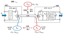
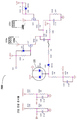
도 1 은 일부 실시형태들에 따른, 멀티-코일 송신기에 대한 코일 전류 감지를 관여하도록 구성되는 예시적인 무선 전력 송신 시스템 (100) 을 예시한다. 도 1 에 예시된 바와 같이, 전력 송신기 (TX) (102) 는 TX (102) 를 구동하기 위한 전력을 제공하는 전력 공급부 (112) 에 커플링된다. Tx (102) 의 제어기 (107) 는 하나 이상의 송신기 코일들 (106a, 106b) 을 통해 교류 전류 (AC) 를 생성하도록 구성되며, 그 송신기 코일들의 각각은 시변 자기 필드를 생성한다. 송신기 코일들 (106a 및 106b) (본 명세서에서는 총괄하여 송신기 코일 (106) 로서 지칭됨) 에 의해 생성된 시변 자기 필드들의 각각은, 각각, 수신기 코일 (108a 및 108b) 에서 개별 전류를 유도한다. 수신기 코일 (108a 또는 108b) (본 명세서에서는 총괄하여 수신기 코일 (108) 로서 지칭됨) 은, 각각, 개별 전력 수신기 (RX) (104a 또는 104b) (본 명세서에서는 총괄하여 수신기 (104) 로서 지칭됨) 에 커플링되며, 전력 수신기의 각각은 송신된 무선 전력을 수신한다. 정류기 회로 (110a 또는 110b) (본 명세서에서는 총괄하여 정류기 (110) 로서 지칭됨) 는, 각각, 수신 디바이스 (104a 또는 104b) 내에서, 수신기 코일 (108a 또는 108b) 에서 수신된 무선 전력을 수신 및 정류하도록 구성되고, 그 다음, 차례로, 배터리 충전을 위한 출력 전압을 제공한다.1 illustrates an exemplary wireless
따라서, 수신기 (RX) (104a 및 104b) 의 각각은 부하 (114a 또는 114b), 예를 들어, 배터리 충전기에 커플링되며, 이 배터리 충전기는 수신된 전력으로 배터리를 충전하도록 구성된다. 이러한 방식으로, 부하 (114a 및 114b) 는 Tx (102) 로부터 전송된 무선 전력으로 동시에 충전될 수 있다. 또는 대안적으로, 다중의 송신기 코일들 (106a 및 106b) 로, 송신 디바이스 (102) 는 더 큰 활성 충전 영역을 가질 수도 있으며, 수신 디바이스는 충전될 충전 영역 상에 더 자유롭게 배치될 수 있다.Thus, each of the receivers (RX) 104a and 104b is coupled to a
일 실시형태에 있어서, Tx 제어기 (107) 는 단일 IC 칩 상에 구축될 수 있다. Tx (102) 가 1 초과의 디바이스를 한번에 충전하기 위해, 제어기 (107) 는 안전한 고전력 무선 전송을 위해 적어도 20W 까지의 인증의 고전력 전송을 제공하도록 구성된다. 부가적으로, 1 초과의 수신 디바이스 (104a 및 104b) 가 Tx (102) 부근에 배치될 때, 제어기 (107) 는 다중의 수신 디바이스들에 대한 증가된 XY 배치 능력 및 코일 전류 감지를 통해 이물질 검출 (FOD) 을 제공하도록 구성된다. In one embodiment,
도 1 에 추가로 예시되는 바와 같이, 이물질 (124) 이 송신기 코일 (106a-b) 또는 수신기 코일 (108a-b) 부근에 배치될 경우, 이물질 (124) 은 송신 디바이스 (102) 와 수신 디바이스(들) (104a-b) 사이의 전력의 송신을 방해할 수 있다. 예를 들어, 도 2a 는 일 실시형태에 따른, 도 1 에 도시된 무선 전력 전송 시스템 (100) 의 전력 손실에 대한 이물질의 영향을 예시한 예시적인 다이어그램을 제공한다. 실시형태들에 따르면, 송신 디바이스 (102) 는, 금속 물체 (124) 가 무선 전력 전송 동안 송신기 코일 부근에 배치될 경우, 송신기 코일로부터의 송신된 전력 (PPT) 과 수신기 코일에서 수신되는 수신된 전력 (PPR) 사이의 차이로서 계산되는 전력 손실 (PLOSS) 을 구한다. PLOSS 가 크면, 이물질 문제가 존재한다.As further illustrated in FIG. 1, when a
전송 동안 전력 손실 (PLOSS) 을 계산하기 위해, 송신 디바이스 (102) 는 입력 전력 (PIN) 및 송신기 전력 손실 (PPTLoss) 을 계산하고, 수신 디바이스 (104) 는, 예컨대, 수신된 전력 패킷 (RPP) (135) 을 송신 디바이스 (102) 로 전송함으로써, 수신된 전력 (PPR) 을 송신 디바이스 (102) 에게 통지한다. 구체적으로, 무선 전력 컨소시엄 (WPC) 표준 하의 기존 시스템들은 일반적으로, 다음에 의해 송신 디바이스 (102) 로부터 출력된 전력 (PPT) 을 산출한다:To calculate the power loss (P LOSS ) during transmission, the transmitting
PPT = Vin (또는 VBRG) × Iin - PPTLoss P PT = Vin (or VBRG) × Iin-P PTLoss
여기서, Vin, Iin 은, 각각, 송신 디바이스 (102) 에서의 입력 전압 (VBRG 는 Tx 자기 필드를 생성하기 위해 Tx DC-AC 인버터에 인가된 브리지 전압임) 및 입력 전류를 나타내고, TXLOSSES 는 송신 디바이스 (102) 내에서의 전력 손실, 예컨대, Tx 자기 필드를 생성하는데 필요한 전기 컴포넌트들 및 송신기 코일에서 소비된 전력을 나타낸다. 한편, 수신 디바이스 (104) 에서, PPR, 즉, 수신 디바이스 (104) 에서 수신된 전력은 다음에 의해 계산된다:Here, Vin, Iin, respectively, represent the input voltage at the transmitting device 102 (VBRG is the bridge voltage applied to the Tx DC-AC inverter to generate the Tx magnetic field) and the input current, TX LOSSES Denotes power dissipation within the transmitting
PPR = Vrect × Iout + PPRLoss P PR = Vrect × Iout + P PRLoss
여기서, Vrect 는 수신 디바이스들 (104) 에서의 정류기 회로 (110) 에서의 전압을 나타내고, Iout 은 수신 디바이스 (104) 로부터의 출력 충전 전류를 나타내고, PPRLoss 는 수신 디바이스 (104) 내의 전력 손실을 나타낸다. 그 다음, PPR 는 RPP (135) 를 통해 송신 디바이스 (102) 에 통신된다. 따라서, FOD 전력 손실에 대한 종래의 WPC 계산을 채용하기 위해, 평균 입력 전류 (Iin) 및 평균 입력 전압 (Vin) 이 측정되고, 그 다음, TxLOSSES 가 예컨대 외삽을 통해 계산된다.Here, Vrect represents the voltage at the
하지만, 송신기 전력 손실들의 외삽은 직접 측정만큼 좋지는 않다. 집적 회로들 (IC들) 은 송신기 코일 전류를 직접 측정하도록 설계될 수 있다. Tx 코일 전압에 대한 위상 및 측정된 송신기 코일 전류 (RMS 또는 피크 전류) 는 송신기 코일 손실들의 표시자를 제공하며, 이는 일반적으로, 송신 디바이스 (102) 에서의 전력 손실의 주요 소스이다. 송신기 코일 전류 측정의 이러한 개념을 기존의 IC들에 리트로피팅 (retrofit) 하는 것은 난제이고 고가일 수 있다.However, extrapolation of transmitter power losses is not as good as direct measurement. Integrated circuits (ICs) can be designed to directly measure the transmitter coil current. The phase and measured transmitter coil current (RMS or peak current) for the Tx coil voltage provides an indicator of transmitter coil losses, which are generally the primary source of power loss at the transmitting
도 2b 및 도 2c 는 본 명세서에서 설명된 일부 실시형태들에 따른, 전력 손실 및 코일 전류에 대한 송신 디바이스 (102) 와 수신 디바이스 (104) 사이의 정렬의 영향들을 예시한 예시적인 데이터 다이어그램들을 제공한다. 송신기 코일 전류는 (수신 디바이스 (104) 의) 수신기 코일 (108) 의 포지션으로 변할 수 있다. 예를 들어, 데이터 다이어그램들 (202) 에 도시된 바와 같이, (송신기 코일 전류 (PTx_coil_IRMS) 에 의해 반영된) 송신기 전력 손실은 수신 디바이스의 XY 포지션이 변하는 동안, 예컨대, 수신 디바이스가 송신기 충전 패드의 XY 평면 상에서 이동할 때, 4배까지 변할 수도 있다. 데이터 다이어그램 (204) 에 도시된 바와 같이, 송신기 코일 전류는, 송신기 코일의 Z 포지션 (예컨대, 충전 패널에 수직인 방향) 이 수신기 코일에 대해 변하는 동안 2.6A 로부터 5A 에 가깝게 변할 수도 있다.2B and 2C provide example data diagrams illustrating the effects of alignment between transmitting
본 명세서에서 설명된 실시형태들은 아날로그-디지털 변환기들 (ADC들) 을 갖는 IC들에 코일 전류 감지 회로를 제공한다. 코일 감지 회로 (125a-b) 는 코일들 (106a-b) 의 코일 전류를 측정하기 위해 송신 디바이스 (102) 에 내부적으로 배치될 수도 있다. 또는 대안적으로, 코일 감지 회로 (125a-b) 는 송신 디바이스 (102) 의 IC 외부에 배치될 수도 있고, 코일들 (106a-b) 에 통신가능하게 커플링된다. 구체적으로, 코일 전류 감지 회로는 코일에서의 피크 코일 전류 값 및 공진 주파수를 측정하도록 구성된다. 그 다음, 제어기 (107) 는 송신기 코일 (106a-b) 에서의 전력 손실 계산을 위해 코일 전류의 평균 제곱근을 계산한다. 이러한 방식으로, (송신기 입력 전류에 기초한 종래의 산출 대신) 코일 전류에 기초하여 직접 산출된 송신기 전력 손실은 전력 손실에서의 변화의 개선된 정밀도를 제공할 수 있다. 따라서, 산출된 전력 손실은 무선 전력 전송 동안 송신기 코일 근처의 이물질을 더 정확하게 검출하기 위해 사용될 수 있다. 전력 손실 산출의 강화된 정밀도는 FOD 에 대한 코일들의 XY 포지션의 영향을 제거하거나 감소시키고, 따라서, 충전 배치의 강화된 XY 자유도를 제공한다.Embodiments described herein provide a coil current sensing circuit for ICs with analog-to-digital converters (ADCs). The
도 3 은 본 명세서에서 설명된 실시형태들에 따른, (도 1 의 125a-b 와 유사한) 코일 전류 감지 회로에 대한 예시적인 개략 회로 다이어그램 (300) 을 제공한다. 일 실시형태에 있어서, 코일 감지 회로는 송신기 코일 (106) 에 커플링되고, 이 송신기 코일은 공진 커패시터들 (144) (도시 안됨) 에 추가로 커플링된다. 코일 감지 회로는 인덕터 교류 전류 저항 (ACR), MOSFET 드레인-소스 온 저항 (RDSON), 즉, MOSFET 의 드레인과 소스 사이의 총 저항, 센서 저항 등과 같은 측정치들을 획득하고, 그 다음, 인덕터 코일, MOSFET, 센서 등에 걸친 전압들을 측정하여, Tx 코일 (106) 을 통과하는 코일 전류를 모니터링한다.3 provides an exemplary schematic circuit diagram 300 for a coil current sensing circuit (similar to 125a-b of FIG. 1 ), according to embodiments described herein. In one embodiment, the coil sensing circuit is coupled to the
일 실시형태에 있어서, 송신기 코일 (106) 에 대한 인덕터 전류 감지가 인덕터 전류 감지: L/ACR = R ![]()
![]()
일 실시형태에 있어서, 하측 MOSFET RDSON 이 측정될 수 있거나, 또는 (추가적인 컴포넌트 비용 및 전력 손실을 추가할 수도 있는) 감지 저항기가, 예컨대, (다이어그램 (300) 에서의 원 (148) 에서 도시된 바와 같은) 하측 MOSFET (Q6) 에 걸친 (노드 (147) 에서의) 전압 나누기 MOSFET RDSON, 또는 감지 저항기에 걸친 전압 나누기 감지 저항을 측정함으로써, 코일 전류를 측정하는데 사용될 수 있다. (도 4 에서의 127 에 도시된) OPAMP 가 이들 측정치들을 돕는데 사용될 수도 있는데, 왜냐하면 그러한 측정치들은 ACR 감지보다 4배 낮을 수 있기 때문이다.In one embodiment, the lower MOSFET RDSON can be measured, or a sense resistor (which may add additional component cost and power loss), for example, as shown in
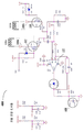
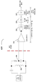
도 4a 는 본 명세서에서 설명된 실시형태들에 따른, 멀티-코일 송신기에서 모니터링하기 위한 코일을 선택하는 자동 선택 회로에 대한 예시적인 개략 회로 다이어그램 (400) 을 제공한다. 송신기가 1 초과의 코일들, 예컨대, 도 1 에 도시된 송신기 코일들 (106a-b) 을 가질 경우, MOSFET들 (117 및 118) 은 어느 코일이 측정되어야 하는지를 제어하는데 사용된다. 예를 들어, MOSFET들 (117 및 118) 은, 각각, 송신기 코일들 (106a 또는 106b) 에 각각 커플링되고, 어느 코일이 모니터링되고 있는지를 자동으로 선택하기 위해 MOSFET (117 또는 118) 을 턴온하거나 턴오프하는 전용 게이트 신호에 각각 연결된다. 따라서, MOSFET (117 또는 118) 은 오직 개별 게이트 신호가 포지티브이고 개별 코일 (106a 또는 106b) 이 에너자이징될 경우에만 활성 경로가 된다. MOSFET (117 또는 118) 이 활성일 경우, 노드 (i_AC1 또는 i_AC2) 에서의 전압은, 예컨대, MOSFET (117 또는 118) 의 MOSFET RDSON 을 나눔으로써, MOSFET (117 또는 118) 에 결합된 개별 코일의 전류를 표시하기 위해 각각 측정된다.4A provides an exemplary schematic circuit diagram 400 for an automatic selection circuit for selecting a coil for monitoring in a multi-coil transmitter, according to embodiments described herein. If the transmitter has more than one coils, eg,
일부 실시형태들에 있어서, (예컨대, 도 3 에 도시된 c170 및 R215 와 유사한) 병렬 RC 회로는, MOSFET (117 또는 118) 이 병렬 RC 감지를 통해 노드 (146a 또는 146b) 에서 전압을 샘플링할 수도 있도록 송신기 코일 (106a 또는 106b) 에 병렬로 배치된다. 병렬 RC 회로의 샘플링된 전압은, 각각, Tx 코일 (106a 또는 106b) 을 통과하는 코일 전류를 나타낸다.In some embodiments, a parallel RC circuit (eg, similar to c170 and R215 shown in FIG. 3) may allow
예시적인 목적으로, 다이어그램 (400) 은 측정될 코일을 자동으로 선택하기 위한 2개의 코일들 (106a-b) 및 2개의 MOSFET들 (117-118) 을 도시한다. 다중의 코일들 (예컨대, 2개 초과) 이 송신기에서 사용될 수 있다. 각각의 송신기 코일 (예컨대, 2개 초과) 은 개별 코일에 대한 전류 감지 회로를 갖는 샘플링 MOSFET 에 커플링되어, 샘플링 MOSFET 이, 개별 송신기 코일을 통과하는 코일 전류를 나타내는 전류 감지 회로에서의 전압을 샘플링하는데 사용될 수도 있다.For illustrative purposes, diagram 400 shows two
다이어그램 (400) 은, 아날로그 전류 또는 전압을 프로세서 (예컨대, 도 1 에서의 제어기 (107)) 에 대한 디지털 측정치로 변환하는 아날로그-디지털 변환기 (ADC) 로 공급하기 전에 코일 (106a 또는 106b) 로부터의 신호를 증폭하기 위한 OPAMP (127) 를 더 포함한다. 이러한 방식으로, OPAMP (127) 는 개선된 신호 대 노이즈 비 (SNR) 및 신호의 추가 버퍼링을 제공한다.Diagram 400 is supplied from
다이어그램 (400) 은 OPAMP (127) 의 출력에 커플링된 131 에서의 다이오드 (D30) 를 더 도시하며, 이는 피크 전압을 검출하기 위한 피크 검출기의 부분으로서 서빙할 수도 있다. 일부 예들에 있어서, 다이오드 (D30) 는, 다이오드 (D30) 에서의 입력 전압이 C229 에서의 전압보다 높을 경우 포지티브 "하프 사이클" 에서 다이오드 (D30) 에 대한 입력 전압의 피크까지 (132 에서의) 커패시터 (C229) 를 충전한다. 다이오드 (D30) 에서의 입력 전압이 커패시터 (C229) 상에 저장된 "피크" 전압 아래로 떨어질 경우, 다이오드 (D30) 는 역 바이어싱되어, 커패시터 (C229) 로부터 다시 다이오드 (D30) 의 입력단으로의 전류 흐름을 차단한다. 커패시터 (C229) 는, 다이오드 (D30) 에 대한 입력 전압이 0 으로 드롭될 때라도 피크 전압 값을 유지한다. 따라서, 피크 코일 전류 (ICOIL_Peak) 는 다이오드 (D30) 및 커패시터 (C229) 에 의해 유지된 피크 전압을 측정함으로써 측정될 수 있다.Diagram 400 further shows diode D30 at 131 coupled to the output of
공진 주파수 (F_Resonant) 는 또한, 피크 전류 (ICOIL_PEAK) 를 코일 전류의 평균 제곱근 (ICOIL_RMS) 으로 변환하기 위해 (예컨대, Q 측정 기법들을 통해) 측정된다. 그 다음, ICOIL_RMS 가 코일 전력 손실을 계산하기 위해 사용된다. 예를 들어, ICOIL_RMS 는 다음의 수학식을 통해 산출될 수도 있다:The resonant frequency (F_Resonant) is also measured (eg, via Q measurement techniques) to convert the peak current (ICOIL_PEAK) to the mean square root of the coil current (ICOIL_RMS). Then, ICOIL_RMS is used to calculate the coil power loss. For example, ICOIL_RMS may be calculated using the following equation:
ICOIL_RMS = a ×ICOIL_ADC2 - b×ICOIL_ADC + cICOIL_RMS = a ×ICOIL_ADC 2 -b×ICOIL_ADC + c
여기서, ICOIL_ADC 는 아날로그-디지털 변환기 (ADC) 로 공급된 피크 전류를 나타내며, 파라미터들 (a, b 및 c) 은 피크 검출기 전압의 데이터 샘플들을 ADC 및 송신기 코일 RMS 전류로 회귀함으로써 구할 수 있다. 예를 들어, 도 6a 는 ADC 에 대한 피크 검출기 전압에 기초하여 송신기 코일 RMS 전류를 계산하기 위한 커브 피팅 방정식을 도시하는 예시적인 데이터 플롯 (600) 을 제공한다. 이 예에 있어서, ICOIL_RMS 는 다음과 같이 계산될 수도 있다: 206.45x2 - 8.1418x + 0.9689, 여기서, x 는 ADC 에 대한 피크 검출기 전압을 나타낸다. 대안적으로, 도 6b 에 도시된 바와 같은 회로 (610) 는, 감지된 코일 전류를 RMS 값으로 변환하는데 사용될 수도 있다.Here, ICOIL_ADC represents the peak current supplied to the analog-to-digital converter (ADC), and parameters (a, b, and c) can be obtained by returning data samples of the peak detector voltage to the ADC and transmitter coil RMS currents. For example, FIG. 6A provides an
일부 실시형태들에 있어서, 송신기 코일 (106) 을 통과하는 전류가 교류 전류이므로, 피크 코일 전류 (및 결과적인 ICOIL_RMS) 는 스위칭 네트워크의 각각의 하프 브리지를 통해 검출될 수도 있다. 예를 들어, 제 1 피크 코일 전류가 스위칭 네트워크의 제 1 하프 브리지가 온될 경우 감지될 수 있고 (및 제 1 ICOIL_RMS 가 이에 따라 산출됨), 제 2 피크 코일 전류가 스위칭 네트워크의 다른 하프 브리지가 온될 경우 감지될 수 있다 (및 제 2 ICOIL_RMS 가 이에 따라 산출됨). 그 다음, 코일 전류의 RMS 는 제 1 ICOIL_RMS 및 제 2 ICOIL_RMS 의 평균으로서 산출될 수 있다. 일부 실시형태들에 있어서, 스위칭 네트워크가 데드 타임 (예컨대, 코일 전류가 최저 네거티브로부터 최고 포지티브로 천이하기 위한 시간) 으로 인해 각각의 하프 브리지에 대해 50% 시간을 온으로 갖지 않을 수도 있을 경우, 제 1 ICOIL_RMS 및 제 2 ICOIL_RMS 의 가중 평균은, 코일 전류가, 각각, 네거티브 또는 포지티브 피크에 있는 시간의 부분을 반영하는 가중치들로 구현될 수도 있다.In some embodiments, since the current passing through the
일부 실시형태들에 있어서, 데드 타임은, 2019년 4월 1일자로 출원되고 본 명세서에 참조로 전부 명백히 통합되는 미국출원 제 16/371,887 호에 추가로 기술된 바와 같이, 수신기 회로로부터의 피드백에 기초하여 무선 송신기를 교정함으로써 조정될 수도 있다.In some embodiments, the dead time is based on feedback from the receiver circuit, as further described in U.S. Application No. 16/371,887, filed April 1, 2019 and is fully incorporated herein by reference. It may be adjusted by calibrating the wireless transmitter based.
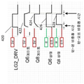
도 4b 는 본 명세서에서 설명된 실시형태들에 따른, 멀티-코일 송신기에서 MOSFET 샘플링을 통해 전류 감지를 위한 코일을 선택하는 선택 회로를 추가로 예시한 예시적인 개략 회로 다이어그램을 제공한다. 구체적으로, 각각의 송신기 코일 (106a 또는 106b) 은 고유한 구동기 전압 (LG1_DRV) (411) 또는 (LG2_DRV) (412) 에 의해 구동된다. 예를 들어, LG2_DRV (412) 가 온일 경우, 샘플링 MOSFET 저항기 (Q8) 가 설정된다. 도 4c 에 도시된 바와 같이, 파형 (426) 은, (파형 (420) 에서의) LG2_DRV 가 턴온한 이후에 Q6 이 턴온하고, 턴-온 비중첩 시간 이후에 (파형 (422) 에서 도시된) Q6 의 게이트 전압이 5V 까지 상승하는 것을 나타낸다. 따라서, 샘플링 MOSFET (Q8) 은 (파형 (428) 에서 도시된) 턴-온 비중첩 시간 이후에 턴온된다. 턴-온 비중첩 시간은 샘플링 MOSFET 게이트 구동 저항기에 기인하고, 이는 샘플링된 노드가 접지에 있음을 확인한다. 그 다음, 그 턴오프를 둔화시키는 파워 MOSFET 게이트 저항기 및 게이트 구동 저항기의 다이오드 단락으로 인해 LG2_DRV 가 턴오프하기 전에 샘플링 MOSFET (Q8) 이 턴오프한다. 이러한 방식으로, 샘플링 MOSFET (Q8) 은, 공통 LX 노드가 하이로 비행하기 시작하기 전에 오프되고, 따라서, 전류 신호는 샘플링 MOSFET (Q8) 에 의해 깨끗하게 샘플링되어, LX 노드 상의 스위칭 노이즈를 회피한다.4B provides an exemplary schematic circuit diagram further illustrating a selection circuit for selecting a coil for current sensing through MOSFET sampling in a multi-coil transmitter, in accordance with embodiments described herein. Specifically, each
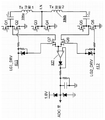
도 5 는 본 명세서에서 설명된 실시형태들에 따른, 도 4 의 것과 유사하지만 ADC 측정을 위한 다이오드 방법을 갖는 멀티-코일 송신기를 도시한 예시적인 개략 회로 다이어그램 (500) 을 제공한다. 반대 방향들로 병렬로 연결된 2개의 다이오드들로 이루어진 다이오드 리미터 (133) 는, 신호가 ADC 로 전송되기 전에 전압 또는 전류 신호를 조절하는데 사용된다.5 provides an exemplary schematic circuit diagram 500 showing a multi-coil transmitter similar to that of FIG. 4 but with a diode method for ADC measurement, according to embodiments described herein. A
도 6a 는 ADC 에 대한 피크 검출기 전압에 기초하여 송신기 코일 RMS 전류를 계산하기 위한 커브 피팅 방정식을 도시한 예시적인 데이터 플롯 (600) 을 제공한다.6A provides an
도 6b 는 감지된 코일 전류를 코일 전류 RMS 값으로 변환하는 회로 구현을 예시한 예시적인 개략 회로 다이어그램을 제공한다. 구체적으로, 교류 전류에 대해, 코일 전류의 RMS 값은, 코일에서 동일한 평균 전력 소실을 생성할 직류 전류의 값과 동일하다. 따라서, 코일 전류 RMS 값은 코일 전력 손실을 산출하는데 사용된다. (예컨대, 도 3 과 관련하여 논의된 바와 같이) 146 에서의 전압 레벨을 샘플링함으로써 감지된 코일 전류는 코일 전류 RMS 값으로 변환하기 위한 회로부 (610) 로 전송된다. 구체적으로, 회로부 (610) 는 입력 전압 신호를 증폭하도록 구성된 버퍼 또는 증폭기 (216) 를 포함한다. 그 다음, 증폭된 전압 신호는, 증폭된 전압 신호의 제곱 값을 산출하도록 승산기로 전송된다. 예를 들어, 승산기 (220) 는, 그 입력단들 양자 모두에서 증폭된 전압 신호를 수신하고 2개의 입력 신호들의 곱, 즉, 증폭된 전압 신호의 제곱에 비례하는 출력 신호를 생성하는 길버트 승산기일 수도 있다. 그 다음, 승산기 출력 신호는 평균 필터 (225) 로 전송되며, 이 평균 필터는 입력의 다수의 샘플들, 예컨대, 증폭기 전압 신호의 제곱을 한번에 취하고, 입력 샘플들의 평균을 취하여 평균화 출력 신호를 생성하도록 구성된다. 그 다음, 생성된 평균화 출력 신호는, 평균화 출력 신호의 제곱근을 산출하도록 구성된 제곱근 생성기 (227) 에 전달된다. 이러한 방식으로, 인스턴트 코일 전류 레벨 (피크 코일 전류 레벨일 수도 있고 아닐 수도 있음) 을 나타내는 146 에서의 감지된 전압 레벨이 회로 (610) 에 지속적으로 공급될 경우, 코일 전류의 RMS 값이 제곱근 생성기 (227) 의 출력에서 생성될 수도 있다.6B provides an exemplary schematic circuit diagram illustrating a circuit implementation that converts sensed coil current to coil current RMS value. Specifically, for an alternating current, the RMS value of the coil current is the same as the value of the direct current that will produce the same average power dissipation in the coil. Therefore, the coil current RMS value is used to calculate the coil power loss. The coil current sensed by sampling the voltage level at 146 (eg, as discussed in connection with FIG. 3) is sent to
회로 (610) 에 있어서, 증폭기 (216), 승산기 (220) 및 평균화 필터 (225) 는, 아날로그 입력 신호, 예컨대, 146 으로부터의 샘플링된 전압 레벨 신호를 핸들링하도록 구성되는 아날로그 디바이스들일 수도 있다. 일부 실시형태들에 있어서, 교번 전압 샘플링은, 도 3 내지 도 5 와 관련하여 논의되지만 예컨대 RDSON 감지, 저항기 감지, 또는 전류 감지 트랜스포머 등으로 한정되지 않는 전류 감지 회로들 중 임의의 회로를 통해 제공될 수 있다. 제곱근 생성기 (227) 는 아날로그 출력을 생성하거나 또는 디지털 출력이 되도록 출력을 양자화할 수도 있다. 회로 (610) 에서의 아날로그 프론트 엔드를 사용하는 것은 디지털 필터링이 뒤이어지는 고가의 ADC들의 사용을 감소시킨다. 따라서, 회로 (610) 는 더 낮은 비용의 솔루션을 렌더링할 수도 있다. 부가적으로, 디바이스들 (216, 220 및 225) 의 아날로그 프론트 엔드는, 아날로그 디바이스들이 더 높은 대역폭을 산출함에 따라 정확한 데이터 측정을 제공한다. 회로 (610) 는, 프로세서가 I_Coil_PEAK (및 다른 상태 변수들) 로부터 IRMS 를 도출하기 위한 필요성을 제거할 수도 있다.In
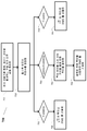
도 7a 는 본 명세서에서 설명된 실시형태들에 따른, 이물질들을 검출하기 위해 코일 전류 감지를 사용하기 위한 예시적인 프로세스 (700) 를 예시한 단순화된 로직 플로우 다이어그램을 제공한다. 단계 701 에서, 송신기 코일을 통과하는 코일 피크 전류 값이 피크 검출기를 통해 (예컨대, 피크 검출기 다이오드 (131) 를 통해) 측정된다. 코일 전류는, 도 3 내지 도 5 와 관련하여 논의된 바와 같이, 병렬 RC 회로 (예컨대, 146 참조) 에서의 전압을 MOSFET 샘플링함으로써, MOSFET RDSON 을 측정함으로써, 기타 등등에 의해 감지될 수도 있다. 그 다음, 측정된 코일 피크 전류는 송신기의 제어기 (107) 및 ADC 에 공급된다. 단계 703 에서, 제어기 (107) 는, 예컨대, 도 6 에 도시된 바와 같이, 커브 피팅 방정식에 기초하여 RMS 코일 전류를 산출한다. 단계 705 에서, 송신기 전력 손실이 RMS 코일 전류에 기초하여 산출된다, 예컨대, PPTLoss = ICOIL_RMS2 × Rcoil. 단계 707 에서, 제어기 (107) 는 송신 디바이스와 수신 디바이스 사이의 송신 전력 손실을 산출 및 모니터링하도록 구성된다. 송신기 전력 손실과 송신기 코일 근처의 이물질에 의해 야기된 전력 손실의 관계는 도 2a 와 관련하여 기술된다, 예컨대, 송신 손실 PLOSS = Vin × Iin - PPTLoss - PPR 이고, 여기서, PPR 는 RPP 통신 (135) 을 통해 획득된다. 단계 709 에서, 송신 전력 손실에서의 변화가 임계보다 큰 경우, 단계 711 에서, 제어기 (107) 는 이물질이 근처에 있음을 결정하도록 구성된다. 그렇지 않으면, 프로세스 (700) 는 단계 701 로 되돌아가며, 여기서, 송신기는 단계 701 내지 단계 707 을 통해 코일 전류를 계속 측정하고 전력 손실 변화를 모니터링한다.7A provides a simplified logic flow diagram illustrating an
도 7b 는 감지된 코일 전류를 코일 전류 RMS 값으로 변환하기 위한 도 6b 에 도시된 회로를 동작시키는 것을 예시한 예시적인 로직 플로우 다이어그램을 제공한다. 프로세스 (720) 는, 송신기 코일을 통과하는 코일 전류 값 (피크 값을 포함할 수도 있거나 포함하지 않을 수도 있음) 이 예컨대 RC 감지, MOSFET RDSON 등을 통해 전압 레벨을 샘플링함으로써 감지되는 단계 721 로 시작한다. 단계 723 에서, 코일 전류 레벨을 나타내는 감지된 전압 신호가 증폭기 (예컨대, 아날로그 증폭기 (216)) 에 전달된다. 단계 725 에서, 증폭된 신호는, 증폭된 신호의 제곱에 비례하는 출력 신호를 생성하는 승산기 (예컨대, 길버트 승산기 (220)) 로 전송된다. 단계 727 에서, 승산된 신호, 예컨대, 증폭된 신호의 제곱은 평균화 필터 (예컨대, 아날로그 평균화 필터 (225)) 에서 평균화된다. 단계 731 에서, 코일 전류의 RMS 값을 나타내는 평균화된 신호의 제곱근이 (예컨대, 제곱근 생성기 (227) 에서) 생성된다.7B provides an exemplary logic flow diagram illustrating operating the circuit shown in FIG. 6B for converting sensed coil current to coil current RMS value.
도 7c 는 본 명세서에서 설명된 실시형태들에 따른, 시스템의 동작 주파수에 기초하여 IRMS 를 산출하기 위한 예시적인 프로세스 (750) 를 예시한 단순화된 로직 플로우 다이어그램을 제공한다. 단계 751 에서, 송신기 코일을 통과하는 코일 피크 전류 값이 피크 검출기를 통해 (예컨대, 도 3 내지 도 5 에서 설명된 코일 전류 감지 회로들을 통해) 측정된다. 단계 753 에서, 시스템에 대한 펄스 폭 변조 (PWM) 의 동작 주파수가 결정된다. 예를 들어, (동작 동안 재측정될 수 있는) ~ 56 kHz 의 주어진 고유 주파수를 갖는 시스템에 대해, LRC 탱크의 자연파를 차단하는 PWM 으로 인한 동작 주파수에 의존하여 피크 전류를 IRMS 전류로 변환하기 위해 근사 팩터가 적용될 수도 있다. 단계 755 에서, PWM 주파수가 200KHz 이면, ![]()
![]()
![]()
![]()
도 3 내지 도 5 에서 설명된 코일 전류 감지 회로들은 개선된 정밀도로 계산된 송신기 전력 손실을 제공하며, 이는, 차례로, 산출된 송신 전력 손실의 정밀도를 제공한다. 송신 전력 손실에서의 개선된 정밀도로, FOD 의 정확도가 무선 전력 전송 동안 개선되어, 도 8a 및 도 8b 에서 나타낸 바와 같이, 충전 평면의 XY 활성 영역을 증가시킬 수 있다. 도 8a 에서 나타낸 바와 같이, 충전 영역은 대략 2 의 팩터만큼 증가될 수도 있는 한편, 송신기 가열 (송신기 전력 손실) 은 약 1.5 배만큼 증가할 수도 있다. 예를 들어, 도 8b 에 도시된 바와 같이, 활성 영역은, FOD 에 대한 강화된 XY 자유도로 16mm 의 직경으로부터 25mm 까지 증가할 수 있다.The coil current sensing circuits described in FIGS. 3 to 5 provide transmitter power loss calculated with improved precision, which, in turn, provides precision of the calculated transmit power loss. With improved precision in transmission power loss, the accuracy of FOD can be improved during wireless power transmission, increasing the XY active area of the charging plane, as shown in FIGS. 8A and 8B. As shown in FIG. 8A, the charging area may be increased by a factor of approximately 2, while transmitter heating (transmitter power loss) may be increased by about 1.5 times. For example, as shown in Figure 8B, the active region can increase from a diameter of 16 mm to 25 mm with enhanced XY degrees of freedom for FOD.
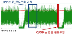
도 9a 는 급속 충전기 "상대 전류" 프로파일을 예시하는 한편, 도 9b 는 예시적인 충전 윈도우를 예시한다. 무선 전력 충전은 AP 로딩, 폰 충전 동안 디바이스 사용, 및 노이즈 프로파일로의 열 쓰로틀 가산들로 인해 노이즈가 있다. 본 명세서에서 설명된 코일 전류 감지를 사용한 FOD 는 저 노이즈에 대해 긴 윈도우를 사용한다. 특히, 다수의 측정치들이 함께 평균화되며, 이는 전력 전송에 대한 영향없이 SNR 을 크게 개선한다.9A illustrates the rapid charger “relative current” profile, while FIG. 9B illustrates an exemplary charging window. Wireless power charging is noisy due to AP loading, device use during phone charging, and thermal throttle additions to the noise profile. The FOD using coil current sensing described herein uses a long window for low noise. In particular, multiple measurements are averaged together, which significantly improves the SNR without affecting power transmission.
Q 팩터 FOD (QFOD) 에 있어서, 회로의 Q 팩터는, 예컨대, 송신기 코일 자체 공진의 감쇠율로서 시간 도메인에서, 또는 피크 주파수 대 시스템 대역폭의 비율로서 주파수 도메인에서, 측정되고 저장될 수도 있다. 측정된 Q 팩터 값은, 이물질이 검출되는지 여부를 결정하기 위해 수신 디바이스로부터 수신된 레퍼런스 Q 팩터 값과 비교될 수도 있다. 하지만, 짧은 측정 윈도우가 QFOD 에서 일반적으로 사용되며, 이는 높은 노이즈를 발생시킨다. 짧은 측정 윈도우는 오직 몇몇 데이터 포인트들 (예컨대, 10-12개 데이터 포인트들) 만을 산출하고, 이는 노이즈에 매우 민감하다. 낮은 SNR 은 결과들에 에러를 추가한다. 추가로, QFOD 를 구동하는 것은 종종, 예컨대, Q 팩터 측정을 위해 전력 전송을 중단시킬 수도 있다. 결과적으로, 본 명세서에서 설명된 코일 전류 감지를 사용한 FOD 는 QFOD 를 사용한 것보다 더 큰 성능을 산출할 수도 있다.For Q Factor FOD (QFOD), the Q factor of the circuit may be measured and stored, for example, in the time domain as the attenuation rate of the transmitter coil self resonance, or in the frequency domain as the ratio of peak frequency to system bandwidth. The measured Q factor value may be compared to a reference Q factor value received from the receiving device to determine whether a foreign object is detected. However, a short measurement window is commonly used in QFOD, which generates high noise. A short measurement window yields only a few data points (eg, 10-12 data points), which is very sensitive to noise. Low SNR adds an error to the results. Additionally, driving QFOD may often interrupt power transmission, eg, for Q factor measurement. Consequently, FOD using coil current sensing described herein may yield greater performance than using QFOD.
도 10a 내지 도 10d 는 멀티-디바이스 충전을 위한 멀티-코일 송신기들의 상이한 예들을 제공한다. 각각의 무선 전력 충전기 (1005) 는 도 1 에서의 무선 송신기 (102) 와 유사할 수 있다. 도 10b 에서의 다이어그램 (1002) 에 도시된 바와 같이, 무선 충전기 (1005) 는 2개의 디바이스들 (104a 및 104b) 에 전력 전송을 제공하도록 구성된다. 구체적으로, 단일 Tx 제어기 칩은 다중의 디바이스들 (104a 및 104b) 에 전력을 전송하기 위해 다중의 코일들을 구동하도록 구성될 수도 있다. 도 10c 에서의 다이어그램 (1003) 에 도시된 바와 같이, 무선 충전기 (1005) 에는, 각각의 충전 영역에 대해 상이한 포지션들 및/또는 배향들에 배치된 다중의 코일들 (1007) 이 장비될 수도 있다. 무선 충전기 (1005) 는 또한, 무선 전력을 전송하도록 충전 영역에 배치된 디바이스 (104a 또는 104b) 의 포지션을 식별하기 위한 XY 포지션 센서들을 포함한다. 이러한 방식으로, 무선 충전기 (1005) 는 디바이스들 (104a 또는 104b) 에 공간 자유도를 제공하고, 다양한 상이한 타입들의 디바이스들을 충전할 수 있다. 다이어그램 (1004) 에 도시된 바와 같이, 무선 충전기 (1005) 에는, 상이한 충전판들, 예컨대, XY 포지션 센서들을 갖는 충전판, 또는 패드 또는 시계와 같은 디바이스의 특정 형상을 위해 설계된 충전판 등등의 하이브리드가 장비될 수도 있다. 상이한 충전판들은 단일 Tx 제어기 칩에 의해 구동될 수 있다. 다이어그램 (1004) 은, 다른 무선 충전기 (1006) 가 유선 커넥션을 통해 또는 무선으로 무선 충전기 (1005) 에 연결될 수도 있는 실시형태를 추가로 예시하여, 인증 링크가 충전기 (1005 및 1006) 사이에 확립될 수도 있고, 이를 통해, 충전 디바이스(들) (104a-b) 가 충전 디바이스 (104c) 를 인증할 수도 있다.10A-10D provide different examples of multi-coil transmitters for multi-device charging. Each
무선 충전기 (1005) 는 도 3 내지 도 5 에 도시된 코일 감지 회로들을 포함할 수도 있고, 도 7 에서 논의된 코일 감지 방법을 채택한다. 이러한 방식으로, 무선 충전기 (1005) 는 무선 전력 전송 동안 FOD 에 대한 강화된 정밀도로 코일 전류에 기초하여 송신기 전력 손실을 산출한다. 부가적으로, 무선 충전기 (1005) 는, 예를 들어, 다이어그램들 (1003, 1004) 에 도시된 바와 같이, 무선 충전기 (1005) 의 더 큰 충전판이 다중의 코일들 (예컨대, 3개 등) 을 포함하며, 이는 더 큰 XY 포지션 자유도를 허용하여 충전 디바이스 (104a) 가 충전을 위해 상이한 포지션들 (예컨대, 충전기 (1005) 에서의 3개의 코일들에 따른 3개의 상이한 포지션들) 에 배치될 수도 있다.The
상기 상세한 설명은 본 발명의 특정 실시형태들을 예시하기 위해 제공되고 한정하는 것으로 의도되지 않는다. 본 발명의 범위 내에서 다수의 변동들 및 수정들이 가능하다. 본 발명은 다음의 청구항들에 기재된다.The above detailed description is provided and is not intended to limit the specific embodiments of the present invention. Numerous variations and modifications are possible within the scope of the invention. The invention is described in the following claims.
Claims (17)
제 1 송신기 코일;
상기 제 1 송신기 코일에 커플링된 코일 전류 감지 회로; 및
제어기를 포함하고,
상기 제어기는,
상기 코일 전류 감지 회로를 통해, 제 1 송신기 코일을 통과하는 제 1 코일 전류에 대응하는 코일 전류 값을 결정하고;
상기 코일 전류 값에 기초하여 송신기 전력 손실을 산출하고;
상기 무선 전력 송신 디바이스로부터 무선 전력 수신 디바이스로의 무선 전력 전송 동안, 산출된 상기 송신기 전력 손실에서의 변화가 임계 조건을 충족시킬 경우 상기 제 1 송신기 코일 부근의 이물질의 존재를 결정하도록
구성되는, 이물질 검출을 위한 무선 전력 송신 디바이스.A wireless power transmission device for foreign matter detection based on coil current sensing,
A first transmitter coil;
A coil current sensing circuit coupled to the first transmitter coil; And
Including a controller,
The controller,
Determining a coil current value corresponding to the first coil current passing through the first transmitter coil through the coil current sensing circuit;
Calculate transmitter power loss based on the coil current value;
During wireless power transmission from the wireless power transmitting device to the wireless power receiving device, if the calculated change in transmitter power loss satisfies a threshold condition, determine the presence of foreign matter near the first transmitter coil.
A wireless power transmission device configured to detect foreign matter.
상기 코일 전류 감지 회로는,
상기 제 1 송신기 코일을 통과하는 코일 피크 전류 값을 검출하도록 구성된 피크 검출기를 포함하고,
상기 제어기는 추가로, 상기 제 1 코일 전류의 평균 제곱근 값과 측정된 상기 코일 피크 전류 값 사이의 커브 관계 및 측정된 상기 코일 피크 전류 값에 기초하여 상기 제 1 코일 전류의 상기 평균 제곱근 값을 산출함으로써 상기 코일 전류 값을 산출하도록 구성되는, 이물질 검출을 위한 무선 전력 송신 디바이스.According to claim 1,
The coil current sensing circuit,
A peak detector configured to detect a coil peak current value passing through the first transmitter coil,
The controller further calculates the average square root value of the first coil current based on the curve relationship between the average square root value of the first coil current and the measured coil peak current value and the measured coil peak current value. And a wireless power transmission device for detecting foreign matter.
상기 제 1 코일 전류의 상기 평균 제곱근 값과 측정된 상기 코일 피크 전류 값 사이의 상기 커브 관계는 코일 전류의 평균 제곱근 값들 및 상기 코일 전류의 피크 값들의 이전에 획득된 데이터 샘플들에 기초하여 다항식 회귀에 의해 획득되는, 이물질 검출을 위한 무선 전력 송신 디바이스.According to claim 2,
The curve relationship between the mean square root value of the first coil current and the measured coil peak current value is a polynomial regression based on previously obtained data samples of the mean square root values of the coil current and the peak values of the coil current. It is obtained by, a wireless power transmission device for foreign matter detection.
상기 코일 전류 감지 회로는 추가로,
상기 제 1 송신기 코일에 걸친 전압을 측정하도록 구성되고,
상기 제어기는, 측정된 상기 전압을 상기 제 1 송신기 코일의 인덕터 교류 전류 저항에 의해 나눔으로써 상기 코일 피크 전류 값을 결정하도록 구성되는, 이물질 검출을 위한 무선 전력 송신 디바이스.According to claim 2,
The coil current sensing circuit is additionally,
Configured to measure the voltage across the first transmitter coil,
And wherein the controller is configured to determine the coil peak current value by dividing the measured voltage by the inductor alternating current resistance of the first transmitter coil.
상기 코일 전류 감지 회로는 추가로, 상기 무선 전력 송신 디바이스에서의 스위칭 회로에서 MOSFET 에 걸친 전압을 측정하도록 구성되고;
상기 제어기는 추가로, 측정된 상기 전압을 상기 MOSFET 의 드레인과 소스 사이의 저항에 의해 나눔으로써 상기 코일 피크 전류 값을 결정하도록 구성되는, 이물질 검출을 위한 무선 전력 송신 디바이스.According to claim 2,
The coil current sensing circuit is further configured to measure the voltage across the MOSFET in the switching circuit in the wireless power transmission device;
And the controller is further configured to determine the coil peak current value by dividing the measured voltage by a resistance between the drain and the source of the MOSFET.
상기 코일 전류 감지 회로는 상기 제 1 송신기 코일에 커플링된 감지 저항기에 걸친 전압을 측정하도록 구성되고;
상기 제어기는 추가로, 측정된 상기 전압을 상기 감지 저항기의 저항에 의해 나눔으로써 상기 코일 피크 전류 값을 결정하도록 구성되는, 이물질 검출을 위한 무선 전력 송신 디바이스.According to claim 2,
The coil current sensing circuit is configured to measure a voltage across a sense resistor coupled to the first transmitter coil;
And the controller is further configured to determine the coil peak current value by dividing the measured voltage by the resistance of the sense resistor.
코일 전류 레벨을 나타내는 신호를 증폭하도록 구성된 연산 증폭기를 더 포함하고;
상기 피크 검출기는,
증가된 신호 노이즈 비를 갖는 증폭된 상기 신호를 검출하고, 그리고
증폭된 상기 신호를 아날로그-디지털 변환기로 전송하도록
구성되는, 이물질 검출을 위한 무선 전력 송신 디바이스.According to claim 2,
And an operational amplifier configured to amplify the signal indicative of the coil current level;
The peak detector,
Detecting the amplified signal with an increased signal noise ratio, and
To transmit the amplified signal to an analog-to-digital converter
A wireless power transmission device configured to detect foreign matter.
상기 코일 전류 감지 회로는 추가로,
상기 코일 전류 감지 회로에서의 직류 전류 블록 커패시터를 사용함으로써 상기 피크 검출기에 의해 측정될 전압을 유지하도록 구성되는, 이물질 검출을 위한 무선 전력 송신 디바이스.According to claim 2,
The coil current sensing circuit is additionally,
A wireless power transmission device for foreign matter detection, configured to maintain a voltage to be measured by the peak detector by using a direct current block capacitor in the coil current sensing circuit.
제 2 송신기 코일; 및
상기 제 1 송신기 코일 또는 상기 제 2 송신기 코일이 에너자이징되는지 여부에 의존하여 상기 제 1 송신기 코일 또는 상기 제 2 송신기 코일의 코일 전류를 모니터링하기 위해 선택하도록 구성된 선택 회로를 더 포함하는, 이물질 검출을 위한 무선 전력 송신 디바이스.According to claim 1,
A second transmitter coil; And
And a selection circuit configured to select to monitor the coil current of the first transmitter coil or the second transmitter coil depending on whether the first transmitter coil or the second transmitter coil is energized, for foreign matter detection. Wireless power transmission device.
상기 선택 회로는 상기 제 1 송신기 코일에 커플링된 제 1 트랜지스터 및 상기 제 2 송신기 코일에 커플링된 제 2 트랜지스터를 포함하고,
상기 제어기는,
상기 제 1 송신기 코일이 에너자이징될 경우 상기 코일 전류를 통과하도록 상기 제 1 송신기 코일에 커플링된 제 1 트랜지스터를 활성화하기 위해 제 1 게이트 신호를 구성하고; 그리고
상기 제 1 트랜지스터의 드레인 및 소스에 걸친 전압을 측정하도록
구성되는, 이물질 검출을 위한 무선 전력 송신 디바이스.The method of claim 9,
The selection circuit includes a first transistor coupled to the first transmitter coil and a second transistor coupled to the second transmitter coil,
The controller,
Configure a first gate signal to activate a first transistor coupled to the first transmitter coil to pass the coil current when the first transmitter coil is energized; And
To measure the voltage across the drain and source of the first transistor
A wireless power transmission device configured to detect foreign matter.
검출된 코일 피크 전류를 상기 제 1 코일 전류의 평균 제곱근 값으로 변환하도록 구성된 변환기 회로를 더 포함하는, 이물질 검출을 위한 무선 전력 송신 디바이스.According to claim 1,
And a converter circuit configured to convert the detected coil peak current to an average square root value of the first coil current.
상기 변환기 회로는,
측정된 코일 전류를 나타내는 신호를 증폭하기 위한 증폭기;
증폭된 코일 전류를 상기 증폭된 코일 전류로 승산하여 상기 증폭된 코일 전류의 제곱을 생성하기 위한 승산기;
일 시간 기간에 걸쳐 상기 증폭된 코일 전류의 상기 제곱의 평균을 생성하기 위한 평균화 필터; 및
일 시간 기간에 걸쳐 상기 증폭된 코일 전류의 상기 제곱의 상기 평균의 제곱근을 취함으로써 코일 전류의 평균 제곱근 값을 생성하기 위한 제곱근 생성기를 포함하는, 이물질 검출을 위한 무선 전력 송신 디바이스.The method of claim 11,
The converter circuit,
An amplifier for amplifying a signal representing the measured coil current;
A multiplier for multiplying the amplified coil current by the amplified coil current to generate a square of the amplified coil current;
An averaging filter to generate an average of the squares of the amplified coil current over a period of time; And
And a square root generator for generating the mean square root value of the coil current by taking the square root of the mean of the square of the amplified coil current over an hour period.
상기 증폭기, 상기 승산기 또는 상기 평균화 필터는, 상기 증폭기, 상기 승산기 또는 상기 평균화 필터에서의 고 대역폭 프로세스를 산출하는 아날로그 디바이스인, 이물질 검출을 위한 무선 전력 송신 디바이스.The method of claim 12,
The amplifier, the multiplier or the averaging filter is an analog device that calculates a high bandwidth process in the amplifier, the multiplier or the averaging filter.
상기 제곱근 생성기는, 상기 제곱근 생성기에서의 저 대역폭 프로세스를 산출하는 디지털 또는 아날로그 디바이스인, 이물질 검출을 위한 무선 전력 송신 디바이스.The method of claim 12,
The square root generator is a digital or analog device for calculating a low bandwidth process in the square root generator, a wireless power transmission device for foreign matter detection.
측정된 코일 전류는,
펄스 폭 변조의 동작 주파수 및 고유 주파수의 입력에 기초하여 변환 팩터를 결정하는 것; 및
평균 제곱근 값을 획득하기 위해 상기 측정된 코일 전류에 상기 변환 팩터를 적용하는 것으로서, 상기 변환 팩터는 경험적 데이터로부터의 피팅 커브 또는 룩업 테이블에 기초하여 결정되는, 상기 변환 팩터를 적용하는 것
에 의해 코일 전류의 평균 제곱근 값으로 변환되는, 이물질 검출을 위한 무선 전력 송신 디바이스.The method of claim 11,
The measured coil current is
Determining a conversion factor based on the input of the operating frequency and natural frequency of pulse width modulation; And
Applying the transform factor to the measured coil current to obtain an average square root value, wherein the transform factor is determined based on a fit curve or lookup table from empirical data
Wireless power transmission device for foreign matter detection, which is converted to the mean square root value of the coil current by.
상기 변환 팩터는 상기 동작 주파수가 200KHz 인 경우 3 의 제곱근이거나, 또는 상기 변환 팩터는 상기 동작 주파수가 56KHz 인 경우 2 의 제곱근인, 이물질 검출을 위한 무선 전력 송신 디바이스.The method of claim 15,
The conversion factor is the square root of 3 when the operating frequency is 200KHz, or the conversion factor is the square root of 2 when the operating frequency is 56KHz, the wireless power transmission device for foreign matter detection.
제 1 하프 브리지가 턴온될 경우 제 1 코일 전류 값을 측정하도록 구성된 상기 제 1 하프 브리지; 및
제 2 하프 브리지가 턴온될 경우 제 2 코일 전류 값을 측정하도록 구성된 상기 제 2 하프 브리지를 더 포함하고,
상기 제어기는, 상기 제 1 코일 전류 값 또는 상기 제 2 코일 전류 값이 각각 네거티브 피크 또는 포지티브 피크에 있는 시간의 부분을 반영하는 가중치들로 상기 제 1 코일 전류 값 및 상기 제 2 코일 전류 값의 가중 평균을 산출하도록 구성되는, 이물질 검출을 위한 무선 전력 송신 디바이스.According to claim 1,
The first half bridge configured to measure a first coil current value when the first half bridge is turned on; And
And the second half bridge configured to measure the second coil current value when the second half bridge is turned on,
The controller weights the first coil current value and the second coil current value with weights that reflect a portion of the time at which the first coil current value or the second coil current value is at a negative or positive peak, respectively. A wireless power transmission device for foreign matter detection, configured to calculate an average.
Priority Applications (1)
| Application Number | Priority Date | Filing Date | Title |
|---|---|---|---|
| KR1020210152700A KR102401891B1 (en) | 2018-11-28 | 2021-11-09 | Enhanced foreign object detection with coil current sensing in wireless power transfer systems |
Applications Claiming Priority (8)
| Application Number | Priority Date | Filing Date | Title |
|---|---|---|---|
| US201862772592P | 2018-11-28 | 2018-11-28 | |
| US62/772,592 | 2018-11-28 | ||
| US201962821899P | 2019-03-21 | 2019-03-21 | |
| US62/821,899 | 2019-03-21 | ||
| US16/403,419 | 2019-05-03 | ||
| US16/403,419 US11527920B2 (en) | 2018-11-28 | 2019-05-03 | Enhanced foreign object detection with coil current sensing in wireless power transfer systems |
| US16/586,212 US11418067B2 (en) | 2018-11-28 | 2019-09-27 | Enhanced foreign object detection with coil current sensing in wireless power transfer systems |
| US16/586,212 | 2019-09-27 |
Related Child Applications (1)
| Application Number | Title | Priority Date | Filing Date |
|---|---|---|---|
| KR1020210152700A Division KR102401891B1 (en) | 2018-11-28 | 2021-11-09 | Enhanced foreign object detection with coil current sensing in wireless power transfer systems |
Publications (2)
| Publication Number | Publication Date |
|---|---|
| KR20200064934A true KR20200064934A (en) | 2020-06-08 |
| KR102326188B1 KR102326188B1 (en) | 2021-11-15 |
Family
ID=70875806
Family Applications (2)
| Application Number | Title | Priority Date | Filing Date |
|---|---|---|---|
| KR1020190154694A KR102326188B1 (en) | 2018-11-28 | 2019-11-27 | Enhanced foreign object detection with coil current sensing in wireless power transfer systems |
| KR1020210152700A KR102401891B1 (en) | 2018-11-28 | 2021-11-09 | Enhanced foreign object detection with coil current sensing in wireless power transfer systems |
Family Applications After (1)
| Application Number | Title | Priority Date | Filing Date |
|---|---|---|---|
| KR1020210152700A KR102401891B1 (en) | 2018-11-28 | 2021-11-09 | Enhanced foreign object detection with coil current sensing in wireless power transfer systems |
Country Status (3)
| Country | Link |
|---|---|
| EP (1) | EP4213342A1 (en) |
| KR (2) | KR102326188B1 (en) |
| CN (1) | CN111245107B (en) |
Cited By (3)
| Publication number | Priority date | Publication date | Assignee | Title |
|---|---|---|---|---|
| KR20220030144A (en) * | 2020-09-02 | 2022-03-10 | 한국전자기술연구원 | Detection coil of wireless power transmission system and coil structure including the same |
| WO2022050647A1 (en) * | 2020-09-02 | 2022-03-10 | 한국전자기술연구원 | Detection coil of wireless power transmission system and coil structure including same |
| US11685269B2 (en) | 2018-04-19 | 2023-06-27 | General Electric Company | Device, system and method for detection of a foreign object |
Families Citing this family (6)
| Publication number | Priority date | Publication date | Assignee | Title |
|---|---|---|---|---|
| CN113872339A (en) * | 2020-06-30 | 2021-12-31 | 深圳市海思半导体有限公司 | Wireless charging chip, wireless charger and wireless power transmission system |
| CN111736006B (en) * | 2020-08-07 | 2020-11-24 | 成都市易冲半导体有限公司 | Convenient detection method applied to wireless charging coil RMS current |
| US11175319B1 (en) * | 2020-09-18 | 2021-11-16 | Stmicroelectronics Asia Pacific Pte Ltd | High accuracy low temperature drift high-side current sensing hardware and method |
| CN113933592B (en) * | 2021-10-12 | 2023-04-04 | 无锡硅动力微电子股份有限公司 | High-precision Q value rapid detection circuit and method |
| CN114123533A (en) * | 2021-10-29 | 2022-03-01 | 伏达半导体(合肥)有限公司 | Wireless power transmission system and control method thereof |
| WO2023106778A1 (en) * | 2021-12-07 | 2023-06-15 | 삼성전자 주식회사 | Foreign object detection method and electronic apparatus |
Citations (3)
| Publication number | Priority date | Publication date | Assignee | Title |
|---|---|---|---|---|
| US20160309418A1 (en) * | 2015-04-16 | 2016-10-20 | Nxp B.V. | Method and system for performing foreign object detection in an inductive wireless power transfer system |
| KR20170018454A (en) * | 2014-06-20 | 2017-02-17 | 파워바이프록시 리미티드 | Foreign object detection in inductive power transfer field |
| KR20170122246A (en) * | 2015-03-04 | 2017-11-03 | 로무 가부시키가이샤 | Wireless transmission device, foreign object detection method, charger |
Family Cites Families (6)
| Publication number | Priority date | Publication date | Assignee | Title |
|---|---|---|---|---|
| US7071759B2 (en) * | 2003-05-07 | 2006-07-04 | Ballard Power Systems Corporation | Method for determining RMS values for grid-linked converters |
| TWI523366B (en) * | 2010-02-08 | 2016-02-21 | 通路實業集團國際公司 | Input parasitic metal detection and method and primary unit for same |
| US9391470B2 (en) * | 2013-11-06 | 2016-07-12 | Blackberry Limited | Energy transfer optimization by detecting and mitigating magnetic saturation in wireless charging with foreign object detection |
| US9369183B2 (en) * | 2014-05-15 | 2016-06-14 | Qualcomm Incorporated | Systems and methods for measuring power and impedance in wireless power charging systems |
| CN205157695U (en) * | 2015-11-27 | 2016-04-13 | 北京恒源利通电力技术有限公司 | Based on adjustable fault current sensor of low -power consumption definite value |
| EP3373414B1 (en) * | 2017-03-07 | 2019-10-23 | Powermat Technologies Ltd. | System for wireless power charging |
-
2019
- 2019-11-21 CN CN201911152699.2A patent/CN111245107B/en active Active
- 2019-11-27 KR KR1020190154694A patent/KR102326188B1/en active IP Right Grant
- 2019-11-27 EP EP23156327.1A patent/EP4213342A1/en active Pending
-
2021
- 2021-11-09 KR KR1020210152700A patent/KR102401891B1/en active IP Right Grant
Patent Citations (3)
| Publication number | Priority date | Publication date | Assignee | Title |
|---|---|---|---|---|
| KR20170018454A (en) * | 2014-06-20 | 2017-02-17 | 파워바이프록시 리미티드 | Foreign object detection in inductive power transfer field |
| KR20170122246A (en) * | 2015-03-04 | 2017-11-03 | 로무 가부시키가이샤 | Wireless transmission device, foreign object detection method, charger |
| US20160309418A1 (en) * | 2015-04-16 | 2016-10-20 | Nxp B.V. | Method and system for performing foreign object detection in an inductive wireless power transfer system |
Cited By (3)
| Publication number | Priority date | Publication date | Assignee | Title |
|---|---|---|---|---|
| US11685269B2 (en) | 2018-04-19 | 2023-06-27 | General Electric Company | Device, system and method for detection of a foreign object |
| KR20220030144A (en) * | 2020-09-02 | 2022-03-10 | 한국전자기술연구원 | Detection coil of wireless power transmission system and coil structure including the same |
| WO2022050647A1 (en) * | 2020-09-02 | 2022-03-10 | 한국전자기술연구원 | Detection coil of wireless power transmission system and coil structure including same |
Also Published As
| Publication number | Publication date |
|---|---|
| CN111245107A (en) | 2020-06-05 |
| EP4213342A1 (en) | 2023-07-19 |
| KR102401891B1 (en) | 2022-05-24 |
| CN111245107B (en) | 2024-03-19 |
| KR102326188B1 (en) | 2021-11-15 |
| KR20210136954A (en) | 2021-11-17 |
Similar Documents
| Publication | Publication Date | Title |
|---|---|---|
| KR102401891B1 (en) | Enhanced foreign object detection with coil current sensing in wireless power transfer systems | |
| US20210083522A1 (en) | Input parasitic metal detection | |
| EP3661014B1 (en) | Enhanced foreign object detection with coil current sensing in wireless power transfer systems | |
| US11527920B2 (en) | Enhanced foreign object detection with coil current sensing in wireless power transfer systems | |
| JP4741583B2 (en) | Control of inductive power transfer system | |
| US20180191200A1 (en) | Inductive power transfer | |
| JP2017521040A (en) | Foreign object detection in inductive power transmission field | |
| US9866051B2 (en) | Adaptive charger to maximize charge rate | |
| JP2013162709A (en) | Control device and radio power transmission device | |
| US20160336857A1 (en) | Switching-mode power supplies | |
| US11095160B2 (en) | Non-contact power supply device | |
| US20110194316A1 (en) | Switching power supply device | |
| US20210143676A1 (en) | Non-contact power supply device and method for abnormal stop | |
| US20130334893A1 (en) | Power transmission system and power transmitting apparatus | |
| KR20150115339A (en) | Wireless Power Transfer System | |
| JP6172014B2 (en) | Power transmission equipment and contactless power transmission device | |
| US20210376642A1 (en) | Electronic device to wirelessly receive power and operating method thereof | |
| JP7100734B1 (en) | Wireless power receiving device | |
| JP2016052172A (en) | Transmission apparatus and non-contact power transmission apparatus | |
| JP2013258878A (en) | Rectifier |
Legal Events
| Date | Code | Title | Description |
|---|---|---|---|
| E902 | Notification of reason for refusal | ||
| E701 | Decision to grant or registration of patent right | ||
| A107 | Divisional application of patent | ||
| GRNT | Written decision to grant |