KR20200063203A - Arc source with limited magnetic field - Google Patents
Arc source with limited magnetic field Download PDFInfo
- Publication number
- KR20200063203A KR20200063203A KR1020207012634A KR20207012634A KR20200063203A KR 20200063203 A KR20200063203 A KR 20200063203A KR 1020207012634 A KR1020207012634 A KR 1020207012634A KR 20207012634 A KR20207012634 A KR 20207012634A KR 20200063203 A KR20200063203 A KR 20200063203A
- Authority
- KR
- South Korea
- Prior art keywords
- target
- magnetic field
- arc
- magnetic
- generating
- Prior art date
Links
- 230000005291 magnetic effect Effects 0.000 title claims abstract description 133
- 230000006698 induction Effects 0.000 claims abstract description 25
- 239000003302 ferromagnetic material Substances 0.000 claims abstract description 22
- 230000002093 peripheral effect Effects 0.000 claims abstract description 17
- 230000000694 effects Effects 0.000 claims abstract description 6
- 238000001816 cooling Methods 0.000 claims abstract description 4
- XEEYBQQBJWHFJM-UHFFFAOYSA-N Iron Chemical compound [Fe] XEEYBQQBJWHFJM-UHFFFAOYSA-N 0.000 claims description 26
- 229910052742 iron Inorganic materials 0.000 claims description 13
- 229910000746 Structural steel Inorganic materials 0.000 claims description 4
- 238000001704 evaporation Methods 0.000 claims description 4
- 229910000734 martensite Inorganic materials 0.000 claims description 2
- 229910001220 stainless steel Inorganic materials 0.000 claims description 2
- 238000000034 method Methods 0.000 claims 10
- 239000011248 coating agent Substances 0.000 description 27
- 238000000576 coating method Methods 0.000 description 27
- 239000000463 material Substances 0.000 description 10
- 239000000696 magnetic material Substances 0.000 description 9
- 239000000758 substrate Substances 0.000 description 9
- 238000000151 deposition Methods 0.000 description 8
- 239000010406 cathode material Substances 0.000 description 7
- 230000008021 deposition Effects 0.000 description 7
- 230000001965 increasing effect Effects 0.000 description 7
- 229910001209 Low-carbon steel Inorganic materials 0.000 description 3
- 230000007797 corrosion Effects 0.000 description 3
- 238000005260 corrosion Methods 0.000 description 3
- 238000010891 electric arc Methods 0.000 description 3
- IJGRMHOSHXDMSA-UHFFFAOYSA-N Atomic nitrogen Chemical compound N#N IJGRMHOSHXDMSA-UHFFFAOYSA-N 0.000 description 2
- 229910001873 dinitrogen Inorganic materials 0.000 description 2
- 230000008020 evaporation Effects 0.000 description 2
- 230000002688 persistence Effects 0.000 description 2
- -1 S235JR or S355J2 Inorganic materials 0.000 description 1
- 230000015572 biosynthetic process Effects 0.000 description 1
- 230000007812 deficiency Effects 0.000 description 1
- 238000005516 engineering process Methods 0.000 description 1
- 230000001747 exhibiting effect Effects 0.000 description 1
- 230000005294 ferromagnetic effect Effects 0.000 description 1
- 230000004907 flux Effects 0.000 description 1
- 239000007789 gas Substances 0.000 description 1
- 230000001939 inductive effect Effects 0.000 description 1
- 150000004767 nitrides Chemical class 0.000 description 1
- 238000012856 packing Methods 0.000 description 1
- 230000035699 permeability Effects 0.000 description 1
- 239000012495 reaction gas Substances 0.000 description 1
- 238000009834 vaporization Methods 0.000 description 1
- 230000008016 vaporization Effects 0.000 description 1
Images


Classifications
-
- C—CHEMISTRY; METALLURGY
- C23—COATING METALLIC MATERIAL; COATING MATERIAL WITH METALLIC MATERIAL; CHEMICAL SURFACE TREATMENT; DIFFUSION TREATMENT OF METALLIC MATERIAL; COATING BY VACUUM EVAPORATION, BY SPUTTERING, BY ION IMPLANTATION OR BY CHEMICAL VAPOUR DEPOSITION, IN GENERAL; INHIBITING CORROSION OF METALLIC MATERIAL OR INCRUSTATION IN GENERAL
- C23C—COATING METALLIC MATERIAL; COATING MATERIAL WITH METALLIC MATERIAL; SURFACE TREATMENT OF METALLIC MATERIAL BY DIFFUSION INTO THE SURFACE, BY CHEMICAL CONVERSION OR SUBSTITUTION; COATING BY VACUUM EVAPORATION, BY SPUTTERING, BY ION IMPLANTATION OR BY CHEMICAL VAPOUR DEPOSITION, IN GENERAL
- C23C14/00—Coating by vacuum evaporation, by sputtering or by ion implantation of the coating forming material
- C23C14/22—Coating by vacuum evaporation, by sputtering or by ion implantation of the coating forming material characterised by the process of coating
- C23C14/24—Vacuum evaporation
- C23C14/32—Vacuum evaporation by explosion; by evaporation and subsequent ionisation of the vapours, e.g. ion-plating
- C23C14/325—Electric arc evaporation
-
- C—CHEMISTRY; METALLURGY
- C23—COATING METALLIC MATERIAL; COATING MATERIAL WITH METALLIC MATERIAL; CHEMICAL SURFACE TREATMENT; DIFFUSION TREATMENT OF METALLIC MATERIAL; COATING BY VACUUM EVAPORATION, BY SPUTTERING, BY ION IMPLANTATION OR BY CHEMICAL VAPOUR DEPOSITION, IN GENERAL; INHIBITING CORROSION OF METALLIC MATERIAL OR INCRUSTATION IN GENERAL
- C23C—COATING METALLIC MATERIAL; COATING MATERIAL WITH METALLIC MATERIAL; SURFACE TREATMENT OF METALLIC MATERIAL BY DIFFUSION INTO THE SURFACE, BY CHEMICAL CONVERSION OR SUBSTITUTION; COATING BY VACUUM EVAPORATION, BY SPUTTERING, BY ION IMPLANTATION OR BY CHEMICAL VAPOUR DEPOSITION, IN GENERAL
- C23C14/00—Coating by vacuum evaporation, by sputtering or by ion implantation of the coating forming material
- C23C14/06—Coating by vacuum evaporation, by sputtering or by ion implantation of the coating forming material characterised by the coating material
- C23C14/0641—Nitrides
-
- C—CHEMISTRY; METALLURGY
- C23—COATING METALLIC MATERIAL; COATING MATERIAL WITH METALLIC MATERIAL; CHEMICAL SURFACE TREATMENT; DIFFUSION TREATMENT OF METALLIC MATERIAL; COATING BY VACUUM EVAPORATION, BY SPUTTERING, BY ION IMPLANTATION OR BY CHEMICAL VAPOUR DEPOSITION, IN GENERAL; INHIBITING CORROSION OF METALLIC MATERIAL OR INCRUSTATION IN GENERAL
- C23C—COATING METALLIC MATERIAL; COATING MATERIAL WITH METALLIC MATERIAL; SURFACE TREATMENT OF METALLIC MATERIAL BY DIFFUSION INTO THE SURFACE, BY CHEMICAL CONVERSION OR SUBSTITUTION; COATING BY VACUUM EVAPORATION, BY SPUTTERING, BY ION IMPLANTATION OR BY CHEMICAL VAPOUR DEPOSITION, IN GENERAL
- C23C14/00—Coating by vacuum evaporation, by sputtering or by ion implantation of the coating forming material
- C23C14/22—Coating by vacuum evaporation, by sputtering or by ion implantation of the coating forming material characterised by the process of coating
- C23C14/24—Vacuum evaporation
- C23C14/243—Crucibles for source material
-
- C—CHEMISTRY; METALLURGY
- C23—COATING METALLIC MATERIAL; COATING MATERIAL WITH METALLIC MATERIAL; CHEMICAL SURFACE TREATMENT; DIFFUSION TREATMENT OF METALLIC MATERIAL; COATING BY VACUUM EVAPORATION, BY SPUTTERING, BY ION IMPLANTATION OR BY CHEMICAL VAPOUR DEPOSITION, IN GENERAL; INHIBITING CORROSION OF METALLIC MATERIAL OR INCRUSTATION IN GENERAL
- C23C—COATING METALLIC MATERIAL; COATING MATERIAL WITH METALLIC MATERIAL; SURFACE TREATMENT OF METALLIC MATERIAL BY DIFFUSION INTO THE SURFACE, BY CHEMICAL CONVERSION OR SUBSTITUTION; COATING BY VACUUM EVAPORATION, BY SPUTTERING, BY ION IMPLANTATION OR BY CHEMICAL VAPOUR DEPOSITION, IN GENERAL
- C23C14/00—Coating by vacuum evaporation, by sputtering or by ion implantation of the coating forming material
- C23C14/22—Coating by vacuum evaporation, by sputtering or by ion implantation of the coating forming material characterised by the process of coating
- C23C14/54—Controlling or regulating the coating process
-
- H—ELECTRICITY
- H01—ELECTRIC ELEMENTS
- H01J—ELECTRIC DISCHARGE TUBES OR DISCHARGE LAMPS
- H01J37/00—Discharge tubes with provision for introducing objects or material to be exposed to the discharge, e.g. for the purpose of examination or processing thereof
- H01J37/32—Gas-filled discharge tubes
- H01J37/32009—Arrangements for generation of plasma specially adapted for examination or treatment of objects, e.g. plasma sources
- H01J37/32055—Arc discharge
-
- H—ELECTRICITY
- H01—ELECTRIC ELEMENTS
- H01J—ELECTRIC DISCHARGE TUBES OR DISCHARGE LAMPS
- H01J37/00—Discharge tubes with provision for introducing objects or material to be exposed to the discharge, e.g. for the purpose of examination or processing thereof
- H01J37/32—Gas-filled discharge tubes
- H01J37/32431—Constructional details of the reactor
- H01J37/32532—Electrodes
- H01J37/32541—Shape
-
- H—ELECTRICITY
- H01—ELECTRIC ELEMENTS
- H01J—ELECTRIC DISCHARGE TUBES OR DISCHARGE LAMPS
- H01J37/00—Discharge tubes with provision for introducing objects or material to be exposed to the discharge, e.g. for the purpose of examination or processing thereof
- H01J37/32—Gas-filled discharge tubes
- H01J37/32431—Constructional details of the reactor
- H01J37/32532—Electrodes
- H01J37/3255—Material
-
- H—ELECTRICITY
- H01—ELECTRIC ELEMENTS
- H01J—ELECTRIC DISCHARGE TUBES OR DISCHARGE LAMPS
- H01J37/00—Discharge tubes with provision for introducing objects or material to be exposed to the discharge, e.g. for the purpose of examination or processing thereof
- H01J37/32—Gas-filled discharge tubes
- H01J37/32431—Constructional details of the reactor
- H01J37/32532—Electrodes
- H01J37/32559—Protection means, e.g. coatings
-
- H—ELECTRICITY
- H01—ELECTRIC ELEMENTS
- H01J—ELECTRIC DISCHARGE TUBES OR DISCHARGE LAMPS
- H01J37/00—Discharge tubes with provision for introducing objects or material to be exposed to the discharge, e.g. for the purpose of examination or processing thereof
- H01J37/32—Gas-filled discharge tubes
- H01J37/32431—Constructional details of the reactor
- H01J37/3266—Magnetic control means
- H01J37/32669—Particular magnets or magnet arrangements for controlling the discharge
-
- H—ELECTRICITY
- H05—ELECTRIC TECHNIQUES NOT OTHERWISE PROVIDED FOR
- H05H—PLASMA TECHNIQUE; PRODUCTION OF ACCELERATED ELECTRICALLY-CHARGED PARTICLES OR OF NEUTRONS; PRODUCTION OR ACCELERATION OF NEUTRAL MOLECULAR OR ATOMIC BEAMS
- H05H1/00—Generating plasma; Handling plasma
- H05H1/24—Generating plasma
- H05H1/48—Generating plasma using an arc
- H05H1/50—Generating plasma using an arc and using applied magnetic fields, e.g. for focusing or rotating the arc
-
- H—ELECTRICITY
- H01—ELECTRIC ELEMENTS
- H01J—ELECTRIC DISCHARGE TUBES OR DISCHARGE LAMPS
- H01J2237/00—Discharge tubes exposing object to beam, e.g. for analysis treatment, etching, imaging
- H01J2237/15—Means for deflecting or directing discharge
- H01J2237/152—Magnetic means
-
- H—ELECTRICITY
- H01—ELECTRIC ELEMENTS
- H01J—ELECTRIC DISCHARGE TUBES OR DISCHARGE LAMPS
- H01J2237/00—Discharge tubes exposing object to beam, e.g. for analysis treatment, etching, imaging
- H01J2237/32—Processing objects by plasma generation
- H01J2237/33—Processing objects by plasma generation characterised by the type of processing
- H01J2237/332—Coating
Landscapes
- Chemical & Material Sciences (AREA)
- Engineering & Computer Science (AREA)
- Physics & Mathematics (AREA)
- Plasma & Fusion (AREA)
- Analytical Chemistry (AREA)
- Materials Engineering (AREA)
- Organic Chemistry (AREA)
- Metallurgy (AREA)
- Mechanical Engineering (AREA)
- Chemical Kinetics & Catalysis (AREA)
- Spectroscopy & Molecular Physics (AREA)
- Physical Vapour Deposition (AREA)
- Plasma Technology (AREA)
- Discharge Heating (AREA)
Abstract
아크 증발기는 - 냉각 판(11), 캐소드 요소로서의 타겟(1)을 포함하는 캐소드 어셈블리, - 전극, 및 - 타켓(1)의 배면(1B) 전방에 배치되는 자기 유도 시스템을 포함하며, 전극은 전극과 타겟(1)의 전면(1A) 사이에 타겟(1)의 전면(1A)의 적어도 일부를 증발시키기 위한 아크가 형성될 수 있게 하도록 배열되고, 자기 유도 시스템은 하나 이상의 자기장을 생성하는 수단을 포함하되, 여기서 - 캐소드 어셈블리의 경계들이 강자성 재료로 만들어지는 주변 쉴드(15)를 포함하고, 주변 쉴드(15)는 가로 방향으로 전체 높이(H)를 가지며, 상기 전체 높이(H)는 임의의 길이 방향으로 연장하는 자기장 라인들의 차폐 효과를 발생시키고 이러한 방식으로 캐소드 어셈블리의 경계들을 임의의 길이 방향으로 자기장 라인들의 연장의 한계로서 확립시키는 성분(C)을 포함한다.The arc evaporator comprises a cooling plate 11, a cathode assembly comprising a target 1 as a cathode element, an electrode, and a magnetic induction system disposed in front of the back 1B of the target 1, the electrode Arrangements are made to allow an arc to evaporate at least a portion of the front surface 1A of the target 1 between the electrode and the front surface 1A of the target 1, and the magnetic induction system means for generating one or more magnetic fields. Including, wherein-the boundary of the cathode assembly includes a peripheral shield 15 made of ferromagnetic material, the peripheral shield 15 has a total height H in the transverse direction, the total height H is arbitrary It comprises a component (C) which creates a shielding effect of the magnetic field lines extending in the longitudinal direction of and establishes the boundaries of the cathode assembly in this way as a limit of the extension of the magnetic field lines in any longitudinal direction.
Description
본 발명은 한정된 자기장을 포함하는 신규의 아크 소스에 관한 것이다.The present invention relates to a novel arc source comprising a defined magnetic field.
본 발명의 아크 소스는 코팅될 기판 표면에 코팅 필름을 증착시키기 위한 코팅 물질 및 특수 차폐물을 생성하기 위하여 기화될 캐소드 물질을 포함하는데, 이로 인해 종래 기술에 속하는 공지의 아크 소스들과 비교하여 코팅 중의 효율이 상당히 증가될 수 있다.The arc source of the present invention comprises a coating material for depositing a coating film on the surface of the substrate to be coated and a cathode material to be vaporized to produce a special shield, which is under coating compared to known arc sources belonging to the prior art. Efficiency can be significantly increased.
이하 타겟이라는 용어를 기화될 캐소드 물질을 지칭하는데 사용할 것이다. Hereinafter, the term target will be used to refer to the cathode material to be vaporized.
본 발명의 맥락에서, 아크 소스라는 용어가 아크 방전 효과에 의해 기화될 캐소드 물질로 작동할 타겟을 포함하는 아크 증발기를 지칭하는 데 사용된다.In the context of the present invention, the term arc source is used to refer to an arc evaporator comprising a target that will act as a cathode material to be vaporized by the arc discharge effect.
본 발명은 아크 증발기 분야에 속하고, 구체적으로 자기장을 생성함으로써 아크 궤적을 유도하는 수단을 포함하는 아크 증발기 분야에 속한다.The present invention belongs to the field of arc evaporators, and specifically to the field of arc evaporators comprising means for inducing arc trajectories by generating a magnetic field.
아크 증발기 기계는 일반적으로, 챔버 자체 외에, 적어도 하나의 전극 및 하나의 캐소드를 포함하며, 이들 사이에서 전기 아크가 형성된다. 기화되는 캐소드 표면의 부식을 억제하고 액적 형성을 감소시킬 목적으로 아크 이동의 무작위적인 특성을 방지하거나 혹은 감소시키기 위해, 아크의 움직임을 제어하는 제어 또는 자기 유도 시스템이 개발되었다. 이러한 유도 시스템은 전기 아크의 움직임에 영향을 미치는 자기장을 형성하고 변형시킨다. 이러한 유형의 각기 다른 시스템을 설명하는 다수의 특허 공보 또는 특허 출원 공개 공보가 있다.The arc evaporator machine generally includes at least one electrode and one cathode, in addition to the chamber itself, between which an electric arc is formed. In order to prevent or reduce the random nature of arc movement with the aim of suppressing corrosion of the vaporized cathode surface and reducing droplet formation, a control or magnetic induction system has been developed to control the movement of the arc. These induction systems form and deform magnetic fields that affect the movement of the electric arc. There are a number of patent publications or patent application publications describing different systems of this type.
Goikoetxea Larrinaga는, 예를 들어, 미국 특허 출원 번호 12/097,28에서 자기 유도 시스템을 포함하는 아크 증발기를 설명한다. 이 문서에서는 자기 유도 시스템이 캐소드 아크의 제어를 가능하게 하고 캐소드 아크를 캐소드 플레이트의 넓은 영역에 걸쳐 움직이게 하기 위해 설계되는 것으로 설명한다. 보다 구체적으로, 자기 유도 시스템은 캐소드 포인트(캐소드 스팟이라고도 함)의 유도가 가능하게 해야 한다. 캐소드 포인트는 아크가 캐소드에 충격하는 지점으로 이해해야 한다. 자기 유도 시스템을 사용하는 것에 의해, 캐소드 포인트는 실질적으로 무한한 수의 가능한 경로들 중에서 개별적으로 선택된 경로에 따라 유도되어야 한다. 자기 유도 시스템은 전적으로 증발 챔버의 외부에 배치되도록 설계된다. 이러한 아크 증발기는 캐소드 요소로 사용되는 증발 타겟(직경 100mm의 원형 증발기 타겟), 지지체를 형성하도록 설계된 강자성 코어 및 자기장을 생성하기 위한 자기 장치를 포함한다. 자기 장치는 중심 극 및 주변 극뿐만 아니라 제1 자기장 생성 수단 및 제2 자기장 생성 수단을 포함하고, 이에 따라 각각의 자기장 성분이 캐소드 요소에 상응하는 전체 자기장에 기여한다.Goikoetxea Larrinaga describes, for example, an arc evaporator comprising a magnetic induction system in US Patent Application No. 12/097,28. This document describes that the magnetic induction system is designed to enable control of the cathode arc and to move the cathode arc over a large area of the cathode plate. More specifically, the magnetic induction system should enable induction of a cathode point (also called a cathode spot). The cathode point should be understood as the point at which the arc strikes the cathode. By using a magnetic induction system, the cathode point must be derived according to an individually selected path from a substantially infinite number of possible paths. The magnetic induction system is designed to be placed entirely outside the evaporation chamber. This arc evaporator includes an evaporation target used as a cathode element (a circular evaporator target having a diameter of 100 mm), a ferromagnetic core designed to form a support, and a magnetic device for generating a magnetic field. The magnetic device comprises a first magnetic field generating means and a second magnetic field generating means as well as a central pole and a peripheral pole, so that each magnetic field component contributes to the entire magnetic field corresponding to the cathode element.
현재 이용 가능한 아크 소스(즉, 아크 증발기)를 사용하면, 2개 이상의 아크 소스가 코팅 챔버 내에 서로의 옆에 배치되는 경우 아크 궤적을 유도하고 결과적으로 아크 소스의 타겟 표면에서 캐소드 스팟 경로를 제어하기 위해 생성되는 자기장이 옆에 배치된 다른 아크 소스들에 상응하는 다른 자기장들을 교란시키게 되고, 이는 서로에 대해 옆에 배치된 각기 다른 아크 소스들의 자기장들 간에 상호 교란을 초래할 수 있는 단점이 있다.Using currently available arc sources (i.e., arc evaporators), when two or more arc sources are placed next to each other in a coating chamber, they induce arc trajectories and consequently control the cathode spot path at the target surface of the arc source. The disadvantage is that the generated magnetic field disturbs other magnetic fields corresponding to other arc sources arranged next to each other, which can cause mutual disturbance between magnetic fields of different arc sources arranged next to each other.
종래 기술에 따른 아크 소스의 위에서 언급한 결함을 고려하여, 본 발명의 주된 목적은 코팅 챔버에 보다 밀접한 간격으로 배치된 아크 소스들을 구비하는 아크 소스 장치를 구현할 수 있게 하는 대안적인 구성 형태를 갖는 신규의 아크 소스를 제공하는 데 있다.In view of the above-mentioned deficiencies of the arc source according to the prior art, the main object of the present invention is a novelty with an alternative configuration that enables the implementation of an arc source device having arc sources arranged more closely spaced in the coating chamber. To provide an arc source.
위에서 언급한 목적을 달성하기 위하여, 본 발명은, 효율 향상을 위하여 보다 조밀하게 패킹된 배열 형태를 형성하도록 아크 소스들을 배치할 수 있게 하는, 특허청구범위 청구항 1에 한정된 아크 소스를 제공한다.In order to achieve the above-mentioned object, the present invention provides an arc source as defined in
구체적으로, 본 발명에 따른 아크 소스(아크 증발기)는,Specifically, the arc source (arc evaporator) according to the present invention,
- 냉각 판(11), 캐소드 요소로서의 타겟(1)을 포함하는 캐소드 어셈블리,-A cathode assembly comprising a
- 전극(도 6a 및 도 6b에는 도시되지 않음), 및-Electrodes (not shown in FIGS. 6A and 6B), and
- 타겟(1)의 배면(1B) 전방에 배치되는 자기 유도 시스템을 포함하고,-A magnetic induction system disposed in front of the
타겟은 바람직하게는 디스크형 타겟이지만 예를 들어 직사각형 타겟일 수 있고, 타겟(1)은 횡방향 두께, 증발되도록 배치되는 전면(1A) 및 배면(1B)을 구비하며, 전면(1A)은 배면(1B)과 평행하고, 이들 양 면은 타겟(1)의 두께만큼 서로 이격되어 있고, 캐소드 어셈블리는 가로 방향으로 전체 높이를 가지며 그리고 임의의 길이 방향으로 전체 폭을 획정하는 경계들을 구비하고,The target is preferably a disc-shaped target, but may be, for example, a rectangular target, and the
전극은 타겟(1)의 전면(1A)의 적어도 일부를 증발시키기 위한 아크가 전극과 타겟(1)의 전면(1A) 사이에 확립될 수 있도록 공지된 방식으로 배열되고,The electrodes are arranged in a known manner so that an arc for evaporating at least a portion of the
자기 유도 시스템은, 전극과 타겟(1)의 전면(1A) 사이에 아크가 형성될 때, 아크가 타겟(1)에 접촉함으로써 발생되는 캐소드 스팟을 유도하기 위해 타겟의 횡단면을 통과하여 그리고 타겟(1)의 전면(1A) 전방에 있는 공간을 따라 연장하는 자기장 라인들을 포함하는 전체 자기장을 발생시키는 하나 이상의 자기장을 생성하는 수단을 포함하고,The magnetic induction system, when an arc is formed between the electrode and the
여기서,here,
- 캐소드 어셈블리의 경계들이 강자성 재료로 만들어지는 주변 쉴드(15)를 포함하고, 주변 쉴드(15)는 가로 방향으로 전체 높이(H)를 가지며, 상기 전체 높이(H)는 임의의 길이 방향으로 연장하는 자기장 라인들의 차폐 효과를 발생시키고 이러한 방식으로 캐소드 어셈블리의 경계들을 임의의 길이 방향으로 자기장 라인들이 연장하는 한계로서 확립시키는 성분(C)을 포함한다.-The borders of the cathode assembly include a
주변 쉴드(15)의 전체 높이(H)의 적절한 성분(C)을 선택하기 위해, 캐소드 어셈블리의 치수가 반드시 고려되어야 한다.In order to select the appropriate component (C) of the overall height (H) of the surrounding shield (15), the dimensions of the cathode assembly must be taken into account.
예를 들어, 캐소드 어셈블리가 타겟 직경(D1)을 갖는 디스크형 타겟을 포함하는 대칭적인 구성 형태를 가지고, 그리고 캐소드 어셈블리가 도 6a에 개략적으로 도시된 예의 경우에서와 같이 전체 직경(D)을 가지는 경우, 주변 쉴드(15)의 전체 높이(H)의 성분(C)에 대한 권장 값은 D/20 ≤ C ≤ D/5의 범위에 있을 수 있다.For example, the cathode assembly has a symmetrical configuration including a disc-shaped target having a target diameter D1, and the cathode assembly has an overall diameter D as in the case of the example schematically illustrated in FIG. 6A. In case, the recommended value for the component (C) of the overall height (H) of the
본 발명의 바람직한 실시예에 따르면, 타겟 직경이 100mm ≤ D1 ≤ 150mm 범위이고, 캐소드 어셈블리의 전체 직경은 150mm ≤ D ≤ 200mm 범위이다.According to a preferred embodiment of the present invention, the target diameter is in the range of 100 mm ≤ D1 ≤ 150 mm, and the overall diameter of the cathode assembly is in the range of 150 mm ≤ D ≤ 200 mm.
강자성 재료는 높은 포화도 및 낮은 잔류성을 갖는 연철 재료이다. 본 발명의 맥락에서, 바람직하게 사용될 수 있는 일부 강자성 재료는 순철, ARMCO 순철, 구조용 강 예컨대 S235JR 또는 S355J2, 마르텐사이트 크롬강 예컨대 1.4021이다. 바람직하게는 구조용 강 S355J2가 사용될 수 있다.The ferromagnetic material is a soft iron material having high saturation and low persistence. In the context of the present invention, some ferromagnetic materials that can be preferably used are pure iron, ARMCO pure iron, structural steel such as S235JR or S355J2, martensite chromium steel such as 1.4021. Preferably structural steel S355J2 can be used.
바람직하게는, 아크 소스의 자기 유도 시스템이 중앙 영역에 배치된 적어도 하나의 자기장을 생성하기 위한 수단 및 주변 영역에 있는 적어도 하나의 추가 자기장을 생성하기 위한 수단을 포함하며, 이러한 방식으로 생성된 자기장들은 아크를 유도하고 타겟의 전면(1A)에서 캐소드 스팟 경로를 제어하기 위한 전체 자기장을 발생시킨다. 이와 관련하여, 도 6a는 본 발명에 따른 아크 소스의 바람직한 실시예에 상응하는 자기 유도 시스템에서 자기장을 생성하기 위한 수단의 가능한 배열 형태를 개략적으로 도시한다. 이러한 바람직한 실시예에서, 수단은 중앙 영역에 자기장을 생성하기 위한 하나의 전자기 코일(C3)을 그리고 주변 영역에는 2개의 추가 자기장을 생성하기 위한 2개의 전자기 코일(C1, C2)을 포함한다.Preferably, the magnetic induction system of the arc source comprises means for generating at least one magnetic field disposed in the central region and means for generating at least one additional magnetic field in the peripheral region, the magnetic field generated in this way They induce an arc and generate a full magnetic field to control the cathode spot path in front of
자기장 생성 수단으로 전자기 코일들만을 또는 3개의 전자기 코일들만을 구비하는 자기 유도 시스템을 사용할 필요는 없다. 영구자석들 및 자기장 특성의 변화를 발생시키기 위한 제어 코일로 사용될 단 하나의 전자기 코일을 사용하는 것이 또한 유리할 수 있다.It is not necessary to use a magnetic induction system having only electromagnetic coils or three electromagnetic coils as the magnetic field generating means. It may also be advantageous to use only one electromagnetic coil to be used as a control coil for generating permanent magnets and changes in magnetic field properties.
본 발명의 다른 바람직한 실시예에 따르면, 자기 유도 시스템은 도 6a에 예시적으로 도시된 바와 같이 자기장 생성 수단을 둘러싸거나(달리 말하면 에워싸는) 강자성 재료(20)를 포함한다. 강자성 재료(20)가 수단을 에워싸게 분포되지만 자기 유도 시스템과 캐소드 어셈블리 사이에는 강자성 재료(20)가 배치되지 않음을 알 수 있다.According to another preferred embodiment of the present invention, the magnetic induction system comprises a
도 6b는 본 발명의 다른 바람직한 실시예를 개략적으로 도시하는데, 이 실시예에서는 강자성 재료(20)가 자기장을 발생시키기 위한 수단을 완전히 에워싸지 않는다. 이러한 바람직한 실시예에서, 중앙 영역에 배치된 전자기 코일(이 예에서는 C3)의 길이(S)를 갖는 상부 부분 및 주변 영역에 배치되면서 중앙 영역에 배치된 전자기 코일에 가장 가까운 전자기 코일(이 예에서는 C2)의 길이(S')를 갖는 상부 부분은 강자성 재료(20)에 의해 둘러싸이지 않고, 그 결과 공기를 포함하는 공간(Spc)이 형성되며, 이러한 방식으로, 생성된 자기장의 합으로부터 발생되는 전체 자기장이 공기를 포함하는 상기 공간(Spc)을 구비하지 않는 유사한 아크 증발기와 비교하여 타겟(1)의 전면(1A)과 평행한 자기장 라인들을 더 많이 나타내게 된다. 이러한 바람직한 실시예를 사용하는 것에 의해, 타겟 직경이 100mm ≤ D1 ≤ 150mm이고 캐소드 어셈블리의 전체 직경이 150mm ≤ D ≤ 200mm 범위일 때 권장되는 상부 길이(S)는 3mm ≤ S ≤ 15mm 범위이다.Figure 6b schematically shows another preferred embodiment of the present invention, in which
이러한 방식으로, 예를 들어, 다음과 같이 하는 것에 의해 효율을 증가시킬 수 있다.In this way, the efficiency can be increased, for example, by the following.
- 기화될 캐소드 물질과 코팅될 기판 표면 간의 거리를 감소시키는 것, 즉 타겟까지의 거리가 더 짧은 기판을 얻는 것.-Reducing the distance between the cathode material to be vaporized and the surface of the substrate to be coated, i.e. obtaining a substrate with a shorter distance to the target.
- 기화될 캐소드들을 포함하는 코팅 챔버 벽의 영역 내에 더 많은 캐소드들을 서로에 더 가깝게 배치하는 것에 의해, 즉 아크 소스들을 보다 조밀하게 패킹(각각의 아크 소스가 서로에 대해 더 가깝게 그리고 옆에 배치됨)하는 것에 의해, 기화될 캐소드 물질의 표면적을 증가시키는 것.-By placing more cathodes closer to each other in the region of the coating chamber wall containing the cathodes to be vaporized, i.e. packing the arc sources more densely (each arc source being placed closer to and next to each other) By increasing the surface area of the cathode material to be vaporized.
- 자기장을 더 잘 집속시키기 위해, 즉 보다 집속된 자기장을 얻기 위해, 사용되는 자기 수단의 유연성과 능력을 향상시킴. To improve the flexibility and ability of the magnetic means used to better focus the magnetic field, ie to obtain a more focused magnetic field.
- 원형 타겟들이 사용되면, 즉 타겟 직경이 더 작으면, 기화될 캐소드 물질의 표면적을 감소시키는 것, 특히 타겟 직경을 감소시키는 것.If circular targets are used, i.e. the target diameter is smaller, reducing the surface area of the cathode material to be vaporized, in particular reducing the target diameter.
- 코팅될 기판들이 아크 소스 장치에 더 가까울 수 있게 하는 것.-To make the substrates to be coated closer to the arc source device.
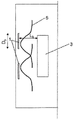
본 발명의 맥락에서 효율 증가와 관련하여 위에서 설명한 태양들 중의 일부를 더 잘 설명하기 위하여, 도 1 및 도 2는 구성 형태가 서로 상이한 2개의 코팅 챔버를 도시한다. 도 1에서, 각각의 직경(Db)을 갖는 2개의 원형 타겟(1)들이 코팅될 기판(3)으로부터 거리(Lb) 만큼 떨어져 코팅 챔버에 배치된다. 도 2에서, 각각의 직경(Ds)을 갖는 3개의 원형 타겟(1)들이 코팅될 기판(3)으로부터 거리(Ls) 만큼 이격되게 챔버에 배치된다. 도 2는 아크 소스들이 보다 조밀하게 패킹된 코팅 구형 형태를 도시하는데, 이는 캐소드에서 캐소드까지의 거리가 더 짧기 때문이고 심지어는, 더 작은 타겟 직경들이 사용될 때(Db > Ds) 특히 가능한 것처럼, 캐소드에서 기판까지의 거리가 더 짧을 수 있기(Lb > Ls) 때문이다. 이는 예를 들어 도 1 및 도 2에 도시된 구성 형태들의 개략적인 도면들을 보고 비교하는 것에 의해 알 수 있다.To better illustrate some of the aspects described above in relation to increasing efficiency in the context of the present invention, FIGS. 1 and 2 show two coating chambers with different configurations. In Fig. 1, two
본 발명에 따른 아크 소스의 위에서 설명한 실시예들을 사용하는 것에 의해, 종래 기술의 단점을 극복하는 것이 그리고 아래의 장점을 얻는 것이 가능하다.By using the above-described embodiments of the arc source according to the invention, it is possible to overcome the disadvantages of the prior art and to obtain the following advantages.
- 소스들 간의 "크로스 토크(cross talk)" 관리("크로스 토크"라는 용어는 자기장 크로스 토크, 즉 2개 이상의 아크 소스의 2개 이상의 자기장 간의 자기 간섭을 의미함).-Management of "cross talk" between sources (the term "cross talk" means magnetic field cross talk, ie magnetic interference between two or more magnetic fields of two or more arc sources).
- 이용 가능한 자기 시스템들 및 이용 가능한 아크 기화 기술들과 호환될 수 있는 새로운 특성을 갖는 새로운 아크 소스 개발.-Development of a new arc source with new characteristics compatible with available magnetic systems and available arc vaporization technologies.
- 직경이 보다 작은 타겟들의 사용(이는 특히 적절한 애노드 또는 애노드들을 설계하는 것에 의한 그리고 자기장을 생성하기 위한 적절한 자기 시스템을 설계하는 것에 의한 어려움 때문임).-Use of smaller diameter targets (this is particularly due to the difficulty by designing a suitable anode or anodes and by designing a suitable magnetic system to generate a magnetic field).
주변 쉴드(본 발명의 맥락에서 고 투자율 회로에 통합된 자기 쉴드라고도 함) 사용에 대한 추가 설명Additional explanation for the use of peripheral shields (also called magnetic shields integrated into high permeability circuits in the context of the present invention)
본 발명에 따른 새로운 아크 소스는 도 3b에 도시된 바와 같이 차단된 자기장을 사용하는 것에 의해 좁은 소스 대 소스 거리를 나타내는 아크 소스 장치(캐소드 장치라고도 함)를 구현할 수 있게 한다.The new arc source according to the present invention makes it possible to implement an arc source device (also called a cathode device) exhibiting a narrow source to source distance by using a blocked magnetic field as shown in FIG. 3B.
위에서 이미 설명한 바와 같이, 아크 소스에 연질 자성 재료 쉴딩(강자성 재료로 만들어진 주변 쉴드라고도 함), 예를 들어 연철 쉴딩 또는 저탄소강 쉴딩을 제공하는 것에 의해 차단된 자기장(이하 분로 자기 루프라고도 함)이 본 발명에 따라 달성될 수 있다. 이러한 방식으로, 자기장 발생 수단의 연질 자성 재료 분로(예를 들어, 연철 분로)가 자기 간섭을 10배 이상 감소시킬 수 있다. 이러한 조합은 축대칭 애노드 획정에 또한 중요한데, 특히 이는 이러한 방식으로 원형 타겟을 둘러싸며 모든 방향들에서 동일한 효과를 나타내는(달리 말하면, 애노드를 형성하는 모든 지점들에서 대칭으로) 하나 이상의 환형 애노드를 사용하는 것이 가능하기 때문이다.As already described above, the magnetic field blocked by providing a soft magnetic material shielding (also called a peripheral shield made of ferromagnetic material) to the arc source, e.g., soft iron shielding or low carbon steel shielding (hereinafter also referred to as shunt magnetic loop) It can be achieved according to the invention. In this way, a soft magnetic material shunt (eg, soft iron shunt) of the magnetic field generating means can reduce magnetic interference by more than 10 times. This combination is also important for defining axisymmetric anodes, in particular it uses one or more annular anodes which in this way surround the circular target and exhibit the same effect in all directions (in other words, symmetrically at all points forming the anode). Because it is possible.
도 3은 종래 기술에 따른 개방된 자기 루프를 이용하는 것(도 3a 참조)과 본 발명에 따른 차단된 자기장(도 3b 참조)을 이용하는 것 간의 비교를 도시한다.Fig. 3 shows a comparison between using an open magnetic loop according to the prior art (see Fig. 3a) and using a blocked magnetic field (see Fig. 3b) according to the invention.
이러한 예시적인 예로부터, 도 3a에 도시된 바와 같은 개방된 자기 루프를 사용하면, 이웃한 소스들이 서로 가깝게 배치되면 인접 소스들과의 간섭을 초래할 것이 분명하다.From this illustrative example, it is clear that using an open magnetic loop as shown in FIG. 3A will cause interference with adjacent sources if adjacent sources are placed close to each other.
달리 말하면, 제1 아크 소스가 개방된 자기 루프를 이용하여 작동되면, 일부 자기 라인들이 아크 소스(10)의 타겟(10) 옆에 있는 반경 방향 거리를 따라 연장할 것이다. 이러한 자기 라인들을 본 발명의 맥락에서 외부 자기 라인들(MLE)이라 하며, 이들은 도 3a에 예시적으로 도시되어 있다. 이 예로부터, 이웃한 소스가 다른 소스의 외부 자기 라인(MLE)들이 차지하는 영역 내에 포함된 반경 방향 거리에 배치되는 경우, 이웃한 소스와의 간섭을 초래할 것은 분명하다.In other words, if the first arc source is operated using an open magnetic loop, some magnetic lines will extend along the radial distance next to the
본 발명을 더 잘 설명하기 위하여, 외부 자기 라인(MLE)이 따라서 연장하는 아크 소스(10) 옆의 반경 방향 거리는 외부 자기 라인을 포함하는 반경 거리라 할 것이고, 도 3에 지시된 바와 같이 LRDMLE로 표시될 것이다.To better illustrate the present invention, the radial distance next to the
본 발명에 따르면, 도 3b에 예시적으로 도시된 바와 같이 차단된 자기장이 사용된다. 이 경우, 아크 소스(10) 옆의 반경 방향으로 긴 거리를 따라 연장될 수 있는 외부 자기 라인(MLE)은 없으며, 결과적으로 외부 자기 라인을 포함하는 반경 거리는 실질적으로 0, 즉 LRDMLE = 0이다. 이러한 방식으로, 이웃하는 소스와의 간섭을 초래하지 않으면서 2개 이상의 소스를 서로 간에 보다 가까운 반경 방향 거리에 배치할 수 있다.According to the present invention, a blocked magnetic field is used as exemplarily shown in FIG. 3B. In this case, there is no external magnetic line M LE that can extend along a long distance in the radial direction next to the
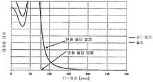
도 4는 2개의 원형 타겟을 사용하여 생성된 조건을 고려하여 계산된 자기장 라인들을 나타내는 그래프인데, 각각의 타겟은 직경이 100mm이고 타겟들은 대략 150mm의 타겟 대 타겟 거리로 배치된다(이하 타겟 대 타겟 거리를 또한 TT 거리라고도 함 - 이 거리는 반경 방향으로 나란히 배열된 2개의 이웃 간의 거리로 이해해야 하고, 이 거리는 2개의 이웃 타겟 중 하나의 타겟의 중심점으로부터 다른 이웃 타겟의 중심점까지 반경 방향으로 측정됨).FIG. 4 is a graph showing magnetic field lines calculated in consideration of a condition generated using two circular targets, each target having a diameter of 100 mm and targets arranged at a target to target distance of approximately 150 mm (hereinafter target to target) Distance is also known as TT distance-this distance should be understood as the distance between two neighbors arranged in a radial direction, which is measured radially from the center point of one of the two neighbor targets to the center point of the other neighbor target) .
도 4에서, 개방된 자기 루프를 구비하는(연철 쉴딩이 없는) 아크 소스들 및 분로된 자기 루프를 구비하는(연철 쉴딩이 있는) 본 발명의 아크 소스들이 사용될 때 반경 방향을 따라 자기장의 크기 분포에 있어서 차이를 관찰할 수 있다. 분로된 자기 루프를 구비하는 본 발명의 아크 소스들이 사용될 때, 150mm 미만의 TT 거리에서 자기장의 크기는 무시할 수 있거나 혹은 연철 쉴딩의 효과에 의해 완전히 상쇄된다. 반대로, 개방된 자기 루프를 구비하는 아크 소스들이 사용될 때, 적어도 250mm의 TT 거리에서만 자기장의 크기를 무시할 수 있다.In FIG. 4, the size distribution of the magnetic field along the radial direction when arc sources with an open magnetic loop (without soft iron shielding) and arc sources of the invention with a shunted magnetic loop (with soft iron shielding) are used In the difference can be observed. When the arc sources of the present invention with a shunted magnetic loop are used, the magnitude of the magnetic field at a TT distance of less than 150 mm is negligible or completely canceled out by the effect of soft iron shielding. Conversely, when arc sources with an open magnetic loop are used, the magnitude of the magnetic field can be neglected only at a TT distance of at least 250 mm.
본 발명에 따른 새로운 아크 소스는 또한 자기장 구성 형태에 관해 높은 유연성을 허용하도록 설계될 수 있다. 특히 본 발명의 맥락에서 공간 분포 및 자기장 세기가 독립적으로 조정될 수 있도록 설계된다는 것을 의미한다. 이러한 방식으로, 축대칭 구성 형태로 된 자기장에 대한 넓은 범위의 자석 조정성에 관하여 고도의 유연성을 달성할 수 있다. The new arc source according to the present invention can also be designed to allow high flexibility with respect to the magnetic field configuration. In particular, it means that in the context of the present invention, the spatial distribution and magnetic field strength are designed to be independently adjustable. In this way, it is possible to achieve a high degree of flexibility with respect to a wide range of magnet adjustability for a magnetic field in the form of an axisymmetric configuration.
도 5는 자석 구성 형태들을 이용하여 조정할 수 있는 축대칭 구성 형태로 된 자기장의 다양한 범위를 나타낸다.5 shows various ranges of magnetic fields in an axisymmetric configuration that can be adjusted using magnetic configuration types.
자기장 생성, 특히 3개의 전자기 코일을 구비한 자기 시스템(자기 유도 시스템이라고도 함)을 사용한 자기장 생성에 대한 추가 설명Additional description of magnetic field generation, especially magnetic field generation using a magnetic system with three electromagnetic coils (also called a magnetic induction system)
바람직하게는 본 발명의 아크 소스는 전자기 코일 및 연질 자성 재료(강자성 재료라고도 함)를 포함하는 자기 시스템을 포함한다. 이러한 바람직한 실시예의 경우, 순철이 매우 적합한 연질 자성 재료이다. 또한, 저탄소강이 연질 자성 재료로 적합하고, 위에서 언급한 강자성 재료조차 이러한 바람직한 실시예를 위한 연질 자성 재료로 적합하다.Preferably, the arc source of the present invention comprises a magnetic system comprising an electromagnetic coil and a soft magnetic material (also called a ferromagnetic material). For this preferred embodiment, pure iron is a very suitable soft magnetic material. In addition, low-carbon steel is suitable as a soft magnetic material, and even the above-mentioned ferromagnetic material is suitable as a soft magnetic material for this preferred embodiment.
바로 위에서 언급한 바람직한 실시예의 바람직한 변형예에 따르면, 자기 시스템은 전자기 코일로만 만들어진다(이후 이러한 자기 시스템을 코일 시스템이라고도 함).According to a preferred variant of the preferred embodiment just mentioned above, the magnetic system is made only of an electromagnetic coil (hereinafter this magnetic system is also referred to as a coil system).
도 6은 바로 위에서 언급한 변형예에 따른 본 발명의 아크 소스(2)를 개략적으로 도시한다. 이 변형예에서, 2개의 전자기 코일(C1, C2)이 외부(주변) 자석 링으로 작용하기 위해 사용된다. 이러한 2개의 코일(C1, C2)은 서로를 상쇄할 수 있는 방식으로 배열되어야 한다. 이러한 2개의 코일(C1, C2)은 예를 들어 역평행하게 분극화될 수 있다. C1과 C2의 관계(C1/C2)는 자기 초점을 결정한다. 본 발명의 아크 소스의 이러한 변형예의 코일 시스템은 바람직하게는 중심 영역(중심 구역)에 배치되는 제3 코일을 또한 포함하고, 이러한 제3 코일은 타겟의 중심 및 자기장 세기의 크기에 영향을 미친다. 이러한 코일 시스템은 동등한 영구 자석으로 된 장치와 동일한 자기장을 생성할 수 있으며, 자석을 움직이지 않고도 자기장 세기를 수정할 수 있는 커다란 장점을 갖는다. 전자기 코일(C1, C2, C3)은 연질 자성 재료(20), 바람직하게는 순철 또는 저탄소강으로 둘러싸여 있다.Figure 6 schematically shows the arc source 2 of the present invention according to the variant mentioned immediately above. In this variant, two electromagnetic coils C1 and C2 are used to act as external (peripheral) magnetic rings. These two coils (C1, C2) should be arranged in a way that can cancel each other. These two coils C1, C2 can be polarized, for example, antiparallel. The relationship between C1 and C2 (C1/C2) determines self-focus. The coil system of this variant of the arc source of the present invention preferably also includes a third coil disposed in the central region (central region), which influences the magnitude of the center and magnetic field strength of the target. Such a coil system can generate the same magnetic field as a device made of equivalent permanent magnets, and has a great advantage of being able to correct the magnetic field strength without moving the magnet. The electromagnetic coils C1, C2, C3 are surrounded by a soft
연질 자성 물질 쉴딩(15)(바람직하게는 순철로 제조됨)이 도 6에 또한 도시되어있다.A soft magnetic material shield 15 (preferably made of pure iron) is also shown in FIG. 6.
위에서 언급한 바람직한 실시예의 다른 바람직한 변형예에 따르면, 언급한 자기 시스템은 영구 자석 및 제어 코일로 사용되는 하나의 전자기 코일로 만들어진다.According to another preferred variant of the preferred embodiment mentioned above, the magnetic system mentioned is made of a permanent magnet and one electromagnetic coil used as a control coil.
본 발명의 위에서 설명한 실시예들과 관련하여, 다음을 고려하는 것이 중요하다.With regard to the above-described embodiments of the present invention, it is important to consider the following.
- 코일 기구의 냉각이 필요함-Cooling of coil mechanism is required
- 연질 자성 재료가 높은 포화 자속 밀도와 낮은 잔류성을 가져야 함.-The soft magnetic material should have a high saturation magnetic flux density and low persistence.
도 7은 코팅 챔버의 벽 높이를 따라 보다 조밀하게 패킹된 분포 방식으로 분포된 5개의 본 발명 아크 소스를 이용하는 것에 의해, 동일한 코팅 챔버의 동일한 벽 높이를 따라 분포된 3개의 본 발명 아크 소스들을 이용한 것과 비교하여, 증착된 AlTiN 코팅의 증착 속도(임의의 단위)에 대한 고도의 균일성을 나타낸다. 비교를 가능하게 하기 위하여, 두 경우 모두에서 동일한 코팅 파라미터들이 사용되었다. 두 경우 모두에서 고도의 균일성이 얻어질 수 있지만 더 많은 양의 아크 소스를 사용하는 것에 의해, 이 경우에는 5개의 아크 소스를 사용하는 것에 의해 특별히 더 고도한 균일성(즉, ±10% 미만의 저도의 비균일성)이 달성될 수 있음을 관찰할 수 있다.FIG. 7 uses three inventive arc sources distributed in a more densely packed distribution manner along the wall height of the coating chamber, using three inventive arc sources distributed along the same wall height of the same coating chamber. Compared to that, it exhibits a high degree of uniformity over the deposition rate (arbitrary units) of the deposited AlTiN coating. To facilitate comparison, the same coating parameters were used in both cases. A high degree of uniformity can be obtained in both cases, but a higher degree of uniformity (i.e. less than ±10%) is achieved by using a larger amount of arc sources, in this
도 8은 본 발명이 아닌 아크 소스들을 포함하는 코팅 장치를 사용하는 것에 의한 증착 속도(임의 단위)와 본 발명의 아크 소스들을 포함하는 코팅 장치를 사용하는 것에 의한 증착 속도(임의 단위) 간의 비교를 도시한다. 코팅 라인 당 속도를 고려했다. 본 발명의 아크 소스들을 구비하는 장치를 사용하는 것에 의해 증착 속도가 대략 2배 증가되었다.Figure 8 compares the deposition rate (arbitrary units) by using a coating device comprising arc sources of the present invention and the deposition rate (arbitrary units) by using a coating device comprising arc sources of the present invention. City. The speed per coating line was considered. The deposition rate was approximately doubled by using an apparatus with arc sources of the present invention.
도 9는 본 발명이 아닌 아크 소스들을 포함하는 코팅 장치를 사용하는 것에 의한 그리고 본 발명의 아크 소스들을 포함하는 코팅 장치를 사용하는 것에 의한 코팅 부피/증발된 재료에 대해 계산된 코팅 효율 비교를 도시한다. 본 발명의 아크 소스들을 구비하는 장치를 이용하는 것에 의해 타겟으로부터 증발되는 재료의 이용에 있어 대략 50%가 증가되었다. 이는 타겟으로부터 증발된 재료로부터, 본 발명의 아크 소스들을 이용하는 것에 의해 코팅될 기판 표면에 대략 50% 더 증착되었다는 것을 의미한다.FIG. 9 shows the calculated coating efficiency comparison for coating volume/evaporated material by using a coating device comprising arc sources other than the present invention and by using a coating device comprising arc sources of the present invention. do. By using an apparatus with arc sources of the present invention an increase of approximately 50% in the use of material evaporated from the target. This means that from the material evaporated from the target, approximately 50% more was deposited on the substrate surface to be coated by using the arc sources of the present invention.
결과들은 도 8에 나타나 있다.Results are shown in FIG. 8.
- 본 발명이 아닌 예: 2개의 본 발명이 아닌 아크 소스로, 각각의 아크 소스는 직경이 150mm인 타겟을 포함하고 150A의 아크 전류를 사용하여 작동되며, 본 발명이 아닌 아크 소스들은 400mm의 코팅 챔버 벽 높이를 따라 배열됨.-Non-invention example: Two non-invention arc sources, each arc source comprising a target having a diameter of 150 mm and operated using an arc current of 150 A, arc sources other than the invention being coated with 400 mm. Arranged along chamber wall height.
- 본 발명의 예: 3개의 본 발명 아크 소스로, 각각의 아크 소스는 직경이 150mm인 타겟을 포함하고 150A의 아크 전류를 사용하여 작동되며, 3개의 본 발명 아크 소스는 500mm의 코팅 챔버 벽 높이를 따라 배열됨.Examples of the present invention: three inventive arc sources, each arc source comprising a target having a diameter of 150 mm and operated using an arc current of 150 A, three inventive arc sources having a coating chamber wall height of 500 mm Arranged along.
2개의 본 발명이 아닌 아크 소스 대신 3개의 본 발명 아크 소스가 사용되었기 때문에, 증착 속도가 1.5배 증가할 것으로 예상되었지만 약 2배로 증가했기 때문에 상당히 더 높게 증가했다. 이러한 결과들은 본 발명에 따른 아크 소스들을 사용함으로써 얻을 수 있는 효율 측면에서 상당한 장점이 있음을 입증한다.Since three inventive arc sources were used instead of the two non-invention arc sources, the deposition rate was expected to increase by a factor of 1.5, but increased significantly by about a factor of two. These results demonstrate that there are significant advantages in terms of the efficiency obtainable by using the arc sources according to the invention.
결과들은 도 9에 나타나 있다.Results are shown in FIG. 9.
- 본 발명이 아닌 예: 2개의 본 발명이 아닌 아크 소스로, 각각의 아크 소스는 직경이 150mm인 타겟을 포함하고 200A의 아크 전류를 사용하여 작동되며, 본 발명이 아닌 아크 소스들은 400mm의 코팅 챔버 벽 높이를 따라 배열됨.-Non-invention example: Two non-invention arc sources, each arc source comprising a target with a diameter of 150 mm and operated using an arc current of 200 A, arc sources other than the invention being coated with 400 mm. Arranged along chamber wall height.
- 본 발명의 예: 3개의 본 발명 아크 소스로, 각각의 아크 소스는 직경이 150mm인 타겟을 포함하고 200A의 아크 전류를 사용하여 작동되며, 3개의 본 발명 아크 소스는 500mm의 코팅 챔버 벽 높이를 따라 배열됨.Examples of the invention: three inventive arc sources, each arc source comprising a target having a diameter of 150 mm and operated using an arc current of 200 A, the three inventive arc sources are 500 mm coated chamber wall height Arranged along.
각각의 경우(즉, 본 발명이 아닌 아크 소스들을 이용하는 경우와 본 발명의 아크 소스들을 이용하는 경우), 코팅 부피를 전체 증발된 재료로 나눈 관계를 계산하여 효율을 결정했다. 계산을 위해, 코팅된 기판 위에 증착된 코팅의 전체 부피 및 타겟으로부터 증발된 전체 재료가 결정되었다. 증발된 전체 재료는 코팅 후 각각의 타겟에서의 부식을 측정하고 각각의 타겟에 대해 증발된 물질에 상응하는 부식 부피를 더하는 것에 의해 결정되었다. 본 발명의 아크 소스들을 사용하는 것에 의해 약 1.5배 증가했다. 이러한 결과는 본 발명에 따른 아크 소스를 사용함으로써 달성될 수 있는 효율 측면에서 상당한 장점이 있음을 입증한다.In each case (ie, using arc sources other than the present invention and using arc sources of the present invention), the efficiency was determined by calculating the relationship of dividing the coating volume by the total evaporated material. For calculation, the total volume of coating deposited on the coated substrate and the total material evaporated from the target were determined. The total evaporated material was determined by measuring the corrosion at each target after coating and adding the corresponding corrosion volume to the evaporated material for each target. It was increased by about 1.5 times by using the arc sources of the present invention. These results demonstrate that there are significant advantages in terms of the efficiency that can be achieved by using the arc source according to the invention.
본 발명에 따른 아크 소스들을 사용함으로써 제공되는 가장 중요한 장점들의 요약Summary of the most important advantages provided by using arc sources according to the invention
위에서 설명한 바와 같이 신규하고 혁신적인 아크 소스들을 구성하기 위한 하나 이상의 속성을 선택하는 것에 의해, 다음의 목적들 중 하나 이상을 달성하는 것이 가능하다.By selecting one or more attributes to construct new and innovative arc sources as described above, it is possible to achieve one or more of the following objectives.
- 높은 효율과 생산성.-High efficiency and productivity.
- 자기장 변화에 있어서의 높은 유연성.-High flexibility in changing magnetic fields.
- 반응 가스와 무관한 반응 대기 내에서의 효율적인 작업은, 예컨대 고도로 이온화된 질소 가스 또는 저도로 이온화된 질소 가스가 필요하다면, 가스 이온화 또는 저도의 이온화임.Efficient work in a reaction atmosphere independent of the reaction gas is gas ionization or low ionization, for example if highly ionized nitrogen gas or low ionized nitrogen gas is required.
- 임의의 종류의 코팅, 예컨대 질화물, 산화물, 탄화물 또는 이들의 조합의 증착의 유연성.-Flexibility of deposition of any kind of coating, such as nitride, oxide, carbide or combinations thereof.
- 아크 소스 작동 중의 전체 효율을 증가시키는 것, 특히-To increase the overall efficiency during arc source operation, in particular
o 에너지 효율 향상o Improve energy efficiency
o 캐소드 재료로부터 증발되는 코팅 재료의 최대 활용과 관련된 효율 증가o Increased efficiency associated with maximum utilization of the coating material evaporated from the cathode material
o 코팅 필름 증착 속도 증가에 의한o Coating film deposition rate increases
작업 비용의 절감.Reduced operating costs.
Claims (11)
- 냉각 판(11), 캐소드 요소로서의 타겟(1)을 포함하는 캐소드 어셈블리,
- 전극, 및
- 타겟(1)의 배면(1B) 전방에 배치되는 자기 유도 시스템을 포함하고,
타겟은 바람직하게는 디스크형 타겟이지만 예를 들어 직사각형 타겟일 수 있고, 타겟(10)은 횡방향 두께, 증발되도록 배치되는 전면(1A) 및 배면(1B)을 구비하며, 전면(1A)은 배면(1B)과 평행하고, 이들 양면은 타겟(1)의 두께만큼 서로 이격되어 있고, 캐소드 어셈블리는 가로 방향의 전체 높이를 가지며 그리고 임의의 길이 방향으로 전체 폭을 획정하는 경계들을 구비하고,
전극은 전극과 타겟(1)의 전면(1A) 사이에 타겟(1)의 전면(1A)의 적어도 일부를 증발시키기 위한 아크가 형성될 수 있도록 배열되고, 그리고
자기 유도 시스템은, 전극과 타겟(1)의 전면(1A) 사이에 아크가 형성될 때, 아크가 타겟(1)에 접촉함으로써 발생되는 캐소드 스팟을 유도하기 위해 타겟의 횡단면을 통과하여 그리고 타겟(1)의 전면(1A) 전방에 있는 공간을 따라 연장하는 자기장 라인들을 포함하는 전체 자기장을 발생시키는 하나 이상의 자기장을 생성하는 수단을 포함하는, 아크 증발기에 있어서,
- 캐소드 어셈블리의 경계들이 강자성 재료로 만들어지는 주변 쉴드(15)를 포함하고, 주변 쉴드(15)는 가로 방향으로 전체 높이(H)를 가지며, 상기 전체 높이(H)는 임의의 길이 방향으로 연장하는 자기장 라인들의 차폐 효과를 발생시키고 이러한 방식으로 캐소드 어셈블리의 경계들을 임의의 길이 방향으로 자기장 라인들이 연장하는 한계로서 확립시키는 성분(C)을 포함하는 것을 특징으로 하는 아크 증발기.With arc evaporator,
-A cathode assembly comprising a cooling plate 11, a target 1 as a cathode element,
-Electrodes, and
-A magnetic induction system disposed in front of the back surface 1B of the target 1,
The target is preferably a disc-shaped target, but may be, for example, a rectangular target, and the target 10 has a lateral thickness, front 1A and rear 1B arranged to be evaporated, and front 1A is rear Parallel to (1B), these two sides are spaced from each other by the thickness of the target 1, the cathode assembly has a total height in the transverse direction and has boundaries defining an overall width in an arbitrary longitudinal direction,
The electrodes are arranged such that an arc for evaporating at least a portion of the front surface 1A of the target 1 can be formed between the electrode and the front surface 1A of the target 1, and
The magnetic induction system, when an arc is formed between the electrode and the front surface 1A of the target 1, passes through the cross section of the target and induces the target ( 1. An arc evaporator comprising means for generating one or more magnetic fields that generate a total magnetic field comprising magnetic field lines extending along a space in front of the front 1A of 1),
-The borders of the cathode assembly include a peripheral shield 15 made of ferromagnetic material, the peripheral shield 15 has a total height H in the transverse direction, and the total height H extends in any length direction Characterized in that it comprises the component (C), which creates a shielding effect of the magnetic field lines and in this way establishes the boundaries of the cathode assembly as a limit by which the magnetic field lines extend in any longitudinal direction.
캐소드 어셈블리가 타겟 직경(D1)을 갖는 디스크형 타겟을 포함하는 대칭적인 구성 형태 및 전체 직경(D)을 가지며, 성분(C)은 D/20 ≤ C ≤ D/5의 범위인 값을 갖는 것을 특징으로 하는 아크 증발기.The method according to claim 1,
The cathode assembly has a symmetrical configuration and a total diameter (D) comprising a disc-shaped target having a target diameter (D1), and the component (C) has a value in the range of D/20 ≤ C ≤ D/5 Arc evaporator characterized by.
타겟 직경이 100mm ≤ D1 ≤ 150mm 범위이고, 캐소드 어셈블리의 전체 직경은 150mm ≤ D ≤ 200mm 범위인 것을 특징으로 하는 아크 증발기.The method according to claim 1 or claim 2,
Arc evaporator characterized in that the target diameter is in the range of 100 mm ≤ D1 ≤ 150 mm, and the overall diameter of the cathode assembly is in the range of 150 mm ≤ D ≤ 200 mm.
강자성 재료가 순철 또는 ARMCO 순철 또는 구조용 강 또는 마르텐사이트 크롬강인 것을 특징으로 하는 아크 증발기.The method according to any one of claims 1 to 3,
Arc evaporator characterized in that the ferromagnetic material is pure iron or ARMCO pure iron or structural steel or martensite chromium steel.
강자성 재료가 구조용 강 S355J2인 것을 특징으로 하는 아크 증발기.The method according to claim 4,
Arc evaporator, characterized in that the ferromagnetic material is structural steel S355J2.
아크 소스의 자기 유도 시스템이 중양 영역에 배치된 적어도 하나의 자기장을 생성하기 위한 수단 및 주변 영역에 있는 적어도 하나의 추가 자기장을 생성하기 위한 수단을 포함하며, 이러한 방식으로 생성된 자기장들은 아크를 유도하고 타겟(1A)의 전면에서 캐소드 스팟 경로를 제어하기 위한 전체 자기장을 발생시키는 것을 특징으로 하는 아크 증발기.The method according to any one of claims 1 to 6,
The magnetic induction system of the arc source comprises means for generating at least one magnetic field disposed in the heavy region and means for generating at least one additional magnetic field in the peripheral region, the magnetic fields generated in this way induce the arc And generating an entire magnetic field for controlling the cathode spot path in front of the target 1A.
중앙 영역에 배치된 수단은 자기장을 생성하기 위한 하나의 전자기 코일(C3)을 포함하고, 주변 영역에 배치된 수단은 2개의 추가 자기장을 생성하기 위한 2개의 전자기 코일(C1, C2)을 포함하는 것을 특징으로 하는 아크 증발기.The method according to claim 6,
Means disposed in the central region include one electromagnetic coil (C3) for generating a magnetic field, and means disposed in the peripheral region comprise two electromagnetic coils (C1, C2) for generating two additional magnetic fields. Arc evaporator, characterized in that.
자기장을 생성하기 위한 수단은 영구 자석들 및 자기장 특성의 변화를 발생시키기 위한 제어 코일로 사용될 단 하나의 전자기 코일을 포함하는 것을 특징으로 하는 아크 증발기.The method according to claim 6,
The means for generating a magnetic field comprises permanent magnets and only one electromagnetic coil to be used as a control coil for generating a change in magnetic field properties.
자기 유도 시스템이 자기장 생성 수단을 둘러싸도록 배치되는 강자성 재료(20)를 포함하고, 강자성 재료(20)는 자기장 생성 수단을 에워싸도록 분포되지만 자기 유도 시스템과 캐소드 어셈블리 사이에는 강자성 재료(20)가 배치되지 않는 것을 특징으로 하는 아크 증발기.The method according to any one of the preceding claims,
The magnetic induction system includes a ferromagnetic material 20 disposed to surround the magnetic field generating means, and the ferromagnetic material 20 is distributed so as to surround the magnetic field generating means, but the ferromagnetic material 20 is between the magnetic induction system and the cathode assembly. Arc evaporator, characterized in that it is not disposed.
자기 유도 시스템이 자기장 생성 수단을 둘러싸도록 배치되는 강자성 재료(20)를 포함하고, 강자성 재료(20)는 자기장 생성 수단을 부분적으로 에워싸도록 배치되지만 자기 유도 시스템과 캐소드 어셈블리 사이에는 강자성 재료(20)가 배치되지 않으며, 중앙 영역에 배치된 전자기 코일(C3)의 길이(S)를 갖는 상부 부분 및 주변 영역에 배치되면서 중앙 영역에 배치된 전자기 코일에 가장 가까운 전자기 코일(C2)의 길이(S')를 갖는 상부 부분은 강자성 재료(20)에 의해 둘러싸이지 않고, 그 결과 공기를 포함하는 공간(Spc)이 형성되며, 이러한 방식으로, 생성된 자기장의 합으로부터 발생되는 전체 자기장이 공기를 포함하는 상기 공간(Spc)을 구비하지 않는 유사한 아크 증발기와 비교하여 타겟(1)의 전면(1A)과 평행한 자기장 라인들을 더 많이 나타내는 것을 특징으로 하는 아크 증발기.The method according to claim 7,
The magnetic induction system includes a ferromagnetic material 20 disposed to surround the magnetic field generating means, and the ferromagnetic material 20 is arranged to partially enclose the magnetic field generating means, but between the magnetic induction system and the cathode assembly, a ferromagnetic material 20 ) Is not disposed, and the length of the electromagnetic coil C2 closest to the electromagnetic coil disposed in the central region while being disposed in the upper portion and the peripheral region having the length S of the electromagnetic coil C3 disposed in the central region (S) The upper portion with') is not surrounded by the ferromagnetic material 20, and as a result, a space Spc containing air is formed, and in this way, the entire magnetic field generated from the sum of the generated magnetic fields contains air. The arc evaporator, characterized in that it shows more magnetic field lines parallel to the front surface (1A) of the target (1) compared to a similar arc evaporator without the space (Spc).
상부 길이(S)는 3mm ≤ S ≤ 15mm 범위이고, 타겟 직경(D1)은 100mm ≤ D1 ≤ 150mm 범위이고 캐소드 어셈블리의 전체 직경이 150mm ≤ D ≤ 200mm 범위인 것을 특징으로 하는 아크 증발기.The method according to claim 10,
The arc evaporator, characterized in that the upper length (S) is in the range of 3 mm ≤ S ≤ 15 mm, the target diameter (D1) is in the range of 100 mm ≤ D1 ≤ 150 mm and the overall diameter of the cathode assembly is in the range of 150 mm ≤ D ≤ 200 mm.
Applications Claiming Priority (3)
| Application Number | Priority Date | Filing Date | Title |
|---|---|---|---|
| US201762567423P | 2017-10-03 | 2017-10-03 | |
| US62/567,423 | 2017-10-03 | ||
| PCT/EP2018/000459 WO2019081052A1 (en) | 2017-10-03 | 2018-10-04 | Arc source with confined magnetic field |
Publications (1)
| Publication Number | Publication Date |
|---|---|
| KR20200063203A true KR20200063203A (en) | 2020-06-04 |
Family
ID=64572281
Family Applications (2)
| Application Number | Title | Priority Date | Filing Date |
|---|---|---|---|
| KR1020207012635A KR20200063204A (en) | 2017-10-03 | 2018-10-04 | Arc source |
| KR1020207012634A KR20200063203A (en) | 2017-10-03 | 2018-10-04 | Arc source with limited magnetic field |
Family Applications Before (1)
| Application Number | Title | Priority Date | Filing Date |
|---|---|---|---|
| KR1020207012635A KR20200063204A (en) | 2017-10-03 | 2018-10-04 | Arc source |
Country Status (11)
| Country | Link |
|---|---|
| US (2) | US11306390B2 (en) |
| EP (2) | EP3692184B1 (en) |
| JP (2) | JP7344483B2 (en) |
| KR (2) | KR20200063204A (en) |
| CN (2) | CN111315915A (en) |
| BR (2) | BR112020006715A2 (en) |
| CA (2) | CA3077570A1 (en) |
| MX (2) | MX2020003372A (en) |
| RU (2) | RU2020113430A (en) |
| SG (2) | SG11202002991YA (en) |
| WO (2) | WO2019081053A1 (en) |
Families Citing this family (1)
| Publication number | Priority date | Publication date | Assignee | Title |
|---|---|---|---|---|
| US20220307125A1 (en) * | 2019-07-03 | 2022-09-29 | Oerlikon Surface Solutions Ag, Pfäffikon | Cathodic arc source |
Family Cites Families (22)
| Publication number | Priority date | Publication date | Assignee | Title |
|---|---|---|---|---|
| US4448659A (en) * | 1983-09-12 | 1984-05-15 | Vac-Tec Systems, Inc. | Method and apparatus for evaporation arc stabilization including initial target cleaning |
| US4724058A (en) * | 1984-08-13 | 1988-02-09 | Vac-Tec Systems, Inc. | Method and apparatus for arc evaporating large area targets |
| US5298136A (en) * | 1987-08-18 | 1994-03-29 | Regents Of The University Of Minnesota | Steered arc coating with thick targets |
| RU2074904C1 (en) | 1992-11-23 | 1997-03-10 | Евгений Николаевич Ивашов | Cathode joint for ionic-plasma application of thin films in vacuum |
| RU2135634C1 (en) | 1998-06-15 | 1999-08-27 | Санкт-Петербургский государственный технический университет | Method and device for magnetron sputtering |
| US6929727B2 (en) * | 1999-04-12 | 2005-08-16 | G & H Technologies, Llc | Rectangular cathodic arc source and method of steering an arc spot |
| US6645354B1 (en) * | 2000-04-07 | 2003-11-11 | Vladimir I. Gorokhovsky | Rectangular cathodic arc source and method of steering an arc spot |
| US20040112736A1 (en) * | 2001-03-27 | 2004-06-17 | Larrinaga Josu Goikoetxea | Arc evaporator with a poweful magnetic guide for targets having a large surface area |
| DE10127013A1 (en) * | 2001-06-05 | 2002-12-12 | Gabriel Herbert M | Electric arc vaporizing device used for coating substrates with hard material has element of high relative magnetic permeability assigned to at least one annular coil of magnetic arrangement |
| EP1970464B1 (en) | 2005-12-16 | 2010-03-03 | Fundacion Tekniker | Cathode evaporation machine |
| EP2018653B1 (en) * | 2006-05-16 | 2014-08-06 | Oerlikon Trading AG, Trübbach | Arc source and magnet arrangement |
| CN101358328A (en) | 2007-12-28 | 2009-02-04 | 中国科学院金属研究所 | Arc source of dynamic controlled arc ion plating |
| US20110315544A1 (en) * | 2008-12-26 | 2011-12-29 | Fundacion Tekniker | Arc evaporator and method for operating the evaporator |
| WO2011021281A1 (en) * | 2009-08-19 | 2011-02-24 | 日新電機株式会社 | Arc evaporation source, and vacuum evaporation apparatus |
| US20130220800A1 (en) | 2010-05-04 | 2013-08-29 | Oerlikon Trading Ag, Trubbach | Method for spark deposition using ceramic targets |
| UA101678C2 (en) * | 2011-04-08 | 2013-04-25 | Национальный Научный Центр "Харьковский Физико-Технический Институт" | Vacuum arc evaporator FOR GENERATING cathode plasma |
| US9153422B2 (en) | 2011-08-02 | 2015-10-06 | Envaerospace, Inc. | Arc PVD plasma source and method of deposition of nanoimplanted coatings |
| CN102534513B (en) * | 2011-12-19 | 2014-04-16 | 东莞市汇成真空科技有限公司 | Rectangular plane cathode arc evaporation source of combination magnetic fields |
| RU2482217C1 (en) * | 2012-02-28 | 2013-05-20 | Открытое акционерное общество "Национальный институт авиационных технологий" | Vacuum arc plasma source |
| US9772808B1 (en) | 2012-11-29 | 2017-09-26 | Eric Nashbar | System and method for document delivery |
| AT13830U1 (en) * | 2013-04-22 | 2014-09-15 | Plansee Se | Arc evaporation coating source |
| CN106756819A (en) * | 2016-09-30 | 2017-05-31 | 广东省新材料研究所 | A kind of MCrAlY high-temperature protection coatings preparation method |
-
2018
- 2018-10-04 US US16/753,734 patent/US11306390B2/en active Active
- 2018-10-04 CA CA3077570A patent/CA3077570A1/en active Pending
- 2018-10-04 SG SG11202002991YA patent/SG11202002991YA/en unknown
- 2018-10-04 MX MX2020003372A patent/MX2020003372A/en unknown
- 2018-10-04 MX MX2020004821A patent/MX2020004821A/en unknown
- 2018-10-04 RU RU2020113430A patent/RU2020113430A/en unknown
- 2018-10-04 JP JP2020519070A patent/JP7344483B2/en active Active
- 2018-10-04 CA CA3078100A patent/CA3078100A1/en active Pending
- 2018-10-04 JP JP2020519063A patent/JP7212234B2/en active Active
- 2018-10-04 KR KR1020207012635A patent/KR20200063204A/en active IP Right Grant
- 2018-10-04 SG SG11202002992TA patent/SG11202002992TA/en unknown
- 2018-10-04 EP EP18812054.7A patent/EP3692184B1/en active Active
- 2018-10-04 RU RU2020113435A patent/RU2020113435A/en unknown
- 2018-10-04 BR BR112020006715-6A patent/BR112020006715A2/en unknown
- 2018-10-04 EP EP18812053.9A patent/EP3692183A1/en active Pending
- 2018-10-04 BR BR112020006716-4A patent/BR112020006716A2/en active Search and Examination
- 2018-10-04 WO PCT/EP2018/000460 patent/WO2019081053A1/en unknown
- 2018-10-04 CN CN201880069225.9A patent/CN111315915A/en active Pending
- 2018-10-04 WO PCT/EP2018/000459 patent/WO2019081052A1/en unknown
- 2018-10-04 US US16/753,565 patent/US11578401B2/en active Active
- 2018-10-04 KR KR1020207012634A patent/KR20200063203A/en active IP Right Grant
- 2018-10-04 CN CN201880069245.6A patent/CN111279014A/en active Pending
Also Published As
| Publication number | Publication date |
|---|---|
| RU2020113435A (en) | 2021-11-08 |
| JP2020536171A (en) | 2020-12-10 |
| CA3077570A1 (en) | 2019-05-02 |
| CA3078100A1 (en) | 2019-05-02 |
| JP2020536170A (en) | 2020-12-10 |
| EP3692183A1 (en) | 2020-08-12 |
| US11306390B2 (en) | 2022-04-19 |
| MX2020003372A (en) | 2020-07-29 |
| KR20200063204A (en) | 2020-06-04 |
| SG11202002991YA (en) | 2020-04-29 |
| CN111279014A (en) | 2020-06-12 |
| MX2020004821A (en) | 2020-08-13 |
| SG11202002992TA (en) | 2020-04-29 |
| WO2019081052A1 (en) | 2019-05-02 |
| WO2019081053A1 (en) | 2019-05-02 |
| CN111315915A (en) | 2020-06-19 |
| EP3692184A1 (en) | 2020-08-12 |
| EP3692184B1 (en) | 2024-04-17 |
| RU2020113430A3 (en) | 2021-11-29 |
| RU2020113430A (en) | 2021-11-08 |
| US20200299824A1 (en) | 2020-09-24 |
| BR112020006715A2 (en) | 2020-10-06 |
| JP7212234B2 (en) | 2023-01-25 |
| RU2020113435A3 (en) | 2022-02-22 |
| US20200255932A1 (en) | 2020-08-13 |
| US11578401B2 (en) | 2023-02-14 |
| BR112020006716A2 (en) | 2020-10-06 |
| JP7344483B2 (en) | 2023-09-14 |
Similar Documents
| Publication | Publication Date | Title |
|---|---|---|
| EP2186108B1 (en) | Low impedance plasma | |
| JP5835235B2 (en) | Magnetic field generator for magnetron sputtering | |
| US6692623B2 (en) | Vacuum arc vapor deposition apparatus and vacuum arc vapor deposition method | |
| KR101374488B1 (en) | Arc evaporation source and method for manufacturing film using same | |
| JP5934227B2 (en) | Sputtering source and sputtering method for high pressure sputtering with large targets | |
| US20040154919A1 (en) | Electric arc evaporator | |
| KR20100040855A (en) | Multitarget sputter source and method for the deposition of multi-layers | |
| KR20200063203A (en) | Arc source with limited magnetic field | |
| CN103392026B (en) | Arc evaporation source | |
| KR20080075441A (en) | Plasma film forming apparatus | |
| US11942311B2 (en) | Magnet arrangement for a plasma source for performing plasma treatments | |
| US11342168B2 (en) | Cathodic arc evaporation with predetermined cathode material removal | |
| JP2020111777A (en) | Film deposition apparatus | |
| WO2013153865A1 (en) | Plasma generation device, vapor deposition device, and plasma generation method | |
| RU2022102372A (en) | CATHODE ARC SOURCE |
Legal Events
| Date | Code | Title | Description |
|---|---|---|---|
| E902 | Notification of reason for refusal | ||
| E701 | Decision to grant or registration of patent right |