KR20200060747A - Multi-plane and multi-mode visualization method of the region of interest while aiming the ultrasonic probe - Google Patents
Multi-plane and multi-mode visualization method of the region of interest while aiming the ultrasonic probe Download PDFInfo
- Publication number
- KR20200060747A KR20200060747A KR1020207011999A KR20207011999A KR20200060747A KR 20200060747 A KR20200060747 A KR 20200060747A KR 1020207011999 A KR1020207011999 A KR 1020207011999A KR 20207011999 A KR20207011999 A KR 20207011999A KR 20200060747 A KR20200060747 A KR 20200060747A
- Authority
- KR
- South Korea
- Prior art keywords
- mode
- plane
- ultrasound
- imaging
- aiming
- Prior art date
Links
Images


Classifications
-
- A—HUMAN NECESSITIES
- A61—MEDICAL OR VETERINARY SCIENCE; HYGIENE
- A61B—DIAGNOSIS; SURGERY; IDENTIFICATION
- A61B8/00—Diagnosis using ultrasonic, sonic or infrasonic waves
- A61B8/48—Diagnostic techniques
- A61B8/483—Diagnostic techniques involving the acquisition of a 3D volume of data
-
- A—HUMAN NECESSITIES
- A61—MEDICAL OR VETERINARY SCIENCE; HYGIENE
- A61B—DIAGNOSIS; SURGERY; IDENTIFICATION
- A61B8/00—Diagnosis using ultrasonic, sonic or infrasonic waves
- A61B8/13—Tomography
- A61B8/14—Echo-tomography
- A61B8/145—Echo-tomography characterised by scanning multiple planes
-
- A—HUMAN NECESSITIES
- A61—MEDICAL OR VETERINARY SCIENCE; HYGIENE
- A61B—DIAGNOSIS; SURGERY; IDENTIFICATION
- A61B8/00—Diagnosis using ultrasonic, sonic or infrasonic waves
- A61B8/42—Details of probe positioning or probe attachment to the patient
- A61B8/4245—Details of probe positioning or probe attachment to the patient involving determining the position of the probe, e.g. with respect to an external reference frame or to the patient
-
- A—HUMAN NECESSITIES
- A61—MEDICAL OR VETERINARY SCIENCE; HYGIENE
- A61B—DIAGNOSIS; SURGERY; IDENTIFICATION
- A61B8/00—Diagnosis using ultrasonic, sonic or infrasonic waves
- A61B8/44—Constructional features of the ultrasonic, sonic or infrasonic diagnostic device
- A61B8/4444—Constructional features of the ultrasonic, sonic or infrasonic diagnostic device related to the probe
- A61B8/4461—Features of the scanning mechanism, e.g. for moving the transducer within the housing of the probe
- A61B8/4466—Features of the scanning mechanism, e.g. for moving the transducer within the housing of the probe involving deflection of the probe
-
- A—HUMAN NECESSITIES
- A61—MEDICAL OR VETERINARY SCIENCE; HYGIENE
- A61B—DIAGNOSIS; SURGERY; IDENTIFICATION
- A61B8/00—Diagnosis using ultrasonic, sonic or infrasonic waves
- A61B8/46—Ultrasonic, sonic or infrasonic diagnostic devices with special arrangements for interfacing with the operator or the patient
- A61B8/461—Displaying means of special interest
- A61B8/463—Displaying means of special interest characterised by displaying multiple images or images and diagnostic data on one display
-
- A—HUMAN NECESSITIES
- A61—MEDICAL OR VETERINARY SCIENCE; HYGIENE
- A61B—DIAGNOSIS; SURGERY; IDENTIFICATION
- A61B8/00—Diagnosis using ultrasonic, sonic or infrasonic waves
- A61B8/46—Ultrasonic, sonic or infrasonic diagnostic devices with special arrangements for interfacing with the operator or the patient
- A61B8/461—Displaying means of special interest
- A61B8/466—Displaying means of special interest adapted to display 3D data
-
- A—HUMAN NECESSITIES
- A61—MEDICAL OR VETERINARY SCIENCE; HYGIENE
- A61B—DIAGNOSIS; SURGERY; IDENTIFICATION
- A61B8/00—Diagnosis using ultrasonic, sonic or infrasonic waves
- A61B8/46—Ultrasonic, sonic or infrasonic diagnostic devices with special arrangements for interfacing with the operator or the patient
- A61B8/467—Ultrasonic, sonic or infrasonic diagnostic devices with special arrangements for interfacing with the operator or the patient characterised by special input means
-
- A—HUMAN NECESSITIES
- A61—MEDICAL OR VETERINARY SCIENCE; HYGIENE
- A61B—DIAGNOSIS; SURGERY; IDENTIFICATION
- A61B8/00—Diagnosis using ultrasonic, sonic or infrasonic waves
- A61B8/52—Devices using data or image processing specially adapted for diagnosis using ultrasonic, sonic or infrasonic waves
- A61B8/5207—Devices using data or image processing specially adapted for diagnosis using ultrasonic, sonic or infrasonic waves involving processing of raw data to produce diagnostic data, e.g. for generating an image
-
- A—HUMAN NECESSITIES
- A61—MEDICAL OR VETERINARY SCIENCE; HYGIENE
- A61B—DIAGNOSIS; SURGERY; IDENTIFICATION
- A61B8/00—Diagnosis using ultrasonic, sonic or infrasonic waves
- A61B8/54—Control of the diagnostic device
-
- G—PHYSICS
- G01—MEASURING; TESTING
- G01S—RADIO DIRECTION-FINDING; RADIO NAVIGATION; DETERMINING DISTANCE OR VELOCITY BY USE OF RADIO WAVES; LOCATING OR PRESENCE-DETECTING BY USE OF THE REFLECTION OR RERADIATION OF RADIO WAVES; ANALOGOUS ARRANGEMENTS USING OTHER WAVES
- G01S15/00—Systems using the reflection or reradiation of acoustic waves, e.g. sonar systems
- G01S15/88—Sonar systems specially adapted for specific applications
- G01S15/89—Sonar systems specially adapted for specific applications for mapping or imaging
- G01S15/8906—Short-range imaging systems; Acoustic microscope systems using pulse-echo techniques
- G01S15/8909—Short-range imaging systems; Acoustic microscope systems using pulse-echo techniques using a static transducer configuration
- G01S15/8911—Short-range imaging systems; Acoustic microscope systems using pulse-echo techniques using a static transducer configuration using a single transducer for transmission and reception
-
- G—PHYSICS
- G01—MEASURING; TESTING
- G01S—RADIO DIRECTION-FINDING; RADIO NAVIGATION; DETERMINING DISTANCE OR VELOCITY BY USE OF RADIO WAVES; LOCATING OR PRESENCE-DETECTING BY USE OF THE REFLECTION OR RERADIATION OF RADIO WAVES; ANALOGOUS ARRANGEMENTS USING OTHER WAVES
- G01S15/00—Systems using the reflection or reradiation of acoustic waves, e.g. sonar systems
- G01S15/88—Sonar systems specially adapted for specific applications
- G01S15/89—Sonar systems specially adapted for specific applications for mapping or imaging
- G01S15/8906—Short-range imaging systems; Acoustic microscope systems using pulse-echo techniques
- G01S15/8909—Short-range imaging systems; Acoustic microscope systems using pulse-echo techniques using a static transducer configuration
- G01S15/8915—Short-range imaging systems; Acoustic microscope systems using pulse-echo techniques using a static transducer configuration using a transducer array
-
- G—PHYSICS
- G01—MEASURING; TESTING
- G01S—RADIO DIRECTION-FINDING; RADIO NAVIGATION; DETERMINING DISTANCE OR VELOCITY BY USE OF RADIO WAVES; LOCATING OR PRESENCE-DETECTING BY USE OF THE REFLECTION OR RERADIATION OF RADIO WAVES; ANALOGOUS ARRANGEMENTS USING OTHER WAVES
- G01S15/00—Systems using the reflection or reradiation of acoustic waves, e.g. sonar systems
- G01S15/88—Sonar systems specially adapted for specific applications
- G01S15/89—Sonar systems specially adapted for specific applications for mapping or imaging
- G01S15/8906—Short-range imaging systems; Acoustic microscope systems using pulse-echo techniques
- G01S15/8934—Short-range imaging systems; Acoustic microscope systems using pulse-echo techniques using a dynamic transducer configuration
- G01S15/8938—Short-range imaging systems; Acoustic microscope systems using pulse-echo techniques using a dynamic transducer configuration using transducers mounted for mechanical movement in two dimensions
-
- G—PHYSICS
- G01—MEASURING; TESTING
- G01S—RADIO DIRECTION-FINDING; RADIO NAVIGATION; DETERMINING DISTANCE OR VELOCITY BY USE OF RADIO WAVES; LOCATING OR PRESENCE-DETECTING BY USE OF THE REFLECTION OR RERADIATION OF RADIO WAVES; ANALOGOUS ARRANGEMENTS USING OTHER WAVES
- G01S15/00—Systems using the reflection or reradiation of acoustic waves, e.g. sonar systems
- G01S15/88—Sonar systems specially adapted for specific applications
- G01S15/89—Sonar systems specially adapted for specific applications for mapping or imaging
- G01S15/8906—Short-range imaging systems; Acoustic microscope systems using pulse-echo techniques
- G01S15/8993—Three dimensional imaging systems
-
- G—PHYSICS
- G01—MEASURING; TESTING
- G01S—RADIO DIRECTION-FINDING; RADIO NAVIGATION; DETERMINING DISTANCE OR VELOCITY BY USE OF RADIO WAVES; LOCATING OR PRESENCE-DETECTING BY USE OF THE REFLECTION OR RERADIATION OF RADIO WAVES; ANALOGOUS ARRANGEMENTS USING OTHER WAVES
- G01S7/00—Details of systems according to groups G01S13/00, G01S15/00, G01S17/00
- G01S7/52—Details of systems according to groups G01S13/00, G01S15/00, G01S17/00 of systems according to group G01S15/00
- G01S7/52017—Details of systems according to groups G01S13/00, G01S15/00, G01S17/00 of systems according to group G01S15/00 particularly adapted to short-range imaging
- G01S7/52053—Display arrangements
- G01S7/52057—Cathode ray tube displays
-
- G—PHYSICS
- G01—MEASURING; TESTING
- G01S—RADIO DIRECTION-FINDING; RADIO NAVIGATION; DETERMINING DISTANCE OR VELOCITY BY USE OF RADIO WAVES; LOCATING OR PRESENCE-DETECTING BY USE OF THE REFLECTION OR RERADIATION OF RADIO WAVES; ANALOGOUS ARRANGEMENTS USING OTHER WAVES
- G01S7/00—Details of systems according to groups G01S13/00, G01S15/00, G01S17/00
- G01S7/52—Details of systems according to groups G01S13/00, G01S15/00, G01S17/00 of systems according to group G01S15/00
- G01S7/52017—Details of systems according to groups G01S13/00, G01S15/00, G01S17/00 of systems according to group G01S15/00 particularly adapted to short-range imaging
- G01S7/52079—Constructional features
- G01S7/5208—Constructional features with integration of processing functions inside probe or scanhead
-
- G—PHYSICS
- G01—MEASURING; TESTING
- G01S—RADIO DIRECTION-FINDING; RADIO NAVIGATION; DETERMINING DISTANCE OR VELOCITY BY USE OF RADIO WAVES; LOCATING OR PRESENCE-DETECTING BY USE OF THE REFLECTION OR RERADIATION OF RADIO WAVES; ANALOGOUS ARRANGEMENTS USING OTHER WAVES
- G01S7/00—Details of systems according to groups G01S13/00, G01S15/00, G01S17/00
- G01S7/52—Details of systems according to groups G01S13/00, G01S15/00, G01S17/00 of systems according to group G01S15/00
- G01S7/52017—Details of systems according to groups G01S13/00, G01S15/00, G01S17/00 of systems according to group G01S15/00 particularly adapted to short-range imaging
- G01S7/52085—Details related to the ultrasound signal acquisition, e.g. scan sequences
-
- A—HUMAN NECESSITIES
- A61—MEDICAL OR VETERINARY SCIENCE; HYGIENE
- A61B—DIAGNOSIS; SURGERY; IDENTIFICATION
- A61B8/00—Diagnosis using ultrasonic, sonic or infrasonic waves
- A61B8/44—Constructional features of the ultrasonic, sonic or infrasonic diagnostic device
- A61B8/4483—Constructional features of the ultrasonic, sonic or infrasonic diagnostic device characterised by features of the ultrasound transducer
- A61B8/4488—Constructional features of the ultrasonic, sonic or infrasonic diagnostic device characterised by features of the ultrasound transducer the transducer being a phased array
-
- G—PHYSICS
- G01—MEASURING; TESTING
- G01S—RADIO DIRECTION-FINDING; RADIO NAVIGATION; DETERMINING DISTANCE OR VELOCITY BY USE OF RADIO WAVES; LOCATING OR PRESENCE-DETECTING BY USE OF THE REFLECTION OR RERADIATION OF RADIO WAVES; ANALOGOUS ARRANGEMENTS USING OTHER WAVES
- G01S7/00—Details of systems according to groups G01S13/00, G01S15/00, G01S17/00
- G01S7/52—Details of systems according to groups G01S13/00, G01S15/00, G01S17/00 of systems according to group G01S15/00
- G01S7/52017—Details of systems according to groups G01S13/00, G01S15/00, G01S17/00 of systems according to group G01S15/00 particularly adapted to short-range imaging
- G01S7/52053—Display arrangements
- G01S7/52057—Cathode ray tube displays
- G01S7/52074—Composite displays, e.g. split-screen displays; Combination of multiple images or of images and alphanumeric tabular information
Abstract
본 발명의 시스템은 초음파 프로브 및 상기 초음파 프로브와 통신하도록 구성된 컨트롤러 유닛을 포함할 수 있다. 상기 컨트롤러 유닛은 상기 초음파 프로브의 제 1 조준 모드를 선택하고; 추가 조준 모드 평면, 스캐닝 모드 및 이미징 모드 중 적어도 하나를 선택하고; 상기 제 1 조준 모드 평면, 스캐닝 모드 및 이미징 모 중 어느 하나와 관련된 초음파 이미지를 획득 및 표시하는 것과 추가 조준 모드 평면, 스캐닝 모드 및 이미징 모드 중 적어도 하나와 관련된 초음파 이미지를 획득 및 표시하는 것 사이를 토글링하고; 3차원(3D) 스캔 모드의 선택을 수신하고; 및 상기 3D 스캔 모드의 선택을 수신한 것에 응답하여 상기 초음파 프로브를 사용하여 3D 스캔을 수행하도록 더 구성될 수 있다.The system of the present invention may include an ultrasonic probe and a controller unit configured to communicate with the ultrasonic probe. The controller unit selects a first aiming mode of the ultrasonic probe; Select at least one of an additional aiming mode plane, scanning mode and imaging mode; Between acquiring and displaying an ultrasound image associated with any one of the first aiming mode plane, scanning mode and imaging mode, and obtaining and displaying an ultrasound image associated with at least one of the additional aiming mode plane, scanning mode and imaging mode. Toggling; Receive a selection of a three-dimensional (3D) scan mode; And a 3D scan using the ultrasound probe in response to receiving the selection of the 3D scan mode.
Description
본 발명은 초음파 프로브를 조준하는 동안 관심 영역의 다중-평면 및 다중-모드 시각화 방법에 관한 것이다.The present invention relates to a multi-plane and multi-mode visualization method of a region of interest while aiming an ultrasonic probe.
초음파 프로브는 전기 신호를 초음파 에너지로 변환하고 초음파 에코를 다시 전기 신호로 변환하는 예를 들어 압전 변환기 또는 용량형 변환기와 같은 변환기를 사용하여 초음파 신호를 생성할 수 있다. 초음파 프로브는 전형적으로 일반적으로 신체의 표적 기관 또는 다른 구조를 식별하고 및/또는 표적 기관/구조의 크기 또는 기관의 체액량과 같은 표적 기관/구조와 관련된 특징을 결정하는 데 사용된다. 사용자가 표적 기관/구조를 적절하게 스캔하기 위해, 사용자는 초음파 프로브를 표적 기관/구조에 대해 특정 위치에 배치할 필요가 있다. 초음파 프로브의 정확한 배치하기 위해서는 많은 어려움이 존재할 수 있다.The ultrasonic probe can generate an ultrasonic signal by using a transducer, such as a piezoelectric transducer or a capacitive transducer, which converts an electrical signal into ultrasonic energy and converts ultrasonic echo back into an electrical signal. Ultrasonic probes are typically used to identify target organs or other structures in the body and / or to determine characteristics related to target organs / structures, such as the size of the target organ / structure or the amount of fluid in the organs. In order for the user to properly scan the target organ / structure, the user needs to place the ultrasound probe at a specific location relative to the target organ / structure. Many difficulties may exist in order to accurately position the ultrasonic probe.
본 발명의 목적은 초음파 프로브를 조준하는 동안 관심 영역의 다중-평면 및 다중-모드 시각화 방법을 제공하는 데 있다.It is an object of the present invention to provide a method for multi-plane and multi-mode visualization of a region of interest while aiming an ultrasonic probe.
상기 목적을 달성하기 위해 To achieve the above object
본 발명의 일 측면에서는In one aspect of the invention
컴퓨팅 장치에 의해 수행되는 방법으로, In a method performed by a computing device,
상기 컴퓨팅 장치에 의해, 초음파 프로브의 조준 모드를 선택하는 단계;Selecting an aiming mode of the ultrasonic probe by the computing device;
상기 컴퓨팅 장치에 의해, 제 1 조준 모드 평면, 스캐닝 모드 및 이미징 모드 중 어느 하나를 선택하는 단계;Selecting, by the computing device, any one of a first aiming mode plane, a scanning mode and an imaging mode;
상기 컴퓨팅 장치에 의해, 상기 초음파 프로브의 추가 조준 모드 평면, 스캐닝 모드 및 이미징 모드 중 적어도 하나를 선택하는 단계;Selecting, by the computing device, at least one of an additional aiming mode plane, a scanning mode, and an imaging mode of the ultrasonic probe;
상기 컴퓨팅 장치에 의해, 상기 초음파 프로브를 사용하여 상기 제 1 조준 모드 평면, 스캐닝 모드 및 이미징 모드 중 어느 하나와 관련된 초음파 이미지를 획득 및 표시하는 것과 추가 조준 모드 평면, 스캐닝 모드 및 이미징 모드 중 적어도 하나와 관련된 초음파 이미지를 획득 및 표시하는 것 사이를 토글링하는 단계; Acquiring and displaying an ultrasound image associated with any one of the first aiming mode plane, scanning mode and imaging mode by the computing device using the ultrasound probe and at least one of an additional aiming mode plane, scanning mode and imaging mode Toggling between obtaining and displaying an ultrasound image associated with;
상기 컴퓨팅 장치에 의해, 3차원 스캔 모드의 선택을 수신하는 단계; 및Receiving, by the computing device, a selection of a 3D scan mode; And
상기 3차원 스캔 모드의 선택을 수신한 것에 응답하여 상기 초음파 프로브를 사용하여 3차원 스캔을 수행하는 단계;를 포함하는 컴퓨팅 장치에 의해 수행되는 방법이 제공된다.And performing a 3D scan using the ultrasound probe in response to receiving the selection of the 3D scan mode. A method provided by a computing device is provided.
상기 초음파 프로브는 단일 요소 초음파 변환기, 상기 단일 요소 초음파 변환기를 다른 초음파 이미징 평면으로 이동시키기 위한 제 1 모터, 및 상기 단일 요소 초음파 변환기를 특정 초음파 이미징 평면의 섹터에 따라 이동시키기 위한 제 2 모터를 포함할 수 있다.The ultrasonic probe includes a single element ultrasonic transducer, a first motor for moving the single element ultrasonic transducer to another ultrasonic imaging plane, and a second motor for moving the single element ultrasonic transducer according to a sector of a specific ultrasonic imaging plane. can do.
상기 초음파 프로브는 초음파 변환기 어레이 및 상기 초음파 변환기 어레이를 다른 초음파 이미징 평면으로 이동시키기 위한 모터를 포함할 수 있다.The ultrasonic probe may include an ultrasonic transducer array and a motor for moving the ultrasonic transducer array to another ultrasound imaging plane.
상기 초음파 프로브를 사용하여 상기 제 1 조준 모드 평면, 스캐닝 모드 또는 이미지 모와 관련된 초음파 이미지를 획득 및 표시하는 것과 추가 조준 모드 평면, 스캐닝 모드 및 이미징 모드 중 적어도 하나와 관련된 초음파 이미지를 획득 및 표시하는 것 사이를 토글링하는 단계는Acquiring and displaying an ultrasound image associated with the first aiming mode plane, scanning mode or image mod using the ultrasound probe, and acquiring and displaying an ultrasound image associated with at least one of an additional aiming mode plane, scanning mode and imaging mode. The steps to toggle between
2개 직교 초음파 이미징 평면 사이를 토글링하는 단계;를 포함할 수 있다.Toggling between the two orthogonal ultrasound imaging planes; may include.
상기 초음파 프로브를 사용하여 상기 제 1 조준 모드 평면, 스캐닝 모드, 및 이미징 모드 중 적어도 하나와 관련된 초음파 이미지를 획득 및 표시하는 것과 추가 조준 모드 평면, 스캐닝 모드 및 이미징 모드 중 적어도 하나를 획득 및 표시하는 것 사이를 토글링하는 단계는 Acquiring and displaying an ultrasound image associated with at least one of the first aiming mode plane, scanning mode, and imaging mode using the ultrasound probe and acquiring and displaying at least one of an additional aiming mode plane, scanning mode, and imaging mode The steps to toggle between things
적어도 3개의 서로 다른 초음파 이미징 평면 사이에서 순차적으로 회전하는 단계를 포함할 수 있다.And sequentially rotating between at least three different ultrasound imaging planes.
상기 초음파 프로브를 사용하여 상기 제 1 조준 모드 평면, 스캐닝 모드 및 이미징 모드 중 어느 하나와 관련된 초음파 이미지를 획득 및 표시하는 것과 추가 조준 모드 평면, 스캐닝 모드 및 이미징 모드 중 적어도 하나와 관련된 초음파 이미지를 획득 및 표시하는 것 사이를 토글링하는 단계는Acquiring and displaying an ultrasound image related to any one of the first aiming mode plane, scanning mode and imaging mode using the ultrasound probe, and obtaining an ultrasound image related to at least one of the additional aiming mode plane, scanning mode and imaging mode. And toggling between displaying
상기 컴퓨팅 장치와 관련된 디스플레이에 적어도 두 개의 초음파 이미지를 동시에 표시하는 단계;를 포함할 수 있다. And displaying at least two ultrasound images simultaneously on a display associated with the computing device.
상기 초음파 프로브를 사용하여 상기 제 1 조준 모드 평면, 스캐닝 모드 및 이미징 모드 중 어느 하나와 관련된 초음파 이미지를 획득 및 표시하는 것과 추가 조준 모드 평면, 스캐닝 모드 및 이미징 모드 중 적어도 하나와 관련된 초음파 이미지를 획득 및 표시하는 것 사이를 토글링하는 단계는Acquiring and displaying an ultrasound image related to any one of the first aiming mode plane, scanning mode and imaging mode using the ultrasound probe, and obtaining an ultrasound image related to at least one of the additional aiming mode plane, scanning mode and imaging mode. And toggling between displaying
상기 제 1 조준 모드 평면, 스캐닝 모드 및 이미징 모드 중 어느 하나와 관련되 제 1 이미지를 표시하는 단계;Displaying a first image associated with any one of the first aiming mode plane, scanning mode and imaging mode;
토글 스위치의 활성을 검출하는 단계; 및Detecting the activity of the toggle switch; And
다른 조준 모드 평면, 스캐닝 모드 및 이미징 모드 중 어느 하나와 관련된 다른 이미지를 표시하도록 전환하는 단계;를 포함할 수 있다. And switching to display another image related to any one of a different aiming mode plane, a scanning mode, and an imaging mode.
상기 초음파 프로브를 사용하여 상기 제 1 조준 모드 평면, 스캐닝 모드 및 이미징 모드 중 어느 하나와 관련된 초음파 이미지를 획득 및 표시하는 것과 추가 조준 모드 평면, 스캐닝 모드 및 이미징 모드 중 적어도 하나와 관련된 초음파 이미지를 획득 및 표시하는 것 사이를 토글링하는 단계는Acquiring and displaying an ultrasound image related to any one of the first aiming mode plane, scanning mode and imaging mode using the ultrasound probe, and obtaining an ultrasound image related to at least one of the additional aiming mode plane, scanning mode and imaging mode. And toggling between displaying
특정 속도에서 제 1 조준 모드 평면, 스캐닝 모드, 및 이미징 모드 중 어느 하나와 관련된 제 1 이미지와 다른 조준 모드 평면, 스캐닝 모드 및 이미징 모드 중 적어도 하나와 관련된 다른 이미지 사이를 자동적으로 토글링하는 단계를 포함할 수 있다.Automatically toggling between a first image associated with any one of the first aiming mode plane, scanning mode, and imaging mode at a specific speed and another image associated with at least one of the other aiming mode plane, scanning mode and imaging mode; It can contain.
상기 초음파 프로브를 사용하여 상기 제 1 조준 모드 평면과 관련된 초음파 이미지를 획득 및 표시하는 것과 적어도 하나의 추가적인 조준 모드 평면과 관련된 초음파 이미지를 획득 및 표시하는 것 사이를 토글링하는 단계는Toggling between acquiring and displaying an ultrasound image associated with the first aiming mode plane and acquiring and displaying an ultrasound image associated with at least one additional aiming mode plane using the ultrasound probe
단일 요소 초음파 변환기가 서로 다른 초음파 이미징 평면 사이를 이동하도록 모터를 제어하는 단계; 또는Controlling the motor so that the single element ultrasound transducer moves between different ultrasound imaging planes; or
다른 초음파 이미징 평면상에 초음파 이미지를 생성하기 위해 초음파 변환기 어레이를 제어하는 단계;를 포함할 수 있다.And controlling the array of ultrasound transducers to generate ultrasound images on another ultrasound imaging plane.
한편, 본 발명의 다른 일 측면에서는,Meanwhile, in another aspect of the present invention,
초음파 프로브 및 컨트롤러 유닛을 포함하며,Includes ultrasonic probe and controller unit,
상기 컨트롤러 유닛은The controller unit
상기 초음파 프로브와 통신하고;Communicate with the ultrasonic probe;
상기 초음파 프로브의 조준 모드를 선택하고;Select an aiming mode of the ultrasonic probe;
상기 초음파 프로브의 제 1 조준 모드 평면, 스캐닝 모드 및 이미징 모드 중 어느 하나를 선택하고;Select one of the first aiming mode plane, scanning mode and imaging mode of the ultrasonic probe;
상기 초음파 프로브의 추가 조준 모드 평면, 스캐닝 모드 및 이미징 모드 중 적어도 하나를 선택하고;Selecting at least one of an additional aiming mode plane, a scanning mode and an imaging mode of the ultrasonic probe;
상기 제 1 조준 모드 평면, 스캐닝 모드 또는 이미지 모와 관련된 초음파 이미지를 획득 및 표시하는 것과 추가 조준 모드 평면, 스캐닝 모드 및 이미징 모드 중 적어도 하나와 관련된 초음파 이미지를 획득 및 표시하는 것 사이를 토글링하고;Toggle between acquiring and displaying an ultrasound image associated with the first aiming mode plane, scanning mode or image mod, and acquiring and displaying an ultrasound image associated with at least one of an additional aiming mode plane, scanning mode and imaging mode;
3차원(3D) 스캔 모드의 선택을 수신하고; 및Receive a selection of a three-dimensional (3D) scan mode; And
상기 3D 스캔 모드의 선택을 수신한 것에 응답으로, 상기 초음파 프로브를 사용하여 3D 스캔을 수행하도록 구성된 시스템이 제공된다.In response to receiving the selection of the 3D scan mode, a system configured to perform 3D scan using the ultrasound probe is provided.
상기 초음파 프로브는 단일 요소 초음파 변환기, 상기 단일 요소 초음파 변환기를 다른 초음파 이미징 평면으로 이동시키기 위한 제 1 모터, 및 상기 단일 요소 초음파 변환기를 특정 초음파 이미징 평면의 섹터를 따라 이동시키기 위한 제2 모터를 포함할 수 있다.The ultrasonic probe includes a single element ultrasonic transducer, a first motor for moving the single element ultrasonic transducer to another ultrasonic imaging plane, and a second motor for moving the single element ultrasonic transducer along a sector of a specific ultrasonic imaging plane. can do.
상기 초음파 프로브는 초음파 변환기 어레이 및 상기 초음파 변환기 어레이를 다른 초음파 이미징 평면으로 이동시키기 위한 모터를 포함할 수 있다.The ultrasonic probe may include an ultrasonic transducer array and a motor for moving the ultrasonic transducer array to another ultrasound imaging plane.
상기 초음파 프로브를 사용하여 상기 제 1 조준 모드 평면, 스캐닝 모드 및 이미징 모드 중 어느 하나와 관련된 초음파 이미지를 획득 및 표시하는 것과 추가 조준 모드 평면, 스캐닝 모드 및 이미징 모드 중 적어도 하나와 관련된 초음파 이미지를 획득 및 표시하는 것 사이를 토글링할 때, Acquiring and displaying an ultrasound image related to any one of the first aiming mode plane, scanning mode and imaging mode using the ultrasound probe, and obtaining an ultrasound image related to at least one of the additional aiming mode plane, scanning mode and imaging mode. And when you toggle between displaying,
상기 컨트롤러 유닛은 직교하는 2개의 초음파 이미징 평면 사이를 토글링하거나, 또는 적어도 3개의 서로 다른 초음파 이미징 평면 사이를 순차적으로 회전하도록 더 구성될 수 있다.The controller unit may be further configured to toggle between two orthogonal ultrasound imaging planes, or to sequentially rotate between at least three different ultrasound imaging planes.
상기 상기 초음파 프로브를 사용하여 상기 제 1 조준 모드 평면, 스캐닝 모드 및 이미징 모드 중 어느 하나와 관련된 초음파 이미지를 획득 및 표시하는 것과 추가 조준 모드 평면, 스캐닝 모드 및 이미징 모드 중 적어도 하나와 관련된 초음파 이미지를 획득 및 표시하는 것 사이를 토글할 때, 상기 컨트롤러 유닛은 상기 컨트롤러 유닛과 관련된 스크린상에 적어도 2개의 초음파 이미지를 동시에 표시하도록 더 구성될 수 있다.Acquiring and displaying an ultrasound image associated with any one of the first aiming mode plane, scanning mode and imaging mode using the ultrasound probe and an ultrasound image associated with at least one of the additional aiming mode plane, scanning mode and imaging mode. When toggling between acquiring and displaying, the controller unit can be further configured to simultaneously display at least two ultrasound images on a screen associated with the controller unit.
상기 초음파 프로브를 사용하여 상기 제 1 조준 모드 평면, 스캐닝 모드 및 이미징 모드 중 어느 하나와 관련된 초음파 이미지를 획득 및 표시하는 것과 추가 조준 모드 평면, 스캐닝 모드 및 이미징 모드 중 적어도 하나와 관련된 초음파 이미지를 획득 및 표시하는 것 사이를 토글링할 때, 상기 컨트롤러 유닛은 Acquiring and displaying an ultrasound image related to any one of the first aiming mode plane, scanning mode and imaging mode using the ultrasound probe, and obtaining an ultrasound image related to at least one of the additional aiming mode plane, scanning mode and imaging mode. And when toggling between displaying, the controller unit
제 1 조준 모드 평면, 스캐닝 모드 및 이미징 모드 중 어느 하나와 관련된 제 1 이미지를 표시; 토글 입력의 활성을 검출; 및 제 2 조준 모드 평면, 스캐닝 모드 및 이미징 모드 중 어느 하나와 관련된 제 2 이미지를 표시;하기 위해 전환되도록 더 구성될 수 있다.Display a first image associated with any of the first aiming mode plane, scanning mode and imaging mode; Detecting the activity of the toggle input; And a second image associated with any one of a second aiming mode plane, a scanning mode, and an imaging mode.
본 발명은 초음파 프로브를 조준하는 동안 관심 영역의 다중-평면 및 다중-모드 시각화 방법을 제공할 수 있다.The present invention can provide a multi-plane and multi-mode visualization method of a region of interest while aiming an ultrasonic probe.
도 1a는 본 발명의 실시예에 따른 초음파 시스템을 도시한 도면이고,
도 1b는 본 발명의 실시예에 따른 도 1a의 초음파 시스템을 위한 예시적인 환경을 도시한 도면이고,
도 2a는 본 발명의 제 1 실시예에 따른 초음파 프로브를 나타낸 도면이고,
도 2b는 본 발명의 제 2 실시예에 따른 초음파 브로브를 나타낸 도면이고,
도 2c는 본 발명의 제 3 실시예에 따른 초음파 프로브를 나타낸 도면이고,
도 3은 도 1a의 컨트롤러 유닛의 예시적인 구성을 나타낸 도면이고,
도 4는 도 1a의 시스템의 예시적인 기능적 구성을 나타낸 도면이고,
도 5는 본 발명의 실시예에 따른 조준하는 동안 다중-평면 시각화를 위한 프로세스 흐름도이고,
도 6은 본 발명의 실시예에 따른 조준하는 동안 다중-평면 시각화를 위한 또 다른 프로세스 흐름도이고,
도 7은 본 발명의 실시예에 따른 예시적인 다중-평면 시각화 도면이고,
도 8은 본 발명의 제 1 실시예에 따른 사용자 인터페이스의 도면이고,
도 9는 본 발명의 제 2 실시예에 따른 사용자 인터페이스의 도면이고,
도 10은 본 발명의 제 3 실시예에 따른 사용자 인터페이스의 도면이다.1A is a view showing an ultrasound system according to an embodiment of the present invention,
1B is a diagram illustrating an exemplary environment for the ultrasound system of FIG. 1A according to an embodiment of the present invention;
2A is a view showing an ultrasonic probe according to a first embodiment of the present invention,
Figure 2b is a view showing an ultrasonic probe according to a second embodiment of the present invention,
2c is a view showing an ultrasonic probe according to a third embodiment of the present invention,
3 is a view showing an exemplary configuration of the controller unit of Figure 1a,
4 is a diagram showing an exemplary functional configuration of the system of FIG. 1A,
5 is a process flow diagram for multi-plane visualization during aiming according to an embodiment of the present invention,
6 is another process flow diagram for multi-plane visualization during aiming in accordance with an embodiment of the present invention,
7 is an exemplary multi-plane visualization diagram according to an embodiment of the present invention,
8 is a diagram of a user interface according to a first embodiment of the present invention,
9 is a view of a user interface according to a second embodiment of the present invention,
10 is a diagram of a user interface according to a third embodiment of the present invention.
본 특허 출원 청구범위는 “초음파 프로브를 조준하는 동안 관심영역의 다중-평면 및 다중-모드 시각화”의 제목의 미국 가출원 제 62/567,962호에 우선권이 있으며, 2017년 10월 4일 출원되었고, 이는 본 발명에 전체적으로 참조로서 포함된다.This patent application claim has priority over U.S. Provisional Application No. 62 / 567,962 entitled "Multi-plane and multi-mode visualization of areas of interest while aiming ultrasound probes," filed October 4, 2017. The present invention is incorporated by reference in its entirety.
이하 상세한 설명은 첨부 도면을 참조한다. 다른 도면의 동일 부호는 동일하거나 유사한 요소를 나타낸다.DETAILED DESCRIPTION The following detailed description refers to the accompanying drawings. The same reference numbers in different drawings identify the same or similar elements.
초음파 프로브는 신체 기관, 관적, 혈관 및/또는 환자 신체의 또 다른 유형의 영역과 같은 관심영역의 3차원(3D) 스캔을 수행하기 위해 환자의 신체상에 위치될 수 있다. 예를 들어, 3D스캔은 관심 영역의 중앙 주위의 원에서 특정 각도 간격으로 촬영된 B-모드 이미지를 포함할 수 있다.The ultrasound probe can be positioned on the patient's body to perform a three-dimensional (3D) scan of the region of interest, such as body organs, vascular, blood vessels, and / or another type of patient body. For example, the 3D scan may include B-mode images taken at specific angular intervals in a circle around the center of the region of interest.
3D 스캔을 수행하기 전, 상기 초음파 프로브는 관심 영역상에 정확하게 배치될 필요가 있다. 상기 초음파 프로브를 위치시키기 위해, 사용자는 상기 초음파 프로브의 조준 모드를 선택할 수 있다. 조준 모드 동안, 상기 초음파 프로브는 특정 평면에 B-모드 스캔을 반복적으로 수행하여 상기 특정 평면에 관심 영역의 단면을 표시할 수 있다. 따라서, 사용자는 조준 모드로부터 B-모드 스캔 이미지를 사용하여 상기 초음파 프로브를 주변으로 이동시킬 수 있고, 상기 초음파 프로브를 관심 영역의 중앙으로 예측되는 중심에 정렬할 수 있다. 하지만, 많은 상황에서, 관심 영역은 단면마다 크기가 매우 다른 단면을 가질 수 있다. 따라서, 단일 B-모드 평면은 초음파 프로브를 원하는 3D 체적 내에 (예를 들어, 스캔되는 표적 기관을 위치시키기 위해) 위치시키는 데 충분하지 않을 수 있고, 3D 스캔하는 동안 관심 영역의 클리핑(clipping)이 발생할 수 있다. 즉, 관심영역의 부분은 3D 스캔에서 제외되어 시간 및 자원이 낭비될 수 있다.Before performing a 3D scan, the ultrasound probe needs to be accurately placed on the region of interest. In order to position the ultrasonic probe, the user can select the aiming mode of the ultrasonic probe. During the aiming mode, the ultrasound probe may repeatedly perform a B-mode scan on a specific plane to display a cross section of the region of interest on the specific plane. Therefore, the user can move the ultrasound probe to the surroundings using the B-mode scanned image from the aiming mode, and align the ultrasound probe to a center predicted to be the center of the region of interest. However, in many situations, a region of interest may have a very different cross-section size. Thus, a single B-mode plane may not be sufficient to position the ultrasound probe within the desired 3D volume (eg, to locate the target organ being scanned), and clipping of the region of interest during 3D scanning Can occur. That is, part of the region of interest is excluded from the 3D scan, and time and resources may be wasted.
본 발명의 실시예는 초음파 프로브를 조준하는 동안 관심영역의 다중-평면 시각화와 관한 것이다.Embodiments of the present invention relate to multi-plane visualization of a region of interest while aiming an ultrasonic probe.
초음파 시스템은 초음파 프로브의 조준 모드를 선택하고, 제 1 조준 모드 평면을 선택하고, 사용자가 상기 초음파 프로브의 위치를 변경할 필요없이 적어도 하나의 추가 조준 모드 평면을 선택하도록 구성될 수 있다.The ultrasound system may be configured to select the aiming mode of the ultrasound probe, select the first aiming mode plane, and select at least one additional aiming mode plane without the user having to change the position of the ultrasound probe.
상기 초음파 시스템은 이후 3D 스캔 모드의 선택이 이루어질 때까지 상기 초음파 프로브를 사용하여 제 1 조준 모드 평면와 관련된 초음파 이미지를 획득 및 표시하는 것과 적어도 하나의 추가 조준 모드 평면과 관련된 초음파 이미지를 획득 및 표시하는 것 사이를 토글링할 수 있다. 상기 초음파 시스템이 상기 3D 스캔 모드의 선택을 수신할 때, 상기 초음파 시스템은 상기 초음파 프로브를 사용하여 3D 스캔을 수행할 수 있다. 조준 모드를 수행하는 동안, 다중 평면을 사용하면, 사용자가 관심 영역에 대해 초음파 프로브를 배치하려는 시도와 관련된 시간을 줄일 수 있다. 일부 실시예에서, 조준 모드 및 3D 스캔 중 적어도 하나를 수행하는 동안 생성된 초음파 이미지는 B-모드 초음파 이미지에 부합될 수 있다.The ultrasound system then acquires and displays the ultrasound image associated with the first aiming mode plane and the ultrasound image associated with at least one additional aiming mode plane using the ultrasound probe until selection of a 3D scan mode is made. You can toggle between things. When the ultrasound system receives the selection of the 3D scan mode, the ultrasound system may perform a 3D scan using the ultrasound probe. While performing the aiming mode, using multiple planes can reduce the time associated with the user's attempt to place the ultrasound probe relative to the region of interest. In some embodiments, the ultrasound image generated while performing at least one of the aiming mode and the 3D scan may conform to the B-mode ultrasound image.
다른 실시예에서, 조준 모드 시 다른 유형의 초음파 이미지가 사용될 수 있고, 상기 조준 모드에 이어서 다른 유형의 이미지가 추가로 또는 대안적으로 3D 스캔에 이어질 수 있다. In other embodiments, different types of ultrasound images may be used in the aiming mode, followed by the aiming mode, followed by another type of image, additionally or alternatively, followed by a 3D scan.
예를 들어, 조준 모드 평면을 선택한 후, 상기 초음파 시스템은 확률 모드(P-모드) 초음파 이미지를 획득 및 표시하는 것 사이를 토글링할 수 있다. P-모드 초음파 이미지는 각각의 특정 픽셀이 표적 기관/구조 내에 있는지 또는 일부에 있는지 여부를 나타내는 확률로 매핑되는 초음파 이미지(예를 들어, B-모드 초음파 이미지 등)에 부합될 수 있다. For example, after selecting the aiming mode plane, the ultrasound system may toggle between acquiring and displaying a probability mode (P-mode) ultrasound image. The P-mode ultrasound image can be matched to an ultrasound image (eg, B-mode ultrasound image, etc.) mapped with a probability indicating whether each particular pixel is within or in a target organ / structure.
또 다른 예로, 상기 초음파 시스템은 분할 맵 초음파 이미지를 획득 및 표시하는 것 사이를 토글링할 수 있다. 분할 맵 초음파 이미지는 캡쳐된 초음파 데이터에 대해 수행된 분할 처리된 초음파 이미지에 부합될 수 있다. 예를 들어, 분합 맵 초음파 이미지에서, 다른 신체 구조는 다른 색으로 표시될 수 있다(예를 들어, 방광은 황색으로, 배경 기관들은 회색으로 등).As another example, the ultrasound system may toggle between obtaining and displaying a split map ultrasound image. The split map ultrasound image may correspond to the split processed ultrasound image performed on the captured ultrasound data. For example, in a segmented map ultrasound image, different body structures may be displayed in different colors (eg, bladder in yellow, background organs in gray, etc.).
또 다른 예로서, 조준 모드 평면을 선택한 후, 상기 초음파 시스템은 도플러 모드 초음파 이미지(예를 들어, 파워 도플러, 연속파 도플러, 펄스파 도플러 등), 고조파 모드 초음파 이미지, 모션 모드(M-모드) 초음파 이미지 및/또는 그 외 초음파 데이터를 사용하는 다른 유형의 영상 기법을 획득 및 표시하는 것 사이를 토글링할 수 있다. 또한, 상기 3D 스캔은 P-모드 초음파 이미지, 도플러 모드 초음파 이미지, 고조파 모드 초음파 이미지, M-모드 초음파 이미지 및/또는 그 외 초음파 데이터로 사용하는 다른 유형의 영상 기법을 사용하여 수행될 수 있다.As another example, after selecting the aiming mode plane, the ultrasound system is a Doppler mode ultrasound image (eg, power Doppler, continuous wave Doppler, pulse wave Doppler, etc.), harmonic mode ultrasound image, motion mode (M-mode) ultrasound You can toggle between acquiring and displaying images and / or other types of imaging techniques using other ultrasound data. Further, the 3D scan may be performed using P-mode ultrasound image, Doppler mode ultrasound image, harmonic mode ultrasound image, M-mode ultrasound image, and / or other types of imaging techniques used as ultrasound data.
상기 조준 모드와 관련된 토글링 단계는 2개의 직교 초음파 이미징 평면(예를 들어, 시상면 및 횡단면) 사이를 토글링하는 단계를 포함할 수 있고, 적어도 3개의 서로 다른 초음파 이미징 평면(예를 들어, 60도의 각도로 분할된 평면) 사이에서 순차적으로 회전하는 단계를 포함할 수 있다. 일부 실시예에서, 상기 다중 조준 모드 평면은 (예를 들어, 각각의 평면이 스캔될 때) 실시간 또는 거의 실시간에 실질적으로 동시에 표시될 수 있다. 다른 실시예에서, 사용자는 서로 다른 스캔 모드 평면들 사이를 전환할 수 있다. 예를 들어, 초음파 시스템은 특정 조준 모드 평면을 표시할 수 있고, 토글 스위치 또는 입력의 활성을 검출할 수 있고, 조준 모드 평면들 중 다른 하나를 표시하도록 전환할 수 있다.The toggling step associated with the aiming mode may include toggling between two orthogonal ultrasound imaging planes (eg, sagittal and transverse planes), and at least three different ultrasound imaging planes (eg, It may include the step of sequentially rotating between the plane (divided at an angle of 60 degrees). In some embodiments, the multiple aiming mode planes may be displayed substantially simultaneously (eg, when each plane is scanned) in real time or near real time. In other embodiments, the user can switch between different scan mode planes. For example, the ultrasound system can display a specific aiming mode plane, detect the activity of a toggle switch or input, and switch to display another one of the aiming mode planes.
또한, 상기 토글링 단계는 스캐닝 모드 사이를 토글링하는 단계를 포함할 수 있다. 예를 들어, 2개 이상의 이미징 평면을 토글링하는 대신 사용자는 2개 이상의 스캐닝 모드 사이를 토글링 하도록 선택할 수 있다. 스캐닝 모드는 단일 평면 스캔, 2중 평면 스캔, 3중 평면 스캔, 4중 평면 스캔 및/또는 다른 수의 평면을 포함하는 스캔을 포함할 수 있다. 예를 들어, 사용자는 단일 평면 스캔 및 2중 평면 스캔 사이를 토글링하도록 선택할 수 있다. 따라서, 초음파 시스템은 단일 스캔 평면을 스캔할 수 있고, 이후 2중 평면 스캔으로 토글링하여, 2개의 평면(예를 들어, 2개의 직교 평면)을 스캔할 수 있다. 또 다른 예로, 사용자는 상기 초음파 시스템이 2개의 평면을 스캔하는 것과 3개의 평면을 스캔하는 것 사이를 토글링하는 2중 평면 스캔 및 3중 평면 스캔 사이를 토글링하도록 선택할 수 있다.Also, the toggling step may include toggling between scanning modes. For example, instead of toggling two or more imaging planes, the user can choose to toggle between two or more scanning modes. The scanning mode may include a single flat scan, a double flat scan, a triple flat scan, a quad flat scan, and / or a scan including a different number of planes. For example, the user can choose to toggle between single plane scan and double plane scan. Thus, the ultrasound system can scan a single scan plane and then toggle to a double plane scan to scan two planes (eg, two orthogonal planes). As another example, the user may choose to toggle between the dual plane scan and the triple plane scan, where the ultrasound system toggles between scanning two planes and scanning three planes.
또한, 상기 토글링 단계는 이미징 모드 사이를 토글링하는 단계를 포함할 수 있다. 예를 들어, 2개 이상의 이미지 평면 사이를 토글링하는 대신 사용자는 2개 이상의 이미징 모드 사이를 토글링할 수 있다. 이미징 모드는 B-모드 초음파 이미지 스캔, 도플러 모드 초음파 이미지(예를 들어, 파워 도플러, 연속파 도플러, 펄스파 도플러 등) 스캔, 고조파 모드 초음파 이미지 스캔, 모션 모드(M-모드) 초음파 이미지 스캔, 확률 모드(P-모드) 초음파 이미지 스캔, 분할 맵 초음파 이미지 스캔 및/또는 그 외 다른 유형의 이미징 모드 스캔를 포함할 수 있다. 예를 들어, 사용자는 B-모드 이미징 모드 및 도플러 모드 이미징 모드 사이를 토글링하도록 선택할 수 있다. 또 다른 예로, 사용자는 P-모드 이미징 모드 및 분할 맵 이미징 모드 사이를 토글링할 수 있다.Also, the toggling step may include toggling between imaging modes. For example, instead of toggling between two or more image planes, the user can toggle between two or more imaging modes. Imaging modes include B-mode ultrasound image scan, Doppler mode ultrasound image (e.g. power doppler, continuous wave Doppler, pulse wave Doppler, etc.) scan, harmonic mode ultrasound image scan, motion mode (M-mode) ultrasound image scan, probability Mode (P-mode) ultrasound image scan, split map ultrasound image scan, and / or other types of imaging mode scan. For example, the user can choose to toggle between B-mode imaging mode and Doppler mode imaging mode. As another example, the user can toggle between the P-mode imaging mode and the split map imaging mode.
또한, 상기 다른 평면들, 스캔 모드, 및 이미징 모드 사이를 토글링하는 단계는 기계적 및/또는 전기적 방법으로 수행될 수 있다. 예를 들어, 일부 실시예에서, 상기 초음파 프로브는 단일 요소 초음파 변환기, 상기 단일 요소 초음파 변환기를 다른 초음파 이미징 평면으로 이동시키기 위한 수직 모터, 상기 단일 요소 초음파 변환기를 특정 초음파 이미징 평면의 섹터에 따라 이동시키기 위한 수평 모터를 포함할 수 있다. 상기 조준 모드 평면 사이를 토글링하는 단계는 단일 요소 초음파 변환기가 다른 초음파 이미징 평면들 사이를 이동하도록 수직 모터를 제어하는 단계를 포함할 수 있다. 일부 다른 실시예에서, 상기 초음파 프로브는 초음파 변환기 어레이, 상기 초음파 변환기 어레이를 다른 초음파 이미징 평면으로 이동시키는 수직 모터를 포함할 수 있다. 상기 조준 모드 평면 사이를 토글링하는 단계는 상기 초음파 변환기 어레이가 다른 초음파 이미징 평면들 사이를 이동하도록 수직모터를 제어하는 단계를 포함할 수 있다. 또 다른 실시예에서, 상기 초음파 프로브는 2차원(2D) 초음파 변환기 어레이를 포함할 수 있고, 상기 조준 모드 평면 사이를 토글링하는 단계는 다른 초음파 이미징 평면상에 초음파 이미지가 생성되도록 상기 2D 초음파 변환기 어레이를 제어하는 단계를 포함할 수 있다.In addition, the step of toggling between the other planes, the scan mode, and the imaging mode can be performed by mechanical and / or electrical methods. For example, in some embodiments, the ultrasonic probe is a single element ultrasonic transducer, a vertical motor for moving the single element ultrasonic transducer to another ultrasonic imaging plane, and moving the single element ultrasonic transducer according to a sector of a particular ultrasonic imaging plane. It may include a horizontal motor to let. The step of toggling between the aiming mode planes may include controlling a vertical motor such that a single element ultrasound transducer moves between different ultrasound imaging planes. In some other embodiments, the ultrasound probe may include an array of ultrasound transducers and a vertical motor that moves the array of ultrasound transducers to another ultrasound imaging plane. Toggling between the aiming mode planes may include controlling the vertical motor to move the array of ultrasound transducers between different ultrasound imaging planes. In another embodiment, the ultrasound probe may include an array of two-dimensional (2D) ultrasound transducers, and the step of toggling between the aiming mode planes may cause the 2D ultrasound transducers to generate ultrasound images on different ultrasound imaging planes. And controlling the array.
또한, 상기 토글링 단계는 수동으로 또는 자동으로 수행될 수 있다. 예를 들어, 사용자는 터치 스크린 상의 토글 스위치 또는 토글 선택 객체를 활성화시키는 방법, 토글링 명령을 말하는 방법 및/또는 초음파 시스템이 제 2 스캐닝 평면, 스캐닝 모드 및 이미징 모드 중 적어도 하나로 토글하도록 하는 다른 방법으로, 제 1 스캔 평면, 스캐닝 모드, 및 이미징 모드 중 적어도 하나를 보고 제 2 스캐닝 평면, 스캐닝 모드 및 이미징 모드 중 적어도 하나로 토글링할 수 있다. 또 다른 예로, 사용자는 자동 토글링을 선택할 수 있고, 상기 초음파 시스템은 자동적으로 특정 간격 및 속도 중 적어도 하나로 상기 제 1 스캐닝 평면, 스캐닝 모드 및 이미징 모드 중 적어도 하나와 상기 제 2 스캐닝 평면, 스캐닝 모드 및/또는 이미징 모드(및/또는 추가 스캐닝 평면, 스캐닝 모드, 이미징 모드)를 토글링할 수 있다. 상기 특정 간격 및/또는 속도는 사용자에 의해 설정 가능할 수 있다. Further, the toggling step may be performed manually or automatically. For example, a user may activate a toggle switch or toggle selection object on a touch screen, a method for speaking a toggling command, and / or another method for causing the ultrasound system to toggle to at least one of a second scanning plane, scanning mode and imaging mode. As a result, at least one of the first scanning plane, the scanning mode, and the imaging mode may be viewed and toggled to at least one of the second scanning plane, the scanning mode, and the imaging mode. As another example, the user can select automatic toggling, and the ultrasound system automatically detects at least one of the first scanning plane, the scanning mode and the imaging mode, and the second scanning plane, the scanning mode at least one of a specific interval and speed. And / or toggling the imaging mode (and / or additional scanning plane, scanning mode, imaging mode). The specific interval and / or speed may be settable by a user.
일부 실시예에서, 상기 조준 모드에 이어서 추가적으로 또는 대안적으로 다른 유형의 프로세스가 3D 스캔에 이어질 수 있다. 예를 들어, 조준 모드 평면을 선택한 후, 선택된 조준 모드 평면, 스캐닝 모드 및/또는 이미징 모드에 대한 초음파 이미지를 획득 및 표시하는 것 사이의 토글링은 (예를 들어, 생체 조직 샘플을 획득하기 위해서 등) 니들 삽입을 위한 니들 가이드를 위치시키는 것과 관련하여 사용될 수 있다. 또 다른 예로, 조준 모드 평면, 스캐닝 모드 및/또는 이미징 모드를 선택한 후, 선택된 조준 모드 평면, 스캐닝 모드 및/또는 이미징 모드에 대한 초음파 이미지를 획득 및 표시하는 것 사이의 토글링은 관심 영역의 체적을 측정하기 위해 사용될 수 있다(예를 들어, 방광 체적 측정, 전립선 체적 측정, 자궁 체적 측정, 대동맥 크기 측정 등). 예를 들어, 관심 영역의 체적을 측정하기 위해 2개의 수직의 조준 모드 평면이 사용될 수 있다. In some embodiments, the aiming mode may be followed by additional or alternatively other types of processes followed by 3D scanning. For example, after selecting the aiming mode plane, toggling between acquiring and displaying ultrasound images for the selected aiming mode plane, scanning mode and / or imaging mode (e.g., to obtain a biological tissue sample Etc.) can be used in connection with positioning a needle guide for needle insertion. As another example, after selecting the aiming mode plane, scanning mode and / or imaging mode, toggling between acquiring and displaying ultrasound images for the selected aiming mode plane, scanning mode and / or imaging mode is the volume of the region of interest. It can be used to measure (e.g., bladder volume measurement, prostate volume measurement, uterine volume measurement, aortic size measurement, etc.). For example, two vertical aiming mode planes can be used to measure the volume of the region of interest.
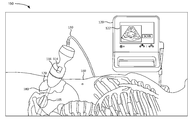
도 1a는 본 발명의 실시예에 따른 초음파 시스템(100)을 나타낸 도면이다. 도 1a에 나타낸 바와 같이, 초음파 시스템(100)은 초음파 프로브(110), 베이스 유닛(120) 및 케이블(130)을 포함할 수 있다. 초음파 프로브(100)은 특정 주파수 및/또는 펄스 반복 속도의 초음파 에너지를 생성하고 반사된 초음파 에너지(예를 들어 초음파 에코)를 수신하여 상기 반사된 초음파 에너지를 전기 신호로 변환시키기 위해, 하나 이상의 초음파 변환기를 수용할 수 있다.1A is a view showing an
예를 들어, 일부 실시예에서, 초음파 프로브(100)는 대략적으로 약 2 메가 헤르츠(MHz)에서 대략적으로 10이상의 MHz(예를 들어, 18 MHz)로 확장된 범위의 초음파 신호를 송신하도록 구성될 수 있다. 다른 실시예에서, 초음파 프로브(110)는 다른 범위의 초음파 신호를 송신하도록 구성될 수 있다. 또한, 초음파 프로브(110)는 초음파 변환기의 움직임을 제어하기 위한 하나 이상의 모터를 수용할 수 있다.For example, in some embodiments, the
초음파 프로브(110)는 핸들(112), 트리거(trigger)(114) 및 돔(118)(또는 노즈(nose)로 언급됨)를 포함할 수 있다. 사용자(예를 들어, 의사 등)는 핸들(112)을 통해 초음파 프로브(110)를 잡고 돔(118)에 위치된 하나 이상의 초음파 트랜시버(트랜시버(transceiver)) 및 변환기 초음파 트리거(114)를 눌러 초음파 신호가 환자의 관심영역(예를 들어, 특정 신체 기관, 신체 관절, 혈관 등)을 향하도록 할 수 있다. 예를 들어, 프로브(110)는 환자의 골반 영역 및 환자의 방광위에 위치될 수 있다.The
핸들(112)은 사용자가 환자의 관심 영역에 대해 프로브(110)를 이동할 수 있도록 한다. 환자의 관심 영역이 스캔될 때, 돔(118)이 환자 신체의 표면 부분과 접촉하는 동안 트리거(114)의 활성은 선택된 해부학적 부분의 초음파 스캔을 개시한다. 일부 실시예에서, 트리거(114)는 토글 스위치(116)를 포함할 수 있다. 토글 스위치(116)은 초음파 시스템(100)의 조준 모드 시, 다른 조준 평면 사이, 다른 스캐닝 모드 사이, 다른 이미징 모드 사이 등을 토글링하기 위해 사용될 수 있다. 다른 실시예에서, 트리거(1140)는 개별의토글 스위치(116)를 포함하지 않을 수 있고, 트리거(114)는 다른 조준 평면, 스캐닝 모드, 및/또는 이미징 모드 사이를 토글링하기 위해 사용될 수 있다.The
또 다른 실시예에서, 토글 스위치(116)는 초음파 프로브(110)의 다른 위치에 배치될 수 있고, 및/또는 베이스 유닛(120)상에 위치될 수 있다. 또 다른 실시예에서, 토글링 기능은 베이스 유닛(120)의 디스플레이상의 터치 스크린 및/또는 마이크와 같은 다른 유형의 제어를 통해(예를 들어, 음성 명령을 통해) 실행될 수 있다.In another embodiment, the
돔(118)은 하나 이상의 초음파 변환기를 둘러쌀 수 있고, 해부학적 부분에 적절한 음향 임피던스 정합을 제공하고, 및/또는 초음파 에너지가 상기 해부학적 부분으로 투영될 때 정확하게 초점이 맞도록 하는 재료로부터 형성될 수 있다. 돔(118)은 또한, 초음파 신호를 송신 및 수신하기 위한 송신기 및 수신기를 포함하는 트랜시버 전기 회로망을 포함할 수 있다. 프로브(110)는 케이블(130)과 같은 유선 연결을 통해 베이스 유닛(120)과 통신할 수 있다. 다른 실시예에서, 프로브(110)는 무선 연결(예를 들어, 블루투스, 와이파이 등)을 통해 베이스 유닛(120)과 통신할 수 있다.The
베이스 유닛(120)은 스캔된 해부학적 영역의 이미지를 생성하기 위해 프로브(110)에 의해 수신된 반사된 초음파 에너지를 처리하도록 구성된 하나 이상의 프로세서 또는 프로세스 로직을 수용하고 포함할 수 있다. 또한, 베이스 유닛(120)은 사용자가 초음파 스캔으로부터 이미지를 볼 수 있도록 하고, 및/또는 프로브(110)의 동작 중, 사용자에 대한 동작상 상호작용을 가능하게 하는 디스플레이(122)를 포함할 수 있다. 예를 들어, 디스플레이(122)는 액정 디스플레이(liquid crystal display, LCD), 발광 다이오드(light emitting diode, LED), 터치스크린 및/또는, 문자 및/또는 이미지 데이터를 사용자에게 제공하는 다른 유형의 디스플레이와 같은 출력 디스플레이/스크린을 포함할 수 있다.
예를 들어, 디스플레이(122)는 환자의 선택된 해부학적 부분에 대해 프로브(110)를 위치시키기 위한 명령을 제공할 수 있다. 대안적으로, 초음파 프로브(110)는 초음파 프로브(110)를 위치시키기 위한 명령을 제공하는 (예를 들어, 핸들(112)에) 작은 디스플레이를 포함할 수 있다. 디스플레이(122)는 또한, 선택된 해부학적 영역의 2차원 또는 3차원 이미지를 표시할 수 있다. For example, the
일부 실시예에서, 디스플레이(122)는 사용자가 초음파 스캔과 관련된 다양한 특징을 선택하도록 하는 그래픽 사용자 인터페이스(graphical 사용자 인터페이스(user interface), GUI)를 포함할 수 있다. 예를 들어, 디스플레이(122)는 프로브(110)를 위한 조준 모드를 선택하기 위해, 및/또는 프로브(110)가 환자의 관심영역에 대해 성공적으로 배치된 이후 3D 스캔을 개시하기 위해, 선택 항목(예를 들어, 드롭다운 메뉴 항목, 체크박스 등)을 포함할 수 있다. In some embodiments,
또한, 디스플레이(122)는 B-모드 이미지, P-모드 이미지, 분할 맵 모드 이미지, 도플러 초음파 이미지, 고조파 모드 이미지, M-모드 이미지 및/또는 다른 유형의 초음파 이미지와 같은 획득될 특정 유형의 초음파 이미지를 선택하기 위한 선택 항목을 포함할 수 있다.Also, the
또한, 디스플레이(122)는 조준 모드 평면, 스캐닝 모드 및 이미징 모드 중 하나 이상을 선택하기 위한 선택 항목을 포함할 수 있다. 또한, 디스플레이(122)는 선택된 조준 모드 평면, 스캐닝 모드 및/또는 이미징 모드 사이에서 수동적으로 또는 자동적으로 토글링할지 여부를 선택하기 위한 선택 항목을 포함할 수 있다.Also, the
도 1b는 본 발명의 실시예에 따른 초음파 시스템(110)의 예시적인 환경(150)을 나타낸 도면이다. 환경(150)은 환자(160)에 대한 초음파 시스템(100)의 동작을 나타낸다. 도 1b에 나타낸 바와 같이, 환자(160)는 환자의 관심 영역이 스캔될 수 있도록 위치될 수 있다. 예를 들어, 관심 영역이 환자의 방광(165)에 해당된다고 가정할 수 있다. 방광(165)을 스캔하기 위해, 초음파 프로브(110)는 스캔될 해부학적 부분에 근접한 환자(160)의 표면 부분에 대해 위치될 수 있다. 사용자는 돔(1178)이 피부에 대해 배치될 때, 음향 임피던스 정합을 제공하기 위해 방광(165) 영역의 환자(160)의 피부에 음향 젤(170)(또는 겔 패드)를 적용할 수 있다.1B is a diagram illustrating an
사용자는 베이스 유닛(120)을 통해 (예를 들어, 디스플레이(122)상의 조준 모드 버튼, 메뉴 항목을 선택함으로써, 음성 명령을 말함으로써 등을 통해) 조준 모드를 선택할 수 있다. 또한, 베이스 유닛(120)이 (예를 들어, 초음파 프로브(110)의 가속도 및/또는 자이로스코프를 통해) 초음파 프로브(110)의 움직임을 검출할 때, 또는 초음파 프로브가 음성 젤(170) 또는 환자의 피부(160)를 접촉할 때 자동적으로 조준 모드가 선택될 수 있다. 초음파 프로브(110)는 방광으로 초음파 신호(180)를 송신할 수 있고, 반사된 초음파 신호를 수신할 수 있다. 상기 반사된 초음파 신호는 디스플레이(122)상에 표시되는 이미지로 처리될 수 있다. The user may select the aiming mode through the base unit 120 (eg, by selecting an aiming mode button on the
일부 실시예에서, 사용자는 조준 모드 평면, 스캐닝 모드, 및/또는 이미징 모드 중 하나 이상을 선택할 수 있다. 다른 실시예에서, 조준 모드 평면, 스캐닝 모드 및/또는 이미징 모드 중 하나 이상은 사용자 입력없이 자동적으로 선택될 수 있다. 일부 실시예에서 디스플레이(122)는 사용자 입력없이 및/또는 사용자가 초음파 프로브(110)의 위치를 변경하지 않아도 선택된 조준 모드 평면, 스캐닝 모드 및/또는 이미징 모드 사이를 자동적으로 토글링할 수 있다.In some embodiments, the user can select one or more of aiming mode plane, scanning mode, and / or imaging mode. In other embodiments, one or more of the aiming mode plane, scanning mode and / or imaging mode may be automatically selected without user input. In some embodiments, the
다른 실시예에서, 사용자는 토글 스위치(116)을 사용하여 선택된 조준 모드, 스캐닝 모드, 및/또는 이미징 모드 사이를 토글링할 수 있다. 또 다른 실시예에서, 선택된 조준 모드 평면, 스캐닝 모드 및/또는 이미징 모드 중 하나 이상은 디스플레이(122)상에 동시에 표시될 수 있다. 사용자는 사용자가 초음파 프로브의 방광(165)위에서의 위치에 대해 만족할 때까지 디스플레이(122)상에 표시된 정보를 기반으로 초음파 프로브(110)의 위치를 조정할 수 있다. 이후 사용자는 트리거(114)를 누르거나 디스플레이(122)상의 스캔 버튼을 누르거나, 음성 명령을 말하거나, 및/또는 또 다른 유형의 스캔 활성 기술을 통해 3D 스캔을 활성화할 수 있다.In other embodiments, the user can toggle between the selected aiming mode, scanning mode, and / or imaging mode using
비록 도1a 및 1b가 초음파 시스템(100)의 예시적인 구성 요소를 나타내지만, 다른 실시예에서, 초음파 시스템(100)은 도 1a 및 1b에 도시된 것보다 적은 구성요소, 다른 구성 요소, 추가 구성 요소 또는 다르게 배열된 구성 요소를 포함할 수 있다. 추가적으로 또는 대안적으로, 초음파 시스템(100)의 하나 이상의 구성 요소는 초음파 시스템(100)의 하나 이상의 구성 요소에 의해 수행되는 것으로 설명된 하나 이상의 작업을 수행할 수 있다. Although FIGS. 1A and 1B represent exemplary components of the
예를 들어, 다른 실시예에서, 초음파 프로브(110)는 초음파 프로브(110)내에 수용되고 하나 이상의 초음파 변환기를 실시가능하도록 제어하고 반사된 초음파 에너지를 처리하여 초음파 이미지를 생성하도록 구성된 마이크로프로세서를 포함하는 자급식 장치(self-contained device)에 부합될 수 있다. 따라서, 초음파 프로브(110)상의 디스플레이는 생성된 이미지를 표시하고 및/또는 초음파 프로브(110)의 동작과 관련된 다른 정보를 나타내기 위해 사용될 수 있다. 또 다른 실시예에서, 초음파 프로브(110)는 초음파 프로브의 동작을 적어도 부분적으로 제어하는 소프트웨어 및/또는 초음파 프로브(100)로부터 수신한 정보를 처리하여 초음파 이미지를 생성하기 위한 소프트 웨어를 포함하는 랩탑, 태블릿 및/또는 데스크탑 컴퓨터와 같은 범용 컴퓨터에 (유선 또는 무선 연결을 통해) 연결될 수 있다.For example, in other embodiments, the
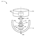
도 2A는 본 발명의 제 1 실시예에 따른 초음파 프로브(110)를 나타낸 도면이다. 도 2A에 나타낸 바와 같이, 초음파 프로브(110)은 2개의 회전 모터에 연결된 단일 변환기 요소를 포함할 수 있다. 상기 실시예에서, 초음파 프로브(110)는 돔(118)에 연결되는 베이스(210), 세타 모터(220), 회전축(230), 파이 모터(240), 및 변화기(260)를 갖는 변환기 버킷(250)을 포함할 수 있다. 세타 모터(220), 파이 모터(240) 및 변환기(260)는 캐이블(130)(도 2A에 미도시)를 통해 베이스 유닛(120)에 세타 모터(220), 파이 모터(240) 및/도는 변환기(260)를 전기적으로 연결하는 유선 또는 무선 전기 연결부를 포함할 수 있다. 2A is a view showing an
베이스(210)는 세타 모터(220)를 수용할 수 있고, 초음파 프로브(110)에 구조적 지지를 제공할 수 있다. 베이스(210)는 돔(118)과 연결될 수 있고, 외부 환경으로부터 초음파 프로브(110)의 구성을 보호하기 위해 돔(118)으로 밀봉 형성할 수 있다. 세타 모터(220)는 본 명세서에서 세타(θ) 회전 평면(225)으로 지칭되는 수직축 중심으로 회전함으로써, 변환기(260)에 대해 길이 방향에 있는 베이스(210)에 대해 회전축(230)을 회전시킬 수 있다. 회전축(230)은 샤프트(235)에 끝단이 있을 수 있고, 파이 모터(240)는 샤프트(235)상에 장착될 수 있다. 파이 모터(240)는 본 명세서에서 파이(Φ) 회전 평면(245)으로 지칭되는 수평 축 중심으로 세타 회전 평면(225)에 대해 직교하는 축 주위를 회전할 수 있다. 변환기 버킷(250)은 파이 모터(240)에 장착될 수 있고, 파이 모터(240)와 함께 움직일 수 있다.The base 210 can accommodate
변환기(260)은 변환기 버킷(250)에 장착될 수 있다. 변환기(260)는 압전 변환기, 용량성 변환기, 및/또는 또 다른 유형의 초음파 변환기를 포함할 수 있다. 변환기(260)와 관련된 트랜시버 회로에 따라, 변환기(260)는 전기 신호를 특정 초음파 주파수 또는 초음파 추파수 범위에서의 초음파 신호로 전환할 수 있고, 반사된 초음파 신호(예를 들어, 에코 등)를 수신할 수 있고, 수신된 초음파 신호를 전기 신호로 전환할 수 있다. 변환기(260)는 초음파 신호를 변환기(260)의 표면에 실질적으로 수직한 신호 방향(265)으로 초음파 신호를 송신 및 수신할 수 있다. The
신호 방향(265)는 파이 모터(240)의 움직임에 의해 제어될 수 있고, 파이 모터는 세타 모터(220)에 의해 제어될 수 있다. 예를 들어, 파이 모터(240)는 180도 미만의 각도로 앞 뒤로 회전하여 특정 평면에 대한 초음파 이미지 데이터를 생성할 수 있고, 세타 모터(220)는 다른 평면에 대한 초음파 이미지 데이터를 획득하기 위해 특정 위치로 회전할 수 있다.The
조준 모드에서, 특정 조준 평면에 대한 초음파 이미지 데이터를 획득하기 위해 파이 모터(240)가 앞뒤로 회전하는 동안, 세타 모터(220)는 정지 상태로 유지될 수 있다. 조준 모드에서, 세타 모터(220)는 다중 조준 평면 사이를 앞뒤로 움직일 수 있고, 파이 모터(240)는 초음파 이미지 데이터를 획득하기 위해 앞뒤로 회전할 수 있다. 예를 들어, 조준 모드 선택 시, 세타 모터(220)는 2개의 직교하는 평면 사이에서 뒤로 이동할 수 있다. 또 다른 예로, 세타 모터(220)는 조준 모드시, 3개의 평면을 통해 120도씩 순차적으로 회전할 수 있다.In the aiming mode, the
3D 스캔 모드에서, 세타 모터(220)는 관심 영역의 완전한 3D 스캔을 획득하기 위해 한 세트 이상의 평면을 순환할 수 있다. 평면 세트들 중 특정 평면 각각에서, 파이 모터(240)는 상기 특정 평면에 대한 B-모드 이미지 데이터를 획득하기 위해 회전할 수 있다. 세타 모터(220) 및 파이 모터(240)의 움직임은 3D 스캔 모터 내에서 인터레이스(interlace)될 수 있다. 예를 들어, 파이 모터(240)의 제 1 방향으로의 움직임은 세타 모터(220)의 제 1 평면에서 제 2 평면으로의 움직임에 의해 이어질 수 있고, 상기 제 1 방향과 반대인 제 2 방향으로의 파이 모터(240)의 움직임에 의해 이어질 수 있고, 세타 모터(220)의 제 2 평면에서 제 3 평면 등으로의 움직임에 의해 이어질 수 있다. 이러한 인터레이스 움직임을 통해 초음파 프로브(110)는 매끄러운 연속 체적 스캐닝을 얻고, 스캔 데이터를 획득하는 속도를 향상시킬 수 있다.In 3D scan mode,
도 2b는 본 발명의 제 2 실시예에 따른 초음파 프로브(110)를 나타낸 도면이다. 도 2b에 나타낸 바와 같이, 초음파 프로브(110)는 회전 모터와 연결된 1차원(1D) 변환기 요소 어레이를 포함할 수 있다. 상기 실시예에서, 초음파 프로브(110)는 돔(118)에 연결되는 베이스(210), 세타 모터(220), 회전축(230) 및 1D 변환기 어레이(275)를 갖는 변환기 버킷(270)을 포함할 수 있다. 세타 모터(220) 및/또는 1D 변환기 어레이(275)는 케이블(130)(도2b에 미도시)을 통해 베이스 유닛(120)에 세타 모터(220) 및/또는 1D 변환기 어레이(275)를 전기적으로 연결하는 유선 또는 무선 전기 연결부를 포함할 수 있다.2B is a view showing an
베이스(210)은 세타 모터(220) 를 수용할 수 있고, 초음파 프로브(110)에 구조적 지지를 제공할 수 있다. 베이스(210)은 돔(118)에 연결될 수 있고, 외부 환경으로부터 초음파 프로브(110)의 구성을 보호하기 위해 돔(118)으로 밀봉 형성할 수 있다. 세타 모터(220)는 세타 회전 평면(225)을 중심으로 회전시킴으로써, 1D 변환기 어레이(275)에 대한 길이 방향에 있는 베이스(210)에 대해 회전축(230)을 회전시킬 수 있다. 회전축(230)은 변환기 버킷(270) 내에 끝단이 있을 수 있다.The base 210 can accommodate
1D 변환기 어레이(275)는 변환기 버킷(270)에 장착될 수 있다. 1D 변환기 어레이(275)는 압전 변환기, 용량형 변환기, 및/또는 다른 유형의 초음파 변환기의 곡선형 1D 어레이를 포함할 수 있다. 1D 변환기 어레이(275)는 전기 신호를 특정 초음파 주파수 또는 초음파 주파수 범위의 초음파 신호로 변환시킬 수 있고, 반사된 초음파 신호(예를 들어, 에코 등)를 수신할 수 있고, 수신된 초음파 신호를 전기 신호로 변환시킬 수 있다. 1D 변환기 어레이(275)의 각각의 요소는 도 2b의 부호번호'276'로 기재된 한 세트 방향인 특정 방향으로 초음파 신호를 송신 및 수신할 수 있다. 따라서, 1D 변환기 어레이(275)의 요소들은 함께 특성 평면에 대한 초음파 이미지 데이터를 생성할 수 있다.The
조준 모드에서, 1D 변환기 어레이(275)가 특정 조준 평면에 대한 초음파 이미지를 얻는 동안 세타 모터(220)는 정지상태로 유지될 수 있다. 상기 조준 모드에서, 세타 모터(220)는 다중 조준 평몇 사이에서 앞뒤로 움직일 수 있고, 1D 변환기 어레이(275)는 각각의 조준 평면에서 초음파 이미지 데이터를 획득할 수 있다. 일 예로, 세타 모터(220)는 조준 모드가 선택되는 동안 2개의 직교하는 평면 사이에서 뒤로 움직일 수 있다. 또 다른 예로, 세타 모터(220)는 서로 120도의 각도로 이격 위치하는 3개의 평면을 통해 순차적으로 회전할 수 있다. 3D 스캔 모드에서, 세타 모터(220)는 관심 영역의 완전한 3D 스캔을 얻기 위해 한 세트 이상의 평면을 순환할 수 있다. 상기 세트의 평면들 중 특정 평면에서, 1D 변환기 어레이(275)는 특정 평면에 대한 초음파 이미지를 획득할 수 있다. In aiming mode,
도2c는 본 발명의 제 3 실시예에 따른 초음파 프로브(110)를 나타낸 도면이다. 도 1에 나타낸 바와 같이, 초음파 프로브(110)는 2차원(2D)의 변환기 요소 어레이를 포함할 수 있다. 상기 실시예에서, 초음파 프로브(110)는 베이스(210), 회전축(230) 및 2D 변환기 어레이(285)를 갖는 변환기 버킷(280)을 포함할 수 있다. 2D 변환기 어레이(285)는 케이블(130)(도2c에 미도시)을 통해 베이스 유닛(120)에 2D 변환기 어레이(285)를 전기적으로 연결하는 유선 또는 무선 전기 연결부를 포함할 수 있다.2C is a view showing an
베이스(210)는 초음파 프로브(110) 및 고정 회전축(230)에 구조적 지지를 제공할 수 있다. 회전축(230)은 변환기 버킷(280) 내에 끝단이 있을 수 있다. 2D 변환기 어레이(285)는 변환기 버킷(280)에 장착될 수 있다. 2D 변환기 어레이(285)는 압전 변환기, 용량형 변환기, 및/도는 다른 유형의 초음파 변환기의 2D어레이를 포함할 수 있다. 2D 변환기 어레이(285)는 전기 신호를 특정 초음파 주파수 또는 초음파 주파수 범위의 초음파 신호로 변환시킬 수 있고, 반사된 초음파 신호(예를 들어, 에코 등)을 수신할 수 있고, 수신된 초음파 신호를 전기 신호로 변환시킬 수 있다. 2D 변환기 어레이(285)의 각각의 요소는 도 2c에 부호번호'290'으로 기재된 한 세트 방향의 특정 방향으로 초음파 신호를 송신 및 수신할 수 있다. 따라서, 2D 변환기 어레이(285)의 요소들은 함께 3D 초음파 스캔을 생성하기 위한 다중 평면에 대한 초음파 이미지 데이터를 생성할 수 있다. 즉, 2D 변환기 어레이(285)는 초음파 빔이 특정 방향으로 기울어지도록 전기적으로 조절될 수 있다. The base 210 may provide structural support to the
조준 모드에서, 2D 변환기 어레이(285)는 하나 이상의 선택된 조준 평면에 대한 초음파 이미지 데이터를 획득할 수 있다. 특정적으로 선택된 조준 평면에 대해, 2D 변환기 어레이(285)의 변환기 요소의 선형의 1D 세트는 상기 특정적으로 선택된 조준 평면에 대한 초음파 이미지를 생성하도록 선택될 수 있다.In aiming mode,
예를 들어, 2개의 변환기의 1D 세트는 2개의 직교 평면에 대해 선택될 수 있고, 2개의 직교 평면의 초음파 이미지를 획득하는 것 사이에서 교번할 수 있다. 대안적으로, 상기 2개의 직교 평면에 대한 초음파 이미지는 실질적으로 동시에 획득될 수 있다. 또 다른 예로, 2D 변환기 어레이(285)는 서로로부터 120도로 이격하여 위치하는 3개의 평면을 통해 순환할 수 있고, 2D 변환기 어레이(285)로부터 변환기 요소의 1D 세트의 3세트는 상기 3개의 평면에 대한 초음파 이미지를 획득할 수 있다. 3D 스캔 모드에서, 2D 변환기 어레이(385)는 관심영역의 완전한 3D 스캔을 획득하기 위해 변환기 요소의 1D 세트의 세트를 통해 1회 이상 순환할 수 있다. 대안적으로, 2D 변환기 어레이(285)의 변환기 요소의 1D 세트의 다중 세트, 또는 심지어 변환기 요소의 모든 세트는 관심 영역의 완전한 3D 스캔을 획득하기 위해 실질적으로 동시에 활성화될 수 있다.For example, a 1D set of two transducers can be selected for two orthogonal planes, alternating between obtaining ultrasound images of two orthogonal planes. Alternatively, the ultrasound images for the two orthogonal planes can be obtained substantially simultaneously. As another example, the
도 2a, 2b 및 3c는 초음파 프로브(110)의 예시이며, 다른 실시예에서, 초음파 프로브(110)는 도 2a, 2b 및 3c에 도시된 것보다 적은 구성, 다른 구성, 추가적 구성 또는 다르게 배열된 구성을 포함할 수 있다. 추가적으로 또는 대안적으로 초음파 프로브(110)의 하나 이상의 구성이 초음파 프로브(110)의 하나 이상의 구성에 의해 수행되는 것으로 설명된 하나 이상의 작업을 수행할 수 있다.2A, 2B, and 3C are examples of
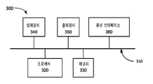
도 3은 본 발명의 실시예에 따른 장치(300)의 예시적인 구성 요소를 나타낸 도면이다. 초음파 프로브(110) 및/또는 베이스 유닛(120) 각각은 하나 이상의 장치(300)를 포함할 수 있다. 도 3에 나타낸 바와 같이,장치(300)는 버스(310), 프로세서(320), 메모리(330), 입력 장치(340), 출력 장치(350) 및 통신 인터페이스(360)를 포함할 수 있다.3 is a diagram showing exemplary components of an
버스(310)는 장치(300)의 구성요소 사이의 통신을 허용하는 경로를 포함할 수 있다. 프로세서(320)는 명령을 해석 및 실행하는 임의의 유형의 단일 코어 프로세서, 다중 코어 프로세서, 마이크로 프로세서, 래치(latch) 기반 프로세서 및/또는 프로세싱 로직(또는 프로세서, 마이크로 프로세서, 마이크로 프로세서, 및/또는 프로세싱 로직의 집합)를 포함할 수 있다.The
다른 실시예에서, 프로세서(320)는 주문형 집적회로(application-specific integrated circuit, ASIC), 필드 프로그래머블 게이트 어레이(field-programmable gate array, FPGA), 및/또는 다른 유형의 집적 회로 또는 프로세싱 로직을 포함할 수 있다.In other embodiments, the
메모리(330)는 프로세서(320)에 의한 실행을 위해 정보를 저장 및/또는 명령할 수 있는 임의의 유형의 동적 저장 장치, 및/또는 프로세서에 의한 사용을 위해 정보를 저장할 수 있는 임의의 유형의 비휘발성 저장 장치를 포함할 수 있다. 예를 들어, 메모리(330)는 랜덤 엑세스 메모리(random access memory, RAM) 또는 다른 유형의 동적 저장 장치, 읽기 전용 메모리(read-only memory, ROM) 장치 또는 다른 유형의 정적 저장 장치, 내용 주소화 메모리(content addressable memory, CAM) 장치, 자력 및/또는 광학 레코팅 메모리 장치 및 이에 부합되는 장치(예를 드어, 하드 디스크 드라이브, 광학 드라이브 등) 및/또는 플래쉬 메모리와 같이 제거가능한 형태의 메모리를 포함할 수 있다.The
입력 장치(340)는 작업자가 장치(300)에 정보를 입력하도록 할 수 있다. 입력 장치(340)는 예를 들어, 키보드, 마우스, 펜, 마이크, 원격조절기, 오디오 캡쳐 장치, 이미지 및/또는 비디어 캡쳐 장치, 터치 스크린 디스플레이, 및/또는 다른 유형의 입력 장치를 포함할 수 있다. 일부 실시예에서, 장치(300)는 원격으로 관리될 수 있고, 입력 장치(340)를 포함하지 않을 수 있다. 즉, 장치(300)는 “헤드리스(headless)”될 수 있고, 예를 들어, 키보드를 포함하지 않을 수 있다. The
출력 장치(350)는 정보를 장치(300)의 작업자에게 출력할 수 있다. 출력 장치(350)는 디스플레이, 프린터, 스피커, 및/또는 다른 유형의 출력 장치를 포함할 수 있다. 예를 들어, 장치(300)는 내용을 고객에서 표시하는 액정 디스플레이(liquid-crystal display, LCD)일 수 있다. 일부 실시예에서, 장치(300)는 원격으로 관리될 수 있고 출력 장치(350)를 포함하지 않을 수 있다. 즉, 장치(300)는 “헤드리스”될 수 있고, 예를 들어, 디스플레이를 포함하지 않을 수 있다.The
통신 인터페이스(360)는 장치(300)를 다른 장치와 통신 가능하게 하는 트랜시버, 및/또는 무선 통신(예를 들어, 라디어 주파수, 적외선 및/또는 가시광의 광학 등) 또는 유선 통신(예를 들어, 전도성 와이어, 트위스트되어 있는 페어 캐이블, 동축 캐이블, 전송 라인, 광섬유 캐이블, 및/또는 도파관 등) 또는 유무선 통신의 조합을 통한 시스템를 포함할 수 있다. 통신 인터페이스(360)는 기저 대역 신호를 라이도 주파수(RF) 신호로 변환하는 송신기(transmitter) 및 RF 신호를 기저 대역 신호로 변환하는 수신기(receiver)를 포함할 수 있다. 통신 인터페이스(360)는 RF 신호를 송신 및 수신하기 위한 안테나와 연결될 수 있다.The
통신 인터에피스(360)는 입력 및/또는 출력 포트, 입력 및/또는 출력 시스템, 및/또는 다른 장치로의 데이터의 전송을 용이하도록 하는 다른 입력 및 출력 구성요소를 포함하는 논리 구성 요소를 포함할 수 있다. 예를 들어, 통신 인터페이스(360)는 유선 통신을 위한 네트워크 인터페이스 카드(예를 들어, 이더넷(Ethernet) 카드) 및/또는 무선 통신을 위한 무선 네트워크 인터페이스(예를 들어, 와이파이(WiFi)) 카드를 포함할 수 있다. 또한, 통신 인터페이스(360)는 블루투스™ 무선 인터페이스를 통해 통신하기 위한 유니버셜 시리얼 버스(universal serial bus, USB) 포트, 라이도-주파수 식별(radio-frequency identification, RFID) 인터페이스, 근거리 무선 통신(near-field communications, NFC) 무선 인터페이스 및/또는 하나의 형태에서 다른 형태로 데이터를 변환하는 다른 유형의 인터페이스를 포함할 수 있다.
이하에 상세히 설명된 바와 같이, 장치(300)는 조준 모드 동안 관심 영역의 다중 평면 시각화와 관련된 어떤 동작을 수행할 수 있다. 장치(300)는 메모리(300)와 같은 컴퓨터 판독가능 매체(computer-readable medium)에 포함되어 있는 소프트웨어 명령을 실행하는 프로세서(320)에 대한 응답으로, 이러한 동작을 수행할 수 있다. 컴퓨터 판동가능 매체는 비일시적 메모리 장치(non-transitory memory device)로서 정의될 수 있다. 메모리 장치는 하나의 물리적 메모리 장치로 구현되거나 또는 다중 물리적 메모리 장치로 분산될 수 있다. 상기 소프트웨어 명령은 다른 컴퓨터 판독가능 매체 또는 다른 장치로부터 메모리(330)로 판독될 수 있다.As described in detail below, the
메모리(300)에 포함된 상기 소프트 웨어 명령은 프로세서(320)로 하여금 본 명세서에서 설명된 프로세스를 수행하도록 할 수 있다. 대안적으로, 컴퓨터에 내장된 전기회로망은 본 명세서에서 설명된 프로세서를 수행하기 위한 소프트웨어 명령을 대체하여 사용될 수 있고, 또는 상기 소프트웨어 명령과 결합되어 사용될 수 있다. 따라서, 본 명세서에 설명된 실시예는 하드웨어 전기 회로망 및 소프트웨어의 어느 특정 결합에 제한되지 않는다.The software instructions included in the
도 3은 장치의 예시적인 구성요소를 나타내지만, 다른 실시예에서, 장치(300)는 도3에 도시된 것보다 적은 구성 요소, 다른 구성 요소, 또는 다르게 배열된 구성 요소를 포함할 수 있다. 추가적으로 또는 대안적으로 장치의 하나 이상의 구성요소는 장치(300)의 하나 이상의 구성 요소에 의해 수행되는 것으로 설명된 하나 이상의 작업을 수행할 수 있다.3 shows exemplary components of the device, in other embodiments, the
도 4는 초음파 시스템(100)의 예시적인 기능적 구성 요소를 나타낸 것이다. 상기 초음파 시스템(100)의 기능적 구성 요소는 예를 들어, 메모리(330)로부터의 명령을 실행하는 프로세서(320)를 통해 실시될 수 있다. 대안적으로, 초음파 시트템(100)의 기능적 구성 요소의 일부 또는 전부는 컴퓨터에 내장된 전기 회로망을 통해 실시될 수 있다. 도 4에 나타낸 바와 같이, 초음파 시스템(100)은 사용자 인터페이스(410), 조준 모드 매니저(420), 이미지 생성(430), 3D 스캔 매니저(440) 및 데이터 수집기(450)를 포함할 수 있다.4 shows exemplary functional components of the
사용자 인터페이스(410)는 디스플레이(122)를 통해 사용자에게 초음파 이미지를 표시하는 사용자 인터페이스(예를 들어, 그래픽 사용자 인터페이스)를 생성할 수 있다. 또한, 이는 디스플레이(122)와 관련된 터치스크린, 베이스 유닛(120) 및/도는 초음파 프로브(110)상에 위치하는 하나 이상의 컨트롤키, 베이스 유닛(120)에 포함된 마이크, 및/또는 다른 유형의 입력 방법을 통해, 사용자로부터의 선택 및/또는 명령을 수신하도록 구성될 수 있다. 예를 들어, 사용자는 한 유형의 초음파 이미지를 선택할 수 있고, 사용자 인터페이스(410)를 통한 조준 모드는 하나 이상의 조준 모드 평면, 스캐닝 모드 및/또는 이미징 모드를 선택할 수 있고, 및/또는 사용자가 조준 모드 동안 초음파 프로브(110)의 위체 만족할 때 3D 스캔이 수행되도록 선택할 수 있다.The
조준 모드 매니저(420)는 초음파 시스템(100)와 관련된 조준 모드를 관리할 수 있다. 예를 들어, 사용자가 스캔을 수행하도록 선택할 때, 초음파 시스템(100)은 자동적으로 조준 모드를 실행할 수 있다. 다른 예로서, 사용자는 선택 항목을 사용하여 및/또는 특정 명령을 실행함으로써 조준 모드를 선택할 수 있다. The aiming
일부 실시예에서, 조준 모드 매니저(420)는 예를 들어, 3개의 직교 평면과 같은 조준 모드 평면의 디폴트 세트를 선택할 수 있다. 추가적으로 또는 대안적으로, 사용자는 조준 모드 평명, 스캐닝 모드 및/또는 이미징 모드 중 하나 이상을 선택할 수 있다.In some embodiments, aiming
예로서, 사용자는 특정 평면(예를 들어, 시상면, 정면 등)을 지정함으로써, 제 1 조준 모드 평면을 선택할 수 있고, 각각의 추가 평면을 지정함으로써 추가 조준 모드 평면을 선택할 수 있다. 또 다른 예로, 사용자는 첫번째 스캐닝 평면을 지정함으로써 제 1스캐닝 평면을, 두번째 스캐닝 평면을 지정함으로써 제2 스캐닝 평면을 선택할 수 있다. 또 다른 예로, 사용자는 제 1 이미징 모드 및 제2 이미징 모드를 선택할 수 있다.As an example, the user can select a first aiming mode plane by specifying a specific plane (eg, sagittal, frontal, etc.) and a further aiming mode plane by specifying each additional plane. As another example, the user may select the first scanning plane by specifying the first scanning plane, and the second scanning plane by specifying the second scanning plane. As another example, the user may select a first imaging mode and a second imaging mode.
조준 모드 평면은 이름을 통해 선택될 수 있고, 각도 오프셋(예를 들어, 제2 평면은 제 1 평면+90도 등)을 통해 선택될 수 있고, 조준 모드 평면 세트(예를 들어, 2개의 직교 평면, 60도로 분할된 3개의 평면, 45도로 분할된 4개의 평면, 45도 분할된 2개의 평면 및 상기 2개의 평면 사이의 각도를 이등분하는 평면에 직교하는 3개의 평면 등)을 선택함으로써 선택될 수 있고, 디스플레이(122)의 터치스크린상의 관심영역의 그래픽 표현 주위에 도시된 원을 가로지르는 각각의 평면을 도시 또는 선택한거나, 및/또는 다른 기술을 사용함으로써 선택될 수 있다.The aiming mode plane may be selected by name, and may be selected through an angular offset (eg, the second plane is the first plane + 90 degrees, etc.), and the aiming mode plane set (eg, two orthogonal) Plane, three planes divided by 60 degrees, four planes divided by 45 degrees, two planes divided by 45 degrees, and three planes orthogonal to the plane bisecting the angle between the two planes, etc.) Can be, or can be selected by showing or selecting each plane across the circle shown around the graphical representation of the region of interest on the touch screen of the
조준 모드 매니저(420)는 이미지 생성기(430)에게 특정 유형의 초음파 이미지, 예를 들어 B-모드 초음파 이미지, P-모드 초음파 이미지, 도플러 초음파 이미지, 분할맵 모드 초음파 이미지, 고조파 모드 초음파 이미지, M-모드 초음파 이미지, 및/또는 다른 유형의 초음파 이미지를 사용하여 선택된 조준 모드 평면에 대한 초음파 이미지를 생성하도록 지시할 수 있다.The aiming
일부 실시예에서, 조준 모드 매니저(420)는 선택된 조준 모드 평면, 스캐닝 모드 및/또는 이미징 모드 사이를 자동적으로 토글링할 수 있다. 또한 디스플레이(122)상에 선택된 조준 모드 평면 스캐닝 모드 및/또는 이미징 모드와 관련된 초음파 이미지를 표시할 수 있다. 다른 조준 모드 평면, 스캐닝 모드 및/또는 이미징 모드와 관련된 초음파 이미지는 동시에 표시될 수 있고, 또는 디스플레이(122)는 상기 다른 조준 모드 평면, 스캐닝 모드 및/또는 이미징 모드 이미지를 표시하는 것을 통해 토글링할 수 있다.In some embodiments, the aiming
다른 실시예에서, 사용자는 토글 스위치(116)를 누름으로써, 및/또는 상기 다른 조준 모드 평면, 스캐닝 모드 및/도는 이미징 모드 이미지(예를 들어, 디스플레이의 터치스크린상의 토글 버튼을 누름으로써, 명령을 말함으로써 등) 사이를 토글하도록하는 다른 선택을 통해, 상기 다른 조준 모드 평면, 스캐닝 모드 및/또는 이미징 모드 이미지 사이를 토글링할 수 있다.In another embodiment, the user can press the
이미지 생성기(430)는 특정 평면에 초음파 이미지를 생성할 수 있다. 예를 들어, 이미지 생성기(430)는 특정 평면(예를 들어, 세타 모터(220)의 특정 위치)으로 이동하여 상기 특정 평면의 특정 유형의 초음파 이미지를 생성하도록, (예를 들어, 파이 모터(240) 및 변환기(260)를 사용하여) 데이터 수집기에게 특정 유형의 초음파 이미지를 얻도록 명령할 수 있다.The
3D 스캔 매니저(440)는 환자 신체의 관심 영역의 3D 스캔을 생성할 수 있다. 예를 들어, 사용자가 3D 스캔을 수행하도록 선택한 것에 대한 응답으로, 3D 스캔 매니저(440)는 이미지 생성기(430)에게 특정 순서로 특정 세트의 평면에 대한 초음파 이미지르 생성하도록 명령할 수 있다. 일부 실시예에서, 상기 3D 스캔은 세타 모터(2230) 및 파이 모터(240)의 인터레이스한 움직임으로 실시될 수 있다. 3D 스캔하는 동안 스캔되는 평면의 수(예를 들어, 세타 모터(220)의 다른 위치의 수)는 사용자에 의해 구성 가능힐 수 있다. 예를 들어, 3D 스캔은 30도 마다, 15도 마다, 10도 마다 5도 마다 등으로 평면을 스캔하도록 설정될 수 있다.The
데이터 수집기(450)은 초음파 프로브(110)로부터 초음파 이미지 데이터를 수집하도록 구성될 수 있다. 데이터 수집기(450)는 파이 모터 컨트롤러(460), 세타 모터 컨트롤러(470), 및 변환기 컨트롤러(480)을 포함할 수 있다. 파이 모터 컨트롤러(460)는 파이 모터(240)를 제어할 수 있다. 세타 모터 컨트롤러(470)는 세타 모터를 제어할 수 있다. 변환기 컨트롤러(480)는 변환기(360)(또는 1D 변환기 어레이(275) 또는 2D 변환기 어레이(285))를 제어할 수 있다.The
도 4는 초음파 시스템(100)의 예시적인 구성 요소를 나타내지만, 다른 실시예에서, 초음파 시스템(100)은 도 4에 도시된 것보다 적은 구성 요소, 다른 구성 요소, 추가 구성 요소 또는 다르게 배열된 구성 요소를 포함할 수 있다. 추가적으로 또는 대안적으로, 초음파 시스템(100)의 하나 이상의 구성 요소는 초음파 시스템(100)의 하나 이상의 구성 요소에 의해 수행되는 것으로 셜명된 하나 이상의 작업을 수행할 수 있다.4 shows exemplary components of the
도 5는 본 발명의 실시예에 따라, 조준하는 동안 다중-평면 시각화를 위한 프로세스 흐름도이다. 일부 실시예에서, 도 5의 프로세스는 초음파 시스템(100)에 의해 수행될 수 있다. 일부 실시예에서, 도 5의 일부 또는 전부는 초음파 시스템(100)으로부터 분리된 다른 장치 또는 장치 그룹에 의해 수행될 수 있다. 5 is a process flow diagram for multi-plane visualization during aiming, according to an embodiment of the invention. In some embodiments, the process of FIG. 5 may be performed by
도 5의 프로세스는 조준 모드를 선택하는 단계(510)를 포함할 수 있다. 예를 들어, 사용자가 스캔을 수행하도록 및/또는 초음파 시스템(100)이 켜지도록 선택할 때, 초음파 시스템(100)은 자동적으로 조준 모드를 실행할 수 있다. 다른 예로서, 사용자는 선택 항목을 사용함으로써, 및/또는 특정 명령을 실행함으로써 조준 모드를 선택할 수 있다. 또한, 사용자는 조준 모드 동안 사용할 특정 유형의 초음파 이미지를 선택할 수 있다. 예를 들어, 사용자는 B-모드 초음파 이미지, P-모드 초음파 이미지, 도플러 초음파 이미지, 고조파 모드 초음파 이미지, M-모드 초음파 이미지, 및/또는 다른 유형의 초음파 이미지를 사용하도록 선택할 수 있다. The process of FIG. 5 can include step 510 of selecting an aiming mode. For example, when the user selects to perform a scan and / or the
제 1 조준 모드 평면, 스캐닝 모드, 및/또는 이미징 모드가 선택될 수 있다(520). 또한, 제 1 조준 모드 평면, 스캐닝 모드, 및/또는 이미징 모드는 스캔될 수 있다(530). The first aiming mode plane, scanning mode, and / or imaging mode may be selected (520). Also, the first aiming mode plane, scanning mode, and / or imaging mode may be scanned (530).
일부 실시예에서, 초음파 시스템(100)은 제 1 조준 모드 평면으로 디폴트 평면(예를 들어, 시상면, 횡단면 등), 디폴트 스캐닝 모드(예를 들어, 단일 평면 스캔 등), 및/또는 디폴트 이미징 모드(예를 들어, B-모드 등)를 사용할 수 있다. 다른 실시예에서, 사용자는 평면 리스트로부터 하나의 평면을 선택함으로써, 평면의 이름을 지정함으로써, (예를 들어, 시상면으로부터), 각도 오프셋을 지정함으로써, 디스플레이(122)상에 표시된 관심 영역을 가로지르는 선을 도시하거나 선택함으로써, 및/또는 다른 기술을 사용함으로써 제 1 조준 모드 평면을 선택할 수 있다. 추가적으로 또는 대안적으로, 사용자는 제시된 스캐닝 모드 및/또는 이미징 모드 리스트로부터 스캐닝 모드 및/또는 이미징 모드를 선택함으로써 제 1 스캐닝 모드 및/또는 이미징 모드를 선택할 수 있다. 초음파 시스템(100)은 선택된 제 1 조준 모드, 스캐닝 모드 및/또는 이미징 모드를 디스플레이(122)에서 스캔 및 표시할 수 있다.In some embodiments, the
추가 조준 모드 평면, 스캔 모드 및/또는 이미징 모드가 선택될 수 있다(블록540). 또한, 상기 선택된 추가 조준 모드 평면, 스캐닝 모드, 및/또는 이미징 모드는 스캔될 수 있다(블록 550). 예를 들어, 사용자는 상술된 하나 이상의 기술을 사용하여 추가 조준 모드 평면, 스캐닝 모드 및/또는 이미징 모드를 선택할 수 있고, 초음파 시스템(110)은 사용자가 상기 초음파 프로브(110)의 위치를 변경할 필요없이 디스플레이(122)에 상기 선택된 추가 조준 모드, 스캐닝 모드 및/또는 이미징 모드를 스캔 및 표시할 수 있다. Additional aiming mode planes, scan modes and / or imaging modes may be selected (block 540). Further, the selected additional aiming mode plane, scanning mode, and / or imaging mode may be scanned (block 550). For example, the user can select an additional aiming mode plane, scanning mode and / or imaging mode using one or more of the techniques described above, and the
추가 조준 모드 평면, 스캐닝 모드 및/또는 이미징 모드가 선택되는지에 대해 결정이 수행될 수 있다(블록 560). 예를 들어, 초음파 시스템(100)은 선택된 조준 모드 평면, 스캐닝 모드, 및/또는 이미징 모드 사이를 계속해서 토글링할 수 있고, 사용자는 또 다른 조준 모드 평면, 스캐닝 모드 및/또는 이미징 모드를 선택할 수 있다.A determination can be made as to whether an additional aiming mode plane, scanning mode and / or imaging mode is selected (block 560). For example, the
만약, 추가 조준 모드 평면, 스캐닝 모드, 및/또는 이미징 모드가 선택되었다고 결정되면(블록 560-YES), 프로세싱은 540블록으로 되돌아갈 수 있다. 만약, 추가 조준 모드 평면, 스캐닝 모드, 및.또는 이미징 모드가 선택되지 않으면(블록 560-No), 후속 조준 모드 프로세싱(블록 670)을 진행할건지에 대한 결정이 수행될 수 있다.If it is determined that an additional aiming mode plane, scanning mode, and / or imaging mode has been selected (block 560-YES), processing may return to block 540. If an additional aiming mode plane, scanning mode, and / or imaging mode is not selected (block 560-No), a determination may be made as to whether to proceed to the next aiming mode processing (block 670).
일 예로, 초음파 시스템(100)은 3D 스캠을 수행하도록하는 선택을 결정할 수 있다. 3D 스캔은, 예를 들어, 디스플레이(122)의 터치 스크린 상의 3D스캔 버튼을 선택함으로써, 베이스 유닛(120) 및/또는 초음파 프로브(110)상의 특정 키를 누름으로써, 음성 명령을 말함으로써, 및/도는 다른 기술을 사용함으로써 선탤될 수 있다.As an example, the
또 다른 예로, 초음파 시스템(100)은 예를 들어, 디스플레이(122)상에 제공된 옵션 리스트로부터 니들 가이드를 선택함으로써 사용자가 니들 가이드를 위치시키기 위해 선택했다고 결정할 수 있다. 또 다른 예로, 초음파 시스템(100)은 예를 들어, 디스플레이(122)상에 제공된 옵션 리스트로부터 분석 모드를 선택함으로써, 사용자가 관심 영역을 분석(예를 들어, 기관의 체적 측정, 기관 내 체액량 측정, 관심 영역을 통하는 혈류 측정 등)을 선택했다고 결정할 수 있다. As another example, the
만약, 프로세싱이 후속 조준 모드 프로세싱을 진행하지 않는 것으로 결정되면(블록 570-NO), 상기 선택된 조준 모드 평명, 스캐닝 모드, 및/또는 이미징 모드 사이의 토글링하는 단계가 수행될 수 있다(블록 580).If processing is determined not to proceed with subsequent aiming mode processing (block 570-NO), a step of toggling between the selected aiming mode plainness, scanning mode, and / or imaging mode may be performed (block 580). ).
예를 들어, 초음파 시스템(100)은 상기 3D 스캔이 선택되거나 및/또는 (예를 들어, 초음파 시스템(100)이 유휴 모드(idle mode)에 놓이는 등)다른 모드가 선택될 때까지, 상기 선택된 조준 모드 평면, 스캐닝 모드, 및/또는 이미징 모드 사이를 계속해서 토글링할 수 있다.For example, the
만약, 프로세싱이 3D 스캔이 진행되도록 결정되면(블록 570-YES), 후속 조준 모드 프로세싱이 수행될 수 있다(블록 590). 예를 들어, 사용자가 초음파 프로브(110)의 정렬에 만족한 이후, 조준 모드 동안 다중 조준 모드 평면을 통해 표시된 정보를 기반으로, 사용자는 3D 스캔를 수행하도록 선택할 수 있고, 초음파 시스템(100)은 3D 스캔을 수행할 수 있다.If processing is determined to proceed with the 3D scan (block 570-YES), subsequent aiming mode processing may be performed (block 590). For example, after the user is satisfied with the alignment of the
일부 실시예에서, 초음파 시스템(100)은 후속 조준 프로세싱 동안, 상기 선택된 조준 모드 평면, 스캐닝 모드, 및/또는 이미징 모드 사이를 계속해서 토글링할 수 있다. 예를 들어, 사용자는 니들 가이드 모드를 선택할 수 있다. 이에 응답으로, 초음파 시스템(100)은 사용자가 상기 니들 가이드를 동작하고 초음파 시스템(100)이 상기 선택된 조준 모드 평명, 스캐닝 모드, 및/또는 이미징 모드 사이를 계속해서 토글링하는 동안, 이미지 및/또는 명령을 사용자에게 제공하는 니들 가이드 모드를 실행할 수 있다. In some embodiments, the
또 다른 예로, 초음파 시스템(100)은 기관 또는 체강의 체적을 측정하도록 선택함으로써, 기관 또는 체강 내의 체액량을 측정하도록 선택함으로써, 관심 영역을 통한 혈류를 측정하도록 선택함으로써, 및/또는 다른 유형의 분석을 선택함으로써, 사용자가 관심 영역의 분석을 선택했다고 결정할 수 있다. 이에 응답하여, 초음파 시스템(100)은 시스템(100)이 상기 선택된 조준 모드 평면, 스캐닝 모드 및/또는 이미징 모드 사이를 계속해서 토글링하는 동안, 분석 모드를 실행할 수 있고, 요청된 측정을 수행할 수 있다.As another example, the
도 6은 본 발명의 다른 실시예에 따른, 조준 모드 동안 다중-평면 시각화를 위한 프로세스 흐름도이다. 도 6의 프로세스에서, 초음파 시스템(100)이 활성화될 때 및/또는 조준 모드가 선택될 때, 초음파 시스템(100)은 수동적으로 토글링할 필요 없이, 조준 모드 평면, 스캐닝 모드 및/또는 이미징 모드 중 2개 이상의 사이를 자동적으로 토글링할 수 있다. 일부 실시예에서, 자동 토글링은 디폴트 조준 모드로서 사용될 수 있고, 및/또는 사용자가 환자의 신체에 니들 가이드 및/또는 다른 유형의 의료용 장치를 동작하는 동안 사용될 수 있다. 일부 실시예에서, 도 6의 프로세스는 초음파 시스템(100)에 의해 수행될 수 있다. 다른 실시예에서, 도 6의 프로세스의 일부 또는 전부는 초음파 시스템(100)르보퉈 분리된 또 다른 장치 또는 장치의 그룹에 의해 수행될 수 있다.6 is a process flow diagram for multi-plane visualization during aiming mode, according to another embodiment of the present invention. In the process of FIG. 6, when the
도 6의 프로세스는 조준 모드를 선택하는 단계(블록610)을 포함할 수 있다. 일 예로, 사용자는 스캠이 수행되도록 및/도는 초음파 시스템(100)이 켜지도록 선택할 때, 초음파 시스템(100)은 자동적으로 조준 모드를 실행할 수 있다. 또 다른 예로, 사용자는 선택 항목을 사용하여, 및/또는 디폴트 조준 모드, 니들 가이드 조준 모드, 및/또는 다른 유형의 조준 모드를 선택하는 것과 같이, 특정 명령을 실행함으로써, 특정 조준 모드를 선택할 수 있다. The process of FIG. 6 may include selecting an aiming mode (block 610). For example, when the user selects to perform the scam and / or turn on the
조준 모드 평면, 스캐닝 모드, 및/또는 이미징 모드 중 2개 이상 사이를 토글링하는 단계가 수행될 수 있다(블록 620). 예를 들어, 선택된 조준 모드에 대한 응답으로, 초음파 시스템(100)은 초음파 시스템(100)이 상기 선택된 조준 모드에 있는 동안, 조준 모드 평면, 스캐닝 모드, 및/또는 이미징 모드의 특정 세트 사이를 자동적으로 토글링할 수 있다.Toggling between two or more of the aiming mode plane, scanning mode, and / or imaging mode may be performed (block 620). For example, in response to a selected aiming mode, the
예를 들어, 초음파 시스템(100)은 시상면 및 횡단면과 같은 2개의 직교 평면 사이를 토글링할 수 있다. 또 다른 예로, 초음파 시스템(100)은 선택된 조준 모드에 대한 응답으로, 3개의 평면을 통해 서로 120도씩 순차적으로 회전할 수 있다. 또 다른 예로, 초음파 시스템(100)은 단일 평면 스캔 및 2중 평면 스캔 사이를 토글링할 수 있다.For example, the
또 다른 예로, 초음파 시스템(100)은 B-모드 이미지 및 P-모드 이미지 사이를 토글링할 수 있다. 초음파 시스템(100)은 특정 토글링 속도로, 조준 모드 평면, 스캐닝 모드, 및/도는 이미징 모드의 세트 사이를 토글링할 수 있다. 사용자가 토글링 속도를 증가 또는 감소시킬 수 있도록 사용자에게 선택 객체 및/또는 음성 명령 옵션이 제공될 수 있다. As another example, the
사용자는 상기 조준 모드(블록 630)에 있는 동안, 다른 이미징 모드들 사이를 전환할 수 있다. 예를 들어, 초음파 시스템(100)은 선택 객체 및/또는 음성 명령 옵션을 제공하여, 사용자가 예를 들어, B-모드 초음파 이미지, P-모드 초음파 이미지, 도플러 초음파 이미지, 고조파 모드 초음파 이미지, M-모드 초음파 이미지, 및/또는 다른 유형의 초음파 이미지와 같이, 상기 조준 모드 동안 사용하기 위한 특정 유형의 초음파 이미지를 선택할 수 있도록 한다. 일 예로, 2개의 직교 B-모드 이미지 사이를 자동적으로 토글링하여 니들 삽입을 위한 표적 혈관을 찾기 위해 시도하는 동안, 사용자는 표적 혈관을 보다 효율적으로 찾기 위해 도플러를 켜거가 끄도록 선택할 수 있다.The user can switch between different imaging modes while in the aiming mode (block 630). For example, the
후속 조준 모드 프로세싱을 진행할 것인지 대한 결정이 수행될 수 있다. 예를 들어, 초음파 시스템(100)은 3D 스캔을 수행하도록 선택되었다고 결정할 수 있다. 또 다른 예로, 초음파 시스템(100)은 사용자가 예를 들어, 표적 영역, 예를 들어, 혈관 내로 니들의 성공적인 삽입을 수행한 후, 상기 조준 모드를 종료했다고 결정할 수 있다. 또 다른 예로, 초음파 시스템(100)은 예를 들어, 디스플레이(122)상에 제공된 옵션 리스트로부터 분석 모드 선택을 선택함으로써, 사용자가 (예를 들어, 기관의 체적 측정, 초직 내 유량 측정, 관심 영역을 통한 혈류의 측정 등)관심 영역을 분석하도록 선택했다고 결정할 수 있다. A determination can be made as to whether to proceed to the subsequent aiming mode processing. For example, the
만약, 프로세싱이 후속 조준 모드 프로세싱을 진행하지 않는 것으로 결정되면(블록 640), 조준 모드 평면, 스캔 모드, 및/또는 이미징 모드 중 2개 이상 사이를 자동적으로 토글링하는 단계는 계속해서 수행될 수 있다(블록 620). 만약, 프로세싱이 3D 스캔을 진행하는 것으로 결정(블록 640-YES)되면, 후속 조준 모드 프로세싱이 수행될 수 있다(블록 650).If processing is determined not to proceed with subsequent aiming mode processing (block 640), the step of automatically toggling between two or more of aiming mode plane, scan mode, and / or imaging mode may continue to be performed. Yes (block 620). If processing is determined to proceed with a 3D scan (block 640-YES), subsequent aiming mode processing may be performed (block 650).
일 예로, 사용자가 초음파 프로브(110)의 정렬에 만족한 이후, 조준 모드 동안 상기 조준 모드 평면, 스캐닝 모드, 및.또는 이미징 모드 중 2개 이상을 통해 표시된 정보에 기반하여, 사용자는 3D 스캔의 수행을 선택할 수 있고, 초음파 시스템(100)은 3D 스캔을 수행할 수 있다. 또 다른 예로, 초음파 시스템(100)은 어떠한 추가 프로세싱을 수행하지 않고, 조준 모드를 종료할 수 있다.As an example, after the user is satisfied with the alignment of the
도 7은 본 발명의 일 실시예에 따른 다중-평면 시각화(700)를 나타낸 도면이다. 도 7에 나타낸 바와 같이, 다중 평면 시각화(700)는 환자(260) 기관(165)의 스캔을 포함할 수 있고, 이는 제 1 조준 모드 평면(710) 및 제2 조준 모드 평면(720)을 포함하는 2개의 조준 모드 평면을 포함할 수 있다. 제 1 조준 모드 평면(710)은 횡단면에 부합될 수 있고, 제2 조준 모드 평면(720)은 시상면에 부합될 수 있다. 제 1 조준 모드 평면(710)은 베이스 유닛(120) (도7에 미도시)에, 예를들어, 디스플레이(122)상에, 제 1 초음파 이미지(715)로서 표시될 수 있고, 제2 조준 모드 평면(720)은 베이스 유닛(120)상에 제2 초음파 이미지(725)로서 표시될 수 있다.7 is a diagram illustrating a
도 8은 본 발명의 실시예에 따른 제 1 사용자 인터페이스(800)를 나타낸 도면이다. 도 8에 나타낸 바와 같이, 일부 실시예에서, 제 1 초음파 이미지(715) 및 제 2 초음파 이미지(725)는 실시간 또는 거의 실시간으로 디스플레이(122)상에 함께 표시될 수 있다. 따라서, 초음파 프로브(110)가 제 1 조준 모드 평면(710)을 스캔함에 따라, 제 1초음파 이미지(714)가 새로운 이미지로 리프레쉬될 수 있다. 이후, 초음파 프로브(110)는 제 2 조준 모드 평면(720)을 스캔하고 제2 초음파 이미지(725)가 새로운 이미지로 리프레쉬될 수 있다. 8 is a diagram illustrating a first user interface 800 according to an embodiment of the present invention. 8, in some embodiments, the
도 9는 본 발명의 제2 실시예에 따른 사용자 인터페이스(900)를 나타낸 도면이다. 도 9에 나타낸 바와 같이, 다른 실시예에서, 디스플레이(122)는 특정 시간 간격으로, 또는 사용자가 토글링 스위치(116)(및/또는 초음파 시스템(100)과 관련된 다른 키 또는 버튼)을 누룸에 대한 응답으로, 제 1 초음파 이미지(715) 및 제2 초음파 이미지(725) 사이를 토글링할 수 있다. 다른 실시예에서, 제 1 초음파 이미지(715) 및 제 2 초음파 이미지(725)는 타일형 구성으로 표시될 수 있고, 토글링은 사용자에게 보여지도록 어떤 타일이 전면으로 이동되는지를 변경할 수 있다. 9 is a diagram illustrating a
도 10본 발명의 제 3 실시예에 따른 사용자 인터페이스(1000)를 나타낸 도면이다. 도 10에 나타낸 바와 같이, 일부 실시예에서, 디스플레이(122)는 특정 시간 간격으로, 또는 사용자가 토글 스위치(116)(및/또는 초음파 시스템(100)과 관련된 다른 키 또는 버튼)를 누름에 대한 응답으로, B-모드 초음파 미니지(1014) 및 P-모드 초음파 이미지(1025) 사이를 토글링할 수 있다. 다른 실시예에서, B-모드 초음파 이미지(1015) 및 P-모드 초음파 이미지(1025)는 타일형 구성으로 표시될 수 있고, 토글링은 사용자에게 보여지도록 어떤 타일이 전면으로 이동되는지를 변경할 수 있다. 10 is a diagram illustrating a
전술 한 명세서에서, 다양한 바람직한 실시 예가 첨부 도면을 참조하여 설명되었다. 그러나, 이하의 청구 범위에 기술 된 바와 같이 본 발명의 더 넓은 범위를 벗어나지 않으면서 다양한 수정 및 변경이 이루어질 수 있고, 추가의 실시 예가 구현 될 수 있음이 명백 할 것이다. 따라서, 명세서 및 도면은 제한적인 의미보다는 예시적인 의미로 간주되어야한다. 예를 들어, 일련의 블록이 도 5 및 도 6과 관련하여 설명되었으며, 블록의 순서는 다른 실시예에서 수정될 수 있다. 또한, 비 의존적 블록들이 병렬적으로 수행 될 수 있다. 전술된 실시 예는 방광을 스캔하는 것을 언급하지만, 다른 실시예에서, 대장, 전립선, 신장, 자궁, 난소, 대동맥, 심장 등과 같은 다른 기관, 관절, 혈관 및/또는 신체 영역이 스캐닝될 수 있고, 및/또는 이미지화될 수있다 또한, 일부 실시예에서, 적절한 조준 모드를 획득하고, 이후 3D 스캔을 진행하는 것은 자동적으로 이미지의 크기 및/또는 다른 변수에 기반할 수 있다.In the foregoing specification, various preferred embodiments have been described with reference to the accompanying drawings. However, it will be apparent that various modifications and changes can be made and additional embodiments implemented without departing from the broader scope of the invention as described in the claims below. Therefore, the specification and drawings should be regarded as illustrative rather than restrictive. For example, a series of blocks has been described with respect to FIGS. 5 and 6, and the order of the blocks can be modified in other embodiments. Also, non-dependent blocks can be performed in parallel. While the above-mentioned embodiment refers to scanning the bladder, in other embodiments, other organs, joints, blood vessels and / or body regions such as the large intestine, prostate, kidney, uterus, ovary, aorta, heart, etc., can be scanned And / or can be imaged In addition, in some embodiments, obtaining an appropriate aiming mode and then proceeding to the 3D scan may be automatically based on image size and / or other variables.
전술 한 바와 같은 시스템 및/또는 방법은 도면에 도시된 실시예에서 많은 다른 형태의 소프트웨어, 펌웨어 및 하드웨어로 구현될 수 있음이 명백 할 것이다. 이들 시스템 및 방법을 구현하는데 사용되는 실제 소프트웨어 코드 또는 특수화된 컨트롤 하드웨어는 실시 예를 제한되지 않는다. 따라서, 시스템 및 방법의 작동 및 동작은 특정 소프트웨어 코드를 참조하지 않고 설명되었다-소프트웨어 및 컨트롤 하드웨어는 본 명세서의 설명에 기반한 시스템 및 방법을 구현하도록 설계 될 수 있음을 이해해야한다.It will be apparent that the system and / or method as described above can be implemented in many different types of software, firmware and hardware in the embodiments shown in the figures. The actual software code or specialized control hardware used to implement these systems and methods is not limited to embodiments. Accordingly, the operation and operation of the systems and methods has been described without reference to specific software code-it should be understood that the software and control hardware can be designed to implement systems and methods based on the description herein.
또한, 전술한 특정 부분은 하나 이상의 기능을 수행하는 구성 요소로서 구현될 수있다. 본 명세서에서 사용되는 구성요소는 프로세서, ASIC, 또는 FPGA와 같은 하드웨어, 또는 하드웨어 및 소프트웨어의 조합(예를 들어, 프로세서 실행 소프트웨어)을 포함할 수 있다.In addition, the specific portions described above may be implemented as components that perform one or more functions. Components used in the present specification may include hardware such as a processor, an ASIC, or an FPGA, or a combination of hardware and software (eg, processor execution software).
본 명세서에서 사용될 때 "포함한다"/ "포함하는"이라는 용어는 언급된 특징, 정수, 단계 또는 구성 요소의 존재를 특정하기 위해 사용되지만 하나 이상의 다른 특징, 정수, 단계 또는 구성 요소 및 이의 그룹을 배제하지는 않는다는 것을 강조해야한다. As used herein, the term “comprises” / “comprising” is used to specify the presence of a recited feature, integer, step or component, but includes one or more other features, integers, steps or components and groups thereof. It should be emphasized that it is not excluded.
본 명세서에 사용된 "로직"이라는 용어는 하나 이상의 메모리 장치에 저장된 명령을 실행하도록 구성된 하나 이상의 프로세서의 조합을 지칭할 수 있고, 컴퓨터에 내장된 전기 회로망을 지칭할 수 있고, 및/또는 이들의 조합을 지칭할 수 있다. 또한, 로직은 단일 장치에 포함되거나 또는 다중의, 가능하면 원격 장치에 분산될 수있다.As used herein, the term "logic" may refer to a combination of one or more processors configured to execute instructions stored in one or more memory devices, and may refer to an electrical network built into a computer, and / or their Combination. In addition, logic can be included in a single device or distributed across multiple, possibly remote devices.
본 발명을 기술하고 정의하기 위해, "실질적으로"라는 용어는 본 명세서에서 임의의 정량적 비교, 값, 측정 또는 다른 표현에 기인 할 수있는 고유 한 불확실성 정도를 나타 내기 위해 사용된다는 점에 유의한다. "실질적으로"라는 용어는 또한 정량적 표현이 문제의 주제의 기본 기능을 변화시키지 않으면서 언급된 기준으로부터 변할 수 있는 정도를 나타내는 것으로 본 명세서에서 이용된다.To describe and define the present invention, it is noted that the term "substantially" is used herein to denote a degree of inherent uncertainty that may be attributed to any quantitative comparison, value, measurement or other expression. The term "substantially" is also used herein to denote the degree to which quantitative expression can vary from the stated criteria without changing the basic function of the subject matter.
본 출원에서 사용된 어떠한 구성 요소, 동작 또는 명령도 명시적으로 기술되지 않는한 실시 예에 중요하거나 필수적인 것으로 해석되어서는 안된다. 또한, 본 명세서에서 사용 된 바와 같이, "a"는 하나 이상의 항목을 포함하도록 의도된다. 또한, "기반하는"이라는 문구는 달리 명시되지 않는 한 "적어도 부분적으로 기반하는"을 의미하는 것으로 의도된다.Any component, operation or instruction used in the present application should not be construed as important or essential to the embodiments unless explicitly described. Also, as used herein, "a" is intended to include one or more items. Also, the phrase "based" is intended to mean "at least partially based" unless otherwise specified.
Claims (20)
상기 컴퓨팅 장치에 의해, 제 1 조준 모드 평면, 스캐닝 모드 및 이미징 모드 중 어느 하나를 선택하는 단계;
상기 컴퓨팅 장치에 의해, 상기 초음파 프로브의 추가 조준 모드 평면, 스캐닝 모드 및 이미징 모드 중 적어도 하나를 선택하는 단계;
상기 컴퓨팅 장치에 의해, 상기 초음파 프로브를 사용하여 상기 제 1 조준 모드 평면, 스캐닝 모드 및 이미징 모드 중 어느 하나와 관련된 초음파 이미지를 획득 및 표시하는 것과 추가 조준 모드 평면, 스캐닝 모드 및 이미징 모드 중 적어도 하나와 관련된 초음파 이미지를 획득 및 표시하는 것 사이를 토글링하는 단계;
상기 컴퓨팅 장치에 의해, 3차원 스캔 모드의 선택을 수신하는 단계; 및
상기 3차원 스캔 모드의 선택을 수신한 것에 응답하여 상기 초음파 프로브를 사용하여 3차원 스캔을 수행하는 단계;를 포함하는 컴퓨팅 장치에 의해 수행되는 방법.
Selecting, by the computing device, the aiming mode of the ultrasonic probe;
Selecting, by the computing device, any one of a first aiming mode plane, a scanning mode and an imaging mode;
Selecting, by the computing device, at least one of an additional aiming mode plane, a scanning mode, and an imaging mode of the ultrasonic probe;
Acquiring and displaying an ultrasound image associated with any one of the first aiming mode plane, scanning mode and imaging mode by the computing device using the ultrasound probe, and at least one of an additional aiming mode plane, scanning mode and imaging mode Toggling between obtaining and displaying an ultrasound image associated with;
Receiving, by the computing device, a selection of a 3D scan mode; And
And performing a 3D scan using the ultrasound probe in response to receiving the selection of the 3D scan mode.
상기 초음파 프로브는 단일 요소 초음파 변환기, 상기 단일 요소 초음파 변환기를 다른 초음파 이미징 평면으로 이동시키기 위한 제 1 모터, 및 상기 단일 요소 초음파 변환기를 특정 초음파 이미징 평면의 섹터에 따라 이동시키기 위한 제 2 모터를 포함하는 컴퓨팅 장치에 의해 수행되는 방법.
According to claim 1,
The ultrasonic probe includes a single element ultrasonic transducer, a first motor for moving the single element ultrasonic transducer to another ultrasonic imaging plane, and a second motor for moving the single element ultrasonic transducer according to a sector of a specific ultrasonic imaging plane. Method performed by a computing device.
상기 초음파 프로브는 초음파 변환기 어레이 및 상기 초음파 변환기 어레이를 다른 초음파 이미징 평면으로 이동시키기 위한 모터를 포함하는, 컴퓨팅 장치에 의해 수행되는 방법.
According to claim 1,
The ultrasonic probe comprises an ultrasonic transducer array and a motor for moving the ultrasonic transducer array to another ultrasound imaging plane.
상기 초음파 프로브를 사용하여 상기 제 1 조준 모드 평면, 스캐닝 모드 및 이미징 모드 중 어느 하나와 관련된 초음파 이미지를 획득 및 표시하는 것과 추가 조준 모드 평면, 스캐닝 모드 및 이미징 모드 중 적어도 하나와 관련된 초음파 이미지를 획득 및 표시하는 것 사이를 토글링하는 단계는
직교하는 2개의 초음파 이미징 평면 사이를 토글링하는 단계;를 포함하는, 컴퓨팅 장치에 의해 수행되는 방법.
According to claim 1,
Acquiring and displaying an ultrasound image related to any one of the first aiming mode plane, scanning mode and imaging mode using the ultrasound probe, and obtaining an ultrasound image related to at least one of the additional aiming mode plane, scanning mode and imaging mode. And toggling between displaying
And toggling between two orthogonal two ultrasound imaging planes.
상기 초음파 프로브를 사용하여 상기 제 1 조준 모드 평면, 스캐닝 모드, 및 이미징 모드 중 어느 하나와 관련된 초음파 이미지를 획득 및 표시하는 것과 추가 조준 모드 평면, 스캐닝 모드 및 이미징 모드 중 적어도 하나를 획득 및 표시하는 것 사이를 토글링하는 단계는
적어도 3개의 서로 다른 초음파 이미징 평면 사이를 순차적으로 회전하는 단계를 포함하는, 컴퓨팅 장치에 의해 수행되는 방법.
According to claim 1,
Acquiring and displaying an ultrasound image associated with any one of the first aiming mode plane, scanning mode, and imaging mode using the ultrasound probe and acquiring and displaying at least one of an additional aiming mode plane, scanning mode, and imaging mode The steps to toggle between things
And sequentially rotating between at least three different ultrasound imaging planes.
상기 초음파 프로브를 사용하여 상기 제 1 조준 모드 평면, 스캐닝 모드 및 이미징 모드 중 어느 하나와 관련된 초음파 이미지를 획득 및 표시하는 것과 추가 조준 모드 평면, 스캐닝 모드 및 이미징 모드 중 적어도 하나와 관련된 초음파 이미지를 획득 및 표시하는 것 사이를 토글링하는 단계는
상기 컴퓨팅 장치와 관련된 디스플레이에 적어도 두 개의 초음파 이미지를 동시에 표시하는 단계;를 포함하는, 컴퓨팅 장치에 의해 수행되는 방법.
According to claim 1,
Acquiring and displaying an ultrasound image related to any one of the first aiming mode plane, scanning mode and imaging mode using the ultrasound probe, and obtaining an ultrasound image related to at least one of the additional aiming mode plane, scanning mode and imaging mode. And toggling between displaying
And simultaneously displaying at least two ultrasound images on a display associated with the computing device.
상기 초음파 프로브를 사용하여 상기 제 1 조준 모드 평면, 스캐닝 모드 및 이미징 모드 중 어느 하나와 관련된 초음파 이미지를 획득 및 표시하는 것과 추가 조준 모드 평면, 스캐닝 모드 및 이미징 모드 중 적어도 하나와 관련된 초음파 이미지를 획득 및 표시하는 것 사이를 토글링하는 단계는
상기 제 1 조준 모드 평면, 스캐닝 모드 및 이미징 모드 중 어느 하나와 관련되 제 1 이미지를 표시하는 단계;
토글 스위치의 활성을 검출하는 단계; 및
다른 조준 모드 평면, 스캐닝 모드 및 이미징 모드 중 어느 하나와 관련된 다른 이미지를 표시하도록 전환하는 단계;를 포함하는, 컴퓨팅 장치에 의해 수행되는 방법.
According to claim 1,
Acquiring and displaying an ultrasound image related to any one of the first aiming mode plane, scanning mode and imaging mode using the ultrasound probe, and obtaining an ultrasound image related to at least one of the additional aiming mode plane, scanning mode and imaging mode. And toggling between displaying
Displaying a first image associated with any one of the first aiming mode plane, scanning mode and imaging mode;
Detecting the activity of the toggle switch; And
And switching to display another image associated with any one of a different aiming mode plane, scanning mode and imaging mode.
상기 초음파 프로브를 사용하여 상기 제 1 조준 모드 평면, 스캐닝 모드 및 이미징 모드 중 어느 하나와 관련된 초음파 이미지를 획득 및 표시하는 것과 추가 조준 모드 평면, 스캐닝 모드 및 이미징 모드 중 적어도 하나와 관련된 초음파 이미지를 획득 및 표시하는 것 사이를 토글링하는 단계는
특정 속도에서 제 1 조준 모드 평면, 스캐닝 모드 및 이미징 모드 중 어느 하나와 관련된 제 1 이미지와 다른 조준 모드 평면, 스캐닝 모드 및 이미징 모드 중 적어도 하나와 관련된 다른 이미지 사이를 자동적으로 토글링하는 단계를 포함하는, 컴퓨팅 장치에 의해 수행되는 방법.
According to claim 1,
Acquiring and displaying an ultrasound image related to any one of the first aiming mode plane, scanning mode and imaging mode using the ultrasound probe, and obtaining an ultrasound image related to at least one of the additional aiming mode plane, scanning mode and imaging mode. And toggling between displaying
Automatically toggling between a first image associated with one of the first aiming mode plane, scanning mode and imaging mode at a specific speed and another image relating to at least one of the other aiming mode plane, scanning mode and imaging mode. A method performed by a computing device.
상기 초음파 프로브를 사용하여 상기 제 1 조준 모드 평면과 관련된 초음파 이미지를 획득 및 표시하는 것과 적어도 하나의 추가적인 조준 모드 평면과 관련된 초음파 이미지를 획득 및 표시하는 것 사이를 토글링하는 단계는
단일 요소 초음파 변환기가 서로 다른 초음파 이미징 평면 사이를 이동하도록 모터를 제어하는 단계; 또는
다른 초음파 이미징 평면상에 초음파 이미지를 생성하기 위해 초음파 변환기 어레이를 제어하는 단계;를 포함하는, 컴퓨팅 장치에 의해 수행되는 방법.
According to claim 1,
Toggling between acquiring and displaying an ultrasound image associated with the first aiming mode plane and acquiring and displaying an ultrasound image associated with at least one additional aiming mode plane using the ultrasound probe
Controlling the motor so that the single element ultrasound transducer moves between different ultrasound imaging planes; or
And controlling the array of ultrasound transducers to generate ultrasound images on another ultrasound imaging plane.
상기 컨트롤러 유닛은
상기 초음파 프로브와 통신하고;
상기 초음파 프로브의 조준 모드를 선택하고;
상기 초음파 프로브의 제 1 조준 모드 평면, 스캐닝 모드 또는 이미징 모드를 선택하고;
상기 초음파 프로브의 추가 조준 모드 평면, 스캐닝 모드 및 이미징 모드 중 적어도 하나를 선택하고;
상기 제 1 조준 모드 평면, 스캐닝 모드 또는 이미지 모와 관련된 초음파 이미지를 획득 및 표시하는 것과 추가 조준 모드 평면, 스캐닝 모드 및 이미징 모드 중 적어도 하나와 관련된 초음파 이미지를 획득 및 표시하는 것 사이를 토글링하고;
3차원(3D) 스캔 모드의 선택을 수신하고; 및
상기 3D 스캔 모드의 선택을 수신한 것에 대한 응답으로, 상기 초음파 프로브를 사용하여 3D 스캔을 수행하도록 구성된 시스템.
Includes ultrasonic probe and controller unit,
The controller unit
Communicate with the ultrasonic probe;
Select an aiming mode of the ultrasonic probe;
Selecting a first aiming mode plane, scanning mode or imaging mode of the ultrasonic probe;
Selecting at least one of an additional aiming mode plane, a scanning mode and an imaging mode of the ultrasonic probe;
Toggle between obtaining and displaying an ultrasound image associated with the first aiming mode plane, scanning mode or image mod, and obtaining and displaying an ultrasound image associated with at least one of the further aiming mode plane, scanning mode and imaging mode;
Receive a selection of a three-dimensional (3D) scan mode; And
A system configured to perform a 3D scan using the ultrasound probe in response to receiving the selection of the 3D scan mode.
상기 초음파 프로브는 단일 요소 초음파 변환기, 상기 단일 요소 초음파 변환기를 다른 초음파 이미징 평면으로 이동시키기 위한 제 1 모터, 및 상기 단일 요소 초음파 변환기를 특정 초음파 이미징 평면의 섹터를 따라 이동시키기 위한 제 2 모터를 포함하는, 시스템.
The method of claim 10,
The ultrasonic probe includes a single element ultrasonic transducer, a first motor for moving the single element ultrasonic transducer to another ultrasonic imaging plane, and a second motor for moving the single element ultrasonic transducer along a sector of a specific ultrasonic imaging plane. System.
상기 초음파 프로브는 초음파 변환기 어레이 및 상기 초음파 변환기 어레이를 다른 초음파 이미징 평면으로 이동시키기 위한 모터를 포함하는, 시스템
The method of claim 10,
The ultrasonic probe comprises an ultrasonic transducer array and a motor for moving the ultrasonic transducer array to another ultrasound imaging plane.
상기 초음파 프로브를 사용하여 상기 제 1 조준 모드 평면, 스캐닝 모드 및 이미징 모드 중 어느 하나와 관련된 초음파 이미지를 획득 및 표시하는 것과 추가 조준 모드 평면, 스캐닝 모드 및 이미징 모드 중 적어도 하나와 관련된 초음파 이미지를 획득 및 표시하는 것 사이를 토글링할 때, 상기 컨트롤러 유닛은 직교하는 2개의 초음파 이미징 평면 사이를 토글링하도록 구성되는, 시스템
The method of claim 10,
Acquiring and displaying an ultrasound image related to any one of the first aiming mode plane, scanning mode and imaging mode using the ultrasound probe, and obtaining an ultrasound image related to at least one of the additional aiming mode plane, scanning mode and imaging mode. And when toggling between displaying, the controller unit is configured to toggle between two orthogonal ultrasound imaging planes.
상기 초음파 프로브를 사용하여 상기 제 1 조준 모드 평면, 스캐닝 모드 및 이미징 모드 중 어느 하나와 관련된 초음파 이미지를 획득 및 표시하는 것과 추가 조준 모드 평면, 스캐닝 모드 및 이미징 모드 중 적어도 하나와 관련된 초음파 이미지를 획득 및 표시하는 것 사이를 토글링할 때, 상기 컨트롤러 유닛은 적어도 3개의 서로 다른 초음파 이미징 평면 사이를 순차적으로 회전하도록 더 구성되는, 시스템
The method of claim 10,
Acquiring and displaying an ultrasound image related to any one of the first aiming mode plane, scanning mode and imaging mode using the ultrasound probe, and obtaining an ultrasound image related to at least one of the additional aiming mode plane, scanning mode and imaging mode. And when toggling between displaying, the controller unit is further configured to sequentially rotate between at least three different ultrasound imaging planes.
상기 상기 초음파 프로브를 사용하여 상기 제 1 조준 모드 평면, 스캐닝 모드 및 이미징 모드 중 어느 하나와 관련된 초음파 이미지를 획득 및 표시하는 것과 추가 조준 모드 평면, 스캐닝 모드 및 이미징 모드 중 적어도 하나와 관련된 초음파 이미지를 획득 및 표시하는 것 사이를 토글링할 때, 상기 컨트롤러 유닛은 상기 컨트롤러 유닛과 관련된 스크린상에 적어도 2개의 초음파 이미지를 동시에 표시하도록 더 구성되는, 시스템.
The method of claim 10,
Acquiring and displaying an ultrasound image associated with any one of the first aiming mode plane, scanning mode and imaging mode using the ultrasound probe and an ultrasound image associated with at least one of the additional aiming mode plane, scanning mode and imaging mode. When toggling between acquiring and displaying, the controller unit is further configured to simultaneously display at least two ultrasound images on a screen associated with the controller unit.
상기 초음파 프로브를 사용하여 상기 제 1 조준 모드 평면, 스캐닝 모드 및 이미징 모드 중 어느 하나와 관련된 초음파 이미지를 획득 및 표시하는 것과 추가 조준 모드 평면, 스캐닝 모드 및 이미징 모드 중 적어도 하나와 관련된 초음파 이미지를 획득 및 표시하는 것 사이를 토글할 때, 상기 컨트롤러 유닛은
제 1 조준 모드 평면, 스캐닝 모드 및 이미징 모드 중 어느 하나와 관련된 제 1 이미지를 표시;
토글 입력의 활성을 검출; 및
제 2 조준 모드 평면, 스캐닝 모드 및 이미징 모드 중 어느 하나와 관련된 제 2 이미지를 표시;하기 위해 전환되도록 더 구성되는, 시스템.
The method of claim 10,
Acquiring and displaying an ultrasound image related to any one of the first aiming mode plane, scanning mode and imaging mode using the ultrasound probe, and obtaining an ultrasound image related to at least one of the additional aiming mode plane, scanning mode and imaging mode. And when toggling between displaying, the controller unit
Display a first image associated with one of the first aiming mode plane, scanning mode and imaging mode;
Detecting the activity of the toggle input; And
A second aiming mode system further configured to be switched to display a second image associated with any one of a plane, scanning mode and imaging mode.
상기 초음파 프로브는 단일 요소 초음파 변환기를 포함하고, 상기 초음파 프로브를 사용하여 상기 제 1 조준 모드 평면, 스캐닝 모드 및 이미징 모드 중 어느 하나와 관련된 초음파 이미지를 획득 및 표시하는 것과 추가 조준 모드 평면, 스캐닝 모드 및 이미징 모드 중 적어도 하나와 관련된 초음파 이미지를 획득 및 표시하는 것 사이를 토글할 때, 상기 컨트롤러 유닛은
서로 다른 초음파 이미지 평면들 사이에 상기 단일 요소 초음파 변환기를 이동시키기 위한 모터를 제어하도록 더 구성되는, 시스템
The method of claim 10,
The ultrasonic probe includes a single element ultrasonic transducer, and using the ultrasonic probe to acquire and display an ultrasound image associated with any one of the first aiming mode plane, scanning mode and imaging mode, and further aiming mode plane, scanning mode And when toggling between acquiring and displaying an ultrasound image associated with at least one of the imaging modes, the controller unit
And further configured to control a motor for moving the single element ultrasound transducer between different ultrasound image planes.
상기 초음파 프로브는 초음파 변환기 어레이를 포함하고, 상기 초음파 프로브를 사용하여 상기 제 1 조준 모드 평면, 스캐닝 모드 및 이미징 모드 중 어느 하나와 관련된 초음파 이미지를 획득 및 표시하는 것과 추가 조준 모드 평면, 스캐닝 모드 및 이미징 모드 중 적어도 하나와 관련된 초음파 이미지를 획득 및 표시하는 것 사이를 토글할 때, 상기 컨트롤러 유닛은
다른 초음파 이미징 평면상에 초음파 이미지를 생성하기 위해 초음파 변환기 어레이를 제어하도록 더 구성되는, 시스템.
The method of claim 10,
The ultrasonic probe includes an array of ultrasonic transducers, and acquires and displays an ultrasound image associated with any one of the first aiming mode plane, scanning mode and imaging mode using the ultrasonic probe, and further aiming mode plane, scanning mode and When toggling between acquiring and displaying an ultrasound image associated with at least one of the imaging modes, the controller unit
And further configured to control the array of ultrasound transducers to produce ultrasound images on other ultrasound imaging planes.
상기 초음파 프로브의 추가 조준 모드 평면, 스캐닝 모드 및 이미징 모드 중 적어도 하나를 선택하고;
상기 초음파 프로브를 사용하여 제 1 조준 모드 평면, 스캐닝 모드 및 이미징 모드 중 어느 하나와 관련된 초음파 이미지를 획득 및 표시하는 것과 추가 조준 모드 평면, 스캐닝 모드 및 이미징 모드 중 적어도 하나와 관련된 초음파 이미지를 획득 및 표시하는 것 사이를 토글링하고;
3차원(3D) 스캔 모드의 선택을 수신하고; 및
상기 3D 스캔 모드의 선택을 수신한 것에 응답하여 사익 초음파 프로브를 사용하여 3D 스캔을 수행하도록 구성된 논리를 포함하는 장치.
Select one of the first aiming mode plane, scanning mode and imaging mode of the ultrasonic probe;
Selecting at least one of an additional aiming mode plane, a scanning mode and an imaging mode of the ultrasonic probe;
Acquiring and displaying an ultrasound image related to any one of the first aiming mode plane, scanning mode and imaging mode using the ultrasound probe, and obtaining an ultrasound image related to at least one of the additional aiming mode plane, scanning mode and imaging mode, and Toggle between displaying;
Receive a selection of a three-dimensional (3D) scan mode; And
And a logic configured to perform a 3D scan using a saik ultrasound probe in response to receiving the selection of the 3D scan mode.
상기 초음파 이미지는
B-모드 초음파 이미지;
도플러 초음파 이미지;
P-모드 초음파 이미지;
분할 맵 모드 초음파 이미지;
고조파 모드 초음파 이미지; 및
M-모드 초음파 이미지; 중 적어도하나를 포함하는 장치.The method of claim 19,
The ultrasound image
B-mode ultrasound image;
Doppler ultrasound image;
P-mode ultrasound image;
Split map mode ultrasound image;
Harmonic mode ultrasound image; And
M-mode ultrasound image; Device comprising at least one of.
Applications Claiming Priority (3)
| Application Number | Priority Date | Filing Date | Title |
|---|---|---|---|
| US201762567962P | 2017-10-04 | 2017-10-04 | |
| US62/567,962 | 2017-10-04 | ||
| PCT/US2018/054108 WO2019070812A1 (en) | 2017-10-04 | 2018-10-03 | Multi-plane and multi-mode visualization of an area of interest during aiming of an ultrasound probe |
Publications (2)
| Publication Number | Publication Date |
|---|---|
| KR20200060747A true KR20200060747A (en) | 2020-06-01 |
| KR102398261B1 KR102398261B1 (en) | 2022-05-13 |
Family
ID=63963557
Family Applications (1)
| Application Number | Title | Priority Date | Filing Date |
|---|---|---|---|
| KR1020207011999A KR102398261B1 (en) | 2017-10-04 | 2018-10-03 | Methods for multi-plane and multi-mode visualization of regions of interest while aiming an ultrasound probe |
Country Status (7)
| Country | Link |
|---|---|
| US (1) | US11826200B2 (en) |
| EP (1) | EP3691533B1 (en) |
| JP (2) | JP2020535894A (en) |
| KR (1) | KR102398261B1 (en) |
| CN (1) | CN111405871B (en) |
| CA (1) | CA3077363C (en) |
| WO (1) | WO2019070812A1 (en) |
Families Citing this family (5)
| Publication number | Priority date | Publication date | Assignee | Title |
|---|---|---|---|---|
| US11435868B2 (en) * | 2018-12-04 | 2022-09-06 | Baker Hughes Holdings Llc | Precise value selection within large value ranges |
| US20210093298A1 (en) * | 2019-09-27 | 2021-04-01 | Butterfly Network, Inc. | Methods and apparatuses for providing feedback for positioning an ultrasound device |
| US20210312652A1 (en) * | 2020-04-07 | 2021-10-07 | Verathon Inc. | Automated prostate analysis system |
| US20230309964A1 (en) * | 2022-03-31 | 2023-10-05 | Shenzhen Mindray Bio-Medical Electronics Co., Ltd. | Transducer with rotatable head and reconfigurable array curvature |
| US20240108312A1 (en) * | 2022-09-29 | 2024-04-04 | Fujifilm Corporation | Ultrasound diagnostic apparatus and control method for ultrasound diagnostic apparatus |
Citations (8)
| Publication number | Priority date | Publication date | Assignee | Title |
|---|---|---|---|---|
| JPH03215252A (en) * | 1990-01-22 | 1991-09-20 | Toshiba Corp | Mechanical ultrasonic diagnostic apparatus |
| US20060235301A1 (en) * | 2002-06-07 | 2006-10-19 | Vikram Chalana | 3D ultrasound-based instrument for non-invasive measurement of amniotic fluid volume |
| US20070088213A1 (en) * | 2003-11-20 | 2007-04-19 | Koninklijke Philips Electronics N.V. | Ultrasonic diagnostic imaging with automatic adjustment of beamforming parameters |
| US20090030326A1 (en) * | 2006-04-25 | 2009-01-29 | Mcube Technology Co., Ltd. | Urinary bladder ultrasonic diagnosis apparatus and method of use thereof |
| US20090264757A1 (en) * | 2007-05-16 | 2009-10-22 | Fuxing Yang | System and method for bladder detection using harmonic imaging |
| US20110166451A1 (en) * | 2010-01-07 | 2011-07-07 | Verathon Inc. | Blood vessel access devices, systems, and methods |
| JP2011530352A (en) * | 2008-08-07 | 2011-12-22 | ベラソン インコーポレイテッド | Apparatus, system and method for measuring the diameter of an abdominal aortic aneurysm |
| JP2014140410A (en) * | 2013-01-22 | 2014-08-07 | Fujifilm Corp | Ultrasonic diagnostic equipment, ultrasonic image generation method, and program |
Family Cites Families (49)
| Publication number | Priority date | Publication date | Assignee | Title |
|---|---|---|---|---|
| US4926871A (en) | 1985-05-08 | 1990-05-22 | International Biomedics, Inc. | Apparatus and method for non-invasively and automatically measuring the volume of urine in a human bladder |
| US5235985A (en) * | 1992-04-30 | 1993-08-17 | Mcmorrow Gerald J | Automatic bladder scanning apparatus |
| US5454371A (en) | 1993-11-29 | 1995-10-03 | London Health Association | Method and system for constructing and displaying three-dimensional images |
| JPH07204202A (en) | 1994-01-26 | 1995-08-08 | Toshiba Corp | Ultrasonographic therapeutic device |
| US5709206A (en) | 1995-11-27 | 1998-01-20 | Teboul; Michel | Imaging system for breast sonography |
| US6585649B1 (en) | 1998-05-02 | 2003-07-01 | John D. Mendlein | Methods and devices for improving ultrasonic measurements using multiple angle interrogation |
| JP3878343B2 (en) * | 1998-10-30 | 2007-02-07 | 株式会社東芝 | 3D ultrasonic diagnostic equipment |
| US6245017B1 (en) * | 1998-10-30 | 2001-06-12 | Kabushiki Kaisha Toshiba | 3D ultrasonic diagnostic apparatus |
| AU2003268593A1 (en) | 1998-11-11 | 2004-01-22 | Spencer Technologies Inc | Doppler Ultrasound |
| JP4352517B2 (en) | 1999-08-06 | 2009-10-28 | パナソニック株式会社 | Ultrasonic vibrator drive motor device and ultrasonic diagnostic device using the same |
| US6567688B1 (en) | 1999-08-19 | 2003-05-20 | The Texas A&M University System | Methods and apparatus for scanning electromagnetically-induced thermoacoustic tomography |
| NL1018864C2 (en) | 2001-08-31 | 2003-03-03 | Technologiestichting Stw | Device and method for generating three-dimensional images with tissue hardness information. |
| US20030055338A1 (en) * | 2001-09-18 | 2003-03-20 | Josef Steininger | Apparatus and methods for ultrasound imaging with positioning of the transducer array |
| JP4551090B2 (en) | 2002-02-20 | 2010-09-22 | メディシス テクノロジーズ コーポレイション | Ultrasonic treatment and imaging of adipose tissue |
| JP3990189B2 (en) * | 2002-05-21 | 2007-10-10 | アロカ株式会社 | Ultrasonic probe and its operation device |
| US20060025689A1 (en) * | 2002-06-07 | 2006-02-02 | Vikram Chalana | System and method to measure cardiac ejection fraction |
| US6884217B2 (en) * | 2003-06-27 | 2005-04-26 | Diagnostic Ultrasound Corporation | System for aiming ultrasonic bladder instruments |
| JP2006042913A (en) | 2004-07-30 | 2006-02-16 | Olympus Corp | Image observation apparatus |
| JP4590293B2 (en) | 2005-04-11 | 2010-12-01 | 富士フイルム株式会社 | Ultrasonic observation equipment |
| JP4786229B2 (en) | 2005-06-24 | 2011-10-05 | 株式会社東芝 | Ultrasonic diagnostic equipment |
| US8002705B1 (en) | 2005-07-22 | 2011-08-23 | Zonaire Medical Systems, Inc. | Continuous transmit focusing method and apparatus for ultrasound imaging system |
| WO2007032682A1 (en) * | 2005-09-15 | 2007-03-22 | Angelsen Bjoern A J | Extended, ultrasound real time imaging probe for insertion into the body |
| JP4764125B2 (en) * | 2005-09-21 | 2011-08-31 | 株式会社東芝 | Ultrasonic diagnostic apparatus and control program for ultrasonic diagnostic apparatus |
| KR100763453B1 (en) | 2006-01-09 | 2007-10-08 | (주) 엠큐브테크놀로지 | Apparatus and method for diagnosing a human bladder using ultrasound signal |
| US8652047B2 (en) | 2006-01-09 | 2014-02-18 | Mcube Technology Co., Ltd. | Apparatus and method for automatically measuring the volume of urine in a bladder using ultrasound signals |
| US20110137172A1 (en) | 2006-04-25 | 2011-06-09 | Mcube Technology Co., Ltd. | Apparatus and method for measuring an amount of urine in a bladder |
| US20140024937A1 (en) | 2006-04-25 | 2014-01-23 | Mcube Technology Co., Ltd. | Apparatus and method for measuring an amount of urine in a bladder |
| JP4982281B2 (en) | 2007-07-18 | 2012-07-25 | 株式会社東芝 | Ultrasonic diagnostic apparatus and ultrasonic tomographic image display program |
| JP5135346B2 (en) | 2007-08-27 | 2013-02-06 | 株式会社日立メディコ | Ultrasonic imaging device |
| AU2008318275A1 (en) | 2007-11-02 | 2009-05-07 | Signostics Limited | Improved medical scanning apparatus and method |
| WO2009067740A1 (en) | 2007-11-28 | 2009-06-04 | Signostics Pty Ltd | Multi-modal medical scanning method and apparatus |
| WO2009097652A1 (en) | 2008-02-07 | 2009-08-13 | Signostics Pty Ltd | Remote display for medical scanning apparatus |
| AU2009301626A1 (en) | 2008-10-09 | 2010-04-15 | Signostics Limited | Ultrasound imaging modality improvement |
| WO2010066007A1 (en) | 2008-12-12 | 2010-06-17 | Signostics Limited | Medical diagnostic method and apparatus |
| EP2375990A1 (en) | 2008-12-15 | 2011-10-19 | Advanced Medical Diagnostics Holding S.A. | Method and device for planning and performing a biopsy |
| JP5284123B2 (en) | 2009-01-20 | 2013-09-11 | 株式会社東芝 | Ultrasonic diagnostic apparatus and position information acquisition program |
| US8419641B2 (en) | 2009-02-13 | 2013-04-16 | Hitachi Medical Corporation | Medical image display method, medical image diagnostic apparatus, and medical image display device |
| JP5513755B2 (en) | 2009-02-27 | 2014-06-04 | 株式会社東芝 | Ultrasonic diagnostic apparatus and control program therefor |
| US8781201B2 (en) | 2009-03-04 | 2014-07-15 | Robert E. Sandstrom | Method of operating a pathology laboratory |
| WO2010104863A1 (en) | 2009-03-09 | 2010-09-16 | Mayo Foundation For Medical Education And Research | Method for ultrasound vibrometry using orthogonal basis functions |
| JP5665040B2 (en) | 2009-09-10 | 2015-02-04 | 学校法人上智学院 | Displacement measuring method and apparatus, and ultrasonic diagnostic apparatus |
| US8313437B1 (en) | 2010-06-07 | 2012-11-20 | Suri Jasjit S | Vascular ultrasound intima-media thickness (IMT) measurement system |
| US8332166B2 (en) | 2010-05-05 | 2012-12-11 | Ray Vanderby | Method and apparatus using lateral access to obtain acoustoelastic extraction of axial material properties |
| US20120053467A1 (en) | 2010-08-27 | 2012-03-01 | Signostics Limited | Method and apparatus for volume determination |
| JP5254389B2 (en) | 2011-03-18 | 2013-08-07 | 富士フイルム株式会社 | Ultrasonic diagnostic apparatus and ultrasonic image generation method |
| EP3689250B1 (en) | 2011-10-17 | 2022-12-07 | BFLY Operations, Inc. | Transmissive imaging and related apparatus and methods |
| JP2012055765A (en) | 2011-12-22 | 2012-03-22 | Toshiba Corp | Ultrasonic diagnostic device and program |
| US20160310110A1 (en) | 2015-04-23 | 2016-10-27 | Siemens Medical Solutions Usa, Inc. | Acquisition control for mixed mode ultrasound imaging |
| US20170238907A1 (en) * | 2016-02-22 | 2017-08-24 | General Electric Company | Methods and systems for generating an ultrasound image |
-
2018
- 2018-10-03 JP JP2020519034A patent/JP2020535894A/en active Pending
- 2018-10-03 WO PCT/US2018/054108 patent/WO2019070812A1/en unknown
- 2018-10-03 CN CN201880076524.5A patent/CN111405871B/en active Active
- 2018-10-03 CA CA3077363A patent/CA3077363C/en active Active
- 2018-10-03 EP EP18792763.7A patent/EP3691533B1/en active Active
- 2018-10-03 US US16/150,518 patent/US11826200B2/en active Active
- 2018-10-03 KR KR1020207011999A patent/KR102398261B1/en active IP Right Grant
-
2023
- 2023-05-08 JP JP2023076453A patent/JP2023087087A/en active Pending
Patent Citations (8)
| Publication number | Priority date | Publication date | Assignee | Title |
|---|---|---|---|---|
| JPH03215252A (en) * | 1990-01-22 | 1991-09-20 | Toshiba Corp | Mechanical ultrasonic diagnostic apparatus |
| US20060235301A1 (en) * | 2002-06-07 | 2006-10-19 | Vikram Chalana | 3D ultrasound-based instrument for non-invasive measurement of amniotic fluid volume |
| US20070088213A1 (en) * | 2003-11-20 | 2007-04-19 | Koninklijke Philips Electronics N.V. | Ultrasonic diagnostic imaging with automatic adjustment of beamforming parameters |
| US20090030326A1 (en) * | 2006-04-25 | 2009-01-29 | Mcube Technology Co., Ltd. | Urinary bladder ultrasonic diagnosis apparatus and method of use thereof |
| US20090264757A1 (en) * | 2007-05-16 | 2009-10-22 | Fuxing Yang | System and method for bladder detection using harmonic imaging |
| JP2011530352A (en) * | 2008-08-07 | 2011-12-22 | ベラソン インコーポレイテッド | Apparatus, system and method for measuring the diameter of an abdominal aortic aneurysm |
| US20110166451A1 (en) * | 2010-01-07 | 2011-07-07 | Verathon Inc. | Blood vessel access devices, systems, and methods |
| JP2014140410A (en) * | 2013-01-22 | 2014-08-07 | Fujifilm Corp | Ultrasonic diagnostic equipment, ultrasonic image generation method, and program |
Also Published As
| Publication number | Publication date |
|---|---|
| JP2023087087A (en) | 2023-06-22 |
| US11826200B2 (en) | 2023-11-28 |
| CA3077363C (en) | 2023-12-05 |
| EP3691533A1 (en) | 2020-08-12 |
| KR102398261B1 (en) | 2022-05-13 |
| CN111405871B (en) | 2023-06-02 |
| CA3077363A1 (en) | 2019-04-11 |
| CN111405871A (en) | 2020-07-10 |
| EP3691533C0 (en) | 2023-11-29 |
| WO2019070812A1 (en) | 2019-04-11 |
| EP3691533B1 (en) | 2023-11-29 |
| US20190099160A1 (en) | 2019-04-04 |
| JP2020535894A (en) | 2020-12-10 |
Similar Documents
| Publication | Publication Date | Title |
|---|---|---|
| KR102398261B1 (en) | Methods for multi-plane and multi-mode visualization of regions of interest while aiming an ultrasound probe | |
| JP7284337B2 (en) | Representation of a target during aiming of an ultrasonic probe | |
| EP3173025B1 (en) | Method and ultrasound apparatus for providing ultrasound image | |
| WO2018120840A1 (en) | Ultrasonic imaging apparatus, and ultrasonic imaging method and device | |
| US11596381B2 (en) | Multiple frequency scanning using an ultrasound probe | |
| EP3050515B1 (en) | Ultrasound apparatus and method of operating the same | |
| KR102646992B1 (en) | A ultrasound probe, a control method of the ultrasound probe and a ultrasound imaging apparatus including the ultrasound probe | |
| KR102582540B1 (en) | ULTRASOUND APPARATUS AND operating method for the same | |
| CN103142246B (en) | Ultrasound diagnostic apparatus and coordinate transformation method | |
| EP3764910B1 (en) | Generalized interlaced scanning with an ultrasound probe | |
| JP2012143356A (en) | Ultrasonic diagnostic equipment and program | |
| JP2021166574A (en) | Ultrasound diagnostic device and body mark display program | |
| US20240008851A1 (en) | Ultrasound remote diagnosis system and method thereof | |
| EP3520702B1 (en) | Method of obtaining contrast image and ultrasound diagnosis apparatus for performing the method | |
| CN117462168A (en) | Ultrasonic diagnostic apparatus, medical image processing apparatus, and computer-readable medium |
Legal Events
| Date | Code | Title | Description |
|---|---|---|---|
| A201 | Request for examination | ||
| E902 | Notification of reason for refusal | ||
| E701 | Decision to grant or registration of patent right | ||
| GRNT | Written decision to grant |