KR20200057857A - Cooling device for vehicle - Google Patents
Cooling device for vehicle Download PDFInfo
- Publication number
- KR20200057857A KR20200057857A KR1020180141390A KR20180141390A KR20200057857A KR 20200057857 A KR20200057857 A KR 20200057857A KR 1020180141390 A KR1020180141390 A KR 1020180141390A KR 20180141390 A KR20180141390 A KR 20180141390A KR 20200057857 A KR20200057857 A KR 20200057857A
- Authority
- KR
- South Korea
- Prior art keywords
- cooling
- vehicle
- outlet
- inlet
- channel
- Prior art date
Links
- 238000001816 cooling Methods 0.000 title claims abstract description 176
- 239000002826 coolant Substances 0.000 claims abstract description 80
- 238000010438 heat treatment Methods 0.000 claims abstract description 28
- 238000005192 partition Methods 0.000 claims description 11
- 239000007769 metal material Substances 0.000 claims description 3
- 238000000034 method Methods 0.000 claims 13
- 230000017525 heat dissipation Effects 0.000 description 5
- 238000010586 diagram Methods 0.000 description 2
- 238000003260 vortexing Methods 0.000 description 2
- 238000000071 blow moulding Methods 0.000 description 1
- 238000002347 injection Methods 0.000 description 1
- 239000007924 injection Substances 0.000 description 1
- 238000009434 installation Methods 0.000 description 1
- 239000002184 metal Substances 0.000 description 1
Images


Classifications
-
- F—MECHANICAL ENGINEERING; LIGHTING; HEATING; WEAPONS; BLASTING
- F01—MACHINES OR ENGINES IN GENERAL; ENGINE PLANTS IN GENERAL; STEAM ENGINES
- F01P—COOLING OF MACHINES OR ENGINES IN GENERAL; COOLING OF INTERNAL-COMBUSTION ENGINES
- F01P1/00—Air cooling
- F01P1/06—Arrangements for cooling other engine or machine parts
-
- B—PERFORMING OPERATIONS; TRANSPORTING
- B62—LAND VEHICLES FOR TRAVELLING OTHERWISE THAN ON RAILS
- B62D—MOTOR VEHICLES; TRAILERS
- B62D35/00—Vehicle bodies characterised by streamlining
- B62D35/02—Streamlining the undersurfaces
-
- B—PERFORMING OPERATIONS; TRANSPORTING
- B60—VEHICLES IN GENERAL
- B60K—ARRANGEMENT OR MOUNTING OF PROPULSION UNITS OR OF TRANSMISSIONS IN VEHICLES; ARRANGEMENT OR MOUNTING OF PLURAL DIVERSE PRIME-MOVERS IN VEHICLES; AUXILIARY DRIVES FOR VEHICLES; INSTRUMENTATION OR DASHBOARDS FOR VEHICLES; ARRANGEMENTS IN CONNECTION WITH COOLING, AIR INTAKE, GAS EXHAUST OR FUEL SUPPLY OF PROPULSION UNITS IN VEHICLES
- B60K1/00—Arrangement or mounting of electrical propulsion units
-
- B—PERFORMING OPERATIONS; TRANSPORTING
- B60—VEHICLES IN GENERAL
- B60K—ARRANGEMENT OR MOUNTING OF PROPULSION UNITS OR OF TRANSMISSIONS IN VEHICLES; ARRANGEMENT OR MOUNTING OF PLURAL DIVERSE PRIME-MOVERS IN VEHICLES; AUXILIARY DRIVES FOR VEHICLES; INSTRUMENTATION OR DASHBOARDS FOR VEHICLES; ARRANGEMENTS IN CONNECTION WITH COOLING, AIR INTAKE, GAS EXHAUST OR FUEL SUPPLY OF PROPULSION UNITS IN VEHICLES
- B60K11/00—Arrangement in connection with cooling of propulsion units
- B60K11/02—Arrangement in connection with cooling of propulsion units with liquid cooling
-
- B—PERFORMING OPERATIONS; TRANSPORTING
- B60—VEHICLES IN GENERAL
- B60K—ARRANGEMENT OR MOUNTING OF PROPULSION UNITS OR OF TRANSMISSIONS IN VEHICLES; ARRANGEMENT OR MOUNTING OF PLURAL DIVERSE PRIME-MOVERS IN VEHICLES; AUXILIARY DRIVES FOR VEHICLES; INSTRUMENTATION OR DASHBOARDS FOR VEHICLES; ARRANGEMENTS IN CONNECTION WITH COOLING, AIR INTAKE, GAS EXHAUST OR FUEL SUPPLY OF PROPULSION UNITS IN VEHICLES
- B60K11/00—Arrangement in connection with cooling of propulsion units
- B60K11/06—Arrangement in connection with cooling of propulsion units with air cooling
-
- F—MECHANICAL ENGINEERING; LIGHTING; HEATING; WEAPONS; BLASTING
- F28—HEAT EXCHANGE IN GENERAL
- F28D—HEAT-EXCHANGE APPARATUS, NOT PROVIDED FOR IN ANOTHER SUBCLASS, IN WHICH THE HEAT-EXCHANGE MEDIA DO NOT COME INTO DIRECT CONTACT
- F28D1/00—Heat-exchange apparatus having stationary conduit assemblies for one heat-exchange medium only, the media being in contact with different sides of the conduit wall, in which the other heat-exchange medium is a large body of fluid, e.g. domestic or motor car radiators
- F28D1/02—Heat-exchange apparatus having stationary conduit assemblies for one heat-exchange medium only, the media being in contact with different sides of the conduit wall, in which the other heat-exchange medium is a large body of fluid, e.g. domestic or motor car radiators with heat-exchange conduits immersed in the body of fluid
- F28D1/03—Heat-exchange apparatus having stationary conduit assemblies for one heat-exchange medium only, the media being in contact with different sides of the conduit wall, in which the other heat-exchange medium is a large body of fluid, e.g. domestic or motor car radiators with heat-exchange conduits immersed in the body of fluid with plate-like or laminated conduits
- F28D1/0308—Heat-exchange apparatus having stationary conduit assemblies for one heat-exchange medium only, the media being in contact with different sides of the conduit wall, in which the other heat-exchange medium is a large body of fluid, e.g. domestic or motor car radiators with heat-exchange conduits immersed in the body of fluid with plate-like or laminated conduits the conduits being formed by paired plates touching each other
- F28D1/035—Heat-exchange apparatus having stationary conduit assemblies for one heat-exchange medium only, the media being in contact with different sides of the conduit wall, in which the other heat-exchange medium is a large body of fluid, e.g. domestic or motor car radiators with heat-exchange conduits immersed in the body of fluid with plate-like or laminated conduits the conduits being formed by paired plates touching each other with U-flow or serpentine-flow inside the conduits
-
- F—MECHANICAL ENGINEERING; LIGHTING; HEATING; WEAPONS; BLASTING
- F28—HEAT EXCHANGE IN GENERAL
- F28D—HEAT-EXCHANGE APPARATUS, NOT PROVIDED FOR IN ANOTHER SUBCLASS, IN WHICH THE HEAT-EXCHANGE MEDIA DO NOT COME INTO DIRECT CONTACT
- F28D1/00—Heat-exchange apparatus having stationary conduit assemblies for one heat-exchange medium only, the media being in contact with different sides of the conduit wall, in which the other heat-exchange medium is a large body of fluid, e.g. domestic or motor car radiators
- F28D1/02—Heat-exchange apparatus having stationary conduit assemblies for one heat-exchange medium only, the media being in contact with different sides of the conduit wall, in which the other heat-exchange medium is a large body of fluid, e.g. domestic or motor car radiators with heat-exchange conduits immersed in the body of fluid
- F28D1/03—Heat-exchange apparatus having stationary conduit assemblies for one heat-exchange medium only, the media being in contact with different sides of the conduit wall, in which the other heat-exchange medium is a large body of fluid, e.g. domestic or motor car radiators with heat-exchange conduits immersed in the body of fluid with plate-like or laminated conduits
- F28D1/0358—Heat-exchange apparatus having stationary conduit assemblies for one heat-exchange medium only, the media being in contact with different sides of the conduit wall, in which the other heat-exchange medium is a large body of fluid, e.g. domestic or motor car radiators with heat-exchange conduits immersed in the body of fluid with plate-like or laminated conduits the conduits being formed by bent plates
-
- F—MECHANICAL ENGINEERING; LIGHTING; HEATING; WEAPONS; BLASTING
- F28—HEAT EXCHANGE IN GENERAL
- F28F—DETAILS OF HEAT-EXCHANGE AND HEAT-TRANSFER APPARATUS, OF GENERAL APPLICATION
- F28F27/00—Control arrangements or safety devices specially adapted for heat-exchange or heat-transfer apparatus
-
- F—MECHANICAL ENGINEERING; LIGHTING; HEATING; WEAPONS; BLASTING
- F28—HEAT EXCHANGE IN GENERAL
- F28F—DETAILS OF HEAT-EXCHANGE AND HEAT-TRANSFER APPARATUS, OF GENERAL APPLICATION
- F28F3/00—Plate-like or laminated elements; Assemblies of plate-like or laminated elements
- F28F3/12—Elements constructed in the shape of a hollow panel, e.g. with channels
-
- B—PERFORMING OPERATIONS; TRANSPORTING
- B60—VEHICLES IN GENERAL
- B60K—ARRANGEMENT OR MOUNTING OF PROPULSION UNITS OR OF TRANSMISSIONS IN VEHICLES; ARRANGEMENT OR MOUNTING OF PLURAL DIVERSE PRIME-MOVERS IN VEHICLES; AUXILIARY DRIVES FOR VEHICLES; INSTRUMENTATION OR DASHBOARDS FOR VEHICLES; ARRANGEMENTS IN CONNECTION WITH COOLING, AIR INTAKE, GAS EXHAUST OR FUEL SUPPLY OF PROPULSION UNITS IN VEHICLES
- B60K1/00—Arrangement or mounting of electrical propulsion units
- B60K2001/003—Arrangement or mounting of electrical propulsion units with means for cooling the electrical propulsion units
- B60K2001/005—Arrangement or mounting of electrical propulsion units with means for cooling the electrical propulsion units the electric storage means
-
- B—PERFORMING OPERATIONS; TRANSPORTING
- B60—VEHICLES IN GENERAL
- B60Y—INDEXING SCHEME RELATING TO ASPECTS CROSS-CUTTING VEHICLE TECHNOLOGY
- B60Y2306/00—Other features of vehicle sub-units
- B60Y2306/05—Cooling
-
- F—MECHANICAL ENGINEERING; LIGHTING; HEATING; WEAPONS; BLASTING
- F28—HEAT EXCHANGE IN GENERAL
- F28D—HEAT-EXCHANGE APPARATUS, NOT PROVIDED FOR IN ANOTHER SUBCLASS, IN WHICH THE HEAT-EXCHANGE MEDIA DO NOT COME INTO DIRECT CONTACT
- F28D21/00—Heat-exchange apparatus not covered by any of the groups F28D1/00 - F28D20/00
- F28D2021/0019—Other heat exchangers for particular applications; Heat exchange systems not otherwise provided for
- F28D2021/008—Other heat exchangers for particular applications; Heat exchange systems not otherwise provided for for vehicles
- F28D2021/0091—Radiators
- F28D2021/0094—Radiators for recooling the engine coolant
-
- F—MECHANICAL ENGINEERING; LIGHTING; HEATING; WEAPONS; BLASTING
- F28—HEAT EXCHANGE IN GENERAL
- F28F—DETAILS OF HEAT-EXCHANGE AND HEAT-TRANSFER APPARATUS, OF GENERAL APPLICATION
- F28F2250/00—Arrangements for modifying the flow of the heat exchange media, e.g. flow guiding means; Particular flow patterns
- F28F2250/08—Fluid driving means, e.g. pumps, fans
-
- Y—GENERAL TAGGING OF NEW TECHNOLOGICAL DEVELOPMENTS; GENERAL TAGGING OF CROSS-SECTIONAL TECHNOLOGIES SPANNING OVER SEVERAL SECTIONS OF THE IPC; TECHNICAL SUBJECTS COVERED BY FORMER USPC CROSS-REFERENCE ART COLLECTIONS [XRACs] AND DIGESTS
- Y02—TECHNOLOGIES OR APPLICATIONS FOR MITIGATION OR ADAPTATION AGAINST CLIMATE CHANGE
- Y02T—CLIMATE CHANGE MITIGATION TECHNOLOGIES RELATED TO TRANSPORTATION
- Y02T10/00—Road transport of goods or passengers
- Y02T10/60—Other road transportation technologies with climate change mitigation effect
- Y02T10/70—Energy storage systems for electromobility, e.g. batteries
Landscapes
- Engineering & Computer Science (AREA)
- Mechanical Engineering (AREA)
- General Engineering & Computer Science (AREA)
- Chemical & Material Sciences (AREA)
- Combustion & Propulsion (AREA)
- Physics & Mathematics (AREA)
- Thermal Sciences (AREA)
- Transportation (AREA)
- Cooling, Air Intake And Gas Exhaust, And Fuel Tank Arrangements In Propulsion Units (AREA)
Abstract
Description
본 발명은 차량용 냉각매체 냉각 장치에 관한 것으로서, 보다 상세하게는 휠과 휠하우징 사이에 와류되는 공기와 냉각매체 상호간의 열교환을 통해 냉각매체를 냉각시키는 차량용 냉각 장치에 관한 것이다.The present invention relates to a vehicle cooling medium cooling device, and more particularly, to a vehicle cooling device for cooling a cooling medium through heat exchange between air and cooling medium vortexing between the wheel and the wheel housing.
일반적으로 자동차에는 인버터 등의 PE부품, 배터리, 기타 부품 등의 발열부품이 내장되게 된다. 이러한 차량용 발열부품은 차량의 구동 중 발생하는 열과 외부의 온도변화로 인해 최적의 온도환경에서 사용하기 어려우므로 냉각매체를 통해 발열부품의 온도를 낮출 필요성이 있다. 이러한 냉각매체는 발열부품의 온도를 낮춘 뒤 냉각라인을 순환하여 다시 온도가 낮아지는 순환을 한다.In general, a vehicle has built-in heating components such as an inverter, PE components, batteries, and other components. Since such heat generating parts for vehicles are difficult to use in an optimal temperature environment due to heat generated during driving of the vehicle and external temperature changes, it is necessary to lower the temperature of the heat generating parts through a cooling medium. Such a cooling medium lowers the temperature of the heating element and then circulates through the cooling line to circulate the temperature again.
한편, 종래의 차량용 냉각 장치는 라디에이터 그릴을 통해 유입된 공기 등과의 열교환을 통하여 냉각매체의 온도를 낮추는 것들이 대부분이었다. On the other hand, in the conventional vehicle cooling apparatus, most of them lower the temperature of the cooling medium through heat exchange with air or the like introduced through the radiator grill.
그러나, 차량 전면부에 라디에이터 그릴 등을 설치함으로 인해 공기의 저항을 심하게 받게 되므로 차량의 공력 성능이 떨어진다는 단점이 있었다.However, there is a disadvantage in that the aerodynamic performance of the vehicle is deteriorated because the air resistance is severely affected by the installation of a radiator grill on the front of the vehicle.
따라서, 외부 공기를 이용하여 냉각매체의 온도를 낮출 수 있으면서도 외부 공기로부터 저항을 받지 않음으로써 차량의 공력 성능을 높일 수 있는 새로운 차량용 냉각 장치가 필요한 것이다.Accordingly, there is a need for a new vehicle cooling device capable of increasing the aerodynamic performance of the vehicle by being able to lower the temperature of the cooling medium using external air but not receiving resistance from the external air.
상기의 배경기술로서 설명된 사항들은 본 발명의 배경에 대한 이해 증진을 위한 것일 뿐, 이 기술분야에서 통상의 지식을 가진자에게 이미 알려진 종래기술에 해당함을 인정하는 것으로 받아들여져서는 안 될 것이다.The above descriptions as background arts are only for improving understanding of the background of the present invention, and should not be accepted as acknowledging that they correspond to the prior arts already known to those skilled in the art.
본 발명은 이러한 문제점을 해결하기 위하여 제안된 것으로, 차량용 냉각매체 냉각 장치에 관한 것으로서, 보다 상세하게는 휠과 휠하우징 사이에 와류되는 공기와 냉각매체 상호간의 열교환을 통해 냉각매체를 냉각시키는 차량용 냉각 장치를 제공하고자 함이다.The present invention has been proposed to solve this problem, and relates to a vehicle cooling medium cooling device, and more particularly, a vehicle cooling device that cools a cooling medium through heat exchange between vortex air and a cooling medium between the wheel and the wheel housing. It is intended to provide a device.
상기의 목적을 달성하기 위한 본 발명에 따른 차량용 냉각 장치는, 차량의 휠하우징에 마련되며, 냉각매체 유입구와 유출구가 형성되고, 유입구를 통해 내부에 냉각매체가 도입되어 순환된 후 유출구를 통해 토출되며, 일측면이 차량의 휠을 향해 노출됨으로써 휠하우징 내부를 흐르는 외기와 열교환을 하는 냉각채널; 및 냉각채널의 유입구 및 유출구와 차량의 발열부품 사이를 연결함으로써 발열부품이 냉각채널을 통해 냉각되도록 하는 냉각라인;을 포함할 수 있다.A vehicle cooling apparatus according to the present invention for achieving the above object is provided in a wheel housing of a vehicle, a cooling medium inlet and an outlet are formed, a cooling medium is introduced through the inlet and circulated, and then discharged through the outlet A cooling channel that exchanges heat with outside air flowing inside the wheel housing by exposing one side toward the wheel of the vehicle; And a cooling line connecting the inlet and outlet of the cooling channel and the heating element of the vehicle to cool the heating element through the cooling channel.
냉각채널은 냉각매체 유입구에 연결된 냉각유입유로 및 냉각매체 유출구에 연결된 냉각유출유로로 내부가 구성되고, 냉각유입유로와 냉각유출유로는 냉각채널의 내부에서 서로 연결될 수 있다.The cooling channel is composed of a cooling inflow passage connected to the cooling medium inlet and a cooling flow passage connected to the cooling medium outlet, and the cooling inflow passage and the cooling flow passage may be connected to each other in the cooling channel.
냉각매체 유입구 및 유출구는 인접하여 위치되고, 냉각유입유로 및 냉각유출유로는 유입구 및 유출구에 인접한 제1부분은 내부에 격벽을 두고 분리되며 유입구 및 유출구와 떨어진 제2부분은 상호 연결될 수 있다.The cooling medium inlet and outlet are located adjacently, and the first part adjacent to the inlet and outlet is separated by a partition wall therein and the second part separated from the inlet and outlet may be interconnected.
냉각매체 유입구 및 유출구는 냉각채널의 중앙부에 위치되며, 냉각채널의 중앙부 내측에서 유입구 및 유출구에 인접한 제1부분은 격벽에 의해 냉각유입유로 및 냉각유출유로가 분리될 수 있다.The cooling medium inlet and outlet are located in the central portion of the cooling channel, and the first portion adjacent to the inlet and outlet in the central portion of the cooling channel may be separated from the cooling inlet and cooling outlets by a partition wall.
냉각매체 유입구 및 유출구는 냉각채널의 일측 단부측에 위치되며, 냉각채널의 내부는 격벽에 의해 냉각유입유로 및 냉각유출유로가 분리되고, 냉각채널의 타측 단부측 내부에서는 냉각유입유로 및 냉각유출유로가 연결될 수 있다.The cooling medium inlet and outlet are located at one end side of the cooling channel, and the inside of the cooling channel is separated by a partition wall, and the cooling inflow passage and cooling outflow passage are separated. Can be connected.
냉각매체 유입구와 유출구는 차량의 길이 방향을 따라서 휠하우징의 전방과 후방에 각각 위치되고, 냉각유입유로 및 냉각유출유로는 냉각채널의 내부에서 연결될 수 있다.The cooling medium inlet and outlet are respectively located at the front and rear of the wheel housing along the longitudinal direction of the vehicle, and the cooling inlet passage and the cooling outlet passage may be connected inside the cooling channel.
냉각라인에 마련되며, 차량의 주행중인 경우 가동하여 냉각매체가 유통되도록 하고, 차량이 정차중인 경우 정지하여 냉각매체가 유통되지 않도록 동작하는 펌프;를 더 포함할 수 있다.It may be provided in the cooling line, the pump to operate when the vehicle is running so that the cooling medium flows, and stops when the vehicle is stopped to operate so that the cooling medium does not flow.
냉각채널 중 차량의 휠을 향해 노출된 일측면은 금속재질로 이루어진 방열판으로 구성될 수 있다.One side exposed toward the wheel of the vehicle among the cooling channels may be composed of a heat sink made of metal.
방열판의 상면부에는 냉각채널의 내부를 향해 돌출된 복수의 플랜지가 이격되어 형성될 수 있다.A plurality of flanges protruding toward the inside of the cooling channel may be spaced apart from the upper surface of the heat sink.
방열판의 하면부에는 차량의 휠을 향해 돌출된 복수의 방열핀이 이격되어 형성될 수 있다.A plurality of heat dissipation fins protruding toward the wheel of the vehicle may be formed on the lower surface of the heat sink.
방열판의 외곽부는 냉각채널의 테두리에 삽입되어 걸림고정될 수 있다.The outer portion of the heat sink can be inserted into the rim of the cooling channel and fixed.
냉각채널은 차량의 복수의 휠하우징 내부에 각각 마련되고 복수의 냉각채널은 하나의 냉각라인에 의해 상호 연결될 수 있다.Cooling channels are respectively provided inside the plurality of wheel housings of the vehicle, and the plurality of cooling channels may be interconnected by one cooling line.
휠하우징과 냉각채널은 각각 4개가 마련되고 발열부품은 제1부품과 제2부품으로 구성되며, 제1부품에서 토출된 냉각매체는 4개의 냉각채널 중 2개의 냉각채널을 지나며 냉각된 후 제2부품으로 유입되고, 제2부품에서 토출된 냉각매체는 나머지 2개의 냉각채널을 지나며 냉각될 수 있다.Four are provided for each of the wheel housing and the cooling channel, and the heating component is composed of the first component and the second component, and the cooling medium discharged from the first component passes through two of the four cooling channels and is cooled, followed by the second. The cooling medium introduced into the component and discharged from the second component may be cooled through the remaining two cooling channels.
휠하우징과 냉각채널은 각각 2개가 마련되고 발열부품은 제1부품과 제2부품으로 구성되며, 제1부품에서 토출된 냉각매체는 제2부품으로 유입되며, 제2부품에서 토출된 냉각매체는 2개의 냉각채널을 지나며 냉각되고, 제2부품은 제1부품보다 발열온도가 더 높을 수 있다.Two wheel housings and two cooling channels are provided, and the heat generating parts are composed of the first part and the second part, and the cooling medium discharged from the first part flows into the second part, and the cooling medium discharged from the second part is After passing through the two cooling channels, the second component may have a higher heating temperature than the first component.
본 발명의 차량용 냉각 장치에 따르면, 휠과 휠하우징 사이에 와류되는 공기와 냉각매체 상호간의 열교환을 통해 냉각매체를 냉각시키는 차량용 냉각 장치를 제공하고자 함이다. 특히, 휠과 휠하우징 사이에 와류되는 공기를 이용하므로 라디에이터 그릴 등이 필요하지 않으므로 차량의 주행시 공기 저항을 덜 받게 되어 차량의 공력 성능이 향상된다는 장점이 있다.According to a vehicle cooling apparatus of the present invention, an object of the present invention is to provide a vehicle cooling apparatus that cools a cooling medium through heat exchange between vortex air and a cooling medium between the wheel and the wheel housing. In particular, since air that is vortexed between the wheel and the wheel housing is used, a radiator grill or the like is not required, and thus the air resistance of the vehicle is reduced, so that the aerodynamic performance of the vehicle is improved.
도 1은 본 발명의 일 실시예에 따른 차량용 냉각 장치를 나타낸 도면.
도 2는 본 발명의 일 실시예에 따른 차량용 냉각 장치의 내부를 나타낸 도면.
도 3은 본 발명의 또 다른 실시예에 따른 차량용 냉각 장치의 내부를 나타낸 도면.
도 4는 본 발명의 또 다른 실시예에 따른 차량용 냉각 장치의 내부를 나타낸 도면.
도 5는 본 발명의 또 다른 실시예에 따른 4개의 차량용 냉각 장치가 상호 연결된 것을 나타낸 도면.
도 6은 본 발명의 또 다른 실시예에 따른 2개의 차량용 냉각 장치가 상호 연결된 것을 나타낸 도면.
도 7은 본 발명의 일 실시예에 따른 도 1의 B-B선을 절개한 절개도.
도 8은 본 발명의 또 다른 실시예에 따른 도 1의 B-B선을 절개한 절개도.
도 9는 본 발명의 또 다른 실시예에 따른 도 1의 B-B선을 절개한 절개도.1 is a view showing a vehicle cooling apparatus according to an embodiment of the present invention.
2 is a view showing the interior of a vehicle cooling apparatus according to an embodiment of the present invention.
3 is a view showing the interior of a vehicle cooling apparatus according to another embodiment of the present invention.
4 is a view showing the interior of a vehicle cooling apparatus according to another embodiment of the present invention.
5 is a view showing that four vehicle cooling devices are interconnected according to another embodiment of the present invention.
6 is a view showing that two vehicle cooling apparatuses according to another embodiment of the present invention are interconnected.
7 is a cut-away view of the BB line of FIG. 1 according to an embodiment of the present invention.
8 is a cut-away view of the BB line of FIG. 1 according to another embodiment of the present invention.
9 is a cut-away view of the BB line of FIG. 1 according to another embodiment of the present invention.
도 1은 본 발명의 일 실시예에 따른 차량용 냉각 장치를 나타낸 도면이고, 도 2는 본 발명의 일 실시예에 따른 차량용 냉각 장치의 내부를 나타낸 도면이며, 도 3은 본 발명의 또 다른 실시예에 따른 차량용 냉각 장치의 내부를 나타낸 도면이고, 도 4는 본 발명의 또 다른 실시예에 따른 차량용 냉각 장치의 내부를 나타낸 도면이며, 도 5는 본 발명의 또 다른 실시예에 따른 4개의 차량용 냉각 장치가 상호 연결된 것을 나타낸 도면이고, 도 6은 본 발명의 또 다른 실시예에 따른 2개의 차량용 냉각 장치가 상호 연결된 것을 나타낸 도면이며, 도 7은 본 발명의 일 실시예에 따른 도 1의 B-B선을 절개한 절개도이고, 도 8은 본 발명의 또 다른 실시예에 따른 도 1의 B-B선을 절개한 절개도이며, 도 9는 본 발명의 또 다른 실시예에 따른 도 1의 B-B선을 절개한 절개도이다.1 is a view showing a vehicle cooling apparatus according to an embodiment of the present invention, Figure 2 is a view showing the interior of a vehicle cooling apparatus according to an embodiment of the present invention, Figure 3 is another embodiment of the present invention 4 is a view showing the interior of a vehicle cooling apparatus according to the present invention, and FIG. 4 is a view showing the interior of a vehicle cooling apparatus according to another embodiment of the present invention, and FIG. 5 is a vehicle cooling system according to another embodiment of the present invention. It is a diagram showing that the devices are interconnected, and FIG. 6 is a diagram showing that two vehicle cooling devices according to another embodiment of the present invention are interconnected, and FIG. 7 is a BB line of FIG. 1 according to an embodiment of the present invention 8 is a cutaway view of the BB line of FIG. 1 according to another embodiment of the present invention, and FIG. 9 is a cutaway line BB of FIG. 1 according to another embodiment of the present invention It is also an incision.
일반적으로 차량용 발열부품은 차량의 구동 중 발생하는 열과 외부의 온도변화로 인해 최적의 온도환경에서 사용하기 어려우므로 냉각매체를 통해 발열부품의 온도를 낮출 필요성이 있다.In general, the heating element for a vehicle is difficult to use in an optimal temperature environment due to heat generated during driving of the vehicle and external temperature changes, and thus it is necessary to lower the temperature of the heating element through a cooling medium.
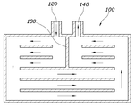
따라서, 도 1 내지 4와 같이 본 발명에 따른 차량용 냉각 장치는, 차량의 휠하우징에 마련되며, 냉각매체 유입구(120)와 유출구(140)가 형성되고, 유입구(120)를 통해 내부에 냉각매체가 도입되어 순환된 후 유출구(140)를 통해 토출되며, 일측면이 차량의 휠을 향해 노출됨으로써 휠하우징 내부를 흐르는 외기와 열교환을 하는 냉각채널(100) 및 냉각채널(100) 유입구(120) 및 유출구(140)와 차량의 발열부품(H) 사이를 연결함으로써 발열부품(H)이 냉각채널(100) 통해 냉각되도록 하는 냉각라인(200);을 포함한다.Therefore, as shown in Figures 1 to 4, the vehicle cooling apparatus according to the present invention is provided in the wheel housing of the vehicle, the
본 발명에 따른 냉각채널(100) 휠하우징에 마련되고, 냉각채널(100)내부에서 냉각매체가 유통된다. 냉각매체는 차량의 주행시에 휠(W)과 휠하우징 사이에 이격공간(S)을 와류하는 공기와의 열교환을 통해 냉각된다. 냉각되어 온도가 낮아진 냉각매체는 발열부품(H)으로 냉각라인(200)을 통해 공급되고, 발열부품(H)의 온도를 낮추게 되는 것이다.The
종래에는 라디에이터 그릴 등을 통해 유입된 공기와의 열교환을 통해 냉각매체를 냉각시키는 것들이 대부분이었다. 하지만, 차량이 주행하는 경우 라디에이터 그릴에 공기가 유입될 때 도 1과 같이 전방측 공기(A)에 의한 저항을 받게 된다. In the related art, most of the cooling medium is cooled through heat exchange with air introduced through a radiator grill or the like. However, when the vehicle is running, when air is introduced into the radiator grill, the resistance due to the front air A is received as shown in FIG. 1.
본 발명의 냉각장치는 휠하우징에 위치하기 때문에 라디에이터 그릴 등을 차량에 설치할 필요가 없으므로 차량의 전방부는 매끄럽운 구조를 가질 수 있게 설계가 가능하다. 따라서, 차량의 주행시에 전방측 공기(A)에 저항을 덜 받게 되므로 차량의 공력 성능이 우수해지는 장점이 있다. 그리고, 라디에이터 그릴이 설치되는 위치에 LED화면 등을 설치할 수 있으므로 다양한 설계를 할 수 있다는 장점이 있다.Since the cooling device of the present invention is located in the wheel housing, it is not necessary to install a radiator grill or the like in the vehicle, so the front part of the vehicle can be designed to have a smooth structure. Therefore, when the vehicle is running, it receives less resistance to the front air A, and thus has an advantage that the aerodynamic performance of the vehicle is excellent. In addition, since the LED screen and the like can be installed at a location where the radiator grill is installed, there is an advantage that various designs can be performed.
한편, 리저버탱크(R)는 냉각라인(200)에 배치된다. 냉각매체는 온도가 변화하는 경우 부피가 변할 수 있는데, 이와 같은 경우 리저버탱크(R)가 냉각매체를 수용하여 냉각매체의 부피 변화에 따른 냉각라인(200)의 손상 등을 방지하는 역할을 수행한다.Meanwhile, the reservoir tank R is disposed in the
도 2 내지 4는 냉각채널(100)의 내부구조를 나타낸 도면들이다.2 to 4 are views showing the internal structure of the
한편, 도 2 내지 4와 같이 냉각채널(100) 냉각매체 유입구(120)에 연결된 냉각유입유로 및 냉각매체 유출구(140)에 연결된 냉각유출유로로 내부가 구성되고, 냉각유입유로와 냉각유출유로는 냉각채널(100) 내부에서 서로 연결될 수 있다. 유입구(120)를 통해 유입된 가열된 냉각매체는 냉각유입유로 및 냉각유출유로를 지나면서 냉각되는 것이다. 그리고, 냉각된 냉각매체는 다시 발열부품(H) 등으로 공급되어 발열부품(H)과의 열교환을 통해 발열부품(H)의 온도를 낮추게 된다.On the other hand, as shown in Figures 2 to 4, the
구체적으로, 냉각매체 유입구(120) 및 유출구(140)는 인접하여 위치되고, 냉각유입유로 및 냉각유출유로는 유입구(120) 및 유출구(140)에 인접한 제1부분은 내부에 격벽(130)을 두고 분리되며 유입구(120) 및 유출구(140)와 떨어진 제2부분은 상호 연결될 수 있다. 또한, 냉각매체 유입구(120) 및 유출구(140)는 냉각채널(100) 중앙부에 위치되며, 냉각채널(100)의 중앙부 내측에서 유입구(120) 및 유출구(140)에 인접한 제1부분은 격벽(130)에 의해 냉각유입유로 및 냉각유출유로가 분리될 수 있다. 도 2에서 도시된 바와 같이, 유입구(120)를 통해 유입된 냉각매체는 도 2의 화살표 방향과 같이 유통되고, 유출구(140)를 통해 토출되어 발열부품(H) 등으로 공급되는 것이다. 따라서, 유입구(120) 및 유출구(140)에 인접한 제1부분은 격벽(130)을 통해 냉각매체간 상호 열교환을 하는 것을 방지하는 역할을 수행한다. 그리고, 유입구(120)를 통해 유입된 냉각매체는 냉각유입유로와 냉각유출유로가 상호 연결된 제2부분을 지나가며 유출구(140)로 유통되는 것이다.Specifically, the
또한, 도 4와 같이 냉각매체 유입구(120) 및 유출구(140)는 냉각채널(100) 일측 단부측에 위치되며, 냉각채널(100) 내부는 격벽(130)에 의해 냉각유입유로 및 냉각유출유로가 분리되고, 냉각채널(100) 타측 단부측 내부에서는 냉각유입유로 및 냉각유출유로가 연결될 수 있다. 유입구(120)를 통해 유입된 냉각매체는 도 4의 화살표 방향과 같이 유통되고, 유출구(140)를 통해 토출되어 발열부품(H) 등으로 공급되는 것이다. 따라서, 냉각유입유로 및 냉각유출유로를 격벽(130)을 통해 분리하여 유통되는 냉각매체간 상호 열교환되는 것을 방지한다.In addition, as shown in Figure 4, the
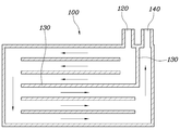
또한, 도 3과 같이 냉각매체 유입구(120)와 유출구(140)는 차량의 길이 방향을 따라서 휠하우징의 전방과 후방에 각각 위치되고, 냉각유입유로 및 냉각유출유로는 냉각채널(100) 내부에서 연결될 수 있다. 이와 같이 유입구(120)와 유출구(140)가 위치되는 경우에는 도 3의 화살표 방향을 따라서 냉각매체가 유통된다.In addition, as shown in Figure 3, the cooling
결국, 다양하게 냉각채널(100)의 유입구(120) 및 유출구(140)의 위치와 냉각채널(100)의 내부구조를 다양하게 할 수 있으므로, 차량의 내부구조 설계를 다양하게 할 수 있다는 장점이 있다. As a result, since the positions of the
한편, 도 1과 같이 냉각라인(200)에 마련되며, 차량의 주행중인 경우 가동하여 냉각매체가 유통되도록 하고, 차량이 정차중인 경우 정지하여 냉각매체가 유통되지 않도록 동작하는 펌프(P);를 더 포함할 수 있다. 차량이 주행중인 경우에는 이격공간(S)에 와류가 형성되므로 펌프(P)를 동작시켜 냉각매체를 유통하여 열교환이 활발히 이루어진다. 그러나, 차량이 정차중인 경우에는 냉각매체가 유통되지 않도록 펌프(P)가 동작하지 않으므로, 에너지를 절약가능한 장점이 있다.On the other hand, provided in the
한편, 도 7과 같이 냉각채널(100)중 차량의 휠을 향해 노출된 일측면은 금속재질로 이루어진 방열판(300)으로 구성될 수 있다. 방열판(300)은 이격공간(S)에서 와류되는 공기와 열교환을 한다. 따라서, 열 전도율이 높은 금속재질로 방열판(300)을 구성함으로써 냉각매체와 와류되는 공기 상호간의 열교환율을 극대화할 수 있다.On the other hand, as shown in Figure 7, one side exposed toward the wheel of the vehicle in the
또한, 도 7과 같이 방열판(300)의 상면부에는 냉각채널의 내부를 향해 돌출된 복수의 플랜지(F1)가 이격되어 형성될 수 있다. 플랜지(F1)가 형성되어 냉각매체가 방열판(300)과 열교환하는 면적이 증대되므로, 열교환율 또한 증대되는 장점이 있다.In addition, a plurality of flanges F1 protruding toward the inside of the cooling channel may be formed on the upper surface of the
또한, 도 8과 같이 방열판(300)의 하면부에는 차량의 휠을 향해 돌출된 복수의 방열핀(F2)이 이격되어 형성될 수 있다. 방열핀(F2)이 형성되어 방열판과 와류되는 공기 상호간에 열교환할 수 있는 면적이 넓어지므로 열교환율이 높아지는 장점이 있다.In addition, as shown in FIG. 8, a plurality of heat dissipation fins F2 protruding toward the wheels of the vehicle may be spaced apart from the lower surface of the
그리고, 도 7과 같이 방열판(300)의 외곽부는 냉각채널(100)의 테두리에 삽입되어 걸림고정될 수 있다. 이와 같이 방열판(300)을 냉각채널(100)에 삽입하여 고정시킴으로써, 방열판(300)이 냉각채널(100)으로부터 이탈되는 것을 방지할 수 있다.And, as shown in Figure 7, the outer portion of the
한편, 도 8은 냉각채널(100)을 사출형으로 형성하여 결합시킨 것이고, 도 9는 냉각채널(100)을 블로우 성형을 통해 일체형 구조를 가지도록 형성한 것이다. 이 외에도 통상의 지식을 가진 자에게 자명한 수준에서 다양하게 냉각채널(100)을 형성할 수 있을 것이다.On the other hand, Figure 8 is formed by combining the
또한, 도 5와 같이 냉각채널(100)은 차량의 복수의 휠하우징 내부에 각각 마련되고 복수의 냉각채널(100)은 하나의 냉각라인(200)에 의해 상호 연결될 수 있다. 구체적으로, 휠하우징과 냉각채널(100) 각각 4개가 마련되고 발열부품(H)은 제1부품(H1)과 제2부품(H2)으로 구성되며, 제1부품(H1)에서 토출된 냉각매체는 4개의 냉각채널(100)중 2개의 냉각채널(100) 지나며 냉각된 후 제2부품(H2)으로 유입되고, 제2부품(H2)에서 토출된 냉각매체는 나머지 2개의 냉각채널을 지나며 냉각될 수 있다. In addition, as shown in FIG. 5, the cooling
이와 같이, 4개의 냉각채널(100)을 마련함으로써, 냉각매체가 열교환할 수 있는 곳을 다수 형성하여 열교환율을 증대시킬 수 있다. 또한, 도 5에 도시된 바와 같이 제1부품(H1)을 지난 냉각매체는 차량의 후방에 있는 2개의 냉각채널(100)을 지나 제2부품(H2)으로 유입되므로, 제1부품(H1) 및 제2부품(H2)은 각각 2개의 냉각채널(100)을 통해 열교환 하므로 4륜 자동차에서 높은 열교환율을 가질 수 있는 구조가 설계 가능하다.In this way, by providing the four
또한, 도 6에서와 같이 휠하우징과 냉각채널(100)은 각각 2개가 마련되고 발열부품(H)은 제1부품(H1)과 제2부품(H2)으로 구성되며, 제1부품(H1)에서 토출된 냉각매체는 제2부품(H2)으로 유입되며, 제2부품(H2)에서 토출된 냉각매체는 2개의 냉각채널(100) 지나며 냉각되고, 제2부품(H2)은 제1부품(H1)보다 발열온도가 더 높은 것이 배치될 수 있다. In addition, as shown in FIG. 6, two wheel housings and two cooling
이와 같은 경우 제1부품(H1)을 지나 가열된 냉각매체라 하더라도 제2부품(H2)은 냉각시킬 수 있다. 따라서, 발열부품(H) 상호간에 온도가 상이한 경우, 열교환 효율을 극대화할 수 시스템을 설계 가능한 것이다.In this case, the second component H2 can be cooled even if the cooling medium is heated after passing through the first component H1. Therefore, when the temperature is different between the heating parts H, it is possible to design a system capable of maximizing heat exchange efficiency.
본 발명의 특정한 실시예에 관련하여 도시하고 설명하였지만, 이하의 특허청구범위에 의해 제공되는 본 발명의 기술적 사상을 벗어나지 않는 한도 내에서, 본 발명이 다양하게 개량 및 변화될 수 있다는 것은 당 업계에서 통상의 지식을 가진 자에게 있어서 자명할 것이다.Although illustrated and described in connection with specific embodiments of the present invention, it is understood in the art that the present invention may be variously improved and changed within the limits that do not depart from the technical spirit of the present invention provided by the following claims. It will be obvious to those of ordinary skill.
100 : 냉각채널
120 : 유입구
130 : 격벽
140 : 유출구
200 : 냉각라인
300 : 방열판
F1 : 플랜지
F2 : 방열핀
P : 펌프
H : 발열부품
H1 : 제1부품
H2 : 제2부품
R : 리저버탱크100: cooling channel 120: inlet
130: bulkhead 140: outlet
200: cooling line 300: heat sink
F1: Flange F2: Heat dissipation fin
P: Pump H: Heating parts
H1: First part H2: Second part
R: reservoir tank
Claims (14)
냉각채널의 유입구 및 유출구와 차량의 발열부품 사이를 연결함으로써 발열부품이 냉각채널을 통해 냉각되도록 하는 냉각라인;을 포함하는 차량용 냉각 장치.It is provided in the wheel housing of the vehicle, a cooling medium inlet and an outlet are formed, a cooling medium is introduced into the interior through the inlet, circulated, and then discharged through the outlet, and one side is exposed toward the wheel of the vehicle to expose the inside of the wheel housing. A cooling channel that exchanges heat with flowing outside air; And
Cooling device for a vehicle comprising a; cooling line for connecting the inlet and outlet of the cooling channel and the heating component of the vehicle to cool the heating component through the cooling channel.
냉각채널은 냉각매체 유입구에 연결된 냉각유입유로 및 냉각매체 유출구에 연결된 냉각유출유로로 내부가 구성되고, 냉각유입유로와 냉각유출유로는 냉각채널의 내부에서 서로 연결된 것을 특징으로 하는 차량용 냉각 장치.The method according to claim 1,
The cooling channel is composed of a cooling inflow passage connected to the cooling medium inlet and a cooling outflow passage connected to the cooling medium outlet, and the cooling inflow passage and cooling outflow passage are connected to each other inside the cooling channel.
냉각매체 유입구 및 유출구는 인접하여 위치되고, 냉각유입유로 및 냉각유출유로는 유입구 및 유출구에 인접한 제1부분은 내부에 격벽을 두고 분리되며 유입구 및 유출구와 떨어진 제2부분은 상호 연결된 것을 특징으로 하는 차량용 냉각 장치.The method according to claim 2,
The cooling medium inlet and outlet are located adjacently, and the first part adjacent to the inlet and outlet is separated by a partition wall therein, and the second part separated from the inlet and outlet is interconnected. Vehicle cooling system.
냉각매체 유입구 및 유출구는 냉각채널의 중앙부에 위치되며, 냉각채널의 중앙부 내측에서 유입구 및 유출구에 인접한 제1부분은 격벽에 의해 냉각유입유로 및 냉각유출유로가 분리된 것을 특징으로 하는 차량용 냉각 장치.The method according to claim 3,
The cooling medium inlet and outlet are located in the central portion of the cooling channel, and the first portion adjacent to the inlet and outlet inside the central portion of the cooling channel is a cooling device for a vehicle, characterized in that the cooling inlet and cooling outlet channels are separated by partition walls.
냉각매체 유입구 및 유출구는 냉각채널의 일측 단부측에 위치되며, 냉각채널의 내부는 격벽에 의해 냉각유입유로 및 냉각유출유로가 분리되고, 냉각채널의 타측 단부측 내부에서는 냉각유입유로 및 냉각유출유로가 연결된 것을 특징으로 하는 차량용 냉각 장치.The method according to claim 3,
The cooling medium inlet and outlet are located at one end side of the cooling channel, and the inside of the cooling channel is separated by a partition wall, and the cooling inflow passage and cooling outflow passage are separated, and inside the other end side of the cooling channel, the cooling inflow passage and cooling outflow passage Vehicle cooling device, characterized in that connected.
냉각매체 유입구와 유출구는 차량의 길이 방향을 따라서 휠하우징의 전방과 후방에 각각 위치되고, 냉각유입유로 및 냉각유출유로는 냉각채널의 내부에서 연결된 것을 특징으로 하는 차량용 냉각 장치.The method according to claim 2,
The cooling medium inlet and outlet are respectively located at the front and rear of the wheel housing along the longitudinal direction of the vehicle, and the cooling inflow passage and the cooling outflow passage are connected to the inside of the cooling channel.
냉각라인에 마련되며, 차량의 주행중인 경우 가동하여 냉각매체가 유통되도록 하고, 차량이 정차중인 경우 정지하여 냉각매체가 유통되지 않도록 동작하는 펌프;를 더 포함하는 것을 특징으로 하는 차량용 냉각 장치. The method according to claim 1,
It is provided on the cooling line, the vehicle cooling device for a vehicle, characterized in that it further comprises a pump that operates when the vehicle is running so that the cooling medium is distributed and stops when the vehicle is stopped so that the cooling medium is not distributed.
냉각채널 중 차량의 휠을 향해 노출된 일측면은 금속재질로 이루어진 방열판으로 구성된 것을 특징으로 하는 차량용 냉각 장치.The method according to claim 1,
A cooling device for a vehicle, characterized in that one side of the cooling channel exposed toward the wheel of the vehicle is composed of a heat sink made of a metallic material.
방열판의 상면부에는 냉각채널의 내부를 향해 돌출된 복수의 플랜지가 이격되어 형성된 것을 특징으로 하는 차량용 냉각 장치.The method according to claim 8,
A cooling device for a vehicle, characterized in that a plurality of flanges protruding toward the inside of the cooling channel are spaced apart from the upper surface of the heat sink.
방열판의 하면부에는 차량의 휠을 향해 돌출된 복수의 방열핀이 이격되어 형성된 것을 특징으로 하는 차량용 냉각 장치.The method according to claim 8,
A cooling device for a vehicle, characterized in that a plurality of radiating fins protruding toward the wheel of the vehicle are formed on the lower surface of the heat sink.
방열판의 외곽부는 냉각채널의 테두리에 삽입되어 걸림고정되는 것을 특징으로 하는 차량용 냉각 장치.The method according to claim 8,
Vehicle cooling device, characterized in that the outer portion of the heat sink is inserted into the rim of the cooling channel to be locked.
냉각채널은 차량의 복수의 휠하우징 내부에 각각 마련되고 복수의 냉각채널은 하나의 냉각라인에 의해 상호 연결된 것을 특징으로 하는 차량용 냉각 장치.The method according to claim 1,
The cooling channel is provided in each of the plurality of wheel housings of the vehicle, and the plurality of cooling channels are connected to each other by a cooling line.
휠하우징과 냉각채널은 각각 4개가 마련되고 발열부품은 제1부품과 제2부품으로 구성되며, 제1부품에서 토출된 냉각매체는 4개의 냉각채널 중 2개의 냉각채널을 지나며 냉각된 후 제2부품으로 유입되고, 제2부품에서 토출된 냉각매체는 나머지 2개의 냉각채널을 지나며 냉각되는 것을 특징으로 하는 차량용 냉각 장치.The method according to claim 12,
Four are provided for each of the wheel housing and the cooling channel, and the heating component is composed of the first component and the second component, and the cooling medium discharged from the first component passes through two of the four cooling channels and is cooled, followed by the second. A cooling device for a vehicle, characterized in that the cooling medium introduced into the part and discharged from the second part passes through the other two cooling channels and is cooled.
휠하우징과 냉각채널은 각각 2개가 마련되고 발열부품은 제1부품과 제2부품으로 구성되며, 제1부품에서 토출된 냉각매체는 제2부품으로 유입되며, 제2부품에서 토출된 냉각매체는 2개의 냉각채널을 지나며 냉각되고, 제2부품은 제1부품보다 발열온도가 더 높은 것을 특징으로 하는 차량용 냉각 장치.The method according to claim 12,
Two wheel housings and two cooling channels are provided, and the heat generating parts are composed of the first part and the second part, and the cooling medium discharged from the first part flows into the second part, and the cooling medium discharged from the second part is A cooling device for a vehicle, characterized in that it passes through two cooling channels and is cooled, and the second component has a higher heating temperature than the first component.
Priority Applications (4)
| Application Number | Priority Date | Filing Date | Title |
|---|---|---|---|
| KR1020180141390A KR20200057857A (en) | 2018-11-16 | 2018-11-16 | Cooling device for vehicle |
| US16/286,101 US10974587B2 (en) | 2018-11-16 | 2019-02-26 | Cooling system for vehicles |
| CN201910218683.0A CN111196181B (en) | 2018-11-16 | 2019-03-21 | Cooling system for vehicle |
| KR1020240089056A KR20240114730A (en) | 2018-11-16 | 2024-07-05 | Cooling device for vehicle |
Applications Claiming Priority (1)
| Application Number | Priority Date | Filing Date | Title |
|---|---|---|---|
| KR1020180141390A KR20200057857A (en) | 2018-11-16 | 2018-11-16 | Cooling device for vehicle |
Related Child Applications (1)
| Application Number | Title | Priority Date | Filing Date |
|---|---|---|---|
| KR1020240089056A Division KR20240114730A (en) | 2018-11-16 | 2024-07-05 | Cooling device for vehicle |
Publications (1)
| Publication Number | Publication Date |
|---|---|
| KR20200057857A true KR20200057857A (en) | 2020-05-27 |
Family
ID=70727166
Family Applications (2)
| Application Number | Title | Priority Date | Filing Date |
|---|---|---|---|
| KR1020180141390A KR20200057857A (en) | 2018-11-16 | 2018-11-16 | Cooling device for vehicle |
| KR1020240089056A KR20240114730A (en) | 2018-11-16 | 2024-07-05 | Cooling device for vehicle |
Family Applications After (1)
| Application Number | Title | Priority Date | Filing Date |
|---|---|---|---|
| KR1020240089056A KR20240114730A (en) | 2018-11-16 | 2024-07-05 | Cooling device for vehicle |
Country Status (3)
| Country | Link |
|---|---|
| US (1) | US10974587B2 (en) |
| KR (2) | KR20200057857A (en) |
| CN (1) | CN111196181B (en) |
Families Citing this family (1)
| Publication number | Priority date | Publication date | Assignee | Title |
|---|---|---|---|---|
| US11981195B2 (en) * | 2021-03-22 | 2024-05-14 | Honda Motor Co., Ltd. | Duct surface heat exchanger for vehicles |
Citations (1)
| Publication number | Priority date | Publication date | Assignee | Title |
|---|---|---|---|---|
| KR101542993B1 (en) | 2014-05-08 | 2015-08-12 | 현대자동차 주식회사 | Cooling and thermoelectric power generating system for vehicle |
Family Cites Families (7)
| Publication number | Priority date | Publication date | Assignee | Title |
|---|---|---|---|---|
| US3770049A (en) * | 1971-10-22 | 1973-11-06 | C Wright | Vehicle cooling system |
| JP5716825B2 (en) * | 2011-05-12 | 2015-05-13 | トヨタ自動車株式会社 | Cooler and method for manufacturing cooler |
| JP6164397B2 (en) * | 2013-02-01 | 2017-07-19 | スズキ株式会社 | Battery cooling system |
| DE102014001022A1 (en) * | 2014-01-27 | 2015-07-30 | Liebherr-Transportation Systems Gmbh & Co. Kg | Vehicle cooling circuit |
| US10286774B2 (en) * | 2014-04-18 | 2019-05-14 | Ford Global Technologies, Llc | Multiple zoned radiator |
| CN106828157A (en) * | 2017-01-25 | 2017-06-13 | 沈杞萌 | A kind of cooling system of new-energy automobile |
| CN107749506A (en) * | 2017-10-13 | 2018-03-02 | 高海燕 | A kind of battery pouring-basket cooling system |
-
2018
- 2018-11-16 KR KR1020180141390A patent/KR20200057857A/en not_active IP Right Cessation
-
2019
- 2019-02-26 US US16/286,101 patent/US10974587B2/en active Active
- 2019-03-21 CN CN201910218683.0A patent/CN111196181B/en active Active
-
2024
- 2024-07-05 KR KR1020240089056A patent/KR20240114730A/en active Application Filing
Patent Citations (1)
| Publication number | Priority date | Publication date | Assignee | Title |
|---|---|---|---|---|
| KR101542993B1 (en) | 2014-05-08 | 2015-08-12 | 현대자동차 주식회사 | Cooling and thermoelectric power generating system for vehicle |
Also Published As
| Publication number | Publication date |
|---|---|
| CN111196181A (en) | 2020-05-26 |
| US10974587B2 (en) | 2021-04-13 |
| KR20240114730A (en) | 2024-07-24 |
| CN111196181B (en) | 2024-08-16 |
| US20200156460A1 (en) | 2020-05-21 |
Similar Documents
| Publication | Publication Date | Title |
|---|---|---|
| CN107666202B (en) | Cooling device for new energy automobile motor | |
| US20180287452A1 (en) | Motor | |
| JP7152796B2 (en) | water cooling radiator | |
| JP2007241991A (en) | Low profile liquid cooled server heat sink | |
| KR102010301B1 (en) | Electric motor for electri vehicle | |
| KR20240114730A (en) | Cooling device for vehicle | |
| CN110268217A (en) | Liquid-cooling system for heat-producing device | |
| CN112393626A (en) | Liquid cooling radiating water discharge of water inlet multi-runner multi-water collecting box water adding pump | |
| KR101646129B1 (en) | Radiator for vehicle | |
| JP2017106702A (en) | Radiator for vehicle | |
| CN210381736U (en) | Heat dissipation apparatus and electrical device | |
| CN214848770U (en) | Liquid cooling plate and heat dissipation device | |
| CN212936500U (en) | Radiator with double-layer cooling structure | |
| CN209895255U (en) | Wind-liquid mixed heat dissipation case | |
| CN113412407A (en) | Heat exchanger | |
| JP2013145830A (en) | Radiator in liquid cooled system for electronic apparatus | |
| CN210454525U (en) | Three-dimensional radiator and vehicle-mounted power supply | |
| KR102141874B1 (en) | Induction heater for vehicle | |
| KR20080107024A (en) | Heat exchanger | |
| CN107846743A (en) | Microwave heating equipment | |
| CN107630744A (en) | Automobile radiators and automobile | |
| JP2018146216A (en) | Multi-passage heat exchanger | |
| KR101897931B1 (en) | System for cooling a processor in electronic device | |
| CN112467170B (en) | Heat radiator | |
| CN216852941U (en) | Multi-heat-source heat dissipation device |
Legal Events
| Date | Code | Title | Description |
|---|---|---|---|
| A201 | Request for examination | ||
| E902 | Notification of reason for refusal | ||
| AMND | Amendment | ||
| E601 | Decision to refuse application | ||
| AMND | Amendment | ||
| X601 | Decision of rejection after re-examination |