KR20200057621A - Robot and method for connecting cables to a robot - Google Patents
Robot and method for connecting cables to a robot Download PDFInfo
- Publication number
- KR20200057621A KR20200057621A KR1020190133926A KR20190133926A KR20200057621A KR 20200057621 A KR20200057621 A KR 20200057621A KR 1020190133926 A KR1020190133926 A KR 1020190133926A KR 20190133926 A KR20190133926 A KR 20190133926A KR 20200057621 A KR20200057621 A KR 20200057621A
- Authority
- KR
- South Korea
- Prior art keywords
- cable
- robot
- connector
- duct
- tube
- Prior art date
Links
Images

Classifications
-
- B—PERFORMING OPERATIONS; TRANSPORTING
- B25—HAND TOOLS; PORTABLE POWER-DRIVEN TOOLS; MANIPULATORS
- B25J—MANIPULATORS; CHAMBERS PROVIDED WITH MANIPULATION DEVICES
- B25J19/00—Accessories fitted to manipulators, e.g. for monitoring, for viewing; Safety devices combined with or specially adapted for use in connection with manipulators
- B25J19/0025—Means for supplying energy to the end effector
-
- B—PERFORMING OPERATIONS; TRANSPORTING
- B25—HAND TOOLS; PORTABLE POWER-DRIVEN TOOLS; MANIPULATORS
- B25J—MANIPULATORS; CHAMBERS PROVIDED WITH MANIPULATION DEVICES
- B25J19/00—Accessories fitted to manipulators, e.g. for monitoring, for viewing; Safety devices combined with or specially adapted for use in connection with manipulators
- B25J19/0025—Means for supplying energy to the end effector
- B25J19/0029—Means for supplying energy to the end effector arranged within the different robot elements
-
- B—PERFORMING OPERATIONS; TRANSPORTING
- B25—HAND TOOLS; PORTABLE POWER-DRIVEN TOOLS; MANIPULATORS
- B25J—MANIPULATORS; CHAMBERS PROVIDED WITH MANIPULATION DEVICES
- B25J19/00—Accessories fitted to manipulators, e.g. for monitoring, for viewing; Safety devices combined with or specially adapted for use in connection with manipulators
- B25J19/0075—Means for protecting the manipulator from its environment or vice versa
-
- B—PERFORMING OPERATIONS; TRANSPORTING
- B25—HAND TOOLS; PORTABLE POWER-DRIVEN TOOLS; MANIPULATORS
- B25J—MANIPULATORS; CHAMBERS PROVIDED WITH MANIPULATION DEVICES
- B25J9/00—Programme-controlled manipulators
- B25J9/0009—Constructional details, e.g. manipulator supports, bases
Landscapes
- Engineering & Computer Science (AREA)
- Mechanical Engineering (AREA)
- Robotics (AREA)
- Manipulator (AREA)
Abstract
Description
개시된 실시형태는 로봇 및 로봇에 케이블을 접속하는 방법에 관한 것이다.The disclosed embodiment relates to a robot and a method of connecting a cable to the robot.
종래, 다관절 아암의 기단측을 지지하는 기부를 마루면 등의 장착면에 고정하는 로봇이 알려져 있다. 또한, 기부를 직방체형상의 형상으로 하고, 다관절 아암을 지지하는 면 이외의 5개의 면을 장착면으로 하는 것에 의해, 바닥식에도 벽걸이식에도 대응한 로봇이 알려져 있다(예를 들어, 특허문헌 1 참조).Conventionally, a robot is known in which a base supporting the proximal end of a multi-joint arm is fixed to a mounting surface such as a floor surface. In addition, a robot that supports both a floor type and a wall-mounting type is known by setting the base to a rectangular parallelepiped shape and using five surfaces other than the surface supporting the multi-joint arm (for example, a patent document). 1).
또한, 로봇에는 다수의 급전용의 케이블이 접속되는 경우가 있어, 케이블과 다관절 아암의 간섭을 방지하는 관점에서, 베이스부의 내부에 케이블을 도입하는 기술도 제안되어 있다.In addition, there are cases where a plurality of cables for power feeding are connected to the robot, and a technique of introducing a cable into the base portion from the viewpoint of preventing interference between the cable and the articulated arm has also been proposed.
그렇지만, 베이스부에 다수의 케이블을 도입하는 경우, 각 케이블의 접속 작업이 번잡하게 되기 쉬워, 접속 작업의 효율의 면에서는 개선의 여지가 있다.However, when a large number of cables are introduced into the base portion, the connection work of each cable tends to be complicated, and there is room for improvement in terms of the efficiency of the connection work.
실시형태의 일 태양은, 접속 작업의효율을 높일 수 있는 로봇을 제공하는 것을 목적으로 한다.One aspect of the embodiment is to provide a robot capable of increasing the efficiency of the connection operation.
실시형태의 일 태양에 따른 로봇은, 다관절 아암과, 기부를 구비한다. 기부는 상기 다관절 아암의 기단측을 지지한다. 기부는 본체부와, 커넥터 유닛을 구비한다. 본체부는 상기 다관절 아암을 지지하는 지지면에 개구를 포함한다. 커넥터 유닛은 상기 본체부의 내부에 마련되는 내부 케이블에 접속되는 케이블 커넥터를 포함하며, 상기 케이블 커넥터에 있어서의 외부 케이블용의 접속구가 상기 개구로 향하도록 상기 본체부의 내부에 마련된다.The robot according to one aspect of the embodiment includes a multi-joint arm and a base. The base supports the proximal side of the articulated arm. The base has a body portion and a connector unit. The body portion includes an opening in a support surface supporting the articulated arm. The connector unit includes a cable connector connected to an internal cable provided inside the main body portion, and is provided inside the main body portion so that a connection port for an external cable in the cable connector faces the opening.
실시형태의 일 태양에 의하면, 접속 작업의 효율을 높일 수 있는 로봇을 제공할 수 있다.According to one aspect of the embodiment, a robot capable of increasing the efficiency of the connection operation can be provided.
도 1은 실시형태에 따른 로봇의 개요를 도시하는 도면이다.
도 2는 기부의 측면도이다.
도 3은 본체부에 있어서의 케이블 및 튜브의 위치 관계를 도시하는 모식도이다.
도 4는 케이블 덕트의 저면도이다.
도 5는 케이블 덕트의 측면도이다.
도 6은 케이블의 접속 순서를 나타내는 흐름도이다.
도 7은 로봇의 사시도이다.1 is a diagram showing an outline of a robot according to an embodiment.
2 is a side view of the base.
It is a schematic diagram which shows the positional relationship of a cable and a tube in a main body part.
4 is a bottom view of the cable duct.
5 is a side view of the cable duct.
6 is a flow chart showing the connection procedure of the cables.
7 is a perspective view of the robot.
이하, 첨부 도면을 참조하여, 본원이 개시하는 로봇의 실시형태를 상세하게 설명한다. 또한, 이하에 도시하는 실시형태에 의해 본 발명이 한정되는 것은 아니다. 또한, 이하에서는 로봇이 6축의 이른바 수직 다관절 로봇인 경우에 대해 주로 설명하지만, 로봇의 축 수나 축 구성에 대해는 이에 한정되지 않는다.Hereinafter, embodiments of the robot disclosed herein will be described in detail with reference to the accompanying drawings. In addition, this invention is not limited by embodiment shown below. In addition, hereinafter, the case where the robot is a so-called vertical multi-joint robot of six axes is mainly described, but the number of axes and the configuration of the axes of the robot are not limited thereto.
또한, 이하에 나타내는 실시형태에서는, 「직교」, 「수직」, 「평행」 혹은 「연직」과 같은 표현을 이용하지만, 엄밀하게 이들 상태를 만족하는 것을 필요로 하지 않는다. 즉, 상기한 각 표현은 제조 정밀도, 설치 정밀도, 처리 정밀도, 검출 정밀도 등의 편차를 허용하는 것으로 한다.In the embodiments shown below, expressions such as "orthogonal", "vertical", "parallel" or "vertical" are used, but it is not necessary to strictly satisfy these conditions. That is, each of the above-described expressions is assumed to allow deviations such as manufacturing precision, installation precision, processing precision, and detection precision.
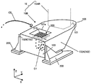
우선, 실시형태에 따른 로봇(10)의 개요에 대해 도 1을 이용하여 설명한다. 도 1은 실시형태에 따른 로봇(10)의 개요를 도시하는 도면이다. 또한, 도 1에서는 로봇(10)에 있어서의 기부(10B)의 구성에 대해 주로 도시하고 있으며, 다관절 아암(10AR)에 대해서는 장착 부분을 파선으로 나타내기만 하고, 구체적인 형상의 기재를 생략하고 있다. 또한, 로봇(10) 전체의 예에 대해는 도 7을 이용하여 후술하는 것으로 한다.First, the outline of the
또한, 도 1에는, 설명을 알기 쉽게 하기 위해, 연직 상방이 정방향인 Z축, 기부(10B)의 배면측이 부방향이며 정면측이 정방향인 Y축을 포함하는 3차원의 직교 좌표계를 도시하고 있다. 또한, X축은 기부(10B)의 배면측으로부터 보아 「좌측」을 부방향, 「우측」을 정방향이라 한다. 이하에서는, 「좌측」또는 「우측」이라 기재하는 경우가 있다. 또한, 이러한 직교 좌표계는 이하의 설명에서 이용하는 다른 도면에서도 나타내는 경우가 있다.In addition, FIG. 1 shows a three-dimensional orthogonal coordinate system including a Z-axis with a vertical upward direction, a Y-axis with a front side in the negative direction, and a front side in the forward direction for clarity. . In addition, the X-axis is referred to as the "left" in the negative direction and the "right" in the positive direction when viewed from the rear side of the
도 1에 도시하는 바와 같이, 실시형태에 따른 로봇(10)에 있어서의 기부(10B)는 본체부(100)와, 본체부(100)의 설치면으로의 장착에 이용되는 한쌍의 브래킷(200)을 포함한다. 또한, 설치면으로의 장착이 가능하도록 본체부(100)에 가공을 실시하는 것에 의해, 브래킷(200)을 생략하는 것으로 하여도 좋다.As shown in FIG. 1, the
본체부(100)는 다관절 아암(10AR)의 기단측을 지지하는 동시에, 예를 들어, 마루면이나 천정면 등의 설치면에 브래킷(200)을 거쳐서 고정된다. 한쌍의 브래킷(200)은 본체부(100)의 측면(102)(본체 측면(102))을 각각 지지하는 동시에, 본체부(100)를 설치면에 대해 고정한다.The
본체부(100)의 내부에는, 로봇(10)에 마련되는 액추에이터나 센서 등의 전자 기기에 급전하는 내부 케이블(C1)이 수용된다. 또한, 내부 케이블(C1)은 커넥터 유닛(300)을 거쳐서 외부 케이블(C2)에 접속된다.Inside the
또한, 본 실시형태에서는 내부 케이블(C1) 및 외부 케이블(C2)이 급전 케이블인 경우에 대해 설명하지만, 전자 신호를 전달하는 통신 케이블이어도 좋고, 급전 케이블과 통신 케이블이 혼재하고 있어도 좋다. 이하에서는, 내부 케이블(C1)과 외부 케이블(C2)을 통틀어 「케이블(C)」이라 하는 경우가 있다. 케이블(C)은 단일 케이블이라도 좋고, 복수의 케이블을 통틀어 피복한 집합 케이블이어도 좋다.In addition, although the case where the inner cable C1 and the outer cable C2 are feed cables is described in this embodiment, a communication cable that transmits an electronic signal may be used, or a feed cable and a communication cable may be mixed. Hereinafter, the internal cable C1 and the external cable C2 are collectively referred to as "cable C". The cable C may be a single cable or an aggregate cable covered with a plurality of cables.
도 1에 도시하는 바와 같이, 본체부(100)에 있어서 다관절 아암(10AR)을 지지하는 지지면(101)(도 1에서는 본체부(100)의 상면(101))에는, 개구(101a)가 마련된다. 또한, 본체부(100)의 내부에는 케이블 커넥터(310)를 복수 포함한 커넥터 유닛(300)이 마련된다. 여기에서, 커넥터 유닛(300)은 케이블 커넥터(310)에 있어서의 외부 케이블(C2)용의 접속구가 개구(101a)를 향하는 자세로 본체부(100)의 내부에 고정된다.As shown in FIG. 1, the opening 101a is provided in the support surface 101 (the
케이블 커넥터(310)의 뒷편(개구(101a) 방향과는 반대측)에는, 내부 케이블(C1)이 각각 접속되어 있으며, 외부 케이블(C2)을 개구(101a) 경유로 케이블 커넥터(310)에 접속하는 것에 의해, 외부 케이블(C2)과, 내부 케이블(C1)이 도통한다. 또한, 외부 케이블(C2)의 선단에는, 케이블 커넥터(310)에 대응하는 단자가 마련되어 있으며, 케이블 커넥터(310)로의 접속이 용이하다. 또한, 이러한 단자를 생략하는 것으로 하여도 좋다.The inner cable C1 is respectively connected to the back side of the cable connector 310 (opposite to the direction of the opening 101a), and the outer cable C2 is connected to the
또한, 도 1에는 복수의 케이블 커넥터(310)가 매트릭스형상으로 배열된 커넥터 유닛(300)을 도시하고 있지만, 케이블 커넥터(310)의 갯수는 1개 이상의 임의의 갯수로 할 수 있다. 또한, 케이블 커넥터(310)의 배열은 매트릭스형상으로 한정되지 않으며, 일렬로 배열하여도 좋고, 랜덤으로 배열하여도 좋다.In addition, although FIG. 1 shows a
이와 같이, 로봇(10)은 본체부(100)의 지지면(101)에 개구(101a)를 마련하고, 커넥터 유닛(300)의 접속구를 개구(101a)측으로 향하고 있으므로, 커넥터 유닛(300)에 대한 외부 케이블(C2)의 접속 작업을 효율적으로 실행할 수 있다.In this way, the
또한, 로봇(10)은 외부 케이블(C2)의 접속 작업을 실행하는 경우에, 본체부(100)의 내부에 있어서의 에어 튜브 등의 튜브가 방해가 되지 않는 구성을 구비하여도 좋지만, 이 점의 상세에 대해서는, 도 3을 이용하여 후술한다. 또한, 로봇(10)은 개구(101a)를 덮는 동시에, 외부 케이블(C2)의 선단측을 수용하는 케이블 덕트를 구비하여도 좋지만, 이 점의 상세에 대해서는, 도 4 등을 이용하여 후술한다.In addition, the
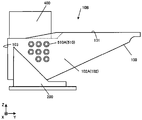
다음에, 도 1에 도시한 기부(10B)에 대해 도 2를 이용하여 더욱 상세하게 설명한다. 도 2는 기부(10B)의 측면도이다. 또한, 도 2는 기부(10B)를 X축 정방향측으로부터 본 측면도에 상당한다. 또한, 도 2에서는 도 1에 도시한 다관절 아암(10AR)의 기재를 생략하고 있다.Next, the
도 2에 도시하는 바와 같이, 한쌍의 본체 측면(102)에는, 에어 튜브 등의 튜브(T)(도 3 참조)를 접속하기 위한 튜브 커넥터(510)가, 배면(103) 부근의 위치에 각각 마련된다. 또한, 이하에서는, 본체부(100)의 내부에 수용되는 튜브(T)를 내부 튜브(T1), 본체부(100)의 외부로부터 본체부(100)에 접속되는 튜브(T)를 외부 튜브(T2)라 각각 기재하는 것으로 한다. 튜브(T)는 기체나 액체 등의 유체를 유통시킨다.As shown in Fig. 2, a pair of main
여기에서, 도 2에서는 본체 측면(102) 중, 우측의 본체 측면(102A)을 도시하고 있으며, 본체 측면(102A)에 마련되는 튜브 커넥터(510A)를 함께 도시하고 있다. 또한, 도 2에는 8개의 튜브 커넥터(510A)를 예시하고 있지만, 튜브 커넥터(510A)의 갯수에 대해서는, 필요에 따라서 1개 이상의 임의의 갯수로 할 수 있다. 또한, 본체 측면(102)의 좌측에 대해서는, 도 3을 이용하여 후술한다.Here, in FIG. 2, of the
또한, 도 2에 도시하는 바와 같이, 상면(101)에는 도 1에 도시한 개구(101a)를 덮는 동시에, 외부 케이블(C2)의 선단측을 수용하는 케이블 덕트(400)가 착탈 가능하게 마련된다. 또한, 케이블 덕트(400)도, 튜브 커넥터(510)와 마찬가지로, 배면(103) 부근의 위치에 마련된다.In addition, as shown in FIG. 2, the
즉, 케이블 덕트(400)는 튜브 커넥터(510)의 상방에 마련된다. 또한, 도 2에서는 배면(103)측이 1단 낮은 단차를 갖는 상면(101)을 도시했지만, 이러한 단차를 생략하여도 좋다. 또한, 케이블 덕트(400)의 상세에 대해서는, 도 4 등을 이용하여 후술한다.That is, the
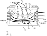
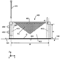
다음에, 본체부(100)에 있어서의 케이블(C) 및 튜브(T)의 위치 관계에 대해 도 3을 이용하여 설명한다. 도 3은 본체부(100)에 있어서의 케이블(C) 및 튜브(T)의 위치 관계를 도시하는 모식도이다. 여기에서, 도 3은 본체부(100)의 배면(103)측(Y축 부방향측)으로부터 본 본체부(100) 내부의 투시도에 상당한다. 또한. 각 부재의 절단면을 나타내는 해칭에 대해서는 생략하고 있다.Next, the positional relationship of the cable C and the tube T in the
도 3에 도시하는 바와 같이, 본체부(100)의 내부에는 내부 케이블(C1) 및 내부 튜브(T1)가 수용된다. 여기에서, 개구(101a)의 하방에는 본체부(100)의 내벽 등에 고정된 커넥터 유닛(300)이 마련되어 있으며, 커넥터 유닛(300)의 하방에는 내부 튜브(T1)가 배색(配索)되어 있다.As shown in FIG. 3, an inner cable C1 and an inner tube T1 are accommodated inside the
즉, 커넥터 유닛(300)과 개구(101a) 사이에는, 외부 케이블(C2)을 케이블 커넥터(310)에 접속하기 위한 작업 공간(WS)이 확보되어 있다. 이에 의해, 외부 케이블(C2)의 접속 작업시에는, 커넥터 유닛(300)에 의해, 내부 튜브(T1)로의 액세스가 저해되므로, 접속 작업에 수반하여 발생하기 쉬운 내부 튜브(T1)의 꺾임이나 데미지를 방지할 수 있다.That is, between the
도 3에 도시하는 바와 같이, 커넥터 유닛(300)은 케이블 커넥터(310)와, 본체부(100)의 내부 공간을 상하로 구획하는 플레이트(320)를 구비한다. 케이블 커넥터(310)는 외부 케이블(C2)용의 접속구가 상향(개구(101a) 방향)이 되는 자세로 플레이트(320)에 의해 지지된다. 또한, 케이블 커넥터(310)의 타단에는 내부 케이블(C1)이 접속되어 있다.As shown in FIG. 3, the
또한, 도 3에서는 평판형상의 플레이트(320)를 예시하고 있지만, 내부 튜브(T1)의 배색 공간과, 외부 케이블(C2) 접속을 위한 작업 공간(WS)을 구획할 수 있으면, 임의의 형상으로 할 수 있다. 예를 들어, 플레이트(320)의 단부를 상방이나 하방으로 절곡하거나, 플레이트(320)의 상방에만 작업 공간(WS)을 한정하는 울타리를 플레이트(320)의 상부에 마련하는 것으로 하여도 좋다.In addition, although FIG. 3 illustrates a plate-shaped
또한, 도 3에 도시한 바와 같이, 한쌍의 본체 측면(102)(제 1 본체 측면(102A) 및 제 2 본체 측면(102B))에는 튜브 커넥터(510)가 각각 대향하는 위치에 마련된다. 즉, 제 1 본체 측면(102A)에 마련되는 튜브 커넥터(510)와, 제 2 본체 측면(102B)에 마련되는 튜브 커넥터(510)는, 동일한 수이다. 또한, 제 1 본체 측면(102A)에 마련되는 튜브 커넥터(510)를 제 1 튜브 커넥터(510A)라 하고, 제 2 본체 측면(102B)에 마련되는 튜브 커넥터(510)를 제 2 튜브 커넥터(510B)라 한다.In addition, as shown in FIG. 3, a pair of body side surfaces 102 (first
내부 튜브(T1)는 분기 커넥터(520)를 거쳐서 2개로 분기되어 있으며, 분기된 내부 튜브(T1)는 대향하는 제 1 튜브 커넥터(510A) 및 제 2 튜브 커넥터(510B)에 각각 접속되어 있다. 또한, 도 3에 도시한 바와 같이, 분기 커넥터(520)는 커넥터 유닛(300)보다 하측에 배치된다.The inner tube T1 is branched into two via the
여기에서, 분기된 내부 튜브(T1)는 각각, 엘보 조인트(JE)를 거쳐서 튜브 커넥터(510)에 접속된다. 여기에서, 엘보 조인트(JE)는, 축선이 굴곡되며, 굴곡된 조인트의 선단쪽 부분이 굴곡된 조인트의 다른쪽 부분의 축선을 중심으로 회전 가능한 타입의 조인트이다. 엘보 조인트(JE)를 이용하는 것에 의해, 예를 들어, 내부 튜브(T1)의 방향을 하측으로 향하게 할 수 있어서, 내부 튜브(T1)를 작업 영역(WS)으로부터 확실히 이격시킬 수 있다. 또한, 엘보 조인트(JE)의 굴곡 각도는 직각으로 한정되지 않으며, 임의의 각도로 할 수 있다.Here, the branched inner tubes T1 are respectively connected to the
이와 같이, 내부 튜브(T1)는 2개로 분기되며, 제 1 본체 측면(102A)의 제 1 튜브 커넥터(510A)에도, 제 2 본체 측면(102B)의 제 2 튜브 커넥터(510B)에도 접속된다. 즉, 대향하는 본체 측면(102)의 어느 쪽에도, 분기 전의 내부 튜브(T1)에 접속된 튜브 커넥터(510)를 각각 배치할 수 있다.In this way, the inner tube T1 is divided into two, and is also connected to the
따라서, 대향하는 본체 측면(102)의 한쪽에만 외부 튜브(T2)를 집중시켜 접속하는 것이 가능해진다. 예를 들어, 본체부(100)의 좌측에 접속하기 어려운 환경의 경우에는, 제 1 본체 측면(102A)의 제 1 튜브 커넥터(510A)에, 우측에 접속하기 어려운 환경의 경우에는, 제 2 본체 측면(102B)의 제 2 튜브 커넥터(510B)에 외부 튜브(T2)를 집중시켜 접속하면 좋다. 도 3에는 제 1 본체 측면(102A)측에 전체 외부 튜브(T2)를 집중시켜 접속한 경우를 도시하고 있다.Therefore, it becomes possible to concentrate and connect the outer tube T2 to only one of the opposing main body side surfaces 102. For example, in the case of an environment in which it is difficult to connect to the left side of the
또한, 전체 외부 튜브(T2) 중 일부를 제 1 튜브 커넥터(510A)에 접속하고, 나머지를 제 2 튜브 커넥터(510B)에 접속하는 것으로 하여도 좋다. 또한, 제 1 튜브 커넥터(510A) 및 제 2 튜브 커넥터(510B) 중, 외부 튜브(T2)를 접속하지 않는 쪽에는, 덮개 부재 등을 장착하여 폐색하는 것으로 하면 좋다.Further, a part of the entire outer tube T2 may be connected to the
또한, 도 3에서는 가장 상측의 튜브 커넥터(510)가, 커넥터 유닛(300)보다 높은 위치에 있는 경우를 도시하고 있지만, 전체 튜브 커넥터(510)를 커넥터 유닛(300)에 있어서의 플레이트(320)보다 낮은 위치에 마련하는 것으로 하여도 좋다. 이와 같이 하는 것에 의해, 작업 영역(WS)으로부터 내부 튜브(T1)로의 액세스를 더욱 실행하기 어렵게 할 수 있다.In addition, although the
또한, 튜브 커넥터(510)의 배치를 도 3과 마찬가지로 하고, 제 1 튜브 커넥터(510A)측 및 제 2 튜브 커넥터(510B)측의 플레이트(320)의 단부를 상측으로 절곡하는 것으로 하여도 좋다. 이와 같이 하여도, 작업 영역(WS)으로부터 내부 튜브(T1)로의 액세스를 하기 어렵게 할 수 있다.In addition, the arrangement of the
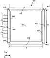
다음에, 도 2에 도시한 케이블 덕트(400)에 대해 도 4 및 도 5를 이용하여 더욱 상세하게 설명한다. 도 4는 케이블 덕트(400)의 저면도이며, 도 5는 케이블 덕트(400)의 측면도이다. 또한, 도 4 및 도 5에는 저면측이 개방된 바닥부를 갖는 통형상으로, 직방체형상의 케이블 덕트(400)를 도시하고 있다. 또한, 도 5에는 도 1에 도시한 본체부(100)의 상면(지지면)(101)의 일부를 도시하고 있다.Next, the
우선, 케이블 덕트(400)의 저면 형상에 대해, 도 4를 이용하여 설명한다. 도 4에 도시하는 바와 같이, 케이블 덕트(400)는 도 1에 도시한 개구(101a)의 둘레를 덮고, 개구(101a)와 연통하도록 도려내어진 저면(403)을 구비한다. 또한, 저면(403)에는 4개의 코너부를 각각 관통하는 관통 구멍(410)이 형성되어 있다. 여기에서, 저면(403)의 외형은 정방 형상이다. 또한, 인접하는 관통 구멍(410)의 축선간의 폭(거리)은 모두 「W」이며, 각각 동일하다.First, the shape of the bottom surface of the
또한, 케이블 덕트(400)는 4개의 덕트 측면(402)을 구비하고 있다. 여기에서, 4개의 덕트 측면(402) 중 어느 하나는, 개구를 갖고 있으며, 도 1에 도시한 외부 케이블(C2)에 장착되는 케이블 그라운드(450)를 포함한 기밀성 확보 기구인 도출부(460)가 마련된다. 즉, 덕트 측면(402) 중 어느 하나에 마련되는 개구는 도출부(460)에 의해 폐색된다.In addition, the
여기에서, 케이블 그라운드(450)는 예를 들어, 외부 케이블(C2)(도 3 참조)의 축선을 따르는 평면으로 2분할되어 있으며, 외부 케이블(C2)의 선단측의 여분의 길이를 임의의 길이로 할 수 있다. 또한, 케이블 그라운드(450)는 도출부(460)를 거쳐서 케이블 덕트(400)와의 기밀성을 확보한 상태에서, 덕트 측면(402) 중 어느 하나에 장착된다.Here, the
여기에서, 상기한 바와 같이, 인접하는 관통 구멍(410)의 축선간의 폭은 각각 동일하므로, 도출부(460)의 방향은 용이하게 변경 가능하다. 또한, 도 4에는 도출부(460)가 Y축 부방향측을 향하는 경우를 예시하고 있지만, Y축 정방향측, X축 정방향측 및 X축 부방향측의 어느 방향이어도, 추가의 가공 등을 필요로 하는 일 없이, 도출부(460)의 방향, 즉, 외부 케이블(C2)의 도출 방향을 용이하게 변경 가능하다.Here, as described above, since the widths between the axes of the adjacent through
다음에, 케이블 덕트(400)의 측면 형상에 대해 도 5를 이용하여 설명한다. 도 5에 도시하는 바와 같이, 케이블 덕트(400)에 있어서의 덕트 측면(402)의 형상은, 폭에 대해 높이가 작은 직사각형상이다. 또한, 케이블 덕트(400)와, 본체부(100)의 상면(101) 사이에는, 도 4에 도시한 저면(403)과 동일한 형상의 개스킷(G)이 마련된다. 또한, 개스킷(G)을 이용하는 것에 의해, 본체부(100)와 케이블 덕트(400)의 기밀성을 높일 수 있다.Next, the side shape of the
또한, 덕트 측면(402)의 단부에는 도 4에도 도시한 관통 구멍(410)이 형성되어 있다. 그리고, 케이블 덕트(400)는 관통 구멍(410)을 관통하는 보스(470)에 의해, 본체부(100)의 상면(101)에 고정된다. 여기에서, 보스(470)는 관통 구멍(410)의 내경보다 외경이 작은 축과, 축보다 외경이 큰 헤드부를 갖고 있으며, 축의 선단에는 체결용의 나사홈이 형성되어 있다.In addition, a through
또한, 관통 구멍(410)의 상단에는 보스(470)의 헤드부를 수용하는 카운터보어(411)가 형성되어 있다. 즉, 보스(470)의 헤드부는 케이블 덕트(400)의 상면(401)으로부터 돌출되지 않는다. 이에 의해, 케이블 덕트(400)에 장애물 등이 걸리는 사태를 방지할 수 있다. 또한, 카운터보어(411)에 대해서는 생략하는 것으로 하여도 좋다.In addition, a
관통 구멍(410)의 축선 간의 폭은 「W」이며, 관통 구멍(410)의 높이는 「H」이다. 여기에서, 축선 간의 폭과 관통 구멍(410)의 높이의 관계는, 식 「W≤H×2」로 나타난다. 즉, 축선 간의 폭(거리)은 관통 구멍(410)의 높이의 2배 이하이다.The width between the axes of the through
이와 같이, 축선간의 폭을 관통 구멍(410)의 높이의 2배 이하로 하는 것에 의해, 케이블 덕트(400)를 상면(101)에 장착할 때의 보스(470)의 헤드부에 의한 가압력을 구석구석까지 저면(403)에 전달할 수 있다. 이것은, 보스(470)의 헤드부에 의한 가압력은 케이블 덕트(400)에 대해 원추형상으로 넓어지도록 전달되며, 원추의 경사면의 경사는 대체로 45도이기 때문이다.Thus, by making the width between the axes less than twice the height of the through
즉, 1개의 보스(470)에 의한 가압력은 폭 방향에 대해서는 관통 구멍(410)의 높이인 「H」의 범위에 전달되므로, 축선 간의 폭을 「H」의 2배 이하로 하면, 폭 전체에 걸쳐서 가압력이 전달되기 때문이다. 또한, 가압력은 헤드부의 외주를 시발점으로 하여 전달되므로, 헤드부의 외경을 크게 하거나, 헤드부보다 외경이 큰 와셔를 이용하는 것에 의해, 가압력의 전달 범위를 넓힐 수 있다.That is, since the pressing force by one
여기에서, 카운터보어(411)의 높이는 일반적으로, 케이블 덕트(400)의 높이에 대해 작으므로, 측면(402)의 높이를 관통 구멍(410)의 높이인 「H」로 간주하는 것으로 하여도 좋다. 또한, 관통 구멍(410)은 측면(402)의 단부에 각각 마련되므로, 측면(402)의 폭을 관통 구멍(410)의 축선 간의 폭인 「W」로 간주하는 것으로 하여도 좋다. 즉, 측면(402)의 폭을 측면(402)의 높이의 2배 이하로 하는 것으로 하여도 좋다.Here, since the height of the
또한, 도 5에 도시한 바와 같이, 케이블 덕트(400)의 측면(402)에는, 상면(401)이 넓고 저면(403)을 향하여 좁아지는 형상(대략 삼각 형상)의 육박부(肉薄部)(TH)를 마련하는 것으로 하여도 좋다. 육박부(TH)는, 그 두께가 측면(402)의 다른 부분의 두께보다 더 작게 형성된다. 상기한 바와 같이, 보스(470)에 의한 가압력이 미치기 어려운 부위(상기한 원추에 포함되지 않는 영역)에 육박부(TH)를 마련함으로써, 가압력은 확실히 전달하면서, 케이블 덕트(400)의 경량화를 도모할 수 있다. 이러한 육박부(TH)는 도출부(460)가 마련되는 측면(402) 이외의 측면(402)에 마련할 수 있다.In addition, as shown in FIG. 5, on the
다음에, 케이블 덕트(400)를 이용한 케이블(C)의 접속 순서에 대해 도 6을 이용하여 설명한다. 도 6은 케이블(C)의 접속 순서를 나타내는 흐름도이다. 도 6에 나타내는 바와 같이, 도출부(460)를 통과시킨 외부 케이블(C2)의 선단측을 여분의 길이만큼 케이블 덕트(400)에 수용한다(단계(S101)).Next, the connection procedure of the cable C using the
여기에서, 케이블 덕트(400)는 직방체형상의 내부 공간을 갖고 있으므로, 예를 들어 외부 케이블(C2)을 복수 회 굽힌 상태로 격납하는 것에 의해, 충분한 여분의 길이를 확보할 수 있다. 또한, 케이블 덕트(400)의 저면(403)을 상방을 향한 상태에서 작업을 실행할 수 있으므로, 작업을 실행하기 쉽다.Here, the
다음에, 외부 케이블(C2)에 케이블 그라운드(450)를 장착한다(단계(S102)). 여기에서, 케이블 그라운드(450)는 외부 케이블(C2)을 따라서 자유롭게 슬라이드 가능하다. 또한, 단계(S102)의 순서를 단계(S101)의 순서보다 먼저 실행하여도 좋다.Next, the
이어서, 케이블 그라운드(450)를 케이블 덕트(400)의 도출부(460)에 고정한다(단계(S103)). 케이블 그라운드(450)를 도출부(460)에 장착하는 것에 의해, 외부 케이블(C2)과, 케이블 덕트(400)의 기밀성이 확보된다.Subsequently, the
그리고, 외부 케이블(C2)을 커넥터 유닛(300)에 접속한다(단계(S104)). 또한, 단계(S104)의 순서를 단계(S101) 순서의 직후나, 단계(S102) 순서의 직후에 실행하여도 좋다.Then, the external cable C2 is connected to the connector unit 300 (step S104). In addition, the order of step S104 may be executed immediately after the order of step S101 or immediately after the order of step S102.
다음에, 케이블 덕트(400)에 있어서의 도출부(460)의 방향을 상기한 4개의 방향 중에서 소망의 방향으로 한 후에, 케이블 덕트(400)를 기부(10B)에 고정한다(단계(S105)). 또한, 커넥터 유닛(300)에는 미리 내부 케이블(C1)이 접속되어 있으므로, 이들 순서에 의해 내부 케이블(C1)과, 외부 케이블(C2)의 도통 작업이 완료된다.Next, after the direction of the lead-out
또한, 단계(S105)의 순서에 의해 케이블 덕트(400)와, 본체부(100)에 있어서의 개구(101a)의 주위의 기밀성이 확보된다. 이에 의해, 본체부(100)의 내부와, 로봇(10)의 외부가 격리된다. 예를 들어, 폭발성 분위기에 로봇(10)을 설치하여도, 로봇(10)의 내부는, 폭발성 분위기로부터 격리된다.In addition, airtightness around the
도 6에 나타낸 바와 같이, 본 실시형태에 따른 기부(10B)를 갖는 로봇(10)에 의하면 케이블(C)의 접속 작업을 실행하기 쉽다. 따라서, 로봇(10)을 설치 현장에 설치할 때의 작업 노력을 저감하고, 또한, 작업 시간을 단축할 수 있다.As shown in Fig. 6, according to the
또한, 본 실시형태에 따른 기부(10B)를 갖는 로봇(10)에서는, 외부 케이블(C2)을 내부에 도입하기 위한 개구(101a)를 1개소로 하고, 외부 케이블(C2)의 접속방향에 대해서는, 케이블 덕트(400)의 장착방향을 변경하는 것에 의해 대응하는 것으로 했다. 따라서, 외부 케이블(C2)의 접속방향에 따라서 복수의 개소에 개구를 마련할 필요가 없어, 제조 비용을 억제할 수 있다.In addition, in the
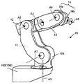
다음에, 기부(10B)를 구비하는 로봇(10)의 예에 대해 도 7을 이용하여 설명한다. 도 7은 로봇(10)의 사시도이다. 도 7에 도시하는 바와 같이, 로봇(10)은 선회축(A0) 내지 제 5 축(A5)의 6축을 갖는 이른바 수직 다관절 로봇이다. 이와 같이, 로봇(10)은 6축의 로봇이므로, 선단의 위치에 대해 3개의 자유도를 가지며, 선단의 방향에 대해 3개의 자유도를 갖는다. 즉, 선단을 3차원의 임의의 위치, 또한, 3차원의 임의의 방향으로 자유롭게 변경할 수 있다.Next, an example of the
도 7에 도시한 바와 같이, 로봇(10)은 기단측으로부터 선단측을 향하며, 도 1 등에 도시한 기부(10B)(브래킷(200)을 생략하고 있으므로 본체부(100)만을 도시)와, 선회부(10S)와, 제 1 아암(11)과, 제 2 아암(12)과, 제 3 아암(13)과, 손목부(14)를 구비한다. 여기에서, 선회부(10S) 내지 손목부(14)는 도 1에 도시한 다관절 아암(10AR)에 상당한다. 또한, 손목부(14)의 선단측에는 작업용의 임의의 툴을 착탈 가능하게 장착할 수 있다.As shown in FIG. 7, the
또한, 「아암」의 개념에는 제 1 아암(11), 제 2 아암(12) 및 제 3 아암(13)에 부가하여 손목부(14)나 선회부(10S)도 포함되는 것으로 한다. 즉, 로봇(10)에 있어서, 회전이나 선회 등의 가동 부위를 「아암」이라 할 수 있다.In addition, the concept of the "arm" is to be included in addition to the
기부(10B)는 도 1 등을 이용하여 상세하게 설명했으므로 여기에서의 설명을 생략한다. 선회부(10S)는 기부(10B)에 지지되며, 연직방향의 선회축(A0을 중심으로 선회한다. 제 1 아암(11)은 기단측이 선회부(10S)에 지지되며, 선회축(A0)과 수직인 제 1 축(A1)을 중심으로 선회한다. 제 2 아암(12)은 기단측이 제 1 아암(11)의 선단측에 지지되며, 제 1 축(A1)과 평행한 제 2 축(A2)을 중심으로 선회한다.Since the
제 3 아암(13)은 기단측이 제 2 아암(12)의 선단측에 지지되며, 제 2 축(A2)과 수직인 제 3 축(A3)을 중심으로 회전한다. 손목부(14)는 선회부(14a)와, 회전부(14b)를 포함한다. 선회부(14a)는 기단측이 제 3 아암(13)의 선단측에 지지되며, 제 3 축(A3)과 수직인 제 4 축(A4) 을 중심으로 선회한다.The
회전부(14b)는 기단측이 선회부(14a)의 선단측에 지지되며, 제 4 축(A4)과 직교하는 제 5 축(A5)을 중심으로 회전한다. 또한, 회전부(14b)의 선단측에는 상기한 툴 등을 장착할 수 있다. 또한, 선회부(14a) 및 회전부(14b)는 중공이며, 툴에 접속하는 케이블이나 튜브 등이 걸리는 중공 부분에 관통 삽입된다. 이에 의해, 손목부(14) 주위에 케이블 등을 배색할 필요가 없으므로, 로봇(10)의 작업성을 향상시킬 수 있다.The rotating
또한, 도 7에 도시한 로봇(10)은 일 예이며, 도 1 등에 도시한 기부(10B)는 전체 축 수나 축 구성의 다관절 아암(10AR)에 적용할 수 있다.In addition, the
상술한 바와 같이, 실시형태에 따른 로봇(10)은 다관절 아암(10AR)과, 기부(10B)를 구비한다. 기부(10B)는 다관절 아암(10AR)의 기단측을 지지한다. 기부(10B)는 본체부(100)와, 커넥터 유닛(300)을 구비한다. 본체부(100)는 다관절 아암(10AR)을 지지하는 지지면(101)에 개구(101a)를 포함한다.As described above, the
커넥터 유닛(300)은 본체부(100)의 내부에 마련되는 케이블(C1)에 접속되는 케이블 커넥터(310)를 포함하며, 케이블 커넥터(310)에 있어서의 외부 케이블(C2)용의 접속구가 개구(101a)로 향하도록 본체부(100)의 내부에 마련된다. 또한, 본체부(100)는 내부에 마련되는 내부 튜브(T1)와 외부 튜브(T2)를 연결하는 튜브 커넥터(510)를, 서로 대향하는 본체 측면들(102)의 각각에 구비한다.The
이와 같이, 로봇(10)은 기부(10B)의 지지면(101)에 개구(101a)를 마련하고, 커넥터 유닛(300)의 접속구를 개구(101a)측을 향하고 있으므로, 커넥터 유닛(300)에 대한 외부 케이블(C2)의 접속 작업을 효율적으로 실행할 수 있다. 따라서, 로봇(10)에 대한 접속 작업의 효율화를 높일 수 있다.In this way, the
또한, 본 실시형태에서는 본체부에 마련하는 개구를 직사각 형상으로 하고, 개구를 폐색하는 케이블 덕트의 저면 형상을 정방형 형상으로 하는 경우에 대해 설명했지만, 이러한 개구를 원형상으로 하고, 케이블 덕트의 저면 형상도 원형상으로 하는 것으로 하여도 좋다. 이와 같이 하여도, 케이블 덕트에 있어서의 외부 케이블의 도출 방향을 자유롭게 변경할 수 있다. 또한, 케이블 덕트의 측면 형상에 대해서는, 돔형상 등의 반구 형상으로 하여도 좋다.In addition, in the present embodiment, a case has been described in which the opening provided in the main body portion has a rectangular shape and the bottom face shape of the cable duct closing the opening has a square shape, but these openings have a circular shape and the bottom face of the cable duct. The shape may also be made circular. Even in this way, the direction in which the external cables are drawn out in the cable duct can be freely changed. Moreover, about the side shape of a cable duct, you may set it as a hemispherical shape, such as a dome shape.
다른 효과나 변형예는 당업자에 의해 용이하게 도출할 수 있다. 이 때문에, 본 발명의 것보다 광범위한 태양은, 이상과 같이 나타내며 또한 기술한 특정의 상세 및 대표적인 실시예로 한정되는 것은 아니다. 따라서, 첨부된 특허 청구의 범위 및 그 균등물에 의해 정의되는 총괄적인 발명의 개념의 정신 또는 범위로부터 일탈하는 일 없이, 여러가지 변경이 가능하다.Other effects and modifications can be easily derived by those skilled in the art. For this reason, a broader aspect than that of the present invention is not limited to the specific details and representative examples shown and described above. Accordingly, various modifications are possible without departing from the spirit or scope of the overall concept of the invention as defined by the appended claims and their equivalents.
10 : 로봇
10 : AR다관절 아암
10B : 기부
10S : 선회부
11 : 제 1 아암
12 : 제 2 아암
13 : 제 3 아암
14 : 손목부
14a : 선회부
14b : 회전부
100 : 본체부
101 : 상면(지지면)
101a : 개구
102 : 측면(본체 측면)
103 : 배면
200 : 브래킷
300 : 커넥터 유닛
310 : 케이블 커넥터
320 : 플레이트
400 : 케이블 덕트
401 : 상면
402 : 측면(덕트 측면)
403 : 저면
410 : 관통 구멍
411 : 카운터보어
450 : 케이블 그라운드
460 : 도출부
470 : 보스
510 : 튜브 커넥터
520 : 분기 커넥터
A0 : 선회축
A1 : 제 1 축
A2 : 제 2 축
A3 : 제 3 축
A4 : 제 4 축
A5 : 제 5 축
C1 : 내부 케이블
C2 : 외부 케이블
G : 개스킷
JE : 엘보 조인트
T1 : 내부 튜브
T2 : 외부 튜브
TH : 육박부 10: robot 10: AR multi-joint arm
10B:
11: 1st arm 12: 2nd arm
13: third arm 14: wrist
14a: turning
100: main body 101: upper surface (support surface)
101a: opening 102: side (body side)
103: back 200: bracket
300: connector unit 310: cable connector
320: plate 400: cable duct
401: upper surface 402: side (duct side)
403: bottom 410: through hole
411: Counter bore 450: Cable ground
460: lead part 470: boss
510: tube connector 520: branch connector
A0: pivot axis A1: first axis
A2: 2nd axis A3: 3rd axis
A4: 4th axis A5: 5th axis
C1: inner cable C2: outer cable
G: Gasket JE: Elbow joint
T1: inner tube T2: outer tube
TH: yukbakbu
Claims (11)
상기 아암의 기단측을 지지하는 기부를 구비하고,
상기 기부는,
상기 아암을 지지하는 지지면에 개구를 포함하는 본체부와,
상기 본체부의 내부에 마련되는 내부 케이블에 접속되는 케이블 커넥터를 포함하며, 상기 케이블 커넥터에 있어서의 외부 케이블용의 접속구가 상기 개구로 향하도록 상기 본체부의 내부에 마련되는 커넥터 유닛을 구비하는
로봇.Arm,
It has a base for supporting the proximal end of the arm,
The donation,
A body part including an opening in a support surface supporting the arm,
It includes a cable connector connected to an inner cable provided inside the body portion, and provided with a connector unit provided inside the body portion so that the connection port for the external cable in the cable connector faces the opening.
robot.
상기 본체부는,
상기 본체부의 내부에 마련되는 내부 튜브와 외부 튜브를 연결하는 튜브 커넥터를, 서로 대향하는 본체 측면들의 각각에 구비하는
로봇.According to claim 1,
The body portion,
A tube connector for connecting the inner tube and the outer tube provided inside the body part is provided on each of the side surfaces of the body facing each other.
robot.
상기 내부 튜브를 분기하는 분기 커넥터를 구비하고,
상기 분기 커넥터에 의해 분기된 상기 내부 튜브는,
상기 서로 대향하는 본체 측면들의 상기 튜브 커넥터에 각각 접속되는
로봇.According to claim 2,
And a branch connector for branching the inner tube,
The inner tube branched by the branch connector,
Respectively connected to the tube connectors of the body side surfaces facing each other
robot.
상기 분기 커넥터는,
상기 커넥터 유닛보다 하측에 배치되는
로봇.The method of claim 3,
The branch connector,
Disposed below the connector unit
robot.
상기 지지면의 상기 개구를 덮는 동시에, 상기 케이블 커넥터의 상기 접속구에 접속되는 상기 외부 케이블의 선단측을 수용하며, 상기 본체부에 착탈 가능하게 결합되는 케이블 덕트를 구비하는
로봇.The method according to any one of claims 1 to 4,
A cable duct which covers the opening of the support surface and accommodates the front end side of the external cable connected to the connection port of the cable connector, and is detachably coupled to the main body part.
robot.
상기 케이블 덕트는
상기 개구로부터 보아 정방형상이며,
상기 본체부에 결합된 때 상기 개구를 향하는 면이 개방된 통형상인
로봇.The method of claim 5,
The cable duct
Seen from the opening, it is square,
When coupled to the body portion, the surface facing the opening is a cylindrical shape
robot.
상기 케이블 덕트는,
4개의 덕트 측면 중 어느 하나에 상기 외부 케이블이 통과하는 도출부를 구비하는
로봇.The method of claim 6,
The cable duct,
Equipped with a lead portion through which the external cable passes on any one of the four duct side
robot.
상기 케이블 덕트는,
상기 개구로부터 보아 4개의 코너부를 각각 관통하는 관통 구멍을 구비하고,
상기 덕트 측면은,
상기 관통 구멍에 있어서의 축선 간의 폭이 상기 관통 구멍의 높이의 2배 이하인
로봇.The method of claim 7,
The cable duct,
It has a through hole through each of the four corners as seen from the opening,
The side of the duct,
The width between the axes in the through hole is equal to or less than twice the height of the through hole.
robot.
외부 케이블이 케이블 덕트의 일 측면에 마련된 도출부를 통과하는 단계;
상기 외부 케이블에 케이블 그라운드를 장착하는 단계;
상기 케이블 그라운드를 상기 케이블 덕트의 상기 도출부에 고정하는 단계;
상기 본체부의 내부에 마련되는 커넥터 유닛에 상기 외부 케이블을 접속하는 단계; 및
상기 케이블 덕트에 있어서의 도출부의 방향을 소망의 방향으로 한 상태에서 상기 케이블 덕트를 상기 기부에 고정하는 단계를 포함하는
로봇에 케이블을 접속하는 방법.A method for connecting a cable to a robot having an arm and a base supporting the base end side of the arm,
An external cable passing through a lead portion provided on one side of the cable duct;
Attaching a cable ground to the external cable;
Fixing the cable ground to the lead portion of the cable duct;
Connecting the external cable to a connector unit provided inside the main body; And
And fixing the cable duct to the base in a state in which the direction of the lead-out portion in the cable duct is in a desired direction.
How to connect the cable to the robot.
상기 외부 케이블이 상기 도출부를 통과하는 단계는,
상기 외부 케이블의 선단측 부분이 소정 길이만큼 상기 케이블 덕트 내에 수용되는 것을 포함하는
로봇에 케이블을 접속하는 방법.The method of claim 9,
The step of the external cable passing through the lead portion,
The front end portion of the external cable includes receiving a predetermined length in the cable duct
How to connect the cable to the robot.
상기 케이블 덕트를 상기 기부에 고정하는 단계에 앞서, 상기 커넥터 유닛에 내부 케이블이 접속되는 단계를 포함하는
로봇에 케이블을 접속하는 방법.The method of claim 9,
Prior to the step of fixing the cable duct to the base, comprising the step of connecting the inner cable to the connector unit
How to connect the cable to the robot.
Applications Claiming Priority (2)
| Application Number | Priority Date | Filing Date | Title |
|---|---|---|---|
| JP2018215253A JP6806124B2 (en) | 2018-11-16 | 2018-11-16 | robot |
| JPJP-P-2018-215253 | 2018-11-16 |
Publications (2)
| Publication Number | Publication Date |
|---|---|
| KR20200057621A true KR20200057621A (en) | 2020-05-26 |
| KR102281411B1 KR102281411B1 (en) | 2021-07-26 |
Family
ID=68531428
Family Applications (1)
| Application Number | Title | Priority Date | Filing Date |
|---|---|---|---|
| KR1020190133926A KR102281411B1 (en) | 2018-11-16 | 2019-10-25 | Robot and method for connecting cables to a robot |
Country Status (5)
| Country | Link |
|---|---|
| US (1) | US11219999B2 (en) |
| EP (1) | EP3663052B1 (en) |
| JP (1) | JP6806124B2 (en) |
| KR (1) | KR102281411B1 (en) |
| CN (1) | CN111195899B (en) |
Families Citing this family (3)
| Publication number | Priority date | Publication date | Assignee | Title |
|---|---|---|---|---|
| JP7290475B2 (en) * | 2019-05-30 | 2023-06-13 | ファナック株式会社 | robot |
| JP7451889B2 (en) * | 2019-06-27 | 2024-03-19 | セイコーエプソン株式会社 | robot |
| JP7388887B2 (en) * | 2019-11-13 | 2023-11-29 | ファナック株式会社 | Robot striatal unit and striatal wiring method |
Citations (3)
| Publication number | Priority date | Publication date | Assignee | Title |
|---|---|---|---|---|
| JP2005014159A (en) * | 2003-06-26 | 2005-01-20 | Fanuc Ltd | Robot |
| JP2018027615A (en) * | 2013-06-24 | 2018-02-22 | レッドウッド ロボティックス エルエルシー | Module type reconfigurable work cell for quick connection of peripheral equipment |
| JP2018126831A (en) | 2017-02-09 | 2018-08-16 | 株式会社安川電機 | Painting system and fixed type operation robot |
Family Cites Families (34)
| Publication number | Priority date | Publication date | Assignee | Title |
|---|---|---|---|---|
| US4378959A (en) * | 1979-06-13 | 1983-04-05 | Thermwood Corporation | Apparatus for performing work functions |
| JPS60259397A (en) * | 1984-06-01 | 1985-12-21 | 松下電器産業株式会社 | Industrial robot |
| US6477913B1 (en) * | 1985-01-22 | 2002-11-12 | Fanuc Robotics North America, Inc. | Electric robot for use in a hazardous location |
| JPS63185596A (en) * | 1987-01-26 | 1988-08-01 | フアナツク株式会社 | Cable treater for industrial robot |
| DE9103497U1 (en) * | 1991-03-21 | 1991-06-20 | Kuka Schweissanlagen + Roboter Gmbh, 8900 Augsburg | Multi-axis manipulator |
| JPH081574A (en) * | 1994-06-23 | 1996-01-09 | Fanuc Ltd | Robot device |
| US5651519A (en) * | 1995-03-14 | 1997-07-29 | Goodrich; John J. | Robot dress bar |
| JP2820391B2 (en) * | 1996-08-29 | 1998-11-05 | ファナック株式会社 | Industrial vertical articulated robot |
| JP2003025270A (en) * | 2001-07-23 | 2003-01-29 | Nachi Fujikoshi Corp | Treatment device for wiring/piping for industrial robot |
| JP2003117877A (en) * | 2001-10-17 | 2003-04-23 | Japan Servo Co Ltd | Articulated industrial robot |
| US9266244B2 (en) * | 2005-02-11 | 2016-02-23 | Abb Ab | Method and a contact panel having contacts protruding through an opening in a cover forming part of an industrial robot |
| JP4349320B2 (en) * | 2005-05-12 | 2009-10-21 | パナソニック株式会社 | Manipulator type robot |
| CN102079094B (en) * | 2009-11-26 | 2013-11-06 | 鸿富锦精密工业(深圳)有限公司 | Robot structure |
| JP5338301B2 (en) * | 2008-12-24 | 2013-11-13 | セイコーエプソン株式会社 | Horizontal articulated robot |
| CN102474302B (en) * | 2010-06-11 | 2014-09-03 | 本田技研工业株式会社 | Communication network |
| CN102310404A (en) * | 2010-06-29 | 2012-01-11 | 鸿富锦精密工业(深圳)有限公司 | Robot |
| JP5683988B2 (en) * | 2011-02-08 | 2015-03-11 | ヤマハ発動機株式会社 | robot |
| JP2014100743A (en) | 2012-11-16 | 2014-06-05 | Fanuc Ltd | Cable treatment structure of articulated robot |
| JP5660401B2 (en) * | 2012-11-19 | 2015-01-28 | 株式会社安川電機 | Robot equipment |
| JP5928416B2 (en) * | 2013-07-26 | 2016-06-01 | 株式会社安川電機 | Robot and robot manufacturing method |
| JP5884785B2 (en) * | 2013-07-30 | 2016-03-15 | 株式会社安川電機 | robot |
| JP6268920B2 (en) * | 2013-10-28 | 2018-01-31 | セイコーエプソン株式会社 | robot |
| JP2016068202A (en) * | 2014-09-30 | 2016-05-09 | セイコーエプソン株式会社 | robot |
| DE102015001624A1 (en) * | 2015-02-09 | 2016-08-11 | Kuka Roboter Gmbh | robot system |
| JP6068548B2 (en) * | 2015-04-09 | 2017-01-25 | ファナック株式会社 | An articulated robot in which connecting members for connecting the striatum are arranged on the arm |
| ITUB20159241A1 (en) * | 2015-12-23 | 2017-06-23 | Comau Spa | Multi-axis industrial robot, in particular of the SCARA type |
| DE112017000563T5 (en) * | 2016-01-30 | 2018-11-08 | Life Robotics Inc. | A robot arm |
| DE102016111521B4 (en) * | 2016-06-23 | 2018-03-01 | Lisa Dräxlmaier GmbH | Device for producing a cable harness |
| JP2018001315A (en) * | 2016-06-29 | 2018-01-11 | セイコーエプソン株式会社 | Robot, control device, and robot system |
| JP2018094659A (en) * | 2016-12-12 | 2018-06-21 | セイコーエプソン株式会社 | Robot, robot control device and robot system |
| JP6988152B2 (en) * | 2017-05-08 | 2022-01-05 | セイコーエプソン株式会社 | robot |
| JP6546216B2 (en) * | 2017-05-22 | 2019-07-17 | ファナック株式会社 | Industrial robot |
| JP2019063892A (en) * | 2017-09-28 | 2019-04-25 | セイコーエプソン株式会社 | Robot and robot system |
| JP7009935B2 (en) * | 2017-11-06 | 2022-01-26 | セイコーエプソン株式会社 | robot |
-
2018
- 2018-11-16 JP JP2018215253A patent/JP6806124B2/en active Active
-
2019
- 2019-10-16 CN CN201910981679.XA patent/CN111195899B/en active Active
- 2019-10-25 KR KR1020190133926A patent/KR102281411B1/en active IP Right Grant
- 2019-11-11 EP EP19208281.6A patent/EP3663052B1/en active Active
- 2019-11-13 US US16/681,852 patent/US11219999B2/en active Active
Patent Citations (3)
| Publication number | Priority date | Publication date | Assignee | Title |
|---|---|---|---|---|
| JP2005014159A (en) * | 2003-06-26 | 2005-01-20 | Fanuc Ltd | Robot |
| JP2018027615A (en) * | 2013-06-24 | 2018-02-22 | レッドウッド ロボティックス エルエルシー | Module type reconfigurable work cell for quick connection of peripheral equipment |
| JP2018126831A (en) | 2017-02-09 | 2018-08-16 | 株式会社安川電機 | Painting system and fixed type operation robot |
Also Published As
| Publication number | Publication date |
|---|---|
| JP2020082215A (en) | 2020-06-04 |
| EP3663052A1 (en) | 2020-06-10 |
| JP6806124B2 (en) | 2021-01-06 |
| US20200156239A1 (en) | 2020-05-21 |
| CN111195899B (en) | 2023-04-18 |
| KR102281411B1 (en) | 2021-07-26 |
| US11219999B2 (en) | 2022-01-11 |
| CN111195899A (en) | 2020-05-26 |
| EP3663052B1 (en) | 2021-06-16 |
Similar Documents
| Publication | Publication Date | Title |
|---|---|---|
| KR102281411B1 (en) | Robot and method for connecting cables to a robot | |
| EP3002090B1 (en) | Robot | |
| US9481095B2 (en) | Robot | |
| US5749058A (en) | Robot safety system for connecting peripheral device to a robot controller | |
| JP6237520B2 (en) | robot | |
| US11040454B2 (en) | Robot | |
| US7540214B2 (en) | Manipulator-type robot | |
| US10525586B2 (en) | Robot | |
| US20190193997A1 (en) | Hose guiding device for a crane tool | |
| US11077549B2 (en) | Robot and robot system | |
| JP2016205572A (en) | Cable protection guide device and fixing member | |
| US20180161991A1 (en) | Robot, robot control device, and robot system | |
| JP2016022570A (en) | robot | |
| JP6798591B2 (en) | Robots, robot systems, robot maintenance methods | |
| JP2013111716A (en) | Multijoint type industrial robot | |
| US20190291266A1 (en) | Robot | |
| US20190143509A1 (en) | Force Detecting Device And Robot System | |
| US11326737B2 (en) | Robot | |
| JP6638878B2 (en) | Robots, robot systems, and robot maintenance methods | |
| CN116921954A (en) | Integrated welding robot | |
| JP2016068198A (en) | robot |
Legal Events
| Date | Code | Title | Description |
|---|---|---|---|
| E902 | Notification of reason for refusal | ||
| E701 | Decision to grant or registration of patent right | ||
| GRNT | Written decision to grant |