KR20200049773A - Battery monitor system and method - Google Patents
Battery monitor system and method Download PDFInfo
- Publication number
- KR20200049773A KR20200049773A KR1020207005763A KR20207005763A KR20200049773A KR 20200049773 A KR20200049773 A KR 20200049773A KR 1020207005763 A KR1020207005763 A KR 1020207005763A KR 20207005763 A KR20207005763 A KR 20207005763A KR 20200049773 A KR20200049773 A KR 20200049773A
- Authority
- KR
- South Korea
- Prior art keywords
- battery
- battery monitor
- monitor
- controller
- nfc
- Prior art date
Links
- 238000000034 method Methods 0.000 title claims description 36
- 238000004891 communication Methods 0.000 claims description 44
- 238000012806 monitoring device Methods 0.000 claims 2
- 239000004020 conductor Substances 0.000 claims 1
- 238000004064 recycling Methods 0.000 abstract description 25
- 238000012544 monitoring process Methods 0.000 abstract description 22
- 238000013461 design Methods 0.000 abstract description 12
- 238000012423 maintenance Methods 0.000 abstract 1
- 230000003449 preventive effect Effects 0.000 abstract 1
- 238000004519 manufacturing process Methods 0.000 description 17
- 230000006870 function Effects 0.000 description 13
- 230000008569 process Effects 0.000 description 13
- 238000007726 management method Methods 0.000 description 8
- 238000009826 distribution Methods 0.000 description 7
- 229920001169 thermoplastic Polymers 0.000 description 7
- 239000004416 thermosoftening plastic Substances 0.000 description 7
- XEEYBQQBJWHFJM-UHFFFAOYSA-N Iron Chemical compound [Fe] XEEYBQQBJWHFJM-UHFFFAOYSA-N 0.000 description 6
- 230000000694 effects Effects 0.000 description 6
- 238000005516 engineering process Methods 0.000 description 6
- 239000011159 matrix material Substances 0.000 description 6
- 230000009977 dual effect Effects 0.000 description 5
- 238000007689 inspection Methods 0.000 description 5
- 230000008901 benefit Effects 0.000 description 4
- 239000003792 electrolyte Substances 0.000 description 4
- 230000036541 health Effects 0.000 description 4
- 229910052751 metal Inorganic materials 0.000 description 4
- 239000002184 metal Substances 0.000 description 4
- HBBGRARXTFLTSG-UHFFFAOYSA-N Lithium ion Chemical compound [Li+] HBBGRARXTFLTSG-UHFFFAOYSA-N 0.000 description 3
- 229910052742 iron Inorganic materials 0.000 description 3
- 229910001416 lithium ion Inorganic materials 0.000 description 3
- 239000000126 substance Substances 0.000 description 3
- 238000012795 verification Methods 0.000 description 3
- 229910000859 α-Fe Inorganic materials 0.000 description 3
- 239000002253 acid Substances 0.000 description 2
- 230000009471 action Effects 0.000 description 2
- 238000004458 analytical method Methods 0.000 description 2
- 230000008859 change Effects 0.000 description 2
- 238000013480 data collection Methods 0.000 description 2
- 238000010586 diagram Methods 0.000 description 2
- 230000003993 interaction Effects 0.000 description 2
- 239000000463 material Substances 0.000 description 2
- 238000005259 measurement Methods 0.000 description 2
- 238000004806 packaging method and process Methods 0.000 description 2
- 239000004033 plastic Substances 0.000 description 2
- 230000008672 reprogramming Effects 0.000 description 2
- 238000012546 transfer Methods 0.000 description 2
- 238000013024 troubleshooting Methods 0.000 description 2
- 238000010200 validation analysis Methods 0.000 description 2
- RVCKCEDKBVEEHL-UHFFFAOYSA-N 2,3,4,5,6-pentachlorobenzyl alcohol Chemical compound OCC1=C(Cl)C(Cl)=C(Cl)C(Cl)=C1Cl RVCKCEDKBVEEHL-UHFFFAOYSA-N 0.000 description 1
- 206010011906 Death Diseases 0.000 description 1
- -1 Kapton Chemical compound 0.000 description 1
- 230000001133 acceleration Effects 0.000 description 1
- 230000003213 activating effect Effects 0.000 description 1
- 239000003990 capacitor Substances 0.000 description 1
- 230000015556 catabolic process Effects 0.000 description 1
- 239000003795 chemical substances by application Substances 0.000 description 1
- 238000013500 data storage Methods 0.000 description 1
- 238000006731 degradation reaction Methods 0.000 description 1
- 238000007599 discharging Methods 0.000 description 1
- 201000010099 disease Diseases 0.000 description 1
- 208000037265 diseases, disorders, signs and symptoms Diseases 0.000 description 1
- 238000004880 explosion Methods 0.000 description 1
- 239000009206 extralife Substances 0.000 description 1
- 238000003306 harvesting Methods 0.000 description 1
- 238000009434 installation Methods 0.000 description 1
- 230000007246 mechanism Effects 0.000 description 1
- 238000012986 modification Methods 0.000 description 1
- 230000004048 modification Effects 0.000 description 1
- 230000003071 parasitic effect Effects 0.000 description 1
- 229920003223 poly(pyromellitimide-1,4-diphenyl ether) Polymers 0.000 description 1
- 238000005381 potential energy Methods 0.000 description 1
- 238000009419 refurbishment Methods 0.000 description 1
- 238000012827 research and development Methods 0.000 description 1
- 230000000717 retained effect Effects 0.000 description 1
- 238000012216 screening Methods 0.000 description 1
- 239000004065 semiconductor Substances 0.000 description 1
- 230000035945 sensitivity Effects 0.000 description 1
- 230000035939 shock Effects 0.000 description 1
- 238000003860 storage Methods 0.000 description 1
- 238000012360 testing method Methods 0.000 description 1
- 230000007704 transition Effects 0.000 description 1
- 230000001960 triggered effect Effects 0.000 description 1
- 239000002699 waste material Substances 0.000 description 1
Images


Classifications
-
- H—ELECTRICITY
- H02—GENERATION; CONVERSION OR DISTRIBUTION OF ELECTRIC POWER
- H02J—CIRCUIT ARRANGEMENTS OR SYSTEMS FOR SUPPLYING OR DISTRIBUTING ELECTRIC POWER; SYSTEMS FOR STORING ELECTRIC ENERGY
- H02J7/00—Circuit arrangements for charging or depolarising batteries or for supplying loads from batteries
- H02J7/00032—Circuit arrangements for charging or depolarising batteries or for supplying loads from batteries characterised by data exchange
- H02J7/00036—Charger exchanging data with battery
-
- G—PHYSICS
- G01—MEASURING; TESTING
- G01R—MEASURING ELECTRIC VARIABLES; MEASURING MAGNETIC VARIABLES
- G01R31/00—Arrangements for testing electric properties; Arrangements for locating electric faults; Arrangements for electrical testing characterised by what is being tested not provided for elsewhere
- G01R31/36—Arrangements for testing, measuring or monitoring the electrical condition of accumulators or electric batteries, e.g. capacity or state of charge [SoC]
- G01R31/367—Software therefor, e.g. for battery testing using modelling or look-up tables
-
- G—PHYSICS
- G01—MEASURING; TESTING
- G01R—MEASURING ELECTRIC VARIABLES; MEASURING MAGNETIC VARIABLES
- G01R31/00—Arrangements for testing electric properties; Arrangements for locating electric faults; Arrangements for electrical testing characterised by what is being tested not provided for elsewhere
- G01R31/36—Arrangements for testing, measuring or monitoring the electrical condition of accumulators or electric batteries, e.g. capacity or state of charge [SoC]
- G01R31/371—Arrangements for testing, measuring or monitoring the electrical condition of accumulators or electric batteries, e.g. capacity or state of charge [SoC] with remote indication, e.g. on external chargers
-
- G—PHYSICS
- G01—MEASURING; TESTING
- G01R—MEASURING ELECTRIC VARIABLES; MEASURING MAGNETIC VARIABLES
- G01R31/00—Arrangements for testing electric properties; Arrangements for locating electric faults; Arrangements for electrical testing characterised by what is being tested not provided for elsewhere
- G01R31/36—Arrangements for testing, measuring or monitoring the electrical condition of accumulators or electric batteries, e.g. capacity or state of charge [SoC]
- G01R31/382—Arrangements for monitoring battery or accumulator variables, e.g. SoC
-
- G—PHYSICS
- G08—SIGNALLING
- G08C—TRANSMISSION SYSTEMS FOR MEASURED VALUES, CONTROL OR SIMILAR SIGNALS
- G08C17/00—Arrangements for transmitting signals characterised by the use of a wireless electrical link
- G08C17/02—Arrangements for transmitting signals characterised by the use of a wireless electrical link using a radio link
-
- H—ELECTRICITY
- H02—GENERATION; CONVERSION OR DISTRIBUTION OF ELECTRIC POWER
- H02J—CIRCUIT ARRANGEMENTS OR SYSTEMS FOR SUPPLYING OR DISTRIBUTING ELECTRIC POWER; SYSTEMS FOR STORING ELECTRIC ENERGY
- H02J50/00—Circuit arrangements or systems for wireless supply or distribution of electric power
- H02J50/20—Circuit arrangements or systems for wireless supply or distribution of electric power using microwaves or radio frequency waves
-
- H—ELECTRICITY
- H02—GENERATION; CONVERSION OR DISTRIBUTION OF ELECTRIC POWER
- H02J—CIRCUIT ARRANGEMENTS OR SYSTEMS FOR SUPPLYING OR DISTRIBUTING ELECTRIC POWER; SYSTEMS FOR STORING ELECTRIC ENERGY
- H02J7/00—Circuit arrangements for charging or depolarising batteries or for supplying loads from batteries
- H02J7/00032—Circuit arrangements for charging or depolarising batteries or for supplying loads from batteries characterised by data exchange
- H02J7/00045—Authentication, i.e. circuits for checking compatibility between one component, e.g. a battery or a battery charger, and another component, e.g. a power source
-
- H—ELECTRICITY
- H02—GENERATION; CONVERSION OR DISTRIBUTION OF ELECTRIC POWER
- H02J—CIRCUIT ARRANGEMENTS OR SYSTEMS FOR SUPPLYING OR DISTRIBUTING ELECTRIC POWER; SYSTEMS FOR STORING ELECTRIC ENERGY
- H02J7/00—Circuit arrangements for charging or depolarising batteries or for supplying loads from batteries
- H02J7/00047—Circuit arrangements for charging or depolarising batteries or for supplying loads from batteries with provisions for charging different types of batteries
-
- H—ELECTRICITY
- H02—GENERATION; CONVERSION OR DISTRIBUTION OF ELECTRIC POWER
- H02J—CIRCUIT ARRANGEMENTS OR SYSTEMS FOR SUPPLYING OR DISTRIBUTING ELECTRIC POWER; SYSTEMS FOR STORING ELECTRIC ENERGY
- H02J7/00—Circuit arrangements for charging or depolarising batteries or for supplying loads from batteries
- H02J7/0029—Circuit arrangements for charging or depolarising batteries or for supplying loads from batteries with safety or protection devices or circuits
-
- H—ELECTRICITY
- H02—GENERATION; CONVERSION OR DISTRIBUTION OF ELECTRIC POWER
- H02J—CIRCUIT ARRANGEMENTS OR SYSTEMS FOR SUPPLYING OR DISTRIBUTING ELECTRIC POWER; SYSTEMS FOR STORING ELECTRIC ENERGY
- H02J7/00—Circuit arrangements for charging or depolarising batteries or for supplying loads from batteries
- H02J7/0047—Circuit arrangements for charging or depolarising batteries or for supplying loads from batteries with monitoring or indicating devices or circuits
- H02J7/005—Detection of state of health [SOH]
-
- H—ELECTRICITY
- H02—GENERATION; CONVERSION OR DISTRIBUTION OF ELECTRIC POWER
- H02J—CIRCUIT ARRANGEMENTS OR SYSTEMS FOR SUPPLYING OR DISTRIBUTING ELECTRIC POWER; SYSTEMS FOR STORING ELECTRIC ENERGY
- H02J7/00—Circuit arrangements for charging or depolarising batteries or for supplying loads from batteries
- H02J7/0069—Charging or discharging for charge maintenance, battery initiation or rejuvenation
-
- H—ELECTRICITY
- H02—GENERATION; CONVERSION OR DISTRIBUTION OF ELECTRIC POWER
- H02J—CIRCUIT ARRANGEMENTS OR SYSTEMS FOR SUPPLYING OR DISTRIBUTING ELECTRIC POWER; SYSTEMS FOR STORING ELECTRIC ENERGY
- H02J7/00—Circuit arrangements for charging or depolarising batteries or for supplying loads from batteries
- H02J7/007—Regulation of charging or discharging current or voltage
- H02J7/00712—Regulation of charging or discharging current or voltage the cycle being controlled or terminated in response to electric parameters
-
- H—ELECTRICITY
- H02—GENERATION; CONVERSION OR DISTRIBUTION OF ELECTRIC POWER
- H02M—APPARATUS FOR CONVERSION BETWEEN AC AND AC, BETWEEN AC AND DC, OR BETWEEN DC AND DC, AND FOR USE WITH MAINS OR SIMILAR POWER SUPPLY SYSTEMS; CONVERSION OF DC OR AC INPUT POWER INTO SURGE OUTPUT POWER; CONTROL OR REGULATION THEREOF
- H02M3/00—Conversion of dc power input into dc power output
- H02M3/02—Conversion of dc power input into dc power output without intermediate conversion into ac
- H02M3/04—Conversion of dc power input into dc power output without intermediate conversion into ac by static converters
- H02M3/10—Conversion of dc power input into dc power output without intermediate conversion into ac by static converters using discharge tubes with control electrode or semiconductor devices with control electrode
- H02M3/145—Conversion of dc power input into dc power output without intermediate conversion into ac by static converters using discharge tubes with control electrode or semiconductor devices with control electrode using devices of a triode or transistor type requiring continuous application of a control signal
- H02M3/155—Conversion of dc power input into dc power output without intermediate conversion into ac by static converters using discharge tubes with control electrode or semiconductor devices with control electrode using devices of a triode or transistor type requiring continuous application of a control signal using semiconductor devices only
- H02M3/156—Conversion of dc power input into dc power output without intermediate conversion into ac by static converters using discharge tubes with control electrode or semiconductor devices with control electrode using devices of a triode or transistor type requiring continuous application of a control signal using semiconductor devices only with automatic control of output voltage or current, e.g. switching regulators
- H02M3/158—Conversion of dc power input into dc power output without intermediate conversion into ac by static converters using discharge tubes with control electrode or semiconductor devices with control electrode using devices of a triode or transistor type requiring continuous application of a control signal using semiconductor devices only with automatic control of output voltage or current, e.g. switching regulators including plural semiconductor devices as final control devices for a single load
- H02M3/1582—Buck-boost converters
-
- H04B5/72—
-
- H04B5/79—
-
- H—ELECTRICITY
- H01—ELECTRIC ELEMENTS
- H01M—PROCESSES OR MEANS, e.g. BATTERIES, FOR THE DIRECT CONVERSION OF CHEMICAL ENERGY INTO ELECTRICAL ENERGY
- H01M10/00—Secondary cells; Manufacture thereof
- H01M10/42—Methods or arrangements for servicing or maintenance of secondary cells or secondary half-cells
- H01M10/425—Structural combination with electronic components, e.g. electronic circuits integrated to the outside of the casing
- H01M10/4257—Smart batteries, e.g. electronic circuits inside the housing of the cells or batteries
-
- H—ELECTRICITY
- H02—GENERATION; CONVERSION OR DISTRIBUTION OF ELECTRIC POWER
- H02J—CIRCUIT ARRANGEMENTS OR SYSTEMS FOR SUPPLYING OR DISTRIBUTING ELECTRIC POWER; SYSTEMS FOR STORING ELECTRIC ENERGY
- H02J2207/00—Indexing scheme relating to details of circuit arrangements for charging or depolarising batteries or for supplying loads from batteries
- H02J2207/10—Control circuit supply, e.g. means for supplying power to the control circuit
-
- H—ELECTRICITY
- H02—GENERATION; CONVERSION OR DISTRIBUTION OF ELECTRIC POWER
- H02J—CIRCUIT ARRANGEMENTS OR SYSTEMS FOR SUPPLYING OR DISTRIBUTING ELECTRIC POWER; SYSTEMS FOR STORING ELECTRIC ENERGY
- H02J7/00—Circuit arrangements for charging or depolarising batteries or for supplying loads from batteries
- H02J7/0047—Circuit arrangements for charging or depolarising batteries or for supplying loads from batteries with monitoring or indicating devices or circuits
- H02J7/0048—Detection of remaining charge capacity or state of charge [SOC]
-
- Y—GENERAL TAGGING OF NEW TECHNOLOGICAL DEVELOPMENTS; GENERAL TAGGING OF CROSS-SECTIONAL TECHNOLOGIES SPANNING OVER SEVERAL SECTIONS OF THE IPC; TECHNICAL SUBJECTS COVERED BY FORMER USPC CROSS-REFERENCE ART COLLECTIONS [XRACs] AND DIGESTS
- Y02—TECHNOLOGIES OR APPLICATIONS FOR MITIGATION OR ADAPTATION AGAINST CLIMATE CHANGE
- Y02E—REDUCTION OF GREENHOUSE GAS [GHG] EMISSIONS, RELATED TO ENERGY GENERATION, TRANSMISSION OR DISTRIBUTION
- Y02E60/00—Enabling technologies; Technologies with a potential or indirect contribution to GHG emissions mitigation
- Y02E60/10—Energy storage using batteries
Abstract
원격 제어되는 배터리 셀 모니터링 및 제어 시스템은, 경험적, 이론적 데이터를 활용하여 성능, 센서 데이터, 저장된 패턴들, 사용량 이력, 시간 경과에 따른 사용 강도 지수 및 추적 정보를 비교하여, 배터리들에 대한 정교한 데이터 수집 시스템을 제공한다. 이 추적은 배터리들의 사양, 설계, 훈련, 예방 유지 보수 및 교체, 및 재활용을 개선하도록 설계된다.The remotely controlled battery cell monitoring and control system utilizes empirical and theoretical data to compare performance, sensor data, stored patterns, usage history, strength of use index and tracking information over time, and elaborate data on batteries. Provide a collection system. This trace is designed to improve the specifications, design, training, preventive maintenance and replacement, and recycling of batteries.

Description
관련 relation 출원에 대한 교차 참조Cross reference to the filing
본 출원은 2017년 8월 4일자로 출원되고, 발명의 명칭이 "강화된 사용을 위한 배터리 모니터 및 시스템"이라는 미국 가특허 출원 제62/541,291호에 대한 우선권을 주장하고, 이는 본원에 참조로 포함된다.This application is filed on August 4, 2017 and claims priority to U.S. Provisional Patent Application No. 62 / 541,291 entitled "Battery Monitor and System for Enhanced Use", which is hereby incorporated by reference. Is included.
본 발명의 일부 실시예는 배터리 모니터링(battery monitoring)에 관한 것이고 일부 양상은 배터리들의 재활용에 관한 것이다. 현재 배터리 시스템들에 대한 기대치가 높아지고 사용량이 증가함에 따라, 추가적인 수명 주기(life cycle) 및 이벤트 정보가 필요로 된다. 우리는 큰 우려를 야기하는 폭발 또는 에너지 분출 이벤트들에서의 증가를 목격하지만, 이들 배터리를 이용하는 제품들은 수요에 있어 계속 증가하고 있다. 전기 자동차들의 추가로, 차 배터리(car battery) 당 수천 개의 셀이 전체 시스템에 필요로 되는 전력을 생성하기 위해 사용된다.Some embodiments of the invention relate to battery monitoring and some aspects to recycling of batteries. As current expectations for battery systems increase and usage increases, additional life cycle and event information is needed. We see an increase in explosion or energy ejection events that cause great concern, but these battery-powered products continue to grow in demand. With the addition of electric vehicles, thousands of cells per car battery are used to generate the power required for the entire system.
이들 시스템 중 일부는 이미 모니터링되더라도, 정보는 제1 애플리케이션이 지나면 사라진다. 배터리들은 셀들로서 생산되고, 그 후 모듈들, 팩들(packs) 및 시스템들로 구성된다.Although some of these systems are already monitored, the information disappears after the first application. Batteries are produced as cells, and then consist of modules, packs and systems.
배터리 제조업의 과거 세계에서, 모니터링은 전압과 전류에 대한 단순 작업이었고; 하지만 현재는 화학물질(chemistries)이 더 결정적이고, 한계들이 더 중요해졌다. 생산 재료들은, 더 유연하고, 제조 변형들을 허용한다.In the past world of battery manufacturing, monitoring was a simple task for voltage and current; But now, chemistries are more decisive and limits become more important. The production materials are more flexible and allow for manufacturing variations.
본 발명의 일부 실시예는 또한, 배터리가 가졌던 수명 주기와 이벤트들은 어떤 것인지를 식별하고 순위화하는 방식들에 관한 것이다. 이는 추가적인 사용 또는 재활용 권장사항들을 가능하게 할 수 있다.Some embodiments of the invention also relate to ways of identifying and ranking what life cycles and events the battery had. This may enable additional use or recycling recommendations.
현재 시스템들의 일부 알려진 문제들은 팩 대 단일-셀 모니터링(pack versus single-cell monitoring)의 제한사항을 포함한다. 직렬 및 병렬 팩들은 대형 배터리 시스템을 상호 연결하기 위해 사용된다. 이들 시스템 중 일부는 하나의 대형 배터리 팩을 형성하는 7700개의 개별 배터리 셀을 갖는다. 배터리 문제가 발생할 때, 그것은 완전한 시스템에 영향을 주고; 시스템은 자가-회복(self-healing)되지 않는다. 현재 모니터들은, 배터리가 해당 시스템에 있는 동안 성능을 추적할 뿐이다.Some known problems in current systems include limitations of pack versus single-cell monitoring. Series and parallel packs are used to interconnect large battery systems. Some of these systems have 7700 individual battery cells forming one large battery pack. When a battery problem occurs, it affects the complete system; The system is not self-healing. Current monitors only track performance while the battery is in the system.
현재 모니터링에서의 다른 문제는, 셀 레벨(cell level) 문제 및 변화들이 추적되지 않는다는 것이다. 예시는 성능에 대해 병렬 셀들을 모니터링하는 것이고, 개별 차이는 전체적으로 검토된다. 이런 타입들의 변화들을 추적함으로써, 제조로부터 초기 사용까지, 재사용 또는 재가공(refurbishment)까지, 재활용(recycling)으로 리퍼포징(repurposing) 하기까지의 배터리 수명 동안, 사용량 및 성능에 대한 더 많은 정보가 추적될 수 있다. 이 정보는 전체 설계 및 설계 요건들을 개선하기 위해 사용될 수 있다.Another problem in current monitoring is that cell level problems and changes are not tracked. An example is monitoring parallel cells for performance, and individual differences are reviewed overall. By tracking these types of changes, more information about usage and performance can be tracked over the life of the battery, from manufacturing to initial use, to reuse or refurbishment, to repurposing by recycling. Can be. This information can be used to improve the overall design and design requirements.
이 시스템의 제1 창의적 양상은, 배터리에 관한 정보를 점검(check)하기 위해 배터리로부터 제로 인출(zero draw)을 허용하는 보안 NFC 타입의 통신을 활용한다. NFC 및 레이저 P-칩(Laser P-Chip) 해결책들 둘 다는, 듀얼 포트이며, 다중 작업을 수행하기 위해 제2 액티브 모니터를 활성화하고 구성할 수 있는 메모리의 제어 레지스터들(control registers)을 포함하는 메모리를 갖는다. 그것은, 임계값들에 도달하거나 이벤트들이 촉발될 때, 배터리를 모니터링할 수 있다. NFC 및 고주파 RFID 둘 다가 활용되는 일 실시예에서, 듀얼 포트의 메모리(dual ported memory)는 또한, 상충(conflicts) 및 데이터 충돌(data collision)을 방지하기 위해 활용된다. 배터리 모니터는, 쿨롬(coulombs), 전류, 전압, 온도, 충전 속도(charge rates) 및 방전 속도(discharge rates), 시간 경과에 따른 자기 저항(self resistance)을 판독하여, 그것을 어큐뮬레이터 매트릭스(accumulator matrix)에 저장한다. 시스템은 또한, NFC 또는 P-칩 저항들로부터 일정 간격으로 판독하여, 시간 경과에 따라 해당 데이터를 축적(accumulate)하도록 프로그래밍될 수 있다. 이들 시스템 둘 다는, 레이저 전력을 사용하는 P-칩, 및 RF 전력을 사용하는 NFC를 이용한 전력 수급(power harvesting)을 활용하는 자가 전력 공급(self powering)을 허용한다. 본 발명의 다른 양상은, 그 수명 및 사용 동안 배터리 파라미터들의 변화를 검출하고 목격하는 수단을 생성하는 것이다. 시간 경과에 따라 데이터를 축적하고 어큐뮬레이터들을 관찰(watching)함으로써, 해당 특정 배터리에 대한 사용 사례의 수명 일대기(life story)에 대해 듣게 된다.The first creative aspect of this system utilizes secure NFC type communication that allows zero draw from the battery to check information about the battery. Both NFC and Laser P-Chip solutions are dual ports and include control registers in memory that can activate and configure a second active monitor to perform multiple tasks. Have memory. It can monitor the battery when thresholds are reached or events are triggered. In one embodiment where both NFC and high-frequency RFID are utilized, dual ported memory is also utilized to prevent conflicts and data collisions. The battery monitor reads coulombs, current, voltage, temperature, charge rates and discharge rates, and self resistance over time, and accumulator matrix To save. The system can also be programmed to read from NFC or P-chip resistors at regular intervals and accumulate the data over time. Both of these systems allow for self-powering utilizing P-chips using laser power, and power harvesting using NFC using RF power. Another aspect of the invention is to create a means for detecting and witnessing changes in battery parameters during their lifetime and use. By accumulating data over time and watching accumulators, you hear about the life story of a use case for that particular battery.
본 발명의 다른 양상은, 용이한 재활용을 위한 시스템을 생성하는 것이다. 이 시스템은 재활용을 위한 판독 및 분류 방법(sort method)에 용이함을 생성한다. 배터리에는 수명 만료(end-of-life)가 지정될 수 있고, 이는 배터리를 파쇄(shredding)하기 전에 에너지를 방출(draining)하여 배터리를 재활용하기 위해 준비시키는 자가 방전 저항(self discharge resistor)을 폐쇄한다. 보안 NFC 시스템은, 배터리 타입, 화학물질, 요건, 재활용 방법 및 제로 에너지에 대한 타이밍을 결정하기 위해, 판독될 수 있다.Another aspect of the invention is to create a system for easy recycling. This system creates ease in the read and sort method for recycling. Batteries can be assigned an end-of-life, which closes a self discharge resistor that drains energy and prepares it for recycling before shredding the battery. do. The secure NFC system can be read to determine the battery type, chemicals, requirements, recycling method and timing for zero energy.
본 발명의 다른 양상은, 이것을 전통적인 배터리 캡(battery cap)에 장착하는 데에 있어서의 용이성이다. 칩은 현재 배터리 캡과 새로운 캡 사이에 쉽게 놓인다. 스위치는 전류의 흐름을 차단(interrupting)함으로써 배터리를 턴오프할 수 있고, NFC 코일은 배터리를 상단으로부터 판독하도록 쉽게 통합될 수 있다. 고주파 데이터는, 제조 및 기술적 문제해결(technical troubleshooting)을 위해 원거리로부터 판독될 수 있다.Another aspect of the invention is the ease of mounting it on a traditional battery cap. The chip is now easily placed between the battery cap and the new cap. The switch can turn the battery off by interrupting the flow of current, and the NFC coil can be easily integrated to read the battery from the top. The high frequency data can be read from a long distance for manufacturing and technical troubleshooting.
본 발명의 다른 양상은, 타입들, 제조업체들 및 배터리 이력에 대한 분포들을 추적함으로써 배터리 사용량 및 수명을 순위화하는 수단이다. 일부 배터리는 더 양호하게 취급될 것이고, 추가적인 수명을 가질 것이다.Another aspect of the invention is a means of ranking battery usage and life by tracking distributions for types, manufacturers and battery history. Some batteries will be handled better and have an extra life.
본 발명의 다른 양상은, 모니터 및 배터리 재활용 시스템을 가능하게 하는 모든 필요한 회로(circuitry)를 포함하는 주문형 IC(custom IC)를 포함한다. 각각은 더 새로운 배터리 시스템에 쉽게 사용될 수 있지만, 데이터는 용이한 재활용을 위해 배터리 내에 보유될 수 있다.Another aspect of the invention includes a custom IC that includes all necessary circuitry to enable a monitor and battery recycling system. Each can be easily used in newer battery systems, but data can be retained in the battery for easy recycling.
본 발명의 다른 양상은, 이들 배터리 모니터에 대한 판독, 재프로그래밍 및 기입을 위한 보안 네트워크이다. 업데이트된 패턴들 및 트리거들은, 데이터를 축적하거나 이벤트들을 활성화하는 것에 대한 추가적인 감도(additional sensitivity)를 위해 푸시될 수 있다.Another aspect of the invention is a secure network for reading, reprogramming and writing to these battery monitors. The updated patterns and triggers can be pushed for additional sensitivity to accumulating data or activating events.
본 발명의 다른 양상은 자가 회복 스위치들(self-healing switches)의 사용이다. 배터리가 병렬로 구성되면, 해당 배터리가 그 병렬 연결된 배터리들을 방전시키는 것을 방지하기 위해 개방될 수 있다. 마찬가지로 직렬 구성에서, 배터리가 위험하거나 만료될 때, 그것이 내부적으로 개방되지만 회로가 파손되는 것을 방지하여 남아있는 배터리들이 계속 동작하는 것을 허용하도록 단락될 수 있다.Another aspect of the invention is the use of self-healing switches. When the battery is configured in parallel, the battery can be opened to prevent discharging the parallel connected batteries. Similarly, in a series configuration, when the battery is dangerous or expires, it can be internally opened but shorted to prevent circuit breakage to allow remaining batteries to continue operating.
본 발명의 다른 양상은, 배터리 셀의 수명 주기에 대한 더 큰 관점 및 지식 기반을 위해 작업 흐름 요청을 포함한다.Another aspect of the invention involves requesting a work flow for a greater perspective and knowledge base on the life cycle of a battery cell.
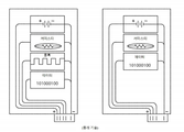
본 발명의 다른 양상은, 암호화 보안 잠금으로 턴오프될 수 있다는 것이다. 우리가 사용한 예시는, TSA 및 안전 기관(safety organizations)이지만, 이는 배터리 수명을 절약하고 추가적인 정보를 활성화하는 제조 및 다른 애플리케이션들에서도 작동할 것이다. 도 1은, 리니어 테크놀러지사(Linear Technologies)에 의해, 시스템이 한 번에 각 셀의 배터리들을 모니터링하고 어드레싱 가능한 부품(addressable part)인, 종래 기술의 일 실시예를 도시한다. 종래 기술에서, 우리는, 외부적으로 전력 공급되고(powered externally) 외부적으로 모니터링되는 단일 셀 시스템(single cell system), 또는 시스템들 모니터링을 가능하게 하는 부품들 중 어느 하나를 목격한다. 이런 타입들의 시스템들은, 그들이 모니터링하는 데이터 및 그들이 제어되는 방식에 있어 제한된다.Another aspect of the invention is that it can be turned off with an encryption security lock. The examples we used are TSA and safety organizations, but this will also work in manufacturing and other applications that save battery life and enable additional information. FIG. 1 shows an embodiment of the prior art, by Linear Technologies, where the system monitors and addresses the batteries of each cell at a time, as an addressable part. In the prior art, we witness either a single cell system that is externally powered and externally monitored, or components that enable monitoring of the systems. Systems of these types are limited in the data they monitor and the way they are controlled.
도 1은 시스템 레벨 설계를 위해 종래 기술로서 각 셀 전압을 모니터링하는 리니어 테크놀러지사(Linear Technology)로부터의 배터리 모니터의 종래 기술 실시예를 도시한다.
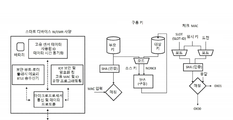
도 2는 강화된 동작을 위한 다수의 센서 및 다수의 스위치를 포함하는 배터리 모니터 및 제어 시스템의 일 실시예를 도시한다.
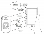
도 3은 보안 NFC 및 암호화 가능 통신(crypto enabled communications), 데이터의 재프로그래밍 및 기입의 일 실시예를 도시한다.
도 4a 및 도 4b는 상단에 또는 측면에 NFC 코일을 갖는 기존의 배터리 조립체로의 모니터링 및 제어 시스템의 기계적 연결 수단의 일 실시예를 도시한다.
도 5는 배터리 모니터 시스템에 대한 적시 등록(just in time registration) 및 암호화 보안을 갖는 보안 네트워크의 일 실시예를 도시한다
도 6은 프로그래밍되어 칩 내에 위치된 내장 키(built in key)와 비교될 키를 전달하기 위해 사용되는 암호화 칩(crypto chip)을 도시한다.
도 7은 패턴들을 찾고 패턴들과 이벤트들을 매칭시켜 문제들을 추적하고 액션들을 분석하는 시스템의 예시를 도시한다.
도 8은 수명 동안 사용 및 변화에 대한 더 나은 관점을 얻기 위해 다수의 작업 흐름으로부터의 데이터 조합을 도시한다.
도 9는 이 데이터 저장 방법이 시간 경과에 따라 데이터를 기록하고 해당 데이터를 어큐뮬레이터 빈들(accumulator bins)에 축적하도록 설계된 어큐뮬레이터 매트릭스를 도시한다. 이는 해당 배터리의 수명과 이력에 대한 3D 관점의 표현이다.
도 10은 종래 시스템들이 각자의 배터리 각각을 판독하기 곤란한 시간을 갖는 병렬 배터리 네트워크를 도시한다.
도 11은 전체 분포의 팁들 및 테일들(tips and tails) 백분위수를 추적하기 위한 다양한 파라미터들, 이벤트들 및 사용 이력의 분포들을 추적하는 배터리 점수화 및 순위화 시스템(battery scoring and ranking system)을 도시한다.
도 12는 요청 시 배터리로부터 공유되는 ID 및 프로토콜의 예시를 도시한다.
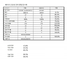
도 13은 배터리 관리 모니터링 및 추적 시스템(battery care monitoring and tracking system)의 일 실시예를 도시한다. 배터리 제조업체는 각 상호작용 및 이벤트를 추적하여 이들 이벤트를 점수화하고 추적하길 원할 수 있다.
도 14는 보안 데이터 통신 및 제로 전력 인터페이스(zero power interface)를 가능하게 하는 제1 시스템 및 데이터를 모니터링하기 위한 제2 시스템을 판독하고 구성하기 위한 듀얼 포트 메모리를 갖는 ASIC 칩 설계를 도시한다.
도 15는 광 전력 공급되는 식별 칩(photo powered identification chip)에 대한 칩 레이아웃을 도시한다. 이 칩은 전력을 위해 변조된 레이저 LED(modulated Laser LED)를 사용하여 IR 또는 RF로 통신할 수 있다.
도 16은 NFC 및 P-칩 프로토콜을 위한 통신 포맷 및 변조의 일 실시예를 도시한다.
도 17은 NFC 배터리 데이터를 판독한 후에 플런저(plunger)로 하여금 배터리를 컨베이어로부터 빈으로 푸시하는 것을 가능하게 함으로써 빈 분류(bin sorting)을 가능하게 하는 배터리 분류 시스템을 도시한다.
도 18은 배터리 유효성을 판독하고 필요에 따라 이들 배터리를 턴온하고 턴오프하는 보안 영역의 일 실시예를 도시한다.
도 19는 IR 송신기 및 RF 송신기로서 사용되는 P-칩을 도시한다.
도 20은 다양하게 프로그래밍될 수 있는 모드들을 가능하게 하는 배터리 명령들(commands) 및 제어 구조(control structure)를 도시한다.
도 21 내지 도 23은 리튬 이온 배터리의 패키징(packaging)으로 제조된 배터리 모니터용 컨트롤러 칩의 다양한 도면들을 도시한다.
도 24 및 도 25는 파우치 열기 밀봉 영역(pouch heat seal area)을 포함하는 리튬 이온 배터리의 패키징을 도시한다.
도 26은 납축 배터리(lead acid battery) 내의 밀봉된 배터리 모니터들을 도시한다.
도 27은 각 태그가 중재 로직(arbitration logic)에 의해 결정된 바와 같이 이용 가능한 정보에 상이한 액세스를 하는 듀얼 주파수 태그 구성을 도시한다.1 shows a prior art embodiment of a battery monitor from Linear Technology that monitors each cell voltage as prior art for system level design.
2 shows an embodiment of a battery monitor and control system including multiple sensors and multiple switches for enhanced operation.
3 shows an embodiment of secure NFC and crypto enabled communications, reprogramming and writing of data.
4A and 4B show one embodiment of a mechanical connection means of a monitoring and control system to a conventional battery assembly with an NFC coil at the top or side.
5 shows an embodiment of a secure network with just in time registration and encryption security for a battery monitor system.
Figure 6 shows a cryptographic chip that is programmed and used to convey a key to be compared to a built-in key located within the chip.
7 shows an example of a system for finding patterns and matching patterns and events to track problems and analyze actions.
8 shows a combination of data from multiple workflows to get a better view of usage and change over life.
Fig. 9 shows an accumulator matrix designed for this data storage method to record data over time and accumulate that data in accumulator bins. This is a 3D view of the battery's life and history.
Fig. 10 shows a parallel battery network in which conventional systems have a difficult time reading each of their batteries.
FIG. 11 shows a battery scoring and ranking system that tracks distributions of various parameters, events and usage history for tracking the tip and tails percentile of the entire distribution. do.
12 shows an example of the ID and protocol shared from the battery upon request.
13 shows an embodiment of a battery care monitoring and tracking system. Battery manufacturers may want to track and track each interaction and event.
14 shows an ASIC chip design with dual port memory to read and configure a first system to enable secure data communication and a zero power interface and a second system to monitor data.
15 shows a chip layout for a photo powered identification chip. The chip can communicate with IR or RF using modulated laser LEDs for power.
16 shows an embodiment of communication format and modulation for NFC and P-chip protocols.
17 shows a battery sorting system that enables bin sorting by enabling a plunger to push a battery from a conveyor to a bin after reading NFC battery data.
18 shows one embodiment of a secure area that reads battery validity and turns these batteries on and off as needed.
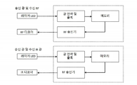
19 shows a P-chip used as an IR transmitter and an RF transmitter.
20 shows battery commands and control structures that enable various programmable modes.
21 to 23 show various views of a controller chip for a battery monitor manufactured by packaging a lithium ion battery.
24 and 25 show packaging of a lithium ion battery comprising a pouch heat seal area.
26 shows sealed battery monitors in a lead acid battery.
27 shows a dual frequency tag configuration where each tag has different access to available information as determined by arbitration logic.
이하, 본 발명의 예시적인 실시예들을 상세하게 참조할 것이고, 그 예시들은 첨부 도면들에 도시되어 있다. 다른 실시예들이 활용될 수 있고 본 발명의 각자의 범주를 벗어남 없이 구조적이고 기능적인 변경들이 이루어질 수 있음을 이해해야 한다. 또한, 다양한 실시예들의 특징들은 본 발명의 범주를 벗어남 없이 결합되거나 변경될 수 있다. 이와 같이, 다음의 설명은 단지 예로서 제시되고, 여전히 본 발명의 사상 및 범주 내에 있는 도시된 실시예에 대해 이루어질 수 있는 다양한 대안 및 수정이 임의의 방식으로 제한되지 않아야 한다.Hereinafter, exemplary embodiments of the present invention will be described in detail, and examples thereof are illustrated in the accompanying drawings. It should be understood that other embodiments can be utilized and structural and functional changes can be made without departing from the respective scope of the invention. Also, features of various embodiments may be combined or changed without departing from the scope of the present invention. As such, the following description is presented by way of example only, and various alternatives and modifications that may be made to the illustrated embodiment that are still within the spirit and scope of the invention should not be limited in any way.
도 2는 배터리 모니터(10)의 시스템 다이어그램을 도시한다. 시스템은, 후술하는 바와 같이, 모니터 상에, 또는 칩셋 내에 포함된 수많은 구성 요소들을 포함할 수 있다. 모니터(10)는, 일반적으로 배터리에, 예를 들어, 배터리의 하나 이상의 단자들에서 연결되어, 배터리의 상태들을 모니터링하고, 일부 경우에, 원치 않는 상태들(unwanted conditions)에 대한 안전 수단(safeguard)을 제공하도록 구성될 수 있다.2 shows a system diagram of the
배터리 모니터(10)는 하나 이상의 센서(12)를 포함할 수 있다. 센서들(12)은 모니터(10)에 연결된 배터리(13)의 적어도 하나의 파라미터를 각각 감지하도록 구성될 수 있다. 센서들(12)은 온도 센서, 전압 센서, 전류 센서, 쿨롬 센서 등과 같은 배터리 상태를 감지하기 위한 임의의 적절한 타입의 센서일 수 있다.The battery monitor 10 may include one or
센서들(12)은 컨트롤러(14)에 대한 입력들로서 기능할 수 있다. 컨트롤러(14)는 후술하는 바와 같이 임의의 적절한 마이크로컨트롤러일 수 있다. 컨트롤러(14)는 센서들을 모니터링하고 센서들에 의해 제공된 데이터를 기록하고, 일부 경우에, 원치 않는 상태들을 방지하기 위한 안전 수단을 제공하도록 구성될 수 있다. 컨트롤러(14)는 하나 이상의 송수신기(16) 및 하나 이상의 안테나(18)에 의해 촉진되는 하나 이상의 통신 인터페이스로 구성될 수 있다. 송수신기들(16)은 특수 동작들 및 네트워크 기능들을 위한 BTLE 및 지그비 메시(BTLE and Zigbee Mesh) 송수신기들을 포함할 수 있다. 안테나(18)는 메시 안테나, BLE 안테나 및/또는 임의의 다른 적절한 안테나를 포함할 수 있다. 통신 인터페이스들은 컨트롤러 칩(14) 상에 온-보드로(on board) 제공되거나 별도의 칩(16) 상에 제공될 수 있다. 예를 들어, 컨트롤러(14)는, 컨트롤러에 독립적인 전력을 제공하도록 더 구성될 수 있는 무선 통신 인터페이스를 포함할 수 있다. 무선 통신 인터페이스는 근거리 통신("NFC") 인터페이스 등과 같은 일종의 무선 주파수 식별("RFID") 통신 인터페이스일 수 있다. NFC 인터페이스는, RF 신호를 수신하기 위한 NFC 코일(20)을 포함할 수 있고, RF 신호가 코일(20)에 의해 수신될 때 컨트롤러에 독립적으로 전력 공급하도록 구성될 수 있다. 컨트롤러(14)는 단일 유선 통신 연결과 같은 유선 연결(22)을 더 포함할 수 있다. 일 실시예에서, 모니터는 배터리가 방전 및 충전되는 동안 배터리의 온도 판독을 가능하게 하는 온도 센서(12)를 포함한다. 컨트롤러(14)는 온도가 사전 결정된 임계값에 도달할 때와 같이 잠재적으로 불안전하거나 원치 않는 상태를 결정하기 위해 온도를 모니터링하는 제1 레벨의 보안으로 활성화될 수 있다. 그 후, 컨트롤러(14)는 원치 않는 상태를 방지하기 위해 후술하는 바와 같이 출력을 작동시킴으로써 동작할 수 있다.The
센서들(12)은 고 정밀 전압 측정(high precision voltage measurement)을 수집하기 위한 회로를 포함할 수 있다. 이 센서 회로는, 배터리 단자들에서와 같이 교정 및 기준 기반의 측정을 가능하게 하기 위해, 저 전압 및 고 전압의 내장 전압 기준값들(built in voltage references)을 활용한다. 판독값들은 컨트롤러(14)에 의해 통계적으로 평균화될 수 있고, 측정된 기준값들로부터의 오프셋들로 참조될 수 있다. 매우 정확한 A/D 레지스터들이, 다수의 12 비트 A/D 변환기를 캐스케이딩(cascading)함으로써 사용될 수 있다. 이들은 온도 및 전압으로 인한 작은 변화들이 보상되도록 허용함으로써 추가적인 정확성을 위해 레퍼런스 전압 기준값들과 함께 사용된다. 고분해능 A/D 변환기들은 분류기(shunt)로서 동작하는 스위치에 걸린 저항을 계산하고 전류를 측정하기 위해 사용된다. 쿨롬은 분류기에 걸린 정확한 전압을 사용하여 시간 경과에 따라 계산된다. 시간 경과에 따른 전류는 충전 및 방전에 대한 쿨롬을 나타낸다. 초 당 1 쿨롬은 1 암페어(Amp)이고, 1C 충전 또는 방전을 나타낸다. 쿨롬을 카운팅함으로써, 마이크로컨트롤러(14)는 배터리의 충전 상태를 추정할 수 있다. 배터리 수명이 이 기술의 제1 애플리케이션으로서 제공되어 있지만, 동일한 이 기술이 슈퍼 커패시터들(super capacitors)에 사용될 수 있다. 시간 경과에 따라 쿨롬을 관찰하는 것은, 배터리 용량의 이미지를 구축한다. 시간 경과에 따라 이 이미지를 관찰하는 것은, 우리로 하여금 변화들을 재활용을 위해 목격하고 사용량 임계값들을 설정하는 것을 가능하게 한다.The
배터리 모니터(10)는 전력 관리(power management)(24)를 포함할 수 있다. 전력 관리(24)는 일반적으로 배터리 모니터의 모든 구성 요소들에 대해 검증된 전압 레벨들을 제공할 수 있다. 전력 관리(24)는 0.2 VDC까지 하나의 셀 동작을 가능하게 하는 에너지 수급을 위한 벅 부스트 변환기(buck boost converter)를 가능하게 할 수 있다. 일 실시예에서, 선택적인 배터리 셀(optional battery cell)(32)은 특수 목적 배터리들을 위해 모니터에 전력 공급하기 위해 전용될 수 있다. 셀(32)은 NFC 필드가 존재할 때뿐만 아니라 항상 전력을 보장하기 위해 모니터(10)에 전용 전력을 제공할 수 있다. 이는 엔지니어링 및 데이터 수집 목적을 위한 모니터링 셀(monitoring cell)일 수 있다. 컨트롤러(14)는 FLASH로 활성화될 수 있어, 그것은 보안적으로(securely) 재프로그래밍될 수 있다. NFC 프로토콜 및 토큰들은 보안을 가능하게 하고, 일련 번호와 같은 기타 데이터가 더 먼 거리에서 판독되도록 제2 RFID 고주파 프로토콜로 제시될 수 있다. 고주파 통신으로 설계된 NFC 통신의 보안이 주어지면, NFC는 컨트롤러(14)에 기입하기 위해 활성화되는 유일한 통신일 수 있다.The battery monitor 10 may include
일 실시예에서, 모니터(10)는 전원(source power)으로부터 분리될 때에도 기능하도록 구성될 수 있고, 여전히 제어되며, 도면들은 요청 시 무전압 상태인(de-energized) 전력 관리로의 스위치를 도시한다. 이 모니터는, 우리가 더 많은 것을 학습할수록 다양한 사용자들이 더 많은 것을 학습하여 데이터를 분석함에 따라, 전세계적으로 통신하고 업데이트할 수 있도록 설계되어 있다.In one embodiment, the
모니터(10)는 컨트롤러(14)에 의해 제어되도록 구성되는 하나 이상의 출력을 포함할 수 있다. 컨트롤러(14)는, 원치 않는 상태가 검출될 때, 배터리 또는 셀을 선택적으로 방전(selectively drain)시키기 위해 배터리 또는 셀의 단자들 사이에서 개방되거나 폐쇄될 수 있는 자가-방전 저항 스위치(self-discharge resistor switch)(26)를 제어할 수 있다. 모니터(10)는 일련의 배터리들 또는 셀들이 전력의 완전 손실(complete loss)을 회피하기 위해 직렬로 연결될 때와 같이, 원치 않는 상태가 검출될 때, 배터리 또는 셀을 우회(bypass)하기 위한 바이패스 스위치(bypass switch)(28)를 포함할 수 있다. 모니터는 전력 관리(24)로부터 입력된 전력을 선택적으로 제어하기 위한 전력 관리 스위치(power management switch)(30)를 포함할 수 있다. 이들 스위치 각각은 컨트롤러에 의해 제어될 수 있고, 아래에 더 논의되는 바와 같이, 감지된 다양한 상태들에 기초하여 활성화되거나 비활성화되도록 프로그래밍될 수 있다.The
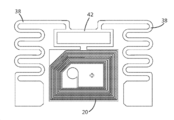
일 실시예에서, 컨트롤러(14), 및/또는 모니터(10)의 구성 요소들은, NFC 통신 필드(NFC communication field)에 의해 전력을 공급받을 수 있다. NFC 필드가 존재할 때, NFC 코일은, 전력을 수신할 수 있고, 컨트롤러로 하여금, NFC 메모리에 기입하는 것에 의해서와 같이, 특정 기능들을 수행하도록 프로그래밍되는 것을 가능하게 할 수 있다. 고주파 칩이 판독될 때, 그것은 결정된 바와 같이 특정 프로그래밍된 액세스로 동일한 메모리에 액세스한다. 이는 단지 해당 셀의 SKU 또는 일련 번호 데이터일 수 있다. 이 메모리는, 컨트롤러(14)로 하여금, 이런 변화를 목격하게 하고 그의 동작 또는 프로그래밍을 재구성하는 것을 가능하게 하도록 듀얼 포트로 되어 있을 수 있다. 이것의 예시는 생산 시에 NFC로 기입하여 자가-방전을 모니터링하는 것이다. 그 후, 모니터(10)는 전력이 방출될 때까지 시간 경과에 따라 데이터를 소비하고 로깅(logging)한다. 동일한 타입의 NFC 기입은 재활용 및 파쇄를 위해 자가-방전 저항(26)을 활성화할 수 있다. 그것은 배터리를 방전시키기 위해 첫 번째로 활성화되고, 그런 다음 NFC는, 배터리가 방전된 후에 자연적으로 전압을 증가시키고 잠재적으로 에너지 위험이 될 경우 화재를 방지하기 위해 파쇄 전에 전압을 판독하는 데에 사용된다. 마이크로컨트롤러(14)로부터의 다른 명령은 바이패스 스위치(28)를 폐쇄하여 배터리를 외부적으로 단락시키고 내부적으로 개방시킬 수 있다. 이런 검사 상태에서, 데이터는, 재고 저장고를 걸어다니는 것(walking the inventory storage)과 같은 거리로부터 검사 결과들을 판독하기 위해, 고주파 태그에 제시되도록 프로그래밍될 수 있음에 주목해야 한다. 본 명세서에서 사용된 바와 같이, 용어 태그는, 안테나 또는 코일뿐만 아니라, 코일에 연결된 칩 또는 반도체도 지칭할 수 있다. 도 27에 도시된 바와 같이, 모니터(10)는, NFC 통신 및 고주파 통신이 모두 가능하도록, 고주파 태그(38) 및 NFC 코일(20) 둘 다를 포함할 수 있다. 도 27은 하나의 칩(42)에 연결된 2개의 태그 안테나들(20, 38)를 도시한다. 칩(42)은 사실상 2개의 칩이 결합된 것이고, 어느 하나의 태그가 사용되는 것을 허용한다. 메모리 중재 컨트롤러(memory arbitration controller)는, 각 통신 수단이 사용 사례 중 임의의 단계, 즉, 생산, 제조, 재사용, 재활용, 검사 및 문제해결에서, 원하는 대로 통신하도록 허용한다. 고주파 통신을 통해 모니터에 허여된 액세스가 제한될 수 있다. 예를 들어, 고주파 통신은, 모니터를 프로그래밍하는 것이 고주파 통신으로부터 선택사항은 아니도록, 컨트롤러(14)로의 액세스를 제한할 수 있다. 다른 예에서, 고주파 통신은 이전에 수집된 데이터에 액세스하는 것으로 제한될 수 있다. 이는 고주파 통신을 통해 데이터의 신속한 수집을 허용할 수 있고, 반면에 NFC 통신은 배터리(13)로부터 어떤 기생 전력 인출도 허용하지 않을 수 있다. 태그 판독기는 클라우드에 연결되고 인스턴트 검사 데이터(instant test data)를 클라우드 데이터베이스에 제시한다.In one embodiment, the components of the
컨트롤러(14)는 단일 유선 어드레싱 가능한 네트워크 인터페이스(22)를 갖는다. 그것은 I2C 인터페이스일 수 있고, 명령 세트(command set)는 주소들 및 각 배터리와 연관된 데이터를 보고할 수 있다. 일 실시예에서, 센서들(12)은 충격(shock) 및 움직임 이벤트들을 모니터링하기 위한 가속도계(accelerometer)를 포함한다.The
NFC 코일(20)은, NFC 코일(20) 아래에 소량의 페라이트(ferrite) 또는 가압된 절연 철(isolated pressed iron)과 함께 배터리의 캡(cap) 상에, 또는 측면(도 4a 및 도 4b에 도시된 바와 같이)에 장착되어 양호한 NFC 판독(read) 및 기입(write)을 가능하게 할 수 있다. 페라이트 또는 가압된 절연 철은 금속 상에 장착되는 저주파 및 고주파 태그들에 대해 동작한다. 이는 배터리 또는 단자 금속으로부터 코일(20)을 절연함으로써 달성된다.The
도 3은 특정 데이터 및 데이터 세그먼트들에 대한 채널들을 개방하기 위해 NFC 프로토콜을 사용하여 모니터(10)를 보안적으로 판독하고 검증(validating)하는 프로세스를 도시한다. 예를 들어, 모바일 디바이스(36)는 NFC 기능(NFC capabilities)을 가질 수 있고 배터리 모니터(10)와 통신 가능하게 될 수 있다. 모니터(10)에 대한 지정된 혹은 제한된 액세스, 및 그의 기능들은 다른 당사자들에게 주어질 수 있다. 예를 들어, 제조업체는 특정 액세스(specific access)를 가질 수 있고, OEM은 특정 액세스를 가질 수 있고, 재활용업자는 특정 액세스를 가질 수 있고, 제2 사용자는 특정 액세스를 가질 수 있다. 각각의 판독으로, 제조업체는, 이 데이터가 동일한 방식으로 수집되기 때문에, 필드로부터 학습되어 이해된 임계값들과 새로운 펌웨어를 이용하여 배터리(13) 내의 펌웨어를 업데이트할 수 있다. 모니터(10) 및 인증 애플리케이션의 암호화 코드는 로깅된 데이터(logged data)를 판독할 때 보안 핸드쉐이크(secure handshake)를 가능하게 한다. 애플리케이션은, 이 채널을 활용하여 로깅된 데이터를 우리의 데이터베이스에 전송하여, 시간 경과에 따라, 그리고 각 사용자에 대한 또는 그 수명 전체 동안의 사용에 대한 통계와 학습을 가능하게 할 수 있다. 도 3에 도시된 바와 같이, 검증 프로세스는 NFC 필드가 모바일 디바이스(36) 상에서 전력 공급(powered up)될 때 시작될 수 있다. 모니터(10) 상의 NFC 송수신기(16)는 ID 및 암호화 코드를 갖는 필드에 응답할 수 있다. 모바일 디바이스(36) 상의 모바일 애플리케이션과 같은 소프트웨어는, 검증이 이루어지는 인터넷 상의 지정된 주소(specified address)로 ID를 전송할 수 있다. 그 후, 애플리케이션은, ID 및 암호화 코드를 수신할 수 있고, 모니터(10)를 코딩하기 위해 그것을 NFC 송수신기(16)에 다시 전달한다.3 shows a process for securely reading and validating the
도 4a는 배터리 캡(40)에 연결된 모니터의 사용을 도시한다. 컨트롤러(14)는, 활성화될 때 배터리(13)를 통해 전력이 공급되거나, 판독될 때 NFC 필드에 의해 전력이 공급된다. 도 4b는 컨트롤러(14)가 여전히 캡(40) 상에 위치되지만 코일(20)이 셀의 측면에 위치되는 측면 장착 버전을 도시한다. 이들 코일(20)은 통신을 보장하기 위해 공간, 또는 페라이트 또는 가압된 절연 철 중 어느 하나로 금속으로부터 절연될 수 있다. 단순 플라스틱 캡(simple plastic cap)은 캡에 충분한 공간을 제공하여 양호한 NFC 판독들을 가능하게 할 수 있다. 이 이미지는 저주파 태그만 도시하지만, 추가적인 유연성을 위해 저주파 태그와 고주파 태그 둘 다 사용될 수 있다. 이는 도 27에서 참조된다.4A shows the use of a monitor connected to the battery cap 40. The
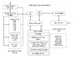
도 5는 모니터(10)와 함께 AWS("Amazon Web Services") 및 적시 등록(Just In Time Registration)을 활용하는 방법을 도시한다. 이 방법은, 디바이스들, 애플리케이션들을 연결하고, 검증 및 보안 펌웨어 개정 제어(validation and secure firmware revision control)를 위해 모바일 이미지 및 섀도우 디바이스(mobile image and shadow device)를 유지함으로써 소프트웨어를 관리하는 데에 도움이 된다. 이 시스템은, 확장 가능하며, 일단 서버없는 프레임워크(serverless framework)가 설정되면 쉽고 간단하게 전세계적으로 이용될 수 있다. 아트멜 사의 암호화 칩(Atmel Crypto chip)은, 도 6에서 목격되는 바와 같이, IOT 펌웨어를 업데이트하기 위한 추가적인 암호화 보안을 위해 활용될 수 있다. 도시된 바와 같이, 대상 키(target key)가 제시될 때 키가 전달된다. 매칭이 이루어지면, 보안 파이프 라인이 생성된다. 이는 판독, 재사용, 또는 재작업 시에, 실시간으로 배터리들을 모니터링하기 위해 사용될 수 있는 보안 네트워크를 가능하게 한다.5 shows how to utilize AWS ("Amazon Web Services") and Just In Time Registration with the
도 7은 문제들을 표면화하고 문제들에 대한 잠재적인 해결책들을 가능하게 하기 위해 사용될 수 있는 패턴 매칭 및 변칙 추적(anomaly tracking)의 방법을 도시한다. 데이터, 활동들, 사회 집단들, 질병 상태들, 효과들 및 부작용들에서 패턴을 발견하는 것은, 데이터셋(dataset)에서 중요도(level of importance)를 식별하는 데에 도움이 된다. 컨트롤러(14)에 의해 수집된 데이터는, 패턴들 및 상태들을 인식하도록 모니터링될 수 있다. 다양한 조건 하에, 통신을 통해 네트워크로 전송된 사전 프로그래밍된 메시지들이 식별된 당사자에게 통지될 수 있다. 컨트롤러(14)에 의해 수신된 데이터의 통신 및 로깅을 가능하게 하는 일련의 패턴들이 사전 로딩되고 트리거들이 설정된다. 모니터(10)는, 업데이트 시간 또는 이벤트, 및 전체 상시 모니터링(full always on monitoring)을 기입하기 위해, NFC에 의해 판독될 때, 전체로부터 결정적 데이터를 로깅 오프하여 저장하기 위해 프로그래밍될 수 있는 수개의 전력 모드(several programmable power modes)를 갖는다. 트리거들 및 액션들은 특정 효과들과 함께 프로그래밍되고, 모니터링 조건(monitoring conditions)이 설정된다.7 shows a method of pattern matching and anomaly tracking that can be used to surface problems and enable potential solutions to problems. Discovering patterns in data, activities, social groups, disease states, effects and side effects helps to identify the level of importance in the dataset. Data collected by the
도 8은 다양한 사용 사례들 및 사용자들에 대한 작업 흐름(work flow)이 추적되는 방법의 예시를 제공한다. 전형적으로, 배터리들은 일차 제조업체와는 별도로 추적되고, 배터리는 그 후 다시 OEM에 의해 구현 시, 다시 패키징되고 검사되며, 재작업 및 재활용 시에 또 다시 패키징되고 검사될 수 있다. 일 실시예에서, 셀의 수명 동안 이 정보를 저장하고 공유하는 방법이 제공된다. 데이터는, 분석 및 기계 산업 학습(machine business learning)을 위해 컨트롤러와 관련 메모리에 의해 수집될 수 있으며, 사양(specifications) 및 사용량(usage)을 개선하기 위해 사용될 수 있다. 이 데이터는 또한, 어떤 화학물질(chemistries)이 최상으로 작동하는지와 어떤 제조 방법이 가장 신뢰할 만한지를 입증하기 위해 사용될 수 있다. 이 방법은 각 특정 기능에 대해 최상의 제조업체들 및 배터리들에 대해 작동할 수 있다. 이 통합된 관점은 적용되는 모든 것에 대한 학습을 제공할 것이다. 제1 보안 및 로컬 통신(예컨대, NFC)은, 상이하게 프로그래밍될 수 있는 상태들에서 데이터가 상이하게 제시되는 보안성 낮은 제2 RFID 액세스를 활성화한다.8 provides an example of how various use cases and work flows for users are tracked. Typically, the batteries are tracked separately from the primary manufacturer, and the batteries can then be packaged and inspected again, upon implementation by the OEM, and again packaged and inspected during rework and recycling. In one embodiment, a method for storing and sharing this information over the life of the cell is provided. Data can be collected by the controller and associated memory for analysis and machine business learning, and can be used to improve specifications and usage. This data can also be used to demonstrate which chemistries work best and which manufacturing method is the most reliable. This method can work for the best manufacturers and batteries for each particular function. This integrated perspective will provide learning of everything that applies. The first security and local communication (eg, NFC) activates a low security second RFID access where data is presented differently in different programmable states.
도 9에는, 어큐뮬레이터 매트릭스가 도시되어 있다. 이는 이 배터리에 대한 사용 강도(intensity of use)를 순위화하거나 점수화하는 것을 가능하게 하는 정보 빈들(bins of information)을 나타낸다. 이 매트릭스는, 배터리의 수명 동안의 수명 결정적 상황들(life critical situations) 및 각 작업 흐름 천이(workflow transition)와 같은 수명 특정 이벤트들을 축적하도록 설계되어 있다. 매트릭스는 이벤트들로서 기록되는 빈들에 기반을 둔 온도와 전하이다. 이 데이터의 분포는 환경 및 애플리케이션 내에서 해당 배터리의 수명과 취급(treatment)에 대한 특징(signature)을 나타낸다. 재사용 및 재활용을 위한 최상의 애플리케이션 및 임계값들을 결정하기 위해서는 하나의 작업 흐름 그 이상의 이런 데이터가 필요하다.In Figure 9, an accumulator matrix is shown. It represents bins of information that make it possible to rank or score the intensity of use for this battery. This matrix is designed to accumulate life-specific events such as life critical situations and each workflow transition over the life of the battery. The matrix is the temperature and charge based on the bins recorded as events. The distribution of this data represents the life and treatment of the battery in question within the environment and application. More than one workflow needs this data to determine the best applications and thresholds for reuse and recycling.
도 10은 병렬 구성 내에서 각 셀이 모니터링되고 추적될 수 있는 병렬 배터리 팩을 도시한다. 각 배터리 또는 셀에 연결된(tied to) 다수의 모니터(10)는 통신 네트워크(50)를 통해 연결될 수 있다. 네트워크는 단일 유선 네트워크, NFC, 또는 DC 버스를 통한 DC 백스캐터(DC backscatter)일 수 있다. 이는 단일 RFID 기술이거나 또는 다수의 저주파 및 고주파 액세스일 수 있음에 주목해야 한다.10 shows a parallel battery pack in which each cell can be monitored and tracked within a parallel configuration. Multiple monitors 10 connected to each battery or cell may be connected through a
도 11은 배터리들의 수명, 사용 심각도(severity of use), 및 경험에 대한 순위화를 가능하게 하기 위한 건강성 점수화 공식(health scoring formula)을 도시한다. 이 분포들은 평가되어, 분포 곡선의 팁들 및 테일들과 함께 평균을 도시한다. 이는 배터리의 수명 특징(signature)을 나타내고, 무엇이 각 배터리 타입(each type of battery)의 수명에 영향을 주는지를 도시한다. 일 실시예에서, 시스템은 더 양호한 배터리를 제작하는 한계들 및 설계 방법들에 대한 더 양호한 이해를 가능하게 하는 수백만 배터리들과 유형들에 대한 데이터베이스를 포함하거나 활용할 수 있다. 대안적인 실시예에서, 데이터는 재활용을 위한 임계값들 및 재사용을 위한 건강성 적합도(fitness of health)를 정의하기 위해 사용될 수 있다. 알고리즘은 내부 저항, 온도, 충전 방전 속도, 수명(age) 및 활동 가속도와 함께 어큐뮬레이터 매트릭스에 액세스하여 이들을 사용하여 건강성 점수를 결정하고 순위화한다. 이는 또한 누가 최고의 배터리를 제작하는지를 정의하고 시간 경과에 따라 어떤 화학물질과 제조 방법이 최상인지를 정의하는 수단이 된다. 이 정보는 이런 프로세스들과 방법들을 개선하기 위해 사용될 것이다.FIG. 11 shows a health scoring formula to enable ranking of batteries for life, severity of use, and experience. These distributions were evaluated to show the mean along with the tips and tails of the distribution curve. It represents the lifespan characteristics of the battery and shows what affects the lifespan of each type of battery. In one embodiment, the system may include or utilize a database of millions of batteries and types that allow for a better understanding of the limitations and design methods of making a better battery. In an alternative embodiment, data can be used to define thresholds for recycling and fitness of health for reuse. The algorithm accesses the accumulator matrix along with internal resistance, temperature, charge discharge rate, age and activity acceleration, and uses them to determine and rank health scores. It also serves as a means to define who makes the best batteries and which chemicals and manufacturing methods are best over time. This information will be used to improve these processes and methods.
도 12에는, 배터리 건강성 및 관리 점수화(battery health and care scoring)의 표현이 도시되어 있다. 이 점수는 배터리가 유지 관리되는 방법을 결정하고, 작업 흐름 내에서 이벤트들 및 서비스 상호작용들을 모니터링하여 누가 배터리와 접촉하는지와, 이것이 또한 수명에 영향을 줄 수 있는 경우, 어떤 목적을 위한 것인지를 도시한다. 형편없이 유지 관리된 배터리(poorly maintained battery)는 재평가(rerated)될 수 있고 반면에 잘 유지 관리된 배터리는 연장된 수명을 가질 수 있다. 도 13은 레지스터들의 바이트 카운트 및 프로토콜을 도시한다. 그것은 배터리 모니터의 수명 동안 보안 데이터 전송을 위한 전송 방법론을 가능하게 하는 일차 및 이차 레지스터들을 도시한다. 이 방법은 일차 레지스터들이 체크섬에 의해 업데이트되고 검증될 때까지 이차 레지스터들을 그대로(in tact) 유지한다. 검증 시, 이차 레지스터들도 업데이트된다. 이 프로세스는 정전(power fail), 판독 또는 기입 오류(read or write error), 전력 사고 또는 재해(glitches in power or accidents)의 경우에 데이터의 무결성(data integrity)을 유지한다.In Figure 12, the representation of battery health and care scoring is shown. This score determines how the battery is maintained and monitors events and service interactions within the workflow to determine who is in contact with the battery and for what purpose, if this can also affect lifespan. City. A poorly maintained battery can be rerated, while a well maintained battery can have an extended life. 13 shows the byte count and protocol of registers. It shows primary and secondary registers that enable the transfer methodology for secure data transfer over the life of the battery monitor. This method keeps the secondary registers intact until the primary registers are updated and verified by a checksum. Upon verification, the secondary registers are also updated. This process maintains data integrity in case of power fail, read or write error, glitches in power or accidents.
도 14는 컨트롤러(14)를 위한 단일 칩 설계용 ASIC 레이아웃을 도시한다. 상기 단일 칩 설계는, 도 2로부터 도시되고 설명된 단일 칩에 대한 복수의 특징들을 포함한다. NFC 컨트롤러는, 온-보드 단일 칩에 포함되고, 컨트롤러(14)와 관련된 설계에 기반한다. NFC는 NFC 가능 제어(NFC enabling control) 및 전형적인 NFC 판독 및 기입을 위해 듀얼 포트의 메모리를 활용할 수 있다. 이 칩은, 이러한 사용에 대한 작업 흐름 및 수명 데이터를 추적하기 위해, 이 문서에 언급된 센서들과 레지스터들의 전부를 통합한다. 중재 인터럽트 로직(arbitration interrupt logic)은 다수의 시스템에의 메모리 액세스를 허용한다. 이 중재 로직은 직접 I2C 프로그래밍(direct I2C programming) 또는 NFC 로컬 통신(NFC local communications)에 의해 프로그래밍될 수 있다. 프로그래밍은, 예를 들어, 우리가 더 먼 거리에 대한 다른 태그 기술 액세스를 추가하는 경우, 시스템이 상이한 포트들에서 무엇이 이용 가능한지를 결정하도록 허용한다. 고주파수 태그들은 다른 액세스를 추가하는 양호한 예시이다. 추가적인 유연성을 위해, 추가적인 I/O 컨트롤러들에 의한 2개의 I/O 제어가 추가될 수 있다. 도 15는 전형적인 NFC 프로토콜에 더하여 백스캐터 통신들을 위한 통신 프로토콜을 도시한다.14 shows an ASIC layout for a single chip design for the
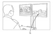
도 17은 생산 시 배터리들을 분류(sorting)하고 판독하기 위한 시스템(60) 및 방법을 도시한다. 이 시스템(60)은 긴 컨베이어(conveyor)(64)가 운반될 때 각 배터리의 NFC 판독을 위해 더 큰 안테나(62)를 사용한다. 안테나는, 충전 빈(charge bin)(66) 또는 폐기물 빈(waste bin)(68)으로와 같이 배터리들을 분류하는 경우, 충전 상태, 수명, 및 타입에 대해 각 배터리를 판독하여, 재사용 또는 재활용 전 모든 데이터를 수집한다. 배터리가 재활용 예정인 경우, 분류 기계(sorting machine)는 출력(output)을 개방하고 파쇄(shredding) 전에 에너지를 제거하기 위해 내부 방전 프로세스를 선택한다. 이 프로세스는, 배터리들이 방전될 수 있지만 그것들이 해당 프로세스 후에 시간 경과에 따라 전압을 구축하기 때문에, 통상적으로 문제들을 야기할 수 있다. 내부 방전 회로는 단순한 재활용 프로세스를 가능하게 한다. 배터리 화학물질(chemistry), 크기, 제조업체 또는 기타 기준에 의한 타입 분류(type sorting)은 매우 단순하다. 도 18a 및 도 18b에서는 보안 목적들을 위해 배터리들을 점검하고 심지어 배터리들이 의도된 대로 제조되었는지 검증하기 위해 이들 배터리를 검사하는 방법을 도시한다. 도 18a는 화면 구역(screening zone) 내에 위치된 NFC 안테나를 통해 상태를 판독함으로써 배터리의 상태를 제공할 수 있는 보안 모니터(70)를 도시한다. 도 18b는, 배터리 상태를 판독할 수 있고, 배터리를 턴오프하는 것과 같이 배터리에 명령을 전송할 수 있는, 화면 구역(72)에 위치된 NFC 안테나를 갖는 컨베이어를 도시한다. 이들 배터리들은, 이송(transportation) 목적이 아닌 경우, 전술된 바와 같이, 내부 스위치들을 암호화 패스워드로 활성화(enabling)시킴으로써, 비활성화될(disabled) 수 있다. 이들 배터리는 위조 모니터링 및 검증(tamper monitoring and validation)과 함께 사후 전송 또는 보안 프로세스 활성화될 수 있다.17 shows a
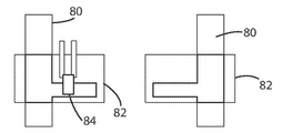
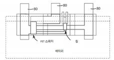
도 21 내지 도 25는 일반적으로 리튬 이온 배터리의 케이싱 내에 제조된 배터리 모니터(10)를 도시한다. 도 21 및 도 22는 열가소성 층(thermoplastic layer)(82)으로 양측이 둘러싸인 전도성 탭(conductive tab)(80)을 도시한다. 이 열가소성 층(82)은 배터리 전해질이 금속 탭에 전달되는 것을 방지하기 위해 밀봉된다. 열가소성 시일(thermoplastic seal)은 또한, 패터(patter)가 전해질을 유지하도록 밀봉될 때 다시 밀봉되도록 설계된다. 칩(84)을 배터리에 밀봉하기 위해, 우리는 이들 탭에 연결할 필요가 있다. 탭 설계 및 스탬핑(stamping)은, 칩(84)을 탭(80)에 접합(bonding)하는 것을 허용하도록 설계된다. 탭(80)이 칩 조립체(chip assembly)를 허용하도록 구성되는 방식은, 제1 열가소성 층이 탭(80)에 접합되어 탭(80)을 제자리에 유지하는 것이다. 필요에 따라, 탭(80)은 회로 기판에 기계적으로 접합될 수 있다. 열가소성(82)은 단순 설계를 위한 회로 기판으로서 역할을 할 수 있다.21 to 25 generally show a
탭(80)은 또한, 용접된 상호 연결부들(welded interconnections) 또는 스냅형 상세부들(snap like details)이 각 전극 탭으로부터 이들 회로를 상호 연결하는 것을 허용하도록 설계된다. 이는, 추가적인 센서들 또는 기타 디바이스들이 배터리 상태들을 감지하는 것을 허용하는 것과 동일한 방식으로, FET 스위치들(86)이 밀봉될 수 있게 한다. 배터리로부터 가져온 더 작은 추가적인 탭들은, 안테나 및 코일 연결부를 위한 것이다. 도면들은 2개의 연결부를 도시하지만, 4개 이상의 연결부가 다수의 입력에 사용될 수 있다.The
비록 도면들이 열가소성에 직접 스탬핑하는 것을 설명하더라도, 캡톤(Kapton)과 마찬가지로 얇은 PCBA가 대안적으로 사용될 수 있다.Although the drawings illustrate stamping directly on thermoplastics, a thin PCBA, like Kapton, can alternatively be used.
2개 또는 3개의 탭이 사용되는 경우, 시스템은 열가소성 상부 층(thermoplastic top layer)을 사용하고 2개의 표를 접합하여 함께 유지하기 위해, 중첩 커넥터 시스템(overlapping connector system)을 활용할 수 있고, 전해질로부터 전체 회로를 밀봉하고 압력을 가하여 상호 연결부들이 스냅 상호 연결부로서 보여지게 할 수 있다.When two or three tabs are used, the system can utilize an overlapping connector system to use a thermoplastic top layer and hold the two tables together to keep them together, and from the electrolyte The entire circuit can be sealed and pressured to make the interconnects appear as snap interconnects.
도 26의 12 VDC 배터리 다이어그램은 각 셀에 위치된 밀봉된 RFID 센서들/모니터들(90)을 도시한다. 플라스틱 외함(enclosure)은 전극들이 각 셀에 연결되는 동안 전자 장치 및 에너지 수급 회로를 보호한다. 설계를 통해 센서들과 RFID가 전해질 내에 위치될 수 있고, 셀로의 상호 연결부들은 배터리 내에서 사용되는 유사한 재료들이 존재하면서 모니터링하는 것을 가능하게 한다. 배터리는 12개, 24개, 48개 또는 더 큰 배터리일 수 있다. 셀 번호는 결정적인 것이 아니지만, 모니터링을 위한 상호 연결부들은 결정적인 것이다.The 12 VDC battery diagram of FIG. 26 shows sealed RFID sensors / monitors 90 located in each cell. A plastic enclosure protects the electronics and energy supply circuitry while the electrodes are connected to each cell. Through the design, sensors and RFID can be located in the electrolyte, and the interconnects to the cell allow monitoring while similar materials are used in the battery. The battery can be 12, 24, 48 or larger batteries. The cell number is not critical, but the interconnects for monitoring are critical.
본 명세서에 설명된 시스템 및 방법의 일 양상에서, 배터리 모니터 및 관련 방법들은 배터리 재활용 목적을 위해 사용될 수 있다. 개시된 모니터 및 방법들은 분류 기능을 가능하게 하기 때문에, 재활용이 더 용이해진다. 분류 기계(도 17)는 셀 조건뿐만 아니라 셀 화학물질(cell chemistries)을 결정하는 경제적이고 신속한 방식(economical and fast way)을 도시한다.In one aspect of the systems and methods described herein, battery monitors and related methods can be used for battery recycling purposes. Since the disclosed monitors and methods enable a sorting function, recycling becomes easier. The sorting machine (FIG. 17) shows an economical and fast way to determine cell conditions as well as cell chemistries.
본 개시의 다른 양상에서, 본 명세서에 설명된 모니터(10) 및 방법들은 제2 수명 애플리케이션들에 사용될 수 있다. 상기 주목된 것과 유사한 분류 프로세스는 화학물질에 의해 분류를 제공할 수 있고, 셀들의 등급화(grading) 추가가 있을 수 있다. 주요 특성들(key characteristics)에 의해 배터리들을 그룹화하는 것이 더 용이해져서, 재제조 및 리퍼포징을 위해 그들이 무료로(in a complimentary manner) 거동하는 것(예를 들어, 그들이 유사한 용량 및 기대 수명 특성들(life-expectancy characteristics)을 가질 것)을 보장한다.In another aspect of the present disclosure, the
본 개시의 다른 양상에서, 모니터(10)는 제조업체에서 배터리들을 초기 생성하는 동안 배터리에 설치될 수 있다. 이는 본 발명이 초기 제조 동안 배터리에 적용되어 재생, 리퍼포징 및 재활용 및 임의의 다른 미래의 애플리케이션에 이용 가능하게 할 수 있어야 하기 때문에 중요하다. 새로운 배터리 산업의 이점은, 현재 셀들이 구축된 뒤에 즉시 정확한 용량(correct capacity)을 결정하기 위해 충전 및 방전된다는 것이다. 본 발명은, 과전압, 직류 저항(direct-current resistance)(DCR) 및 열기/열(heat/thermal)을 모니터링함으로써 개선된 효율을 허용할 것이다. 본 발명의 중요한 이점은, 셀들이 생산 후에 3주 동안 저장되어 고 자가 방전(high self-discharge)(HSD)를 점검할 때 드러난다. 오늘날, 제조업체들은 로봇 장비를 사용하여 이 3주 기간 동안 배터리 전압들을 주기적으로 점검하여 HSD가 발생하지 않음을 보장한다. 이 모니터를 이용하여, 전체 프로세스를 수정할 수 있다. 고비용의 로봇 장비와 인건비(labor costs)가 수반되기 보다는, 셀 당 적은 비용으로, 이것이 훨씬 더 고속으로 효율성 있게 전부 모니터링될 수 있다. 우리는 한번에(at one time) 검사 중인 셀들을 "전부(ALL)" 표시하고/하거나, 설정된 프로그래밍 가능한 파라미터들을 벗어난 셀들만을 표시하는 능력을 제공할 수 있다. 이 단계에서의 비용 절약만으로, 우리의 기술을 그들의 셀들에 통합하는 것에 대한 가외의 비용(extra costs)을 쉽게 정당화할 수 있다. 사용량에 대한, 유사한 배터리들(like batteries)의 분포에 대한 등급화/순위화 및 수명 결정(grading/ranking and life-determination)은 매우 가치 있게 된다.In another aspect of the present disclosure, the
본 개시의 다른 양상에서, 본 명세서에 설명된 모니터(10) 및 방법들은 고-신뢰성-요건 애플리케이션들 및 추적(high-reliability-requirement applications and tracking)에 사용될 수 있다. 이 예시는, 야전병(field soldier)이 작전에 사용할 팩을 선택할 때와 같이, 군사 용도(in military use)로 목격될 수 있다. 본 발명은, (사실상(in effect) 사전 설정된 조건 하에서(under preset conditions) 배터리들이 얼마나 오랫동안 지속될 것인지를 결정하여) 배터리 팩이 완충(fully charged)되고, 필요에 따라 특정 암페어에서 시간 당 용량 인출에 대해 표시할 모니터링 시스템을 제공한다. 그들은 해당 배터리의 수명 경험과 그의 성능 저하 레벨(degradation level)을 목격할 수 있다. 이들 배터리에 대한 수명-순위화 정보(life-ranking information)가 이용 가능하여 재고 제어를 단순화할 것이다. 데이터는, 팩이 있는 그대로 사용될 수 있는지(모든 셀들이 사양에 따라 작동함), 팩을 수리할 것인지(사양들을 충족하기 위해 일부 셀이 교체될 필요가 있을 수 있음) 혹은 팩을 폐기(discard)할 것인지(팩이 사양들을 충족하지 않아 적절한 작업 조건에 도달할 수 없을 것임)를 결정하는 데에, 이용 가능할 것이다.In another aspect of the present disclosure, the
본 개시의 다른 양상에서, 모니터(10)는, 모니터링 기능들을 수행하는 레지스터들을 구성함으로써, 근거리 통신(NFC)을 통해 전력을 공급받을 수 있다. 모니터는 배터리 또는 NFC에 의해 전력을 공급받을 수 있다. 이 시스템은 듀얼 포트의 메모리를 갖고 있어, 두 기능(both functions)이 충분히 동작할 수 있으며 두 기능은 독립적으로 동작할 수 있다.In another aspect of the present disclosure, the
본 개시의 다른 양상에서, 배터리 수명의 수많은 특성들 및 양상들을 판독하기 위해 저비용 배터리 모니터(low-cost battery monitor)를 가능하게 하는 주문형 집적 회로(application-specific integrated circuit)(ASIC) 칩이 사용된다. 이는 보증 결정(warranty determination), 수명, 설치 날짜(date of installation), 제조, 구매 장소(place of purchase), 재주문(reordering), 빠른 전압 점검(quick voltage checks) 및 기타 양상들을 위해 임의의 배터리에 활용될 수 있다. 이는 재충전식 화학물질(rechargeable chemistries), 납축(리워터링 및 관리(re-watering and care)를 가짐), 및 알카라인 및/또는 일차 배터리들에 사용될 수 있다. 이 정보와 함께, 안전 메커니즘이 직렬 구성인 셀을 단락(short-circuit)시키거나 병렬 구성인 셀을 개방하기 위해 사용될 수 있다. 이는, 정의된 파라미터들을 벗어날 수 있는 임의의 셀들을 비활성화하면서, 배터리 또는 모듈이 계속 기능하는 것을 허용할 수 있다. 단일 배터리 셀에서, 이 정보는 해당 셀이 비활성화되는 것을 허용하여 그것이 전원 공급하는 제품을 보호하게 할 수 있다.In another aspect of the present disclosure, an application-specific integrated circuit (ASIC) chip is used that enables a low-cost battery monitor to read numerous characteristics and aspects of battery life. . It can be used with any battery for warranty determination, lifetime, date of installation, manufacturing, place of purchase, reordering, quick voltage checks and other aspects. Can be utilized. It can be used for rechargeable chemistries, lead acid (with re-watering and care), and alkaline and / or primary batteries. With this information, a safety mechanism can be used to short-circuit cells in series or open cells in parallel. This can allow the battery or module to continue functioning while deactivating any cells that may escape defined parameters. In a single battery cell, this information can allow that cell to be deactivated, thereby protecting the product it supplies.
본 개시의 다른 양상에서, 배터리의 작업 흐름 및 수명 내에 상이한 순간들에 턴온 및 턴오프될 수 있는 검사 프로세스를 가능하게 하는 통신 방법이 제공된다. 이는, 재활용 프로세스를 통해 셀 단위로(on a cell by cell basis) 데이터 수집을 가능하게 할 것이고, 지금 현존하지 않는(non-existent) 연구 개발(R&D) 피드백 기회를 허용할 것이다.In another aspect of the present disclosure, a communication method is provided that enables an inspection process that can be turned on and off at different moments within the working flow and life of a battery. This will enable data collection on a cell by cell basis through a recycling process and will allow non-existent research and development (R & D) feedback opportunities.
본 개시의 다른 양상에서, 본 명세서에 설명된 모니터(10) 및 방법들은 시장의 기존 제품들에 적용된다. 이는, 액세스 가능할 때 개별 셀들에 적용될 수 있거나, 개별 셀 액세스가 획득될 수 없을 때 셀들의 그룹/모듈/팩에 적용될 수 있다.In another aspect of the disclosure, the
본 개시의 다른 양상에서, 다양한 전자 디바이스들 및/또는 부품들에 본 발명을 적용한 것이 제공된다. 이는, 디바이스 내의 다양한 전자 부품들에 인가되는 전압 및 인출 전류량을 측정하기 위해 사용될 수 있다. 데이터는, 디바이스 내에서 근본-원인 분석 실패들(root-cause analysis failures)을 결정하기 위해 사용될 수 있다.In another aspect of the present disclosure, application of the present invention to various electronic devices and / or components is provided. It can be used to measure the amount of voltage and draw current applied to various electronic components in the device. Data can be used to determine root-cause analysis failures within the device.
다른 양상에서, ICC는 밸런스 브리드 저항(balance bleed resistor)으로서 기능하는 방전 저항과 함께 설정된 포인트 능력들(set point capabilities) 및 모니터(10)를 사용함으로써 배터리 시스템을 위한 밸런서(balancer)로서 사용될 수 있고, 이 유닛은 무선 밸런싱 네트워크로서 동작한다. 밸런서들 중 하나가 고장나는 경우, 배터리 안전성을 가능하게 하면서, 우리는 모니터의 소프트웨어를 사용하여 더 이상 보고하지 않는 유닛에 대해 그룹 내의 알려진 보고 밸런서들의 전압 차를 계산하고, 이에 의해 알려진 총 전압 합계 및 누락 차이(the known total voltage sum and the missing difference)를 계산하여, 우리가 여전히, 최상의 저항성을 보장하거나 심지어 시간 경과에 따라 해당 저항성을 전환하는 안전한 레벨에서 동작하는지를 목격할 수 있다.In another aspect, the ICC can be used as a balancer for a battery system by using set point capabilities and monitor 10 along with a discharge resistor that functions as a balance bleed resistor and , This unit operates as a wireless balancing network. When one of the balancers fails, enabling battery safety, we use the monitor's software to calculate the voltage difference of the known reporting balancers in the group for the unit no longer reporting, and sum the total voltages known thereby And by calculating the known total voltage sum and the missing difference, we can still see if it works at a safe level that guarantees the best resistance or even switches that resistance over time.
본 개시의 다른 양상에서, 본 명세서에 개시된 모니터(10) 및 관련 방법들은 배터리들의 운송 및 수송 안전에 적용될 수 있다. 수송 동안 셀들을 모니터링함으로써, 정보가 중앙 배터리 관리 시스템(central battery management system)(BMS)에 전송되어, 운전자들, 검문소들/화물 트럭 운영자들(scale operators), TSA 대리인들, 공공 서비스 위원회 책임자들 또는 임의의 다른 책임 있는 당사자에게 정보를 제공할 수 있다. 이는 발생할 수 있는 불안전 상태들, 및/또는 배터리들이 안전한 운송 파라미터들 내에 있는지를 보고할 수 있다. BCM과 함께 셀 배터리 관리 시스템(cell battery management system)(CBMS)은 제공된 정보의 성능과 품질을 향상시킬 것이다.In another aspect of the present disclosure, the
다른 양상에서, 다양한 기능들을 나타내는 다수의 인터페이스를 갖는 것이 더 큰 기능들을 형성한다. 저주파 통신은 저렴하며 직접 모니터링을 위해 시스템들에 구현될 수 있다. 고주파 태그들은 덜 비싸지만, 송신기들은 더 비싸며 생산 및 제조 해결책에는 더 적합하다. 이들 시스템과, 듀얼 포트이며 프로그래밍될 수 있는 메모리의 조합체는, 회로 모니터링, 제품 검사, 재활용 분류 및 전체 유연성에 있어 기술자들에게 적합한 해결책을 제공한다.In another aspect, having multiple interfaces representing various functions forms larger functions. Low frequency communication is inexpensive and can be implemented in systems for direct monitoring. High-frequency tags are less expensive, but transmitters are more expensive and more suitable for production and manufacturing solutions. The combination of these systems and dual-port, programmable memory provides a suitable solution for technicians in circuit monitoring, product inspection, recycling classification and total flexibility.
"수직", "수평", "상단", "하단", "상부", "하부", "내부", "내부로", "외부" 및 "외부로"와 같은 방향성 용어들은, 도면들에 도시된 실시예들의 배향에 기초하여 본 발명을 설명하는 데에 도움이 되도록 사용된다. 방향성 용어들의 사용이 본 발명을 임의의 특정 배향(들)으로 제한하는 것으로 해석되어서는 안 된다.Directional terms such as "vertical", "horizontal", "top", "bottom", "top", "bottom", "inside", "inside", "outside" and "outside", are shown in the drawings. It is used to help explain the present invention based on the orientation of the illustrated embodiments. The use of directional terms should not be construed as limiting the invention to any particular orientation (s).
위의 설명은 본 발명의 현재 실시예들에 대한 설명이다. 첨부된 청구항들에 정의된 바와 같이, 본 발명의 사상 및 더 넓은 양상들로부터 벗어남 없이 다양한 변경들 및 변화들이 이루어질 수 있고, 이들은 등가물의 원칙을 포함하는 특허법의 원리들에 따라 해석될 것이다. 본 개시는, 예시 목적으로 제시되고, 본 발명의 모든 실시예들의 총망라하는 설명으로서, 또는 청구항들의 범주를 이들 실시예와 관련하여 예시되거나 설명된 특정 요소들로 제한하는 것으로 해석되어서는 안 된다. 예를 들어, 비제한적으로, 설명된 본 발명의 임의의 개별 요소(들)는, 실질적으로 유사한 기능을 제공하거나 다른 방식으로 적절한 동작을 제공하는 대안적인 요소들로 대체될 수 있다. 이는, 예를 들어, 현재 본 분야의 통상의 기술자에게 알려질 수 있는 요소들과 같이, 현재 알려진 대안적인 요소들과, 본 분야의 통상의 기술자에 의해 개발 시 대안적인 것으로 인식될 수 있는 것과 같이, 미래에 개발될 수 있는 대안적인 요소들을 포함한다. 또한, 개시된 실시예들은 조화롭게 설명되고 이점들의 모음을 협력적으로 제공할 수 있는 복수의 특징을 포함한다. 본 발명은, 공표된 청구항들에 달리 명시적으로 설정되지 않는 한, 이들 특징 모두를 포함하거나 진술된 이점들 모두를 제공하는 그러한 실시예들에만 제한되지 않는다. 예를 들어, 관사 "하나(a, an)" 또는 "상기(the, said)"를 사용하는 단수의 청구항 요소들에 대한 임의의 참조는 그 요소를 단수로 제한하는 것으로 생각되어서는 안 된다. The above description is a description of current embodiments of the present invention. As defined in the appended claims, various changes and changes can be made without departing from the spirit and broader aspects of the invention, which will be interpreted in accordance with the principles of patent law, including the principle of equivalents. This disclosure is presented for purposes of illustration, and should not be construed as a comprehensive description of all embodiments of the invention, or to limit the scope of the claims to the specific elements illustrated or described in connection with these embodiments. For example, without limitation, any individual element (s) of the invention described may be replaced by alternative elements that provide substantially similar functionality or otherwise provide appropriate operation. This can be recognized as alternatives currently known to those skilled in the art, such as, for example, those elements currently known to those skilled in the art, and alternatives as developed by those skilled in the art. Includes alternative elements that can be developed in the future. In addition, the disclosed embodiments are described in harmony and include a plurality of features that can cooperatively provide a collection of benefits. The present invention is not limited to only those embodiments that include all of these features or provide all of the stated benefits, unless expressly set forth otherwise in the published claims. For example, any reference to a singular claim element using the article “a, an” or “the, said” should not be considered to limit that element to the singular.
Claims (15)
컨트롤러;
상기 컨트롤러에 연결된 하나 이상의 센서들 - 상기 하나 이상의 센서들은 각각 배터리에 대한 적어도 하나의 파라미터를 감지하도록 구성됨 -;
상기 감지된 파라미터들에 기초하여 데이터를 수신하고 저장하도록 구성된 메모리;
무선 네트워크를 통해 데이터를 송수신하도록 구성된 제1 통신 인터페이스를 포함하고, 상기 무선 네트워크는, 상기 배터리 모니터와 상기 배터리 모니터의 구성 요소들에 전력을 공급하도록 구성된 무선 주파수 필드(radio frequency field)를 포함하는, 배터리 모니터링 장치.In the battery monitoring device,
controller;
One or more sensors connected to the controller, the one or more sensors each configured to sense at least one parameter for the battery;
A memory configured to receive and store data based on the sensed parameters;
A first communication interface configured to transmit and receive data over a wireless network, the wireless network comprising a radio frequency field configured to supply power to the battery monitor and components of the battery monitor , Battery monitoring device.
The battery monitor according to claim 14, wherein the NFC coil is isolated from a conductive material of the battery terminal.
Priority Applications (1)
| Application Number | Priority Date | Filing Date | Title |
|---|---|---|---|
| KR1020227016621A KR102454958B1 (en) | 2017-08-04 | 2018-08-06 | Battery monitor system and method |
Applications Claiming Priority (3)
| Application Number | Priority Date | Filing Date | Title |
|---|---|---|---|
| US201762541291P | 2017-08-04 | 2017-08-04 | |
| US62/541,291 | 2017-08-04 | ||
| PCT/US2018/045345 WO2019028451A1 (en) | 2017-08-04 | 2018-08-06 | Battery monitor system and method |
Related Child Applications (1)
| Application Number | Title | Priority Date | Filing Date |
|---|---|---|---|
| KR1020227016621A Division KR102454958B1 (en) | 2017-08-04 | 2018-08-06 | Battery monitor system and method |
Publications (2)
| Publication Number | Publication Date |
|---|---|
| KR20200049773A true KR20200049773A (en) | 2020-05-08 |
| KR102400625B1 KR102400625B1 (en) | 2022-05-20 |
Family
ID=65233142
Family Applications (2)
| Application Number | Title | Priority Date | Filing Date |
|---|---|---|---|
| KR1020207005763A KR102400625B1 (en) | 2017-08-04 | 2018-08-06 | Battery Monitor Systems and Methods |
| KR1020227016621A KR102454958B1 (en) | 2017-08-04 | 2018-08-06 | Battery monitor system and method |
Family Applications After (1)
| Application Number | Title | Priority Date | Filing Date |
|---|---|---|---|
| KR1020227016621A KR102454958B1 (en) | 2017-08-04 | 2018-08-06 | Battery monitor system and method |
Country Status (7)
| Country | Link |
|---|---|
| US (5) | US11368033B2 (en) |
| EP (1) | EP3662562A4 (en) |
| JP (2) | JP7253130B2 (en) |
| KR (2) | KR102400625B1 (en) |
| CN (1) | CN111527665B (en) |
| BR (1) | BR112020002362A2 (en) |
| WO (1) | WO2019028451A1 (en) |
Cited By (1)
| Publication number | Priority date | Publication date | Assignee | Title |
|---|---|---|---|---|
| WO2023195592A1 (en) * | 2022-04-05 | 2023-10-12 | 주식회사 엘지에너지솔루션 | Battery management device and method |
Families Citing this family (9)
| Publication number | Priority date | Publication date | Assignee | Title |
|---|---|---|---|---|
| CN114402705B (en) * | 2019-07-30 | 2024-04-02 | 布里格斯斯特拉顿有限责任公司 | Battery system and related management system |
| US10942223B1 (en) | 2019-07-31 | 2021-03-09 | Cox Automotive, Inc. | Systems and methods for determining vehicle battery health |
| DE102020110644A1 (en) | 2020-04-20 | 2021-10-21 | Audi Aktiengesellschaft | Device comprising at least one component holder, motor vehicle and method for operating a device comprising at least one component holder |
| US11909008B2 (en) | 2021-05-28 | 2024-02-20 | Ford Global Technologies, Llc | Battery pack wireless array tracker |
| RU208992U1 (en) * | 2021-09-08 | 2022-01-26 | Общество с ограниченной ответственностью "АКБ МОНИТОРИНГ" | Battery monitoring device |
| WO2023085682A1 (en) * | 2021-11-15 | 2023-05-19 | 삼성전자 주식회사 | Electronic device for obtaining battery-associated information and method for operating same |
| CN114644069B (en) * | 2022-03-29 | 2023-03-24 | 无锡凌博电子技术股份有限公司 | Electric bicycle control system based on anti-tampering design |
| WO2023205377A1 (en) * | 2022-04-22 | 2023-10-26 | REON Technology, Inc. | Battery performance tracking across battery cells |
| CN117031286B (en) * | 2023-10-10 | 2024-03-29 | 宁德时代新能源科技股份有限公司 | Test method and test system |
Citations (5)
| Publication number | Priority date | Publication date | Assignee | Title |
|---|---|---|---|---|
| DE102007021921A1 (en) * | 2007-05-10 | 2008-11-20 | Siemens Ag | Device for monitoring an energy store |
| US20130135084A1 (en) * | 2011-11-28 | 2013-05-30 | Tata Consultancy Services Limited | System and Method for Simultaneous Wireless Charging, Tracking And Monitoring Of Equipments |
| KR20150046755A (en) * | 2013-10-22 | 2015-04-30 | 로베르트 보쉬 게엠베하 | Battery system with measuring device and method for repairing a battery system |
| KR20150054632A (en) * | 2013-11-11 | 2015-05-20 | 삼성전기주식회사 | Battery package and electonic apparatus having thereof |
| US20170144562A1 (en) * | 2015-11-24 | 2017-05-25 | NuGen Systems, Inc. | Wireless Battery Monitoring and Control System |
Family Cites Families (30)
| Publication number | Priority date | Publication date | Assignee | Title |
|---|---|---|---|---|
| US6184656B1 (en) * | 1995-06-28 | 2001-02-06 | Aevt, Inc. | Radio frequency energy management system |
| US7024321B1 (en) * | 2000-07-20 | 2006-04-04 | Qualcomm, Incorporated | Battery monitoring system with low power and end-of-life messaging and shutdown |
| US6891353B2 (en) * | 2001-11-07 | 2005-05-10 | Quallion Llc | Safety method, device and system for an energy storage device |
| US8003268B2 (en) | 2005-03-31 | 2011-08-23 | Smith William F | Modular regenerative fuel cell system |
| US8130000B2 (en) * | 2007-03-02 | 2012-03-06 | Analog Devices, Inc. | Methods and apparatus for battery monitoring |
| CN101681550B (en) * | 2007-06-05 | 2012-03-21 | 富士通株式会社 | Active noncontact information storage device and method |
| IL187159A0 (en) | 2007-07-03 | 2009-02-11 | Gur Megiddo | Use of metadoxine in relief of alcohol intoxication |
| US20100256481A1 (en) | 2007-09-27 | 2010-10-07 | Mareci Thomas H | Method and Apparatus for Providing a Wireless Multiple-Frequency MR Coil |
| JP5442351B2 (en) | 2009-08-05 | 2014-03-12 | 株式会社メガチップス | Power supply |
| KR101031777B1 (en) * | 2009-09-28 | 2011-04-29 | 광주광역시 | System for managing bycycle using street right communication network and method for managing bycycle using the same |
| JP2011154410A (en) * | 2010-01-25 | 2011-08-11 | Sony Corp | Analysis server and method of analyzing data |
| WO2011117089A1 (en) * | 2010-03-24 | 2011-09-29 | Magna E-Car Systems Gmbh & Co Og | Monitoring system for an energy storage cell |
| JP5618609B2 (en) * | 2010-04-27 | 2014-11-05 | 日立オートモティブシステムズ株式会社 | Battery control device |
| TWI431887B (en) | 2010-05-21 | 2014-03-21 | Htc Corp | Wireless charging jacket combined with a battery and wireless charging system thereof |
| JP5757111B2 (en) | 2010-11-19 | 2015-07-29 | ソニー株式会社 | Secondary battery cell, battery pack and power consuming equipment |
| US9146595B2 (en) * | 2011-08-05 | 2015-09-29 | Qualcomm Incorporated | Systems and methods for remotely monitoring or controlling a battery |
| US8829911B2 (en) * | 2011-09-16 | 2014-09-09 | Blackberry Limited | Diagnostic use of a plurality of electrical battery parameters |
| US8494585B2 (en) * | 2011-10-13 | 2013-07-23 | The Boeing Company | Portable communication devices with accessory functions and related methods |
| US20150015192A1 (en) * | 2013-07-11 | 2015-01-15 | DvineWave Inc. | Wireless tracking pocket-forming |
| US9316694B2 (en) * | 2013-02-12 | 2016-04-19 | Johnson Controls Technology Company | Battery monitoring system with time-based diagnostic activation |
| US9013323B2 (en) * | 2013-03-15 | 2015-04-21 | Crown Equipment Corporation | Pairing of a battery monitor to a communication device |
| US20160087314A1 (en) | 2013-04-11 | 2016-03-24 | Sony Corporation | Battery apparatus |
| DE102013219105A1 (en) * | 2013-09-24 | 2015-03-26 | Robert Bosch Gmbh | Method for the automatic detection of control units in battery management systems |
| MX2016005965A (en) * | 2013-11-08 | 2016-07-18 | Nokia Technologies Oy | Arrangement of a communication coil and an induction charging coil. |
| JP6007356B2 (en) | 2014-09-01 | 2016-10-12 | 株式会社イーガルド | Non-contact information communication terminal device, card type device, portable telephone and wearable device |
| KR101655570B1 (en) * | 2014-11-12 | 2016-09-07 | 현대자동차주식회사 | Apparatus and Method for Diagnosing Actuators in Vehicle |
| KR20160090140A (en) * | 2015-01-21 | 2016-07-29 | 삼성전자주식회사 | Method and apparatus for estimating state of battery |
| DE102015002077B3 (en) * | 2015-02-18 | 2016-06-09 | Audi Ag | Battery cell for a battery of a motor vehicle, battery, motor vehicle and method for operating a battery cell |
| CN107924758B (en) | 2015-09-03 | 2020-01-07 | 皇家飞利浦有限公司 | Cable unit for connecting devices to enable wireless exchange of data and/or power between devices |
| KR101725103B1 (en) * | 2015-09-04 | 2017-04-14 | 주식회사 리베르곤 | A smart charging system |
-
2018
- 2018-08-06 EP EP18841691.1A patent/EP3662562A4/en active Pending
- 2018-08-06 CN CN201880065188.4A patent/CN111527665B/en active Active
- 2018-08-06 BR BR112020002362-0A patent/BR112020002362A2/en active Search and Examination
- 2018-08-06 KR KR1020207005763A patent/KR102400625B1/en active IP Right Grant
- 2018-08-06 KR KR1020227016621A patent/KR102454958B1/en active IP Right Grant
- 2018-08-06 JP JP2020529114A patent/JP7253130B2/en active Active
- 2018-08-06 WO PCT/US2018/045345 patent/WO2019028451A1/en unknown
- 2018-08-06 US US16/636,582 patent/US11368033B2/en active Active
-
2022
- 2022-06-17 US US17/843,131 patent/US11605956B2/en active Active
- 2022-09-15 US US17/945,340 patent/US11888333B2/en active Active
- 2022-12-09 US US18/078,295 patent/US11791637B2/en active Active
-
2023
- 2023-03-02 JP JP2023031985A patent/JP2023088917A/en active Pending
- 2023-12-13 US US18/538,582 patent/US20240113528A1/en active Pending
Patent Citations (6)
| Publication number | Priority date | Publication date | Assignee | Title |
|---|---|---|---|---|
| DE102007021921A1 (en) * | 2007-05-10 | 2008-11-20 | Siemens Ag | Device for monitoring an energy store |
| KR20100017735A (en) * | 2007-05-10 | 2010-02-16 | 지멘스 악티엔게젤샤프트 | Device for monitoring an energy storage |
| US20130135084A1 (en) * | 2011-11-28 | 2013-05-30 | Tata Consultancy Services Limited | System and Method for Simultaneous Wireless Charging, Tracking And Monitoring Of Equipments |
| KR20150046755A (en) * | 2013-10-22 | 2015-04-30 | 로베르트 보쉬 게엠베하 | Battery system with measuring device and method for repairing a battery system |
| KR20150054632A (en) * | 2013-11-11 | 2015-05-20 | 삼성전기주식회사 | Battery package and electonic apparatus having thereof |
| US20170144562A1 (en) * | 2015-11-24 | 2017-05-25 | NuGen Systems, Inc. | Wireless Battery Monitoring and Control System |
Cited By (1)
| Publication number | Priority date | Publication date | Assignee | Title |
|---|---|---|---|---|
| WO2023195592A1 (en) * | 2022-04-05 | 2023-10-12 | 주식회사 엘지에너지솔루션 | Battery management device and method |
Also Published As
| Publication number | Publication date |
|---|---|
| JP2020530256A (en) | 2020-10-15 |
| US20210159713A1 (en) | 2021-05-27 |
| JP2023088917A (en) | 2023-06-27 |
| US20220368144A1 (en) | 2022-11-17 |
| US20230106859A1 (en) | 2023-04-06 |
| US11368033B2 (en) | 2022-06-21 |
| KR102400625B1 (en) | 2022-05-20 |
| WO2019028451A1 (en) | 2019-02-07 |
| EP3662562A4 (en) | 2021-03-03 |
| US11888333B2 (en) | 2024-01-30 |
| US20230019408A1 (en) | 2023-01-19 |
| US11791637B2 (en) | 2023-10-17 |
| CN111527665A (en) | 2020-08-11 |
| US11605956B2 (en) | 2023-03-14 |
| CN111527665B (en) | 2024-03-08 |
| EP3662562A1 (en) | 2020-06-10 |
| BR112020002362A2 (en) | 2020-09-08 |
| JP7253130B2 (en) | 2023-04-06 |
| KR20220070338A (en) | 2022-05-30 |
| US20240113528A1 (en) | 2024-04-04 |
| KR102454958B1 (en) | 2022-10-17 |
Similar Documents
| Publication | Publication Date | Title |
|---|---|---|
| KR102400625B1 (en) | Battery Monitor Systems and Methods | |
| US10440542B2 (en) | Wireless battery monitoring and control system for parachute deployment and auto load disengagement | |
| JP5633745B2 (en) | Batteries, battery packs, chargers, and charging systems | |
| KR101295467B1 (en) | Storage battery system, storage battery monitoring device, and storage battery monitoring method | |
| JP6319294B2 (en) | Management device, communication device, management method, and management system | |
| CN111279557A (en) | Wireless capable monoblock | |
| US20140062511A1 (en) | Electronic sensing system with environmental sensor patches | |
| KR101514660B1 (en) | Battery Maintenance System And Service Providig Method Using The Same | |
| KR101572493B1 (en) | Lithium Battery Remote Management System for an electric rail car | |
| EP3614483B1 (en) | Battery cell temperature measurement with rfid tags | |
| Fricke et al. | An Accelerated Life Testing Dataset for Lithium-Ion Batteries with Constant and Variable Loading Conditions | |
| KR20230072639A (en) | Method for Classifying Defective Battery Pack | |
| KR20210123017A (en) | Apparatus for controlling of battery charge and discharge | |
| KR20240033536A (en) | Apparatus for managing battery pack and operating method of the same | |
| KR20230117775A (en) | Apparatus and method for managing battery | |
| CN117355977A (en) | Battery cell position determination | |
| KR20220095520A (en) | Battery Pack Management Method by Wireless or Wired Communication Method | |
| EP3143556A1 (en) | Method and monitoring system for wireless controlling of functioning of a stock of equipment |
Legal Events
| Date | Code | Title | Description |
|---|---|---|---|
| A201 | Request for examination | ||
| E902 | Notification of reason for refusal | ||
| E701 | Decision to grant or registration of patent right | ||
| GRNT | Written decision to grant |