KR20200048333A - A Apparatus For Preventing Seed From Germinating - Google Patents
A Apparatus For Preventing Seed From Germinating Download PDFInfo
- Publication number
- KR20200048333A KR20200048333A KR1020180130317A KR20180130317A KR20200048333A KR 20200048333 A KR20200048333 A KR 20200048333A KR 1020180130317 A KR1020180130317 A KR 1020180130317A KR 20180130317 A KR20180130317 A KR 20180130317A KR 20200048333 A KR20200048333 A KR 20200048333A
- Authority
- KR
- South Korea
- Prior art keywords
- digging
- vehicle body
- cover
- seed germination
- rotating shaft
- Prior art date
Links
Images

Classifications
-
- A—HUMAN NECESSITIES
- A01—AGRICULTURE; FORESTRY; ANIMAL HUSBANDRY; HUNTING; TRAPPING; FISHING
- A01M—CATCHING, TRAPPING OR SCARING OF ANIMALS; APPARATUS FOR THE DESTRUCTION OF NOXIOUS ANIMALS OR NOXIOUS PLANTS
- A01M21/00—Apparatus for the destruction of unwanted vegetation, e.g. weeds
- A01M21/04—Apparatus for destruction by steam, chemicals, burning, or electricity
- A01M21/046—Apparatus for destruction by steam, chemicals, burning, or electricity by electricity
-
- A—HUMAN NECESSITIES
- A01—AGRICULTURE; FORESTRY; ANIMAL HUSBANDRY; HUNTING; TRAPPING; FISHING
- A01B—SOIL WORKING IN AGRICULTURE OR FORESTRY; PARTS, DETAILS, OR ACCESSORIES OF AGRICULTURAL MACHINES OR IMPLEMENTS, IN GENERAL
- A01B33/00—Tilling implements with rotary driven tools, e.g. in combination with fertiliser distributors or seeders, with grubbing chains, with sloping axles, with driven discs
- A01B33/02—Tilling implements with rotary driven tools, e.g. in combination with fertiliser distributors or seeders, with grubbing chains, with sloping axles, with driven discs with tools on horizontal shaft transverse to direction of travel
- A01B33/021—Tilling implements with rotary driven tools, e.g. in combination with fertiliser distributors or seeders, with grubbing chains, with sloping axles, with driven discs with tools on horizontal shaft transverse to direction of travel with rigid tools
-
- A—HUMAN NECESSITIES
- A01—AGRICULTURE; FORESTRY; ANIMAL HUSBANDRY; HUNTING; TRAPPING; FISHING
- A01B—SOIL WORKING IN AGRICULTURE OR FORESTRY; PARTS, DETAILS, OR ACCESSORIES OF AGRICULTURAL MACHINES OR IMPLEMENTS, IN GENERAL
- A01B35/00—Other machines for working soil not specially adapted for working soil on which crops are growing
- A01B35/20—Tools; Details
- A01B35/28—Rotating tools; Mounting rotating tools
Abstract
Description
본 발명은 씨앗 발아 억제 장치에 관한 것으로, 더욱 상세하게는 농약 등을 사용하지 않고도 파종하기 전에 토양에 존재하는 잡초 등의 씨앗의 발아를 막아 친환경적인 재배가 가능하도록 하는 씨앗 발아 억제 장치에 관한 것이다.The present invention relates to an apparatus for inhibiting seed germination, and more particularly, to an apparatus for inhibiting seed germination by preventing germination of seeds such as weeds present in the soil before sowing without using pesticides and the like, thereby enabling eco-friendly cultivation. .
일반적으로 작물을 재배하기 위해 파종할 때에는 논이나 밭을 갈아 골을 타서 만든 두둑에 파종을 하는데, 토양에는 작물의 생육에 큰 피해를 주는 각종 병·해충과 잡초 및 그 씨앗 등이 존재하기 때문에 파종에서 수확할 때까지 지속적으로 병·해충를 방제하거나 잡초 등을 제거하지 않으면 수확량이 감소되어 막대한 소득의 손실이 초래된다.In general, when sowing to cultivate crops, they are sown in a dug made by plowing rice fields or fields, and in soil, there are various diseases, pests, weeds, and seeds that greatly damage the growth of crops. If we do not continuously control diseases and pests until we harvest or remove weeds, etc., the yield will decrease, resulting in huge income loss.
그런데 작물의 생육에 피해를 주는 병·해충 중에서도 방제가 잘되지 않으면서 가장 큰 피해를 주는 것으로는 그 종류가 대략 2000여 종으로 알려진 선충이 있는데, 특히 선충은 직접적으로는 작물의 뿌리·줄기·잎 등에 기생하여 양분을 흡수하고 간접적으로는 각종 병원균의 침입을 돕거나 양분의 이동 통로를 막아 각종 작물의 생육에 큰 피해를 준다.By the way, among the diseases and pests that damage crops, there are about 2,000 species of nematodes known to have the greatest damage without being well controlled. Especially, nematodes are directly roots and stems of crops. It parasites to absorb nutrients and indirectly helps invade various pathogens or blocks the passage of nutrients, which greatly damages the growth of various crops.
이러한 선충의 피해는 시설재배지에서 연작으로 인하여 더욱 증가하고 있는데, 그 중에서도 뿌리혹선충의 경우에는 참외·오이·호박·수박·고추·토마토·당근 등 대부분의 과채류에 막대한 피해를 주기 때문에 그 피해가 대단히 심각하여 선충의 방제가 더욱 시급한 실정이었다.The damage of these nematodes is increasing due to the continuous cropping in the facility cultivation, and among them, the root-knot nematodes have a huge damage to most fruits and vegetables such as melon, cucumber, pumpkin, watermelon, red pepper, tomato, carrot, etc. Due to the seriousness, nematode control was more urgent.
따라서, 종래에는 메틸브로마이드(Methyl bromide)를 살포하여 토양 속의 선충을 죽이는 방제방법이 개발되어 전 세계적으로 널리 사용하고 있었는데, 메틸브로마이드는 오래전부터 농산물 저장고의 소독이나 토양소독에 사용되어온 약제로서 살충·살균·제초의 효과가 높고 오이의 녹반 모자이크병 등 토양 전염성 바이러스에도 활성을 나타내어 광범위하게 사용되고 있었다.Therefore, conventionally, a control method of killing nematodes in the soil by spraying methyl bromide has been developed and widely used around the world. Methyl bromide is an insecticide that has been used for disinfection or soil disinfection of agricultural products storage for a long time. It has a high sterilization and weeding effect, and has been used extensively because it is also active in soil infectious viruses, such as green pepper mosaic disease of cucumber.
그러나 메틸브로마이드는 방제에 유용한 약제이기는 하지만 캐나다의 몬트리울에서 개최된 지구 환경보호를 위한 국제회의에서 오존층을 파괴하는 물질로 지정되어 1992년부터는 다른 방법으로 대체할 수 없는 일부 용도를 제외하고는 사용할 수 없게 되었음은 물론 그 사용량을 점차적으로 줄인 뒤 사용을 엄격히 금지하기로 협약하였다.However, although methyl bromide is a useful agent for control, it has been designated as a substance that destroys the ozone layer at the International Conference on Environmental Protection in Montreal, Canada, except for some uses that cannot be replaced by other methods since 1992. In addition to being unusable, it was agreed to strictly prohibit its use after gradually reducing its use.
따라서, 메틸브로마이드를 대체할 방제방법이 전 세계적으로 개발되고 있음은 물론 현재 대체 기술로 개발되어 사용중인 방법으로 증기가열식 토양소독방법과 열수 토양소독방법 및 미생물 증식방법 등이 있는데, 이러한 방법들은 소독효과가 미미하거나 사용상의 문제 등으로 널리 보급되지 못하고 있다.Therefore, as a control method to replace methyl bromide is being developed worldwide, as well as currently being developed and used as an alternative technique, there are steam-heated soil disinfection method, hot water soil disinfection method, and microbial propagation method. It is not widely distributed due to its insignificant effect or use problems.
즉, 증기가열식 토양소독방법은 고온·고압의 증기로 토양을 가열·소독하는 것으로서, 고온의 증기를 얻기 위한 보일러가 필요함은 물론 기기작동에 많은 연료비가 소요됨과 동시에 기기의 이동이 어려운 점과 기기의 사용시 토양을 파서 스팀파이프를 매설하여 소독을 한 다음에는 스팀파이프를 다시 꺼내야 하는 등 사용상 많은 문제점이 있었다.That is, the steam-heated soil disinfection method is to heat and disinfect the soil with high-temperature and high-pressure steam. A boiler is required to obtain high-temperature steam, as well as a lot of fuel cost to operate the device, and the device is difficult to move and the device When using, there were many problems in use, such as digging the soil and embedding the steam pipe to disinfect it and then removing the steam pipe again.
또한, 열수 토양소독방법은 80∼90℃의 열수를 주입하여 소독하는 것으로서, 토마토 위조병이나 갈색 근부명 또는 고구마 뿌리혹 선충의 방제나 잡초의 성장 억제효과는 있지만 토양의 깊은 곳까지는 고온이 도달하지 못하여 소독효과가 미비함은 물론 소독장치의 설치와 가동에 많은 비용이 소요되는 등의 문제점들이 있어 널리 보급되지 못하고 있다.In addition, the hot water soil sterilization method is to sterilize by injecting hot water at 80 ~ 90 ℃. It has the effect of controlling tomato forgery, brown root or sweet potato root or nematodes, or suppressing weed growth, but the high temperature does not reach to the depths of the soil. The disinfecting effect is insufficient, and it is not widely distributed due to problems such as high cost of installation and operation of the disinfection device.
한편, 잡초는 제초제를 살포하여 방제를 하거나 김매기를 하여 제거하는 방법을 주로 사용하였는데, 제초제를 살포하면 토양 내에서 물리·화학·생물학적인 반응으로 본래의 목적과는 달리 그 성질이 유해한 성질로 변화되는 등 토양은 물론 환경오염의 원인이 되었으며, 김매기는 인력에 의존하여 잡초를 뽑아주는 것이므로 비록 환경오염은 방지할 수 있으나 작업능률을 높이기 위해서는 많은 인력이 필요하기 때문에 인건비의 상승에 비례하여 상대적으로 소득이 감소되는 등의 문제점들이 있었다.On the other hand, weeds were mainly used to control herbicides by spraying them or to remove them by steaming. When the herbicides are sprayed, their properties are changed to harmful properties due to physical, chemical, and biological reactions in the soil. Soil has become the cause of environmental pollution as well as soil, and Kimmaegi relies on manpower to extract weeds, so it is possible to prevent environmental pollution, but it requires a lot of manpower to increase work efficiency. There were problems such as a decrease in income.
본 발명은 상기와 같은 종래 기술이 가지는 문제점을 해결하기 위하여 제안된 것으로, 마이크로파를 이용하여 파종하기 전에 토양에 존재하는 잡초 등의 씨앗의 발아를 막아 친환경적인 재배가 가능하도록 하는 씨앗 발아 억제 장치를 제공하는 것을 목적으로 한다.The present invention has been proposed to solve the problems of the prior art as described above, and prevents germination of seeds such as weeds present in the soil before sowing using microwaves. It is aimed at providing.
본 발명에 따르는 씨앗 발아 억제 장치는 이동수단을 가지며 차본체로 이루어진 차체와, 차체에 구비되며 하향 개구된 공간부를 형성하는 커버부와, 상기 차본체에 구비되며 상기 공간부로 마이크로파를 발산하는 마그네트론을 가지는 마이크로파발진부와, 상기 마이크로파발진부로 필요한 전력을 공급하는 전원부로 이루어지며;An apparatus for inhibiting seed germination according to the present invention includes a vehicle body having a moving means, a vehicle body made of a vehicle body, a cover portion provided in the vehicle body and forming a downwardly opened space portion, and a magnetron provided in the vehicle body and emitting microwaves to the space portion. The branch consists of a microwave generator and a power supply unit that supplies the required power to the microwave generator;
상기 공간부에는 차본체에 구비되며 회전하면서 땅을 파헤치는 디깅부를 더 포함하는 것을 특징으로 하는 씨앗 발아 억제 장치를 제공한다.The space portion provides a seed germination suppression device, which is provided on the vehicle body and further includes a digging portion that digs while rotating.
상기에서, 디깅부는 차본체에 회전 가능하게 연결된 회전축과 회전축과 일체로 회전하는 디깅휠을 포함하며; 상기 디깅휠은 회전하면서 땅을 파헤치는 복수의 디깅돌기를 포함하는 것을 특징으로 한다.In the above, the digging portion includes a rotating shaft rotatably connected to the vehicle body and a digging wheel rotating integrally with the rotating shaft; The digging wheel is characterized in that it comprises a plurality of digging projections that dig into the ground while rotating.
상기에서, 마이크로파발진부를 이루는 마그네트론은 복수로 구비되며; 복수의 마그네트론의 일부는 디깅부의 전방에 위치하며, 다른 일부는 디깅부의 상부에 위치하는 것을 특징으로 한다.In the above, a plurality of magnetrons constituting the microwave oscillation portion are provided; It is characterized in that a part of the plurality of magnetrons is located in front of the digging part and the other part is located in the upper part of the digging part.
상기에서, 디깅휠은 회전축에 측방향을 따라 복수개 구비되는 것을 특징으로 한다.In the above, the digging wheel is characterized in that a plurality of rotating shafts are provided along the lateral direction.
상기에서, 회전축은 전후방으로 이격되어 복수로 구비되며, 각 회전축에는 복수의 디깅휠이 구비되어 각 회전축과 일체로 회전하는 것을 특징으로 한다.In the above, the rotating shaft is spaced forward and backward, and is provided in plural, and each rotating shaft is provided with a plurality of digging wheels, and is characterized in that it rotates integrally with each rotating shaft.
상기에서, 마이크로파발진부는 디깅부의 후방에 위치하는 복수의 마그네트론을 더 포함하는 것을 특징으로 한다.In the above, the microwave generating unit further includes a plurality of magnetrons located at the rear of the digging unit It is characterized by.
상기에서, 공간부는 차본체에 결합되어 구비되는 커버부의 내측으로 형성되며; 상기 커버부는 측방으로 이격되어 서로 마주하며 상부가 차본체에 결합된 판상의 측방커버와, 전후방으로 이격되어 서로 마주하며 상부가 차본체에 결합된 판상의 전방커버 및 후방커버로 이루어지며; In the above, the space portion is formed inside the cover portion provided by being coupled to the vehicle body; The cover portion is formed of a plate-shaped side cover spaced apart from each other, the upper portion of which is coupled to the vehicle body, and a front-side cover and a rear cover of the plate spaced apart from each other, and the upper portion of which is coupled to the vehicle body;
전방커버와 후방커버는 상부가 차본체에 고정되고 측방 양측이 측방커버와 분리되어 하부에 후방으로 하중이 작용하면 외팔보와 같이 후방으로 변형하는 것을 특징으로 한다.The front cover and the rear cover are characterized in that the upper portion is fixed to the vehicle body, and both sides are separated from the side cover, and when a load is applied to the lower portion, it deforms backward like a cantilever beam.
본 발명에 따르는 씨앗 발아 억제 장치는 마이크로파의 작용에 의하여 잡초 등의 씨앗 발아가 방지되며, 디깅부를 구비하여 지면의 씨앗 뿐 아니라 토양 속의 씨앗도 노출시켜 직접 조사가 가능하여 오랫동안 마이크로파를 조사할 필요가 없어 작업 시간이 단축되는 효과가 있다.The seed germination suppression device according to the present invention prevents the germination of seeds such as weeds by the action of microwaves, and has a digging part to expose seeds in the soil as well as seeds on the ground, so that it is necessary to irradiate microwaves for a long time. It has the effect of shortening the working time.
도 1은 본 발명에 따르는 씨앗 발아 억제 장치를 개략적으로 도시한 측면도이며,
도 2는 도 1에 도시한 씨앗 발아 억제 장치의 작동을 설명하기 위한 개략적인 평면도이며,
도 3은 도 1에 도시한 씨앗 발아 억제 장치의 일부 구성을 도시한 측면도이다.1 is a side view schematically showing a seed germination suppression device according to the present invention,
Figure 2 is a schematic plan view for explaining the operation of the seed germination suppression device shown in Figure 1,
FIG. 3 is a side view showing a part of the seed germination suppression apparatus illustrated in FIG. 1.
이하에서 도면을 참조하여 본 발명에 따르는 씨앗 발아 억제 장치에 대하여 상세하게 설명한다.Hereinafter, an apparatus for inhibiting seed germination according to the present invention will be described in detail with reference to the drawings.
도 1은 본 발명에 따르는 씨앗 발아 억제 장치를 개략적으로 도시한 측면도이며, 도 2는 도 1에 도시한 씨앗 발아 억제 장치의 작동을 설명하기 위한 개략적인 평면도이며, 도 3은 도 1에 도시한 씨앗 발아 억제 장치의 일부 구성을 도시한 측면도이다.1 is a side view schematically showing a seed germination inhibiting device according to the present invention, Figure 2 is a schematic plan view for explaining the operation of the seed germination inhibiting device shown in Figure 1, Figure 3 is shown in Figure 1 It is a side view showing some components of a seed germination suppression device.
도 2에서 가로 방향을 "전후 방향"이라 하고, 세로 방향을 "측방향"이라고 한다.In FIG. 2, the horizontal direction is referred to as “front-to-back direction” and the vertical direction is referred to as “lateral direction”.
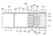
도 1에 도시된 바와 같이, 본 발명에 따르는 씨앗 발아 억제 장치(100)는 차체(110)와, 커버부(130)와, 디깅부(140)와, 마이크로파발진부(120)와, 전원부(150)와, 냉각부(160)로 이루어진다.As shown in FIG. 1, the seed
상기 차체(110)는 프레임 역할을 하는 차본체(111)와, 사람이 탑승하여 운전가능한 탑승부(113)와, 이동수단인 이동휠(115, 117)로 이루어진다. 상기 이동휠(115, 117)로는 예를 들어 바퀴이며, 캐터필러로도 구비될 수 있다.The
상기 커버부(130)는 상기 차본체(111)의 하부로 구비된다. 상기 커버부(130)는 차본체(111)에 결합되어 구비된다. 상기 커버부(130)에는 차본체(111)에 결합되어 하향 개구된 공간부(S)가 형성된다. 상기 공간부(S)는 커버부(130)의 내측으로 형성된다.The
상기 커버부(130)는 측방커버(131)와, 전방커버(135)와, 후방커버(137)로 이루어진다.The
상기 측방커버(131)는 2개이며, 전후 방향으로 연장된 판상으로 구비된다. 상기 측방커버(131)는 측방으로 이격되어 서로 마주하여 구비된다. 상기 측방커버(131)는 상부가 상기 차본체(111)에 결합되어 구비된다. The
상기 측방커버(131)의 상부에는 전후 방향으로 이격되며 상하 방향으로 길이를 가지는 복수의 장공(도시하지 않음)이 형성되어, 차본체(111)에 형성된 나사공에 볼트(138)가 체결되어 차본체(111)에 결합될 수 있다. 상기 측방커버(131)는 장공의 길이 방향을 따라 높이를 조절하여 설치하는 것이 가능하다.A plurality of long holes (not shown) spaced apart in the front-rear direction and having a length in the up-down direction are formed at the upper portion of the
도 1에 도시된 바와 같이, 상기 측방커버(131)는 하단부가 지면(G)에 삽입되는 높이로 설치된다. 상기 측방커버(131)의 하단부는 지면으로부터 1∼2㎝ 깊이(t)만큼 삽입되어 설치된다.As shown in Figure 1, the
상기 차체(110)가 도로 등에서 운행될 때 상기 측방커버(131)는 하단부의 높이를 상향 이동시켜 이동휠(115, 117)의 하부보다 상향 이격되도록 고정한다.When the
상기 전방커버(135)와 후방커버(137)는 판상으로 구비된다. 상기 전방커버(135)와 후방커버(137)는 전후방으로 이격되어 서로 마주하여 구비된다. 상기 전방커버(135)와 후방커버(137)는 상부가 상기 차본체(111)에 결합되어 구비된다. 상기 전방커버(135)와 후방커버(137)는 상부가 차본체(111)에 고정되고, 측방 양측이 측방커버(131)와 분리되어 구비된다.The
상기 후방커버(137)의 상부에는 측 방향으로 이격되며 상하 방향으로 길이를 가지는 복수의 장공(137-1)이 형성되어, 차본체(111)에 형성된 나사공(도시하지 않음)에 볼트(138)가 체결되어 차본체(111)에 결합될 수 있다. 장공(137-1)의 길이 방향을 따라 높이를 조절하여 후방커버(137)를 설치하는 것이 가능하다.A plurality of long holes 137-1 spaced apart in the lateral direction and having a length in the vertical direction are formed on the upper portion of the
상기 전방커버(135)도 후방커버(137)와 같이 장공(도시하지 않음)을 형성하여 높이를 맞추어 차본체(111)에 형성된 나사공에 볼트 체결하여 설치하는 것이 가능하다.The
상기 전방커버(135)와 후방커버(137)는 지면에 하단부가 삽입될 수 있는 높이로 설치된다.The
상기 전방커버(135)와 후방커버(137)는 차본체(111)의 하부에 후방으로 하중이 작용하면 외팔보와 같이 후방으로 변형된다. 예를 들어 차체(110)가 전진하면, 전방커버(135)와 후방커버(137)는 지면(G)에 접촉되고 돌 등에 접촉되면서 도 1에 점선으로 도시한 바와 같이 후방으로 변형된다. The
전방커버(135)와 후방커버(137)가 전진하면서 지면(G)의 씨앗이나 해충 등을 긁어 제거하는 작용도 한다.As the
상기 차체(110)가 도로 등에서 운행될 때 상기 전방커버(135)와 후방커버(137)는 하단부의 높이를 상향 이동시켜 이동휠(115, 117)의 하부보다 상향 이격되도록 고정한다.When the
상기 디깅부(140)는 상기 차본체(111)의 하부로 공간부(S)에 구비되며, 상기 전방커버(135)와 후방커버(137)로부터 전후 방향으로 이격되어 구비된다. 상기 디깅부(140)는 회전하면서 땅을 파헤치는 역할을 한다.The digging
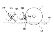
도 1 및 도 2에 도시된 바와 같이, 상기 디깅부(140)는 회전축(143)과, 디깅구동부(145)와, 디깅휠을 포함하여 이루어진다.1 and 2, the
상기 회전축(143)은 차본체(111)에 구비된다. 상기 회전축(143)은 차본체(111)로부터 하향 연장되어 측방으로 서로 이격된 2개의 브라켓(도시하지 않음)이 더 구비되어 회전축(143)의 양단이 브라켓에 회전 가능하게 구비된다. 상기 회전축(143)은 차본체(111)로부터 하향 이격되어 구비된다. 상기 회전축(143)은 상기 차본체(111)로부터의 상하 방향 이격 거리가 조정 가능하도록 구비된다. The
상기 브라켓의 상부에는 상하 방향으로 길이를 가지는 하나 이상의 장공이 형성되어, 차본체(111)에 형성된 나사공에 볼트가 체결되어 차본체(111)에 결합될 수 있다. 상기 브라켓은 장공의 길이 방향을 따라 높이를 조절하여 설치하는 것이 가능함에 다라 회전축(143)의 상하 방향 이동이 가능하게 된다.One or more long holes having a length in the vertical direction may be formed at an upper portion of the bracket, and bolts may be fastened to screw holes formed in the
상기 회전축(143)은 측방으로 연장되어 양측이 측방커버(131)에 회전 가능하게 구비될 수도 있다.The
상기 회전축(143)은 상기 이동휠(115, 117)의 회전 방향과 반대 방향으로 회전된다.The
상기 회전축(143)의 타측 단부는 디깅구동부(145)에 연결되어 회전된다. 상기 디깅구동부(145)는 차본체(111)에 구비된다.The other end of the
상기 회전축(143)에는 측방을 따라 이격되어 복수의 오목한 키홈(도시하지 않음)이 형성된다. 상기 디깅휠은 상기 키홈이 형성된 위치에 구비된다.A plurality of concave key grooves (not shown) are formed on the
상기 디깅휠은 회전축(143)에 측방향을 따라 복수로 구비된다. 상기 디깅휠은 회전축(143)에 서로 이격되어 복수로 구비된다. 상기 복수의 디깅휠은 회전축(143)이 삽입되어 일체로 회전한다. 상기 디깅휠은 상기 회전축(143)에 형성된 키홈에 키(예를 들어 반달 키, 묻힘 키 등)가 삽입됨으로써 회전축(143)과 디깅휠 사이의 상대회전이 방지된다. 상기 디깅휠은 상기 이동휠(115, 117)의 회전 방향과 반대 방향으로 회전한다.The digging wheel is provided with a plurality of
상기 디깅휠에는 회전하면서 땅을 파헤치는 복수의 디깅돌기(141)가 포함된다. 상기 디깅돌기(141)는 디깅휠의 원주 방향을 따라 복수로 구비된다. 상기 디깅돌기(141)는 디깅휠의 중심으로부터 반경 방향 외향 돌출 형성된다.The digging wheel includes a plurality of digging
상기 회전축(143)은 전후방으로 이격되어 복수로 구비될 수 있다. 상기 회전축(143)이 복수로 구비된 경우, 전후방으로 각 회전축(143)에 설치되는 디깅휠은 서로 어긋나게 구비된다.The
상기 디깅휠 회전 시, 상기 디깅돌기(141)는 지면(G)을 지면(G)으로부터 3∼5㎝ 깊이(t)로 파헤친다.When the digging wheel rotates, the digging
상기 디깅부(140)가 도 1과 같은 평지에 위치하는 경우, 상기 디깅휠의 회전 반경의 하부는 이동휠(115, 117)의 하부보다 하향 위치하어 구비된다. 상기 디깅휠은 회전하며 지면(G)에 일부가 삽입되어 지면(G)이 3∼5㎝ 깊이(t)로 파헤쳐진다.When the
도 3과 같이 지면(G)에 고랑(G1)과 이랑(G2)이 형성된 경우, 상기 이동휠(115, 117)은 고랑(G1)을 따라 이동하고, 디깅휠은 이랑(G2)을 3∼5㎝ 깊이(t1)로 파헤친다.When the furrow G1 and the furrow G2 are formed on the ground G as shown in FIG. 3, the moving
상기 디깅부(140)는 차체(110)가 도로 등에서 운행될 때 디깅부(140)가 지면(G)으로부터 멀어지도록 브라켓 또는 측방커버(131)를 상향 이동시킨 후 차체(110)를 운행한다.The
상기 마이크로파발진부(120)는 상기 차본체(111)에 구비된다. 상기 마이크로파발진부(120)는 전원부(150)와 전기적으로 연결되어 전원부(150)로부터 전력을 공급받는다. 상기 전원부(150)는 상기 차본체(111)의 상부에 구비된다.The
상기 마이크로파발진부(120)는 상기 공간부(S)로 마이크로웨이브(microwave)를 발산한다. 상기 마이크로웨이브가 발산될 때 상기 마이크로파발진부(120)에서 열이 방출되어 상기 마이크로파발진부(120)의 상부에는 마이크로파발진부(120)를 냉각시키는 냉각부(160)가 더 구비된다.The
여기서, 상기 마이크로파발진부(120)를 차체(110)에 연결하고, 마이크로발진부(120)를 제어하는 제어장치(도시하지 않음)와 전원부(150) 및 냉각부(160)는 일반적인 내용이고 본 발명의 요지가 아니므로 자세한 설명은 생략한다.Here, the control unit (not shown) for connecting the
상기 마이크로파발진부(120)는 마그네트론(121)과 도파관(123)으로 이루어진다.The
상기 마그네트론(121)은 마이크로웨이브를 발진시킨다. 상기 마이크로웨이브는 2400㎐∼2500㎐인 것이 바람직하다.The
상기 도파관(123)은 중공체인 금속관이며, 상기 마그네트론(121)의 하방으로 설치된다. 상기 도파관(123)은 하단부로 갈수록 확관되는 형태로 형성된다. 상기 도파관(123)의 단면은 원형이나 사각형과 같은 다각형으로 형성될 수 있다.The
상기 마그네트론(121)은 복수로 구비된다. 상기 복수의 마그네트론(121)의 일부는 상기 디깅부(140)의 전방에 위치하며, 다른 일부는 디깅부(140)의 상부에 위치한다.The
상기 디깅부(140)의 전방에 위치하는 마그네트론(121)은 디깅부(140)의 전방에서 전후방을 따라 배열되어 복수개 구비된다. 상기 마그네트론(121)은 측방을 따라 배열되고 전후방을 따라 배열된다.The
상기 디깅부(140) 전방에 위치하는 마그네트론(121)에 의해서 발진되는 마이크로웨이브는 디깅부(140)에 의해서 파헤쳐지기 전의 지면으로 조사되어 표면에 있는 씨앗의 발아를 억제한다("A" 영역). 상기 디깅부(140) 전방에 위치하는 마그네트론(121) 중 가장 후방의 마그네크론(121) 즉, 디깅부(140)에 가장 가깝게 설치된 마그네트론(121)에서 발진되는 마이크로웨이브는 디깅부(140)에 의하여 파헤쳐지면서 전방으로 비산되는 토양에 포함되었던 씨앗에 조사된다.The microwave oscillated by the
상기 디깅부(140)의 상부에 위치하는 마그네트론(121)은 전후방을 따라 그리고 측방으로 따라 배열되어 복수개 구비된다. 디깅부(140)의 상부에 위치하는 마그네트론(121)에서 조사되는 마이크로웨이브는 디깅부(140)에 의하여 파헤쳐지는 토양에 조사된다. 따라서 토양에 묻혀 있는 씨앗도 디깅부(140)에 의하여 파헤쳐지면서 마이크로웨이브에 의하여 발아가 억제된다("B" 영역).A plurality of
상기 마이크로파발진부(120)는 디깅부(140)의 후방에 위치하는 복수의 마그네트론(121)을 더 포함하여 구비된다.The
상기 디깅부(140) 후방에 위치하는 마그네트론(121)에 의해서 발진되는 마이크로웨이브는 디깅부(140)에 의해서 파헤쳐진 후 지면에 조사되어 파헤쳐진 지면으로 노출된 씨앗의 발아를 억제한다("C" 영역). 상기 디깅부(140) 후방에 위치하는 마그네트론(121) 중 가장 전방의 마그네크론(121) 즉, 디깅부(140)에 가장 가깝게 설치된 마그네트론(121)에서 발진되는 마이크로웨이브는 디깅부(140)에 의하여 파헤쳐지면서 후방으로 비산되는 토양에 포함되었던 씨앗에 조사된다.The microwave oscillated by the
지금까지 본 발명에 따른 씨앗 발아 억제 장치는 도면에 도시된 실시 예를 참고로 설명되었으나 이는 예시적인 것에 불과하며, 당업자라면 누구든지 이로부터 다양한 변형 및 균등한 다른 실시 예가 가능하다는 점을 이해할 것이다. 따라서, 진정한 기술적 보호범위는 첨부된 실용신안청구범위의 기술적 사상에 의하여 정해져야 할 것이다.So far the seed germination suppression apparatus according to the present invention has been described with reference to the embodiment shown in the drawings, but this is only exemplary, and any person skilled in the art will understand that various modifications and equivalent other embodiments are possible therefrom. Therefore, the true technical protection scope should be determined by the technical idea of the appended utility model claim.
100 : 씨앗 발아 억제 장치
110 : 차체
120 : 마이크로파발진부
130 : 커버부
140 : 디깅부
150 : 전원부
160 : 냉각부100: seed germination suppression device
110: body 120: microwave generator
130: cover portion 140: digging portion
150: power supply unit 160: cooling unit
Claims (7)
상기 공간부(S)에는 차본체(111)에 구비되며 회전하면서 땅을 파헤치는 디깅부(140)를 더 포함하는 것을 특징으로 하는 씨앗 발아 억제 장치.A vehicle body 110 having a moving body and made of a vehicle body 111, a cover portion 130 provided in the vehicle body 110 and forming a downwardly opened space S, and a vehicle body 111 It consists of a microwave generator 120 having a magnetron 121 for emitting microwaves to the space portion (S), and a power supply unit 150 for supplying the required power to the microwave generator 120;
The space portion (S) is provided in the vehicle body 111, the seed germination suppression device further comprises a digging portion 140 to dig the ground while rotating.
전방커버(135)와 후방커버(137)는 상부가 차본체(111)에 고정되고 측방 양측이 측방커버(131)와 분리되어 하부에 후방으로 하중이 작용하면 외팔보와 같이 후방으로 변형하는 것을 특징으로 하는 씨앗 발아 억제 장치.According to claim 1, The space portion (S) is formed inside the cover portion 130 is provided is coupled to the vehicle body 111; The cover parts 130 are spaced apart from each other and face each other, and the upper side of the plate-shaped side cover 131 coupled to the vehicle body 111, spaced apart from each other in the front and rear, and the upper part coupled to the vehicle body 111. It consists of a plate-shaped front cover 135 and rear cover 137;
The front cover 135 and the rear cover 137 are characterized in that the upper portion is fixed to the vehicle body 111, and both sides are separated from the side cover 131, so that when a load is applied to the lower portion, it deforms backward like a cantilever beam. Seed germination suppression device.
Priority Applications (1)
| Application Number | Priority Date | Filing Date | Title |
|---|---|---|---|
| KR1020180130317A KR102135127B1 (en) | 2018-10-30 | 2018-10-30 | A Apparatus For Preventing Seed From Germinating |
Applications Claiming Priority (1)
| Application Number | Priority Date | Filing Date | Title |
|---|---|---|---|
| KR1020180130317A KR102135127B1 (en) | 2018-10-30 | 2018-10-30 | A Apparatus For Preventing Seed From Germinating |
Publications (2)
| Publication Number | Publication Date |
|---|---|
| KR20200048333A true KR20200048333A (en) | 2020-05-08 |
| KR102135127B1 KR102135127B1 (en) | 2020-07-17 |
Family
ID=70678120
Family Applications (1)
| Application Number | Title | Priority Date | Filing Date |
|---|---|---|---|
| KR1020180130317A KR102135127B1 (en) | 2018-10-30 | 2018-10-30 | A Apparatus For Preventing Seed From Germinating |
Country Status (1)
| Country | Link |
|---|---|
| KR (1) | KR102135127B1 (en) |
Citations (8)
| Publication number | Priority date | Publication date | Assignee | Title |
|---|---|---|---|---|
| JP2005110516A (en) * | 2003-10-03 | 2005-04-28 | Chizaiko:Kk | Electronic weeder |
| KR20100104513A (en) | 2009-03-18 | 2010-09-29 | 전북대학교산학협력단 | An control apparatus and an control agricultural machine apparatus comprising it and control method |
| KR20120075750A (en) * | 2010-12-29 | 2012-07-09 | 이노크린 주식회사 | Environment-friendly herbicidal method and system thereof |
| KR101225931B1 (en) | 2006-02-17 | 2013-01-24 | 이영희 | Soil sterilizer |
| KR101520881B1 (en) * | 2014-11-07 | 2015-05-15 | (주)에이에이치씨시스템 | Weeds removal apparatus using a magnetron |
| KR101639941B1 (en) * | 2015-03-05 | 2016-07-25 | 장흥균 | Moving type weeds remove device using microwave |
| WO2018077360A1 (en) * | 2016-10-28 | 2018-05-03 | Weed Fighter Aps | Method and apparatus for weed control with microwaves |
| JP6403318B2 (en) * | 2014-09-16 | 2018-10-10 | みのる産業株式会社 | Paddy field weeding device |
-
2018
- 2018-10-30 KR KR1020180130317A patent/KR102135127B1/en active IP Right Grant
Patent Citations (8)
| Publication number | Priority date | Publication date | Assignee | Title |
|---|---|---|---|---|
| JP2005110516A (en) * | 2003-10-03 | 2005-04-28 | Chizaiko:Kk | Electronic weeder |
| KR101225931B1 (en) | 2006-02-17 | 2013-01-24 | 이영희 | Soil sterilizer |
| KR20100104513A (en) | 2009-03-18 | 2010-09-29 | 전북대학교산학협력단 | An control apparatus and an control agricultural machine apparatus comprising it and control method |
| KR20120075750A (en) * | 2010-12-29 | 2012-07-09 | 이노크린 주식회사 | Environment-friendly herbicidal method and system thereof |
| JP6403318B2 (en) * | 2014-09-16 | 2018-10-10 | みのる産業株式会社 | Paddy field weeding device |
| KR101520881B1 (en) * | 2014-11-07 | 2015-05-15 | (주)에이에이치씨시스템 | Weeds removal apparatus using a magnetron |
| KR101639941B1 (en) * | 2015-03-05 | 2016-07-25 | 장흥균 | Moving type weeds remove device using microwave |
| WO2018077360A1 (en) * | 2016-10-28 | 2018-05-03 | Weed Fighter Aps | Method and apparatus for weed control with microwaves |
Also Published As
| Publication number | Publication date |
|---|---|
| KR102135127B1 (en) | 2020-07-17 |
Similar Documents
| Publication | Publication Date | Title |
|---|---|---|
| US20030215354A1 (en) | Systems and methods for in situ soil sterilization, insect extermination and weed killing | |
| US6401637B1 (en) | Microwave energy applicator | |
| KR20060010733A (en) | Soil processing method | |
| US5141059A (en) | Method and apparatus for controlling agricultural pests in soil | |
| US8291843B2 (en) | Drilling apparatus and method | |
| JP6818713B2 (en) | Electromagnetic wave underground irradiation device | |
| US5862764A (en) | Method and apparatus for a floating frame field harrow | |
| KR101225931B1 (en) | Soil sterilizer | |
| US10542681B1 (en) | Steam treatment of soil | |
| US7560673B2 (en) | Device for soil sterilization, insect extermination, and weed killing using microwave energy | |
| KR102135127B1 (en) | A Apparatus For Preventing Seed From Germinating | |
| EP1183943B1 (en) | Method and apparatus for the disinfection of soil | |
| US10433494B1 (en) | Steam treatment of soil | |
| JP3588695B2 (en) | Plowing earthenware | |
| US2628546A (en) | Rod weeder | |
| Neilson et al. | Design and Field Testing of a CombinedFlaming and Cultivation Implementfor Effective Weed Control | |
| RU2352092C2 (en) | Method of meliorating soil little water-holding capacity | |
| RU2115316C1 (en) | Method of extermination of agricultural pests | |
| RU2809749C2 (en) | Soil tillage machine | |
| SU793427A1 (en) | Subsoil cultivator | |
| BR102021013578A2 (en) | SYSTEM FOR PHYSIOLOGICAL INJURY OF MICRO-ORGANISMS AND VEGETABLES WITH THE USE OF MICROWAVES | |
| Samadalashvili | The batch-combined minimum tillage farming machine | |
| Rakshith | Design & fabrication of mini tiller | |
| Monson | Controlling plant competition | |
| Reddy et al. | Efficient Use of Farm Machinery |
Legal Events
| Date | Code | Title | Description |
|---|---|---|---|
| E701 | Decision to grant or registration of patent right | ||
| GRNT | Written decision to grant |