KR20200046292A - Vehicle carrier with drainage structure - Google Patents
Vehicle carrier with drainage structure Download PDFInfo
- Publication number
- KR20200046292A KR20200046292A KR1020180127216A KR20180127216A KR20200046292A KR 20200046292 A KR20200046292 A KR 20200046292A KR 1020180127216 A KR1020180127216 A KR 1020180127216A KR 20180127216 A KR20180127216 A KR 20180127216A KR 20200046292 A KR20200046292 A KR 20200046292A
- Authority
- KR
- South Korea
- Prior art keywords
- drainage structure
- drainage
- carrier
- intake duct
- vehicle carrier
- Prior art date
- Legal status (The legal status is an assumption and is not a legal conclusion. Google has not performed a legal analysis and makes no representation as to the accuracy of the status listed.)
- Granted
Links
Images


Classifications
-
- B—PERFORMING OPERATIONS; TRANSPORTING
- B62—LAND VEHICLES FOR TRAVELLING OTHERWISE THAN ON RAILS
- B62D—MOTOR VEHICLES; TRAILERS
- B62D25/00—Superstructure or monocoque structure sub-units; Parts or details thereof not otherwise provided for
- B62D25/08—Front or rear portions
- B62D25/082—Engine compartments
- B62D25/085—Front-end modules
-
- B—PERFORMING OPERATIONS; TRANSPORTING
- B62—LAND VEHICLES FOR TRAVELLING OTHERWISE THAN ON RAILS
- B62D—MOTOR VEHICLES; TRAILERS
- B62D25/00—Superstructure or monocoque structure sub-units; Parts or details thereof not otherwise provided for
- B62D25/24—Superstructure sub-units with access or drainage openings having movable or removable closures; Sealing means therefor
Landscapes
- Engineering & Computer Science (AREA)
- Chemical & Material Sciences (AREA)
- Combustion & Propulsion (AREA)
- Transportation (AREA)
- Mechanical Engineering (AREA)
- Cooling, Air Intake And Gas Exhaust, And Fuel Tank Arrangements In Propulsion Units (AREA)
- Body Structure For Vehicles (AREA)
Abstract
본 발명은 폭우 또는 세차와 같은 환경에서도 수분이 캐리어와 흡기덕트 사이의 틈을 통해 엔진까지 유입되는 것을 방지할 수 있는 배수구조가 적용된 차량용 캐리어에 관한 것으로써, 공기를 엔진으로 보내기 위한 관통홀(110)이 형성되는 차량용 캐리어(100), 상기 관통홀(110)의 상부에서 상기 캐리어(100)의 전방을 향해 형성되어, 유입되는 물을 배출하는 배수부(200) 및 내부에 전방으로부터 유입되는 공기가 통과하는 유로가 형성되고, 후방 끝단은 상기 배수부(200)의 표면과, 상기 캐리어(100)의 전면에 결합되는 흡기덕트(300)를 포함하는 것을 특징으로 한다.The present invention relates to a vehicle carrier having a drainage structure capable of preventing moisture from entering the engine through a gap between a carrier and an intake duct even in an environment such as heavy rain or car wash, through holes for sending air to the engine ( 110 is formed for the vehicle carrier 100 is formed, the upper portion of the through-hole 110 is formed toward the front of the carrier 100, the drain 200 for discharging the incoming water and the inside flowing from the front A passage through which air passes is formed, and a rear end includes a surface of the drainage part 200 and an intake duct 300 coupled to the front surface of the carrier 100.
Description
본 발명은 배수구조가 적용된 차량용 캐리어에 관한 것이다.The present invention relates to a vehicle carrier to which a drainage structure is applied.
프론트 엔드 모듈(Front End Module, FEM)이란, 자동차의 전방에 결합되는 조립체의 총칭으로, 캐리어에 헤드램프, 공조장치, 범퍼 등의 여러 부품이 설치된 구조물을 말한다.The front end module (FEM) is a generic term for an assembly that is coupled to the front of a vehicle, and refers to a structure in which various parts such as a headlamp, an air conditioner and a bumper are installed on a carrier.
캐리어(Carrier)는 프론트 엔드 모듈의 전면부를 형성하는 일종의 골격체로, 상술한 바와 같이 다양한 구조물이 설치될 수 있으며 특히 차량의 엔진 출력을 위해 공기를 공급하는 통로 및 통로에 흡기덕트가 설치될 수 있다.The carrier is a kind of skeletal body forming the front part of the front end module, and various structures may be installed as described above, and particularly, intake ducts may be installed in passages and passages that supply air for engine output of the vehicle. .
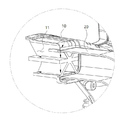
도 1은 상술한 캐리어(10)와 흡기덕트(20)가 결합된 상태를 도시한 것이고, 도 2는 도 1에서 캐리어(10)와 흡기덕트(20)가 결합된 부분을 확대 도시한 것이며, 도 3은 캐리어(10)와 흡기덕트(20)가 결합된 부분의 단면을 도시한 것이다.1 is a view showing a state in which the above-described
도 1 및 도 2에 도시된 바와 같이, 캐리어(10)의 전방에는 흡기덕트(20)가 결합되어 있으며, 흡기덕트(20)는 물 등이 흡기덕트(20)를 통해 엔진으로 공급되지 못하도록 전방 끝단이 하측으로 굴곡 형성되어 있다.1 and 2, the
일반적으로 캐리어(10)와 흡기덕트(20)는 사출하여 제작하되, 서로 별개로 제작하여 결합시키는데, 사출 변형 및 공차를 고려했을 때 캐리어(10)와 흡기덕트(20) 사이에는 일정한 틈새가 존재할 수밖에 없으며, 이러한 경우 도 3의 화살표 방향과 같이 폭우 또는 세차시 수분이 캐리어(10)와 흡기덕트(20) 사이의 틈새로 유입되어 관통홀(11)을 통해 엔진까지 유입될 수 있으며, 엔진에 수분이 유입될 경우 엔진의 출력 저하 또는 심할 경우 엔진이 멈출 수 있는 문제점이 있다.In general, the
본 발명은 상기한 바와 같은 문제점을 해결하기 위해 안출된 것으로써, 본 발명의 다양한 실시예에 의한 배수구조가 적용된 차량용 캐리어의 목적은 폭우 또는 세차와 같은 환경에서도 수분이 캐리어와 흡기덕트 사이의 틈을 통해 엔진까지 유입되는 것을 방지할 수 있는 배수구조가 적용된 차량용 캐리어를 제공함에 있다.The present invention is to solve the problems as described above, the purpose of the vehicle carrier is applied to the drainage structure according to various embodiments of the present invention, even in an environment such as heavy rain or car wash, moisture is the gap between the carrier and the intake duct It is to provide a carrier for a vehicle with a drainage structure that can be prevented from entering the engine through.
상기한 바와 같은 문제점을 해결하기 위한 본 발명에 의한 배수구조가 적용된 차량용 캐리어는, 공기를 엔진으로 보내기 위한 관통홀(110)이 형성되는 차량용 캐리어(100), 상기 관통홀(110)의 상부에서 상기 캐리어(100)의 전방을 향해 형성되어, 유입되는 물을 배출하는 배수부(200) 및 내부에 전방으로부터 유입되는 공기가 통과하는 유로가 형성되고, 후방 끝단은 상기 배수부(200)의 표면과, 상기 캐리어(100)의 전면에 결합되는 흡기덕트(300)를 포함하는 것을 특징으로 한다.The vehicle carrier to which the drainage structure according to the present invention is applied for solving the above-described problem is provided in the
또한, 상기 배수부(200)는 유입되는 물을 폭 방향으로 배출하는 것을 특징으로 한다.In addition, the
또한, 상기 배수부(200)는 상기 관통홀(110)의 상측에 형성되는 것을 특징으로 한다.In addition, the
또한, 상기 흡기덕트(300)는 후방 끝단의 상측 내면이 상기 배수부(200)의 상면과 맞닿는 것을 특징으로 한다.In addition, the
또한, 상기 배수부(200)의 폭의 길이는 상기 관통홀(110)의 폭의 길이 이상인 것을 특징으로 한다.In addition, the length of the width of the
또한, 상기 배수부(200)의 폭의 길이는 상기 흡기덕트(300)의 폭의 길이 이상인 것을 특징으로 한다.In addition, the length of the width of the
또한, 상기 흡기덕트(300)는 후방에 상기 배수부(200)의 양단이 수용되도록 함몰 형성된 삽입홀(320)을 포함하는 것을 특징으로 한다.In addition, the
또한, 상기 삽입홀(320)은 상기 흡기덕트(300)의 후방 양측 단부에 형성되는 것을 특징으로 한다.In addition, the
또한, 상기 삽입홀(320)에 형성되어 상기 흡기덕트(300) 내부로 물이 유입되는 것을 방지하는 패킹부를 더 포함하는 것을 특징으로 한다.In addition, it is characterized in that it further comprises a packing portion formed in the
또한, 상기 흡기덕트(300)는 전방 끝단이 하측으로 굴곡되는 것을 특징으로 한다.In addition, the
또한, 상기 배수부(200)는 상기 캐리어(100)의 전면에서 전방으로 연장 형성되는 제1배수구조(210) 및 상기 제1배수구조(210)의 전방 끝단에서 상측으로 연장 형성되는 제2배수구조(220)를 포함하여, 상기 캐리어(100)의 전면, 상기 제1배수구조(210) 및 상기 제2배수구조(220)로 둘러싸인 배수공간을 형성하는 것을 특징으로 한다.In addition, the
또한, 상기 배수부(200)는 상기 제2배수구조(220)의 상부 끝단에서 전방으로 연장 형성되는 제3배수구조(230)를 더 포함하는 것을 특징으로 한다.In addition, the
또한, 상기 흡기덕트(300)는 후방 끝단의 내면이 상기 제3배수구조(230)의 상면과 면접하는 것을 특징으로 한다.In addition, the
또한, 상기 흡기덕트(300)는 후방 끝단의 내면이 상기 제2배수구조(220)의 상면과 면접하는 것을 특징으로 한다.In addition, the
또한, 상기 배수공간은 폭 방향을 기준으로 일부분이 다른 부분보다 중력 방향으로 높게 형성되는 것을 특징으로 한다.In addition, the drainage space is characterized in that a portion is formed higher in the direction of gravity than the other portion based on the width direction.
상기한 바와 같은 본 발명의 다양한 실시예에 의한 배수구조가 적용된 차량용 캐리어에 의하면, 관통홀의 상부에 형성된 배수부가 제1배수구조와 제2배수구조를 통해 뒤집어진 디귿자 형상의 배수공간을 형성하므로, 차량이 폭우 또는 세차와 같은 환경에 노출되어 물이 캐리어와 흡기덕트 사이에 유입되더라도 배수공간을 통해 배수부의 외측으로 배출되어, 물이 캐리어와 흡기덕트 사이의 틈을 통해 흡기덕트 내부로 유입되는 것을 방지할 수 있는 효과가 있다.According to the vehicle carrier to which the drainage structure according to various embodiments of the present invention as described above is applied, since the drainage portion formed on the upper portion of the through hole forms a drainage space in the shape of a deflector inverted through the first drainage structure and the second drainage structure, Even though the vehicle is exposed to an environment such as heavy rain or car wash, water is discharged to the outside of the drain through the drainage space even though water flows between the carrier and the intake duct, so that water enters the intake duct through the gap between the carrier and the intake duct. It has an effect that can be prevented.
도 1은 종래의 캐리어와 흡기덕트의 결합 사시도.
도 2는 도 1의 부분 확대도.
도 3은 종래의 캐리어와 흡기덕트의 결합 단면도.
도 4는 본 발명의 제1실시예에 의한 배수구조가 적용된 차량용 캐리어의 분해 사시도.
도 5는 도 4의 부분 확대도.
도 6은 본 발명의 제1실시에에 의한 배수구조가 적용된 차량용 캐리어의 결합 단면도.
도 7은 본 발명의 제1실시예에 의한 배수구조가 적용된 차량용 캐리어의 배수부와 흡기덕트의 분해 사시도.
도 8은 본 발명의 제2실시예에 의한 배수구조가 적용된 차량용 캐리어의 결합 단면도.1 is a combined perspective view of a conventional carrier and an intake duct.
FIG. 2 is a partially enlarged view of FIG. 1.
Figure 3 is a cross-sectional view of a conventional carrier and an intake duct.
Figure 4 is an exploded perspective view of a vehicle carrier to which the drainage structure according to the first embodiment of the present invention is applied.
5 is a partially enlarged view of FIG. 4.
Figure 6 is a cross-sectional view of a vehicle carrier with a drainage structure according to the first embodiment of the present invention.
7 is an exploded perspective view of a drainage part and an intake duct of a vehicle carrier to which a drainage structure according to a first embodiment of the present invention is applied.
8 is a combined cross-sectional view of a vehicle carrier with a drainage structure according to a second embodiment of the present invention.
이하 첨부된 도면을 참고하여 본 발명에 의한 배수구조가 적용된 차량용 캐리어의 바람직한 실시예에 관하여 상세히 설명한다.Hereinafter, a preferred embodiment of a vehicle carrier to which a drainage structure according to the present invention is applied will be described in detail with reference to the accompanying drawings.
도 4는 본 발명의 제1실시예에 의한 배수구조가 적용된 차량용 캐리어를 분해한 것을 도시한 것이다.4 is an exploded view of a vehicle carrier to which a drainage structure according to a first embodiment of the present invention is applied.
도 4에 도시된 바와 같이, 본 발명의 제1실시예에 의한 배수구조가 적용된 차량용 캐리어는 캐리어(100) 및 흡기덕트(300)를 포함하며, 도 4에서 도번은 부여되지 않았으나 흡기덕트(300)가 결합되는 캐리어(100)의 전면에 형성된 배수부를 더 포함할 수 있다.As shown in FIG. 4, the vehicle carrier to which the drainage structure according to the first embodiment of the present invention is applied includes a
캐리어(100)는 앞서 발명의 배경이 되는 기술에서도 설명했듯이 프론트 엔드 모듈의 일부로, 차량의 전방에 설치되어 프론트 엔드 모듈에 포함되는 다른 구성이 결합될 수 있고, 흡기덕트(300) 또한 이러한 프론트 엔드 모듈에 포함되는 다른 구성 중 하나이다.The
도 5는 도 4의 일부분을 확대 도시한 것이다.FIG. 5 is an enlarged view of a portion of FIG. 4.
도 5에 도시된 바와 같이, 캐리어(100)의 외곽 전면에는 관통홀(110)이 형성될 수 있다.As shown in FIG. 5, a
관통홀(110) 또한 캐리어(100)와 마찬가지로 발명의 배경이 되는 기술에서 설명한 것으로, 차량 전방의 그릴로부터 유입되는 공기 중 일부를 엔진까지 보내기 위해 형성된다.The through-
엔진(미도시)과 관통홀(110) 사이에는 별도의 파이프 또는 덕트와 같이 유로를 형성하는 부재가 설치되고, 해당 부재는 관통홀(110)에서 유입되는 공기가 엔진으로 이동하는 일종의 통로가 될 수 있으며, 도 5에 도시된 바와 같이 관통홀(110) 내부에는 별도의 프레임 구조(111)가 적용되어 관통홀(110)이 형성됨으로써 발생할 수 있는 캐리어(100)의 내구성 저하를 방지할 수 있다.Between the engine (not shown) and the through-
도 5에 도시된 바와 같이, 배수부(200)는 공기가 유입되는 관통홀(110)의 상부에 형성되는 구조체로, 후술할 흡기덕트(300)와 결합된다. 배수부(200)의 상세한 구성에 대해서는 후술한다.As shown in FIG. 5, the
도 4에 도시된 바와 같이, 흡기덕트(300)는 내부에 유로가 형성되고, 전단이 하측으로 굴곡되어 있으며, 후단이 상술한 배수부(200) 및 캐리어(100)의 전면과 결합된다. 흡기덕트(300)의 전단이 하측으로 굴곡되는 이유는 흡기덕트(300)의 전단을 통해 유입되는 공기에 수분이 포함될 경우, 수분이 엔진의 성능을 저하시킬 수 있기 때문에 수분이 흡기덕트(300) 내부로 유입되어 엔진으로 전달되는 것을 방지하기 위해서이다.As shown in Figure 4, the
도 4에 도시된 바와 같이, 흡기덕트(300)는 외부에 캐리어(100)와의 결합을 위한 결합부재(310)를 더 포함할 수 있다. 도 4에서 결합부재(310)는 일종의 브라켓으로 나사를 통해 흡기덕트(300)와 캐리어(100)를 결합시키지만, 본 발명은 이에 한정하지 않으며 다양한 결합방법을 사용하여 캐리어(100)와 흡기덕트(300)를 결합시킬 수 있으며, 결합부재의 다른 예로써 끼움구조를 통해 흡기덕트(300)와 캐리어(100)가 결합될 수 있다.As illustrated in FIG. 4, the
도 6은 본 발명의 제1실시예에 의한 배수구조가 적용된 차량용 캐리어에서 캐리어(100)에 형성된 배수부(200)에 흡기덕트(300)가 결합된 단면을 도시한 것이다.6 is a cross-sectional view showing the
도 6에 도시된 바와 같이, 배수부(200)는 제1배수구조(210), 제2배수구조(220) 및 제3배수구조(230)를 포함할 수 있다.6, the
도 6에 도시된 바와 같이, 제1배수구조(210)는 관통홀(110)의 상부에서 전방을 향해 돌출 형성되며, 전방에 수직한 방향으로 캐리어(100)의 전면을 따라 연장된다.As illustrated in FIG. 6, the
도 6에 도시된 바와 같이, 제2배수구조(220)는 제1배수구조(210)의 전방 끝단에서 상측으로 연장 형성된 부재이다. 배수부(200)는 제1배수구조(210) 및 제2배수구조(220)를 포함함으로써, 캐리어(100)의 전면, 제1배수구조(210) 및 제2배수구조(220)로 둘러싼 일종의 배수공간을 형성하는데, 외부에서 물이 유입되어 캐리어(100)와 흡기덕트(300) 사이의 틈으로 흘러들어오더라도 배수공간이 흘러들어온 물이 관통홀(110)로 유입되는 것을 차단하고 외측(전방에 수직한 배수부(200)의 폭 방향 양측)으로 물이 흐르도록 유도한다.As illustrated in FIG. 6, the
도 6에 도시된 바와 같이, 제3배수구조(230)는 제2배수구조(220)의 상단에서 전방을 향해 돌출되는 부분이다. 본 발명의 제1실시예에 의한 배수구조가 적용된 차량용 캐리어에서 제3배수구조(230)는 흡기덕트(300)와의 결합력을 높이기 위한 부분으로, 제3배수구조(230)의 상면과 흡기덕트(300)의 후방의 상단 내면이 서로 면접함으로써, 배수부(200)에 흡기덕트(300)가 안정적으로 결합될 수 있도록 한다.As illustrated in FIG. 6, the
도 7은 캐리어(100)를 생략하고, 배수부(200)와 흡기덕트(300)가 서로 분리된 상태를 도시한 것이다.7 illustrates a state in which the
도 7에 도시된 바와 같이, 흡기덕트(300)는 배수부(200)와 결합되는 후단 외측에 삽입홀(320)이 형성될 수 있다.As illustrated in FIG. 7, the
배수부(200)는 구조적으로 폭 방향 양단이 외측이 흡기덕트(300)의 외측으로 빠져나와야만, 배수부(200)의 폭 방향으로 배출되는 물이 흡기덕트(300)의 내부로 유입되는 것을 방지할 수 있다. 따라서 배수부(200)의 폭 방향 길이는 도 7에 도시된 바와 같이 흡기덕트(300)의 폭, 즉 흡기덕트(300)의 후방 양측 단부 사이의 거리 이상이어야 하며, 결합홀(110)의 폭 방향 길이 이상이어야만 하며, 이렇듯 배수부(200)의 폭 방향 길이가 결합홀(110) 및 흡기덕트(300)의 폭 방향 길이 이상이기 때문에, 흡기덕트(300)의 후방에는 결합홀(320)이 형성된다.
도 7에 도시된 바와 같이, 결합홀(320)은 배수부(200)의 형상에 대응되는 형상일 수 있으며, 도면에는 도시되지 않았지만, 결합홀(320)과 배수부(200) 사이로 물이 유입되어 흡기덕트(300) 내부로 물이 유입되는 것을 방지하기 위해 결합홀(320)과 배수부(200) 사이에는 탄성을 가지는 패킹부재가 형성될 수 있다.As shown in FIG. 7, the
상술한 본 발명의 제1실시예에서 배수부(200)가 제1 내지 제3배수구조(210, 220, 230)를 포함하는 것과 달리, 제3배수구조(230)가 없는 실시예가 있을 수 있다.Unlike in the first embodiment of the present invention, the
도 8은 본 발명의 제2실시예에 의한 배수구조가 적용된 차량용 캐리어의 결합된 상태의 단면을 도시한 것이다.8 is a cross-sectional view showing a combined state of a vehicle carrier to which a drainage structure according to a second embodiment of the present invention is applied.
도 8에 도시된 바와 같이, 본 발명의 제2실시예에 의한 배수구조가 적용된 차량용 캐리어에서 배수부(200)는 제1실시예와 달리 제3배수구조가 없고, 제1 및 제2배수구조(210, 220)만을 포함하되, 제2배수구조(220)의 전후방향으로 연장된 길이가 제1실시예보다 길다. 즉, 본 발명의 제2실시예에 의한 배수구조가 적용된 차량용 캐리어는 제2배수구조(220)가 전후방향으로 길게 형성됨으로써, 제3배수구조의 역할을 해, 흡기덕트(300)가 보다 안정적으로 캐리어(100)에 형성된 배수부(200)에 결합될 수 있도록 한다.As shown in FIG. 8, in the vehicle carrier to which the drainage structure according to the second embodiment of the present invention is applied, the
앞서 도면에서 도시된 배수부(200)는 캐리어(100)의 전방에 폭 방향으로 연장 형성됨으로써, 배수부(200)가 형성하는 배수공간은 폭 방향으로 평평한 형상이 된다. 단, 본 발명은 배수공간의 경사가 상술한 바와 같이 평평한 형상이 되는 것에 한정하지는 않으며, 폭 방향을 기준으로 일부분이 다른 부분보다 중력방향을 기준으로 했을 때 높을 수 있다. 즉, 보다 상세히 배수부(200)에 포함되는 제1배수구조(210)가 평평하지 않고 경사를 가질 수 있다.The
제1배수구조(210)에서 다른 부분보다 높은 부분은, 중단 또는 일측 끝단일 수 있으며, 이를 통해 제1배수구조(210), 제2배수구조(220) 및 캐리어(100)의 전면이 형성하는 배수공간으로 유입되는 물은 낮은 부분으로 보다 용이하게 배출될 수 있다.The portion higher than the other portion in the
본 발명은 상술한 바와 같은 구조를 가짐으로써, 캐리어(100)와 흡기덕트(300) 사이로 물이 흘러들어오는 것을 방지할 수 있는 효과가 있다. 단, 본 발명은 상술한 실시예에 본 발명의 구성들을 한정하는 것이 아니며, 제2배수구조(220) 또는 제3배수구조(230)와 흡기덕트(300)의 내면 사이에 패킹부재가 형성되어 흡기덕트(300) 내부로 물이 유입되는 것을 더욱 차단할 수 있으며, 이와는 별개로 제1배수구조(210)가 캐리어(100)의 전면을 따라 평행하게 연장되지 않고, 양단 중 일측이 하측에 위치하도록 경사가 지도록 형성되거나, 중단이 양단보다 높게 형성되어, 배수부(200)가 형성하는 배수공간으로 유입된 물을 보다 용이하게 외측으로 배출시키는 실시예가 있을 수 있다.The present invention has the structure as described above, it is effective to prevent water from flowing between the
본 발명은 상기한 실시예에 한정되지 아니하며, 적용범위가 다양함은 물론이고, 청구범위에서 청구하는 본 발명의 요지를 벗어남이 없이 다양한 변형 실시가 가능한 것은 물론이다.The present invention is not limited to the above-described embodiments, and the scope of application is various, of course, and various modifications can be implemented without departing from the gist of the present invention as claimed in the claims.
10, 100 : 캐리어
11, 110 : 관통홀
20, 300 : 흡기덕트
200 : 배수부
210 : 제1배수구조
220 : 제2배수구조
230 : 제3배수구조
310 : 결합부재
320 : 삽입홀10, 100: carrier
11, 110: Through hole
20, 300: Intake duct
200: drainage part
210: first drainage structure
220: second drainage structure
230: third drainage structure
310: coupling member
320: insertion hole
Claims (15)
상기 관통홀(110)의 상부에서 상기 캐리어(100)의 전방을 향해 형성되어, 유입되는 물을 배출하는 배수부(200); 및
내부에 전방으로부터 유입되는 공기가 통과하는 유로가 형성되고, 후방 끝단은 상기 배수부(200)의 표면과, 상기 캐리어(100)의 전면에 결합되는 흡기덕트(300);
를 포함하는 것을 특징으로 하는 배수구조가 적용된 차량용 캐리어.
A vehicle carrier 100 in which a through hole 110 for sending air to the engine is formed;
It is formed toward the front of the carrier 100 from the upper portion of the through-hole 110, a drain 200 for discharging the incoming water; And
A flow path through which air introduced from the front passes is formed inside, and the rear end has an intake duct 300 coupled to the surface of the drainage part 200 and the front surface of the carrier 100;
Vehicle carrier is applied to the drainage structure, characterized in that it comprises a.
상기 배수부(200)는 유입되는 물을 폭 방향으로 배출하는 것을 특징으로 하는 배수구조가 적용된 차량용 캐리어.
According to claim 1,
The drainage unit 200 is a vehicle carrier with a drainage structure, characterized in that for discharging the incoming water in the width direction.
상기 배수부(200)는 상기 관통홀(110)의 상측에 형성되는 것을 특징으로 하는 배수구조가 적용된 차량용 캐리어.
According to claim 1,
The drainage unit 200 is a vehicle carrier with a drainage structure, characterized in that formed on the upper side of the through-hole (110).
상기 흡기덕트(300)는 후방 끝단의 상측 내면이 상기 배수부(200)의 상면과 맞닿는 것을 특징으로 하는 배수구조가 적용된 차량용 캐리어.
According to claim 3,
The intake duct 300 is a vehicle carrier with a drainage structure, characterized in that the upper inner surface of the rear end abuts the upper surface of the drainage part 200.
상기 배수부(200)의 폭의 길이는 상기 관통홀(110)의 폭의 길이 이상인 것을 특징으로 하는 배수구조가 적용된 차량용 캐리어.
According to claim 3,
The length of the width of the drain 200 is a vehicle carrier with a drainage structure, characterized in that the length of the width of the through-hole 110 or more.
상기 배수부(200)의 폭의 길이는 상기 흡기덕트(300)의 폭의 길이 이상인 것을 특징으로 하는 배수구조가 적용된 차량용 캐리어.
The method of claim 5,
The length of the width of the drain 200 is a vehicle carrier with a drainage structure, characterized in that the length of the intake duct 300 or more.
상기 흡기덕트(300)는 후방에 상기 배수부(200)의 양단이 수용되도록 함몰 형성된 삽입홀(320)을 포함하는 것을 특징으로 하는 배수구조가 적용된 차량용 캐리어.
The method of claim 6,
The intake duct 300 is a vehicle carrier with a drainage structure, characterized in that it includes an insertion hole 320 that is recessed so that both ends of the drainage portion 200 are accommodated in the rear.
상기 삽입홀(320)은 상기 흡기덕트(300)의 후방 양측 단부에 형성되는 것을 특징으로 하는 배수구조가 적용된 차량용 캐리어.
The method of claim 7,
The insertion hole 320 is a vehicle carrier with a drainage structure, characterized in that formed on both rear ends of the intake duct (300).
상기 삽입홀(320)에 형성되어 상기 흡기덕트(300) 내부로 물이 유입되는 것을 방지하는 패킹부를 더 포함하는 것을 특징으로 하는 배수구조가 적용된 차량용 캐리어.
The method of claim 7,
A vehicle carrier having a drainage structure, characterized in that it further includes a packing part formed in the insertion hole 320 to prevent water from entering the intake duct 300.
상기 흡기덕트(300)는 전방 끝단이 하측으로 굴곡되는 것을 특징으로 하는 배수구조가 적용된 차량용 캐리어.
According to claim 1,
The intake duct 300 is a vehicle carrier with a drainage structure characterized in that the front end is bent downward.
상기 배수부(200)는
상기 캐리어(100)의 전면에서 전방으로 연장 형성되는 제1배수구조(210) 및 상기 제1배수구조(210)의 전방 끝단에서 상측으로 연장 형성되는 제2배수구조(220)를 포함하여, 상기 캐리어(100)의 전면, 상기 제1배수구조(210) 및 상기 제2배수구조(220)로 둘러싸인 배수공간을 형성하는 것을 특징으로 하는 배수구조가 적용된 차량용 캐리어.
According to claim 1,
The drain 200 is
Including a first drainage structure 210 extending forward from the front of the carrier 100 and a second drainage structure 220 extending upward from the front end of the first drainage structure 210, the A vehicle carrier having a drainage structure applied to the front surface of the carrier 100, characterized by forming a drainage space surrounded by the first drainage structure 210 and the second drainage structure 220.
상기 배수부(200)는 상기 제2배수구조(220)의 상부 끝단에서 전방으로 연장 형성되는 제3배수구조(230)를 더 포함하는 것을 특징으로 하는 배수구조가 적용된 차량용 캐리어.
The method of claim 11,
The drainage part 200 further includes a third drainage structure 230 that extends forward from the upper end of the second drainage structure 220.
상기 흡기덕트(300)는 후방 끝단의 내면이 상기 제3배수구조(230)의 상면과 면접하는 것을 특징으로 하는 배수구조가 적용된 차량용 캐리어.
The method of claim 12,
The intake duct 300 is a vehicle carrier with a drainage structure, characterized in that the inner surface of the rear end is in contact with the upper surface of the third drainage structure 230.
상기 흡기덕트(300)는 후방 끝단의 내면이 상기 제2배수구조(220)의 상면과 면접하는 것을 특징으로 하는 배수구조가 적용된 차량용 캐리어.
The method of claim 11,
The intake duct 300 is a vehicle carrier with a drainage structure, characterized in that the inner surface of the rear end is in contact with the upper surface of the second drainage structure (220).
상기 배수공간은 폭 방향을 기준으로 일부분이 다른 부분보다 중력 방향으로 높게 형성되는 것을 특징으로 하는 배수구조가 적용된 차량용 캐리어.
The method of claim 11,
The drainage space is a carrier for a vehicle with a drainage structure, characterized in that a part of the drainage structure is formed higher than the other part based on the width direction.
Priority Applications (1)
| Application Number | Priority Date | Filing Date | Title |
|---|---|---|---|
| KR1020180127216A KR102533353B1 (en) | 2018-10-24 | 2018-10-24 | Vehicle carrier with drainage structure |
Applications Claiming Priority (1)
| Application Number | Priority Date | Filing Date | Title |
|---|---|---|---|
| KR1020180127216A KR102533353B1 (en) | 2018-10-24 | 2018-10-24 | Vehicle carrier with drainage structure |
Publications (2)
| Publication Number | Publication Date |
|---|---|
| KR20200046292A true KR20200046292A (en) | 2020-05-07 |
| KR102533353B1 KR102533353B1 (en) | 2023-05-19 |
Family
ID=70733598
Family Applications (1)
| Application Number | Title | Priority Date | Filing Date |
|---|---|---|---|
| KR1020180127216A Active KR102533353B1 (en) | 2018-10-24 | 2018-10-24 | Vehicle carrier with drainage structure |
Country Status (1)
| Country | Link |
|---|---|
| KR (1) | KR102533353B1 (en) |
Cited By (1)
| Publication number | Priority date | Publication date | Assignee | Title |
|---|---|---|---|---|
| KR20230050598A (en) * | 2021-10-08 | 2023-04-17 | 한온시스템 주식회사 | Air-guard having sub-guide structure |
Citations (5)
| Publication number | Priority date | Publication date | Assignee | Title |
|---|---|---|---|---|
| JPS6011444B2 (en) * | 1979-01-31 | 1985-03-26 | 松下電器産業株式会社 | Organic temperature sensor composition |
| KR20080040529A (en) | 2006-11-03 | 2008-05-08 | 한라공조주식회사 | Carrier of the front end module |
| JP4684088B2 (en) * | 2005-11-28 | 2011-05-18 | 日本プラスト株式会社 | Cowl top cover seal structure |
| KR20140120761A (en) * | 2013-04-04 | 2014-10-14 | 현대모비스 주식회사 | Duel duct carrier |
| KR20160120947A (en) * | 2015-04-09 | 2016-10-19 | 한온시스템 주식회사 | Active air flap |
Family Cites Families (1)
| Publication number | Priority date | Publication date | Assignee | Title |
|---|---|---|---|---|
| JP6011444B2 (en) * | 2013-05-07 | 2016-10-19 | スズキ株式会社 | Vehicle front structure |
-
2018
- 2018-10-24 KR KR1020180127216A patent/KR102533353B1/en active Active
Patent Citations (5)
| Publication number | Priority date | Publication date | Assignee | Title |
|---|---|---|---|---|
| JPS6011444B2 (en) * | 1979-01-31 | 1985-03-26 | 松下電器産業株式会社 | Organic temperature sensor composition |
| JP4684088B2 (en) * | 2005-11-28 | 2011-05-18 | 日本プラスト株式会社 | Cowl top cover seal structure |
| KR20080040529A (en) | 2006-11-03 | 2008-05-08 | 한라공조주식회사 | Carrier of the front end module |
| KR20140120761A (en) * | 2013-04-04 | 2014-10-14 | 현대모비스 주식회사 | Duel duct carrier |
| KR20160120947A (en) * | 2015-04-09 | 2016-10-19 | 한온시스템 주식회사 | Active air flap |
Cited By (1)
| Publication number | Priority date | Publication date | Assignee | Title |
|---|---|---|---|---|
| KR20230050598A (en) * | 2021-10-08 | 2023-04-17 | 한온시스템 주식회사 | Air-guard having sub-guide structure |
Also Published As
| Publication number | Publication date |
|---|---|
| KR102533353B1 (en) | 2023-05-19 |
Similar Documents
| Publication | Publication Date | Title |
|---|---|---|
| JP5227063B2 (en) | Intake duct for vehicle | |
| US8474558B2 (en) | Engine intake passage structure of front vehicle body | |
| US10059291B2 (en) | Vehicle lower structure | |
| US8702157B2 (en) | Vehicle front structure | |
| US20120049547A1 (en) | Front structure of vehicle | |
| JP2006264506A (en) | Mounting structure of heat exchanger for vehicle | |
| JP5474151B2 (en) | Intake duct for vehicle | |
| KR20200046292A (en) | Vehicle carrier with drainage structure | |
| CN204511639U (en) | A kind of suction means of mobile engine | |
| RU2582522C2 (en) | Air blowing device for vehicle front part | |
| JP5297093B2 (en) | Vehicle lamp | |
| CN100503341C (en) | Vehicle Drainage Structure | |
| JP6699578B2 (en) | Vehicle front structure | |
| JP2005120920A (en) | Intake duct of internal combustion engine and vehicle equipped with the intake duct | |
| JP5263671B2 (en) | Intake device for vehicle engine | |
| FR3125790A1 (en) | SHOCK ABSORPTION AND AIR DEFLECTION DEVICE FOR A VEHICLE | |
| JP7063676B2 (en) | Vehicle spoiler | |
| JPWO2006040814A1 (en) | truck | |
| JP2015027818A (en) | Cooling structure of lower side region of engine | |
| JP2006176070A (en) | Cowl louver | |
| KR102249595B1 (en) | Air cleaner unit for vehicles | |
| KR102156892B1 (en) | real wheel deflector installation structure for vehicle | |
| KR101545680B1 (en) | Carrier in the front-end module | |
| JP2009208546A (en) | Front part structure for automobile | |
| JP4854476B2 (en) | Vehicle intake duct |
Legal Events
| Date | Code | Title | Description |
|---|---|---|---|
| PA0109 | Patent application |
St.27 status event code: A-0-1-A10-A12-nap-PA0109 |
|
| PG1501 | Laying open of application |
St.27 status event code: A-1-1-Q10-Q12-nap-PG1501 |
|
| A201 | Request for examination | ||
| PA0201 | Request for examination |
St.27 status event code: A-1-2-D10-D11-exm-PA0201 |
|
| D13-X000 | Search requested |
St.27 status event code: A-1-2-D10-D13-srh-X000 |
|
| D14-X000 | Search report completed |
St.27 status event code: A-1-2-D10-D14-srh-X000 |
|
| E902 | Notification of reason for refusal | ||
| PE0902 | Notice of grounds for rejection |
St.27 status event code: A-1-2-D10-D21-exm-PE0902 |
|
| E13-X000 | Pre-grant limitation requested |
St.27 status event code: A-2-3-E10-E13-lim-X000 |
|
| P11-X000 | Amendment of application requested |
St.27 status event code: A-2-2-P10-P11-nap-X000 |
|
| P13-X000 | Application amended |
St.27 status event code: A-2-2-P10-P13-nap-X000 |
|
| E701 | Decision to grant or registration of patent right | ||
| PE0701 | Decision of registration |
St.27 status event code: A-1-2-D10-D22-exm-PE0701 |
|
| PR0701 | Registration of establishment |
St.27 status event code: A-2-4-F10-F11-exm-PR0701 |
|
| PR1002 | Payment of registration fee |
St.27 status event code: A-2-2-U10-U11-oth-PR1002 Fee payment year number: 1 |
|
| PG1601 | Publication of registration |
St.27 status event code: A-4-4-Q10-Q13-nap-PG1601 |
|
| PN2301 | Change of applicant |
St.27 status event code: A-5-5-R10-R13-asn-PN2301 St.27 status event code: A-5-5-R10-R11-asn-PN2301 |
|
| R11 | Change to the name of applicant or owner or transfer of ownership requested |
Free format text: ST27 STATUS EVENT CODE: A-5-5-R10-R11-ASN-PN2301 (AS PROVIDED BY THE NATIONAL OFFICE) |
|
| R13 | Change to the name of applicant or owner recorded |
Free format text: ST27 STATUS EVENT CODE: A-5-5-R10-R13-ASN-PN2301 (AS PROVIDED BY THE NATIONAL OFFICE) |