KR20200046030A - Intraoral sensor and method for manufacturing intraoral sensor - Google Patents
Intraoral sensor and method for manufacturing intraoral sensor Download PDFInfo
- Publication number
- KR20200046030A KR20200046030A KR1020207005389A KR20207005389A KR20200046030A KR 20200046030 A KR20200046030 A KR 20200046030A KR 1020207005389 A KR1020207005389 A KR 1020207005389A KR 20207005389 A KR20207005389 A KR 20207005389A KR 20200046030 A KR20200046030 A KR 20200046030A
- Authority
- KR
- South Korea
- Prior art keywords
- main surface
- scintillator
- edge
- image sensor
- fop
- Prior art date
Links
- 238000004519 manufacturing process Methods 0.000 title claims description 23
- 238000000034 method Methods 0.000 title claims description 17
- 230000003287 optical effect Effects 0.000 claims description 34
- 239000000835 fiber Substances 0.000 claims description 32
- 239000000463 material Substances 0.000 claims description 30
- 238000001514 detection method Methods 0.000 claims description 19
- 239000013307 optical fiber Substances 0.000 claims description 6
- 238000000151 deposition Methods 0.000 claims 1
- 230000001747 exhibiting effect Effects 0.000 claims 1
- 239000000758 substrate Substances 0.000 description 27
- XQPRBTXUXXVTKB-UHFFFAOYSA-M caesium iodide Chemical compound [I-].[Cs+] XQPRBTXUXXVTKB-UHFFFAOYSA-M 0.000 description 11
- 239000013078 crystal Substances 0.000 description 7
- 230000005855 radiation Effects 0.000 description 6
- 210000000214 mouth Anatomy 0.000 description 4
- 238000007740 vapor deposition Methods 0.000 description 4
- 230000001629 suppression Effects 0.000 description 3
- 235000010678 Paulownia tomentosa Nutrition 0.000 description 2
- 240000002834 Paulownia tomentosa Species 0.000 description 2
- 230000015572 biosynthetic process Effects 0.000 description 2
- 238000012986 modification Methods 0.000 description 2
- 230000004048 modification Effects 0.000 description 2
- WFKWXMTUELFFGS-UHFFFAOYSA-N tungsten Chemical compound [W] WFKWXMTUELFFGS-UHFFFAOYSA-N 0.000 description 2
- 229910052721 tungsten Inorganic materials 0.000 description 2
- 239000010937 tungsten Substances 0.000 description 2
- 229920000122 acrylonitrile butadiene styrene Polymers 0.000 description 1
- 230000007423 decrease Effects 0.000 description 1
- 230000000694 effects Effects 0.000 description 1
- 239000011521 glass Substances 0.000 description 1
- 229920002379 silicone rubber Polymers 0.000 description 1
- 239000004945 silicone rubber Substances 0.000 description 1
Images


Classifications
-
- A—HUMAN NECESSITIES
- A61—MEDICAL OR VETERINARY SCIENCE; HYGIENE
- A61B—DIAGNOSIS; SURGERY; IDENTIFICATION
- A61B6/00—Apparatus or devices for radiation diagnosis; Apparatus or devices for radiation diagnosis combined with radiation therapy equipment
- A61B6/50—Apparatus or devices for radiation diagnosis; Apparatus or devices for radiation diagnosis combined with radiation therapy equipment specially adapted for specific body parts; specially adapted for specific clinical applications
- A61B6/51—Apparatus or devices for radiation diagnosis; Apparatus or devices for radiation diagnosis combined with radiation therapy equipment specially adapted for specific body parts; specially adapted for specific clinical applications for dentistry
- A61B6/512—Intraoral means
-
- G—PHYSICS
- G01—MEASURING; TESTING
- G01T—MEASUREMENT OF NUCLEAR OR X-RADIATION
- G01T1/00—Measuring X-radiation, gamma radiation, corpuscular radiation, or cosmic radiation
- G01T1/16—Measuring radiation intensity
- G01T1/20—Measuring radiation intensity with scintillation detectors
- G01T1/2018—Scintillation-photodiode combinations
- G01T1/20185—Coupling means between the photodiode and the scintillator, e.g. optical couplings using adhesives with wavelength-shifting fibres
-
- A61B6/145—
-
- A—HUMAN NECESSITIES
- A61—MEDICAL OR VETERINARY SCIENCE; HYGIENE
- A61B—DIAGNOSIS; SURGERY; IDENTIFICATION
- A61B1/00—Instruments for performing medical examinations of the interior of cavities or tubes of the body by visual or photographical inspection, e.g. endoscopes; Illuminating arrangements therefor
- A61B1/24—Instruments for performing medical examinations of the interior of cavities or tubes of the body by visual or photographical inspection, e.g. endoscopes; Illuminating arrangements therefor for the mouth, i.e. stomatoscopes, e.g. with tongue depressors; Instruments for opening or keeping open the mouth
-
- A—HUMAN NECESSITIES
- A61—MEDICAL OR VETERINARY SCIENCE; HYGIENE
- A61B—DIAGNOSIS; SURGERY; IDENTIFICATION
- A61B5/00—Measuring for diagnostic purposes; Identification of persons
- A61B5/0059—Measuring for diagnostic purposes; Identification of persons using light, e.g. diagnosis by transillumination, diascopy, fluorescence
- A61B5/0082—Measuring for diagnostic purposes; Identification of persons using light, e.g. diagnosis by transillumination, diascopy, fluorescence adapted for particular medical purposes
- A61B5/0088—Measuring for diagnostic purposes; Identification of persons using light, e.g. diagnosis by transillumination, diascopy, fluorescence adapted for particular medical purposes for oral or dental tissue
-
- A—HUMAN NECESSITIES
- A61—MEDICAL OR VETERINARY SCIENCE; HYGIENE
- A61B—DIAGNOSIS; SURGERY; IDENTIFICATION
- A61B6/00—Apparatus or devices for radiation diagnosis; Apparatus or devices for radiation diagnosis combined with radiation therapy equipment
- A61B6/10—Safety means specially adapted therefor
- A61B6/102—Protection against mechanical damage, e.g. anti-collision devices
-
- A—HUMAN NECESSITIES
- A61—MEDICAL OR VETERINARY SCIENCE; HYGIENE
- A61B—DIAGNOSIS; SURGERY; IDENTIFICATION
- A61B6/00—Apparatus or devices for radiation diagnosis; Apparatus or devices for radiation diagnosis combined with radiation therapy equipment
- A61B6/42—Arrangements for detecting radiation specially adapted for radiation diagnosis
- A61B6/4208—Arrangements for detecting radiation specially adapted for radiation diagnosis characterised by using a particular type of detector
- A61B6/425—Arrangements for detecting radiation specially adapted for radiation diagnosis characterised by using a particular type of detector using detectors specially adapted to be used in the interior of the body
-
- G—PHYSICS
- G01—MEASURING; TESTING
- G01T—MEASUREMENT OF NUCLEAR OR X-RADIATION
- G01T1/00—Measuring X-radiation, gamma radiation, corpuscular radiation, or cosmic radiation
- G01T1/16—Measuring radiation intensity
- G01T1/161—Applications in the field of nuclear medicine, e.g. in vivo counting
-
- G—PHYSICS
- G01—MEASURING; TESTING
- G01T—MEASUREMENT OF NUCLEAR OR X-RADIATION
- G01T1/00—Measuring X-radiation, gamma radiation, corpuscular radiation, or cosmic radiation
- G01T1/16—Measuring radiation intensity
- G01T1/20—Measuring radiation intensity with scintillation detectors
-
- G—PHYSICS
- G01—MEASURING; TESTING
- G01T—MEASUREMENT OF NUCLEAR OR X-RADIATION
- G01T1/00—Measuring X-radiation, gamma radiation, corpuscular radiation, or cosmic radiation
- G01T1/16—Measuring radiation intensity
- G01T1/20—Measuring radiation intensity with scintillation detectors
- G01T1/2002—Optical details, e.g. reflecting or diffusing layers
-
- A—HUMAN NECESSITIES
- A61—MEDICAL OR VETERINARY SCIENCE; HYGIENE
- A61B—DIAGNOSIS; SURGERY; IDENTIFICATION
- A61B2562/00—Details of sensors; Constructional details of sensor housings or probes; Accessories for sensors
- A61B2562/12—Manufacturing methods specially adapted for producing sensors for in-vivo measurements
-
- A—HUMAN NECESSITIES
- A61—MEDICAL OR VETERINARY SCIENCE; HYGIENE
- A61B—DIAGNOSIS; SURGERY; IDENTIFICATION
- A61B2562/00—Details of sensors; Constructional details of sensor housings or probes; Accessories for sensors
- A61B2562/22—Arrangements of medical sensors with cables or leads; Connectors or couplings specifically adapted for medical sensors
- A61B2562/225—Connectors or couplings
Landscapes
- Health & Medical Sciences (AREA)
- Life Sciences & Earth Sciences (AREA)
- Physics & Mathematics (AREA)
- Medical Informatics (AREA)
- Engineering & Computer Science (AREA)
- Molecular Biology (AREA)
- High Energy & Nuclear Physics (AREA)
- Surgery (AREA)
- General Health & Medical Sciences (AREA)
- Biomedical Technology (AREA)
- Nuclear Medicine, Radiotherapy & Molecular Imaging (AREA)
- Optics & Photonics (AREA)
- Pathology (AREA)
- Veterinary Medicine (AREA)
- Biophysics (AREA)
- Public Health (AREA)
- Animal Behavior & Ethology (AREA)
- Heart & Thoracic Surgery (AREA)
- Radiology & Medical Imaging (AREA)
- Dentistry (AREA)
- Oral & Maxillofacial Surgery (AREA)
- Spectroscopy & Molecular Physics (AREA)
- General Physics & Mathematics (AREA)
- Audiology, Speech & Language Pathology (AREA)
- Measurement Of Radiation (AREA)
- Apparatus For Radiation Diagnosis (AREA)
- Endoscopes (AREA)
Abstract
구강 내 센서는, 이미지 센서와, FOP와, 신틸레이터와, 케이스를 구비하고 있다. FOP는, 제1 주면과, 제2 주면과, 복수의 측면을 가지고 있다. 제1 주면 및 제2 주면은, 다각 형상을 나타내고 있다. 제2 주면의 가장자리는, 복수의 모서리부와, 서로 이웃하는 모서리부를 연결하고 있는 복수의 변부로 구성되어 있다. 신틸레이터는, 각 모서리부와, 서로 이웃하는 측면으로 구성되는 각 능부가 노출되도록, 제2 주면과 복수의 측면에 마련되어 있다. The intraoral sensor has an image sensor, an FOP, a scintillator, and a case. The FOP has a first main surface, a second main surface, and a plurality of side surfaces. The first main surface and the second main surface have a polygonal shape. The edge of the second main surface is composed of a plurality of edge portions and a plurality of edge portions connecting the edge portions adjacent to each other. The scintillator is provided on the second main surface and the plurality of side surfaces such that each corner portion and each twill portion composed of adjacent side surfaces are exposed.

Description
본 발명은, 구강 내 센서, 및 구강 내 센서의 제조 방법에 관한 것이다.The present invention relates to an intraoral sensor and a method for manufacturing the intraoral sensor.
알려져 있는 구강 내 센서는, 이미지 센서와, 파이버 옵티컬 플레이트와, 신틸레이터(scintillator)와, 케이스를 구비한다(예를 들면 특허 문헌 1 참조). 케이스는, 이미지 센서, 파이버 옵티컬 플레이트, 및 신틸레이터를 수용하고 있다. 신틸레이터는, 파이버 옵티컬 플레이트 상에 배치되어 있다. Known intraoral sensors include an image sensor, a fiber optical plate, a scintillator, and a case (see, for example, Patent Document 1). The case houses an image sensor, a fiber optical plate, and a scintillator. The scintillator is disposed on the fiber optical plate.
구강 내 센서에서는, 일반적으로, 파이버 옵티컬 플레이트는, 평면에서 볼 때, 다각 형상을 나타내고 있다. 파이버 옵티컬 플레이트의 외부 가장자리 및 신틸레이터의 외부 가장자리는, 파이버 옵티컬 플레이트에 직교하는 방향으로부터 보아, 일치하고 있다. 구강 내 센서가 외부로부터 충격을 받는 경우, 그 충격은, 케이스를 통해서 신틸레이터에 전해진다. 이 경우, 신틸레이터에서의, 파이버 옵티컬 플레이트의 모서리 상에 위치하고 있는 부분이, 파이버 옵티컬 플레이트로부터 벗겨질 우려가 있다. 신틸레이터가 파이버 옵티컬 플레이트로부터 벗겨져 버리면, 구강 내 센서의 신뢰성이 저하된다. In the intraoral sensor, generally, the fiber optical plate has a polygonal shape when viewed in a plan view. The outer edge of the fiber optical plate and the outer edge of the scintillator coincide when viewed from a direction orthogonal to the fiber optical plate. When the sensor in the oral cavity receives an impact from the outside, the impact is transmitted to the scintillator through the case. In this case, there is a fear that the portion located on the edge of the fiber optical plate in the scintillator is peeled from the fiber optical plate. When the scintillator is peeled off from the fiber optical plate, the reliability of the intraoral sensor decreases.
특허 문헌 1에 기재된 구강 내 센서에서는, 케이스와 파이버 옵티컬 플레이트와의 간격이, 파이버 옵티컬 플레이트의 모서리부에 대응하는 위치에서 확대되도록, 케이스의 형상이 설정되어 있다. 따라서, 외부로부터의 충격이, 신틸레이터에 전해지기 어렵다. 그렇지만, 케이스의 형상이 상술된 바와 같이 설정된 경우에는, 케이스의 외형이 커서, 구강 내 센서의 대형화는 피할 수 없다. In the intraoral sensor described in
본 발명의 제1 형태는, 신뢰성의 향상 및 대형화의 억제가 양립된 구강 내 센서를 제공하는 것을 목적으로 한다. 본 발명의 제2 형태는, 신뢰성의 향상 및 대형화의 억제가 양립된 구강 내 센서의 제조 방법을 제공하는 것을 목적으로 한다. An object of the first aspect of the present invention is to provide an intraoral sensor having both improved reliability and suppression of enlargement. It is an object of the second aspect of the present invention to provide a method for manufacturing an intraoral sensor in which both reliability and suppression of enlargement are compatible.
본 발명의 제1 형태는, 구강 내 센서로서, 광 검출 영역을 가지는 이미지 센서와, 파이버 옵티컬 플레이트와, 신틸레이터(scintillator)와, 케이스를 구비하고 있다. 파이버 옵티컬 플레이트는, 광 검출 영역을 덮도록, 이미지 센서 상에 배치되어 있다. 신틸레이터는, 파이버 옵티컬 플레이트 상에 배치되어 있다. 케이스는, 이미지 센서와, 파이버 옵티컬 플레이트와, 신틸레이터를 수용하고 있다. 파이버 옵티컬 플레이트는, 제1 주면(主面)과, 제2 주면과, 복수의 측면을 가지고 있다. 제1 주면은, 이미지 센서와 대향하고 있음과 아울러, 다각 형상을 나타내고 있다. 제2 주면은, 다각 형상을 나타내고 있다. 복수의 측면은, 제1 주면의 가장자리와 제2 주면의 가장자리를 연결하고 있다. 제2 주면은, 신틸레이터와 대향하고 있다. 제2 주면의 가장자리는, 복수의 모서리부와, 복수의 변부(邊部)로 구성되어 있다. 복수의 변부는, 서로 이웃하는 모서리부를 연결하고 있다. 신틸레이터는, 각 모서리부와, 서로 이웃하는 측면으로 구성되는 각 능부(稜部)가 노출되도록, 제2 주면과 복수의 측면에 마련되어 있다. A first aspect of the present invention is an intraoral sensor, which includes an image sensor having a light detection area, a fiber optical plate, a scintillator, and a case. The fiber optical plate is arranged on the image sensor to cover the light detection area. The scintillator is disposed on the fiber optical plate. The case houses an image sensor, a fiber optical plate, and a scintillator. The fiber optical plate has a first main surface, a second main surface, and a plurality of side surfaces. The first main surface faces the image sensor and has a polygonal shape. The second main surface has a polygonal shape. The plurality of side surfaces connect the edge of the first main surface and the edge of the second main surface. The second main surface faces the scintillator. The edge of the second main surface is composed of a plurality of corner portions and a plurality of edge portions. The plurality of edges connect the corner portions adjacent to each other. The scintillator is provided on the second main surface and the plurality of side surfaces such that each corner portion and each trough portion composed of side surfaces adjacent to each other are exposed.
본 제1 형태에서는, 신틸레이터가, 파이버 옵티컬 플레이트의 각 모서리부와 각 능부가 노출되도록, 제2 주면과 복수의 측면에 마련되어 있다. 즉, 신틸레이터는, 파이버 옵티컬 플레이트의 각 모서리부 상 및 각 능부 상에 위치하고 있지 않다. 따라서, 구강 내 센서가 외부로부터 충격을 받는 경우에도, 해당 충격이 신틸레이터에 전해지기 어려워, 신틸레이터는 벗겨지기 어렵다. 이 결과, 본 제1 형태에서는, 신틸레이터의 벗겨짐을 억제할 목적으로, 케이스의 외형이 크게 될 필요는 없어, 구강 내 센서의 대형화가 억제된다. 상술한 바와 같이, 신틸레이터가 벗겨지기 어려우므로, 본 제1 형태에서는, 구강 내 센서의 신뢰성이 향상되어 있다. In the first aspect, a scintillator is provided on the second main surface and the plurality of side surfaces so that each corner portion and each tungsten portion of the fiber optical plate are exposed. That is, the scintillator is not located on each corner portion and each twill portion of the fiber optical plate. Therefore, even when the sensor in the oral cavity receives an impact from the outside, the impact is hardly transmitted to the scintillator, and the scintillator is difficult to peel off. As a result, in the first aspect, for the purpose of suppressing the peeling of the scintillator, the external appearance of the case does not need to be large, and the size of the intraoral sensor is suppressed. As described above, since the scintillator is hard to peel off, in the first aspect, the reliability of the intraoral sensor is improved.
본 제1 형태에서는, 신틸레이터는, CsI를 주성분으로 하는 신틸레이터 재료로 이루어져 있어도 괜찮다. 이 경우, 신틸레이터를 증착에 의해 형성하는 것이 가능하기 때문에, 신틸레이터를 용이하게 마련할 수 있다. In the first aspect, the scintillator may be made of a scintillator material containing CsI as a main component. In this case, since the scintillator can be formed by vapor deposition, the scintillator can be easily provided.
본 제1 형태는, 완충재를 더 구비하고 있어도 괜찮다. 이 경우, 완충재는, 이미지 센서와, 파이버 옵티컬 플레이트와, 신틸레이터를 포함하는 구조체와, 케이스와의 사이에 배치되어 있다. 완충재는, 구조체와 접촉하고 있다. 이 구성에 의하면, 구강 내 센서가 받는 외부로부터의 충격이, 신틸레이터에 전해지기 어렵다. 따라서, 신틸레이터의 벗겨짐이 보다 한층 확실히 억제된다. The first aspect may further include a cushioning material. In this case, the cushioning material is disposed between the image sensor, the fiber optical plate, the structure including the scintillator, and the case. The cushioning material is in contact with the structure. According to this configuration, the impact from the outside received by the intraoral sensor is not easily transmitted to the scintillator. Therefore, peeling of the scintillator is more surely suppressed.
본 발명의 제2 형태는, 구강 내 센서의 제조 방법이다. 구강 내 센서는, 이미지 센서와 파이버 옵티컬 플레이트와 신틸레이터를 포함하는 구조체와, 구조체를 수용하고 있는 케이스를 구비하고 있다. 제2 형태에서는, 제1 주면과 제2 주면과 복수의 측면을 가지고 있는 파이버 옵티컬 플레이트를 준비하고, 신틸레이터를 제2 주면과 복수의 측면에 마련한다. 제1 주면은, 다각 형상을 나타내고 있다. 제2 주면은, 제1 주면과 대향하고 있음과 아울러 다각 형상을 나타내고 있다. 복수의 측면은, 제1 주면의 가장자리와 제2 주면의 가장자리를 연결하고 있다. 제2 주면의 가장자리는, 복수의 모서리부와, 서로 이웃하는 모서리부를 연결하고 있는 복수의 변부로 구성되어 있다. 신틸레이터를 제2 주면과 복수의 측면에 마련할 때에, 각 모서리부와, 서로 이웃하는 측면으로 구성되는 각 능부가 노출된다. The second aspect of the present invention is a method for manufacturing an intraoral sensor. The intraoral sensor has a structure including an image sensor, a fiber optical plate, and a scintillator, and a case housing the structure. In the second aspect, a fiber optical plate having a first main surface, a second main surface, and a plurality of side surfaces is prepared, and a scintillator is provided on the second main surface and the plurality of side surfaces. The first main surface has a polygonal shape. The second main surface faces the first main surface and has a polygonal shape. The plurality of side surfaces connect the edge of the first main surface and the edge of the second main surface. The edge of the second main surface is composed of a plurality of edge portions and a plurality of edge portions connecting the edge portions adjacent to each other. When the scintillator is provided on the second main surface and the plurality of side surfaces, each corner portion and each ridge portion composed of side surfaces adjacent to each other are exposed.
본 제2 형태에서는, 신틸레이터가, 파이버 옵티컬 플레이트의 각 모서리부와 각 능부가 노출되도록, 제2 주면과 복수의 측면에 마련된다. 따라서, 상술한 바와 같이, 대형화가 억제되어 있음과 아울러 신뢰성이 향상되어 있는 구강 내 센서가 얻어진다. In the second aspect, the scintillator is provided on the second main surface and the plurality of side surfaces such that each corner portion and each tungsten portion of the fiber optical plate are exposed. Therefore, as described above, an intraoral sensor is obtained in which the enlargement is suppressed and the reliability is improved.
본 제2 형태는, 신틸레이터를 마련할 때에, 파이버 옵티컬 플레이트를 지지하는 지그에 의해, 복수의 모서리부를 덮고, 지그를 마스크로 하여, 신틸레이터를 구성하는 신틸레이터 재료를 증착해도 괜찮다. 이 경우, 복수의 모서리부를 덮는 마스크를 새롭게 준비할 필요가 없다. 따라서, 구강 내 센서의 제조 공정이 간소화된다. In the second aspect, when the scintillator is provided, a scintillator material constituting the scintillator may be deposited by covering a plurality of corners with a jig supporting a fiber optical plate and using the jig as a mask. In this case, it is not necessary to prepare a new mask covering a plurality of corners. Therefore, the manufacturing process of the intraoral sensor is simplified.
본 제2 형태에서는, 신틸레이터 재료는, CsI를 주성분으로 해도 좋다. 이 경우, 증착에 의한 신틸레이터의 형성이 간이하다. In the second aspect, the scintillator material may contain CsI as a main component. In this case, formation of the scintillator by vapor deposition is simple.
본 발명의 제1 형태에 의하면, 신뢰성의 향상 및 대형화의 억제가 양립된 구강 내 센서가 제공된다. 본 발명의 제2 형태에 의하면, 신뢰성의 향상 및 대형화의 억제가 양립된 구강 내 센서의 제조 방법이 제공된다. According to the first aspect of the present invention, an intraoral sensor having both improved reliability and suppressed enlargement is provided. According to the second aspect of the present invention, there is provided a method for manufacturing an intraoral sensor in which both reliability and suppression of enlargement are compatible.
도 1은, 일 실시 형태에 관한 구강 내 센서의 평면도이다.
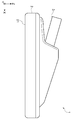
도 2는, 구강 내 센서의 정면도이다.
도 3은, 구강 내 센서의 저면도이다.
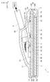
도 4는, 도 3의 IV-IV선을 따른 단면도이다.
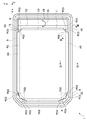
도 5는, 구강 내 센서의 내부 구조를 나타내는 도면이다.
도 6은, 도 5의 VI-VI선을 따른 단면도이다.
도 7은, 도 5의 VII-VII선을 따른 단면도이다.
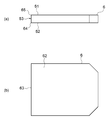
도 8은, 구강 내 센서의 제조 방법을 나타내는 도면이다.
도 9는, 구강 내 센서의 제조 방법을 나타내는 도면이다.
도 10은, 구강 내 센서의 제조 방법을 나타내는 도면이다.
도 11은, 구강 내 센서의 제조 방법을 나타내는 도면이다.
도 12는, 구강 내 센서의 변형예를 나타내는 도면이다.
도 13은, 구강 내 센서의 제조 방법의 변형예를 나타내는 도면이다. 1 is a plan view of an intraoral sensor according to an embodiment.
2 is a front view of the intraoral sensor.
3 is a bottom view of the intraoral sensor.
4 is a cross-sectional view taken along line IV-IV in FIG. 3.
5 is a view showing the internal structure of the intraoral sensor.
6 is a cross-sectional view taken along line VI-VI in FIG. 5.
7 is a cross-sectional view taken along line VII-VII in FIG. 5.
8 is a view showing a method for manufacturing an intraoral sensor.
9 is a view showing a method of manufacturing an intraoral sensor.
10 is a view showing a method of manufacturing an intraoral sensor.
11 is a view showing a method of manufacturing an intraoral sensor.
12 is a view showing a modification of the intraoral sensor.
13 is a view showing a modification of the method for manufacturing an intraoral sensor.
이하, 첨부 도면을 참조하여, 본 발명의 실시 형태에 대해 상세하게 설명한다. 설명에서, 동일 요소 또는 동일 기능을 가지는 요소에는, 동일 부호를 이용하는 것으로 하고, 중복하는 설명은 생략한다. Hereinafter, embodiments of the present invention will be described in detail with reference to the accompanying drawings. In description, the same code | symbol is used for the element which has the same element or the same function, and overlapping description is abbreviate | omitted.
도 1~도 7을 참조하여, 본 실시 형태에 관한 구강 내 센서(1)의 구성을 설명한다. 도 1은, 본 실시 형태에 관한 구강 내 센서(1)의 평면도이다. 도 2는, 구강 내 센서(1)의 정면도이다. 도 3은, 구강 내 센서(1)의 저면도이다. 도 4는, 도 3의 IV-IV선을 따른 단면도이다. 도 5는, 구강 내 센서(1)의 내부 구조를 나타내는 도면이다. 도 6은, 도 5의 VI-VI선을 따른 단면도이다. 도 7은, 도 5의 VII-VII선을 따른 단면도이다. 1 to 7, the configuration of the
구강 내 센서(1)는, 도 1~도 3에 나타내어지는 바와 같이, 본체부(2)와, 배선 케이블(3)을 구비하고 있다. 본체부(2)는, 검출면(21)을 가지고 있다. 배선 케이블(3)은, 본체부(2)에 고정되고, 본체부(2)에 전기적으로 접속되어 있다. 배선 케이블(3)은, 본체부(2)의 검출면(21)과는 반대측에 탈착 가능하게 고정되어 있다. The
본체부(2)는, 도 4에 나타내어지는 바와 같이, 지지 기판(4)과, 이미지 센서(5)와, FOP(파이버 옵티컬 플레이트)(6)와, 신틸레이터(7)와, 배선 기판(11)과, IC(12)와, 커넥터(13)와, 케이스(8)와, 완충재(9)를 구비하고 있다. The
지지 기판(4)은, 도 4 및 도 5에 나타내어지는 바와 같이, 다각형 판 모양을 나타내고 있다. 지지 기판(4)은, 제1 주면(主面)(41)과, 제2 주면(42)과, 복수의 측면(43)을 가지고 있다. 제1 주면(41)은, 다각 형상을 나타내고 있다. 제1 주면(41)은, 예를 들면 육각 형상을 나타내고 있다. 제2 주면(42)은, 다각 형상을 나타내고 있다. 제2 주면(42)은, 예를 들면 육각 형상을 나타내고 있다. 본 실시 형태에서는, 지지 기판(4)은, 6개의 측면(43)을 가지고 있다. The
제1 주면(41) 상에는, 배선 기판(11)이 배치되어 있다. 배선 기판(11) 상에는, IC(12) 및 커넥터(13)가 배치되어 있다. 제2 주면(42) 상에는, 배선, 및 이미지 센서(5)가 배치되어 있다. 배선은, 예를 들면, A/D 변환기 등의 회로이다. 이미지 센서(5) 상에는, FOP(6)가 배치되어 있다. FOP(6) 상에는, 신틸레이터(7)가 배치되어 있다. 지지 기판(4)의 재료는, 예를 들면 유리 또는 Si이다. On the first
이미지 센서(5)는, CMOS 이미지 센서이다. 이미지 센서(5)는, 다각형 판 모양을 나타내고 있다. 이미지 센서(5)는, 제1 주면(51)과, 제2 주면(52)과, 복수의 측면(53)을 가지고 있다. 제1 주면(51)은, 지지 기판(4)과 대향하고 있다. 제1 주면(51)은, 다각 형상을 나타내고 있다. 제1 주면(51)은, 예를 들면 육각 형상을 나타내고 있다. 제2 주면(52)은, FOP(6)와 대향하고 있다. 제2 주면(52)은, 다각 형상을 나타내고 있다. 제2 주면(52)은, 예를 들면 육각 형상을 나타내고 있다. 본 실시 형태에서는, 이미지 센서(5)는, 6개의 측면(53)을 가지고 있다. The
제1 주면(51)의 가장자리(54)와 제2 주면(52)의 가장자리(55)는, 제1 주면(51) 및 제2 주면(52)에 직교하는 방향인 Z축 방향으로부터 본 경우에, 서로 겹쳐져 있다. 각각의 측면(53)은, 제1 주면(51)의 가장자리(54)와 제2 주면(52)의 가장자리(55)를 연결하고 있다. 서로 이웃하는 측면(53)은, 복수의 능부(53a)를 구성하고 있다. 본 실시 형태에서는, 이미지 센서(5)는, 6개의 능부(53a)를 가지고 있다.When the
Z축에 직교하는 X축 방향에서의 이미지 센서(5)의 폭은, 예를 들면, 33.92mm이다. Z축 및 X축에 직교하는 Y축 방향에서의 이미지 센서(5)의 폭은, 예를 들면, 21.6mm이다. 이미지 센서(5)의 두께는, 예를 들면, 수μm~수십μm이다. Z축 방향으로부터 본 경우에, X축 방향에서의 이미지 센서(5)의 배선 케이블(3)측의 측면(53)은, 지지 기판(4)의 측면(43)보다도 내측에 마련되어 있다. Z축 방향으로부터 본 경우에, 이미지 센서(5)의 다른 측면(53)은, 지지 기판(4)의 다른 측면(43)과 겹쳐져 있다.The width of the
이미지 센서(5)는, 광 검출 영역(5a)을 가지고 있다. 광 검출 영역(5a)은, 복수의 화소로 구성되어 있다. 복수의 화소는, 소정의 화소 피치로 2차원으로 배열되어 있다. 광 검출 영역(5a)은, 다각 형상을 나타내고 있다. 광 검출 영역(5a)은, 예를 들면 육각 형상을 나타내고 있다. 광 검출 영역(5a)은, Z축 방향으로부터 본 경우에, 이미지 센서(5)의 외부 가장자리보다도 내측에 마련되어 있다. 광 검출 영역(5a)은, Z축 방향으로부터 본 경우에, 이미지 센서(5)의 제1 주면(51) 및 제2 주면(52)의 각각의 가장자리(54, 55)보다도 내측에 마련되어 있다. 광 검출 영역(5a)(화소)은, 입사광에 따라 전하가 발생하는 전하 발생 영역(광 감응 영역)이다. The
X축 방향에서의 광 검출 영역(5a)의 폭은, 예를 들면, 30mm이다. Y축 방향에서의 광 검출 영역(5a)의 폭은, 예를 들면, 20mm이다. 이미지 센서(5)는, 광 검출 영역(5a)에 의해 광상(光像)을 촬상하고, 얻어진 화상을 출력 화상 신호로서 출력한다. 이미지 센서(5)는, 와이어(14)에 의해서 지지 기판(4)의 제2 주면(42) 상에 배치된 배선과 전기적으로 접속되어 있다. The width of the
FOP(6)는, 이미지 센서(5)의 광 검출 영역(5a)을 덮고 있다. FOP(6)는, 복수의 광 파이버를 가지고 있다. 복수의 광 파이버는, 소정의 배열 피치로 2차원 배열되어 있고, 묶여져 있다. FOP(6)는, 묶여진 복수의 광 파이버에 의해서 광상(光像)을 전송한다. FOP(6)는, 입력 단면(端面)과, 출력 단면을 가지고 있다. 입력 단면은, 복수의 광 파이버의 일방의 단면으로 구성되어 있다. 출력 단면은, 복수의 광 파이버의 타방의 단면으로 구성되어 있다. FOP(6)는, 입력 단면으로부터 입력된 촬상 대상이 되는 광상을 출력 단면으로 전송한다. The
FOP(6)는, 다각형 판 모양을 나타내고 있다. FOP(6)는, 제1 주면(61)과, 제2 주면(62)과, 복수의 측면(63)을 가지고 있다. 제1 주면(61)은, 이미지 센서(5)와 대향하고 있다. 제1 주면(61)은, 다각 형상을 나타내고 있다. 제1 주면(61)은, 예를 들면 육각 형상을 나타내고 있다. 제2 주면(62)은, 신틸레이터(7)와 대향하고 있다. 제2 주면(62)은, 다각 형상을 나타내고 있다. 제2 주면(62)은, 예를 들면 육각 형상을 나타내고 있다. 본 실시 형태에서는, FOP(6)는, 6개의 측면(63)을 가지고 있다. The
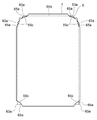
제1 주면(61)의 가장자리(64)와 제2 주면(62)의 가장자리(65)는, Z축 방향으로부터 본 경우에, 서로 겹쳐져 있다. 제2 주면(62)의 가장자리(65)는, 복수의 모서리부(65a)와, 복수의 변부(65b)로 구성되어 있다. 복수의 변부(65b)는, 서로 이웃하는 모서리부(65a)를 연결하고 있다. 모서리부(65a)는, 제2 주면(62)의 가장자리(65)의 일부이다. 모서리부(65a)는, 제2 주면(62)의 가장자리(65)의 모서리의 정점(頂点)으로부터 소정의 길이를 가지는 선분이다. 모서리부(65a)의 길이는, 예를 들면, 0.9mm이다. 각각의 측면(63)은, 제1 주면(61)의 가장자리(64)와 제2 주면(62)의 가장자리(65)를 연결하고 있다. 서로 이웃하는 측면(63)은, 복수의 능부(63a)를 구성하고 있다. 본 실시 형태에서는, 가장자리(65)는, 6개의 모서리부(65a)와, 6개의 변부(65b)를 포함하고 있다. 본 실시 형태에서는, FOP(6)는, 6개의 능부(63a)를 포함하고 있다. The
X축 방향에서의 FOP(6)의 폭은, 예를 들면, 33mm이다. Y축 방향에서의 FOP(6)의 폭은, 예를 들면, 21.8mm이다. FOP(6)의 두께는, 예를 들면, 1.5mm이다. Z축 방향으로부터 본 경우에, X축 방향에서의 FOP(6)의 배선 케이블(3)측의 측면(63)은, 이미지 센서(5)의 측면(53)보다도 내측에 마련되어 있다. Z축 방향으로부터 본 경우에, FOP(6)의 다른 측면(63)은, 이미지 센서(5)의 다른 측면(53)과 겹쳐져 있다. The width of the
신틸레이터(7)는, 이미지 센서(5)의 광 검출 영역(5a)을 덮도록, FOP(6)의 제2 주면(62)과 복수의 측면(63)에 마련되어 있다. 신틸레이터(7)는, FOP(6)의 제2 주면(62) 상에서 펼쳐져 있고, 제2 주면(62)의 가장자리(65)를 통해서 복수의 측면(63) 상에 이르고 있다. 신틸레이터(7)는, 방사선의 입사에 의해 형광(신틸레이션광)을 발(發)한다. The
신틸레이터(7)는, 도 5 및 도 6에 나타내어지는 바와 같이, FOP(6)의 제2 주면(62)으로부터 변부(65b)를 거쳐 측면(63)에 이르고 있다. 신틸레이터(7)는, FOP(6)의 각 모서리부(65a)에는 마련되어 있지 않다. 신틸레이터(7)는, 도 5 및 도 7에 나타내어지는 바와 같이, FOP(6)의 제2 주면(62)에서, 모서리부(65a)보다도 내측에 마련되어 있다. 신틸레이터(7)는, FOP(6)의 제2 주면(62)에서, 각 모서리부(65a)에 의해 끼인 영역(65c)에는 마련되어 있지 않다. FOP(6)의 제2 주면(62)에서의 각 모서리부(65a)에 의해 끼인 영역(65c)은, 노출되어 있다.The
신틸레이터(7)는, FOP(6)의 각 능부(63a)에는 마련되어 있지 않다. 신틸레이터(7)는, FOP(6)의 측면(63)에서, 능부(63a)에 이르지 않는다. 신틸레이터(7)는, FOP(6)의 측면(63)에서의 각 능부(63a)로부터의 소정 범위의 영역에는, 마련되어 있지 않다. FOP(6)의 측면(63)에서의 각 능부(63a)로부터의 소정 범위의 영역은, 노출되어 있다. FOP(6)의 측면(63)에서의 각 능부(63a)로부터의 소정 범위의 영역은, 예를 들면 각 능부(63a)로부터 모서리부(65a)의 길이와 동일한 거리까지의 범위이다. The
이상과 같이, 신틸레이터(7)는, FOP(6)의 각 모서리부(65a)와 각 능부(63a)가 노출되도록, FOP(6)의 제2 주면(62)과 복수의 측면(63)에 마련되어 있다. 신틸레이터(7)의 두께는, 예를 들면, 100μm이다. 신틸레이터(7)는, 신틸레이터 재료로 이루어져 있다. 신틸레이터 재료는, CsI:Tl 또는 CsI:Na 등과 같은 CsI(아이오딘화 세슘)를 주성분으로 한다. CsI는, 다수의 침상(針狀) 결정(기둥 모양 결정)이 늘어선 구조를 가지고 있다. As described above, the
다시, 도 4 및 도 5를 참조한다. 배선 기판(11)은, 지지 기판(4)의 제1 주면(41) 상에 배치되어 있다. 배선 기판(11)은, 표면에 전극 및 배선 등이 배치된 프린트 기판이다. 배선 기판(11)의 표면 상에 배치된 전극 또는 배선은, 지지 기판(4) 상에 배치된 배선과 전기적으로 접속되어 있다. 즉, 배선 기판(11)에 배치된 전극 또는 배선은, 이미지 센서(5)와 전기적으로 접속되어 있다. Again, reference is made to FIGS. 4 and 5. The
배선 기판(11)은, 다각형 판 모양을 나타내고 있다. Z축 방향으로부터 본 경우에, 배선 기판(11)의 각각의 측면은, 지지 기판(4)의 각각의 측면(43)과 겹쳐져 있다. 배선 기판(11)의 두께는, 예를 들면, 1mm이다. The
IC(12)는, 배선 기판(11) 상에 배치되어 있다. IC(12)는, 배선 기판(11)에 배치된 전극 또는 배선을 통해서, 이미지 센서(5)와 전기적으로 접속되어 있다. 커넥터(13)는, 배선 기판(11) 상에 배치되어 있다. 커넥터(13)는, IC(12)와 전기적으로 접속되어 있다. The
케이스(8)는, 지지 기판(4)과, 이미지 센서(5)와, FOP(6)와, 신틸레이터(7)와, 배선 기판(11)과, IC(12)와, 커넥터(13)를 수용하고 있다. 케이스(8)의 내부 공간은, Z축 방향으로부터 본 경우에, 이미지 센서(5), FOP(6), 및 신틸레이터(7)를 포함하는 구조체의 외부 가장자리를 따르도록 형성되어 있다. The
케이스(8)는, 제1 케이스(81)와, 제2 케이스(82)를 가지고 있다. 제1 케이스(81)에는, 배선 케이블(3)을 고정하는 고정부(83)가 마련되어 있다. 제1 케이스(81) 및 제2 케이스(82)는, 서로 맞물려 있다. 케이스(8)의 재료는, 예를 들면 내충격성을 가지는 ABS 수지 등이다. The
완충재(9)는, 이미지 센서(5)와, FOP(6)와, 신틸레이터(7)를 포함하는 구조체와, 케이스(8)와의 사이에 배치되어 있다. 완충재(9)는, 당해 구조체와 접촉하고 있다. 완충재(9)는, 적어도, X축 방향에서의 당해 구조체의 배선 케이블(3)의 도출 방향과는 반대측과 케이스(8)와의 사이에 배치되어 있다. 이 경우, X축 방향에서의 당해 구조체의 배선 케이블(3)의 도출 방향과는 반대측과 케이스(8)와의 사이에는, 완충재(9)가 배치되는 간극(예를 들면, 500μm의 간극)이 마련되어 있다. 완충재(9)는, Z축 방향으로부터 본 경우에, 이미지 센서(5)와, FOP(6)와, 신틸레이터(7)를 포함하는 구조체의 전체 둘레에 걸쳐 배치되어 있어도 괜찮다. 이 경우, Y축 방향에서의 당해 구조체의 양측과 케이스(8)와의 사이에는, 각각 완충재(9)가 배치되는 간극(예를 들면, 200μm의 간극)이 더 마련되어 있다. 완충재(9)의 재료는, 예를 들면 실리콘 고무 등이다. The
배선 케이블(3)은, 케이스(8)의 고정부(83)에 고정되어 있다. 배선 케이블(3)은, 커넥터(13)와 전기적으로 접속되어 있다. 배선 케이블(3)은, USB 케이블이며, 본체부(2)를 예를 들면 PC에 접속하고 있다. 배선 케이블(3)은, 고정부(83)에 탈착 가능하게 고정되어 있다. The
이상과 같이 구성된 구강 내 센서(1)는, 환자의 구강 내에 삽입되고, 본체부(2)의 검출면(21)이 이빨이나 잇몸을 통해서 구강 외에 배치된 방사선원(放射線源)에 대향하도록 배치된다. 방사선원으로부터 방사선이 방사되면, 방사선이 이빨이나 잇몸을 투과하여 신틸레이터(7)에 입사한다. 신틸레이터(7)는, 입사된 방사선의 강도에 따라서 형광을 발한다. 이 형광은, FOP(6)에 의해서 이미지 센서(5)의 광 검출 영역(5a)에 전달되어, 이미지 센서(5)에서 전기 신호로 변환된다. 이미지 센서(5)에 의해 변환된 전기 신호는, 와이어(14), 지지 기판(4), 배선 기판(11), 및 배선 케이블(3) 등을 통해서, PC에 송신된다. 이 전기 신호는, PC에서 이빨이나 잇몸의 투시 화상으로 변환된다. The
이상 설명한 바와 같이, 구강 내 센서(1)에서는, 신틸레이터(7)가, FOP(6)의 각 모서리부(65a)와 각 능부(63a)가 노출되도록, 제2 주면(62)과 복수의 측면(63)에 마련되어 있다. 즉, 신틸레이터(7)는, FOP(6)의 각 모서리부(65a) 상 및 각 능부(63a) 상에 위치하고 있지 않다. 따라서, 구강 내 센서(1)가 외부로부터 충격을 받는 경우에도, 해당 충격이 신틸레이터(7)에 전해지기 어렵고, 신틸레이터(7)는 벗겨지기 어렵다. 이 결과, 신틸레이터(7)의 벗겨짐을 억제할 목적으로, 케이스(8)의 외형이 크게 될 필요는 없어, 구강 내 센서(1)의 대형화가 억제된다. 상술한 바와 같이, 신틸레이터(7)가 벗겨지기 어려우므로, 구강 내 센서(1)의 신뢰성이 향상되어 있다. As described above, in the
구강 내 센서(1)와 같이 신틸레이터(7)가 FOP(6)의 측면(63)에도 마련되어 있는 경우에는, 구강 내 센서(1)의 외부로부터의 충격이 신틸레이터(7)에 전해지기 쉽다. 이 때문에, 신틸레이터(7)가, FOP(6)의 각 모서리부(65a) 상 및 각 능부(63a)로부터 벗겨지기 쉬워진다. 구강 내 센서(1)에서는, 상술한 바와 같이, 신틸레이터(7)가, FOP(6)의 각 모서리부(65a) 상 및 각 능부(63a) 상에 위치하고 있지 않으므로, FOP(6)로부터 벗겨지기 어렵다. 즉, 신틸레이터(7)가 FOP(6)의 측면(63)에도 마련되어 있는 경우에는, 상술한 바와 같은 신틸레이터(7)가 벗겨지기 어려운 효과가 특히 현저하게 된다. When the
구강 내 센서(1)에서는, 신틸레이터(7)가, CsI를 주성분으로 하는 신틸레이터 재료로 이루어져 있다. 이 경우, 신틸레이터(7)를 증착에 의해 형성하는 것이 가능하기 때문에, 신틸레이터(7)를 용이하게 마련할 수 있다. CsI는, 다수의 침상 결정이 늘어선 구조를 가지고 있다. 입상 결정에 비해, 각각의 침상 결정에 의해 발하여진 광은, 주위로 퍼지기 어렵다. 이것에 의해, 각각의 침상 결정에 의해 발하여진 광이 보다 정확하게 각각의 침상 결정에 대응하는 이미지 센서(5)의 위치에 전달된다. 따라서, 이미지 센서(5)의 화상의 해상도를 향상시킬 수 있다. In the
구강 내 센서(1)에서는, 완충재(9)가, 이미지 센서(5)와, FOP(6)와, 신틸레이터(7)를 포함하는 구조체와, 케이스(8)와의 사이에 배치되어 있다. 이 구성에 의하면, 구강 내 센서(1)가 받는 외부로부터의 충격이, 신틸레이터(7)에 전해지기 어렵다. 따라서, 신틸레이터(7)의 벗겨짐이 보다 한층 확실히 억제된다.In the
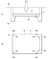
다음으로, 도 8~도 11을 참조하여, 본 실시 형태에 관한 구강 내 센서(1)의 제조 방법을 설명한다. 도 8~도 11은, 구강 내 센서(1)의 제조 방법을 나타내는 도면이다. 도 8 및 도 9에서, (a)는, 정면도이고, (b)는, 저면도이다. 도 8에 나타내어지는 바와 같이, 우선, FOP(6)가 준비된다. 이어서, 도 9에 나타내어지는 바와 같이, FOP(6)가, 방향 D1을 따라서 챔버(20) 내에 배치된 지그(30)에 재치된다. 지그(30)는, FOP(6)의 각 모서리부(65a)를 덮는 형상으로 되어 있다. 지그(30)는, FOP(6)의 제2 주면(62)에서의 각 모서리부(65a)에 의해 끼인 영역(65c)을 덮는 형상으로 되어 있다. Next, a method for manufacturing the
이어서, 도 10에 나타내어지는 바와 같이, 신틸레이터(7)가 마련된다. 구체적으로는, 신틸레이터(7)는, FOP(6)의 각 모서리부(65a)와 각 능부(63a)가 노출되도록, 제2 주면(62)과 복수의 측면(63)에 마련된다. 신틸레이터(7)가 마련될 때에는, 복수의 모서리부(65a)는, FOP(6)를 지지하는 지그(30)에 의해 덮여진다. 그리고, 지그(30)가 마스크가 되어, 신틸레이터(7)를 구성하는 신틸레이터 재료가 증착된다. 이 때, 신틸레이터(7)는, FOP(6)의 변부(65b)를 구성하는 측면(63)에도 증착된다. 신틸레이터 재료는, CsI를 주성분으로 하고 있다. 이어서, 방향 D2를 따라서 FOP(6)가 지그(30)로부터 떨어진다. 그 결과, 도 11에 나타내어지는 바와 같이, 신틸레이터(7)가 증착된 FOP(6)가 얻어진다. Next, as shown in FIG. 10, the
이어서, 신틸레이터(7)가 증착된 FOP(6)가, 지지 기판(4) 상에 배치된 이미지 센서(5) 상에 배치된다. 지지 기판(4)은, 이미지 센서(5)의 제조 공정에서 이미지 센서(5)를 지지하는 기판이다. 이어서, 지지 기판(4), 이미지 센서(5), FOP(6), 및 신틸레이터(7)가, 케이스(8)의 제1 케이스(81) 내에 수용된다. 이 때, 제1 케이스(81)에는, IC(12) 및 커넥터(13)가 배치된 배선 기판(11)이 이미 수용되어 있다.Subsequently, the
이어서, 지지 기판(4)과 배선 기판(11)이 고정된다. 이것과 함께, 지지 기판(4)에 배치된 배선과 배선 기판(11)에 배치된 전극 또는 배선이 전기적으로 접속된다. 이어서, 와이어(14)에 의해서, 지지 기판(4)에 배치된 배선과 이미지 센서(5)가 전기적으로 접속된다. 이어서, 제2 케이스(82)가 제1 케이스(81)에 맞물린다. 이어서, 배선 케이블(3)이, 케이스(8)의 고정부(83)에 장착되어 고정됨과 아울러, 커넥터(13)와 전기적으로 접속된다.Subsequently, the supporting
이상 설명한 바와 같이, 구강 내 센서(1)의 제조 방법에 의하면, 신틸레이터(7)가, FOP(6)의 각 모서리부(65a)와 각 능부(63a)가 노출되도록, 제2 주면(62)과 복수의 측면(63)에 마련된다. 따라서, 상술한 바와 같이, 대형화가 억제되어 있음과 아울러 신뢰성이 향상되어 있는 구강 내 센서(1)가 얻어진다. As described above, according to the manufacturing method of the
구강 내 센서(1)의 제조 방법은, 신틸레이터(7)를 마련할 때에, FOP(6)를 지지하는 지그(30)에 의해, 복수의 모서리부(65a)를 덮고, 지그(30)를 마스크로 하여, 신틸레이터(7)를 구성하는 신틸레이터 재료를 증착하고 있다. 이 경우, 복수의 모서리부(65a)를 덮는 마스크를 새롭게 준비할 필요가 없다. 따라서, 구강 내 센서(1)의 제조 공정이 간소화된다.In the method for manufacturing the
구강 내 센서(1)의 제조 방법에서는, 신틸레이터 재료가, CsI를 주성분으로 하고 있다. 이 경우, 증착에 의한 신틸레이터(7)의 형성이 간이하다. In the method for manufacturing the
이상, 본 발명의 일 실시 형태에 대해 설명했지만, 본 발명은, 상술한 실시 형태에 한정되는 것은 아니다. The embodiments of the present invention have been described above, but the present invention is not limited to the above-described embodiments.
구강 내 센서(1)는, 배선 케이블(3) 대신에 도시하지 않은 무선 통신 장치를 구비하고 있어도 괜찮다. 이 때, 구강 내 센서(1)는, 무선 통신 장치에 의해서 이미지 센서(5)로부터의 전기 신호를 외부로 송신한다. The
FOP(6)의 제1 주면(61) 및 제2 주면(62)은, 육각 형상을 나타내지 않아도 된다. FOP(6)의 제1 주면(61) 및 제2 주면(62)은, 다각 형상을 나타내고 있으면 된다. FOP(6)의 제1 주면(61) 및 제2 주면(62)은, 도 12에 나타내어지는 바와 같이, 예를 들면 팔각형 모양을 나타내고 있어도 괜찮다. The first
이미지 센서(5)의 제1 주면(51) 및 제2 주면(52)은, 육각 형상을 나타내고 있지 않아도 된다. 이미지 센서(5)의 제1 주면(51) 및 제2 주면(52)은, 다각 형상을 나타내고 있어도 괜찮다. 이미지 센서(5)의 제1 주면(51) 및 제2 주면(52)은, 예를 들면 팔각형 모양을 나타내고 있어도 괜찮다.The first
지지 기판(4)의 제1 주면(41) 및 제2 주면(42)은, 육각 형상을 나타내고 있지 않아도 된다. 지지 기판(4)의 제1 주면(41) 및 제2 주면(42)은, 다각 형상을 나타내고 있어도 괜찮다. 지지 기판(4)의 제1 주면(41) 및 제2 주면(42)은, 예를 들면 팔각형 모양을 나타내고 있어도 괜찮다. The first
신틸레이터(7)는, FOP(6)의 측면(63)에서의 각 능부(63a)를 제외한 영역의 전부에 마련되어 있지 않아도 된다. 신틸레이터(7)는, FOP(6)의 측면(63)에서의 각 능부(63a)를 제외한 영역의 일부에는 마련되어 있지 않아도 된다. FOP(6)의 측면(63)에서의 각 능부(63a)를 제외한 영역의 일부가, 노출되어 있어도 괜찮다. The
구강 내 센서(1)의 제조 방법은, 신틸레이터(7)를 마련할 때에, FOP(6)를 지지하는 지그(30)에 의해, 모든 모서리부(65a)를 덮지 않아도 된다. 지그(30)는, 도 13에 나타내어지는 바와 같이, 일부의 모서리부(65a) 및 FOP(6)의 변부(65b)의 일부를 덮음과 아울러, FOP(6)를 지지해도 괜찮다. 이 때, FOP(6)의 다른 모서리부(65a)는, 마스크(40)에 의해서 덮여져 있으면 좋다. 지그(30)에 의해서 덮여져 지지되는 변부(65b)의 상기 일부의 위치는, 변부(65b) 상의 여러가지 위치로 할 수 있다. 예를 들면, 변부(65b)의 상기 일부는, 서로 이웃하는 모서리부(65a)의 사이의 변부(65b) 중, 어느 하나의 변부(65b) 상에 위치하고 있어도 괜찮다. In the method for manufacturing the
1 - 구강 내 센서
5 - 이미지 센서
5a - 광 검출 영역
6 - FOP
7 - 신틸레이터
8 - 케이스
9 - 완충재
30 - 지그
40 - 마스크
61 - 제1 주면
62 - 제2 주면
63 - 측면
63a - 능부
64, 65 - 가장자리
65a - 모서리부
65b - 변부1-Intraoral sensor 5-Image sensor
5a-Light detection area 6-FOP
7-Scintillator 8-Case
9-cushioning material 30-jig
40-Mask 61-1st main surface
62-Second main surface 63-Side
63a-
65a-
Claims (6)
광 검출 영역을 가지는 이미지 센서와,
상기 광 검출 영역을 덮도록, 상기 이미지 센서 상에 배치되어 있는 파이버 옵티컬 플레이트와,
파이버 옵티컬 플레이트 상에 배치되어 있는 신틸레이터(scintillator)와,
상기 이미지 센서와, 상기 파이버 옵티컬 플레이트와, 상기 신틸레이터를 수용하고 있는 케이스를 구비하며,
상기 파이버 옵티컬 플레이트는,
상기 이미지 센서와 대향하고 있음과 아울러, 다각 형상을 나타내고 있는 제1 주면(主面)과,
상기 신틸레이터와 대향하고 있음과 아울러, 다각 형상을 나타내고 있는 제2 주면과,
상기 제1 주면의 가장자리와 상기 제2 주면의 가장자리를 연결하고 있는 복수의 측면을 가지며,
상기 제2 주면의 상기 가장자리는, 복수의 모서리부와, 서로 이웃하는 상기 모서리부를 연결하고 있는 복수의 변부(邊部)로 구성되어 있고,
상기 신틸레이터는, 각 상기 모서리부와, 서로 이웃하는 상기 측면으로 구성되는 각 능부(稜部)가 노출되도록, 상기 제2 주면과 상기 복수의 측면에 마련되어 있는 구강 내 센서.As an intraoral sensor,
An image sensor having a light detection area,
A fiber optical plate disposed on the image sensor to cover the light detection area,
A scintillator disposed on a fiber optical plate,
And a case accommodating the image sensor, the fiber optical plate, and the scintillator,
The fiber optical plate,
A first main surface facing the image sensor and having a polygonal shape,
A second main surface facing the scintillator and exhibiting a polygonal shape;
It has a plurality of side surfaces connecting the edge of the first main surface and the edge of the second main surface,
The edge of the second main surface is composed of a plurality of edge portions and a plurality of side portions connecting the edge portions adjacent to each other,
The scintillator is an intraoral sensor provided on the second main surface and the plurality of side surfaces such that each corner portion and each trough portion composed of the side surfaces adjacent to each other are exposed.
상기 신틸레이터는, CsI를 주성분으로 하는 신틸레이터 재료로 이루어지는 구강 내 센서. The method according to claim 1,
The scintillator is an intraoral sensor made of a CsI-based scintillator material.
상기 이미지 센서와, 상기 파이버 옵티컬 플레이트와, 상기 신틸레이터를 포함하는 구조체와, 상기 케이스와의 사이에 배치되고, 상기 구조체와 접촉하는 완충재를 더 구비하는 구강 내 센서.The method according to claim 1 or claim 2,
An intraoral sensor further comprising a buffer material that is disposed between the image sensor, the fiber optical plate, the structure including the scintillator, and the case, and contacts the structure.
상기 구강 내 센서는, 이미지 센서와 파이버 옵티컬 플레이트와 신틸레이터를 포함하는 구조체와, 상기 구조체를 수용하고 있는 케이스를 구비하며,
상기 파이버 옵티컬 플레이트로서,
다각 형상을 나타내고 있는 제1 주면과, 상기 제1 주면과 대향하고 있음과 아울러 다각 형상을 나타내고 있는 제2 주면과, 상기 제1 주면의 가장자리와 상기 제2 주면의 가장자리를 연결하고 있는 복수의 측면을 가지며,
상기 제2 주면의 상기 가장자리가, 복수의 모서리부와, 서로 이웃하는 상기 모서리부를 연결하고 있는 복수의 변부로 구성되어 있는 파이버 옵티컬 플레이트를 준비하며,
상기 신틸레이터를, 각 상기 모서리부와, 서로 이웃하는 상기 측면으로 구성되는 각 능부가 노출되도록, 상기 제2 주면과 상기 복수의 측면에 마련하는 구강 내 센서의 제조 방법.As a method of manufacturing an intraoral sensor,
The intraoral sensor includes a structure including an image sensor, a fiber optical plate, and a scintillator, and a case housing the structure,
As the fiber optical plate,
A first main surface showing a polygonal shape, a second main surface facing the first main surface, and a plurality of side surfaces connecting an edge of the first main surface and an edge of the second main surface while facing the first main surface Have,
The edge of the second main surface is provided with a fiber optical plate consisting of a plurality of corners, and a plurality of edges connecting the corners adjacent to each other,
A method of manufacturing an intraoral sensor, wherein the scintillator is provided on the second main surface and the plurality of side surfaces such that each of the corner portions and each twill portion composed of the side surfaces adjacent to each other are exposed.
상기 신틸레이터를 마련할 때에,
상기 파이버 옵티컬 플레이트를 지지하는 지그에 의해, 상기 복수의 모서리부를 덮으며,
상기 지그를 마스크로 하여, 상기 신틸레이터를 구성하는 신틸레이터 재료를 증착하는 구강 내 센서의 제조 방법.The method according to claim 4,
When providing the scintillator,
The jig for supporting the optical fiber plate, covering the plurality of corners,
Using the jig as a mask, a method for manufacturing an intraoral sensor for depositing a scintillator material constituting the scintillator.
상기 신틸레이터 재료는, CsI를 주성분으로 하는 구강 내 센서의 제조 방법.The method according to claim 5,
The scintillator material is a method for manufacturing an intraoral sensor containing CsI as a main component.
Applications Claiming Priority (3)
| Application Number | Priority Date | Filing Date | Title |
|---|---|---|---|
| JP2017165261A JP6515153B2 (en) | 2017-08-30 | 2017-08-30 | Intraoral sensor and method of manufacturing intraoral sensor |
| JPJP-P-2017-165261 | 2017-08-30 | ||
| PCT/JP2018/031361 WO2019044701A1 (en) | 2017-08-30 | 2018-08-24 | Intraoral sensor and method for producing intraoral sensor |
Publications (2)
| Publication Number | Publication Date |
|---|---|
| KR20200046030A true KR20200046030A (en) | 2020-05-06 |
| KR102554082B1 KR102554082B1 (en) | 2023-07-12 |
Family
ID=65525701
Family Applications (1)
| Application Number | Title | Priority Date | Filing Date |
|---|---|---|---|
| KR1020207005389A KR102554082B1 (en) | 2017-08-30 | 2018-08-24 | Intraoral sensor, and manufacturing method of intraoral sensor |
Country Status (5)
| Country | Link |
|---|---|
| US (1) | US11576632B2 (en) |
| EP (1) | EP3677188B1 (en) |
| JP (1) | JP6515153B2 (en) |
| KR (1) | KR102554082B1 (en) |
| WO (1) | WO2019044701A1 (en) |
Families Citing this family (2)
| Publication number | Priority date | Publication date | Assignee | Title |
|---|---|---|---|---|
| JP6515152B2 (en) * | 2017-08-30 | 2019-05-15 | 浜松ホトニクス株式会社 | Intraoral sensor and method of manufacturing intraoral sensor |
| JP2024048855A (en) * | 2022-09-28 | 2024-04-09 | 浜松ホトニクス株式会社 | Intraoral imaging device |
Citations (6)
| Publication number | Priority date | Publication date | Assignee | Title |
|---|---|---|---|---|
| JPH08275942A (en) * | 1995-02-24 | 1996-10-22 | Loral Fairchild Corp | Central reading oral cavity picture sensor |
| JP2009500814A (en) * | 2005-07-01 | 2009-01-08 | ウードゥヴェ セミコンダクターズ | Dental intraoral radiation image sensor with optical fiber plate |
| US20130043397A1 (en) * | 2010-06-04 | 2013-02-21 | Hamamatsu Photonics K.K. | Scintillator panel, and radiographic image sensor |
| US20140023177A1 (en) * | 2012-07-17 | 2014-01-23 | Cyber Medical Imaging, Inc. | Intraoral Radiographic Sensors with Cables Having Increased User Comfort and Methods of Using the Same |
| JP2014153074A (en) * | 2013-02-05 | 2014-08-25 | Hamamatsu Photonics Kk | Radiation image conversion panel manufacturing method and radiation image conversion panel |
| US20140367578A1 (en) * | 2011-06-16 | 2014-12-18 | Forstgarten International Holding Gmbh | X-ray image sensor |
Family Cites Families (3)
| Publication number | Priority date | Publication date | Assignee | Title |
|---|---|---|---|---|
| JPS61225684A (en) * | 1985-03-29 | 1986-10-07 | Hamamatsu Photonics Kk | Scintillation fiber plate and manufacture thereof |
| US5434418A (en) * | 1992-10-16 | 1995-07-18 | Schick; David | Intra-oral sensor for computer aided radiography |
| US8614421B2 (en) * | 2011-03-07 | 2013-12-24 | Teledyne Dalsa Inc. | Method and system for assembly of glass substrate-based radiological imaging sensor |
-
2017
- 2017-08-30 JP JP2017165261A patent/JP6515153B2/en active Active
-
2018
- 2018-08-24 EP EP18850950.9A patent/EP3677188B1/en active Active
- 2018-08-24 WO PCT/JP2018/031361 patent/WO2019044701A1/en unknown
- 2018-08-24 KR KR1020207005389A patent/KR102554082B1/en active IP Right Grant
- 2018-08-24 US US16/641,789 patent/US11576632B2/en active Active
Patent Citations (6)
| Publication number | Priority date | Publication date | Assignee | Title |
|---|---|---|---|---|
| JPH08275942A (en) * | 1995-02-24 | 1996-10-22 | Loral Fairchild Corp | Central reading oral cavity picture sensor |
| JP2009500814A (en) * | 2005-07-01 | 2009-01-08 | ウードゥヴェ セミコンダクターズ | Dental intraoral radiation image sensor with optical fiber plate |
| US20130043397A1 (en) * | 2010-06-04 | 2013-02-21 | Hamamatsu Photonics K.K. | Scintillator panel, and radiographic image sensor |
| US20140367578A1 (en) * | 2011-06-16 | 2014-12-18 | Forstgarten International Holding Gmbh | X-ray image sensor |
| US20140023177A1 (en) * | 2012-07-17 | 2014-01-23 | Cyber Medical Imaging, Inc. | Intraoral Radiographic Sensors with Cables Having Increased User Comfort and Methods of Using the Same |
| JP2014153074A (en) * | 2013-02-05 | 2014-08-25 | Hamamatsu Photonics Kk | Radiation image conversion panel manufacturing method and radiation image conversion panel |
Also Published As
| Publication number | Publication date |
|---|---|
| US11576632B2 (en) | 2023-02-14 |
| US20200261040A1 (en) | 2020-08-20 |
| EP3677188B1 (en) | 2023-06-14 |
| JP2019045175A (en) | 2019-03-22 |
| EP3677188A1 (en) | 2020-07-08 |
| EP3677188A4 (en) | 2021-05-05 |
| JP6515153B2 (en) | 2019-05-15 |
| KR102554082B1 (en) | 2023-07-12 |
| WO2019044701A1 (en) | 2019-03-07 |
Similar Documents
| Publication | Publication Date | Title |
|---|---|---|
| US7615757B2 (en) | Semiconductor radiological detector and semiconductor radiological imaging apparatus | |
| JP5693174B2 (en) | Radiation detection apparatus and radiation detection system | |
| JP6231778B2 (en) | Electrical device and radiation inspection equipment | |
| US10156641B2 (en) | Radiation image sensing apparatus and radiation image sensing system | |
| RU2647206C1 (en) | Sensor device and visualization system for detecting radiation signals | |
| CN107850678B (en) | Detector unit for a detector array of a radiation imaging modality | |
| KR102554082B1 (en) | Intraoral sensor, and manufacturing method of intraoral sensor | |
| US20230038637A1 (en) | Radiation detector, radiation detector manufacturing method, and image processing method | |
| JP2007155564A (en) | Radiation detector and radiation image detector | |
| US20140367578A1 (en) | X-ray image sensor | |
| KR102557424B1 (en) | Intraoral sensor, and manufacturing method of intraoral sensor | |
| US10191270B2 (en) | Imaging unit and endoscope apparatus | |
| EP3011907B1 (en) | Production method for radiation detection unit | |
| JP6373624B2 (en) | Array substrate, radiation detector, and method of manufacturing radiation detector | |
| JP7062362B2 (en) | Radiation detector and radiation detector | |
| EP3011906A1 (en) | Radiation detection module and radiation detection unit | |
| KR20230072148A (en) | Intraoral X-ray sensor and manufacturing method thereof | |
| WO2018110184A1 (en) | Intraoral sensor |
Legal Events
| Date | Code | Title | Description |
|---|---|---|---|
| A201 | Request for examination | ||
| E902 | Notification of reason for refusal | ||
| E701 | Decision to grant or registration of patent right |