KR20200046021A - Liquid hydrogen delivery system - Google Patents
Liquid hydrogen delivery system Download PDFInfo
- Publication number
- KR20200046021A KR20200046021A KR1020207004415A KR20207004415A KR20200046021A KR 20200046021 A KR20200046021 A KR 20200046021A KR 1020207004415 A KR1020207004415 A KR 1020207004415A KR 20207004415 A KR20207004415 A KR 20207004415A KR 20200046021 A KR20200046021 A KR 20200046021A
- Authority
- KR
- South Korea
- Prior art keywords
- liquid hydrogen
- tube
- delivery system
- cold
- hydrogen delivery
- Prior art date
Links
Images


Classifications
-
- F—MECHANICAL ENGINEERING; LIGHTING; HEATING; WEAPONS; BLASTING
- F17—STORING OR DISTRIBUTING GASES OR LIQUIDS
- F17C—VESSELS FOR CONTAINING OR STORING COMPRESSED, LIQUEFIED OR SOLIDIFIED GASES; FIXED-CAPACITY GAS-HOLDERS; FILLING VESSELS WITH, OR DISCHARGING FROM VESSELS, COMPRESSED, LIQUEFIED, OR SOLIDIFIED GASES
- F17C13/00—Details of vessels or of the filling or discharging of vessels
- F17C13/002—Details of vessels or of the filling or discharging of vessels for vessels under pressure
-
- F—MECHANICAL ENGINEERING; LIGHTING; HEATING; WEAPONS; BLASTING
- F17—STORING OR DISTRIBUTING GASES OR LIQUIDS
- F17C—VESSELS FOR CONTAINING OR STORING COMPRESSED, LIQUEFIED OR SOLIDIFIED GASES; FIXED-CAPACITY GAS-HOLDERS; FILLING VESSELS WITH, OR DISCHARGING FROM VESSELS, COMPRESSED, LIQUEFIED, OR SOLIDIFIED GASES
- F17C5/00—Methods or apparatus for filling containers with liquefied, solidified, or compressed gases under pressures
- F17C5/02—Methods or apparatus for filling containers with liquefied, solidified, or compressed gases under pressures for filling with liquefied gases
-
- B—PERFORMING OPERATIONS; TRANSPORTING
- B23—MACHINE TOOLS; METAL-WORKING NOT OTHERWISE PROVIDED FOR
- B23P—METAL-WORKING NOT OTHERWISE PROVIDED FOR; COMBINED OPERATIONS; UNIVERSAL MACHINE TOOLS
- B23P15/00—Making specific metal objects by operations not covered by a single other subclass or a group in this subclass
-
- F—MECHANICAL ENGINEERING; LIGHTING; HEATING; WEAPONS; BLASTING
- F16—ENGINEERING ELEMENTS AND UNITS; GENERAL MEASURES FOR PRODUCING AND MAINTAINING EFFECTIVE FUNCTIONING OF MACHINES OR INSTALLATIONS; THERMAL INSULATION IN GENERAL
- F16L—PIPES; JOINTS OR FITTINGS FOR PIPES; SUPPORTS FOR PIPES, CABLES OR PROTECTIVE TUBING; MEANS FOR THERMAL INSULATION IN GENERAL
- F16L9/00—Rigid pipes
- F16L9/02—Rigid pipes of metal
-
- F—MECHANICAL ENGINEERING; LIGHTING; HEATING; WEAPONS; BLASTING
- F16—ENGINEERING ELEMENTS AND UNITS; GENERAL MEASURES FOR PRODUCING AND MAINTAINING EFFECTIVE FUNCTIONING OF MACHINES OR INSTALLATIONS; THERMAL INSULATION IN GENERAL
- F16L—PIPES; JOINTS OR FITTINGS FOR PIPES; SUPPORTS FOR PIPES, CABLES OR PROTECTIVE TUBING; MEANS FOR THERMAL INSULATION IN GENERAL
- F16L9/00—Rigid pipes
- F16L9/17—Rigid pipes obtained by bending a sheet longitudinally and connecting the edges
-
- F—MECHANICAL ENGINEERING; LIGHTING; HEATING; WEAPONS; BLASTING
- F17—STORING OR DISTRIBUTING GASES OR LIQUIDS
- F17C—VESSELS FOR CONTAINING OR STORING COMPRESSED, LIQUEFIED OR SOLIDIFIED GASES; FIXED-CAPACITY GAS-HOLDERS; FILLING VESSELS WITH, OR DISCHARGING FROM VESSELS, COMPRESSED, LIQUEFIED, OR SOLIDIFIED GASES
- F17C13/00—Details of vessels or of the filling or discharging of vessels
-
- F—MECHANICAL ENGINEERING; LIGHTING; HEATING; WEAPONS; BLASTING
- F17—STORING OR DISTRIBUTING GASES OR LIQUIDS
- F17C—VESSELS FOR CONTAINING OR STORING COMPRESSED, LIQUEFIED OR SOLIDIFIED GASES; FIXED-CAPACITY GAS-HOLDERS; FILLING VESSELS WITH, OR DISCHARGING FROM VESSELS, COMPRESSED, LIQUEFIED, OR SOLIDIFIED GASES
- F17C2205/00—Vessel construction, in particular mounting arrangements, attachments or identifications means
- F17C2205/03—Fluid connections, filters, valves, closure means or other attachments
- F17C2205/0302—Fittings, valves, filters, or components in connection with the gas storage device
- F17C2205/0352—Pipes
-
- F—MECHANICAL ENGINEERING; LIGHTING; HEATING; WEAPONS; BLASTING
- F17—STORING OR DISTRIBUTING GASES OR LIQUIDS
- F17C—VESSELS FOR CONTAINING OR STORING COMPRESSED, LIQUEFIED OR SOLIDIFIED GASES; FIXED-CAPACITY GAS-HOLDERS; FILLING VESSELS WITH, OR DISCHARGING FROM VESSELS, COMPRESSED, LIQUEFIED, OR SOLIDIFIED GASES
- F17C2221/00—Handled fluid, in particular type of fluid
- F17C2221/01—Pure fluids
- F17C2221/012—Hydrogen
-
- F—MECHANICAL ENGINEERING; LIGHTING; HEATING; WEAPONS; BLASTING
- F17—STORING OR DISTRIBUTING GASES OR LIQUIDS
- F17C—VESSELS FOR CONTAINING OR STORING COMPRESSED, LIQUEFIED OR SOLIDIFIED GASES; FIXED-CAPACITY GAS-HOLDERS; FILLING VESSELS WITH, OR DISCHARGING FROM VESSELS, COMPRESSED, LIQUEFIED, OR SOLIDIFIED GASES
- F17C2223/00—Handled fluid before transfer, i.e. state of fluid when stored in the vessel or before transfer from the vessel
- F17C2223/01—Handled fluid before transfer, i.e. state of fluid when stored in the vessel or before transfer from the vessel characterised by the phase
- F17C2223/0146—Two-phase
- F17C2223/0153—Liquefied gas, e.g. LPG, GPL
- F17C2223/0161—Liquefied gas, e.g. LPG, GPL cryogenic, e.g. LNG, GNL, PLNG
-
- F—MECHANICAL ENGINEERING; LIGHTING; HEATING; WEAPONS; BLASTING
- F17—STORING OR DISTRIBUTING GASES OR LIQUIDS
- F17C—VESSELS FOR CONTAINING OR STORING COMPRESSED, LIQUEFIED OR SOLIDIFIED GASES; FIXED-CAPACITY GAS-HOLDERS; FILLING VESSELS WITH, OR DISCHARGING FROM VESSELS, COMPRESSED, LIQUEFIED, OR SOLIDIFIED GASES
- F17C2227/00—Transfer of fluids, i.e. method or means for transferring the fluid; Heat exchange with the fluid
- F17C2227/01—Propulsion of the fluid
- F17C2227/0128—Propulsion of the fluid with pumps or compressors
- F17C2227/0135—Pumps
-
- F—MECHANICAL ENGINEERING; LIGHTING; HEATING; WEAPONS; BLASTING
- F17—STORING OR DISTRIBUTING GASES OR LIQUIDS
- F17C—VESSELS FOR CONTAINING OR STORING COMPRESSED, LIQUEFIED OR SOLIDIFIED GASES; FIXED-CAPACITY GAS-HOLDERS; FILLING VESSELS WITH, OR DISCHARGING FROM VESSELS, COMPRESSED, LIQUEFIED, OR SOLIDIFIED GASES
- F17C2250/00—Accessories; Control means; Indicating, measuring or monitoring of parameters
- F17C2250/04—Indicating or measuring of parameters as input values
- F17C2250/0404—Parameters indicated or measured
- F17C2250/043—Pressure
-
- F—MECHANICAL ENGINEERING; LIGHTING; HEATING; WEAPONS; BLASTING
- F17—STORING OR DISTRIBUTING GASES OR LIQUIDS
- F17C—VESSELS FOR CONTAINING OR STORING COMPRESSED, LIQUEFIED OR SOLIDIFIED GASES; FIXED-CAPACITY GAS-HOLDERS; FILLING VESSELS WITH, OR DISCHARGING FROM VESSELS, COMPRESSED, LIQUEFIED, OR SOLIDIFIED GASES
- F17C2270/00—Applications
- F17C2270/01—Applications for fluid transport or storage
- F17C2270/0165—Applications for fluid transport or storage on the road
- F17C2270/0168—Applications for fluid transport or storage on the road by vehicles
-
- F—MECHANICAL ENGINEERING; LIGHTING; HEATING; WEAPONS; BLASTING
- F17—STORING OR DISTRIBUTING GASES OR LIQUIDS
- F17C—VESSELS FOR CONTAINING OR STORING COMPRESSED, LIQUEFIED OR SOLIDIFIED GASES; FIXED-CAPACITY GAS-HOLDERS; FILLING VESSELS WITH, OR DISCHARGING FROM VESSELS, COMPRESSED, LIQUEFIED, OR SOLIDIFIED GASES
- F17C2270/00—Applications
- F17C2270/01—Applications for fluid transport or storage
- F17C2270/0165—Applications for fluid transport or storage on the road
- F17C2270/0184—Fuel cells
Landscapes
- Engineering & Computer Science (AREA)
- General Engineering & Computer Science (AREA)
- Mechanical Engineering (AREA)
- Heat Treatment Of Steel (AREA)
- Filling Or Discharging Of Gas Storage Vessels (AREA)
- Fuel Cell (AREA)
Abstract
본 개시는 액체 수소 전달 장비, 액체 수소 수용 장비, 및 상기 액체 수소 전달 장비와 상기 액체 수소 수용 장비 사이에서 액체 수소를 안내하기 위하여 상기 액체 수소 전달 장비 및 상기 액체 수소 수용 장비와 유체 연통하는 도관을 갖는 액체 수소 전달 시스템에 관한 것이다. 지금까지, 이런 성분들의 조성을 포함하는 오스테나이트계 스테인레스 강으로 제조된 튜브는 용접된다. 액체 수소 적용들에 사용되는 튜브들의 주요 문제점으로는 균열 위험이 있다. 특히, 이들 튜브들이 극한 조건들에서 사용되는 경우. 따라서, 적어도 전술한 문제점들 중 하나를 극복하는 오스테나이트계 스테인레스 강으로 제조된 튜브를 제공할 필요가 있다. 따라서, 본 개시에 따르면, 액체 수소 전달 시스템을 제공하는 것이 제안되고, 여기서 도관의 적어도 섹션에는, 중량% 로, C ≤ 0.080, 8.00 ≤ Mn ≤ 10.00, Si ≤ 1.00, P ≤ 0.030, S ≤ 0.030, 19.00 ≤ Cr ≤ 21.50, 5.50 ≤ Ni ≤ 7.50, 0.15 ≤ N ≤ 0.40, Mo ≤ 0.75, Cu ≤ 0.75, 잔부 Fe 및 정상적으로 발생하는 불순물들을 포함하는 오스테나이트계 스테인레스 강으로 제조된 이음매 없는 튜브가 제공된다.The present disclosure provides liquid hydrogen delivery equipment, liquid hydrogen receiving equipment, and a conduit in fluid communication with the liquid hydrogen delivery equipment and the liquid hydrogen receiving equipment to guide liquid hydrogen between the liquid hydrogen delivery equipment and the liquid hydrogen receiving equipment. It has a liquid hydrogen delivery system. So far, tubes made of austenitic stainless steel containing the composition of these components have been welded. A major problem with tubes used in liquid hydrogen applications is the risk of cracking. Especially when these tubes are used in extreme conditions. Accordingly, there is a need to provide a tube made of austenitic stainless steel that overcomes at least one of the aforementioned problems. Accordingly, according to the present disclosure, it is proposed to provide a liquid hydrogen delivery system, wherein at least a section of the conduit, in weight percent, C ≤ 0.080, 8.00 ≤ Mn ≤ 10.00, Si ≤ 1.00, P ≤ 0.030, S ≤ 0.030 , 19.00 ≤ Cr ≤ 21.50, 5.50 ≤ Ni ≤ 7.50, 0.15 ≤ N ≤ 0.40, Mo ≤ 0.75, Cu ≤ 0.75, a seamless tube made of austenitic stainless steel containing residual Fe and normally occurring impurities do.
Description
본 개시는 액체 수소 전달 장비, 액체 수소 수용 장비, 및 상기 액체 수소 전달 장비와 상기 액체 수소 수용 장비 사이에서 액체 수소를 안내하기 위하여 상기 액체 수소 전달 장비 및 상기 액체 수소 수용 장비와 유체 연통하는 도관을 갖는 액체 수소 전달 시스템에 관한 것이다.The present disclosure provides liquid hydrogen delivery equipment, liquid hydrogen receiving equipment, and a conduit in fluid communication with the liquid hydrogen delivery equipment and the liquid hydrogen receiving equipment to guide liquid hydrogen between the liquid hydrogen delivery equipment and the liquid hydrogen receiving equipment. It has a liquid hydrogen delivery system.
본 개시는 또한 액체 수소 전달 시스템의 제조 방법에 관한 것이다.The present disclosure also relates to a method of manufacturing a liquid hydrogen delivery system.
액체 수소를 사용하는 적용들은 액체 수소가 -253℃ 부근에서 비등하기 때문에 극저온 저장을 필요로 한다. 따라서, 이들 극한 조건들 하에서 사용될 수 있는 재료가 필요하다. 또 다른 문제는 수소가 쉽게 가연성이고, 그리고 기체 상태에서, 폭발성이 높다는 것이다. 수소를 사용할 때 발생하는 또 다른 문제는 수소 취화 (hydrogen embrittlement) 로서 공지되어 있다. 이 효과는 개별 수소 원자들이 금속을 통하여 확산될 것이기 때문에 수소가 금속 표면과 접촉할 때마다 관련이 있다.Applications using liquid hydrogen require cryogenic storage because liquid hydrogen boils around -253 ° C. Accordingly, there is a need for materials that can be used under these extreme conditions. Another problem is that hydrogen is easily flammable and, in the gaseous state, explosive. Another problem that arises when using hydrogen is known as hydrogen embrittlement. This effect is relevant whenever hydrogen comes into contact with the metal surface because individual hydrogen atoms will diffuse through the metal.
용접된 튜브들은 용접 구역 내에서 균열 위험이 있다. 또한, 액체 수소를 전달하는 튜브에서 균열이 존재하게 되면, 낮은 비등 온도로 인해, 수소는 즉시 기체 상태로 변한다. 기체 상태의 수소는 특정 위치에 축적될 수 있고, 그런 다음 폭발의 위험이 존재하게 될 것이다. 크랙은 수소가 금속 표면에 도입될 수 있는 더 큰 표면과 동등하기 때문에, 재료에서의 균열들은 또한 수소 취화로부터 이익을 얻을 수 있다.Welded tubes are at risk of cracking in the weld zone. In addition, when cracks are present in the tube delivering liquid hydrogen, due to the low boiling temperature, the hydrogen immediately turns into a gaseous state. Gaseous hydrogen can accumulate at specific locations, and then there is a risk of explosion. Cracks can also benefit from hydrogen embrittlement because cracks are equivalent to larger surfaces where hydrogen can be introduced to the metal surface.
본 개시의 양태는 상기 단점들 중 적어도 하나를 극복하는 액체 수소 전달 시스템을 제공하는 것이다. 본 개시의 다른 양태는 액체 수소의 전달을 위하여 더 낮은 위험들과 더 높은 표준들을 제공하는 액체 수소 전달 시스템을 제공하는 것이다. 본 개시의 또 다른 양태는 용접된 튜브와 동일하거나 더 적은 피로를 갖고, 그리고 동시에 감소된 중량을 제공하는 튜브를 갖는 액체 수소 전달 시스템을 제공하는 것이다.An aspect of the present disclosure is to provide a liquid hydrogen delivery system that overcomes at least one of the above disadvantages. Another aspect of the present disclosure is to provide a liquid hydrogen delivery system that provides lower risks and higher standards for the delivery of liquid hydrogen. Another aspect of the present disclosure is to provide a liquid hydrogen delivery system having a tube that has the same or less fatigue as a welded tube, and at the same time provides a reduced weight.
상기 언급된 양태들 중 적어도 하나는 청구항 제 1 항에 따른 액체 수소 전달 시스템에 의해서 해결된다. 상기 시스템에서, 도관의 적어도 섹션 (section) 에는, 중량% 로, C ≤ 0.080, 8.00 ≤ Mn ≤ 10.00, Si ≤ 1.00, P ≤ 0.030, S ≤ 0.030, 19.00 ≤ Cr ≤ 21.50, 5.50 ≤ Ni ≤ 7.50, 0.15 ≤ N ≤ 0.40, Mo ≤ 0.75, Cu ≤ 0.75, 잔부 Fe 및 정상적으로 발생하는 불순물들을 포함하는 오스테나이트계 스테인레스 강으로 제조된 이음매 없는 튜브가 제공된다.At least one of the above-mentioned aspects is solved by the liquid hydrogen delivery system according to
본 개시에서, 용어 “액체 수소 전달” 은 지점 A 로부터 지점 B 로의 도관을 통해 액체 수소의 안내되는 전달 과정을 설명하는 용어들 “액체 수소 수송” 과 동의어로 사용된다.In the present disclosure, the term “liquid hydrogen transfer” is used synonymously with the terms “liquid hydrogen transport” to describe the guided transfer process of liquid hydrogen through a conduit from point A to point B.
본 개시에 따른 실시 형태에서, 이음매 없는 튜브는 상기 언급된 동일한 원소들로 이루어지거나 이들을 포함하지만, 중량% 로, C ≤ 0.040 의 최대 함량을 갖는 오스테나이트계 스테인레스 강으로 제조된다.In an embodiment according to the present disclosure, the seamless tube consists of or contains the same elements as mentioned above, but in weight percent, is made of austenitic stainless steel with a maximum content of C ≤ 0.040.
상기 언급된 원소들에 대해, 오스테나이트계 스테인레스 강은, 함량의 하한이 제공되지 않는 경우에, 중량% 로, “0” 일 수 있는 최소치로 이루어지거나 이를 포함한다는 것에 유념해야 한다. 이들 원소들은 C, P, S, Mo 및 Cu 이다.It should be noted that for the above-mentioned elements, the austenitic stainless steel is made of or contains a minimum value that can be “0”, in weight percent, when the lower limit of the content is not provided. These elements are C, P, S, Mo and Cu.
상기 또는 이하에 규정되는 바와 같은 오스테나이트계 스테인레스 합금은 선택적으로 Al, V, Nb, Ti, O, Zr, Hf, Ta, Mg, Pb, Co, Bi, Ca, La, Ce, Y 및 B 의 그룹으로부터 선택된 하나 이상의 원소들을 포함할 수 있다. 이들 원소들은, 예를 들면, 탈산, 내식성, 열연성 및/또는 기계 가공성을 향상시키기 위하여 제조 공정 동안 첨가될 수도 있다. 하지만, 당업계에 공지된 바와 같이, 이들 원소들의 첨가는 존재하는 원소에 따라 제한되어야 한다. 따라서, 첨가되는 경우에, 이들 원소들의 전체 함량은 1.0 중량% 이하이다.The austenitic stainless alloys as defined above or below are optionally of Al, V, Nb, Ti, O, Zr, Hf, Ta, Mg, Pb, Co, Bi, Ca, La, Ce, Y and B. It may include one or more elements selected from the group. These elements may be added during the manufacturing process, for example, to improve deoxidation, corrosion resistance, hot rolling and / or machinability. However, as is known in the art, the addition of these elements should be limited according to the elements present. Therefore, when added, the total content of these elements is 1.0% by weight or less.
여기서 언급된 바와 같은 용어 “불순물들” 은 광석들 및 스크랩들과 같은 원료들로 인해, 그리고 생산 공정에서의 다양한 다른 인자들로 인해, 산업적으로 생산시 오스테나이트계 스테인레스 합금을 오염시키고, 그리고 상기 또는 이하에서 규정된 바와 같이 오스테나이트계 스테인레스 합금에 악영향을 미치지 않는 범위들 내에서 오염시키도록 허용될 수 있는 물질들을 의미하는 것으로 의도된다.The term “impurities” as referred to herein contaminates austenitic stainless alloys in industrial production due to raw materials such as ores and scraps, and due to various other factors in the production process, and Or as defined below, is intended to mean materials that are acceptable to contaminate within a range that does not adversely affect the austenitic stainless alloy.
실시 형태에서, 도관의 적어도 섹션에는, 중량% 로, C ≤ 0.080, 8.00 ≤ Mn ≤ 10.00, Si ≤ 1.00, P ≤ 0.030, S ≤ 0.030, 19.00 ≤ Cr ≤ 21.50, 5.50 ≤ Ni ≤ 7.50, 0.15 ≤ N ≤ 0.40, Mo ≤ 0.75, Cu ≤ 0.75, 잔부 Fe 및 정상적으로 발생하는 불순물들을 포함하는 오스테나이트계 스테인레스 강으로 제조된 이음매 없는 튜브가 제공된다.In an embodiment, at least section of the conduit, by weight percent, C ≤ 0.080, 8.00 ≤ Mn ≤ 10.00, Si ≤ 1.00, P ≤ 0.030, S ≤ 0.030, 19.00 ≤ Cr ≤ 21.50, 5.50 ≤ Ni ≤ 7.50, 0.15 ≤ There is provided a seamless tube made of austenitic stainless steel containing N ≤ 0.40, Mo ≤ 0.75, Cu ≤ 0.75, residual Fe and normally occurring impurities.
본 개시의 다른 실시 형태에서, 이음매 없는 튜브는 상기 언급된 동일한 원소들로 이루어지거나 이들을 포함하지만, 중량% 로, C ≤ 0.040 의 최대 함량을 갖는 오스테나이트계 스테인레스 강으로 제조된다.In another embodiment of the present disclosure, the seamless tube consists of or comprises the same elements as mentioned above, but in weight percent, is made of austenitic stainless steel with a maximum content of C ≦ 0.040.
상기 언급된 오스테나이트계 스테인레스 강은 21-6-9 스테인레스 강 (또한 UNS S21900 으로 지칭됨) 으로 공지된다.The above-mentioned austenitic stainless steel is known as 21-6-9 stainless steel (also referred to as UNS S21900).
상기 21-6-9 스테인레스 강은 높은 수준의 Mn, 낮은 수준의 Ni 및 N 의 첨가를 가진다. 이것은 경질 조건에서 높은 기계적 강도, 매우 양호한 충격 인성 및 심지어 매우 낮은 온도들 및 매우 양호한 고온 내산화성을 특징으로 한다.The 21-6-9 stainless steel has high levels of Mn, low levels of Ni and N added. It is characterized by high mechanical strength in hard conditions, very good impact toughness and even very low temperatures and very good high temperature oxidation resistance.
지금까지, 오스테나이트계 21-6-9 스테인레스 강으로 제조된 튜브들은 용접된 튜브들로서만 제공되었다. 용접된 튜브는, 예를 들면, 튜브로 편평한 강 시트를 구부리는 단계, 그리고 이음매를 형성하도록 함께 조인트를 용접하는 단계에 의해서 제조된다. 몇 가지 다른 제조 단계들이 이어질 수 있다.So far, tubes made of austenitic 21-6-9 stainless steel have only been provided as welded tubes. The welded tube is produced, for example, by bending a flat steel sheet into a tube, and welding the joints together to form a seam. Several different manufacturing steps can be followed.
이런 용접된 튜브들의 잠재적인 단점은 균열의 위험이고, 여기서 용접 구역은 균열 위치로 선호된다. 이 상황은 21-6-9 강의 용접된 튜브에 의한 피로 실험들에서 나타났다. 특히, 이것은 튜브들이 극한 조건들에 노출되는 위치들에서 문제가 된다. 극한 조건들은, 예를 들면, 높은 기계적 응력들, 고온 또는 저온, 고온 구배들 및 고압들 또는 고압 구배들을 의미한다.A potential disadvantage of these welded tubes is the risk of cracking, where the weld zone is preferred as the crack location. This situation was demonstrated in fatigue tests with a welded tube of 21-6-9 steel. In particular, this is a problem at locations where the tubes are exposed to extreme conditions. The extreme conditions mean, for example, high mechanical stresses, hot or cold, hot gradients and high pressures or high pressure gradients.
본 개시에 따르면, 도관에 제공되는 튜브는 이음매 없는 튜브이다.According to the present disclosure, the tube provided in the conduit is a seamless tube.
이음매 없는 튜브의 이점들로는 용접된 튜브와 비교할 때 구성 요소들의 수명의 증가, 동일한 강도에서 더 낮은 중량에 대한 설계 가능성, 및 이음매 없는 튜브의 내부 형상의 보다 나은 품질이 있다.Advantages of seamless tubes include increased life of components compared to welded tubes, designability for lower weight at the same strength, and better quality of the inner shape of the seamless tube.
용접된 튜브에 비해 이음매 없는 튜브의 또 다른 이점으로는 더 높은 후프 응력들을 견딜 가능성이 있다는 것이다. 따라서, 펄스 압력 테스팅내에서, Woehler 곡선으로서 또한 공지된 응력-사이클 (S-N) 곡선이 수행되었다. 동일한 외부 직경과 동일한 벽 두께를 갖는 용접된 튜브 및 이음매 없는 튜브의 경우에, 이음매 없는 튜브들이 적용된 압력들에 관계없이 항상 더 높은 후프 응력들을 견딜 수 있다는 결과들이 나왔다. 결과적으로, 용접된 튜브와 비교할 때, 더 얇은 벽 두께를 갖지만 동일한 후프 응력들을 견딜 수 있는 이음매 없는 튜브를 제조할 수 있다. 이런 이유로, 재료를 절약할 뿐만 아니라 중량을 줄일 수 있다.Another advantage of a seamless tube over a welded tube is the possibility to withstand higher hoop stresses. Thus, within pulse pressure testing, a stress-cycle (S-N) curve, also known as the Woehler curve, was performed. In the case of welded and seamless tubes with the same outer diameter and the same wall thickness, it has been shown that the seamless tubes can always withstand higher hoop stresses regardless of the applied pressures. As a result, it is possible to manufacture a seamless tube that has a thinner wall thickness but can withstand the same hoop stresses when compared to a welded tube. For this reason, it is possible not only to save material, but also to reduce the weight.
실시 형태에서, 액체 수소 전달 시스템은 충전 스테이션이고, 여기서 액체 수소 전달 장비는 액체 수소를 위한 저장부이고, 그리고 액체 수소 수용 장비는 펌프 노즐이다.In an embodiment, the liquid hydrogen delivery system is a filling station, where the liquid hydrogen delivery equipment is a reservoir for liquid hydrogen, and the liquid hydrogen receiving equipment is a pump nozzle.
실시 형태에서, 액체 수소 전달 시스템은 차량, 항공기 또는 배이고, 여기서 액체 수소 전달 장비는 액체 수소를 위한 저장부이고, 그리고 액체 수소 수용 장비는 수소 엔진 또는 연료 전지이다.In an embodiment, the liquid hydrogen delivery system is a vehicle, aircraft, or ship, wherein the liquid hydrogen delivery equipment is a reservoir for liquid hydrogen, and the liquid hydrogen receiving equipment is a hydrogen engine or fuel cell.
본 개시의 의미에서 “배” 라는 용어는 이것이 선박들, 보트들, 호버 크래프트 및 잠수함들과 같은 모든 타입들의 수상 차량들을 커버하도록 광범위하게 이해되어야 한다는 것에 유념해야 한다. 또한, 본 개시의 의미에서 “항공기” 라는 용어는 이것이 비행기들, 헬리콥터들 로켓들, 위성들 및 다른 우주 장비를 커버하도록 광범위하게 이해되어야 한다는 것이 언급되어야 한다.It should be noted that the term “ship” in the sense of the present disclosure should be broadly understood to cover all types of water vehicles such as ships, boats, hovercraft and submarines. It should also be noted that the term “aircraft” in the sense of the present disclosure should be broadly understood to cover airplanes, helicopters rockets, satellites and other space equipment.
이상의 내용 뿐만 아니라 실시 형태들의 상세한 설명 및 청구범위에 대한 이하의 내용이 오스테나이트계 스테인레스 강 튜브 또는 오스테나이트계 스테인레스 강 튜브의 제조 방법에 참조되는 한, 설명된 특징들은 상기 튜브 및 상기 튜브의 제조 방법 모두에 적용 가능하다.As long as the above description, as well as the following description of the detailed description and claims of the embodiments are referred to a method of manufacturing an austenitic stainless steel tube or austenitic stainless steel tube, the described features are the preparation of the tube and the tube Applicable to both methods.
본 개시의 다른 실시 형태에서, 튜브는, 중량% 로, C ≤ 0.080, 8.00 ≤ Mn ≤ 10.00, Si ≤ 1.00, P ≤ 0.030, S ≤ 0.030, 19.00 ≤ Cr ≤ 21.50, 5.50 ≤ Ni ≤ 7.50, 0.15 ≤ N ≤ 0.40, Mo ≤ 0.75, Cu ≤ 0.75, 잔부 Fe 및 정상적으로 발생하는 불순물들을 포함하는 오스테나이트계 스테인레스 강의 용융물을 제공하는 단계, 상기 용융물로부터 빌렛을 압출하는 단계, 관형 중공부로 상기 빌렛을 열간 성형하는 단계, 상기 중공부를 냉각시키는 단계, 그리고 튜브로 상기 중공부를 냉간 성형하는 단계를 포함하는 방법에 의해서 얻어진다.In another embodiment of the present disclosure, the tube, by weight, C ≤ 0.080, 8.00 ≤ Mn ≤ 10.00, Si ≤ 1.00, P ≤ 0.030, S ≤ 0.030, 19.00 ≤ Cr ≤ 21.50, 5.50 ≤ Ni ≤ 7.50, 0.15 ≤ N ≤ 0.40, Mo ≤ 0.75, Cu ≤ 0.75, providing a melt of an austenitic stainless steel containing residual Fe and normally generated impurities, extruding a billet from the melt, and hot-loading the billet into a tubular hollow It is obtained by a method comprising forming, cooling the hollow, and cold forming the hollow with a tube.
실시 형태에서, 상기 열간 성형하는 단계는 열간 압연에 의해서 수행된다.In an embodiment, the step of hot forming is performed by hot rolling.
실시 형태에서, 오스테나이트계 스테인레스 강의 용융물이 제공되고, 상기 오스테나이트계 스테인레스 강은, 중량% 로, C ≤ 0.080, 8.00 ≤ Mn ≤ 10.00, Si ≤ 1.00, P ≤ 0.030, S ≤ 0.030, 19.00 ≤ Cr ≤ 21.50, 5.50 ≤ Ni ≤ 7.50, 0.15 ≤ N ≤ 0.40, Mo ≤ 0.75, Cu ≤ 0.75, 잔부 Fe 및 정상적으로 발생하는 불순물들로 이루어진다.In an embodiment, a melt of austenitic stainless steel is provided, wherein the austenitic stainless steel is, in weight percent, C ≤ 0.080, 8.00 ≤ Mn ≤ 10.00, Si ≤ 1.00, P ≤ 0.030, S ≤ 0.030, 19.00 ≤ Cr ≤ 21.50, 5.50 ≤ Ni ≤ 7.50, 0.15 ≤ N ≤ 0.40, Mo ≤ 0.75, Cu ≤ 0.75, residual Fe and normally generated impurities.
본 개시의 다른 실시 형태에서, 오스테나이트계 스테인레스 강의 용융물이 제공되고, 상기 오스테나이트계 스테인레스 강은 상기 언급된 동일한 원소들로 이루어지거나 이들을 포함하지만, 중량% 로, C ≤ 0.040 의 최대 함량을 갖는다.In another embodiment of the present disclosure, a melt of austenitic stainless steel is provided, and the austenitic stainless steel consists of or comprises the same elements as mentioned above, but in weight percent, has a maximum content of C ≤ 0.040 .
실시 형태에서, 본 개시에 따르면, 상기 냉간 성형하는 단계는 냉간 필거 밀링 또는 냉간 인발에 의해서 수행된다.In an embodiment, according to the present disclosure, the cold forming step is performed by cold pilger milling or cold drawing.
냉간 성형 공정들은 튜브로 금속 중공부를 성형하는데 사용된다. 최종 이음매 없는 튜브의 냉간 성형은 냉간 성형과 동조하는 변형 경화로 인해 특성들을 변화시킬 뿐만 아니라 튜브의 벽 두께는 내부 및 외부 직경 만큼 감소된다. 튜브로 중공부를 냉간 성형함으로써, 예를 들면, 냉간 필거 밀링 또는 냉간 인발에 의해서, 정확한 치수들을 갖는 튜브가 제조될 수 있다.Cold forming processes are used to mold metal hollows into tubes. The cold forming of the final seamless tube not only changes its properties due to strain hardening in line with the cold forming, but also the wall thickness of the tube is reduced by the inner and outer diameters. By cold forming the hollow with a tube, for example, by cold pilger milling or cold drawing, a tube with accurate dimensions can be produced.
필거 밀링은 튜브의 치수들을 감소시키기 위하여 광범위하게 사용되는 방법이다. 필거 밀링은, 여기서 고려된 바와 같이, 실온에서 수행되고, 그리고 따라서 냉간 필거 밀링으로서 공지된다. (본 발명의 방법의) 필거 밀링 동안, 중공부는 마무리된 튜브의 내부 직경을 규정하는 교정된 맨드릴위로 푸싱된다. 중공부는 튜브의 외부 직경을 규정하는 2 개의 교정된 롤러들에 의해서 맞물림된다. 롤러들은 맨드릴위로 종방향으로 중공부를 압연한다.Pilger milling is a widely used method to reduce the dimensions of a tube. Pilger milling, as contemplated herein, is performed at room temperature and is therefore known as cold Pilger milling. During pilger milling (of the method of the present invention), the hollow is pushed over a calibrated mandrel defining the inner diameter of the finished tube. The hollow is meshed by two calibrated rollers that define the outer diameter of the tube. The rollers roll the hollow in the longitudinal direction over the mandrel.
필거 밀링 공정의 개시시, 중공부는 드라이버에 의해서 피더의 척 내로 이동된다. 중공부의 이송 방향으로 롤 스탠드의 전방 복귀 지점에서, 롤러들은 각위치 (angular position) 를 갖고, 상기 각위치에서 중공부는 롤러들의 인피드 포켓들 내로 삽입될 수 있고 롤러들 사이에 위치될 수 있다. 롤 스탠드에서 서로 위에 수직으로 장착된 2 개의 롤러들은 중공부의 이송 방향과 평행한 방향으로 전후로 압연함으로써 중공부를 압연한다. 전방 복귀 지점과 후방 복귀 지점 사이에서 롤 스탠드가 움직이는 동안, 롤러들은 중공부 내부에 장착된 맨드릴위로 중공부를 신장시킨다.At the start of the Pilger milling process, the hollow is moved into the chuck of the feeder by a screwdriver. At the forward return point of the roll stand in the conveying direction of the hollow, the rollers have an angular position, in which the hollow can be inserted into the infeed pockets of the rollers and positioned between the rollers. In the roll stand, the two rollers mounted vertically above each other roll the hollow portion by rolling back and forth in a direction parallel to the conveying direction of the hollow portion. While the roll stand is moving between the forward and backward return points, the rollers stretch the hollow over a mandrel mounted inside the hollow.
롤러들 및 맨드릴은 작업 캘리버로 표시된 롤러들의 섹션에서 롤러들과 맨드릴 사이에 형성된 갭이 성형 이전의 중공부의 벽 두께로부터 완전하게 압연된 튜브의 벽 두께로 연속적으로 감소되도록 교정된다. 게다가, 롤러들에 의해서 규정된 외부 직경은 중공부의 외부 직경으로부터 마무리된 튜브의 외부 직경으로 감소된다. 또한, 맨드릴에 의해서 규정된 내부 직경은 중공부의 내부 직경으로부터 마무리된 튜브의 내부 직경으로 감소된다. 작업 캘리버에 더하여, 롤러들은 평탄화 캘리버 (planing caliber) 를 포함한다. 평탄화 캘리버는 튜브의 벽 두께 또는 튜브의 내부 또는 외부 직경을 감소시키지 않지만, 제조될 튜브의 표면들을 평탄화하는데 사용된다. 롤러들이 롤 스탠드의 후방 복귀 지점에 도달되면, 롤러들은 각위치에 있게 되고, 롤러들은 롤러들이 튜브와 맞물림 해제되도록 하는 이스케이프 포켓을 형성한다.The rollers and mandrel are calibrated such that the gap formed between the rollers and the mandrel in the section of rollers marked with a working caliber is continuously reduced from the wall thickness of the hollow before molding to the wall thickness of the fully rolled tube. In addition, the outer diameter defined by the rollers is reduced from the outer diameter of the hollow to the outer diameter of the finished tube. In addition, the inner diameter defined by the mandrel is reduced from the inner diameter of the hollow to the inner diameter of the finished tube. In addition to the working caliber, the rollers include a planing caliber. The flattening caliber does not reduce the wall thickness of the tube or the inner or outer diameter of the tube, but is used to flatten the surfaces of the tube to be manufactured. When the rollers have reached the rear return point of the roll stand, the rollers are in angular position, and the rollers form an escape pocket that allows the rollers to disengage the tube.
이송 방향으로의 중공부의 이송은 롤 스탠드의 전방 복귀 지점 또는 롤 스탠드의 전방 복귀 지점 뿐만 아니라 후방 복귀 지점에서 발생한다. 실시 형태에서, 중공부의 각각의 섹션은 여러 번 압연될 수 있다. 이 실시 형태에서, 이송 방향으로 중공부를 이송하는 단계들은 전방 복귀 지점으로부터 후방 복귀 지점으로 롤 스탠드의 경로 보다 상당히 더 작다. 튜브의 각각의 섹션을 여러 번 압연함으로써, 튜브의 균일한 벽 두께 및 원형도, 튜브의 높은 표면 품질 뿐만 아니라 균일한 내부 및 외부 직경들이 달성될 수 있다.Transfer of the hollow portion in the conveying direction occurs at the front return point of the roll stand or at the front return point of the roll stand as well as at the rear return point. In an embodiment, each section of the hollow can be rolled multiple times. In this embodiment, the steps of conveying the hollow in the transport direction are significantly smaller than the path of the roll stand from the forward return point to the backward return point. By rolling each section of the tube several times, uniform wall thickness and roundness of the tube, high surface quality of the tube as well as uniform inner and outer diameters can be achieved.
마무리된 튜브의 균일한 형상을 얻기 위하여, 단계적 이송에 추가하여 중공부는 그의 대칭 축선을 중심으로 간헐적인 회전을 경험한다. 실시 형태에서 중공부의 회전은 롤 스탠드의 적어도 하나의 복귀 지점에서, 즉 중공부가 인피드 포켓들 및 릴리스 포켓들 각각에서 롤러들과 맞물림 해제되면 제공된다.In order to obtain a uniform shape of the finished tube, in addition to the stepwise transport, the hollow part experiences intermittent rotation about its axis of symmetry. In an embodiment the rotation of the hollow is provided at at least one return point of the roll stand, ie when the hollow is disengaged with the rollers in each of the infeed pockets and release pockets.
본 개시의 실시 형태에서, 상기 냉간 성형하는 단계는 냉간 필거 밀링에 의해서 수행되고, 그리고 냉간 필거 밀링 후에, 튜브는 인발 다이를 통하여 냉간 인발된다.In an embodiment of the present disclosure, the cold forming step is performed by cold pilger milling, and after cold pilger milling, the tube is cold drawn through a draw die.
본 개시의 실시 형태에서, 튜브는 냉간 필거 밀링 대신 냉간 인발되거나 또는 튜브는 냉간 필거 밀링 후에 냉간 인발된다.In embodiments of the present disclosure, the tube is cold drawn instead of cold pilger milling or the tube is cold drawn after cold pilger milling.
인발은, 여기서 고려된 바와 같이, 실온에서 수행되고, 그리고 따라서 냉간 인발로서 공지된다.The draw, as contemplated herein, is performed at room temperature and is therefore known as cold draw.
상이한 냉간 인발 방법들은 본 개시의 실시 형태들, 즉 튜브 인발, 코어 인발 및 로드 인발로서 적용될 수 있다. 튜브 인발 공정 동안, 튜브의 외부 직경만이 튜브의 내부 직경을 더 이상 규정하지 않으면서 인발 다이를 통하여 튜브를 인발으로써 감소된다. 코어 인발 및 로드 인발 동안, 인발된 튜브의 내부 직경 및 벽 두께는 동시에 맨드릴에 의해서 규정된다. 맨드릴은 고정되지 않고 튜브 자체에 의해서 유지되거나, 또는 로드 인발시, 맨드릴은 튜브의 내부 직경을 통하여 연장되는로드에 의해서 유지된다. 실시 형태에서, 맨드릴은 인발 공정 동안 적용되고, 인발 다이 및 맨드릴은 튜브가 인발되는 링 형상 갭을 규정한다. 맨드릴을 사용할 때, 외부 직경, 내부 직경 뿐만 아니라 벽 두께는 인발 공정 동안 감소될 수도 있고, 그리고 최종 튜브는 엄격한 허용 오차들 내에서 직경들을 갖는다. 인발 장비는 연속적으로 또는 불연속적으로 작동될 수 있다. 인발 공정 동안, 가공물은 인발 다이측의 구동부에 의해서 클램핑되고, 여기서 마무리된 튜브는 파지될 수 있다. 튜브를 연속적으로 인발하기 위하여, 실시 형태에서의 인발 장비는 인발 다이를 통하여 튜브를 연속적으로 인발하기 위하여 튜브를 교대로 클램핑하는 적어도 2 개의 인발 구동부들을 필요로 한다.Different cold drawing methods can be applied as embodiments of the present disclosure, namely tube drawing, core drawing and rod drawing. During the tube drawing process, only the outer diameter of the tube is reduced by drawing the tube through the drawing die without further defining the inner diameter of the tube. During core drawing and rod drawing, the inner diameter and wall thickness of the drawn tube are simultaneously defined by the mandrel. The mandrel is not fixed and is held by the tube itself, or when the rod is drawn, the mandrel is held by a rod extending through the inner diameter of the tube. In an embodiment, the mandrel is applied during the drawing process, and the drawing die and mandrel define a ring-shaped gap through which the tube is drawn. When using a mandrel, the outer diameter, inner diameter as well as wall thickness may be reduced during the drawing process, and the final tube has diameters within strict tolerances. The drawing equipment can be operated continuously or discontinuously. During the drawing process, the workpiece is clamped by a drive on the drawing die side, where the finished tube can be gripped. In order to draw the tube continuously, the drawing equipment in the embodiment requires at least two drawing drives which alternately clamp the tube in order to draw the tube continuously through the drawing die.
본 개시의 실시 형태에서, 냉간 성형 후의 튜브는 링 오토프레타즈 (autofrettage) 또는 볼 오토프레타즈에 의해서 처리된다.In an embodiment of the present disclosure, the tube after cold forming is treated by ring autofrettage or ball autopretase.
튜브로의 중공부의 냉간 필거 밀링 또는 냉간 인발과 같은 냉간 성형 후의 링 오토프레타즈 또는 볼 오토프레타즈에 의한 처리는 항복 강도를 향상시키고 균열 성장을 감소시킨다.Treatment with ring autopretase or ball autopretase after cold forming, such as cold pilger milling or cold drawing of the hollow in the tube furnace, improves yield strength and reduces crack growth.
본 개시의 실시 형태에서, 냉간 성형 후, 특히 냉간 필거 밀링 후 또는 냉간 필거 밀링 및 냉간 인발 후의 튜브는 400℃ 내지 460℃ 범위의 온도에서 어닐링되고, 여기서 어닐링 동안, 튜브는 제어된 분위기에서 유지된다.In embodiments of the present disclosure, the tubes after cold forming, particularly after cold pilger milling or after cold pilger milling and cold drawing, are annealed at a temperature in the range of 400 ° C to 460 ° C, where during annealing, the tubes are maintained in a controlled atmosphere. .
이 방법에 의해서 제조된 튜브는 고압 적용들에서 높은 인장 강도 및 높은 연신율을 동시에 얻을 수 있을 것이다.The tube produced by this method will be able to simultaneously obtain high tensile strength and high elongation in high pressure applications.
본 개시의 또 다른 실시 형태에서, 튜브는 40 mm 이하의 외부 직경 및 1.32 mm 이하의 벽 두께를 갖는다.In another embodiment of the present disclosure, the tube has an outer diameter of 40 mm or less and a wall thickness of 1.32 mm or less.
본 개시의 또 다른 실시 형태에서, 튜브는 38.1 mm 의 외부 직경 및 0.8 mm 의 벽 두께를 갖는다.In another embodiment of the present disclosure, the tube has an outer diameter of 38.1 mm and a wall thickness of 0.8 mm.
본 개시의 실시 형태에서, 튜브는 38.1 mm 의 외부 직경 및 0.6 mm 의 벽 두께를 갖는다.In an embodiment of the present disclosure, the tube has an outer diameter of 38.1 mm and a wall thickness of 0.6 mm.
본 개시의 또 다른 실시 형태에서, 튜브는 0.8 mm 또는 0.6 mm 의 벽 두께를 갖는다.In another embodiment of the present disclosure, the tube has a wall thickness of 0.8 mm or 0.6 mm.
우주 항공 적용들에서 뿐만 아니라 많은 수상 차량들에서, 튜브들의 경우에 이용 가능한 공간이 적고 중량을 줄이는 것이 필수적이다. 따라서, 우주 항공 적용들 및 수상 차량들의 경우에 얇은 벽들을 갖는 튜브들을 제조해야 한다.In many aquatic vehicles, as well as in aerospace applications, it is essential to have less space available and reduce weight in the case of tubes. Thus, tubes with thin walls must be manufactured for aerospace applications and water vehicles.
본 개시의 실시 형태에서, 시스템은 도관에서 100 bar 이상으로 가압된 액체 수소를 안내하기 위해 사용된다.In embodiments of the present disclosure, the system is used to guide liquid hydrogen pressurized above 100 bar in a conduit.
본 개시의 다른 실시 형태에서, 시스템은 도관에서 1000 bar 이상으로 가압된 액체 수소를 안내하기 위해 사용된다.In another embodiment of the present disclosure, the system is used to guide liquid hydrogen pressurized above 1000 bar in a conduit.
특히, 공간이 제한된 적용들의 경우에, 압축된 액체 수소는 상당히 더 높은 저장 밀도들로 이어진다. 따라서, 언급된 본 발명의 이점으로는 증가된 내압성이 있다.In particular, in applications where space is limited, compressed liquid hydrogen leads to significantly higher storage densities. Therefore, the advantages of the present invention mentioned are increased pressure resistance.
상기 양태들 중 적어도 하나는 또한 액체 수소 전달 시스템의 제조 방법에 의해서 해결되고, 상기 액체 수소 전달 시스템의 도관을 형성하는 튜브의 제조는, 중량% 로, C ≤ 0.040, 8.00 ≤ Mn ≤ 10.00, Si ≤ 1.00, P ≤ 0.030, S ≤ 0.030, 19.00 ≤ Cr ≤ 21.50, 5.50 ≤ Ni ≤ 7.50, 0.15 ≤ N ≤ 0.40, Mo ≤ 0.75, Cu ≤ 0.75, 잔부 Fe 및 정상적으로 발생하는 불순물들을 포함하는 오스테나이트계 스테인레스 강의 용융물을 제공하는 단계, 상기 용융물로부터 빌렛을 압출하는 단계, 관형 중공부로 상기 빌렛을 열간 성형하는 단계, 상기 중공부를 냉각시키는 단계, 그리고 튜브로 상기 중공부를 냉간 성형하는 단계를 포함한다.At least one of the above aspects is also solved by a method of manufacturing a liquid hydrogen delivery system, and the production of a tube forming a conduit of the liquid hydrogen delivery system is, in weight percent, C ≤ 0.040, 8.00 ≤ Mn ≤ 10.00, Si ≤ 1.00, P ≤ 0.030, S ≤ 0.030, 19.00 ≤ Cr ≤ 21.50, 5.50 ≤ Ni ≤ 7.50, 0.15 ≤ N ≤ 0.40, Mo ≤ 0.75, Cu ≤ 0.75, austenite containing residual Fe and normally occurring impurities Providing a melt of stainless steel, extruding a billet from the melt, hot forming the billet into a tubular hollow, cooling the hollow, and cold forming the hollow into a tube.
본 개시에 따른 이 제조 방법의 단계들에 의해서, 이음매 없는 튜브가 제공된다.By the steps of this manufacturing method according to the present disclosure, a seamless tube is provided.
본 개시의 또 다른 실시 형태에서, 오스테나이트계 스테인레스 강의 용융물이 제공되고, 상기 오스테나이트계 스테인레스 강은 상기 언급된 동일한 원소들로 이루어지거나 이들을 포함하지만, 중량% 로, C ≤ 0.040 의 최대 함량을 갖는다.In another embodiment of the present disclosure, a melt of austenitic stainless steel is provided, wherein the austenitic stainless steel consists of or comprises the same elements as mentioned above, but by weight, has a maximum content of C ≤ 0.040. Have
본 발명의 추가의 이점들, 특징들 및 적용들은 실시 형태들의 이하의 설명 및 대응 첨부 도면들로부터 명백해질 것이다. 이상의 내용 및 실시 형태들의 이하의 상세한 설명은 첨부 도면들과 함께 읽을 때 더 잘 이해될 것이다. 도시된 실시 형태들이 나타낸 정확한 배열들 및 수단들로 제한되지 않는다는 것을 이해해야 한다.Further advantages, features and applications of the present invention will become apparent from the following description of the embodiments and corresponding accompanying drawings. The following detailed description of the content and embodiments will be better understood when read in conjunction with the accompanying drawings. It should be understood that the illustrated embodiments are not limited to the precise arrangements and instrumentalities shown.
도 1 은 본 개시의 실시 형태에 따른 충전 스테이션의 개략 정면도이다.
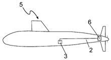
도 2 는 본 개시의 실시 형태에 따른 배의 개략 측면도이다.
도 3 은 본 발명의 실시 형태에 따른 제조 방법의 흐름도이다.1 is a schematic front view of a charging station according to an embodiment of the present disclosure.
2 is a schematic side view of a ship according to an embodiment of the present disclosure.
3 is a flowchart of a manufacturing method according to an embodiment of the present invention.
도 1 은 본 개시의 실시 형태에 따른 충전 스테이션 (1) 의 개략 정면도이고, 여기서 도관의 섹션에는 21-6-9 스테인레스 강으로 제조된 이음매 없는 튜브 (2) 가 제공된다. 액체 수소 (3) 를 위한 저장부는 튜브 (2) 를 가로 질러서 액체 수소 (3) 를 위한 저장부와 유체 연통하는 펌프 노즐 (4) 을 사용함으로써 액체 수소를 추출하는데 사용된다.1 is a schematic front view of a filling
도 2 는 본 개시의 실시 형태에 따른 배 (5), 보다 구체적으로는 잠수함의 개략 측면도이고, 여기서 도관에는 본 개시의 실시 형태에 따른 이음매 없는 튜브 (2) 가 제공된다. 액체 수소 (3) 를 위한 저장부는 튜브 (2) 를 가로 질러서 연료 전지 (6) 와 유체 연통하는 잠수함 (5) 의 바디에 배열된다. 이어서, 연료 전지 (6) 는 추진 시스템 (구현되지 않음) 에 연료를 제공하는데 사용된다.2 is a schematic side view of a
도 3 은 도 1 및 도 2 에서 도시된 적용들에서 사용되는 바와 같이 튜브 (2) 로 중공부를 성형하기 위한 제조 방법을 설명하는 흐름도이다. 제 1 단계 (100) 에서, 오스테나이트계 스테인레스 강의 용융물이 제공되고, 상기 오스테나이트계 스테인레스 강은, 중량% 로, C ≤ 0.080, 8.00 ≤ Mn ≤ 10.00, Si ≤ 1.00, P ≤ 0.030, S ≤ 0.030, 19.00 ≤ Cr ≤ 21.50, 5.50 ≤ Ni ≤ 7.50, 0.15 ≤ N ≤ 0.40, Mo ≤ 0.75, Cu ≤ 0.75, 잔부 Fe 및 정상적으로 발생하는 불순물들로 이루어진다.3 is a flow diagram illustrating a manufacturing method for forming a hollow with
제 2 단계 (101) 에서 용융물로부터 빌렛을 압출한 후, 빌렛은 단계 (102) 에서 관형 중공부로 열간 압연된다. 이어서, 중공부는 단계 (103) 에서 실온으로 냉각된다. 끝에서 두 번째 단계 (104) 에서, 중공부는 상세한 설명에 설명된 바와 같이 튜브로 냉간 펄거 밀링된다. 마지막 단계 (105) 에서, 튜브는 냉간 인발된다.After extruding the billet from the melt in the
원래 개시의 목적들을 위해, 모든 특징들은 이들 특징들이 특정 추가 특징들을 참조하여 단지 설명되었지만 본 발명의 상세한 설명, 도면들 및 청구 범위로부터 이 분야의 숙련자에게 명백하게 되고, 그리고 이런 조합들이 명시적으로 배제되지 않거나 기술적 사실들이 이런 조합들을 배제하거나 이들을 쓸모 없게 하는 한, 그 자체로 또는 여기서 개시된 다른 특징들 또는 특징들의 그룹들과 임의의 조합들로 조합될 수 있다는 점에 유의해야 한다. 특징들의 각각의 가능한 조합에 대한 포괄적이고 명시적인 설명은 단지 짧고 가독성 있는 설명을 제공하기 위해 생략된다.For the purposes of the original disclosure, all features are apparent to those skilled in the art from the detailed description, drawings and claims of the present invention, although these features have been merely described with reference to specific additional features, and such combinations are expressly excluded. It should be noted that unless or technical facts exclude these combinations or render them obsolete, they may be combined by themselves or in any combination with other features or groups of features disclosed herein. A comprehensive and explicit description of each possible combination of features is omitted merely to provide a short and readable description.
본 개시는 도면들 및 전술한 상세한 설명에서 상세하게 나타나 있지만, 이 설명은 단지 예시적인 것이고 청구 범위에 의해서 규정되는 바와 같이 보호 범위의 제한을 의도하지 않는다. 본 발명은 개시된 실시 형태들로 제한되지 않는다.Although the present disclosure is shown in detail in the drawings and the foregoing detailed description, this description is exemplary only and is not intended to limit the scope of protection as defined by the claims. The invention is not limited to the disclosed embodiments.
개시된 실시 형태들의 변형들은 도면들, 상세한 설명 및 첨부된 청구 범위로부터 이 분야의 숙련자에게 명백할 것이다. 청구 범위에서, 용어 “포함하다” 는 다른 요소들 또는 단계들을 배제하는 것이 아니고, 그리고 단수 표기는 다수를 배제하는 것이 아니다. 어떤 특징들이 상이한 청구 범위에서 청구된다는 사실만으로 이들의 조합을 배제하는 것은 아니다. 청구 범위에서 도면 번호들은 보호 받고자 하는 범위를 한정하려는 의도가 아니다.Variations of the disclosed embodiments will be apparent to those skilled in the art from the drawings, detailed description and appended claims. In the claims, the term “comprises” does not exclude other elements or steps, and the singular notation does not exclude the majority. The fact that certain features are claimed in different claims does not exclude combinations of them. Drawing numbers in the claims are not intended to limit the scope to be protected.
1 충전 스테이션
2 튜브
3 액체 수소를 위한 저장부
4 펌프 노즐
5 배
6 연료 전지
100 오스테나이트계 스테인레스 강의 용융물의 제공
101 용융물로부터 빌렛의 압출
102 관형 중공부로 빌렛의 열간 압연
103 냉각 단계
104 냉간 필거 밀링 단계
105 냉간 인발 단계1 charging station
2 tubes
3 Storage section for liquid hydrogen
4 pump nozzle
5 times
6 fuel cell
Provision of 100 austenitic stainless steel melt
101 Extrusion of billet from melt
102 Hot rolling of billet with hollow tube
103 cooling steps
104 cold pilger milling steps
105 cold drawing steps
Claims (15)
액체 수소 전달 장비,
액체 수소 수용 장비, 및
상기 액체 수소 전달 장비와 상기 액체 수소 수용 장비 사이에서 액체 수소를 안내하기 위하여 상기 액체 수소 전달 장비 및 상기 액체 수소 수용 장비와 유체 연통하는 도관을 갖고,
도관의 적어도 섹션 (section) 이, 중량% 로,
C ≤ 0.080,
8.00 ≤ Mn ≤ 10.00,
Si ≤ 1.00,
P ≤ 0.030,
S ≤ 0.030,
19.00 ≤ Cr ≤ 21.50,
5.50 ≤ Ni ≤ 7.50,
0.15 ≤ N ≤ 0.40,
Mo ≤ 0.75,
Cu ≤ 0.75,
잔부 Fe 및 불가피하게 발생하는 불순물들을 포함하는 오스테나이트계 스테인레스 강으로 제조된 이음매 없는 튜브 (2) 에 의해서 제공되는 것을 특징으로 하는, 액체 수소 전달 시스템.A liquid hydrogen delivery system,
Liquid hydrogen transfer equipment,
Liquid hydrogen receiving equipment, and
A conduit in fluid communication with the liquid hydrogen delivery equipment and the liquid hydrogen receiving equipment to guide liquid hydrogen between the liquid hydrogen delivery equipment and the liquid hydrogen receiving equipment,
At least a section of the conduit, in weight percent,
C ≤ 0.080,
8.00 ≤ Mn ≤ 10.00,
Si ≤ 1.00,
P ≤ 0.030,
S ≤ 0.030,
19.00 ≤ Cr ≤ 21.50,
5.50 ≤ Ni ≤ 7.50,
0.15 ≤ N ≤ 0.40,
Mo ≤ 0.75,
Cu ≤ 0.75,
Liquid hydrogen delivery system, characterized by being provided by a seamless tube (2) made of austenitic stainless steel containing the residual Fe and inevitable impurities.
상기 액체 수소 전달 시스템은 충전 스테이션 (1) 이고, 여기서 상기 액체 수소 전달 장비는 액체 수소를 위한 저장부 (3) 이고, 그리고 상기 액체 수소 수용 장비는 펌프 노즐 (4) 인, 액체 수소 전달 시스템.According to claim 1,
The liquid hydrogen delivery system is a filling station (1), wherein the liquid hydrogen delivery equipment is a reservoir (3) for liquid hydrogen, and the liquid hydrogen receiving equipment is a pump nozzle (4).
상기 액체 수소 전달 시스템은 차량, 항공기 또는 배 (5) 이고, 여기서 상기 액체 수소 전달 장비는 액체 수소를 위한 저장부 (3) 이고, 그리고 상기 액체 수소 수용 장비는 수소 엔진 또는 연료 전지 (6) 인, 액체 수소 전달 시스템.According to claim 1,
The liquid hydrogen delivery system is a vehicle, aircraft or ship (5), wherein the liquid hydrogen delivery equipment is a reservoir (3) for liquid hydrogen, and the liquid hydrogen receiving equipment is a hydrogen engine or fuel cell (6). , Liquid hydrogen delivery system.
상기 튜브 (2) 는,
중량% 로,
C ≤ 0.080,
8.00 ≤ Mn ≤ 10.00,
Si ≤ 1.00,
P ≤ 0.030,
S ≤ 0.030,
19.00 ≤ Cr ≤ 21.50,
5.50 ≤ Ni ≤ 7.50,
0.15 ≤ N ≤ 0.40,
Mo ≤ 0.75,
Cu ≤ 0.75,
잔부 Fe 및 불가피하게 발생하는 불순물들을 포함하는 오스테나이트계 스테인레스 강의 용융물을 제공하는 단계 (100),
상기 용융물로부터 빌렛을 압출하는 단계 (101),
관형 중공부로 상기 빌렛을 열간 성형하는 단계 (102),
상기 중공부를 냉각시키는 단계 (103), 그리고
상기 튜브 (2) 로 상기 중공부를 냉간 성형하는 단계 (104, 105) 를 포함하는 방법에 의해서 얻어지는, 액체 수소 전달 시스템.The method according to any one of claims 1 to 3,
The tube (2),
In weight percent,
C ≤ 0.080,
8.00 ≤ Mn ≤ 10.00,
Si ≤ 1.00,
P ≤ 0.030,
S ≤ 0.030,
19.00 ≤ Cr ≤ 21.50,
5.50 ≤ Ni ≤ 7.50,
0.15 ≤ N ≤ 0.40,
Mo ≤ 0.75,
Cu ≤ 0.75,
Providing (100) a melt of an austenitic stainless steel containing residual Fe and inevitable impurities.
Extruding the billet from the melt (101),
Hot forming the billet into a tubular hollow portion (102),
Cooling the hollow portion (103), and
A liquid hydrogen delivery system, obtained by a method comprising cold forming (104, 105) the hollow with the tube (2).
상기 냉간 성형하는 단계는 냉간 필거 밀링 (104) 또는 냉간 인발 (105) 인, 액체 수소 전달 시스템. The method of claim 4,
The cold forming step is cold pilger milling (104) or cold drawing (105), a liquid hydrogen delivery system.
상기 튜브 (2) 는 냉간 필거 밀링 (104) 에 의해서 냉간 성형되고, 그리고 냉간 필거 밀링 (104) 후에, 상기 튜브 (2) 는 인발 다이를 통하여 냉간 인발 (105) 되는, 액체 수소 전달 시스템. The method of claim 5,
The tube (2) is cold formed by cold pilger milling (104), and after cold pilger milling (104), the tube (2) is cold drawn (105) through a draw die, liquid hydrogen delivery system.
냉간 성형 (104, 105) 후에, 상기 튜브 (2) 는 링 오토프레타즈 (autofrettage) 또는 볼 오토프레타즈에 의해서 처리되는, 액체 수소 전달 시스템.The method of claim 5 or 6,
After cold forming (104, 105), the tube (2) is treated by a ring autopretage (autofrettage) or a ball autopretase, a liquid hydrogen delivery system.
냉간 성형 (104, 105) 후에, 상기 튜브 (2) 는 400℃ 내지 460℃ 범위의 온도에서 어닐링되고, 여기서 어닐링 동안, 상기 튜브는 제어된 분위기에서 유지되는, 액체 수소 전달 시스템.The method according to any one of claims 5 to 7,
After cold forming 104, 105, the tube 2 is annealed at a temperature in the range of 400 ° C to 460 ° C, where during the annealing, the tube is maintained in a controlled atmosphere.
상기 튜브 (2) 는 40 mm 이하의 외부 직경 및 1.32 mm 이하의 벽 두께를 갖는, 액체 수소 전달 시스템. The method according to any one of claims 1 to 8,
The tube (2) has an outer diameter of 40 mm or less and a wall thickness of 1.32 mm or less.
중량% 로,
C ≤ 0.080,
8.00 ≤ Mn ≤ 10.00,
Si ≤ 1.00,
P ≤ 0.030,
S ≤ 0.030,
19.00 ≤ Cr ≤ 21.50,
5.50 ≤ Ni ≤ 7.50,
0.15 ≤ N ≤ 0.40,
Mo ≤ 0.75,
Cu ≤ 0.75,
잔부 Fe 및 불가피하게 발생하는 불순물들을 포함하는 오스테나이트계 스테인레스 강의 용융물을 제공하는 단계 (100),
상기 용융물로부터 빌렛을 압출하는 단계 (101),
관형 중공부로 상기 빌렛을 열간 성형하는 단계 (102),
상기 중공부를 냉각시키는 단계 (103), 그리고
상기 튜브 (2) 로 상기 중공부를 냉간 성형하는 단계 (104, 105) 를 포함하는, 액체 수소 전달 시스템의 제조 방법.A method of manufacturing a liquid hydrogen delivery system, the production of a tube (2) forming a conduit of the liquid hydrogen delivery system,
In weight percent,
C ≤ 0.080,
8.00 ≤ Mn ≤ 10.00,
Si ≤ 1.00,
P ≤ 0.030,
S ≤ 0.030,
19.00 ≤ Cr ≤ 21.50,
5.50 ≤ Ni ≤ 7.50,
0.15 ≤ N ≤ 0.40,
Mo ≤ 0.75,
Cu ≤ 0.75,
Providing (100) a melt of an austenitic stainless steel containing residual Fe and inevitable impurities.
Extruding the billet from the melt (101),
Hot forming the billet into a tubular hollow portion (102),
Cooling the hollow portion (103), and
Cold forming the hollow with the tube (2) (104, 105), a method of manufacturing a liquid hydrogen delivery system.
상기 냉간 성형하는 단계는 냉간 필거 밀링 (104) 또는 냉간 인발 (105) 인, 액체 수소 전달 시스템의 제조 방법.The method of claim 11,
The cold forming step is cold pilger milling (104) or cold drawing (105), the method of manufacturing a liquid hydrogen delivery system.
상기 중공부는 냉간 필거 밀링 (104) 에 의해서 냉간 성형되고, 그리고 냉간 필거 밀링 (104) 후에, 상기 튜브 (2) 는 인발 다이를 통하여 냉간 인발 (105) 되는, 액체 수소 전달 시스템의 제조 방법. The method of claim 11 or 12,
The hollow portion is cold formed by cold pilger milling (104), and after cold pilger milling (104), the tube (2) is cold drawn (105) through a draw die, the method of manufacturing a liquid hydrogen delivery system.
냉간 성형 후에, 상기 튜브 (2) 는 링 오토프레타즈 또는 볼 오토프레타즈에 의해서 처리되는, 액체 수소 전달 시스템의 제조 방법.The method of claim 12 or 13,
After cold forming, the tube (2) is processed by a ring autopretase or a ball autopretase, a method for producing a liquid hydrogen delivery system.
냉간 핑거 밀링 (104) 후에, 상기 튜브 (2) 는 400℃ 내지 460℃ 범위의 온도에서 어닐링되고, 여기서 어닐링 동안, 상기 튜브는 제어된 분위기에서 유지되는, 액체 수소 전달 시스템의 제조 방법.The method according to any one of claims 12 to 14,
After cold finger milling 104, the tube 2 is annealed at a temperature ranging from 400 ° C to 460 ° C, where during the annealing, the tube is maintained in a controlled atmosphere.
Applications Claiming Priority (3)
| Application Number | Priority Date | Filing Date | Title |
|---|---|---|---|
| DE102017121364.3 | 2017-09-14 | ||
| DE102017121364 | 2017-09-14 | ||
| PCT/EP2018/074549 WO2019053035A1 (en) | 2017-09-14 | 2018-09-12 | A system for transmission of liquid hydrogen |
Publications (1)
| Publication Number | Publication Date |
|---|---|
| KR20200046021A true KR20200046021A (en) | 2020-05-06 |
Family
ID=63557483
Family Applications (1)
| Application Number | Title | Priority Date | Filing Date |
|---|---|---|---|
| KR1020207004415A KR20200046021A (en) | 2017-09-14 | 2018-09-12 | Liquid hydrogen delivery system |
Country Status (6)
| Country | Link |
|---|---|
| US (1) | US20200200325A1 (en) |
| EP (1) | EP3682156A1 (en) |
| JP (2) | JP2020534480A (en) |
| KR (1) | KR20200046021A (en) |
| CN (2) | CN115127019A (en) |
| WO (1) | WO2019053035A1 (en) |
Families Citing this family (1)
| Publication number | Priority date | Publication date | Assignee | Title |
|---|---|---|---|---|
| WO2021257567A1 (en) | 2020-06-15 | 2021-12-23 | Joby Aero, Inc. | High efficiency hydrogen fueled high altitude thermodynamic fuel cell system and aircraft using same |
Family Cites Families (12)
| Publication number | Priority date | Publication date | Assignee | Title |
|---|---|---|---|---|
| US3592634A (en) * | 1968-04-30 | 1971-07-13 | Armco Steel Corp | High-strength corrosion-resistant stainless steel |
| JPS62144805A (en) * | 1985-12-20 | 1987-06-29 | Sumitomo Metal Ind Ltd | Method for charging succeeding material in cold pilger rolling mill |
| US20060275168A1 (en) * | 2005-06-03 | 2006-12-07 | Ati Properties, Inc. | Austenitic stainless steel |
| US20080190214A1 (en) * | 2007-02-08 | 2008-08-14 | Pratt & Whitney Rocketdyne, Inc. | Cut-back flow straightener |
| CN101713019B (en) * | 2008-10-07 | 2011-05-04 | 上海高泰稀贵金属股份有限公司 | Method for manufacturing spaceflight high-temperature alloy GH3600 fine thin-wall seamless pipe |
| JP2010121190A (en) * | 2008-11-21 | 2010-06-03 | Nisshin Steel Co Ltd | Austenitic stainless welded pipe for high-pressure hydrogen transport, and method for producing the same |
| JP4692650B2 (en) * | 2009-02-13 | 2011-06-01 | 住友金属工業株式会社 | Seamless pipe manufacturing method |
| CN101633999B (en) * | 2009-05-26 | 2011-06-01 | 山西太钢不锈钢股份有限公司 | Austenitic stainless steel, steel tube thereof and manufacturing method thereof |
| KR20130045931A (en) * | 2010-09-29 | 2013-05-06 | 닛폰 스틸 앤드 스미킨 스테인레스 스틸 코포레이션 | Austenite high-manganese stainless steel, manufacturing method therefor, and member using said steel |
| AU2013318430A1 (en) * | 2012-09-19 | 2015-04-09 | Stephen Foster | Integrated dispensing station |
| MX2017000077A (en) * | 2014-06-27 | 2017-05-30 | Ati Properties Llc | Flowforming corrosion resistant alloy tubes and tube manufactured thereby. |
| JP6627343B2 (en) * | 2014-10-07 | 2020-01-08 | 日本製鉄株式会社 | Austenitic stainless steel and equipment for high-pressure hydrogen gas or liquid hydrogen |
-
2018
- 2018-09-12 CN CN202210581418.0A patent/CN115127019A/en active Pending
- 2018-09-12 EP EP18769165.4A patent/EP3682156A1/en active Pending
- 2018-09-12 JP JP2020507629A patent/JP2020534480A/en active Pending
- 2018-09-12 WO PCT/EP2018/074549 patent/WO2019053035A1/en unknown
- 2018-09-12 US US16/638,863 patent/US20200200325A1/en not_active Abandoned
- 2018-09-12 KR KR1020207004415A patent/KR20200046021A/en not_active Application Discontinuation
- 2018-09-12 CN CN201880052523.7A patent/CN110998171B/en active Active
-
2023
- 2023-07-18 JP JP2023116479A patent/JP2023153831A/en active Pending
Also Published As
| Publication number | Publication date |
|---|---|
| CN110998171A (en) | 2020-04-10 |
| WO2019053035A1 (en) | 2019-03-21 |
| US20200200325A1 (en) | 2020-06-25 |
| CN110998171B (en) | 2022-05-13 |
| CN115127019A (en) | 2022-09-30 |
| JP2020534480A (en) | 2020-11-26 |
| EP3682156A1 (en) | 2020-07-22 |
| JP2023153831A (en) | 2023-10-18 |
Similar Documents
| Publication | Publication Date | Title |
|---|---|---|
| CN104831120B (en) | The manufacture method of titanium alloy seamless tube | |
| EP1678335B1 (en) | Low carbon alloy steel tube having ultra high strength and excellent toughness at low temperature and method of manufacturing the same | |
| EP2007914B1 (en) | Low carbon alloy steel tube having ultra high strength and excellent toughness at low temperature and method of manufacturing the same | |
| EP2434028B1 (en) | Hollow seamless pipe for high-strength springs | |
| JP6465249B2 (en) | ERW steel pipe for high-strength thin-walled hollow stabilizer and method for manufacturing the same | |
| CN102282273B (en) | Process for production of duplex stainless steel pipe | |
| JP5979334B1 (en) | High strength welded steel pipe for airbag inflator and method for manufacturing the same | |
| EP3023507B1 (en) | Equipment line for manufacturing seamless steel pipes, and method for manufacturing high-strength stainless seamless steel pipe for oil wells | |
| EP2484793A1 (en) | Steel pipe for air bag and process for producing same | |
| EP1983065B1 (en) | Method for manufacturing bottle member for air bag inflator | |
| EP1820576B1 (en) | Production method of seamless steel pipe | |
| JP2023153831A (en) | System for transmission of liquid hydrogen | |
| CN110306120B (en) | X80 steel grade D1422mm seamless bent pipe and manufacturing method thereof | |
| WO2016111292A1 (en) | Hollow seamless steel pipe for spring | |
| US10501820B2 (en) | Method for producing a strand from stainless steel and strand made of stainless steel | |
| EP1876253B1 (en) | Stainless steel pipe for oil well excellent in enlarging characteristics | |
| EP2835439B1 (en) | Hollow seamless pipe for high-strength spring | |
| CN111118410A (en) | Thick-wall large-caliber high-steel grade pipeline pipe with thickness of 40-60 mm and manufacturing method thereof | |
| AU2020413417B2 (en) | Alloy | |
| US20200199720A1 (en) | A tube made of an austenitic stainless steel and a method for manufacturing thereof | |
| US20200200132A1 (en) | A distributor fuel rail and a method for manufacturing a distributor fuel rail | |
| CN110938784A (en) | Thick-wall large-caliber high-steel grade pipeline pipe with thickness of 40-60 mm and manufacturing method thereof | |
| Nikitin et al. | Production of seamless bimetallic pipe for the nuclear industry | |
| CN107335971A (en) | The compound spiral of carbon steel stainless steel and its manufacture method | |
| CN117083405A (en) | Fe-Ni alloy, in particular for transporting and storing liquid hydrogen |
Legal Events
| Date | Code | Title | Description |
|---|---|---|---|
| E902 | Notification of reason for refusal | ||
| E601 | Decision to refuse application |