KR20200041017A - A hand-held tool device mounted on an industrial robot that can be selectively replaced - Google Patents
A hand-held tool device mounted on an industrial robot that can be selectively replaced Download PDFInfo
- Publication number
- KR20200041017A KR20200041017A KR1020180120879A KR20180120879A KR20200041017A KR 20200041017 A KR20200041017 A KR 20200041017A KR 1020180120879 A KR1020180120879 A KR 1020180120879A KR 20180120879 A KR20180120879 A KR 20180120879A KR 20200041017 A KR20200041017 A KR 20200041017A
- Authority
- KR
- South Korea
- Prior art keywords
- fixed
- tool
- industrial robot
- main body
- working body
- Prior art date
Links
Images


Classifications
-
- B—PERFORMING OPERATIONS; TRANSPORTING
- B25—HAND TOOLS; PORTABLE POWER-DRIVEN TOOLS; MANIPULATORS
- B25J—MANIPULATORS; CHAMBERS PROVIDED WITH MANIPULATION DEVICES
- B25J15/00—Gripping heads and other end effectors
- B25J15/04—Gripping heads and other end effectors with provision for the remote detachment or exchange of the head or parts thereof
- B25J15/0408—Connections means
-
- B—PERFORMING OPERATIONS; TRANSPORTING
- B25—HAND TOOLS; PORTABLE POWER-DRIVEN TOOLS; MANIPULATORS
- B25J—MANIPULATORS; CHAMBERS PROVIDED WITH MANIPULATION DEVICES
- B25J15/00—Gripping heads and other end effectors
- B25J15/06—Gripping heads and other end effectors with vacuum or magnetic holding means
- B25J15/0616—Gripping heads and other end effectors with vacuum or magnetic holding means with vacuum
Landscapes
- Engineering & Computer Science (AREA)
- Robotics (AREA)
- Mechanical Engineering (AREA)
- Manipulator (AREA)
Abstract
Description
본 발명은 선택적인 교체가 가능한 산업용 로봇에 장착되는 수동식 툴장치에 관한 것으로, 더욱 자세하게는 산업용 로봇 팔에 장착되는 사용자가 선택적으로 손쉽게 결합 및 분리할 수 있도록 하여, 교체 등을 위한 별도의 장비를 필요로 하지 않고 용이하게 유지보수가 용이한 선택적인 교체가 가능한 산업용 로봇에 장착되는 수동식 툴장치에 관한 기술이다. The present invention relates to a manual tool device mounted on an industrial robot capable of selective replacement, and more specifically, allows a user mounted on an industrial robot arm to selectively easily combine and separate, thereby providing separate equipment for replacement, etc. It is a technology for a manual tool device mounted on an industrial robot that can be selectively replaced without need and easily maintained.
통상적으로 산업용 로봇은 다양한 산업분야에 적용되어오고 있으며, 가장 대표적으로는 프레스 등 기타 장비들을 이용하여 사출 성형된 가공대상물들을 기타 후공정으로 이동시키기 위해 별도의 작업자가 수작업을 통해 이송시켰다. In general, industrial robots have been applied to various industrial fields, and most representatively, a manual worker transports the injection-molded objects to other post-processes using other equipment such as a press.
그러나, 이러한 작업자의 수작업에 의존하게 되는 경우, 단순반복 작업으로써 작업자의 부주의로 인한 안전사고가 빈번히 발생하는 문제가 있었다. However, when relying on the manual work of such a worker, there is a problem in that a safety accident due to the carelessness of the worker frequently occurs as a simple repetitive work.
이에 근래에는 상기 작업자가 직접 생산라인에 배치되지 않고, 자동화장치(산업용 로봇 포함)를 설치하여서 해당 작업자들이 수행해오던 작업을 상기 산업용 로봇이 그 해당 작업을 수행하도록 하고 있다. Accordingly, in recent years, the operator is not directly placed on the production line, but an automation device (including an industrial robot) is installed to allow the industrial robot to perform the corresponding task performed by the worker.
우선 종래의 기술을 살펴보면, First, looking at the prior art,
등록번호 제10-1036197호(특) 다관절로봇의 아암에 교체장착되어 프레스 가공대상물을 흡착 이송시켜주는 장착툴을 고정할 수 있도록 한 다관절로봇의 장착툴 락킹구조에 있어서, 상기 아암의 길이방향으로 전후진 가능하도록 설치되는 피스톤로드를 구비하는 공압실린더; 상기 피스톤로드의 전후진 작동에 의해 연동되어 일정각도 선회할 수 있도록 일단이 상기 아암의 선단부에 힌지결합되는 한편 일측으로 연장형성되는 링크레버를 매개로 상기 피스톤로드의 끝단부와 연결되고, 타단에는 상기 장착툴의 내주면에 형성된 걸림홈에 선택적으로 끼움 결합되어 상기 아암에 장착된 장착툴의 위치를 고정해주는 걸림돌기가 형성되는 클램프부재;를 포함하여 구성된 것을 특징으로 하되, 상기 피스톤로드의 끝단부에는 외주면에 결합홈이 형성된 작동부재가 일체로 고정설치되고, 상기 결합홈에는 상기 링크레버의 끝단이 회동가능하게 삽입 결합되며, 상기 아암의 선단면에는 축 방향으로 일정길이 돌출 형성되는 적어도 하나의 가이드봉이 설치되고, 상기 장착툴의 결합면에는 상기 가이드봉이 삽입되는 삽입공이 대응되게 형성된 다관절로봇의 장착툴 락킹구조에 관한 기술이다. Registration No. 10-1036197 (Special) In the mounting tool locking structure of the articulated robot that is mounted on the arm of the articulated robot to fix the mounting tool that adsorbs and transports the object to be pressed. A pneumatic cylinder having a piston rod installed to be able to move back and forth in a direction; One end is hingedly coupled to the front end of the arm so as to be rotated at a predetermined angle by being interlocked by the forward and backward operation of the piston rod, while being connected to the end of the piston rod via a link lever that extends to one side. It characterized in that it is configured to include, but; a clamp member formed by a locking projection for fixing the position of the mounting tool mounted on the arm by being selectively fitted into the engaging groove formed on the inner circumferential surface of the mounting tool. At least one guide that is fixedly installed with an operating member having an engaging groove formed on an outer circumferential surface, and the end of the link lever is rotatably inserted into the engaging groove, and a predetermined length protruding in the axial direction on the front end surface of the arm A rod is installed, and an insertion hole into which the guide rod is inserted corresponds to a coupling surface of the mounting tool. It is the description of the mounting tool locking structure of the articulated robot provided.
상기한 종래기술은, 공압으로 작동하는 실린더의 후진에 의해 장착툴의 삽입공간을 확보하고 실린더의 전지에 의해 장착툴의 고정하도록 하는 구조로써, 별도의 공압을 공급하기 위한 구성요소가 필요함은 물론, 기계적인 구성요소들에 의해 손쉽게 상기 장착툴의 교체가 불가한 기술이다. The above-described prior art is a structure to secure the insertion space of the mounting tool by reversing the cylinder operated by pneumatic pressure, and to secure the mounting tool by the battery of the cylinder, as well as requiring a component for supplying a separate pneumatic pressure. , It is a technology that cannot be easily replaced with the mounting tool by mechanical components.
다시 말해, 어떠한 자동화 라인에 상기한 기술로 구성된 로봇을 구성할 경우, 공압실린더이 작동하여야지만 장착툴의 교체가 가능함에 따라 유지보수 시, 많은 시간이 소요될 뿐만 아니라, 별도의 공압공급을 위한 공급기를 필수적으로 구비하여야 함에 따라, 초기 설비 설치비용이 많이 소요되는 문제점을 갖고 있다. In other words, if a robot configured with the above-described technology is configured in any automation line, the pneumatic cylinder must be operated, but as the mounting tool can be replaced, it takes a lot of time for maintenance, as well as a separate supply for pneumatic supply. As it must be provided, it has a problem that an initial installation cost is high.
따라서 본 발명의 목적은, 간단한 구조로 이루어져 산업용 로봇의 아암에 장착되는 툴장치를 아암과의 결합 시, 별도의 기타 장치를 추가적으로 구성하지 않고, 툴장치를 구성하는 툴마스터 및 툴슬레이브를 작업자가 간단하게 교체할 수 있도록 하여 작업의 편리성 및 초기제작이 간편하여 경제적 효율성을 확보토록 하는 선택적인 교체가 가능한 산업용 로봇에 장착되는 수동식 툴장치를 제공함에 주안점을 두고 그 기술적 과제로 완성해낸 것이다. Therefore, the object of the present invention is made of a simple structure, when the tool device mounted on the arm of the industrial robot is combined with the arm, the operator does not additionally configure other devices, but the tool master and the tool slave constituting the tool device. The technical task was completed with the emphasis on providing a manual tool device mounted on an industrial robot that can be selectively replaced to secure economic efficiency due to convenience of operation and simple production by allowing simple replacement.
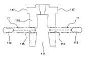
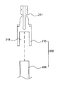
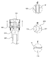
상기 목적을 달성하기 위한 기술적 사상으로서, 일측이 산업용 로봇의 아암(10)에 장착되고, 타측이 가공대상물을 흡착 이송시키도록 구성되는 산업용 로봇 툴장치에 있어서, 상기 아암(10)에 장착되되, 상기 아암(10)과 장착되는 타측에 장착툴(220)을 고정하는 고정뭉치(210)가 끼움되는 끼움홈(111)이 형성되고, 내부에 상기 끼움홈(111)측 방향으로 작동몸체(120)의 작동에 의해 밀림되는 고정돌기(113)가 형성되는 메인몸체(110)와, 상기 메인몸체(110)의 외주에 결합 구성되되 선택적으로 상기 메인몸체(110)에서 왕복운동을 하고, 내측이 상기 고정돌기(113)와 맞닿게 형성되는 밀림턱(121)이 형성되는 작동몸체(120)로 구성되는 툴마스터(100); 일측이 상기 메인몸체(110)의 끼움홈(111)에 끼워져 상기 작동몸체(120)의 작동에 따라 고정돌기(113)에 의해 고정되는 고정뭉치(210)와, 일측이 상기 끼움홈(111)에 끼워지는 고정뭉치(210)의 타측에 결합되어 흡착패드 또는 가공대상물을 흡착하는 장착툴(220)로 구성되는 툴슬레이브(200); 로 구성되는 것을 기술적 특징으로 한다.
As a technical idea for achieving the above object, one side is mounted on the
상기 메인몸체(110)는 상기 고정돌기(113)가 이동하기 위한 이동홈(115)이 상기 끼움홈(111)과 연장되게 형성되며, 상기 아암(10)과 결합되는 외주에는 상기 작동몸체(120)의 밀림턱(121)의 일측과 맞닿아 작동몸체(120)의 이동을 제한하는 걸림턱(117)이 형성되고, 상기 작동몸체(120)는 밀림턱(121)은 상기 걸림턱(117)과 맞닿는 타측은 상기 고정돌기(113)의 원활한 밀림을 위해 경사지도록 형성되며, 상기 툴슬레이브(200)의 고정뭉치(210)의 외주에는 상기 고정돌기(113)가 인입되고 고정하는 고정홈(211)이 형성되는 것을 기술적 특징으로 한다.
The
상기 이동홈(115)은 메인몸체(110)의 내부에 일정간격 이격되게 다수개로 형성되며 각각의 이동홈(115)에 고정돌기(113)가 각각 구성되며, 상기 고정홈(211)은 일정간격 이격되게 다수개 또는 상기 고정뭉치(210)의 외주에 연장되게 형성되는 것을 기술적 특징으로 한다.
The moving
상기 걸림턱(117)과 밀림턱(121)의 사이 및 상기 이동홈(115)과 고정돌기(113)의 사이에는 상기 작동몸체(120)와 고정돌기(113)가 원래의 상태로 복원될 수 있도록 탄성부재(t)가 구성되는 것을 기술적 특징으로 한다.
The
상기 아암(10)과 결착되는 메인몸체(110)의 타측에는 외주를 감싸는 작동몸체(120)의 이탈을 방지하기 위한 고정부재(300)가 구성되는 것을 기술적 특징으로 한다.
The other side of the
본 발명에 따른 선택적인 교체가 가능한 산업용 로봇에 장착되는 수동식 툴장치에 의하면, 산업분야에 사용되어 가공대상품을 흡착하는 본연의 목적을 그대로 유지함과 동시에, 툴마스터와 툴슬레이브를 별도의 기계적 장비를 구비하지 않고서도 작업자가 수동적으로 상기 툴슬레이브의 교체가 가능함에 따라, 유지보수시 편리성이 부여되고, 유,공압을 공급하여 작동하는 실린더 등을 구비하지 않게 되어 초기설치비를 절감할 수 있는 한편, 그 구조가 간단하여 제작 시 간편성을 가질 수가 있는 유용한 발명인 것이다. According to the manual tool device mounted on the industrial robot that can be selectively replaced according to the present invention, it is used in the industrial field, while maintaining the original purpose of adsorbing the products to be processed as well as separate mechanical equipment for the tool master and the tool slave As the operator can manually replace the tool slab without having to be provided, convenience is provided during maintenance, and cylinders operated by supplying oil and pneumatic pressure are not provided to reduce initial installation cost. On the other hand, it is a useful invention that can have simplicity in manufacturing due to its simple structure.
도 1은 본 발명의 바람직한 실시 예를 나타내는 정면도
도 2는 본 발명의 바람직한 실시 예를 나타내는 정단면도
도 3은 본 발명의 바람직한 실시 예를 나타내는 분해도
도 4는 본 발명의 툴마스터의 바람직한 실시 예를 나타내는 분해도
도 5는 본 발명의 툴마스터의 바람직한 실시 예를 나타내는 분해도
도 6은 본 발명의 툴마스터의 바람직한 실시 예를 나타내는 작동상태도
도 7은 본 발명의 툴슬레이브의 바람직한 실시 예를 나타내는 분해도
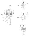
도 8은 본 발명의 바람직한 실시 예를 나타내는 사용상태도, 확대도
도 9는 본 발명의 바람직한 실시 예를 나타내는 사용상태도, 확대도
도 10은 본 발명의 바람직한 실시 예를 나타내는 사용상태도1 is a front view showing a preferred embodiment of the present invention
2 is a front sectional view showing a preferred embodiment of the present invention
3 is an exploded view showing a preferred embodiment of the present invention
Figure 4 is an exploded view showing a preferred embodiment of the tool master of the present invention
5 is an exploded view showing a preferred embodiment of the tool master of the present invention
6 is an operational state diagram showing a preferred embodiment of the tool master of the present invention
7 is an exploded view showing a preferred embodiment of the tool slave of the present invention
8 is a use state diagram showing an exemplary embodiment of the present invention, an enlarged view
9 is a use state diagram showing an exemplary embodiment of the present invention, an enlarged view
10 is a use state diagram showing a preferred embodiment of the present invention
본 발명은 산업용 로봇 팔에 장착되는 사용자가 선택적으로 손쉽게 결합 및 분리할 수 있도록 하여, 교체 등을 위한 별도의 장비를 필요로 하지 않고 용이하게 유지보수가 용이한 선택적인 교체가 가능한 산업용 로봇에 장착되는 수동식 툴장치를 제공한다. The present invention allows the user mounted on the industrial robot arm to be selectively easily combined and detached, and does not require a separate equipment for replacement and the like, and is mounted on an industrial robot that can be selectively replaced for easy maintenance. To provide a manual tool device.
이하, 첨부되는 도면과 관련하여 상기 목적을 달성하기 위한 본 발명의 바람직한 구성 및 작용에 대하여 도 1 내지 도 10을 참고로 하여 설명하면 다음과 같다. Hereinafter, a preferred configuration and operation of the present invention for achieving the above object with reference to the accompanying drawings will be described with reference to FIGS. 1 to 10 as follows.
우선 본 발명을 설명하기에 앞서 그 구성을 도 1 내지 도 5를 참고하여 설명하면, 일측이 산업용 로봇의 아암(10)에 장착되고, 타측이 가공대상물을 흡착 이송시키도록 구성되는 산업용 로봇 툴장치에 있어서, 상기 아암(10)에 장착되되, 상기 아암(10)과 장착되는 타측에 장착툴(220)을 고정하는 고정뭉치(210)가 끼움되는 끼움홈(111)이 형성되고, 내부에 상기 끼움홈(111)측 방향으로 작동몸체(120)의 작동에 의해 밀림되는 고정돌기(113)가 형성되는 메인몸체(110)와, 상기 메인몸체(110)의 외주에 결합 구성되되 선택적으로 상기 메인몸체(110)에서 왕복운동을 하고, 내측이 상기 고정돌기(113)와 맞닿게 형성되는 밀림턱(121)이 형성되는 작동몸체(120)로 구성되는 툴마스터(100); 일측이 상기 메인몸체(110)의 끼움홈(111)에 끼워져 상기 작동몸체(120)의 작동에 따라 고정돌기(113)에 의해 고정되는 고정뭉치(210)와, 일측이 상기 끼움홈(111)에 끼워지는 고정뭉치(210)의 타측에 결합되어 흡착패드 또는 가공대상물을 흡착하는 장착툴(220)로 구성되는 툴슬레이브(200); 로 구성된다.
First, prior to explaining the present invention, the configuration will be described with reference to FIGS. 1 to 5. One side is mounted on the
상기 툴마스터(100)는 도 1 내지 도 5에 도시된 바와 같이 메인몸체(110)와 작동몸체(120)로 대분 구성된다.
The
상기 메인몸체(110)는 도 3 내지 도 6에 도시된 바와 같이 하부에서 상부방향으로 일정깊이 고정뭉치(210)가 끼워지는 끼움홈(111)이 형성되고, 외측에는 상기 끼움홈(111)측 방향으로 상기 작동몸체(120)에 의해 밀림되는 고정돌기(133)가 구성된다.
3 to 6, the
상기 고정돌기(133)는 하기될 상기 고정뭉치(210)가 끼움될 시, 상기 고정뭉치(210)에 형성된 고정홈(211)에 끼워져 상기 고정뭉치(210)가 견고히 고정될 수 있도록 하기 위한 구성이다.
The fixing protrusion 133 is configured to be fitted into the
이때, 도 4에 도시된 바와 같이 상기 메인몸체(110)에는 상기 고정돌기(113)가 이동하기 위한 이동홈(115)이 상기 끼움홈(111)과 연장되게 형성되며, 상기 아암(10)과 결합되는 외주에는 상기 작동몸체(120)의 밀림턱(121) 일측과 맞닿아 작동몸체(120)의 이동을 제한하는 걸림턱(117)이 형성되고, 상기 작동몸체(120)의 밀림턱(121)은 상기 걸림턱(117)과 맞닿는 타측이 상기 고정돌기(113)의 원활한 밀림을 위해 경사지도록 형성된다.
At this time, as shown in FIG. 4, the
여기서, 도 4 또는 5에 도시된 바와 같이 상기 걸림턱(117)은 메인몸체(110)의 외주지름 보다 더 큰지름을 가지도록 형성 또는 외측보다 더 돌출되게 형성되어, 상기 작동몸체(120)의 밀림턱(121)과 맞닿아 상기 작동몸체(120)가 이동하는 방향으로 더 이상의 이동을 제한토록 하여, 상기 작동몸체(120)가 메인몸체(110)에서 이탈하는 것을 방지할 수가 있고, 상기 걸림턱(117)은 상기 메인몸체(110)의 외측에 하나 또는 다수개로 형성될 수가 있으며, 돌출테 형상으로 형성될 수가 있다.
Here, as shown in Figure 4 or 5, the
상기 작동몸체(120)는 중앙부가 관통되게 형성되어 상기 메인몸체(110)의 외주를 감싸며 구성되되, 내주의 공간이 상기 메인몸체(110)의 외주보다 더 크게 형성되고, 내측에 상기 메인몸체(110)의 고정돌기(113)를 밀림하면서도 상기 걸림턱(117)에 의해 고정될 수 있도록 하는 밀림턱(121)이 형성된다.
The working
상기 밀림턱(121)의 경우 도 5 또는 도 6에 도시된 바와 같이 실질적으로 상기 고정돌기(113)과 맞닿아 고정돌기(113)를 밀림시키는 부분에는 자연스러운 밀림이 이루어질 수 있도록 경사 또는 라운드지게 형성되어 상기 고정돌기(113)와의 접촉이 자연스러움을 유도하는 한편, 상기 고정돌기(113)의 원활한 작동을 도모할 수가 있게 되고, 상기 고정돌기(113)와 맞닿지 않는 타측에는 상기 메인몸체(110)의 걸림턱(117)의 측면과 대응되게 직선으로 형성된다.
In the case of the pushing
즉, 상기 작동몸체(120)는 도 6에 도시된 바와 같이 메인몸체(110)의 걸림턱(117) 방향으로 밀림하게 되면, 메인몸체(110)의 고정돌기(113)를 밀림하지 않게 되고, 상기 고정돌기(113)와 맞닿지 않는 작동몸체(120)의 밀림턱(121)이 상기 걸림턱(117)과 맞닿아 작동몸체(120)의 이동을 제한하게 된다. 반대로, 상기 작동몸체(120)를 메인몸체(110)의 걸림턱(117)이 형성된 반대방향으로 이동시키게 되면, 상기 작동몸체(120)의 밀림턱(121)의 경사진 부분이 자연스레 상기 고정돌기(113)를 밀림하게 되면, 상기 고정돌기(113)가 서서히 이동홈(115)을 통해 최종적으로 끼움홈(111) 측방향으로 이동하게 된다.
That is, when the working
여기서, 상기 이동홈(115)은 하나 또는 다수개로 형성될 수가 있으며, 상기 이동홈(115)의 개수에 따라 고정돌기(113)도 다수개로 형성되는 것이 바람직하다.
Here, the
한편, 도 4 내지 도 6에 도시된 바와 같이 상기 걸림턱(117)과 밀림턱(121)의 사이 및 상기 이동홈(115)과 고정돌기(113)의 사이에는 상기 작동몸체(120)와 고정돌기(113)가 원래의 상태로 복원될 수 있도록 탄성부재(t1, t2)가 구성된다.
Meanwhile, as shown in FIGS. 4 to 6, between the
도 8 내지 도9에 도시된 바와 같이 상기 탄성부재(t1, t2)는 밀림성질을 가지도록 구성되어, 상기 작동몸체(120)가 외압에 의해 걸림턱(117)측 방향으로 밀림되게 되면 고정돌기(113)가 탄성부재(t1)에 의해 밀림되고, 상기 작동몸체(120)가 탄성부재(t2)에 의해 밀림되면 재차 상기 밀림턱(121)이 고정돌기(113)를 밀림시켜서 원래의 상태로 복원되게 되는데, 이때, 상기 탄성부재(t1)보다 탄성부재(t2)가 더 강한 밀림력을 가지도록 구성되는 것이 바람직하다.
8 to 9, the elastic members (t1, t2) are configured to have a pushing property, and when the working
왜냐하면, 상기 작동몸체(120)가 걸림턱(117)측 방향으로 이동되면, 하기될 툴슬레이브(200)의 끼움 및 분리가 자유로워지는 반면에, 상기 걸림턱(117)의 반대방향으로 이동되어 고정돌기(113)를 밀림시키게 되면, 끼워진 툴슬레이브(200)를 완전히 고정시키기 때문에, 상기 툴마스터(100)와 툴슬레이브(200)가 고정된 상태로 작업이 이루어져야 하기 때문이고, 상기 작동몸체(120)의 작동은 사용자가 선택적으로 수행하기 때문이다.
Because, when the working
다시 말해, 본 발명의 끼움 및 분리구조는 종래의 유, 공압으로 작동하는 실린더에 의해 고정 및 풀림이 이루어져, 구조가 복잡하고 초기 제작 비용이 많이 발생하였던 문제점을 완전히 극복할 수 있도록 수동식으로 작업자가 직접 툴마스터(100)를 조작하여서 툴슬레이브(200)를 교체할 수가 있게 되어 유지보수의 편리성을 부여할 수가 있다.
In other words, the fitting and separating structure of the present invention is fixed and released by a conventional hydraulic and pneumatically operated cylinder, so that the worker can be manually operated to completely overcome the problem that the structure is complicated and the initial production cost is high. By directly operating the
또한, 도시하진 않았지만, 상기 메인몸체(110)의 외주에는 수직방향으로 슬라이드홀이 형성되고, 상기 슬라이드홀의 끝단에는 외주둘레를 따라 삽입테가 형성되며, 상기 작동몸체(120)의 내측에는 상기 슬라이드홀과 대응하는 슬라이부부를 형성하고, 상기 슬라이드부 끝단에는 돌출부를 형성하여서, 상기 작동몸체(120)를 밀림시키면 상기 슬라이드부가 슬라이드홀을 타며 이동하고 작동몸체(120)가 걸림턱(117)으로 완전히 밀림된 후, 상기 작동몸체(120)를 회전시키게 되면 상기 돌출부가 삽입테에 끼워져 탄성부재(t2)게 의해 원래의 상태로 복원을 방지할 수 있게 되고 작업자가 손쉽게 툴슬레이브(200)를 끼운 후, 상기 작동몸체(120)를 재차 회전시키게 되면 상기 탄성부재(t2)에 의해 원래의 상태로 복원되게 된다.
In addition, although not shown, a slide hole is formed in the vertical direction on the outer circumference of the
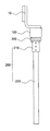
한편, 상기 툴슬레이브(200)는 도 2, 3, 7에 도시된 바와 같이 고정뭉치(210)와 장착툴(220)로 구성되는데, 상기 고정뭉치(210)는 일측이 상기 메인몸체(110)의 끼움홈(111)에 대응되는 형상으로 형성되어 상기 끼움홈(111)에 끼움되고, 외주에는 상기 고정돌기(113)가 인입되고 고정하는 고정홈(211)이 형성되어, 상기 고정돌기(113)에 의해 고정되게 된다.
On the other hand, the
이때, 상기 고정홈(211)은 일정간격 이격되게 다수개 또는 상기 고정뭉치(210)의 외주에 연장되게 형성될 수도 있으며, 본 발명에서는 외주에 연장되게 형성되는 것으로 도시하였다.
At this time, the fixing
상기 장착툴(220)의 경우 고정뭉치(210)와 결합되는 타측 끝단에는 통상의 흡착패드 또는 가공대상물을 직접 흡착할 하는 역할을 수행한다.
In the case of the mounting
또하느 도 1, 2, 3 및 도 10에 도시된 바와 같이 상기 아암(10)과 결착되는 메인몸체(110)의 타측에는 외주를 감싸는 작동몸체(120)의 이탈을 방지하기 위한 고정부재(300)가 구성되어, 상기 탄성부재(t2)에 의해 원래의 상태로 복원될 시, 메인몸체(110)의 걸림턱(117)과 동일한 역할을 수행하게 된다.
In addition, as shown in Figures 1, 2, 3 and 10, the other side of the
본 발명에 따른 선택적인 교체가 가능한 산업용 로봇에 장착되는 수동식 툴장치에 의하면, 산업분야에 사용되어 가공대상품을 흡착하는 본연의 목적을 그대로 유지함과 동시에, 툴마스터와 툴슬레이브를 별도의 기계적 장비를 구비하지 않고서도 작업자가 수동적으로 상기 툴슬레이브의 교체가 가능함에 따라, 유지보수시 편리성이 부여되고, 유,공압을 공급하여 작동하는 실린더 등을 구비하지 않게 되어 초기설치비를 절감할 수 있는 한편, 그 구조가 간단하여 제작 시 간편성을 가질 수가 있는 유용한 발명인 것이다. According to the manual tool device mounted on the industrial robot that can be selectively replaced according to the present invention, it is used in the industrial field, while maintaining the original purpose of adsorbing the products to be processed as well as separate mechanical equipment for the tool master and the tool slave As the operator can manually replace the tool slab without having to be provided, convenience is provided during maintenance, and cylinders operated by supplying oil and pneumatic pressure are not provided to reduce initial installation cost. On the other hand, it is a useful invention that can have simplicity in manufacturing due to its simple structure.
100 : 툴마스터
110 : 메인몸체
111 : 끼움홈
113 : 고정돌기
115 : 이동홈
117 : 걸림턱
120 : 작동몸체
121 : 밀림턱
200 : 툴슬레이브
210 : 고정뭉치
211 : 고정홈
213 : 결합홈
220 : 장착툴
300 : 고정부재 100: tool master
110: main body 111: fitting groove 113: fixed projection
115: moving groove 117: jam
120: working body 121: jungle jaw
200: tool slave
210: fixed bundle 211: fixed groove 213: engaging groove
220: mounting tool
300: fixing member
Claims (5)
상기 아암(10)에 장착되되, 상기 아암(10)과 장착되는 타측에 장착툴(220)을 고정하는 고정뭉치(210)가 끼움되는 끼움홈(111)이 형성되고, 내부에 상기 끼움홈(111)측 방향으로 작동몸체(120)의 작동에 의해 밀림되는 고정돌기(113)가 형성되는 메인몸체(110)와, 상기 메인몸체(110)의 외주에 결합 구성되되 선택적으로 상기 메인몸체(110)에서 왕복운동을 하고, 내측이 상기 고정돌기(113)와 맞닿게 형성되는 밀림턱(121)이 형성되는 작동몸체(120)로 구성되는 툴마스터(100);
일측이 상기 메인몸체(110)의 끼움홈(111)에 끼워져 상기 작동몸체(120)의 작동에 따라 고정돌기(113)에 의해 고정되는 고정뭉치(210)와, 일측이 상기 끼움홈(111)에 끼워지는 고정뭉치(210)의 타측에 결합되어 흡착패드 또는 가공대상물을 흡착하는 장착툴(220)로 구성되는 툴슬레이브(200); 로 구성되는 것을 특징으로 하는 선택적인 교체가 가능한 산업용 로봇에 장착되는 수동식 툴장치.
In the industrial robot tool device, one side is mounted on the arm 10 of the industrial robot, the other side is configured to adsorb and transport the object to be processed,
Mounted on the arm 10, a fitting groove 111 into which a fixed bundle 210 for fixing the mounting tool 220 is fitted is formed on the other side of the arm 10, and the fitting groove ( 111) is configured to be coupled to the outer circumference of the main body 110, and the main body 110 is formed with a fixed projection 113 is pushed by the operation of the working body 120 in the lateral direction, but optionally the main body 110 ), The tool master 100 consisting of a working body 120 in which a reciprocating motion is formed and a pushing jaw 121 is formed in which the inside comes into contact with the fixing protrusion 113;
One side is fitted into the fitting groove 111 of the main body 110 and fixed bundle 210 fixed by a fixing protrusion 113 according to the operation of the working body 120, and one side is the fitting groove 111 A tool slave 200 that is coupled to the other side of the fixed bundle 210 to be fitted to the suction pad or a mounting tool 220 for adsorbing the object to be processed; It is composed of a manual tool device mounted on an industrial robot that can be selectively replaced.
상기 메인몸체(110)는 상기 고정돌기(113)가 이동하기 위한 이동홈(115)이 상기 끼움홈(111)과 연장되게 형성되며,
상기 아암(10)과 결합되는 외주에는 상기 작동몸체(120)의 밀림턱(121)의 일측과 맞닿아 작동몸체(120)의 이동을 제한하는 걸림턱(117)이 형성되고,
상기 작동몸체(120)는 밀림턱(121)은 상기 걸림턱(117)과 맞닿는 타측은 상기 고정돌기(113)의 원활한 밀림을 위해 경사지도록 형성되며,
상기 툴슬레이브(200)의 고정뭉치(210)의 외주에는 상기 고정돌기(113)가 인입되고 고정하는 고정홈(211)이 형성되는 것을 특징으로 하는 선택적인 교체가 가능한 산업용 로봇에 장착되는 수동식 툴장치.
According to claim 1,
The main body 110 is formed so that the moving groove 115 for the fixing protrusion 113 to move is extended to the fitting groove 111,
A locking jaw 117 is formed on an outer circumference that is combined with the arm 10 to limit the movement of the working body 120 in contact with one side of the pushing jaw 121 of the working body 120,
The working body 120 is formed so that the pushing jaw 121 is inclined for the smooth pushing of the fixing protrusion 113 on the other side contacting the locking jaw 117,
On the outer periphery of the fixed bundle 210 of the tool slave 200, a manual tool mounted on an optional replaceable industrial robot, characterized in that a fixed groove 211 into which the fixed protrusion 113 is inserted and fixed is formed. Device.
상기 이동홈(115)은 메인몸체(110)의 내부에 일정간격 이격되게 다수개로 형성되며 각각의 이동홈(115)에 고정돌기(113)가 각각 구성되며,
상기 고정홈(211)은 일정간격 이격되게 다수개 또는 상기 고정뭉치(210)의 외주에 연장되게 형성되는 것을 하는 선택적인 교체가 가능한 산업용 로봇에 장착되는 수동식 툴장치.
According to claim 2,
The moving groove 115 is formed in a plurality of spaced apart at regular intervals inside the main body 110, each of the moving groove 115, fixed projections 113 are respectively configured,
The fixing groove (211) is a manual tool device mounted on a selective replaceable industrial robot that is formed to extend on the outer circumference of the fixed bundle 210 or a plurality of spaced apart at regular intervals.
상기 걸림턱(117)과 밀림턱(121)의 사이 및 상기 이동홈(115)과 고정돌기(113)의 사이에는 상기 작동몸체(120)와 고정돌기(113)가 원래의 상태로 복원될 수 있도록 탄성부재(t)가 구성되는 것을 특징으로 하는 선택적인 교체가 가능한 산업용 로봇에 장착되는 수동식 툴장치.
According to claim 2,
The working body 120 and the fixing protrusion 113 may be restored to the original state between the locking jaw 117 and the pushing jaw 121 and between the moving groove 115 and the fixing protrusion 113. So that the elastic member (t) is configured to be equipped with a manual tool device mounted on an industrial robot that can be selectively replaced.
상기 아암(10)과 결착되는 메인몸체(110)의 타측에는 외주를 감싸는 작동몸체(120)의 이탈을 방지하기 위한 고정부재(300)가 구성되는 것을 특징으로 하는 선택적인 교체가 가능한 산업용 로봇에 장착되는 수동식 툴장치.
According to claim 1,
On the other side of the main body 110 that is attached to the arm 10, a fixed member 300 for preventing the separation of the working body 120 surrounding the outer circumference is configured to an industrial robot that can be selectively replaced. Manual tool device mounted.
Priority Applications (1)
| Application Number | Priority Date | Filing Date | Title |
|---|---|---|---|
| KR1020180120879A KR102157422B1 (en) | 2018-10-11 | 2018-10-11 | A hand-held tool device mounted on an industrial robot that can be selectively replaced |
Applications Claiming Priority (1)
| Application Number | Priority Date | Filing Date | Title |
|---|---|---|---|
| KR1020180120879A KR102157422B1 (en) | 2018-10-11 | 2018-10-11 | A hand-held tool device mounted on an industrial robot that can be selectively replaced |
Publications (2)
| Publication Number | Publication Date |
|---|---|
| KR20200041017A true KR20200041017A (en) | 2020-04-21 |
| KR102157422B1 KR102157422B1 (en) | 2020-09-17 |
Family
ID=70456345
Family Applications (1)
| Application Number | Title | Priority Date | Filing Date |
|---|---|---|---|
| KR1020180120879A KR102157422B1 (en) | 2018-10-11 | 2018-10-11 | A hand-held tool device mounted on an industrial robot that can be selectively replaced |
Country Status (1)
| Country | Link |
|---|---|
| KR (1) | KR102157422B1 (en) |
Citations (6)
| Publication number | Priority date | Publication date | Assignee | Title |
|---|---|---|---|---|
| JPH0775906A (en) * | 1993-09-09 | 1995-03-20 | Mishima Kosan Co Ltd | Automatic tool changer |
| JPH0811075A (en) * | 1994-06-29 | 1996-01-16 | Olympus Optical Co Ltd | Tool adapter mounting mechanism of robot hand |
| KR101036197B1 (en) * | 2010-11-08 | 2011-05-23 | 주식회사 월드이엔지 | A tool locking structure for articulated robot |
| KR101566624B1 (en) * | 2014-06-30 | 2015-11-06 | 강남균 | Coupling device for gripper in transfer robot |
| KR20170052784A (en) * | 2015-11-04 | 2017-05-15 | 주식회사 새한산업 | Aparatus for automatically replacing gripper |
| KR20190142722A (en) * | 2018-06-18 | 2019-12-27 | 에펙토 그룹 에스.피.에이. | Tool changer device for a robotic arm |
-
2018
- 2018-10-11 KR KR1020180120879A patent/KR102157422B1/en active IP Right Grant
Patent Citations (6)
| Publication number | Priority date | Publication date | Assignee | Title |
|---|---|---|---|---|
| JPH0775906A (en) * | 1993-09-09 | 1995-03-20 | Mishima Kosan Co Ltd | Automatic tool changer |
| JPH0811075A (en) * | 1994-06-29 | 1996-01-16 | Olympus Optical Co Ltd | Tool adapter mounting mechanism of robot hand |
| KR101036197B1 (en) * | 2010-11-08 | 2011-05-23 | 주식회사 월드이엔지 | A tool locking structure for articulated robot |
| KR101566624B1 (en) * | 2014-06-30 | 2015-11-06 | 강남균 | Coupling device for gripper in transfer robot |
| KR20170052784A (en) * | 2015-11-04 | 2017-05-15 | 주식회사 새한산업 | Aparatus for automatically replacing gripper |
| KR20190142722A (en) * | 2018-06-18 | 2019-12-27 | 에펙토 그룹 에스.피.에이. | Tool changer device for a robotic arm |
Also Published As
| Publication number | Publication date |
|---|---|
| KR102157422B1 (en) | 2020-09-17 |
Similar Documents
| Publication | Publication Date | Title |
|---|---|---|
| KR101922590B1 (en) | Clamp apparatus | |
| US9266242B2 (en) | Gripper | |
| TW201618911A (en) | End effector, industrial robot, and operating method thereof | |
| US8307544B2 (en) | Coaxial cable connector tool | |
| CN105186218A (en) | Power line connection locking device for super-path prevention building machinery | |
| US20200156263A1 (en) | Gripping device | |
| US10011021B2 (en) | Gripping jaw safety device with tongue and groove for HRC | |
| KR20200041017A (en) | A hand-held tool device mounted on an industrial robot that can be selectively replaced | |
| CN103465200A (en) | Clamping device | |
| US20210138664A1 (en) | Tool adapter for manipulating commercial tools with a robot hand | |
| KR102470950B1 (en) | Gripper for Robot | |
| US4512072A (en) | Apparatus for installing poultry feather picking fingers | |
| KR102185161B1 (en) | Combine manual oil-hydraulic vise | |
| CN203510003U (en) | Clamping device | |
| KR101346839B1 (en) | Clamp | |
| KR101716095B1 (en) | Pin terminal presser | |
| US9408427B2 (en) | Snap installation tool adaptor | |
| JP5592916B2 (en) | Work gripping device | |
| JP7422351B2 (en) | Sleeve compression device and sleeve compression method | |
| US20160016221A1 (en) | Matrix for making clinch-type joints between sheet-formed members and an apparatus including such a matrix | |
| JPH0448902Y2 (en) | ||
| EP1366832B1 (en) | Tool coupling device, particularly for press machines | |
| KR102164787B1 (en) | Fixing device for robot arm | |
| KR101377199B1 (en) | Device for releasing ball joint | |
| DE502007001912D1 (en) | Battery operated electric hand tool |
Legal Events
| Date | Code | Title | Description |
|---|---|---|---|
| E902 | Notification of reason for refusal | ||
| E701 | Decision to grant or registration of patent right |