KR20200033897A - Method and device for adjustable glass ribbon heat transfer - Google Patents
Method and device for adjustable glass ribbon heat transfer Download PDFInfo
- Publication number
- KR20200033897A KR20200033897A KR1020207004689A KR20207004689A KR20200033897A KR 20200033897 A KR20200033897 A KR 20200033897A KR 1020207004689 A KR1020207004689 A KR 1020207004689A KR 20207004689 A KR20207004689 A KR 20207004689A KR 20200033897 A KR20200033897 A KR 20200033897A
- Authority
- KR
- South Korea
- Prior art keywords
- glass
- heat transfer
- modular cartridge
- sidewall
- glass ribbon
- Prior art date
Links
Images


Classifications
-
- C—CHEMISTRY; METALLURGY
- C03—GLASS; MINERAL OR SLAG WOOL
- C03B—MANUFACTURE, SHAPING, OR SUPPLEMENTARY PROCESSES
- C03B17/00—Forming molten glass by flowing-out, pushing-out, extruding or drawing downwardly or laterally from forming slits or by overflowing over lips
- C03B17/06—Forming glass sheets
- C03B17/067—Forming glass sheets combined with thermal conditioning of the sheets
-
- C—CHEMISTRY; METALLURGY
- C03—GLASS; MINERAL OR SLAG WOOL
- C03B—MANUFACTURE, SHAPING, OR SUPPLEMENTARY PROCESSES
- C03B17/00—Forming molten glass by flowing-out, pushing-out, extruding or drawing downwardly or laterally from forming slits or by overflowing over lips
- C03B17/06—Forming glass sheets
- C03B17/064—Forming glass sheets by the overflow downdraw fusion process; Isopipes therefor
-
- C—CHEMISTRY; METALLURGY
- C03—GLASS; MINERAL OR SLAG WOOL
- C03B—MANUFACTURE, SHAPING, OR SUPPLEMENTARY PROCESSES
- C03B25/00—Annealing glass products
- C03B25/04—Annealing glass products in a continuous way
- C03B25/10—Annealing glass products in a continuous way with vertical displacement of the glass products
- C03B25/12—Annealing glass products in a continuous way with vertical displacement of the glass products of glass sheets
Abstract
유리 물품을 제조하는 방법 및 장치는 제1 측벽 및 제2 측벽을 갖는 하우징을 통해 유리 리본을 유동시키는 단계를 포함한다. 이 장치는 제1 측벽 및 제2 측벽 중 적어도 하나에 제거 가능하게 위치되는 모듈형 카트리지를 포함하고, 모듈형 카트리지는 적어도 하나의 열전달 메커니즘, 및 상기 적어도 하나의 열전달 메커니즘과 유리 리본 사이에서 연장되는 제거 가능한 벽 구성요소를 포함한다.A method and apparatus for manufacturing a glass article includes flowing a glass ribbon through a housing having first and second sidewalls. The device includes a modular cartridge removably positioned on at least one of the first sidewall and the second sidewall, the modular cartridge extending between at least one heat transfer mechanism, and the at least one heat transfer mechanism and the glass ribbon Includes removable wall components.
Description
본 출원은 2017년 7월 21일에 출원된 미국 가출원 제62/535,374호의 35 U.S.C. § 119 하의 우선권의 이익을 청구하고, 그 내용은 본원의 근거가 되며 전체가 참조로 본원에 통합된다.This application is filed on July 21, 2017, US Provisional Application No. 62 / 535,374, 35 U.S.C. Claim the benefit of priority under § 119, the content of which is the basis of the present application and is incorporated herein by reference in its entirety.
본 개시내용은 대체로 유리 물품을 제조하는 방법 및 장치에 관한 것으로, 더 구체적으로는 유리 물품의 제조 시에 조절 가능한 유리 리본 열전달을 제공하는 방법 및 장치에 관한 것이다.The present disclosure relates generally to a method and apparatus for manufacturing a glass article, and more particularly to a method and apparatus for providing adjustable glass ribbon heat transfer in the manufacture of a glass article.
텔레비전 및 휴대용 디바이스, 예컨대 전화 및 태블릿을 포함하는 디스플레이 애플리케이션을 위한 유리 시트와 같은 유리 물품의 생산 시에, 유리 물품은 하우징을 통해 연속적으로 유동하는 유리 리본으로부터 생산될 수 있다. 하우징은 유리 리본과 처리 설비, 예컨대 가열 및 냉각 설비 사이의 물리적 분리를 제공하는 상부 벽 섹션을 포함할 수 있다. 이러한 상부 벽 섹션은 이러한 설비를 보호하는 물리적 장벽으로서 작용할 수 있을 뿐만 아니라, 또한 유리 리본에 의해 경험되는 열 구배를 평활화하는 열적 효과를 제공할 수도 있다. 이러한 열적 효과는 두께 균일성 및 표면 편평도 또는 파형과 같은 특정 유리 특성에 영향을 미치는 것으로 여겨진다.In the production of glass articles such as glass sheets for display applications including televisions and portable devices, such as phones and tablets, the glass articles can be produced from glass ribbons that flow continuously through the housing. The housing can include a top wall section that provides physical separation between the glass ribbon and a processing facility, such as a heating and cooling facility. This upper wall section can not only act as a physical barrier to protect these installations, but also provide a thermal effect to smooth the thermal gradient experienced by the glass ribbon. It is believed that these thermal effects affect certain glass properties such as thickness uniformity and surface flatness or corrugation.
그러나, 유리 리본과 처리 설비, 예컨대 냉각 설비 사이의 물리적 장벽은 해당 설비의 열 제거 능력을 감소시킬 수 있다. 이러한 열 제거는 낮은 비열용량 및/또는 복사율을 갖는 유리, 높은 점도 및/또는 비교적 저온 리본 온도를 갖는 유리에 대해, 상승된 유리 유속에서 점점 더 중요하다. 또한, 유리 유속, 비열용량, 복사율 및 점도의 차이는 유리 리본과 처리 설비, 예컨대 가열 및 냉각 설비 사이의 열전달에 대해 상이한 최적의 조건을 필요로 할 수 있다. 이러한 차이를 고려하기 위해 기존의 상부 벽 섹션 및 관련된 처리 설비를 재구성 또는 개장하는 것은 상당한 비용 및 공정 휴지 기간을 수반할 수 있다. 따라서, 상당한 비용 및 공정 휴지 기간 없이 이러한 차이를 조정 가능하게 고려할 수 있는 상부 벽 섹션에 대한 필요성이 존재한다.However, the physical barrier between the glass ribbon and the treatment plant, such as a cooling plant, can reduce the heat removal capability of the plant. This heat removal is increasingly important at elevated glass flow rates for glass with low specific heat capacity and / or emissivity, glass with high viscosity and / or relatively low temperature ribbon temperature. In addition, differences in glass flow rate, specific heat capacity, emissivity and viscosity may require different optimal conditions for the heat transfer between the glass ribbon and the processing equipment, such as heating and cooling equipment. Reconstruction or retrofitting of existing top wall sections and associated treatment facilities to account for these differences can involve significant cost and process downtime. Accordingly, there is a need for a top wall section that can variably account for these differences without significant cost and process downtime.
본원에 개시된 실시예는 유리 물품을 제조하는 장치를 포함한다. 장치는 제1 측벽 및 제2 측벽을 포함하는 하우징을 포함한다. 하우징은 길이방향 및 폭방향으로 연장되는 대향하는 제1 및 제2 주 표면을 갖는 유리 리본을 적어도 부분적으로 둘러싸도록 구성된다. 제1 및 제2 측벽은 유리 리본의 대향하는 제1 및 제2 주 표면의 적어도 일부를 따라 길이방향 및 폭방향으로 연장되도록 구성된다. 장치는 또한 제1 및 제2 측벽 중 적어도 하나에 제거 가능하게 위치되는 모듈형 카트리지를 포함한다. 모듈형 카트리지는 적어도 하나의 열전달 메커니즘, 및 상기 적어도 하나의 열전달 메커니즘과 유리 리본 사이에서 연장되도록 구성된 제거 가능한 벽 구성요소를 포함한다. 유리 리본과 상기 적어도 하나의 열전달 메커니즘 사이의 형상 계수(view factor)는 제거 가능한 벽 구성요소가 존재하는 경우보다 제거 가능한 벽 구성요소가 존재하지 않는 경우에 더 크다.Embodiments disclosed herein include an apparatus for manufacturing a glass article. The device includes a housing including a first sidewall and a second sidewall. The housing is configured to at least partially surround a glass ribbon having opposing first and second major surfaces extending in the longitudinal and transverse directions. The first and second sidewalls are configured to extend longitudinally and transversely along at least a portion of the opposing first and second major surfaces of the glass ribbon. The device also includes a modular cartridge removably positioned on at least one of the first and second sidewalls. The modular cartridge includes at least one heat transfer mechanism, and a removable wall component configured to extend between the at least one heat transfer mechanism and a glass ribbon. The view factor between the glass ribbon and the at least one heat transfer mechanism is greater when no removable wall component is present than when the removable wall component is present.
본원에 개시된 실시예는 또한 유리 물품을 제조하는 방법을 포함한다. 이 방법은 길이방향 및 폭방향으로 연장되는 대향하는 제1 및 제2 주 표면을 갖는 유리 리본을 제1 측벽 및 제2 측벽을 포함하는 하우징을 통해 유동시키는 단계를 포함한다. 제1 및 제2 측벽은 유리 리본의 대향하는 제1 및 제2 주 표면의 적어도 일부를 따라 길이방향 및 폭방향으로 연장된다. 모듈형 카트리지는 제1 및 제2 측벽 중 적어도 하나에 제거 가능하게 위치된다. 모듈형 카트리지는 적어도 하나의 열전달 메커니즘, 및 상기 적어도 하나의 열전달 메커니즘과 유리 리본 사이에서 연장되는 제거 가능한 벽 구성요소를 포함한다. 유리 리본과 상기 적어도 하나의 열전달 메커니즘 사이의 형상 계수는 제거 가능한 벽 구성요소가 존재하는 경우보다 제거 가능한 벽 구성요소가 존재하지 않는 경우에 더 크다.Embodiments disclosed herein also include methods of making glass articles. The method includes flowing glass ribbons having opposing first and second major surfaces extending in the longitudinal and transverse directions through a housing comprising first and second sidewalls. The first and second sidewalls extend longitudinally and transversely along at least a portion of the opposing first and second major surfaces of the glass ribbon. The modular cartridge is removably positioned on at least one of the first and second sidewalls. The modular cartridge includes at least one heat transfer mechanism, and a removable wall component extending between the at least one heat transfer mechanism and a glass ribbon. The shape factor between the glass ribbon and the at least one heat transfer mechanism is greater when no removable wall component is present than when the removable wall component is present.
본원에 개시된 실시예의 추가적인 특징 및 이점은 하기 상세한 설명에 제시되어 있으며, 이는 부분적으로 그 설명으로부터 관련 기술분야의 통상의 기술자에게 쉽게 명백하거나, 또는 하기 상세한 설명, 청구범위뿐만 아니라 첨부 도면을 포함하는 본원에 설명된 바와 같은 개시된 실시예를 실시함으로써 인식될 것이다.Additional features and advantages of the embodiments disclosed herein are set forth in the detailed description, which in part is readily apparent to those skilled in the art from that description, or which includes the following detailed description, claims, as well as the accompanying drawings. It will be appreciated by practicing the disclosed embodiments as described herein.
상기 일반적인 설명 및 하기 상세한 설명 모두는 청구된 실시예의 성질과 특성을 이해하기 위한 개관 또는 체계를 제공하도록 의도된 실시예를 제시한다는 것을 이해해야 한다. 첨부 도면은 추가적인 이해를 제공하기 위해 포함되고, 본 명세서의 일부분 내로 통합되어 이를 구성한다. 도면은 본 개시내용의 다양한 실시예를 도시하고, 설명과 함께 실시예의 원리 및 작동을 설명하는 역할을 한다.It should be understood that both the above general description and the following detailed description provide examples intended to provide an overview or framework for understanding the nature and properties of the claimed embodiments. The accompanying drawings are included to provide additional understanding, and are incorporated into and constituted as part of the specification. The drawings illustrate various embodiments of the present disclosure, and together with the description serve to explain the principles and operation of the embodiments.
도 1은 예시적인 용융 하향 인발 유리 제조 장치 및 공정의 개략도이다.
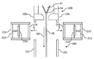
도 2는 장치의 제1 및 제2 측벽에 제거 가능하게 위치되는 모듈형 카트리지를 포함하는 유리 리본 성형 장치 및 공정의 단부 절결 개략도이다.
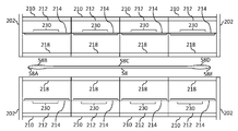
도 3은 도 2의 유리 리본 성형 장치 및 공정의 상부 절결 개략도이다.
도 4는 냉각 메커니즘이 장치로부터 제거된, 도 2의 유리 리본 성형 장치 및 공정의 상부 절결 개략도이다.
도 5는 모듈형 카트리지가 장치로부터 제거된, 도 4의 유리 리본 성형 장치 및 공정의 단부 절결 개략도이다.
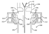
도 6은 제거 가능한 벽 구성요소가 존재하지 않는, 도 2의 유리 리본 성형 장치 및 공정의 단부 절결 개략도이다.
도 7은 모듈형 카트리지가 장치로부터 제거된, 도 6의 유리 리본 성형 장치 및 공정의 단부 절결 개략도이다.
도 8은 유리 리본 성형 장치의 지지 프레임 상에 활주식으로 위치된 모듈형 카트리지의 측면 절결 개략도이다.
도 9는 모듈형 카트리지 상에 활주식으로 위치된 제거 가능한 벽 구성요소의 단부 절결 개략도이다.1 is a schematic diagram of an exemplary melt down drawn glass manufacturing apparatus and process.
2 is an end cutaway schematic view of a glass ribbon forming apparatus and process including a modular cartridge removably positioned on the first and second sidewalls of the apparatus.
3 is a schematic top cut-away view of the glass ribbon forming apparatus and process of FIG. 2;
4 is a top cutaway schematic view of the glass ribbon forming apparatus and process of FIG. 2 with the cooling mechanism removed from the device.
5 is an end cutaway schematic view of the glass ribbon forming apparatus and process of FIG. 4 with the modular cartridge removed from the apparatus.
6 is a schematic end cutaway view of the glass ribbon forming apparatus and process of FIG. 2, with no removable wall components present.
7 is an end cutaway schematic view of the glass ribbon forming apparatus and process of FIG. 6 with the modular cartridge removed from the apparatus.
8 is a schematic side cut-away view of a modular cartridge slidably positioned on a support frame of a glass ribbon forming apparatus.
9 is a schematic end cutaway view of a removable wall component slidably positioned on a modular cartridge.
이제, 그 예가 첨부 도면에 도시되어 있는, 본 개시내용의 바람직한 본 실시예를 상세히 참조할 것이다. 가능하다면, 동일하거나 유사한 부분을 지칭하기 위해 도면 전체에 걸쳐 동일한 참조 부호가 사용될 것이다. 그러나, 본 개시내용은 많은 상이한 형태로 구현될 수 있으며 본원에 제시된 실시예로 한정되는 것으로 해석되어서는 안 된다.Reference will now be made in detail to this preferred embodiment of the present disclosure, the example of which is shown in the accompanying drawings. Where possible, the same reference numerals will be used throughout the drawings to refer to the same or similar parts. However, the present disclosure can be implemented in many different forms and should not be construed as limited to the examples presented herein.
범위는 본원에서 "약" 하나의 특정한 값부터 그리고/또는 "약" 또 다른 특정한 값까지로 표현될 수 있다. 이러한 범위가 표현되는 경우, 또 다른 실시예는 하나의 특정한 값부터 그리고/또는 다른 특정한 값까지를 포함한다. 마찬가지로, 값이, 예를 들어, 선행하는 "약"의 사용에 의해 근사치로서 표현되는 경우, 특정한 값이 또 다른 실시예를 형성함을 이해해야 한다. 각각의 범위의 종점은 다른 종점에 관하여, 그리고 다른 종점에 독립적으로 모두 중요함을 추가로 이해해야 한다.Ranges can be expressed herein as from “about” one particular value and / or to “about” another particular value. When such a range is expressed, another embodiment includes from one specific value and / or to another specific value. Likewise, it should be understood that if a value is expressed as an approximation, eg, by the use of a preceding “about”, a particular value forms another embodiment. It should be further understood that the endpoints of each range are important with respect to the other endpoints and independently of the other endpoints.
본원에서 사용될 때, 방향과 관련된 용어 - 예를 들어, 위, 아래, 우측, 좌측, 전방, 후방, 상부, 저부 - 는 단지 도시된 바와 같은 도면을 참조하여 수행되고, 절대 배향을 암시하도록 의도되지 않는다.As used herein, terms related to orientation-for example, top, bottom, right, left, front, rear, top, bottom-are only performed with reference to the drawings as shown, and are not intended to imply absolute orientation. Does not.
달리 명시되지 않는 한, 본원에 제시된 임의의 방법은, 그 단계가 구체적인 순서로 수행될 것을 요구하는 바로 해석되거나 또는 임의의 장치에 있어서 구체적인 배향이 요구되는 것으로 의도된 것이 결코 아니다. 따라서, 방법 청구항이 실제로 그 단계가 후속되는 것으로 순서를 기재하지 않는 경우, 또는 임의의 장치 청구항이 개별 구성요소에 대한 순서나 배향을 실제로 기재하지 않는 경우, 또는 단계가 구체적인 순서로 제한된다는 것이 청구항이나 상세한 설명에 구체적으로 달리 선언되어 있지 않은 경우, 또는 장치의 구성요소에 대한 구체적인 순서나 배향이 기재되지 않는 경우, 어떠한 관점에서도 순서 또는 배향이 추론되는 것으로 의도된 것이 결코 아니다. 이는, 하기를 포함하여, 해석에 있어 임의의 가능한 비-명시적 기초(non-express basis)의 경우에도 적용된다: 단계의 배열, 작동의 흐름, 구성요소의 순서, 또는 구성요소의 배향에 관한 로직 문제; 문법적 구성이나 구두법에서 파생된 평범한 의미 및; 명세서에 설명된 실시예의 수 또는 유형.Unless otherwise specified, any method presented herein is never to be interpreted as requiring that the steps be performed in a specific order or intended to require specific orientation in any device. Thus, it is claimed that a method claim does not actually describe the order as the step being followed, or that any device claim does not actually describe the order or orientation for an individual component, or that the steps are limited to a specific order. However, the order or orientation is never intended to be inferred from any point of view unless specifically stated otherwise in the detailed description, or if no specific order or orientation of components of the device is described. This also applies to any possible non-express basis for interpretation, including: arrangement of steps, flow of operation, order of components, or orientation of components. Logic problems; Ordinary meaning derived from grammatical composition or punctuation; Number or types of embodiments described in the specification.
본원에서 사용될 때, 단수 형태는 문맥이 명확하게 달리 지시하지 않는 한 복수의 지시대상을 포함한다. 따라서, 예를 들어, 문맥이 명확하게 달리 나타내지 않는 한, "하나의" 구성요소에 대한 언급은 2개 이상의 그러한 구성요소를 갖는 양태를 포함한다.As used herein, the singular form includes a plurality of indications unless the context clearly dictates otherwise. Thus, for example, unless the context clearly indicates otherwise, reference to a “one” component includes aspects having two or more such components.
본원에서 사용될 때, "가열 메커니즘"이라는 용어는 이러한 가열 메커니즘이 존재하지 않는 조건에 비해 유리 리본의 적어도 일부로부터의 감소된 열전달을 제공하는 메커니즘을 지칭한다. 감소된 열전달은 전도, 대류 및 복사 중 적어도 하나를 통해 발생할 수 있다. 예를 들어, 가열 메커니즘은 이러한 가열 메커니즘이 존재하지 않는 조건에 비해 유리 리본의 적어도 일부와 그 환경 사이에 감소된 온도 차를 제공할 수 있다.As used herein, the term “heating mechanism” refers to a mechanism that provides reduced heat transfer from at least a portion of the glass ribbon compared to conditions where such a heating mechanism is not present. Reduced heat transfer can occur through at least one of conduction, convection and radiation. For example, the heating mechanism can provide a reduced temperature difference between at least a portion of the glass ribbon and its environment compared to conditions where such a heating mechanism is not present.
본원에서 사용될 때, "냉각 메커니즘"이라는 용어는 이러한 냉각 메커니즘이 존재하지 않는 조건에 비해 유리 리본의 적어도 일부로부터 증가된 열전달을 제공하는 메커니즘을 지칭한다. 증가된 열전달은 전도, 대류 및 복사 중 적어도 하나를 통해 발생할 수 있다. 예를 들어, 냉각 메커니즘은 이러한 냉각 메커니즘이 존재하지 않는 조건에 비해 유리 리본의 적어도 일부와 그 환경 사이에 증가된 온도 차를 제공할 수 있다.As used herein, the term “cooling mechanism” refers to a mechanism that provides increased heat transfer from at least a portion of the glass ribbon compared to conditions where such a cooling mechanism is not present. Increased heat transfer can occur through at least one of conduction, convection and radiation. For example, a cooling mechanism can provide an increased temperature difference between at least a portion of the glass ribbon and its environment compared to conditions where such a cooling mechanism is not present.
본원에서 사용될 때, "열전달 메커니즘"이라는 용어는 가열 메커니즘 및 냉각 메커니즘 중 적어도 하나를 지칭한다.As used herein, the term "heat transfer mechanism" refers to at least one of a heating mechanism and a cooling mechanism.
본원에서 사용될 때, "형상 계수"라는 용어는, 소정의 표면을 떠나고 다른 표면에 충돌하는 복사선의 비율, 예컨대 유리 리본을 떠나고 열전달 메커니즘에 충돌하는 복사선의 비율을 지칭한다.As used herein, the term “shape factor” refers to the proportion of radiation leaving one surface and impinging on another surface, such as the rate of radiation leaving the glass ribbon and impinging the heat transfer mechanism.
본원에서 사용될 때, "하우징"이라는 용어는 그 안에서 유리 리본이 성형되는 외피를 의미하고, 유리 리본이 하우징을 통해 이동함에 따라, 이는 대체로 비교적 더 높은 온도에서 비교적 더 낮은 온도로 냉각된다. 본원에 개시된 실시예는 유리 리본이 대체로 수직 방향으로 하우징을 통해 아래로 유동하는 용융 하향 인발 공정을 참조하여 설명되었지만, 이러한 실시예는 또한 플로트 공정, 슬롯 인발 공정, 상향 인발 공정, 및 프레스 롤링 공정과 같은 다른 유리 성형 공정에 적용 가능하다는 것을 이해해야 하고, 유리 리본은 대체로 수직 방향 또는 대체로 수평 방향과 같은 다양한 방향으로 하우징을 통해 유동할 수 있다.As used herein, the term “housing” refers to an outer shell within which a glass ribbon is molded, and as the glass ribbon moves through the housing, it is generally cooled from a relatively higher temperature to a relatively lower temperature. Although the embodiments disclosed herein have been described with reference to a melt down draw process in which the glass ribbon flows down through the housing in a generally vertical direction, these embodiments are also described as float processes, slot draw processes, up draw processes, and press rolling processes. It should be understood that it is applicable to other glass forming processes, such as, and the glass ribbon may flow through the housing in various directions, such as generally vertical direction or generally horizontal direction.
도 1에는 예시적인 유리 제조 장치(10)가 도시되어 있다. 일부 예에서, 유리 제조 장치(10)는, 용융 용기(14)를 포함할 수 있는 유리 용융로(12)를 포함할 수 있다. 용융 용기(14)에 추가하여, 유리 용융로(12)는 원재료를 가열하고 원재료를 용융 유리로 변환하는 가열 요소(예를 들면, 연소 버너 또는 전극)와 같은 하나 이상의 추가 구성요소를 선택적으로 포함할 수 있다. 다른 예에서, 유리 용융로(12)는 용융 용기의 부근으로부터 손실되는 열을 감소시키는 열 관리 디바이스(예를 들면, 절연 구성요소)를 포함할 수 있다. 또 다른 예에서, 유리 용융로(12)는 원재료의 유리 용융물로의 용융을 용이하게 하는 전자 디바이스 및/또는 전기 기계 디바이스를 포함할 수 있다. 여전히 추가적으로, 유리 용융로(12)는 지지 구조물(예를 들면, 지지 섀시, 지지 부재 등) 또는 다른 구성요소를 포함할 수 있다.1, an exemplary
유리 용융 용기(14)는 전형적으로 내화성 세라믹 재료, 예를 들어 알루미나 또는 지르코니아를 포함하는 내화성 세라믹 재료와 같은 내화성 재료로 구성된다. 일부 예에서, 유리 용융 용기(14)는 내화성 세라믹 벽돌로 구성될 수 있다. 유리 용융 용기(14)의 구체적인 실시예가 더 상세하게 후술될 것이다.The
일부 예에서, 유리 용융로는 유리 기판, 예를 들어 연속 길이의 유리 리본을 제조하기 위한 유리 제조 장치의 구성요소로서 통합될 수 있다. 일부 예에서, 본 개시내용의 유리 용융로는 슬롯 인발 장치, 플로트 배스(float bath) 장치, 용융 공정과 같은 하향 인발 장치, 상향 인발 장치, 프레스 롤링 장치, 튜브 인발 장치 또는 본원에 개시된 양태로부터 이익을 얻을 수 있는 임의의 다른 유리 제조 장치를 포함하는 유리 제조 장치의 구성요소로서 통합될 수 있다. 예로서, 도 1은 개별 유리 시트로의 후속 처리를 위해 유리 리본을 용융 인발하기 위한 용융 하향 인발 유리 제조 장치(10)의 구성요소인 유리 용융로(12)를 개략적으로 도시한다.In some examples, the glass melting furnace can be incorporated as a component of a glass manufacturing apparatus for manufacturing a glass substrate, such as a continuous length of glass ribbon. In some examples, the glass melting furnaces of the present disclosure benefit from slot draw devices, float bath devices, down draw devices such as melting processes, up draw devices, press rolling devices, tube draw devices, or aspects disclosed herein. It can be incorporated as a component of a glass making apparatus, including any other glass making apparatus obtainable. As an example, FIG. 1 schematically shows a
유리 제조 장치(10)[예를 들면, 용융 하향 인발 장치(10)]는 유리 용융 용기(14)에 대해 상류에 위치된 상류 유리 제조 장치(16)를 선택적으로 포함할 수 있다. 일부 예에서, 상류 유리 제조 장치(16)의 일부 또는 전체는 유리 용융로(12)의 부분으로서 통합될 수 있다.The glass making apparatus 10 (eg, melt down drawing apparatus 10) may optionally include an upstream glass making apparatus 16 positioned upstream relative to the
도시된 예에 도시된 바와 같이, 상류 유리 제조 장치(16)는 저장 통(18), 원재료 전달 디바이스(20), 및 원재료 전달 디바이스에 연결된 모터(22)를 포함할 수 있다. 저장 통(18)은, 화살표(26)에 의해 나타낸 바와 같이, 유리 용융로(12)의 용융 용기(14) 내로 공급될 수 있는 소정량의 원재료(24)를 저장하도록 구성될 수 있다. 원재료(24)는 전형적으로 하나 이상의 유리 형성 금속 산화물 및 하나 이상의 개질제를 포함한다. 일부 예에서, 원재료 전달 디바이스(20)는 모터(22)에 의해 동력을 공급받아 원재료 전달 디바이스(20)가 저장 통(18)으로부터 용융 용기(14)로 미리 결정된 양의 원재료(24)를 전달하도록 할 수 있다. 다른 예에서, 모터(22)는 용융 용기(14)로부터 하류에서 감지되는 용융 유리의 레벨에 기초하여 제어된 속도로 원재료(24)를 도입하도록 원재료 전달 디바이스(20)에 동력을 공급할 수 있다. 용융 용기(14) 내의 원재료(24)는 그 후에 가열되어 용융 유리(28)를 형성할 수 있다.As shown in the illustrated example, the upstream glass making apparatus 16 may include a
또한, 유리 제조 장치(10)는 유리 용융로(12)에 대해 하류에 위치된 하류 유리 제조 장치(30)를 선택적으로 포함할 수 있다. 일부 예에서, 하류 유리 제조 장치(30)의 일부는 유리 용융로(12)의 부분으로서 통합될 수 있다. 일부 예에서, 후술되는 제1 연결 도관(32), 또는 하류 유리 제조 장치(30)의 다른 부분은 유리 용융로(12)의 부분으로서 통합될 수 있다. 제1 연결 도관(32)을 포함하여, 하류 유리 제조 장치의 요소는 귀금속으로 형성될 수 있다. 적합한 귀금속은 백금, 이리듐, 로듐, 오스뮴, 루테늄 및 팔라듐으로 이루어진 금속 군으로부터 선택된 백금족 금속, 또는 그 합금을 포함한다. 예를 들어, 유리 제조 장치의 하류 구성요소는 약 70 내지 약 90 무게%의 백금 및 약 10 무게% 내지 약 30 무게%의 로듐을 포함하는 백금-로듐 합금으로 형성될 수 있다. 그러나, 다른 적합한 금속은 몰리브덴, 팔라듐, 레늄, 탄탈럼, 티타늄, 텅스텐 및 그들의 합금을 포함할 수 있다.Further, the
하류 유리 제조 장치(30)는, 용융 용기(14)로부터 하류에 위치되고 상술된 제1 연결 도관(32)에 의해 용융 용기(14)에 결합되는 제1 컨디셔닝(즉, 처리) 용기(conditioning vessel), 예컨대 청징 용기(34)를 포함할 수 있다. 일부 예에서, 용융 유리(28)는 제1 연결 도관(32)에 의해 용융 용기(14)로부터 청징 용기(34)로 중력 공급될 수 있다. 예를 들어, 중력은 용융 유리(28)가 용융 용기(14)로부터 청징 용기(34)까지 제1 연결 도관(32)의 내부 경로를 통과하게 할 수 있다. 그러나, 다른 컨디셔닝 용기가 용융 용기(14)의 하류, 예를 들어 용융 용기(14)와 청징 용기(34) 사이에 위치될 수 있음을 이해해야 한다. 일부 실시예에서, 컨디셔닝 용기가 용융 용기와 청징 용기 사이에 채용될 수 있으며, 1차 용융 용기로부터의 용융 유리는 추가로 가열되어 용융 공정을 계속하거나, 또는 청징 용기에 진입하기 전에, 용융 용기 내의 용융 유리의 온도보다 더 낮은 온도로 냉각된다.The downstream
기포는 다양한 기술에 의해 청징 용기(34) 내의 용융 유리(28)로부터 제거될 수 있다. 예를 들어, 원재료(24)는, 가열될 때 화학적 환원 반응을 겪고 산소를 방출하는 산화주석과 같은, 다가 화합물(즉, 청징제)을 포함할 수 있다. 다른 적합한 청징제는 비제한적으로 비소, 안티모니, 철 및 세륨을 포함한다. 청징 용기(34)는 용융 용기 온도 보다 더 높은 온도까지 가열되고, 그로 인해 용융 유리 및 청징제를 가열한다. 청징제(들)의 온도-유도 화학적 환원에 의해 생성된 산소 기포는 청징 용기 내의 용융 유리를 통해 상승하고, 용융로 내에서 생성된 용융 유리 내의 기체가 청징제에 의해 생성된 산소 기포 내로 확산 또는 응집될 수 있다. 이어서, 확대된 기포는 청징 용기 내의 용융 유리의 자유 표면까지 상승할 수 있고, 그 후에 청징 용기로부터 분출될 수 있다. 산소 기포는 추가로 청징 용기 내의 용융 유리의 기계적 혼합을 유도할 수 있다.Bubbles can be removed from the
하류 유리 제조 장치(30)는 용융 유리를 혼합하기 위한 혼합 용기(36)와 같은 또 다른 컨디셔닝 용기를 추가로 포함할 수 있다. 혼합 용기(36)는 청징 용기(34)로부터 하류에 위치될 수 있다. 혼합 용기(36)는 균질한 유리 용융 조성물을 제공하는 데 사용될 수 있고, 그로 인해 그렇지 않으면 청징 용기를 빠져나가는 청징된 용융 유리 내에 존재할 수 있는 화학적 또는 열적 불균질성의 코드를 감소시키는 데 사용될 수 있다. 도시된 바와 같이, 청징 용기(34)는 제2 연결 도관(38)에 의해 혼합 용기(36)에 결합될 수 있다. 일부 예에서, 용융 유리(28)는 제2 연결 도관(38)에 의해 청징 용기(34)로부터 혼합 용기(36)로 중력 공급될 수 있다. 예를 들어, 중력은 용융 유리(28)가 청징 용기(34)로부터 혼합 용기(36)까지 제2 연결 도관(38)의 내부 경로를 통과하게 할 수 있다. 혼합 용기(36)가 청징 용기(34)의 하류에 도시되어 있지만, 혼합 용기(36)는 청징 용기(34)로부터 상류에 위치될 수 있음을 유의하여야 한다. 일부 실시예에서, 하류 유리 제조 장치(30)는 다수의 혼합 용기, 예를 들어 청징 용기(34)로부터 상류의 혼합 용기, 및 청징 용기(34)로부터 하류의 혼합 용기를 포함할 수 있다. 이러한 다수의 혼합 용기는 동일한 설계의 것일 수 있거나, 상이한 설계의 것일 수 있다.The downstream
하류 유리 제조 장치(30)는 혼합 용기(36)로부터 하류에 위치될 수 있는 전달 용기(40)와 같은 또 다른 컨디셔닝 용기를 추가로 포함할 수 있다. 전달 용기(40)는 하류 성형 디바이스 내로 공급될 용융 유리(28)를 컨디셔닝할 수 있다. 예를 들어, 전달 용기(40)는, 용융 유리(28)의 일정한 유동을 조정하고 그리고/또는 출구 도관(44)에 의해 일정한 유동을 성형체(42)에 제공하기 위한 축적기 및/또는 유동 제어기로서 작용할 수 있다. 도시된 바와 같이, 혼합 용기(36)는 제3 연결 도관(46)에 의해 전달 용기(40)에 결합될 수 있다. 일부 예에서, 용융 유리(28)는 제3 연결 도관(46)에 의해 혼합 용기(36)로부터 전달 용기(40)로 중력 공급될 수 있다. 예를 들어, 중력은 혼합 용기(36)로부터 전달 용기(40)로 제3 연결 도관(46)의 내부 경로를 통해 용융 유리(28)를 구동할 수 있다.The downstream
하류 유리 제조 장치(30)는 성형 장치(48)를 추가로 포함할 수 있고, 성형 장치는 상술된 성형체(42) 및 유입구 도관(50)을 포함한다. 출구 도관(44)은 전달 용기(40)로부터 성형 장치(48)의 유입구 도관(50)으로 용융 유리(28)를 전달하도록 위치될 수 있다. 예에서, 예를 들어, 출구 도관(44)은 유입구 도관(50)의 내부 표면 내에 안착되어 그로부터 이격될 수 있고, 그로 인해 출구 도관(44)의 외부 표면과 유입구 도관(50)의 내부 표면 사이에 위치된 용융 유리의 자유 표면을 제공할 수 있다. 용융 하향 인발 유리 제조 장치 내의 성형체(42)는 성형체의 상위 표면 내에 위치된 홈통(52), 및 성형체의 저부 에지(56)를 따라 인발 방향으로 수렴하는 수렴 성형 표면(54)을 포함할 수 있다. 전달 용기(40), 출구 도관(44) 및 유입구 도관(50)을 통해 성형체 홈통에 전달된 용융 유리는 홈통의 측벽을 과류하고 수렴 성형 표면(54)을 따라 용융 유리의 개별 유동으로서 하강한다. 용융 유리의 개별 유동은 저부 에지(56) 아래에서 그리고 그를 따라 합류되어 단일 유리 리본(58)을 생성하고, 단일 유리 리본은 유리가 냉각되고 유리의 점도가 증가함에 따라 유리 리본의 치수를 제어하기 위해 예컨대 중력, 에지 롤(72) 및 견인 롤(82)에 의해 유리 리본에 인장을 인가함으로써 저부 에지(56)로부터 인발 또는 유동 방향(60)으로 인발된다. 따라서, 유리 리본(58)은 점탄성 전이를 겪고, 유리 리본(58)에 안정적 치수 특성을 부여하는 기계적 성질을 취득한다. 유리 리본(58)은, 일부 실시예에서, 유리 리본의 탄성 영역 내에서 유리 분리 장치(100)에 의해 개별 유리 시트(62)로 분리될 수 있다. 이어서, 로봇(64)이 파지 도구(65)를 이용하여 개별 유리 시트(62)를 컨베이어 시스템으로 전달할 수 있고, 여기서 개별 유리 시트가 추가적으로 처리될 수 있다.The downstream
도 2는 전기 저항 요소(214) 및 절연 패키지(212)를 포함하는 가열 메커니즘(230)을 포함하는 모듈형 카트리지(210)를 포함하는 유리 리본 성형 장치 및 공정의 단부 절결 개략도이다. 구체적으로, 도 2에 도시된 실시예에서, 유리 리본(58)은 성형체(42)의 저부 에지(56) 아래에서 그리고 하우징(200)의 제1 및 제2 측벽(202) 사이에서 길이방향으로 인발 또는 유동 방향(60)으로 유동한다. 하우징(200)은 분리 부재(206)에 의해 성형체 외피(208)로부터 대체로 분리될 수 있고, 유리 리본(58)의 인발 또는 유동 방향(60)을 참조하면, 하우징(200)은 성형체 외피(208)에 비해 하류에 있다.FIG. 2 is a schematic end cutaway view of a glass ribbon forming apparatus and process comprising a
모듈형 카트리지(210)는 또한 가열 메커니즘(230)과 유리 리본(58) 사이에서 연장되는 제거 가능한 벽 구성요소(218)를 포함한다. 도 2에 도시된 바와 같이, 일 실시예에서, 제거 가능한 벽 구성요소(218)는 제1 및 제2 측벽(202)과 동일 평면 상에 있고, 이 평면은 유리 리본(58)의 유동 방향(60)과 대체로 평행하다.The
각각의 제거 가능한 벽 구성요소(218)는 제1 및 제2 측벽(202)을 구성하는 재료 또는 재료들과 동일하거나 상이한 재료 또는 재료들을 포함할 수 있다. 특정한 예시적 실시예에서, 각각의 제거 가능한 벽 구성요소(218) 및 제1 및 제2 측벽(202)의 각각은, 약 750℃ 초과의 온도와 같은 이러한 온도에서 높은 기계적 무결성을 유지하면서, 상승된 온도에서 비교적 높은 열전도도를 갖는 재료를 포함한다. 제거 가능한 벽 구성요소(218) 및 제1 및 제2 측벽(202)을 위한 예시적인 재료는, 다양한 등급의 탄화규소, 알루미나 내화물질, 지르콘-기반 내화물질, 티타늄-기반 합금강, 및 니켈-기반 합금강 중 적어도 하나를 포함할 수 있다. 제거 가능한 벽 구성요소(218)는 또한 Cetek로부터 입수 가능한 M700 블랙 코팅과 같은 높은 복사율 코팅으로 코팅될 수 있다.Each
도 2에 도시된 실시예는 전기 저항 요소(214) 및 절연 패키지(212)를 포함하는 가열 메커니즘(230)을 포함하는 모듈형 카트리지(210)를 도시하지만, 본원에 개시된 실시예는, 예를 들어 유도 가열, 화염 가열, 플라즈마 가열, 진동 가열, 레이저 가열, 및 마이크로파 가열을 포함하는 가열 메커니즘과 같은 다른 유형의 가열 메커니즘을 포함한다는 것을 이해해야 한다.Although the embodiment shown in FIG. 2 shows a
모듈형 카트리지(210)는 또한, 폭방향으로 유리 리본(58)에 실질적으로 평행하게 연장되고 적합한 전기 공급부에 연결되는 바아 또는 막대-형상의 전기 저항 가열 요소를 포함하는 가열 메커니즘과 같은 가열 메커니즘을 적어도 하나 포함하거나 그 주위로 연장될 수 있다. 바아 또는 막대-형상의 가열 요소는, 예를 들어, 탄화규소, 몰리브덴 디실리사이드, 니크롬, 백금 합금, 및 관련 기술분야의 통상의 기술자에게 공지된 다양한 상업적인 가열 조성물을 포함할 수 있다. 상업적으로 입수 가능한 저항 가열 막대는 I Squared R Element Co.로부터 입수 가능한 탄화규소 Starbars® 및 Sandvik으로부터 입수 가능한 Globars™를 포함한다.The
도 2에 도시된 바와 같이, 모듈형 카트리지(210)는, 그를 통해 유동하는 냉각 유체를 갖는 도관(216)을 포함하는 냉각 메커니즘(228) 주위로 연장된다. 도관(216)은 가열 메커니즘(230)과 유리 리본(58) 사이에서 연장된다. 또한, 제거 가능한 벽 구성요소(218)는 도관(216)과 유리 리본(58) 사이에서 연장된다.As shown in FIG. 2, the
특정한 예시적 실시예에서, 도관(216)을 통해 유동하는 냉각 유체는 물과 같은 액체를 포함할 수 있다. 특정한 예시적 실시예에서, 도관(216)을 통해 유동하는 냉각 유체는 공기와 같은 기체를 포함할 수 있다. 도 2, 도 6 및 도 7은 대체로 원형 단면을 갖는 도관(216)을 도시하고 있지만, 본원에 개시된 실시예는 도관이 타원형 또는 다각형과 같은 다른 단면 기하구조를 갖는 것을 포함한다는 것을 이해해야 한다. 더욱이, 본원에 개시된 실시예는, 유리 리본(58)으로부터 그 폭방향으로 상이한 양의 열전달이 요구되는 경우와 같이, 유리 리본(58)으로부터의 원하는 열전달의 양에 따라, 각각의 도관(216)의 직경 또는 단면적이 대략적으로 동일하거나 그 종방향 길이를 따라 변하는 것을 포함한다는 것을 이해해야 한다. 또한, 본원에 개시된 실시예는 각각의 도관(216)의 종방향 길이가 동일하거나 상이하고, 그 폭방향으로 유리 리본(58)을 가로질러 전체적으로 연장되거나 그렇지 않을 수 있는 것을 포함한다.In certain example embodiments, the cooling fluid flowing through
도관(210)을 위한 예시적인 재료는 300 시리즈 스테인리스강과 같은 스테인리스강을 포함하는 다양한 합금강을 포함하여, 상승된 온도에서 양호한 기계적 특성 및 산화 특성을 소유하는 것을 포함한다.Exemplary materials for
또한, 본원에 개시된 실시예는, 유리 리본(58)과 도관(216) 사이의 복사 열전달에 영향을 미치도록 높은 복사율 코팅이 각각의 도관(216)의 외부 표면의 적어도 일부에 퇴적되는 것을 포함하는데, 유리 리본(58)으로부터의 원하는 열전달 양에 따라 동일하거나 상이한 코팅이 각각의 도관(216)의 외부 표면 상에 그 종방향 길이를 따라 퇴적될 수 있다. 예시적인 고 복사율 코팅은 상승된 온도에서 안정적이어야 하고 스테인리스강과 같은 재료에 양호한 부착성을 가져야 한다. 일 예시적인 고 복사율 코팅은 Cetek으로부터 입수 가능한 M700 블랙 코팅이다.In addition, embodiments disclosed herein include that a high emissivity coating is deposited on at least a portion of the outer surface of each
각각의 도관(216)은 그 종방향 길이의 적어도 일부를 따라 연장되는 하나 이상의 유체 채널을 포함할 수 있는데, 냉각 유체가 제1 단부에서 도관 내로 도입되고 제1 채널을 따라서 도관의 종방향 길이의 적어도 일부를 따라 유동하고, 이어서 제1 채널을 원주방향으로 둘러싸거나 제1 채널에 의해 원주방향으로 둘러싸이는 제2 채널을 따라 도관의 제1 단부로 다시 유동하는 경우와 같이, 적어도 하나의 채널이 적어도 하나의 다른 채널을 원주방향으로 둘러싸는 실시예가 포함된다. 도관(216)의 이러한 그리고 추가적인 예시적 실시예는, 예를 들어, WO2006/044929A1에 설명되어 있으며, 그 전체 개시내용은 본원에 참조로 통합되어 있다.Each
도 2는 유리 리본(58)의 각각의 측면 상에서 3개의 도관(216) 주위로 연장되는 모듈형 카트리지(210)를 도시하지만, 본원에 개시된 실시예는 모듈형 카트리지(210)가 임의의 개수의 도관 및/또는 임의의 다른 유형의 냉각 메커니즘(228) 주위로 연장되는 것을 포함할 수 있다는 것을 이해해야 한다. 본원에 개시된 실시예는 모듈형 카트리지(210)가 적어도 하나의 가열 메커니즘 주위로 연장되는 것을 또한 포함한다.2 shows a
또한, 모듈형 카트리지(210)는 도 2에 도시된 바와 같이 냉각 메커니즘(228) 주위로 연장될 수 있지만, 본원에 개시된 실시예는 모듈형 카트리지가 적어도 하나의 냉각 메커니즘(228)을 포함하는 것을 포함한다. 예를 들어, 모듈형 카트리지는 대류 냉각 메커니즘 주위로 연장되거나 그를 포함할 수 있는데, 예컨대 이는 WO2014/193780A1에 개시된 바와 같은 복수의 진공 포트를 포함하는 진공 냉각 메커니즘이고, 그 전체 개시내용은 본원에 참조로 통합되어 있다.In addition, the
모듈형 카트리지(210)는 또한 유동 방향(60)에 실질적으로 직교하여 연장되는 종방향 축을 각각 포함하는 복수의 냉각 튜브를 포함하는 냉각 메커니즘(228) 주위로 연장되거나 그를 포함할 수 있다. 각각의 냉각 튜브는, 제거 가능한 벽 구성요소(218)에 인접하게 위치될 수 있고 냉각 튜브의 개방 단부로부터 배기되어 제거 가능한 벽 구성요소(218)의 배면에 충돌하는 공기와 같은 냉각 유체가 공급될 수 있는 개방 단부를 포함한다. 냉각 튜브로의 유체의 공급은 개별적으로 제어될 수 있어서, 유리 리본(58)의 폭방향으로의 온도 분포가 제어되거나 변할 수 있도록 한다. 예시적인 냉각 튜브는 미국 특허 제3,682,609호 및 제3,723,082호에 설명된 것을 포함하고, 그 전체 개시내용은 본원에 참조로 통합되어 있다.The
모듈형 카트리지(210)는 또한, 유리 리본(58)으로부터 복사 열전달과 같은 열전달을 향상시키기 위한 목적으로 증발냉각 효과를 이용하는 냉각 메커니즘(228) 주위로 연장되거나 또는 그를 포함할 수 있다. 이러한 냉각 메커니즘은, 예를 들어, 물과 같은 작동 액체를 수용하도록 구성된 액체 저장부, 및 액체 저장부 내에 수용된 작동 액체와 열접촉하게 배치되도록 구성된 열전달 요소를 포함하는 증발기 유닛을 포함할 수 있는데, 열전달 요소는 유리 리본(58)으로부터의 복사열을 수용하고 액체 저장부 내에 수용된 작동 액체로 열을 전달하여, 그로 인해 소정의 작동 액체를 증기로 변환함으로써 유리 리본(58)을 냉각시키도록 구성될 수 있다. 증발냉각 효과를 이용하는 냉각 메커니즘의 이러한 그리고 추가적인 예시적 실시예는, 예를 들어 US2016/0046518A1에 개시되어 있으며, 그 전체 개시내용은 본원에 참조로 통합되어 있다.The
본원에 개시된 실시예와 함께 사용될 수 있는 다른 냉각 메커니즘은, 예를 들어, WO2012/174353A2에 설명된 것과 같은, 유리 리본(58)의 유동 방향(60)에 횡방향으로 연장되는 냉각 축을 따라 위치되는 복수의 냉각 코일을 포함하는 것을 포함하며, 그 전체 개시내용은 본원에 참조로 통합되어 있다. 이러한 냉각 코일은 도관(216)과 조합하여 그리고/또는 그를 대체하여 사용될 수 있다.Other cooling mechanisms that can be used with the embodiments disclosed herein are located along a cooling axis extending transversely to the
도 3은 도 2의 유리 리본 성형 장치 및 공정의 상부 절결 개략도를 도시하는데, 유리 리본(58)은 폭방향으로 제1 단부(58A), 제1 비드 영역(58B), 중심 영역(58C), 제2 비드 영역(58D), 및 제2 단부(58E)를 갖는 것으로 도시되어 있다. 도 3은 유리 리본(58)의 대향 주 표면을 따라 폭방향으로 연장되는 4개의 모듈형 카트리지(210)를 도시하지만, 본원에 개시된 실시예는 이에 한정되는 것이 아니고, 폭방향으로 연장되는 임의의 개수의 모듈형 카트리지를 포함할 수 있다는 것을 이해해야 한다.FIG. 3 shows a schematic top cut-away view of the glass ribbon forming apparatus and process of FIG. 2, wherein the
도 4는 도 2의 유리 리본 성형 장치 및 공정의 상부 절결 개략도를 도시하는데, 그를 통해 유동하는 냉각 유체를 갖는 도관(216)을 포함하는 냉각 메커니즘(228)이 장치로부터 제거되어 있다. 예를 들어, 도관(216)은 측벽(202) 중 하나를 통해 그 축방향을 따라 제거될 수 있는데, 각각의 측벽(202)은 도관(216)이 그를 통해 연장되는 개구를 포함한다.FIG. 4 shows a schematic top cut-away view of the glass ribbon forming apparatus and process of FIG. 2, wherein a
도 5는 도 4의 유리 리본 성형 장치 및 공정의 단부 절결 개략도를 도시하는데, 도관(216)을 포함하는 냉각 메커니즘(228)의 제거에 후속하여 모듈형 카트리지(210)가 장치로부터 제거되어 있다. 도 5에서, 제거 가능한 벽 구성요소(218), 및 전기 저항 요소(214) 및 절연 패키지(212)를 포함하는 가열 메커니즘(230)을 포함하는 모듈형 카트리지(212)는, 도 5에 도시된 바와 같이 유리 리본 성형 장치의 단부로부터 볼 때, 유리 리본(58)의 유동 방향(60)에 대략적으로 수직인 화살표(A 및 B)로 도시된 대향 방향으로 장치로부터 제거된다.FIG. 5 shows a schematic view of the end cut of the glass ribbon forming apparatus and process of FIG. 4, following removal of the
도 5에 도시된 바와 같이, 모듈형 카트리지(210)의 장치로부터의 제거에 후속하여, 이러한 모듈형 카트리지는 교체 카트리지로 교체될 수 있다. 이러한 교체 카트리지는 교체되는 모듈형 카트리지와 동일하거나 상이한 모듈형 카트리지를 포함할 수 있다. 예를 들어, 교체 카트리지는 제거 가능한 벽 구성요소(218)가 제거되어 있는 모듈형 카트리지(210)를 포함할 수 있다. 교체 카트리지는 장치로부터 제거된 모듈형 카트리지 내의 열전달 메커니즘보다 유리 리본으로부터 더 많거나 적은 양의 열전달을 실현하는 적어도 하나의 열전달 메커니즘을 포함하는 모듈형 카트리지를 또한 포함할 수 있다.As shown in FIG. 5, following removal of the
도 6은 도 2의 유리 리본 성형 장치 및 공정의 단부 절결 개략도를 도시하는데, 제거 가능한 벽 구성요소(218)(도 2 내지 도 5에 도시됨)가 존재하지 않는다. 제거 가능한 벽 구성요소(218)가 모듈형 카트리지(210)에 존재하지 않는 경우, 모듈형 카트리지(210)가 그 주위로 연장되거나 그를 포함하는 임의의 열전달 메커니즘과 유리 리본(58) 사이의 형상 계수는, 제거 가능한 벽 구성요소(218)가 존재하는 경우보다 더 크다. 예를 들어, 도 6에서, 제거 가능한 벽 구성요소(218)(도 2 내지 도 5에 도시됨)가 존재하지 않는 경우, 전기 저항 요소(214) 및 절연 패키지(212)를 포함하는 가열 메커니즘(230)과 유리 리본(58) 사이의 형상 계수, 및 냉각 유체가 그를 통해 유동하는 도관(216)을 포함하는 냉각 메커니즘(228)과 유리 리본(58) 사이의 형상 계수는, 제거 가능한 벽 구성요소(218)가 존재하는 경우보다 더 크다.FIG. 6 shows a schematic view of the end cut of the glass ribbon forming apparatus and process of FIG. 2, wherein there is no removable wall component 218 (shown in FIGS. 2-5). If no
도 7은 도 6의 유리 리본 성형 장치 및 공정의 단부 절결 개략도를 도시하는데, 모듈형 카트리지(210)가 장치로부터 제거되어 있다. 도관(216)을 포함하는 냉각 메커니즘(228)이 장치로부터 제거된 도 5와 대조적으로, 제거 가능한 벽 구성요소(218)가 존재하지 않는 도 7에서는, 모듈형 카트리지(210)가 제거될 때 도관(216)이 장치 내에 존재하도록 유지된다. 도 5에서와 같이, 전기 저항 요소(214) 및 절연 패키지(212)를 포함하는 가열 메커니즘(230)을 포함하는 모듈형 카트리지(212)는, 도 7에 도시된 바와 같이 유리 리본 성형 장치의 단부로부터 볼 때, 유리 리본(58)의 유동 방향(60)에 대략적으로 수직인 화살표(A 및 B)로 도시된 대향 방향으로 장치로부터 제거된다.FIG. 7 shows a schematic view of the end cut of the glass ribbon forming apparatus and process of FIG. 6 with the
도 8은 유리 리본 성형 장치의 지지 프레임(220) 상에 활주식으로 위치됨으로써 제거 가능하게 위치되는 제거 가능한 벽 구성요소(218)를 포함하는 모듈형 카트리지(210)의 측면 절결 개략도를 도시한다. 도 8에 도시된 바와 같이, 지지 프레임(220)은, 모듈형 카트리지(210)를 유리 리본의 폭방향에서 미리 결정된 설정 위치에 위치되게 하는 한편, 안내 구성부(222)의 종방향 길이를 따라 리본으로부터 멀어지는 방향[예컨대, 도 5 및 도 7의 화살표(A 및 B)에 의해 도시된 방향]으로 또는 그를 향하는 방향으로 활주식으로 위치 가능하게 하는 안내 구성부(222)를 포함한다. 지지 프레임(220)을 위한 예시적인 재료는 다양한 합금강과 같은, 상승된 온도에서 양호한 기계적 특성 및 산화 특성을 소유하는 것을 포함한다.FIG. 8 shows a schematic side cutaway view of a
도 9는 모듈형 카트리지(210) 상에 활주식으로 위치됨으로써 제거 가능하게 위치되는 제거 가능한 벽 구성요소(218)의 단부 절결 개략도를 도시하는데, 이 모듈형 카트리지(210)는 결국 도 8을 참조하여 설명된 바와 같이 지지 프레임(220) 상에 활주식으로 위치된다. 도 9에 도시된 바와 같이, 모듈형 카트리지(210)는, 모듈형 카트리지(210)가 (예를 들어, 도 2 내지 도 4에 도시된 바와 같이) 장치 내로 완전히 삽입될 때 제거 가능한 벽 구성요소(218)가 고정식으로 위치될 수 있게 하고, 예를 들어 모듈형 카트리지(210)가 장치로부터 제거될 때 모듈형 카트리지(210)로부터 활주식으로 제거될 수 있게 하는 안내 구성부(224, 226)를 포함한다.FIG. 9 shows a schematic end cut-away view of
본원에 개시된 실시예에서, 모듈형 카트리지(210)는 수동으로 이동될 수 있고 또는, 예를 들어, 적어도 하나의 서보 모터를 포함하는 자동화 시스템에 의해 이동될 수 있다.In the embodiments disclosed herein, the
도 2 내지 도 7에 도시된 실시예는 유리 리본(58)의 대향하는 제1 및 제2 주 표면을 따라 길이방향(즉, 도 2, 도 5 내지 도 7에 도시된 바와 같은 수직 방향)으로 연장되는 하나의 모듈형 카트리지(210)를 도시하지만, 본원에 개시된 실시예는 이에 한정되는 것이 아니고, 길이방향으로 연장되는 임의의 개수의 모듈형 카트리지를 포함할 수 있다는 것을 이해해야 한다. 따라서, 본원에 개시된 실시예는, 유리 리본(58)의 대향하는 제1 및 제2 주 표면의 적어도 일부를 따라 길이방향 및 폭방향으로 연장되는 모듈형 카트리지(210)의 MХN 매트릭스를 포함하는 장치를 포함하고, [여기서, M은 폭방향을 따라 연장되는 모듈형 카트리지(210)의 수를 지칭하고, N은 길이방향을 따라 연장되는 모듈형 카트리지(210)의 수를 지칭한다] 모듈형 카트리지(210)의 각각은 독립적으로 작동될 수 있으며 독립적으로 제거 및 교체될 수 있다. 이러한 모듈형 카트리지(210) 각각은 적어도 하나의 열전달 메커니즘, 및 상기 적어도 하나의 열전달 메커니즘과 유리 리본 사이에서 연장되도록 구성된 제거 가능한 벽 구성요소(218)를 포함할 수 있고, 유리 리본과 상기 적어도 하나의 열전달 메커니즘 사이의 형상 계수는 제거 가능한 벽 구성요소(218)가 존재하는 경우보다 제거 가능한 벽 구성요소(218)가 존재하지 않는 경우에 더 크다.The embodiments shown in FIGS. 2-7 are longitudinally oriented along opposite first and second major surfaces of the glass ribbon 58 (i.e., vertically as shown in FIGS. 2, 5-7). Although one
모듈형 카트리지(210)의 독립적인 작동 및 제거 및 교체뿐만 아니라 벽 구성요소(218)의 제거 가능성은, 유리 제조 장치의 설계 및 작동에 있어서 더 큰 유연성을 가능하게 할 수 있어서, 다양한 열전달 메커니즘을 이용하는 사실상 제한 없는 수의 구성이 실현될 수 있고, 이 구성은 최소 공정 휴지 기간으로 (예를 들어, 유리 조성, 유리 유량, 유리 점도, 유리 온도, 유리 복사율 등의 변화에 응답하여) 신속하게 변화될 수 있다. 예를 들어, 본원에 개시된 실시예는 장치가 복수의 모듈형 카트리지(210)를 포함하는 것을 포함하고, 상이한 모듈형 카트리지(210)는 상이한 열전달 메커니즘을 포함하거나 그 주위로 연장된다. 또한, 본원에 개시된 실시예는 장치가 복수의 모듈형 카트리지(210)를 포함하는 것을 포함하고, 상이한 모듈형 카트리지(210)는 동일하게 또는 상이하게 작동되는 동일한 열전달 메커니즘을 포함하거나 그 주위로 연장된다[예를 들어, 본원에 개시된 실시예는 상이한 모듈형 카트리지(210)의 전기 저항 요소(214)가 동일한 또는 상이한 파워 레벨에서 작동되는 것을 포함한다]. 또한, 본원에 개시된 실시예는 장치가 복수의 모듈형 카트리지(210)를 포함하는 것을 포함하고, 상이한 모듈형 카트리지(210)는 동일한 또는 상이한 절연 패키지(212)를 포함하거나 그 주위로 연장된다. 또한, 본원에 개시된 실시예는 장치가 제거 가능한 벽 구성요소(218)가 존재하는 적어도 하나의 모듈형 카트리지(210)를 포함하면서 동시에 제거 가능한 벽 구성요소(218)가 존재하지 않는 적어도 하나의 모듈형 카트리지(210)를 포함하는 것을 포함한다.The independent operation and removal and replacement of the
상기 실시예는 용융 하향 인발 공정을 참조하여 설명되었지만, 이러한 실시예는 또한 플로트 공정, 슬롯 인발 공정, 상향 인발 공정, 및 프레스 롤링 공정과 같은 다른 유리 성형 공정에 적용 가능하다는 것을 이해해야 한다.Although the above embodiments have been described with reference to a melt down draw process, it should be understood that these examples are also applicable to other glass forming processes such as float process, slot draw process, up draw process, and press rolling process.
이러한 공정은, 예를 들어, 전자 디바이스뿐만 아니라 다른 적용예에서 사용될 수 있는 유리 물품을 제조하는 데 사용될 수 있다. Such a process can be used, for example, to manufacture glass articles that can be used in electronic devices as well as other applications.
관련 기술분야의 통상의 기술자는 본 개시내용의 사상 및 범주를 벗어나지 않고 본 개시내용의 실시예에 다양한 수정 및 변형이 이루어질 수 있음을 명백히 알 수 있을 것이다. 따라서, 본 개시내용은 첨부된 청구범위 및 그 등가물의 범주 내에 속하는 그러한 수정 및 변형을 포함하는 것으로 의도된다.It will be apparent to those skilled in the art that various modifications and variations can be made in the embodiments of the present disclosure without departing from the spirit and scope of the present disclosure. Accordingly, this disclosure is intended to cover such modifications and variations that fall within the scope of the appended claims and their equivalents.
Claims (26)
제1 측벽 및 제2 측벽을 포함하는 하우징으로서, 상기 하우징은 길이방향 및 폭방향으로 연장되는 대향하는 제1 및 제2 주 표면을 갖는 유리 리본을 적어도 부분적으로 둘러싸도록 구성되고, 제1 측벽 및 제2 측벽은 유리 리본의 대향하는 제1 및 제2 주 표면의 적어도 일부를 따라 길이방향 및 폭방향으로 연장되도록 구성되는, 하우징;
제1 측벽 및 제2 측벽 중 적어도 하나에 제거 가능하게 위치되는 모듈형 카트리지로서, 상기 모듈형 카트리지는 적어도 하나의 열전달 메커니즘, 및 상기 적어도 하나의 열전달 메커니즘과 유리 리본 사이에서 연장되도록 구성되는 제거 가능한 벽 구성요소를 포함하고, 유리 리본과 상기 적어도 하나의 열전달 메커니즘 사이의 형상 계수는 제거 가능한 벽 구성요소가 존재하는 경우보다 제거 가능한 벽 구성요소가 존재하지 않는 경우에 더 큰, 모듈형 카트리지를 포함하는, 유리 물품 제조 장치.A device for manufacturing glass articles,
A housing comprising a first sidewall and a second sidewall, the housing configured to at least partially surround a glass ribbon having opposing first and second major surfaces extending in the longitudinal and transverse directions, the first sidewall and The second sidewall is configured to extend longitudinally and transversely along at least a portion of the opposing first and second major surfaces of the glass ribbon;
A modular cartridge removably positioned on at least one of the first sidewall and the second sidewall, wherein the modular cartridge is configured to extend between at least one heat transfer mechanism and the at least one heat transfer mechanism and a glass ribbon. Including a wall component, and the shape factor between the glass ribbon and the at least one heat transfer mechanism includes a modular cartridge, which is larger if no removable wall component is present than if a removable wall component is present A glass article manufacturing apparatus.
길이방향 및 폭방향으로 연장되는 대향하는 제1 및 제2 주 표면을 갖는 유리 리본을 제1 측벽 및 제2 측벽을 포함하는 하우징을 통해 유동시키는 단계를 포함하고, 제1 측벽 및 제2 측벽은 유리 리본의 대향하는 제1 및 제2 주 표면의 적어도 일부를 따라 길이방향 및 폭방향으로 연장되며;
모듈형 카트리지는 제1 및 제2 측벽 중 적어도 하나에 제거 가능하게 위치되고, 모듈형 카트리지는 적어도 하나의 열전달 메커니즘, 및 상기 적어도 하나의 열전달 메커니즘과 유리 리본 사이에서 연장되는 제거 가능한 벽 구성요소를 포함하며, 유리 리본과 상기 적어도 하나의 열전달 메커니즘 사이의 형상 계수는 제거 가능한 벽 구성요소가 존재하는 경우보다 제거 가능한 벽 구성요소가 존재하지 않는 경우에 더 큰, 유리 물품 제조 방법.A method for manufacturing a glass article,
And flowing glass ribbons having opposing first and second major surfaces extending in the longitudinal and transverse directions through the housing including the first sidewall and the second sidewall, wherein the first sidewall and the second sidewall Extending longitudinally and transversely along at least a portion of the opposing first and second major surfaces of the glass ribbon;
The modular cartridge is removably positioned on at least one of the first and second sidewalls, and the modular cartridge comprises at least one heat transfer mechanism and a removable wall component extending between the at least one heat transfer mechanism and the glass ribbon. And wherein the shape factor between the glass ribbon and the at least one heat transfer mechanism is greater when no removable wall component is present than when the removable wall component is present.
Applications Claiming Priority (3)
| Application Number | Priority Date | Filing Date | Title |
|---|---|---|---|
| US201762535374P | 2017-07-21 | 2017-07-21 | |
| US62/535,374 | 2017-07-21 | ||
| PCT/US2018/042925 WO2019018670A1 (en) | 2017-07-21 | 2018-07-19 | Method and apparatus for adjustable glass ribbon heat transfer |
Publications (1)
| Publication Number | Publication Date |
|---|---|
| KR20200033897A true KR20200033897A (en) | 2020-03-30 |
Family
ID=65015853
Family Applications (1)
| Application Number | Title | Priority Date | Filing Date |
|---|---|---|---|
| KR1020207004689A KR20200033897A (en) | 2017-07-21 | 2018-07-19 | Method and device for adjustable glass ribbon heat transfer |
Country Status (5)
| Country | Link |
|---|---|
| JP (1) | JP2020528394A (en) |
| KR (1) | KR20200033897A (en) |
| CN (1) | CN111032586A (en) |
| TW (1) | TW201908250A (en) |
| WO (1) | WO2019018670A1 (en) |
Families Citing this family (2)
| Publication number | Priority date | Publication date | Assignee | Title |
|---|---|---|---|---|
| KR102568226B1 (en) | 2017-12-11 | 2023-08-18 | 주식회사 엘지화학 | Super absorbent polymer and preparation method for the same |
| KR102418591B1 (en) | 2018-11-13 | 2022-07-07 | 주식회사 엘지화학 | Super absorbent polymer and preparation method for the same |
Family Cites Families (11)
| Publication number | Priority date | Publication date | Assignee | Title |
|---|---|---|---|---|
| US3426968A (en) * | 1966-11-29 | 1969-02-11 | Ppg Industries Inc | Pyrometer and control of manufacturing processes therewith |
| DE10064977C1 (en) * | 2000-12-23 | 2002-10-02 | Schott Glas | Device for the production of thin glass panes |
| EP1746076A1 (en) * | 2005-07-21 | 2007-01-24 | Corning Incorporated | Method of making a glass sheet using rapid cooling |
| US8354616B2 (en) * | 2008-03-31 | 2013-01-15 | Corning Incorporated | Heater apparatus, system, and method for stabilizing a sheet material |
| WO2011007617A1 (en) * | 2009-07-13 | 2011-01-20 | 旭硝子株式会社 | Glass plate manufacturing method and manufacturing device |
| US8490432B2 (en) * | 2009-11-30 | 2013-07-23 | Corning Incorporated | Method and apparatus for making a glass sheet with controlled heating |
| KR101319204B1 (en) * | 2011-03-31 | 2013-10-16 | 아반스트레이트 가부시키가이샤 | Method for manufacturing glass substrate and apparatus for manufacturing glass substrate |
| US20120318020A1 (en) * | 2011-06-17 | 2012-12-20 | Robert Delia | Apparatus and methods for producing a glass ribbon |
| CN103387333A (en) * | 2012-05-07 | 2013-11-13 | 杜邦太阳能有限公司 | Substrate cassette device |
| US9512025B2 (en) * | 2014-05-15 | 2016-12-06 | Corning Incorporated | Methods and apparatuses for reducing heat loss from edge directors |
| KR20180006458A (en) * | 2015-06-04 | 2018-01-17 | 코닝 인코포레이티드 | Glass-making apparatus and method capable of flow through |
-
2018
- 2018-07-19 KR KR1020207004689A patent/KR20200033897A/en unknown
- 2018-07-19 JP JP2020503060A patent/JP2020528394A/en not_active Abandoned
- 2018-07-19 WO PCT/US2018/042925 patent/WO2019018670A1/en active Application Filing
- 2018-07-19 CN CN201880054862.9A patent/CN111032586A/en active Pending
- 2018-07-20 TW TW107125164A patent/TW201908250A/en unknown
Also Published As
| Publication number | Publication date |
|---|---|
| JP2020528394A (en) | 2020-09-24 |
| TW201908250A (en) | 2019-03-01 |
| WO2019018670A1 (en) | 2019-01-24 |
| CN111032586A (en) | 2020-04-17 |
Similar Documents
| Publication | Publication Date | Title |
|---|---|---|
| US11512015B2 (en) | Method and apparatus for glass ribbon thermal control | |
| JP7117305B2 (en) | Method and apparatus for managing cooling of glass ribbon | |
| KR20200033897A (en) | Method and device for adjustable glass ribbon heat transfer | |
| WO2017223034A1 (en) | Apparatus and method for glass delivery orientation | |
| TWI761524B (en) | Methods for reconditioning glass manufacturing systems | |
| TW201821377A (en) | Liquid metal viscosity control of molten glass | |
| US20230120775A1 (en) | Apparatus and method for reducing defects in glass melt systems | |
| WO2024091384A1 (en) | Apparatus and method for manufacturing a glass article | |
| WO2023163897A1 (en) | Glass melting furnaces and vessels with improved thermal performance | |
| CN117923756A (en) | Apparatus and method for manufacturing glass articles | |
| TW202335982A (en) | Conveyance apparatus and method with adjustable fluid flow | |
| KR20210119534A (en) | Conduit heating apparatus and method with improved corrosion resistance | |
| JP2022532771A (en) | Glass sheet with copper film and its manufacturing method | |
| WO2020028001A1 (en) | Substrate packing apparatus and method with fluid flow |