KR20200032975A - Method for controlling containment liner plate test system and method for testing liner plate - Google Patents
Method for controlling containment liner plate test system and method for testing liner plate Download PDFInfo
- Publication number
- KR20200032975A KR20200032975A KR1020180112286A KR20180112286A KR20200032975A KR 20200032975 A KR20200032975 A KR 20200032975A KR 1020180112286 A KR1020180112286 A KR 1020180112286A KR 20180112286 A KR20180112286 A KR 20180112286A KR 20200032975 A KR20200032975 A KR 20200032975A
- Authority
- KR
- South Korea
- Prior art keywords
- liner plate
- probe
- inspection
- moving
- unit
- Prior art date
Links
Images


Classifications
-
- G—PHYSICS
- G21—NUCLEAR PHYSICS; NUCLEAR ENGINEERING
- G21C—NUCLEAR REACTORS
- G21C17/00—Monitoring; Testing ; Maintaining
- G21C17/003—Remote inspection of vessels, e.g. pressure vessels
- G21C17/01—Inspection of the inner surfaces of vessels
-
- G—PHYSICS
- G01—MEASURING; TESTING
- G01B—MEASURING LENGTH, THICKNESS OR SIMILAR LINEAR DIMENSIONS; MEASURING ANGLES; MEASURING AREAS; MEASURING IRREGULARITIES OF SURFACES OR CONTOURS
- G01B17/00—Measuring arrangements characterised by the use of infrasonic, sonic or ultrasonic vibrations
- G01B17/02—Measuring arrangements characterised by the use of infrasonic, sonic or ultrasonic vibrations for measuring thickness
-
- G—PHYSICS
- G21—NUCLEAR PHYSICS; NUCLEAR ENGINEERING
- G21C—NUCLEAR REACTORS
- G21C17/00—Monitoring; Testing ; Maintaining
- G21C17/003—Remote inspection of vessels, e.g. pressure vessels
- G21C17/013—Inspection vehicles
-
- Y—GENERAL TAGGING OF NEW TECHNOLOGICAL DEVELOPMENTS; GENERAL TAGGING OF CROSS-SECTIONAL TECHNOLOGIES SPANNING OVER SEVERAL SECTIONS OF THE IPC; TECHNICAL SUBJECTS COVERED BY FORMER USPC CROSS-REFERENCE ART COLLECTIONS [XRACs] AND DIGESTS
- Y02—TECHNOLOGIES OR APPLICATIONS FOR MITIGATION OR ADAPTATION AGAINST CLIMATE CHANGE
- Y02E—REDUCTION OF GREENHOUSE GAS [GHG] EMISSIONS, RELATED TO ENERGY GENERATION, TRANSMISSION OR DISTRIBUTION
- Y02E30/00—Energy generation of nuclear origin
- Y02E30/30—Nuclear fission reactors
Landscapes
- Physics & Mathematics (AREA)
- Engineering & Computer Science (AREA)
- Plasma & Fusion (AREA)
- General Engineering & Computer Science (AREA)
- High Energy & Nuclear Physics (AREA)
- General Physics & Mathematics (AREA)
- Investigating Or Analyzing Materials By The Use Of Ultrasonic Waves (AREA)
Abstract
Description
본 발명은 격납건물 라이너플레이트 검사 시스템의 제어방법 및 라이너플레이트 검사 방법에 관한 것이다.The present invention relates to a control method and a liner plate inspection method of a containment building liner plate inspection system.
원자력발전소의 격납건물은 원통의 상면이 돔 형태로 이루어지고, 철근콘크리트벽과 그 내면에 설치되는 라이너플레이트를 포함한다. 격납건물 라이너플레이트(Containment Liner Plate)는 격납 건물의 누설 방지 기능의 유지 등을 위해 철근콘크리트벽의 내면에 설치되는 강판이다.The containment building of the nuclear power plant has a cylindrical top surface in the form of a dome, and includes a reinforced concrete wall and a liner plate installed on the inner surface. The containment building liner plate is a steel plate installed on the inner surface of the reinforced concrete wall to maintain the leakage prevention function of the containment building.
원자로 건물과 같은 격납 건물의 설치에는 오랜 시간이 걸리고, 설치과정 및 격납 건물의 사용 중에 라이너플레이트와 콘크리트벽 사이로 이물질, 해수비말, 염분 등이 유입될 수 있다. 이와 같은 원인으로 콘크리트벽과 접촉되는 라이너 플레이트가 부식될 수 있다.Installation of containment buildings, such as nuclear reactor buildings, takes a long time, and foreign matter, sea water droplets, salt, etc. may be introduced between the liner plate and the concrete wall during the installation process and use of the containment building. For this reason, the liner plate contacting the concrete wall can be corroded.
따라서, 격납건물을 건설한 후 또는 사용 중에 라이너 플레이트의 부식 정도를 검사하고 부식된 부위를 보수할 필요가 있다.Therefore, it is necessary to inspect the degree of corrosion of the liner plate and repair the corroded area after construction or during use of the containment building.
본 발명의 일측면은 라이너플레이트의 도장면을 손상시키지 않고 굴곡진 라이너플레이트에 밀착되며, 탐상수를 적게 쓰고 회수할 수 있는 이동검사장치 및 이를 포함하는 라이너플레이트 검사 시스템을 제공하는 것이다.One aspect of the present invention is to provide a liner plate inspection system including the same and a mobile inspection device capable of writing and recovering a small number of flaws, while being in close contact with the curved liner plate without damaging the painted surface of the liner plate.
또한 본 발명의 다른 일측면은 탐촉자의 위치와 방향을 보정하여 오차를 줄일 수 있는 이동검사장치 및 이를 포함하는 라이너플레이트 검사 시스템을 제공하는 것이다.In addition, another aspect of the present invention is to provide a liner plate inspection system including the same and a mobile inspection device capable of reducing errors by correcting the position and direction of the probe.
본 발명에 따른 라이너플레이트 검사 시스템의 제어방법은, 원자력발전소의 격납건물 라이너플레이트에 부착되어 이동하면서 라이너플레이트의 두께를 측정하는 이동검사장치, 이동검사장치의 작동을 제어하는 검사제어장치, 및 이동검사장치의 탐촉자 위치를 측정하는 레이저위치측정장치를 포함하는 라이너플레이트 검사 시스템의 제어방법으로서, 이동검사장치를 소정 높이 상방으로 이동시키는 단계; 탐촉자를 일측단에서 타측단으로 이동시키면서 소정 간격마다 라이너플레이트의 두께를 측정하여 저장하는 단계; 탐촉자의 두께 측정시 레이저위치측정장치로 트리거 신호를 송출하는 단계; 레이저위치측정장치가 탐촉자의 위치를 추적하다가 트리거 신호를 수신하면 그 탐촉자의 위치를 저장하는 단계를 포함한다.The control method of the liner plate inspection system according to the present invention includes: a movement inspection device for measuring the thickness of a liner plate while moving while being attached to a liner plate of a nuclear power plant, an inspection control device for controlling operation of the movement inspection device, and movement A control method of a liner plate inspection system including a laser position measurement device for measuring a position of a probe of an inspection device, the method comprising: moving a moving inspection device upward a predetermined height; Measuring and storing the thickness of the liner plate at predetermined intervals while moving the probe from one end to the other; Transmitting a trigger signal to the laser position measuring device when measuring the thickness of the probe; When the laser position measuring device tracks the position of the probe and receives a trigger signal, the method includes storing the position of the probe.
본 발명에 따른 라이너플레이트 검사 시스템의 제어방법에 있어서, 탐촉자 위치 저장 단계 후에, 이동검사장치 이동 단계, 라이너플레이트 두께 측정 저장 단계, 트리거 신호 송출 단계, 탐촉자 위치 저장 단계를 소정 횟수 반복하여 단위 검사 영역을 검사할 수 있다.In the control method of the liner plate inspection system according to the present invention, after the probe position storage step, the mobile inspection device moving step, the liner plate thickness measurement storage step, the trigger signal transmission step, the probe position storage step is repeated a predetermined number of times to check the unit inspection area Can be checked.
본 발명에 따른 라이너플레이트 검사 시스템의 제어방법에 있어서, 이동검사장치는, 라이너플레이트에 수평으로 배치되는 리니어가이드; 리니어가이드의 양측에 결합되어 리니어가이드를 상하이동시키는 한 쌍의 마그네틱휠유닛; 리니어가이드에 결합되며, 한 쌍의 마그네틱휠유닛 사이에 배치되는 탐촉자구동유닛; 탐촉자구동유닛에 의해 리니어가이드 상에 좌우로 이동되며 라이너플레이트의 두께를 측정하는 탐촉자홀더유닛을 포함할 수 있다.In the control method of the liner plate inspection system according to the present invention, the movement inspection device includes a linear guide disposed horizontally on the liner plate; A pair of magnetic wheel units coupled to both sides of the linear guide to move the linear guide up and down; A probe driving unit coupled to the linear guide and disposed between a pair of magnetic wheel units; It can be moved to the left and right on the linear guide by the probe driving unit may include a probe holder unit for measuring the thickness of the liner plate.
본 발명에 따른 라이너플레이트 검사 시스템의 제어방법에 있어서, 트리거 신호 송출 단계에서, 단위 검사 영역의 검사 시작점과 검사 종료점에서만 트리거 신호를 송출하고, 탐촉자 위치 저장 단계에서, 검사 시작점과 검사 종료점을 기준으로 직사각형 내부에 생성되는 가상의 좌표를 탐촉자의 두께 측정 데이터와 매칭시킬 수 있다.In the control method of the liner plate inspection system according to the present invention, in the trigger signal transmission step, the trigger signal is transmitted only at the inspection start point and the inspection end point of the unit inspection area, and at the probe position storage step, based on the inspection start point and the inspection end point The virtual coordinates generated inside the rectangle can be matched with the thickness measurement data of the probe.
본 발명에 따른 라이너플레이트 검사 시스템의 제어방법에 있어서, 단위 검사 영역의 검사 종료 후에, 탐촉자구동유닛에 구비된 자이로센서로 기울기를 감지하고, 이동검사장치에 구비된 한 쌍의 마그네틱휠유닛을 구동하여 이동검사장치를 수평하게 조정하는 단계를 더 포함할 수 있다.In the control method of the liner plate inspection system according to the present invention, after completion of the inspection of the unit inspection area, the inclination is detected by the gyro sensor provided in the probe driving unit, and the pair of magnetic wheel units provided in the moving inspection device is driven. By further comprising the step of horizontally adjusting the mobile inspection device.
본 발명에 따른 라이너플레이트 검사 시스템의 제어방법에 있어서, 마그네틱휠유닛은, 리니어가이드에 결합되는 케이싱과, 케이싱의 내부 일측에 장착되는 전기모터와, 전기모터에 의해 회전되는 적어도 하나 이상의 마그네틱휠과, 마그네틱휠유닛의 주행량을 감지하기 위한 로터리 엔코더를 포함할 수 있다.In the control method of the liner plate inspection system according to the present invention, the magnetic wheel unit includes a casing coupled to a linear guide, an electric motor mounted on one side of the casing, and at least one magnetic wheel rotated by the electric motor. , It may include a rotary encoder for detecting the amount of travel of the magnetic wheel unit.
본 발명에 따른 라이너플레이트 검사 시스템의 제어방법에 있어서, 케이싱은 라이너플레이트에 평행한 제1축에 대해 회동가능하게 연결되는 제1힌지와, 제1축에 교차하는 제2축에 대해 회동가능하게 연결되는 제2힌지를 포함할 수 있다.In the control method of the liner plate inspection system according to the present invention, the casing is rotatable about a first hinge that is rotatably connected to a first axis parallel to the liner plate, and a second axis that intersects the first axis. It may include a second hinge to be connected.
본 발명에 따른 라이너플레이트 검사 시스템의 제어방법에 있어서, 탐촉자구동유닛은, 탐촉자홀더유닛을 이동시키는 전기모터와, 라이너플레이트에 슬라이딩 가능하게 밀착되는 마그네틱블록을 포함할 수 있다.In the control method of the liner plate inspection system according to the present invention, the probe driving unit may include an electric motor for moving the probe holder unit and a magnetic block slidably contacting the liner plate.
본 발명에 따른 라이너플레이트 검사 시스템의 제어방법에 있어서, 탐촉자홀더유닛은, 라이너플레이트로 초음파를 송수신하여 그 두께를 측정하는 초음파탐촉자와, 초음파탐촉자의 전단부에 탐상수를 분사하는 탐상수노즐과, 탐상수노즐의 전단부가 선택적으로 통과하는 구멍을 가지고 라이너플레이트에 밀착되는 가이드디스크와, 탐상수노즐을 라이너플레이트에 밀착시키는 스프링을 포함할 수 있다.In the control method of the liner plate inspection system according to the present invention, the probe holder unit includes an ultrasonic probe that transmits and receives ultrasonic waves to the liner plate and measures its thickness, and a probe water nozzle that sprays probe water to the front end of the ultrasonic probe. , A guide disc having a hole through which the front end portion of the flaw detection nozzle is selectively passed, and a spring for adhering the flaw detection nozzle to the liner plate.
본 발명에 따른 라이너플레이트 검사 시스템의 제어방법에 있어서, 탐촉자홀더유닛은 가이드디스크에 형성된 관통공에 연결되어 탐상수를 흡입하는 탐상수회수호스를 더 포함하고, 리니어가이드는 라이너플레이트에 흘러내리는 탐상수를 긁어내는 와이퍼를 더 포함할 수 있다.In the control method of the liner plate inspection system according to the present invention, the probe holder unit further includes a flaw recovery hose that is connected to a through hole formed in the guide disc and sucks flaw water, and the linear guide flaw flows on the liner plate. It may further include a wiper to scrape the water.
본 발명에 따른 라이너플레이트 검사 방법은, 원자력발전소의 격납건물 라이너플레이트에 부착되어 이동하면서 라이너플레이트의 두께를 측정하는 이동검사장치, 이동검사장치의 작동을 제어하는 검사제어장치, 및 이동검사장치의 탐촉자 위치를 측정하는 레이저위치측정장치를 포함하는 라이너플레이트 검사 시스템을 이용하여 라이너플레이트를 검사하는 방법에 있어서, 이동검사장치를 소정 높이 상방으로 이동시키는 단계; 탐촉자를 일측단에서 타측단으로 이동시키면서 소정 간격마다 라이너플레이트의 두께를 측정하여 저장하는 단계; 탐촉자의 두께 측정시 레이저위치측정장치로 트리거 신호를 송출하는 단계; 및 레이저위치측정장치가 탐촉자의 위치를 추적하다가 트리거 신호를 수신하면 그 탐촉자의 위치를 저장하는 단계를 포함한다.Liner plate inspection method according to the present invention, a moving inspection device for measuring the thickness of the liner plate while moving while being attached to the containment building liner of the nuclear power plant, the inspection control device for controlling the operation of the moving inspection device, and the moving inspection device A method of inspecting a liner plate using a liner plate inspection system including a laser position measuring device for measuring a position of a probe, the method comprising: moving a movement inspection device upward a predetermined height; Measuring and storing the thickness of the liner plate at predetermined intervals while moving the probe from one end to the other; Transmitting a trigger signal to the laser position measuring device when measuring the thickness of the probe; And when the laser position measuring device tracks the position of the probe and receives the trigger signal, storing the position of the probe.
본 발명에 따른 라이너플레이트 검사 방법에 있어서, 탐촉자 위치 저장 단계 후에, 이동검사장치 이동 단계, 라이너플레이트 두께 측정 저장 단계, 트리거 신호 송출 단계, 탐촉자 위치 저장 단계를 소정 횟수 반복하여 단위 검사 영역을 검사할 수 있다.In the liner plate inspection method according to the present invention, after the probe position storage step, the moving inspection device moving step, the liner plate thickness measurement storage step, the trigger signal transmission step, and the probe position storage step are repeated a predetermined number of times to inspect the unit inspection area. You can.
본 발명에 따른 라이너플레이트 검사 방법에 있어서, 이동검사장치는, 라이너플레이트에 수평으로 배치되는 리니어가이드; 리니어가이드의 양측에 결합되어 리니어가이드를 상하이동시키는 한 쌍의 마그네틱휠유닛; 리니어가이드에 결합되며, 한 쌍의 마그네틱휠유닛 사이에 배치되는 탐촉자구동유닛; 탐촉자구동유닛에 의해 리니어가이드 상에 좌우로 이동되며 라이너플레이트의 두께를 측정하는 탐촉자홀더유닛을 포함할 수 있다.In the method for inspecting a liner plate according to the present invention, a movement inspection device includes a linear guide disposed horizontally on a liner plate; A pair of magnetic wheel units coupled to both sides of the linear guide to move the linear guide up and down; A probe driving unit coupled to the linear guide and disposed between a pair of magnetic wheel units; It can be moved to the left and right on the linear guide by the probe driving unit may include a probe holder unit for measuring the thickness of the liner plate.
본 발명에 따른 라이너플레이트 검사 방법에 있어서, 트리거 신호 송출 단계에서, 단위 검사 영역의 검사 시작점과 검사 종료점에서만 트리거 신호를 송출하고, 탐촉자 위치 저장 단계에서, 검사 시작점과 검사 종료점을 기준으로 직사각형 내부에 생성되는 가상의 좌표를 탐촉자의 두께 측정 데이터와 매칭시킬 수 있다.In the liner plate inspection method according to the present invention, in the trigger signal transmission step, the trigger signal is transmitted only at the inspection start point and the inspection end point of the unit inspection area, and in the step of storing the probe position, inside the rectangle based on the inspection start point and the inspection end point The generated virtual coordinates can be matched with the thickness measurement data of the probe.
본 발명에 따른 라이너플레이트 검사 방법에 있어서, 단위 검사 영역의 검사 종료 후에, 탐촉자구동유닛에 구비된 자이로센서로 기울기를 감지하고, 이동검사장치에 구비된 한 쌍의 마그네틱휠유닛을 구동하여 이동검사장치를 수평하게 조정할 수 있다.In the liner plate inspection method according to the present invention, after the inspection of the unit inspection area, the tilt is detected by the gyro sensor provided in the probe driving unit, and the moving inspection is performed by driving a pair of magnetic wheel units provided in the movement inspection device The device can be leveled.
본 발명에 따른 라이너플레이트 검사 방법에 있어서, 마그네틱휠유닛은, 리니어가이드에 결합되는 케이싱과, 케이싱의 내부 일측에 장착되는 전기모터와, 전기모터에 의해 회전되는 적어도 하나 이상의 마그네틱휠과, 마그네틱휠유닛의 주행량을 감지하기 위한 로터리 엔코더를 포함할 수 있다.In the liner plate inspection method according to the present invention, the magnetic wheel unit includes a casing coupled to a linear guide, an electric motor mounted on one side of the casing, and at least one magnetic wheel rotated by the electric motor, and a magnetic wheel It may include a rotary encoder for detecting the amount of travel of the unit.
본 발명에 따른 라이너플레이트 검사 방법에 있어서, 케이싱은 라이너플레이트에 평행한 제1축에 대해 회동가능하게 연결되는 제1힌지와, 제1축에 교차하는 제2축에 대해 회동가능하게 연결되는 제2힌지를 포함할 수 있다.In the method for inspecting a liner plate according to the present invention, the casing comprises a first hinge rotatably connected to a first axis parallel to the liner plate, and a first hinge rotatably connected to a second axis intersecting the first axis. It can include 2 hinges.
본 발명에 따른 라이너플레이트 검사 방법에 있어서, 탐촉자구동유닛은, 탐촉자홀더유닛을 이동시키는 전기모터와, 라이너플레이트에 슬라이딩 가능하게 밀착되는 마그네틱블록을 포함할 수 있다.In the method for inspecting a liner plate according to the present invention, the probe driving unit may include an electric motor for moving the probe holder unit and a magnetic block slidably contacting the liner plate.
본 발명에 따른 라이너플레이트 검사 방법에 있어서, 탐촉자홀더유닛은, 라이너플레이트로 초음파를 송수신하여 그 두께를 측정하는 초음파탐촉자와, 초음파탐촉자의 전단부에 탐상수를 분사하는 탐상수노즐과, 탐상수노즐의 전단부가 선택적으로 통과하는 구멍을 가지고 라이너플레이트에 밀착되는 가이드디스크와, 탐상수노즐을 라이너플레이트에 밀착시키는 스프링을 포함할 수 있다.In the method of inspecting a liner plate according to the present invention, the probe holder unit includes an ultrasonic probe that transmits and receives ultrasonic waves to the liner plate and measures its thickness, a probe water nozzle that sprays probe water to the front end of the ultrasonic probe, and a probe water The front end of the nozzle may include a guide disk that is in close contact with the liner plate with a hole through which it selectively passes, and a spring that closely contacts the flawless nozzle to the liner plate.
본 발명에 따른 라이너플레이트 검사 방법에 있어서, 탐촉자홀더유닛은 가이드디스크에 형성된 관통공에 연결되어 탐상수를 흡입하는 탐상수회수호스를 더 포함하고, 리니어가이드는 라이너플레이트에 흘러내리는 탐상수를 긁어내는 와이퍼를 더 포함할 수 있다.In the method for inspecting a liner plate according to the present invention, the probe holder unit further includes a flaw recovery hose that is connected to a through hole formed in the guide disc and sucks flaw water, and the linear guide scrapes the flaw water flowing on the liner plate. It may further include a wiper.
본 발명의 실시예들에 따르면, 라이너플레이트의 도장면을 손상시키지 않고 굴곡진 라이너플레이트에 밀착되어 라이너플레이트의 두께를 정확하게 측정할 수 있다.According to embodiments of the present invention, it is possible to accurately measure the thickness of the liner plate in close contact with the curved liner plate without damaging the painted surface of the liner plate.
또한, 탐상수를 적게 쓰고 회수할 수 있으므로 라이너플레이트에 탐상수가 남거나 흘러내리는 것을 방지할 수 있다.In addition, since it is possible to write and collect less flawless water, it is possible to prevent the flawless water from remaining or flowing off the liner plate.
또한, 위치측정을 적게 하면서도 탐촉자의 위치와 방향을 보정하여 오차를 줄일 수 있으므로, 라이너플레이트 검사를 신속하고 정확하게 할 수 있다.In addition, since the position and direction of the probe can be corrected while reducing the position measurement, errors can be reduced, and the liner plate inspection can be performed quickly and accurately.
도 1은 본 발명의 일 실시예에 따른 라이너플레이트 검사 시스템을 나타내는 개략도이다.
도 2는 본 발명의 일 실시예에 따른 이동검사장치를 나타내는 사시도이다.
도 3은 마그네틱휠유닛의 하부를 나타내는 사시도이다.
도 4는 이동검사장치의 하부를 나타내는 일부 사시도이다.
도 5는 탐촉자홀더유닛이 라이너플레이트에 접촉되는 상태를 나타내는 단면도이다.
도 6은 이동검사장치를 이용하여 라이너플레이트의 두께 측정시 탐촉자의 이동을 나타내는 개념도이다.
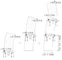
도 7은 라이너플레이트의 두께 측정시 탐촉자의 목표 이동 궤적(a)과 실제 이동 궤적(b)을 비교하여 나타내는 개념도이다.
도 8은 라이너플레이트의 두께 측정시 이동검사장치의 실제 이동 궤적을 나타내는 개념도이다.1 is a schematic view showing a liner plate inspection system according to an embodiment of the present invention.
2 is a perspective view showing a movement inspection device according to an embodiment of the present invention.
3 is a perspective view showing a lower portion of the magnetic wheel unit.
4 is a partial perspective view showing a lower portion of the movement inspection device.
5 is a cross-sectional view showing a state in which the probe holder unit is in contact with the liner plate.
6 is a conceptual diagram showing the movement of the probe when measuring the thickness of the liner plate using a movement inspection device.
7 is a conceptual diagram showing a comparison of a target movement trajectory (a) and an actual movement trajectory (b) of the probe when measuring the thickness of the liner plate.
8 is a conceptual diagram showing the actual movement trajectory of the movement inspection device when measuring the thickness of the liner plate.
본 발명은 다양한 변환을 가할 수 있고 여러 가지 실시예를 가질 수 있는 바, 특정 실시예를 예시하고 상세한 설명에 상세하게 설명하고자 한다. 그러나, 이는 본 발명을 특정한 실시 형태에 대해 한정하려는 것이 아니며, 본 발명의 사상 및 기술 범위에 포함되는 모든 변환, 균등물 내지 대체물을 포함하는 것으로 이해되어야 한다.The present invention can be applied to various transformations and can have various embodiments, and thus, specific embodiments will be illustrated and described in detail in the detailed description. However, this is not intended to limit the present invention to specific embodiments, and should be understood to include all conversions, equivalents, and substitutes included in the spirit and scope of the present invention.
본 발명에서 사용한 용어는 단지 특정한 실시예를 설명하기 위해 사용된 것으로, 본 발명을 한정하려는 의도가 아니다. 단수의 표현은 문맥상 명백하게 다르게 뜻하지 않는 한, 복수의 표현을 포함한다. 본 발명에서, '포함하다' 또는 '가지다' 등의 용어는 명세서상에 기재된 특징, 숫자, 단계, 동작, 구성요소, 부품 또는 이들을 조합한 것이 존재함을 지정하려는 것이지, 하나 또는 그 이상의 다른 특징들이나 숫자, 단계, 동작, 구성요소, 부품 또는 이들을 조합한 것들의 존재 또는 부가 가능성을 미리 배제하지 않는 것으로 이해되어야 한다.The terms used in the present invention are only used to describe specific embodiments, and are not intended to limit the present invention. Singular expressions include plural expressions unless the context clearly indicates otherwise. In the present invention, terms such as 'include' or 'have' are intended to indicate that there are features, numbers, steps, operations, components, parts, or combinations thereof described in the specification, and one or more other features. It should be understood that the existence or addition possibilities of fields or numbers, steps, operations, components, parts or combinations thereof are not excluded in advance.
이하, 첨부된 도면을 참조하여 본 발명의 바람직한 실시예들을 상세히 설명한다. 이 때, 첨부된 도면에서 동일한 구성 요소는 가능한 동일한 부호로 나타내고 있음에 유의한다. 또한, 본 발명의 요지를 흐리게 할 수 있는 공지 기능 및 구성에 대한 상세한 설명은 생략할 것이다. 마찬가지 이유로 첨부 도면에 있어서 일부 구성요소는 과장되거나 생략되거나 개략적으로 도시되었다.Hereinafter, preferred embodiments of the present invention will be described in detail with reference to the accompanying drawings. Note that, in this case, the same components in the accompanying drawings are indicated by the same reference numerals as possible. In addition, detailed descriptions of well-known functions and configurations that may obscure the subject matter of the present invention will be omitted. For the same reason, some components in the accompanying drawings are exaggerated, omitted, or schematically illustrated.
도 1은 본 발명의 일 실시예에 따른 라이너플레이트 검사 시스템을 나타내는 개략도이고, 도 2는 본 발명의 일 실시예에 따른 이동검사장치를 나타내는 사시도이며, 도 3은 마그네틱휠유닛의 하부를 나타내는 사시도이고, 도 4는 이동검사장치의 하부를 나타내는 일부 사시도이며, 도 5는 탐촉자홀더유닛이 라이너플레이트에 접촉되는 상태를 나타내는 단면도이다.1 is a schematic view showing a liner plate inspection system according to an embodiment of the present invention, FIG. 2 is a perspective view showing a movement inspection device according to an embodiment of the present invention, and FIG. 3 is a perspective view showing a lower portion of the
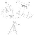
도 1에 도시된 바와 같이, 본 발명의 일 실시예에 따른 라이너플레이트 검사 시스템은, 원자력발전소의 격납건물 라이너플레이트(Containment Liner Plate: CLP, 10)에 부착되어 이동하면서 라이너플레이트의 두께를 측정하는 이동검사장치(100)와, 이동검사장치의 작동을 제어하는 검사제어장치(200)와, 이동검사장치의 탐촉자 위치를 측정하는 레이저위치측정장치(300)를 포함한다.As shown in Figure 1, the liner plate inspection system according to an embodiment of the present invention is attached to the containment building liner plate (Containment Liner Plate: CLP, 10) of a nuclear power plant to measure the thickness of the liner plate while moving It includes a
원자력발전소의 격납건물은 상면이 돔 형태의 지붕으로 덮힌 원통 형태를 이루는 철근 콘트리트 구조물이다.The containment building of a nuclear power plant is a reinforced concrete structure in the form of a cylinder whose top surface is covered with a dome-shaped roof.
격납건물 라이너플레이트(10)는 격납 건물의 누설 방지 기능의 유지 등을 위해 철근콘크리트벽의 내면에 설치되는 강판이다.The containment
라이너플레이트(10)는 매우 큰 곡률반경을 가진 원통 형태의 금속 판재이지만, 도 1에서는 편의상 라이너플레이트(10)를 그 일부만 금속 평판 형태로 도시하였다.The
이동검사장치(100)는 라이너플레이트(10)에 이동가능하게 부착되어 이동하면서 소정 간격마다 라이너플레이트(10)의 두께를 측정한다.The
검사제어장치(200)는 이동검사장치(100)의 이동 궤적과 두께 측정을 제어한다.The
레이저위치측정장치(300)는 이동검사장치(100)에 구비되는 탐촉자 위치를 측정하여 검사제어장치(200)로 알려준다. 레이저위치측정장치(300)는 탐촉자의 위치를 향하도록 실시간으로 탐촉자를 추적하다가, 이동검사장치(100)에서 위치측정의 트리거 신호를 발신하면 그 신호를 수신할 때 탐촉자의 위치를 측정하여 그 좌표 데이터를 검사제어장치(200)로 전달할 수 있다.The laser
후술하는 바와 같이, 이동검사장치(100)는 탐촉자가 검사 시작점과 검사 종료점에 있을 때에만 트리거 신호를 송출하여 레이저위치측정장치(300)는 검사 시작점과 검사 종료점의 좌표만 측정할 수 있다.As described later, the
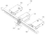
이동검사장치(100)는, 라이너플레이트(10)에 수평으로 배치되는 리니어가이드(150), 리니어가이드의 양측에 결합되어 리니어가이드를 상하이동시키는 한 쌍의 마그네틱휠유닛(120), 리니어가이드에 결합되며, 한 쌍의 마그네틱휠유닛 사이에 배치되는 탐촉자구동유닛(140), 및 탐촉자구동유닛에 의해 리니어가이드 상에 좌우로 이동되며 라이너플레이트의 두께를 측정하는 탐촉자홀더유닛(170)을 포함할 수 있다.The
라이너플레이트(10)는 수직의 벽면이고, 이 라이너플레이트(10)에 리니어가이드(150)가 수평으로 배치되어 상하로 이동될 수 있다.The
리니어가이드(150)는 좌우방향으로 긴 바(bar) 형태로 이루어지고, 이 리니어가이드(150)의 좌반부 중앙과 우반부 중앙에 각각 마그네틱휠유닛(120)이 결합될 수 있다.The
도 3에 도시된 바와 같이, 한 쌍의 마그네틱휠유닛(120)은 전기모터(121)에 의해 회전되고 자력에 의해 라이너플레이트(10)에 부착된 상태로 구름 운동을 하는 마그네틱휠(122)을 구비한다. 각 마그네틱휠유닛(120)은 라이너플레이트(10)에 밀착 지지됨에 반해, 리니어가이드(150)는 라이너플레이트(10)에서 소정 간격 이격될 수 있다.As shown in Figure 3, a pair of
탐촉자구동유닛(140)은 리니어가이드(150)의 중앙에 결합되어 탐촉자홀더유닛(170)을 리니어가이드(150) 상에서 좌우로 이동시킬 수 있다. 이를 위해, 탐촉자구동유닛(140)도 전기모터를 포함하고, 전기모터의 회전축으로부터 리니어가이드(150) 상에 이동 가능하게 장착된 탐촉자홀더유닛(170)으로 랙-벨트 구조에 의해 연결될 수 있다. 전기모터는 정역회전 가능하여 탐촉자홀더유닛(170)이 리니어가이드(150)의 좌측 단부 가까이와 우측 단부 가까이 사이에서 움직이도록 할 수 있다.The
탐촉자홀더유닛(170)은 탐촉자구동유닛(140)에 의해 리니어가이드(150) 상에 좌우로 이동되며 라이너플레이트(10)의 두께를 측정한다. 리니어가이드(150)는 탐촉자구동유닛(140)이 고정되는 프레임 역할과 탐촉자홀더유닛(170)의 이동을 안내하는 가이드 역할을 동시에 수행한다.The
탐촉자구동유닛(140)은 자이로센서(142)를 구비하여 리니어가이드(150)가 기울어지면 한 쌍의 마그네틱휠유닛(120)을 구동하여 수평하게 조정할 수 있다.The
이동검사장치(100)는 한 쌍의 마그네틱휠유닛(120)에 의해 상하로 움직일 때 각 마그네틱휠유닛(120)의 전기모터(121)를 동일한 회전수로 회전시키더라도 마그네틱휠(122)이 라이너플레이트(10) 상에서 미끄러져서 리니어가이드(150)가 기울어지는 경우가 있다.When the moving
한 쌍의 마그네틱휠유닛(120)의 전기모터(121)는 독립적으로 제어될 수 있기 때문에, 리니어가이드(150)가 기울어지면 한 쌍의 마그네틱휠유닛(120)의 각 전기모터(121) 중 적어도 하나를 작동하여 리니어가이드(150)가 수평하게 되도록 조정할 수 있다.Since the
마그네틱휠유닛(120)은, 리니어가이드에 결합되는 케이싱과, 케이싱의 내부 일측에 장착되는 전기모터(121)와, 전기모터에 의해 회전되는 한 쌍의 마그네틱![]()
![]()
케이싱은 하면이 개구된 직육면체 형태로 이루어질 수 있다. 케이싱의 내측면 사이에는 2개의 마그네틱휠(122)의 샤프트가 지면에 대해 상하로 장착될 수 있다.The casing may be formed in a rectangular parallelepiped shape with an open bottom surface. Between the inner surfaces of the casing, the shafts of the two
상측의 마그네틱휠(122)의 샤프트에는 전기모터(121)가 결합되고, 두 샤프트에 결합되는 풀리 사이에 벨트가 연결되어 상측 샤프트의 회전력을 하측 샤프트로 전달할 수 있다.An
마그네틱휠유닛(120)은, 마그네틱휠유닛의 주행량을 감지하기 위한 로터리 엔코더(124)를 더 포함하는 것이 바람직하다.The
로터리 엔코더(124)의 휠은 라이너플레이트(10)에 밀착되어 구름운동을 하고, 로터리 엔코더(124)는 그 휠의 회전수를 감지하여 검사제어장치(200)로 전달함으로써, 검사제어장치(200)가 마그네틱휠유닛(120)의 이동거리를 계산할 수 있다.The wheel of the
마그네틱휠(122)은 적어도 라이너플레이트(10)와 접촉하는 면이 폴리우레탄으로 코팅된 것이 바람직하다.The
라이너플레이트(10)는 금속 판재로 이루어지되, 그 내면은 페인트로 도장된다. 종래의 마그네틱휠은 그 외주면에 널링(knurling) 가공을 하여 요철을 형성함으로써 라이너플레이트(10)에서 미끄러지는 것을 줄이고자 하였다. 하지만, 마그네틱휠의 요철에 의해 라이너플레이트(10)의 도장면이 벗겨지거나 손상되는 문제점이 있었다.
이에 반해, 마그네틱휠(122)에 폴리우레탄 코팅을 함으로써 라이너플레이트(10)와의 마찰력은 증가시키되 라이너플레이트(10)의 도장면이 손상되는 것을 방지할 수 있다.On the other hand, by applying a polyurethane coating to the
또한, 케이싱은 라이너플레이트(10)에 평행한 제1축에 대해 회동가능하게 연결되는 제1힌지(131)와, 제1축에 교차하는 제2축에 대해 회동가능하게 연결되는 제2힌지(132)를 포함할 수 있다.Further, the casing includes a
마그네틱휠유닛(120)의 케이싱은 브라켓에 의해 리니어가이드(150)에 결합될 수 있다. 브라켓은 복수의 나사를 체결함으로써 리니어가이드(150)에 결합될 수 있다.The casing of the
브라켓은 리니어가이드(150)에 결합되는 제1브라켓부와 제1힌지(131)에 의해 연결되는 제2브라켓부로 구성될 수 있다. 제1힌지(131)의 회동축인 제1축은 라이너플레이트(10)의 길이방향에 평행하게 배치된다.The bracket may be composed of a first bracket portion coupled to the
제2브라켓부에는 마그네틱휠유닛(120)의 케이싱과 연결된 제2축이 제2힌지(132)에 의해 연결될 수 있다. 제2힌지(132)의 제2축은 제1축에 수직으로 배치된다.A second shaft connected to the casing of the
각 마그네틱휠(122)은 라이너플레이트(10)에 두 지점이 밀착되므로, 하나의 마그네틱휠유닛(120)에서 한 쌍의 마그네틱휠(122)은 네 지점이 라이너플레이트(10)에 밀착된다.Since each
라이너플레이트(10)는 매끈한 표면을 가진 것이 좋겠지만, 철판을 가공하여 연결하는 등의 설치 과정에서 굴곡진 표면을 갖게 된다.The
상기한 바와 같이, 마그네틱휠유닛(120)의 브라켓이 제1힌지(131) 및 제2힌지(132)에 의해 연결되기 때문에, 라이너플레이트(10)가 굴곡진 표면을 갖더라도 마그네틱휠(122)들이 라이너플레이트(10)의 표면에 모두 밀착될 수 있다.As described above, since the brackets of the
도 4에 도시된 바와 같이, 탐촉자구동유닛(140)은 라이너플레이트(10)에 슬라이딩 가능하게 밀착되는 마그네틱블록(144)을 더 포함하는 것이 바람직하다.As illustrated in FIG. 4, the
마그네틱블록(144)은 마그네틱휠유닛(120)의 부착력을 보완하고 이동검사장치(100)가 쉽게 기울어지지 않도록 할 수 있다.The
마그네틱블록(144)은 블록의 하면에 부착되는 복수의 자석판을 구비할 수 있다. 또한, 마그네틱블록(144)은 복수의 자석판의 상부 및 하부에 라이너플레이트(10)에 접촉하여 구름운동을 하는 복수의 볼을 구비할 수 있다. 그래서, 복수의 자석판은 복수의 볼에 의해 라이너플레이트(10)에 밀착되지 않고 조금 이격될 수 있어서 마그네틱블록(144)의 하면과 라이너플레이트(10) 사이의 마찰을 줄일 수 있다.The
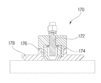
도 5(a)에는 굴곡진 라이너플레이트(10)에 탐촉자홀더유닛(170)이 밀착된 상태가 도시되어 있고, 도 5(b)에는 평평한 라이너플레이트(10)에 탐촉자홀더유닛(170)이 밀착된 상태가 도시되어 있다.5 (a) shows a state in which the
도 5에 도시된 바와 같이, 탐촉자홀더유닛(170)은, 라이너플레이트(10)로 초음파를 송수신하여 그 두께를 측정하는 초음파탐촉자(172)와, 초음파탐촉자의 전단부에 탐상수를 분사하는 탐상수노즐(176)과, 탐상수노즐의 전단부가 선택적으로 통과하는 구멍을 가지고 라이너플레이트(10)에 밀착되는 가이드디스크(178)를 포함할 수 있다.As shown in FIG. 5, the
초음파탐상법은 검사 대상에 가해진 초음파 빔이 균열과 같은 내부 결함을 만나면 반사되는 성질을 이용하여 검사 대상의 내부 결함을 검사하는 비파괴 검사 방법이다. 즉, 반사된 초음파에너지의 세기 및 반사 시간으로부터 결함의 존재 여부와 위치를 알아낼 수 있다.The ultrasonic inspection method is a non-destructive inspection method that inspects an internal defect of an inspection object by using the property that the ultrasonic beam applied to the inspection object is reflected when it encounters an internal defect such as a crack. That is, the presence and location of defects can be determined from the intensity and reflection time of the reflected ultrasonic energy.
초음파탐촉자(172)는 탐촉자홀더유닛(170)의 중심에 장착되어 초음파을 발신하고 반사되는 초음파를 수신할 수 있다.The
초음파는 매질을 통해 전달되는데, 초음파가 잘 전달될 수 있도록 탐상수노즐(176)은 초음파탐촉자(172)의 전단부에 탐상수를 분사하도록 설치된다.The ultrasonic waves are transmitted through the medium, and the
가이드디스크(178)는 중심에 탐상수노즐(176)의 전단부가 통과할 수 있는 구멍이 형성되고, 원형 디스크의 하면이 라이너플레이트(10)에 밀착되어 슬라이딩될 수 있도록 이루어진다.The
탐상수노즐(176)의 전단부는 그 외경이 점점 줄어들어 테이퍼지게 형성되고, 가이드디스크(178)의 중심 구멍도 하단으로 갈수록 내경이 점점 줄어들어 테이퍼지게 형성될 수 있다. 그래서, 탐상수노즐(176)의 전단부는 가이드디스크(178)의 중심 구멍보다 아래로 나올 수 있으나, 테이퍼진 형상에 의해 최대 돌출 지점에서 더이상 돌출되지 않도록 지지될 수 있다.The front end of the
가이드디스크(178)의 하면에 라이너플레이트(10)에 접촉하는 표면에는 연질 테플론 판을 부착함으로써, 마찰을 최소화하여 라이너플레이트(10)의 굴곡진 표면에도 잘 슬라이딩될 수 있다.By attaching a soft Teflon plate to the surface contacting the
탐촉자홀더유닛(170)은, 탐상수노즐(176)을 라이너플레이트(10)에 밀착시키는 스프링(174)을 더 포함할 수 있다.The
스프링(174)은 탐촉자홀더유닛(170)의 본체 내부에 장착되고 초음파탐촉자(172) 주위에 탐상수노즐(176)을 라이너플레이트(10) 쪽으로 밀어주도록 한 쌍 또는 두 쌍의 용수철 스프링으로 구성될 수 있다.The
이러한 스프링(174)이 탐상수노즐(176)을 라이너플레이트(10)에 밀착시킴으로써, 탐상수노즐(176)과 라이너플레이트(10) 사이의 틈을 통해 유출되는 탐상수의 양을 줄일 수 있다.By the
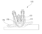
도 2에 도시된 바와 같이, 탐촉자홀더유닛(170)은 가이드디스크(178)에 형성된 관통공에 연결되어 탐상수를 흡입하는 탐상수회수호스(179)를 더 포함할 수 있다.As illustrated in FIG. 2, the
도 5에 도시된 바와 같이, 탐촉자홀더유닛(170)이 라이너플레이트(10)에 밀착되는 가이드디스크(178)와 탐상수노즐(176)을 밀어주는 스프링(174)을 구비하더라도, 라이너플레이트(10)에 굴곡진 부위가 있는 경우 가이드디스크(178)와 라이너플레이트(10) 사이에 틈이 형성되어 탐상수가 유출되는 것을 완전히 막기는 어렵다.As shown in FIG. 5, even if the
그래서, 가이드디스크(178)에 적어도 하나의 탐상수회수호스(179)를 연결함으로써 탐상수노즐(176)에서 새어나오는 탐상수를 곧바로 흡입하여 회수할 수 있도록 하는 것이 바람직하다.Therefore, it is preferable to connect the at least one flaw recovery hose 179 to the
또한, 리니어가이드(150)는 라이너플레이트(10)에 흘러내리는 탐상수를 긁어내는 와이퍼(160)를 더 포함할 수 있다.In addition, the
상기한 탐상수회수호스(179)로 탐상수를 회수하더라도 소량의 탐상수는 가이드디스크(178)와 라이너플레이트(10) 사이의 틈으로 유출되어 흘러내릴 수 있다. 그래서, 리니어가이드(150)의 아래에 단부가 고무 재질로 이루어진 와이퍼(160)를 설치함으로써, 흘러내리는 탐상수를 긁어낼 수 있다.Even if the flawless water is recovered by the flaw recovery hose 179, a small amount of flawless water may flow out and flow through the gap between the
그리고, 와이퍼(160)의 양 단부에도 탐상수회수호스를 연결하여 와이퍼(160)가 긁어내는 탐상수를 회수함으로써 리니어가이드(150)에 탐상수가 전혀 남지 않도록 할 수 있다.In addition, by connecting a flaw recovery hose to both ends of the
다음으로, 도 6 내지 도 8을 참조하여 라이너플레이트 검사 시스템의 제어방법 및 라이너플레이트 검사 방법을 설명한다.Next, the control method of the liner plate inspection system and the liner plate inspection method will be described with reference to FIGS. 6 to 8.
도 6은 이동검사장치를 이용하여 라이너플레이트의 두께 측정시 탐촉자의 이동을 나타내는 개념도이고, 도 7은 라이너플레이트의 두께 측정시 탐촉자의 목표 이동 궤적(a)과 실제 이동 궤적(b)을 비교하여 나타내는 개념도이며, 도 8은 라이너플레이트의 두께 측정시 이동검사장치의 실제 이동 궤적을 나타내는 개념도이다.Figure 6 is a conceptual diagram showing the movement of the probe when measuring the thickness of the liner plate using a movement inspection device, Figure 7 is a comparison of the target movement trajectory (a) and the actual movement trajectory (b) of the probe when measuring the thickness of the liner plate 8 is a conceptual diagram showing an actual movement trajectory of the movement inspection device when measuring the thickness of the liner plate.
본 발명의 일 실시예에 따른 격납건물 라이너플레이트(10) 검사 방법은, 상술한 라이너플레이트 검사 시스템을 이용하고, 이동검사장치(100)를 소정 높이 상방으로 이동시키는 단계, 탐촉자를 일측단에서 타측단으로 이동시키면서 소정 간격마다 라이너플레이트의 두께를 측정하여 저장하는 단계, 탐촉자의 두께 측정시 레이저위치측정장치(300)로 트리거 신호를 송출하는 단계, 레이저위치측정장치가 탐촉자의 위치를 추적하다가 트리거 신호를 수신하면 그 탐촉자의 위치를 저장하는 단계를 포함한다.Containment
먼저, 이동검사장치(100)를 라이너플레이트(10)의 소정 위치에 부착한 후 검사제어장치(200)를 조작하여 이동검사장치(100)의 이동 및 검사를 제어한다. 이동검사장치(100)를 소정 높이 상방으로 이동시키는 단계는 이와 같이 이동검사장치(100)의 탐촉자를 검사 시작 지점에 위치시키는 것을 포함한다.First, after attaching the
도 6에 도시된 바와 같이, 탐촉자홀더유닛(170)은 리니어가이드(150) 상에서 좌측에 위치된 상태에서 검사를 시작할 수 있다.As shown in FIG. 6, the
이때, 레이저위치측정장치(300)로 탐촉자의 위치를 측정하여 검사 시작점의 좌표 데이터를 검사제어장치(200)에 전달하여 저장한다.At this time, the position of the probe is measured by the laser
탐촉자구동유닛(140)을 작동시켜 탐촉자홀더유닛(170)을 오른쪽으로 움직이면서 소정의 폭(W)마다 초음파탐촉자(172)로 라이너플레이트(10)의 두께를 측정하여 그 데이터를 검사제어장치(200)에 저장한다.By operating the
이동검사장치(100)의 탐촉자가 라이너플레이트(10)의 두께를 측정할 때 이동검사장치(100)는 레이저위치측정장치(300)로 트리거 신호를 송출할 수 있다. 즉, 탐촉자가 검사 위치에서 두께를 측정할 때마다 레이저위치측정장치(300)로 그 검사 지점의 위치를 측정하여 그 좌표 데이터를 검사제어장치(200)에 전달하여 저장할 수 있다.When the probe of the
하지만, 이 경우 레이저위치측정장치(300)의 위치 측정 횟수와 측정된 위치 데이터가 너무 많아져서 시간이 많이 걸리고 비효율적이다. 그래서, 후술하는 바와 같이 레이저위치측정장치(300)의 위치 측정과 검사제어장치(200)의 좌표 데이터 저장은 단위 검사 영역의 검사 시작점과 검사 종료점에서만 실행될 수 있다.However, in this case, the number of position measurements of the laser
탐촉자홀더유닛(170)이 리니어가이드(150) 상에서 최우측에 도달하면, 한 쌍의 마그네틱휠유닛(120)을 작동시켜 상방으로 소정 높이(H) 이동시킨다.When the
그런후, 다시 탐촉자구동유닛(140)을 작동시켜 탐촉자홀더유닛(170)을 왼쪽으로 움직이면서 소정의 폭(W)마다 초음파탐촉자(172)로 라이너플레이트(10)의 두께를 측정하여 그 데이터를 검사제어장치(200)에 저장한다.Then, by operating the
다시 탐촉자홀더유닛(170)을 상방으로 이동 후 좌우로 움직이며 라이너플레이트(10)의 두께를 측정하는 것을 수차례 반복한다. 그러면, 처음에 입력했던 탐촉자홀더유닛(170)의 이동 궤적에 따른 이동이 완료되고 검사의 종료점에 도달하게 된다.The
검사 종료점에서 두께 측정을 한 후에도, 레이저위치측정장치(300)로 탐촉자의 위치를 측정하여 검사 종료점의 좌표 데이터를 검사제어장치(200)에 전달하여 저장한다.Even after the thickness is measured at the inspection end point, the position of the probe is measured by the laser
이렇게 탐촉자의 검사 시작점과 검사 종료점 사이를 하나의 단위 검사 영역으로 설정할 수 있다.In this way, the probe start point and the test end point can be set as one unit inspection area.
탐촉자 위치 저장 단계에서, 검사 시작점과 검사 종료점을 기준으로 직사각형 내부에 생성되는 가상의 좌표를 탐촉자의 두께 측정 데이터와 매칭시킬 수 있다.In the step of storing the position of the probe, virtual coordinates generated inside the rectangle based on the inspection start point and the inspection end point may be matched with the thickness measurement data of the probe.
이동검사장치(100)로 단위 검사 영역을 실제로 이동하면서 라이너플레이트(10)의 두께를 측정하고 그 데이터를 검사제어장치(200)에 저장한다. 또한, 이동검사장치(100)로부터 트리거 신호를 받는 레이저위치측정장치(300)는 단위 검사 영역의 검사 시작점과 검사 종료점의 위치를 측정하여 그 좌표 데이터를 검사제어장치(200)에 저장한다. 검사제어장치(200)는 검사 시작점과 검사 종료점에 의해 결정되는 직사각형으로부터 계산되는 검사 지점들의 위치 좌표들을 실제로 측정된 두께 데이터와 각각 매칭하여 저장할 수 있다.While actually moving the unit inspection area with the
도 7(a)에 예시된 바와 같이, 단위 검사 영역은 가로로 N개의 검사 지점과 세로로 M개의 행으로 이루어진 검사 지점들을 포함할 수 있다. 그래서, 단위 검사 영역은 N×M개의 검사 지점들을 가진 직사각형 영역이 입력되는 목표 검사 영역으로 설정될 수 있다. 하나의 단위 검사 영역을 검사(스캔)하면 라이너플레이트(10)의 두께에 관한 N×M개의 행렬 데이터가 생성된다.As illustrated in FIG. 7A, the unit inspection area may include N inspection points horizontally and M inspection points vertically. Thus, the unit inspection area may be set as a target inspection area into which a rectangular area having N × M inspection points is input. When one unit inspection area is inspected (scanned), N × M matrix data regarding the thickness of the
하지만, 도 7(b)에 도시된 바와 같이, 3번의 단위 검사 영역을 이동한 후에는 목표 검사 영역과 실제 검사 영역에 있어서 오차가 발생할 수 있다. 이는 마그네틱휠(122)에 슬립이 발생하기 때문으로서, 도 7(b)의 경우, 3번의 단위 검사 영역을 스캔하는 동안 우측의 마그네틱휠유닛(120)에 슬립이 발생하는 경우에 탐촉자의 실제 검사 영역을 목표 검사 영역과 비교하여 나타낸 것이다.However, as shown in FIG. 7 (b), after moving the unit inspection area 3 times, an error may occur in the target inspection area and the actual inspection area. This is because the slip occurs in the
이와 같이, 마그네틱휠(122)에 슬립이 발생하고 명령한 이동 궤적과 실제 이동 궤적에 오차가 발생하고, 복수회의 단위 검사 영역을 연속적으로 스캔할수록 그 오차는 누적되어 점점 커지게 된다. 도 7(b)에 도시된 바와 같이, 3번의 단위 검사 영역을 스캔한 후 높이 오차와 횡방향 오차가 상당히 크게 발생했음을 확인할 수 있다.As described above, slip occurs in the
이러한 오차를 줄이기 위해, 도 8에 도시된 바와 같이, 본 발명에서는 단위 검사 영역의 스캔이 종료되는 시점에 탐촉자구동유닛(140)에 구비된 자이로센서(142)로 이동검사장치(100)의 기울기를 감지한 후 마그네틱휠유닛(120)을 구동하여 이동검사장치(100)를 수평하게 조정한다.In order to reduce this error, as shown in FIG. 8, in the present invention, the tilt of the
그러면 오차가 발생하더라도 하나의 단위 검사 영역에 대해서만 오차가 발생하고, 복수의 단위 검사 영역에 대한 검사를 수행하더라도 그 오차가 누적되지 않게 되므로, 오차는 허용 범위 이내에 있을 수 있다.Then, even if an error occurs, an error occurs only for one unit inspection area, and even if a plurality of unit inspection areas are inspected, the error does not accumulate, so the error may be within an allowable range.
도 8에서는 단위 검사 영역의 스캔 폭이 600mm이고 스캔 거리(높이)가 1000mm인 것을 예시적으로 표시하였으나, 이러한 수치에 한정되지는 않는다. 스캔 폭과 스캔 거리는 라이너플레이트(10)의 크기와 이동검사장치의 오차 정도에 따라 적절히 설정될 수 있다.In FIG. 8, the scan width of the unit inspection area is 600 mm and the scan distance (height) is 1000 mm, but the present invention is not limited thereto. The scan width and scan distance can be appropriately set according to the size of the
검사제어장치(200)는 스캔 시작점과 스캔 종료점을 마주보는 꼭지점으로 하는 직사각형으로부터 각 탐촉점들의 위치 좌표를 계산할 수 있다. 이러한 위치 좌표들을 검사제어장치(200)에 저장되어 있는 N×M개의 두께 측정 데이터와 매칭시켜서, 각 위치 좌표에 대응하는 두께 데이터로 저장할 수 있다.The
이상, 본 발명의 일 실시예에 대하여 설명하였으나, 해당 기술 분야에서 통상의 지식을 가진 자라면 특허청구범위에 기재된 본 발명의 사상으로부터 벗어나지 않는 범위 내에서, 구성 요소의 부가, 변경, 삭제 또는 추가 등에 의해 본 발명을 다양하게 수정 및 변경시킬 수 있을 것이며, 이 또한 본 발명의 권리범위 내에 포함된다고 할 것이다.As described above, one embodiment of the present invention has been described, but those skilled in the art can add, change, delete, or add components within the scope of the present invention as described in the claims. The present invention may be variously modified and changed by the like, and it will be said that this is also included within the scope of the present invention.
10: 격납건물 라이너플레이트
100: 이동검사장치
120: 마그네틱휠유닛
121: 모터
122: 마그네틱휠
124: 로터리 엔코더
131: 제1힌지
132: 제2힌지
140: 탐촉자구동유닛
142: 자이로센서
144: 마그네틱블록
150: 리니어가이드
160: 와이퍼
170: 탐촉자홀더유닛
172: 초음파탐촉자
174: 스프링
176: 탐상수노즐
178: 가이드디스크
179: 탐상수회수호스
200: 검사제어장치
300: 레이저위치측정장치10: containment building liner plate
100: mobile inspection device
120: magnetic wheel unit
121: motor
122: magnetic wheel
124: rotary encoder
131: first hinge
132: second hinge
140: probe driving unit
142: gyro sensor
144: magnetic block
150: linear guide
160: wiper
170: probe holder unit
172: ultrasonic probe
174: spring
176: flaw detection nozzle
178: guide disc
179: Detective recovery hose
200: inspection control device
300: laser position measuring device
Claims (20)
상기 이동검사장치를 소정 높이 상방으로 이동시키는 단계;
상기 탐촉자를 일측단에서 타측단으로 이동시키면서 소정 간격마다 라이너플레이트의 두께를 측정하여 저장하는 단계;
상기 탐촉자의 두께 측정시 상기 레이저위치측정장치로 트리거 신호를 송출하는 단계;
상기 레이저위치측정장치가 상기 탐촉자의 위치를 추적하다가 트리거 신호를 수신하면 그 탐촉자의 위치를 저장하는 단계를 포함하는 라이너플레이트 검사 시스템의 제어방법.A moving inspection device attached to the liner plate of a containment building of a nuclear power plant to measure the thickness of the liner plate while moving, an inspection control device to control the operation of the moving inspection device, and a laser position measurement to measure the position of the probe of the moving inspection device As a control method of a liner plate inspection system comprising a device,
Moving the movement inspection device upward a predetermined height;
Measuring and storing the thickness of the liner plate at predetermined intervals while moving the probe from one end to the other;
Sending a trigger signal to the laser position measuring device when measuring the thickness of the probe;
And the laser position measuring device tracking the position of the probe and storing the position of the probe when a trigger signal is received.
상기 탐촉자 위치 저장 단계 후에,
상기 이동검사장치 이동 단계, 라이너플레이트 두께 측정 저장 단계, 트리거 신호 송출 단계, 탐촉자 위치 저장 단계를 소정 횟수 반복하여 단위 검사 영역을 검사하는 라이너플레이트 검사 시스템의 제어방법.According to claim 1,
After the probe position storage step,
Control method of the liner plate inspection system for inspecting the unit inspection area by repeating the moving inspection device moving step, the liner plate thickness measurement storage step, the trigger signal transmission step, and the probe position storage step a predetermined number of times.
상기 이동검사장치는,
라이너플레이트에 수평으로 배치되는 리니어가이드;
상기 리니어가이드의 양측에 결합되어 리니어가이드를 상하이동시키는 한 쌍의 마그네틱휠유닛;
상기 리니어가이드에 결합되며, 상기 한 쌍의 마그네틱휠유닛 사이에 배치되는 탐촉자구동유닛;
상기 탐촉자구동유닛에 의해 리니어가이드 상에 좌우로 이동되며 라이너플레이트의 두께를 측정하는 탐촉자홀더유닛을 포함하는 라이너플레이트 검사 시스템의 제어방법.According to claim 2,
The mobile inspection device,
A linear guide disposed horizontally on the liner plate;
A pair of magnetic wheel units coupled to both sides of the linear guide to move the linear guide up and down;
A probe driving unit coupled to the linear guide and disposed between the pair of magnetic wheel units;
A control method of a liner plate inspection system including a probe holder unit that is moved left and right on a linear guide by the probe driving unit and measures the thickness of the liner plate.
상기 트리거 신호 송출 단계에서, 상기 단위 검사 영역의 검사 시작점과 검사 종료점에서만 트리거 신호를 송출하고,
상기 탐촉자 위치 저장 단계에서, 상기 검사 시작점과 검사 종료점을 기준으로 직사각형 내부에 생성되는 가상의 좌표를 탐촉자의 두께 측정 데이터와 매칭시키는 라이너플레이트 검사 시스템의 제어방법.According to claim 3,
In the trigger signal transmission step, the trigger signal is transmitted only at the inspection start point and the inspection end point of the unit inspection area,
In the step of storing the probe position, a control method of a liner plate inspection system that matches virtual coordinates generated inside a rectangle based on the inspection start point and inspection end point with thickness measurement data of the probe.
상기 단위 검사 영역의 검사 종료 후에,
상기 탐촉자구동유닛에 구비된 자이로센서로 기울기를 감지하고, 상기 이동검사장치에 구비된 한 쌍의 마그네틱휠유닛을 구동하여 이동검사장치를 수평하게 조정하는 단계를 더 포함하는 라이너플레이트 검사 시스템의 제어방법.The method according to any one of claims 2 to 4,
After completion of the inspection of the unit inspection area,
Controlling the liner plate inspection system further comprising the step of horizontally adjusting the movement inspection device by detecting a tilt with a gyro sensor provided in the probe driving unit and driving a pair of magnetic wheel units provided in the movement inspection device. Way.
상기 마그네틱휠유닛은,
상기 리니어가이드에 결합되는 케이싱과,
상기 케이싱의 내부 일측에 장착되는 전기모터와,
상기 전기모터에 의해 회전되는 적어도 하나 이상의 마그네틱휠과,
마그네틱휠유닛의 주행량을 감지하기 위한 로터리 엔코더를 포함하는 라이너플레이트 검사 시스템의 제어방법.The method of claim 5,
The magnetic wheel unit,
Casing coupled to the linear guide,
An electric motor mounted on one side of the casing,
At least one magnetic wheel rotated by the electric motor,
A control method of a liner plate inspection system including a rotary encoder for detecting the traveling amount of a magnetic wheel unit.
상기 케이싱은 상기 라이너플레이트에 평행한 제1축에 대해 회동가능하게 연결되는 제1힌지와, 상기 제1축에 교차하는 제2축에 대해 회동가능하게 연결되는 제2힌지를 포함하는 라이너플레이트 검사 시스템의 제어방법.The method of claim 6,
The casing inspects a liner plate including a first hinge rotatably connected to a first axis parallel to the liner plate, and a second hinge rotatably connected to a second axis intersecting the first axis. How to control the system.
상기 탐촉자구동유닛은,
상기 탐촉자홀더유닛을 이동시키는 전기모터와,
상기 라이너플레이트에 슬라이딩 가능하게 밀착되는 마그네틱블록을 포함하는 라이너플레이트 검사 시스템의 제어방법.The method of claim 7,
The probe driving unit,
An electric motor for moving the probe holder unit,
A control method of a liner plate inspection system including a magnetic block slidably in close contact with the liner plate.
상기 탐촉자홀더유닛은,
상기 라이너플레이트로 초음파를 송수신하여 그 두께를 측정하는 초음파탐촉자와,
상기 초음파탐촉자의 전단부에 탐상수를 분사하는 탐상수노즐과,
상기 탐상수노즐의 전단부가 선택적으로 통과하는 구멍을 가지고 상기 라이너플레이트에 밀착되는 가이드디스크와,
상기 탐상수노즐을 상기 라이너플레이트에 밀착시키는 스프링을 포함하는 라이너플레이트 검사 시스템의 제어방법.According to claim 3,
The probe holder unit,
And the ultrasonic transducer to transmit and receive ultrasonic waves to the liner plate to measure its thickness,
A probe water nozzle for spraying the probe water to the front end of the ultrasonic probe,
A guide disc having a hole through which the front end of the flaw detection nozzle is selectively passed, and in close contact with the liner plate,
Method for controlling a liner plate inspection system including a spring for bringing the flaw water nozzle into close contact with the liner plate.
상기 탐촉자홀더유닛은 상기 가이드디스크에 형성된 관통공에 연결되어 탐상수를 흡입하는 탐상수회수호스를 더 포함하고,
상기 리니어가이드는 상기 라이너플레이트에 흘러내리는 탐상수를 긁어내는 와이퍼를 더 포함하는 라이너플레이트 검사 시스템의 제어방법.The method of claim 9,
The probe holder unit further includes a flaw recovery hose that is connected to a through hole formed in the guide disc and sucks flaw water,
The linear guide further comprises a wiper for scraping off the flaw water flowing on the liner plate.
상기 이동검사장치를 소정 높이 상방으로 이동시키는 단계;
상기 탐촉자를 일측단에서 타측단으로 이동시키면서 소정 간격마다 라이너플레이트의 두께를 측정하여 저장하는 단계;
상기 탐촉자의 두께 측정시 상기 레이저위치측정장치로 트리거 신호를 송출하는 단계; 및
상기 레이저위치측정장치가 상기 탐촉자의 위치를 추적하다가 트리거 신호를 수신하면 그 탐촉자의 위치를 저장하는 단계를 포함하는 라이너플레이트 검사 방법.A moving inspection device attached to the liner plate of a containment building of a nuclear power plant to measure the thickness of the liner plate while moving, an inspection control device to control the operation of the moving inspection device, and a laser position measurement to measure the position of the probe of the moving inspection device A method for inspecting a liner plate using a liner plate inspection system including a device,
Moving the movement inspection device upward a predetermined height;
Measuring and storing the thickness of the liner plate at predetermined intervals while moving the probe from one end to the other;
Sending a trigger signal to the laser position measuring device when measuring the thickness of the probe; And
And when the laser position measuring device tracks the position of the probe and receives a trigger signal, storing the position of the probe.
상기 탐촉자 위치 저장 단계 후에,
상기 이동검사장치 이동 단계, 라이너플레이트 두께 측정 저장 단계, 트리거 신호 송출 단계, 탐촉자 위치 저장 단계를 소정 횟수 반복하여 단위 검사 영역을 검사하는 라이너플레이트 검사 방법.The method of claim 11,
After the probe position storage step,
A liner plate inspection method for inspecting the unit inspection area by repeating the moving inspection device moving step, the liner plate thickness measurement storage step, the trigger signal transmission step, and the probe position storage step a predetermined number of times.
상기 이동검사장치는,
라이너플레이트에 수평으로 배치되는 리니어가이드;
상기 리니어가이드의 양측에 결합되어 리니어가이드를 상하이동시키는 한 쌍의 마그네틱휠유닛;
상기 리니어가이드에 결합되며, 상기 한 쌍의 마그네틱휠유닛 사이에 배치되는 탐촉자구동유닛;
상기 탐촉자구동유닛에 의해 리니어가이드 상에 좌우로 이동되며 라이너플레이트의 두께를 측정하는 탐촉자홀더유닛을 포함하는 라이너플레이트 검사 방법.The method of claim 12,
The mobile inspection device,
A linear guide disposed horizontally on the liner plate;
A pair of magnetic wheel units coupled to both sides of the linear guide to move the linear guide up and down;
A probe driving unit coupled to the linear guide and disposed between the pair of magnetic wheel units;
A liner plate inspection method comprising a probe holder unit that moves from side to side on a linear guide by the probe driving unit and measures the thickness of the liner plate.
상기 트리거 신호 송출 단계에서, 상기 단위 검사 영역의 검사 시작점과 검사 종료점에서만 트리거 신호를 송출하고,
상기 탐촉자 위치 저장 단계에서, 상기 검사 시작점과 검사 종료점을 기준으로 직사각형 내부에 생성되는 가상의 좌표를 탐촉자의 두께 측정 데이터와 매칭시키는 라이너플레이트 검사 방법.The method of claim 13,
In the trigger signal transmission step, the trigger signal is transmitted only at the inspection start point and the inspection end point of the unit inspection area,
In the step of storing the position of the probe, a liner plate inspection method of matching virtual coordinates generated inside the rectangle with the thickness measurement data of the probe based on the inspection start point and the inspection end point.
상기 단위 검사 영역의 검사 종료 후에,
상기 탐촉자구동유닛에 구비된 자이로센서로 기울기를 감지하고, 상기 이동검사장치에 구비된 한 쌍의 마그네틱휠유닛을 구동하여 이동검사장치를 수평하게 조정하는 단계를 더 포함하는 라이너플레이트 검사 방법.The method according to any one of claims 12 to 14,
After completion of the inspection of the unit inspection area,
And detecting a tilt with a gyro sensor provided in the probe driving unit, and driving the pair of magnetic wheel units provided in the moving inspection device to horizontally adjust the moving inspection device.
상기 마그네틱휠유닛은,
상기 리니어가이드에 결합되는 케이싱과,
상기 케이싱의 내부 일측에 장착되는 전기모터와,
상기 전기모터에 의해 회전되는 적어도 하나 이상의 마그네틱휠과,
마그네틱휠유닛의 주행량을 감지하기 위한 로터리 엔코더를 포함하는 라이너플레이트 검사 방법.The method of claim 15,
The magnetic wheel unit,
Casing coupled to the linear guide,
An electric motor mounted on one side of the casing,
At least one magnetic wheel rotated by the electric motor,
Liner plate inspection method including a rotary encoder for detecting the amount of travel of the magnetic wheel unit.
상기 케이싱은 상기 라이너플레이트에 평행한 제1축에 대해 회동가능하게 연결되는 제1힌지와, 상기 제1축에 교차하는 제2축에 대해 회동가능하게 연결되는 제2힌지를 포함하는 라이너플레이트 검사 방법.The method of claim 6,
The casing inspects a liner plate including a first hinge rotatably connected to a first axis parallel to the liner plate, and a second hinge rotatably connected to a second axis intersecting the first axis. Way.
상기 탐촉자구동유닛은,
상기 탐촉자홀더유닛을 이동시키는 전기모터와,
상기 라이너플레이트에 슬라이딩 가능하게 밀착되는 마그네틱블록을 포함하는 라이너플레이트 검사 방법.The method of claim 17,
The probe driving unit,
An electric motor for moving the probe holder unit,
Liner plate inspection method comprising a magnetic block slidably in close contact with the liner plate.
상기 탐촉자홀더유닛은,
상기 라이너플레이트로 초음파를 송수신하여 그 두께를 측정하는 초음파탐촉자와,
상기 초음파탐촉자의 전단부에 탐상수를 분사하는 탐상수노즐과,
상기 탐상수노즐의 전단부가 선택적으로 통과하는 구멍을 가지고 상기 라이너플레이트에 밀착되는 가이드디스크와,
상기 탐상수노즐을 상기 라이너플레이트에 밀착시키는 스프링을 포함하는 라이너플레이트 검사 방법.The method of claim 13,
The probe holder unit,
And the ultrasonic transducer to transmit and receive ultrasonic waves to the liner plate to measure its thickness,
A probe water nozzle for spraying the probe water to the front end of the ultrasonic probe,
A guide disc having a hole through which the front end of the flaw detection nozzle is selectively passed, and in close contact with the liner plate,
Liner plate inspection method comprising a spring for bringing the flawless nozzle into close contact with the liner plate.
상기 탐촉자홀더유닛은 상기 가이드디스크에 형성된 관통공에 연결되어 탐상수를 흡입하는 탐상수회수호스를 더 포함하고,
상기 리니어가이드는 상기 라이너플레이트에 흘러내리는 탐상수를 긁어내는 와이퍼를 더 포함하는 라이너플레이트 검사 방법.The method of claim 19,
The probe holder unit further includes a flaw recovery hose that is connected to a through hole formed in the guide disc and sucks flaw water,
The linear guide further comprises a wiper for scraping the flaw water flowing on the liner plate.
Priority Applications (1)
| Application Number | Priority Date | Filing Date | Title |
|---|---|---|---|
| KR1020180112286A KR102164938B1 (en) | 2018-09-19 | 2018-09-19 | Method for controlling containment liner plate test system and method for testing liner plate |
Applications Claiming Priority (1)
| Application Number | Priority Date | Filing Date | Title |
|---|---|---|---|
| KR1020180112286A KR102164938B1 (en) | 2018-09-19 | 2018-09-19 | Method for controlling containment liner plate test system and method for testing liner plate |
Publications (2)
| Publication Number | Publication Date |
|---|---|
| KR20200032975A true KR20200032975A (en) | 2020-03-27 |
| KR102164938B1 KR102164938B1 (en) | 2020-10-13 |
Family
ID=69959278
Family Applications (1)
| Application Number | Title | Priority Date | Filing Date |
|---|---|---|---|
| KR1020180112286A KR102164938B1 (en) | 2018-09-19 | 2018-09-19 | Method for controlling containment liner plate test system and method for testing liner plate |
Country Status (1)
| Country | Link |
|---|---|
| KR (1) | KR102164938B1 (en) |
Citations (3)
| Publication number | Priority date | Publication date | Assignee | Title |
|---|---|---|---|---|
| KR830009475A (en) * | 1981-03-12 | 1983-12-21 | 로버트 제이. 에드워스 | Coordinate Measuring Device |
| KR101829582B1 (en) | 2017-05-29 | 2018-02-14 | 한전케이피에스 주식회사 | Repair method for containment wall and liner plate used for repair |
| KR101886574B1 (en) * | 2017-06-13 | 2018-08-07 | 한전케이피에스 주식회사 | Repair system of containment wall |
-
2018
- 2018-09-19 KR KR1020180112286A patent/KR102164938B1/en active IP Right Grant
Patent Citations (3)
| Publication number | Priority date | Publication date | Assignee | Title |
|---|---|---|---|---|
| KR830009475A (en) * | 1981-03-12 | 1983-12-21 | 로버트 제이. 에드워스 | Coordinate Measuring Device |
| KR101829582B1 (en) | 2017-05-29 | 2018-02-14 | 한전케이피에스 주식회사 | Repair method for containment wall and liner plate used for repair |
| KR101886574B1 (en) * | 2017-06-13 | 2018-08-07 | 한전케이피에스 주식회사 | Repair system of containment wall |
Also Published As
| Publication number | Publication date |
|---|---|
| KR102164938B1 (en) | 2020-10-13 |
Similar Documents
| Publication | Publication Date | Title |
|---|---|---|
| US11085885B2 (en) | Pipe joint inspection | |
| US8759780B2 (en) | Pipeline inspection | |
| US5362962A (en) | Method and apparatus for measuring pipeline corrosion | |
| KR102013918B1 (en) | Moving test apparatus and liner plate test system | |
| US11420692B2 (en) | Surface wave detection of surface defects | |
| US20070140403A1 (en) | Method for inspection and maintenance of an inside of a nuclear power reactor | |
| US8215174B2 (en) | Inspection apparatus for tubular members | |
| JP5954241B2 (en) | Self-propelled inspection device and inspection method for metal plate | |
| JPH02225702A (en) | Method and device for positioning transversing direction of member moving along railroad rail | |
| CN212540183U (en) | Rod surface defect on-line measuring system | |
| US11731281B2 (en) | Automation in a robotic pipe coating system | |
| US6530278B1 (en) | Ultrasonic testing of tank car welds | |
| KR100975330B1 (en) | Multi Channel Ultrasonic Welding Inspection System and Control Method | |
| KR102164938B1 (en) | Method for controlling containment liner plate test system and method for testing liner plate | |
| KR20210058519A (en) | A testing device for pipe using ultra-sonic wave c-scan device | |
| JP3567583B2 (en) | Underwater mobile robot positioning method | |
| US11982632B2 (en) | System and method for internal coating of offshore pipeline weld joints with fluorescent anti-corrosion coatings and wet inspection | |
| TWI752635B (en) | Mobile inspection device, mobile inspection method, and manufacturing method of steel | |
| JP2000249783A (en) | Position detection method of in-core pipe welding part and device thereof | |
| US20220236232A1 (en) | Ultrasonic inspection device and inspection method | |
| JP3925470B2 (en) | Rehabilitation tube inspection device and rehabilitation tube inspection system using the device | |
| EP2947419A1 (en) | Device for inspecting a surface of a wall | |
| Sattar et al. | Amphibious NDT robots | |
| CN112902865B (en) | Automatic detection system and automatic detection method for surface defects of bent pipe body | |
| CN117269311B (en) | Pressure vessel defect detection device and method based on surface wave signal correlation analysis |
Legal Events
| Date | Code | Title | Description |
|---|---|---|---|
| E902 | Notification of reason for refusal | ||
| E701 | Decision to grant or registration of patent right | ||
| GRNT | Written decision to grant |