KR20200029496A - Rolling bearing and retainer - Google Patents
Rolling bearing and retainer Download PDFInfo
- Publication number
- KR20200029496A KR20200029496A KR1020207002711A KR20207002711A KR20200029496A KR 20200029496 A KR20200029496 A KR 20200029496A KR 1020207002711 A KR1020207002711 A KR 1020207002711A KR 20207002711 A KR20207002711 A KR 20207002711A KR 20200029496 A KR20200029496 A KR 20200029496A
- Authority
- KR
- South Korea
- Prior art keywords
- pillar
- annular body
- axial direction
- pillars
- hook
- Prior art date
Links
Images


Classifications
-
- F—MECHANICAL ENGINEERING; LIGHTING; HEATING; WEAPONS; BLASTING
- F16—ENGINEERING ELEMENTS AND UNITS; GENERAL MEASURES FOR PRODUCING AND MAINTAINING EFFECTIVE FUNCTIONING OF MACHINES OR INSTALLATIONS; THERMAL INSULATION IN GENERAL
- F16C—SHAFTS; FLEXIBLE SHAFTS; ELEMENTS OR CRANKSHAFT MECHANISMS; ROTARY BODIES OTHER THAN GEARING ELEMENTS; BEARINGS
- F16C33/00—Parts of bearings; Special methods for making bearings or parts thereof
- F16C33/30—Parts of ball or roller bearings
- F16C33/46—Cages for rollers or needles
- F16C33/4617—Massive or moulded cages having cage pockets surrounding the rollers, e.g. machined window cages
- F16C33/4641—Massive or moulded cages having cage pockets surrounding the rollers, e.g. machined window cages comprising two annular parts joined together
- F16C33/4647—Massive or moulded cages having cage pockets surrounding the rollers, e.g. machined window cages comprising two annular parts joined together made from metal, e.g. two cast parts joined by rivets
-
- F—MECHANICAL ENGINEERING; LIGHTING; HEATING; WEAPONS; BLASTING
- F16—ENGINEERING ELEMENTS AND UNITS; GENERAL MEASURES FOR PRODUCING AND MAINTAINING EFFECTIVE FUNCTIONING OF MACHINES OR INSTALLATIONS; THERMAL INSULATION IN GENERAL
- F16C—SHAFTS; FLEXIBLE SHAFTS; ELEMENTS OR CRANKSHAFT MECHANISMS; ROTARY BODIES OTHER THAN GEARING ELEMENTS; BEARINGS
- F16C19/00—Bearings with rolling contact, for exclusively rotary movement
- F16C19/22—Bearings with rolling contact, for exclusively rotary movement with bearing rollers essentially of the same size in one or more circular rows, e.g. needle bearings
- F16C19/24—Bearings with rolling contact, for exclusively rotary movement with bearing rollers essentially of the same size in one or more circular rows, e.g. needle bearings for radial load mainly
- F16C19/28—Bearings with rolling contact, for exclusively rotary movement with bearing rollers essentially of the same size in one or more circular rows, e.g. needle bearings for radial load mainly with two or more rows of rollers
-
- F—MECHANICAL ENGINEERING; LIGHTING; HEATING; WEAPONS; BLASTING
- F16—ENGINEERING ELEMENTS AND UNITS; GENERAL MEASURES FOR PRODUCING AND MAINTAINING EFFECTIVE FUNCTIONING OF MACHINES OR INSTALLATIONS; THERMAL INSULATION IN GENERAL
- F16C—SHAFTS; FLEXIBLE SHAFTS; ELEMENTS OR CRANKSHAFT MECHANISMS; ROTARY BODIES OTHER THAN GEARING ELEMENTS; BEARINGS
- F16C33/00—Parts of bearings; Special methods for making bearings or parts thereof
- F16C33/30—Parts of ball or roller bearings
- F16C33/46—Cages for rollers or needles
- F16C33/48—Cages for rollers or needles for multiple rows of rollers or needles
-
- F—MECHANICAL ENGINEERING; LIGHTING; HEATING; WEAPONS; BLASTING
- F16—ENGINEERING ELEMENTS AND UNITS; GENERAL MEASURES FOR PRODUCING AND MAINTAINING EFFECTIVE FUNCTIONING OF MACHINES OR INSTALLATIONS; THERMAL INSULATION IN GENERAL
- F16C—SHAFTS; FLEXIBLE SHAFTS; ELEMENTS OR CRANKSHAFT MECHANISMS; ROTARY BODIES OTHER THAN GEARING ELEMENTS; BEARINGS
- F16C19/00—Bearings with rolling contact, for exclusively rotary movement
- F16C19/22—Bearings with rolling contact, for exclusively rotary movement with bearing rollers essentially of the same size in one or more circular rows, e.g. needle bearings
- F16C19/44—Needle bearings
- F16C19/48—Needle bearings with two or more rows of needles
-
- F—MECHANICAL ENGINEERING; LIGHTING; HEATING; WEAPONS; BLASTING
- F16—ENGINEERING ELEMENTS AND UNITS; GENERAL MEASURES FOR PRODUCING AND MAINTAINING EFFECTIVE FUNCTIONING OF MACHINES OR INSTALLATIONS; THERMAL INSULATION IN GENERAL
- F16C—SHAFTS; FLEXIBLE SHAFTS; ELEMENTS OR CRANKSHAFT MECHANISMS; ROTARY BODIES OTHER THAN GEARING ELEMENTS; BEARINGS
- F16C2226/00—Joining parts; Fastening; Assembling or mounting parts
- F16C2226/50—Positive connections
- F16C2226/70—Positive connections with complementary interlocking parts
- F16C2226/72—Positive connections with complementary interlocking parts with bayonet joints, i.e. parts are rotated to create positive interlock
-
- F—MECHANICAL ENGINEERING; LIGHTING; HEATING; WEAPONS; BLASTING
- F16—ENGINEERING ELEMENTS AND UNITS; GENERAL MEASURES FOR PRODUCING AND MAINTAINING EFFECTIVE FUNCTIONING OF MACHINES OR INSTALLATIONS; THERMAL INSULATION IN GENERAL
- F16C—SHAFTS; FLEXIBLE SHAFTS; ELEMENTS OR CRANKSHAFT MECHANISMS; ROTARY BODIES OTHER THAN GEARING ELEMENTS; BEARINGS
- F16C33/00—Parts of bearings; Special methods for making bearings or parts thereof
- F16C33/30—Parts of ball or roller bearings
- F16C33/46—Cages for rollers or needles
- F16C33/4617—Massive or moulded cages having cage pockets surrounding the rollers, e.g. machined window cages
- F16C33/4641—Massive or moulded cages having cage pockets surrounding the rollers, e.g. machined window cages comprising two annular parts joined together
- F16C33/4652—Massive or moulded cages having cage pockets surrounding the rollers, e.g. machined window cages comprising two annular parts joined together made from plastic, e.g. two injection moulded parts joined by a snap fit
-
- F—MECHANICAL ENGINEERING; LIGHTING; HEATING; WEAPONS; BLASTING
- F16—ENGINEERING ELEMENTS AND UNITS; GENERAL MEASURES FOR PRODUCING AND MAINTAINING EFFECTIVE FUNCTIONING OF MACHINES OR INSTALLATIONS; THERMAL INSULATION IN GENERAL
- F16C—SHAFTS; FLEXIBLE SHAFTS; ELEMENTS OR CRANKSHAFT MECHANISMS; ROTARY BODIES OTHER THAN GEARING ELEMENTS; BEARINGS
- F16C33/00—Parts of bearings; Special methods for making bearings or parts thereof
- F16C33/30—Parts of ball or roller bearings
- F16C33/46—Cages for rollers or needles
- F16C33/467—Details of individual pockets, e.g. shape or roller retaining means
- F16C33/4682—Details of individual pockets, e.g. shape or roller retaining means of the end walls, e.g. interaction with the end faces of the rollers
-
- F—MECHANICAL ENGINEERING; LIGHTING; HEATING; WEAPONS; BLASTING
- F16—ENGINEERING ELEMENTS AND UNITS; GENERAL MEASURES FOR PRODUCING AND MAINTAINING EFFECTIVE FUNCTIONING OF MACHINES OR INSTALLATIONS; THERMAL INSULATION IN GENERAL
- F16C—SHAFTS; FLEXIBLE SHAFTS; ELEMENTS OR CRANKSHAFT MECHANISMS; ROTARY BODIES OTHER THAN GEARING ELEMENTS; BEARINGS
- F16C33/00—Parts of bearings; Special methods for making bearings or parts thereof
- F16C33/30—Parts of ball or roller bearings
- F16C33/46—Cages for rollers or needles
- F16C33/52—Cages for rollers or needles with no part entering between, or touching, the bearing surfaces of the rollers
Abstract
보유 지지기는, 제1 환형체 및 복수의 기둥을 갖는 보유 지지기 본체와, 제2 환형체와, 보유 지지기 본체와 제2 환형체를 연결하기 위한 축 부재를 구비한다. 복수의 기둥은, 축 부재를 삽입 관통시키는 관통 구멍이 형성되어 있는 제1 기둥과, 축방향 일방측의 단부에 갈고리를 갖는 제2 기둥을 포함한다. 제2 환형체는, 제2 기둥과 연결되는 부분에, 갈고리를 수용하는 오목부를 갖고, 오목부의 일부에 갈고리와 걸림 결합하는 돌기가 형성되어 있다.The retainer includes a retainer body having a first annular body and a plurality of pillars, a second annular body, and a shaft member for connecting the retainer body and the second annular body. The plurality of pillars include a first pillar having a through hole through which the shaft member is inserted and a second pillar having a hook at one end in the axial direction. The second annular body has a concave portion for accommodating the hook at a portion connected to the second pillar, and a protrusion engaging with the hook is formed in a part of the concave portion.
Description
본 발명의 양태는, 구름 베어링, 및 구름 베어링의 전동체를 보유 지지하는 보유 지지기에 관한 것이다.An aspect of the present invention relates to a rolling bearing and a holding device for holding a rolling element of the rolling bearing.
구름 베어링은, 축을 지지하기 위해서 여러 분야에서 널리 사용되고 있으며, 일반적으로, 내륜, 외륜, 이들 내륜과 외륜의 사이에 마련되어 있는 복수의 전동체, 및 이들 전동체를 보유 지지하는 환형 보유 지지기를 구비하고 있다.Rolling bearings are widely used in various fields to support the shaft, and generally have an inner ring, an outer ring, a plurality of rolling elements provided between these inner and outer rings, and an annular holding device for holding the rolling elements. have.
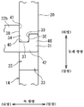
이와 같은 구름 베어링이 구비하고 있는 보유 지지기로서, 예를 들어 황동제이며, 도 8에 도시한 바와 같이, 리벳(91)에 의해 조립되는 것이 있다(예를 들어, 특허문헌 1 참조). 도 8은, 이러한 보유 지지기(99)의 일부를 나타내는 사시도이다. 이 보유 지지기(99)는, 원환 형상인 제1 환형체(98) 및 이 제1 환형체(98)로부터 축방향으로 연장되어 있는 복수의 기둥(97)을 갖는 보유 지지기 본체(96)와, 복수의 기둥(97)의 축방향 일방측에 마련되어 있는 원환형 제2 환형체(95)를 구비하고 있다. 제1 환형체(98)와 제2 환형체(95)의 사이이며 둘레 방향으로 인접하는 기둥(97, 97) 사이의 공간(94)이, 도시하지 않은 전동체를 보유 지지하는 포켓으로 된다.As a holding device provided with such a rolling bearing, for example, it is made of brass, and as shown in Fig. 8, it is assembled by a rivet 91 (for example, see Patent Document 1). 8 is a perspective view showing a part of the
보유 지지기 본체(96)에 있어서, 모든 기둥(97), 및 제1 환형체(98) 중 기둥(97)이 연결되는 부분(98a)에는, 리벳(91)의 축부(91b)를 삽입 관통시키는 축방향으로 긴 제1 구멍(93)이 형성되어 있다. 또한, 제2 환형체(95)에 있어서, 기둥(97)과 동일한 둘레 방향 피치로 축방향으로 관통하는 제2 구멍(92)이 형성되어 있다. 이들 제1 구멍(93) 및 제 2 구멍(92)에 대해서 리벳(91)의 축부(91b)를 삽입 관통하고, 리벳 단부(91a)를 코오킹함으로써, 보유 지지기 본체(96)와 제2 환형체(95)가 일체로 된다.In the retainer
리벳(91)의 축부(91b)의 직경은, 예를 들어 2밀리미터 정도이고, 보유 지지기 본체(96)에 형성되어 있는 제1 구멍(93)의 직경 및 제2 환형체(95)에 형성되어 있는 제2 구멍(92)의 직경은, 축부(91b)의 직경보다도 약간 크다. 보유 지지기 본체(96)에 제1 구멍(93)을 형성하기 위해서는, 기둥(97) 및 제1 환형체(98)에 대해서 공구를 축방향으로 관통시킬 필요가 있지만, 형성하는 제1 구멍(93)은 직경이 작고 축방향으로 긴 점에서, 그 가공이 어렵고, 공구가 가늘어 꺾이는 경우가 있다. 게다가, 이러한 구멍 가공을, 모든 기둥(97)에 대해서 행할 필요가 있어, 보유 지지기(99)의 제조는 곤란하다는 문제점이 있다. 또한, 상기와 같은 구멍 가공을 마쳐도, 기둥(97)과 동수의 리벳(91)을 하나씩 해머 등을 사용하여 코오킹하는 작업이 필요하여, 조립에 수고를 요한다는 문제점이 있다.The diameter of the
보유 지지기(99)는(형번에 따라 다르지만) 예를 들어 12 내지 20개 정도의 기둥(97)을 구비하고 있으며, 기둥(97)의 수가 많아질수록, 그 제조(구멍 가공)나 조립 작업에 많은 공정수를 요한다는 문제점이 있다.The holding device 99 (although depending on the model number) is provided with, for example, about 12 to 20
그래서, 본 발명의 양태는, 보유 지지기 본체와 제2 환형체를 연결하기 위한 구멍 가공이나 연결 작업의 수고가 삭감되어, 제조 및 조립 공정수를 저감시키는 것이 가능한 보유 지지기, 및 이러한 보유 지지기를 구비하고 있는 구름 베어링을 제공하는 것을 목적으로 한다.Thus, an aspect of the present invention is a holding device capable of reducing the number of manufacturing and assembly processes by reducing the labor of a hole processing or connecting operation for connecting the holding body and the second annular body, and such holding support. An object of the present invention is to provide a rolling bearing equipped with a flag.
본 발명의 일 형태에서는, 제1 환형체 및 당해 제1 환형체로부터 축방향 일방측으로 연장되어 있는 복수의 기둥을 갖는 보유 지지기 본체와, 복수의 상기 기둥의 축방향 일방측에 마련되어 있는 제2 환형체와, 상기 기둥의 수보다도 적고 상기 보유 지지기 본체와 상기 제2 환형체를 축방향으로 관통해서 연결하기 위한 축 부재를 구비하고, 상기 제1 환형체와 상기 제2 환형체의 사이이며 둘레 방향으로 인접하는 상기 기둥의 사이 공간이 전동체를 보유 지지하는 포켓을 형성하고, 상기 복수의 기둥은, 상기 축 부재를 삽입 관통시키는 관통 구멍이 형성되어 있는 제1 기둥과, 축방향 일방측의 단부에 갈고리를 갖는 제2 기둥을 포함하고, 상기 제2 환형체는, 상기 제2 기둥과 연결되는 부분에, 상기 갈고리를 수용하는 오목부를 갖고, 당해 오목부에 상기 갈고리와 걸림 결합하는 돌기가 마련되어 있다.In one aspect of the present invention, a holder body having a first annular body and a plurality of pillars extending axially from the first annular body, and a second provided on one axial side of the plurality of pillars And an annular body and a shaft member for less than the number of the pillars and connecting the holder body and the second annular body through the axial direction, between the first annular body and the second annular body. The space between the adjacent pillars in the circumferential direction forms a pocket for holding the rolling element, and the plurality of pillars include a first pillar having a through hole through which the shaft member is inserted, and an axial one side. It includes a second pillar having a hook at the end of the, and the second annular body has a concave portion for receiving the claw in the portion connected to the second pillar, and the claw in the concave portion It is provided with a frost and engaging protrusions.
이 보유 지지기에 의하면, 복수의 기둥에는, 축 부재가 관통함으로써 제2 환형체와 연결되는 제1 기둥과, 갈고리와 돌기의 걸림 결합에 의해 제2 환형체와 연결되는 제2 기둥이 포함되는 구성으로 된다. 즉, 보유 지지기 본체와 제2 환형체를 연결하기 위해서, 모든 기둥에 대해서 축 부재를 삽입 관통시킬 필요가 없고, 복수의 기둥 중 일부인 제1 기둥에 있어서 축 부재를 삽입 관통시켜, 다른 제2 기둥에 있어서 갈고리와 돌기를 걸림 결합시키면 된다. 따라서, 모든 기둥, 및 이들 모든 기둥에 대응하는 제1 환형체 및 제2 환형체 각각의 부분에, 축 부재를 삽입 관통시키는 관통 구멍을 형성할 필요가 없다. 이 때문에, 축 부재에 의해 보유 지지기 본체와 제2 환형체를 연결하기 위한 구멍 가공이나 축 부재에 의한 연결 작업의 수고가 삭감되어, 보유 지지기의 제조 및 조립 공정수를 저감하는 것이 가능해진다. 또한, 상기 「축 부재에 의한 연결 작업」의 예로서는, 예를 들어 축 부재가 리벳인 경우, 코오킹 작업이다.According to this holding device, the plurality of pillars include a first pillar connected to the second annular body by passing through the shaft member, and a second pillar connected to the second annular body by engaging the hook and the protrusion. Becomes That is, in order to connect the holder body and the second annular body, it is not necessary to insert and pass through the shaft member for all the pillars, and the shaft member is inserted through the first pillar, which is a part of the plurality of pillars, and the other second In the pillars, hooks and protrusions can be engaged. Therefore, it is not necessary to form through holes for inserting and penetrating the shaft member in all the pillars, and portions of the first annular body and the second annular body corresponding to all the pillars. For this reason, it is possible to reduce the number of steps of manufacturing and assembling the retainer by reducing the labor of the hole processing for connecting the retainer main body and the second annular body by the shaft member or the connecting operation by the shaft member. . In addition, as an example of the said "connection work by a shaft member", for example, when a shaft member is a rivet, it is a coking operation.
또한, 상기 복수의 기둥은, 추가로, 축방향 일방측의 단부면이 상기 제2 환형체의 축방향 타방측의 면에 대해서 접촉 가능하며 당해 제2 환형체와 비연결 상태에 있는 제3 기둥을 포함하는 것이 바람직하다. 이 구성에 의하면, 복수의 기둥에는, 제1 기둥 및 제2 기둥 외에, 제3 기둥이 포함되고, 축 부재를 사용하여 보유 지지기 본체와 제2 환형체를 연결하는 개소를 더 줄여서, 보유 지지기의 제조 및 조립 공정수를 더한층 저감시키는 것이 가능해진다.In addition, the plurality of pillars, in addition, one end surface of the axial one side is in contact with the surface of the other side of the axial direction of the second annular body, the third pillar in a non-connected state with the second annular body It is preferable to include. According to this configuration, in addition to the first pillar and the second pillar, the plurality of pillars includes a third pillar, and further reduces the position of connecting the holder body and the second annular body using a shaft member, thereby retaining the pillar. It becomes possible to further reduce the number of manufacturing and assembly processes of the group.
또한, 상기 오목부는, 상기 돌기의 둘레 방향 일방측의 옆에, 상기 갈고리를 축방향으로 삽입 가능하게 하는 스페이스를 포함하는 것이 바람직하다. 이 구성에 의하면, 보유 지지기 본체와 제2 환형체를 조합할 때, 제2 환형체의 오목부에 마련되어 있는 상기 스페이스에 대해서, 보유 지지기 본체의 제2 기둥의 갈고리를, 축방향으로부터 삽입시키고, 그 후, 보유 지지기 본체에 대해서 제2 환형체를 둘레 방향 일방측으로 회전시키면, 갈고리를 돌기에 걸림 결합시키는 것이 가능한 구성이 얻어진다. 그리고, 갈고리와 돌기가 걸림 결합한 상태에서, 제1 기둥을 관통하는 축 부재에 의해 보유 지지기 본체와 제2 환형체를 연결하면, 보유 지지기 본체와 제2 환형체는 둘레 방향으로 회전 불능으로 되어, 갈고리와 돌기의 걸림 결합이 풀리지 않는다. 따라서, 상기 구성에 의하면, 갈고리와 돌기의 걸림 결합에 의한 보유 지지기의 조립이 용이하게 되고, 게다가, 조립이 완료되면, 갈고리와 돌기의 걸림 결합에 의해 보유 지지기 본체와 제2 환형체는 기구적으로 결합되어, 보유 지지기의 강성이 높아진다.In addition, it is preferable that the concave portion includes a space that allows the hook to be inserted in the axial direction next to one side in the circumferential direction of the protrusion. According to this configuration, when the retainer main body and the second annular body are combined, the hook of the second pillar of the retainer main body is inserted into the space provided in the recess of the second annular body from the axial direction. Then, when the second annular body is rotated to one side in the circumferential direction with respect to the holder main body, a structure capable of engaging the hook with the protrusion is obtained. Then, in the state where the hook and the projection are engaged, when the holder body and the second annular body are connected by the shaft member penetrating the first pillar, the holder body and the second annular body cannot rotate in the circumferential direction. It becomes, and the engagement of the hook and the protrusion is not released. Therefore, according to the above configuration, the assembly of the retainer is facilitated by the engaging engagement of the hook and the projection. Moreover, when the assembly is completed, the retainer main body and the second annular body are engaged by the engagement of the hook and the projection. Mechanically coupled, the rigidity of the retainer is increased.
또한, 상기 오목부는, 직경 방향 외측 또는 내측, 및 축방향 타방측을 향해서 개구되어 있으며, 상기 돌기는, 축방향 일방측을 향하는 제1 면과, 직경 방향을 향하는 제2 면과, 축방향 타방측을 향하는 제3 면을 갖고, 상기 갈고리는, 상기 제1 면에 대향하는 제4 면과, 상기 제2 면에 대향하는 제5 면을 갖고, 상기 제2 기둥의 축방향 일방측의 단부면이, 상기 제3 면에 대향함과 함께, 당해 단부면으로부터 상기 갈고리가 돌출되어 있는 것이 바람직하다. 이 구성에 의하면, 돌기가 갖는 각 면에 대해서 갈고리가 갖는 각 면이 대향함으로써, 돌기와 갈고리가 걸림 결합하고, 보유 지지기 본체와 제2 환형체가 축방향에 대하여 분리 불가능하게 된다.In addition, the concave portion is open in the radially outer or inner side, and toward the other side in the axial direction, and the projection includes a first surface facing the axial one side, a second surface facing the radial direction, and an axial other side A third surface facing the side, the claw having a fourth surface facing the first surface, and a fifth surface facing the second surface, an end surface on one side in the axial direction of the second pillar It is preferable that the hook protrudes from the end face while facing the third face. According to this configuration, when each surface of the hook is opposed to each surface of the protrusion, the protrusion and the hook are engaged and the retainer main body and the second annular body cannot be separated in the axial direction.
본 발명의 다른 양태에서는, 구름 베어링은, 내륜과, 외륜과, 상기 내륜과 상기 외륜의 사이에 마련되어 있는 복수의 전동체와, 상기 복수의 전동체를 보유 지지하는 환형 보유 지지기를 구비하고, 상기 보유 지지기가, 상기한 각 구성을 구비하고 있다.In another aspect of the present invention, the rolling bearing includes an inner ring, an outer ring, a plurality of rolling elements provided between the inner ring and the outer ring, and an annular holding device for holding the plurality of rolling elements. The holding | maintenance machine is equipped with each structure mentioned above.
이 구름 베어링에 의하면, 보유 지지기의 제조 및 조립에 있어서, 축 부재에 의해 보유 지지기 본체와 제2 환형체를 연결하기 위한 구멍 가공이나 축 부재에 의한 연결 작업의 수고가 삭감되어, 공정수를 저감시키는 것이 가능해진다.According to this rolling bearing, in the manufacture and assembly of the retainer, the number of steps required for the machining of the hole for connecting the retainer body and the second annular body by the shaft member or the connection work by the shaft member are reduced. It becomes possible to reduce.
본 발명의 양태에 의하면, 보유 지지기의 제조 및 조립에 있어서, 축 부재에 의해 보유 지지기 본체와 제2 환형체를 연결하기 위한 구멍 가공이나 축 부재에 의한 연결 작업의 수고가 삭감되어, 공정수를 저감시키는 것이 가능해진다. 이 결과, 보유 지지기의 비용 저하(구름 베어링의 비용 저하)에 공헌할 수 있다.According to an aspect of the present invention, in manufacturing and assembling a retainer, the processing of the hole for connecting the retainer body and the second annular body by the shaft member or the labor of the connection work by the shaft member is reduced, and the process It becomes possible to reduce the number. As a result, it is possible to contribute to the reduction in the cost of the retainer (lower cost of the rolling bearing).
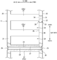
도 1은, 구름 베어링의 단면도이다.
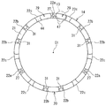
도 2는, 환 형상인 보유 지지기를 평면적으로 전개한 상태의 도면이며, 직경 방향 외측에서 본 경우의 도면이다.
도 3은, 보유 지지기 본체를 축방향 일방측에서 본 도면이다.
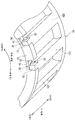
도 4는, 제2 기둥 및 제2 환형체의 일부를 나타내는 사시도이다.
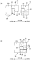
도 5의 (A) 및 도 5의 (B)는, 보유 지지기의 일부를 둘레 방향을 따라 본 단면도이며, 도 5의 (A)는 갈고리와 돌기가 걸림 결합하기 전의 상태(비걸림 결합 상태)를 나타내고, 도 5의 (B)는 갈고리와 돌기가 걸림 결합한 상태를 나타내고 있다.
도 6은, 보유 지지기의 일부를 축방향 일방측에서 본 도면이다.
도 7은, 제2 기둥의 갈고리, 및 제2 환형체의 오목부의 돌기의 변형예를 나타내는 도면이다.
도 8은, 종래의 보유 지지기의 일부를 나타내는 사시도이다.1 is a cross-sectional view of a rolling bearing.
Fig. 2 is a view of a planar deployment of the annular holder, and is a view when viewed from the outside in the radial direction.
3 is a view of the holder main body viewed from one side in the axial direction.
4 is a perspective view showing a part of the second pillar and the second annular body.
5A and 5B are cross-sectional views of a part of the retainer along the circumferential direction, and FIG. 5A is a state before hooks and protrusions are engaged (non-engaged state) ), And FIG. 5 (B) shows a state in which the hook and the projection are engaged.
6 is a view of a part of the retainer viewed from one side in the axial direction.
7 is a view showing a modified example of the projection of the hook of the second pillar and the concave portion of the second annular body.
8 is a perspective view showing a part of a conventional retainer.
도 1은 구름 베어링의 단면도이다. 이 구름 베어링(10)은, 내륜(11)과, 외륜(12)과, 이들 내륜(11)과 외륜(12)의 사이에 마련되어 있는 복수의 전동체와, 이들 복수의 전동체를 보유 지지하는 환형 보유 지지기(14)를 구비하고 있다. 본 실시 형태의 전동체는 원통 롤러(13)이며, 구름 베어링(10)은 원통 롤러 베어링이다.1 is a cross-sectional view of a rolling bearing. The rolling
본 실시 형태의 내륜(11)은, 원통형의 내륜 본체(15)와, 환형 플랜지 링(16)을 갖고 있으며, 내륜 본체(15)의 축방향 일방측에 플랜지 링(16)을 배열한 상태로 하고, 이들을 조합함으로써 내륜(11)이 구성된다. 내륜 본체(15)의 외주측에 원통 롤러(13)가 구름 접촉하는 내륜 궤도면(17)이 형성되어 있으며, 내륜 본체(15)의 축방향 타방측에 직경 방향 외측으로 돌출되어 있는 내부 플랜지부(18)가 마련되어 있다. 본 실시 형태의 외륜(12)은, 원통형이며, 내주측에 원통 롤러(13)가 구름 접촉하는 외륜 궤도면(19)이 형성되어 있다. 외륜(12)의 축방향 일방측 및 타방측에 직경 방향 내측으로 돌출되어 있는 외측 플랜지부(19a, 19b)가 마련되어 있다. 본 실시 형태에서는, 원통 롤러(13)가 축방향으로 2열 나란히 마련되어 있다. 2열의 원통 롤러(13)가, 하나의 보유 지지기(14)에 의해 보유 지지되어 있다. 내륜(11), 외륜(12), 및 원통 롤러(13)는, 예를 들어 베어링 강제이다. 도 1에 도시한 구름 베어링(10)은, 철강 압연기에 있어서의 워크 롤 스러스트용 베어링으로서 사용된다.The
도 2는, 환형인 보유 지지기(14)를 평면적으로 전개한 상태의 도면이며, 직경 방향 외측에서 본 경우의 도면이다. 도 1 및 도 2에 도시한 바와 같이, 보유 지지기(14)는, 2분할 구조를 갖고 있다. 즉, 보유 지지기(14)는, 제1 환형체(제1 환 형상부)(21) 및 이 제1 환형체(21)로부터 축방향 일방측으로 연장되어 있는 복수의 기둥(기둥부)(22)을 갖는 보유 지지기 본체(20)와, 복수의 기둥(22)의 축방향 일방측에 마련되어 있는 제2 환형체(30)를 구비하고 있다. 제1 환형체(21)는 원환 형상이며, 이 제1 환형체(21)의 축방향 일방측으로부터 더욱 축방향 일방측을 향해서 기둥(22)이 직선 형상으로 연장되어 마련되어 있다. 제2 환형체(30)는 원환형 부재이다. 본 실시 형태의 보유 지지기 본체(20) 및 제2 환형체(30)는, 구리 합금(황동)제이지만, 기타 금속 재료여도 된다. 보유 지지기 본체(20)와 제2 환형체(30)는, 별도의 부재에 의해 구성되어 있으며, 후에도 설명하겠지만 리벳(23)(도 2 참조) 및 갈고리(31)와 돌기(34)의 걸림 결합에 의해 연결되어 일체로 되어 있다.FIG. 2 is a view of the
도 2에 있어서, 보유 지지기(14)는, 보유 지지기 본체(20)와 제2 환형체(30)를 축방향으로 관통해서 연결하기 위한 축 부재로서 상기 리벳(23)을 구비하고 있다. 리벳(23)은, 직선형 축부(24)와, 이 축부(24)의 축방향 일방측에 마련되어 있는 직경이 확대된 머리부(25)를 갖고 있다. 축부(24)를, 제2 환형체(30)에 마련되어 있는 관통 구멍(28) 및 보유 지지기 본체(20)에 마련되어 있는 관통 구멍(27)에 삽입 관통하고, 축방향 타방측의 단부를 코오킹함(소성 변형시킴)으로써 직경이 확대된 코오킹부(26)가 형성되고, 이에 의해, 보유 지지기 본체(20)와 제2 환형체(30)가 분리 불능으로 된다. 또한, 리벳(23) 대신에, 도시하지는 않았지만, 다른 축 부재로서 가늘고 긴 볼트를 채용할 수 있고, 이 볼트를 상기 관통 구멍(27, 28)에 삽입 관통시켜, 축방향 일방측의 볼트 머리부와, 축방향 타방측에 있어서 이 볼트에 나사 결합하는 너트에 의해, 보유 지지기 본체(20)와 제2 환형체(30)를 연결하는 구성으로 해도 된다.In Fig. 2, the
보유 지지기 본체(20)의 제1 관통 구멍(27)은, 제1 환형체(21) 및 기둥(22)을 축방향으로 관통하고 있다. 후에도 설명하겠지만, 본 실시 형태에서는, 제1 관통 구멍(27)은 리벳(23)과 동수인 3군데에 마련되어 있다(도 3 참조).The first through
제2 관통 구멍(28)은 제2 환형체(30)를 축방향으로 관통하고 있다. 제2 환형체(30)에 있어서, 제2 관통 구멍(28)은, 제1 관통 구멍(27)과 동수이며 제1 관통 구멍(27)과 둘레 방향에 대하여 동일한 위치에 마련되어 있다.The second through
이들 관통 구멍(27, 28)은 리벳(23)의 축부(24)의 직경보다도 약간 큰 직경의 구멍이다. 리벳(23)의 축부(24)가 관통하고 있는 기둥(22)을 제1 기둥(22a)이라고 칭한다. 도 2에 도시한 바와 같이, 보유 지지기(14)는, 제1 기둥(22a) 이외에, 제2 기둥(22b) 및 제3 기둥(22c)을 갖고 있다. 제2 기둥(22b) 및 제3 기둥(22c)의 구성에 대해서는, 후술한다.These through
도 3은, 보유 지지기 본체(20)를 축방향 일방측에서 본 도면이다. 본 실시 형태의 보유 지지기 본체(20)는, 15개의 기둥(22)을 갖고 있으며, 이 중, 관통 구멍(27)이 형성되어 있는 제1 기둥(22a)은 3개이다. 제1 기둥(22a)은 둘레 방향을 따라 균등하게(본 실시 형태에서는 120도 이격되어) 배치되어 있다. 그리고, 15개의 기둥(22) 중 6개가 제2 기둥(22b)이며, 나머지 6개가 제3 기둥(22c)이다. 하나의 제1 기둥(22a)과 다른 제1 기둥(22a)의 사이에, 제2 기둥(22b) 및 제3 기둥(22c)이 마련되어 있다. 본 실시 형태에서는, 하나의 제1 기둥(22a)과 다른 제1 기둥(22a)의 사이에, 2개의 제2 기둥(22b) 및 2개의 제3 기둥(22c)이 마련되어 있다. 또한, 기둥(22)의 수는, 구름 베어링(10)의 형번(크기)에 따라 다양하고, 또한, 제1 기둥(22a), 제2 기둥(22b), 및 제3 기둥(22c)의 각각의 수 및 둘레 방향의 배치는, 도 3에 도시한 형태 이외여도 된다. 단, 제1 기둥(22a) 및 제2 기둥(22b)에 대해서는, 각각을 둘레 방향으로 분산시키는(균등하게 배치하는) 것이 좋으며, 도 3에 도시한 형태와 같이, 복수 개(2개)의 제2 기둥(22b)을 1조로 하여, 그 조를 둘레 방향으로 분산시켜도 된다(균등하게 배치해도 된다).3 is a view of the holder
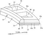
도 2 및 도 3에 도시한 바와 같이, 제2 기둥(22b)은, 축방향 일방측의 단부에 갈고리(31)를 갖고 있다. 도 4는, 제2 기둥(22b) 및 제2 환형체(30)의 일부를 나타내는 사시도이다. 제2 환형체(30) 중 제2 기둥(22b)과 연결되는 부분(32)에, 갈고리(31)를 수용하는 오목부(33)가 형성되어 있으며, 이 오목부(33)의 일부에 갈고리(31)와 걸림 결합하는 돌기(34)가 마련되어 있다. 오목부(33)(및 돌기(34))는, 제2 기둥(22b)과 동수이며 제2 기둥(22b)과 둘레 방향에 대하여 동일한 위치에 마련되어 있다. 보유 지지기 본체(20)가 갖는 제2 기둥(22b)의 갈고리(31)가, 제2 환형체(30)의 오목부(33)에 형성되어 있는 돌기(34)에 걸림 결합함으로써, 이들 보유 지지기 본체(20)와 제2 환형체(30)는 연결되고, 축방향에 대하여 분리 불가능하게 된다.2 and 3, the
도 4에 도시한 바와 같이, 제2 환형체(30)에 있어서, 오목부(33)는, 적어도 직경 방향 외측 및 축방향 타방측을 향해 개구되어 있으며, 본 실시 형태에서는, 더욱 축방향 일방측을 향해 개구되어 있다. 즉, 오목부(33)는, 제2 환형체(30)를 그 내주측을 남기고 축방향으로 관통되어 있다. 이 오목부(33)의 둘레 방향의 일부에 돌기(34)가 마련되어 있다. 또한, 본 실시 형태에서는, 오목부(33)에 있어서, 둘레 방향 일방측에 축방향으로 관통하고 있는 스페이스(공간부)(35)가 마련되어 있으며, 그 둘레 방향 타방측에 축방향의 장벽으로 되는 돌기(34)가 마련되어 있다.As shown in Fig. 4, in the second
도 5의 (A) 및 5의 (B)는, 보유 지지기(14)의 일부(제2 기둥(22b) 및 그 주위)를 둘레 방향을 따라 본 확대 단면도이며, 도 5의 (A)는 갈고리(31)와 돌기(34)가 걸림 결합하기 전의 상태(비걸림 결합 상태)를 나타내고 있으며, 도 5의 (B)는 갈고리(31)와 돌기(34)가 걸림 결합한 상태를 나타내고 있다.5A and 5B are enlarged cross-sectional views of a part of the holder 14 (
돌기(34)는, 직육면체 내지 입방체 형상을 구비하고 있으며, 축방향 일방측을 향하는 제1 면(36)과, 직경 방향 외측을 향하는 제2 면(37)과, 축방향 타방측을 향하는 제3 면(38)을 갖고 있다.The
이에 반하여, 갈고리(31)는, 제2 기둥(22b)의 축방향 일방측의 단부면(41)으로부터 축방향 일방측으로 돌출되어 있는 축방향 돌출부(42)와, 이 축방향 돌출부(42)의 축방향 일방측의 선단부로부터 직경 방향 내측으로 돌출되어 있는 직경 방향 돌출부(43)를 갖고 있다. 이에 의해, 갈고리(31)가 돌기(34)에 걸림 결합한 상태에 있어서(도 5의 (B) 참조), 갈고리(31)는, 제1 면(36)에 대향하는 제4 면(39)과, 제2 면(37)에 대향하는 제5 면(40)을 갖는 구성으로 된다. 그리고, 제2 기둥(22b)의 축방향 일방측의 단부면(41)이, 제3 면(38)에 대향한다. 제4 면(39)은, 직경 방향 돌출부(43)의 축방향 타방측의 면이며, 제5 면(40)은, 축방향 돌출부(42)의 직경 방향 내측의 면이다.On the other hand, the
도 5의 (B)에 도시한 바와 같이, 갈고리(31)가 돌기(34)에 걸림 결합한 상태에서, 제1 면(36)과 제4 면(39)이 면 접촉 가능하고, 제2 면(37)과 제5 면(40)이 면 접촉 가능하며, 제2 기둥(22b)의 축방향 일방측의 단부면(41)과 제3 면(38)이 면 접촉 가능해진다. 제4 면(39)과 제2 기둥(22b)의 단부면(41)의 사이에 돌기(34)가 개재됨으로써, 제2 기둥(22b)과 제2 환형체(30)는 축 방향으로 분리 불가능하게 되어 연결되고, 제5 면(40)과 제2 면(37)이 접촉함으로써, 기둥(22b)과 제2 환형체(30)의 상호의 직경 방향의 위치 결정이 된다.As shown in (B) of FIG. 5, in the state in which the
도 2 및 도 3에 도시한 바와 같이, 제3 기둥(22c)은, 축방향 일방측에, 제2 기둥(22b)이 갖는 갈고리(31)가 마련되어 있지 않고, 또한, 제1 기둥(22a)과 같이 리벳(22)용 관통 구멍(27)이 형성되어 있지 않으며, 제3 기둥(22c)의 축방향 일방측의 단부면(44)은, 환 형상인 보유 지지기(14)의 중심축 C1(도 3 참조)로 직행하는 평면을 따른 평활면으로 되어 있다. 그리고, 제2 환형체(30)의 축방향 타방측의 측면 중, 제3 기둥(22c)의 상기 단부면(44)과 대향하는 면(45)(도 2 참조)도, 상기 중심축 C1에 직행하는 평면을 따른 평활면으로 되어 있다. 보유 지지기 본체(20)와 제2 환형체(30)가 상기 리벳(23) 및 상기 갈고리(31)와 상기 돌기(34)의 걸림 결합에 의해 연결된 상태에서, 제3 기둥(22c)의 축방향 일방측의 상기 단부면(44)과, 제2 환형체(30)의 축방향 타방측의 상기 면(45)은 접촉한 상태이며, 제3 기둥(22c)과 제2 환형체(30)는 연결되어 있지 않다. 제3 기둥(22c)은, 제1 환형체(21)로부터 축방향 일방측으로 연장되는 캔틸레버 형상으로 되어 있다. 또한, 제3 기둥(22c) 및 제1 환형체(21)의 강성은 높으며, 예를 들어 원통 롤러(13)가 제3 기둥(22c)에 접촉하여도, 그 접촉에 의한 힘에 대항할 수 있다.2 and 3, the
리벳(23) 및 갈고리(31)와 돌기(34)의 걸림 결합에 의해 보유 지지기 본체(20)와 제2 환형체(30)가 연결된 상태에서, 제1 환형체(21)와 제2 환형체(30)의 사이이며 둘레 방향으로 인접하는 기둥(22, 22) 사이의 공간(29)이, 전동체인 원통 롤러(13)(도 1 참조)를 보유 지지하는 포켓으로 된다.The first
이상과 같이, 보유 지지기(14)에서는, 보유 지지기 본체(20)와 제2 환형체(30)를 연결하기 위한 리벳(23)의 수(전체 수)는, 기둥(22)의 수(전체 수)보다도 적고, 본 실시 형태에서는, 기둥(22)이 15개인 것에 비해서 리벳(23)은 3개이다. 그리고, 이들 15개의 기둥(22)에는, 리벳(23)의 축부(24)를 삽입 관통시키는 제1 관통 구멍(27)이 형성되어 있는 제1 기둥(22a)과, 축방향 일방측의 단부에 갈고리(31)를 갖는 제2 기둥(22b)이 포함되어 있다. 또한, 본 실시 형태에서는, 총 수가 15개인 기둥(22)에는, 축방향 일방측의 단부면(44)이 제2 환형체(30)의 축방향 타방측의 면(45)에 대해서 접촉 가능하지만, 제2 환형체(30)와 비연결 상태에 있는 제3 기둥(22c)이 포함되어 있다.As described above, in the
이와 같이, 보유 지지기(14)가 갖는 15개의 기둥(22)에는, 리벳(23)이 관통함으로써 제2 환형체(30)와 연결되는 제1 기둥(22a)과, 갈고리(31)와 돌기(34)의 걸림 결합에 의해 제2 환형체(30)와 연결되는 제2 기둥(22b)이 포함되어 있다. 즉, 보유 지지기 본체(20)와 제2 환형체(30)를 연결하기 위해서, 15개 모든 기둥(22)에 대해서 리벳(23)을 삽입 관통시킬 필요가 없으며, 15개의 기둥(22) 중 일부인 제1 기둥(22a)에 있어서 리벳(23)을 삽입 관통시키고, 다른 제2 기둥(22b)에 있어서 갈고리(31)와 돌기(34)를 걸림 결합시키면 된다.In this way, the
따라서, 15개 모든 기둥(22), 및 이들 모든 기둥(22)에 대응하는 제1 환형체(21) 및 제2 환형체(30)의 각각의 부분에, 리벳(23)을 삽입 관통시키는 관통 구멍(27, 28)을 형성할 필요가 없으며, 3개의 제1 기둥(22a), 그리고 제1 환형체(21) 및 제2 환형체(30) 중, 이 3개의 제1 기둥(22a)의 축방향 옆에 위치하는 부분에만, 관통 구멍(27, 28)을 형성하면 된다. 그리고, 리벳(23)이 사용되는 것은, 3개의 제1 기둥(22a)에 대응하는 3군데뿐이다. 이에 의해, 리벳(23)에 의해 보유 지지기 본체(20)와 제2 환형체(30)를 연결하기 위한 구멍 가공이나 코오킹 작업의 수고가 삭감되어, 보유 지지기(14)의 제조 및 조립 공정수를 저감하는 것이 가능해진다. 이 결과, 보유 지지기(14)의 비용 저하, 나아가, 이 보유 지지기(14)를 구비하고 있는 구름 베어링(10)의 비용 저하에 공헌할 수 있다.Thus, through all 15
특히 본 실시 형태에서는(도 2 및 도 3 참조), 제3 기둥(22c)에 있어서, 축방향 일방측의 단부면(44)이 제2 환형체(30)의 축방향 타방측의 면(45)에 대해서 접촉 가능하지만, 제2 환형체(30)와 비연결 상태에 있다. 이와 같이, 15개의 기둥(22) 중에는, 제1 기둥(22a) 및 제2 기둥(22b) 외에, 제3 기둥(22c)이 포함되어 있어, 리벳(23)을 사용하여 보유 지지기 본체(20)와 제2 환형체(30)를 연결하는 개소를 저감시키고 있다. 즉, 15개의 기둥(22) 중, 일부(6개)가 갈고리(31)와 돌기(34)에 의해 제2 환형체(30)와 연결되는 제2 기둥(22b)이며, 그 나머지의 전체 수(9개)가, 리벳(23)이 사용되는 제1 기둥(22a)인 경우보다도, 본 실시 형태와 같이, 제3 기둥(22c)이 (3개) 더 포함되어 있음으로써, 리벳(23)이 사용되는 제1 기둥(22a)의 수를 저감시킬 수 있다. 따라서, 보유 지지기(14)의 제조 및 조립 공정수를 보다 더 저감시키는 것이 가능해진다.Particularly in the present embodiment (see FIGS. 2 and 3), in the
여기서, 보유 지지기(14)와 원통 롤러(13)의 조립에 대하여 설명한다.Here, the assembly of the
우선, 보유 지지기 본체(20)에 있어서, 둘레 방향으로 인접하는 기둥(22, 22)의 사이에, 원통 롤러(13)를 배치한다. 본 실시 형태에서는, 도 3에 도시한 바와 같이, 각 기둥(22)의 둘레 방향을 향하는 측면(47)은, 원통 롤러(13)보다도 약간 반경이 큰 원호면 형상이며, 기둥(22, 22)의 사이에 마련된 원통 롤러(13)는, 직경 방향으로 탈락 불가능한 상태로 된다.First, in the holder
이와 같이 하여 보유 지지기 본체(20)와 원통 롤러(13)를 조합한 상태에서, 보유 지지기 본체(20)의 축방향 일방측에 제2 환형체(30)를 위치시킨다. 이때, 도 6에 도시한 바와 같이, 제2 기둥(22b)의 갈고리(31)를, 제2 환형체(30)의 오목부(33) 중 돌기(34)의 둘레 방향 일방측의 옆에 마련되어 있는 상기 스페이스(35)에 삽입한 상태로 한다. 도 6은, 보유 지지기(14)의 일부를 축방향 일방측에서 본 도면이다. 그리고, 보유 지지기 본체(20)(제2 기둥부(22b))에 대해서 제2 환형체(30)를 상대적으로 둘레 방향 일방측(도 6의 화살표 R 방향)으로 회전시키면, 갈고리(31)와 돌기(34)를 걸림 결합시킬 수 있다.In this way, in the state where the holder
이 상태에서(도 2 참조), 보유 지지기 본체(20)측에 형성되어 있는 제1 관통 구멍(27)과, 제2 환형체(30)측에 형성되어 있는 제2 관통 구멍(28)은 동위상(둘레 방향에 대해서 동일한 위치)으로 되고, 리벳(23)을 이들 관통 구멍(27, 28)에 삽입 관통하고, 리벳(23)의 단부를 코킹 가공하여, 리벳(23)이 빠지지 않도록 한다. 이에 의해, 보유 지지기 본체(20)와 제2 환형체(30)는 상대 회전 불가능하게 되어, 갈고리(31)와 돌기(34)의 걸림 결합이 풀리지 않는 상태로 된다.In this state (see Fig. 2), the first through
이와 같이, 본 실시 형태에서는, 오목부(33)에 있어서, 돌기(34)의 둘레 방향 일방측의 옆에, 갈고리(31)를 축방향으로 삽입 가능하게 하는 스페이스(35)가 마련되어 있음으로써, 갈고리(31)와 돌기(34)의 걸림 결합에 의한 보유 지지기(14)의 조립이 용이하게 되고, 게다가, 조립이 완료되면, 갈고리(31)와 돌기(34)의 걸림 결합에 의해 보유 지지기 본체(20)와 제2 환형체(30)는 기구적으로 결합되어, 보유 지지기(14)의 강성이 높아진다.As described above, in the present embodiment, in the
상기 실시 형태에서는(도 4 참조), 제2 환형체(30)에 형성되어 있는 오목부(33)는, 직경 방향 외측을 향해 개구되어 있지만, 직경 방향 내측을 향해 개구되어 있어도 된다. 이 경우, 도 2가 보유 지지기(14)를 직경 방향 내측에서 본 경우의 도면이라고 생각하면 되며, 이 경우에 있어서도, 상기 실시 형태와 동일 기능을 가질 수 있다.In the above embodiment (see Fig. 4), the
도 7은, 제2 기둥(22b)의 갈고리(31), 및 제2 환형체(30)의 오목부(33)의 돌기(34)의 변형예를 나타내는 도면이며, 보유 지지기(14)의 일부를 직경 방향 외측에서 본 도면이다. 이 도 7에 도시한 형태에 있어서도, 오목부(33)의 둘레 방향의 일부에 돌기(34)가 마련되어 있다. 또한, 이 오목부(33)에 있어서, 둘레 방향 일방측에 축방향으로 관통하고 있는 스페이스(35)가 마련되어 있으며, 그 둘레 방향 타방측에 축방향의 장벽으로 되는 돌기(34)가 마련되어 있다. 돌기(34)는, 직육면체 내지 입방체 형상을 구비하고 있으며, 축방향 일방측을 향하는 제1 면(36)과, 둘레 방향 일방측을 향하는 제2 면(37)과, 축방향 타방측을 향하는 제3 면(38)을 갖고 있다. 이에 비해, 갈고리(31)는, 제2 기둥(22b)의 축방향 일방측의 단부면(41)으로부터 축방향 일방측으로 더욱 돌출되어 있는 축방향 돌출부(42)와, 이 축방향 돌출부(42)의 축방향 일방측의 선단부로부터 둘레 방향 타방측으로 돌출되어 있는 둘레 방향 돌출부(46)를 갖고 있다. 이에 의해, 갈고리(31)는, 제1 면(36)에 대향하는 제4 면(39)과, 제2 면(37)에 대향하는 제5 면(40)을 갖는 구성으로 된다. 그리고, 제2 기둥(22b)의 축방향 일방측의 단부면(41)이, 제3 면(38)에 대향한다.FIG. 7 is a view showing a modified example of the
갈고리(31)가 돌기(34)에 걸림 결합한 상태에서, 제1 면(36)과 제4 면(39)이 면 접촉 가능하고, 제2 면(37)과 제5 면(40)이 면 접촉 가능하며, 제2 기둥(22b)의 축방향 일방측의 단부면(41)과 제3 면(38)이 면 접촉 가능해진다. 제4 면(39)과 제2 기둥(22b)의 단부면(41)의 사이에 돌기(34)가 개재됨으로써, 제2 기둥(22b)과 제2 환형체(30)는 축 방향으로 분리 불능으로 되어 연결된다. 그리고, 오목부(33)에 있어서, 돌기(34)의 둘레 방향 일방측의 옆에, 갈고리(31)를 축방향으로 삽입 가능하게 하는 스페이스(35)가 마련되어 있기 때문에, 도 5의 (A) 및 도 5의 (B), 그리고 도 6에 도시한 형태의 경우와 마찬가지로, 조립이 용이하게 되고, 또한 리벳(23)으로 보유 지지기 본체(20)와 제2 환형체(30)를 연결하면, 갈고리(31)와 돌기(34)의 걸림 결합이 풀리지 않는 상태로 된다.In the state in which the
이상과 같이 개시한 실시 형태는 모든 점에서 예시이지 제한적인 것은 아니다. 즉, 본 발명의 보유 지지기 및 구름 베어링은, 도시한 형태로 한정되지 않고 본 발명의 범위 내에 있어서 다른 형태의 것이어도 된다. 예를 들어, 갈고리(31)와 돌기(34)는, 도시한 형태(돌기(34)에 관하여 직육면체 내지 입방체) 이외여도 된다.The embodiment disclosed as above is an illustration in all respects, and is not restrictive. That is, the holder and the rolling bearing of the present invention are not limited to the illustrated form, and may be of other types within the scope of the present invention. For example, the
상기 실시 형태의 보유 지지기(14)는, 제1 기둥(22a) 및 제2 기둥(22b) 외에 제3 기둥(22c)을 갖고 있는 경우에 대하여 설명하였지만, 제3 기둥(22c)은 없어도 된다. 즉, 복수의 기둥(22) 중 일부가 제1 기둥(22a)이며, 나머지가 제2 기둥(22b)이어도 된다.Although the holding |
도 1에 도시한 형태에서는, 전동체인 원통 롤러(13)가 축방향으로 2열 배열되는 구성이지만, 일렬이어도 된다. 또한, 내륜(11)이나 외륜(12)은 다른 형태여도 된다. 보유 지지기(14)는, 원통 롤러(13) 이외에, 원뿔 롤러나 바늘 형상 롤러 등을 보유 지지하는 것이어도 되며, 또한, 자동 조심 롤러 베어링용 보유 지지기여도 된다.In the form shown in Fig. 1, although the
또한, 본 발명의 보유 지지기를 구비하고 있는 구름 베어링은, 철강 압연기에 있어서의 워크 롤 스러스트용 이외여도 된다.Moreover, the rolling bearing provided with the holding | maintenance machine of this invention may be other than for work roll thrust in a steel rolling mill.
본 출원은, 2017년 8월 3일에 출원된 일본 특허 출원(일본 특허 출원 제2017-150922)에 기초하는 것으로, 그 내용은 여기에 참조로서 인용된다.This application is based on the JP Patent application (Japanese Patent Application No. 2017-150922) of an application on August 3, 2017, The content is taken in here as a reference.
10: 구름 베어링
11: 내륜
12: 외륜
13: 원통 롤러(전동체)
14: 보유 지지기
20: 보유 지지기 본체
21: 제1 환형체
22: 기둥
22a: 제1 기둥
22b: 제2 기둥
22c: 제3 기둥
23: 리벳(축 부재)
27: 제1 관통 구멍
28: 제2 관통 구멍
29: 공간
30: 제2 환형체
31: 갈고리
32: 제2 기둥과 연결되는 부분
33: 오목부
34: 돌기
35: 스페이스
36: 제1 면
37: 제2 면
38: 제3 면
39: 제4 면
40: 제5 면
41: 단부면
45: 면10: rolling bearing
11: inner ring
12: paddle
13: cylindrical roller (motor body)
14: retainer
20: retainer body
21: first annulus
22: Pillar
22a: first pillar
22b: second pillar
22c: third pillar
23: rivet (shaft member)
27: first through hole
28: second through hole
29: Space
30: second annulus
31: Hook
32: part connected to the second pillar
33: recess
34: Turn
35: Space
36: front page
37: Scene 2
38: page 3
39: Scene 4
40: p. 5
41: end face
45: cotton
Claims (5)
복수의 상기 기둥의 축방향 일방측에 마련되어 있는 제2 환형체와,
상기 기둥의 수보다도 적으며 상기 보유 지지기 본체와 상기 제2 환형체를 축방향으로 관통하여 연결하기 위한 축 부재
를 구비하고,
상기 제1 환형체와 상기 제2 환형체의 사이이며 둘레 방향으로 인접하는 상기 기둥 사이의 공간이 전동체를 보유 지지하는 포켓을 형성하고,
상기 복수의 기둥은, 상기 축 부재를 삽입 관통시키는 관통 구멍이 형성되어 있는 제1 기둥과, 축방향 일방측의 단부에 갈고리를 갖는 제2 기둥을 포함하며,
상기 제2 환형체는, 상기 제2 기둥과 연결되는 부분에, 상기 갈고리를 수용하는 오목부를 갖고, 당해 오목부의 일부에 상기 갈고리와 걸림 결합하는 돌기가 형성되어 있는, 보유 지지기.A holder body having a first annular body and a plurality of pillars extending axially from the first annular body;
A second annular body provided on one side of the plurality of pillars in the axial direction;
Less than the number of the pillars and the shaft member for connecting the holder body and the second annular body through the axial direction
Equipped with,
A space between the first annular body and the second annular body and between the pillars adjacent in the circumferential direction forms a pocket for holding the rolling element,
The plurality of pillars include a first pillar having a through hole through which the shaft member is inserted and a second pillar having a hook at one end in the axial direction,
The second annular body has a concave portion for accommodating the hook in a portion connected to the second pillar, and a retainer is formed in a portion of the concave portion and a protrusion engaging with the hook is formed.
상기 복수의 기둥은, 추가로, 축방향 일방측의 단부면이 상기 제2 환형체의 축방향 타방측의 면에 대해서 접촉 가능하며 당해 제2 환형체와 비연결 상태에 있는 제3 기둥을 포함하는, 보유 지지기.According to claim 1,
The plurality of pillars further includes a third pillar whose end surface on one side in the axial direction is in contact with the surface on the other side in the axial direction of the second annular body, and is not connected to the second annular body. To do, retainer.
상기 오목부는, 상기 돌기의 둘레 방향 일방측의 옆에, 상기 갈고리를 축방향으로 삽입 가능하게 하는 스페이스를 포함하는, 보유 지지기.The method according to claim 1 or 2,
The concave portion includes a space that allows the hook to be inserted in the axial direction next to one side in the circumferential direction of the projection.
상기 오목부는, 직경 방향 외측 또는 내측, 및 축방향 타방측을 향해 개구되어 있으며,
상기 돌기는, 축방향 일방측을 향하는 제1 면과, 직경 방향을 향하는 제2 면과, 축방향 타방측을 향하는 제3 면을 갖고,
상기 갈고리는, 상기 제1 면에 대향하는 제4 면과, 상기 제2 면에 대향하는 제5 면을 갖고,
상기 제2 기둥의 축방향 일방측의 단부면이, 상기 제3 면에 대향함과 함께, 당해 단부면으로부터 상기 갈고리가 돌출되어 있는, 보유 지지기.The method according to any one of claims 1 to 3,
The concave portion is open toward the outer side or the inner side in the radial direction and the other side in the axial direction,
The projection has a first surface facing the axial one side, a second surface facing the radial direction, and a third surface facing the other axial direction,
The hook has a fourth surface opposite the first surface, and a fifth surface opposite the second surface,
The holding | maintenance holder in which the end surface of the axial one side of the said 2nd pillar faces the said 3rd surface, and the said hook protrudes from the said end surface.
상기 보유 지지기가, 제1항 내지 제4항 중 어느 한 항에 기재된 보유 지지기인, 구름 베어링.An inner ring, an outer ring, a plurality of rolling elements provided between the inner ring and the outer ring, and an annular holder for holding the plurality of rolling elements are provided.
A rolling bearing, wherein the holding device is the holding device according to any one of claims 1 to 4.
Applications Claiming Priority (3)
| Application Number | Priority Date | Filing Date | Title |
|---|---|---|---|
| JP2017150922A JP7009821B2 (en) | 2017-08-03 | 2017-08-03 | Rolling bearings and cages |
| JPJP-P-2017-150922 | 2017-08-03 | ||
| PCT/JP2018/028567 WO2019026875A1 (en) | 2017-08-03 | 2018-07-31 | Rolling bearing and retainer |
Publications (2)
| Publication Number | Publication Date |
|---|---|
| KR20200029496A true KR20200029496A (en) | 2020-03-18 |
| KR102393018B1 KR102393018B1 (en) | 2022-05-02 |
Family
ID=65233904
Family Applications (1)
| Application Number | Title | Priority Date | Filing Date |
|---|---|---|---|
| KR1020207002711A KR102393018B1 (en) | 2017-08-03 | 2018-07-31 | Rolling bearings and retainers |
Country Status (6)
| Country | Link |
|---|---|
| JP (1) | JP7009821B2 (en) |
| KR (1) | KR102393018B1 (en) |
| CN (1) | CN110998112B (en) |
| DE (1) | DE112018003967T5 (en) |
| TW (1) | TWI726224B (en) |
| WO (1) | WO2019026875A1 (en) |
Families Citing this family (2)
| Publication number | Priority date | Publication date | Assignee | Title |
|---|---|---|---|---|
| KR101776584B1 (en) * | 2017-06-28 | 2017-09-12 | 한국과학기술원 | Anisotropic Conductive Film including Anchoring Polymer Layer with Conductive Particles and Manufacturing Method thereof |
| CN116155307B (en) * | 2023-04-23 | 2023-09-22 | 陕西浩悦博纳网络科技有限公司 | Fireproof early warning terminal and operation method thereof |
Citations (5)
| Publication number | Priority date | Publication date | Assignee | Title |
|---|---|---|---|---|
| JPS5084733A (en) * | 1973-12-03 | 1975-07-08 | ||
| JP2001323934A (en) | 2000-05-12 | 2001-11-22 | Nsk Ltd | Roller bearing |
| JP2008163991A (en) * | 2006-12-27 | 2008-07-17 | Ntn Corp | Cage for thrust bearing |
| JP2009281399A (en) * | 2008-05-19 | 2009-12-03 | Nsk Ltd | Deep groove ball bearing cage and deep groove ball bearing |
| JP2009293730A (en) * | 2008-06-06 | 2009-12-17 | Ntn Corp | Roller bearing |
Family Cites Families (10)
| Publication number | Priority date | Publication date | Assignee | Title |
|---|---|---|---|---|
| IT8123131A0 (en) * | 1980-08-02 | 1981-07-24 | Skf Kugellagerfabriken Gmbh | ROLLING BEARING CAGE IN ONE OR MORE PIECES, PARTICULARLY INTENDED FOR CYLINDRICAL ROLLER BEARINGS. |
| CN2699042Y (en) * | 2004-04-12 | 2005-05-11 | 西北轴承股份有限公司 | Four-row cylindrical roller bearing |
| US8155189B2 (en) | 2005-10-19 | 2012-04-10 | Freescale Semiconductor, Inc. | System and method of coding mode decision for video encoding |
| JP2007198583A (en) | 2005-12-27 | 2007-08-09 | Nsk Ltd | Synthetic resin ball bearing retainer, and ball bearing |
| CN201196209Y (en) * | 2008-05-19 | 2009-02-18 | 瓦房店第一轧机轴承制造有限公司 | Non-inner ring cylindrical roller bearing of rolling mill |
| CN201496404U (en) * | 2009-08-07 | 2010-06-02 | 瓦房店光阳轴承集团有限公司 | Four-column roller bearing |
| JP2011185366A (en) * | 2010-03-09 | 2011-09-22 | Ntn Corp | Retainer for rolling bearing and rolling bearing |
| DE102011081236A1 (en) * | 2011-08-19 | 2013-02-21 | Schaeffler Technologies AG & Co. KG | Rolling cage device for cylindrical roller bearing, has retaining rings that are provided within circumferential groove to lock separating bar and cover ring against each other axially |
| US8996886B2 (en) | 2012-02-17 | 2015-03-31 | International Business Machines Corporation | Encrypted biometric data management and retrieval |
| JP2014020490A (en) * | 2012-07-19 | 2014-02-03 | Nsk Ltd | Roller bearing and pump device for liquid gas |
-
2017
- 2017-08-03 JP JP2017150922A patent/JP7009821B2/en active Active
-
2018
- 2018-07-13 TW TW107124188A patent/TWI726224B/en active
- 2018-07-31 DE DE112018003967.6T patent/DE112018003967T5/en active Pending
- 2018-07-31 WO PCT/JP2018/028567 patent/WO2019026875A1/en active Application Filing
- 2018-07-31 CN CN201880050178.3A patent/CN110998112B/en active Active
- 2018-07-31 KR KR1020207002711A patent/KR102393018B1/en active IP Right Grant
Patent Citations (5)
| Publication number | Priority date | Publication date | Assignee | Title |
|---|---|---|---|---|
| JPS5084733A (en) * | 1973-12-03 | 1975-07-08 | ||
| JP2001323934A (en) | 2000-05-12 | 2001-11-22 | Nsk Ltd | Roller bearing |
| JP2008163991A (en) * | 2006-12-27 | 2008-07-17 | Ntn Corp | Cage for thrust bearing |
| JP2009281399A (en) * | 2008-05-19 | 2009-12-03 | Nsk Ltd | Deep groove ball bearing cage and deep groove ball bearing |
| JP2009293730A (en) * | 2008-06-06 | 2009-12-17 | Ntn Corp | Roller bearing |
Also Published As
| Publication number | Publication date |
|---|---|
| TW201910655A (en) | 2019-03-16 |
| JP2019027572A (en) | 2019-02-21 |
| TWI726224B (en) | 2021-05-01 |
| DE112018003967T5 (en) | 2020-04-16 |
| CN110998112B (en) | 2022-06-28 |
| WO2019026875A1 (en) | 2019-02-07 |
| CN110998112A (en) | 2020-04-10 |
| KR102393018B1 (en) | 2022-05-02 |
| JP7009821B2 (en) | 2022-01-26 |
Similar Documents
| Publication | Publication Date | Title |
|---|---|---|
| WO2014136816A1 (en) | Roller bearing cage | |
| JP2011137530A (en) | Split type retainer of tapered roller bearing | |
| US9169871B2 (en) | Cage and method of assembling cage | |
| EP2853762A1 (en) | Rolling bearing unit with mounting plate, and method for manufacturing same | |
| JP4517759B2 (en) | Method for manufacturing roller bearing cage | |
| KR20200029496A (en) | Rolling bearing and retainer | |
| EP1887236B1 (en) | Angular contact ball bearing | |
| JP2013015200A (en) | Conical roller bearing | |
| US8337092B2 (en) | Retainer-equipped roller | |
| JP5336317B2 (en) | Tapered roller bearing | |
| JP2015031359A (en) | Cage, taper roller bearing, and method of manufacturing taper roller bearing | |
| WO2017110907A1 (en) | Roller bearing | |
| JP2006144829A (en) | Non-separation type rolling bearing | |
| JP2019199889A (en) | Thrust roller bearing | |
| JP2020165436A (en) | Retainer for roller bearing and roller bearing | |
| CN111188830B (en) | Flanged inner ring for pendulum roller forming operation | |
| JP2007205455A (en) | Rolling bearing | |
| JP2006097798A (en) | Conical roller bearing | |
| JP2010151211A (en) | Retainer for conical roller bearing, conical roller bearing and method of assembling the same | |
| JP2006194369A (en) | Automatic aligned roller bearing cage, and automatic aligned roller bearing and its manufacturing method | |
| JP2009236223A (en) | Rolling bearing | |
| JP2008281018A (en) | Retainer for cylindrical roller bearing | |
| JP2007010048A (en) | Cage for roller bearing and its manufacturing method | |
| JP2015045371A (en) | Manufacturing method of corrugated cage and corrugated cage | |
| JP2019168083A (en) | Roller bearing |
Legal Events
| Date | Code | Title | Description |
|---|---|---|---|
| A201 | Request for examination | ||
| E902 | Notification of reason for refusal | ||
| E701 | Decision to grant or registration of patent right | ||
| GRNT | Written decision to grant |