KR20200029307A - ICB assembly, battery module comprising the same and method for fabricating the battery module - Google Patents
ICB assembly, battery module comprising the same and method for fabricating the battery module Download PDFInfo
- Publication number
- KR20200029307A KR20200029307A KR1020180107985A KR20180107985A KR20200029307A KR 20200029307 A KR20200029307 A KR 20200029307A KR 1020180107985 A KR1020180107985 A KR 1020180107985A KR 20180107985 A KR20180107985 A KR 20180107985A KR 20200029307 A KR20200029307 A KR 20200029307A
- Authority
- KR
- South Korea
- Prior art keywords
- icb
- bus bar
- cell
- assembly
- frame
- Prior art date
Links
Images


Classifications
-
- H—ELECTRICITY
- H01—ELECTRIC ELEMENTS
- H01M—PROCESSES OR MEANS, e.g. BATTERIES, FOR THE DIRECT CONVERSION OF CHEMICAL ENERGY INTO ELECTRICAL ENERGY
- H01M10/00—Secondary cells; Manufacture thereof
- H01M10/42—Methods or arrangements for servicing or maintenance of secondary cells or secondary half-cells
- H01M10/425—Structural combination with electronic components, e.g. electronic circuits integrated to the outside of the casing
-
- H—ELECTRICITY
- H01—ELECTRIC ELEMENTS
- H01M—PROCESSES OR MEANS, e.g. BATTERIES, FOR THE DIRECT CONVERSION OF CHEMICAL ENERGY INTO ELECTRICAL ENERGY
- H01M50/00—Constructional details or processes of manufacture of the non-active parts of electrochemical cells other than fuel cells, e.g. hybrid cells
- H01M50/50—Current conducting connections for cells or batteries
- H01M50/502—Interconnectors for connecting terminals of adjacent batteries; Interconnectors for connecting cells outside a battery casing
- H01M50/519—Interconnectors for connecting terminals of adjacent batteries; Interconnectors for connecting cells outside a battery casing comprising printed circuit boards [PCB]
-
- H01M2/1061—
-
- H01M2/1077—
-
- H01M2/204—
-
- H01M2/206—
-
- H01M2/26—
-
- H—ELECTRICITY
- H01—ELECTRIC ELEMENTS
- H01M—PROCESSES OR MEANS, e.g. BATTERIES, FOR THE DIRECT CONVERSION OF CHEMICAL ENERGY INTO ELECTRICAL ENERGY
- H01M50/00—Constructional details or processes of manufacture of the non-active parts of electrochemical cells other than fuel cells, e.g. hybrid cells
- H01M50/20—Mountings; Secondary casings or frames; Racks, modules or packs; Suspension devices; Shock absorbers; Transport or carrying devices; Holders
- H01M50/204—Racks, modules or packs for multiple batteries or multiple cells
- H01M50/207—Racks, modules or packs for multiple batteries or multiple cells characterised by their shape
- H01M50/209—Racks, modules or packs for multiple batteries or multiple cells characterised by their shape adapted for prismatic or rectangular cells
-
- H—ELECTRICITY
- H01—ELECTRIC ELEMENTS
- H01M—PROCESSES OR MEANS, e.g. BATTERIES, FOR THE DIRECT CONVERSION OF CHEMICAL ENERGY INTO ELECTRICAL ENERGY
- H01M50/00—Constructional details or processes of manufacture of the non-active parts of electrochemical cells other than fuel cells, e.g. hybrid cells
- H01M50/20—Mountings; Secondary casings or frames; Racks, modules or packs; Suspension devices; Shock absorbers; Transport or carrying devices; Holders
- H01M50/204—Racks, modules or packs for multiple batteries or multiple cells
- H01M50/207—Racks, modules or packs for multiple batteries or multiple cells characterised by their shape
- H01M50/211—Racks, modules or packs for multiple batteries or multiple cells characterised by their shape adapted for pouch cells
-
- H—ELECTRICITY
- H01—ELECTRIC ELEMENTS
- H01M—PROCESSES OR MEANS, e.g. BATTERIES, FOR THE DIRECT CONVERSION OF CHEMICAL ENERGY INTO ELECTRICAL ENERGY
- H01M50/00—Constructional details or processes of manufacture of the non-active parts of electrochemical cells other than fuel cells, e.g. hybrid cells
- H01M50/50—Current conducting connections for cells or batteries
- H01M50/502—Interconnectors for connecting terminals of adjacent batteries; Interconnectors for connecting cells outside a battery casing
- H01M50/503—Interconnectors for connecting terminals of adjacent batteries; Interconnectors for connecting cells outside a battery casing characterised by the shape of the interconnectors
-
- H—ELECTRICITY
- H01—ELECTRIC ELEMENTS
- H01M—PROCESSES OR MEANS, e.g. BATTERIES, FOR THE DIRECT CONVERSION OF CHEMICAL ENERGY INTO ELECTRICAL ENERGY
- H01M50/00—Constructional details or processes of manufacture of the non-active parts of electrochemical cells other than fuel cells, e.g. hybrid cells
- H01M50/50—Current conducting connections for cells or batteries
- H01M50/502—Interconnectors for connecting terminals of adjacent batteries; Interconnectors for connecting cells outside a battery casing
- H01M50/507—Interconnectors for connecting terminals of adjacent batteries; Interconnectors for connecting cells outside a battery casing comprising an arrangement of two or more busbars within a container structure, e.g. busbar modules
-
- H—ELECTRICITY
- H01—ELECTRIC ELEMENTS
- H01M—PROCESSES OR MEANS, e.g. BATTERIES, FOR THE DIRECT CONVERSION OF CHEMICAL ENERGY INTO ELECTRICAL ENERGY
- H01M50/00—Constructional details or processes of manufacture of the non-active parts of electrochemical cells other than fuel cells, e.g. hybrid cells
- H01M50/50—Current conducting connections for cells or batteries
- H01M50/502—Interconnectors for connecting terminals of adjacent batteries; Interconnectors for connecting cells outside a battery casing
- H01M50/509—Interconnectors for connecting terminals of adjacent batteries; Interconnectors for connecting cells outside a battery casing characterised by the type of connection, e.g. mixed connections
-
- H—ELECTRICITY
- H01—ELECTRIC ELEMENTS
- H01M—PROCESSES OR MEANS, e.g. BATTERIES, FOR THE DIRECT CONVERSION OF CHEMICAL ENERGY INTO ELECTRICAL ENERGY
- H01M50/00—Constructional details or processes of manufacture of the non-active parts of electrochemical cells other than fuel cells, e.g. hybrid cells
- H01M50/50—Current conducting connections for cells or batteries
- H01M50/502—Interconnectors for connecting terminals of adjacent batteries; Interconnectors for connecting cells outside a battery casing
- H01M50/514—Methods for interconnecting adjacent batteries or cells
- H01M50/516—Methods for interconnecting adjacent batteries or cells by welding, soldering or brazing
-
- H—ELECTRICITY
- H01—ELECTRIC ELEMENTS
- H01M—PROCESSES OR MEANS, e.g. BATTERIES, FOR THE DIRECT CONVERSION OF CHEMICAL ENERGY INTO ELECTRICAL ENERGY
- H01M50/00—Constructional details or processes of manufacture of the non-active parts of electrochemical cells other than fuel cells, e.g. hybrid cells
- H01M50/50—Current conducting connections for cells or batteries
- H01M50/531—Electrode connections inside a battery casing
-
- H—ELECTRICITY
- H01—ELECTRIC ELEMENTS
- H01M—PROCESSES OR MEANS, e.g. BATTERIES, FOR THE DIRECT CONVERSION OF CHEMICAL ENERGY INTO ELECTRICAL ENERGY
- H01M10/00—Secondary cells; Manufacture thereof
- H01M10/04—Construction or manufacture in general
- H01M10/0413—Large-sized flat cells or batteries for motive or stationary systems with plate-like electrodes
-
- Y—GENERAL TAGGING OF NEW TECHNOLOGICAL DEVELOPMENTS; GENERAL TAGGING OF CROSS-SECTIONAL TECHNOLOGIES SPANNING OVER SEVERAL SECTIONS OF THE IPC; TECHNICAL SUBJECTS COVERED BY FORMER USPC CROSS-REFERENCE ART COLLECTIONS [XRACs] AND DIGESTS
- Y02—TECHNOLOGIES OR APPLICATIONS FOR MITIGATION OR ADAPTATION AGAINST CLIMATE CHANGE
- Y02E—REDUCTION OF GREENHOUSE GAS [GHG] EMISSIONS, RELATED TO ENERGY GENERATION, TRANSMISSION OR DISTRIBUTION
- Y02E60/00—Enabling technologies; Technologies with a potential or indirect contribution to GHG emissions mitigation
- Y02E60/10—Energy storage using batteries
-
- Y—GENERAL TAGGING OF NEW TECHNOLOGICAL DEVELOPMENTS; GENERAL TAGGING OF CROSS-SECTIONAL TECHNOLOGIES SPANNING OVER SEVERAL SECTIONS OF THE IPC; TECHNICAL SUBJECTS COVERED BY FORMER USPC CROSS-REFERENCE ART COLLECTIONS [XRACs] AND DIGESTS
- Y02—TECHNOLOGIES OR APPLICATIONS FOR MITIGATION OR ADAPTATION AGAINST CLIMATE CHANGE
- Y02P—CLIMATE CHANGE MITIGATION TECHNOLOGIES IN THE PRODUCTION OR PROCESSING OF GOODS
- Y02P70/00—Climate change mitigation technologies in the production process for final industrial or consumer products
- Y02P70/50—Manufacturing or production processes characterised by the final manufactured product
Landscapes
- Chemical & Material Sciences (AREA)
- Chemical Kinetics & Catalysis (AREA)
- Electrochemistry (AREA)
- General Chemical & Material Sciences (AREA)
- Engineering & Computer Science (AREA)
- Manufacturing & Machinery (AREA)
- Microelectronics & Electronic Packaging (AREA)
- Battery Mounting, Suspending (AREA)
- Connection Of Batteries Or Terminals (AREA)
Abstract
Description
본 발명은 배터리 모듈 및 그 제조 방법에 관한 것으로서, 더욱 상세하게는 조립이 용이하고, 간단한 과정으로 확장이 가능한 배터리 모듈과 그 제조 방법, 그리고 이러한 배터리 모듈 제조에 이용될 수 있는 부품에 관한 것이다. The present invention relates to a battery module and a method for manufacturing the same, and more particularly, to a battery module that is easy to assemble, expandable in a simple process, and a method for manufacturing the battery module, and a component that can be used for manufacturing the battery module.
제품 군에 따른 적용 용이성이 높고, 높은 에너지 밀도 등의 전기적 특성을 가지는 이차 전지는 휴대용 기기뿐만 아니라 전기적 구동원에 의하여 구동하는 전기차량(EV, Electric Vehicle) 또는 하이브리드 차량(HEV, Hybrid Electric Vehicle) 등에 보편적으로 응용되고 있다. 이러한 이차 전지는 화석 연료의 사용을 획기적으로 감소시킬 수 있다는 장점뿐만 아니라 에너지 사용에 따른 부산물이 전혀 발생되지 않는다는 점에서 친환경 및 에너지 효율성 제고를 위한 새로운 에너지원으로 주목 받고 있다.The secondary battery having high applicability according to the product group, and having electrical characteristics such as high energy density, etc. is not only portable equipment, but also electric vehicles (EV, Electric Vehicle) or hybrid vehicles (HEV, Hybrid Electric Vehicle) driven by electric driving sources. It is used universally. This secondary battery is attracting attention as a new energy source for eco-friendliness and energy efficiency enhancement, in that not only does not generate any by-products due to energy use, as well as the advantage of dramatically reducing the use of fossil fuels.
현재 널리 사용되는 이차 전지의 종류에는 리튬 이온 전지, 리튬 폴리머 전지, 니켈 카드뮴 전지, 니켈 수소 전지, 니켈 아연 전지 등이 있다. 이러한 이차 전지에서 하나의 배터리 셀의 작동 전압은 약 2.5V ~ 4.5V이다. 따라서, 이보다 더 높은 출력 전압이 요구될 경우, 다수의 배터리 셀을 직렬연결하여 배터리 팩을 구성하기도 한다. 또한, 배터리 팩에 요구되는 충방전 용량에 따라 다수의 배터리 셀을 병렬연결하여 배터리 팩을 구성하기도 한다. 따라서, 배터리 팩에 포함되는 배터리 셀의 개수는 요구되는 출력 전압 또는 충방전 용량에 따라 다양하게 설정될 수 있으며 다수의 배터리 셀은 직렬/병렬의 다양한 조합으로 연결되어 적층될 수 있다. 중대형 장치의 배터리 팩에는 적층이 용이하고 무게가 가벼운 장점 때문에 파우치형 배터리 셀이 많이 이용되고 있다. 한편, 다수의 배터리 셀을 포함하는 배터리 팩을 구성할 경우, 다수의 배터리 셀을 직렬/병렬연결하여 배터리 모듈을 먼저 구성하고, 이러한 배터리 모듈에 기타 구성요소를 추가하여 배터리 팩을 구성하는 방법이 일반적이다. Currently widely used secondary batteries include lithium ion batteries, lithium polymer batteries, nickel cadmium batteries, nickel hydrogen batteries, and nickel zinc batteries. In this secondary battery, the operating voltage of one battery cell is about 2.5V to 4.5V. Therefore, when a higher output voltage is required, a battery pack may be configured by connecting a plurality of battery cells in series. In addition, a battery pack may be configured by connecting a plurality of battery cells in parallel according to the charge / discharge capacity required for the battery pack. Accordingly, the number of battery cells included in the battery pack may be variously set according to a required output voltage or charge / discharge capacity, and a plurality of battery cells may be stacked by being connected in various combinations of series / parallel. Pouch-type battery cells are frequently used in battery packs of medium and large-sized devices because of their ease of stacking and light weight. Meanwhile, when configuring a battery pack including a plurality of battery cells, a method of configuring a battery pack by serially / parallelly connecting a plurality of battery cells to configure a battery module, and adding other components to the battery module It is common.
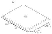
도 1에는 일반적인 배터리 모듈에서 단위 셀을 구성하는 파우치형 배터리 셀의 사시도가 도시되어 있다. 1 is a perspective view of a pouch-type battery cell constituting a unit cell in a typical battery module.
도 1에 도시된 배터리 셀(110)은 셀 리드(112)가 일측 단부에 형성되어 있는 판상형 단방향 배터리 셀이다. 구체적으로 배터리 셀(110)은 금속층과 수지층을 포함하는 라미네이트 시트의 파우치형 케이스(120)에 전극조립체(105)를 내장하고, 예를 들어, 열융착에 의해 실링부(SP)를 형성한 구조이다. 셀 리드(112) 중에서 양의 극성(+)을 띠는 것은 전극조립체(105) 안의 양극판에 연결되어 있고 셀 리드(112) 중에서 음의 극성(-)을 띠는 것은 전극조립체(105) 안의 음극판에 연결되어 있다.The
배터리 모듈의 단위 셀은 이러한 배터리 셀(110) 하나 또는 이러한 배터리 셀(110) 두 개 이상을 직렬이나 병렬로 연결한 것이 될 수 있다. 도 2는 예를 들어 배터리 셀(110) 3개를 병렬로 연결한 3P 뱅크 단위 셀의 측면도이다. The unit cell of the battery module may be a
도 2를 참조하면, 배터리 셀(110)은 수평으로 눕혀져 동일 극성의 셀 리드(112)가 위 아래로 놓이도록 지면에서부터 높이 방향으로 적층된 후 위 아래로 놓인 셀 리드(112)끼리 통합된다. 하나의 단위 셀(200)에서 셀 리드(112)는 일측에 노출된 상태가 된다. Referring to FIG. 2, the
보통 이러한 단위 셀(200)은 수직 적층 구조의 배터리 모듈로 제조된다. 수직 적층 구조의 배터리 모듈에서는 단위 셀(200)이 수직으로 세워져 셀 리드(112)가 일측에 모아지도록 나란히 적층된 후 하나의 ICB(Interconnect Board) 조립체와 결합된다. ICB 조립체는 ICB 프레임에 버스바를 구비한 것으로, 셀 리드(112)를 연결하여 단위 셀(200)의 전기적 연결을 달성하는 한편, 배터리 셀(110)의 반복적인 충전 및 방전 동안에 배터리 셀(110)의 온도에 대응되는 전기 신호 그리고 배터리 셀(110)의 전류 또는 전압에 대응되는 전기 신호를 배터리 관리 시스템(BMS)에 전달하는 용도로 사용된다. 그런데 이러한 단위 셀(200)을 수평으로 눕혀 두 단위 셀(200)끼리 셀 리드(112)가 서로 마주보도록 적층하는 수평 적층 구조의 배터리 모듈에 대해서는 상술한 수직 적층 구조의 배터리 모듈 제조 방법과 ICB 조립체를 그대로 적용하기 어려운 문제가 있다. Usually, the
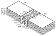
도 3은 도 2의 단위 셀(200) 8개를 이용한 수평 적층 구조의 배터리 모듈의 일 예를 도시한다. 3 shows an example of a battery module having a horizontal stacked structure using eight
도 3을 참조하면, 단위 셀(200)을 수평으로 눕혀 지면에서부터 높이 방향으로 4개 적층한 배터리 셀 조립체(230) 두 개를 서로의 셀 리드(112)가 대향하도록 마주 보게 연결하여 배터리 모듈(250)을 제조하려는 구조가 도시되어 있다. 그런데, 두 배터리 셀 조립체(230) 간에 셀 리드(112)가 서로 마주보는 구조로 인하여, 단위 셀(200) 측면에서의 용접이 어렵고 단위 셀(200) 상면에서 용접을 해야 한다. 상면 용접을 하려면, 두 개의 배터리 셀 조립체(230)를 먼저 만들어 이들 사이를 용접할 수는 없고, 우선 두 개의 단위 셀(200)이 마주보도록 놓은 후 상면에서 셀 리드(112)간 용접(제1층), 그 위에 두 단위 셀(200)을 마주보도록 적층 후 상면에서 셀 리드(112)간 용접(제2층), 다시 그 위에 두 단위 셀(200)을 마주보도록 적층 후 상면에서 셀 리드(112)간 용접(제3층)하는 등의 순서대로, 적층과 용접을 순차적으로 반복하면서 지면에서부터 높이 방향으로, 즉 아래에서부터 위로 단위 셀(200)을 조립해 나가야 한다.Referring to FIG. 3, the battery modules (eg, the battery modules) are connected to two
이처럼 수평 적층 구조의 배터리 모듈(250)에서는 제조 공정이 매우 복잡해지는 문제가 있다. 뿐만 아니라, Hv 터미널(Hv 양극/음극)의 방향이 수평 적층 구조의 배터리 모듈(250) 상단에 위치해야 하는 경우이면 전기적 연결을 구성하기가 매우 까다로워지는 문제도 있다. In this way, in the
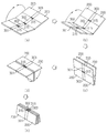
도 4와 도 5는 도 3과 같은 배터리 모듈(250)에서 생각해 볼 수 있는 단위 셀(200)의 배열을 보여주기 위한 것으로, 각 도에서 (a)는 배터리 모듈(250)을 상면에서 본 모습이고 (b), (c는 배터리 모듈(250)을 측면에서 본 모습이다. 여러 가지 배열 중에서도 도 4와 도 5는 특히 8개의 단위 셀(200)을 서로 직렬연결시킬 수 있는 경우를 도시한 것이다. 4 and 5 are for showing the arrangement of the
먼저 도 4는 서로 마주보는 단위 셀(200)의 앞면이 모두 위로 오게 하여 적층하는 경우로서, (a)를 참조하면 서로 마주보는 단위 셀(200)의 앞면이 위로 오게 놓여 있다. 이 때 (b)와 같이 위 아래로 놓이는 단위 셀(200)의 셀 리드(112)가 서로 반대 극성으로 되도록 교번되게 하거나(옵션 1), (c)와 같이 위 아래로 놓이는 단위 셀(200)의 셀 리드(112)가 동일한 극성이 되게 하는 방법(옵션 2)이 가능하다. First, FIG. 4 is a case where the front surfaces of the
다음으로 도 5는 서로 마주보는 단위 셀(200) 중 하나는 뒷면이 위로 오게 하고 다른 하나는 앞면이 위로 오게 하여 적층하는 로서, (a)를 참조하면 서로 마주보는 단위 셀(200) 중 좌측의 단위 셀(200)은 뒷면이 위로 오고 우측의 단위 셀(200)은 앞면이 위로 오게 놓여 있다. 이 때에는 (b)와 같이 위 아래로 놓이는 단위 셀(200)의 셀 리드(112)가 동일한 극성이 되게 하거나(옵션 3), (c)와 같이 위 아래로 놓이는 단위 셀(200)의 셀 리드(112)가 서로 반대 극성으로 되도록 교번되게 하는 방법이 가능하다(옵션 4). Next, FIG. 5 shows that one of the
이처럼, 수평 적층 구조의 배터리 모듈(250)에서 8개의 단위 셀(200)을 직렬연결하기 위해 배열하는 방법에만도 옵션 1 내지 옵션 4와 같이 경우의 수가 발생되고, 특히 Hv 터미널의 방향이 배터리 모듈(250) 상단에 위치해야 하는 경우이면 그 위치까지 고려하여 전기적 연결을 구성해야 하므로 더 어려워진다. 그리고, 예시한 직렬연결 이외에 다른 직/병렬연결을 한다면 그 종류에 따라 전기적 연결 구조는 복잡해진다. 특히 전기적 연결을 구성하기 위해 각 단위 셀(200)의 셀 리드(112) 사이를 연결할 때에 그 경우의 수가 무수히 많아진다. 따라서, 무수히 많은 경우의 수 중에서 가장 단순하면서도 가장 간단한 연결 공법으로 배터리 모듈을 제조하는 방법, 그리고 그 방법의 수행에 필요한 ICB 조립체가 필요하다. As described above, the number of cases occurs as in options 1 to 4 only in a method of arranging 8
본 발명은 상기와 같은 문제점을 해결하기 위해 창안된 것으로서, 본 발명이 해결하고자 하는 과제는, 단방향 배터리 셀이 서로의 셀 리드끼리 대향하면서 마주보게 놓여 적층되는 수평 적층 구조의 배터리 모듈에 적합한 ICB 조립체, 이를 포함한 배터리 모듈, 그리고 그 제조 방법을 제공하는 것이다.The present invention was created to solve the above problems, and the problem to be solved by the present invention is an ICB assembly suitable for a battery module of a horizontal stacked structure in which unidirectional battery cells are stacked facing each other while facing each other cell leads. , To provide a battery module including the same, and a method of manufacturing the same.
본 발명의 다른 목적 및 장점들은 하기의 설명에 의해서 이해될 수 있으며, 본 발명의 실시예에 의해 보다 분명하게 알게 될 것이다. 또한, 본 발명의 목적 및 장점들은 청구범위에 나타낸 수단 및 그 조합에 의해 실현될 수 있음을 쉽게 알 수 있을 것이다.Other objects and advantages of the present invention can be understood by the following description, and will be more clearly understood by examples of the present invention. In addition, it will be readily appreciated that the objects and advantages of the present invention can be realized by means of the appended claims and combinations thereof.
상기 목적을 달성하기 위한 본 발명에 따른 ICB 조립체는, 셀 리드가 일측 단부에 형성되어 있는 단방향 배터리 셀이 서로의 셀 리드끼리 대향하면서 마주보게 놓이도록 상기 셀 리드를 수용하는 ICB 프레임; 및 상기 ICB 프레임에 조립되어 상기 셀 리드와 전기적 연결되는 버스바를 포함한다.An ICB assembly according to the present invention for achieving the above object includes: an ICB frame for accommodating the cell leads such that the unidirectional battery cells in which the cell leads are formed at one end are placed facing each other with the cell leads facing each other; And a bus bar assembled to the ICB frame and electrically connected to the cell lead.
상기 ICB 프레임은 여러 가지 모양의 버스바를 차등 적용할 수 있도록 형성되어 있다. The ICB frame is formed to differentially apply various types of bus bars.
바람직하게, 상기 ICB 프레임에는 상기 셀 리드 중 어느 하나의 셀 리드와 연결되는 버스바 및 상기 셀 리드 중 서로 대향하는 셀 리드끼리를 연결하는 버스바 중 적어도 어느 하나가 임의의 위치에 조립될 수 있도록 하는 여러 개의 단차와 버스바 삽입홀이 형성되어 있다.Preferably, in the ICB frame, at least one of a bus bar connected to any one of the cell leads and a bus bar connecting mutually opposite cell leads among the cell leads can be assembled at an arbitrary position. There are several steps and a bus bar insertion hole.
그리고, 상기 버스바는 상기 단차와 버스바 삽입홀을 통해 상기 ICB 프레임에 조립될 수 있는 여러 가지 모양의 버스바로 이루어진 군에서 상기 배터리 셀간의 전기적 연결 관계를 고려하여 선택한 버스바의 조합이다. In addition, the bus bar is a combination of bus bars selected in consideration of the electrical connection between the battery cells in the group consisting of various shapes of bus bars that can be assembled to the ICB frame through the step and the bus bar insertion holes.
일 실시예에서, 상기 ICB 프레임은 길이와 너비를 갖는 판상 구조물이고, 상기 길이 방향 중심선을 기준으로 양측으로 상기 배터리 셀이 서로 마주보며 놓이도록 상기 배터리 셀의 셀 리드를 놓을 수 있는 셀 리드 안착부, Hv 터미널 안착부 및 버스바 삽입홀을 포함한다. In one embodiment, the ICB frame is a plate-like structure having a length and a width, and a cell lead seating unit capable of placing cell leads of the battery cells such that the battery cells face each other on both sides of the longitudinal center line. , Hv terminal seating part and bus bar insertion hole.
상기 버스바는 상기 셀 리드 안착부에 탈착 가능하게 조립될 수 있다. The bus bar may be detachably assembled to the cell lead seat.
상기 셀 리드 안착부는 상기 ICB 프레임의 상기 길이 방향 제1 및 제2 측변을 따라 두 군데씩 양측으로 형성이 되어 있어, 상기 제1 측변을 따라 제1 셀 리드 안착부와 제3 셀 리드 안착부가 형성되고 상기 제2 측변을 따라 상기 제1 셀 리드 안착부와 마주보는 제2 셀 리드 안착부, 상기 제3 셀 리드 안착부와 마주보는 제4 셀 리드 안착부를 포함하고, 상기 Hv 터미널 안착부는 상기 제1 및 제2 측변에 수직인 상기 너비 방향 제3 및 제4 측변 쪽에 각각 형성이 되어 있어, 상기 제3 측변 쪽의 제1 Hv 터미널 안착부와 상기 제4 측변 쪽의 제2 Hv 터미널 안착부를 포함할 수 있다. The cell lead seating portion is formed on both sides along the first and second side edges in the longitudinal direction of the ICB frame, so that the first cell lead seating portion and the third cell lead seating portion are formed along the first side edge. And a second cell lead seating part facing the first cell lead seating part along the second side, a fourth cell lead seating part facing the third cell lead seating part, and the Hv terminal seating part It is formed on the third and fourth side sides in the width direction perpendicular to the first and second side sides, and includes a first Hv terminal seating portion on the third side side and a second Hv terminal seating portion on the fourth side side. can do.
상기 버스바 삽입홀은 상기 제3 측변으로부터 상기 제1 셀 리드 안착부 쪽으로 버스바를 삽입하도록 하는 제1 버스바 삽입홀과, 상기 제3 측변으로부터 상기 제2 셀 리드 안착부 쪽으로 다른 버스바를 삽입하도록 하는 제2 버스바 삽입홀과, 상기 너비 방향과 나란하게 상기 ICB 프레임을 관통하여 형성되어 상기 제3 및 제4 셀 리드 안착부에 동시에 놓이는 또 다른 버스바를 삽입하도록 하는 관통 버스바 삽입홀을 포함할 수 있다. The bus bar insertion hole is a first bus bar insertion hole for inserting a bus bar from the third side toward the first cell lead seating part, and another bus bar from the third side toward the second cell lead seating part. And a second busbar insertion hole, and a through-busbar insertion hole formed through the ICB frame in parallel with the width direction to insert another busbar placed at the same time on the third and fourth cell lead seats. can do.
일 실시예에 있어서, 한 종류의 ICB 조립체에서는, 상기 버스바가 상기 제1 Hv 터미널 안착부에 놓이는 부분과 상기 제2 셀 리드 안착부에 놓이는 부분을 포함하는 Hv 터미널 버스바와, 상기 제1 셀 리드 안착부에 놓이는 연결용 버스바와, 상기 제3 및 제4 셀 리드 안착부 위에 동시에 놓이는 관통 버스바를 포함한다. 상기 Hv 터미널 버스바는 상기 제2 버스바 삽입홀에 끼워 조립되고, 상기 연결용 버스바는 상기 제1 버스바 삽입홀에 끼워 조립되며, 상기 관통 버스바는 상기 관통 버스바 삽입홀에 끼워 조립된다.In one embodiment, in one type of ICB assembly, an Hv terminal busbar including a portion where the busbar is placed on the first Hv terminal seating portion and a portion placed on the second cell lead seating portion, and the first cell lead It includes a connecting bus bar that is placed on the seating portion, and a through bus bar that is simultaneously placed on the third and fourth cell lead seating portions. The Hv terminal bus bar is fitted into the second bus bar insertion hole, the connecting bus bar is assembled into the first bus bar insertion hole, and the through bus bar is inserted into the through bus bar insertion hole and assembled do.
일 실시예에 있어서, 다른 종류의 ICB 조립체에서는, 상기 버스바가 상기 제1 셀 리드 안착부에 놓이는 연결용 버스바와, 상기 제2 셀 리드 안착부에 놓이는 다른 연결용 버스바와, 상기 제3 및 제4 셀 리드 안착부 위에 동시에 놓이는 관통 버스바를 포함한다. 상기 연결용 버스바는 상기 제1 버스바 삽입홀에 끼워 조립되고, 상기 다른 연결용 버스바는 상기 제2 버스바 삽입홀에 끼워 조립되며, 상기 관통 버스바는 상기 관통 버스바 삽입홀에 끼워 조립된다.In one embodiment, in another type of ICB assembly, the bus bar for connecting the bus bar is placed on the first cell lead seating portion, the other connecting bus bar for the second cell lead seating portion, and the third and third Includes a through busbar that is simultaneously placed over the four cell lid seats. The connecting bus bar is fitted into the first bus bar insertion hole, and the other connecting bus bar is assembled into the second bus bar insertion hole, and the through bus bar is inserted into the through bus bar insertion hole. Is assembled.
일 실시예에 있어서, 또 다른 종류의 ICB 조립체에서는, 상기 버스바가 상기 제2 Hv 터미널 안착부에 놓이는 부분과 상기 제1 셀 리드 안착부에 놓이는 부분을 포함하는 Hv 연장 버스바와, 상기 제2 셀 리드 안착부에 놓이는 연결용 버스바와, 상기 제3 및 제4 셀 리드 안착부 위에 동시에 놓이는 관통 버스바를 포함한다. 상기 Hv 연장 버스바는 상기 제2 Hv 터미널 안착부와 상기 제1 셀 리드 안착부에 놓여 조립되고, 상기 연결용 버스바는 상기 제2 버스바 삽입홀에 끼워 조립되며, 상기 관통 버스바는 상기 관통 버스바 삽입홀에 끼워 조립된다.In one embodiment, in another type of ICB assembly, an Hv extension busbar including a portion where the busbar is placed on the second Hv terminal seat and a portion placed on the first cell lead seat, and the second cell It includes a connecting bus bar that is placed on the lead seat, and a through bus bar that is simultaneously placed on the third and fourth cell lead seats. The Hv extension bus bar is placed and assembled on the second Hv terminal seating portion and the first cell lead seating portion, and the connecting bus bar is fitted into the second bus bar insertion hole, and the through bus bar is the It is assembled by inserting it into the through-hole of the busbar.
바람직하게, 상기 ICB 조립체는 상기 ICB 프레임의 길이 방향으로 다른 ICB 프레임에 힌지 구조로 연결된다. Preferably, the ICB assembly is hinged to another ICB frame in the longitudinal direction of the ICB frame.
예를 들어, 상기 ICB 프레임의 측면에는 봉 형상 돌출부가 형성되어 있고, 길이 방향을 따라 나열된 두 ICB 프레임의 측면 사이에 상기 돌출부에 끼워지는 홈을 구비한 조인트 부재로 연결될 수 있다. For example, a rod-shaped protrusion is formed on a side surface of the ICB frame, and may be connected to a joint member having a groove fitted between the protrusions between the side surfaces of two ICB frames arranged along the length direction.
상기 ICB 프레임 하나에는 상기 배터리 셀이 2개 놓일 수 있다. 그러면, 상기 버스바는 상기 ICB 프레임의 상면에 조립된다.Two battery cells may be placed in one ICB frame. Then, the bus bar is assembled on the upper surface of the ICB frame.
본 발명에 따른 배터리 모듈 제조 방법은 본 발명에 따른 ICB 조립체를 이용하여 수행된다. The battery module manufacturing method according to the present invention is performed using the ICB assembly according to the present invention.
본 발명에 따른 배터리 모듈 제조 방법은 (a) 셀 리드가 일측 단부에 형성되어 있는 단방향 배터리 셀이 서로의 셀 리드끼리 대향하면서 마주보게 놓이도록 상기 셀 리드를 수용하는 ICB 프레임; 및 상기 ICB 프레임에 조립되어 상기 셀 리드와 전기적 연결되는 버스바를 포함하는 ICB 조립체를 준비하되, 동일한 모양의 ICB 프레임에 버스바만 바꿔 끼워 차등 적용해 여러 가지 ICB 조립체를 준비하는 단계; (b) 상기 ICB 조립체의 상기 ICB 프레임을 힌지 구조로 측면 연결하여 상기 ICB 프레임 길이 방향으로 나열하는 단계; (c) 측면 연결된 ICB 프레임 길이 방향 좌우측에 상기 배터리 셀을 안착시켜 상기 배터리 셀이 서로 마주보도록 평면 상에 나열하되, 상기 버스바 위로 상기 셀 리드를 안착시켜 상기 배터리 셀을 평면 나열하는 단계; (d) 나열된 배터리 셀에 대해 상면에서 상기 버스바와 셀 리드를 일괄 용접하여 상기 ICB 조립체와 상기 배터리 셀을 연결하는 단계; (e) 나열된 상기 ICB 프레임을 상기 힌지 부분에서 접어서 상기 배터리 셀을 적층하는 단계; 및 (f) 상기 ICB 프레임에서 측면으로 노출되어 있는 버스바 사이에 추가 버스바를 결합하는 단계를 포함할 수 있다.A battery module manufacturing method according to the present invention includes: (a) an ICB frame for accommodating the cell leads such that the unidirectional battery cells in which the cell leads are formed at one end are placed facing each other; And preparing an ICB assembly including a bus bar assembled to the ICB frame and electrically connected to the cell lead, but preparing various ICB assemblies by differentially applying only the bus bar to the same shape ICB frame; (b) side-by-side connecting the ICB frames of the ICB assembly with a hinge structure to arrange the ICB frames in the longitudinal direction; (c) placing the battery cells on the left and right sides of an ICB frame connected to the side in a horizontal direction to arrange the battery cells facing each other, and placing the cell leads on the bus bar to planarly arrange the battery cells; (d) connecting the ICB assembly and the battery cell by collectively welding the bus bar and the cell lead on the upper surface of the listed battery cells; (e) folding the ICB frames listed at the hinge portion to stack the battery cells; And (f) coupling an additional busbar between the busbars that are exposed laterally in the ICB frame.
본 발명에 따른 배터리 모듈은 본 발명에 따른 ICB 조립체를 포함한다. The battery module according to the invention comprises the ICB assembly according to the invention.
본 발명에 따른 배터리 모듈은, 셀 리드가 일측 단부에 형성되어 있는 단방향 배터리 셀이 서로의 셀 리드끼리 대향하면서 마주보게 놓이도록 ICB 조립체를 가운데에 두고 서로 마주보면서 연결된 배터리 셀 - ICB 조립체 - 배터리 셀의 단위가 지면에서 높이 방향으로 적층된 배터리 모듈이고, 각 ICB 조립체는 상기 셀 리드를 수용하는 ICB 프레임; 및 상기 ICB 프레임에 조립되어 상기 셀 리드와 전기적 연결되는 버스바를 포함하며, 적층된 ICB 조립체 사이는 조인트 부재로 연결되어 있고, 적층된 ICB 조립체 측면에서는 상기 배터리 셀의 상하 직렬연결을 위한 추가 버스바가 결합되어 있으며, 상기 각 ICB 조립체의 ICB 프레임은 서로 동일한 모양이고 버스바만 바꿔 끼워 차등 적용한 여러 가지 종류의 ICB 조립체인 것이다. The battery module according to the present invention, the battery cells connected to each other with the ICB assembly centered so that the unidirectional battery cells in which the cell leads are formed at one end are placed facing each other with the cell leads facing each other-ICB assembly-battery cell The unit of the battery module is stacked in the height direction from the ground, each ICB assembly is an ICB frame for receiving the cell lead; And a bus bar assembled to the ICB frame and electrically connected to the cell lead, connected between the stacked ICB assemblies with a joint member, and on the side of the stacked ICB assembly there is an additional bus bar for vertical connection of the battery cells. Combined, the ICB frames of each ICB assembly have the same shape and are various types of ICB assemblies that are differentially applied by swapping only busbars.
상기 배터리 셀은 동일 극성의 셀 리드가 서로 접하면서 병렬연결되도록 적층되어 있는 뱅크 단위 셀인 것이 바람직하다. The battery cells are preferably bank unit cells stacked such that cell leads of the same polarity are connected in parallel while contacting each other.
그리고 서로 마주보는 두 배터리 셀 사이는 상기 ICB 조립체에 조립된 버스바를 통해 평면상에서 직렬연결되어 있을 수 있다. And between the two battery cells facing each other may be connected in series on a plane through a bus bar assembled to the ICB assembly.
본 발명에 따르면, 셀 리드가 일측 단부에 형성되어 있는 단방향 배터리 셀이 서로의 셀 리드끼리 대향하면서 서로 마주보게 수평 적층된 구조의 배터리 모듈에 적합한 ICB 조립체와 이를 이용한 배터리 모듈 제조 방법이 제공된다. According to the present invention, there is provided an ICB assembly suitable for a battery module having a horizontally stacked structure and a battery module manufacturing method using the unidirectional battery cells in which the cell leads are formed at one end, facing each other while facing each other.
본 발명의 ICB 조립체는 셀 리드가 일측 단부에 형성되어 있는 단방향 배터리 셀이 서로의 셀 리드끼리 대향하면서 마주보게 놓이도록 한다. 따라서, 단방향 배터리 셀의 수평 적층 + 단방향 배터리 셀이 마주보는 구조의 배터리 모듈 제작에 편리하게 이용할 수 있다. 본 발명의 ICB 조립체는 기존 수직 적층 구조의 배터리 모듈에 이용되는 ICB 조립체와는 차별화된다. In the ICB assembly of the present invention, the unidirectional battery cells in which the cell leads are formed at one end are placed facing each other while the cell leads face each other. Accordingly, horizontal stacking of unidirectional battery cells + unidirectional battery cells can be conveniently used for manufacturing a battery module having a structure facing each other. The ICB assembly of the present invention is different from the ICB assembly used in the battery module of the conventional vertical stack structure.
본 발명의 ICB 조립체에 따르면, 동일한 ICB 프레임에 여러 가지 모양의 버스바를 차등 적용하여 조립할 수 있다. 보다 자유로운 구성의 전기적 연결이 가능해지는 효과가 있다. According to the ICB assembly of the present invention, various shapes of bus bars can be differentially applied to the same ICB frame and assembled. It has the effect of enabling a more flexible electrical connection.
본 발명의 일 구성에 따라, ICB 프레임에 다양한 종류의 버스바를 임의의 위치에 조립할 수 있는 여러 개의 단차와 버스바 삽입홀을 형성해 두면, 단차와 버스바 삽입홀의 임의의 조합을 택하여 원하는 위치에 원하는 모양의 버스바를 조립할 수 있게 된다. 버스바는 ICB 프레임에 형성한 단차와 버스바 삽입홀을 통해 ICB 프레임에 조립될 수 있는 여러 가지 모양의 버스바로 이루어진 군으로 구비해 둘 수 있고, 그 중에서 원하는 전기적 연결 관계를 고려하여 선택한 버스바를 다양하게 조합하여 ICB 프레임에 조립할 수 있다. 따라서, 하나의 ICB 프레임 모양을 정해두면 버스바만 바꿔 끼면서 이 ICB 프레임을 여러 가지 전기적 연결에 사용할 수 있게 된다. 따라서, 본 발명의 ICB 조립체는 범용, 다목적, 다용도이다. According to one configuration of the present invention, if a plurality of steps and busbar insertion holes capable of assembling various types of busbars at arbitrary positions are formed in the ICB frame, an arbitrary combination of steps and busbar insertion holes is selected and placed at a desired position. You will be able to assemble the desired shape of the busbar. The busbar can be provided as a group of busbars of various shapes that can be assembled to the ICB frame through the steps formed in the ICB frame and the busbar insertion hole, and among them, the busbar selected by considering the desired electrical connection relationship It can be assembled into ICB frames in various combinations. Therefore, if the shape of one ICB frame is determined, the ICB frame can be used for various electrical connections while changing only the bus bar. Therefore, the ICB assembly of the present invention is universal, versatile, and versatile.
본 발명의 ICB 조립체를 이용하면 다수의 배터리 셀을 평면에 나열하여 일괄 용접하고 접어서 적층해 배터리 모듈을 제조할 수 있다. 특히 본 발명의 배터리 모듈 제조 방법에 따르면, 단방향 배터리 셀을 수평 적층하고 단방향 배터리 셀이 서로 마주보는 구조의 배터리 모듈 제조 단계가 매우 간단해진다. Using the ICB assembly of the present invention, it is possible to manufacture a battery module by stacking, folding and stacking a plurality of battery cells on a plane. In particular, according to the method for manufacturing a battery module of the present invention, the steps of manufacturing a battery module having a structure in which unidirectional battery cells are horizontally stacked and unidirectional battery cells face each other are greatly simplified.
종래에는 배터리 셀 적층과 셀 리드 용접으로 된 단계를 순차적으로 여러 번 반복해야만 수평 적층 구조의 배터리 모듈을 제조할 수 있지만, 본 발명의 배터리 모듈 제조 방법에 따르면, 배터리 셀을 한 번에 용접하고 한 번에 접어 적층하는 것이 가능하여 대량 생산에 매우 적합하다. 또한, 본 발명에 따르면, 배터리 셀의 적층 전, 셀 리드-버스바의 용접 및 센싱 와이어의 접합을 한 번에 완료할 수 있는 장점도 있다. In the related art, a battery module having a horizontal stacked structure can be manufactured only by sequentially repeating the steps of battery cell stacking and cell lead welding, but according to the battery module manufacturing method of the present invention, a battery cell is welded at a time. It can be folded and stacked at once, making it very suitable for mass production. In addition, according to the present invention, it is also possible to complete the welding of the cell lead-bus bar and the bonding of the sensing wires at one time before the battery cells are stacked.
본 발명의 배터리 모듈은 본 발명의 ICB 조립체를 포함함으로써 조립이 매우 용이하다. 그리고, 배터리 셀 - ICB 조립체 - 배터리 셀의 단위를 추가로 더 포함시키는 간단한 과정을 통해 직렬연결되는 배터리 셀 개수를 증가시킬 수 있어 배터리 모듈의 확장이 얼마든지 가능하다는 장점이 있다. The battery module of the present invention is very easy to assemble by including the ICB assembly of the present invention. In addition, the number of battery cells connected in series can be increased through a simple process of further including a unit of a battery cell-an ICB assembly-a battery cell, and thus an extension of the battery module is possible.
본 발명에 따르면, 배터리 모듈을 구성하는 다수의 배터리 셀 사이의 무수히 많은 전기적 연결 관계의 경우의 수 중에서 가장 단순하며, 공법이 간단한 연결을 제공할 수 있다. 배터리 셀 적층을 위한 적층 가이드로는 힌지 구조가 적용될 수 있으며, ICB 조립체 사이의 전기적 연결은 ICB 프레임 측면에 추가 버스바를 결합하여 달성할 수 있다. According to the present invention, it is the simplest of the number of cases of a myriad of electrical connection relationships between a plurality of battery cells constituting a battery module, and a simple construction method can be provided. As a stacking guide for stacking battery cells, a hinge structure may be applied, and electrical connection between ICB assemblies may be achieved by combining an additional busbar on the side of the ICB frame.
본 명세서에 첨부되는 다음의 도면들은 본 발명의 바람직한 실시예를 예시하는 것이며, 후술하는 발명의 상세한 설명과 함께 본 발명의 기술사상을 더욱 이해시키는 역할을 하는 것이므로, 본 발명은 그러한 도면에 기재된 사항에만 한정되어 해석되어서는 아니 된다.
도 1은 종래 배터리 모듈에서 단위 셀을 구성하는 배터리 셀의 사시도이다.
도 2는 종래 배터리 모듈에 포함될 수 있는 단위 셀의 측면도이다.
도 3은 도 2의 단위 셀을 포함하는 수평 적층 구조의 배터리 모듈의 일 예를 도시한다.
도 4 및 도 5는 수평 적층 구조의 배터리 모듈에서 단위 셀의 다양한 배열 방법을 보여주기 위한 것이다.
도 6은 본 발명의 일 실시예에 따른 3P8S 배터리 모듈의 전기적 연결 관계를 도시한 것이다.
도 7은 본 발명의 일 실시예에 따른 ICB 프레임의 사시도이다.
도 8 내지 도 10은 본 발명의 일 실시예에 따른 ICB 조립체들의 사시도이다.
도 11은 본 발명의 일 실시예에 따른 ICB 조립체들의 연결 방법을 설명하기 위한 도면이다.
도 12는 ICB 조립체들의 연결에 이용될 수 있는 조인트 부재의 사시도이다.
도 13은 도 12의 조인트 부재를 이용해 ICB 조립체들이 연결된 상태를 도시한다.
도 14는 도 8 내지 도 10의 ICB 조립체들을 4개 측면 연결해 나열한 상태를 도시한다.
도 15는 본 발명의 일 실시예에 따른 배터리 모듈 제조 방법에서 단위 셀 안착 단계 및 상면 용접 단계를 설명하기 위한 도면이다.
도 16은 본 발명의 일 실시예에 따른 배터리 모듈 제조 방법에서 병풍식 접철 방식으로 단위 셀을 적층하는 단계를 설명하기 위한 도면이다.
도 17은 도 16의 방법에 따라 단위 셀이 적층되어진 상태의 사시도이다.
도 18은 본 발명의 일 실시예에 따른 배터리 모듈 제조 방법에서 단위 셀의 직렬연결을 완성하기 위해 추가로 필요한 추가 버스바를 결합하는 단계를 설명하기 위한 도면이다. The following drawings attached to this specification are intended to illustrate preferred embodiments of the present invention, and serve to further understand the technical idea of the present invention together with the detailed description of the invention described below, and thus the present invention is described in such drawings. It is not limited to interpretation.
1 is a perspective view of a battery cell constituting a unit cell in a conventional battery module.
2 is a side view of a unit cell that may be included in a conventional battery module.
3 illustrates an example of a battery module having a horizontal stacked structure including the unit cell of FIG. 2.
4 and 5 are for showing various arrangement methods of the unit cells in the battery module of the horizontal stacked structure.
Figure 6 shows the electrical connection of the 3P8S battery module according to an embodiment of the present invention.
7 is a perspective view of an ICB frame according to an embodiment of the present invention.
8 to 10 are perspective views of ICB assemblies according to an embodiment of the present invention.
11 is a view for explaining a method of connecting ICB assemblies according to an embodiment of the present invention.
12 is a perspective view of a joint member that can be used to connect ICB assemblies.
FIG. 13 shows the ICB assemblies connected using the joint member of FIG. 12.
FIG. 14 shows a state in which the ICB assemblies of FIGS. 8 to 10 are connected by four sides.
15 is a view for explaining a unit cell seating step and the upper surface welding step in the battery module manufacturing method according to an embodiment of the present invention.
16 is a view for explaining the step of stacking the unit cells in a folding screen folding method in the battery module manufacturing method according to an embodiment of the present invention.
17 is a perspective view of a unit cell stacked according to the method of FIG. 16.
18 is a view for explaining a step of coupling an additional bus bar additionally required to complete the serial connection of the unit cell in the battery module manufacturing method according to an embodiment of the present invention.
이하, 첨부된 도면을 참조하여 본 발명의 바람직한 실시예를 상세히 설명하기로 한다. 다만, 본 발명에 따른 실시예는 여러 가지 다른 형태로 변형될 수 있으며, 본 발명의 범위가 아래의 실시예로 한정되는 것으로 해석되어서는 안 된다. 본 발명의 실시예는 당업계에서 평균적인 지식을 가진 자에게 본 발명을 보다 완전하게 설명하기 위해서 제공되는 것이다. Hereinafter, preferred embodiments of the present invention will be described in detail with reference to the accompanying drawings. However, the embodiment according to the present invention may be modified in various other forms, and the scope of the present invention should not be interpreted as being limited to the following examples. The embodiments of the present invention are provided to more fully describe the present invention to those skilled in the art.
본 명세서 및 청구범위에 사용된 용어나 단어는 통상적이거나 사전적인 의미로 한정해서 해석되어서는 아니되며, 발명자는 그 자신의 발명을 가장 최선의 방법으로 설명하기 위해 용어의 개념을 적절하게 정의할 수 있다는 원칙에 입각하여 본 발명의 기술적 사상에 부합하는 의미와 개념으로 해석되어야만 한다.The terms or words used in the present specification and claims should not be interpreted as being limited to ordinary or lexical meanings, and the inventor can appropriately define the concept of terms in order to best describe his or her invention. Based on the principle that it should be interpreted as meanings and concepts consistent with the technical spirit of the present invention.
따라서, 본 명세서에 기재된 실시예와 도면에 도시된 구성은 본 발명의 가장 바람직한 일 실시예에 불과할 뿐이고 본 발명의 기술적 사상에 모두 대변하는 것은 아니므로, 본 출원시점에 있어서 이들을 대체할 수 있는 다양한 균등물과 변형예들이 있을 수 있음을 이해하여야 한다. Therefore, the embodiments shown in the embodiments and the drawings described in this specification are only the most preferred embodiments of the present invention and do not represent all of the technical spirit of the present invention. It should be understood that there may be equivalents and variations.
본 발명에서는 조립이 용이하고, 간단한 과정으로 확장이 가능한 배터리 모듈 제조에 이용될 수 있는 부품, 그리고 이를 이용한 배터리 모듈 및 그 제조 방법을 제공한다. 특히 본 발명은 단방향 배터리 셀의 수평 적층 + 단방향 배터리 셀이 마주보는 구조의 배터리 모듈에 적합한 신규 ICB 조립체에 관한 것이다. 이를 이용하면 일괄 용접, 일괄 적층이 가능한 신규 배터리 모듈 제조 방법이 제공된다. 또한, 이를 이용하면 간단한 과정으로 확장이 가능한 배터리 모듈이 제공한다. The present invention provides a component that can be used for manufacturing a battery module that is easy to assemble and can be extended by a simple process, and a battery module and a manufacturing method using the same. In particular, the present invention relates to a new ICB assembly suitable for a horizontal stacking of unidirectional battery cells + a battery module having a structure in which unidirectional battery cells face each other. Using this, a method for manufacturing a new battery module capable of batch welding and batch lamination is provided. In addition, using this provides a battery module that can be extended by a simple process.
신규 ICB 조립체는 ICB 프레임에 전기적 연결을 위한 다양한 모양의 버스바가 조립될 수 있는 것이다. 전기적 연결 관계에 따라서는 여러 개의 ICB 프레임을 이용할 수 있다. 이 때 각 ICB 프레임의 구조는 동일하나, 전기적 연결에 맞는 모양의 버스바를 차등 이용하면 된다. In the new ICB assembly, various shapes of busbars for electrical connection to the ICB frame can be assembled. Several ICB frames can be used depending on the electrical connection relationship. At this time, the structure of each ICB frame is the same, but a bus bar of a shape suitable for electrical connection may be used differentially.
이처럼 본 발명은 동일한 구조의 ICB 프레임에, 다른 모양의 버스바를 적용하여, 전기적 연결 관계를 쉽게 구현하도록 하는 데에 가장 큰 특징이 있다. As described above, the present invention has the greatest feature to make it easy to implement an electrical connection relationship by applying different shapes of busbars to the ICB frame of the same structure.
이하의 실시예에서는 예컨대 3P8S 배터리 모듈을 설명함으로써 본 발명에 관하여 설명한다. 그러나 본 발명이 여기에 한정되는 것은 아니다. 병렬연결의 증가가 필요할 경우에는 단위 셀 뱅크 내의 배터리 셀 개수를 증가시키면 된다. 배터리 셀 개수 증가에 의해 단위 셀이 두꺼워져서 ICB 조립체를 이용한 적층이 공간적으로 원활하지 않을 경우에는, 스페이서를 조립하여 해결할 수 있다. In the following embodiments, for example, the present invention will be described by describing a 3P8S battery module. However, the present invention is not limited to this. If an increase in parallel connection is required, the number of battery cells in the unit cell bank can be increased. If the stacking using the ICB assembly is not spatially smooth due to the increase in the number of battery cells, the spacer can be solved by assembling the spacer.
직렬연결의 증가가 필요할 경우, 단위 셀 - ICB 조립체 - 단위 셀로 이루어진 단위를 추가로 적층하면 된다. 하나의 ICB 조립체에는 단위 셀이 서로 마주보면서 2개씩, 혹은 서로 마주보는 단위 셀을 두 층으로 해서 4개씩 조립될 수 있으므로, ICB 조립체의 개수 증가에 따라 단위 셀의 개수는 짝수 단위로 증가하게 된다. If an increase in series connection is required, additional units of unit cells-ICB assemblies-unit cells can be stacked. In one ICB assembly, since two unit cells face each other or four unit cells facing each other can be assembled in two layers, the number of unit cells increases in even units as the number of ICB assemblies increases. .
실시예로서, 도 4의 (b) 옵션 1과 같은 배열로 배터리 모듈을 제조하는 예를 든다. As an embodiment, an example of manufacturing a battery module in the same arrangement as option 1 in FIG. 4 (b) is given.
도 6은 본 발명의 일 실시예에 따른 3P8S 배터리 모듈의 전기적 연결 관계를 도시한 것이다. Figure 6 shows the electrical connection of the 3P8S battery module according to an embodiment of the present invention.
도 6에서 배터리 모듈(300)은 서로 마주보는 단위 셀(200)의 앞면을 모두 위로 오게 하여 지면으로부터 높이 방향으로 배열하도록 총 4개층 적층하는 경우이고, 배터리 모듈(300) 상단에 Hv 터미널[Hv 양극(Hv+)과 Hv 음극(Hv-)]이 위치하게 하는 경우이다. 위 아래로 놓이는 단위 셀(200)의 셀 리드(112)가 서로 반대 극성으로 되도록 교번되게 배열한다. 마주보는 단위 셀(200)의 셀 리드(112)는 서로 반대 극성이 된다. In FIG. 6, the
배터리 모듈(300)을 구성하는 다수의 단위 셀(200) 사이에는 무수히 많은 전기적 연결 관계가 가능하다. 본 발명에서는 그 중에서도 가장 단순하며, 공법이 간단한 연결을 제공하도록 한다.A myriad of electrical connections are possible between the plurality of
지면에서부터 높이 방향으로 순서대로 제1층, 제2층, 제3층, 제4층이라고 하면, 제1층 내지 제4층의 각 층 내에서는 서로 마주보는 단위 셀(200)의 셀 리드(112)끼리 실선 표시한 바와 같이 평면상에서 직렬연결(S11)시킬 수 있다. 위 아래로 놓이는 단위 셀(200)의 셀 리드(112)끼리도 점선 표시한 바와 같이 상하 직렬연결(S12)시킬 수 있다. Speaking of the first layer, the second layer, the third layer, and the fourth layer in order from the ground to the height direction, the cell leads 112 of the
예를 들어 제4층 우측 단위 셀(200)의 음극 셀 리드(112)는 배터리 모듈(300) 상단의 Hv 음극(Hv-)에 연결되도록 한다. 제4층 우측 단위 셀(200)의 양극 셀 리드(112)는 제4층 좌측 단위 셀(200)의 음극 셀 리드(112)에 연결되어, 제4층 좌측 단위 셀(200)과 우측 단위 셀(200)간이 평면상에서 직렬연결(S11)되도록 한다. 제4층 좌측 단위 셀(200)의 양극 셀 리드(112)는 제3층 좌측 단위 셀(200)의 음극 셀 리드(112)에 연결되어, 제4층 좌측 단위 셀(200)과 제3층 좌측 단위 셀(200)은 상하 직렬연결(S12)되도록 한다. 제3층 좌측 단위 셀(200)의 양극 셀 리드(112)는 제3층 우측 단위 셀(200)의 음극 셀 리드(112)에 연결되어, 제3층 좌측 단위 셀(200)과 제3층 우측 단위 셀(200)간이 평면상에서 직렬연결(S11)되도록 한다. 제3층 우측 단위 셀(200)의 양극 셀 리드(112)는 제2층 우측 단위 셀(200)의 음극 셀 리드(112)에 연결되어, 제3층 우측 단위 셀(200)과 제2층 우측 단위 셀(200)은 상하 직렬연결(S12)되도록 한다. 제2층 우측 단위 셀(200)의 양극 셀 리드(112)는 제2층 좌측 단위 셀(200)의 음극 셀 리드(112)에 연결되어, 제2층 우측 단위 셀(200)과 제2층 좌측 단위 셀(200)간이 평면상에서 직렬연결(S11)되도록 한다. 제2층 좌측 단위 셀(200)의 양극 셀 리드(112)는 제1층 좌측 단위 셀(200)의 음극 셀 리드(112)에 연결되어, 제2층 좌측 단위 셀(200)과 제1층 좌측 단위 셀(200)은 상하 직렬연결(S12)되도록 한다. 제1층 좌측 단위 셀(200)의 양극 셀 리드(112)는 제1층 우측 단위 셀(200)의 음극 셀 리드(112)에 연결되어, 제1층 좌측 단위 셀(200)과 제1층 우측 단위 셀(200)간이 평면상에서 직렬연결(S11)되도록 한다. 제1층 우측 단위 셀(200)의 양극 셀 리드(112)는 배터리 모듈(300) 상단의 Hv 양극(Hv+)에 일점쇄선 표시한 바와 같이 하단에서 상단으로 직렬연결(S13)되도록 한다. For example, the
본 실시예에서는 제1층 내지 제4층 각각의 층 안에 있는 2개의 셀 뱅크 단위 셀(200)당 1개의 ICB 프레임을 적용하여 배터리 모듈(300)을 제조하는 실시예를 제공한다. 도 6에서 박스로 묶은 단위 셀(200) 사이에 하나의 ICB 프레임이 연결되는 것이다. 즉, 각 층마다 ICB 프레임이 필요하고, 이 ICB 프레임에는 단위 셀(200)이 2개 놓이게 된다. 이와 같이 2개의 단위 셀(200)을 수평 방향으로 연결하는 ICB 프레임을 type 1 ICB 프레임이라고 부르기로 한다. 본 실시예에서는 총 8개의 단위 셀(200)이 있으므로, 총 4개의 type 1 ICB 프레임이 필요하다. ICB 프레임은 길이 방향으로 나란히 연결될 수 있으며, 서로 연결되는 ICB 프레임의 모양은 모두 동일하다. 여기에, 각기 다른 모양의 버스바를 적용함으로써 다양한 전기적 연결 관계를 구현할 수 있다. 예를 들어, 어떤 ICB 프레임에는 Hv 터미널 버스바와 관통 버스바를 적용하고 다른 ICB 프레임에는 Hv 연장 버스바와 관통 버스바를 적용하는 등, 동일한 모양의 ICB 프레임에 다른 모양의 버스바를 차등 적용해 다양한 구성의 ICB 조립체를 만들고 이를 이용해 배터리 모듈(300)을 제조할 수 있다. In this embodiment, an embodiment of manufacturing a
이와 같이 본 발명에 따른 배터리 모듈 제조 방법은 우선 동일한 모양의 ICB 프레임에 버스바만 바꿔 끼워 차등 적용해 여러 가지 ICB 조립체를 준비하는 단계를 포함한다. 본 실시예에서, ICB 조립체는 셀 리드가 일측 단부에 형성되어 있는 단방향 배터리 셀을 포함하는 단위 셀 2개를 서로의 셀 리드끼리 대향하면서 마주보게 놓이도록 하여 연결할 수 있다. 직렬연결되는 단위 셀의 개수가 2개씩 증가할 때마다 ICB 조립체가 1개씩 증가된다. 따라서 직렬연결 단위 셀의 개수가 4개, 6개, 8개 등으로 증가할 때에 ICB 조립체가 2개, 3개, 4개 등으로 필요하다. 이 때 각 ICB 조립체는 서로 동일한 모양의 ICB 프레임에 버스바만 다른 모양으로 바꿔 준비할 수 있다. 버스바는 단위 셀간의 전기적 연결 관계를 고려하여 선택한다. As described above, the method for manufacturing a battery module according to the present invention includes first preparing a variety of ICB assemblies by differentially applying only the bus bar to the same shape of the ICB frame. In this embodiment, the ICB assembly can be connected by placing two unit cells including unidirectional battery cells with cell leads formed at one end so as to face each other with cell leads facing each other. Whenever the number of unit cells connected in series increases by two, the ICB assembly increases by one. Therefore, when the number of serial connection unit cells increases to 4, 6, 8, etc., ICB assemblies are required as 2, 3, 4, and the like. At this time, each ICB assembly can be prepared by changing only the bus bar to a different shape in the ICB frame of the same shape. The bus bar is selected considering the electrical connection between unit cells.
ICB 프레임에 버스바를 적용하는 방법은 단순 조립일 수 있다. 예를 들면 올려 놓기, 삽입 혹은 끼우기 등일 수 있다. 버스바는 ICB 프레임에 탈착 가능하게 조립된다. 즉 한번 조립되면 영구히 결합되는 것이 아니라 필요에 따라 혹은 수정이 요구되는 경우 조립 위치에서 제거하는 것이 가능하게 조립된다. The method of applying the busbar to the ICB frame may be a simple assembly. For example, it can be placed, inserted, or inserted. The busbar is detachably assembled to the ICB frame. That is, once assembled, it is not permanently coupled, but is assembled so that it can be removed from the assembly position as needed or if modification is required.
도 7은 본 발명의 일 실시예에 따른 ICB 프레임의 사시도로서, 버스바가 조립되지 않은 상태의 type 1 ICB 프레임을 보여준다. 7 is a perspective view of an ICB frame according to an embodiment of the present invention, showing a type 1 ICB frame without a bus bar assembled.
도 7을 참조하면, ICB 프레임(310)은 서로의 셀 리드끼리 대향하면서 서로 마주보는 단방향 배터리 셀(본 실시예에서는 도 2의 단위 셀(200)) 사이에 구비될 수 있다. ICB 프레임(310)을 기준으로 양측으로 단방향 배터리 셀이 마주보며 놓이기 때문에 '중앙' ICB 프레임이라고 부를 수도 있다. Referring to FIG. 7, the
ICB 프레임(310)에는 셀 리드 안착부(A11 ~ A14)와 Hv 터미널 안착부(B11, B12)가 형성되어 있다. ICB 프레임(310)에는 버스바 삽입홀(C11 ~ C13)도 형성되어 있다. 셀 리드 안착부(A11 ~ A14)와 Hv 터미널 안착부(B11, B12)는 ICB 프레임(310)에 형성된 단차이다. The cell lead seats A11 to A14 and the Hv terminal seats B11 and B12 are formed in the
이처럼, ICB 프레임(310)은 배터리 셀의 셀 리드가 놓일 수 있도록, 대략 배터리 셀의 셀 리드쪽 측변에 해당하는 정도의 길이(L)와 그보다는 좁은 너비(W)를 가진 대략 직사각형의 공간을 점유하는 판상 구조물이며, 배터리 셀의 셀 리드와 전기적 연결을 위한 다양한 모양의 버스바가 임의의 위치에 조립될 수 있도록 형성되어 있다. In this way, the
ICB 프레임(310)의 길이(L) 방향 중심선을 기준으로 양측으로 단방향 배터리 셀이 마주보며 놓일 수 있도록, 셀 리드 안착부(A11 ~ A14)는 길이(L) 방향 제1 및 제2 측변(311a, 311b)을 따라 두 군데씩 양측으로 형성이 되어 있다. 이로써, 제1 측변(311a)을 따라 제1 셀 리드 안착부(A11)와 제3 셀 리드 안착부(A13)가 형성되고 제2 측변(311b)을 따라 제1 셀 리드 안착부(A11)와 마주보는 제2 셀 리드 안착부(A12), 제3 셀 리드 안착부(A13)와 마주보는 제4 셀 리드 안착부(A14)를 포함한다. The cell lead seats A11 to A14 have first and
제1 측변(311a) 쪽에 형성된 일측 셀 리드 안착부(A11, A13)에는 예컨대 좌측 단위 셀의 셀 리드들이 놓이게 되고, 제2 측변(311b) 쪽에 형성된 타측 셀 리드 안착부(A12, A14)에는 그와 마주보도록 다른 단위 셀, 예컨대 우측 단위 셀의 셀 리드들이 놓이게 된다. The cell leads of the left unit cell, for example, are placed on one side of the cell lead seating portions A11 and A13 formed on the
Hv 터미널 안착부(B11, B12)는 길이(L) 방향 측변(311a, 311b)에 수직인 너비(W) 방향 제3 및 제4 측변(311c, 311d) 쪽에 각각 형성이 되어 있다. 제1 Hv 터미널 안착부(B11)는 제3 측변(311c) 쪽에 형성되고 제2 Hv 터미널 안착부(B12)는 제4 측변(311d) 쪽에 형성된다. The Hv terminal seats B11 and B12 are formed on the third and
버스바 삽입홀(C11, C12)은 너비(W) 방향 일측변에 형성될 수 있다. 예를 들어 제1 Hv 터미널 안착부(B11)가 형성되어 있는 제3 측변(311c) 쪽에 형성이 될 수 있다. 제1 버스바 삽입홀(C11)은 제3 측변(311c)으로부터 제1 셀 리드 안착부(A11) 쪽으로 버스바를 삽입해 조립하기 위한 것이고, 제2 버스바 삽입홀(C12)은 제3 측변(311c)으로부터 제2 셀 리드 안착부(A12) 쪽으로 다른 버스바를 삽입해 조립하기 위한 것이다. The bus bar insertion holes C11 and C12 may be formed at one side of the width W direction. For example, it may be formed on the
관통 버스바 삽입홀(C13)은 너비(W) 방향과 나란하게 ICB 프레임(310)을 관통하여 형성이 되어 있고, 예를 들어 제1 Hv 터미널 안착부(B11)보다는 제2 Hv 터미널 안착부(B12)에 가깝게 형성이 되어 있으며, 제3 및 제 4 셀 리드 안착부(A13, A14)에 동시에 놓이는 또 다른 버스바를 조립하기 위하여 마련되는 것이다. The through busbar insertion hole C13 is formed through the
도시한 ICB 프레임(310)은 그 상면에 버스바가 조립된다. 조립된 버스바 위에 단위 셀(200)의 셀 리드(112)가 놓이기 때문에 ICB 프레임(310)의 상면에서 단위 셀(200)의 셀 리드(112)와 전기적 연결이 이루어진다. 그리고 ICB 프레임(310) 상면에 제1 내지 제4 셀 리드 안착부(A11 ~ A14), 제1 및 제2 Hv 터미널 안착부(B11, B12)가 형성되기 때문에 ICB 프레임(310) 상면에는 돌출된 부분과 오목한 부분이 존재해 단차가 형성된다. 이에 비해 전기적 연결에 이용되지 않는 ICB 프레임(310)의 하면은 대체로 평평한 면을 이룰 수 있다. 이와 같은 ICB 프레임(310)은 플라스틱 사출물 등으로 제조될 수 있다. 그리고, ICB 프레임(310)의 두께(지면에서부터 높이 방향으로의 두께)는 단위 셀(200)의 두께(지면에서부터 높이 방향으로의 두께)와 비슷하게 설계할 수 있다. 단위 셀(200) 안에 포함되는 배터리 셀 개수 증가에 의해 단위 셀(200)이 두꺼워지면 그에 따라 ICB 프레임(310)도 두껍게 한다. 그러나 ICB 프레임(310)의 두께를 마냥 두껍게 하기 어려운 경우에는 ICB 프레임(310)에 추가로 두께 증가를 가져와 단위 셀(200)의 두께와 비슷하게 만들 수 있도록, ICB 프레임(310)에 덧댈 수 있는 별도의 구조물인 스페이서를 더 도입할 수도 있다. In the illustrated
이상 설명한 바와 같이, ICB 프레임(310)은 여러 개의 단차와 버스바 삽입홀(C11 ~ C13)이 형성되어 있다. 이러한 단차와 버스바 삽입홀은 ICB 프레임(310)에 놓이는 셀 리드 중 어느 하나의 셀 리드와 연결되는 버스바, 또는 서로 대향하여 놓이는 셀 리드끼리를 연결하는 버스바 등이 임의의 위치에 조립될 수 있도록 마련되는 것이다. As described above, the
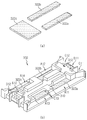
도 8 내지 도 10은 본 발명에 따른 다양한 ICB 조립체를 도시한다. 각 도에서 (a)는 ICB 프레임에 결합되는 버스바를 나타내고, (b)는 ICB 프레임의 (a)의 버스바가 조립된 상태를 나타낸다. 8-10 illustrate various ICB assemblies according to the present invention. In each figure, (a) shows a bus bar coupled to the ICB frame, and (b) shows a state in which the bus bar of (a) of the ICB frame is assembled.
도 8 내지 도 10을 참조하면, 본 발명의 ICB 조립체(301, 302, 303)는 모두 도 7의 ICB 프레임(310)을 포함한다. ICB 조립체(301, 302, 303)는 인쇄 회로 기판이나 전압 센싱을 위한 와이어 부품을 더 포함할 수 있다. 인쇄 회로 기판이나 전압 센싱을 위한 와이어 부품이 이러한 ICB 조립체(301, 302, 303)에 더 연결될 수도 있다. ICB 조립체(301, 302, 303)는 ICB 프레임(310)에 여러 가지 모양의 버스바를 달리 조합하여 포함한다. 버스바는 ICB 프레임(310)에 조립되어 단위 셀(200)의 셀 리드(112)와 전기적 연결된다. 8 to 10, the
먼저 도 8의 ICB 조립체(301)는 도 6의 전기적 연결 관계에서 상단인 제4층에 사용하기 위한 것으로, ICB 프레임(310)에 버스바(321a, 321b, 321c)가 조립된 것이다. First, the
버스바(321a)는 Hv 터미널 버스바로서, 제1 Hv 터미널 안착부(B11)에 놓이는 부분과 제2 셀 리드 안착부(A12)에 놓이는 부분을 포함하고 있다. 버스바(321a)에서 제2 셀 리드 안착부(A12)에 놓이는 부분을 ICB 프레임(310)의 제2 버스바 삽입홀(C12)에 끼워 밀어 넣으면, 도 8에 도시한 대로 버스바(321a)가 제1 Hv 터미널 안착부(B11)와 제2 셀 리드 안착부(A12)에 조립된다. 후속 공정에서 이 버스바(321a)에는 제4층 우측 단위 셀(200)의 음극 셀 리드(112)가 연결된다. 따라서, 버스바(321a)는 배터리 모듈(300) 상단의 Hv 음극(Hv-)을 형성한다.The
버스바(321b)는 제1 셀 리드 안착부(A11)에 놓이는 부분을 포함하고 있는 연결용 버스바이다. 버스바(321b)를 ICB 프레임(310)의 제1 버스바 삽입홀(C11)에 끼워 밀어 넣으면 도 8에 도시한 대로 제1 셀 리드 안착부(A11)에 조립된다. The
버스바(321c)는 관통 버스바로서, ICB 프레임(310)의 관통 버스바 삽입홀(C13)을 통해 삽입되어 제3 및 제4 셀 리드 안착부(A13, A14) 위에 동시에 놓이도록 조립된다. 후속 공정에서 버스바(321c)는 제3 셀 리드 안착부(A13) 위에 놓이는 단위 셀의 셀 리드와, 맞은편 제4 셀 리드 안착부(A14) 위에 놓이는 다른 단위 셀의 셀 리드에 동시 연결되므로, 마주보는 두 단위 셀 사이를 직렬연결할 수 있는 것이다. 따라서, 서로 마주보는 단위 셀을 평면상에서 직렬로 연결하는, 도 6의 "S11"을 실현하기 위한 구성이다. 이처럼 ICB 조립체(301)는 버스바(321c)를 통해 도 6의 전기적 연결 관계에서 배터리 모듈(300) 상단, 즉 제4층에 있는 두 단위 셀(200) 사이를 직렬연결(S11)하고, 버스바(321a)를 통해서는 배터리 모듈(300) 상단의 Hv 음극(Hv-)을 형성하게 되는 부품이다. The
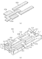
도 9의 ICB 조립체(302)는 ICB 프레임(310)에 버스바(322a, 322b, 322c)가 조립된 것이고, 도 7의 ICB 프레임(310)을 평면상으로 180도 회전하여 도시한 것이며, 도 6의 전기적 연결 관계에서 가운데 층들인 제3층 및 제2층에 사용하기 위한 부품이다. The
버스바(322a)는 연결용 버스바로서, ICB 프레임(310)의 제1 버스바 삽입홀(C11)을 통해 삽입되어 제1 셀 리드 안착부(A11)에 조립이 된다. 버스바(322b)도 연결용 버스바로서, ICB 프레임(310)의 제2 버스바 삽입홀(C12)을 통해 삽입되어 제2 셀 리드 안착부(A12)에 조립이 된다. The
도 9의 버스바(322c)는 도 8의 버스바(321c)와 동일한 것이다. 따라서, 버스바(322c)는 관통 버스바이고, ICB 프레임(310)의 관통 버스바 삽입홀(C13)을 통해 삽입되어 제3 및 제4 셀 리드 안착부(A13, A14) 위에 놓인다. 이로써, 서로 마주보는 단위 셀을 평면상에서 직렬로 연결하는, 도 6의 "S11"을 실현한다. The
이러한 ICB 조립체(302)는 두 개가 필요하며, 그 중 하나는 버스바(322c)를 통해 도 6의 전기적 연결 관계에서 제3층에 있는 두 단위 셀 사이를 직렬연결(S11)하고, 다른 하나는 버스바(322c)를 통해 도 6의 전기적 연결 관계에서 제2층에 있는 두 단위 셀 사이를 직렬연결(S11)하는 데에 이용될 수 있다. Two of these
도 10의 ICB 조립체(303)는 ICB 프레임(310)에 버스바(323a, 323b, 323c)가 조립된 것이고, 도 7의 ICB 프레임(310)을 평면상으로 180도 회전하여 도시한 것이며, 도 6의 전기적 연결 관계에서 하단인 제1층에 사용하기 위한 부품이다. The
버스바(323a)는 Hv 연장 버스바로서, 배터리 모듈(300)의 상단에 형성되는 Hv 양극(Hv+)에 연결하기 위한 것이다. 배터리 모듈(300)의 하단에서 상단으로 직렬연결하기 위한 구성으로서, 후속 공정에서 제1층 우측 단위 셀(200)의 양극 셀 리드(112)는 이 버스바(323a)에 연결이 됨으로써, 도 6의 "S13” 을 구현할 수 있게 된다. 이러한 버스바(323a)는 ICB 프레임(310)에서 제2 Hv 터미널 안착부(B12)에 놓이는 부분과 제1 셀 리드 안착부(A11)에 놓이는 부분을 포함하고 있으며, 이에 따라 제2 Hv 터미널 안착부(B12)와 제1 셀 리드 안착부(A11)에 놓여 조립이 된다. The
버스바(323b)는 연결용 버스바로서 ICB 프레임(310)의 제2 버스바 삽입홀(C12)을 통해 제2 셀 리드 안착부(A12)에 조립이 된다. 버스바(321a, 322a, 322b, 323b)는 모두 연결용 버스바로서 서로 동일한 모양을 가질 수 있다. The
도 10의 버스바(323c)는 앞의 도 8 및 도 9에서 설명한 버스바(321c, 322c)와 동일한 것이다. 버스바(323c)는 ICB 프레임(310)의 관통 버스바 삽입홀(C13)을 통해 삽입되어 제3 및 제4 셀 리드 안착부(A13, A14) 위에 놓이도록 조립된다. 버스바(323c)는 버스바(321c, 322c)와 마찬가지로 제3 셀 리드 안착부(A13) 위에 놓이는 단위 셀의 셀 리드와, 맞은편 제4 셀 리드 안착부(A14) 위에 놓이는 다른 단위 셀의 셀 리드에 동시 연결되므로 마주보는 배터리 셀 사이를 직렬연결할 수 있는 것이다. 따라서, 서로 마주보는 단위 셀을 평면상에서 직렬로 연결하는, 도 6의 "S11"을 실현하는 구성이다. 이러한 ICB 조립체(303)는 버스바(323c)를 통해 도 6의 전기적 연결 관계에서 가장 아래층인 제1층, 즉 배터리 모듈(300) 하단에 있는 두 단위 셀(200) 사이를 직렬연결(S11)하고, 버스바(323a)를 통해 제1층 우측 단위 셀(200)의 양극 셀 리드(112)를 배터리 모듈(300) 상단의 Hv 양극(Hv+)에 직렬연결(S13)할 수 있게 한다. The
이처럼, 버스바(321a, 321b, 321c, 322a, 322b, 322c, 323a, 323b, 323c)는 버스바 프레임(310)에 형성된 단차와 버스바 삽입홀(C11 ~ C13)을 통해 ICB 프레임(310)에 조립될 수 있는 여러 가지 모양의 버스바로 이루어진 군에서 단위 셀(200)간의 전기적 연결 관계를 고려하여 선택한 버스바의 조합이다. As described above, the
앞에서 설명한 바와 같이 ICB 프레임(310)에 다양한 종류의 버스바를 임의의 위치에 조립할 수 있는 여러 개의 단차와 버스바 삽입홀(C11 ~ C13)을 형성해 두므로, 단차와 버스바 삽입홀(C11 ~ C13)의 임의의 조합을 택하여 원하는 위치에 원하는 모양의 버스바를 조립할 수 있게 된다. 버스바는 ICB 프레임(310)에 형성한 단차와 버스바 삽입홀(C11 ~ C13)을 통해 ICB 프레임(310)에 조립될 수 있는 여러 가지 모양의 버스바로 이루어진 군으로 구비해 둘 수 있고, 그 중에서 원하는 전기적 연결 관계를 고려하여 선택한 버스바, 특히 본 실시예에서는 버스바(321a, 321b, 321c, 322a, 322b, 322c, 323a, 323b, 323c)를 다양하게 조합하여 ICB 프레임(310)에 조립할 수 있는 것이다. As described above, since the
동일한 ICB 프레임(310)에 대하여, 버스바(321a, 321b, 321c)를 조합해서는 ICB 조립체(301)를 만들 수 있고, 버스바(322a, 322b, 322c)를 조합해서는 ICB 조립체(302)를 만들 수 있으며, 버스바(323a, 323b, 323c)를 조합해서는 ICB 조립체(303)를 만들 수 있는 예를 설명하였다. 이처럼, 하나의 ICB 프레임 모양을 정해두면 버스바만 바꿔 끼면서 이 ICB 프레임을 여러 가지 전기적 연결에 사용할 수 있게 된다. 따라서, 본 발명의 ICB 조립체는 범용, 다목적, 다용도이다. For the
이러한 본 발명의 ICB 조립체에 따르면, 동일한 ICB 프레임에 여러 가지 모양의 버스바를 차등 적용하여 조립할 수 있다. 보다 자유로운 구성의 전기적 연결이 가능해지는 효과가 있다. According to the ICB assembly of the present invention, various types of bus bars can be differentially applied to the same ICB frame and assembled. It has the effect of enabling a more flexible electrical connection.
한편, 도 8 내지 도 10에 도시한 ICB 조립체(301, 302, 303)의 모양은 예시에 불과하고 본 발명의 ICB 조립체는 이들과는 다른 모양을 가질 수 있음은 물론이다. 본 실시예에서는 3P8S의 배터리 모듈을 예로 들고 있다. 단위 셀(200)로서 이미 3P 구조를 갖는 것을 이용하여 병렬연결을 구현한 경우이므로, ICB 프레임(310)의 버스바(321a, 321b, 321c, 322a, 322b, 322c, 323a, 323b, 323c)는 단위 셀(200)의 직렬연결을 위한 것으로 예를 들었다. 물론, 배터리 모듈 내의 직렬/연결 구조에 따라 ICB 프레임의 모양, 여기에 조립되는 버스바 모양과 위치는 얼마든지 달라질 수 있음을 이해하여야 한다. Meanwhile, the shapes of the
ICB 조립체(301, 302, 303)는 서로 나란히 ICB 프레임(310)의 길이(L) 방향으로 연결될 수 있다. 즉, ICB 조립체(301, 302, 303)는 ICB 프레임(310)의 길이(L) 방향으로 다른 ICB 프레임(310)에 연결될 수 있다. 예를 들어 도 11에 도시한 바와 같이, ICB 조립체(301) 옆에 다른 ICB 조립체(302)가 나란히 배열된 후에 이들 사이가 연결될 수 있다. 도 11에는 ICB 조립체(301)의 ICB 프레임(310) 제4 측변(311d) 옆에 ICB 조립체(302)의 ICB 프레임(310) 제4 측변(311d)이 오도록 배열된 상태가 도시되어 있다. The
이 때, 도 12에 도시한 바와 같은 조인트 부재(315)를 이용할 수 있다. 조인트 부재(315)를 중심으로 두 ICB 프레임(310)이 회동할 수 있도록, 힌지 구조로 연결함이 바람직하다. 이를 위해, ICB 프레임(310)의 측면에 봉 형상 돌출부(312)를 형성하고, 길이(L) 방향을 따라 나열된 두 ICB 프레임(310)의 측면 사이에 조인트 부재(315)로 연결할 수 있다. 본 실시예에서 조인트 부재(315)는 대략 H자 모양이면서 단부 4곳에 홈(316)을 구비하고 있다. 이 홈(316)이 ICB 프레임(310)의 측면, 본 실시예에서는 제3 및 제4 측변(311c, 311d)에 형성된 돌출부(312)에 끼워질 수 있다. At this time, the
도 13은 이 조인트 부재(315)를 이용해 ICB 조립체(301)의 ICB 프레임(310) 측면을 다른 ICB 조립체(302)의 ICB 프레임(310) 측면에 길이 방향을 따라 연결한 상태를 도시한다. FIG. 13 shows a state in which the side of the
ICB 프레임(310)의 제3 및 제4 측변(311c, 311d)에 봉 형태의 돌출부(312)를 만들고, 조인트 부재(315)의 홈(316)을 이 봉에 끼워지는 C자 형으로 만들면, 홈(316)의 열린 부분을 ICB 프레임(310)의 돌출부(312)에 끼워 두 ICB 프레임(310) 사이를 연결할 수 있다. 그리고, 홈(316) 안에서 돌출부(312)가 돌아가거나 돌출부(312)를 돌아 홈(316)이 움직임으로써 두 ICB 프레임(310)은 조인트 부재(315)를 기점으로 회동할 수 있다. Making the rod-shaped
본 실시예에서 조인트 부재(315)의 단부 2곳은 한 쪽의 ICB 프레임(310)의 두 돌출부(312)에 각각 끼워지고, 맞은편 단부 2곳은 다른 한 쪽의 ICB 프레임(310)의 두 돌출부(312)에 각각 끼워지도록 구성하여, 대략 H자 모양이 ICB 프레임(310)의 길이 방향을 따라 가로로 평면에 놓이도록 하는 예를 들었다. 힌지 연결 구조를 실현할 수 있는 것이라면 조인트 부재(315)와 돌출부(312) 구조가 도시된 예에 한정되지 않고 다양하게 구성될 수 있다. In this embodiment, the two ends of the
이와 같이, 본 발명에 따른 배터리 모듈 제조 방법은 상기와 같이 준비된 여러 가지 ICB 조립체(301, 302, 303)의 ICB 프레임(310)을 힌지 구조로 측면 연결하여 ICB 프레임(310)의 길이(L) 방향으로 나열하는 단계를 포함한다. In this way, the battery module manufacturing method according to the present invention is the length (L) of the
도 14는 도 12에 설명한 바와 같은 조인트 부재(315)를 이용해 ICB 조립체(301, 302, 303)의 ICB 프레임(310) 4개 사이를 길이(L) 방향으로 측면 연결해 나열한 상태를 도시한다. FIG. 14 shows a state in which the four
가장 좌측에 있는 ICB 조립체(301)의 ICB 프레임(310)에 대해 그 옆의 ICB 조립체(302)의 ICB 프레임(310)은 평면상으로 180도 회전하여 연결된다. 그 ICB 조립체(302)의 ICB 프레임(310)에 대해 우측의 다른 ICB 조립체(302)의 ICB 프레임(310)은 평면상으로 180도 회전하여, ICB 조립체(301)의 ICB 프레임(310)과 같은 방향으로 연결된다. 여기에 대해 가장 우측에 있는 ICB 조립체(303)의 ICB 프레임(310)은 평면상으로 180도 회전하여 연결된다. The
본 실시예에서는 3P8S의 배터리 모듈을 예로 들고 있다. ICB 프레임(310) 하나에 2개의 단위 셀(200)이 연결될 수 있으므로, 총 8개의 단위 셀을 연결하려면 ICB 프레임(310)이 4개 필요한 것임을 이해하여야 한다. 그리고, 배터리 모듈 안의 단위 셀 개수에 따라 필요한 ICB 프레임의 개수가 달라질 수 있음을 알 수 있을 것이다. In this embodiment, the battery module of 3P8S is taken as an example. Since two
본 발명에 따른 배터리 모듈 제조 방법은 이상과 같이 측면 연결된 ICB 조립체를 이용해 단위 셀을 평면 나열하는 단계를 포함한다. 그리고, 나열된 단위 셀을 상면에서 일괄 용접하는 단계를 포함한다. The battery module manufacturing method according to the present invention includes the steps of flatly arranging the unit cells using the ICB assembly connected to the side as described above. And, the step of collectively welding the unit cells listed in the upper surface.
도 15는 본 발명의 일 실시예에 따른 배터리 모듈 제조 방법에서 단위 셀 안착 단계 및 용접 단계를 설명하기 위한 도면이다. 15 is a view for explaining the unit cell seating step and the welding step in the battery module manufacturing method according to an embodiment of the present invention.
도 14에서 본 바와 같이 필요한 개수만큼의 ICB 조립체(301, 302, 303)를 나열하여 조인트 부재(315)로 서로의 ICB 프레임(310)을 측면 연결한 후에, 도 15를 참조하여, 도 2에서 설명한 것과 같은 단위 셀(200)의 셀 리드(112)를 ICB 프레임(310)의 셀 리드 안착부(A11 ~ A14)에 안착시킨다. 하나의 ICB 프레임(310)을 기준으로 좌우측 양측으로 단위 셀(200)을 놓는다. ICB 조립체(301, 302, 303)에서 ICB 프레임(310)의 각 셀 리드 안착부(A11 ~ A14)에는 버스바(321a, 321b, 321c, 322a, 322b, 322c, 323a, 323b, 323c)가 조립되어 있다. 단위 셀(200)의 셀 리드(112)는 버스바(321a, 321b, 321c, 322a, 322b, 322c, 323a, 323b, 323c) 위에 놓이게 된다. As shown in FIG. 14, after as
이 때 ICB 프레임(310)을 기준으로 서로 마주보는 셀 리드(112)는 도 6과 같은 전기적 연결 관계를 구현하기 위한 것이므로 반대 극성이다. 만약 도 6과 같은 전기적 연결 관계와 다른 것을 구현한다면, 마주보는 셀 리드(112)는 서로 같은 극성일 수도 있고 그에 따라 ICB 프레임(310)에 결합되는 버스바 종류와 모양들은 달라질 수 있을 것이고 그에 따라 ICB 프레임(310)의 모양도 달라질 수 있음을 알 수 있을 것이다. At this time, the cell leads 112 facing each other based on the
이해를 돕기 위하여 도 6의 전기적 연결 관계에서 제1층 내지 제4층에 해당하는 부분을 도 15에도 나타내었다. 전부 8개의 단위 셀(200)이 모두 평면 나열되어 각 단위 셀(200)의 셀 리드(112)가 버스바(321a, 321b, 321c, 322a, 322b, 322c, 323a, 323b, 323c) 위로 안착이 된 후, 상면에서 일괄 용접을 실시하여 각 단위 셀(200)의 셀 리드(112)와 그 아래에 놓인 버스바(321a, 321b, 321c, 322a, 322b, 322c, 323a, 323b, 323c) 사이를 연결한다. 이로써, ICB 조립체(301, 302, 303)와 단위 셀(200)이 연결된다. 용접은 레이저 용접 또는 초음파 용접을 이용할 수 있다. 전압 센싱을 위한 와이어 부품을 더 포함하는 경우, 이 과정에서 그 부품도 동시에 용접 가능하다. In order to facilitate understanding, portions corresponding to the first to fourth layers in the electrical connection relationship of FIG. 6 are also illustrated in FIG. 15. All eight
도 15의 용접까지 실시하면 관통 버스바(321c, 322c, 323c)에 서로 연결되며 서로 마주보는 단위 셀(200)끼리는 전기적 연결이 되어 있지만, ICB 프레임(310)의 나열 방향을 따라 옆으로 나란히 놓인 다른 단위 셀(200)끼리는 전기적 연결이 아직 안되어 있다. 즉, 도 6에서 서로 마주보는 단위 셀(200)의 셀 리드(112)끼리 평면상에서 직렬연결(S11)은 되어 있지만, 위 아래로 놓이는 단위 셀(200)의 셀 리드(112)끼리 상하 직렬연결(S12)되는 구성이 아직 실현되어 있지 않다. When the welding of FIG. 15 is carried out, the through
이제, 나열된 ICB 프레임(310)을 힌지 부분인 조인트 부재(315)를 기점으로 지그재그로 접어올리면 단위 셀(200)이 병풍식 접철 구조로 적층된다. 예를 들어 도 16에 도시한 방법대로 접을 수 있다. 도 16은 본 발명의 배터리 모듈 제조 방법에서 병풍식 접철 방식으로 단위 셀을 적층하는 단계를 설명하기 위한 도면이다. Now, when the
도 16을 참조하여 먼저 (a)와 같이 가운데 부분에서부터 안쪽으로 반으로 접는다. 즉 두 ICB 조립체(302) 사이의 조인트 부재(315)를 기점으로 도 15의 구조를 반으로 접는다. 이어서 도 16의 (b), (c) 순으로 진행해 완전히 포갠 후, (d)에서와 같이 가장 바깥쪽에 있는 단위 셀(200)을 바깥쪽으로 접어 내린다. 즉, ICB 조립체(301)와 ICB 조립체(302) 사이의 조인트 부재(315), 그리고 ICB 조립체(302)와 ICB 조립체(303) 사이의 조인트 부재(315)를 기점으로 접는다. 그러면 (e)와 같이 역 W자로 접혀지면서 적층이 되고, 최종적으로는 도 17과 같이 제1층 내지 제4층 총 4개층이 적층된 구조로 접을 수 있다. 도 17에는 도 6 전기적 연결 관계에서의 제4층이 상단에 놓이도록 도시하였다. With reference to FIG. 16, firstly, it is folded in half from the center portion as shown in (a). That is, the structure of FIG. 15 is folded in half, starting from the
이와 같이 본 발명에 따른 배터리 모듈 제조 방법은 ICB 조립체의 버스바에 셀 리드가 용접된 단위 셀을 접어 적층하는 단계를 포함한다. As described above, the method for manufacturing a battery module according to the present invention includes folding and stacking unit cells welded with cell leads on a bus bar of an ICB assembly.
도 18은 본 발명의 일 실시예에 따른 배터리 모듈 제조 방법에서 단위 셀의 직렬연결, 구체적으로 상하 직렬연결(S12)과 하단에서 상단으로 직렬연결(S13)을 완성하기 위해 추가로 필요한 별도의 추가 버스바를 결합하는 단계를 설명하기 위한 도면이다. 도 18에서 (a)는 추가 버스바를 나타내고, (b)는 (a)의 추가 버스바가 결합된 상태를 나타낸다.18 is a series of unit cells in the battery module manufacturing method according to an embodiment of the present invention, specifically up and down the serial connection (S12) and the bottom to the top to complete the series connection (S13) additionally required additional additional It is a diagram for explaining the steps of coupling the busbar. In FIG. 18, (a) shows an additional bus bar, and (b) shows a state in which the additional bus bar of (a) is coupled.
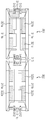
도 17과 같이 적층한 후, ICB 프레임(310)에서 측면(도시한 예에서는 좌측이고 ICB 프레임(310)에서는 제3 측변(311c) 쪽이다)으로 노출되어 있는 위 아래층 버스바(321b, 322b) 사이에 추가 버스바(330a)를 결합한다. 결합 방법은 덧대어 용접하는 방법이 될 수 있다. 이를 통해, 버스바(321b, 322b) 사이가 연결되면서 제4층 좌측 단위 셀(200)과 제3층 좌측 단위 셀(200) 사이가 상하 직렬연결(S12)된다. After stacking as shown in FIG. 17, the upper and
그리고 그 아래에 마찬가지로 측면으로 노출되어 있는 위 아래층 버스바(322a, 323b) 사이에 추가 버스바(330b)를 결합한다. 버스바(322a, 323b) 사이가 연결되면서 제2층 좌측 단위 셀(200)과 제1층 좌측 단위 셀(200) 사이가 상하 직렬연결(S12)된다. In addition, an
또한, 그 옆에 마찬가지로 측면으로 노출되어 있는 위 아래층 버스바(322a, 322b) 사이에 추가 버스바(330C)를 결합한다. 버스바(322a, 322b) 사이가 연결되면서 제3층 우측 단위 셀(200)과 제2층 우측 단위 셀(200) 사이가 상하 직렬연결(S12)된다. Also, an additional bus bar 330C is coupled between the upper and
이와 같이, 측면에서 추가 버스바(330a, 330b, 330c)를 덧대어 용접하는 등의 방법으로 결합시키면 상하 직렬연결(S12)이 모두 구현되며, 도 16의 구조에서 ICB 프레임(310)의 나열 방향을 따라 옆으로 나란히 놓인 다른 단위 셀(200)끼리, 그리고 도 17의 구조에서 적층되어 위 아래에 놓인 다른 단위 셀(200)끼리의 연결이 이루어지게 된다.As described above, when the
ICB 프레임(310)의 타측면(도시한 예에서는 우측이고 ICB 프레임(310)에서는 제4 측변(311d) 쪽이다)으로는 하단에 버스바(323a, 도면에서는 위치상 보이지는 않음)가 노출된다. 여기에는 추가 버스바(330d)를 결합한다. 그러면, 도 6의 "S13"가 구현이 된다. The other side of the ICB frame 310 (the right side in the illustrated example and the
추가 버스바(330a, 330b, 330c, 330d)의 모양과 개수는 직렬/병렬연결 구조에 따라 달라질 것이다. 본 실시예에서 도 18에 도시한 3개의 단순 직사각형 모양의 추가 버스바(330a, 330b, 330c)는 적층 상태에서 서로 위 아래 이웃한 층의 단위 셀(200)간을 연결하는 것이다. 추가 버스바(330a)는 제4층과 제3층의 단위 셀(200)간을 연결한다. 추가 버스바(330b)는 제2층과 제1층의 단위 셀(200)간을 연결한다. 추가 버스바(330c)는 제3층과 제2층의 단위 셀(200)간을 연결한다. The shape and number of
1개의 ㄱ자형 추가 버스바(330d)는 제1층에서부터 배터리 모듈(300)의 측면을 따라 제4층에 걸쳐지도록 형성이 되며, 추가 버스바(330d)의 일측은 ICB 조립체(303)의 버스바(323a)에 연결이 되어 제1층 우측 단위 셀(200)의 양극 셀 리드(112)와 연결이 되고, 추가 버스바(330d)의 타측은 제4층 ICB 조립체(301)의 Hv 터미널 안착부(B12)에 안착되어 Hv 양극(Hv-)을 형성하게 된다. One a-shaped
이상 설명한 바와 같이, 본 발명에 따른 배터리 모듈 제조 방법은 지면에서부터 높이 방향으로 적층된 단위 셀끼리의 상하 직렬연결(S12)을 위해 측면에서 추가 버스바 결합하는 단계를 포함한다. 이와 같이, 추가 버스바 결합에 의해 도 18과 같은 본 발명의 일 실시예에 따른 배터리 모듈(300)이 완성된다. 이 배터리 모듈(300)은 도 6에 설명한 바와 같은 전기적 연결 관계를 가진 것이며, 셀 리드들의 극성을 따져 복잡하게 서로간을 연결할 필요없이, ICB 조립체(301, 302, 303)를 준비하고 여기에 단위 셀(200)을 배열한 후 일괄 용접하고 접어 적층하는 등 앞서 설명한 바와 같은 제조 방법을 통해 간단히 제조되는 것이다. 이와 같이 본 발명의 실시예에 따르면 8개의 3P 뱅크 단위 셀(200) 8개가 모두 직렬연결되어, 3P8S 전기적 연결을 실현한 수평 적층 구조의 배터리 모듈을 매우 간단한 방법으로 제조할 수 있게 된다. As described above, the method for manufacturing a battery module according to the present invention includes the step of coupling an additional busbar from the side for vertical connection (S12) of the unit cells stacked in the height direction from the ground. As such, the
이처럼 본 발명은 배터리 셀의 수평 적층 + 단방향 배터리 셀이 마주보는 구조의 배터리 모듈 제작시, 두 배터리 셀을 마주보도록 적층 후 셀 리드 간 용접, 그 위에 두 배터리 셀을 마주보도록 적층 후 셀 리드간 용접, 다시 그 위에 두 배터리 셀을 마주보도록 적층 후 셀 리드간 용접하는 종래의 방법처럼, 적층과 용접을 순차적으로 반복하지 않아도 되는 장점이 있다. 배터리 셀을 평면에 나열하여 상면에서 일괄 용접하는 단계, 접어서 적층하는 단계, 적층된 배터리 셀끼리 상하로 연결되도록 측면에서 추가 버스바 결합하는 단계들을 포함하여 간단히 배터리 모듈을 제조할 수 있다.As described above, in the case of manufacturing a battery module having a horizontal stacking of battery cells + a unidirectional battery cell facing each other, stacking to face the two battery cells and welding between the cell leads, stacking to face the two battery cells and welding between the cell leads , There is an advantage that it is not necessary to repeat the stacking and welding sequentially, as in the conventional method of stacking two battery cells on top of each other and then welding between the cell leads. Battery modules can be manufactured simply by arranging the battery cells in a flat surface and welding them on the upper surface, folding and stacking, and bonding additional busbars on the side to connect the stacked battery cells up and down.
이상 상세히 설명한 바와 같이, 본 발명은 이러한 배터리 모듈 제조 방법을 수행하기 위한, 신규 구조의 ICB 조립체도 제안한다. 이러한 ICB 조립체는 동일한 모양의 ICB 프레임에 여러가지 모양의 버스바를 다양한 조합으로 끼워 사용할 수 있으며, 힌지 연결 구조를 통해 다른 ICB 조립체와 연결할 수 있는 것이어서 연결 부위를 기점으로 ICB 조립체를 접으면 ICB 조립체에 연결되어 있는 배터리 셀이 적층될 수 있게 하는 신규의 부품인 것이다. 즉, 본 발명의 ICB 조립체는 힌지 연결 구조로 접어서 적층할 수 있으며 다양한 전기적 연결 관계를 구현할 수 있도록 다양한 버스바를 바꿔 낄 수 있는 부품이다. As described in detail above, the present invention also proposes a new structure of the ICB assembly for performing such a battery module manufacturing method. These ICB assemblies can be used in various combinations of busbars of various shapes in the same shape of the ICB frame, and can be connected to other ICB assemblies through a hinged connection structure. It is a new component that enables stacked battery cells to be stacked. That is, the ICB assembly of the present invention is a component that can be folded and stacked in a hinged connection structure and can be replaced with various bus bars to implement various electrical connection relationships.
이상 설명한 바와 같이, 본 발명의 실시예에서 설명한 옵션 1 구조는 도 18과 같은 배터리 모듈(300)로 구현이 되며, type 1 ICB 프레임에 Hv 터미널 버스바, 연결용 버스바, 관통 버스바, Hv 연장 버스바 등과 같은 여러 가지 다른 모양의 버스바를 끼운 3가지 종류의 ICB 조립체를 총 4개 마련하고, 그러한 ICB 조립체를 이용해 단위 셀을 평면에 나열하여 상면에서 버스바와 단위 셀의 셀 리드를 상면에서 일괄 용접, 접어서 적층, 그리고 적층된 단위 셀끼리의 상하 직렬연결을 위해 측면에서 추가 버스바 결합하는 방법으로 제조할 수 있다. As described above, the option 1 structure described in the embodiment of the present invention is implemented by the
이러한 배터리 모듈(300)은 ICB 조립체(303)를 통해 수평 방향으로 서로 연결된 두 단위 셀(200), ICB 조립체(302)를 통해 수평 방향으로 서로 연결된 두 단위 셀(200), 그리고 ICB 조립체(301)를 통해 수평 방향으로 서로 연결된 단위 셀(200)이 지면에서부터 높이 방향으로 적층되어 있고, 배터리 모듈(300) 상단에 Hv 터미널[Hv 양극(Hv+)과 Hv 음극(Hv-)]이 형성되어 있다. ICB 조립체(301, 302, 303) 사이는 조인트 부재(315)로 연결되어 있으며, ICB 조립체(301, 302, 303) 측면에서는 단위 셀(200)의 상하 직렬연결을 위한 추가 버스바(330a, 330b, 330c)가 결합되어 있고, 하단에서 상단으로 직렬연결하기 위한 추가 버스바(330d)도 ICB 조립체(301, 302, 303)의 다른 측면에 결합되어 있다. 평면상에서 마주보는 두 단위 셀(200) 사이는 ICB 조립체(301, 302, 303)에 조립된 관통 버스바인 각 버스바(321c, 322c, 323c)를 통해 평면상에서 직렬연결되어 있으며, 지면에서부터 높이 방향으로 적층되어 있는 단위 셀(200) 사이는 추가 버스바(330a, 330b, 330c)를 통해 상하 직렬연결되어 있다. ICB 조립체(301, 302, 303)의 ICB 프레임(310)은 서로 동일한 모양이고 버스바(321a, 321b, 321c, 322a, 322b, 322c, 323a, 323b, 323c)만 바꿔 끼워 차등 적용한 여러 가지 종류의 ICB 조립체이다. The
이처럼, 본 발명의 ICB 조립체를 이용하면 다수의 배터리 셀을 평면에 나열하여 일괄 용접하고 접어서 적층해 배터리 모듈을 제조할 수 있다. 특히 ICB 조립체는 다수의 배터리 셀을 전기적 연결하는 수많은 경우의 수 중 가장 간단한 연결 관계를 구현할 수 있게 한다. 이를 이용한 본 발명의 배터리 모듈 제조 방법에 따르면, 단방향 배터리 셀을 수평 적층하고 단방향 배터리 셀이 서로 마주보는 구조의 배터리 모듈 제조 단계가 매우 간단해진다. As described above, by using the ICB assembly of the present invention, a plurality of battery cells can be arranged on a flat surface, batch-welded, folded and stacked to manufacture a battery module. In particular, the ICB assembly makes it possible to implement the simplest connection relationship among a number of cases in which multiple battery cells are electrically connected. According to the battery module manufacturing method of the present invention using this, the steps of manufacturing a battery module having a structure in which unidirectional battery cells are horizontally stacked and unidirectional battery cells face each other are greatly simplified.
본 발명의 배터리 모듈은 본 발명의 ICB 조립체를 포함함으로써 조립이 매우 용이하다. 그리고, 배터리 셀 - ICB 조립체 - 배터리 셀의 단위를 추가로 더 포함시키는 간단한 과정을 통해 직렬연결되는 배터리 셀 개수를 증가시킬 수 있어 배터리 모듈의 확장이 얼마든지 가능하다는 장점이 있다. 즉, 본 발명의 배터리 모듈은 ICB 조립체를 가운데에 두고 서로 마주보면서 연결된 배터리 셀 - ICB 조립체 - 배터리 셀의 단위를 지면에서 높이 방향으로 여러 층 적층한 것이므로, 배터리 셀 - ICB 조립체 - 배터리 셀의 단위의 개수를 증가시키면 배터리 모듈의 확장이 가능하다. The battery module of the present invention is very easy to assemble by including the ICB assembly of the present invention. In addition, the number of battery cells connected in series can be increased through a simple process of further including a unit of a battery cell-an ICB assembly-a battery cell, and thus an extension of the battery module is possible. That is, the battery module of the present invention is a battery cell connected to each other with the ICB assembly in the center-ICB assembly-since the battery cell unit is stacked in multiple layers in the height direction from the ground, the battery cell-ICB assembly-unit of the battery cell Increasing the number of can expand the battery module.
본 발명에 따르면, 배터리 모듈을 구성하는 다수의 배터리 셀 사이의 무수히 많은 전기적 연결 관계의 경우의 수 중에서 가장 단순하며, 공법이 간단한 연결을 제공할 수 있다. 배터리 셀 적층을 위한 적층 가이드로 힌지 구조가 적용될 수 있으며, ICB 조립체 사이의 전기적 연결은 ICB 프레임 측면에 추가 버스바를 덧대어 용접하는 등 결합하여 달성할 수 있다. According to the present invention, it is the simplest of the number of cases of a myriad of electrical connection relationships between a plurality of battery cells constituting a battery module, and a simple construction method can be provided. The hinge structure can be applied as a stacking guide for stacking battery cells, and the electrical connection between ICB assemblies can be achieved by joining, for example, welding an additional busbar on the side of the ICB frame.
한편 위 실시예에서는 제1층 내지 제4층 각각의 층에 대해 2개의 셀 뱅크 단위 셀(200)당 1개의 ICB 프레임을 적용하여 배터리 모듈(300)을 제조하는 실시예를 설명하였으나, 2개 층마다 ICB 프레임을 제공하여 ICB 프레임 하나에 4개의 단위 셀(200)이 놓이는 실시예도 가능하다. 그러면 단위 셀(200) 2개는 ICB 프레임의 상면에, 나머지 2개는 ICB 프레임의 하면에 놓인다. 이와 같이 4개의 단위 셀(200)을 연결하는 ICB 프레임을 type 2 ICB 프레임이라고 불러 앞의 type 1 ICB 프레임과 구별할 수 있다. 총 8개의 단위 셀(200)을 포함하는 배터리 모듈의 경우, 총 2개의 type2 ICB 프레임이 필요하다. 여기서도 ICB 프레임들은 길이 방향으로 나란히 연결될 수 있으며, 서로 연결되는 ICB 프레임의 모양은 모두 동일하다. 여기에, 각기 다른 모양의 버스바를 적용함으로써 다양한 전기적 연결 관계를 구현할 수 있다. 예를 들어, 어떤 ICB 프레임에는 ㄷ 버스바를 적용하고 다른 ICB 프레임에는 S 버스바를 적용하는 등, 동일한 모양의 ICB 프레임에 다른 모양의 다양한 버스바를 적용해 다양한 구성의 ICB 조립체를 만들고 이를 이용해 배터리 모듈을 제조할 수 있다. Meanwhile, in the above embodiment, an embodiment in which the
ICB 프레임에 연결되는 단위 셀의 개수, 그리고 ICB 프레임의 상면과 하면 모두에 단위 셀을 연결함에 따라 이에 적합한 버스바, 즉 ICB 프레임의 상면과 하면에 조립될 수 있는 버스바를 포함해야 한다는 점, 그리고 구체적인 전기적 연결 관계 등을 제외하고는, 앞의 실시예에서 설명한 ICB 조립체, 배터리 모듈 제조 방법 및 배터리 모듈에 관한 모든 사항을 그대로 적용할 수 있다.The number of unit cells connected to the ICB frame, and the connection of the unit cells to both the upper and lower surfaces of the ICB frame should include a bus bar suitable for this, that is, a bus bar that can be assembled to the upper and lower surfaces of the ICB frame, and Except for a specific electrical connection relationship, all the items related to the ICB assembly, the battery module manufacturing method, and the battery module described in the previous embodiment can be applied as it is.
이상과 같이, 본 발명은 비록 한정된 실시예와 도면에 의해 설명되었으나, 본 발명은 이것에 의해 한정되지 않으며 본 발명이 속하는 기술분야에서 통상의 지식을 가진 자에 의해 본 발명의 기술사상과 아래에 기재될 청구범위의 균등범위 내에서 다양한 수정 및 변형이 가능함은 물론이다.As described above, although the present invention has been described by a limited number of embodiments and drawings, the present invention is not limited by this, and the technical idea of the present invention and the following will be described by those skilled in the art to which the present invention pertains. Of course, various modifications and variations are possible within the scope of the claims to be described.
112 : 셀 리드
200 : 단위 셀
300 : 배터리 모듈
301, 302, 303 : ICB 조립체
310 : ICB 프레임
311a : 제1 측변
311b : 제2 측변
311c : 제3 측변
311d : 제4 측변
312 : 돌출부
315 : 조인트 부재
316 : 홈
A11 : 제1 셀 리드 안착부
A12 : 제2 셀 리드 안착부
A13 : 제3 셀 리드 안착부
A14 : 제4 셀 리드 안착부
B11 : 제1 Hv 터미널 안착부
B12 : 제2 Hv 터미널 안착부
C11 : 제1 버스바 삽입홀
C12 : 제2 버스바 삽입홀
C13 : 관통 버스바 삽입홀
321a : Hv 터미널 버스바
321b, 322a, 322b, 323b : 연결용 버스바
321c, 322c : 관통 버스바
323a : Hv 연장 버스바
330a~330d : 추가 버스바112: cell lead
200: unit cell
300: battery module
301, 302, 303: ICB assembly
310: ICB frame
311a: first side
311b: second side
311c: third side
311d: 4th side
312: protrusion
315: joint member
316: home
A11: First cell lead seat
A12: Second cell lead seat
A13: Third cell lead seat
A14: 4th cell lead seating part
B11: First Hv terminal seat
B12: Second Hv terminal seat
C11: 1st bus bar insertion hole
C12: 2nd bus bar insertion hole
C13: Through bus bar insertion hole
321a: Hv terminal bus bar
321b, 322a, 322b, 323b: Bus bar for connection
321c, 322c: Through bus bar
323a: Hv extension bus bar
330a ~ 330d: Additional bus bar
Claims (22)
상기 ICB 프레임에 조립되어 상기 셀 리드와 전기적 연결되는 버스바를 포함하는 ICB 조립체.An ICB frame for accommodating the cell leads such that unidirectional battery cells having cell leads formed at one end thereof are placed facing each other with the cell leads facing each other; And
An ICB assembly including a bus bar assembled to the ICB frame and electrically connected to the cell lead.
상기 Hv 터미널 안착부는 상기 제1 및 제2 측변에 수직인 너비 방향 제3 및 제4 측변 쪽에 각각 형성이 되어 있어, 제3 측변 쪽의 제1 Hv 터미널 안착부와 제4 측변 쪽의 제2 Hv 터미널 안착부를 포함하는 것을 특징으로 하는 ICB 조립체. The method of claim 5, wherein the cell lead seating portion is formed on both sides along the first and second sides in the longitudinal direction of the ICB frame, the first cell lead seating portion and the third cell along the first side A lead seating portion is formed and includes a second cell lead seating portion facing the first cell lead seating portion along the second side, and a fourth cell lead seating portion facing the third cell lead seating portion,
The Hv terminal seating portion is formed on the third and fourth side sides, respectively, in the width direction perpendicular to the first and second side edges, so that the first Hv terminal seat portion on the third side side and the second Hv side on the fourth side side are formed. ICB assembly comprising a terminal seat.
상기 제1 셀 리드 안착부에 놓이는 연결용 버스바와, 상기 제3 및 제4 셀 리드 안착부 위에 동시에 놓이는 관통 버스바를 포함하는 것을 특징으로 하는 ICB 조립체. The HV terminal bus bar of claim 8, wherein the bus bar includes a portion placed on the first Hv terminal seating portion and a portion placed on the second cell lead seating portion,
ICB assembly characterized in that it comprises a bus bar for connection to be placed on the first cell lead seating portion, and a through-bus bar placed on the third and fourth cell lead seating portions at the same time.
(b) 상기 ICB 조립체의 상기 ICB 프레임을 힌지 구조로 측면 연결하여 상기 ICB 프레임 길이 방향으로 나열하는 단계;
(c) 측면 연결된 ICB 프레임 길이 방향 좌우측에 상기 배터리 셀을 안착시켜 상기 배터리 셀이 서로 마주보도록 평면 상에 나열하되, 상기 버스바 위로 상기 셀 리드를 안착시켜 상기 배터리 셀을 평면 나열하는 단계;
(d) 나열된 배터리 셀에 대해 상면에서 상기 버스바와 셀 리드를 일괄 용접하여 상기 ICB 조립체와 상기 배터리 셀을 연결하는 단계;
(e) 나열된 상기 ICB 프레임을 상기 힌지 부분에서 접어서 상기 배터리 셀을 적층하는 단계; 및
(f) 상기 ICB 프레임에서 측면으로 노출되어 있는 버스바 사이에 추가 버스바를 결합하는 단계를 포함하는 배터리 모듈 제조 방법.(a) an ICB frame for accommodating the cell leads such that the unidirectional battery cells in which the cell leads are formed at one end face each other and the cell leads face each other; And preparing an ICB assembly including a bus bar assembled to the ICB frame and electrically connected to the cell lead, but preparing various ICB assemblies by differentially applying only the bus bar to the same shape of the ICB frame;
(b) side-by-side connecting the ICB frames of the ICB assembly with a hinge structure to arrange the ICB frames in the longitudinal direction;
(c) seating the battery cells on the left and right sides of a side-connected ICB frame lengthwise and arranging them on a plane so that the battery cells face each other, and placing the cell leads on the bus bar to planarly arrange the battery cells;
(d) connecting the ICB assembly and the battery cell by collectively welding the bus bar and the cell lead on the upper surface of the listed battery cells;
(e) folding the ICB frames listed at the hinge portion to stack the battery cells; And
(f) a method of manufacturing a battery module comprising the step of coupling an additional busbar between the busbars exposed sideways in the ICB frame.
각 ICB 조립체는 상기 셀 리드를 수용하는 ICB 프레임; 및 상기 ICB 프레임에 조립되어 상기 셀 리드와 전기적 연결되는 버스바를 포함하며, 적층된 ICB 조립체 사이는 조인트 부재로 연결되어 있고, 적층된 ICB 조립체 측면에서는 상기 배터리 셀의 상하 직렬연결을 위한 추가 버스바가 결합되어 있으며,
상기 각 ICB 조립체의 ICB 프레임은 서로 동일한 모양이고 버스바만 바꿔 끼워 차등 적용한 여러 가지 종류의 ICB 조립체인 것을 특징으로 하는 배터리 모듈.Battery cells connected to each other with ICB assemblies centered so that unidirectional battery cells with cell leads formed on one end are placed facing each other with cell leads facing each other-ICB assembly-unit of battery cells in a height direction from the ground Stacked battery modules,
Each ICB assembly includes an ICB frame accommodating the cell lead; And a bus bar assembled to the ICB frame and electrically connected to the cell lead, connected between the stacked ICB assemblies with a joint member, and on the side of the stacked ICB assembly there is an additional bus bar for vertical connection of the battery cells. Combined,
The ICB frame of each ICB assembly is the same shape and is a battery module, characterized in that various types of ICB assemblies that are differentially applied by swapping only busbars.
Priority Applications (8)
| Application Number | Priority Date | Filing Date | Title |
|---|---|---|---|
| KR1020180107985A KR102404239B1 (en) | 2018-09-10 | 2018-09-10 | ICB assembly, battery module comprising the same and method for fabricating the battery module |
| US17/258,850 US12100863B2 (en) | 2018-09-10 | 2019-09-04 | ICB assembly, battery module comprising the same and method for fabricating the battery module |
| JP2021516517A JP7062137B2 (en) | 2018-09-10 | 2019-09-04 | ICB assembly, battery module including it and its manufacturing method |
| HUE19859352A HUE065678T2 (en) | 2018-09-10 | 2019-09-04 | Icb assembly, battery module comprising the same and method for fabricating the battery module |
| EP19859352.7A EP3793015B1 (en) | 2018-09-10 | 2019-09-04 | Icb assembly, battery module comprising the same and method for fabricating the battery module |
| CN201980036270.9A CN112204803B (en) | 2018-09-10 | 2019-09-04 | ICB assembly, battery module including the same, and method of manufacturing the battery module |
| PCT/KR2019/011423 WO2020055037A1 (en) | 2018-09-10 | 2019-09-04 | Icb assembly, battery module including same, and manufacturing method therefor |
| ES19859352T ES2975801T3 (en) | 2018-09-10 | 2019-09-04 | ICB assembly, battery module comprising the same and method of manufacturing the battery module |
Applications Claiming Priority (1)
| Application Number | Priority Date | Filing Date | Title |
|---|---|---|---|
| KR1020180107985A KR102404239B1 (en) | 2018-09-10 | 2018-09-10 | ICB assembly, battery module comprising the same and method for fabricating the battery module |
Publications (2)
| Publication Number | Publication Date |
|---|---|
| KR20200029307A true KR20200029307A (en) | 2020-03-18 |
| KR102404239B1 KR102404239B1 (en) | 2022-05-30 |
Family
ID=69776706
Family Applications (1)
| Application Number | Title | Priority Date | Filing Date |
|---|---|---|---|
| KR1020180107985A KR102404239B1 (en) | 2018-09-10 | 2018-09-10 | ICB assembly, battery module comprising the same and method for fabricating the battery module |
Country Status (7)
| Country | Link |
|---|---|
| EP (1) | EP3793015B1 (en) |
| JP (1) | JP7062137B2 (en) |
| KR (1) | KR102404239B1 (en) |
| CN (1) | CN112204803B (en) |
| ES (1) | ES2975801T3 (en) |
| HU (1) | HUE065678T2 (en) |
| WO (1) | WO2020055037A1 (en) |
Citations (2)
| Publication number | Priority date | Publication date | Assignee | Title |
|---|---|---|---|---|
| KR101520393B1 (en) * | 2014-11-26 | 2015-05-14 | 삼성에스디아이 주식회사 | Rechargeable battery |
| KR20150113827A (en) * | 2014-03-31 | 2015-10-08 | 주식회사 엘지화학 | Battery module and battery pack including the same |
Family Cites Families (18)
| Publication number | Priority date | Publication date | Assignee | Title |
|---|---|---|---|---|
| JP2003151526A (en) * | 2001-11-14 | 2003-05-23 | Nissan Motor Co Ltd | Battery pack and its installing method |
| JP4292451B2 (en) * | 2001-12-26 | 2009-07-08 | ソニー株式会社 | Battery pack |
| KR101312429B1 (en) * | 2010-11-12 | 2013-09-27 | 주식회사 엘지화학 | Coupling socket and assembly for cable-type secandary battery |
| JP5939421B2 (en) * | 2011-07-07 | 2016-06-22 | 株式会社オートネットワーク技術研究所 | Battery wiring module |
| KR101925934B1 (en) * | 2012-09-06 | 2018-12-06 | 삼성에스디아이 주식회사 | Battery pack |
| KR20140060633A (en) * | 2012-11-12 | 2014-05-21 | 주식회사 엘지화학 | Battery module having bus bar assembly and battery pack comprising the same |
| KR101709562B1 (en) * | 2013-07-31 | 2017-03-08 | 주식회사 엘지화학 | Battery Module Assembly |
| KR101747398B1 (en) * | 2013-08-23 | 2017-06-14 | 주식회사 엘지화학 | Stacking Type Battery Module of Parallel Connection Structure |
| EP3018733B1 (en) * | 2013-08-23 | 2017-06-14 | LG Chem, Ltd. | Stackable battery module having easily modifiable connection structure |
| KR101747400B1 (en) * | 2013-08-23 | 2017-06-27 | 주식회사 엘지화학 | Battery Module Having Ring Terminal Guide |
| KR101686583B1 (en) * | 2013-11-29 | 2016-12-14 | 주식회사 엘지화학 | Battery Module of Cartridge Stacking Structure |
| KR20160050690A (en) * | 2014-10-30 | 2016-05-11 | 주식회사 엘지화학 | Battery assembly |
| KR101797687B1 (en) * | 2014-12-22 | 2017-11-15 | 주식회사 엘지화학 | Battery Cell Interconnection Board Having Packing for Protecting Inflow of Foreign Substances |
| KR102009443B1 (en) * | 2015-06-19 | 2019-08-12 | 주식회사 엘지화학 | Cartridge And Battery Module Comprising The Same |
| KR102539183B1 (en) * | 2015-11-10 | 2023-06-02 | 타이코에이엠피 주식회사 | ICB sensing part AND BATTERY PACKAGE COMPRISING THEREOF |
| KR102082903B1 (en) * | 2016-02-22 | 2020-02-28 | 주식회사 엘지화학 | Battery module, battery pack comprising the battery module and vehicle comprising the battery pack |
| KR102059077B1 (en) | 2016-06-13 | 2019-12-24 | 주식회사 엘지화학 | Battery module, battery pack comprising the battery module and vehicle comprising the battery pack |
| KR101907777B1 (en) | 2017-03-23 | 2018-10-12 | 최현수 | Method for providing production service of printed matters |
-
2018
- 2018-09-10 KR KR1020180107985A patent/KR102404239B1/en active IP Right Grant
-
2019
- 2019-09-04 WO PCT/KR2019/011423 patent/WO2020055037A1/en unknown
- 2019-09-04 EP EP19859352.7A patent/EP3793015B1/en active Active
- 2019-09-04 CN CN201980036270.9A patent/CN112204803B/en active Active
- 2019-09-04 JP JP2021516517A patent/JP7062137B2/en active Active
- 2019-09-04 ES ES19859352T patent/ES2975801T3/en active Active
- 2019-09-04 HU HUE19859352A patent/HUE065678T2/en unknown
Patent Citations (2)
| Publication number | Priority date | Publication date | Assignee | Title |
|---|---|---|---|---|
| KR20150113827A (en) * | 2014-03-31 | 2015-10-08 | 주식회사 엘지화학 | Battery module and battery pack including the same |
| KR101520393B1 (en) * | 2014-11-26 | 2015-05-14 | 삼성에스디아이 주식회사 | Rechargeable battery |
Also Published As
| Publication number | Publication date |
|---|---|
| ES2975801T3 (en) | 2024-07-15 |
| EP3793015B1 (en) | 2024-02-21 |
| WO2020055037A1 (en) | 2020-03-19 |
| US20210273302A1 (en) | 2021-09-02 |
| JP7062137B2 (en) | 2022-05-02 |
| CN112204803B (en) | 2024-03-22 |
| EP3793015A4 (en) | 2021-04-28 |
| HUE065678T2 (en) | 2024-06-28 |
| KR102404239B1 (en) | 2022-05-30 |
| CN112204803A (en) | 2021-01-08 |
| JP2021525448A (en) | 2021-09-24 |
| EP3793015A1 (en) | 2021-03-17 |
Similar Documents
| Publication | Publication Date | Title |
|---|---|---|
| US11563258B2 (en) | ICB assembly, battery module comprising the same and method for fabricating the battery module | |
| KR102316488B1 (en) | Cylindrical cell connection separated bus bar and battery module using the same and manufacturing method | |
| KR102328730B1 (en) | A battery module having a structure facilitating connection in series/parallel and a battery pack comprising the same | |
| US11996584B2 (en) | ICB assembly, battery module including same and method for manufacturing same | |
| KR100889243B1 (en) | Method of Preparing Battery Core Pack | |
| KR102657580B1 (en) | Battery module having a transformable serial-parallel connection structure and Method for assembling the same | |
| US10164225B2 (en) | Battery system housing with busbar grid fixation | |
| KR20070057345A (en) | Cartridge for middle or large-sized battery pack | |
| KR102404239B1 (en) | ICB assembly, battery module comprising the same and method for fabricating the battery module | |
| US12100863B2 (en) | ICB assembly, battery module comprising the same and method for fabricating the battery module | |
| JP2019204658A (en) | Battery module | |
| US20220376347A1 (en) | Battery pack | |
| KR20230058852A (en) | Battery Module and Battery Pack Having the same | |
| GB2625520A (en) | Battery assembly for vehicle |
Legal Events
| Date | Code | Title | Description |
|---|---|---|---|
| A201 | Request for examination | ||
| N231 | Notification of change of applicant | ||
| E902 | Notification of reason for refusal | ||
| E701 | Decision to grant or registration of patent right | ||
| GRNT | Written decision to grant |