JP4292451B2 - Battery pack - Google Patents
Battery pack Download PDFInfo
- Publication number
- JP4292451B2 JP4292451B2 JP2001393119A JP2001393119A JP4292451B2 JP 4292451 B2 JP4292451 B2 JP 4292451B2 JP 2001393119 A JP2001393119 A JP 2001393119A JP 2001393119 A JP2001393119 A JP 2001393119A JP 4292451 B2 JP4292451 B2 JP 4292451B2
- Authority
- JP
- Japan
- Prior art keywords
- secondary battery
- terminal
- electrode terminal
- battery cells
- battery cell
- Prior art date
- Legal status (The legal status is an assumption and is not a legal conclusion. Google has not performed a legal analysis and makes no representation as to the accuracy of the status listed.)
- Expired - Lifetime
Links
Images


Classifications
-
- Y—GENERAL TAGGING OF NEW TECHNOLOGICAL DEVELOPMENTS; GENERAL TAGGING OF CROSS-SECTIONAL TECHNOLOGIES SPANNING OVER SEVERAL SECTIONS OF THE IPC; TECHNICAL SUBJECTS COVERED BY FORMER USPC CROSS-REFERENCE ART COLLECTIONS [XRACs] AND DIGESTS
- Y02—TECHNOLOGIES OR APPLICATIONS FOR MITIGATION OR ADAPTATION AGAINST CLIMATE CHANGE
- Y02E—REDUCTION OF GREENHOUSE GAS [GHG] EMISSIONS, RELATED TO ENERGY GENERATION, TRANSMISSION OR DISTRIBUTION
- Y02E60/00—Enabling technologies; Technologies with a potential or indirect contribution to GHG emissions mitigation
- Y02E60/10—Energy storage using batteries
Landscapes
- Battery Mounting, Suspending (AREA)
Description
【0001】
【発明の属する技術分野】
本発明は、バッテリパックに関し、例えば携帯型のパーソナルコンピュータの電源に適用することができる。本発明は、端子板の両面に、それぞれ二次電池セルの正極端子及び負極端子を接続し、この端子板によりこれら二次電池を直並列に接続することにより、簡易な組み立て作業により、薄型化することができるようにする。
【0002】
【従来の技術】
従来、携帯型のパーソナルコンピュータにおいては、携帯して種々の場所で使用されるようになされ、このため携帯に不便とならないように小型形状により作成され、さらには薄型形状により形成されるようになされている。
【0003】
またこのためパーソナルコンピュータにおいては、駆動用のバッテリパックを交換可能に保持し、必要に応じてバッテリパックを交換して、電池切れにより使用困難とならないようになされている。またバッテリパックにおいても、薄型により形成して、携帯性を損なわないようになされている。
【0004】
このためこの種のバッテリパックにおいては、パーソナルコンピュータで必要とする電源電圧、電源容量に応じて、バッテリパックの構成単位である二次電池セルを、直並列に接続して構成される。さらにバッテリパックにおいては、これら二次電池セルが薄板形状により形成され、これら直並列の接続に対応するように、積層され、さらには並列に配置されて構成されるようになされている。
【0005】
【発明が解決しようとする課題】
ところでこの種のバッテリパックにおいては、一段と薄型化することが求められるようになされている。
【0006】
しかしながらバッテリパックにおいては、内部で複数の二次電池セルを必要に応じて直並列に接続していることにより、このように小型化、薄型化を進めた場合に、内部における接続が煩雑になり、著しく生産性が劣化することが予測される。
【0007】
本発明は以上の点を考慮してなされたもので、簡易な組み立て作業により、薄型化することができるバッテリパックを提案しようとするものである。
【0008】
【課題を解決するための手段】
かかる課題を解決するため請求項1の発明においては、二次電池セルは、1つの端面の長手方向のほぼ中央に、正極端子又は負極端子が配置されて、この1つの端面の長手方向に順次正極端子及び負極端子が設けられる。請求項1の発明は、正極端子及び負極端子が同一の側に位置して、同一面が向き合うように、複数の二次電池をそれぞれ積層して複数組の二次電池セルが形成され、正極端子及び負極端子が同一の側に位置するように、長手方向に、この複数組の二次電池セルが順次並んで配置され、この同一の側に位置する各二次電池セルの正極端子及び負極端子を端子板により接続して形成するようにし、端子板は、表側面と裏側面とに形成されたランドに、それぞれ二次電池セルの正極端子及び負極端子を接続し、このランド間の配線パターンにより、複数の二次電池セルを直並列に接続する。また正極端子及び負極端子が設けられた二次電池セルの端面と平行に配置されて、二次電池セルが設けられた側とは逆側に配置されたコネクタを介して、二次電池セルの電力を外部の機器に出力する。
【0009】
請求項1の構成によれば、同一の側に位置する各二次電池セルの正極端子及び負極端子を端子板により接続することにより、簡易な作業により複数の二次電池セルを端子板に接続することができる。このとき端子板は、表側面と裏側面とに形成されたランドに、それぞれ二次電池セルの正極端子及び負極端子を接続し、このランド間の配線パターンにより、複数の二次電池セルを直並列に接続することにより、種々の二次電池の配置、二次電池の数、直列接続する組数等により、これら複数の二次電池セルを複雑に接続する場合でも、接続作業においては、簡易かつ確実に実行することができる。
【0010】
【発明の実施の形態】
以下、適宜図面を参照しながら本発明の実施の形態を詳述する。
【0011】
(1)実施の形態の構成
図2は、本発明の実施の形態に係るバッテリパックを示す分解斜視図である。このバッテリパック1は、パーソナルコンピュータに装着して、このパーソナルコンピュータに電源を供給し、またこのパーソナルコンピュータにより充電される。
【0012】
すなわちバッテリパック1は、全体が薄板形状により形成され、パーソナルコンピュータの裏面にスライドさせて装着できるように構成される。バッテリパック1は、このようにスライドさせて奥側となる側の厚みが、これとは逆側より厚くなるように形成される。バッテリパック1は、下ケース2の内側に、二次電池ユニット3を配置した後、上ケース4及び5を順次配置して構成される。
【0013】
ここで下ケース2は、樹脂材料を射出成形して、周囲に壁面が形成されてなる略長方形形状により形成される。下ケース2は、パーソナルコンピュータに突き当たる側である長辺の壁面の一部に、切り欠き2Aが形成される。バッテリパック1では、この切り欠き2Aにより二次電池ユニット3のコネクタ3Aが露出するように形成され、これによりこのコネクタ3Aを介してパーソナルコンピュータと電気的に接続されるようになされている。
【0014】
二次電池ユニット3は、このバッテリパック1に適用される薄板形状による二次電池セル6A〜6Fを後述する端子板により接続して形成されたアッセンブリ品である。上ケース4は、樹脂材料を射出成形して形成され、二次電池ユニット3の厚みの厚い側について、下ケース2を覆って二次電池ユニット3を保持する。また上ケース5は、金属板材をプレス加工して作成され、二次電池ユニット3の厚みの薄い側について、下ケース2を覆って二次電池ユニット3を保持する。かくするにつき、バッテリパック1においては、このように厚みの厚い側については樹脂製の上ケース4により下ケース2を覆い、厚みの薄い側については金属板材による上ケース5により下ケース2を覆うことにより、全体の厚みを極力薄くするようになされている。
【0015】
これらによりこの実施の形態において、下ケース2、上ケース4及び5は、薄板形状による複数の二次電池セル6A〜6Fを1つの端子板により接続して形成された二次電池ユニット3について、切り欠き2Aにより、この二次電池ユニット3の電力を外部機器に供給可能に、この二次電池ユニット3を保持する外装ケースを構成するようになされている。
【0016】
図1は、二次電池ユニット3を示す分解斜視図である。二次電池ユニット3は、端子板7に二次電池セル6A〜6Fを接続した後、配線基板8に、端子板7、温度制御部品9を順次接続し、その後、矢印A及びBに示すように、端子板7に対して二次電池セル6A〜6Fを端子部分より折り曲げて作成される。なおこのようにして組み立てる際に、二次電池ユニット3は、端子板7と配線基板8との間に絶縁テープ10が配置され、また温度制御部品9と端子板7との間にも絶縁テープ11が配置され、これらにより安全性を確保するようになされている。
【0017】
ここで二次電池セル6A〜6Fは、同一構成の非水系二次電池セルであり、薄板形状による長方形形状により形成される。二次電池セル6A〜6Fは、短辺側の端面に正極端子(根元部分に符号+が付されてなる端子である)及び負極端子(根元部分に符号−が付されてなる端子である)が配置される。二次電池セル6A〜6Fは、これら正極端子及び負極端子のうち、この短辺側、側面の隅部に負極端子が形成され、この短辺側、側面のほぼ中央部分に正極端子が形成されるようになされる。これによりこの側面を正面側より見て、長手方向の一方側に正極端子及び負極端子が偏って配置されるようになされている。
【0018】
二次電池セル6A〜6Fは、正極端子及び負極端子を配置してなる側面が端子板7側となるように、細長く延長する端子板7の長手方向の両側に、それぞれ3個ずつ密接して並ぶように配置され、端子板7に正極端子及び負極端子が半田付けされる。二次電池セル6A〜6Fは、このように端子板7の両側に配置した際に、符号+及び−が付されてなる面が上方に見て取られるように、全ての二次電池セル6A〜6Fが同一の向きに配置され、これにより端子板7の両側で、正極端子及び負極端子の偏った方向が逆向きとなるようになされている。これらにより二次電池セル6A〜6Fは、このようにして端子板7に配置して、矢印A及びBに示すように、正極端子及び負極端子をほぼ90度の角度により折り曲げると、端子板7の長手方向、両側に配置された二次電池セル6A〜6Fにおいて、同一の面が向き合うように密着するようになされ、これによりバッテリパック1全体としての厚みを薄くすることができるようになされている。
【0019】
すなわちこの種の二次電池セル6A〜6Fにおいては、セパレータ、電極等によるシート状部材の積層体を巻き固めで作成されることにより、厚みに偏りを避け得ない。むろん、この厚みの偏りにおいては、交差以下の僅かなものではあるが、実際上、二次電池セル6A〜6Fを同一方向に積層した場合には、この僅かな厚みの偏りが累積され、その結果、この偏りの分だけ、全体の厚みが厚くなる。これに対してこの実施の形態のように、同一の面が向き合うように積層して保持すると、このような僅かな厚みの偏りを打ち消す合うようにすることができ、その分、同一方向により重ね合わせる場合に比して、全体の厚みを薄くすることができる。
【0020】
二次電池セル6A〜6Fにおいては、端子板7により、このように同一面が向き合うように積層させる二次電池セル6A及び6D、6B及び6E、6C及び6Fがそれぞれ並列に接続され、これにより並列接続による二次電池セル6A及び6D、6B及び6E、6C及び6Fの組が形成される。またこれら並列接続による二次電池セル6A及び6D、6B及び6E、6C及び6Fの組が直列に接続される。
【0021】
ここで端子板7は、図3に示すように、金属板材による配線パターン12の両面をポリイミドフィルムによる絶縁シート13で覆って形成される。端子板7は、細長く延長するように形成され、この長手方向に延長する略中央の部分より2つ折りできるように、この中央部分に細長く延長するスリットSが断続的に形成されるようになされている。端子板7は、このスリットSの両側に分離されて、金属板材による配線パターン12が形成され、またこの長手方向の所定個所にて、配線パターン12が部分的に途切れるように形成される。
【0022】
またこの図3における裏面側においては、配線パターン12のほぼ全面を覆うように、絶縁シート13が形成されるのに対し、この図3における表面側においては、所定個所に、二次電池セル6A〜6Fの端子と配線パターン12との接続用のランド14を形成する開口が絶縁シート13に形成されるようになされている。これにより端子板7は、この開口が形成されてなる側が表側となるように、中央のスリットSの部分で2つ折りに折り曲げて、いわゆる両面配線基板と同様に、表面側と裏面側とにそれぞれ配線パターン12が配置され、またこの配線パターン12に二次電池セル6A〜6Fの端子を接続するランド14が形成されるようになされている。
【0023】
これにより端子板7は、同一面が向き合うように積層される二次電池セル6A及び6D、6B及び6E、6C及び6Fをそれぞれ並列に接続するようになされている。かくするにつき、このように端子板7を両面基板と同様に使用して、二次電池セル6A及び6D、6B及び6E、6C及び6Fをそれぞれ並列接続する場合、図1においては、端子板7の裏側及び表側に、それぞれ二次電池セル6A〜6Fの正極端子及び負極端子を配置してランド14に半田付けすることにより、これらの並列接続を形成することができ、これにより簡易な組み立て作業により、さらには間違いなく、二次電池セル6A〜6Fを端子板7に接続することができるようになされている。
【0024】
さらに端子板7は、中央のスリットSにより分離される一方の配線パターン12において、絶縁シート13より側方に飛び出す突起15が形成され、他方の配線パターンにおいては、この突起15に対応する部位に、ランド16が配置される。端子板7は、スリットSの部分で折り曲げ、また突起15をランド16側に折り曲げて半田付けすることにより、それぞれ並列接続してなる二次電池セル6A及び6D、6B及び6E、6C及び6Fを直列に接続できるようになされている。これらにより端子板7は、背中合わせに二次電池セル6A〜6Fを配置して、簡易な作業によりこれら二次電池セル6A〜6Fを直並列に接続できるようになされている。
【0025】
さらに端子板7は、突起15が作成されてなる側に、同様の突起17が作成され、また長手方向の端部に突起18が形成される。突起18は、このように直並列に二次電池セル6A〜6Fを接続して最も高電位側である二次電池セル6C、6Fの正極端子に接続されるように配線パターン12に形成され、突起17は、それぞれ二次電池セル6A〜6Fの直列回路における各接続点の配線パターン12に形成されるようになされている。これら突起17及び18は、それぞれほぼ直角に折れ曲がって、配線基板8側に突出するように形成される。
【0026】
配線基板8においては、これらの突起17及び18をそれぞれ差し込むスリットが形成され、このスリットに突起17及び18を差し込んで半田付けすることにより、それぞれ並列接続されてなる二次電池セル6A及び6D、6B及び6E、6C及び6Fの両端を接続できるようになされている。なお図3においては、このような端子板7による二次電池セル6A〜6Fと配線基板8との接続関係を、破線による電池のシンボルで示す。
【0027】
配線基板8においては、コネクタ3Aと、これら二次電池セル6A及び6D、6B及び6E、6C及び6Fの充放電を制御する充放電制御回路20が配置される。すなわち充放電制御回路20は、各二次電池セル6A及び6D、6B及び6E、6C及び6Fの端子間電圧の監視により、二次電池セル6A及び6D、6B及び6E、6C及び6Fの過充電、過放電を防止し、さらには充放電電流の監視により充放電を停止制御する。また図示しないサーミスタにより二次電池セル6A〜6Fの温度を監視し、異常な放電を防止する。
【0028】
温度制御部品9は、サーモスタット9A、9B、温度ヒューズ9Cの直列回路により構成され(図1)、充放電制御回路20とコネクタ3Aとの間に配置され、これによりバッテリパック1の事故を防止する。かくするにつき温度制御部品9は、これらサーモスタット9A、9B、温度ヒューズ9Cの直列回路が端子板7と二次電池セル6A〜6Fの正極端子及び負極端子との間の隙間に配置されるようになされ、これによりこのバッテリパック1では、微小な内部空間を有効に利用して温度制御部品9を配置し、これによっても一段と小型かつ薄型に形成できるようになされている。
【0029】
(2)実施の形態の動作
以上の構成において、このバッテリパック1は(図3)、端子板7が2つ折りされた後、直列接続に供する突起15がランド16側に折り曲げられて半田付けされ、これにより端子板7の加工が完了する。バッテリパック1は、この端子板7の折り曲げにより、表面及び裏面にそれぞれ二次電池セル6A〜6Fの正極端子及び負極端子を接続するランド14を有し、かつ金属板材によるこのランド14間の配線パターン12により二次電池セル6A及び6D、6B及び6E、6C及び6Fをそれぞれ直並列に接続する配線が形成される。また突起15とランド16との接続により、このように並列接続されてなる二次電池セル6A及び6D、6B及び6E、6C及び6Fを直列接続する配線パターン12の接続が形成される。
【0030】
このバッテリパック1は、この端子板7の両側に、端子板7側が正極端子及び負極端子となるように、二次電池セル6A〜6Fがそれぞれ3個づつ並んで配置され(図2)、各正極端子及び負極端子が、それぞれ端子板7の表側及び裏側のランド14に半田付けにより接続される。これによりバッテリパック1は、二次電池セル6A〜6Fが2個づつ並列に接続され、これらの並列回路が直列に接続される。
【0031】
バッテリパック1は、別途、コネクタ3A、充放電制御回路20が配線基板8に実装され、この配線基板8に形成されたスリットに対して、二次電池セル6A〜6Fを接続してなる端子板7の突起17及び18が差し込まれて半田付けされ、これにより二次電池セル6A〜6Fが充放電制御回路20に接続される。また同様にして、別工程によりアッセンブリされてなるサーモスタット9A、9B、温度ヒューズ9Cの直列回路が、端子板7側より配線基板8に接続され、これにより充放電制御回路20とコネクタ3Aとの間の充放電経路が形成される。
【0032】
バッテリパック1は、このようにして配線基板8に対して二次電池セル6A〜6F等が接続されると、二次電池セル6A〜6Fの端子が折り曲げられ、並列接続されてなる二次電池セル6A及び6D、6B及び6E、6C及び6Fが、それぞれ同一の面が対向するように積層されて保持され(図1)、これら二次電池セル6A及び6D、6B及び6E、6C及び6Fの端子側に配線基板8、端子板7を配置してなる二次電池ユニット3が形成される。
【0033】
バッテリパック1は、このようにして作成された二次電池ユニット3が下ケース2に収納された後、上ケース4、5が順次配置されて形成される。
【0034】
このようにして作成されるバッテリパック1においては、並列接続されてなる二次電池セル6A及び6D、6B及び6E、6C及び6Fが、それぞれ同一の面が対向するように積層されて保持されることにより、各二次電池セル6A〜6Fにおける厚みの偏りが累積しないように、すなわち積層される二次電池セル6A〜6F間で厚みの偏りを打ち消し合うことができ、これにより従来に比して全体の厚みを薄くすることができる。
【0035】
しかしながらこのようにして同一の面が向き合うように二次電池セル6A及び6D、6B及び6E、6C及び6Fを積層すると、これら二次電池セル6A及び6D、6B及び6E、6C及び6Fをそれぞれ組にして並列接続する場合に、同一の向きにより積層する場合に比して、接続が煩雑になる。特に、正極端子と負極端子とを二次電池セルの中心線に対して対称に配置してなる場合には、この積層した二次電池セルにおける正極端子及び負極端子間で、短絡事故が発生する恐れもある。
【0036】
しかしながらこのバッテリパック1では、これら二次電池セル6A〜6Fの正極端子及び負極端子が、これら正極端子及び負極端子の配置してなる側面において、長手方向に偏って配置されることにより、このような短絡事故の発生を防止することができる。またこのように偏って配置して、端子板7の表面と裏面とにそれぞれ正極端子及び負極端子の接続に供する配線パターン12を形成することにより、単に正極端子及び負極端子を端子板7の裏表に振り分けて、対応するランド14に半田付けするだけの簡易な作業により、誤接続を有効に回避して、確実に二次電池セル6A〜6Fを接続することができる。
【0037】
またこの端子板7が、金属板材による配線パターンの両面が絶縁シートにより覆って形成されていることにより、このような配線パターンによる電力の損失を極力、低減することができる。
【0038】
またこのような端子板7に配線基板8が積層されて接続されることにより、バッテリパック1内のスペースを有効に利用して、各組の二次電池セル6A及び6D、6B及び6E、6C及び6Fの充放電をそれぞれ制御する充放電制御回路を配置することができ、これによっても全体形状を薄型化し、また小型化することができる。
【0039】
(3)実施の形態の効果
以上の構成によれば、端子板の両面に、それぞれ二次電池セルの正極端子及び負極端子を接続し、この端子板によりこれら二次電池を直並列接続することにより、簡易な組み立て作業により、薄型化することができる。
【0040】
またこのような各組において、同一面が向き合うように二次電池が積層されたことにより、厚みの偏りが累積しないようにして、全体の厚みを薄くすることができる。
【0041】
また二次電池セルにおいて、長手方向に、正極端子及び負極端子が偏って設けられることにより、積層した二次電池セル間における短絡事故等を有効に防止することができ、さらには端子板への接続作業を簡略化し、また誤接続を確実に防止することができる。
【0042】
また金属板材による配線パターンの両面を絶縁シートにより覆い、ほぼ2つ折りにして端子板を形成したことにより、電力損失を低減して、表側面及び裏側面に接続用のランドを有してなる端子板を作成することができる。
【0043】
また二次電池セルの充放電を制御する充放電制御回路を搭載した配線基板が積層されて接続され、この配線基板を介して、二次電池セルの電力を外部機器に出力することにより、全体形状を薄型化し、また小型化することができる。
【0044】
(4)他の実施の形態
なお上述の実施の形態においては、長手方向に延長するスリットにより端子板を2つ折りして使用する場合について述べたが、本発明はこれに限らず、折り曲げる方向については、必要に応じて種々に設定することができる。
【0045】
また上述の実施の形態においては、2個の二次電池セルを並列接続し、さらにこの並列接続を3個、直列接続する場合について述べたが、本発明はこれに限らず、種々の個数により並列接続を形成する場合、さらには種々の段数により直列接続する場合に広く適用することができる。
【0046】
また上述の実施の形態においては、本発明をパーソナルコンピュータのバッテリパックに適用する場合について述べたが、本発明はこれに限らず、種々の機器のバッテリパックに広く適用することができる。
【0047】
【発明の効果】
上述のように本発明によれば、端子板の両面に、それぞれ二次電池セルの正極端子及び負極端子を接続し、この端子板によりこれら二次電池を直並列接続することにより、簡易な組み立て作業により、薄型化することができる。
【図面の簡単な説明】
【図1】本発明の実施の形態に係るバッテリパックの二次電池ユニットを示す分解斜視図である。
【図2】本発明の実施の形態に係るバッテリパックの分解斜視図である。
【図3】図1の二次電池ユニットに適用される端子板の説明に供する平面図である。
【符号の説明】
1……バッテリパック、2……下ケース、2A……コネクタ、3……二次電池ユニット、4、5……上ケース、6A〜6F……二次電池セル、7……端子板、8……配線基板、20……充放電制御回路[0001]
BACKGROUND OF THE INVENTION
The present invention relates to a battery pack and can be applied to, for example, a power source of a portable personal computer. In the present invention, the positive and negative terminals of the secondary battery cells are connected to both surfaces of the terminal board, respectively, and the secondary batteries are connected in series and parallel by this terminal board, thereby reducing the thickness by simple assembly work. To be able to.
[0002]
[Prior art]
2. Description of the Related Art Conventionally, portable personal computers are carried around and used in various places. For this reason, they are created in a small shape so as not to be inconvenient to carry, and are further formed in a thin shape. ing.
[0003]
For this reason, in the personal computer, the driving battery pack is held so as to be replaceable, and the battery pack is replaced as necessary so that it becomes difficult to use due to running out of the battery. Also, the battery pack is formed so as to be thin so as not to impair portability.
[0004]
For this reason, this type of battery pack is configured by connecting secondary battery cells, which are constituent units of the battery pack, in series and parallel according to the power supply voltage and power supply capacity required for the personal computer. Further, in the battery pack, these secondary battery cells are formed in a thin plate shape, stacked so as to correspond to the series-parallel connection, and further arranged in parallel.
[0005]
[Problems to be solved by the invention]
By the way, this type of battery pack is required to be further reduced in thickness.
[0006]
However, in a battery pack, a plurality of secondary battery cells are connected in series and parallel as necessary, so that the internal connection becomes complicated when the size and thickness are reduced in this way. The productivity is expected to deteriorate significantly.
[0007]
The present invention has been made in consideration of the above points, and intends to propose a battery pack that can be reduced in thickness by a simple assembly operation.
[0008]
[Means for Solving the Problems]
In order to solve such a problem, in the invention of
[0009]
According to the configuration of
[0010]
DETAILED DESCRIPTION OF THE INVENTION
Hereinafter, embodiments of the present invention will be described in detail with reference to the drawings as appropriate.
[0011]
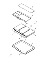
(1) Configuration of Embodiment FIG. 2 is an exploded perspective view showing a battery pack according to an embodiment of the present invention. The
[0012]
That is, the
[0013]
Here, the
[0014]
The
[0015]
Accordingly, in this embodiment, the
[0016]
FIG. 1 is an exploded perspective view showing the
[0017]
Here, the
[0018]
The
[0019]
That is, in the
[0020]
In the
[0021]
Here, as shown in FIG. 3, the
[0022]
Further, on the back surface side in FIG. 3, the insulating
[0023]
Thereby, the
[0024]
Further, the
[0025]
Further, the
[0026]
In the
[0027]
In the
[0028]
The
[0029]
(2) Operation of the embodiment In the above configuration, the battery pack 1 (FIG. 3), after the
[0030]
In this
[0031]
The
[0032]
In the
[0033]
The
[0034]
In the
[0035]
However, when the
[0036]
However, in the
[0037]
Further, since the
[0038]
Further, the
[0039]
(3) Effects of the embodiment According to the above configuration, the positive terminal and the negative terminal of the secondary battery cell are connected to both surfaces of the terminal board, respectively, and these secondary batteries are connected in series and parallel by this terminal board. Thus, the thickness can be reduced by a simple assembly operation.
[0040]
Further, in each such set, the secondary batteries are stacked so that the same surfaces face each other, so that the thickness can be reduced without accumulating uneven thickness.
[0041]
In addition, in the secondary battery cell, the positive electrode terminal and the negative electrode terminal are provided in the longitudinal direction so that a short circuit accident or the like between the stacked secondary battery cells can be effectively prevented, and further to the terminal plate. Connection work can be simplified and erroneous connection can be reliably prevented.
[0042]
In addition, by covering both sides of the wiring pattern made of a metal plate with an insulating sheet and forming a terminal plate by folding it almost in half, a terminal having connection lands on the front and back sides is reduced by reducing power loss. A board can be created.
[0043]
In addition, a wiring board equipped with a charge / discharge control circuit for controlling charging / discharging of the secondary battery cell is stacked and connected, and the power of the secondary battery cell is output to an external device through this wiring board, so that The shape can be reduced and the size can be reduced.
[0044]
(4) Other Embodiments In the above-described embodiment, the case where the terminal plate is folded in half by the slit extending in the longitudinal direction has been described. However, the present invention is not limited to this, and the bending direction is also described. Can be variously set as required.
[0045]
Further, in the above-described embodiment, the case where two secondary battery cells are connected in parallel and three of these parallel connections are connected in series has been described. However, the present invention is not limited to this, and various numbers are used. In the case of forming a parallel connection, the present invention can be widely applied to a case of connecting in series with various stages.
[0046]
In the above-described embodiment, the case where the present invention is applied to a battery pack of a personal computer has been described. However, the present invention is not limited to this and can be widely applied to battery packs of various devices.
[0047]
【The invention's effect】
As described above, according to the present invention, the positive electrode terminal and the negative electrode terminal of the secondary battery cell are connected to both surfaces of the terminal plate, respectively, and these secondary batteries are connected in series and parallel by this terminal plate, thereby simplifying assembly. It can be thinned by work.
[Brief description of the drawings]
FIG. 1 is an exploded perspective view showing a secondary battery unit of a battery pack according to an embodiment of the present invention.
FIG. 2 is an exploded perspective view of the battery pack according to the embodiment of the present invention.
FIG. 3 is a plan view for explaining a terminal plate applied to the secondary battery unit of FIG. 1;
[Explanation of symbols]
DESCRIPTION OF
Claims (3)
前記二次電池ユニットの電力を外部機器に供給可能に、前記二次電池ユニットを保持する外装ケースとを有し、
前記二次電池セルは、
1つの端面の長手方向のほぼ中央に、正極端子又は負極端子が配置されて、前記1つの端面の長手方向に順次正極端子及び負極端子が設けられ、
前記二次電池ユニットは、
前記正極端子及び負極端子が同一の側に位置して、同一面が向き合うように、複数の前記二次電池セルをそれぞれ厚み方向に積層して複数組の二次電池セルが形成され、
前記正極端子及び負極端子が同一の側に位置するように、前記長手方向に、前記複数組の二次電池セルが順次並んで配置され、
前記同一の側に位置する各二次電池セルの前記正極端子及び負極端子を、前記端子板により接続して形成され、
前記端子板は、
前記正極端子及び負極端子が設けられた前記二次電池セルの端面と平行に配置されて、
表側面と裏側面とに形成されたランドに、それぞれ前記二次電池セルの正極端子及び負極端子を接続し、前記ランド間の配線パターンにより、前記複数の二次電池セルを直並列に接続し、
前記二次電池セルが設けられた側とは逆側に配置されたコネクタを介して、前記二次電池セルの電力を外部の機器に出力する
バッテリパック。A secondary battery unit formed by connecting a plurality of secondary battery cells in a thin plate shape with a terminal plate;
An external case that holds the secondary battery unit so that the power of the secondary battery unit can be supplied to an external device;
The secondary battery cell is
A positive electrode terminal or a negative electrode terminal is arranged at substantially the center in the longitudinal direction of one end surface , and a positive electrode terminal and a negative electrode terminal are sequentially provided in the longitudinal direction of the one end surface ,
The secondary battery unit is
A plurality of sets of secondary battery cells are formed by laminating the plurality of secondary battery cells in the thickness direction so that the positive electrode terminal and the negative electrode terminal are located on the same side and face the same surface ,
The plurality of sets of secondary battery cells are sequentially arranged in the longitudinal direction so that the positive electrode terminal and the negative electrode terminal are located on the same side,
Formed by connecting the positive terminal and the negative terminal of each secondary battery cell located on the same side by the terminal plate,
The terminal board is
Arranged in parallel with the end face of the secondary battery cell provided with the positive electrode terminal and the negative electrode terminal,
A land formed on a front surface and a rear surface, respectively connect a positive terminal and a negative terminal of the secondary battery cell, the wiring pattern between the land, connecting the plurality of secondary battery cells in series-parallel ,
The electric power of the secondary battery cell is output to an external device via a connector disposed on the side opposite to the side where the secondary battery cell is provided.
Bas Tteripakku.
金属板材による配線パターンの両面を絶縁シートによりそれぞれ覆い、ほぼ2つ折りにして形成された
請求項1に記載のバッテリパック。The terminal board is
It was formed by covering both sides of the wiring pattern made of a metal plate with an insulating sheet and folding it almost in half .
The battery pack according to 請 Motomeko 1.
前記二次電池セルの充放電を制御する充放電制御回路及び前記コネクタを搭載した配線基板が積層され、前記配線基板に接続されることにより、コネクタを介して、前記二次電池セルの電力を外部の機器に出力する
請求項1に記載のバッテリパック。The terminal board is
A charge / discharge control circuit for controlling charge / discharge of the secondary battery cell and a wiring board on which the connector is mounted are stacked and connected to the wiring board, whereby the power of the secondary battery cell is supplied via the connector. Output to external device
The battery pack according to 請 Motomeko 1.
Priority Applications (6)
| Application Number | Priority Date | Filing Date | Title |
|---|---|---|---|
| JP2001393119A JP4292451B2 (en) | 2001-12-26 | 2001-12-26 | Battery pack |
| DE60238637T DE60238637D1 (en) | 2001-12-26 | 2002-12-24 | BATTERY PACK |
| CNB028262468A CN1293650C (en) | 2001-12-26 | 2002-12-24 | Battery pack |
| US10/498,861 US7595129B2 (en) | 2001-12-26 | 2002-12-24 | Battery pack having a battery unit of sheet-shaped secondary batteries connected through a terminal block |
| PCT/JP2002/013422 WO2003056643A1 (en) | 2001-12-26 | 2002-12-24 | Battery pack |
| EP02790836A EP1460698B1 (en) | 2001-12-26 | 2002-12-24 | Battery pack |
Applications Claiming Priority (1)
| Application Number | Priority Date | Filing Date | Title |
|---|---|---|---|
| JP2001393119A JP4292451B2 (en) | 2001-12-26 | 2001-12-26 | Battery pack |
Publications (3)
| Publication Number | Publication Date |
|---|---|
| JP2003197166A JP2003197166A (en) | 2003-07-11 |
| JP2003197166A5 JP2003197166A5 (en) | 2005-06-23 |
| JP4292451B2 true JP4292451B2 (en) | 2009-07-08 |
Family
ID=27600183
Family Applications (1)
| Application Number | Title | Priority Date | Filing Date |
|---|---|---|---|
| JP2001393119A Expired - Lifetime JP4292451B2 (en) | 2001-12-26 | 2001-12-26 | Battery pack |
Country Status (1)
| Country | Link |
|---|---|
| JP (1) | JP4292451B2 (en) |
Families Citing this family (11)
| Publication number | Priority date | Publication date | Assignee | Title |
|---|---|---|---|---|
| JP4250932B2 (en) * | 2002-08-30 | 2009-04-08 | ソニー株式会社 | Battery block made of non-aqueous electrolyte battery and battery pack of exchange equipment size |
| JP3972884B2 (en) | 2003-10-10 | 2007-09-05 | 日産自動車株式会社 | Assembled battery |
| JP4701658B2 (en) * | 2003-10-14 | 2011-06-15 | 日産自動車株式会社 | Battery module and battery pack |
| JP4165586B2 (en) * | 2006-08-02 | 2008-10-15 | ソニー株式会社 | Battery pack |
| CN102770983B (en) * | 2010-02-24 | 2015-01-28 | 三洋电机株式会社 | Battery module, battery system, electric vehicle, mobile body, power storage device, power supply device, and electric apparatus |
| US9198292B2 (en) * | 2012-05-08 | 2015-11-24 | Samsung Sdi Co., Ltd. | Battery pack including circuit board assembly having first circuit board connected to terminals and second circuit board connected to first circuit board |
| KR102059077B1 (en) * | 2016-06-13 | 2019-12-24 | 주식회사 엘지화학 | Battery module, battery pack comprising the battery module and vehicle comprising the battery pack |
| KR102404239B1 (en) * | 2018-09-10 | 2022-05-30 | 주식회사 엘지에너지솔루션 | ICB assembly, battery module comprising the same and method for fabricating the battery module |
| KR102393936B1 (en) * | 2018-09-10 | 2022-05-03 | 주식회사 엘지에너지솔루션 | ICB assembly, battery module comprising the same and method for fabricating the battery module |
| KR102309630B1 (en) * | 2018-09-10 | 2021-10-05 | 주식회사 엘지에너지솔루션 | ICB assembly, battery module comprising the same and method for fabricating the battery module |
| EP4152512A4 (en) * | 2021-07-30 | 2023-11-08 | Contemporary Amperex Technology Co., Limited | Battery, electrical device and method for preparing battery |
-
2001
- 2001-12-26 JP JP2001393119A patent/JP4292451B2/en not_active Expired - Lifetime
Also Published As
| Publication number | Publication date |
|---|---|
| JP2003197166A (en) | 2003-07-11 |
Similar Documents
| Publication | Publication Date | Title |
|---|---|---|
| WO2003056643A1 (en) | Battery pack | |
| TWI298557B (en) | Sensing board assembly for secondary battery module | |
| JP3662485B2 (en) | Battery pack | |
| EP2905824B1 (en) | Battery pack | |
| KR101483131B1 (en) | Battery Pack | |
| EP2760064A2 (en) | Battery pack | |
| JP4292451B2 (en) | Battery pack | |
| JP3244400B2 (en) | Battery pack | |
| KR101397025B1 (en) | Lead tab assembly and battery module with the same | |
| JP4020579B2 (en) | Battery block, battery pack and battery pack fixing structure | |
| KR20160123788A (en) | Battery pack | |
| KR102619723B1 (en) | Battery pack | |
| JP2003017026A (en) | Battery pack and manufacturing method of the same | |
| JP4139985B2 (en) | Battery pack | |
| US20140349141A1 (en) | Battery pack | |
| JP3643782B2 (en) | Pack battery | |
| US20150228960A1 (en) | Battery pack | |
| US11024929B2 (en) | Battery pack including release cover | |
| KR20150006649A (en) | Battery Pack | |
| US20230155254A1 (en) | Battery module | |
| KR102591513B1 (en) | Battery Pack | |
| JP2007250204A (en) | Battery pack | |
| JP2000114697A (en) | Mounting substrate and battery | |
| JP2004134197A (en) | Electrode tab and battery pack | |
| JP2006190520A (en) | Battery pack and cover for connecting battery pack |
Legal Events
| Date | Code | Title | Description |
|---|---|---|---|
| A521 | Written amendment |
Free format text: JAPANESE INTERMEDIATE CODE: A523 Effective date: 20041005 |
|
| A621 | Written request for application examination |
Free format text: JAPANESE INTERMEDIATE CODE: A621 Effective date: 20041005 |
|
| A131 | Notification of reasons for refusal |
Free format text: JAPANESE INTERMEDIATE CODE: A131 Effective date: 20080515 |
|
| A521 | Written amendment |
Free format text: JAPANESE INTERMEDIATE CODE: A523 Effective date: 20080620 |
|
| TRDD | Decision of grant or rejection written | ||
| A01 | Written decision to grant a patent or to grant a registration (utility model) |
Free format text: JAPANESE INTERMEDIATE CODE: A01 Effective date: 20090312 |
|
| A01 | Written decision to grant a patent or to grant a registration (utility model) |
Free format text: JAPANESE INTERMEDIATE CODE: A01 |
|
| A61 | First payment of annual fees (during grant procedure) |
Free format text: JAPANESE INTERMEDIATE CODE: A61 Effective date: 20090325 |
|
| FPAY | Renewal fee payment (event date is renewal date of database) |
Free format text: PAYMENT UNTIL: 20120417 Year of fee payment: 3 |
|
| R151 | Written notification of patent or utility model registration |
Ref document number: 4292451 Country of ref document: JP Free format text: JAPANESE INTERMEDIATE CODE: R151 |
|
| FPAY | Renewal fee payment (event date is renewal date of database) |
Free format text: PAYMENT UNTIL: 20120417 Year of fee payment: 3 |
|
| FPAY | Renewal fee payment (event date is renewal date of database) |
Free format text: PAYMENT UNTIL: 20120417 Year of fee payment: 3 |
|
| FPAY | Renewal fee payment (event date is renewal date of database) |
Free format text: PAYMENT UNTIL: 20130417 Year of fee payment: 4 |
|
| R250 | Receipt of annual fees |
Free format text: JAPANESE INTERMEDIATE CODE: R250 |
|
| FPAY | Renewal fee payment (event date is renewal date of database) |
Free format text: PAYMENT UNTIL: 20130417 Year of fee payment: 4 |
|
| FPAY | Renewal fee payment (event date is renewal date of database) |
Free format text: PAYMENT UNTIL: 20140417 Year of fee payment: 5 |
|
| R250 | Receipt of annual fees |
Free format text: JAPANESE INTERMEDIATE CODE: R250 |
|
| R250 | Receipt of annual fees |
Free format text: JAPANESE INTERMEDIATE CODE: R250 |
|
| R250 | Receipt of annual fees |
Free format text: JAPANESE INTERMEDIATE CODE: R250 |
|
| R250 | Receipt of annual fees |
Free format text: JAPANESE INTERMEDIATE CODE: R250 |
|
| R250 | Receipt of annual fees |
Free format text: JAPANESE INTERMEDIATE CODE: R250 |
|
| S111 | Request for change of ownership or part of ownership |
Free format text: JAPANESE INTERMEDIATE CODE: R313113 Free format text: JAPANESE INTERMEDIATE CODE: R313111 |
|
| R350 | Written notification of registration of transfer |
Free format text: JAPANESE INTERMEDIATE CODE: R350 |
|
| R360 | Written notification for declining of transfer of rights |
Free format text: JAPANESE INTERMEDIATE CODE: R360 |
|
| R371 | Transfer withdrawn |
Free format text: JAPANESE INTERMEDIATE CODE: R371 |
|
| S111 | Request for change of ownership or part of ownership |
Free format text: JAPANESE INTERMEDIATE CODE: R313113 |
|
| R360 | Written notification for declining of transfer of rights |
Free format text: JAPANESE INTERMEDIATE CODE: R360 |
|
| R250 | Receipt of annual fees |
Free format text: JAPANESE INTERMEDIATE CODE: R250 |
|
| R360 | Written notification for declining of transfer of rights |
Free format text: JAPANESE INTERMEDIATE CODE: R360 |
|
| R371 | Transfer withdrawn |
Free format text: JAPANESE INTERMEDIATE CODE: R371 |
|
| S111 | Request for change of ownership or part of ownership |
Free format text: JAPANESE INTERMEDIATE CODE: R313113 |
|
| R360 | Written notification for declining of transfer of rights |
Free format text: JAPANESE INTERMEDIATE CODE: R360 |
|
| R360 | Written notification for declining of transfer of rights |
Free format text: JAPANESE INTERMEDIATE CODE: R360 |
|
| R371 | Transfer withdrawn |
Free format text: JAPANESE INTERMEDIATE CODE: R371 |
|
| S111 | Request for change of ownership or part of ownership |
Free format text: JAPANESE INTERMEDIATE CODE: R313113 |
|
| R350 | Written notification of registration of transfer |
Free format text: JAPANESE INTERMEDIATE CODE: R350 |
|
| R250 | Receipt of annual fees |
Free format text: JAPANESE INTERMEDIATE CODE: R250 |