KR20200024294A - Rotary electric - Google Patents
Rotary electric Download PDFInfo
- Publication number
- KR20200024294A KR20200024294A KR1020207003202A KR20207003202A KR20200024294A KR 20200024294 A KR20200024294 A KR 20200024294A KR 1020207003202 A KR1020207003202 A KR 1020207003202A KR 20207003202 A KR20207003202 A KR 20207003202A KR 20200024294 A KR20200024294 A KR 20200024294A
- Authority
- KR
- South Korea
- Prior art keywords
- winding
- stator
- rotor
- windings
- rotational
- Prior art date
Links
- 238000004804 winding Methods 0.000 claims abstract description 300
- 230000004907 flux Effects 0.000 claims abstract description 25
- 238000010248 power generation Methods 0.000 claims description 29
- 230000005611 electricity Effects 0.000 claims description 4
- 238000000034 method Methods 0.000 claims 8
- 230000005284 excitation Effects 0.000 description 12
- 230000000052 comparative effect Effects 0.000 description 6
- 238000010586 diagram Methods 0.000 description 6
- 238000005259 measurement Methods 0.000 description 6
- 230000004048 modification Effects 0.000 description 6
- 238000012986 modification Methods 0.000 description 6
- QCWQUWUCARNNRI-UHFFFAOYSA-N 3-ethyl-5,5,8,8-tetramethyl-6,7-dihydronaphthalene-2-carbaldehyde Chemical compound CC1(C)CCC(C)(C)C2=C1C=C(C=O)C(CC)=C2 QCWQUWUCARNNRI-UHFFFAOYSA-N 0.000 description 5
- 239000003990 capacitor Substances 0.000 description 4
- XEEYBQQBJWHFJM-UHFFFAOYSA-N Iron Chemical group [Fe] XEEYBQQBJWHFJM-UHFFFAOYSA-N 0.000 description 3
- 238000013459 approach Methods 0.000 description 2
- 230000005674 electromagnetic induction Effects 0.000 description 2
- 238000004519 manufacturing process Methods 0.000 description 2
- 229910001172 neodymium magnet Inorganic materials 0.000 description 2
- 239000011347 resin Substances 0.000 description 2
- 229920005989 resin Polymers 0.000 description 2
- RYGMFSIKBFXOCR-UHFFFAOYSA-N Copper Chemical compound [Cu] RYGMFSIKBFXOCR-UHFFFAOYSA-N 0.000 description 1
- BQCADISMDOOEFD-UHFFFAOYSA-N Silver Chemical compound [Ag] BQCADISMDOOEFD-UHFFFAOYSA-N 0.000 description 1
- 230000007423 decrease Effects 0.000 description 1
- 230000000694 effects Effects 0.000 description 1
- 238000005516 engineering process Methods 0.000 description 1
- 238000009499 grossing Methods 0.000 description 1
- 230000007774 longterm Effects 0.000 description 1
- 229910052751 metal Inorganic materials 0.000 description 1
- 239000002184 metal Substances 0.000 description 1
- 230000002093 peripheral effect Effects 0.000 description 1
- 229910052709 silver Inorganic materials 0.000 description 1
- 239000004332 silver Substances 0.000 description 1
Images


Classifications
-
- H—ELECTRICITY
- H02—GENERATION; CONVERSION OR DISTRIBUTION OF ELECTRIC POWER
- H02K—DYNAMO-ELECTRIC MACHINES
- H02K1/00—Details of the magnetic circuit
- H02K1/06—Details of the magnetic circuit characterised by the shape, form or construction
- H02K1/22—Rotating parts of the magnetic circuit
- H02K1/27—Rotor cores with permanent magnets
- H02K1/2706—Inner rotors
- H02K1/272—Inner rotors the magnetisation axis of the magnets being perpendicular to the rotor axis
- H02K1/274—Inner rotors the magnetisation axis of the magnets being perpendicular to the rotor axis the rotor consisting of two or more circumferentially positioned magnets
- H02K1/2753—Inner rotors the magnetisation axis of the magnets being perpendicular to the rotor axis the rotor consisting of two or more circumferentially positioned magnets the rotor consisting of magnets or groups of magnets arranged with alternating polarity
-
- H—ELECTRICITY
- H02—GENERATION; CONVERSION OR DISTRIBUTION OF ELECTRIC POWER
- H02K—DYNAMO-ELECTRIC MACHINES
- H02K1/00—Details of the magnetic circuit
- H02K1/06—Details of the magnetic circuit characterised by the shape, form or construction
- H02K1/12—Stationary parts of the magnetic circuit
-
- H—ELECTRICITY
- H02—GENERATION; CONVERSION OR DISTRIBUTION OF ELECTRIC POWER
- H02K—DYNAMO-ELECTRIC MACHINES
- H02K1/00—Details of the magnetic circuit
- H02K1/06—Details of the magnetic circuit characterised by the shape, form or construction
- H02K1/12—Stationary parts of the magnetic circuit
- H02K1/18—Means for mounting or fastening magnetic stationary parts on to, or to, the stator structures
- H02K1/182—Means for mounting or fastening magnetic stationary parts on to, or to, the stator structures to stators axially facing the rotor, i.e. with axial or conical air gap
-
- H—ELECTRICITY
- H02—GENERATION; CONVERSION OR DISTRIBUTION OF ELECTRIC POWER
- H02K—DYNAMO-ELECTRIC MACHINES
- H02K1/00—Details of the magnetic circuit
- H02K1/06—Details of the magnetic circuit characterised by the shape, form or construction
- H02K1/22—Rotating parts of the magnetic circuit
- H02K1/27—Rotor cores with permanent magnets
- H02K1/2793—Rotors axially facing stators
-
- H—ELECTRICITY
- H02—GENERATION; CONVERSION OR DISTRIBUTION OF ELECTRIC POWER
- H02K—DYNAMO-ELECTRIC MACHINES
- H02K11/00—Structural association of dynamo-electric machines with electric components or with devices for shielding, monitoring or protection
- H02K11/01—Structural association of dynamo-electric machines with electric components or with devices for shielding, monitoring or protection for shielding from electromagnetic fields, i.e. structural association with shields
-
- H02K11/046—
-
- H—ELECTRICITY
- H02—GENERATION; CONVERSION OR DISTRIBUTION OF ELECTRIC POWER
- H02K—DYNAMO-ELECTRIC MACHINES
- H02K11/00—Structural association of dynamo-electric machines with electric components or with devices for shielding, monitoring or protection
- H02K11/20—Structural association of dynamo-electric machines with electric components or with devices for shielding, monitoring or protection for measuring, monitoring, testing, protecting or switching
- H02K11/21—Devices for sensing speed or position, or actuated thereby
- H02K11/22—Optical devices
-
- H—ELECTRICITY
- H02—GENERATION; CONVERSION OR DISTRIBUTION OF ELECTRIC POWER
- H02K—DYNAMO-ELECTRIC MACHINES
- H02K11/00—Structural association of dynamo-electric machines with electric components or with devices for shielding, monitoring or protection
- H02K11/30—Structural association with control circuits or drive circuits
-
- H—ELECTRICITY
- H02—GENERATION; CONVERSION OR DISTRIBUTION OF ELECTRIC POWER
- H02K—DYNAMO-ELECTRIC MACHINES
- H02K16/00—Machines with more than one rotor or stator
-
- H—ELECTRICITY
- H02—GENERATION; CONVERSION OR DISTRIBUTION OF ELECTRIC POWER
- H02K—DYNAMO-ELECTRIC MACHINES
- H02K21/00—Synchronous motors having permanent magnets; Synchronous generators having permanent magnets
- H02K21/12—Synchronous motors having permanent magnets; Synchronous generators having permanent magnets with stationary armatures and rotating magnets
- H02K21/14—Synchronous motors having permanent magnets; Synchronous generators having permanent magnets with stationary armatures and rotating magnets with magnets rotating within the armatures
-
- H—ELECTRICITY
- H02—GENERATION; CONVERSION OR DISTRIBUTION OF ELECTRIC POWER
- H02K—DYNAMO-ELECTRIC MACHINES
- H02K21/00—Synchronous motors having permanent magnets; Synchronous generators having permanent magnets
- H02K21/12—Synchronous motors having permanent magnets; Synchronous generators having permanent magnets with stationary armatures and rotating magnets
- H02K21/24—Synchronous motors having permanent magnets; Synchronous generators having permanent magnets with stationary armatures and rotating magnets with magnets axially facing the armatures, e.g. hub-type cycle dynamos
-
- H—ELECTRICITY
- H02—GENERATION; CONVERSION OR DISTRIBUTION OF ELECTRIC POWER
- H02K—DYNAMO-ELECTRIC MACHINES
- H02K3/00—Details of windings
- H02K3/04—Windings characterised by the conductor shape, form or construction, e.g. with bar conductors
- H02K3/12—Windings characterised by the conductor shape, form or construction, e.g. with bar conductors arranged in slots
- H02K3/16—Windings characterised by the conductor shape, form or construction, e.g. with bar conductors arranged in slots for auxiliary purposes, e.g. damping or commutating
-
- H—ELECTRICITY
- H02—GENERATION; CONVERSION OR DISTRIBUTION OF ELECTRIC POWER
- H02K—DYNAMO-ELECTRIC MACHINES
- H02K3/00—Details of windings
- H02K3/04—Windings characterised by the conductor shape, form or construction, e.g. with bar conductors
- H02K3/28—Layout of windings or of connections between windings
-
- H—ELECTRICITY
- H02—GENERATION; CONVERSION OR DISTRIBUTION OF ELECTRIC POWER
- H02K—DYNAMO-ELECTRIC MACHINES
- H02K3/00—Details of windings
- H02K3/46—Fastening of windings on the stator or rotor structure
-
- H—ELECTRICITY
- H02—GENERATION; CONVERSION OR DISTRIBUTION OF ELECTRIC POWER
- H02P—CONTROL OR REGULATION OF ELECTRIC MOTORS, ELECTRIC GENERATORS OR DYNAMO-ELECTRIC CONVERTERS; CONTROLLING TRANSFORMERS, REACTORS OR CHOKE COILS
- H02P6/00—Arrangements for controlling synchronous motors or other dynamo-electric motors using electronic commutation dependent on the rotor position; Electronic commutators therefor
- H02P6/28—Arrangements for controlling current
Abstract
역기전력의 발생을 억제하여 높은 전압을 인가하지 않고 고회전을 실현할 수 있고, 고회전을 장시간 계속하여도 회전자의 안정성을 유지할 수 있는 회전 전기를 제공한다. 전동기(14)는 복수의 영구 자석(202)이 회전 원주 R1을 따라 배치되고, 영구 자석(202)의 자극이 회전축 L1에 따른 방향을 향한 회전자(200)와, 영구 자석(202)의 자극이 향하는 방향에서 회전 원주 R1에 따라 복수의 권선이 배치된 고정자(300)를 구비한다. 고정자(300)는 회전자(200)가 제 1 권선(301)에서 제 4 권선(304)의 단부에 대향하는 때, 고정자(300)의 단부에서 고정자(300) 내로의 자로가, 회전자(200)로부터의 주 자속 방향과 교차하는 방향으로 형성된다. 회전자(200)의 회전축 L1에 따라 설치된 복수의 고정자(300a, 300b)는 권선 사이의 틈의 위치가 회전 원주 방향을 따라 어긋나 있다. 전동기(14)는 또한 발전기로 작동하도록 할 수 있다.It is possible to suppress the generation of counter electromotive force and to achieve high rotation without applying a high voltage, and to provide a rotating electric machine capable of maintaining the stability of the rotor even when the high rotation is continued for a long time. In the electric motor 14, a plurality of permanent magnets 202 are disposed along the rotation circumference R1, and the magnetic poles of the permanent magnets 202 are directed toward the direction along the rotation axis L1, and the magnetic poles of the permanent magnets 202. The stator 300 is provided with a plurality of windings arranged along the rotational circumference R1 in this facing direction. The stator 300 has a ruler into the stator 300 at the end of the stator 300 when the rotor 200 faces the end of the fourth winding 304 in the first winding 301. And in a direction intersecting with the main magnetic flux direction from 200). In the plurality of stators 300a and 300b provided along the rotation axis L1 of the rotor 200, the positions of the gaps between the windings are shifted along the rotational circumferential direction. The electric motor 14 can also be operated as a generator.
Description
본 발명은 영구 자석에 의한 회전자와 권선에 의한 고정자를 갖는 회전 전기에 관한 것이다.The present invention relates to a rotating electric machine having a rotor by permanent magnets and a stator by windings.
전동기 및 발전기 등의 회전 전기는 회전자와 고정자를 구비하고 있다. 고정자는 회전자에 대응하여 여자하는 것으로, 예를 들면, 특허 문헌 1, 2에 기재된 종래의 전동기처럼 권선의 축이 회전자를 향하도록 철심에 권선이 감겨 있고, 특허 문헌 3에 기재된 종래의 전동기와 같이 C자 모양의 철심의 일부에 권선이 감겨 마주보는 철심의 양단부 사이에, 회전자를 배치하거나 한 것이 알려져 있다.Rotating electricity such as an electric motor and a generator includes a rotor and a stator. The stator is excited to correspond to the rotor. For example, as in the conventional electric motors described in
그러나, 특허 문헌 1-3에 기재된 종래의 전동기는 고정자의 자극을 회전자의 자극이 통과할 때, 고정자 자극과 회전자의 자극이 순간 마주보는 상태가 된다. 따라서, 회전자가 회전하여 고정자 앞을 통과하면 회전자에 의한 큰 자속의 변화가 발생하기 때문에 회전자가 회전할 때 고정자에 큰 역기전력이 발생한다. 따라서, 기존의 전동기는 고정자에 의해 회전자가 회전할 때 고정자에 큰 역기전력이 발생하므로 역기전력을 거슬러 회전자를 고회전으로 하는 고전압이 필요하다.However, when the magnetic pole of a rotor passes through the magnetic pole of a stator, the conventional electric motor of patent document 1-3 will be in the state which the magnetic pole of a stator and a magnetic pole of a rotor face immediately. Therefore, when the rotor rotates and passes in front of the stator, a large magnetic flux change is generated by the rotor, and thus a large counter electromotive force is generated when the rotor rotates. Therefore, the existing motor has a high back electromotive force generated in the stator when the rotor is rotated by the stator, a high voltage is required to turn the rotor into a high rotation against the counter electromotive force.
특허 문헌 4에는 중공 원통형 코어에 권선을 한 고정자와 원주 방향으로 N 극과 S 극이 교대로 m개 배치된 영구 자석으로 구성되어, 고정자 코어에 미소 에어 갭을 통해 회전 가능하게 배치된 입구 변수를 갖는 토로 이달 코어형 작동장치가 기재되어 있다.Patent document 4 is composed of a stator wound on a hollow cylindrical core and a permanent magnet disposed m alternatingly N poles and S poles in the circumferential direction, the inlet variable is rotatably disposed in the stator core through a micro air gap A toroidal core actuator having is described.
이 특허 문헌 4에 의하면, 고정자는 회전자의 자극이 고정자 단부에 대향할 때, 고정자 단부에서 고정자 내로 자로가, 회전자에서 주 자속 방향과 교차하는 방향으로 형성된다. 따라서, 회전자가 고정자 단부를 향해 통과할 때 고정자 단부에서 고정자 내의 자로가, 회전자에서 주 자속 방향과 교차 방향이 될 것으로 권선 방향을 반경 방향에 대향한 기존의 전동기보다 자속의 변화가 작기 때문에, 특허 문헌 1 ~ 3에 기재된 종래의 전동기보다 역기전력을 작은 것으로 할 수 있다.According to this patent document 4, when the magnetic pole of the rotor opposes the stator end, the stator is formed from the stator end into the stator in a direction crossing the main magnetic flux direction at the rotor. Therefore, when the rotor passes toward the stator end, the magnetic path in the stator at the stator end will cross the main magnetic flux direction at the rotor, so that the change in magnetic flux is smaller than that of the conventional electric motors in which the winding direction is radially opposite. The counter electromotive force can be made smaller than the conventional electric motors described in patent documents 1-3.
특허 문헌 4에 기재된 토로 이달 코어형 작동장치는 자극수를 2로 한 로터 자석이 회전축을 중심으로 회전하는 로터 부분이 도시되어 있다. 그러나 로터 자석의 자극을 고정자 코일을 향해 로터부의 하우징에 회전 원주에 따라 복수의 로터 자석을 수납하고 회전시킬 때 로터 부분이 고속 회전하면 하우징에서 자석 이 원심력에 의해 코일의 방향으로 튀어나올 위험이 있다.In the toroidal core actuator described in Patent Document 4, a rotor portion in which a rotor magnet having a magnetic pole number of 2 rotates about a rotation axis is shown. However, when the rotor part is rotated at high speed when the magnetic pole of the rotor magnet is accommodated and rotated along the circumference of the rotor part in the housing of the rotor part toward the stator coil, there is a risk that the magnet may pop out of the housing in the direction of the coil by centrifugal force. .
이것은 하우징의 외부 둘레면에 오목부를 형성하고, 이 오목부에 로터 자석을 수납하고 로터 자석이 나가지 않도록 해도 로터 자석과 코일 사이를 미소 에어 갭으로 하기 때문에 뚜껑의 두께를 얇게 하면 할수록 뚜껑이 깨지기 때문이다.This is because a recess is formed in the outer circumferential surface of the housing, and the rotor magnet is accommodated in the recess and the rotor magnet is prevented from exiting, so that the lid is broken as the thickness of the lid is thinned. to be.
따라서 자극을 고정자 코일에 대향한 로터 자석을 하우징의 외주면에 수납하는 로터부에서는 로터부가 고회전이 되면 장시간의 운전 신뢰성을 유지할 수 없다.Therefore, in the rotor part which accommodates the magnetic pole which opposes a magnetic pole in the outer peripheral surface of a housing, when a rotor part becomes high rotation, it cannot maintain long-term operation reliability.
따라서 본 발명은 역기전력의 발생을 억제하여 높은 전압을 인가하지 않아도 고회전 할 수 있도록 고회전을 장시간 계속해서 회전자의 안정성을 유지할 수 있는 회전 전기를 제공하는 것을 목적으로 한다.Therefore, an object of the present invention is to provide a rotary electric machine that can maintain the stability of the rotor for a long time to maintain the high rotation so that the high rotation can be made high without suppressing the generation of back electromotive force.
본 발명의 회전 전기는 복수의 영구 자석이 하우징에 회전 원주를 따라 배치되고, 상기 영구 자석의 자극이 회전 축선에 따른 방향을 향하고 회전자와 회전 원주를 따라 배치 된 복수의 권선을 갖는 고정자를 구비하고, 상기 코일은 상기 영구 자석의 자극이 상기 권선에 향할 때, 상기 권선의 단부에서 권선 내로 자로가 상기 영구 자석에서 주 자속 방향과 교차하는 방향으로 형성되고, 상기 고정자는 상기 회전자의 회전 축선을 따라 복수로 구비되어 상기 고정자의 각각은 상기 고정자를 형성하는 권선끼리의 틈새가 회전 원주 방향으로 어긋난 위치에 배치 된 것을 특징으로 한다.The rotary electric machine of the present invention has a stator having a plurality of permanent magnets disposed in the housing along a rotational circumference, the magnetic poles of the permanent magnets facing a direction along the rotational axis and having a plurality of windings disposed along the rotor and the rotational circumference. And the coil is formed in a direction in which a magnetic path crosses the direction of the main magnetic flux in the permanent magnet at the end of the winding when the magnetic pole of the permanent magnet is directed to the winding, and the stator is the axis of rotation of the rotor. Each of the stator is provided along the plurality of the stator, characterized in that the gap between the windings forming the stator are arranged in a position shifted in the rotational circumferential direction.
본 발명의 회전 전기에 의하면, 회전자가 고정자 권선의 단부에 마주보며 통과할 때, 권선의 단부로부터 권선 내에 자로가, 회전자에서 주 자속 방향과 교차하는 방향이 될 것으로 권선 방향을 반경 방향으로 기존의 모터보다 자속의 변화가 작기 때문에 기존의 모터보다 역기전력을 작은 것으로 할 수 있다. 또한, 회전자의 영구 자석은 회전 축선에 따른 방향을 향하고 있으며, 고정자는 영구 자석의 자극이 향하는 방향의 회전 원주에 따라 권선이 배치되어 있다. 그리고 고정자는 회전자의 회전 축선을 따라 복수로 구비되어 고정자의 각각은 고정자를 형성하는 권선끼리의 간격이 회전 원주 방향으로 어긋난 위치에 배치되어 있다. 따라서 하우징에 수납 된 영구 자석은 원심력이 작용하는 방향과 자극이 권선에 향하는 방향이 다르기 때문에 영구 자석을 코일에 접근시켜 하우징에 배치하여 회전자를 고속으로 회전시켜도 영구 자석을 하우징에서 튀어나오게 하는 것을 어렵게 할 수 있다. 또한, 회전자가 고정자의 단부 사이의 틈새에서 감속 또는 정지하려고 해도 다른 고정자에서 회전 구동을 부여할 수 있다.According to the rotary electric machine of the present invention, when the rotor passes through the end of the stator winding, the winding direction from the end of the winding to the inside of the winding will be a direction that intersects the direction of the main magnetic flux in the rotor, so that the winding direction is existing in the radial direction. Because the change in magnetic flux is smaller than that of the motor, the counter electromotive force can be made smaller than that of the conventional motor. In addition, the permanent magnet of the rotor is oriented in the direction along the axis of rotation, and the stator is disposed along the rotational circumference of the direction in which the magnetic pole of the permanent magnet is directed. The stator is provided in plural along the rotation axis of the rotor, and each of the stators is disposed at a position in which the intervals between the windings forming the stator are shifted in the rotational circumferential direction. Therefore, the permanent magnet housed in the housing is different from the direction in which the centrifugal force acts and the direction of the magnetic pole toward the winding, so that the permanent magnet pops out of the housing even when the rotor is placed in the housing by rotating the rotor at high speed. It can be difficult. Further, even if the rotor attempts to decelerate or stop in the gap between the ends of the stator, the rotational drive can be given to the other stator.
또한, 본 발명의 회전 전기는 복수의 영구 자석이 하우징에 회전 원주를 따라 배치되고, 상기 영구 자석의 자극이 회전 축선에 따른 방향을 향하고 회전자와 회전 둘레에 배치 된 복수의 권선을 갖는 고정자를 구비하고, 상기 권선은 상기 영구 자석의 자극이 상기 권선에 마주볼 때, 상기 권선의 단부에서 권선 내로의 자로가, 상기 영구 자석에서 주 자속 방향과 교차하는 방향으로 형성되며, 상기 복수의 권선 단부들 사이에 보조 권선이 설치된 것을 특징으로 한다.In addition, the rotary electric machine of the present invention has a stator having a plurality of windings in which a plurality of permanent magnets are disposed along the rotational circumference of the housing, and the magnetic poles of the permanent magnets are directed in a direction along the axis of rotation and are disposed around the rotor and the rotation. And the winding has a magnetic path from the end of the winding into the winding when the magnetic pole of the permanent magnet faces the winding, and is formed in a direction crossing the main magnetic flux direction in the permanent magnet. It is characterized in that the auxiliary winding is installed between them.
본 발명의 회전 전기에 의하면, 회전자가 고정자 권선의 단부에 마주보며 통과할 때, 권선의 단부로부터 권선 내에 자로가, 회전자에서 주 자속 방향과 교차하는 방향이 될 것으로 권선 방향을 반경 방향으로 기존의 모터보다 자속의 변화가 작기 때문에 기존의 모터보다 역기전력을 작은 것으로 할 수 있다. 또한, 회전자의 영구 자석은 회전 축선에 따른 방향을 향하고 있으며, 고정자는 영구 자석의 자극이 향하는 방향의 회전 원주에 따라 권선이 배치되어 있다. 그리고 여러 권선의 단부들 사이에 보조 권선이 설치되어 있다. 따라서 하우징에 수납 된 영구 자석은 원심력이 작용하는 방향과 자극이 권선에 향하는 방향이 다르기 때문에 영구 자석을 코일에 접근시켜 하우징에 배치하여 회전자를 고속으로 회전시켜도 영구 자석을 하우징에서 튀어나오기 어렵게 할 수 있다. 또한 여러 권선의 단부들 사이에서 발생하는 자력을 보조 권선에 의해 보완할 수 있기 때문에 보조용 권선에 의해 회전자의 회전 구동력을 증강할 수 있다.According to the rotary electric machine of the present invention, when the rotor passes through the end of the stator winding, the winding direction from the end of the winding to the inside of the winding will be a direction that intersects the direction of the main magnetic flux in the rotor, so that the winding direction is existing in the radial direction. Because the change in magnetic flux is smaller than that of the motor, the counter electromotive force can be made smaller than that of the conventional motor. In addition, the permanent magnet of the rotor is oriented in the direction along the axis of rotation, and the stator is disposed along the rotational circumference of the direction in which the magnetic pole of the permanent magnet is directed. An auxiliary winding is installed between the ends of the various windings. Therefore, the permanent magnet housed in the housing is different from the direction in which the centrifugal force acts and the direction in which the magnetic poles are directed to the winding, so that the permanent magnet can be placed close to the coil and placed in the housing so that the permanent magnet can be difficult to protrude from the housing even if the rotor is rotated at high speed. Can be. In addition, since the magnetic force generated between the ends of the various windings can be compensated by the auxiliary winding, the rotational driving force of the rotor can be enhanced by the auxiliary winding.
상기 회전자는 상기 고정자를 사이에 두고 양쪽에 배치된 것으로 할 수 있다.The rotor may be disposed on both sides with the stator therebetween.
상기 고정자를 상기 회전자의 회전 원주에 따른 원호 형상의 상기 권선에 의해 형성될 수 있다. 고정자의 권선은 회전자의 회전 축선을 중심으로 하고 원주 방향을 따라 원호 형상으로 되어 고정자의 단부에서 고정자 내로의 자로를 회전에서 주 자속 방향과 교차하는 방향으로 할 수 있다.The stator may be formed by the winding of an arc shape along the rotational circumference of the rotor. The winding of the stator is centered around the axis of rotation of the rotor and arcuate along the circumferential direction so that the magnetic path from the end of the stator into the stator crosses the direction of the main magnetic flux in rotation.
상기 고정자는 상기 회전자의 회전 원주의 접선을 따라 축선이 직선상의 권선에 의해 형성된 것으로 할 수 있다. 권선을 축선이 직선상으로 하여 제작이 용이하다.The stator may be formed by a linear winding along an tangential line of the rotational circumference of the rotor. It is easy to manufacture because the winding has a straight line.
상기 고정자는 상기 회전자의 회전 중심을 둘러싼 권선이 병렬 연결된 복수체에 의해 형성되어 있어도 좋다. 권선을 병렬 연결한 복수체에 의해 형성함으로써 권선의 저항 값을 낮출 수 있다.The stator may be formed by a plural body in which windings surrounding the center of rotation of the rotor are connected in parallel. The resistance value of the winding can be lowered by forming the plurality of windings connected in parallel.
상기 권선의 단면은 회전 축선에 따른 방향의 길이가 회전 원주의 반경 방향의 길이보다 짧게 형성되어 있어도, 영구 자석을 코일의 축선에 접근시켜 배치할 수 있다.The cross section of the winding can be arranged with the permanent magnet approaching the axis of the coil, even if the length of the direction along the rotation axis is shorter than the length in the radial direction of the rotation circumference.
상기 보조 권선과 동축에 발전용 권선이 설치되어 있으면, 발전용 권선에서 전력을 발생시킬 수 있다.If a power generation winding is provided coaxially with the auxiliary winding, it is possible to generate power from the power generation winding.
상기 발전용 권선의 전류를 조정하는 회전 속도 조정부를 연결할 수 있다. 발전용 권선은 보조 권선과 동축이기 때문에 발전용 권선에 발생하는 자기장의 보조 권선을 조력하도록 작용한다. 따라서, 회전 속도 조정부에 흐르는 전류에 따라 영구 자석의 회전수를 조정할 수 있다.It is possible to connect a rotational speed adjustment unit for adjusting the current of the power generation winding. Since the power generation winding is coaxial with the auxiliary winding, it serves to assist the auxiliary winding of the magnetic field generated in the power generation winding. Therefore, the rotation speed of the permanent magnet can be adjusted according to the current flowing in the rotation speed adjusting unit.
상기 회전 속도 조정부는 상기 발전용 권선에 연결된 정류부와, 상기 정류부에서의 전류를 소비하는 소비부를 구비한 것으로 할 수 있다. 소비부가 정류부에 의해 정류된 직류를 소비하는 전류에 따라 영구 자석의 회전수를 조정할 수 있으며, 소비부에 전류를 유효하게 활용할 수 있다.The rotation speed adjusting unit may include a rectifying unit connected to the power generation winding, and a consumption unit consuming a current in the rectifying unit. The consumption part can adjust the rotation speed of the permanent magnet according to the current which consumes the direct current rectified by the rectifier, and can effectively utilize the current in the consumption part.
본 발명의 회전 전기에 의하면, 권선 방향을 반경 방향으로 기존의 모터보다 자속의 변화가 작기 때문에 기존의 모터보다 역기전력을 작은 것으로 할 수 있으므로 고전압을 인가없이 고회전 할 수 있다. 또한, 회전자를 고속으로 회전시켜도 영구 자석을 하우징에서 튀어나오기 어렵게 할 수 있다. 따라서, 본 발명의 회전 전기는 역기전력의 발생을 억제하여 높은 전압을 인가하지 않아도 고회전 할 수 있어 고회전을 장시간 계속해도 회전의 안정성을 유지할 수 있다.According to the rotary electric machine of the present invention, since the change in magnetic flux is smaller than that of a conventional motor in the radial direction of the winding, the counter electromotive force can be made smaller than that of a conventional motor, and thus high rotation can be performed without applying a high voltage. In addition, even if the rotor is rotated at a high speed, the permanent magnet can be made difficult to protrude from the housing. Therefore, the rotary electric machine of the present invention can suppress the generation of counter electromotive force and can rotate high without applying a high voltage, so that the stability of rotation can be maintained even if the high rotation is continued for a long time.
도 1은 본 발명의 실시 예 1에 따른 회전 전기로 모터를 설명하기 위한 도면이며, (A)는 전동기의 사시도, (B)는 하우징 및 차폐판을 투과 한 상태의 전동기의 사시도이다.
도 2는 도 1에 도시된 전동기의 제어 회로의 여자 회로부의 동작을 설명하기 위한 회로도이다.
도 3은 전동기의 동작을 설명하기위한 도면이며, (A)는 끝 부분이 N 극, 다른 쪽 끝 부분이 S 극을 발생하는 상태이고, 다이어그램 (B) 쪽 끝이 S 극, 다른 쪽 끝 부분이 N 극을 발생한 상태의 도면이다.
도 4는 도 1에 도시된 전동기의 회전자의 영구 자석과 고정자 권선 자력선의 상태를 설명하기 위한 도면이다.
도 5는 본 발명의 실시 예 2에 따른 회전 전기로 모터를 설명하기 위한 도면이며, (A)는 전동기의 사시도, (B)는 하우징 및 차폐판을 투과한 상태의 전동기의 사시도이다.
도 6은 본 발명의 실시 예 3에 따른 회전 전기로 모터를 설명하기 위한 도면이며, 회전자와 고정자와 센서부와 보조 권선을 나타낸 도면이다.
도 7은 도 6에 도시된 실시 예 3에 따른 전동기의 변형 예를 설명하기 위한 도면이다.
도 8은 본 발명의 실시 예 4에 따른 회전 전기로 모터를 설명하기 위한 도면이며, 회전자와 고정자와 센서부와 보조 권선과 발전용 권선을 나타내는 도면이다.
도 9는 도 8에 도시된 전동기의 발전용 권선에 연결된 회전 속도 조정부를 설명하기 위한 회로도이다.
도 10은 도 9에 나타낸 실시 예 4에 따른 전동기의 변형 예를 설명하기 위한 도면이다.
도 11은 본 발명의 실시 예 5에 따른 회전 전기로 모터를 설명하기 위한 사시도이다.
도 12는 도 11에 도시된 전동기의 고정자 권선을 휘감는 코어의 도면이다.
도 13은 도 11에 도시된 전동기의 동작을 설명하기 위한 사시도이다.
도 14는 도 13에 도시된 전동기의 상단의 고정자 및 그 고정자와 마주보는 상단 영구 자석의 도면이다.
도 15는 도 13에 도시된 전동기가 45도 회전 한 상태의 사시도이다.
도 16은 도 15에 도시된 전동기의 상단의 고정자 및 그 고정자와 마주 상단 및 중간 영구 자석의 도면이다.
도 17은 본 발명의 실시 예 6에 따른 회전 전기로 모터를 설명하기 위한 사시도이다.
도 18은 도 5에 도시된 전동기의 고정자를 단면 타원형의 권선으로 한 것이며, 고정자를 사이에 두고 반대편에 회전자를 마련한 전동기의 도면이다.
도 19는 본 실시 예의 발전기와 비교품의 발전기의 발전 전력을 측정하기 위한 측정 시스템의 구성을 나타내는 도면이다.
도 20은 도 19에 도시된 측정 시스템에 의해 측정된 입력 전력에 대한 발전 전력의 표이다.
도 21은 도 20의 표에 나타낸 각 값을 그래프로 나타낸 도면이다.1 is a view for explaining a rotary electric motor according to a first embodiment of the present invention, (A) is a perspective view of the electric motor, (B) is a perspective view of the electric motor in a state passing through the housing and the shield plate.
FIG. 2 is a circuit diagram for describing an operation of an excitation circuit part of a control circuit of the electric motor shown in FIG. 1.
3 is a view for explaining the operation of the motor, (A) is a state where the end is the N pole, the other end is generating the S pole, diagram (B) end is the S pole, the other end It is a figure of the state which produced this N pole.
4 is a view for explaining the state of the permanent magnet and stator winding magnetic lines of the rotor of the motor shown in FIG.
5 is a view for explaining a rotary electric motor according to a second embodiment of the present invention, (A) is a perspective view of the electric motor, (B) is a perspective view of the electric motor in a state passing through the housing and the shield plate.
6 is a view for explaining a rotary electric motor according to a third embodiment of the present invention, a view showing a rotor, a stator, a sensor unit and an auxiliary winding.
7 is a view for explaining a modification of the electric motor according to the third embodiment shown in FIG.
8 is a view for explaining a rotary electric motor according to a fourth embodiment of the present invention, a rotor, a stator, a sensor unit, an auxiliary winding and a power generation winding.
FIG. 9 is a circuit diagram for describing a rotation speed adjusting unit connected to a power generation winding of the electric motor shown in FIG. 8.
10 is a view for explaining a modification of the electric motor according to the fourth embodiment shown in FIG.
11 is a perspective view illustrating a rotary electric motor according to a fifth embodiment of the present invention.
12 is a view of a core wound around the stator windings of the motor shown in FIG.
FIG. 13 is a perspective view for describing an operation of the electric motor illustrated in FIG. 11.
FIG. 14 is a view of a stator at the top of the motor shown in FIG. 13 and a top permanent magnet facing the stator.
15 is a perspective view of a state in which the electric motor shown in FIG. 13 is rotated 45 degrees.
16 is a view of the stator at the top of the motor shown in FIG. 15 and the top and middle permanent magnets facing the stator.
17 is a perspective view for explaining a rotary electric motor according to a sixth embodiment of the present invention.
FIG. 18 is a diagram in which the stator of the motor shown in FIG. 5 is a cross-sectional elliptical winding, and the motor is provided with the rotor on the opposite side with the stator therebetween.
19 is a diagram illustrating a configuration of a measurement system for measuring the generated power of the generator of the present embodiment and the generator of the comparative product.
20 is a table of generated power versus input power measured by the measurement system shown in FIG. 19.
21 is a graph illustrating each value shown in the table of FIG. 20.
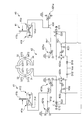
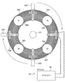
(실시 예 1) 본 발명의 실시 예 1에 따른 회전 전기에 대해 전동기를 예로 도에 따라 설명한다. 또한, 도 1 (A) 및 동 도 (B)는 본 실시 형태 1에 따른 전동기를 설명하기 위한 개략도이며, 고정자와 출력축을 지지하고, 센서부 등을 지지 할 케이스는 도시하지 않는다. 도 1 (A) 및 같은 도 (B)에 나타내는 모터(10)는 출력축(01)과 동축에 형성된 회전자(20)와 회전자(20)를 회전 구동하는 자속을 여자하는 고정자(30)를 구비하고 있다.(Example 1) A rotating electric machine according to Example 1 of the present invention will be described with reference to the drawings by way of example. 1 (A) and (B) are schematic diagrams for explaining the electric motor according to the first embodiment, and a case for supporting the stator, the output shaft, and the sensor unit is not shown. The
회전자(20)는 복수의 영구 자석(22)이 하우징(21)에 회전 원주 R1에 따라 배치된 영구 자석(22)의 N 극 또는 S 극 중 어느 한쪽의 자극이 회전 축선 L1에 따른 방향을 향하고 있다. 하우징(21)은 원반 형상으로 형성되고, 영구 자석(22)을 회전 원주 R1을 따라 일정한 간격으로 수납하는 것이다. 영구 자석(22)은 직육면체로 형성되고, N 극 또는 S 극 중 어느 한쪽의 자극을 교대로 고정자(30)를 향해 하우징(21)에 배치되어 있다. 본 실시 형태 1에서는 영구 자석(22)이 90도 마다 4 개, 하우징(21)에 설치되어 있다. 영구 자석(22)은 자력이 다른 자석보다 강력한 네오디뮴 자석을 사용할 수 있다.The
고정자(30)는 복수의 권선 C1(제1 권선(31)~ 제4 권선(34))에서 형성되고, 영구 자석(22)의 자극이 향하는 방향의 회전 원주 R1에 따라 권선(C1)이 배치되어 있다. 고정자(30)는 회전자(20)가 권선(C1)의 단부(단부(31T1,31T2,32T1,32T2,33T1,33T2,34T1,34T2))에 적합 할 때, 권선(C1)의 단부에서 권선내의 자로(R, 도 4 참조)가 회전자(20)에서 주 자속 방향 F1과 교차하는 방향으로 형성되어 있다. 본 실시 형태 1에서는 고정자(30)는 회전자(20)의 회전 축선 L1을 중심으로 권선(C1)이 회전 원주 R1에 따라 원호 형상으로 형성되어 있다.The
제1 권선(31)~ 제4 권선(34)은 제1 권선(31)의 단부(31T1)와 제4 권선(34)의 단부(34T1) 및 제어 회로(40)의 여자 회로(42)에 연결되어 마주보는 단부(31T2, 32T2)끼리, 단부(32T1,33T1)끼리 및 단부(33T2,34T2)끼리 배선에 의해 연결되는 것으로, 직렬 연결되어 있지만, 병렬 연결하여도 좋다. 제1 권선(31)~ 제4 권선(34)의 권선(C1)은 통전하면 마주보는 한쪽 단부(31T1,34T1)끼리, 단부(32T1,33T1)끼리 서로 같은 극에 다른 쪽 단부(31T2,32T2)끼리, 단부(33T2,34T2)끼리가 서로 같은 극을 발생하도록 배선이 감겨 있다.The first winding 31 to the fourth winding 34 are connected to the end 31T1 of the first winding 31, the end 34T1 of the fourth winding 34, and the
제어 회로(40)는 센서부(41)와 여자 회로(42)를 구비하고 있다. 센서부(41)는 한쪽 단부(31T1,34T1)와 단부(32T1,33T1)를 N 극으로 다른 쪽 끝 부분(31T2,32T2)와 단부(33T2,34T2)를 S 극으로 하는 타이밍을 검출하고 반대로 한쪽 단부(31T1,34T1)와 단부(32T1,33T1)를 S 극으로 하고, 다른 쪽 단부(1T2,32T2)와 단부(33T2,34T2)를 N 극으로 하는 타이밍을 감지하기 위해 제1 센서부(411)와 제2 센서부(412)를 구비하고 있다.The
제1 센서부(411) 및 제2 센서부(412)는 도시하지 않은 지지 부재에 의해 고정된 발광 다이오드와 포토 다이오드에 의한 투과형 포토 인터럽터(41a)와 회전자(20)과 함께 회전하는 투과형 포토 인터럽터(41a)의 발광 다이오드와 포토 다이오드 사이를 통과하는 원반 모양의 차폐판(41b)를 구비하고 있다.The
도 1 (A) 및 동 도 (B)에 나타내는 포토 인터럽터(41a)는 제1 센서부(411) 및 제2 센서부(412)에 대응하여 각각 설치되어 있지만, 본 실시 형태에서는 차폐판(41b)는 제1 센서부(411) 및 제2 센서부(412)에 공통시켜 설치되어 있다. 또한, 차폐판(41b)는 제1 센서부(411) 및 제2 센서부(412)에서 공통으로 사용하고 있지만, 도 2에서는 포토 인터럽터(41a)에 대응시켜 차폐판(41b)를 별도로 도시하고 있다.Although the
차폐판(41b)의 가장자리 부분에는 원주 방향을 따라 통전 시간 및 통전 시간을 규정하는 원호 형상 홈부(41c)(도 1 (A) 참조)가 형성되어 있다. 이 원호 형상 홈부(41c)는 영구 자석(22)의 N 극의 위치에 맞게 90도 사이에서 형성되고, 차폐판(41b)의 주변 2 개소에 형성되어 있다. 포토 인터럽터(41a)는 제1 권선(31) 과 제4 권선(34)가 마주보는 한쪽 단부(31T1, 34T1)의 위치를 0도 위치, 제 2 권선(32)와 제 3 권선 (33)가 마주 한쪽 단부(32T1,33T1)의 위치를 180도 위치로 한 때 0도와 90도 위치에 형성되어 있다.An arc-shaped
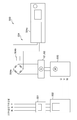
도 2에 도시된 여자 회로부(42)는 제1 권선(31) ~ 제4 권선(34)에 통전을 제어하는 것이다. 여자 회로부(42)는 제1 센서부(411)와 제2 센서부(412)와 한 쌍으로 제 1FET(421a, 421b)에서 제 3FET(423a, 423b)까지의 트랜지스터에 의해 제1 권선(31) ~ 제4 권선(34)에 통전 방향을 제어한다.The
제1 FET(421a) 및 제3 FET(423a)는 η형 FΕT이다. 제2 FΕT(422a, 422b)는 ρ형 FET이다. 제1 FΕT(421a, 421b)는 게이트 단자(G)가 저항(R11, R12)를 통해 포토 인터럽터(41a)에 연결되어 있다. 또한 제1 FET(421a, 421b)는 소스 단자(S)가 접지되어 있다.The
제2 FET(422a, 422b)는 소스 단자(S)가 다이오드(D11, D12)을 통해 전원에 연결되어 있는 동시에, 콘덴서(C11,012)를 통해 접지되어 있다. 또한 제2 FET(422a, 422b)의 게이트 단자(G)는, 저항(R21, R22)을 통해 제1 FET(421a, 421b)의 드레인 단자 (D)에 연결되어 있는 동시에, 저항(R31, R32)을 통해 제2 FΕT(422a, 422b) 소스 단자(S)에 연결되어 있다. 제2 FET(422a, 422b)의 드레인 단자(D)는 다이오드(D21, D22)의 양극 단자 A에 연결되어 있는 동시에, 제3 FET(423a, 423b)의 드레인 단자 (D)에 연결되어 있다.The
제3 FET(423a, 423b)는 게이트 단자(G)가 저항(R41, R42)를 통해 포토 인터럽터(41a)에 연결되어 있다. 제3 FET(423a, 423b) 소스 단자(S)는 접지되어 있다. 제4 권선(34)의 한쪽 단부(34T1)에서의 배선은 제 2 FΕT(422a)의 드레인 단자(D)에 연결되어 있는 동시에, 제3 FET(423a)의 드레인 단자 (D)에 연결되어 있다. 제1 권선(31)의 한쪽 단부(31T1)에서의 배선은 제2 FET(422b)의 드레인 단자(D)에 연결되어 있는 동시에, 제3 FET(423b)의 드레인 단자(D)에 연결되어 있다.In the
이상과 같이 구성된 본 발명의 실시 예 1에 따른 전동기(10)의 동작을 도를 참조하여 설명한다. 도 1 (A) 및 동 도 (B)에 나타내는 제어 회로(40)에 전원이 공급된다. 예를 들어, 영구 자석(22)의 N 극이 제1 센서부(411)의 포토 인터럽터(41a)의 방향으로 향하면, 제1 센서부(411)의 포토 인터럽터(41a)에 차폐판(41b)의 원호 형상 홈부(41c)가 위치한다. 차폐판(41b)의 원호 형상 홈부(41c)에 의해 제1 센서부(411)의 포토 인터럽터(41a)의 빛이 투과하여 제1 센서부(411)의 포토 인터럽터(41a)의 포토 트랜지스터가 통전된다.The operation of the
도 2에 나타낸 바와 같이, 제1 센서부(411)의 포토 트랜지스터가 통전하여 포토 인터럽터(41a)에 저항(R11, R41)을 통해 연결된 제1 FΕT(421a)의 게이트 단자(G)와 제3 FET(423a)의 게이트 단자(G)는 제 1 FΕT(421a) 및 제3 FΕT(423a)와는 온 상태가 되는 제 1 전압이 된다.As shown in FIG. 2, the gate transistor G and the third gate terminal G of the
또한, 도 3 (A)에 나타낸 바와 같이, 제1 센서부(411)의 포토 인터럽터(41a)에 원호 형상 홈부(41c)가 있는 경우에는 제2 센서부(412)의 포토 인터럽터(41a)는 원호 형상 홈부(41c)에 위치하지 않기 때문에, 제2 센서부(412)의 포토 인터럽터(41a)는 비 통전 상태에 있다. 따라서, 도 2에 나타낸 바와 같이, 제2 센서부(412)의 포토 인터럽터(41a)에 저항(R12, R42)을 통해 연결된 제1 FΕT(421b)의 게이트 단자(G)와 제3 FET(423b)의 게이트 단자(G)는 제1 FΕT(421b)과 제3 FΕT(423b)가 오프 상태가 되는 제 1 전압보다 낮은 전압의 제2 전압(0V)이 된다.As shown in FIG. 3A, when the
제1 FΕT(421b)가 오프 상태 인 경우에는 제1 FET(421b)의 드레인 단자(D)에 저항 R21을 통해 연결된 제2 FΕT(422a)의 게이트 단자(G)는 전원(Vss)에 연결된 저항 R31에 의해 제2 FET(422a)가 오프 상태가 되는 제1 전압이 된다.When the
제1 FΕT(421a)가 온 상태 인 경우에는 저항 R22이 제1 FΕT(421a)의 드레인 단자(D)에 연결되어 있기 때문에, 제2 FET(422b)의 게이트 단자(G)는 제2 FΕT(422b)가 ON 상태가 되고, 제2 전압이 된다.When the
이렇게 하여 제1 FET(421a, 421b) ~ 제3 FΕT(423a, 423b)의 온 상태와 오프 상태가 결정되면 전원(Vss)의 전류가 제2 FET(422b) 소스 단자(S)의 다이오드(D12)을 통해 흘러 들어 제2 FET(422b) 드레인 단자(D)에서 제1 권선(31)의 한쪽 단부(31T1)에 흐른다. 그리고 전류가 제1 권선(31)로부터 제2 권선(32), 제 3 권선(33) 및 제4 권선(34)에 순차적 흘러 제4 권선(34)의 한쪽 단부(34T1)에서 제3 FET(423a)의 드레인 단자(D) 로 흐르고, 제3 FET(423a)의 드레인 단자(D)에서 소스 단자(S)에 흐른다. 이렇게 하면,도 3 (A)에 나타낸 바와 같이, 제1 권선(31)의 단부(31T1), 제4 권선(34)의 단부(34T1), 제2 권선(32)의 단부(32T1), 제3 권선(33)의 단부(33T1)에 영구 자석(22)의 N 극과 반발로 극(N 극)의 자계가 발생하고 다른 단부(31T2), 단부(32T2)와 단부(33T2), 단부(34T2)에 영구 자석(22)의 S 극과 반발이 극(S 극)의 자기장이 발생한다. 제1 권선(31) ~ 제4 권선(34)이 발생한 자기장에 의해 영구 자석(22)의 양극이 반발하여 회전자(20)가 회전한다.In this way, when the on state and the off state of the
한편 도 3(B)에 나타낸 바와 같이, 센서부(41) 중 제2 센서부(412)의 포토 인터럽터(41a)에 차폐판(41b)의 원호 형상 홈부(41c)가 위치한다. 차폐판(41b)의 원호 형상 홈부(41c)에 의해 제2 센서부(412)의 포토 인터럽터(41a)의 빛이 투과하여 제2 센서부(412)의 포토 인터럽터(41a)의 포토 트랜지스터가 통전한다.3B, the arc-shaped
도 2에 나타낸 바와 같이, 제2 센서부(412)의 포토 트랜지스터가 통전하여 포토 인터럽터(41a)에 저항 R12, R42을 통해 연결된 제1 FΕT(421b)의 게이트 단자(G)와 제3 FET(423b)의 게이트 단자(G)는 제1 FΕT(421b) 및 제3 FΕT(423b)과 온 상태가 되는 제 1 전압이 된다.As shown in FIG. 2, the gate transistor G and the third FET of the
또한 제2 센서부(412)의 포토 인터럽터(41a)에 원호 형상 홈부(41c)가 있는 경우에는 제1 센서부(411)의 포토 인터럽터(41a)는 원호 형상 홈부(41c)가 위치하지 않기 때문에, 제1 센서부(411)의 포토 인터럽터(41a)는 비 통전 상태에 있다. 따라서, 제1 센서부(411) 포토 인터럽터(41a)에 저항 R11, R41을 통해 연결된 제1 FET(421a)의 게이트 단자(G)와 제3 FET(423a)의 게이트 단자(G)는 제1 FΕT(421a) 및 제3 FΕT(423a)가 오프 상태가 되어 제2 전압이 된다.In addition, when the
제1 FΕT(421a)가 오프 상태 인 경우에는 제1 FΕT(421a)의 드레인 단자(D)에 저항 R22을 통해 연결된 제2 FΕT(422b)의 게이트 단자(G)는 전원(Vss)에 연결된 저항 R32에 의해 제2 FET(422b)가 오프 상태가 되는 제 1 전압이 된다.When the
제1 FΕT(421b)가 온 상태 인 경우에는 저항 R21이 제1 FΕT(421b)의 드레인 단자(D)에 연결되어 있기 때문에, 제2 FET(422a)의 게이트 단자(G)는 제2 FΕT(422a)가 온 상태가 되는 제2 전압이 된다.When the
이렇게 하여 제1 FET(421a, 421b)~ 제3 FΕT(423a, 423b)의 온 상태와 오프 상태가 결정되면 전원(Vss)의 전류가 제2 FΕT(422a)의 소스 단자(S) 다이오드(D11)을 통해 흘러 들어 제2 FET(422a)의 드레인 단자(D)에서 제4 권선(34)의 한쪽 단부(34T1)에 흐른다. 그리고 전류가 제4 권선(34)로부터 제 3 권선(33) 제2 권선(32) 및 제1 권선(31)로 순차적으로 흘러 제1 권선(31)의 한쪽 단부(31T1)에서 제3 FET(423b)의 드레인 단자(D)로 흐르고, 제3 FET(423b)의 드레인 단자(D)에서 소스 단자(S)에 흐른다. 이렇게 하면, 도 3 (B)에 나타낸 바와 같이, 제1 권선(31)의 단부(31T1), 제4 권선(34)의 단부(34T1), 제2 권선(32)의 단부(32T1), 제3 권선(33)의 단부(33T1)과 영구 자석(22)의 S 극과 반발되어 극(S 극)의 자계가 발생하고 다른 단부(31T2), 단부(32T2)와 단부(33T2), 단부(34T2)에 영구 자석(22)의 N 극과 반발하는 같은 극(N 극)의 자기장이 발생한다. 제1 권선(31)~ 제4 권선(34)이 발생한 자기장에 의해 영구 자석(22)의 양극이 반발하여 회전자(20)가 회전한다.In this way, when the on state and the off state of the
또한, 회전자(20)가 회전하면 차폐판(41b)에 형성된 다른 원호 형상 홈부(41c)는 제1 센서부(411)의 포토 인터럽터(41a)에 위치하여 고정자(30)에서 도 3(A)에 나타내는 자극의 자계가 발생한다. 이와 같이, 고정자(30)에 있어서, 도 3 (A)에 나타내는 자극과 도 3 (B)에 나타내는 자극이 교대로 발생하여 회전자(20)는 계속 회전할 수 있다.In addition, when the
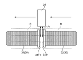
전동기(10)는 고정자(30), 회전자(20)의 회전 축선 L1을 중심하여 제1 권선(31) ~ 제4 권선(34)이 원주 방향을 따라 원호 형상으로 형성되어 있다. 따라서 도 4와 같이 고정자(30) 내의 자로는 권선(제1 권선(31)~ 제4 권선(34))의 원호 형상에 따른 것이 된다. 회전자(20)의 영구 자석(22)의 각 자극이 제1 권선(31)~ 제4 권선(34)의 단부(도 4는 제1 권선(31)의 단부(31T1), 제4 권선(34)의 34T1)을 향하고 통과할 때, 고정자(30)의 단부로부터 고정자(30) 내에 자로가, 회전자(20)의 주 자속 방향 F1과 교차하는 방향이 된다. 따라서, 회전자(20)에서 주로 자속은 권선(C1) 통내에 똑바로 들어가게 횡단하지 않는다. 따라서, 전동기(10)는 권선 방향을 반경 방향으로 기존의 모터보다 자속의 변화가 작기 때문에 기존의 모터보다 역기전력을 작은 것으로 할 수 있다.As for the
또한, 도 1에 나타낸 바와 같이, 회전자(20)의 영구 자석(22)은 회전 축선 L1에 따른 방향을 향하고 있으며, 고정자(30)는 영구 자석(22)의 자극이 향하는 방향에 있어서 회전 원주 R1에 따라 권선(C1)이 배치되어 있다. 따라서 하우징(21)에 수납 된 영구 자석(22)은 원심력이 작용하는 방향(회전 원주 R1의 반경 방향)과 자극이 권선(C1)을 향한 방향이 다른 방향이 되므로, 영구 자석(22)의 권선(C1)에 접근시켜 하우징(21)에 배치하고, 회전자(20)를 고속으로 회전 시켜도 하우징(21)로부터 영구 자석(22)이 튀어나가는 것을 어렵게 할 수 있다. 따라서, 회전자(20)의 고속 회전을 유지 한 상태에서 장시간 운전을 가능하게 할 수 있다.In addition, as shown in FIG. 1, the
따라서, 본 실시 형태 1에 따른 전동기(10)는 역기전력의 발생을 억제하여 높은 전압을 인가하지 않아도 고회전 할 수 있어, 고회전을 장시간 계속해서 회전자(20)의 신뢰성을 유지할 수 있다.Therefore, the
본 실시 형태 1에서는 도 1 (B)에 나타낸 바와 같이, 제1 권선(31) ~ 제4 권선(34)이 회전 원주 R1에 따라 원호 형상으로 형성되고, 고정자(30)로 원형에 배치되어 있지만, 고정자의 단부에서 고정자 내로 자로가, 회전자에서 주 자속 방향과 교차하는 방향이 되면, 회전 원주보다 곡률이 크게 형성되어 있거나, 작게 형성되어 있거나 하고 있다. 또한 영구 자석의 자극이 향한 방향에 대해 권선의 길이 방향의 중심이 직교하지 않고 경사져 있어도 좋다.In the first embodiment, as shown in FIG. 1B, the
(실시 예 2) 본 발명의 실시 예 2에 따른 회전 전기에 대해 전동기를 예로 도에 따라 설명한다. 또한, 도 1 (A) 및 동 도 (B)와 마찬가지로, 도 5 (A) 및 동 도 (B)에도 고정자와 출력축, 센서부 등을 지지하는 케이스는 도시하지 않는다. 또한, 도 5 (A) 및 동 도 (B)에 있어서는, 도 1 (A) 및 동 도 (B)와 같은 구성은 같은 부호를 붙이고 설명을 생략한다. (Second Embodiment) A rotating electric machine according to a second embodiment of the present invention will be described with reference to the drawings by way of example. 1 (A) and (B), the case supporting the stator, the output shaft, the sensor part, and the like is not shown in FIGS. 5A and 5B. In addition, in FIG. 5 (A) and FIG. (B), the structure similar to FIG. 1 (A) and FIG. (B) attaches | subjects the same code | symbol, and abbreviate | omits description.
본 실시 예 2에 따른 전동기(11)는 고정자(30a)의 권선(C2)이 영구 자석(22)의 자극이 향하는 방향의 회전 원주 R1을 따라 배치되어 있다. 또한 권선(C2)는 회전자(20)의 회전 원주 R1의 접선을 따라 축선 L2가 직선으로 형성되어 있다. 이와 같이 고정자(30a)의 권선(C2)의 축선 L2가 직선으로 형성되어 있고, 영구 자석(22)이 권선(C2)의 단부에 적합 할 때, 권선(C2)의 단부에서 권선(C2) 내에 자로가 영구 자석(22)로부터 주 유동 방향과 교차하는 방향으로 고정자(30a)의 권선(C2)가 형성되어 있으며, 그리고 영구 자석(22)의 자극이 향하는 방향의 회전 원주 R1에 따라 권선(C2)가 배치되어 있다. 따라서 실시 예 1과 동일한 작용 효과를 얻을 수 있다.In the
또한 권선(C2)의 축선 L2가 직선으로 형성되어 있기 때문에 코어에 선재를 감을 때 원호상의 권선 C1(도 1 참조)과 비교하여 균등하게 감기가 쉽다. 따라서, 축선 L2가 직선상으로 감기는 권선(C2)는 작업성을 향상시킬 수 있다.In addition, since the axis L2 of the winding C2 is formed in a straight line, it is easier to wind evenly compared to the winding C1 (see Fig. 1) in the shape of an arc when the wire is wound around the core. Therefore, the winding C2 in which the axis L2 is wound in a straight line can improve workability.
예를 들어, 축선 L2가 선형 권선(C2)한 고정자(30a) 인 경우, 회전자의 영구 자석의 자극을 회전 반경 방향의 바깥쪽으로 향해 고정자(30a)의 권선(C2)로 둘러싸인 중앙부에 배치하면 영구 자석의 자극과 권선(C2)와의 거리가 권선(C1)의 몸통에 접근하고 단부에서 떨어져 버려, 일정 되지 않는다. 그러나, 전동기(11)는 회전 원주 R1에 따라 배치된 권선(C2)의 위쪽으로, 회전자(20)의 영구 자석(22)이 회전하는 영구 자석(22)의 자극과 권선(C2)와의 거리를 일정하게 할 수 있다.For example, in the case where the axis L2 is the
(실시 예 3) 본 발명의 실시 예 3에 따른 회전 전기에 대해 전동기를 예로 도에 따라 설명한다. 도 6에 도시된 본 실시 예 3에 따른 전동기(12)는 도 1 (A) 및 동 도 (B)에 나타내는 실시 예 1에 따른 전동기(10)의 보조 권선(33a~33d)을 갖춘 것이다. 또한, 도 6에서는 도 1 (A) 및 동 도 (B)와 같은 구성으로는 같은 부호를 붙이고 설명을 생략한다. (Third Embodiment) A rotary electric machine according to a third embodiment of the present invention will be described with reference to the electric motor as an example. The
도 6에 나타낸 바와 같이, 보조 권선(33a~33d)은 직접 관에 형성된 자력 증강 용 권선이다. 권선(33a~33d)는 제1 권선(31)~ 제4 권선(34)의 각각의 마주 보는 단부끼리(단부(31T1)와 단부(34T1), 단부(31T2)와 단부(32T2), 단부(32T1)와 단부(33T1), 단부(33T2)와 단부(34T2)의 바깥쪽으로 권선(33a~33d) 축선을 회전 원주의 반경 방향으로 배치되어 있다. 권선(33a)는 단부(31T1) 및 단부(34T1)와 동극이 되도록 권선(33b)는 단부(31T2) 및 단부(32T2)와 동극이 되도록, 또한 권선(33c)는 단부(32T1) 및 단부(32T1)와 동극이 되도록 더욱 권선(33d)는 단부(33T2) 및 단부(34T21)와 동극이 되도록 제어 회로(40)에 의해 제어된다.As shown in Fig. 6, the
복수의 권선(제1 권선(31)~ 제4 권선(34))끼리의 사이의 보조 권선(33a~33d)이 축선을 향해 권선 단부가 발생하는 자극과 같은 극을 발생하도록 설치되어 있는 것으로, 제1 권선(31) ~ 제4 권선(34)의 각각의 단부에 의한 자력을 권선(33a~33d)에 의해 보완될 수 있다. 따라서, 권선(33a~33d)하여 회전자(20)의 회전 구동력을 증강할 수 있다.The
(실시 예 3의 변형 예) 본 실시 형태 3에 따른 전동기의 변형 예를 도에 따라 설명한다. 도 7에 도시된 본 실시 형태 3에 따른 전동기(12a)는 도 6에 나타낸 실시 예 3에 따른 전동기(12)의 보조 권선(33a~33d) 축선 L3를 회전 축선 L1에 따라 회전자(20) 쪽을 향한 것이며, 고정자(30a)의 권선(C2)가 직선 축선 L2에 형성된 것이다. 또한, 도 7에 있어서는, 도 5 (A) 및 동 도 (B) 및 도 6과 동일한 구성의 것은 같은 부호를 붙이고 설명을 생략한다.(Modification of Embodiment 3) A modification of the electric motor according to
이와 같이 보조 권선(33a~33d)에 대해 그 축선 L3를 회전 축선 L1에 따라 회전자(20)쪽으로 돌리면 권선(33a~33d)에서 자속이 회전자(20)의 방향으로 향한다. 따라서 권선(33a~33d)에 따라 제1 권선(31)~ 제4 권선(34)의 각각의 단부에 의한 자력을 더 강력하게 보강할 수 있다.In this manner, when the axis L3 is turned toward the
(실시 예 4) 본 발명의 실시 예 4에 따른 회전 전기에 대해 전동기를 예로 도에 따라 설명한다. 도 8에 나타낸 본 실시 예 4에 따른 전동기(13)는 도 6에 나타낸 실시 예 3에 따른 전동기(12)에 발전용 권선(35a~35d)을 갖춘 것이다. 또한, 도 8에서는 도 6과 같은 구성의 것은 같은 부호를 붙이고 설명을 생략한다.Fourth Embodiment A rotating electric machine according to a fourth embodiment of the present invention will be described with reference to the drawings by way of example. The
도 8에 나타낸 바와 같이, 전동기(13)의 보조 권선(33a~33d)와 동축으로 발전용 권선(35a~35d)가 설치되어 있다. 발전용 권선(35a~35d)에는 도 9와 같이 회전 속도 조정부(50)가 연결되어 있다. 회전 속도 조정부(50)는 정류부(51)와 소비부(52)를 구비하고 있다. 정류부(51)는 다이오드 브릿지로 구성할 수 있다. 소비부(52)는 가변 저항기로 할 수 있지만, 가변 저항기 대신 전기 에너지를 활용하는 부하를 연결하고 있다. 예를 들어, 배터리 충전 회로로 하고, 조명기구로 하고, 전동기로 할 수 있다. 소비부(52)는 단락 상태에서 개방 상태까지 저항 값을 설정할 수 있는 것으로 할 수 있다. 회전 속도 조정부(50)는 발전용 권선(35a~35d)의 각각에 마련할 수 있으며, 발전용 권선(35a~35d)에 공통시켜 마련할 수도 있다.As shown in FIG. 8, the
다음 발전용 권선(35a~35d)에서 전류를 조정하는 회전 속도 조정부(50)의 동작에 대해 상세하게 설명한다. 도 8에 도시된 전동기(13)를 동작시켜, 권선(33a~33d)에 통전하여 발전용 권선(35a~35d)에 기전력을 발생시킬 수 있다. 도 9에 도시 발전용 권선(35a~35d)에서 전류는 정류부(51)에 의해 전파 정류된 소비부(52)에 흐른다. 소비부(52)는 발전용 권선(35a~35d)에서 전력을 설정된 저항에 의해 소모한다.Next, the operation of the rotation
소비부(52)의 소비 전류가 커지면 권선(33a~33d)와 동축에 배치된 발전용 권선(35a~35d)은, 권선(33a~33d)에 의한 전자기 유도보다 회전자(20)의 영구 자석(22)에 의한 전자기 유도 쪽이 커지고 발생한 전류는 권선(33a~33d)을 조력하는 자계를 발생한다.If the current consumption of the
이 때, 권선(33a~33d)에 입력 전압을 일정하게 하여 소비부(52)가 발전용 권선(35a~35d)에서 꺼낼 출력 전류를 크게 하면 소비부(52)의 출력 전압은 저하하지만, 회전자(20)의 회전수는 소비 전류(출력 전류) 0A에서의 전류까지 저하하지만, 그후 천천히 빨라진다.At this time, if the input voltage is made constant to the
이와 같이, 전동기(13)의 회전 속도 조정부(50)에 의해 전류를 조정하여 회전수를 조정할 수 있기 때문에, 전동기(13)는 회전수를 제어할 수 있는 신규 전동기로 할 수 있다.Thus, since the rotation speed can be adjusted by adjusting the electric current by the rotation
또한, 소비부(52)는 정류부(51)을 통해 연결되어 있었지만, 소비부(52)를 단락 상태로 하는 경우에는 정류부(51)는 생략할 수 있다.In addition, although the
(실시 예 4의 변형 예) 본 실시 예 4에 따른 전동기의 변형 예를 도에 따라 설명한다. 도 10에 도시된 본 실시 예 4에 따른 전동기(13a)는 도 8에 나타낸 실시 예 4에 따른 전동기(12)의 보조 권선(33a~33d) 및 발전용 권선(35a~35d)의 축선 L3을 회전시 축선 L1에 따라 회전자(20) 쪽을 향한 것이며, 고정자(30a)의 권선(C2)가 직선 축선 L2에 형성된 것이다. 또한, 도 10에서 도 5 (A) 및 동 도 (B) 및 도 8과 동일한 구성의 것은 같은 부호를 붙이고 설명을 생략한다.(Modification of Embodiment 4) A modification of the electric motor according to Embodiment 4 will be described with reference to the drawings. The
이와 같이 보조 권선(33a~33d) 및 보조 권선(33a~33d)와 동축에 배치된 발전용 권선(35a~35d)에 대해 그 축선 L3을 회전 축선 L1에 따라 회전자(20) 쪽으로 조준하면 권선(33a~33d)에서 자속이 회전자(20)의 방향으로 향한다. 따라서 권선(33a~33d) 따라 제1 권선(31)~ 제4 권선(34)의 각각의 단부에 의한 자력을 더 강력하게 보강할 수 있어 보조 권선(33a~33d)에서 자력에 의해 발전용 권선(35a~35d)로 발전시킬 수 있다.As described above, with the
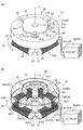
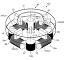
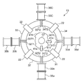
(실시 예 5) 본 발명의 실시 예 5에 따른 회전 전기 대해 전동기를 예로 도에 따라 설명한다. 또한, 도 11 내지 도 16은 본 실시 예 5에 따른 전동기를 설명하기 위한 개략도이며, 고정자와 출력축을 지지하고, 센서부 등을 지지 할 케이스는 도에 도시되어 있지 않다. 또한, 회전자의 영구 자석을 유지하고 회전 축선을 중심으로 회전 하우징은 도시하지 않는다. 또한, 여자 회로(42) (도 2 참조)은 같은 것이 사용될 수 있기 때문에 설명은 생략한다.Fifth Embodiment A rotary electric motor according to a fifth embodiment of the present invention will be described with reference to the drawings. 11 to 16 are schematic views for explaining the electric motor according to the fifth embodiment, and a case for supporting the stator, the output shaft, and the sensor unit is not shown in the figure. In addition, the rotating housing is not shown around the axis of rotation holding the permanent magnet of the rotor. In addition, since the same thing can be used for the excitation circuit 42 (refer FIG. 2), description is abbreviate | omitted.
도 11에 나타낸 바와 같이, 본 실시 예 5에 따른 전동기(14)는 회전자(200)의 원주의 영구 자석(202)의 N 극 또는 S 극 중 어느 한쪽의 자극이, 회전자(200)의 회전 축선 L1에 따른 방향을 향하고 있어 고정자(300)는 회전자(200)의 자극이 향하는 방향의 회전 원주 R1을 따라 배치되어 있다. 회전자(200)는 고정자(300)를 사이에 두고 상하 방향의 양쪽에 배치되어 출력축(O1)에 연결되어 있다. 본 실시 예 5에 따른 전동기(14)에서는, 회전자(200)가 상하 방향을 따라 상단(제1 회전자(200a), 중간 (제2 회전자(200b), 하단(제 3 회전자(200c)의 3 가지를 갖추고 있다. 따라서 각각의 회전자(200)의 사이에 고정자(300)가 상단(제 1 고정자(300a) 및 하단(제 2 고정자(300b)의 2개 배치되어 있다. 따라서, 상단의 고정자(300)(제 1 고정자(300a)은 상단 및 중간 회전자(200)(제 1 회전자(200a), 제 2 회전자(200b)에 의해 끼워져 있으며, 하단의 고정자(300)(제 2 고정자(300b)는 중간과 하단의 회전자(200)(제 2 회전자(200b), 제 3 회전자(200c)에 의해 끼워져 있다.As shown in FIG. 11, in the
회전자(200)의 각각의 영구 자석(202)은 회전 축선 L1에 따른 방향에서 볼 때 같은 위치에 배치되어 있다. 상단의 회전자(200)(제1 회전자(200a)은 영구 자석(202)의 N 극과 S 극이 교대로 하향 고정자(300) 쪽을 향하도록 배치되어 있다. 중간의 회전자(200)(제2 회전자(200b)의 위쪽을 향 자극(상단의 회전자(200)의 영구 자석(202)과 마주 자극)은 상단의 회전자(200)와 같은 극이 되도록 배치되어 있다. 또한 중간의 회전자(200)의 하부로 향하는 자극은 중간의 회전자(200)의 위쪽을 향 자극과 반대의 자극이다. 하단의 회전자(200)(제 3 회전자(200c)의 위쪽을 향 자극(중간의 회전자(200)의 영구 자석(202)과 마주 자극)은 중간의 회전자(200)의 아래쪽을 향 자극과 같은 극이 되도록 배치되어 있다.Each
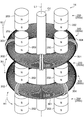
고정자(300)의 권선(301~304)은 회전 축선 L1에 따라 여러 갖추고 있으며, 상단의 고정자(300)(제1 고정자(300a)와 하단의 고정자(300)(제2 고정자(300b)의 각각은 권선(301~304) 사이의 틈새가 회전 원주 방향으로 45도 어긋난 위치에 배치되어 있다. 고정자(300)는 회전자(200)의 회전 축선 L1을 중심으로 원주 방향을 따라 원주를 4 분할 된 원호상의 권선(301~304)이 도 12에 도시된 코어(310)에 감아 돌아 형성되어 있다.The
도 12에 도시된 코어(310)는 양방향 단부에 위치하는 원반 모양의 차양부(311)와, 차양부(311)의 사이를 이어가고, 주위에 권선(301~304)을 감아 돌린 심재(312)에 의해 형성되어 있다. 코어(310)는 금속으로 할 수도 있지만 수지제로 할 수도 있다. 코어(310)를 수지제로 하면 자기 포화가 발생하지 않기 때문에 권선(301~304)에 대전류를 흘릴 때 바람직하다.The
이 고정자(300)는 도 14에 나타낸 바와 같이, 각각의 권선(301~304)이 연결선(305)에 의해 연결되어 있는 것으로서 직렬 접속되어 있다. 그리고 직렬 접속된 고정자(300)(권선 301~304)의 양단에서의 배선은 제어 회로(40)의 여자 회로(42)에 접지 되어있다. 고정자(300)의 권선(301~304)은 여자 회로(42)에 의해 마주보는 단부끼리가 같은 극을 발생하도록 배선이 감겨 있다.As shown in FIG. 14, the
도시하지 않은 센서부는 실시 예 1의 센서부(41)(도 1 참조)과 마찬가지로 투과형 포토 인터럽터와 포토 인터럽터를 통과하는 오프 아웃부를 갖는 차폐판을 구비한 것으로 할 수 있다. 이러한 센서부로 하여 회전자(200)의 영구 자석(202)의 위치를 검출할 수 있다. 본 실시 예 5에서는 고정자(300)가 4개의 권선(301~304)을 갖춘 제1 고정자(3OOa) 및 제2 고정자(300b) 및 회전 둘레에 45도 차이로 한 것이기 때문에 권선(301~304)의 단부끼리 마주한 4개소를 감지하도록 형성되어 있다.Like the sensor part 41 (refer FIG. 1) of Example 1 which is not shown in figure, it can be provided with the shielding plate which has a transmissive photo interrupter and the off-out part which passes through a photo interrupter. Such a sensor unit can detect the position of the
이상과 같이 구성된 본 발명의 실시 예 5에 따른 전동기(14)의 동작을 도를 참조하여 설명한다. 도 13 및 도 14에 나타낸 바와 같이, 먼저 초기 상태로 상단의 회전자(200)(제1 회전자(200a)은 영구 자석(202) 상단의 고정자(300) (제1 고정자 3OOa)의 권선(301 ~304) 중심부 부근에 위치하고 있지만, 중간의 회전자(제 2 회전자(200b)과 하단(제 3 회전자(200c)은 영구 자석(202) 하단의 고정자(300)(제 2 고정자(300b)의 권선(301~304)의 단부 부근에 위치하고 있다.The operation of the
센서부가 하단의 고정자(300)의 권선(301~304)의 단부 부근에 중단 회전자(제 2 회전자(200b)과 하단(제3 회전자(200c)가 위치하고 있음을 감지하면, 여자 회로부(42)는 상단의 고정자(300)(제1 고정자(300a)에 대해 권선(301), 권선(302)이 마주하는 단부끼리 N 극 권선(302)과 권선(303)이 마주하는 단부 끼리 S 극 권선(303), 권선(304)과 마주하는 단부끼리 N 극 권선(304)과 권선(301)이 마주하는 단부끼리 S 극이 되도록 통전한다. 또한 여자 회로부(42)는 도 13에 나타낸 바와 같이, 하단의 고정자(300)(제2 고정자(300b)에 대해 권선(301)과 권선(302)이 마주보는 단부끼리 S 극 권선(302)과 권선(303)이 마주보는 단부끼리 N 극 권선(303)과 권선(304)이 마주하는 단부끼리 S 극 권선(304)과 권선(301)이 마주보는 단부끼리 N 극이 되도록 통전한다.When the sensor detects that the middle rotor (the
도 13 및 도 14에서도 알 수 있듯이, 중간 및 하단의 회전자(200) 하단의 고정자(300)은 같은 극끼리 마주 보도록 위치하기 때문에 반발하여 회전한다. 회전자(200)가 고정자(300)에 반발해 45 ° 회전하여 상단 및 중간 영구 자석(202)이 권선(301~304)의 단부에 접근하는 것을 센서부에서 감지되면, 여자 회로부(42)는 상단의 고정자(300)와 하단의 고정자(300)의 전류의 방향을 반전시킴으로써 권선(301~304) 각각의 자극이 반전한다.As can be seen in Figures 13 and 14, because the
권선(301~304) 각각의 자극이 반전하여 상단 및 중간 회전자(200)의 영구 자석(202)이 상단의 고정자(300)와 같은 극끼리 마주하기 때문에, 도 15 및 도 16에 나타낸 바와 같이 반발하고 회전한다.As the magnetic poles of each of the windings 301-304 are reversed so that the
이와 같이, 중간 및 하단의 회전자(200)가 하단의 고정자(300)에 반발하면 고정자(300)가 자극을 반전하고, 상단 및 중간 회전자(200)가 상단의 고정자(300)에 반발하면 고정자(300)이 자극을 반전한다. 이것을 반복하여 회전자(200)는 계속 회전할 수 있다.As such, when the
전동기(14)는 도 11에 나타낸 바와 같이, 영구 자석(202)의 N 극 또는 S 극 중 어느 한쪽의 자극이, 회전자(200)의 회전 축선 L1에 따른 방향을 향하고 있어 고정자(300)가 회전자(200)의 자극이 향하는 방향의 회전 원주 R1을 따라 배치되어 있다. 따라서 권선(301~304)의 단부끼리 마주보고 회전자(200)의 영구 자석(202)의 방향을 향하고 있지 않기 때문에 영구 자석(202)에서 주 자속이 코일(301~304) 통내에 똑바로 들어가도록 횡단하지 않는다. 따라서, 전동기(14)는 종래의 발전기로 동작하는 전동기보다 기전력이 작기 때문에, 종래의 것보다 역기전력을 줄일 수 있다. 따라서, 전동기(14)는 같은 속도라면 낮은 전압으로 회전 구동시킬 수 있어 같은 전압으로 고속으로 회전시킬 수 있다.As shown in FIG. 11, the magnetic pole of either the N pole or the S pole of the
또한, 실시 예 1에 따른 전동기(10)(도 1 참조)과 마찬가지로, 도 11에 도시된 회전자(200)의 영구 자석(202)은 회전 축선 L1에 따른 방향을 향하고 있으며, 고정자(300)는 영원히 자석(202)의 자극이 향하는 방향의 회전 원주 R1에 따라 권선(C1)이 배치되어 있다. 따라서 하우징(미도시)에 수납 된 영구 자석(202)은 원심력이 작용하는 방향과 권선(301~304)에 접근시키는 방향이 다른 방향이 되기 때문에 영구 자석(202)을 권선(301~ 304)에 접근시켜 하우징에 배치하여 회전자(200)를 고속으로 회전시켜도 하우징에서 영구 자석(202)이 튀어나와 버리는 것은 없다. 따라서, 회전자(200)의 고속 회전을 유지 한 상태에서 장시간 운전을 가능하게 할 수 있다.In addition, similarly to the electric motor 10 (refer FIG. 1) which concerns on Example 1, the
또한, 전동기(14)에서는 권선(301)~ 권선(304)의 틈새가 제 1 고정자(3OOa) 및 제2 고정자(300b)의 원주 방향을 따라 45도 어긋난 위치에 배치되어 있다. 따라서, 회전자(200)가 고정자(300) 단부 사이의 틈새에서 감속 또는 정지하려고 해도 다른 고정자(300)에서 회전 구동 할 수 있다. 따라서, 회전자(200)가 감속하지 않고 회전을 계속 시킬 수 있다.Moreover, in the
(실시 예 6) 본 발명의 실시 예 6에 따른 회전 전기 대해 전동기를 예로 도에 따라 설명한다. 또한, 도 17에서는 도 5 (B)와 동일한 구성의 것은 같은 부호를 붙이고 설명을 생략한다. 도 17에 나타낸 본 실시 예 6에 따른 전동기(15)는 회전자(20)의 회전 중심이 되는 출력축(01)을 중심으로 둘러싸는 고정자(3Ob)의 권선(C2)는 실시 예 2의 전동기(11)와 마찬가지로, 영구 자석(22)의 자극이 향하는 방향의 회전 원주 R1에 따라 배치되며, 회전자(20)의 회전 원주 R1의 접선을 따라 축선 L2가 직선으로 형성되어 있다. 그리고 권선(C2)는 평행한 2 개의 회전 원주 R1의 반경 방향으로 정렬된 상태에서 전기적으로 병렬 연결되어 있다.Sixth Embodiment A rotating electric motor according to a sixth embodiment of the present invention will be described with reference to an example. In addition, in FIG. 17, the thing with the same structure as FIG. 5 (B) attaches | subjects the same code | symbol, and abbreviate | omits description. In the
이렇게 축선 L2가 직선으로 형성된 고정자(30b)의 권선(C2)를 여러 병렬 연결하여 고정자(30b)의 저항 값을 낮출 수 있다. 따라서, 권선(C2)를 1 개로 했을 때와 복수체로 했을 때 쪽이 전류를 많이 흘릴 수 있기 때문에, 회전자(20)의 구동력을 증강할 수 있다.Thus, the resistance value of the
본 실시 예 6은 2 개가 한 쌍의 권선(C2)에 의해 고정자(30b)가 형성되어 있었지만, 3 개 이상을 세트로 해도 된다. 또한, 복수 개의 권선(C2)를 출력축(01)의 회전 축선 L1에 따라 배치할 수 있다.In the sixth embodiment, two
또한, 본 실시 예 1-6에서 고정자로 도 1, 도 5, 도 6, 도 7, 도 8, 도 11 및 도 17에 도시 된 제1 권선(31)~ 제4 권선(34), 권선(301~304)에 의해 형성되어 있었지만, 반주분으로 한 쌍의 코일로 하고, 120도 당 3개로 권선하거나 5개 이상으로 권선하거나 하여 환형으로 형성되어도 좋다. 어떤 경우에도 인접한 권선의 단부가 같은 극을 발생하도록 권 방향 및 통전 방향을 제어한다.In addition, in the present embodiment 1-6, the
고정자를 홀수체의 권선에 의해 형성한 경우에는 인접한 권선의 단부가 같은 극이 되도록 해도 같은 극성끼리가 되는 부분이 1개 있다. 그러나 다른 극성끼리 되는 부분은 자기 회로로는 의사적으로 이어진 권선으로 볼 수 없다. 따라서 문제는 없지만, 권선들 사이에 쓸데없는 틈새가 있기 때문에 권선은 짝수 체로 하는 것이 바람직하다.In the case where the stator is formed by windings of odd-numbered bodies, there is one part having the same polarity even if the ends of adjacent windings have the same pole. However, the parts of different polarities cannot be seen as pseudo-connected windings with magnetic circuits. Therefore, there is no problem, but it is desirable to make the winding even-numbered because there is no useless gap between the windings.
실시 예 1-6에서는 전동기 10~15로 설명했지만, 발전기로 사용하는 것도 가능하다. 또한, 실시 예 4는 도 9에 도시된 회전 속도 조정부(50)가 정류부(51)를 구비하고 있지만, 발전용 권선(35a~35d)에서 전력을 그대로 소비할 수 있다면 소비부(52)를, 발전용 권선(35a~35d)에 직접 연결하여도 좋다. 또한, 실시 예 3에 따른 전동기(12)의 직관 형상의 권선(33a~33d)(도 6 참조), 실시 예 4에 따른 전동기(13)의 직관 형상의 권선(33a~33d) 및 발전용 권선(35a~ 35d)은(도 8 참조) 도 2 (A)에 나타내는 실시 예 2에 따른 전동기(12)와, 도 11에 도시된 실시 예 5에 따른 전동기(14)와, 도 17에 나타낸 실시 예 5에 따른 전동기(15)와, 도 18에 표시된 전동기(16)에 마련 할 수도 있다.In Example 1-6, although demonstrated with the electric motors 10-15, it can also be used as a generator. In addition, although the rotation
도 11에 도시된 실시 예 5에 따른 전동기(14)는 고정자(300)가 상단 및 하단의 2단으로 설치되고, 회전자(200)가 고정자(300)을 잡고 3단 설치되어 있었지만, 고정자(300)와 회전자(200)가 하나라도 회전자(200)와 고정자(300)의 수를 맞춰도 좋다. 또한, 본 실시 예 5에서는 영구 자석(202)이 원주에 형성되어 있지만 구형으로 형성되어 있어도 좋다.In the
또한, 도 5에 도시 전동기(11)의 권선(C2)는 축선 L2가 직선으로 형성되고, 축선 L2에 직교하는 단면이 원형이었지만, 예컨대, 도 18에 나타낸 바와 같이, 전동기(16)의 권선(C3)를 축선 L3가 직선에서 축선 L3에 직교하는 단면이 타원형이 되도록 형성할 수도 있다. 또한, 회전자(20)는 고정자(320)를 사이에 두고 한 쌍으로 설치되어 있다.The winding C2 of the
따라서, 권선(C3)은 회전 축선 L1의 방향이 무너진 타원 형상으로 형성되어 있기 때문에, 고정자(320)를 사이에 두고 양쪽 회전자(20)를 배치할 때 단면이 원형의 것보다 영구 자석(22)끼리를 서로 접근시켜 배치할 수 있다. 따라서 자력이 강해져 권선(C3)의 축선 L3에 접근시켜 영구 자석(22)의 자극을 배치할 수 있기 때문에, 회전자(20)의 회전력을 증가시킬 수 있다.Accordingly, since the winding C3 is formed in an elliptic shape in which the direction of the rotational axis L1 is collapsed, when the both
또한, 본 실시 형태에서는 고정자(320)를 사이에 두고 양쪽 회전자(20)가 설치되어 있었지만, 고정자(320)는 어느 한쪽에 있어도 좋다. 또한 권선은 영구 자석(22)의 자극을 권선의 축선에 접근할 수 있다면 좋기 때문에 권선의 단면은 회전 축선 L1에 따른 방향의 길이(두께)가 회전 원주 R1의 반경 방향의 길이 (폭)보다 짧게 형성되어 있으면 된다. 따라서, 권선의 단면의 두께가 폭보다 얇은 직사각형과 마름모, 기타 다각형으로 할 수도 있다. 또한, 도 18에서는 권선(C3) 축선 L3가 직선으로 형성되어 있지만, 도 1에 도시된 권선(C1)이 원호 형상이어도 이 권선(C1)을 회전 축선 L1의 방향이 무너진 형상을 가질 수도 있다. 또한, 도 17에 나타낸 전동기(15)처럼 권선(C1)을 평행하게 복수개로 설치해도 된다.In addition, in this embodiment, although both
(실시 예) 본 발명에 따른 회전 전기를 제작하여 발전기로 동작시켜 발전 전력을 측정했다. 본 실시 예의 발전기는 도 11에 도시된 전동기(14)와 같은 다단 발전기로 했다. 발명품으로 발전기의 고정자는 1 단을 4 개의 권선으로 구성하며, 3단으로 배치한 것으로 했다. 권선은 직경 10mm에 길이가 80mm의 코어, 두께가 0.7mm의 동선을 감은 것으로 했다. 권수는 970단이다. 회전자의 영구 자석은 자력의 등급이 N52 네오디뮴 자석을 채용했다.EXAMPLES A rotary electric machine according to the present invention was produced and operated with a generator to measure power generation power. The generator of this embodiment is a multistage generator such as the
다음은 발명품의 전력을 측정하는 측정 시스템을 도 19에 따라 설명한다. 측정 시스템(500)은 입력 전력을 측정하는 전력계(501)과, 전압 및 주파수를 조절하는 인버터(502), 발명품 인 발전기(G1) 및 발명품과 비교하기 위한 비교용 발전기(G2)를 구동하기 위한 전동기(503)과, 부하부(504)를 구비하고 있다.The following describes a measurement system for measuring the power of the invention according to FIG. 19. The
전력계(501)는 오므론 사의 ΚΜ50-C를 사용했다. 인버터(502)는 미쓰비시 사의 FR-A820-1.5K-1을 사용했다. 전동기(503)은 도시바 사의 IKH3-FCKLA21E-4P-1.5KW-220을 사용했다. 부하부(504)는 발명품 발전기의 출력을 전파 정류 다이오드 브릿지(504a)와, 다이오드 브릿지(504a)에서 맥 흐름을 평활하는 커패시터(504b)와 소비 전력은 조정할 수 있는 전자 부하 장치(504c)를 갖추고 있다. 전자 부하 장치(504c)는 계측 기술 연구소 사의 LN-1000C-G7을 사용했다. 비교 제품 G2는 일본 덴산 사의 MCT-500이다.The
상기 측정 시스템(500)을 사용하여 발명품 발전기 G1, 비교 제품 발전기 G2의 입력 전력과 출력 전력를 측정하여 표에 정리와 함께 그래프를 작성했다. 또한, 도 20의 표에서는 전력계(501)에서 측정된 전력(총 소비 전력)에서 전자 부하 장치(504c)를 부하 상태(개방 상태)로 했을 때의 소비 전력을 뺀 전원을 입력 전력으로 했다. 따라서, 전자 부하 장치(504c)를 부하 상태(개방 상태) 할 때의 입력 전력은 OW가 된다. 그리고 발전기 G1의 발전 전력을 측정하기 위해 발전기 G1에 입력 전력을 서서히 올려 발전 전력의 측정이 끝난 후에, 발전기 G1의 발전 전력을 측정했을 때의 입력 전력에 발전기 G2에 입력 전력을 맞춰 서서히 올려 발전기 G2의 발전 전력을 측정했다.The input power and output power of invention generator G1 and comparative product generator G2 were measured using the said
도 20에 도시된 표 및 도 21에 나타내는 그래프에서도 알 수 있듯이 발명품인 발전기 G1은 비교품인 발전기 G2보다 높은 발전 능력을 가지고 있음을 알 수 있다. 따라서, 본 발명의 회전 전기는 전기 모터로 작동할 뿐만 아니라 전기로도 충분히 기능을 발휘하는 것을 알 수 있다.As can be seen from the table shown in FIG. 20 and the graph shown in FIG. 21, it can be seen that the inventive generator G1 has a higher power generation capability than the comparative generator G2. Therefore, it can be seen that the rotary electric machine of the present invention not only functions as an electric motor but also fully functions as an electric motor.
본 발명은 복수의 회전자에 의해 효율이 좋고 구동력을 얻을 수 있으므로, 전동기가 이용되는 기계라면 적절하다.The present invention is suitable for any machine that uses an electric motor because the rotor is efficient and obtains a driving force.
10,11,12,12a,13,13a,14,15,16
전동기
20,200
회전자
200a
제 1 회전자
200b
제 2 회전자
200c
제 3 회전자
21
하우징
22,202
영구 자석
30,30a,30b,300,320
고정자
300a
제 1 고정자
300b
제 2 고정자
301~304
권선
310
코어
311
차양부
312
심재
305
연결선
31~34
제1 권선~ 제4 권선
31T1,31T2,32T1,32T2,33T1,33T1,33T2,34T1,34T2
단부
33a~33d
권선
35a~35d
발전용 권선
40
제어 회로
41
센서부
411
제 1 센서
412
제 2 센서부
41a
후오토 인터 럽터
41b
차폐판
41c
원호 형상 홈부
42
여자 회로부
421a, 421b
제 1FET
422a, 422b
제 2FET
423a, 423b
제 3FET
G
게이트 단자
S
소스 단자
D
드레인 단자
R11, R12, R21, R22, R31, R32, R41, R42
저항
C11, C12
콘덴서
D11, D12, D21, D22
다이오드
50
회전 속도 조정부
51
정류부
52
소비부
C1, C2, C3
권선
O1
출력축
R1
회전 원주
F1
주 자속 방향
L1
회전 축선
L2, L3
축선
R
자로
S1
틈새
G1
발전기(발명품)
G2
발전기(비교품)
500
측정 시스템
501
전력계
502
인버터
503
모터
504
부하부
504a
다이오드 브리지
504b
콘덴서
504c
전자 부하 장치10,11,12,12a, 13,13a, 14,15,16 electric motor
20,200
200b
21 Housing 22202 Permanent Magnet
30,30a, 30b, 300,320 Stator
300a
301 ~ 304 winding 310 cores
311
305 connecting line
31 ~ 34 1st winding ~ 4th winding
31T1,31T2,32T1,32T2,33T1,33T1,33T2,34T1,34T2 ends
33a ~ 33d winding 35a ~ 35d power winding
40
411
41c arc-shaped
421a, 421b
423a, 423b third FET G gate terminals
S Source Terminal D Drain Terminal
R11, R12, R21, R22, R31, R32, R41, R42 Resistance
C11, C12 Capacitor
D11, D12, D21, D22 Diodes
50
52 Consumption section C1, C2, C3 windings
O1 output shaft R1 rotation circumference
F1 main flux direction L1 rotation axis
L2, L3 axis R letter
S1 clearance G1 generator (invention)
G2 generator (comparative) 500 measuring system
501
503
504c electronic load unit
Claims (10)
회전 원주를 따라 배치된 복수의 권선을 갖는 고정자를 구비하고,
상기 권선은 상기 영구 자석의 자극이 상기 권선으로 향할 때, 상기 권선의 단부로부터 권선 내로의 자로가, 상기 영구 자석에서 주 자속 방향과 교차하는 방향으로 형성되어,
상기 고정자는 상기 회전자의 회전 축선을 따라 복수로 구비되고,
상기 고정자의 각각은 상기 고정자를 형성하는 권선끼리의 간격이 회전 원주 방향으로 어긋난 위치에 배치된 회전 전기.A plurality of permanent magnets are disposed in the housing along a rotational circumference, the magnetic poles of the permanent magnets being directed in a direction along a rotational axis,
Having a stator having a plurality of windings arranged along a rotational circumference,
The winding is formed in a direction in which the magnetic path from the end of the winding into the winding crosses the direction of the main magnetic flux in the permanent magnet when the magnetic pole of the permanent magnet is directed to the winding,
The stator is provided in plurality along the axis of rotation of the rotor,
Each of the stators is disposed at a position in which a distance between windings forming the stator is shifted in a rotational circumferential direction.
회전 원주를 따라 배치된 복수의 권선을 갖는 고정자를 구비하고,
상기 권선은 상기 영구 자석의 자극이 상기 권선으로 향할 때, 상기 권선의 단부로부터 권선 내에 자로가, 상기 영구 자석에서 주 자속 방향과 교차하는 방향으로 형성되어,
상기 복수의 권선 단부들 사이에 보조 권선이 설치된 회전 전기.A plurality of permanent magnets are disposed in the housing along a rotational circumference, the magnetic poles of the permanent magnets being directed in a direction along a rotational axis,
Having a stator having a plurality of windings arranged along a rotational circumference,
The winding is formed in a direction from the end of the winding in the winding when the magnetic pole of the permanent magnet is directed to the winding, in a direction crossing the main magnetic flux direction in the permanent magnet,
Rotational electricity provided between the plurality of winding ends.
상기 회전자는 상기 고정자를 사이에 두고 양쪽에 배치된 회전 전기.The method according to claim 1 or 2,
The rotor is disposed on both sides with the stator therebetween.
상기 고정자는 상기 회전자의 회전 원주에 따른 원호 형상의 상기 권선에 의해 형성된 회전 전기.The method according to any one of claims 1 to 3,
The stator is a rotating electric machine formed by the winding of an arc shape along the rotational circumference of the rotor.
상기 고정자는 상기 회전자의 회전 원주의 접선을 따라 축선이 직선 형상의 상기 권선에 의해 형성된 회전 전기.The method according to any one of claims 1 to 3,
The stator is a rotating electric machine formed by the winding of which the axis is linear along the tangent of the rotational circumference of the rotor.
상기 고정자는 상기 회전자의 회전 중심을 둘러싼 권선이 병렬 연결된 복수체에 의해 형성된 회전 전기.The method according to any one of claims 1 to 5,
And the stator is a rotating electric machine formed by a plurality of windings in parallel with which a winding surrounding the center of rotation of the rotor is connected.
상기 권선의 단면은 회전 축선에 따른 방향의 길이가 회전 원주의 반경 방향의 길이보다 짧게 형성된 회전 전기.The method according to any one of claims 1 to 6,
A cross section of the winding, wherein the length of the direction along the axis of rotation is shorter than the length in the radial direction of the rotation circumference.
상기 보조 권선과 동축에 발전용 권선이 마련된 회전 전기.The method according to claim 2,
Rotational electricity provided with a winding for power generation coaxial with the auxiliary winding.
상기 발전용 권선의 전류를 조정하는 회전 속도 조정부가 연결되는 회전 전기.The method according to claim 8,
Rotating electricity is connected to the rotational speed adjustment unit for adjusting the current of the winding for power generation.
상기 회전 속도 조정부는 상기 발전용 권선에 연결된 정류부와, 상기 정류부에서 전류를 소비하는 소비부를 구비한 회전 전기.The method according to claim 9,
The rotational speed adjusting unit includes a rectifying unit connected to the winding for generating power, and a consumption unit for consuming a current in the rectifying unit.
Applications Claiming Priority (5)
| Application Number | Priority Date | Filing Date | Title |
|---|---|---|---|
| JPJP-P-2017-150676 | 2017-08-03 | ||
| JP2017150676 | 2017-08-03 | ||
| JP2017221198A JP6359747B1 (en) | 2017-08-03 | 2017-11-16 | Rotating electric machine |
| JPJP-P-2017-221198 | 2017-11-16 | ||
| PCT/JP2018/027897 WO2019026725A1 (en) | 2017-08-03 | 2018-07-25 | Dynamo electric machine |
Publications (2)
| Publication Number | Publication Date |
|---|---|
| KR20200024294A true KR20200024294A (en) | 2020-03-06 |
| KR102373398B1 KR102373398B1 (en) | 2022-03-11 |
Family
ID=62904881
Family Applications (1)
| Application Number | Title | Priority Date | Filing Date |
|---|---|---|---|
| KR1020207003202A KR102373398B1 (en) | 2017-08-03 | 2018-07-25 | rotating electricity |
Country Status (10)
| Country | Link |
|---|---|
| US (1) | US11482914B2 (en) |
| EP (1) | EP3648320A4 (en) |
| JP (1) | JP6359747B1 (en) |
| KR (1) | KR102373398B1 (en) |
| CN (2) | CN114465375A (en) |
| AU (1) | AU2018309956B2 (en) |
| CA (1) | CA3070354C (en) |
| MY (1) | MY187170A (en) |
| PH (1) | PH12020500229A1 (en) |
| WO (1) | WO2019026725A1 (en) |
Families Citing this family (1)
| Publication number | Priority date | Publication date | Assignee | Title |
|---|---|---|---|---|
| WO2022124411A1 (en) * | 2020-12-11 | 2022-06-16 | マブチモーター株式会社 | Resolver |
Citations (9)
| Publication number | Priority date | Publication date | Assignee | Title |
|---|---|---|---|---|
| JPS60226751A (en) | 1984-04-25 | 1985-11-12 | Matsushita Electric Ind Co Ltd | Permanent magnet rotor type synchronous motor |
| JPH04208049A (en) * | 1990-11-30 | 1992-07-29 | Fujitsu General Ltd | Capacitor start-run motor |
| JP2000184627A (en) | 1998-12-10 | 2000-06-30 | Minebea Co Ltd | Toroidal core actuator |
| US20040070307A1 (en) * | 2002-10-14 | 2004-04-15 | Deere & Company | Axial gap brushless DC motor |
| JP2006238625A (en) * | 2005-02-25 | 2006-09-07 | Fujitsu General Ltd | Dc motor |
| KR20110059805A (en) * | 2008-11-10 | 2011-06-03 | 데쓰오 오카모토 | Electric generator |
| JP2013021888A (en) * | 2011-07-14 | 2013-01-31 | Shinsei Shoji Co Ltd | Power generator |
| JP2014135852A (en) | 2013-01-10 | 2014-07-24 | Asmo Co Ltd | Brushless motor |
| JP2014147238A (en) | 2013-01-30 | 2014-08-14 | Hitachi Appliances Inc | Motor and fluid compressor with the motor |
Family Cites Families (11)
| Publication number | Priority date | Publication date | Assignee | Title |
|---|---|---|---|---|
| US6348751B1 (en) * | 1997-12-12 | 2002-02-19 | New Generation Motors Corporation | Electric motor with active hysteresis-based control of winding currents and/or having an efficient stator winding arrangement and/or adjustable air gap |
| US6509664B2 (en) * | 2000-01-13 | 2003-01-21 | General Electric Company | Hybrid synchronous machines comprising permanent magnets and excitation windings in cylindrical element slots |
| JP4784726B2 (en) * | 2005-02-25 | 2011-10-05 | 株式会社富士通ゼネラル | DC motor |
| US20080067883A1 (en) * | 2006-09-18 | 2008-03-20 | Witt Peter D | Generator and/or motor assembly |
| JP4926107B2 (en) * | 2008-03-28 | 2012-05-09 | 株式会社豊田中央研究所 | Rotating electric machine |
| US8049389B2 (en) * | 2008-06-02 | 2011-11-01 | Honda Motor Co., Ltd. | Axial gap motor |
| JP4309962B1 (en) * | 2009-01-20 | 2009-08-05 | 哲夫 岡本 | Electric motor |
| TWI399012B (en) * | 2010-11-12 | 2013-06-11 | Yen Sun Technology Corp | Motor stator |
| CN201956846U (en) * | 2010-11-29 | 2011-08-31 | 余虹锦 | Composite excited brushless single phase synchronous generator with novel structure |
| KR101772271B1 (en) * | 2015-06-03 | 2017-08-29 | 박태혁 | Generator for decreasing counter electromotive |
| JP2017005806A (en) * | 2015-06-05 | 2017-01-05 | 株式会社インターナショナル電子 | Energy saving type motor |
-
2017
- 2017-11-16 JP JP2017221198A patent/JP6359747B1/en active Active
-
2018
- 2018-07-25 EP EP18842245.5A patent/EP3648320A4/en active Pending
- 2018-07-25 MY MYPI2020000491A patent/MY187170A/en unknown
- 2018-07-25 CN CN202210131338.5A patent/CN114465375A/en active Pending
- 2018-07-25 CN CN201880048429.4A patent/CN110945763B/en active Active
- 2018-07-25 KR KR1020207003202A patent/KR102373398B1/en active IP Right Grant
- 2018-07-25 CA CA3070354A patent/CA3070354C/en active Active
- 2018-07-25 US US16/636,327 patent/US11482914B2/en active Active
- 2018-07-25 AU AU2018309956A patent/AU2018309956B2/en active Active
- 2018-07-25 WO PCT/JP2018/027897 patent/WO2019026725A1/en unknown
-
2020
- 2020-01-30 PH PH12020500229A patent/PH12020500229A1/en unknown
Patent Citations (9)
| Publication number | Priority date | Publication date | Assignee | Title |
|---|---|---|---|---|
| JPS60226751A (en) | 1984-04-25 | 1985-11-12 | Matsushita Electric Ind Co Ltd | Permanent magnet rotor type synchronous motor |
| JPH04208049A (en) * | 1990-11-30 | 1992-07-29 | Fujitsu General Ltd | Capacitor start-run motor |
| JP2000184627A (en) | 1998-12-10 | 2000-06-30 | Minebea Co Ltd | Toroidal core actuator |
| US20040070307A1 (en) * | 2002-10-14 | 2004-04-15 | Deere & Company | Axial gap brushless DC motor |
| JP2006238625A (en) * | 2005-02-25 | 2006-09-07 | Fujitsu General Ltd | Dc motor |
| KR20110059805A (en) * | 2008-11-10 | 2011-06-03 | 데쓰오 오카모토 | Electric generator |
| JP2013021888A (en) * | 2011-07-14 | 2013-01-31 | Shinsei Shoji Co Ltd | Power generator |
| JP2014135852A (en) | 2013-01-10 | 2014-07-24 | Asmo Co Ltd | Brushless motor |
| JP2014147238A (en) | 2013-01-30 | 2014-08-14 | Hitachi Appliances Inc | Motor and fluid compressor with the motor |
Also Published As
| Publication number | Publication date |
|---|---|
| CN110945763A (en) | 2020-03-31 |
| CA3070354C (en) | 2022-08-23 |
| CN114465375A (en) | 2022-05-10 |
| AU2018309956B2 (en) | 2020-11-26 |
| KR102373398B1 (en) | 2022-03-11 |
| EP3648320A1 (en) | 2020-05-06 |
| US11482914B2 (en) | 2022-10-25 |
| WO2019026725A1 (en) | 2019-02-07 |
| CN110945763B (en) | 2022-01-14 |
| JP6359747B1 (en) | 2018-07-18 |
| JP2019030202A (en) | 2019-02-21 |
| US20210028677A1 (en) | 2021-01-28 |
| AU2018309956A1 (en) | 2020-02-13 |
| PH12020500229A1 (en) | 2020-11-09 |
| MY187170A (en) | 2021-09-07 |
| CA3070354A1 (en) | 2019-02-07 |
| EP3648320A4 (en) | 2021-03-24 |
Similar Documents
| Publication | Publication Date | Title |
|---|---|---|
| JP5449892B2 (en) | Permanent magnet excitation type radial magnetic bearing and magnetic bearing device including the radial magnetic bearing | |
| JP2832307B2 (en) | Electric motor | |
| JP2010025342A6 (en) | Permanent magnet excitation type radial magnetic bearing and magnetic bearing device including the radial magnetic bearing | |
| US20220052596A1 (en) | Magnetic geared motor | |
| JP2021182865A (en) | Electric motor | |
| CN104158376B (en) | A kind of brushed DC motor that can reduce electro-magnetic exciting force | |
| KR20130067218A (en) | Motor | |
| WO2017033570A1 (en) | Magnetic levitation attitude control device | |
| AU2010330123A1 (en) | Electric machine | |
| KR102051115B1 (en) | Electric motor | |
| CN107425626B (en) | A kind of built-in tangential excitation vernier magneto | |
| KR102373398B1 (en) | rotating electricity | |
| US20160352204A1 (en) | Refrigeration apparatus | |
| US20150022043A1 (en) | Electric motor | |
| JP2019110752A (en) | Tubular coil, and motor and power generator using the same | |
| CA2585350A1 (en) | High torque repulsion motor | |
| RU124457U1 (en) | SYNCHRONOUS ELECTRIC AXIAL MAGNETIC FLOW | |
| JP5795170B2 (en) | Power generation system | |
| JP6766574B2 (en) | Rotating electric machine | |
| JP2016178801A (en) | Switched reluctance rotary machine and rotary device | |
| US20200295638A1 (en) | Asynchronous machine | |
| JP6243073B1 (en) | Rotating electric machine | |
| US20220094214A1 (en) | Electric Motor | |
| CN211579844U (en) | Electric device and electric pump | |
| CN105703505A (en) | Permanently magnetically excited electric machine |
Legal Events
| Date | Code | Title | Description |
|---|---|---|---|
| A201 | Request for examination | ||
| E902 | Notification of reason for refusal | ||
| E701 | Decision to grant or registration of patent right | ||
| GRNT | Written decision to grant |