KR20200000689A - Apparatus and method for aligning the tip of an object using mirrors and vision system - Google Patents
Apparatus and method for aligning the tip of an object using mirrors and vision system Download PDFInfo
- Publication number
- KR20200000689A KR20200000689A KR1020180072813A KR20180072813A KR20200000689A KR 20200000689 A KR20200000689 A KR 20200000689A KR 1020180072813 A KR1020180072813 A KR 1020180072813A KR 20180072813 A KR20180072813 A KR 20180072813A KR 20200000689 A KR20200000689 A KR 20200000689A
- Authority
- KR
- South Korea
- Prior art keywords
- mirror
- light
- image
- vision
- tip
- Prior art date
Links
Images


Classifications
-
- B—PERFORMING OPERATIONS; TRANSPORTING
- B23—MACHINE TOOLS; METAL-WORKING NOT OTHERWISE PROVIDED FOR
- B23Q—DETAILS, COMPONENTS, OR ACCESSORIES FOR MACHINE TOOLS, e.g. ARRANGEMENTS FOR COPYING OR CONTROLLING; MACHINE TOOLS IN GENERAL CHARACTERISED BY THE CONSTRUCTION OF PARTICULAR DETAILS OR COMPONENTS; COMBINATIONS OR ASSOCIATIONS OF METAL-WORKING MACHINES, NOT DIRECTED TO A PARTICULAR RESULT
- B23Q17/00—Arrangements for observing, indicating or measuring on machine tools
- B23Q17/24—Arrangements for observing, indicating or measuring on machine tools using optics or electromagnetic waves
- B23Q17/2452—Arrangements for observing, indicating or measuring on machine tools using optics or electromagnetic waves for measuring features or for detecting a condition of machine parts, tools or workpieces
- B23Q17/2457—Arrangements for observing, indicating or measuring on machine tools using optics or electromagnetic waves for measuring features or for detecting a condition of machine parts, tools or workpieces of tools
-
- B—PERFORMING OPERATIONS; TRANSPORTING
- B23—MACHINE TOOLS; METAL-WORKING NOT OTHERWISE PROVIDED FOR
- B23Q—DETAILS, COMPONENTS, OR ACCESSORIES FOR MACHINE TOOLS, e.g. ARRANGEMENTS FOR COPYING OR CONTROLLING; MACHINE TOOLS IN GENERAL CHARACTERISED BY THE CONSTRUCTION OF PARTICULAR DETAILS OR COMPONENTS; COMBINATIONS OR ASSOCIATIONS OF METAL-WORKING MACHINES, NOT DIRECTED TO A PARTICULAR RESULT
- B23Q17/00—Arrangements for observing, indicating or measuring on machine tools
- B23Q17/24—Arrangements for observing, indicating or measuring on machine tools using optics or electromagnetic waves
- B23Q17/2428—Arrangements for observing, indicating or measuring on machine tools using optics or electromagnetic waves for measuring existing positions of tools or workpieces
-
- G—PHYSICS
- G05—CONTROLLING; REGULATING
- G05B—CONTROL OR REGULATING SYSTEMS IN GENERAL; FUNCTIONAL ELEMENTS OF SUCH SYSTEMS; MONITORING OR TESTING ARRANGEMENTS FOR SUCH SYSTEMS OR ELEMENTS
- G05B19/00—Programme-control systems
- G05B19/02—Programme-control systems electric
- G05B19/18—Numerical control [NC], i.e. automatically operating machines, in particular machine tools, e.g. in a manufacturing environment, so as to execute positioning, movement or co-ordinated operations by means of programme data in numerical form
- G05B19/406—Numerical control [NC], i.e. automatically operating machines, in particular machine tools, e.g. in a manufacturing environment, so as to execute positioning, movement or co-ordinated operations by means of programme data in numerical form characterised by monitoring or safety
- G05B19/4065—Monitoring tool breakage, life or condition
-
- G—PHYSICS
- G06—COMPUTING; CALCULATING OR COUNTING
- G06T—IMAGE DATA PROCESSING OR GENERATION, IN GENERAL
- G06T7/00—Image analysis
- G06T7/70—Determining position or orientation of objects or cameras
-
- B—PERFORMING OPERATIONS; TRANSPORTING
- B23—MACHINE TOOLS; METAL-WORKING NOT OTHERWISE PROVIDED FOR
- B23Q—DETAILS, COMPONENTS, OR ACCESSORIES FOR MACHINE TOOLS, e.g. ARRANGEMENTS FOR COPYING OR CONTROLLING; MACHINE TOOLS IN GENERAL CHARACTERISED BY THE CONSTRUCTION OF PARTICULAR DETAILS OR COMPONENTS; COMBINATIONS OR ASSOCIATIONS OF METAL-WORKING MACHINES, NOT DIRECTED TO A PARTICULAR RESULT
- B23Q2717/00—Arrangements for indicating or measuring
Abstract
Description
본 발명은 미러 및 비전시스템을 이용한 물체의 선단부 위치정렬장치 및 그 방법에 관한 것으로서, 더욱 상세하게는 작업공구 선단부의 3차원 좌표 및 편심 량을 측정하여 보상해 줌으로서 본체장비의 정밀도를 향상시키고, 공구의 교체시기를 예상할 수 있는 미러 및 비전시스템을 이용한 물체의 선단부 위치정렬장치 및 그 방법에 관한 것이다.The present invention relates to a device for aligning the distal end portion of an object using a mirror and a vision system, and more particularly, to improve the accuracy of the main body equipment by measuring and compensating the three-dimensional coordinates and the amount of eccentricity of the distal end of the work tool. The present invention relates to a device for aligning the distal end of an object using a mirror and a vision system that can predict the timing of tool replacement.
일반적으로, 절삭공구는 주로 철계, 비철계 금속, 비금속 재료의 절삭에 이용되는 것으로서, 통상적으로 공작 기계에 장착되어 가공물을 원하는 형상으로 가공하기 위하여 절삭을 수행하는 공구이다.In general, a cutting tool is mainly used for cutting ferrous, nonferrous metals, and nonmetallic materials, and is a tool that is usually mounted on a machine tool to perform cutting to process a workpiece into a desired shape.
절삭공구에 사용되는 인서트는 다이아몬드 분말 또는 초경합금 분말을 본드(bond)인 철(Fe), 텅스텐(W), 코발트(Co), 구리(Cu), 니켈(Ni), 주석(Sn), 구리-주석(CuSn), 아연(Zn), 구리-아연(CuZn), 은(Ag) 등의 금속분말과 혼합하여 성형한 후에 소성한 소결 합금이다.Inserts used in cutting tools are diamond or cemented carbide powders bonded to iron (Fe), tungsten (W), cobalt (Co), copper (Cu), nickel (Ni), tin (Sn), copper- It is a sintered alloy fired after mixing and molding with metal powders such as tin (CuSn), zinc (Zn), copper-zinc (CuZn), and silver (Ag).
소성하기 전의 성형단계는 직육면체 캐비티(Cavity)에 혼합분말을 넣고 1차 가압 성형하고, 1차 가압 성형된 혼합물을 카본몰드의 캐비티에 넣고 펀처(Puncher)를 이용하여 비교적 큰 압력을 주면서 펀처의 형상에 대응하는 형상의 절삭 팁을 성형한다. 일정한 형상으로 성형된 인서트 팁을 소결 로에서 소성함으로써 다이아몬드 인서트 팁 또는 인서트 팁이 완성된다.In the forming step before firing, the mixed powder is placed in a rectangular cavity, and the first press molding is carried out. The first press-molded mixture is placed in a carbon mold cavity, and a puncher is used to give a relatively large pressure. Shape the cutting tip of the shape corresponding to the. A diamond insert tip or insert tip is completed by firing an insert tip molded into a uniform shape in a sintering furnace.
근래에 와서 입방정 질화붕소(CBN: cubic boron nitride)공구가 널리 사용되고 있다. 상기 CBN 절삭용 인서트는 소성된 인서트의 모서리 절삭 면에 팁을 부착하는 방법으로 제조되나, 접착제를 도포하고 팁을 부착(실장)하는 과정은 정밀한 작업이므로 이에 사용되는 공구의 정밀도를 유지하는 것은 매우 중요하다. 적당량의 접착제를 정확한 위치 균일하게 도포하기 위하여 사용 공구의 선단부의 마모도 및 휨 량을 측정하여 보상 또는 교환해 주어야 하는데, 기존의 장치는 여러 개의 센서와 카메라 장치가 있어 본체장비에 결합하는데 어려움이 있었다.In recent years, cubic boron nitride (CBN) tools have been widely used. The CBN cutting insert is manufactured by attaching a tip to the edge cutting surface of the fired insert, but the process of applying the adhesive and attaching the tip (mounting) is a precise operation, thus maintaining the precision of the tool used therein. It is important. In order to apply an appropriate amount of adhesive evenly and accurately, it is necessary to compensate or replace the wear and warpage of the tip of the tool used. Existing devices have many sensors and camera devices, which make it difficult to connect them to the main body equipment. .
이에 본 출원인은 상술한 공구 외에도 이송장비에 결합되어 있는 다양한 공구의 선단부 위치정렬를 위한 장치를 개발하여 공구의 마모도 및 휨량에 따른 보상 및 교체시기를 예측하는 미러 및 비전시스템을 이용한 물체의 선단부 위치정렬장치 및 그 방법에 관한 연구를 거듭하여 왔다.In this regard, the present applicant has developed a device for aligning the tip positions of various tools coupled to the transfer equipment, in addition to the above-described tools, and the tip alignment of objects using mirrors and vision systems to predict the compensation and replacement time according to the wear and bending of the tool. The research on the apparatus and its method has been repeated.
따라서 상술한 문제점을 해결하기 위한 본 발명의 목적은, 초경인서트 제품 이송장비(이하, ‘본체장비’라 한다)에 결합되며, 빛을 물체에 조사(照射)하여 얻어지는 영상(影像)을 이용하여 작업 공구(이하 ‘대상물’이라 한다) 선단부(先端部)의 3차원 위치 및 편심 량을 측정하여, 공구의 좌표 보정 및 교체시기를 결정하는 미러 및 비전시스템을 이용한 물체의 선단부 위치정렬장치를 제공하는데 있다.Therefore, an object of the present invention for solving the above-mentioned problems is coupled to the cemented carbide insert product transfer equipment (hereinafter referred to as the "body equipment"), by using an image obtained by irradiating light to the object (影像) Provides an end position alignment device of an object using a mirror and vision system that measures the three-dimensional position and the amount of eccentricity of the front end of a work tool (hereinafter referred to as 'object') It is.
본 발명의 다른 목적은, 본체장비의 공간부에 장착하여 작업을 시작하기 전에 공구 선단부의 3차원 좌표 및 편심 량을 측정하고, 일정시간 간격으로 다시 측정하여 좌표 및 편심 량을 보상해 줌으로서 본체장비의 정밀도를 보증할 수 있는 미러 및 비전시스템을 이용한 물체의 선단부 위치정렬장치를 제공하는데 있다.Another object of the present invention is to measure the three-dimensional coordinates and the amount of eccentricity of the tip of the tool before mounting the space portion of the main body equipment, and measuring again at regular intervals to compensate for the amount of coordinates and the amount of eccentricity It is to provide an end position alignment device of an object using a mirror and a vision system that can guarantee the accuracy of the equipment.
본 발명의 또 다른 목적은, 라이트, 미러, 비전 및 바디를 포함하는 미러 및 비전시스템을 이용한 물체의 선단부 위치정렬장치를 제공하는데 있다.Still another object of the present invention is to provide an apparatus for aligning a distal end portion of an object using a mirror and a vision system including a light, a mirror, a vision, and a body.
본 발명의 또 다른 목적은, 상기 바디는, 직사각형의 평면 플레이트로서 바닥면에 상기 라이트, 미러, 비전을 탑재하는 미러 및 비전시스템을 이용한 물체의 선단부 위치정렬장치를 제공하는데 있다.It is still another object of the present invention to provide a device for aligning a distal end portion of an object using a mirror and a vision system for mounting the light, mirror, vision on a bottom surface of the body as a rectangular flat plate.
본 발명의 또 다른 목적은, 상기 라이트는, 작업위치의 대상물을 기준으로 일 측에서 상기 대상물을 향해 수평으로 빛을 조사하도록 구성되는 미러 및 비전시스템을 이용한 물체의 선단부 위치정렬장치를 제공하는데 있다.It is still another object of the present invention to provide a front end position alignment device of an object using a mirror and a vision system, wherein the light is configured to irradiate light horizontally toward the object from one side of the object at the working position. .
본 발명의 또 다른 목적은, 상기 라이트는, 제1 라이트와, 제2 라이트로 이루어지며, 상기 두 개의 라이트는 상기 바디에서 상기 대상물을 기준으로 일정한 거리에 90°내각을 이루어 상기 대상물을 수평으로 조사하도록 구성되는 미러 및 비전시스템을 이용한 물체의 선단부 위치정렬장치를 제공하는데 있다.Another object of the present invention, the light is made of a first light and a second light, the two lights in the body at a predetermined distance relative to the object in the body by making a 90 ° cabinet horizontally A front end position alignment device of an object using a mirror and a vision system configured to be irradiated.
본 발명의 또 다른 목적은, 상기 미러는, 상기 대상물을 기준으로 상기 라이트와 대향되는 위치에 상기 라이트에서 조사된 빛에 의해 발생하는 영상을 입사 및 반사하도록 구성되는 미러 및 비전시스템을 이용한 물체의 선단부 위치정렬장치를 제공하는데 있다.Still another object of the present invention is to provide an image of an object using a mirror and a vision system, wherein the mirror is configured to incident and reflect an image generated by light emitted from the light at a position opposite to the light with respect to the object. A tip position alignment device is provided.
본 발명의 또 다른 목적은, 상기 미러는, 제1 미러와, 제2 미러 및 통합 미러로 이루어지며, 상기 제1 미러는 상기 제1 라이트에서 조사되는 빛에 의해 형성되는 영상을 입/반사하도록 상기 대상물로부터 일정한 거리에 위치하며, 상기 제2 미러는 상기 제2 라이트에서 조사되는 빛에 의해 형성되는 영상을 입/반사하도록 상기 대상물로부터 일정한 거리에 위치하며, 상기 통합 미러는 상기 제1 미러와 제2 미러로부터 입사되는 각 영상을 상기 비전으로 반사하도록 형성되는 미러 및 비전시스템을 이용한 물체의 선단부 위치정렬장치를 제공하는데 있다.It is still another object of the present invention that the mirror comprises a first mirror, a second mirror, and an integrated mirror, wherein the first mirror is configured to input / reflect an image formed by light emitted from the first light. The second mirror is located at a certain distance from the object, the second mirror is located at a certain distance from the object so as to input / reflect the image formed by the light irradiated from the second light, the integrated mirror and the first mirror A front end position alignment apparatus of an object using a mirror and a vision system formed to reflect each image incident from a second mirror to the vision.
본 발명의 또 다른 목적은, 상기 통합 미러는, 상기 제1 미러와 제2 미러로부터 입사되는 상기 각 영상이 평행을 이루어 상기 비전으로 반사되도록 구성되는 미러 및 비전시스템을 이용한 물체의 선단부 위치정렬장치를 제공하는데 있다.Another object of the present invention, the integrated mirror, the position alignment device of the front end of the object using a mirror and a vision system configured to reflect each of the images incident from the first mirror and the second mirror in parallel. To provide.
본 발명의 또 다른 목적은, 상기 비전은, 상기 미러에서 반사되는 영상을 촬영하도록 구성되는 미러 및 비전시스템을 이용한 물체의 선단부 위치정렬장치를 제공하는데 있다.Still another object of the present invention is to provide an apparatus for aligning a distal end portion of an object using a mirror and a vision system, wherein the vision is configured to photograph an image reflected from the mirror.
본 발명의 또 다른 목적은, 상기 비전은, 상기 통합 미러에서 반사되는 영상을 각각 좌측 영역 및 우측 영역에 촬영하도록 구성되는 미러 및 비전시스템을 이용한 물체의 선단부 위치정렬장치를 제공하는데 있다.Still another object of the present invention is to provide an apparatus for aligning a distal end portion of an object using a mirror and a vision system configured to photograph an image reflected by the integrated mirror in a left region and a right region, respectively.
또한 상술한 문제점을 해결하기 위한 본 발명의 목적은, 빛을 물체에 조사(照射)하여 얻어지는 영상(影像)을 이용하여 작업 공구 선단부(先端部)의 3차원 위치 및 편심 량을 측정하여, 공구의 좌표 보정 및 교체시기를 결정하는 미러 및 비전시스템을 이용한 물체의 선단부 위치정렬방법을 제공하는데 있다.In addition, an object of the present invention for solving the above problems is to measure the three-dimensional position and the amount of eccentricity of the tip of the work tool by using an image obtained by irradiating light to an object, To provide a method for aligning the distal end of an object using a mirror and vision system to determine the coordinate correction and replacement time.
본 발명의 다른 목적은, (a) 대상물 진입 및 정지단계; (b) 라이트 점등단계; (c) 영상 확보단계; (d) 위치 및 편심 측정단계를 포함하도록 구성되는 미러 및 비전시스템을 이용한 물체의 선단부 위치정렬방법을 제공하는데 있다.Another object of the present invention, (a) entering and stopping the object; (b) a light lighting step; (c) an image securing step; (d) To provide a method for aligning the tip of an object using a mirror and vision system configured to include a position and an eccentric measurement step.
본 발명의 또 다른 목적은, 상기 (a) 대상물 진입 및 정지단계는, 대상물의 선단부를 작업위치에 진입하여 바닥면으로부터 일정 높이에 정지하도록 구성되는 미러 및 비전시스템을 이용한 물체의 선단부 위치정렬방법을 제공하는데 있다.Another object of the present invention, the (a) step of entering and stopping the object, the method of aligning the front end portion of the object using a mirror and vision system configured to enter the front end of the object to stop at a certain height from the bottom surface. To provide.
본 발명의 또 다른 목적은, 상기 (b) 라이트 점등단계는, (ba) 제1 라이트를 점등하여 대상물을 조사하는 단계와, (bb) 제2 라이트를 점등하여 대상물을 조사하는 단계를 더 포함하여 구성되는 미러 및 비전시스템을 이용한 물체의 선단부 위치정렬방법을 제공하는데 있다.Still another object of the present invention, (b) the light lighting step further comprises the step of illuminating the object by (ba) lighting the first light, and (bb) illuminating the object by lighting the second light (bb). To provide a method for aligning the distal end portion of an object using a mirror and a vision system.
본 발명의 또 다른 목적은, 상기 (c) 영상 확보단계는, (ca) 상기 제1 라이트를 켜서 얻는 우측 영상은 비전의 우측 영역에 촬영하여 확보하는 단계와, (cb) 상기 제2 라이트를 켜서 얻는 좌측 영상은 비전의 좌측 영역에 촬영하여 확보하는 단계를 더 포함하여 구성되는 미러 및 비전시스템을 이용한 물체의 선단부 위치정렬방법을 제공하는데 있다.Another object of the present invention, (c) the image securing step, (ca) the right image obtained by turning on the first light is taken to secure the right area of the vision, and (cb) the second light The left image obtained by turning on provides a method of aligning the distal end portion of an object using a mirror and a vision system, further comprising capturing and securing the left region of the vision.
본 발명의 또 다른 목적은, 상기 (d) 위치 및 편심 측정단계는, (da) 3차원 위치를 측정하는 단계와, (db) 회전체의 편심 량을 측정하는 단계를 더 포함하여 구성되는 미러 및 비전시스템을 이용한 물체의 선단부 위치정렬방법을 제공하는데 있다.Still another object of the present invention, the (d) position and the eccentricity measuring step, (da) measuring the three-dimensional position, (db) the mirror is configured to further comprise the step of measuring the amount of eccentricity of the rotating body And a method of aligning the distal end portion of an object using a vision system.
본 발명의 또 다른 목적은, 상기 (da) 3차원 위치를 측정하는 단계는, 비전의 우측 영역에 맺힌 상(像)의 결과로 선단의 x좌표를 측정하고, 좌측 영역에 맺힌 상(像)의 결과로 선단의 y좌표를 측정하고, 비전의 중앙 높이로부터 상의 높이를 선단의 z좌표를 측정하도록 구성되는 미러 및 비전시스템을 이용한 물체의 선단부 위치정렬방법을 제공하는데 있다.Still another object of the present invention is the step (da) of measuring the three-dimensional position, measuring the x-coordinate of the tip as a result of the image formed in the right region of the vision, the image formed in the left region As a result, it is to provide a method for aligning the tip of an object using a mirror and vision system configured to measure the y-coordinate of the tip, and to measure the z-coordinate of the tip from the height of the vision to the image height.
본 발명의 또 다른 목적은, 상기 (db) 회전체의 편심 량을 측정하는 단계는, 상기 대상물의 선단부를 회전하며 상기 (da) 단계를 2회 이상 반복, 동심원의 경로를 계산하여 편심 량을 측정하도록 구성되는 미러 및 비전시스템을 이용한 물체의 선단부 위치정렬방법을 제공하는데 있다.Another object of the present invention, the (db) measuring the amount of eccentricity of the rotating body, the front end of the object and repeating the (da) step two or more times, calculate the path of the concentric circles to calculate the amount of eccentricity An object of the present invention is to provide a method for aligning a distal end of an object using a mirror and a vision system configured to measure.
이와 같은 목적을 달성하기 위한 본 발명의 미러 및 비전시스템을 이용한 물체의 선단부 위치정렬장치의 특징은, 본체장비에 결합되며, 빛을 물체에 조사(照射)하여 얻어지는 영상(影像)을 이용하여 대상물 선단부(先端部)의 3차원 위치 및 편심 량을 측정하여, 공구의 좌표 보정 및 교체시기를 결정한다.A feature of the position alignment device of the tip of the object using the mirror and vision system of the present invention for achieving the above object is coupled to the main body equipment, the object using the image obtained by irradiating light to the object The three-dimensional position of the tip and the amount of eccentricity are measured to determine the coordinate correction and replacement of the tool.
본 발명의 미러 및 비전시스템을 이용한 물체의 선단부 위치정렬장치의 다른 특징은, 본체장비의 공간부에 장착하여 작업을 시작하기 전에 공구 선단부의 3차원 좌표 및 편심 량을 측정하고, 일정시간 간격으로 다시 측정하여 좌표 및 편심 량을 보상해 줌으로서 본체장비의 정밀도를 보증할 수 있다.Another feature of the position alignment device of the front end portion of the object using the mirror and vision system of the present invention, the three-dimensional coordinates and the amount of eccentricity of the front end of the tool before the operation is mounted to the space portion of the main body equipment, and at regular intervals By measuring again, compensation of coordinates and eccentricity can be ensured.
본 발명의 미러 및 비전시스템을 이용한 물체의 선단부 위치정렬장치의 또 다른 특징은, 라이트, 미러, 비전 및 바디를 포함한다.Another feature of the distal end alignment device of an object using the mirror and vision system of the present invention includes a light, a mirror, a vision and a body.
본 발명의 미러 및 비전시스템을 이용한 물체의 선단부 위치정렬장치의 또 다른 특징은, 상기 바디는, 직사각형의 평면 플레이트로서 바닥면에 상기 라이트, 미러, 비전을 탑재한다.Another feature of the distal position alignment device of the object using the mirror and vision system of the present invention is that the body is a rectangular flat plate that mounts the light, mirror and vision on the bottom surface.
본 발명의 미러 및 비전시스템을 이용한 물체의 선단부 위치정렬장치의 또 다른 특징은, 상기 라이트는, 작업위치의 대상물을 기준으로 일 측에서 상기 대상물을 향해 수평으로 빛을 조사하도록 구성된다.Another feature of the distal position alignment device of the object using the mirror and vision system of the present invention, the light is configured to irradiate light horizontally toward the object from one side with respect to the object of the working position.
본 발명의 미러 및 비전시스템을 이용한 물체의 선단부 위치정렬장치의 또 다른 특징은, 상기 라이트는, 제1 라이트와, 제2 라이트로 이루어지며, 상기 두 개의 라이트는 상기 바디에서 상기 대상물을 기준으로 일정한 거리에 90°내각을 이루어 상기 대상물을 수평으로 조사하도록 구성된다.Another feature of the position alignment device of the front end portion of the object using the mirror and vision system of the present invention, the light, the first light and the second light, the two lights in the body relative to the object It is configured to irradiate the object horizontally by making a 90 ° cabinet at a predetermined distance.
본 발명의 미러 및 비전시스템을 이용한 물체의 선단부 위치정렬장치의 또 다른 특징은, 상기 미러는, 상기 대상물을 기준으로 상기 라이트와 대향되는 위치에 상기 라이트에서 조사된 빛에 의해 발생하는 영상을 입사 및 반사하도록 구성된다.Another feature of the device for aligning the distal end portion of an object using the mirror and vision system of the present invention is that the mirror enters an image generated by the light emitted from the light at a position opposite to the light with respect to the object. And to reflect.
본 발명의 미러 및 비전시스템을 이용한 물체의 선단부 위치정렬장치의 또 다른 특징은, 상기 미러는, 제1 미러와, 제2 미러 및 통합 미러로 이루어지며, 상기 제1 미러는 상기 제1 라이트에서 조사되는 빛에 의해 형성되는 영상을 입/반사하도록 상기 대상물로부터 일정한 거리에 위치하며, 상기 제2 미러는 상기 제2 라이트에서 조사되는 빛에 의해 형성되는 영상을 입/반사하도록 상기 대상물로부터 일정한 거리에 위치하며, 상기 통합 미러는 상기 제1 미러와 제2 미러로부터 입사되는 각 영상을 상기 비전으로 반사하도록 형성된다.A further feature of the device for aligning the distal end portion of an object using the mirror and vision system of the present invention is that the mirror comprises a first mirror, a second mirror and an integrated mirror, wherein the first mirror is in the first light. A certain distance from the object to input / reflect the image formed by the irradiated light, and the second mirror has a constant distance from the object to input / reflect the image formed by the light irradiated from the second light The integrated mirror is formed to reflect each image incident from the first mirror and the second mirror to the vision.
본 발명의 미러 및 비전시스템을 이용한 물체의 선단부 위치정렬장치의 또 다른 특징은, 상기 통합 미러는, 상기 제1 미러와 제2 미러로부터 입사되는 상기 각 영상이 평행을 이루어 상기 비전으로 반사되도록 구성된다.Another feature of the device for aligning the distal end portion of an object using the mirror and vision system of the present invention is that the integrated mirror is configured such that the respective images incident from the first mirror and the second mirror are parallel and reflected by the vision. do.
본 발명의 미러 및 비전시스템을 이용한 물체의 선단부 위치정렬장치의 또 다른 특징은, 상기 비전은, 상기 미러에서 반사되는 영상을 촬영하도록 구성된다.Another feature of the distal end alignment device of an object using the mirror and vision system of the present invention is that the vision is configured to capture an image reflected from the mirror.
본 발명의 미러 및 비전시스템을 이용한 물체의 선단부 위치정렬장치의 또 다른 특징은, 상기 비전은, 상기 통합 미러에서 반사되는 영상을 각각 좌측 영역 및 우측 영역에 촬영하도록 구성된다.Another feature of the device for aligning the distal end portion of an object using the mirror and vision system of the present invention is that the vision is configured to capture the image reflected by the integrated mirror in the left region and the right region, respectively.
또한, 본 발명의 미러 및 비전시스템을 이용한 물체의 선단부 위치정렬방법의 특징은, 빛을 물체에 조사(照射)하여 얻어지는 영상(影像)을 이용하여 작업 공구 선단부(先端部)의 3차원 위치 및 편심 량을 측정하여, 공구의 좌표 보정 및 교체시기를 결정한다.In addition, the feature of the method for aligning the distal end portion of an object using the mirror and vision system of the present invention is that the three-dimensional position of the distal end of the work tool using an image obtained by irradiating light onto the object; By measuring the amount of eccentricity, determine the coordinate compensation and replacement time of the tool.
본 발명의 미러 및 비전시스템을 이용한 물체의 선단부 위치정렬방법의 다른 특징은, (a) 대상물 진입 및 정지단계; (b) 라이트 점등단계; (c) 영상 확보단계; (d) 위치 및 편심 측정단계를 포함하도록 구성된다.Other features of the method for aligning the tip of an object using the mirror and vision system of the present invention include: (a) entering and stopping an object; (b) a light lighting step; (c) an image securing step; (d) a position and an eccentric measurement step.
본 발명의 미러 및 비전시스템을 이용한 물체의 선단부 위치정렬방법의 또 다른 특징은, 상기 (a) 대상물 진입 및 정지단계는, 대상물의 선단부를 작업위치에 진입하여 바닥면으로부터 일정 높이에 정지하도록 구성된다.Another feature of the method for aligning the front end portion of an object using the mirror and vision system of the present invention is that (a) the step of entering and stopping the object is configured to stop the front end of the object at a predetermined height from the floor by entering the working position. do.
본 발명의 미러 및 비전시스템을 이용한 물체의 선단부 위치정렬방법의 또 다른 특징은, 상기 (b) 라이트 점등단계는, (ba) 제1 라이트를 점등하여 대상물을 조사하는 단계와, (bb) 제2 라이트를 점등하여 대상물을 조사하는 단계를 더 포함한다.Another feature of the method for aligning the distal end portion of an object using the mirror and vision system of the present invention is that (b) the light lighting step includes: (ba) lighting the first light to irradiate the object; 2 lighting the light further comprises the step of irradiating the object.
본 발명의 미러 및 비전시스템을 이용한 물체의 선단부 위치정렬방법의 또 다른 특징은, 상기 (c) 영상 확보단계는, (ca) 상기 제1 라이트를 켜서 얻는 우측 영상은 비전의 우측 영역에 촬영하여 확보하는 단계와, (cb) 상기 제2 라이트를 켜서 얻는 좌측 영상은 비전의 좌측 영역에 촬영하여 확보하는 단계를 더 포함한다.Another feature of the method of aligning the distal end portion of an object using the mirror and vision system of the present invention is that (c) securing the image, (ca) the right image obtained by turning on the first light is photographed in the right region of the vision. And securing the left image obtained by turning on the second light in the left region of the vision.
본 발명의 미러 및 비전시스템을 이용한 물체의 선단부 위치정렬방법의 또 다른 특징은, 상기 (d) 위치 및 편심 측정단계는, (da) 3차원 위치를 측정하는 단계와, (db) 회전체의 편심 량을 측정하는 단계를 더 포함한다.Another feature of the method for aligning the distal end portion of an object using the mirror and vision system of the present invention is that (d) measuring the position and the eccentricity, (da) measuring the three-dimensional position, (db) It further comprises the step of measuring the amount of eccentricity.
본 발명의 미러 및 비전시스템을 이용한 물체의 선단부 위치정렬방법의 또 다른 특징은, 상기 (da) 3차원 위치를 측정하는 단계는, 비전의 우측 영역에 맺힌 상(像)의 결과로 선단의 x좌표를 측정하고, 좌측 영역에 맺힌 상(像)의 결과로 선단의 y좌표를 측정하고, 비전의 중앙 높이로부터 상의 높이를 선단의 z좌표를 측정하도록 구성된다.Another feature of the method for aligning the distal end portion of an object using the mirror and the vision system of the present invention is that the step (da) of measuring the three-dimensional position includes the x of the distal end as a result of the image formed in the right region of the vision. The coordinates are measured, the y coordinate of the tip is measured as a result of the image enclosed in the left region, and the z coordinate of the tip is measured from the height of the vision to the height of the image.
본 발명의 미러 및 비전시스템을 이용한 물체의 선단부 위치정렬방법의 또 다른 특징은, 상기 (db) 회전체의 편심 량을 측정하는 단계는, 상기 대상물의 선단부를 회전하며 상기 (da) 단계를 2회 이상 반복, 동심원의 경로를 계산하여 편심 량을 측정하도록 구성된다.Another feature of the method for aligning the distal end portion of an object using the mirror and vision system of the present invention is that (db) measuring the amount of eccentricity of the rotating body includes rotating the distal end of the object and performing step (da). Repeated more than once, it is configured to calculate the amount of eccentricity by calculating the path of the concentric circles.
이상에서와 같은 본 발명의 미러 및 비전시스템을 이용한 물체의 선단부 위치정렬장치는 라이트, 미러, 비전으로 구성되어 있다. 따라서 본 발명은 간단한 구성으로 공구의 3차원 좌표 및 편심 량을 측정하여 보정함으로서 본체장비의 정밀도를 향상하고 공구의 교체시기를 예상함으로서 작업효율을 향상시키는 장점을 가지고 있다. The position alignment device of the tip portion of the object using the mirror and vision system of the present invention as described above is composed of a light, a mirror, a vision. Therefore, the present invention has the advantage of improving the work efficiency by measuring the three-dimensional coordinates and the amount of eccentricity of the tool with a simple configuration to improve the precision of the main body equipment and predict the replacement time of the tool.
또한, 본 발명의 미러 및 비전시스템을 이용한 물체의 선단부 위치정렬장치의 작업위치는 작은 공간으로 형성되어 정지상태에서 좌표를 측정할 수 있다. 따라서 장치를 콤팩트하게 만들 수 있어 본체장비에 결합하는데 어려움이 없는 장점을 가지고 있다.In addition, the working position of the distal position alignment device of the object using the mirror and vision system of the present invention is formed in a small space can measure the coordinates in the stationary state. Therefore, the device can be made compact, which has the advantage that there is no difficulty in coupling to the main body equipment.
또한, 본 발명의 미러 및 비전시스템을 이용한 물체의 선단부 위치정렬장치는 한 대의 비전과 미러를 사용하는 소형구조이다. 일반적으로 3차원 좌표를 측정하기 위해서는 각각의 측정 센서를 필요로 하나, 본 발명은 영상 촬영기법을 이용함으로서 장치가 콤팩트해지고, 일반적인 비전 방식인 패턴 비교 방식에 비해 정확하고 정량적인 표현이 가능한 장점이 있다.In addition, the distal position alignment device of the object using the mirror and vision system of the present invention is a compact structure using a single vision and mirror. Generally, each measuring sensor is required to measure 3D coordinates. However, the present invention provides an advantage that the apparatus is compact by using an imaging technique, and that an accurate and quantitative expression can be expressed compared to a pattern comparison method, which is a general vision method. have.
도 1(a)는 본 발명의 미러 및 비전시스템을 이용한 물체의 선단부 위치정렬장치의 실물사진이고, (b)는 개략적인 구성도이다.
도 2는 본 발명의 미러 및 비전시스템을 이용한 물체의 선단부 위치정렬장치의 빛의 경로 및 우측영역에 촬영되는 영상을 나타내는 개략적인 구성도이다.
도 3은 본 발명의 미러 및 비전시스템을 이용한 물체의 선단부 위치정렬장치의 빛의 경로 및 좌측영역에 촬영되는 영상을 나타내는 개략적인 구성도이다.
도 4는 본 발명의 미러 및 비전시스템을 이용한 물체의 선단부 위치정렬장치의 빛의 경로를 나타내는 개략적인 구성도이다.
도 5는 본 발명의 미러 및 비전시스템을 이용한 물체의 선단부 위치정렬장치로 촬영한 영상을 나타내는 사진이며, (a)는 대상물이 기준점에 있는 경우의 x, y, z 좌표이며, (b)는 y좌표가 이동한 경우의 y'좌표이며, (c)는 x좌표가 이동한 경우의 x'좌표이다.
도 6은 상기 도 5의 좌우측 영상의 좌표가 이동하는 것을 광선의 조사방향에 따라 나타낸 도면이며, (a)는 대상물이 기준점에 있는 경우의 x, y, z 좌표이며, (b)는 좌측 영상의 y좌표가 y1 만큼 이동한 경우의 y'좌표이며, (c)는 우측 영상의 x좌표가 x1 만큼 이동한 경우의 x'좌표를 나타낸다.
도 7은 상기 도 5의 좌우측 영상의 좌표가 이동하는 것을 광선의 조사방향에 따라 나타낸 도면이며, (a)는 대상물이 정상적인 정렬상태에서 선단부의 높이를 나타내는 경우의 z좌표이며, (b)는 z좌표가 z1 만큼 이동한 (높아진)경우의 z'좌표이다.
도 8은 본 발명의 미러 및 비전시스템을 이용한 물체의 선단부 위치정렬방법의 각 단계별 공정도이다.
도 9는 본 발명의 미러 및 비전시스템을 이용한 물체의 선단부 위치정렬방법의 물체의 선단부 위치를 찾는 방법을 나타내는 공정도이다.
도 10은 본 발명의 미러 및 비전시스템을 이용한 물체의 선단부 위치정렬방법의 선단부의 편심을 측정하는 방법을 나타내는 공정도이다.Figure 1 (a) is a real picture of the position alignment device of the tip of the object using the mirror and vision system of the present invention, (b) is a schematic configuration diagram.
FIG. 2 is a schematic configuration diagram illustrating an image captured in a light path and a right region of a distal position alignment device of an object using a mirror and vision system according to the present invention.
FIG. 3 is a schematic diagram illustrating an image photographed in a light path and a left region of a distal position alignment device of an object using a mirror and vision system according to the present invention.
Figure 4 is a schematic diagram showing the light path of the position alignment device of the tip of the object using the mirror and vision system of the present invention.
FIG. 5 is a photograph showing an image captured by an end position alignment device of an object using the mirror and vision system of the present invention, (a) is x, y, and z coordinates when the object is at a reference point, and (b) is The y 'coordinate when the y coordinate is moved, and (c) is the x' coordinate when the x coordinate is moved.
FIG. 6 is a diagram illustrating movement of coordinates of the left and right images of FIG. 5 according to the irradiation direction of light rays, (a) is x, y, and z coordinates when an object is at a reference point, and (b) is a left image. Is the y 'coordinate when the y coordinate is shifted by y 1 , and (c) indicates the x' coordinate when the x coordinate of the right image is shifted by x 1 .
FIG. 7 is a diagram illustrating the movement of the coordinates of the left and right images of FIG. 5 according to the irradiation direction of light rays, (a) is a z-coordinate when the object represents the height of the tip portion in a normal alignment state, (b) The z 'coordinate when the z coordinate is shifted (higher) by z 1 .
8 is a process diagram for each step of the method for aligning the distal end portion of an object using the mirror and vision system of the present invention.
9 is a process chart showing a method for finding the position of the front end of an object in the method of aligning the front end of an object using the mirror and vision system of the present invention.
10 is a process chart showing a method for measuring the eccentricity of the tip of the method of aligning the tip of an object using the mirror and vision system of the present invention.
본 발명은 다양한 변경을 가할 수 있고 여러 가지 실시 예를 가질 수 있는바, 특정 실시 예들을 도면에 예시하고 발명의 설명에 상세하게 설명하고자 한다.As the inventive concept allows for various changes and numerous embodiments, particular embodiments will be illustrated in the drawings and described in detail in the description of the invention.
그러나 이는 본 발명을 특정한 실시 형태에 대해 한정하려는 것이 아니며, 본 발명의 사상 및 기술 범위에 포함되는 모든 변경, 균등물 내지 대체물을 포함하는 것으로 이해되어야 한다.However, this is not intended to limit the present invention to specific embodiments, it should be understood to include all modifications, equivalents, and substitutes included in the spirit and scope of the present invention.
본 발명에 사용된 용어나 단어는 단지 특정한 실시 예를 설명하기 위해 사용된 것으로, 본 발명을 한정하려는 의도가 아니다. 자신의 발명을 가장 최선의 방법으로 설명하기 위해 용어의 개념을 적절하게 정의 할 수 있다는 원칙에 입각하여 본 발명의 기술적 사상에 부합되는 의미와 개념으로 해석되어야만 한다.The terms or words used in the present invention are merely used to describe particular embodiments, and are not intended to limit the present invention. In order to explain the invention in the best way, the concept of terms should be properly interpreted in the meaning and concept corresponding to the technical idea of the present invention.
본 발명의 구체적인 특징 및 이점은 첨부된 도면을 참조한 이하의 설명으로 더욱 명확해 질 것이다.Specific features and advantages of the present invention will become more apparent from the following description taken in conjunction with the accompanying drawings.
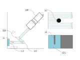
도 1(a)는 본 발명의 미러 및 비전시스템을 이용한 물체의 선단부 위치정렬장치의 실물사진이고, (b)는 개략적인 구성도이고, 도 2는 본 발명의 미러 및 비전시스템을 이용한 물체의 선단부 위치정렬장치의 빛의 경로 및 우측영역에 촬영되는 영상을 나타내는 개략적인 구성도이고, 도 3은 본 발명의 미러 및 비전시스템을 이용한 물체의 선단부 위치정렬장치의 빛의 경로 및 좌측영역에 촬영되는 영상을 나타내는 개략적인 구성도이고, 도 4는 본 발명의 미러 및 비전시스템을 이용한 물체의 선단부 위치정렬장치의 빛의 경로를 나타내는 개략적인 구성도이고, 도 5는 본 발명의 미러 및 비전시스템을 이용한 물체의 선단부 위치정렬장치로 촬영한 영상을 나타내는 사진이며, (a)는 대상물이 기준점에 있는 경우의 x, y, z 좌표이며, (b)는 y좌표가 이동한 경우의 y'좌표이며, (c)는 x좌표가 이동한 경우의 x'좌표이고, 도 6은 상기 도 5의 좌우측 영상의 좌표가 이동하는 것을 광선의 조사방향에 따라 나타낸 도면이며, (a)는 대상물이 기준점에 있는 경우의 x, y, z 좌표이며, (b)는 좌측 영상의 y좌표가 y1 만큼 이동한 경우의 y'좌표이며, (c)는 우측 영상의 x좌표가 x1 만큼 이동한 경우의 x'좌표를 나타내고, 도 7은 상기 도 5의 좌우측 영상의 좌표가 이동하는 것을 광선의 조사방향에 따라 나타낸 도면이며, (a)는 대상물이 정상적인 정렬상태에서 선단부의 높이를 나타내는 경우의 z좌표이며, (b)는 z좌표가 z1 만큼 이동한 (높아진)경우의 z'좌표이다.Figure 1 (a) is a real picture of the position alignment device of the tip of the object using the mirror and vision system of the present invention, (b) is a schematic configuration diagram, Figure 2 is a view of the object using the mirror and vision system of the present invention 3 is a schematic configuration diagram showing an image of the light path and the right area of the tip alignment device, and FIG. 3 is a view of the light path and the left region of the tip alignment device of the object using the mirror and vision system of the present invention. Figure 4 is a schematic configuration diagram showing the image, Figure 4 is a schematic configuration diagram showing the path of the light of the position alignment device of the front end portion of the object using the mirror and vision system of the present invention, Figure 5 is a mirror and vision system of the present invention (A) is the x, y, z coordinate when the object is at the reference point, and (b) is the y coordinate when the object is positioned at the reference point. y 'coordinate, (c) is the x' coordinate when the x coordinate is moved, Figure 6 is a view showing the movement of the coordinates of the left and right images of Figure 5 according to the irradiation direction of the light beam, (a) is X, y, z coordinates when the object is at the reference point, (b) is y 'coordinates when the y coordinate of the left image is moved by y 1 , (c) is x x of the right image by x 1 FIG. 7 is a diagram illustrating the movement of the coordinates of the left and right images of FIG. 5 according to the irradiation direction of the light beam, and (a) shows the height of the tip portion in the normal alignment state of the object. The z coordinate of the case, and (b) is the z 'coordinate of the case where the z coordinate is moved (higher) by z 1 .
또한, 도 8은 본 발명의 미러 및 비전시스템을 이용한 물체의 선단부 위치정렬방법의 각 단계별 공정도이며, 도 9는 본 발명의 미러 및 비전시스템을 이용한 물체의 선단부 위치정렬방법의 물체의 선단부 위치를 찾는 방법을 나타내는 공정도이며, 도 10은 본 발명의 미러 및 비전시스템을 이용한 물체의 선단부 위치정렬방법의 선단부의 편심을 측정하는 방법을 나타내는 공정도이다.8 is a step-by-step process diagram of the method of aligning the distal position of an object using the mirror and vision system of the present invention, and FIG. 9 is a position of the distal end of the object of the distal position alignment method of the object using the mirror and vision system of the present invention. 10 is a process chart showing a finding method, and FIG. 10 is a process chart showing a method of measuring the eccentricity of the front end portion of the front end position alignment method of the object using the mirror and vision system of the present invention.
도 1에서 보는 바와 같이, 이러한 본 발명의 미러 및 비전시스템을 이용한 물체의 선단부 위치정렬장치(10)는, 초경인서트 제품 이송장비(이하, ‘본체장비’라 한다)의 결합되며, 빛을 물체에 조사(照射)하여 얻어지는 영상(影像:12)을 이용하여 작업 공구(이하 ‘대상물’이라 한다) 선단부(先端部:11.1)의 3차원 위치 및 편심 량을 측정하여, 공구의 좌표 보정 및 교체시기를 결정하도록 구성된다.As shown in Figure 1, the front end
상기 본체장비에 결합되는 공구는 사용빈도가 높을수록 선단부의 마모 및 중심축으로부터 편심되어 정밀도가 현저하게 떨어지고 불량제품을 생산하는 등 작업에 지장을 초래한다. 본 발명에 따른 미러 및 비전시스템을 이용한 물체의 선단부 위치정렬장치(10)는 본체장비의 공간부에 장착하여 작업을 시작하기 전에 공구 선단부의 3차원 좌표 및 편심 량을 측정하고, 일정시간 간격으로 다시 측정하여 좌표 및 편심 량을 보상해 줌으로서 본체장비의 정밀도를 보증할 수 있으며, 공구의 교체시기를 예상함으로서 작업효율을 향상시킬 수 있도록 구성된다. 이러한 구성은 본체장비의 엑추에이터(미도시) 및 PLC(미도시)에 의해 구동 및 명령된다. The higher the frequency of use of the tool coupled to the main body equipment is eccentric from the wear of the tip and the central axis, the precision is significantly lowered, and the production of defective products, such as a problem in the operation. The front end
도 1을 계속해서 참조하면, 본 발명의 미러 및 비전시스템을 이용한 물체의 선단부 위치정렬장치(10)는, 라이트(110), 미러(120), 비전(130) 및 바디(10.2)을 포함하여 구성된다.With continued reference to FIG. 1, the distal
이러한 본 발명의 미러 및 비전시스템을 이용한 물체의 선단부 위치정렬장치의 상기 바디(10.2)는, 직사각형의 평면 플레이트로서 바닥면(10.21)에 상기 라이트(110), 미러(120), 비전(130)을 탑재하도록 구성된다.The body 10.2 of the distal position alignment device of the object using the mirror and vision system of the present invention is a rectangular flat plate on the bottom surface 10.21 of the light 110,
이 때, 상기 라이트(110), 미러(120), 비전(130)은 바닥면(10.21)으로부터 동일한 높이를 유지하여 상기 라이트(110)에서 빛이 작업위치(10.1)의 대상물(11)을 조사하여 발생되는 영상(12)이 미러(120)를 통하여 최종적으로 비전(130)에 정확한 x, y, z 좌표를 형성하는 영상을 얻을 수 있도록 수평을 이루어 탑재하도록 구성된다.In this case, the light 110, the
도 4를 참조하면, 이러한 본 발명의 미러 및 비전시스템을 이용한 물체의 선단부 위치정렬장치의 상기 라이트(110)는, 작업위치(10.1)의 대상물(11)을 기준으로 일 측에서 상기 대상물(11)을 향해 수평으로 빛을 조사하도록 구성된다.Referring to FIG. 4, the
이러한 본 발명의 상기 라이트(110)는, 제1 라이트(111)와, 제2 라이트(112)로 이루어지며, 상기 두 개의 라이트(111, 112)는 상기 바디(10.2)에서 상기 대상물(11)을 기준으로 일정한 거리에 90°내각을 이루어 상기 대상물(11)을 수평으로 조사하도록 구성된다.The light 110 of the present invention includes a
이러한 본 발명의 미러 및 비전시스템을 이용한 물체의 선단부 위치정렬장치의 상기 미러(120)는, 상기 대상물(11)을 기준으로 상기 라이트(110)와 대향되는 위치에 상기 라이트(110)에서 조사된 빛에 의해 발생하는 영상(12)을 입사 및 반사하도록 구성된다.The
도 2 및 도 3을 참조하면, 이러한 본 발명의 상기 미러(120)는, 제1 미러(121)와, 제2 미러(122) 및 통합 미러(123)로 이루어지며, 상기 제1 미러(121)는 상기 제1 라이트(111)에서 조사되는 빛에 의해 형성되는 영상(12)을 입/반사하도록 상기 대상물(11)로부터 일정한 거리에 위치하며, 상기 제2 미러(122)는 상기 제2 라이트(112)에서 조사되는 빛에 의해 형성되는 영상(12)을 입/반사하도록 상기 대상물로부터 일정한 거리에 위치하며, 상기 통합 미러(123)는 상기 제1 미러(121)와 제2 미러(122)로부터 입사되는 각 영상(12)을 상기 비전(130)으로 반사하도록 형성된다.2 and 3, the
또한, 도 4에서 보는 바와 같이, 이러한 본 발명의 상기 통합 미러(123)는, 상기 제1 미러(121)와 제2 미러(122)로부터 입사되는 상기 각 영상(12)이 평행을 이루어 상기 비전(130)으로 반사되도록 구성된다.In addition, as shown in FIG. 4, in the
이 때, 상기 통합 미러(123)는 두 개의 거울의 일 측 단부를 맞대어, 맞댄 단부의 내각이 90°가 되도록 하여, 상기 제1 미러(121)와 제2 미러(122)로부터 입사되는 대상물(11)의 영상이 평행을 이루며 비전으로 반사되도록 구성된다.At this time, the
도 5 내지 도 7을 참조하면, 이러한 본 발명의 미러 및 비전시스템을 이용한 물체의 선단부 위치정렬장치의 상기 비전(130)은, 상기 미러(120)에서 반사되는 영상(12)을 촬영하도록 구성된다.5 to 7, the
이러한 본 발명의 상기 비전(130)은, 상기 통합 미러(123)에서 반사되는 영상(12)을 각각 좌측 영역(131) 및 우측 영역(132)에 촬영하도록 구성된다.The
또한, 도 8에 기재한바와 같이, 본 발명은 빛을 물체에 조사(照射)하여 얻어지는 영상(影像:12)을 이용하여 작업 공구 선단부(先端部:11.1)의 3차원 위치 및 편심 량을 측정하여, 공구의 좌표 보정 및 교체시기를 결정하는 미러 및 비전시스템을 이용한 물체의 선단부 위치정렬방법에 관한 것이다.In addition, as shown in Fig. 8, the present invention measures the three-dimensional position and the amount of eccentricity of the work tool tip by using an
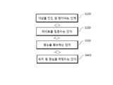
이러한 본 발명의 미러 및 비전시스템을 이용한 물체의 선단부 위치정렬방법은, (a) 대상물(11) 진입 및 정지단계(S100); (b) 라이트(110) 점등단계(S200); (c) 영상(12) 확보단계(S300); (d) 위치 및 편심 측정단계(S400)를 포함하도록 구성된다.Such a method of aligning the distal end portion of an object using the mirror and vision system of the present invention includes: (a) an
이러한 본 발명의 미러 및 비전시스템을 이용한 물체의 선단부 위치정렬방법의 상기 (a) 대상물(11) 진입 및 정지단계(S100)는, 대상물(11)의 선단부(11.1)를 작업위치(10.1)에 진입하여 바닥면(10.21)으로부터 일정 높이에 정지하도록 구성된다.In the (a)
이러한 본 발명의 미러 및 비전시스템을 이용한 물체의 선단부 위치정렬방법은, 상기 (b) 라이트(110) 점등단계(S200)는, (ba) 제1 라이트(111)를 점등하여 대상물을 조사하는 단계(S210)와, (bb) 제2 라이트(112)를 점등하여 대상물을 조사하는 단계(S220)를 더 포함하여 구성된다.In the method of aligning the distal end portion of an object using the mirror and vision system of the present invention, the (b) light 110 lighting step (S200), (ba) lighting the
이러한 본 발명의 미러 및 비전시스템을 이용한 물체의 선단부 위치정렬방법의 상기 (c) 영상(12) 확보단계(S300)는, (ca) 상기 제1 라이트(111)를 켜서 얻는 우측 영상(12.2)은 비전(130)의 우측 영역(132)에 촬영하여 확보하는 단계(S310)와, (cb) 상기 제2 라이트(112)를 켜서 얻는 좌측 영상(12.1)은 비전(130)의 좌측 영역(131)에 촬영하여 확보하는 단계(S320)를 더 포함하여 구성된다.The (c)
이러한 본 발명의 미러 및 비전시스템을 이용한 물체의 선단부 위치정렬방법의 상기 (d) 위치 및 편심 측정단계(S400)는, (da) 3차원 위치를 측정하는 단계(S410)와, (db) 회전체의 편심 량을 측정하는 단계(S420)를 더 포함하여 구성된다.The (d) position and eccentricity measuring step (S400) of the tip position alignment method of the object using the mirror and vision system of the present invention, (da) measuring the three-dimensional position (S410) and (db) times It further comprises a step (S420) of measuring the total amount of eccentricity.
이러한 본 발명의 상기 (da) 3차원 위치를 측정하는 단계(S410)는, 비전(130)의 우측 영역(12.2)에 맺힌 상(像)의 결과로 선단의 x좌표를 측정하고, 좌측 영역(12.1)에 맺힌 상(像)의 결과로 선단의 y좌표를 측정하고, 비전의 중앙 높이로부터 상의 높이를 선단의 z좌표를 측정하도록 구성된다.In the step (da) of measuring the three-dimensional position (da) of the present invention, the x-coordinate of the tip is measured as a result of the image formed in the right region 12.2 of the
이러한 본 발명의 상기 (db) 회전체의 편심 량을 측정하는 단계(S420)는, 상기 대상물의 선단부(11.1)를 회전하며 상기 (da) 단계(S410)를 2회 이상 반복, 동심원의 경로를 계산하여 편심 량을 측정하도록 구성된다.In the step (S420) of measuring the amount of eccentricity of the (db) rotor of the present invention, the front end portion (11.1) of the object is rotated and the (da) step (S410) repeated two or more times, the path of the concentric circles It is configured to calculate the amount of eccentricity by calculating.
본 발명에 따른 미러 및 비전시스템을 이용하여 대상물 선단부의 3차원 좌표를 측정하는 방법 및 대상물을 회전시켜 편심 량을 측정하는 방법의 실시 예를 설명하면 아래와 같다.Referring to the embodiment of the method for measuring the three-dimensional coordinates of the front end of the object using a mirror and vision system according to the present invention and a method for measuring the amount of eccentricity by rotating the object as follows.
<실시 예 1> 대상물이 기준점에 있는 경우의 3차원 좌표(x, y, z)를 측정하는 방법[도 5(a), 도 6(a), 도 7(a), 도 9 참조] Example 1 A method of measuring three-dimensional coordinates (x, y, z) when an object is at a reference point (see FIGS. 5 (a), 6 (a), 7 (a) and 9)]
1. 대상물(11)을 작업위치(10.1)에 진입시켜 선단부(11.1)를 일정 높이에서 정지한다.1. The
2. 제1 라이트를 켜서 대상물(11)의 영상(12)을 촬영하여 우측 영역(132)에 우측 영상(12.2)을 확보한다.2. The first light is turned on to capture the
3. 제2 라이트를 켜서 대상물(11)의 영상(12)을 촬영하여 좌측 영역(131)에 좌측 영상(12.1)을 확보한다.3. The second light is turned on to capture the
4. 3차원 좌표(x, y, z)를 측정한다.4. Measure three-dimensional coordinates (x, y, z).
- 상기 우측 영역(12.2)에 맺힌 상(像)의 결과로 선단의 x좌표를 측정, 좌측 영역(12.1)에 맺힌 상(像)의 결과로 선단의 y좌표를 측정, 비전 화상의 중앙높이를 선단의 z좌표를 측정. The x-coordinate of the tip is measured as a result of the image formed in the right region 12.2, and the y-coordinate of the tip is measured as a result of the image formed in the left region 12.1 to determine the center height of the vision image. Measure the z-coordinate of the tip.
<실시 예 2> 대상물이 이동한 경우의 3차원 좌표(x', y', z')를 측정하는 방법[도 5(b, c), 도 6(b, c), 도 7(b), 도 9 참조] <Example 2> A method of measuring three-dimensional coordinates (x ', y', z ') when the object is moved [Fig. 5 (b, c), Fig. 6 (b, c), Fig. 7 (b) , See FIG. 9]
1. 이동한 대상물(11)을 작업위치(10.1)에 진입시켜 선단부(11.1)를 일정 높이에서 정지한다.1. The moved
2. 제1 라이트를 켜서 이동한 대상물(11)의 영상(12)을 촬영하여 우측 영역(132)에 우측 영상(12.2)을 확보한다.2. The
3. 제2 라이트를 켜서 이동한 대상물(11)의 영상(12)을 촬영하여 좌측 영역(131)에 좌측 영상(12.1)을 확보한다.3. The
4. 이동한 대상물의 3차원 좌표(x', y', z')를 측정한다.4. Measure the three-dimensional coordinates (x ', y', z ') of the moved object.
- 상기 우측 영역(12.2)에 맺힌 상(像)의 결과로 선단의 x'좌표를 측정, 좌측 영역(12.1)에 맺힌 상(像)의 결과로 선단의 y'좌표를 측정, 비전의 중앙 높이로부터 상의 높이를 선단의 z'좌표를 측정. The x 'coordinate of the tip is measured as a result of the image formed in the right region 12.2, and the y' coordinate of the tip is measured as a result of the image formed in the left region 12.1, the center height of the vision Measure the height of the top from the z 'coordinate.
5. 이동한 대상물에 3차원 좌표(x', y', z')의 이동 값(x1, y1, z1)을 보정한다.5. Correct the moving values (x 1 , y 1 , z 1) of the three-dimensional coordinates (x ', y', z ') on the moved object.
<실시 예 3> 대상물의 편심 량을 측정하는 방법[도 9 및 도 10 참조] Example 3 A method of measuring the amount of eccentricity of an object [see FIGS. 9 and 10]
1. 대상물(11)을 작업위치(10.1)에 진입시켜 선단부(11.1)를 일정 높이에서 정지한다.1. The
2. 제1 라이트를 켜서 대상물(11)의 영상(12)을 촬영하여 우측 영역(132)에 우측 영상(12.2)을 확보한다.2. The first light is turned on to capture the
3. 제2 라이트를 켜서 대상물(11)의 영상(12)을 촬영하여 좌측 영역(131)에 좌측 영상(12.1)을 확보한다.3. The second light is turned on to capture the
4. 3차원 좌표(x, y, z)를 측정한다.4. Measure three-dimensional coordinates (x, y, z).
- 상기 우측 영역(12.2)에 맺힌 상(像)의 결과로 선단의 x좌표를 측정, 좌측 영역(12.1)에 맺힌 상(像)의 결과로 선단의 y좌표를 측정, 비전의 중앙 높이로부터 상의 높이를 선단의 z좌표를 측정. Measuring the x-coordinate of the tip as a result of the image formed in the right region 12.2 and measuring the y-coordinate of the tip as a result of the image formed in the left region 12.1, Measure the z coordinate of the tip.
5. 대상물의 선단부를 임의의 각도(θ)로 회전한다.5. Rotate the tip of the object at any angle (θ).
6. 제1 라이트를 켜서 대상물(11)의 영상(12)을 촬영하여 우측 영역(132)에 우측 영상(12.2)을 확보한다.6. The first light is turned on to capture the
7. 제2 라이트를 켜서 대상물(11)의 영상(12)을 촬영하여 좌측 영역(131)에 좌측 영상(12.1)을 확보한다.7. The second light is turned on to capture the
8. 3차원 좌표(xθ, yθ, zθ)를 측정한다.8. Measure the three-dimensional coordinates (x θ , y θ , z θ ).
9.상기 3차원 좌표 값[(x, y, z), (xθ, yθ, zθ)]으로 편심 량(x-1, y-1, z-1)을 산출한다.9. The eccentric amount (x -1 , y -1 , z -1 ) is calculated from the three-dimensional coordinate values [(x, y, z), (x θ , y θ , z θ )].
10. 계속해서 상기 5. 대상물의 선단부를 회전시키면서, 6→7→8→9 순으로 실시하여 동심원의 경로를 파악하여 편심 량을 측정한다.10. Subsequently, while rotating the tip of the object, measure 6 ~ 7 → 8 → 9 to determine the path of concentric circles and measure the amount of eccentricity.
이와 같은 본 발명의 미러 및 비전시스템을 이용한 물체의 선단부 위치정렬장치 및 그 방법은 다음과 같은 특징을 가진다.The tip position alignment device and method of the object using the mirror and vision system of the present invention has the following features.
먼저, 본 발명의 미러 및 비전시스템을 이용한 물체의 선단부 위치정렬장치는 라이트(110), 미러(120), 비전(130)으로 구성되어 있다.First, the position alignment device of the tip of the object using the mirror and vision system of the present invention is composed of a light 110, a
따라서 본 발명은 간단한 구성으로 공구의 3차원 좌표 및 편심 량을 측정하여 보정함으로서 본체장비의 정밀도를 향상하고 공구의 교체시기를 예상함으로서 작업효율을 향상시키는 장점을 가지고 있다. Therefore, the present invention has the advantage of improving the work efficiency by measuring the three-dimensional coordinates and the amount of eccentricity of the tool with a simple configuration to improve the accuracy of the main body equipment and to predict the replacement time of the tool.
또한, 본 발명의 미러 및 비전시스템을 이용한 물체의 선단부 위치정렬장치의 작업위치(10.1)는 작은 공간으로 형성되어 정지상태에서 좌표를 측정할 수 있다. In addition, the working position 10.1 of the tip position alignment device of the object using the mirror and vision system of the present invention is formed in a small space to measure the coordinates in the stationary state.
따라서 장치를 콤팩트하게 만들 수 있어 본체장비에 결합하는데 어려움이 없는 장점을 가지고 있다.Therefore, the device can be made compact, which has the advantage that there is no difficulty in coupling to the main body equipment.
또한, 본 발명의 미러 및 비전시스템을 이용한 물체의 선단부 위치정렬장치는 한 대의 비전과 미러를 사용하는 소형구조이다.In addition, the distal position alignment device of the object using the mirror and vision system of the present invention is a compact structure using a single vision and mirror.
일반적으로 3차원 좌표를 측정하기 위해서는 각각의 측정 센서를 필요로 하나, 본 발명은 영상 촬영기법을 이용함으로서 장치가 콤팩트해지고, 일반적인 비전 방식인 패턴 비교 방식에 비해 정확하고 정량적인 표현이 가능한 장점이 있다.In general, each measurement sensor is required to measure three-dimensional coordinates, but the present invention provides an advantage that the device is compact by using an imaging technique, and that an accurate and quantitative expression can be expressed compared to a pattern comparison method, which is a general vision method. have.
10 : 미러 및 비전시스템을 이용한 물체의 선단부 위치정렬장치
10.1 : 작업위치(Working zone)
10.2 : 바디
10.21 :바닥면
11 : 대상물
11.1 : 선단부(先端部)
12 : 영상(影像)
12.1 : 좌측 영상
12.2 : 우측 영상
110 : 라이트
111 : 제1 라이트
112 : 제2 라이트
120 : 미러
121 : 제1 미러
122 : 제2 미러
123 : 통합 미러
130 : 비전
131 : 좌측 영역
132 : 우측 영역10: Positioning device of tip of object using mirror and vision system
10.1: Working zone
10.2: Body
10.21: bottom
11: object
11.1: tip
12: video
12.1: Left image
12.2: Right image
110: light
111: first light
112: second light
120 mirror
121: the first mirror
122: second mirror
123: integrated mirror
130: vision
131: left region
132: right area
Claims (11)
작업위치(10.1)의 대상물(11)을 기준으로 일 측에서 상기 대상물을 향해 수평으로 빛을 조사하도록 구성되는 라이트(110);
상기 대상물을 기준으로 상기 라이트와 대향되는 위치에 상기 라이트에서 조사된 빛에 의해 발생하는 영상(12)을 입/반사하도록 구성되는 미러(120);
상기 미러에서 반사되는 영상(12)을 촬영하도록 구성되는 비전(130);을 포함하는 것을 특징으로 하는 미러 및 비전시스템을 이용한 물체의 선단부 위치정렬장치.
The coordinates of the tool are measured by measuring the three-dimensional position and the amount of eccentricity of the tip of the work tool (hereinafter referred to as 'object') using an image obtained by irradiating light onto an object. The present invention relates to a device for aligning the distal end portion of an object using a mirror and vision system that determines the timing of correction and replacement.
A light 110 configured to irradiate light horizontally toward the object from one side with respect to the object 11 at the work position 10.1;
A mirror (120) configured to input / reflect an image (12) generated by light emitted from the light at a position opposite to the light with respect to the object;
And a vision (130) configured to capture an image (12) reflected from the mirror.
상기 라이트(110)는, 상기 대상물(11)을 기준으로 일정한 거리에 90°내각을 이루어 상기 대상물을 수평으로 조사하도록 구성되는 제1 라이트(111)와, 제2 라이트(112)로 이루어지는 것을 특징으로 하는 미러 및 비전시스템을 이용한 물체의 선단부 위치정렬장치.
The method according to claim 1,
The light 110 may include a first light 111 and a second light 112 configured to irradiate the object horizontally by forming a 90 ° cabinet at a predetermined distance with respect to the object 11. Positioning device of the tip of an object using a mirror and vision system.
상기 미러(120)는,
상기 제1 라이트(111)에서 조사되는 빛에 의해 형성되는 영상(12)을 입/반사하도록 상기 대상물(11)로부터 일정한 거리에 위치하는 제1 미러(121)와,
상기 제2 라이트(112)에서 조사되는 빛에 의해 형성되는 영상(12)을 입/반사하도록 상기 대상물로부터 일정한 거리에 위치하는 제2 미러(122)와,
상기 제1 미러(121)와 제2 미러(122)로부터 입사되는 각 영상(12)을 상기 비전(130)으로 반사하도록 형성되는 통합 미러(123)로 이루어지는 것을 특징으로 하는 미러 및 비전시스템을 이용한 물체의 선단부 위치정렬장치.
The method according to claim 2,
The mirror 120 is,
A first mirror 121 positioned at a predetermined distance from the object 11 to receive / reflect the image 12 formed by the light emitted from the first light 111;
A second mirror 122 positioned at a predetermined distance from the object to receive / reflect the image 12 formed by the light emitted from the second light 112;
Using a mirror and a vision system, characterized in that the integrated mirror 123 is formed to reflect each image 12 incident from the first mirror 121 and the second mirror 122 to the vision 130 Positioning device of the tip of the object.
상기 통합 미러(123)는, 제1 미러(121)와 제2 미러(122)로부터 입사되는 상기 각 영상(12)이 평행을 이루어 상기 비전(130)으로 반사되도록, 두 개의 거울의 일 측 단부를 맞대어 형성되는 것을 특징으로 하는 미러 및 비전시스템을 이용한 물체의 선단부 위치정렬장치.
The method according to claim 3,
The integrated mirror 123 has one end portion of two mirrors such that the respective images 12 incident from the first mirror 121 and the second mirror 122 are reflected in parallel to the vision 130. Positioning device of the front end portion of the object using a mirror and a vision system, characterized in that formed against.
상기 비전(130)은, 상기 통합 미러(123)에서 반사되는 영상(12)을 각각 좌측 영역(131) 및 우측 영역(132)에 촬영하도록 구성하는 것을 특징으로 하는 미러 및 비전시스템을 이용한 물체의 선단부 위치정렬장치.
The method according to claim 4,
The vision 130 is configured to capture the image 12 reflected by the integrated mirror 123 in the left region 131 and the right region 132, respectively, of the object using the mirror and vision system Tip position alignment device.
(a) 대상물(11)이 작업위치(10.1)에 진입하여 바닥면(10.21)으로부터 일정 높이에 정지하는 단계(S100);
(b) 라이트(110)를 점등하는 단계(S200);
(c) 영상(12)을 촬영하여 확보하는 단계(S300);
(d) 3차원 위치 및 편심 량을 측정하는 단계(S400);를 포함하는 것을 특징으로 하는 미러 및 비전시스템을 이용한 물체의 선단부 위치정렬방법.
A mirror that determines the coordinate correction and replacement time of the tool by measuring the three-dimensional position and the amount of eccentricity of the tip of the work tool by using an image obtained by irradiating light onto an object. And a vision position alignment method of an object using a vision system,
(A) step of the object 11 enters the working position (10.1) and stops at a predetermined height from the bottom surface (10.21) (S100);
(b) turning on the light 110 (S200);
(c) photographing and securing an image 12 (S300);
(D) measuring the three-dimensional position and the amount of eccentricity (S400); characterized in that it comprises a front end position alignment method of the object using a mirror and vision system.
상기 (b) 라이트 점등 단계는,
(ba) 제1 라이트(111)를 점등하여 대상물을 조사하는 단계(S210)와,
(bb) 제2 라이트(112)를 점등하여 대상물을 조사하는 단계(S220)를 더 포함하는 것을 특징으로 하는 미러 및 비전시스템을 이용한 물체의 선단부 위치정렬방법.
The method according to claim 6,
The (b) light lighting step,
(ba) lighting the object by lighting the first light 111 (S210);
(bb) illuminating the object by lighting the second light (112) (S220) further comprising the position alignment method of the front end of the object using a mirror and vision system.
상기 (c) 영상 확보 단계(S300)는, (ca) 상기 제1 라이트(111)를 켜서 얻는 우측 영상(12.2)은 비전(130)의 우측 영역(132)에 촬영하여 확보하는 단계(S310), (cb) 상기 제2 라이트(112)를 켜서 얻는 좌측 영상(12.1)은 비전(130)의 좌측 영역(131)에 촬영하여 확보하는 단계(S320)를 더 포함하는 것을 특징으로 하는 미러 및 비전시스템을 이용한 물체의 선단부 위치정렬방법.
The method according to claim 7,
The (c) image securing step (S300), (ca) obtaining a right image (12.2) obtained by turning on the first light (111) to the right area 132 of the vision 130 to secure (S310) , (cb) the left image 12.1 obtained by turning on the second light 112 further comprises the step (S320) of capturing and securing to the left area 131 of the vision 130 (S320) A method of aligning the tip of an object using a system.
상기 (d) 측정 단계(S400)는,
(da) 3차원 위치를 측정하는 단계(S410)와,
(db) 회전체의 편심 량을 측정하는 단계(S420)를 더 포함하는 것을 특징으로 하는 미러 및 비전시스템을 이용한 물체의 선단부 위치정렬방법.
The method according to claim 8,
The (d) measuring step (S400),
(da) measuring a three-dimensional position (S410),
(db) Method for aligning the distal end portion of the object using a mirror and vision system, characterized in that it further comprises the step of measuring the amount of eccentricity of the rotating body (S420).
상기 (da) 3차원 위치를 측정하는 단계(S410)는, 비전(130)의 우측 영역(12.2)에 맺힌 상(像)의 결과로 선단의 x좌표를 측정하고, 좌측 영역(12.1)에 맺힌 상(像)의 결과로 선단의 y좌표를 측정하고, 비전의 중앙 높이로부터 상의 높이를 선단의 z좌표를 측정하는 것을 특징으로 하는 미러 및 비전시스템을 이용한 물체의 선단부 위치정렬방법.
The method according to claim 9,
In the step (da) of measuring (D) the three-dimensional position (S410), the x-coordinate of the tip is measured as a result of the image formed in the right region 12.2 of the vision 130, and is formed in the left region 12.1. And measuring the y-coordinate of the tip as a result of the image, and measuring the z-coordinate of the tip from the height of the vision to the height of the image.
상기 (db) 회전체의 편심 량을 측정하는 단계(S420)는, 상기 대상물의 선단부(11.1)를 회전하며 상기 (da) 단계(S410)를 2회 이상 반복, 동심원의 경로를 계산하여 편심 량을 측정하는 것을 특징으로 하는 미러 및 비전시스템을 이용한 물체의 선단부 위치정렬방법.
The method according to claim 10,
In step (S420) of measuring the amount of eccentricity of the rotating body, the front end portion (11.1) of the object is rotated and the (D) step (S410) is repeated two or more times, the amount of eccentricity is calculated by calculating a path of concentric circles. Method for aligning the distal end of the object using a mirror and vision system, characterized in that for measuring.
Priority Applications (1)
| Application Number | Priority Date | Filing Date | Title |
|---|---|---|---|
| KR1020180072813A KR102087037B1 (en) | 2018-06-25 | 2018-06-25 | Apparatus and method for aligning the tip of an object using mirrors and vision system |
Applications Claiming Priority (1)
| Application Number | Priority Date | Filing Date | Title |
|---|---|---|---|
| KR1020180072813A KR102087037B1 (en) | 2018-06-25 | 2018-06-25 | Apparatus and method for aligning the tip of an object using mirrors and vision system |
Publications (2)
| Publication Number | Publication Date |
|---|---|
| KR20200000689A true KR20200000689A (en) | 2020-01-03 |
| KR102087037B1 KR102087037B1 (en) | 2020-03-10 |
Family
ID=69155692
Family Applications (1)
| Application Number | Title | Priority Date | Filing Date |
|---|---|---|---|
| KR1020180072813A KR102087037B1 (en) | 2018-06-25 | 2018-06-25 | Apparatus and method for aligning the tip of an object using mirrors and vision system |
Country Status (1)
| Country | Link |
|---|---|
| KR (1) | KR102087037B1 (en) |
Cited By (1)
| Publication number | Priority date | Publication date | Assignee | Title |
|---|---|---|---|---|
| CN114714153A (en) * | 2022-04-22 | 2022-07-08 | 成都飞机工业(集团)有限责任公司 | Auxiliary fixture and detection method for detecting vertical C-axis positioning accuracy of eccentric structure |
Citations (7)
| Publication number | Priority date | Publication date | Assignee | Title |
|---|---|---|---|---|
| KR100399471B1 (en) * | 1999-12-28 | 2003-09-29 | 가부시키가이샤 신가와 | Bonding apparatus and bonding method |
| KR100413103B1 (en) * | 2000-01-21 | 2003-12-31 | 가부시키가이샤 신가와 | Bonding apparatus and bonding method |
| JP2010278128A (en) * | 2009-05-27 | 2010-12-09 | Shinkawa Ltd | Bonding device, and method of correcting offset amount of bonding device |
| KR101061941B1 (en) | 2008-12-11 | 2011-09-05 | 웰텍코리아 (주) | Method for manufacturing tool bonded cubic boron nitride (CB) and cubic boron nitride (CB) tool using the same |
| KR101172925B1 (en) | 2005-10-04 | 2012-08-10 | 스미또모 덴꼬오 하드메탈 가부시끼가이샤 | cBN SINTERED BODY FOR HIGH SURFACE INTEGRITY MACHINING AND cBN SINTERED BODY CUTTING TOOL |
| JP5236223B2 (en) * | 2007-07-25 | 2013-07-17 | キヤノンマシナリー株式会社 | Die bonder and die bonding method |
| JP2015182159A (en) * | 2014-03-24 | 2015-10-22 | 三菱重工業株式会社 | Measuring apparatus for tool displacement of machine tool |
-
2018
- 2018-06-25 KR KR1020180072813A patent/KR102087037B1/en active IP Right Grant
Patent Citations (7)
| Publication number | Priority date | Publication date | Assignee | Title |
|---|---|---|---|---|
| KR100399471B1 (en) * | 1999-12-28 | 2003-09-29 | 가부시키가이샤 신가와 | Bonding apparatus and bonding method |
| KR100413103B1 (en) * | 2000-01-21 | 2003-12-31 | 가부시키가이샤 신가와 | Bonding apparatus and bonding method |
| KR101172925B1 (en) | 2005-10-04 | 2012-08-10 | 스미또모 덴꼬오 하드메탈 가부시끼가이샤 | cBN SINTERED BODY FOR HIGH SURFACE INTEGRITY MACHINING AND cBN SINTERED BODY CUTTING TOOL |
| JP5236223B2 (en) * | 2007-07-25 | 2013-07-17 | キヤノンマシナリー株式会社 | Die bonder and die bonding method |
| KR101061941B1 (en) | 2008-12-11 | 2011-09-05 | 웰텍코리아 (주) | Method for manufacturing tool bonded cubic boron nitride (CB) and cubic boron nitride (CB) tool using the same |
| JP2010278128A (en) * | 2009-05-27 | 2010-12-09 | Shinkawa Ltd | Bonding device, and method of correcting offset amount of bonding device |
| JP2015182159A (en) * | 2014-03-24 | 2015-10-22 | 三菱重工業株式会社 | Measuring apparatus for tool displacement of machine tool |
Cited By (1)
| Publication number | Priority date | Publication date | Assignee | Title |
|---|---|---|---|---|
| CN114714153A (en) * | 2022-04-22 | 2022-07-08 | 成都飞机工业(集团)有限责任公司 | Auxiliary fixture and detection method for detecting vertical C-axis positioning accuracy of eccentric structure |
Also Published As
| Publication number | Publication date |
|---|---|
| KR102087037B1 (en) | 2020-03-10 |
Similar Documents
| Publication | Publication Date | Title |
|---|---|---|
| CN110605388B (en) | System for additive manufacturing and measurement method of additive manufacturing process | |
| CN111702173B (en) | Molding apparatus and molding method | |
| CN111151750B (en) | Molding device and molding method | |
| CN108080634B (en) | Laminated molding device | |
| CN102814872B (en) | Processing unit (plant) | |
| CN110248765B (en) | Method for machining cutting inserts and corresponding device for machining cutting inserts | |
| CN206029021U (en) | A device that is used for surperficial copper -plated liquid crystal display panel of radium carving | |
| JP2022533695A (en) | MACHINING MODULE AND MACHINE TOOL INCLUDING TOOL OUTER DETECTION UNIT AND TOOL OUTER DETECTION METHOD | |
| CN110093601B (en) | Method and device for laser cladding real-time thickness measurement and feedback | |
| CN108127206B (en) | Laser brazing process transplanting method and laser brazing device capable of transplanting data | |
| JP3587208B1 (en) | Stereolithography processing reference correction method and stereolithography device | |
| KR101492339B1 (en) | Method for controlling laser cladding and laser cladding system | |
| CN111867754A (en) | Method for aligning a multi-beam illumination system | |
| KR102087037B1 (en) | Apparatus and method for aligning the tip of an object using mirrors and vision system | |
| KR20030039929A (en) | Real-time Monitoring and Controlling Method of a Height of Deposit in Laser Cladding and Laser-aided Direct Metal Manufacturing by using Image Photographing and Image Processing and System thereof | |
| KR101673062B1 (en) | Method for measuring height of melt pool generated in laser cladding | |
| CN102305588A (en) | Dual-laser combined image measurement system | |
| CN111398271A (en) | Detection optimization system and method for laser near-net-shape defect | |
| JP6064871B2 (en) | Thickness measurement method | |
| CN111032253B (en) | Method for additive manufacturing of tip structures on pre-existing parts | |
| JP2000131032A (en) | Method and device for measuring three-dimensional profile | |
| KR102148167B1 (en) | Carbide insert using an orthogonal robot MGT of the high speed inspection equipment and carbide insert top inspection camera milling depth control device for milling | |
| TW201930820A (en) | Three-dimensional target with a dual structure, optical measuring device and method with such a target | |
| CN110456423B (en) | Cutting chip identification for bending units | |
| US11933597B2 (en) | System and method for optical object coordinate determination |
Legal Events
| Date | Code | Title | Description |
|---|---|---|---|
| A201 | Request for examination | ||
| E902 | Notification of reason for refusal | ||
| E701 | Decision to grant or registration of patent right | ||
| GRNT | Written decision to grant |