KR20190113947A - Device for joining two tubes in pre-assembly - Google Patents
Device for joining two tubes in pre-assembly Download PDFInfo
- Publication number
- KR20190113947A KR20190113947A KR1020197026389A KR20197026389A KR20190113947A KR 20190113947 A KR20190113947 A KR 20190113947A KR 1020197026389 A KR1020197026389 A KR 1020197026389A KR 20197026389 A KR20197026389 A KR 20197026389A KR 20190113947 A KR20190113947 A KR 20190113947A
- Authority
- KR
- South Korea
- Prior art keywords
- tube
- retaining
- sleeve
- sealing sleeve
- sealing
- Prior art date
Links
Images


Classifications
-
- F—MECHANICAL ENGINEERING; LIGHTING; HEATING; WEAPONS; BLASTING
- F16—ENGINEERING ELEMENTS AND UNITS; GENERAL MEASURES FOR PRODUCING AND MAINTAINING EFFECTIVE FUNCTIONING OF MACHINES OR INSTALLATIONS; THERMAL INSULATION IN GENERAL
- F16L—PIPES; JOINTS OR FITTINGS FOR PIPES; SUPPORTS FOR PIPES, CABLES OR PROTECTIVE TUBING; MEANS FOR THERMAL INSULATION IN GENERAL
- F16L21/00—Joints with sleeve or socket
- F16L21/002—Sleeves or nipples for pipes of the same diameter; Reduction pieces
- F16L21/005—Sleeves or nipples for pipes of the same diameter; Reduction pieces made of elastic material, e.g. partly or completely surrounded by clamping devices
-
- F—MECHANICAL ENGINEERING; LIGHTING; HEATING; WEAPONS; BLASTING
- F16—ENGINEERING ELEMENTS AND UNITS; GENERAL MEASURES FOR PRODUCING AND MAINTAINING EFFECTIVE FUNCTIONING OF MACHINES OR INSTALLATIONS; THERMAL INSULATION IN GENERAL
- F16L—PIPES; JOINTS OR FITTINGS FOR PIPES; SUPPORTS FOR PIPES, CABLES OR PROTECTIVE TUBING; MEANS FOR THERMAL INSULATION IN GENERAL
- F16L21/00—Joints with sleeve or socket
- F16L21/002—Sleeves or nipples for pipes of the same diameter; Reduction pieces
-
- F—MECHANICAL ENGINEERING; LIGHTING; HEATING; WEAPONS; BLASTING
- F16—ENGINEERING ELEMENTS AND UNITS; GENERAL MEASURES FOR PRODUCING AND MAINTAINING EFFECTIVE FUNCTIONING OF MACHINES OR INSTALLATIONS; THERMAL INSULATION IN GENERAL
- F16L—PIPES; JOINTS OR FITTINGS FOR PIPES; SUPPORTS FOR PIPES, CABLES OR PROTECTIVE TUBING; MEANS FOR THERMAL INSULATION IN GENERAL
- F16L21/00—Joints with sleeve or socket
- F16L21/06—Joints with sleeve or socket with a divided sleeve or ring clamping around the pipe-ends
- F16L21/065—Joints with sleeve or socket with a divided sleeve or ring clamping around the pipe-ends tightened by tangentially-arranged threaded pins
-
- F—MECHANICAL ENGINEERING; LIGHTING; HEATING; WEAPONS; BLASTING
- F16—ENGINEERING ELEMENTS AND UNITS; GENERAL MEASURES FOR PRODUCING AND MAINTAINING EFFECTIVE FUNCTIONING OF MACHINES OR INSTALLATIONS; THERMAL INSULATION IN GENERAL
- F16L—PIPES; JOINTS OR FITTINGS FOR PIPES; SUPPORTS FOR PIPES, CABLES OR PROTECTIVE TUBING; MEANS FOR THERMAL INSULATION IN GENERAL
- F16L21/00—Joints with sleeve or socket
- F16L21/08—Joints with sleeve or socket with additional locking means
Abstract
장치는, 2개의 튜브(1, 2)의 대향 단부 주위에 배치되도록 구성되는 밀봉 슬리브(20)와, 이 밀봉 슬리브가 내부에서 연장되는 클램핑 슬리브(10)를 포함한다. 밀봉 슬리브(20) 및 클램핑 슬리브(10)에 의해 구성되는 요소들 중 하나는, 튜브들 중 하나의 유지표면(1'A, 2'A)과 상호작용하여 클램핑 슬리브 내에서 축선방향 유지하도록 구성되는 적어도 하나의 유지부재(32A, 32B)를 가지며, 상기 유지표면은 클램핑 슬리브에 의해 덮인다.The apparatus comprises a sealing sleeve 20 which is configured to be arranged around opposite ends of the two tubes 1, 2 and a clamping sleeve 10 which extends therein. One of the elements constituted by the sealing sleeve 20 and the clamping sleeve 10 is configured to interact with the retaining surfaces 1'A, 2'A of one of the tubes to remain axially within the clamping sleeve. At least one retaining member 32A, 32B, said retaining surface being covered by a clamping sleeve.

Description
본 발명은, 실질적으로 동일한 직경을 갖는 2개의 정렬된 튜브를 밀봉 방식으로 함께 결합시키기 위한 커플링 장치에 관한 것으로서, 이 장치는 2개의 튜브의 대향 단부 주위에 배치되도록 구성되는 밀봉 슬리브 및 이 밀봉 슬리브가 내부에서 연장되는 클램핑 슬리브를 포함한다.The present invention relates to a coupling device for joining together two aligned tubes having substantially the same diameter in a sealed manner, the device comprising a sealing sleeve and a sealing sleeve configured to be disposed around opposite ends of the two tubes. The sleeve includes a clamping sleeve extending therein.
이러한 유형의 장치는, 예를 들어, 국제특허출원공개 WO 00/75548 및 WO 2006/109002로부터 공지되어 있다.Devices of this type are known, for example, from international patent applications WO 00/75548 and WO 2006/109002.
이 공지의 장치는 클램핑 및 밀봉 측면에서 만족스럽다. 그러나, 실용성의 관점에서, 적어도 하나의 튜브에 이 장치를 사전-장착하여 조립을 용이하게 하고 조임을 시작하기 전에 튜브에 대한 장치의 정확한 위치 설정을 보장하는 것이 유리할 수 있다.This known device is satisfactory in terms of clamping and sealing. In view of practicality, however, it may be advantageous to pre-mount the device on at least one tube to facilitate assembly and to ensure accurate positioning of the device relative to the tube before starting to tighten.
미국특허 US 7,458,619에는, 튜브들 중 하나가 돌출 버튼을 갖는 한편, 클램핑 슬리브는 조임이 수행되기 전에 튜브의 버튼이 맞물리도록 하는 구멍을 구비한 탭을 갖는, 이러한 사전-장착을 가능하게 하는 해결책이 제안되어 있다.U.S. Pat.No. 7,458,619 discloses a solution to enable this pre-mounting, in which one of the tubes has a protruding button, while the clamping sleeve has a tab with a hole that allows the button of the tube to engage before the tightening is performed. It is proposed.
이 시스템은 2개의 외부 요소, 즉 튜브의 버튼과 클램핑 슬리브의 탭을 추가할 것이 요구된다는 단점이 있다. 첫째로, 이러한 요소를 갖는 부품에 이러한 요소를 올바르게 고정시킬 필요가 있다. 둘째로, 이들 요소가 모두 외부로부터 접근 가능한 한, 충격에 직접 노출되기 때문에 이들 요소를 갖는 부품으로부터 분리될 위험이 항상 존재한다. 특히, 구멍을 구비한 탭은 클램핑 슬리브로부터 이동되거나 분리될 수 있다.This system has the disadvantage that it is required to add two external elements, a button of the tube and a tab of the clamping sleeve. Firstly, it is necessary to fix these elements correctly in parts having these elements. Secondly, there is always a risk that these elements will be separated from the component with these elements, as long as they are all accessible from the outside, since they are directly exposed to impact. In particular, the tabs with holes can be moved or separated from the clamping sleeve.
본 개시의 목적은 이러한 기술을 개선하고 전술한 단점의 전부 또는 일부를 극복할 수 있는 장치를 제공하고자 하는 것이다.It is an object of the present disclosure to provide an apparatus that can improve these techniques and overcome all or part of the above mentioned disadvantages.
따라서, 본 개시는, 밀봉 방식으로 2개의 정렬된 튜브를 함께 결합하기 위한 결합 장치로서, 상기 결합 장치는, 2개의 튜브의 대향 단부 주위에 배치되도록 구성되는 밀봉 슬리브와, 상기 밀봉 슬리브가 내부에서 연장되는 클램핑 슬리브를 포함하며; 밀봉 슬리브 및 클램핑 슬리브에 의해 구성되는 요소들 중 하나는, 튜브들 중 하나의 유지표면과 상호작용하여 클램핑 슬리브 내에서 축선방향 유지하도록 구성되는 적어도 하나의 유지부재를 가지며, 상기 유지표면은 클램핑 슬리브에 의해 덮이는 결합 장치를 제공한다.Accordingly, the present disclosure provides a joining device for joining two aligned tubes together in a sealed manner, the joining device comprising a sealing sleeve configured to be disposed around opposite ends of the two tubes, and the sealing sleeve being therein. An elongated clamping sleeve; One of the elements constituted by the sealing sleeve and the clamping sleeve has at least one retaining member configured to interact with the retaining surface of one of the tubes to axially retain within the clamping sleeve, the retaining surface having a clamping sleeve. It provides a coupling device covered by.
따라서, 사전-장착은 밀봉 슬리브 또는 클램핑 슬리브를 장비하는 유지부재 및 튜브의 유지표면을 포함함으로써 결합 장치의 내부로부터 수행되며, 상기 유지표면 및 상기 유지부재는 사전-장착 상태에서 그것들을 덮는 클램핑 슬리브에 의해 "보호(protected)"된다.Thus, the pre-mounting is carried out from the interior of the coupling device by including a retaining surface of the tube and a retaining member equipped with a sealing sleeve or clamping sleeve, wherein the retaining surface and the retaining member cover them in a pre-mounted state. "Protected" by
선택적으로, 유지부재는 유지표면과 상호작용하도록 구성되는 한편, 유지표면을 갖는 튜브 및 유지부재를 갖는 요소들 중 상기 하나가 서로에 대해 회전 이동할 때 축선방향 유지를 해제시키는 캠 표면을 갖는다.Optionally, the retaining member is configured to interact with the retaining surface, while having a cam surface that releases the axial retaining when the one of the tube with retaining surface and the element with the retaining member rotates relative to each other.
유지표면을 갖는 튜브와 결합 장치가 서로에 대해 회전함으로써, 유지부재와 유지표면 사이의 상호작용은 해제될 수 있으며, 그에 따라 예컨대 클램핑 슬리브가 느슨해진 후 분리를 위하여 장치와 튜브를 이탈시킬 수 있다.By the rotation of the tube and the engaging device with the retaining surface relative to each other, the interaction between the retaining member and the retaining surface can be released, so that, for example, the device and the tube can be released for separation after the clamping sleeve is loosened. .
선택적으로, 밀봉 슬리브는 축선방향으로 이격되어 있는 2개의 밀봉 장치를 가지며, 유지부재는 2개의 밀봉 장치 사이에서 축선방향으로 배치된다.Optionally, the sealing sleeve has two sealing devices spaced apart in the axial direction, and the retaining member is disposed axially between the two sealing devices.
선택적으로, 유지부재는 밀봉 슬리브에 설치되고 클램핑 슬리브에 의해 덮이는 상기 밀봉 슬리브의 영역 내에 위치되며; 선택적으로 유지부재는 상기 밀봉 슬리브와 일체로 형성된다.Optionally, the retaining member is located in an area of the sealing sleeve installed in the sealing sleeve and covered by the clamping sleeve; Optionally, the retaining member is integrally formed with the sealing sleeve.
선택적으로, 유지부재는 클램핑 슬리브 내에 장착되어 밀봉 슬리브 내의 윈도를 통과한다.Optionally, the retaining member is mounted in the clamping sleeve and passes through the window in the sealing sleeve.
선택적으로, 유지부재는 상기 밀봉 슬리브 내에서 연장되는 포착부를 포함한다. 이 경우에, 상기 포착부는 축선방향으로 볼록한 표면을 선택적으로 갖는다.Optionally, the retaining member includes a catch extending within the sealing sleeve. In this case, the capture section selectively has an axially convex surface.
선택적으로, 밀봉 슬리브는 이 밀봉 슬리브의 벽에 대해 반경방향 내측으로 오프셋되어 상기 벽과의 사이에서 반경방향 간격을 형성하는 적어도 하나의 내부 탭을 갖는다.Optionally, the seal sleeve has at least one inner tab that is radially inwardly offset with respect to the wall of the seal sleeve to form a radial gap therewith.
선택적으로, 내부 탭은 외측으로 돌출하는 유지 포착부를 가지며, 상기 유지 포착부는 내부 탭으로부터 선택적으로 절취된다.Optionally, the inner tab has a retaining catch that projects outwardly, and the retaining catch is selectively cut from the inner tab.
선택적으로, 내부 탭은 밀봉 슬리브의 벽으로부터 절취되어 내측으로 접힌다.Optionally, the inner tab is cut away from the wall of the sealing sleeve and folded inward.
선택적으로, 장치는 튜브들 중 하나의 단부에 대한 적어도 하나의 받침 표면을 갖는다.Optionally, the device has at least one backing surface for one end of one of the tubes.
선택적으로, 받침 표면은 내부 탭의 베이스에 형성되며, 이 베이스는 내부 탭의 자유단부로부터 반대쪽에 형성된다.Optionally, the backing surface is formed at the base of the inner tab, which base is formed opposite from the free end of the inner tab.
선택적으로, 장치는 유지부재의 위치를 나타내는 외부 표시부를 갖는다.Optionally, the device has an external indicator indicating the position of the retaining member.
선택적으로, 유지부재를 갖는 상기 요소는 축선방향으로 이격되어 있는 2개의 유지부재를 갖는다.Optionally, the element with the retaining member has two retaining members spaced apart in the axial direction.
선택적으로, 밀봉 슬리브는 개방형(open type)이며, 축선방향으로 이격되어 있는 2개의 밀봉 장치를 통해 함께 연결되는 2개의 대향 단부를 갖는다.Optionally, the sealing sleeve is open type and has two opposing ends connected together through two axially spaced sealing devices.
선택적으로, 2개의 밀봉 장치 각각은, 혀부의 가장자리부 상에 그리고 노치의 가장자리부 상에 각각 위치되는 2개의 접촉표면을 갖는다.Optionally, each of the two sealing devices has two contact surfaces respectively located on the edge of the tongue and on the edge of the notch.
본 개시는 또한 본 개시에서 설명된 유형의 결합 장치, 및 이 결합 장치에 의해 결합되도록 제2 튜브와 정렬되는 적어도 제1 튜브를 포함하는 튜브 결합 조립체로서, 제1 튜브는 클램핑 슬리브 내에서 유지부재와 상호작용하도록 구성되는 유지표면을 가지는 튜브 결합 조립체를 제공한다.The present disclosure also relates to a tube joining assembly comprising a joining device of the type described in the present disclosure, and at least a first tube aligned with a second tube to be joined by the joining device, the first tube being held in a clamping sleeve. And a tube coupling assembly having a retaining surface configured to interact with.
선택적으로, 유지표면은 제1 튜브의 내부표면으로부터 후퇴되어 형성되는 후퇴부의 가장자리부 상에, 또는 제1 튜브 내의 구멍의 가장자리부 상에 형성된다.Optionally, the retaining surface is formed on the edge of the recess, which is formed by retracting from the inner surface of the first tube, or on the edge of the hole in the first tube.
선택적으로, 밀봉 슬리브가 밀봉 슬리브의 벽에 대해 반경방향 내측으로 오프셋되어 상기 벽과의 사이에 반경방향 간격을 형성하는 적어도 하나의 내부 탭을 갖는 경우, 제1 튜브의 두께는 상기 반경방향 간격 내에 수용된다.Optionally, if the sealing sleeve has at least one inner tab that is radially inwardly offset with respect to the wall of the sealing sleeve to form a radial gap therewith, the thickness of the first tube is within the radial gap. Are accepted.
선택적으로, 유지부재는 밀봉 슬리브 내의 구멍의 가장자리부에 형성되며, 유지표면은 제1 튜브의 외측표면에 대해 돌출되어 형성된다.Optionally, the retaining member is formed at the edge of the hole in the sealing sleeve, and the retaining surface is formed projecting relative to the outer surface of the first tube.
선택적으로, 유지부재를 갖는 상기 요소는 축선방향으로 이격되는 2개의 유지 부재를 가지며, 각각의 제1 및 제2 튜브는 각각의 유지부재와 상호작용하도록 구성되는 유지표면을 갖는다.Optionally, the element with the retaining member has two retaining members spaced apart in the axial direction, each of the first and second tubes having a retaining surface configured to interact with the respective retaining member.
선택적으로, 제1 및 제2 튜브 중 적어도 하나는 유지표면의 위치를 나타내는 외부 표시부를 갖는다.Optionally, at least one of the first and second tubes has an external indicator indicating the position of the holding surface.
본 개시의 장치를 사용하면, 튜브들 중 적어도 하나에 대한 사전-장착이 용이하고, 포함된 수단은 클램핑 슬리브에 의해 보호된다. 또한, 특정 측면에 있어서, 유지부재 및/또는 유지표면은 이것들을 지지하는 요소(즉 밀봉 슬리브 또는 클램핑 슬리브, 또는 튜브)와 일체로 형성될 수 있어, 분리될 위험이 없다. 모든 경우에, 유지부재 및/또는 유지표면이 별개로 장착되는 요소들 상에 형성되더라도, 클램핑 슬리브에 의해 외부로부터 보호된다는 사실은 파손 또는 손상될 위험을 회피한다.Using the apparatus of the present disclosure, pre-mounting on at least one of the tubes is easy, and the means included are protected by the clamping sleeve. In addition, in certain aspects, the retaining member and / or the retaining surface can be formed integrally with an element supporting them (ie a sealing sleeve or clamping sleeve, or a tube), so that there is no risk of separation. In all cases, even if the retaining member and / or the retaining surface are formed on separately mounted elements, the fact that they are protected from the outside by the clamping sleeve avoids the risk of breakage or damage.
유지부재와 유지표면 사이의 상호작용을 구현하는 장치는 적어도 하나의 튜브에 대해 장치의 축선방향 유지를 성취하도록 기능할 수 있어, 사전-장착을 가능하게 할 수 있을 뿐만 아니라, 해당 튜브와 장치가 서로에 대해 고정적으로 유지되는 한편 서로에 대해 정확한 위치에 있음을 보장하도록 야기시킬 수 있다.The device embodying the interaction between the retaining member and the retaining surface can function to achieve axial retention of the device for at least one tube, enabling not only pre-mounting, but also the tube and device To remain fixed relative to each other while ensuring correct positioning relative to each other.
임의의 공구를 필요로 하지 않고 분리를 수행할 수 있기를 원한다면, 전술한 바와 같이, 유지 부재가 캠 표면을 갖도록 하는 것이 가능하며, 이 캠 표면은 장치 및 장착된 튜브 사이의 상대적인 각도 변위 후에 사전-장착을 가능하게 한다. 이 캠 표면은 축선방향으로 볼록한 표면을 갖는 포착부(catch)의 형태일 수 있다.If it is desired to be able to perform the separation without the need of any tools, it is possible to have the retaining member have a cam surface, as described above, which is preliminary after the relative angular displacement between the device and the mounted tube. -Enable mounting. This cam surface may be in the form of a catch having an axially convex surface.
특정 측면에서, 유지부재는, 간단한 도구를 사용하여 매우 저렴한 비용으로, 매우 신속하게 수행될 수 있는 간단한 폴딩 및 절단 작업에 의해 구현될 수 있다.In certain aspects, the retaining member can be implemented by a simple folding and cutting operation, which can be carried out very quickly at very low cost using a simple tool.
특정 측면에서, 장치는 축선방향으로 이격되는 2개의 유지부재를 갖는다. 이는, 첫째로, 유지표면을 구비하는 튜브와 함께 하나의 방향으로 또는 다른 방향으로 장치를 위치시켜, 2개의 유지부재 중 하나가 상기 표면과 상호작용하도록 함으로써, 가역성을 가능하게 할 수 있다. 이러한 옵션은, 튜브에 장착된 장치의 환경에 따라, 클램핑 슬리브를 조이는 수단을 보다 쉽게 접근시킬 수 있도록 위치시키는 데 유리할 수 있다. 또한, 이는 2개의 유지부재 각각이 2개의 튜브 각각에 의해 각각 지지되는 2개의 유지표면과 상호작용하도록 야기시킴으로써 장치를 양쪽 튜브에 사전-장착하는 것을 가능하게 할 수 있다.In certain aspects, the device has two retaining members spaced axially apart. This may, firstly, enable reversibility by positioning the device in one direction or the other with a tube having a holding surface such that one of the two holding members interacts with the surface. Such an option may be advantageous for positioning the clamping sleeve more easily accessible, depending on the environment of the device mounted to the tube. It may also be possible to pre-mount the device to both tubes by causing each of the two holding members to interact with two holding surfaces each supported by each of the two tubes.
본 개시는 첨부된 도면에 도시되어 있는 결합 장치의 실시형태들의 이어지는 상세한 설명을 통해 더욱 잘 이해될 것이다.The present disclosure will be better understood from the following detailed description of embodiments of the coupling device shown in the accompanying drawings.
도 1은 2개의 튜브를 함께 결합하는 본 개시의 튜브 결합 조립체의 사시도로서, 이 조립체는 2개의 튜브를 함께 결합하도록 작용하는 결합 장치를 포함하고;
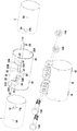
도 2는 도 1에 도시된 다양한 요소들의 분해 사시도이고;
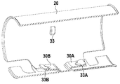
도 3은, 밀봉 슬리브의 축선과 직경을 포함하는 평면 III에서 절단하여 밀봉 슬리브의 내부를 나타내는, 밀봉 슬리브의 사시도이고;
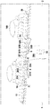
도 4는, 밀봉 슬리브의 축선을 포함하는 평면에서 절단하여 밀봉 슬리브와 상호작용하는 튜브들의 내부를 나타내는, 2개의 튜브를 함께 조립하기 위한 결합 장치의 부분 사시도이고;
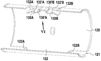
도 5는, 밀봉 슬리브에 대한 변형예를, 슬리브의 축선을 포함하는 평면에서 절단하여 나타내는 사시도이고;
도 6은 도 5의 VI 방향으로 밀봉 슬리브의 내부를 도시하는 도면이고;
도 7은, 2개의 튜브가 밀봉 슬리브와 함께 조립되는 방식을 나타내는, 다른 변형 실시예에 따른 밀봉 슬리브와 2개의 튜브의 단부를 도시하는 도면이고;
도 8은 밀봉 슬리브와 함께 조립된 튜브를 밀봉 슬리브의 축선을 포함하는 평면에서 절단하여 도시하는 도면이고;
도 9는, 클램핑 슬리브, 밀봉 슬리브 및 2개의 튜브를 분리 상태로 나타내는, 장치의 축선을 포함하는 평면에서 절단하여 도시하는 또 다른 변형 실시예의 분리 사시도이다.1 is a perspective view of a tube joining assembly of the present disclosure joining two tubes together, the assembly including a joining device operative to join the two tubes together;
2 is an exploded perspective view of the various elements shown in FIG. 1;
3 is a perspective view of the sealing sleeve, cut in plane III, including the axis and diameter of the sealing sleeve, showing the interior of the sealing sleeve;
4 is a partial perspective view of a coupling device for assembling two tubes together, showing the interior of the tubes cutting in a plane including the axis of the sealing sleeve and interacting with the sealing sleeve;
5 is a perspective view of a modification to the sealing sleeve, cut away in a plane including the axis of the sleeve;
6 shows the interior of the sealing sleeve in the VI direction of FIG. 5;
7 shows the sealing sleeve and the ends of the two tubes according to another variant embodiment, showing how the two tubes are assembled together with the sealing sleeve;
8 is a cut away view of a tube assembled with a sealing sleeve in a plane including the axis of the sealing sleeve;
FIG. 9 is an exploded perspective view of another alternative embodiment, cut away and showing in a plane including the axis of the device, showing the clamping sleeve, the sealing sleeve and the two tubes in a separated state.
도 1은 공통 축선(A)을 따라 정렬된 2개의 튜브(1 및 2)의 단부를 도시하며, 여기서 공통 축선은 또한 장치, 특히 클램핑 슬리브 및 밀봉 슬리브의 전체적인 축선이다. 2개의 튜브는 실질적으로 동일한 직경을 가지며, 클램핑 슬리브(10) 및 이 클램핑 슬리브(10) 내부에 위치되는 밀봉 슬리브(20)를 포함하는 결합 장치에 의해서 함께 결합된다. 예를 들어, 문헌 WO 00/75548에 기재된 바와 같이, 밀봉 슬리브는 축선방향으로 분할되어 있고, 그에 따라 반경방향으로 직립하는 어셈블리 립(assembly lips)에 의해 형성되는 축선방향 슬롯(11)을 갖는다. 클램핑을 달성하기 위해서, 서로 대향하는 어셈블리 립은 조임 수단, 특히 너트와 상호작용하는 볼트에 의해 함께 가까워질 수 있다. 본 예에서, 슬리브의 축선방향 길이를 고려하여, 2개의 조임 조립체가 제공된다. 따라서, 하나의 어셈블리 립은 서로를 분리하는 슬롯(12C)에 의해 이격되는 2개의 직립된 러그(lugs)(12A 및 12B)들을 포함하는 한편, 맞은편 어셉블리 립도 또한 슬롯(13C)에 의해 이격되어 있는 2개의 직립된 러그(13A 및 13B)들을 구비한다. 대향하는 러그들 각 쌍에 있어서, 조임 수단은, 러그들 중 하나에 대해 유지되는 머리부를 갖는 볼트(14A)와, 다른 하나의 러그에 대해 유지되는 너트(14B)를 포함한다.1 shows the ends of two
따라서, 클램핑 슬리브는 문헌 WO 2006/109002에 개시된 클램핑 슬리브와 실질적으로 유사하다.The clamping sleeve is thus substantially similar to the clamping sleeve disclosed in document WO 2006/109002.
전술한 바와 같이, 밀봉 슬리브는 클램핑 슬리브 내에 배치된다.As mentioned above, the sealing sleeve is disposed in the clamping sleeve.
밀봉 슬리브는 또한, 축선방향 슬롯(21)을 따라 축선방향으로 개방되는 슬리브의 형태로 구체화되고, 상기 슬롯을 형성하는 대향 가장자리부가 밀봉 장치를 구비한다는 점에서, 문헌 WO 2006/109002에 개시된 것과 유사할 수 있다. 이러한 밀봉 장치는, 예를 들어, 문헌 WO 00/75548 또는 문헌 WO 2006/109002에 개시된 바와 같이 이루어질 수 있다. 본 예에서, 밀봉 슬리브(20)의 대향 가장자리부는 2개의 탭(tabs)(24 및 24') 사이에 형성되는 혀부(tongue)(22) 및 노치(notch)(23)를 구비한다. 클램핑 슬리브의 조임 도중에, 밀봉 슬리브의 직경이 감소하여, 그에 따라 혀부(22)가 노치(23) 내로 전진하게 되고, 노치(22)의 측면 가장자리(22A 및 22B)에 형성되는 접촉 표면들 사이에서 밀봉 접촉이 발생되며 각각의 접촉 표면은 각각의 탭(24 및 24')에 형성됨을 이해할 수 있다. 따라서, 2개의 밀봉 배열(sealing arrangement)이 구체화되며, 이 배열은 축선방향으로 이격되어 있고 혀부의 가장자리(22A)와 탭(24)과의 접촉 표면 및 혀부의 가장자리(22B)와 탭(24')과의 접촉 표면 각각을 포함한다. 도시된 예에서, 문헌 WO 2006/109002에 기재된 바와 같이, 간극을 형성하는 오목부(25 및 25')는 혀부의 반대쪽으로 향하는 탭(24 및 24')의 측면에 각각 형성되어, 탭의 절첩을 촉진시키고 밀봉 접촉을 촉진시킨다.The sealing sleeve is also embodied in the form of a sleeve which opens axially along the
클램핑 슬리브(10) 내에 배치될 때, 밀봉 슬리브(20)는 상기 클램핑 슬리브에 대해 반경방향 및 축선방향으로 고정 유지된다. 본 예에서, 밀봉 슬리브는 그 외주에 위치되는 2개의 돌출부(26)를 가지며, 클램핑 슬리브(10)가 제공되는 보스(16)의 내측에 형성된 디쉬(dishes)에 맞물린다.When disposed in the clamping
결합 장치에는 튜브(1 및 2)에 사전-장착되는 사전-장착 수단이 구비되어 있다. 본 예에서, 각각의 상기 튜브는 다른 튜브를 향하는 단부 부근에 구멍(1A 및 2A)을 구비한다. 본 예에서, 이 구멍은 원형의 구멍이고, 구멍의 전방 가장자리부(1'A 및 2'A)는 유지표면(retaining surfaces)을 형성한다. 본 개시에 있어서, 전방 가장자리부는 다른 튜브를 향하는 튜브의 단부에 가까운 부분을 의미한다.The coupling device is equipped with pre-mounting means which are pre-mounted on the
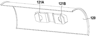
밀봉 슬리브는 튜브(1 및 2)의 유지표면 즉 전방 가장자리부(1'A 및 2'A)와 각각 상호작용하는 2개의 유지부재를 구비한다. 더욱 상세하게는, 도 2 내지 도 4에 보다 명확하게 도시된 바와 같이, 밀봉 슬리브(20)는 2개의 내부 탭(30A 및 30B)을 구비하며, 각각의 내부 탭은 외측으로 돌출하는 유지 포착부(retaining catch)(32A 또는 32B)를 각각 구비한다.The sealing sleeve has two retaining members which interact with the retaining surfaces of the
본 예에서, 특히 도 4에서, 내부 탭이 밀봉 슬리브의 내주벽(20A)에 대해 반경방향 내측으로 오프셋되어 있음을 알 수 있다. 상기 내주벽은 튜브의 외측 원통형 표면에 끼워맞춰질 수 있는 원통형 표면을 형성하며, 이 튜브는 상호 끼워맞춤 방식으로 밀봉 슬리브 내에 맞물려 들어간다. 도 4에 도시된 바와 같이, 내부 탭(30A 및 30B)의 외주면(S)과 슬리브의 내주벽과의 사이에는 반경방향 간격(E)이 형성되어 있다. 이러한 반경방향 간격(E)은 튜브의 두께(e)와 합치할 수 있다. 도 4에서 튜브(1 및 2)가 내부 탭(30A 및 30B) 아래에, 즉 탭(30A 및 30B) 중 하나와 밀봉 슬리브(20)의 내주벽(20A)과 사이에 삽입되어 가는 것을 알 수 있다.In this example, particularly in FIG. 4, it can be seen that the inner tab is radially inwardly offset with respect to the inner
그러나, 포착부(32A 및 32B)는 탭의 외주면(S)에 대해서 바깥쪽으로 돌출되어 있다. 도 4에 도시된 바와 같이, 튜브가 사전-장착 위치에 맞물릴 때, 포착부(32A 및 32B)는 튜브(1 및 2)의 구멍(1A 및 1B) 내로 각각 돌출된다. 포착부(32A 및 32B)는, 각각 탭(30A 및 30B)으로부터 절취되어, 그 자유단부가 탭(30A 및 30B)의 외주면(S)에 대해 반경방향 외측으로 돌출되도록 약간 구부러지는 혀부에 의해 형성된다.However, the
특히 도 3에서, 포착부(32A 및 32B)를 형성하도록 기능하는 절취부(cutout) (33A 및 33B)는 각각 반원 형상을 갖는다는 것을 알 수 있다. 따라서, 포착부(32A 및 32B)는 축선방향으로 볼록한 표면을 갖는다. 이는, 축선(A)방향 및 축선(A)에 수직인 방향을 포함하고 포착부를 통과하는 평면에서의 투영시, 상기 포착부는 볼록한 형상을 형성한다는 것을 의미한다. 본 예에서, 전술한 바와 같이, 절취부는 반원 형상을 갖는다. 물론, 다른 형상, 특히 타원형, 포물선형 등과 같은 형상이 적용될 수 있다. 유지표면(1'A 및 2'A)은 축선방향으로 오목한 표면이다. 본 예에서, 전술한 바와 같이, 상기 유지표면은 튜브 내의 구멍(1A 및 2A)의 전방 가장자리부에 의해 형성되며, 이 구멍은 원형 또는 타원형이다. 결과적으로, 포착부에 의해 형성된 유지부재와 유지표면 사이의 상호작용은 캠의 상호작용과 유사하다. 유지부재를 형성하는 포착부의 축선방향으로 볼록한 표면은, 튜브와 밀봉 슬리브(20)가 축선(A) 주위에서 서로에 대해 회전 운동할 때, 축선(A)을 향하여 포착부를 탄성적으로 가압하는 한편, 튜브가 밀봉 슬리브로부터 결합해제될 수 있도록 하는 방식으로, 유지표면(1'A 및 2'A)이 상기 포착부로부터 빠져나가도록 구멍(1A 및 1B)의 가장자리에 의해 형성될 수 있는 캠 표면을 형성한다.Particularly in FIG. 3, it can be seen that the
밀봉 슬리브가, 전술한 바와 같이, 클램핑 슬리브에 대해 반경방향으로 고정 유지되고 있는 한, 본 예에서 보스(16)의 내부에 형성되는 디쉬(dishes) 내로 들어가는 포착부(26)에 의해, 클램핑 슬리브를 유지하고 상기 클램핑 슬리브에 대해 각각의 튜브를 회전시킴으로써 장치를 분리시킬 수 있다는 것을 이해할 수 있다.As long as the sealing sleeve is held fixed radially relative to the clamping sleeve, as described above, by means of a
본 예에서, 내부 탭(30A 및 30B)은 밀봉 슬리브(20)의 축선방향 슬롯(21)을 형성하는 혀부(22)의 자유단부 부근에 형성된다. 보다 정확하게는, 도 2에서 상기 혀부가 공칭 직경(nominal diameter)을 유지하면서 원주방향으로 연장되는 연장부(22')를 갖는다는 것을 알 수 있을 것이다. 이 공칭 직경은 실질적으로 슬리브에 의해 형성되는 실린더의 직경이다. 도 2에서 탭(24)과 탭(24') 사이의 형성되는 노치(23)의 단부벽은 혀부(22)의 연장부(22')를 수용할 수 있는 후퇴부(setback) (23')를 갖는다는 것을 알 수 있다.In this example, the
상기 연장부(22')의 양측에는, 슬리브의 축선(A)에 평행하게 연장되는 절취부(21A 및 21B)가 형성된다. 상기 절취부는 혀부(22) 및 내부 탭(30A 및 30B)의 자유 가장자리부를 형성한다. 따라서, 상기 내부 탭은 혀부를 지나서 절취부(21A 및 21B)의 다른 쪽으로 연장된다. 각각의 내부 탭은 실질적으로 축선방향으로 연장된다. 내부 탭은 내측으로 접혀지고, 도 4에서 내부 탭은 연장부(22')에 연결되는 곳에서 각각 내부 단차부(30'A 및 30'B)가 형성되며, 단차부는 전술한 반경방향 간격(E)에 대응한다는 것을 알 수 있다.On both sides of the extension portion 22 ',
다시 말해서, 내부 탭(30A 및 30B)은 밀봉 슬리브의 벽에서 절단되고 안쪽으로 구부러져 있다. 포착부(32A 및 32B)는 그 자체가 상기 내부 탭으로부터 절단되어 구부러진다. 따라서, 본 예에서, 유지부재(본 예에서는: 포착부(32A 및 32B))는 밀봉 슬리브와 일체로 형성된다.In other words, the
전술한 단차부(30'A 및 30'B)는 튜브가 상호 끼워맞춤 방식으로 밀봉 슬리브(20)에 맞물릴 때 튜브(1 및 2)의 단부에 대한 받침(abutment) 표면을 형성한다. 따라서, 본 예에서, 받침 표면은 내부 탭(30A 및 30B)의 베이스에 형성되며, 이 베이스는 자유단부로부터 반대쪽이다. 또한 밀봉 슬리브의 내벽은 실질적으로 중간에 위치된 보스(33)를 갖는다는 점에 유의해야 한다. 폭방향으로, 이 보스(33)는 또한 튜브(1 및 2)를 위한 받침 표면으로서 기능할 수 있다.The steps 30'A and 30'B described above form an abutment surface for the ends of the
전술한 예에서, 밀봉 슬리브(20)는 각각 튜브(1 및 2) 중 하나와 상호작용하는 2개의 유지부재를 구비한다. 이는 2개의 튜브를 클램핑하여 밀봉 상태로 함께 연결하기 전에 2개의 튜브에 장치를 사전-장착할 수 있도록 한다. 물론 장치는, 예컨대, 튜브들 중 하나에만 장치를 사전-장착하도록, 전술한 유지부재들 중 하나와 유사한 하나의 유지부재만을 가지도록 제공될 수 있다.In the above example, the sealing
전술한 바와 같이, 상호연결은 밀봉(sealed), 즉 누설밀봉(leaktight) 상태이어야 한다. 따라서, 문헌 WO 2006/109002에 기재된 바와 같이, 전술한 밀봉 방치를 구비한 밀봉 슬리브의 슬롯(21)은, 클램핑 슬리브의 클램핑 슬롯(11)으로부터 이격되어 밀봉 슬리브의 연속된 영역 내에 위치한다. 상기 슬롯(21)은 따라서 클램핑 슬리브(10)에 의해 덮이며, 예를 들어, 도 1에 나타낸 영역(Z) 내에 위치된다. 따라서, 밀봉 장치의 혀부(24) 사이에 위치되는 노치(23) 전체는 클램핑 슬리브(10)에 의해 덮이고, 2개의 슬리브들은 서로 가압되므로, 밀봉이 보장된다. 유지부재는, 혀부(20)의 가장자리부(22A)와 탭(24) 사이, 그리고 혀부(20)의 가장자리부(22B)와 탭(24') 사이의 접촉 표면에 의해 형성되는 2개의 밀봉 장치 사이에서 축선방향으로 배치된다. 따라서, 튜브(1 및 2) 내의 구멍(1A 및 2A)은 또한 2개의 밀봉 장치 사이에 위치되며 튜브들 사이의 누출은 각각의 상기 밀봉 장치에 의해 형성되는 축선방향 세그먼트(segment)에 포획된다. 그러므로, 본 개시의 사전-장착은 2개의 튜브의 상호연결의 밀봉에 부정적인 영향을 미치지 않는다.As mentioned above, the interconnections must be sealed, i.e., leaktight. Thus, as described in document WO 2006/109002, the
변형 실시예를 도시하는 도 5 및 도 6에 대한 설명이 이어진다. 이 변형예는 도면부호 120으로 지시되는 밀봉 슬리브의 형태에 있어서만 도 1 내지 도 4에 도시된 실시예에와 상이하다. 이 밀봉 슬리브(120)에 대하여, 밀봉 장치는 전술한 것과 유사하다. 그러나, 본 변형예에서, 유지부재는 상기 밀봉 슬리브 내의 슬롯(121s)으로부터 이격되어 있는 밀봉 슬리브의 영역 내에 배치된다. 도 5에는 상기 슬롯의 가장자리들 중 하나를 형성하는 밀봉 혀부(122)가 도시되어 있다. 유지부재는 포착부(132A 및 132B)에 의해 형성되고, 그 자체는 내부 탭(130A 및 130B)에 형성되며, 이 포착부는 또한 상기 포착부를 명확하게 형성하도록 만들어지는 절취부의 형상, 예컨대 반원 형상에 대응하는 자유 가장자리부(132'A 및 132'B)에 의해 형성되는 축선방향으로 볼록한 표면을 가지며, 이전 실시형태에서와 같이, 포착부는 절단되어 세워지는 혀부의 형태를 갖는다. 내부 탭(130A 및 130B)은 밀봉 슬리브(120)의 절취부(121A 및 121B)에 의해 형성되어 내측으로 접혀진다. 따라서, 이들 내부 탭은 축선방향 슬롯(121)으로부터 이격되어 있는 슬리브(120)의 벽의 일부에 형성된다는 것 외에는 도 1 내지 도 4에 도시된 예와 거의 동일하다. 또한 도 5에는 튜브를 위한 받침 표면을 형성하기 위하여, 상기 내부 탭의 베이스에 형성되는 단차부(130'A 및 130'B)가 도시되어 있다. 포착부(132A 및 132B)는 밀봉 혀부(122)의 측면 가장자리부(122A)와 측면 가장자리부(122B) 사이에 축선방향으로 배치되어, 도 1 내지 도 4에 도시된 예에서와 같이, 유지부재는 밀봉 장치들 사이에 축선방향으로 배치되며, 그에 따라 어떠한 누출도 축선방향으로 규정되는 공간 내에 갇힌다.A description follows with respect to FIGS. 5 and 6 showing a variant embodiment. This variant differs from the embodiment shown in FIGS. 1 to 4 only in the form of a sealing sleeve, indicated at 120. For this sealing
전술한 변형예에서, 유지표면은 튜브(1 또는 2)의 구멍(1A 또는 2A)의 가장자리부에 형성된다. 또한 튜브의 내측표면으로부터 후퇴되는 그리고 유지 포착부가 맞물려 들어가는 후퇴부의 가장자리부에 형성될 수도 있다.In the above-described variant, the holding surface is formed at the edge of the
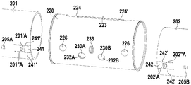
도 7 및 도 8을 참조하여 유지부재가 밀봉에 영향을 미치는 구멍의 가장자리부에 형성되는 변형예에 대한 설명이 이어진다. 도 7에는, 2개의 튜브(201 및 202)가 상호 끼워맞춤 방식으로 밀봉 슬리브(220)에 맞물리기 전의 상태가 도시되어 있다. 클램핑 슬리브는 도시되어 있지 않지만, 전술한 클램핑 슬리브(10)와 동일할 수 있다. 밀봉 슬리브(220)는 전술한 것과 유사한 밀봉 장치를 갖는 슬롯 (221)을 구비하며, 특히 노치(223)의 가장자리부를 형성하는 탭(224 및 224')을 갖는 것을 이해할 수 있다. 밀봉 슬리브(220)는 또한 외부 표면에 보스(226)를 가지며, 이 보스는 밀봉 슬리브가 축선방향으로 고정을 유지하고 클램핑 슬리브 내에서 회전할 수 있는, 도 2를 참조하여 설명된 보스(26)와 유사하다. 밀봉 슬리브(220)는 본 예에서 원형의 구멍인 2개의 구멍(230A 및 230B)을 구비한다는 것을 또한 알 수 있다. 튜브(201 및 202)와 관련하여, 포착부(201'A 및 202'A)가 제공되며, 도 8에 도시된 사전-장착 상태에서, 포착부는 밀봉 슬리브의 구멍(230A 및 230B)에 맞물리게 된다. 포착부(201'A 및 202'A)는 반경방향 외측으로 돌출되어 있다. 본 예에서, 이것들은 튜브로부터 절취되는 혀부의 형태로 구현되어, 축선방향으로 볼록하고 구멍(230A 및 230B)의 둥근 가장자리부와 상호작용하는 가장자리부(201"A 및 202"A)를 각각 갖는다. 따라서, 전술한 변형예에서와 같이, 튜브와 밀봉 슬리브의 상대적인 회전 운동은 유지부재와 유지표면 사이의 축선방향 유지 상호작용을 중단시킬 수 있다. 본 예에서, 포착부(201'A 및 202'A)는 튜브에 형성되며, 포착부가 형성되는 튜브의 부분(241 및 242)은 각각 축선방향 슬롯(241' 및 242') 사이에 형성된다. 이들 축선방향 슬롯은 튜브의 서로 마주하는 자유단부들에서 개구된다. 각각의 포착부는, 상기 축선방향 슬롯에 의해 형성되는 각각의 축선방향 탭(241 및 242)에 형성되며, 그에 따라 상기 축선방향 탭은 어느 정도 반경방향으로 탄성 변형될 수 있다. 이것은, 상호 끼워맞춤 방식으로 밀봉 슬리브(220)에 튜브를 장착할 때, 축선방향 탭이 안쪽으로 구부러질 수 있도록 하여, 상기 포착부가 전술한 축선방향 탭(241 및 242)의 탄성 변형의 영향 하에 개구부 즉 구멍(230A 및 230B) 내로 스냅-고정될 때까지, 포착부(201'A 및 202'A)가 밀봉 슬리브(220) 내로 전진할 수 있게 한다. 본 예에서, 유지부재는 구멍(230A 및 230B)의 후방 가장자리부(232A 및 232B)에 의해 형성된다. 밀봉 슬리브의 보스(233)의 내부면은 튜브에 대한 받침부(abutment)로서 기능할 수 있다.With reference to FIGS. 7 and 8, a description will be given of a modification in which the holding member is formed at the edge portion of the hole that affects the sealing. In FIG. 7, the state before the two
도 9를 참조하여, 유지부재가 클램핑 슬리브(310)에 설치되는 다른 변형예에 대한 설명이 이어진다. 도 9에는 클램핑 슬리브(310), 밀봉 슬리브(320) 및 튜브(301 및 302)를 클램핑 슬리브의 축선방향 슬롯(311)을 통과하는 축선방향 평면에서 절단한 분리 단면도가 도시되어 있으며, 조임 러그(314A 및 314B)가 도시되어 있으나; 반대로, 밀봉 슬리브(320)의 축선방향 슬롯 및 밀봉 장치는 도 9에 도시되어 있지 않다. 튜브는 도 1 내지 도 4에 도시된 것과 동일할 수 있고, 그것과 같이, 개구(301A 및 302A) 및 유지표면을 형성하는 전방 가장자리부(301'A 및 302'A)를 구비한다. 유지부재는 도 1 내지 도 6에 도시된 예와 유사하며, 따라서 유지부재는 내부 탭(330A 및 330B)으로부터 절취되는 혀부에 의해 형성되는 포착부(332A 및 332B)의 형태로 구체화된다. 그러나, 상기 내부 탭은 클램핑 슬리브(310)의 내주에 고정되는 유지요소(329)에 형성된다. 이 유지요소(329)는, 클램핑 슬리브의 내부 표면에 가압되어, 예컨대 용접에 의해 또는 임의의 적절한 수단에 의해 상기 내부 표면에 고정되는 베이스(329A)를 가지며, 내부 탭은 상기 베이스(329A)에 대해 내측으로 접힌다.With reference to FIG. 9, a description will be given of another modification in which the holding member is installed in the clamping
밀봉 슬리브는, 이 밀봉 슬리브가 클램핑 슬리브 내에 배치될 때, 내부 탭(330A 및 330B)이 통과하는 윈도(window)(327)를 갖는다. 내부 탭의 외부면과 클램핑 슬리브(310)의 내주 사이의 거리(D)는 도 4를 참조하여 전술한 반경방향 간격(E)과 밀봉 슬리브(320)의 두께의 합과 실질적으로 동일하다. 따라서, 일단 내부 탭이 윈도(327) 내에 배치되면, 도 1 내지 도 4, 그리고 도 5 및 도 6에 도시된 예에서의 내부 탭(30A 및 30B 또는 130A 및 130B)과 동일한 방식으로 밀봉 슬리브 내부로 돌출된다. 튜브는 전술한 예에서와 동일한 방식으로 사전-장착되기 위하여 정위치되며, 하나의 슬리브가 다른 슬리브 내에 조립된 2개의 슬리브의 조립체 내로 튜브가 축선방향으로 삽입될 수 있으며, 이 삽입은 포착부(332A 및 332B)를 구멍(301A 및 302A)으로 볼 수 있을 때까지 수행된다. 내부 탭(330A 및 330B)은, 튜브의 단부를 위한 받침 표면으로서 기능할 수 있는 실질적으로 반경방향인 벽(330'A 및 330'B)을 형성하는 접힘부를 통해 베이스(329A)에 연결된다.The sealing sleeve has a
물론, 튜브를 유지하기 위해 작용하는 모든 수단, 즉 유지부재, 윈도(327) 및 구멍(301A 및 302A)은 상기 슬리브의 벽에 의해 폐쇄되는 클램핑 슬리브(310)의 영역 내에 있으며, 그에 따라 상기 영역에 있어서의 밀봉을 보장한다. 또한, 이전 도면에 도시된 바와 같이, 밀봉 수단을 구비하는 밀봉 슬리브의 축선방향 슬롯은 또한 그 벽에 의해 폐쇄되는 클램핑 슬리브의 영역 내에 있다. 윈도(327) 이외에는, 밀봉 슬리브(320)는 문헌 WO 2006/109002에 개시된 밀봉 슬리브와 유사할 수 있다.Of course, all the means acting to hold the tube, i.e. the retaining member, the
이전 도면에 도시된 예에서와 동일한 방식으로, 튜브들을 모두 유지하도록 작용하는 2개의 유지부재(332A 및 332B)가 설명되었지만, 어떤 부착 방향이 선택되는지에 따라, 상기 2개의 유지부재들 중 하나 또는 다른 하나와 상호작용할 수 있는 유지표면을 가지도록 튜브들 중 하나를 준비하거나, 또는, 예컨대 도 9를 참조하여 설명된 유형의, 단지 하나의 유지부재만을 가지도록 클램핑 슬리브를 준비할 수 있다.In the same manner as in the example shown in the previous figures, two retaining
유지 포착부(332A 및 332B)는 둥근 절취부로 형성되고, 따라서 클램핑 슬리브와 튜브 사이의 상대 회전에 의해 분리가 가능하도록, 유지표면과 상호작용할 수 있는 캠 표면을 갖는다는 것이 주목된다.It is noted that the retention catches 332A and 332B are formed as round cuts and thus have a cam surface that can interact with the retention surface so that separation is possible by relative rotation between the clamping sleeve and the tube.
전술한 예 모두에 있어서, 결합 장치는 유지부재의 위치를 나타내는 외부 표시부(markers)를 갖도록 준비될 수 있다. 따라서, 도 1에서 클램핑 슬리브(10)는 축선방향 단부에 2개의 표시부(15A 및 15B)를 갖는다는 것을 알 수 있다. 이 표시부는 유지부재(32A 및 32B)의 위치와 축선방향으로 정렬되며, 이 위치는, 일단 밀봉 슬리브가 클램핑 슬리브 내부에 있다면, 밀봉 슬리브는 전술한 바와 같이 클램핑 슬리브(10) 내에서 회전식으로 고정 유지됨을 결정한다는 것을 상기시킨다. 이것은, 튜브가 상호 끼워맞춤 방식으로 장치에 맞물리는 동안, 구멍(1A 및 2A)을 각각의 표시부(15A 및 15B)와 정렬시켜, 유지표면이 유지부재에 대해 정확하게 각도적으로 위치되도록 하고 이러한 요소들이 서로 적절하게 상호작용하는 것을 보장하도록 한다.In all of the above examples, the coupling device may be prepared to have external markers indicating the position of the holding member. Thus, in Figure 1 it can be seen that the clamping
표시부는 임의의 적절한 형태, 예컨대 노치, 보스, 컬러 라인 등으로 구체화될 수 있다.The indicators may be embodied in any suitable form, such as notches, bosses, color lines, and the like.
동일한 유형의 표시부가, 밀봉 슬리브의 구멍(230A 및 230B)과 축선방향으로 정렬됨으로써, 도 7 및 도 8의 변형예에 제공될 수 있다.The same type of indicator can be provided in the variant of FIGS. 7 and 8 by being axially aligned with the
도 9는 또한 포착부(332A 및 332B)와 정렬되는 이러한 표시부(315A 및 315B)의 위치를 도시한다.9 also shows the position of these
또한, 튜브는 유지표면의 위치를 나타내는 외부 표시부를 가지도록 준비될 수 있다. 따라서, 도 1 및 도 2에는, 튜브(1)에 대하여 표시부(5A), 그리고 튜브(2)에 대하여 표시부(5B)가 도시되어 있다. 이들 표시부는 튜브가 상호 끼워맞춤 방식으로 결합 장치에 맞물릴 때 가시성을 유지하는 방식으로 튜브의 단부로부터 거리를 두고 형성된다. 표시부(5A 및 5B)가 표시부(15A 및 15B)와 정렬될 때, 작업자는 튜브가 장치 내에 정확하게 위치되어 있다는 것을 알 수 있다. 표시부(5A 및 5B)는 예를 들어 보스, 후퇴부(setbacks) 또는 컬러 마킹에 의해 임의의 적절한 방식으로 구체화될 수 있다. 이러한 표시부(205A 및 205B, 그리고 305A 및 305B)는 또한 도 7 및 도 9에 도시되어 있다.The tube may also be prepared to have an external indicator indicating the position of the holding surface. Therefore, in FIG. 1 and FIG. 2, the
전술한 다양한 예에 있어서, 유지부재 및 유지표면은 탄성적인 스냅-고정(snap-fastening) 또는 클리핑(clipping)에 의해 상호작용한다. 더욱 상세하게는, 도 1 내지 도 6 및 도 9에 도시된 예에서, 밀봉 슬리브 또는 클램핑 슬리브에 설치되는 유지부재는 튜브(또는 적어도 하나의 튜브)를 결합 장치에 삽입할 수 있도록 탄성적으로 변형되며, 유지표면에 대항하여 유지되도록 다시 자유 형태(free shapes)를 취한다. 도 7 및 도 8에 도시된 변형예에서, 튜브들(또는 하나의 튜브)이/가 결합 장치 내로 삽입되는 동안 튜브에 설치된 유지표면은 탄성적으로 변형되고, 유지부재를 형성하는 구멍 내로 되돌아가 포착된다.In the various examples described above, the retaining member and the retaining surface interact by elastic snap-fastening or clipping. More specifically, in the examples shown in FIGS. 1-6 and 9, the retaining member installed in the sealing sleeve or the clamping sleeve is elastically deformed to insert the tube (or at least one tube) into the coupling device. And again take free shapes to hold against the holding surface. In the variant shown in FIGS. 7 and 8, the holding surface installed in the tube is elastically deformed and is returned to the hole forming the holding member while the tubes (or one tube) are inserted into the coupling device. Is captured.
Claims (21)
상기 결합 장치는, 2개의 튜브의 대향 단부 주위에 배치되도록 구성되는 밀봉 슬리브(20; 120; 220; 320)와, 상기 밀봉 슬리브가 내부에서 연장되는 클램핑 슬리브(10; 310)를 포함하며;
밀봉 슬리브(20; 120; 220; 320) 및 클램핑 슬리브(10; 310)에 의해 구성되는 요소들 중 하나는, 튜브들 중 하나의 유지표면(1'A, 2'A; 201'A, 202'A; 301'A, 302'A)과 상호작용하여 클램핑 슬리브 내에서 축선방향 유지하도록 구성되는 적어도 하나의 유지부재(32A, 32B; 132A, 132B; 232A, 232B; 332A, 332B)를 가지며, 상기 유지표면은 상기 클램핑 슬리브에 의해 덮이는 것을 특징으로 하는 결합 장치.As a joining device for joining two aligned tubes 1, 2; 201, 202; 310, 302 together in a sealed manner,
The coupling device comprises a sealing sleeve (20; 120; 220; 320) configured to be disposed around opposite ends of the two tubes and a clamping sleeve (10; 310) extending therein;
One of the elements constituted by the sealing sleeve 20; 120; 220; 320 and the clamping sleeve 10; 310 is one of the retaining surfaces 1'A, 2'A;201'A, 202 of one of the tubes. At least one retaining member 32A, 32B; 132A, 132B; 232A, 232B; 332A, 332B, configured to interact axially within the clamping sleeve in interaction with 'A;301'A,302'A, And the retaining surface is covered by the clamping sleeve.
상기 유지부재(32A, 32B; 132A, 132B; 232A, 232B; 332A, 332B)는, 상기 유지표면(1'A, 2'A; 201'A, 202'A; 301'A, 302'A)과 상호작용하도록 구성되는 한편, 상기 유지표면을 갖는 튜브(1, 2; 201, 202; 301, 302) 및 상기 유지부재를 갖는 상기 요소들 중 상기 하나가 서로에 대해 회전 이동할 때 축선방향 유지를 해제시키는 캠 표면을 가지는 결합 장치.The method according to claim 1,
The holding members 32A, 32B; 132A, 132B; 232A, 232B; 332A, 332B have the holding surfaces 1'A, 2'A;201'A,202'A;301'A,302'A. And axial retention as the tube 1, 2; 201, 202; 301, 302 with the retaining surface and the one of the elements with the retaining member rotate relative to each other. Coupling device having a cam surface to release.
상기 밀봉 슬리브(20; 120; 220; 320)는 축선방향으로 이격되어 있는 2개의 밀봉 장치(24, 22A; 24', 22B)를 가지며, 상기 유지부재(32A, 32B; 132A, 132B; 232A, 232B; 332A, 332B)는 2개의 상기 밀봉 장치 사이에서 축선방향으로 배치되는, 결합 장치.The method according to claim 1 or 2,
The sealing sleeves 20; 120; 220; 320 have two sealing devices 24, 22A; 24 ', 22B spaced apart in the axial direction, and the holding members 32A, 32B; 132A, 132B; 232A, 232B; 332A, 332B are disposed axially between two said sealing devices.
상기 유지부재(32A, 32B; 132A, 132B; 232A, 232B)는, 상기 밀봉 슬리브(20; 120; 220)에 설치되거나 상기 밀봉 슬리브와 일체로 형성되며, 상기 클램핑 슬리브(10)에 의해 덮이는 상기 밀봉 슬리브의 영역 내에 위치되는, 결합 장치.The method according to any one of claims 1 to 3,
The holding members 32A, 32B; 132A, 132B; 232A, 232B are installed in the sealing sleeve 20; 120; 220 or integrally formed with the sealing sleeve, and are covered by the clamping sleeve 10. Is located within the area of the sealing sleeve.
상기 유지부재(332A, 332B)는 상기 클램핑 슬리브(310) 내에 장착되어 상기 밀봉 슬리브(320) 내의 윈도(327)를 통과하는 결합 장치.The method according to any one of claims 1 to 3,
The retaining member (332A, 332B) is mounted in the clamping sleeve (310) and passes through a window (327) in the sealing sleeve (320).
상기 유지부재는 상기 밀봉 슬리브(20; 120; 320) 내에서 연장되는 포착부(32A, 32B; 132A, 132B; 332A, 332B)를 포함하며, 상기 포착부는 축선방향으로 볼록한 표면(32'A, 32'B)을 선택적으로 가지는 결합 장치.The method according to any one of claims 1 to 5,
The retaining member includes catches 32A, 32B; 132A, 132B; 332A, 332B extending in the sealing sleeve 20; 120; 320, the catches having an axially convex surface 32'A, Coupling device optionally having 32'B).
상기 밀봉 슬리브(20; 120)는, 상기 밀봉 슬리브(20; 120)의 벽에 대해 반경방향 내측으로 오프셋되어 상기 벽과의 사이에서 반경방향 간격(E)을 형성하는 적어도 하나의 내부 탭(30A, 30B; 130A, 130B)을 가지는 결합 장치.The method according to any one of claims 1 to 6,
The sealing sleeve 20; 120 is at least one inner tab 30A radially offset radially inward with respect to the wall of the sealing sleeve 20; 120 to form a radial gap E between the wall. , 30B; 130A, 130B).
상기 내부 탭(30A, 30B; 130A, 130B)은 외측으로 돌출하는 유지 포착부(32A, 32B; 132A, 132B)를 가지며, 상기 유지 포착부는 상기 내부 탭으로부터 선택적으로 절취되는 결합 장치.The method according to claim 7,
The inner tab (30A, 30B; 130A, 130B) has a retaining catch (32A, 32B; 132A, 132B) that protrudes outward, the retaining catch being selectively cut away from the inner tab.
상기 내부 탭(30A, 30B; 130A, 130B)은 상기 밀봉 슬리브(20; 120)의 벽으로부터 절취되어 내측으로 접히는 결합 장치.The method according to claim 7 or 8,
The inner tab (30A, 30B; 130A, 130B) is cut away from the wall of the sealing sleeve (20; 120) and folded inward.
튜브(1, 2)들 중 하나의 단부에 대한 적어도 하나의 받침 표면(30'A, 30'B; 130'A, 130'B; 233; 330'A, 330'B)을 가지는 결합 장치.The method according to any one of claims 1 to 9,
Coupling device having at least one support surface (30'A, 30'B;130'A,130'B;233;330'A,330'B) at one end of one of the tubes (1, 2).
상기 받침 표면(30'A, 30'B; 130'A, 130'B)은 내부 탭(30A, 30B; 130A, 130B)의 베이스에 형성되며, 상기 베이스는 내부 탭의 자유단부로부터 반대쪽에 있는 결합 장치.The method according to claim 10 taken in combination with any one of claims 7 to 9,
The backing surfaces 30'A, 30'B;130'A,130'B are formed in the base of the inner tabs 30A, 30B; 130A, 130B, which base is opposite from the free end of the inner tab. Coupling device.
상기 유지부재의 위치를 나타내는 외부 표시부(15A, 15B; 315A, 315B)를 가지는 결합 장치.The method according to any one of claims 1 to 11,
And an outer display portion (15A, 15B; 315A, 315B) indicating the position of the holding member.
상기 유지부재(32A, 32B; 132A, 132B; 232A, 232B; 332A, 332B)를 갖는 상기 요소(20, 120; 220; 310)는 축선방향으로 이격되어 있는 2개의 유지부재를 가지는 결합 장치.The method according to any one of claims 1 to 12,
The element (20, 120; 220; 310) having the retaining members (32A, 32B; 132A, 132B; 232A, 232B; 332A, 332B) has two retaining members spaced apart in the axial direction.
상기 밀봉 슬리브(20, 120; 220; 320)는 개방형(open type)이며, 축선방향으로 이격되어 있는 2개의 밀봉 장치를 통해 함께 연결되는 2개의 대향 단부를 가지는 결합 장치.The method according to any one of claims 1 to 13,
The sealing sleeve (20, 120; 220; 320) is open type and has two opposing ends connected together through two axially spaced sealing devices.
2개의 밀봉 장치(22A, 22B) 각각은, 혀부(22)의 가장자리부 상에 그리고 노치의 가장자리부(24, 24') 상에 각각 위치되는 2개의 접촉표면을 가지는 결합 장치.The method according to claim 14,
Each of the two sealing devices (22A, 22B) has two contact surfaces respectively located on the edge of the tongue (22) and on the edges (24, 24 ') of the notch.
상기 제1 튜브는 상기 클램핑 슬리브(10; 310) 내에서 상기 유지부재(32A; 132A; 232A; 332A)와 상호작용하도록 구성되는 유지표면(1'A; 201'A; 301'A)을 가지는 튜브 결합 조립체.A tube joining assembly comprising a joining device according to claim 1 and a first tube (1; 201; 301) aligned with a second tube (2; 202; 302) for joining through the joining device. as,
The first tube has a holding surface 1'A;201'A;301'A configured to interact with the retaining members 32A; 132A; 232A; 332A in the clamping sleeve 10; 310. Tube coupling assembly.
상기 유지표면(1'A)은 상기 제1 튜브(1)의 내부표면으로부터 후퇴되어 형성되는 후퇴부의 가장자리부 상에, 또는 상기 제1 튜브 내의 구멍(1A)의 가장자리부 상에 형성되는 튜브 결합 조립체.The method according to claim 16,
The retaining surface 1'A is formed on the edge of the recess, which is formed by being retracted from the inner surface of the first tube 1, or on the edge of the hole 1A in the first tube. Assembly.
상기 결합 장치는 청구항 7에 따른 것이며, 상기 제1 튜브(1)의 두께는 상기 반경방향 간격(E) 내에 수용되는 튜브 결합 조립체.The method according to claim 16 or 17,
The coupling device according to claim 7, wherein the thickness of the first tube (1) is received in the radial spacing (E).
상기 유지부재(232A, 232B)는 상기 밀봉 슬리브(220) 내의 구멍(230A, 230B)의 가장자리부에 형성되며, 상기 유지표면(201'A)은 상기 제1 튜브(201)의 외측표면에 대해 돌출되어 형성되는 튜브 결합 조립체.The method according to claim 16,
The retaining members 232A, 232B are formed at the edges of the holes 230A, 230B in the sealing sleeve 220, and the retaining surface 201'A is formed with respect to the outer surface of the first tube 201. Protruding tube assembly assembly.
상기 결합 장치는 청구항 13에 따른 것이며, 상기 튜브 결합 조립체는 제2 튜브(2; 202; 302)를 더 포함하며, 각각의 상기 제1 및 제2 튜브는 각각의 상기 유지부재와 상호작용하도록 구성되는 유지표면(1'A, 2'A; 201'A, 202'A; 301'A, 302'A)을 가지는 튜브 결합 조립체.The method according to any one of claims 16 to 19,
The coupling device according to claim 13, wherein the tube coupling assembly further comprises a second tube (2; 202; 302), each said first and second tube being configured to interact with each said retaining member. And a retaining surface (1'A, 2'A;201'A,202'A;301'A,302'A).
상기 제1 및 제2 튜브(1, 2; 201, 202; 301, 302) 중 적어도 하나는 상기 유지표면의 위치를 나타내는 외부 표시부(5A, 5B; 205A, 205B; 305A, 305B)를 가지는 튜브 결합 조립체.The method according to any one of claims 16 to 20,
At least one of the first and second tubes (1, 2; 201, 202; 301, 302) has a tube coupling having an external display portion (5A, 5B; 205A, 205B; 305A, 305B) indicating the position of the holding surface. Assembly.
Applications Claiming Priority (3)
| Application Number | Priority Date | Filing Date | Title |
|---|---|---|---|
| FR1751002 | 2017-02-07 | ||
| FR1751002A FR3062702B1 (en) | 2017-02-07 | 2017-02-07 | DEVICE FOR COUPLING TWO TUBES WITH PRE-ASSEMBLY |
| PCT/FR2018/050285 WO2018146409A1 (en) | 2017-02-07 | 2018-02-06 | Device for coupling two tubes with pre-assembly |
Publications (1)
| Publication Number | Publication Date |
|---|---|
| KR20190113947A true KR20190113947A (en) | 2019-10-08 |
Family
ID=58739100
Family Applications (1)
| Application Number | Title | Priority Date | Filing Date |
|---|---|---|---|
| KR1020197026389A KR20190113947A (en) | 2017-02-07 | 2018-02-06 | Device for joining two tubes in pre-assembly |
Country Status (10)
| Country | Link |
|---|---|
| US (1) | US11415250B2 (en) |
| EP (1) | EP3580486B1 (en) |
| JP (1) | JP7138120B2 (en) |
| KR (1) | KR20190113947A (en) |
| CN (1) | CN110268185B (en) |
| BR (1) | BR112019015839A2 (en) |
| ES (1) | ES2901412T3 (en) |
| FR (1) | FR3062702B1 (en) |
| RU (1) | RU2759573C2 (en) |
| WO (1) | WO2018146409A1 (en) |
Families Citing this family (2)
| Publication number | Priority date | Publication date | Assignee | Title |
|---|---|---|---|---|
| DK178821B1 (en) * | 2015-07-10 | 2017-02-27 | Landmeco Ølgod As | A process for separating bar assembly and retention of the two circular cylindrical pipe ends, the system for joining two pipe ends having the same outer diameters and the same wall thickness as well as the use of such a system |
| FR3095682B1 (en) * | 2019-05-03 | 2023-01-06 | Caillau | Clamping device comprising a collar and a seal |
Family Cites Families (17)
| Publication number | Priority date | Publication date | Assignee | Title |
|---|---|---|---|---|
| US4380348A (en) * | 1981-02-18 | 1983-04-19 | Clamp-All Corp. | Pipe clamping assembly |
| DE3731630A1 (en) * | 1987-09-19 | 1989-03-30 | Hilti Ag | DRILLING TOOL |
| JPH07190260A (en) * | 1993-12-24 | 1995-07-28 | Takenaka Komuten Co Ltd | Housing type pipe joint |
| FR2794517B1 (en) | 1999-06-02 | 2001-08-24 | Caillau Ets | DEVICE FOR THE SEALED CONNECTION OF TWO SMOOTH TUBES |
| KR101174298B1 (en) | 2003-11-07 | 2012-08-16 | 노마 유.에스. 홀딩 엘엘씨 | Pipe clamp with integral latch |
| US7490871B2 (en) * | 2004-02-26 | 2009-02-17 | Breeze-Torca Products, Llc | Pipe clamp with button engagement hole |
| AU2005248402A1 (en) * | 2004-05-25 | 2005-12-08 | Breeze-Torca Products, Llc | Ribbed pipe clamp with sealing sleeve |
| FR2884582B1 (en) * | 2005-04-13 | 2010-01-08 | Caillau Ets | DEVICE FOR THE SEALED COUPLING OF TWO SMOOTH TUBES |
| JP2008190700A (en) * | 2007-02-07 | 2008-08-21 | Kitz Corp | Valve with diameter-reduced joint part |
| FR2920495B1 (en) | 2007-09-05 | 2011-07-08 | Saint Gobain Pont A Mousson | CLAMP COLLAR ASSEMBLY, CLAMP CLAMP AND CORRESPONDING TUBULAR CONNECTION. |
| DE102008018426A1 (en) * | 2008-04-10 | 2009-10-15 | Mahle International Gmbh | coupling device |
| FR2933756B1 (en) * | 2008-07-10 | 2013-06-14 | Caillau Ets | CLAMPING DEVICE COMPRISING A NECKLACE |
| JP5325547B2 (en) * | 2008-11-26 | 2013-10-23 | 株式会社パイオラックス | Check valve for fuel tank |
| ITTO20110668A1 (en) * | 2011-07-25 | 2013-01-26 | Elbi Int Spa | SYSTEM FOR REALIZING A QUICK CONNECTION OF A TUBE WITH A RECEIVING BODY, PARTICULARLY FOR USE IN MURAL AND SIMILAR BOILERS |
| JP2015511301A (en) | 2012-02-10 | 2015-04-16 | ストラブ ウェーク アーゲー | Pipe fitting |
| CN205331664U (en) * | 2016-01-18 | 2016-06-22 | 常州盛德无缝钢管有限公司 | Seamless steel pipe |
| CN205402048U (en) * | 2016-03-28 | 2016-07-27 | 长城汽车股份有限公司 | Pipeline connecting component |
-
2017
- 2017-02-07 FR FR1751002A patent/FR3062702B1/en active Active
-
2018
- 2018-02-06 WO PCT/FR2018/050285 patent/WO2018146409A1/en unknown
- 2018-02-06 US US16/482,910 patent/US11415250B2/en active Active
- 2018-02-06 BR BR112019015839-1A patent/BR112019015839A2/en not_active Application Discontinuation
- 2018-02-06 EP EP18707087.5A patent/EP3580486B1/en active Active
- 2018-02-06 CN CN201880010452.4A patent/CN110268185B/en active Active
- 2018-02-06 KR KR1020197026389A patent/KR20190113947A/en not_active Application Discontinuation
- 2018-02-06 ES ES18707087T patent/ES2901412T3/en active Active
- 2018-02-06 JP JP2019563694A patent/JP7138120B2/en active Active
- 2018-02-06 RU RU2019127998A patent/RU2759573C2/en active
Also Published As
| Publication number | Publication date |
|---|---|
| RU2759573C2 (en) | 2021-11-15 |
| JP7138120B2 (en) | 2022-09-15 |
| CN110268185A (en) | 2019-09-20 |
| WO2018146409A1 (en) | 2018-08-16 |
| US11415250B2 (en) | 2022-08-16 |
| EP3580486A1 (en) | 2019-12-18 |
| ES2901412T3 (en) | 2022-03-22 |
| EP3580486B1 (en) | 2021-09-22 |
| RU2019127998A (en) | 2021-03-09 |
| FR3062702B1 (en) | 2020-08-21 |
| US20200011458A1 (en) | 2020-01-09 |
| CN110268185B (en) | 2022-11-04 |
| RU2019127998A3 (en) | 2021-05-21 |
| JP2020507043A (en) | 2020-03-05 |
| BR112019015839A2 (en) | 2020-03-31 |
| FR3062702A1 (en) | 2018-08-10 |
Similar Documents
| Publication | Publication Date | Title |
|---|---|---|
| RU2395747C1 (en) | Fluid medium main line coupling | |
| KR20140100896A (en) | Profile clamp with pre-positioner | |
| KR20190113947A (en) | Device for joining two tubes in pre-assembly | |
| JP4020122B2 (en) | Plug-in coupling that joins fluid pipe to pipe | |
| BRPI0308842B1 (en) | Lubricant seal assembly, installation method of said lubricant seal assembly | |
| KR20180037595A (en) | A clamping system with controlled angular positioning for connecting together two tubes | |
| RU2568003C2 (en) | Thrust cap | |
| RU2010154174A (en) | TUBE CLAMP | |
| FR2929662A1 (en) | SYSTEM AND METHOD FOR RETAINING TURBINE BLADE. | |
| CN108700234A (en) | Including the proximate matter fixture of sealing element, for proximate matter fixture sealing element and include the conduit connection component of this proximate matter fixture | |
| JP2008539386A (en) | Shaft seal with integrated removal mechanism | |
| RU2723647C2 (en) | Plug connector for connection of pipelines for liquid or gaseous media | |
| JP2019090526A (en) | Profile clamp with seal member | |
| JP4088922B2 (en) | Fitting | |
| EA027155B1 (en) | Locking device for vacuum cleaner suction pipe | |
| KR20200074904A (en) | Tightening device comprising a belt and a sealing ring | |
| JP6796141B2 (en) | Hose clamp | |
| ES2540238T3 (en) | Staple for tubes with spring washer | |
| JP7086226B2 (en) | Right angle electrical connector | |
| KR102090313B1 (en) | Duct socket | |
| JP2020507043A5 (en) | ||
| JP5867865B2 (en) | Cylinder mounting structure | |
| FR2908710A1 (en) | Loud speaker fixing device for use in vehicle, has holding unit traversing corresponding passages in vehicle inner panel and engaging with locking unit after rotational movement of speaker unit in circumferential direction relative to panel | |
| KR20200127895A (en) | Clamping device comprising a collar and a seal | |
| CN111936780B (en) | Clamp apparatus |
Legal Events
| Date | Code | Title | Description |
|---|---|---|---|
| A201 | Request for examination | ||
| E902 | Notification of reason for refusal | ||
| E601 | Decision to refuse application |