KR20190110436A - Weld signature analysis for weld quality determination - Google Patents
Weld signature analysis for weld quality determination Download PDFInfo
- Publication number
- KR20190110436A KR20190110436A KR1020190025145A KR20190025145A KR20190110436A KR 20190110436 A KR20190110436 A KR 20190110436A KR 1020190025145 A KR1020190025145 A KR 1020190025145A KR 20190025145 A KR20190025145 A KR 20190025145A KR 20190110436 A KR20190110436 A KR 20190110436A
- Authority
- KR
- South Korea
- Prior art keywords
- weld
- symbol
- shape
- welding
- parameter
- Prior art date
Links
Images
Classifications
-
- B—PERFORMING OPERATIONS; TRANSPORTING
- B23—MACHINE TOOLS; METAL-WORKING NOT OTHERWISE PROVIDED FOR
- B23K—SOLDERING OR UNSOLDERING; WELDING; CLADDING OR PLATING BY SOLDERING OR WELDING; CUTTING BY APPLYING HEAT LOCALLY, e.g. FLAME CUTTING; WORKING BY LASER BEAM
- B23K9/00—Arc welding or cutting
- B23K9/16—Arc welding or cutting making use of shielding gas
-
- B—PERFORMING OPERATIONS; TRANSPORTING
- B23—MACHINE TOOLS; METAL-WORKING NOT OTHERWISE PROVIDED FOR
- B23K—SOLDERING OR UNSOLDERING; WELDING; CLADDING OR PLATING BY SOLDERING OR WELDING; CUTTING BY APPLYING HEAT LOCALLY, e.g. FLAME CUTTING; WORKING BY LASER BEAM
- B23K9/00—Arc welding or cutting
- B23K9/095—Monitoring or automatic control of welding parameters
- B23K9/0953—Monitoring or automatic control of welding parameters using computing means
-
- B—PERFORMING OPERATIONS; TRANSPORTING
- B23—MACHINE TOOLS; METAL-WORKING NOT OTHERWISE PROVIDED FOR
- B23K—SOLDERING OR UNSOLDERING; WELDING; CLADDING OR PLATING BY SOLDERING OR WELDING; CUTTING BY APPLYING HEAT LOCALLY, e.g. FLAME CUTTING; WORKING BY LASER BEAM
- B23K31/00—Processes relevant to this subclass, specially adapted for particular articles or purposes, but not covered by only one of the preceding main groups
- B23K31/02—Processes relevant to this subclass, specially adapted for particular articles or purposes, but not covered by only one of the preceding main groups relating to soldering or welding
-
- B—PERFORMING OPERATIONS; TRANSPORTING
- B23—MACHINE TOOLS; METAL-WORKING NOT OTHERWISE PROVIDED FOR
- B23K—SOLDERING OR UNSOLDERING; WELDING; CLADDING OR PLATING BY SOLDERING OR WELDING; CUTTING BY APPLYING HEAT LOCALLY, e.g. FLAME CUTTING; WORKING BY LASER BEAM
- B23K31/00—Processes relevant to this subclass, specially adapted for particular articles or purposes, but not covered by only one of the preceding main groups
- B23K31/12—Processes relevant to this subclass, specially adapted for particular articles or purposes, but not covered by only one of the preceding main groups relating to investigating the properties, e.g. the weldability, of materials
- B23K31/125—Weld quality monitoring
-
- B—PERFORMING OPERATIONS; TRANSPORTING
- B23—MACHINE TOOLS; METAL-WORKING NOT OTHERWISE PROVIDED FOR
- B23K—SOLDERING OR UNSOLDERING; WELDING; CLADDING OR PLATING BY SOLDERING OR WELDING; CUTTING BY APPLYING HEAT LOCALLY, e.g. FLAME CUTTING; WORKING BY LASER BEAM
- B23K9/00—Arc welding or cutting
- B23K9/095—Monitoring or automatic control of welding parameters
- B23K9/0956—Monitoring or automatic control of welding parameters using sensing means, e.g. optical
-
- B—PERFORMING OPERATIONS; TRANSPORTING
- B23—MACHINE TOOLS; METAL-WORKING NOT OTHERWISE PROVIDED FOR
- B23K—SOLDERING OR UNSOLDERING; WELDING; CLADDING OR PLATING BY SOLDERING OR WELDING; CUTTING BY APPLYING HEAT LOCALLY, e.g. FLAME CUTTING; WORKING BY LASER BEAM
- B23K9/00—Arc welding or cutting
- B23K9/10—Other electric circuits therefor; Protective circuits; Remote controls
- B23K9/1006—Power supply
- B23K9/1043—Power supply characterised by the electric circuit
- B23K9/1056—Power supply characterised by the electric circuit by using digital means
- B23K9/1062—Power supply characterised by the electric circuit by using digital means with computing means
-
- B—PERFORMING OPERATIONS; TRANSPORTING
- B23—MACHINE TOOLS; METAL-WORKING NOT OTHERWISE PROVIDED FOR
- B23K—SOLDERING OR UNSOLDERING; WELDING; CLADDING OR PLATING BY SOLDERING OR WELDING; CUTTING BY APPLYING HEAT LOCALLY, e.g. FLAME CUTTING; WORKING BY LASER BEAM
- B23K9/00—Arc welding or cutting
- B23K9/32—Accessories
Landscapes
- Engineering & Computer Science (AREA)
- Mechanical Engineering (AREA)
- Physics & Mathematics (AREA)
- Plasma & Fusion (AREA)
- Quality & Reliability (AREA)
- Theoretical Computer Science (AREA)
- Management, Administration, Business Operations System, And Electronic Commerce (AREA)
- Arc Welding Control (AREA)
- General Factory Administration (AREA)
- Length Measuring Devices By Optical Means (AREA)
Abstract
Description
본 개시물은 용접의 품질을 결정하는 것에 관한 것으로서, 특히 용접의 품질을 결정하는 것에 대한 용접 기호(signature) 형상-기반 접근법에 관한 것이다.TECHNICAL FIELD This disclosure relates to determining the quality of a weld, and more particularly to a weld signature shape-based approach to determining the quality of a weld.
용접 작업 중에 전압 및 전류와 같은 용접 파라미터가 모니터링되며, 결과적인 용접의 품질을 결정하는데 사용될 수 있다. 용접 합격 또는 불합격 여부를 결정하기 위해, 하나 이상의 파라미터의 값이 파라미터에 대한 수용 가능한 레벨과 비교될 수 있다. 용접 품질을 결정하기 위한 보다 정교한 기술은, 다수의 용접 파라미터를 측정하고, 전체적인 용접 스코어를 생성하기 위해 다수의 품질 파라미터를 계산하여, 용접의 전체적인 품질을 정량화하는 것을 포함한다. 이러한 기술은 본원에 참조로 포함되는 Daniel의 미국 특허번호 제9,468,988호에 개시되어 있다.Welding parameters such as voltage and current are monitored during the welding operation and can be used to determine the quality of the resulting weld. To determine whether to pass or fail a weld, the value of one or more parameters may be compared with an acceptable level for the parameter. More sophisticated techniques for determining weld quality include quantifying the overall quality of the weld by measuring multiple weld parameters and calculating multiple quality parameters to produce an overall weld score. Such techniques are disclosed in Daniel US Pat. No. 9,468,988, which is incorporated herein by reference.
위에서 상술한 바와 같은 파라미터 값-기반 용접 품질 또는 결함 분석 루틴의 문제점은 파라미터를 수용 가능 여부로서 정확히 특성화하기 위해, 용접 파라미터가 대체로 정상(steady) 상태에 도달하도록 요구할 수 있다는 것이다. 매우 짧은 지속시간(예를 들어, 1초 미만)의 용접인 경우, 파라미터가 적절한 정상 상태에 도달하지 못할 수 있으므로, 용접 품질 결정의 자동화 방법은 용접을 적절하게 특성화할 수 없거나 부정확할 수 있다. 모니터링되는 용접 파라미터의 불안정성에 의해 크게 영향을 받지 않는 방식으로 이러한 짧은 지속시간 용접의 용접 품질을 자동으로 결정하는 것이 바람직할 것이다.A problem with parameter value-based welding quality or defect analysis routines as described above above is that in order to accurately characterize the parameters as acceptable, the welding parameters may generally require a steady state to be reached. In the case of welding of very short durations (eg less than 1 second), the automated method of welding quality determination may not adequately characterize the weld or may be inaccurate since the parameters may not reach an adequate steady state. It would be desirable to automatically determine the weld quality of such short duration welds in a manner that is not significantly affected by the instability of the monitored welding parameters.
이하의 요약은 본원에서 설명되는 장치, 시스템 및/또는 방법의 일부 양태들의 기본적인 이해를 제공하기 위해 간략화된 요약을 제시한다. 이러한 요약은 본원에서 설명되는 장치, 시스템 및/또는 방법의 광범위한 개요가 아니다. 중요한 요소를 식별하거나 그러한 장치, 시스템 및/또는 방법의 범위를 기술하려는 의도가 아니다. 이의 유일한 목적은 이후에 제시되는 보다 상세한 설명에 대한 서두로서 일부 개념을 간략화된 형태로 제시하는 것이다.The following summary presents a simplified summary to provide a basic understanding of some aspects of the devices, systems, and / or methods described herein. This summary is not an extensive overview of the devices, systems, and / or methods described herein. It is not intended to identify key elements or to delineate the scope of such devices, systems and / or methods. Its sole purpose is to present some concepts in a simplified form as a prelude to the more detailed description that is presented later.
본 발명의 일 양태에 따라, 용접 품질을 결정하는 방법이 제공된다. 방법은 제1 형상을 갖는 기준 용접 기호를 제공하는 단계를 포함한다. 용접 파라미터의 용접 기호가 포착되며, 용접 파라미터의 용접 기호는 제2 형상을 갖는다. 제1 형상은 제2 형상과 자동으로 비교되고, 제1 형상과 제2 형상 사이의 용접 기호 형상 차이가 결정된다. 용접 기호 형상 차이에 기초하여 용접 결함 조건이 결정된다.According to one aspect of the present invention, a method of determining weld quality is provided. The method includes providing a reference weld symbol having a first shape. The weld symbol of the weld parameter is captured, and the weld symbol of the weld parameter has a second shape. The first shape is automatically compared with the second shape, and the weld symbol shape difference between the first shape and the second shape is determined. The weld defect condition is determined based on the weld symbol shape difference.
본 발명의 다른 양태에 따라, 실행될 때, 제1 형상을 갖는 기준 용접 기호를 검색하도록 프로세서를 구성하는 컴퓨터 실행 가능한 명령이 저장된 비-일시적인 컴퓨터 판독 가능한 저장 매체가 제공된다. 명령은 용접 비드(bead) 파라미터의 용접 기호를 획득하도록 프로세서를 추가로 구성하며, 용접 비드 파라미터의 용접 기호는 제2 형상을 갖는다. 명령은, 제1 형상을 제2 형상과 비교하고, 제1 형상과 제2 형상 사이의 용접 기호 형상 차이를 결정하며, 용접 기호 형상 차이에 기초하여 용접 결함 조건을 결정하도록 프로세서를 추가로 구성한다.In accordance with another aspect of the present invention, a non-transitory computer readable storage medium is provided that stores computer executable instructions that, when executed, configure a processor to retrieve a reference weld symbol having a first shape. The instruction further configures the processor to obtain a weld symbol of a weld bead parameter, the weld symbol of the weld bead parameter having a second shape. The instruction further configures the processor to compare the first shape to the second shape, determine a weld symbol shape difference between the first shape and the second shape, and determine a weld defect condition based on the weld symbol shape difference. .
다른 양태에 따라, 용접 품질을 결정하는 방법이 제공된다. 방법은 결함 분석 지속시간 임계값을 제공하는 단계를 포함한다. 용접 비드의 용접 기호가 획득되며, 용접 기호는 형상을 갖는다. 용접 비드의 용접 지속시간이 결정된다. 용접 비드의 용접 지속시간은 결함 분석 지속시간 임계값과 비교된다. 용접 비드에 대한 용접 지속시간이 결함 분석 지속시간 임계값보다 더 큰 경우, 적어도 하나의 용접 파라미터 값을 미리 결정된 한계값과 비교하는 단계를 포함하는 파라미터 값-기반 결함 분석 루틴이 수행된다. 용접 비드에 대한 용접 지속시간이 결함 분석 지속시간 임계값보다 더 작은 경우, 용접 기호의 형상을 기준 용접 기호 형상과 비교하는 단계를 포함하는 기호 형상-기반 결함 분석 루틴이 수행된다.According to another aspect, a method of determining weld quality is provided. The method includes providing a defect analysis duration threshold. The weld symbol of the weld bead is obtained and the weld symbol has a shape. The welding duration of the weld beads is determined. The weld duration of the weld bead is compared with the defect analysis duration threshold. If the weld duration for the weld bead is greater than the defect analysis duration threshold, a parameter value-based defect analysis routine is performed that includes comparing the at least one weld parameter value with a predetermined threshold value. If the weld duration for the weld bead is less than the defect analysis duration threshold, a symbol shape-based defect analysis routine is performed that includes comparing the shape of the weld symbol to the reference weld symbol shape.
도 1은 예시적인 전기 아크 발생 시스템이다;
도 2는 파형이다;
도 3은 다수의 파형을 도시한다;
도 4는 흐름도이다;
도 5는 흐름도이다; 그리고
도 6은 예시적인 컴퓨팅 장치의 개략도이다.1 is an exemplary electric arc generating system;
2 is a waveform;
3 shows a number of waveforms;
4 is a flowchart;
5 is a flowchart; And
6 is a schematic diagram of an example computing device.
본 개시물의 실시형태는 용접의 품질을 결정하기 위한 시스템 및 방법에 관한 것이다. 실시형태는 이제 도면을 참조하여 설명될 것이며, 도면 전체에 걸쳐서 동일한 참조번호는 동일한 요소를 지칭하는데 사용된다. 다양한 도면은 반드시 하나의 도면으로부터 다른 도면으로 또는 주어진 도면 내에서 일정한 축척으로 도시될 필요는 없으며, 특히 도면의 이해를 원활하게 하기 위해 구성 요소의 크기는 임의적으로 도시된다는 것을 인식해야 한다. 이하의 설명에서, 설명을 목적으로, 본 발명의 철저한 이해를 제공하기 위해 많은 구체적인 세부사항이 상술된다. 그러나, 본 발명이 이러한 구체적인 세부사항 없이 실시될 수 있음은 명백할 수 있다. 부가적으로, 본 발명의 다른 실시형태가 가능하며, 본 발명은 설명된 것과 다른 방식으로 실시 및 수행될 수 있다. 본 발명을 설명하는데 사용되는 용어 및 표현은 본 발명의 이해를 촉진시키기 위한 목적으로 사용되며, 한정하는 것으로 간주되어서는 안된다.Embodiments of the present disclosure relate to systems and methods for determining the quality of a weld. Embodiments will now be described with reference to the drawings, wherein like reference numerals are used to refer to like elements throughout. The various drawings need not necessarily be drawn to scale from one drawing to another or within a given drawing, and it should be appreciated that the dimensions of the components are shown arbitrarily, in particular to facilitate understanding of the drawings. In the following description, for purposes of explanation, numerous specific details are set forth in order to provide a thorough understanding of the present invention. It may be evident, however, that the present invention may be practiced without these specific details. In addition, other embodiments of the invention are possible and the invention may be practiced and carried out in other ways than described. Terms and expressions used in describing the present invention are used for the purpose of facilitating the understanding of the present invention and should not be regarded as limiting.
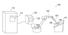
도 1은 예시적인 용접 시스템(100)을 도시한다. 예시적인 용접 시스템(100)은 전기 아크 토치(104)(예를 들어, 아크 용접 토치)를 작동시키는 로봇(102)을 포함한다. 그러나, 용접 시스템(100)은 로봇(102)을 포함할 필요는 없으며, 전기 아크 토치(104)가 사람에 의해 작동되는 수동 용접 시스템일 수 있다. 로봇(102)은 6축 관절형 산업용 로봇, 또는 예를 들어 궤도 파이프 용접기와 같은 다른 유형의 로봇일 수 있다.1 illustrates an
설명의 용이함을 위해, 시스템(100)의 양태는 아크 용접 토치를 사용하는 전기 아크 용접 시스템의 맥락에서 설명될 것이다. 그러나, 이러한 양태는 예를 들어, 적층 가공(additive manufacturing) 시스템과 같은 다른 유형의 아크 금속 증착 시스템에도 적용 가능하다는 것을 인식해야 한다. 또한, 시스템(100)은 특정 용접 공정으로 한정되지 않으며, 가스 텅스텐 아크 용접(GTAW), 가스 금속 아크 용접(GMAW), 용제-함유 아크 용접(FCAW), 스틱 용접(SMAW), 또는 잠수 아크 용접(SAW)과 같은 다양한 용접 공정을 수행하는데 사용될 수 있다.For ease of explanation, aspects of the
토치(104)는 소모성 와이어 전극과 같은 전극(106)을 포함할 수 있으며, 이를 통해 토치와 소재(110) 사이에 아크(108)가 발생되어 소재에 대한 용접 작업을 수행한다. 로봇(102)은 용접 동안에 토치(104)의 움직임을 제어하여 소재(110)에 대한 프로그래밍된 용접 작업을 수행한다. 프로그래밍된 용접 작업은 가변하는 지속시간의 복수의 용접 비드의 용접을 포함할 수 있다.The
시스템(100)은 전력 공급기(120)를 포함한다. 전력 공급기(120)는 아크(108)를 발생시키기 위해 토치(104)에 전력 출력을 제공한다. 전력 공급기(120)는 입력 전력(예를 들어, 설비 전력)을 소재(110)에 대한 용접 작업을 수행하기 위한 적절한 아크 파형(예를 들어, 용접 파형)으로 변환한다. 전력 공급기(120)는 원하는 아크 파형을 생성하기 위한 전자 회로(예를 들어, PWM 인버터, 초퍼 등)를 포함할 수 있다. 전력 공급기(120)는, 소재(110)에 대해 수행되는 작업의 다양한 파라미터(예를 들어, 전압, 전류, 와이어 이송 속도, AC 밸런스 등)를 조정하고 용접 동안에 용접 파형을 제어하기 위한 프로세서, 메모리 및 사용자 인터페이스(122)를 더 포함할 수 있다.
시스템(100)은 시스템에 의해 수행되는 용접의 품질을 결정할 수 있는 컴퓨팅 장치(112)를 더 포함한다. 컴퓨팅 장치(112)는 현재의 소재(110)에 대해 수행되는 용접의 품질에 관한 정보, 또는 이전에 용접된 소재에 대해 이루어진 용접의 품질에 관한 이력 정보를 사용자가 볼 수 있도록 하기 위한 사용자 인터페이스(114)를 갖는다. 또한, 컴퓨팅 장치(112)는 근거리 통신망 또는 광역 통신망을 통해, 원격 컴퓨팅 장치 또는 인간-기계 인터페이스, 경보 시스템, 이동 통신 장치 등과 같은 원격 장치(도시되지 않음)로 용접의 품질에 관한 정보를 출력하거나 전송할 수 있다.The
전력 공급기(120)는 용접 작업 동안에 용접 전압, 전류, 와이어 이송 속도 등과 같은 다양한 용접 파라미터를 모니터링하고, 용접 파라미터를 유선 또는 무선 통신 링크를 통해 컴퓨팅 장치(112)로 전송한다. 특정 실시형태에서, 컴퓨팅 장치(112)와의 용접 파라미터의 통신은 실시간으로 이루어질 수 있으므로, 조작자는 결함 있는 용접이 발생할 때 이에 대해 경보를 받을 수 있다. 컴퓨팅 장치(112)는 하나 이상의 용접 파라미터를 처리하여 용접 기호를 포착하고 용접 기호에 기초하여 용접 결함 조건을 결정한다. 또한, 컴퓨팅 장치(112)는 전력 공급기(120)로부터 용접 기호를 획득할 수 있다. 특정 실시형태에서, 컴퓨팅 장치(112)는 시스템(100)에 의해 이루어진 용접의 품질에 기초하여 전력 공급기(120)의 설정을 조정할 수 있다. 아래에서 설명되는 바와 같이, 컴퓨팅 장치(112)는 파라미터 값-기반 결함 분석 루틴(예를 들어, 적어도 하나의 용접 파라미터 값을 미리 결정된 한계값과 비교), 및/또는 기호 형상-기반 결함 분석 루틴(예를 들어, 용접 파라미터의 용접 기호의 형상을 기준 용접 기호 형상과 비교)을 수행할 수 있다.The
파라미터 값-기반 용접 품질 또는 결함 분석 루틴은 파라미터 및 결과적인 용접을 수용 가능 여부로서 정확히 특성화하기 위해, 문제가 되는 파라미터가 대체로 정상 상태에 도달하도록 요구할 수 있다. 매우 짧은 지속시간(예를 들어, 1초 미만)의 용접인 경우, 파라미터가 적절한 정상 상태에 도달하지 못할 수 있으므로, 파라미터 값-기반 용접 품질 분석 루틴은 용접을 수용 가능 또는 수용 불가능으로서 적절하게 특성화할 수 없거나 부정확할 수 있다.The parameter value-based weld quality or defect analysis routine may require that the problematic parameter generally reach a steady state in order to accurately characterize the parameter and the resulting weld as acceptable. In the case of welding with very short durations (eg less than 1 second), the parameter value-based welding quality analysis routine may properly characterize the weld as acceptable or unacceptable, since the parameters may not reach an adequate steady state. It may not be possible or may be incorrect.
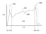
수용 가능한 용접을 나타낼 수 있지만, 파라미터 값-기반 용접 품질 분석 루틴에서 적합하지 않은 것이 되는 "불안정한" 용접 파라미터의 실시예가 도 2에 도시된다. 도 2는 용접 비드의 용접 동안 용접 전류의 예시적인 용접 기호(200)를 도시한다. 용접 전류 기호가 도 2에 도시되지만, 용접 기호(200)는 용접 기호 형상-기반 결함 분석 루틴에 사용될 수 있는 임의의 수의 다양한 용접 파라미터를 예시하기 위해 의도된다. 용접 기호(200)는 개시 루틴(202), 종료 루틴(204) 및 용접 부분(206)의 3개의 상태를 갖는다. 용접 전류는 용접 부분 동안에 증가하고 대체로 정상 상태에 도달하지 않는다는 것을 알 수 있다. 파라미터 값-기반 용접 품질 분석 루틴은 전형적으로 이러한 부분 동안 파라미터 값의 명확한 불안정성으로 인해 개시 루틴(202) 및 종료 루틴(204)을 폐기하고, 용접 부분(206)에 대해서만 값(예를 들어, 평균 전류, 중간값 전류 등)을 분석한다. 그러나, 용접 부분(206)의 지속시간이 짧고, 파라미터가 도시된 바와 같이 대체로 정상 상태에 도달하지 않는 경우, 미리 결정된 "정상" 한계값 또는 한계값들의 범위와의 파라미터의 편차를 정확하게 결정하는 것이 어려울 수 있다. 예를 들어, 수용 가능한 한계값들의 범위가 용접 부분(206)의 불안정성을 수용하도록 넓게 정해지는 경우, 수용 가능한 용접과 더불어, 넓은 범위 내에서 수용 불가능한 용접(예를 들어, 소재와 용접 전극의 원치 않는 단락으로 인해)이 포착될 가능성이 증가할 것이다. 반대로, 파라미터에 대한 수용 가능한 한계값들의 범위가 좁게 정해지는 경우, 용접 파라미터가 불안정하고 적절하게 특성화하기 어렵기 때문에, 몇몇 수용 가능한 용접들이 결함 있는 것으로 표시될 가능성이 증가할 것이다.An example of an "unstable" welding parameter, which may represent an acceptable weld, but which is not suitable in a parameter value-based welding quality analysis routine, is shown in FIG. 2. 2 shows an
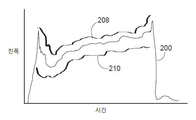
임의의 지속시간의 용접이지만, 특히 용접 부분(206)이 예를 들어 1초 미만인 짧은 지속시간의 용접인 경우, 수용 가능한 용접 및 용접 결함 조건은 기호 형상-기반 결함 분석 루틴을 사용함으로써 결정될 수 있다. 기호 형상-기반 결함 분석 루틴에서, 포착된 용접 기호와의 비교를 위해 컴퓨팅 장치(112)(도 1)에 의해 기준 용접 기호가 제공되며, 용접 기호의 형상은 기준 용접 기호 형상과 비교되어 둘 사이의 용접 기호 형상 차이를 결정한다. 용접 기호 형상 차이는 포착된 용접 기호의 형상과 기준 형상 사이의 차이의 정도이다. 그 다음, 용접 기호 형상 차이에 기초하여, 용접 결함 조건 또는 수용 가능한 용접이 결정된다.Any duration of welding, but especially if the
도 3에서, 예시적인 기준 용접 기호(208, 210)는 포착된 용접 기호(200)의 위 및 아래에 도시된다. 기준 용접 기호는 기호 형상-기반 결함 분석 루틴 동안 검색 및 사용을 위해 컴퓨팅 장치(112)(도 1)에 저장될 수 있다. 특정 실시형태에서, 컴퓨팅 장치(112)는 훈련 데이터로서, 알려진 양호한 용접 기호 및 알려진 결함 있는 용접 기호에 관한 기계 학습 기술 및 패턴 인식을 사용함으로써 기준 용접 기호를 학습할 수 있다.In FIG. 3, exemplary
컴퓨팅 장치(112)(도 1)는 포착된 용접 기호(200)의 형상을 하나 이상의 기준 용접 기호(208, 210)의 형상과 자동으로 비교하여 용접 기호 형상 차이를 결정한다. 기준 용접 기호(들)의 해당 부분과 정렬될 수 있도록, 용접 부분의 시작부 또는 종료부와 같은 용접 기호(200)에서의 핵심 특징부들을 식별하는 것이 필요할 수 있다. 정렬되면, 용접 기호(200)를 따르는 복수의 지점과 기준 용접 기호(들)가 비교되어 크기 차이, 기울기 차이, 2차 도함수들 간의 차이 등일 수 있는 복수의 형상 차이를 결정할 수 있다. 또한, 기준 용접 기호(들) 및 용접 기호(200)의 특정 부분들의 지속시간은 이들의 형상을 비교하는 단계의 일부로서 비교될 수 있다. 예를 들어, 개시 루틴의 종료시 전류 급강하의 지속시간이 비교될 수 있거나, 또는 용접 부분들의 지속시간이 비교될 수 있다. 또한, 용접 기호(200)에서 특정 특징부들이 식별되어, 예를 들어 해당 코드를 통해, 용접 기호를 정의하거나 기술하는데 사용될 수 있다. 코드는 기준 용접 기호(들)에 대한 유사한 코드와 비교되어 용접 기호 형상 차이를 결정할 수 있다. 또한, 용접 기호(200)의 형상이 형상 기준 용접 기호(들)와 적절히 매칭되는지 여부를 결정하는 것은 생체 인식 식별과 유사한 기술을 포함할 수 있으며, 매칭 스코어는 형상들 간의 유사점/차이점에 기초하여 생성된다. 매칭 스코어가 미리 결정된 임계값보다 더 높거나 또는 용접 기호 형상 차이가 미리 결정된 한계값보다 더 작은 경우, 용접은 합격인 것으로 간주될 것이다. 매칭 스코어가 임계값보다 더 작거나 또는 용접 기호 형상 차이가 미리 결정된 한계값을 초과하는 경우, 용접 결함 조건이 존재하는 것으로 결정된다. 또한, 용접 기호의 특정 부분들의 형상 특성들은 용접 기호의 다른 부분들보다 더 많이 가중될 수 있다. 예를 들어, 개시 루틴(202)(도 2) 동안의 피크값으로부터 용접 부분(206) 동안의 이의 최소값까지의 용접 전류의 기울기는 종료 루틴(204) 동안의 용접 기호의 형상보다 용접 품질을 결정하는 것과 관련하여 더 중요할 수 있다. 따라서, 종료 루틴 동안의 용접 기호(200)의 형상은 형상 비교에서 고려될 수 있지만(즉, 배제되지 않음), 용접 기호의 다른 더 유익한 부분들보다는 더 적게 가중될 수 있다. 당업자에 의해 인식되는 바와 같이, 용접 결함 조건의 존재를 결정할 때 다양한 방법의 형상 비교가 수행될 수 있다.Computing device 112 (FIG. 1) automatically compares the shape of captured
기호 형상-기반 결함 분석 루틴은 용접 비드의 용접 동안에 포착된 다수의 용접 파라미터(예를 들어, 용접 전압, 전류, 와이어 이송 속도 등)의 형상을 분석하는 단계를 포함할 수 있다. 포착된 용접 기호들과 기준 용접 기호들 사이의 형상 차이들은 전체적인 형상 차이를 결정하기 위해 함께 고려될 수 있으며, 그 다음 전체적인 형상 차이는 용접 결함 조건이 존재하는지 여부를 결정하는데 사용된다. 예를 들어, 전체적인 형상 차이를 결정하기 위해 형상 차이들을 추가하거나 평균할 수 있다. 특정 실시형태에서, 상이한 파라미터들의 포착된 용접 기호들은 해당 기준 용접 기호들과 개별적으로 비교된다. 대안적으로, 모니터링된 용접 파라미터들이 결합되어 다차원 용접 기호를 형성할 수 있으며, 다차원 용접 기호의 형상은 다차원 기준 용접 기호와 비교될 수 있다.The symbol shape-based defect analysis routine may include analyzing the shape of a number of welding parameters (eg, welding voltage, current, wire feed rate, etc.) captured during welding of the weld bead. The shape differences between the captured weld symbols and the reference weld symbols can be considered together to determine the overall shape difference, which is then used to determine whether a weld defect condition exists. For example, shape differences can be added or averaged to determine the overall shape difference. In a particular embodiment, the captured weld symbols of the different parameters are compared individually with the corresponding reference weld symbols. Alternatively, the monitored welding parameters can be combined to form a multidimensional weld symbol, and the shape of the multidimensional weld symbol can be compared with the multidimensional reference weld symbol.
기호 형상-기반 결함 분석 루틴은 용접 기호(200)를 상부 및/또는 하부 경계 기준 용접 기호와 비교하는 단계를 더 포함할 수 있다. 예시적인 상부(208) 및 하부(210) 경계 기준 용접 기호는 도 3에 도시된다. 상부(208) 및 하부(210) 경계 기준 용접 기호는 용접 기호와의 형상 비교를 위해, 포착된 용접 기호(200)와 유사한 형상 또는 프로파일을 가질 수 있다. 포착된 용접 기호(200)의 일부분이 경계 기준 용접 기호(208, 210) 중 하나를 초과하는 경우, 용접 결함이 존재하는 것으로 결정될 수 있다. 즉, 포착된 용접 기호(200)의 일부분이 상부(208) 및 하부(210) 경계에 의해 제공된 기호 윈도우의 외부에 있는 경우(예를 들어, 상부(208) 경계 위 또는 하부(210) 경계 아래), 용접 결함이 존재하는 것으로 결정된다. 용접 결함 조건의 결정은 포착된 용접 기호(200)와 기준 용접 기호(들)(208, 210) 사이의 용접 기호 형상 차이의 분석, 및 상부(208) 및 하부(210) 경계 중 하나 또는 모두와 용접 기호의 비교에 모두 기초할 수 있다. 형상 차이 또는 경계 테스트 중 어느 하나는 결함 있는 용접이 이루어졌다는 결정을 유도할 수 있다. 예를 들어, 상부(208) 및 하부(210) 경계 사이에 남아 있지만 기준 용접 기호(들)와 실질적으로 상이한 형상을 갖는 포착된 용접 기호는 결함 있는 것으로 간주될 수 있다. 유사하게, 기준 용접 기호(들)와 매우 유사하게 형상화되지만 상부(208) 또는 하부(210) 경계를 초과하는 포착된 용접 기호는 완전히 형상-기반 결함 분석에 합격하더라도, 결함 있는 것으로 간주될 수도 있다.The symbol shape-based defect analysis routine may further comprise comparing the
특정 실시형태에서, 용접 기호 형상-기반 용접 결함 분석 루틴은 용접 파라미터 값-기반 용접 결함 분석 루틴과 결합될 수 있다. 이러한 접근법은, 일부 용접은 파라미터 값-기반 결함 분석 루틴이 용접 품질을 정확하게 결정하기에 충분히 길고, 일부 용접은 파라미터 값-기반 결함 분석 루틴에 대해 너무 짧은, 가변하는 지속시간의 용접이 수행되는 경우 유용할 수 있다. 컴퓨팅 장치(112)(도 1)는 특정 용접 비드에 대한 용접 지속시간을 결정할 수 있다. 개시 루틴 및 종료 루틴은 흔히 파라미터 값-기반 결함 분석 루틴에서 폐기되기 때문에, 단지 용접 부분(206)(도 2)으로부터 또는 전체 용접 비드(예를 들어, 개시 루틴(202)으로부터 종료 루틴(204)까지의)로부터 용접 지속시간이 계산될 수 있다. 컴퓨팅 장치(112)는 저장된 결함 분석 지속시간 임계값(예를 들어, 2초, 1초, 500 ms 등)을 검색할 수 있다. 그 다음, 용접 지속시간은 결함 분석 지속시간 임계값과 비교되고, 비교 결과에 기초하여, 기호 형상-기반 용접 결함 분석 루틴 또는 파라미터 값-기반 용접 결함 분석 루틴이 선택된다. 예를 들어, 용접 지속시간(예를 들어, 용접 부분(206)의 지속시간)이 결함 분석 지속시간 임계값보다 더 작은 경우, 용접 기호 형상-기반 결함 분석이 수행된다. 용접 지속시간이 결함 분석 지속시간 임계값보다 더 큰 경우, 파라미터 값-기반 결함 분석이 수행된다. 파라미터 값-기반 결함 분석 루틴에서, 하나 이상의 용접 파라미터의 파라미터 값(예를 들어, 평균값, 중간값, 피크값, 최소값, RMS 값 등)은 결함 있는 용접이 이루어졌는지 여부를 결정하기 위해 미리 결정된 한계값들 또는 값들의 범위들(수용 가능한 파라미터 레벨들)과 비교될 수 있다. 또한, 파라미터 값-기반 결함 분석은 위에서 설명된 바와 같이, 용접 비드에 대한 전체적인 용접 스코어를 계산하는 단계를 포함할 수 있다. 또한, 용접 기호 형상-기반 결함 분석 및 파라미터 값-기반 결함 분석은 용접 지속시간이 파라미터 값-기반 결함 분석을 허용하는 경우에 결합될 수도 있다. 예를 들어, 평균 파라미터 값이 수용 가능한 값 범위 내에 있지만 용접 기호 형상이 기준 용접 기호와 매우 상이한 경우, 용접 결함 조건이 결정될 수 있다.In certain embodiments, a weld symbol shape-based weld defect analysis routine can be combined with a weld parameter value-based weld defect analysis routine. This approach allows some welds to be long enough for the parameter value-based defect analysis routine to accurately determine the weld quality, and some welds are too short for the parameter value-based defect analysis routine, if welding of varying duration is performed. Can be useful. Computing device 112 (FIG. 1) can determine a weld duration for a particular weld bead. Since the initiation routine and the termination routine are often discarded in the parameter value-based defect analysis routine, the
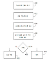
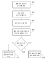
이제 도 4 및 도 5를 참조하면, 방법은 도시된 흐름도와 연계하여 설명된다. 설명되는 방법은 원하는 경우 컴퓨팅 장치(112) 또는 전력 공급기(120)(도 1)에 의해 수행될 수 있다. 도 4를 참조하면, 용접 품질을 결정하기 위한 방법의 흐름도가 도시된다. 400에서, 예를 들어 메모리 장치로부터 검색되는 바와 같은, 기준 용접 기호가 제공된다. 402에서, 용접 파라미터의 용접 기호가 포착된다. 404에서, 기준 용접 기호의 형상은 포착된 용접 기호의 형상과 비교되고, 기준 용접 기호와 포착된 용접 기호의 형상 사이의 하나 이상의 형상 차이가 결정된다. 406에서, 포착된 용접 기호는 상부 및 하부 경계와 비교된다. 408에서, 결함 용접이 발생했는지 여부에 대한 결정이 이루어진다. 결정은 기준 용접 기호와 포착된 용접 기호의 형상 사이의 하나 이상의 형상 차이에 기초할 수 있거나/기초할 수 있고, 포착된 용접 기호를 상부 및 하부 경계와 비교하는 것에 기초할 수 있다. 용접 결함 조건이 발생하지 않은 경우, 용접 작업은 정상적으로 계속될 수 있다(410). 용접 결함 조건이 발생한 경우, 결함 루틴이 개시될 수 있다(412). 결함 루틴은 용접 비드를 결함이 있는 것으로 표시하는 단계, 경보를 발생시키는 단계, 미리 결정된 사람 또는 장치로 메시지를 전송하는 단계, 용접 공정을 중지시키는 단계 등을 포함할 수 있다.Referring now to FIGS. 4 and 5, the method is described in conjunction with the depicted flowchart. The described method may be performed by computing
용접 품질을 결정하기 위한 추가적인 방법은 도 5의 흐름도에 도시된다. 500에서, 예를 들어 메모리 장치로부터 검색되는 바와 같은, 결함 분석 지속시간 임계값이 제공된다. 502에서, 용접 비드의 용접 기호가 포착된다. 504에서, 용접 비드의 용접 지속시간이 결정된다. 506에서, 용접 비드의 용접 지속시간은 결함 분석 지속시간 임계값과 비교된다. 508에서, 용접 지속시간이 결함 분석 지속시간 임계값보다 더 큰지 여부에 대한 결정이 이루어진다. 용접 비드에 대한 용접 지속시간이 결함 분석 지속시간 임계값보다 더 큰 경우, 적어도 하나의 용접 파라미터 값을 미리 결정된 한계값과 비교하는 단계를 포함할 수 있는 파라미터 값-기반 결함 분석 루틴이 수행된다(510). 용접 비드에 대한 용접 지속시간이 결함 분석 지속시간 임계값보다 더 작은 경우, 용접 기호의 형상을 기준 용접 기호 형상과 비교하는 단계를 포함할 수 있는 기호 형상-기반 결함 분석 루틴이 수행된다(512).An additional method for determining weld quality is shown in the flowchart of FIG. 5. At 500 a defect analysis duration threshold is provided, for example as retrieved from a memory device. At 502, a weld symbol of a weld bead is captured. At 504, a weld duration of a weld bead is determined. At 506, the weld duration of the weld bead is compared with a defect analysis duration threshold. At 508, a determination is made whether the weld duration is greater than the defect analysis duration threshold. If the weld duration for the weld bead is greater than the defect analysis duration threshold, a parameter value-based defect analysis routine is performed that may include comparing at least one weld parameter value with a predetermined threshold value ( 510). If the weld duration for the weld bead is less than the defect analysis duration threshold, a symbol shape-based defect analysis routine is performed that may include comparing the shape of the weld symbol with a reference weld symbol shape (512). .
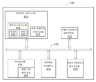
도 6은 컴퓨팅 장치(112)(도 1)의 예시적인 실시형태를 도시한다. 컴퓨팅 장치(112)는 버스 서브시스템(812)을 통해 다수의 주변 장치와 통신하는 적어도 하나의 프로세서(814)를 포함한다. 이러한 주변 장치는 예를 들어, 메모리 서브시스템(828) 및 파일 저장장치 서브시스템(826)을 포함하는 저장장치 서브시스템(824), 사용자 인터페이스 입력 장치(822), 사용자 인터페이스 출력 장치(820), 및 네트워크 인터페이스 서브시스템(816)을 포함할 수 있다. 입력 및 출력 장치는 컴퓨팅 장치(112)와의 사용자 상호 작용을 가능하게 한다. 네트워크 인터페이스 서브시스템(816)은 외부 네트워크로의 인터페이스를 제공하고, 다른 컴퓨터 시스템 또는 프로그래밍 가능한 장치의 해당 인터페이스 장치에 결합될 수 있다.6 illustrates an example embodiment of computing device 112 (FIG. 1).
사용자 인터페이스 입력 장치(822)는 마우스, 트랙볼, 터치패드 또는 그래픽스 태블릿과 같은 포인팅 장치, 키보드, 스캐너, 디스플레이 내로 통합된 터치 스크린, 음성 인식 시스템, 마이크로폰과 같은 오디오 입력 장치, 및/또는 다른 유형의 입력 장치를 포함할 수 있다. 일반적으로, "입력 장치"라는 용어의 사용은 컴퓨팅 장치(112)로 또는 통신 네트워크 상으로 정보를 입력하는 모든 가능한 유형의 장치 및 방식을 포함하는 것으로 의도된다.The user
사용자 인터페이스 출력 장치(820)는 디스플레이 서브시스템, 프린터, 팩스 기계, 또는 오디오 출력 장치와 같은 비-시각적 디스플레이를 포함할 수 있다. 디스플레이 서브시스템은 음극선관(CRT), 액정 디스플레이(LCD)와 같은 평판 장치, 프로젝션 장치, 또는 가시적 이미지를 생성하기 위한 몇몇 다른 장치를 포함할 수 있다. 또한, 디스플레이 서브시스템은 예를 들어 오디오 출력 장치를 통해, 비-시각적 디스플레이를 제공할 수 있다. 일반적으로, "출력 장치"라는 용어의 사용은 컴퓨팅 장치(112)로부터 사용자로 또는 다른 기계나 컴퓨터 시스템으로 정보를 출력하는 모든 가능한 유형의 장치 및 방식을 포함하는 것으로 의도된다.The user
저장장치 서브시스템(824)은 본원에서 설명된 동작들 중 일부 또는 전부의 기능을 제공하는 프로그래밍 및 데이터 구성체를 저장하는 비-일시적인 컴퓨터 판독 가능한 저장 매체를 제공한다. 예를 들어, 저장장치 서브시스템(824)은 컴퓨팅 장치(112)가 위에서 설명된 용접 품질 분석 루틴을 실행할 수 있도록 하기 위한 프로그래밍 명령을 포함할 수 있다.Storage subsystem 824 provides a non-transitory computer readable storage medium that stores programming and data constructs that provide the functionality of some or all of the operations described herein. For example, storage subsystem 824 may include programming instructions to enable
프로그래밍 명령을 갖는 펌웨어 또는 소프트웨어 모듈은 일반적으로 프로세서(814) 단독으로 또는 다른 프로세서와 결합하여 실행된다. 저장장치 서브시스템(824)에서 사용되는 메모리 서브시스템(828)은 프로그램 실행 동안 명령 및 데이터의 저장을 위한 주 랜덤 액세스 메모리(RAM)(830), 및 고정 명령이 저장되는 판독 전용 메모리(ROM)(832)를 포함하는 다수의 메모리를 포함할 수 있다. 파일 저장장치 서브시스템(826)은 프로그램 및 데이터 파일을 위한 영구적인 저장을 제공할 수 있으며, 하드 디스크 드라이브, 연동된 착탈식 매체와 함께 플로피 디스크 드라이브, CD-ROM 드라이브, 광 드라이브, 또는 착탈식 매체 카트리지를 포함할 수 있다. 특정 실시형태들의 기능을 구현하는 모듈들은 프로세서(들)(814)에 의해 액세스 가능한 다른 기계들에서 또는 저장장치 서브시스템(824)에서 파일 저장장치 서브시스템(826)에 의해 저장될 수 있다.Firmware or software modules having programming instructions are generally executed by the
버스 서브시스템(812)은 컴퓨팅 장치(112)의 다양한 구성 요소들 및 서브시스템들이 의도된 바와 같이 서로 통신하게 하기 위한 메커니즘을 제공한다. 버스 서브시스템(812)은 단일 버스로서 개략적으로 도시되지만, 버스 서브시스템의 대안적인 실시형태는 다수의 버스를 사용할 수 있다.
메모리 서브시스템(824)에 저장되고 프로세서(814)에 의해 실행되는 프로그래밍 명령은 프로세서로 하여금 용접 기호 분석 엔진(834)을 구현하거나 포함하도록 할 수 있다. 용접 기호 분석 엔진(834)은 위에서 설명된 용접 품질을 결정하는 다양한 방법을 수행할 수 있다.Programming instructions stored in the memory subsystem 824 and executed by the
특정 실시형태에서, 컴퓨팅 장치(112)는 제어 명령을 로봇(102)에 제공하여 용접 동안에 이의 움직임을 제어하는 로봇 제어기의 일부일 수 있다(도 1).In a particular embodiment,
본 개시물은 예시로서, 본 개시물에 포함된 교시의 타당한 범위를 벗어나지 않고 세부사항을 추가, 변형 또는 제거함으로써 다양한 변경이 이루어질 수 있음은 명백해야 한다. 따라서, 본 발명은 이하의 청구범위에서 불가피하게 그렇게 한정되는 정도까지를 제외하고는 본 개시물의 특정 세부사항들로 한정되지 않는다.It is to be apparent that the present disclosure is illustrative, and that various changes may be made by adding, modifying, or removing details without departing from the proper scope of the teachings contained in the present disclosure. Accordingly, the invention is not limited to the specific details of the disclosure except to the extent that it is unavoidably so limited in the following claims.
Claims (20)
제1 형상을 갖는 기준 용접 기호를 제공하는 단계;
용접 파라미터의 용접 기호를 포착하는 단계로서, 상기 용접 파라미터의 상기 용접 기호는 제2 형상을 갖는, 단계;
상기 제1 형상을 상기 제2 형상과 자동으로 비교하여 상기 제1 형상과 상기 제2 형상 사이의 용접 기호 형상 차이를 결정하는 단계; 및
상기 용접 기호 형상 차이에 기초하여 용접 결함 조건을 결정하는 단계를 포함하는,
용접 품질을 결정하는 방법.As a method of determining the welding quality,
Providing a reference weld symbol having a first shape;
Capturing a weld symbol of a weld parameter, the weld symbol of the weld parameter having a second shape;
Automatically comparing the first shape with the second shape to determine a weld symbol shape difference between the first shape and the second shape; And
Determining a weld defect condition based on the weld symbol shape difference;
How to determine the weld quality.
상기 용접 파라미터는 복수의 용접 파라미터를 포함하며, 상기 제2 형상은 각각의 상기 복수의 용접 파라미터에 기초하는, 방법.The method of claim 1,
The welding parameter comprises a plurality of welding parameters, and wherein the second shape is based on each of the plurality of welding parameters.
상기 제1 형상을 상기 제2 형상과 자동으로 비교하여 용접 기호 형상 차이를 결정하는 단계는 상기 제1 형상과 상기 제2 형상 사이의 복수의 형상 차이를 결정하는 단계를 포함하는, 방법.The method of claim 1,
Automatically comparing the first shape with the second shape to determine a weld symbol shape difference comprises determining a plurality of shape differences between the first shape and the second shape.
상기 용접 파라미터의 상기 용접 기호를 상부 경계 및 하부 경계 중 적어도 하나와 비교하는 단계를 더 포함하며, 상기 용접 결함 조건의 결정은 상기 용접 기호 형상 차이, 및 상기 용접 파라미터의 상기 용접 기호를 상기 상부 경계 및 상기 하부 경계 중 적어도 하나와 비교하는 상기 단계의 결과에 모두 기초하는, 방법.The method of claim 1,
Comparing the weld symbol of the weld parameter to at least one of an upper boundary and a lower boundary, wherein the determination of the weld defect condition comprises the weld symbol shape difference and the weld symbol of the weld parameter to the upper boundary And all based on the results of said step of comparing with at least one of said lower boundaries.
상기 용접 파라미터의 상기 용접 기호의 일부분이 상기 상부 경계 및 상기 하부 경계 중 적어도 하나를 초과하는 경우, 상기 용접 결함 조건이 존재하는 것으로 결정되는, 방법.The method of claim 4, wherein
If a portion of the weld symbol of the weld parameter exceeds at least one of the upper boundary and the lower boundary, it is determined that the weld defect condition exists.
상기 용접 파라미터의 상기 용접 기호를 상부 경계 및 하부 경계 모두와 비교하는 단계를 더 포함하며, 상기 용접 결함 조건의 결정은 상기 용접 기호 형상 차이, 및 상기 용접 파라미터의 상기 용접 기호를 상기 상부 경계 및 상기 하부 경계 모두와 비교하는 상기 단계의 결과에 모두 기초하는, 방법.The method of claim 1,
Comparing the weld symbol of the weld parameter to both an upper boundary and a lower boundary, wherein the determination of the weld defect condition comprises the weld symbol shape difference, and the weld symbol of the weld parameter to the upper boundary and the All based on the results of said step comparing all of the lower boundaries.
상기 용접 기호 형상 차이가 미리 결정된 한계값을 초과하는 경우 또는 상기 용접 파라미터의 상기 용접 기호의 일부분이 상기 상부 경계 또는 상기 하부 경계를 초과하는 경우, 상기 용접 결함 조건이 존재하는 것으로 결정되는, 방법.The method of claim 6,
If the weld symbol shape difference exceeds a predetermined threshold value or if a portion of the weld symbol of the weld parameter exceeds the upper boundary or the lower boundary, it is determined that the weld defect condition exists.
용접 비드를 용접하는 동안에 용접 전력 공급기에 의해 상기 용접 파라미터를 모니터링하는 단계; 및
상기 모니터링된 용접 파라미터를 컴퓨팅 장치로 전송하는 단계를 더 포함하며,
상기 컴퓨팅 장치는 상기 제1 형상을 상기 제2 형상과 자동으로 비교하여 상기 제1 형상과 상기 제2 형상 사이의 상기 용접 기호 형상 차이를 결정하는 단계, 및 상기 용접 기호 형상 차이에 기초하여 상기 용접 결함 조건을 결정하는 단계를 수행하는, 방법.The method of claim 1,
Monitoring the welding parameters by a welding power supply while welding a weld bead; And
Sending the monitored welding parameters to a computing device,
The computing device automatically comparing the first shape with the second shape to determine the weld symbol shape difference between the first shape and the second shape, and the welding based on the weld symbol shape difference Determining a fault condition.
상기 컴퓨터 실행 가능한 명령은 실행될 때,
제1 형상을 갖는 기준 용접 기호를 검색하며;
제2 형상을 갖는 용접 비드 파라미터의 용접 기호를 획득하고;
상기 제1 형상을 상기 제2 형상과 비교하여 상기 제1 형상과 상기 제2 형상 사이의 용접 기호 형상 차이를 결정하며; 그리고
상기 용접 기호 형상 차이에 기초하여 용접 결함 조건을 결정하도록 프로세서를 구성하는,
컴퓨터 실행 가능한 명령이 저장된 비-일시적인 컴퓨터 판독 가능한 저장 매체.A non-transitory computer readable storage medium having computer executable instructions stored thereon,
When the computer executable instruction is executed,
Retrieve a reference weld symbol having a first shape;
Obtain a weld symbol of a weld bead parameter having a second shape;
Compare the first shape with the second shape to determine a weld symbol shape difference between the first shape and the second shape; And
Configure a processor to determine a weld defect condition based on the weld symbol shape difference;
A non-transitory computer readable storage medium that stores computer executable instructions.
상기 용접 비드 파라미터는 복수의 용접 파라미터를 포함하며, 상기 제2 형상은 각각의 상기 복수의 용접 파라미터에 기초하는, 비-일시적인 컴퓨터 판독 가능한 저장 매체.The method of claim 9,
And the weld bead parameter comprises a plurality of weld parameters, and wherein the second shape is based on each of the plurality of weld parameters.
용접 비드의 용접 지속시간을 결정하고;
상기 용접 비드의 상기 용접 지속시간을 결함 분석 지속시간 임계값과 비교하며; 그리고
상기 용접 비드의 상기 용접 지속시간을 상기 결함 분석 지속시간 임계값과 비교한 결과에 기초하여, 용접 기호 형상-기반 용접 결함 분석 루틴 및 용접 파라미터 값-기반 용접 결함 분석 루틴 중 하나를 선택하도록 상기 프로세서를 구성하는 명령을 추가로 저장하는, 비-일시적인 컴퓨터 판독 가능한 저장 매체.The method of claim 9,
Determine a welding duration of the weld bead;
Compare the weld duration of the weld bead with a defect analysis duration threshold; And
The processor to select one of a weld symbol shape-based weld defect analysis routine and a weld parameter value-based weld defect analysis routine based on a result of comparing the weld duration of the weld bead with the defect analysis duration threshold. And non-transitory computer readable storage medium.
상기 용접 비드 파라미터의 상기 용접 기호를 상부 경계 및 하부 경계 중 적어도 하나와 비교하며; 그리고
상기 용접 기호 형상 차이, 및 상기 용접 비드 파라미터의 상기 용접 기호를 상기 상부 경계 및 상기 하부 경계 중 적어도 하나와 비교한 결과에 모두 기초하여, 상기 용접 결함 조건을 결정하도록 상기 프로세서를 구성하는 명령을 추가로 저장하는, 비-일시적인 컴퓨터 판독 가능한 저장 매체.The method of claim 9,
Compare the weld symbol of the weld bead parameter with at least one of an upper boundary and a lower boundary; And
Add a command to configure the processor to determine the weld defect condition based on both the weld symbol shape difference and a result of comparing the weld symbol of the weld bead parameter to at least one of the upper boundary and the lower boundary; And non-transitory computer readable storage medium.
상기 용접 비드 파라미터의 상기 용접 기호의 일부분이 상기 상부 경계 및 상기 하부 경계 중 적어도 하나를 초과하는 경우, 상기 용접 결함 조건이 존재하는 것으로 결정되는, 비-일시적인 컴퓨터 판독 가능한 저장 매체.The method of claim 12,
And if a portion of the weld symbol of the weld bead parameter exceeds at least one of the upper boundary and the lower boundary, it is determined that the weld failure condition exists.
상기 용접 비드 파라미터의 상기 용접 기호를 상부 경계 및 하부 경계 모두와 비교하며; 그리고
상기 용접 기호 형상 차이, 및 상기 용접 비드 파라미터의 상기 용접 기호를 상기 상부 경계 및 상기 하부 경계 모두와 비교한 결과에 모두 기초하여, 상기 용접 결함 조건을 결정하도록 상기 프로세서를 구성하는 명령을 추가로 저장하고,
상기 용접 기호 형상 차이가 미리 결정된 한계값을 초과하는 경우 또는 상기 용접 비드 파라미터의 상기 용접 기호의 일부분이 상기 상부 경계 또는 상기 하부 경계를 초과하는 경우, 상기 용접 결함 조건이 존재하는 것으로 결정되는, 비-일시적인 컴퓨터 판독 가능한 저장 매체.The method of claim 9,
Compare the weld symbol of the weld bead parameter with both an upper boundary and a lower boundary; And
Further storing instructions to configure the processor to determine the weld defect condition based on both the weld symbol shape difference and the result of comparing the weld symbol of the weld bead parameter to both the upper boundary and the lower boundary. and,
If the weld symbol shape difference exceeds a predetermined threshold value or if a portion of the weld symbol of the weld bead parameter exceeds the upper boundary or the lower boundary, it is determined that the weld defect condition exists. Temporary computer readable storage medium.
결함 분석 지속기간 임계값을 제공하는 단계;
용접 비드의 용접 기호를 획득하는 단계로서, 상기 용접 기호는 형상을 갖는, 단계;
상기 용접 비드의 용접 지속시간을 결정하는 단계;
상기 용접 비드의 상기 용접 지속시간을 상기 결함 분석 지속시간 임계값과 비교하는 단계;
상기 용접 비드에 대한 상기 용접 지속시간이 상기 결함 분석 지속시간 임계값보다 더 큰 경우, 적어도 하나의 용접 파라미터 값을 미리 결정된 한계값과 비교하는 단계를 포함하는 파라미터 값-기반 결함 분석 루틴을 수행하는 단계; 및
상기 용접 비드에 대한 상기 용접 지속시간이 상기 결함 분석 지속시간 임계값보다 더 작은 경우, 상기 용접 기호의 상기 형상을 기준 용접 기호 형상과 비교하는 단계를 포함하는 기호 형상-기반 결함 분석 루틴을 수행하는 단계를 포함하는,
용접 품질을 결정하는 방법.As a method of determining the welding quality,
Providing a defect analysis duration threshold;
Obtaining a weld symbol of a weld bead, the weld symbol having a shape;
Determining a welding duration of the weld bead;
Comparing the weld duration of the weld bead with the defect analysis duration threshold;
If the welding duration for the weld bead is greater than the defect analysis duration threshold, performing a parameter value-based defect analysis routine comprising comparing at least one welding parameter value with a predetermined threshold value. step; And
Performing a symbol shape-based defect analysis routine comprising comparing the shape of the weld symbol with a reference weld symbol shape when the weld duration for the weld bead is less than the defect analysis duration threshold. Comprising the steps,
How to determine the weld quality.
상기 용접 비드를 용접하는 동안에 용접 전력 공급기에 의해 용접 파라미터를 모니터링하는 단계; 및
상기 모니터링된 용접 파라미터를 컴퓨팅 장치로 전송하는 단계를 더 포함하며,
상기 컴퓨팅 장치는 상기 용접 비드의 상기 용접 지속시간을 상기 결함 분석 지속시간 임계값과 비교하는 단계를 수행하고, 상기 용접 비드에 대한 상기 기호 형상-기반 결함 분석 루틴 및 상기 파라미터 값-기반 결함 분석 루틴 중 하나를 수행하는, 방법.The method of claim 15,
Monitoring a welding parameter by a welding power supply while welding the welding bead; And
Sending the monitored welding parameters to a computing device,
The computing device performs the step of comparing the weld duration of the weld bead with the defect analysis duration threshold, wherein the symbol shape-based defect analysis routine and the parameter value-based defect analysis routine for the weld bead To do one of the methods.
상기 기호 형상-기반 결함 분석 루틴은,
상기 용접 기호의 상기 형상과 상기 기준 용접 기호 형상 사이의 용접 기호 형상 차이를 결정하는 단계; 및
상기 용접 기호 형상 차이에 기초하여 용접 결함 조건을 결정하는 단계를 더 포함하는, 방법.The method of claim 15,
The symbol shape-based defect analysis routine is
Determining a weld symbol shape difference between the shape of the weld symbol and the reference weld symbol shape; And
Determining a weld defect condition based on the weld symbol shape difference.
상기 기호 형상-기반 결함 분석 루틴은,
상기 용접 기호를 상부 경계 및 하부 경계 중 적어도 하나와 비교하는 단계; 및
상기 용접 기호 형상 차이, 및 상기 용접 기호를 상기 상부 경계 및 상기 하부 경계 중 적어도 하나와 비교한 결과에 모두 기초하여, 용접 결함 조건을 결정하는 단계를 더 포함하는, 방법.The method of claim 17,
The symbol shape-based defect analysis routine is
Comparing the weld symbol with at least one of an upper boundary and a lower boundary; And
And determining a weld defect condition based on both the weld symbol shape difference and a result of comparing the weld symbol with at least one of the upper boundary and the lower boundary.
상기 용접 기호의 일부분이 상기 상부 경계 및 상기 하부 경계 중 적어도 하나를 초과하는 경우, 상기 용접 결함 조건이 존재하는 것으로 결정되는, 방법.The method of claim 18,
If a portion of the weld symbol exceeds at least one of the upper boundary and the lower boundary, it is determined that the weld defect condition exists.
상기 기호 형상-기반 결함 분석 루틴은,
상기 용접 기호를 상부 경계 및 하부 경계 모두와 비교하는 단계; 및
상기 용접 기호 형상 차이, 및 상기 용접 기호를 상기 상부 경계 및 상기 하부 경계 모두와 비교한 결과에 모두 기초하여, 용접 결함 조건을 결정하는 단계를 더 포함하며,
상기 용접 기호 형상 차이가 미리 정의된 한계값을 초과하는 경우 또는 상기 용접 기호의 일부분이 상기 상부 경계 또는 상기 하부 경계를 초과하는 경우, 상기 용접 결함 조건이 존재하는 것으로 결정되는, 방법.The method of claim 17,
The symbol shape-based defect analysis routine is
Comparing the weld symbol with both an upper boundary and a lower boundary; And
Determining a weld defect condition based on both the weld symbol shape difference and a result of comparing the weld symbol with both the upper boundary and the lower boundary;
If the weld symbol shape difference exceeds a predefined threshold value or if a portion of the weld symbol exceeds the upper boundary or the lower boundary, it is determined that the weld defect condition exists.
Applications Claiming Priority (2)
| Application Number | Priority Date | Filing Date | Title |
|---|---|---|---|
| US15/926,216 US11267066B2 (en) | 2018-03-20 | 2018-03-20 | Weld signature analysis for weld quality determination |
| US15/926,216 | 2018-03-20 |
Publications (1)
| Publication Number | Publication Date |
|---|---|
| KR20190110436A true KR20190110436A (en) | 2019-09-30 |
Family
ID=65903986
Family Applications (1)
| Application Number | Title | Priority Date | Filing Date |
|---|---|---|---|
| KR1020190025145A KR20190110436A (en) | 2018-03-20 | 2019-03-05 | Weld signature analysis for weld quality determination |
Country Status (5)
| Country | Link |
|---|---|
| US (1) | US11267066B2 (en) |
| EP (1) | EP3542943B1 (en) |
| JP (1) | JP7339746B2 (en) |
| KR (1) | KR20190110436A (en) |
| CN (1) | CN110303267A (en) |
Families Citing this family (5)
| Publication number | Priority date | Publication date | Assignee | Title |
|---|---|---|---|---|
| US11633813B2 (en) * | 2019-11-22 | 2023-04-25 | GM Global Technology Operations LLC | Real-time weld quality analysis systems and methods |
| JP7303163B2 (en) | 2020-07-20 | 2023-07-04 | 株式会社神戸製鋼所 | Defect Occurrence Prediction Method and Defect Occurrence Prediction Apparatus |
| EP4019177A1 (en) * | 2020-12-22 | 2022-06-29 | FRONIUS INTERNATIONAL GmbH | Method and device for assessing the quality of a processing process |
| CN114012210B (en) * | 2021-12-06 | 2022-12-09 | 上海交通大学 | Deposition quality judgment system and method in electric arc additive process |
| CN114167189B (en) * | 2021-12-08 | 2023-11-03 | 华中科技大学鄂州工业技术研究院 | Welding defect detection method, electronic equipment and storage medium |
Family Cites Families (23)
| Publication number | Priority date | Publication date | Assignee | Title |
|---|---|---|---|---|
| US5306893A (en) | 1992-07-31 | 1994-04-26 | The United States Of America As Represented By The Secretary Of The Navy | Weld acoustic monitor |
| JPH06341966A (en) | 1993-04-08 | 1994-12-13 | Hitachi Zosen Corp | Welding state observing method in ultrasonic welding device |
| US5406044A (en) | 1994-04-20 | 1995-04-11 | Eaton Corporation | Displacement monitoring system for stud welding |
| US5674415A (en) | 1996-01-22 | 1997-10-07 | The University Of Chicago | Method and apparatus for real time weld monitoring |
| US6329635B1 (en) | 1998-10-30 | 2001-12-11 | The University Of Chicago | Methods for weld monitoring and laser heat treatment monitoring |
| US6236017B1 (en) * | 1999-07-01 | 2001-05-22 | Bechtel Bwxt Idaho, Llc | Method and apparatus for assessing weld quality |
| JP3472237B2 (en) | 2000-05-18 | 2003-12-02 | 株式会社小松製作所 | Plasma arc spot welding machine |
| US6441342B1 (en) * | 2000-11-20 | 2002-08-27 | Lincoln Global, Inc. | Monitor for electric arc welder |
| US6583386B1 (en) | 2000-12-14 | 2003-06-24 | Impact Engineering, Inc. | Method and system for weld monitoring and tracking |
| DE10136992A1 (en) | 2001-07-23 | 2003-02-06 | Emhart Llc Newark | Short duration arc welding involves comparing unsmoothed measurement curve with tolerance curve generated from smoothed measurement curve to detect high frequency faults |
| US7132617B2 (en) * | 2002-02-20 | 2006-11-07 | Daimlerchrysler Corporation | Method and system for assessing quality of spot welds |
| GB0301090D0 (en) * | 2003-01-17 | 2003-02-19 | British Nuclear Fuels Plc | Welding quality control |
| JP4486407B2 (en) | 2004-05-06 | 2010-06-23 | 株式会社ダイヘン | Resistance welding control method |
| US8963045B2 (en) * | 2006-09-19 | 2015-02-24 | Lincoln Global, Inc. | Non-linear adaptive control system and method for welding |
| US20140042137A1 (en) * | 2006-12-20 | 2014-02-13 | Lincoln Global, Inc. | System and method of exporting or using welding sequencer data for external systems |
| GB0709420D0 (en) | 2007-05-17 | 2007-06-27 | Rolls Royce Plc | Machining process monitor |
| US20090200282A1 (en) | 2008-02-08 | 2009-08-13 | Gm Global Technology Operations, Inc. | Weld signature monitoring method and apparatus |
| JP5558771B2 (en) | 2009-10-07 | 2014-07-23 | 東邦車輛株式会社 | Axle manufacturing method and axle manufacturing system |
| US9468988B2 (en) | 2009-11-13 | 2016-10-18 | Lincoln Global, Inc. | Systems, methods, and apparatuses for monitoring weld quality |
| US8742280B2 (en) * | 2010-01-07 | 2014-06-03 | Illinois Tool Works Inc. | Systems and methods for statistically analyzing welding operations |
| DE102011077754A1 (en) | 2011-06-17 | 2012-12-20 | Otto Bihler Handels-Beteiligungs-Gmbh | Device useful for welding first metal element with second metal element by resistance welding, comprises welding electrode arrangement, electric welding current supply and arrangement for monitoring welding process |
| US10661373B2 (en) | 2015-09-14 | 2020-05-26 | Illinois Tool Works Inc. | Systems and methods for providing weld quality confidence |
| US11027352B2 (en) | 2015-09-14 | 2021-06-08 | Illinois Tool Works Inc. | Systems and methods for analyzing weld signatures using pulse forensic features |
-
2018
- 2018-03-20 US US15/926,216 patent/US11267066B2/en active Active
-
2019
- 2019-03-01 CN CN201910158371.5A patent/CN110303267A/en active Pending
- 2019-03-05 KR KR1020190025145A patent/KR20190110436A/en unknown
- 2019-03-13 JP JP2019045384A patent/JP7339746B2/en active Active
- 2019-03-19 EP EP19163800.6A patent/EP3542943B1/en active Active
Also Published As
| Publication number | Publication date |
|---|---|
| EP3542943B1 (en) | 2023-04-26 |
| JP7339746B2 (en) | 2023-09-06 |
| CN110303267A (en) | 2019-10-08 |
| EP3542943A1 (en) | 2019-09-25 |
| US20190291200A1 (en) | 2019-09-26 |
| US11267066B2 (en) | 2022-03-08 |
| JP2019162666A (en) | 2019-09-26 |
Similar Documents
| Publication | Publication Date | Title |
|---|---|---|
| US11267066B2 (en) | Weld signature analysis for weld quality determination | |
| CN109834367B (en) | System and method for torch oscillation | |
| US10857611B2 (en) | Systems and methods for statistically analyzing welding operations | |
| US10363628B2 (en) | Automatic and semi-automatic welding systems and methods | |
| US11833624B2 (en) | Method for determining Arc consistency in pulsed gas metal Arc welding systems | |
| JP6359189B2 (en) | System, method and apparatus for monitoring welding quality | |
| JPWO2020129618A1 (en) | Welding system and method of welding workpieces using it | |
| MX2014012464A (en) | System and method for monitoring weld quality. | |
| CN110385512B (en) | Welding monitoring and control system and welding monitoring and control method | |
| WO2018168448A1 (en) | Welding state determination system and welding state determination method | |
| JP7482665B2 (en) | Real-time resistance monitoring of arc welding circuits | |
| CN114025904A (en) | Repair welding inspection device and repair welding inspection method | |
| CA3066730A1 (en) | System and method for conditioning an output of a welding type power supply | |
| CN105290595A (en) | Welding controls and methods for monitoring the cleaning of a welding tool and a device for operating a welding tool | |
| KR101584421B1 (en) | Monitoring system for arc welding | |
| US11897060B2 (en) | Systems and methods for welding torch weaving | |
| JP2004122180A (en) | Apparatus for selecting welding parameter and apparatus for inspecting weld | |
| JP7306898B2 (en) | Controllers, programs, and robot control systems | |
| CN115302044A (en) | System and method for torch weaving | |
| JP2023030990A (en) | Welding support method, welding support system, and program | |
| JP2023004319A (en) | Welding parameter adjusting method, welding parameter setting device, and welding system | |
| CN114178735A (en) | Angle steel grating plate welding supervision method, system and device and storage medium |