EP3542943B1 - Method of and non transitory computer readable storage medium for determining weld quality by realising a weld signature analysis - Google Patents
Method of and non transitory computer readable storage medium for determining weld quality by realising a weld signature analysis Download PDFInfo
- Publication number
- EP3542943B1 EP3542943B1 EP19163800.6A EP19163800A EP3542943B1 EP 3542943 B1 EP3542943 B1 EP 3542943B1 EP 19163800 A EP19163800 A EP 19163800A EP 3542943 B1 EP3542943 B1 EP 3542943B1
- Authority
- EP
- European Patent Office
- Prior art keywords
- weld
- shape
- signature
- welding
- parameter
- Prior art date
- Legal status (The legal status is an assumption and is not a legal conclusion. Google has not performed a legal analysis and makes no representation as to the accuracy of the status listed.)
- Active
Links
- 238000000034 method Methods 0.000 title claims description 30
- 238000003860 storage Methods 0.000 title claims description 21
- 238000003466 welding Methods 0.000 claims description 122
- 239000011324 bead Substances 0.000 claims description 34
- 238000012544 monitoring process Methods 0.000 claims 2
- 230000015654 memory Effects 0.000 description 8
- 238000010586 diagram Methods 0.000 description 6
- 238000010891 electric arc Methods 0.000 description 5
- 238000004891 communication Methods 0.000 description 3
- 238000013459 approach Methods 0.000 description 2
- 230000002093 peripheral effect Effects 0.000 description 2
- 230000000007 visual effect Effects 0.000 description 2
- 239000000654 additive Substances 0.000 description 1
- 230000000996 additive effect Effects 0.000 description 1
- 230000001419 dependent effect Effects 0.000 description 1
- 230000003993 interaction Effects 0.000 description 1
- 239000004973 liquid crystal related substance Substances 0.000 description 1
- 238000010801 machine learning Methods 0.000 description 1
- 238000004519 manufacturing process Methods 0.000 description 1
- 229910052751 metal Inorganic materials 0.000 description 1
- 239000002184 metal Substances 0.000 description 1
- 238000001465 metallisation Methods 0.000 description 1
- 238000010295 mobile communication Methods 0.000 description 1
- 230000003287 optical effect Effects 0.000 description 1
- 238000003909 pattern recognition Methods 0.000 description 1
- 230000002085 persistent effect Effects 0.000 description 1
- 238000007778 shielded metal arc welding Methods 0.000 description 1
- 238000012360 testing method Methods 0.000 description 1
- 238000012549 training Methods 0.000 description 1
- WFKWXMTUELFFGS-UHFFFAOYSA-N tungsten Chemical compound [W] WFKWXMTUELFFGS-UHFFFAOYSA-N 0.000 description 1
- 229910052721 tungsten Inorganic materials 0.000 description 1
- 239000010937 tungsten Substances 0.000 description 1
Images


Classifications
-
- B—PERFORMING OPERATIONS; TRANSPORTING
- B23—MACHINE TOOLS; METAL-WORKING NOT OTHERWISE PROVIDED FOR
- B23K—SOLDERING OR UNSOLDERING; WELDING; CLADDING OR PLATING BY SOLDERING OR WELDING; CUTTING BY APPLYING HEAT LOCALLY, e.g. FLAME CUTTING; WORKING BY LASER BEAM
- B23K31/00—Processes relevant to this subclass, specially adapted for particular articles or purposes, but not covered by only one of the preceding main groups
- B23K31/12—Processes relevant to this subclass, specially adapted for particular articles or purposes, but not covered by only one of the preceding main groups relating to investigating the properties, e.g. the weldability, of materials
- B23K31/125—Weld quality monitoring
-
- B—PERFORMING OPERATIONS; TRANSPORTING
- B23—MACHINE TOOLS; METAL-WORKING NOT OTHERWISE PROVIDED FOR
- B23K—SOLDERING OR UNSOLDERING; WELDING; CLADDING OR PLATING BY SOLDERING OR WELDING; CUTTING BY APPLYING HEAT LOCALLY, e.g. FLAME CUTTING; WORKING BY LASER BEAM
- B23K31/00—Processes relevant to this subclass, specially adapted for particular articles or purposes, but not covered by only one of the preceding main groups
- B23K31/02—Processes relevant to this subclass, specially adapted for particular articles or purposes, but not covered by only one of the preceding main groups relating to soldering or welding
-
- B—PERFORMING OPERATIONS; TRANSPORTING
- B23—MACHINE TOOLS; METAL-WORKING NOT OTHERWISE PROVIDED FOR
- B23K—SOLDERING OR UNSOLDERING; WELDING; CLADDING OR PLATING BY SOLDERING OR WELDING; CUTTING BY APPLYING HEAT LOCALLY, e.g. FLAME CUTTING; WORKING BY LASER BEAM
- B23K31/00—Processes relevant to this subclass, specially adapted for particular articles or purposes, but not covered by only one of the preceding main groups
- B23K31/12—Processes relevant to this subclass, specially adapted for particular articles or purposes, but not covered by only one of the preceding main groups relating to investigating the properties, e.g. the weldability, of materials
-
- B—PERFORMING OPERATIONS; TRANSPORTING
- B23—MACHINE TOOLS; METAL-WORKING NOT OTHERWISE PROVIDED FOR
- B23K—SOLDERING OR UNSOLDERING; WELDING; CLADDING OR PLATING BY SOLDERING OR WELDING; CUTTING BY APPLYING HEAT LOCALLY, e.g. FLAME CUTTING; WORKING BY LASER BEAM
- B23K9/00—Arc welding or cutting
- B23K9/095—Monitoring or automatic control of welding parameters
- B23K9/0953—Monitoring or automatic control of welding parameters using computing means
-
- B—PERFORMING OPERATIONS; TRANSPORTING
- B23—MACHINE TOOLS; METAL-WORKING NOT OTHERWISE PROVIDED FOR
- B23K—SOLDERING OR UNSOLDERING; WELDING; CLADDING OR PLATING BY SOLDERING OR WELDING; CUTTING BY APPLYING HEAT LOCALLY, e.g. FLAME CUTTING; WORKING BY LASER BEAM
- B23K9/00—Arc welding or cutting
- B23K9/095—Monitoring or automatic control of welding parameters
- B23K9/0956—Monitoring or automatic control of welding parameters using sensing means, e.g. optical
-
- B—PERFORMING OPERATIONS; TRANSPORTING
- B23—MACHINE TOOLS; METAL-WORKING NOT OTHERWISE PROVIDED FOR
- B23K—SOLDERING OR UNSOLDERING; WELDING; CLADDING OR PLATING BY SOLDERING OR WELDING; CUTTING BY APPLYING HEAT LOCALLY, e.g. FLAME CUTTING; WORKING BY LASER BEAM
- B23K9/00—Arc welding or cutting
- B23K9/10—Other electric circuits therefor; Protective circuits; Remote controls
- B23K9/1006—Power supply
- B23K9/1043—Power supply characterised by the electric circuit
- B23K9/1056—Power supply characterised by the electric circuit by using digital means
- B23K9/1062—Power supply characterised by the electric circuit by using digital means with computing means
-
- B—PERFORMING OPERATIONS; TRANSPORTING
- B23—MACHINE TOOLS; METAL-WORKING NOT OTHERWISE PROVIDED FOR
- B23K—SOLDERING OR UNSOLDERING; WELDING; CLADDING OR PLATING BY SOLDERING OR WELDING; CUTTING BY APPLYING HEAT LOCALLY, e.g. FLAME CUTTING; WORKING BY LASER BEAM
- B23K9/00—Arc welding or cutting
- B23K9/16—Arc welding or cutting making use of shielding gas
-
- B—PERFORMING OPERATIONS; TRANSPORTING
- B23—MACHINE TOOLS; METAL-WORKING NOT OTHERWISE PROVIDED FOR
- B23K—SOLDERING OR UNSOLDERING; WELDING; CLADDING OR PLATING BY SOLDERING OR WELDING; CUTTING BY APPLYING HEAT LOCALLY, e.g. FLAME CUTTING; WORKING BY LASER BEAM
- B23K9/00—Arc welding or cutting
- B23K9/32—Accessories
Definitions
- the invention is related to a method of determining weld quality according to the preamble of claim 1 (see for example JP 2001 321949 A ), and to a non-transitory, computer-readable storage medium according to claim 11.
- the present disclosure relates to determining the quality of welds, and in particular to a weld signature shape-based approach to determining the quality of welds.
- Welding parameters such as voltage and current are monitored during a welding operation, and can be used to determine the quality of a resulting weld. The value of one or more parameters can be compared to acceptable levels for the parameter, to determine whether or not the weld passes or fails. More sophisticated techniques for determining weld quality involve measuring multiple weld parameters and calculating multiple quality parameters in order to generate an overall weld score, which quantifies the overall quality of the weld. Such a technique is disclosed in U.S. Patent No. 9,468,988 to Daniel .
- the parameter may never reach an appropriate steady state and, thus, automated methods of weld quality determination may be inaccurate or unable to properly characterize the weld. It would be desirable to automatically determine the weld quality of such short duration welds in a manner that is largely unaffected by the instability in the monitored welding parameters.
- a method of determining weld quality according to the present invention is defined in claim 1.
- a non-transitory, computer-readable storage medium according to the present invention is defined in claim 11.
- Preferred embodiments are defined in the dependent claims 2-10 and 12-15.
- Embodiments of the present disclosure relate to systems and methods for determining the quality of welds.
- the embodiments will now be described with reference to the drawings, wherein like reference numerals are used to refer to like elements throughout. It is to be appreciated that the various drawings are not necessarily drawn to scale from one figure to another nor inside a given figure, and in particular that the size of the components are arbitrarily drawn for facilitating the understanding of the drawings. In the following description, for purposes of explanation, numerous specific details are set forth in order to provide a thorough understanding of the present invention. It may be evident, however, that the present invention can be practiced without these specific details.
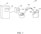
- FIG 1 shows an example welding system 100.
- the example welding system 100 includes a robot 102 that operates an electric arc torch 104 (e.g., an arc welding torch).
- the welding system 100 need not include a robot 102 and could be a manual welding system in which the electric arc torch 104 is operated by a person.
- the robot 102 can be a sixaxis articulating industrial robot, or another type of robot, such as an orbital pipe welder for example.
- system 100 will be discussed in the context of an electric arc welding system employing an arc welding torch. However, it is to be appreciated that such aspects are also applicable to other types of arc metal deposition systems, such as an additive manufacturing system for example. Moreover, the system 100 is not limited to a particular welding process and could be used to perform various welding processes, such as gas tungsten arc welding (GTAW), gas metal arc welding (GMAW), flux-cored arc welding (FCAW), stick welding (SMAW), or submerged arc welding (SAW).
- GTAW gas tungsten arc welding
- GMAW gas metal arc welding
- FCAW flux-cored arc welding
- SAW submerged arc welding
- the torch 104 can include an electrode 106, such as a consumable wire electrode, through which an arc 108 is generated between the torch and a workpiece 110 to perform a welding operation on the workpiece.
- the robot 102 controls the movements of the torch 104 during welding to perform a programmed welding operation on the workpiece 110.
- the programmed welding operation can include the welding of a plurality of weld beads of varying duration.
- the system 100 includes a power supply 120.
- the power supply 120 provides an electrical power output to the torch 104 to generate the arc 108.
- the power supply 120 converts input electrical power (e.g., utility power) into a suitable arc waveform (e.g., a welding waveform) for performing a welding operation on the workpiece 110.
- the power supply 120 can include electronic circuitry (e.g., PWM inverters, choppers, etc.) for generating a desired arc waveform.
- the power supply 120 can further include a processor, memory, and a user interface 122 for adjusting various parameters of the operation performed on the workpiece 110 (e.g., voltage, current, wire feed speed, AC balance, etc.) and for controlling the welding waveform during welding.
- the system 100 further includes a computing device 112 that can determine the quality of welds performed by the system.
- the computing device 112 has a user interface 114 for allowing a user to view information regarding the quality of welds performed on a current workpiece 110 or historical information regarding the quality of welds made on previouslywelded workpieces.
- the computing device 112 can also output or transmit information regarding the quality of welds to a remote device (not shown), such as a remote computing device or human-machine interface, an alarm system, a mobile communication device, etc., via a local or wide area network.
- the power supply 120 monitors various welding parameters, such as welding voltage, current, wire feed speed, etc., during a welding operation and transmits the welding parameters to the computing device 112 via a wired or wireless communication link.
- the communication of welding parameters to the computing device 112 can occur in real-time, so that an operator can be alerted to faulty welds as they occur.
- the computing device 112 processes one or more of the welding parameters to capture a weld signature and determine a weld fault condition based on the weld signature.
- the computing device 112 may also obtain the weld signature from the power supply 120.
- the computing device 112 can make adjustments to settings of the power supply 120 based on the quality of welds made by the system 110.
- the computing device 112 can perform either a parameter value-based fault analysis routine (e.g., comparing at least one welding parameter value to a predetermined limit value) and/or a signature shape-based fault analysis routine (e.g., comparing the shape of a weld signature of a welding parameter to a reference weld signature shape).
- a parameter value-based fault analysis routine e.g., comparing at least one welding parameter value to a predetermined limit value
- a signature shape-based fault analysis routine e.g., comparing the shape of a weld signature of a welding parameter to a reference weld signature shape.
- Parameter value-based weld quality or fault analysis routines may require the parameter at issue to reach a generally steady state in order to accurately characterize the parameter, and the resulting weld, as acceptable or not.
- the parameter may never reach an appropriate steady state and, thus, parameter value-based weld quality analysis routines may be inaccurate or unable to properly characterize the weld as acceptable or unacceptable.
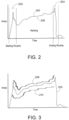
- FIG. 2 depicts an example weld signature 200 of welding current during welding of a weld bead.
- a weld current signature is shown in Fig. 2
- the weld signature 200 is intended to illustrate of any number of various welding parameters that could be used in a weld signature shape-based fault analysis routine.
- the weld signature 200 has three states: a starting routine 202, and ending routine 204 and a welding portion 206. It can be seen that the welding current increases during the welding portion and, according to the present invention, does not reach a generally steady state.
- a parameter value-based weld quality analysis routine would typically discard the starting routine 202 and the ending routine 204 due to the clear instability in the parameter's value during these portions, and analyze the value (e.g., average current, median current, etc.) of only the welding portion 206.
- the duration of the welding portion 206 is short, and the parameter does not reach a generally steady state as shown, it is difficult to accurately determine a deviation of the parameter from a predetermined "normal" limit value or range of limit values.
- the range of acceptable limit values is made large to accommodate the instability of the welding portion 206, then there will be an increased chance that unacceptable welds (e.g., due to unwanted shorting of the welding electrode to the workpiece) are captured within the large range, in addition to acceptable welds. Conversely, if the range of acceptable limit values for the parameter is made small, then there will be an increased chance that some acceptable welds will be flagged as faulty, because the welding parameter is unstable and difficult to properly characterize.
- acceptable welds and weld fault conditions can be determined by using a signature shape-based fault analysis routine.
- a signature shape-based fault analysis routine a reference weld signature is provided by the computing device 112 ( Fig. 1 ) for comparison to the captured weld signature, and the shape of the weld signature is compared to the reference weld signature shape to determine a weld signature shape difference between the two.
- the weld signature shape difference is a degree of difference between the reference shape and the shape of the captured weld signature.
- a weld fault condition or an acceptable weld is then determined based on the weld signature shape difference.
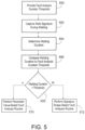
- Example reference weld signatures 208, 210 are shown in Fig. 3 above and below a captured weld signature 200.
- Reference weld signatures can be stored in the computing device 112 ( Fig. 1 ) for retrieval and use during a signature shape-based fault analysis routine.
- the computing device 112 can learn reference weld signatures by employing machine learning techniques and pattern recognition with respect to known good and known faulty weld signatures as training data.
- the computing device 112 ( Fig. 1 ) automatically compares the shape of the captured weld signature 200 to the shape of one or more reference weld signatures 208, 210 to determine the weld signature shape difference. It may be necessary to identify key features in the weld signature 200, such as the beginning or end of the welding portion, so that it can be aligned with corresponding portions of the reference weld signature(s). Once aligned, a plurality of points along the weld signature 200 and reference weld signature(s) can be compared to determine a plurality of shape differences, which could be magnitude differences, slope differences, differences between the second derivatives, and the like.
- the duration of certain portions of the weld signature 200 and reference weld signature(s) can also be compared as part of comparing their shapes. For example, the duration of the current dips at the end of the starting routines can be compared, or the duration of the welding portions can be compared.
- Particular features can also be identified in the weld signature 200 and used to define or describe the weld signature, such by way of a corresponding code. The code can be compared to a similar code for the reference weld signature(s) to determine the weld signature shape difference.
- determining whether or not the shape of the weld signature 200 adequately matches the shape reference weld signature(s) can involve techniques similar to biometric identification, in which a matching score is generated based on the similarities/differences between the shapes.
- a matching score is generated based on the similarities/differences between the shapes.
- the matching score is higher than a predetermined threshold or the weld signature shape difference is less than a predetermined limit, the weld will be treated as passing.
- the matching score is less than the threshold or the weld signature shape difference exceeds a predetermined limit, a weld fault condition is determined to exist.
- the shape characteristics of particular portions of the weld signature can be weighed more heavily than other portions of the weld signature. For example, the slope of the welding current from a peak during the starting routine 202 ( Fig.
- the shape of the weld signature 200 during the ending routine could be considered (i.e., not excluded) in the shape comparison, but weighed less heavily than other, more informative portions of the welding signature.
- shape comparison can be performed in determining the existence of a weld fault condition, as would be appreciated by one of ordinary skill in the art.
- the signature shape-based fault analysis routine can include analyzing the shape of multiple welding parameters captured during the welding of a weld bead (e.g., welding voltage, current, wire feed speed, etc.)
- the shape differences between the captured weld signatures and reference weld signatures can be considered together to determine an overall shape difference, which then is used to determine whether or not a weld fault condition exists.
- the shape differences can be added or averaged to determine an overall shape difference.
- the captured weld signatures of different parameters are compared individually to corresponding reference weld signatures.
- the monitored welding parameters can be combined to form a multi-dimensional weld signature, and the shape of the multi-dimensional weld signature can be compared to a multi-dimensional reference weld signature.
- the signature shape-based fault analysis routine can further include comparing the weld signature 200 to upper and/or lower boundary reference weld signatures.
- Example upper 208 and lower 210 boundary reference weld signatures are shown in Fig. 3 .
- the upper 208 and lower 210 boundary reference weld signatures can have a shape or profile similar to the captured weld signature 200 for shape comparison with the weld signature. If a portion of the captured weld signature 200 exceeds one of the boundary reference weld signatures 208, 210, a weld fault can be determined to exist.
- a weld fault is determined to exist. Determination of the weld fault condition can be based on both of an analysis of the weld signature shape difference between the captured weld signature 200 and the reference weld signature(s) 208, 210 and the comparison of the weld signature to one or both of the upper 208 and lower 210 boundaries. Either of the shape difference or boundary tests can lead to the determination that a faulty weld has been made.
- a captured weld signature that remains between the upper 208 and lower 210 boundaries but has a substantially different shape from the reference weld signature(s) could be considered to be faulty.
- a captured weld signature that is shaped very similarly to the reference weld signature(s) but exceeds either the upper 208 or lower 210 boundaries could also be considered to be faulty, even if it would pass a purely shape-based fault analysis.
- weld signature shape-based weld fault analysis routines can be combined with weld parameter value-based weld fault analysis routines. Such an approach is useful when welds of varying duration are performed on a workpiece, with some welds being sufficiently long for a parameter value-based fault analysis routine to accurately determine weld quality, and some welds being too short for a parameter value-based fault analysis routine.
- the computing device 112 determines a welding duration for a particular weld bead. The welding duration is calculated from the entire weld bead (e.g., from starting routine 202 to the ending routine 204) or from just the welding portion 206 ( Fig.
- the computing device 112 retrieves a stored fault analysis duration threshold (e.g., 2 seconds, 1 second, 500 ms, etc.). The welding duration is then compared to the fault analysis duration threshold, and either the signature shape-based weld fault analysis routine and the parameter value-based weld fault analysis routine is selected, based on the result of the comparison. According to the present invention, when the welding duration (e.g., the duration of the welding portion 206) is less than the fault analysis duration threshold, the weld signature shape-based fault analysis is performed. And, according to the present invention, when the welding duration is greater than the fault analysis duration threshold, the parameter value-based fault analysis is performed.
- a stored fault analysis duration threshold e.g., 2 seconds, 1 second, 500 ms, etc.
- a parameter value (e.g., average value, median value, peak value, minimum value, RMS value, etc.) of one or more welding parameters can be compared to predetermined limit values or ranges of values (acceptable parameter levels) to determine whether or not a faulty weld has been made.
- Parameter value-based fault analysis can also involve calculating an overall weld score for the weld bead, as discussed above.
- Weld signature shape-based fault analysis and parameter value-based fault analysis can also be combined when the welding duration allows for parameter value-based fault analysis. For example, if an average parameter value is within an acceptable range of values, but the weld signature shape deviates excessively from a reference weld signature, a weld fault condition can be determined.
- a reference weld signature is provided, such as retrieved from a memory device.
- a weld signature of a welding parameter is captured.
- the shape of the reference weld signature is compared to the shape of the captured weld signature, and one or more shape differences between the reference weld signature and the shape of the captured weld signature is determined.
- the captured weld signature is compared to upper and lower boundaries.
- a methodology for determining weld quality is illustrated in the flow diagram of Fig. 5 .
- a fault analysis duration threshold is provided, such as retrieved from a memory device.
- a weld signature of a weld bead is captured.
- a welding duration of the weld bead is determined.
- the welding duration of the weld bead is compared to the fault analysis duration threshold.
- a determination is made as to whether or not the welding duration is greater than the fault analysis duration threshold.
- a parameter value-based fault analysis routine is performed, which can include comparing at least one welding parameter value to a predetermined limit value 510.
- a signature shape-based fault analysis routine is performed, which can include comparing the shape of the weld signature to a reference weld signature shape 512.
- FIG. 6 illustrates an example embodiment of computing device 112 ( Fig. 1 ).
- the computing device 112 includes at least one processor 814 which communicates with a number of peripheral devices via bus subsystem 812.
- peripheral devices may include a storage subsystem 824, including, for example, a memory subsystem 828 and a file storage subsystem 826, user interface input devices 822, user interface output devices 820, and a network interface subsystem 816.
- the input and output devices allow user interaction with the computing device 112.
- Network interface subsystem 816 provides an interface to outside networks and can be coupled to corresponding interface devices in other computer systems or programmable devices.
- User interface input devices 822 may include a keyboard, pointing devices such as a mouse, trackball, touchpad, or graphics tablet, a scanner, a touchscreen incorporated into the display, audio input devices such as voice recognition systems, microphones, and/or other types of input devices.
- pointing devices such as a mouse, trackball, touchpad, or graphics tablet
- audio input devices such as voice recognition systems, microphones, and/or other types of input devices.
- use of the term "input device” is intended to include all possible types of devices and ways to input information into the computing device 112 or onto a communication network.
- User interface output devices 820 may include a display subsystem, a printer, a fax machine, or non-visual displays such as audio output devices.
- the display subsystem may include a cathode ray tube (CRT), a flat-panel device such as a liquid crystal display (LCD), a projection device, or some other mechanism for creating a visible image.
- the display subsystem may also provide non-visual display such as via audio output devices.
- output device is intended to include all possible types of devices and ways to output information from the computing device 112 to the user or to another machine or computer system.
- Storage subsystem 824 provides a non-transitory, computer-readable storage medium that stores programming and data constructs that provide the functionality of some or all of the operations described herein.
- the storage subsystem 824 may include programming instructions to allow the computing device 112 to execute the weld quality analysis routines described above.
- Memory subsystem 828 used in the storage subsystem 824 can include a number of memories including a main random access memory (RAM) 830 for storage of instructions and data during program execution and a read only memory (ROM) 832 in which fixed instructions are stored.
- a file storage subsystem 826 can provide persistent storage for program and data files, and may include a hard disk drive, a floppy disk drive along with associated removable media, a CD-ROM drive, an optical drive, or removable media cartridges.
- the modules implementing the functionality of certain embodiments may be stored by file storage subsystem 826 in the storage subsystem 824, or in other machines accessible by the processor(s) 814.
- Bus subsystem 812 provides a mechanism for letting the various components and subsystems of the computing device 112 communicate with each other as intended. Although bus subsystem 812 is shown schematically as a single bus, alternative embodiments of the bus subsystem may use multiple buses.
- the programming instructions stored in the memory subsystem 824 and executed by the processor 814 can cause the processor to implement or include a weld signature analysis engine 834.
- the weld signature analysis engine 834 can perform the various methods of determining weld quality discussed above.
- the computing device 112 can be part of a robot controller that provides control instructions to the robot 102 to control its movements during welding ( Fig. 1 ).
- REFERENCE NUMERALS 100 welding system 502 step capture weld signal 102 robot 504 step determine welding duration 104 electric arc torch 506 step compare welding duration 106 electrode 508 step determine threshold 108 arc 510 step perform fault analysis routine 110 workpiece 512 step perform fault analysis routine 112 computing device 812 bus subsystem 114 user interface 814 processor 120 power supply 816 network interface subsystem 122 user interface 820 output device 200 weld signature 822 input device 202 starting routine 824 storage subsystem 204 ending routine 826 file storage subsystem 206 welding portion 828 memory subsystem 208 weld signature 830 random access memory 210 weld signature 832 read only memory 400 step provide weld signature 834 analysis engine 402 step capture weld signature 404 step determine shape difference 406 step compare weld signature 408 step determine fault 410 step continue operation 412 step initiate fault routine 500 step
Description
- The invention is related to a method of determining weld quality according to the preamble of claim 1 (see for example
JP 2001 321949 A - The present disclosure relates to determining the quality of welds, and in particular to a weld signature shape-based approach to determining the quality of welds.
- Welding parameters such as voltage and current are monitored during a welding operation, and can be used to determine the quality of a resulting weld. The value of one or more parameters can be compared to acceptable levels for the parameter, to determine whether or not the weld passes or fails. More sophisticated techniques for determining weld quality involve measuring multiple weld parameters and calculating multiple quality parameters in order to generate an overall weld score, which quantifies the overall quality of the weld. Such a technique is disclosed in
U.S. Patent No. 9,468,988 to Daniel - A problem with parameter value-based weld quality or fault analysis routines, such as those discussed above, is that they may require a welding parameter to reach a generally steady state in order to accurately characterize the parameter as acceptable or not. For welds of very short duration (e.g., less than 1 second), the parameter may never reach an appropriate steady state and, thus, automated methods of weld quality determination may be inaccurate or unable to properly characterize the weld. It would be desirable to automatically determine the weld quality of such short duration welds in a manner that is largely unaffected by the instability in the monitored welding parameters.
- In order to improve the weld quality, a method of determining weld quality according to the present invention is defined in claim 1. A non-transitory, computer-readable storage medium according to the present invention is defined in claim 11. Preferred embodiments are defined in the dependent claims 2-10 and 12-15.
- The following summary presents a simplified summary in order to provide a basic understanding of some aspects of the devices, systems and/or methods discussed herein.
-
-
FIG. 1 is an example electric arc generation system; -
FIG. 2 is a waveform; -
FIG. 3 shows multiple waveforms; -
FIG. 4 is a flow diagram; -
FIG. 5 is a flow diagram; and -
FIG. 6 is a schematic diagram of an example computing device. - Embodiments of the present disclosure relate to systems and methods for determining the quality of welds. The embodiments will now be described with reference to the drawings, wherein like reference numerals are used to refer to like elements throughout. It is to be appreciated that the various drawings are not necessarily drawn to scale from one figure to another nor inside a given figure, and in particular that the size of the components are arbitrarily drawn for facilitating the understanding of the drawings. In the following description, for purposes of explanation, numerous specific details are set forth in order to provide a thorough understanding of the present invention. It may be evident, however, that the present invention can be practiced without these specific details.
-
Figure 1 shows anexample welding system 100. Theexample welding system 100 includes arobot 102 that operates an electric arc torch 104 (e.g., an arc welding torch). However, thewelding system 100 need not include arobot 102 and could be a manual welding system in which theelectric arc torch 104 is operated by a person. Therobot 102 can be a sixaxis articulating industrial robot, or another type of robot, such as an orbital pipe welder for example. - For ease of explanation, aspects of the
system 100 will be discussed in the context of an electric arc welding system employing an arc welding torch. However, it is to be appreciated that such aspects are also applicable to other types of arc metal deposition systems, such as an additive manufacturing system for example. Moreover, thesystem 100 is not limited to a particular welding process and could be used to perform various welding processes, such as gas tungsten arc welding (GTAW), gas metal arc welding (GMAW), flux-cored arc welding (FCAW), stick welding (SMAW), or submerged arc welding (SAW). - The
torch 104 can include anelectrode 106, such as a consumable wire electrode, through which anarc 108 is generated between the torch and aworkpiece 110 to perform a welding operation on the workpiece. Therobot 102 controls the movements of thetorch 104 during welding to perform a programmed welding operation on theworkpiece 110. The programmed welding operation can include the welding of a plurality of weld beads of varying duration. - The
system 100 includes apower supply 120. Thepower supply 120 provides an electrical power output to thetorch 104 to generate thearc 108. Thepower supply 120 converts input electrical power (e.g., utility power) into a suitable arc waveform (e.g., a welding waveform) for performing a welding operation on theworkpiece 110. Thepower supply 120 can include electronic circuitry (e.g., PWM inverters, choppers, etc.) for generating a desired arc waveform. Thepower supply 120 can further include a processor, memory, and auser interface 122 for adjusting various parameters of the operation performed on the workpiece 110 (e.g., voltage, current, wire feed speed, AC balance, etc.) and for controlling the welding waveform during welding. - The
system 100 further includes acomputing device 112 that can determine the quality of welds performed by the system. Thecomputing device 112 has auser interface 114 for allowing a user to view information regarding the quality of welds performed on acurrent workpiece 110 or historical information regarding the quality of welds made on previouslywelded workpieces. Thecomputing device 112 can also output or transmit information regarding the quality of welds to a remote device (not shown), such as a remote computing device or human-machine interface, an alarm system, a mobile communication device, etc., via a local or wide area network. - The
power supply 120 monitors various welding parameters, such as welding voltage, current, wire feed speed, etc., during a welding operation and transmits the welding parameters to thecomputing device 112 via a wired or wireless communication link. In certain embodiments, the communication of welding parameters to thecomputing device 112 can occur in real-time, so that an operator can be alerted to faulty welds as they occur. Thecomputing device 112 processes one or more of the welding parameters to capture a weld signature and determine a weld fault condition based on the weld signature. Thecomputing device 112 may also obtain the weld signature from thepower supply 120. In certain embodiments, thecomputing device 112 can make adjustments to settings of thepower supply 120 based on the quality of welds made by thesystem 110. As will be explained below, thecomputing device 112 can perform either a parameter value-based fault analysis routine (e.g., comparing at least one welding parameter value to a predetermined limit value) and/or a signature shape-based fault analysis routine (e.g., comparing the shape of a weld signature of a welding parameter to a reference weld signature shape). - Parameter value-based weld quality or fault analysis routines may require the parameter at issue to reach a generally steady state in order to accurately characterize the parameter, and the resulting weld, as acceptable or not. For welds of very short duration (e.g., less than 1 second), the parameter may never reach an appropriate steady state and, thus, parameter value-based weld quality analysis routines may be inaccurate or unable to properly characterize the weld as acceptable or unacceptable.
- An example of an "unstable" welding parameter that may indicate an acceptable weld, but would not be appropriate for a parameter value-based weld quality analysis routine, is shown in
Fig. 2. Figure 2 depicts anexample weld signature 200 of welding current during welding of a weld bead. Although a weld current signature is shown inFig. 2 , theweld signature 200 is intended to illustrate of any number of various welding parameters that could be used in a weld signature shape-based fault analysis routine. According to the present invention, theweld signature 200 has three states: astarting routine 202, and endingroutine 204 and awelding portion 206. It can be seen that the welding current increases during the welding portion and, according to the present invention, does not reach a generally steady state. A parameter value-based weld quality analysis routine would typically discard thestarting routine 202 and the endingroutine 204 due to the clear instability in the parameter's value during these portions, and analyze the value (e.g., average current, median current, etc.) of only thewelding portion 206. However, as the duration of thewelding portion 206 is short, and the parameter does not reach a generally steady state as shown, it is difficult to accurately determine a deviation of the parameter from a predetermined "normal" limit value or range of limit values. For example, if the range of acceptable limit values is made large to accommodate the instability of thewelding portion 206, then there will be an increased chance that unacceptable welds (e.g., due to unwanted shorting of the welding electrode to the workpiece) are captured within the large range, in addition to acceptable welds. Conversely, if the range of acceptable limit values for the parameter is made small, then there will be an increased chance that some acceptable welds will be flagged as faulty, because the welding parameter is unstable and difficult to properly characterize. - For welds of any duration, but in particular welds of short duration when the
welding portion 206 is less than 1 second for example, acceptable welds and weld fault conditions can be determined by using a signature shape-based fault analysis routine. In a signature shape-based fault analysis routine, a reference weld signature is provided by the computing device 112 (Fig. 1 ) for comparison to the captured weld signature, and the shape of the weld signature is compared to the reference weld signature shape to determine a weld signature shape difference between the two. The weld signature shape difference is a degree of difference between the reference shape and the shape of the captured weld signature. A weld fault condition or an acceptable weld is then determined based on the weld signature shape difference. - Example
reference weld signatures Fig. 3 above and below a capturedweld signature 200. Reference weld signatures can be stored in the computing device 112 (Fig. 1 ) for retrieval and use during a signature shape-based fault analysis routine. In certain embodiments, thecomputing device 112 can learn reference weld signatures by employing machine learning techniques and pattern recognition with respect to known good and known faulty weld signatures as training data. - The computing device 112 (
Fig. 1 ) automatically compares the shape of the capturedweld signature 200 to the shape of one or morereference weld signatures weld signature 200, such as the beginning or end of the welding portion, so that it can be aligned with corresponding portions of the reference weld signature(s). Once aligned, a plurality of points along theweld signature 200 and reference weld signature(s) can be compared to determine a plurality of shape differences, which could be magnitude differences, slope differences, differences between the second derivatives, and the like. The duration of certain portions of theweld signature 200 and reference weld signature(s) can also be compared as part of comparing their shapes. For example, the duration of the current dips at the end of the starting routines can be compared, or the duration of the welding portions can be compared. Particular features can also be identified in theweld signature 200 and used to define or describe the weld signature, such by way of a corresponding code. The code can be compared to a similar code for the reference weld signature(s) to determine the weld signature shape difference. Further, determining whether or not the shape of theweld signature 200 adequately matches the shape reference weld signature(s) can involve techniques similar to biometric identification, in which a matching score is generated based on the similarities/differences between the shapes. When the matching score is higher than a predetermined threshold or the weld signature shape difference is less than a predetermined limit, the weld will be treated as passing. When the matching score is less than the threshold or the weld signature shape difference exceeds a predetermined limit, a weld fault condition is determined to exist. Also, the shape characteristics of particular portions of the weld signature can be weighed more heavily than other portions of the weld signature. For example, the slope of the welding current from a peak during the starting routine 202 (Fig. 2 ) to its minimum value during thewelding portion 206 could be more important with respect to determining weld quality than the shape of the weld signature during theending routine 204. Thus, the shape of theweld signature 200 during the ending routine could be considered (i.e., not excluded) in the shape comparison, but weighed less heavily than other, more informative portions of the welding signature. Various methods of shape comparison can be performed in determining the existence of a weld fault condition, as would be appreciated by one of ordinary skill in the art. - The signature shape-based fault analysis routine can include analyzing the shape of multiple welding parameters captured during the welding of a weld bead (e.g., welding voltage, current, wire feed speed, etc.) The shape differences between the captured weld signatures and reference weld signatures can be considered together to determine an overall shape difference, which then is used to determine whether or not a weld fault condition exists. For example, the shape differences can be added or averaged to determine an overall shape difference. In certain embodiments, the captured weld signatures of different parameters are compared individually to corresponding reference weld signatures. Alternatively, the monitored welding parameters can be combined to form a multi-dimensional weld signature, and the shape of the multi-dimensional weld signature can be compared to a multi-dimensional reference weld signature.
- The signature shape-based fault analysis routine can further include comparing the
weld signature 200 to upper and/or lower boundary reference weld signatures. Example upper 208 and lower 210 boundary reference weld signatures are shown inFig. 3 . The upper 208 and lower 210 boundary reference weld signatures can have a shape or profile similar to the capturedweld signature 200 for shape comparison with the weld signature. If a portion of the capturedweld signature 200 exceeds one of the boundaryreference weld signatures weld signature 200 is outside of the signature window provided by the upper 208 and lower 210 boundaries (e.g., either above the upper 208 boundary or below the lower 210 boundary), a weld fault is determined to exist. Determination of the weld fault condition can be based on both of an analysis of the weld signature shape difference between the capturedweld signature 200 and the reference weld signature(s) 208, 210 and the comparison of the weld signature to one or both of the upper 208 and lower 210 boundaries. Either of the shape difference or boundary tests can lead to the determination that a faulty weld has been made. For example, a captured weld signature that remains between the upper 208 and lower 210 boundaries but has a substantially different shape from the reference weld signature(s) could be considered to be faulty. Similarly, a captured weld signature that is shaped very similarly to the reference weld signature(s) but exceeds either the upper 208 or lower 210 boundaries could also be considered to be faulty, even if it would pass a purely shape-based fault analysis. - According to the present invention, weld signature shape-based weld fault analysis routines can be combined with weld parameter value-based weld fault analysis routines. Such an approach is useful when welds of varying duration are performed on a workpiece, with some welds being sufficiently long for a parameter value-based fault analysis routine to accurately determine weld quality, and some welds being too short for a parameter value-based fault analysis routine. The computing device 112 (
Fig. 1 ) determines a welding duration for a particular weld bead. The welding duration is calculated from the entire weld bead (e.g., from starting routine 202 to the ending routine 204) or from just the welding portion 206 (Fig. 2 ), since the starting routine and ending routine are often discarded in the parameter value-based fault analysis routine. Thecomputing device 112 retrieves a stored fault analysis duration threshold (e.g., 2 seconds, 1 second, 500 ms, etc.). The welding duration is then compared to the fault analysis duration threshold, and either the signature shape-based weld fault analysis routine and the parameter value-based weld fault analysis routine is selected, based on the result of the comparison. According to the present invention, when the welding duration (e.g., the duration of the welding portion 206) is less than the fault analysis duration threshold, the weld signature shape-based fault analysis is performed. And, according to the present invention, when the welding duration is greater than the fault analysis duration threshold, the parameter value-based fault analysis is performed. In the parameter value-based fault analysis routine, a parameter value (e.g., average value, median value, peak value, minimum value, RMS value, etc.) of one or more welding parameters can be compared to predetermined limit values or ranges of values (acceptable parameter levels) to determine whether or not a faulty weld has been made. Parameter value-based fault analysis can also involve calculating an overall weld score for the weld bead, as discussed above. Weld signature shape-based fault analysis and parameter value-based fault analysis can also be combined when the welding duration allows for parameter value-based fault analysis. For example, if an average parameter value is within an acceptable range of values, but the weld signature shape deviates excessively from a reference weld signature, a weld fault condition can be determined. - Turning now to
Figs. 4 and5 , methodologies are described in connection with the illustrated flow diagrams. The methodologies described can be performed by thecomputing device 112, or the power supply 120 (Fig. 1 ) if desired. Referring toFig. 4 , illustrated is a flow diagram of a method for determining weld quality. At 400, a reference weld signature is provided, such as retrieved from a memory device. At 402, a weld signature of a welding parameter is captured. At 404, the shape of the reference weld signature is compared to the shape of the captured weld signature, and one or more shape differences between the reference weld signature and the shape of the captured weld signature is determined. At 406, the captured weld signature is compared to upper and lower boundaries. At 408 a determination is made as to whether or not a fault weld has occurred. The determination can be based on the one or more shape differences between the reference weld signature and the shape of the captured weld signature, and/or based on comparing the captured weld signature to the upper and lower boundaries. If no weld fault condition has occurred, the welding operation can continue normally 410. If a weld fault condition has occurred, then a fault routine can be initiated 412. The fault routine can include flagging the weld bead as faulty, generating an alarm, sending a message to a predetermined person or device, stopping the welding process, etc. - A methodology for determining weld quality, according to the present invention, is illustrated in the flow diagram of
Fig. 5 . At 500, a fault analysis duration threshold is provided, such as retrieved from a memory device. At 502, a weld signature of a weld bead is captured. At 504, a welding duration of the weld bead is determined. At 506, the welding duration of the weld bead is compared to the fault analysis duration threshold. At 508, a determination is made as to whether or not the welding duration is greater than the fault analysis duration threshold. When the welding duration for the weld bead is greater than the fault analysis duration threshold, a parameter value-based fault analysis routine is performed, which can include comparing at least one welding parameter value to apredetermined limit value 510. When the welding duration for the weld bead is less than the fault analysis duration threshold, a signature shape-based fault analysis routine is performed, which can include comparing the shape of the weld signature to a referenceweld signature shape 512. -
Figure 6 illustrates an example embodiment of computing device 112 (Fig. 1 ). Thecomputing device 112 includes at least oneprocessor 814 which communicates with a number of peripheral devices viabus subsystem 812. These peripheral devices may include astorage subsystem 824, including, for example, amemory subsystem 828 and afile storage subsystem 826, user interface input devices 822, userinterface output devices 820, and anetwork interface subsystem 816. The input and output devices allow user interaction with thecomputing device 112.Network interface subsystem 816 provides an interface to outside networks and can be coupled to corresponding interface devices in other computer systems or programmable devices. - User interface input devices 822 may include a keyboard, pointing devices such as a mouse, trackball, touchpad, or graphics tablet, a scanner, a touchscreen incorporated into the display, audio input devices such as voice recognition systems, microphones, and/or other types of input devices. In general, use of the term "input device" is intended to include all possible types of devices and ways to input information into the
computing device 112 or onto a communication network. - User
interface output devices 820 may include a display subsystem, a printer, a fax machine, or non-visual displays such as audio output devices. The display subsystem may include a cathode ray tube (CRT), a flat-panel device such as a liquid crystal display (LCD), a projection device, or some other mechanism for creating a visible image. The display subsystem may also provide non-visual display such as via audio output devices. In general, use of the term "output device" is intended to include all possible types of devices and ways to output information from thecomputing device 112 to the user or to another machine or computer system. -
Storage subsystem 824 provides a non-transitory, computer-readable storage medium that stores programming and data constructs that provide the functionality of some or all of the operations described herein. For example, thestorage subsystem 824 may include programming instructions to allow thecomputing device 112 to execute the weld quality analysis routines described above. - Firmware or software modules having the programming instructions are generally executed by
processor 814 alone or in combination with other processors.Memory subsystem 828 used in thestorage subsystem 824 can include a number of memories including a main random access memory (RAM) 830 for storage of instructions and data during program execution and a read only memory (ROM) 832 in which fixed instructions are stored. Afile storage subsystem 826 can provide persistent storage for program and data files, and may include a hard disk drive, a floppy disk drive along with associated removable media, a CD-ROM drive, an optical drive, or removable media cartridges. The modules implementing the functionality of certain embodiments may be stored byfile storage subsystem 826 in thestorage subsystem 824, or in other machines accessible by the processor(s) 814. -
Bus subsystem 812 provides a mechanism for letting the various components and subsystems of thecomputing device 112 communicate with each other as intended. Althoughbus subsystem 812 is shown schematically as a single bus, alternative embodiments of the bus subsystem may use multiple buses. - The programming instructions stored in the
memory subsystem 824 and executed by theprocessor 814 can cause the processor to implement or include a weldsignature analysis engine 834. The weldsignature analysis engine 834 can perform the various methods of determining weld quality discussed above. - In certain embodiments, the
computing device 112 can be part of a robot controller that provides control instructions to therobot 102 to control its movements during welding (Fig. 1 ). - It should be evident that this disclosure is by way of example and that various changes may be made by adding, modifying or eliminating details without departing from the scope of the present invention as defined in the appended claims.
REFERENCE NUMERALS 100 welding system 502 step capture weld signal 102 robot 504 step determine welding duration 104 electric arc torch 506 step compare welding duration 106 electrode 508 step determine threshold 108 arc 510 step perform fault analysis routine 110 workpiece 512 step perform fault analysis routine 112 computing device 812 bus subsystem 114 user interface 814 processor 120 power supply 816 network interface subsystem 122 user interface 820 output device 200 weld signature 822 input device 202 starting routine 824 storage subsystem 204 ending routine 826 file storage subsystem 206 welding portion 828 memory subsystem 208 weld signature 830 random access memory 210 weld signature 832 read only memory 400 step provide weld signature 834 analysis engine 402 step capture weld signature 404 step determine shape difference 406 step compare weld signature 408 step determine fault 410 step continue operation 412 step initiate fault routine 500 step provide fault analysis
Claims (15)
- A method of determining weld quality, characterized in comprising the steps of:providing a fault analysis duration threshold;providing a reference weld signature having a first shape;capturing a weld signature of a welding parameter, wherein the weld signature of the welding parameter has a second shape;determining a welding duration from the weld signature of the welding parameter;comparing the welding duration to the fault analysis duration threshold;when the welding duration for the weld bead is greater than the fault analysis duration threshold, performing a parameter value-based fault analysis routine including comparing at least one welding parameter value to a predetermined limit value; andwhen the welding duration for the weld bead is less than the fault analysis duration threshold, performing a signature shape-based fault analysis routine including comparing the shape of the weld signature to a reference weld signature shape, wherein the weld signature comprises three states, namely a starting routine (202), an ending routine (204), and a welding portion (206), wherein during the welding portion (206) the welding parameter does not reach a steady state; anddetermining a weld signature shape difference between the shape of the weld signature and the reference weld signature shape; anddetermining a weld fault condition based on the weld signature shape difference.
- The method of claim 1, characterized in further comprising the steps of:monitoring a welding parameter by a welding power supply while welding the weld bead;andtransmitting the monitored welding parameter to a computing device,wherein the computing device performs the step of comparing the welding duration of the weld bead to the fault analysis duration threshold, and performs one of the parameter value-based fault analysis routine and the signature shape-based fault analysis routine for the weld bead.
- The method of claim 1 or 2,wherein the signature shape-based fault analysis routine further comprises the steps of:
comparing the weld signature to at least one of an upper boundary and a lower boundary, anddetermining a weld fault condition based on both of the weld signature shape difference and a result of comparing the weld signature to the at least one of the upper boundary and the lower boundary, wherein, preferably, the weld fault condition is determined to exist when a portion of the weld signature exceeds the at least one of the upper boundary and the lower boundary. - The method of any of the claims 1 to 3, characterized in the signature shape-based fault analysis routine further comprising the steps of:comparing the weld signature to both of an upper boundary and a lower boundary, anddetermining a weld fault condition based on both of the weld signature shape difference and a result of comparing the weld signature to both of the upper boundary and the lower boundary, wherein the weld fault condition is determined to exist when either the weld signature shape difference exceeds a predefined limit or when a portion of the weld signature exceeds the upper boundary or the lower boundary.
- A method according to any of the claims 1 to 4, characterized inwhen the welding duration for the weld bead is less than the fault analysis duration threshold, automatically comparing the first shape to the second shape and determining a weld signature shape difference between the first shape and the second shape; anddetermining a weld fault condition based on the weld signature shape difference.
- The method of any of the claims 1 to 5, characterized in the welding parameter including a plurality of welding parameters, and the second shape is based on each of the plurality of welding parameters.
- The method of claim 5, characterized in that the step of automatically comparing the first shape to the second shape and determining a weld signature shape difference includes determining a plurality of shape differences between the first shape and the second shape.
- The method of any of the claims 1 to 7, characterized in further comprising the step of comparing the weld signature of the welding parameter to at least one of an upper boundary and a lower boundary, wherein determination of the weld fault condition is based on both of the weld signature shape difference and a result of said step of comparing the weld signature of the welding parameter to the at least one of the upper boundary and the lower boundary, wherein, preferably, the weld fault condition is determined to exist when a portion of the weld signature of the welding parameter exceeds the at least one of the upper boundary and the lower boundary.
- The method of any of the claims 1 to 8, characterized in further comprising the step of comparing the weld signature of the welding parameter to both of an upper boundary and a lower boundary, wherein determination of the weld fault condition is based on both of the weld signature shape difference and a result of said step of comparing the weld signature of the welding parameter to both of the upper boundary and the lower boundary, wherein, preferably, the weld fault condition is determined to exist when either the weld signature shape difference exceeds a predetermined limit or when a portion of the weld signature of the welding parameter exceeds the upper boundary or the lower boundary.
- The method of any of the claims 1 to 9, characterized in further comprising the steps of:monitoring the welding parameter by a welding power supply while welding the weld bead;andtransmitting the monitored welding parameter to a computing device,wherein, when the welding duration for the weld bead is less than the fault analysis duration threshold, the computing device performs the steps of automatically comparing the first shape to the second shape and determining the weld signature shape difference between the first shape and the second shape, and determining the weld fault condition based on the weld signature shape difference.
- A non-transitory, computer-readable storage medium having stored thereon computer-executable instructions that, when executed, configure a processor (814) to:retrieve a fault analysis duration threshold;retrieve a reference weld signature having a first shape;obtain a weld signature of a weld bead parameter, wherein the weld signature of the weld bead parameter has a second shape;determine a welding duration of a weld bead;compare the welding duration of the weld bead to the fault analysis duration threshold;select one of a weld signature shape-based weld fault analysis routine and a weld parameter value-based weld fault analysis routine based on a result of comparing the welding duration of the weld bead to the fault analysis duration threshold;when the welding duration for the weld bead is greater than the fault analysis duration threshold, performing a parameter value-based fault analysis routine including comparing at least one welding parameter value to a predetermined limit value; andwhen the welding duration for the weld bead is less than the fault analysis duration threshold, performing a signature shape-based fault analysis routine including comparing the shape of the weld signature to a reference weld signature shape, wherein the weld signature comprises three states, namely a starting routine (202), an ending routine (204), and a welding portion (206), wherein during the welding portion (206) the welding parameter does not reach a steady state;determining a weld signature shape difference between the shape of the weld signature and the reference weld signature shape; anddetermining a weld fault condition based on the weld signature shape difference.
- A non-transitory, computer-readable storage medium of claim 11, wherein comparing the first shape to the second shape and determine a weld signature shape difference between the first shape and the second shape is provided; and
determining a weld fault condition based on the weld signature shape difference. - The non-transitory, computer-readable storage medium of claim 11 or 12, wherein the weld bead parameter includes a plurality of welding parameters, and the second shape is based on each of the plurality of welding parameters.
- The non-transitory, computer-readable storage medium of any of the claims 11 to 13, further storing instructions that configure the processor (814) to:
compare the weld signature of the weld bead parameter to at least one of an upper boundary and a lower boundary, anddetermine the weld fault condition based on both of the weld signature shape difference and a result of comparing the weld signature of the weld bead parameter to the at least one of the upper boundary and the lower boundary, and/orfurther storing instructions that configure the processor (814) to:compare the weld signature of the weld bead parameter to both of an upper boundary and a lower boundary, anddetermine the weld fault condition based on both of the weld signature shape difference and a result of comparing the weld signature of the weld bead parameter to both of the upper boundary and the lower boundary, wherein he weld fault condition is determined to exist when either the weld signature shape difference exceeds a predetermined limit or when a portion of the weld signature of the weld bead parameter exceeds the upper boundary or the lower boundary. - The non-transitory, computer-readable storage medium of any of the claims 11 to 14, wherein the weld fault condition is determined to exist when a portion of the weld signature of the weld bead parameter exceeds the at least one of the upper boundary and the lower boundary.
Applications Claiming Priority (1)
| Application Number | Priority Date | Filing Date | Title |
|---|---|---|---|
| US15/926,216 US11267066B2 (en) | 2018-03-20 | 2018-03-20 | Weld signature analysis for weld quality determination |
Publications (2)
| Publication Number | Publication Date |
|---|---|
| EP3542943A1 EP3542943A1 (en) | 2019-09-25 |
| EP3542943B1 true EP3542943B1 (en) | 2023-04-26 |
Family
ID=65903986
Family Applications (1)
| Application Number | Title | Priority Date | Filing Date |
|---|---|---|---|
| EP19163800.6A Active EP3542943B1 (en) | 2018-03-20 | 2019-03-19 | Method of and non transitory computer readable storage medium for determining weld quality by realising a weld signature analysis |
Country Status (5)
| Country | Link |
|---|---|
| US (1) | US11267066B2 (en) |
| EP (1) | EP3542943B1 (en) |
| JP (1) | JP7339746B2 (en) |
| KR (1) | KR20190110436A (en) |
| CN (1) | CN110303267A (en) |
Families Citing this family (5)
| Publication number | Priority date | Publication date | Assignee | Title |
|---|---|---|---|---|
| US11633813B2 (en) * | 2019-11-22 | 2023-04-25 | GM Global Technology Operations LLC | Real-time weld quality analysis systems and methods |
| JP7303163B2 (en) | 2020-07-20 | 2023-07-04 | 株式会社神戸製鋼所 | Defect Occurrence Prediction Method and Defect Occurrence Prediction Apparatus |
| EP4019177A1 (en) * | 2020-12-22 | 2022-06-29 | FRONIUS INTERNATIONAL GmbH | Method and device for assessing the quality of a processing process |
| CN114012210B (en) * | 2021-12-06 | 2022-12-09 | 上海交通大学 | Deposition quality judgment system and method in electric arc additive process |
| CN114167189B (en) * | 2021-12-08 | 2023-11-03 | 华中科技大学鄂州工业技术研究院 | Welding defect detection method, electronic equipment and storage medium |
Family Cites Families (23)
| Publication number | Priority date | Publication date | Assignee | Title |
|---|---|---|---|---|
| US5306893A (en) | 1992-07-31 | 1994-04-26 | The United States Of America As Represented By The Secretary Of The Navy | Weld acoustic monitor |
| JPH06341966A (en) | 1993-04-08 | 1994-12-13 | Hitachi Zosen Corp | Welding state observing method in ultrasonic welding device |
| US5406044A (en) | 1994-04-20 | 1995-04-11 | Eaton Corporation | Displacement monitoring system for stud welding |
| US5674415A (en) | 1996-01-22 | 1997-10-07 | The University Of Chicago | Method and apparatus for real time weld monitoring |
| US6329635B1 (en) | 1998-10-30 | 2001-12-11 | The University Of Chicago | Methods for weld monitoring and laser heat treatment monitoring |
| US6236017B1 (en) * | 1999-07-01 | 2001-05-22 | Bechtel Bwxt Idaho, Llc | Method and apparatus for assessing weld quality |
| JP3472237B2 (en) | 2000-05-18 | 2003-12-02 | 株式会社小松製作所 | Plasma arc spot welding machine |
| US6441342B1 (en) * | 2000-11-20 | 2002-08-27 | Lincoln Global, Inc. | Monitor for electric arc welder |
| US6583386B1 (en) | 2000-12-14 | 2003-06-24 | Impact Engineering, Inc. | Method and system for weld monitoring and tracking |
| DE10136992A1 (en) * | 2001-07-23 | 2003-02-06 | Emhart Llc Newark | Short duration arc welding involves comparing unsmoothed measurement curve with tolerance curve generated from smoothed measurement curve to detect high frequency faults |
| US7132617B2 (en) * | 2002-02-20 | 2006-11-07 | Daimlerchrysler Corporation | Method and system for assessing quality of spot welds |
| GB0301090D0 (en) * | 2003-01-17 | 2003-02-19 | British Nuclear Fuels Plc | Welding quality control |
| JP4486407B2 (en) | 2004-05-06 | 2010-06-23 | 株式会社ダイヘン | Resistance welding control method |
| US8963045B2 (en) * | 2006-09-19 | 2015-02-24 | Lincoln Global, Inc. | Non-linear adaptive control system and method for welding |
| US20140042137A1 (en) * | 2006-12-20 | 2014-02-13 | Lincoln Global, Inc. | System and method of exporting or using welding sequencer data for external systems |
| GB0709420D0 (en) | 2007-05-17 | 2007-06-27 | Rolls Royce Plc | Machining process monitor |
| US20090200282A1 (en) | 2008-02-08 | 2009-08-13 | Gm Global Technology Operations, Inc. | Weld signature monitoring method and apparatus |
| JP5558771B2 (en) * | 2009-10-07 | 2014-07-23 | 東邦車輛株式会社 | Axle manufacturing method and axle manufacturing system |
| US9468988B2 (en) | 2009-11-13 | 2016-10-18 | Lincoln Global, Inc. | Systems, methods, and apparatuses for monitoring weld quality |
| US8742280B2 (en) * | 2010-01-07 | 2014-06-03 | Illinois Tool Works Inc. | Systems and methods for statistically analyzing welding operations |
| DE102011077754A1 (en) | 2011-06-17 | 2012-12-20 | Otto Bihler Handels-Beteiligungs-Gmbh | Device useful for welding first metal element with second metal element by resistance welding, comprises welding electrode arrangement, electric welding current supply and arrangement for monitoring welding process |
| US11027352B2 (en) | 2015-09-14 | 2021-06-08 | Illinois Tool Works Inc. | Systems and methods for analyzing weld signatures using pulse forensic features |
| US10661373B2 (en) | 2015-09-14 | 2020-05-26 | Illinois Tool Works Inc. | Systems and methods for providing weld quality confidence |
-
2018
- 2018-03-20 US US15/926,216 patent/US11267066B2/en active Active
-
2019
- 2019-03-01 CN CN201910158371.5A patent/CN110303267A/en active Pending
- 2019-03-05 KR KR1020190025145A patent/KR20190110436A/en unknown
- 2019-03-13 JP JP2019045384A patent/JP7339746B2/en active Active
- 2019-03-19 EP EP19163800.6A patent/EP3542943B1/en active Active
Also Published As
| Publication number | Publication date |
|---|---|
| US20190291200A1 (en) | 2019-09-26 |
| US11267066B2 (en) | 2022-03-08 |
| JP7339746B2 (en) | 2023-09-06 |
| KR20190110436A (en) | 2019-09-30 |
| CN110303267A (en) | 2019-10-08 |
| EP3542943A1 (en) | 2019-09-25 |
| JP2019162666A (en) | 2019-09-26 |
Similar Documents
| Publication | Publication Date | Title |
|---|---|---|
| EP3542943B1 (en) | Method of and non transitory computer readable storage medium for determining weld quality by realising a weld signature analysis | |
| EP3508296B1 (en) | Systems and methods for welding torch weaving | |
| EP2521630B1 (en) | Systems for and method of determining an electrode type, an electrode diameter and a shielding gas used during welding based on statistical signature of welding parameter | |
| KR20200116058A (en) | Real time resistance monitoring of an arc welding circuit | |
| WO2018168448A1 (en) | Welding state determination system and welding state determination method | |
| US20190321905A1 (en) | In-process weld monitoring and control | |
| EP2897755B1 (en) | Method, controller and welding system for controlling a welding operation based on a compensated stud voltage | |
| US10179372B2 (en) | Welding controller and method for controlling a welding operation | |
| CN105290595A (en) | Welding controls and methods for monitoring the cleaning of a welding tool and a device for operating a welding tool | |
| CA3066730A1 (en) | System and method for conditioning an output of a welding type power supply | |
| US20230061003A1 (en) | Arc welding adjustable short circuit threshold | |
| CN109719378B (en) | Welding controller, welding apparatus and welding method | |
| EP3978175A1 (en) | Method of and systems for controlling welding fume extraction | |
| US11897060B2 (en) | Systems and methods for welding torch weaving | |
| US11969834B2 (en) | Real time resistance monitoring of an arc welding circuit | |
| US20230027436A1 (en) | Welding system device detection | |
| KR20150068512A (en) | Integrated Management System and method for Digital welding machine | |
| JP7306898B2 (en) | Controllers, programs, and robot control systems | |
| CN114633040B (en) | Workpiece welding control method, device, system and storage medium | |
| CN115302044A (en) | System and method for torch weaving | |
| JP2023004319A (en) | Welding parameter adjusting method, welding parameter setting device, and welding system |
Legal Events
| Date | Code | Title | Description |
|---|---|---|---|
| PUAI | Public reference made under article 153(3) epc to a published international application that has entered the european phase |
Free format text: ORIGINAL CODE: 0009012 |
|
| STAA | Information on the status of an ep patent application or granted ep patent |
Free format text: STATUS: THE APPLICATION HAS BEEN PUBLISHED |
|
| AK | Designated contracting states |
Kind code of ref document: A1 Designated state(s): AL AT BE BG CH CY CZ DE DK EE ES FI FR GB GR HR HU IE IS IT LI LT LU LV MC MK MT NL NO PL PT RO RS SE SI SK SM TR |
|
| AX | Request for extension of the european patent |
Extension state: BA ME |
|
| STAA | Information on the status of an ep patent application or granted ep patent |
Free format text: STATUS: REQUEST FOR EXAMINATION WAS MADE |
|
| 17P | Request for examination filed |
Effective date: 20200325 |
|
| RBV | Designated contracting states (corrected) |
Designated state(s): AL AT BE BG CH CY CZ DE DK EE ES FI FR GB GR HR HU IE IS IT LI LT LU LV MC MK MT NL NO PL PT RO RS SE SI SK SM TR |
|
| STAA | Information on the status of an ep patent application or granted ep patent |
Free format text: STATUS: EXAMINATION IS IN PROGRESS |
|
| 17Q | First examination report despatched |
Effective date: 20200923 |
|
| STAA | Information on the status of an ep patent application or granted ep patent |
Free format text: STATUS: EXAMINATION IS IN PROGRESS |
|
| GRAP | Despatch of communication of intention to grant a patent |
Free format text: ORIGINAL CODE: EPIDOSNIGR1 |
|
| STAA | Information on the status of an ep patent application or granted ep patent |
Free format text: STATUS: GRANT OF PATENT IS INTENDED |
|
| INTG | Intention to grant announced |
Effective date: 20221027 |
|
| RIN1 | Information on inventor provided before grant (corrected) |
Inventor name: ALBRIGHT, MATTHEW A. |
|
| GRAS | Grant fee paid |
Free format text: ORIGINAL CODE: EPIDOSNIGR3 |
|
| GRAA | (expected) grant |
Free format text: ORIGINAL CODE: 0009210 |
|
| STAA | Information on the status of an ep patent application or granted ep patent |
Free format text: STATUS: THE PATENT HAS BEEN GRANTED |
|
| AK | Designated contracting states |
Kind code of ref document: B1 Designated state(s): AL AT BE BG CH CY CZ DE DK EE ES FI FR GB GR HR HU IE IS IT LI LT LU LV MC MK MT NL NO PL PT RO RS SE SI SK SM TR |
|
| REG | Reference to a national code |
Ref country code: GB Ref legal event code: FG4D |
|
| REG | Reference to a national code |
Ref country code: CH Ref legal event code: EP |
|
| REG | Reference to a national code |
Ref country code: DE Ref legal event code: R096 Ref document number: 602019027942 Country of ref document: DE |
|
| REG | Reference to a national code |
Ref country code: AT Ref legal event code: REF Ref document number: 1562481 Country of ref document: AT Kind code of ref document: T Effective date: 20230515 |
|
| REG | Reference to a national code |
Ref country code: IE Ref legal event code: FG4D |
|
| REG | Reference to a national code |
Ref country code: LT Ref legal event code: MG9D |
|
| REG | Reference to a national code |
Ref country code: NL Ref legal event code: MP Effective date: 20230426 |
|
| REG | Reference to a national code |
Ref country code: AT Ref legal event code: MK05 Ref document number: 1562481 Country of ref document: AT Kind code of ref document: T Effective date: 20230426 |
|
| PG25 | Lapsed in a contracting state [announced via postgrant information from national office to epo] |
Ref country code: NL Free format text: LAPSE BECAUSE OF FAILURE TO SUBMIT A TRANSLATION OF THE DESCRIPTION OR TO PAY THE FEE WITHIN THE PRESCRIBED TIME-LIMIT Effective date: 20230426 |
|
| PG25 | Lapsed in a contracting state [announced via postgrant information from national office to epo] |
Ref country code: SE Free format text: LAPSE BECAUSE OF FAILURE TO SUBMIT A TRANSLATION OF THE DESCRIPTION OR TO PAY THE FEE WITHIN THE PRESCRIBED TIME-LIMIT Effective date: 20230426 Ref country code: PT Free format text: LAPSE BECAUSE OF FAILURE TO SUBMIT A TRANSLATION OF THE DESCRIPTION OR TO PAY THE FEE WITHIN THE PRESCRIBED TIME-LIMIT Effective date: 20230828 Ref country code: NO Free format text: LAPSE BECAUSE OF FAILURE TO SUBMIT A TRANSLATION OF THE DESCRIPTION OR TO PAY THE FEE WITHIN THE PRESCRIBED TIME-LIMIT Effective date: 20230726 Ref country code: ES Free format text: LAPSE BECAUSE OF FAILURE TO SUBMIT A TRANSLATION OF THE DESCRIPTION OR TO PAY THE FEE WITHIN THE PRESCRIBED TIME-LIMIT Effective date: 20230426 Ref country code: AT Free format text: LAPSE BECAUSE OF FAILURE TO SUBMIT A TRANSLATION OF THE DESCRIPTION OR TO PAY THE FEE WITHIN THE PRESCRIBED TIME-LIMIT Effective date: 20230426 |
|
| PG25 | Lapsed in a contracting state [announced via postgrant information from national office to epo] |
Ref country code: RS Free format text: LAPSE BECAUSE OF FAILURE TO SUBMIT A TRANSLATION OF THE DESCRIPTION OR TO PAY THE FEE WITHIN THE PRESCRIBED TIME-LIMIT Effective date: 20230426 Ref country code: PL Free format text: LAPSE BECAUSE OF FAILURE TO SUBMIT A TRANSLATION OF THE DESCRIPTION OR TO PAY THE FEE WITHIN THE PRESCRIBED TIME-LIMIT Effective date: 20230426 Ref country code: LV Free format text: LAPSE BECAUSE OF FAILURE TO SUBMIT A TRANSLATION OF THE DESCRIPTION OR TO PAY THE FEE WITHIN THE PRESCRIBED TIME-LIMIT Effective date: 20230426 Ref country code: LT Free format text: LAPSE BECAUSE OF FAILURE TO SUBMIT A TRANSLATION OF THE DESCRIPTION OR TO PAY THE FEE WITHIN THE PRESCRIBED TIME-LIMIT Effective date: 20230426 Ref country code: IS Free format text: LAPSE BECAUSE OF FAILURE TO SUBMIT A TRANSLATION OF THE DESCRIPTION OR TO PAY THE FEE WITHIN THE PRESCRIBED TIME-LIMIT Effective date: 20230826 Ref country code: HR Free format text: LAPSE BECAUSE OF FAILURE TO SUBMIT A TRANSLATION OF THE DESCRIPTION OR TO PAY THE FEE WITHIN THE PRESCRIBED TIME-LIMIT Effective date: 20230426 Ref country code: GR Free format text: LAPSE BECAUSE OF FAILURE TO SUBMIT A TRANSLATION OF THE DESCRIPTION OR TO PAY THE FEE WITHIN THE PRESCRIBED TIME-LIMIT Effective date: 20230727 |
|
| PG25 | Lapsed in a contracting state [announced via postgrant information from national office to epo] |
Ref country code: FI Free format text: LAPSE BECAUSE OF FAILURE TO SUBMIT A TRANSLATION OF THE DESCRIPTION OR TO PAY THE FEE WITHIN THE PRESCRIBED TIME-LIMIT Effective date: 20230426 |
|
| PG25 | Lapsed in a contracting state [announced via postgrant information from national office to epo] |
Ref country code: SK Free format text: LAPSE BECAUSE OF FAILURE TO SUBMIT A TRANSLATION OF THE DESCRIPTION OR TO PAY THE FEE WITHIN THE PRESCRIBED TIME-LIMIT Effective date: 20230426 |
|
| REG | Reference to a national code |
Ref country code: DE Ref legal event code: R097 Ref document number: 602019027942 Country of ref document: DE |
|
| PG25 | Lapsed in a contracting state [announced via postgrant information from national office to epo] |
Ref country code: SM Free format text: LAPSE BECAUSE OF FAILURE TO SUBMIT A TRANSLATION OF THE DESCRIPTION OR TO PAY THE FEE WITHIN THE PRESCRIBED TIME-LIMIT Effective date: 20230426 Ref country code: SK Free format text: LAPSE BECAUSE OF FAILURE TO SUBMIT A TRANSLATION OF THE DESCRIPTION OR TO PAY THE FEE WITHIN THE PRESCRIBED TIME-LIMIT Effective date: 20230426 Ref country code: RO Free format text: LAPSE BECAUSE OF FAILURE TO SUBMIT A TRANSLATION OF THE DESCRIPTION OR TO PAY THE FEE WITHIN THE PRESCRIBED TIME-LIMIT Effective date: 20230426 Ref country code: EE Free format text: LAPSE BECAUSE OF FAILURE TO SUBMIT A TRANSLATION OF THE DESCRIPTION OR TO PAY THE FEE WITHIN THE PRESCRIBED TIME-LIMIT Effective date: 20230426 Ref country code: DK Free format text: LAPSE BECAUSE OF FAILURE TO SUBMIT A TRANSLATION OF THE DESCRIPTION OR TO PAY THE FEE WITHIN THE PRESCRIBED TIME-LIMIT Effective date: 20230426 Ref country code: CZ Free format text: LAPSE BECAUSE OF FAILURE TO SUBMIT A TRANSLATION OF THE DESCRIPTION OR TO PAY THE FEE WITHIN THE PRESCRIBED TIME-LIMIT Effective date: 20230426 |
|
| PLBE | No opposition filed within time limit |
Free format text: ORIGINAL CODE: 0009261 |
|
| STAA | Information on the status of an ep patent application or granted ep patent |
Free format text: STATUS: NO OPPOSITION FILED WITHIN TIME LIMIT |
|
| 26N | No opposition filed |
Effective date: 20240129 |