KR20190069523A - catalyst - Google Patents
catalyst Download PDFInfo
- Publication number
- KR20190069523A KR20190069523A KR1020197014373A KR20197014373A KR20190069523A KR 20190069523 A KR20190069523 A KR 20190069523A KR 1020197014373 A KR1020197014373 A KR 1020197014373A KR 20197014373 A KR20197014373 A KR 20197014373A KR 20190069523 A KR20190069523 A KR 20190069523A
- Authority
- KR
- South Korea
- Prior art keywords
- layer
- nickel
- platinum
- catalyst
- gold
- Prior art date
Links
Images


Classifications
-
- H—ELECTRICITY
- H01—ELECTRIC ELEMENTS
- H01M—PROCESSES OR MEANS, e.g. BATTERIES, FOR THE DIRECT CONVERSION OF CHEMICAL ENERGY INTO ELECTRICAL ENERGY
- H01M4/00—Electrodes
- H01M4/86—Inert electrodes with catalytic activity, e.g. for fuel cells
- H01M4/90—Selection of catalytic material
- H01M4/92—Metals of platinum group
- H01M4/921—Alloys or mixtures with metallic elements
-
- B—PERFORMING OPERATIONS; TRANSPORTING
- B01—PHYSICAL OR CHEMICAL PROCESSES OR APPARATUS IN GENERAL
- B01J—CHEMICAL OR PHYSICAL PROCESSES, e.g. CATALYSIS OR COLLOID CHEMISTRY; THEIR RELEVANT APPARATUS
- B01J23/00—Catalysts comprising metals or metal oxides or hydroxides, not provided for in group B01J21/00
- B01J23/70—Catalysts comprising metals or metal oxides or hydroxides, not provided for in group B01J21/00 of the iron group metals or copper
- B01J23/89—Catalysts comprising metals or metal oxides or hydroxides, not provided for in group B01J21/00 of the iron group metals or copper combined with noble metals
- B01J23/892—Nickel and noble metals
-
- H—ELECTRICITY
- H01—ELECTRIC ELEMENTS
- H01M—PROCESSES OR MEANS, e.g. BATTERIES, FOR THE DIRECT CONVERSION OF CHEMICAL ENERGY INTO ELECTRICAL ENERGY
- H01M4/00—Electrodes
- H01M4/86—Inert electrodes with catalytic activity, e.g. for fuel cells
- H01M4/8647—Inert electrodes with catalytic activity, e.g. for fuel cells consisting of more than one material, e.g. consisting of composites
- H01M4/8657—Inert electrodes with catalytic activity, e.g. for fuel cells consisting of more than one material, e.g. consisting of composites layered
-
- H—ELECTRICITY
- H01—ELECTRIC ELEMENTS
- H01M—PROCESSES OR MEANS, e.g. BATTERIES, FOR THE DIRECT CONVERSION OF CHEMICAL ENERGY INTO ELECTRICAL ENERGY
- H01M4/00—Electrodes
- H01M4/86—Inert electrodes with catalytic activity, e.g. for fuel cells
- H01M4/90—Selection of catalytic material
- H01M4/9041—Metals or alloys
- H01M4/905—Metals or alloys specially used in fuel cell operating at high temperature, e.g. SOFC
- H01M4/9058—Metals or alloys specially used in fuel cell operating at high temperature, e.g. SOFC of noble metals or noble-metal based alloys
-
- H—ELECTRICITY
- H01—ELECTRIC ELEMENTS
- H01M—PROCESSES OR MEANS, e.g. BATTERIES, FOR THE DIRECT CONVERSION OF CHEMICAL ENERGY INTO ELECTRICAL ENERGY
- H01M4/00—Electrodes
- H01M4/86—Inert electrodes with catalytic activity, e.g. for fuel cells
- H01M4/98—Raney-type electrodes
-
- H—ELECTRICITY
- H01—ELECTRIC ELEMENTS
- H01M—PROCESSES OR MEANS, e.g. BATTERIES, FOR THE DIRECT CONVERSION OF CHEMICAL ENERGY INTO ELECTRICAL ENERGY
- H01M8/00—Fuel cells; Manufacture thereof
- H01M8/10—Fuel cells with solid electrolytes
- H01M2008/1095—Fuel cells with polymeric electrolytes
-
- Y—GENERAL TAGGING OF NEW TECHNOLOGICAL DEVELOPMENTS; GENERAL TAGGING OF CROSS-SECTIONAL TECHNOLOGIES SPANNING OVER SEVERAL SECTIONS OF THE IPC; TECHNICAL SUBJECTS COVERED BY FORMER USPC CROSS-REFERENCE ART COLLECTIONS [XRACs] AND DIGESTS
- Y02—TECHNOLOGIES OR APPLICATIONS FOR MITIGATION OR ADAPTATION AGAINST CLIMATE CHANGE
- Y02E—REDUCTION OF GREENHOUSE GAS [GHG] EMISSIONS, RELATED TO ENERGY GENERATION, TRANSMISSION OR DISTRIBUTION
- Y02E60/00—Enabling technologies; Technologies with a potential or indirect contribution to GHG emissions mitigation
- Y02E60/30—Hydrogen technology
- Y02E60/50—Fuel cells
Abstract
PtNiAu를 포함하는 나노다공성 산소 환원 촉매 재료. 나노다공성 산소 환원 촉매 재료는, 예를 들어, 연료 전지 막 전극 조립체에 유용하다.A nanoporous oxygen reduction catalyst material comprising PtNiAu. Nanoporous oxygen reduction catalyst materials are useful, for example, in fuel cell membrane electrode assemblies.
Description
관련 출원의 상호참조Cross reference of related application
본 출원은 2016년 10월 26일자로 출원된 미국 가특허 출원 제62/413,192호를 우선권 주장하며, 이의 개시 내용은 전체적으로 본 명세서에 참고로 포함된다.This application claims priority to U.S. Provisional Patent Application No. 62 / 413,192, filed October 26, 2016, the disclosure of which is incorporated herein by reference in its entirety.
연료 전지는 연료의 전기화학적 산화 및 산화제의 환원을 통해 전기를 생성한다. 연료 전지는 일반적으로 전해질의 유형과 연료 및 산화제 반응물의 유형에 의해 분류된다. 연료 전지의 한 유형은 중합체 전해질 막 연료 전지(PEMFC)이며, 여기서 전해질은 중합체 이온 전도체이고 반응물은 수소 연료 및 산화제로서의 산소이다. 산소는 종종 주위 공기로부터 제공된다.Fuel cells generate electricity through electrochemical oxidation of fuel and reduction of oxidant. Fuel cells are generally classified by the type of electrolyte and the type of fuel and oxidant reactant. One type of fuel cell is a polymer electrolyte membrane fuel cell (PEMFC), where the electrolyte is a polymeric ion conductor and the reactants are hydrogen fuel and oxygen as an oxidant. Oxygen is often provided from ambient air.
PEMFC는 전형적으로 수소 산화 반응(HOR) 및 산소 환원 반응(ORR)의 반응 속도를 개선하기 위하여 전극촉매(electrocatalyst)의 사용을 필요로 하는데, 이는 PEMFC 성능을 개선한다. PEMFC 전극촉매는 비교적 고가의 귀금속인 백금을 종종 포함한다. 비용을 최소화하기 위해서 PEMFC 장치에서 백금 함량을 최소화하는 것이 전형적으로 바람직하다. 그러나, 충분한 촉매 활성 및 PEMFC 장치 성능을 제공하기 위해서는 충분한 백금 함량이 필요하다. 이와 같이, 단위 촉매 질량당 촉매 활성(질량 활성)을 증가시키고자 하는 요구가 있다. 질량 활성을 증가시키기 위한 2가지 일반적인 접근법, 즉 단위 촉매 표면적당 촉매 활성(비활성(specific activity))을 증가시키는 것과 촉매 질량당 촉매 표면적(비표면적 또는 비면적)을 증가시키는 것이 있다. HOR 및 ORR은 촉매 표면 상에서 일어나므로, 비표면적 및/또는 비활성을 증가시키는 것은 원하는 절대 성능을 달성하는 데 필요한 촉매의 양을 감소시켜 비용을 감소시킬 수 있다.PEMFCs typically require the use of electrocatalysts to improve the rate of hydrogen oxidation (HOR) and oxygen reduction (ORR) reactions, which improves PEMFC performance. The PEMFC electrode catalysts often contain platinum, which is a relatively expensive noble metal. It is typically desirable to minimize platinum content in the PEMFC device to minimize cost. However, sufficient platinum content is required to provide sufficient catalytic activity and PEMFC device performance. Thus, there is a need to increase the catalytic activity (mass activity) per unit catalyst mass. There are two general approaches to increase mass activity: increasing the catalytic activity (specific activity) per unit catalyst surface area and increasing the catalyst surface area (specific surface area or specific area) per catalyst mass. Since HOR and ORR occur on the catalyst surface, increasing the specific surface area and / or inertness can reduce the cost by reducing the amount of catalyst needed to achieve the desired absolute performance.
비면적을 최대화하기 위하여, PEMFC 전극촉매는 종종 지지 재료 상의 나노미터-규모 박막 또는 입자의 형태이다. 나노입자 PEMFC 전극촉매를 위한 예시적인 지지 재료는 카본 블랙이고, 박막 전극촉매를 위한 예시적인 지지 재료는 위스커(whisker)이다.To maximize area coverage, PEMFC electrode catalysts are often in the form of nanometer-scale thin films or particles on a support material. An exemplary support material for a nanoparticle PEMFC electrode catalyst is carbon black and an exemplary support material for a thin film electrode catalyst is a whisker.
비활성을 증가시키기 위하여, PEMFC Pt ORR 전극촉매는 종종 코발트 또는 니켈과 같은 소정 전이 금속을 또한 포함한다. 이론에 의해 구애됨이 없이, Pt 격자 내로의 소정의 전이 금속의 혼입은 촉매 표면에서의 Pt 원자의 수축을 유도하는 것으로 여겨지며, 이는 분자 산소 결합 및 해리 에너지 및 반응 중간체 및/또는 구경꾼 화학종(spectator species)의 결합 에너지의 변경에 의해 동력학적 반응 속도를 증가시킨다.To increase the inactivity, the PEMFC Pt ORR electrocatalyst often also comprises a certain transition metal, such as cobalt or nickel. Without being bound by theory, it is believed that the incorporation of certain transition metals into the Pt lattice induces the contraction of the Pt atoms at the catalyst surface, which can be attributed to molecular oxygen bonding and dissociation energies and / or reaction intermediates and / The kinetic reaction rate is increased by changing the binding energy of the spectator species.
PEMFC 전극촉매는 다른 귀금속을 포함할 수 있다. 예를 들어, HOR PEMFC Pt 전극촉매는 알려진 Pt 촉매독인 일산화탄소에 대한 내성을 개선하기 위해 루테늄과 합금될 수 있다. HOR 및 ORR PEMFC 전극촉매는 또한 산소 발생 반응(OER)에 대한 개선된 활성을 촉진하기 위해 이리듐을 포함할 수 있다. 개선된 OER 활성은 PEMFC 시스템 시동 및 정지 동안 그리고 연료의 부재 시에 의도하지 않은 작동 하에서 PEMFC의 내구성을 개선할 수 있다. 그러나, PEMFC ORR 전극촉매 내로의 이리듐의 혼입은 감소된 질량 활성 및 더 높은 촉매 비용을 야기할 수 있다. 이리듐은 백금보다 ORR에 대해 상대적으로 더 낮은 비활성을 가지며, 이는 잠재적으로 감소된 질량 활성을 야기한다. 이리듐은 또한 귀금속이며, 이로써 그의 혼입은 비용을 증가시킬 수 있다. PEMFC Pt 전극촉매는 또한 금을 포함할 수 있다. 금은 산성 전해질에서 HOR 및 ORR에 대해 상대적으로 비활성인 것으로 알려져 있다. 금의 혼입은, 금이 우선적으로 전기촉매 표면으로 편석되어(segregate) 활성 촉매 부위를 차폐하는 성향으로 인해, HOR 및 ORR에 대한 실질적인 비활성화를 초래할 수 있다.The PEMFC electrode catalyst may comprise other precious metals. For example, the HOR PEMFC Pt electrocatalyst can be alloyed with ruthenium to improve resistance to carbon monoxide, a known Pt catalyst poison. The HOR and ORR PEMFC electrode catalysts may also contain iridium to promote improved activity against the oxygen generating reaction (OER). The improved OER activity can improve the durability of the PEMFC during unsteady operation during PEMFC system start-up and shutdown and in the absence of fuel. However, the incorporation of iridium into the PEMFC ORR electrode catalyst may result in reduced mass activity and higher catalyst costs. Iridium has a relatively lower inactivity relative to ORR than platinum, which results in potentially reduced mass activity. Iridium is also a noble metal, so its incorporation can increase the cost. The PEMFC Pt electrode catalyst may also contain gold. Gold is known to be relatively inert to HOR and ORR in acidic electrolytes. The incorporation of gold may result in substantial deactivation of HOR and ORR due to the tendency of gold to preferentially segregate to the electrocatalyst surface and shield the active catalyst sites.
PEMFC 전극촉매는 상이한 구조적 및 조성적 모폴로지(morphology)를 가질 수 있다. 구조적 및 조성적 모폴로지는 종종 전극촉매 제작 동안의 특정 처리 방법을 통해, 예컨대 전기촉매 침착 방법 및 어닐링 방법에 있어서의 변형을 통해 맞춤된다. PEMFC 전극촉매는 조성적으로 균질할 수 있거나, 조성적으로 층화될 수 있거나, 또는 전극촉매 전반에 걸친 조성 구배(gradient)를 포함할 수 있다. 전극촉매 내의 조성 프로파일(profile)의 맞춤은 전극촉매의 활성 및 내구성을 개선할 수 있다. PEMFC 전극촉매 입자 또는 나노미터-규모 필름은 실질적으로 매끄러운 표면을 가질 수 있거나 원자 규모 또는 나노미터 규모 조도(roughness)를 가질 수 있다. PEMFC 전극촉매는 구조적으로 균질할 수 있거나 나노다공성일 수 있으며, 이는 나노미터-규모 기공 및 고체 촉매 리가먼트(ligament)로 구성된다.PEMFC electrode catalysts can have different structural and morphological morphologies. Structural and compositional morphology is often tailored through a specific process during electrode catalyst fabrication, such as by deformation in electrocatalyst deposition and annealing processes. The PEMFC electrode catalyst may be compositionally homogeneous, formulated layered, or may comprise a composition gradient across the electrode catalyst. Alignment of the composition profile within the electrode catalyst can improve the activity and durability of the electrode catalyst. PEMFC electrode catalyst particles or nanometer-scale films may have a substantially smooth surface or may have atomic scale or nanometer scale roughness. PEMFC electrocatalysts can be structurally homogeneous or nanoporous, which consists of nanometer-scale pores and solid catalytic ligaments.
구조적으로 균질한 전극촉매와 비교할 때, 나노다공성 PEMFC 전극촉매는 더 높은 비면적을 가질 수 있으며, 이로써 비용을 감소시킬 수 있다. 나노다공성 촉매는 다수의 상호연결된 나노규모 촉매 리가먼트로 구성되며, 나노다공성 재료의 표면적은 나노규모 리가먼트의 직경 및 체적 개수 밀도(volumetric number density)에 따라 좌우된다. 나노규모 리가먼트 직경이 감소하고 체적 개수 밀도가 증가함에 따라 표면적이 증가할 것으로 예상된다.Compared to structurally homogeneous electrode catalysts, nanoporous PEMFC electrode catalysts can have a higher specific surface area, thereby reducing cost. The nanoporous catalyst consists of a number of interconnected nanoscale catalytic ligands, and the surface area of the nanoporous material depends on the diameter and volumetric number density of the nanoscale ligand. The surface area is expected to increase as the nanoscale ligand diameter decreases and as volume density density increases.
나노다공성 PEMFC 전극촉매를 형성하는 한 가지 방법은 30 원자% Pt 및 70 원자% Ni를 갖는 PtNi 합금과 같은 전이 금속 풍부 Pt 합금 전구체의 탈합금화를 통한 것이다. 탈합금화 동안, 전구체는 전이 금속이 용해되는 조건에 노출되고, 표면 Pt는 표면 아래 전이 금속의 노출 및 나노기공들을 분리하는 나노규모 리가먼트의 형성을 가능하게 하기에 충분한 이동성(mobility)을 갖는다. 나노기공을 형성하기 위한 탈합금화는 자유 부식(free corrosion) 접근법, 예를 들어 산에 대한 노출을 통해, 또는 반복되는 전기화학적 산화 및 환원 사이클에 대한 노출을 통해 유도될 수 있다. 전극촉매 나노기공 형성은 PEMFC 내의 전기화학적 작동 동안 자발적으로 일어날 수 있거나, 또는 PEMFC 작동 전에 반응계외(ex-situ) 처리를 통해 일어날 수 있다.One method of forming nanoporous PEMFC electrode catalysts is through de-alloying of transition metal rich Pt alloy precursors such as PtNi alloys with 30 atomic% Pt and 70 atomic% Ni. During de-alloying, the precursor is exposed to conditions in which the transition metal is dissolved, and the surface Pt has sufficient mobility to allow the formation of a nanoscale ligand that separates the nanopores and the exposure of the transition metal below the surface. De-alloying to form nano pores can be induced through a free corrosion approach, for example, through exposure to acid, or through exposure to repeated electrochemical oxidation and reduction cycles. Electrode catalyst nanopore formation can occur spontaneously during electrochemical operation within a PEMFC, or through ex-situ treatment prior to operation of the PEMFC.
PEMFC 장치에서, 전극촉매는 구조적 및 조성적 변화를 유도하는 다양한 열화 메커니즘으로 인해, 시간 경과에 따라 성능의 손실이 있을 수 있다. 그러한 성능 손실은 그러한 시스템의 실제 수명을 단축시킬 수 있다. 전극촉매 열화는, 예를 들어, 단위 표면적당 전극촉매 활성의 손실 및 전극촉매 표면적의 손실로 인해 일어날 수 있다. 전극촉매 비활성은, 예를 들어 전극촉매 합금화 원소의 용해로 인해 손실될 수 있다. 비다공성 나노입자 및 나노-규모 박막은, 예를 들어 Pt 용해, 입자 소결, 및 표면 조도의 손실로 인해 표면적의 손실이 있을 수 있다. 나노다공성 전극촉매는, 예를 들어 증가된 나노규모 리가먼트 직경 및 감소된 나노규모 리가먼트 밀도로 인해 표면적의 손실이 추가로 있을 수 있다.In PEMFC devices, electrode catalysts may have a performance loss over time due to the various degradation mechanisms leading to structural and structural changes. Such a performance loss can shorten the actual life of such a system. Electrode catalyst degradation can occur due to, for example, loss of electrode catalyst activity per unit surface area and loss of electrode catalyst surface area. The electrode catalyst inertness may be lost, for example due to the dissolution of the electrocatalyst alloying element. Non-porous nanoparticles and nano-scale thin films may have a loss of surface area due to, for example, Pt dissolution, particle sintering, and loss of surface roughness. Nanoporous electrocatalysts may additionally have a loss of surface area, for example due to increased nanoscale ligand diameters and reduced nanoscale ligand densities.
상기에 논의된 문제들 중 하나 이상을 다루는 것들을 비롯하여, 추가의 전극촉매 및 그러한 촉매를 함유하는 시스템이 요구된다.Additional electrode catalysts and systems containing such catalysts are needed, including those that address one or more of the problems discussed above.
일 태양에서, 본 발명은 PtNiAu를 포함하는 나노다공성 산소 환원 촉매 재료를 제공한다. 일부 실시 형태에서, 나노다공성 산소 환원 촉매 재료는 화학식 PtxNiyAuz(여기서 x는 27.3 내지 29.9의 범위이고, y는 63.0 내지 70.0의 범위이고, z는 0.1 내지 9.6의 범위임)를 갖는다(일부 실시 형태에서, x는 29.4 내지 29.9의 범위이고, y는 68.9 내지 70.0의 범위이고, z는 0.1 내지 2.0의 범위이거나; 또는 심지어 x는 29.7 내지 29.9의 범위이고, y는 69.4 내지 70.0의 범위이고, z는 0.1 내지 0.9의 범위이다). 일부 실시 형태에서, 촉매 재료는 산소 환원 촉매 재료로서 기능한다. 일부 실시 형태에서, 나노다공성 산소 환원 촉매 재료는 1 nm 내지 10 nm의 범위(일부 실시 형태에서, 2 nm 내지 8 nm, 또는 심지어 3 nm 내지 7 nm의 범위)의 직경을 갖는 기공을 갖는다.In one aspect, the present invention provides a nanoporous oxygen reduction catalyst material comprising PtNiAu. In some embodiments, the nanoporous oxygen reduction catalyst material has the formula Pt x Ni y Au z where x ranges from 27.3 to 29.9, y ranges from 63.0 to 70.0, and z ranges from 0.1 to 9.6 (In some embodiments, x ranges from 29.4 to 29.9, y ranges from 68.9 to 70.0 and z ranges from 0.1 to 2.0; or even x ranges from 29.7 to 29.9 and y ranges from 69.4 to 70.0 And z ranges from 0.1 to 0.9. In some embodiments, the catalyst material functions as an oxygen reduction catalyst material. In some embodiments, the nanoporous oxygen reduction catalyst material has pores having a diameter in the range of 1 nm to 10 nm (in some embodiments, in the range of 2 nm to 8 nm, or even 3 nm to 7 nm).
일부 실시 형태에서, 본 명세서에 기재된 나노다공성 산소 환원 촉매 재료는 어닐링되어 있다.In some embodiments, the nanoporous oxygen reduction catalyst material described herein is annealed.
놀랍게도, 본 출원인은 나노다공성 PtNi 촉매로의 금의 첨가가 가속 전극촉매 에이징 후의 질량 활성, 비면적, 및/또는 성능의 유지를 실질적으로 개선할 수 있음을 발견하였다. 금은, 촉매의 벌크(bulk)에 혼입되든 또는 촉매의 표면에 혼입되든, 어닐링 전에 또는 어닐링 후에 촉매 내에 혼입되든 또는 촉매의 표면에 혼입되든, 그리고 탈합금화를 통해 나노다공성이 형성되기 전에 또는 후에 촉매 내에 혼입되든 또는 촉매의 표면에 혼입되든, 내구성을 개선하는 것으로 관찰되었다.Surprisingly, Applicants have found that the addition of gold to a nanoporous PtNi catalyst can substantially improve the maintenance of mass activity, area and / or performance after accelerated electrode catalyst aging. The gold is either incorporated into the bulk of the catalyst or incorporated into the surface of the catalyst, whether incorporated into the catalyst before or after annealing, or incorporated into the surface of the catalyst, and before or after nanoporosity is formed through de- It has been observed to improve durability whether incorporated into the catalyst or incorporated into the surface of the catalyst.
본 명세서에 기재된 나노다공성 산소 환원 촉매 재료는, 예를 들어, 연료 전지 막 전극 조립체에 유용하다. 예를 들어, 연료 전지 막 전극 조립체에 사용되는 촉매는 본 명세서에 기재된 나노다공성 산소 환원 촉매 재료에 의해 적어도 부분적으로 덮인 외부 표면을 갖는 미세구조화된 지지 위스커를 포함하는 나노구조화된 요소를 포함할 수 있다.The nanoporous oxygen reduction catalyst materials described herein are useful, for example, in fuel cell membrane electrode assemblies. For example, the catalyst used in the fuel cell membrane electrode assembly may comprise a nanostructured element comprising a microstructured support whisker having an outer surface at least partially covered by the nanoporous oxygen reduction catalyst material described herein have.
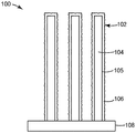
도 1은 본 명세서에 기재된 예시적인 촉매의 측면도이다.
도 1a는 본 명세서에 기재된 예시적인 촉매의 측면도이다.
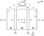
도 2는 예시적인 연료 전지의 개략도이다.
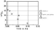
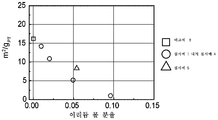
도 3a는 백금 함량에 대해 정규화된, 실시예 1 내지 실시예 5 및 비교예 A 촉매의 전극촉매 질량 활성의 플롯이다.
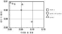
도 3b는 총 백금족 금속 함량에 대해 정규화된, 실시예 1 내지 실시예 5 및 비교예 A 촉매의 전극촉매 활성의 플롯이다.
도 3c는 백금 함량에 대해 정규화된, 실시예 1 내지 실시예 5 및 비교예 A 촉매의 전극촉매 표면적의 플롯이다.
도 3d는 총 백금족 금속 함량에 대해 정규화된, 실시예 1 내지 실시예 5 및 비교예 A 촉매의 전극촉매 표면적의 플롯이다.
도 3e는 실시예 1 내지 실시예 5 및 비교예 A 촉매의 연료 전지 성능의 플롯이다.Figure 1 is a side view of an exemplary catalyst described herein.
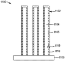
IA is a side view of the exemplary catalyst described herein.
2 is a schematic diagram of an exemplary fuel cell.
3A is a plot of the electrocatalyst mass activity of the catalysts of Examples 1 to 5 and Comparative Example A normalized to the platinum content.
Figure 3b is a plot of the electrode catalytic activity of the catalysts of Examples 1 to 5 and Comparative Example A normalized to the total platinum group metal content.
3C is a plot of the electrocatalyst surface area of the catalysts of Examples 1 to 5 and Comparative Example A normalized to the platinum content.
Figure 3d is a plot of the electrode catalyst surface area of the catalysts of Examples 1 to 5 and Comparative Example A normalized to the total platinum group metal content.
Figure 3E is a plot of fuel cell performance of the catalysts of Examples 1 to 5 and Comparative Example A;
도 1을 참조하면, 기재(108; substrate) 상의 예시적인 촉매(100)는 PtNiAu를 포함하는 나노다공성 산소 환원 촉매 재료(106)에 의해 적어도 부분적으로 덮인 외부 표면(105)을 갖는 미세구조화된 위스커(104)를 갖는 나노구조화된 요소(102)를 갖는다.1, an
본 명세서에 기재된 나노다공성 산소 환원 촉매 재료를 제조하는 한 가지 예시적인 방법은One exemplary method of making the nanoporous oxygen reduction catalyst material described herein is < RTI ID = 0.0 >
백금 및 니켈을 포함하는 층이 존재하는, PtNiAu를 포함하는 산소 환원 촉매 재료를 제공하는 단계; 및Providing an oxygen reduction catalyst material comprising PtNiAu in which a layer comprising platinum and nickel is present; And
백금 및 니켈을 포함하는 적어도 일부 층을 탈합금화하여 적어도 하나의 층으로부터 니켈을 제거하여 본 명세서에 기재된 나노다공성 산소 환원 촉매 재료를 제공하는 단계를 포함한다.De-alloying at least some layers comprising platinum and nickel to remove nickel from at least one layer to provide the nanoporous oxygen reduction catalyst material described herein.
본 명세서에 기재된 나노다공성 산소 환원 촉매 재료를 제조하는 다른 예시적인 방법은Other exemplary methods of making the nanoporous oxygen reduction catalyst materials described herein include,
백금 및 니켈을 포함하는 타겟으로부터 백금 및 니켈을 침착시켜 백금 및 니켈을 포함하는 제1 층을 제공하는 단계;Depositing platinum and nickel from a target comprising platinum and nickel to provide a first layer comprising platinum and nickel;
금을 포함하는 타겟으로부터 금을 포함하는 층을 침착시키는 단계;Depositing a layer comprising gold from a target comprising gold;
전술한 두 단계를, 순서대로, 적어도 1회 반복하는 단계(일부 실시 형태에서, 2, 3, 4, 5, 10, 15, 20, 25, 50, 75, 100, 150, 200, 250회, 또는 심지어 적어도 275회 반복함); 및Repeating the above two steps in order, at least once (in some
백금 및 니켈을 포함하는 적어도 하나의 층을 탈합금화하여 층으로부터 니켈을 제거하여 본 명세서에 기재된 나노다공성 산소 환원 촉매 재료를 제공하는 단계를 포함한다.De-alloying at least one layer comprising platinum and nickel to remove nickel from the layer to provide the nanoporous oxygen reduction catalyst material described herein.
도 1a를 참조하면, 일부 실시 형태에서, 탈합금화된 층(들)은, 기공(1110)을 갖는 PtNiAu를 포함하는 촉매 재료(1106)에 의해 적어도 부분적으로 덮인 외부 표면(1105)을 갖는 미세구조화된 위스커(1104)를 갖는 나노구조화된 요소(1102)를 갖는, 기재(1108) 상의 예시적인 촉매(1100)와 같은 촉매의 일부이다.1A, in some embodiments, the de-alloyed layer (s) may comprise a microstructure having an
적합한 위스커는 미국 특허 제4,812,352호(데브(Debe)), 제5,039,561호(데브), 제5,338,430호(파스니지(Parsonage) 등), 제6,136,412호(스파이웍(Spiewak) 등), 및 제7,419,741호(번스트롬(Vernstrom) 등)에 기재된 것들을 비롯하여 당업계에 공지된 기법에 의해 제공될 수 있으며, 이들의 개시 내용은 본 명세서에 참고로 포함된다. 일반적으로, 나노구조화된 위스커는, 예를 들어, 기재(예컨대, 미세구조화된 촉매 전사 중합체 시트) 상에 유기 또는 무기 재료의 층을 (예컨대, 승화에 의해) 진공 침착시킨 다음, 페릴렌 레드 침착인 경우에, 열적 어닐링에 의해 페릴렌 레드 안료를 나노구조화된 위스커로 변환시킴으로써 제공될 수 있다. 전형적으로, 진공 침착 단계는 약 10-3 토르 또는 0.1 파스칼 이하의 총 압력에서 수행된다. 예시적인 미세구조는 유기 염료 씨.아이. 피그먼트 레드(C.I. Pigment Red) 149(즉, N,N'-다이(3,5-자일릴)페릴렌-3,4:9,10-비스(다이카르복스이미드))의 열 승화 및 진공 어닐링에 의해 제조된다. 유기 나노구조화된 층을 제조하는 방법은, 예를 들어, 문헌[Materials Science and Engineering, A158 (1992), pp. 1-6]; 문헌[J. Vac. Sci. Technol. A, 5, (4), July/August 1987, pp. 1914-16]; 문헌[J. Vac. Sci. Technol. A, 6, (3), May/August 1988, pp. 1907-11]; 문헌[Thin Solid Films, 186, 1990, pp. 327-47]; 문헌[J. Mat. Sci., 25, 1990, pp. 5257-68]; 문헌[Rapidly Quenched Metals, Proc. of the Fifth Int. Conf. on Rapidly Quenched Metals, Wurzburg, Germany (Sep. 3-7, 1984), S. Steeb et al., eds., Elsevier Science Publishers B.V., New York, (1985), pp. 1117-24]; 문헌[Photo. Sci. and Eng., 24, (4), July/August 1980, pp. 211-16]; 및 미국 특허 제4,340,276호(마피트(Maffitt) 등) 및 제4,568,598호(빌카디(Bilkadi) 등)에 보고되어 있으며, 이들의 개시 내용은 본 명세서에 참고로 포함된다. 탄소 나노튜브 어레이를 사용하는 촉매 층의 특성이 논문["High Dispersion and Electrocatalytic Properties of Platinum on Well-Aligned Carbon Nanotube Arrays", Carbon, 42, (2004), pp. 191-197]에 보고되어 있다. 풀 또는 강모 형태의 규소(grassy or bristled silicon)를 사용하는 촉매 층의 특성이, 예를 들어, 미국 특허 출원 공개 제2004/0048466 A1호(고어(Gore) 등)에 보고되어 있다.Suitable whiskers are described in U.S. Patent No. 4,812,352 (Debe), 5,039,561 (Dev), 5,338,430 (Parsonage et al), 6,136,412 (Spiewak et al.), And 7,419,741 (Vernstrom et al.), The disclosures of which are incorporated herein by reference. Generally, the nanostructured whisker is formed by vacuum depositing a layer of organic or inorganic material (e.g., by sublimation) onto a substrate (e.g., microstructured catalyst transfer polymer sheet) , It can be provided by converting the perylene red pigment into a nanostructured whisker by thermal annealing. Typically, the vacuum deposition step is performed at a total pressure of less than about 10 -3 Torr or 0.1 Pascal. An exemplary microstructure is organic dye seeds. The thermal sublimation of CI Pigment Red 149 (i.e., N, N'-di (3,5-xylyl) perylene-3,4: 9,10-bis (dicarboximide) And is manufactured by annealing. Methods for preparing organic nanostructured layers are described, for example, in Materials Science and Engineering, A158 (1992), pp. 1-6]; J. Vac. Sci. Technol. A, 5, (4), July / August 1987, pp. 1914-16]; J. Vac. Sci. Technol. A, 6, (3), May / August 1988, pp. 1907-11]; Thin Solid Films, 186, 1990, pp. 327-47; J. Mat. Sci., 25, 1990, pp. 5257-68; Rapidly Quenched Metals, Proc. of the Fifth Int. Conf. on Rapidly Quenched Metals, Wurzburg, Germany (Sep. 3-7, 1984), S. Steeb et al., eds., Elsevier Science Publishers BV, New York, (1985), pp. 1117-24; [Photo. Sci. and Eng., 24, (4), July / August 1980, pp. 211-16]; And U.S. Patent No. 4,340,276 (Maffitt et al.) And 4,568,598 (Bilkadi et al.), The disclosures of which are incorporated herein by reference. The characteristics of the catalyst layer using a carbon nanotube array are described in the article "High Dispersion and Electrocatalytic Properties of Platinum on Well-Aligned Carbon Nanotube Arrays ", Carbon, 42, (2004), pp. 191-197. The properties of catalyst layers using grass or bristled silicon have been reported, for example, in U.S. Patent Application Publication No. 2004/0048466 Al (Gore et al.).
진공 침착은 임의의 적합한 장치에서 수행될 수 있다(예를 들어, 미국 특허 제5,338,430호(파스니지 등), 제5,879,827호(데브 등), 제5,879,828호(데브 등), 제6,040,077호(데브 등), 및 제6,319,293호(데브 등), 및 미국 특허 출원 공개 제2002/0004453 A1호(호겐(Haugen) 등)를 참조하며, 이들의 개시 내용은 본 명세서에 참고로 포함된다). 한 가지 예시적인 장치가 미국 특허 제5,338,430호(파스니지 등)의 도 4a에 개략적으로 도시되고 첨부 명세서에 논의되어 있는데, 기재를 드럼 상에 장착하고, 이어서 위스커를 형성하기 위해 유기 전구체를 어닐링하기 전에 유기 전구체(예를 들어, 페릴렌 레드 안료)를 침착시키기 위한 승화 또는 증발 공급원 위에서 드럼을 회전시킨다.Vacuum deposition can be performed in any suitable apparatus (see, for example, U.S. Patent Nos. 5,338,430 (Pasnigi et al.), 5,879,827 (Devs et al.), 5,879,828 (Dev et al.), 6,040,077 ), And 6,319,293 (Dev et al.), And U.S. Patent Application Publication No. 2002/0004453 Al (Haugen et al.), The disclosures of which are incorporated herein by reference). One exemplary apparatus is schematically illustrated in FIG. 4A of US Pat. No. 5,338,430 (Pasnigi et al.) And discussed in the accompanying specification, wherein a substrate is mounted on a drum, followed by annealing the organic precursor to form a whisker The drum is rotated on a sublimation or evaporation source for depositing an organic precursor (e.g., perylene red pigment).
전형적으로, 침착되는 페릴렌 레드 안료의 공칭 두께는 약 50 nm 내지 500 nm의 범위이다. 전형적으로, 위스커는 평균 단면 치수가 20 nm 내지 60 nm의 범위이고 평균 길이가 0.3 마이크로미터 내지 3 마이크로미터의 범위이다.Typically, the nominal thickness of the deposited perylene red pigment ranges from about 50 nm to 500 nm. Typically, whiskers have an average cross-sectional dimension in the range of 20 nm to 60 nm and an average length in the range of 0.3 micrometer to 3 micrometers.
일부 실시 형태에서, 위스커는 배킹(backing)에 부착된다. 예시적인 배킹은 폴리이미드, 나일론, 금속 포일, 또는 300℃ 이하의 열적 어닐링 온도를 견딜 수 있는 기타 재료를 포함한다. 일부 실시 형태에서, 배킹은 평균 두께가 25 마이크로미터 내지 125 마이크로미터의 범위이다.In some embodiments, the whisker is attached to a backing. Exemplary backing includes polyimide, nylon, metal foil, or other materials capable of withstanding a thermal annealing temperature of 300 DEG C or less. In some embodiments, the backing has an average thickness in the range of 25 micrometers to 125 micrometers.
일부 실시 형태에서, 배킹은 그의 표면들 중 적어도 하나 상에 미세구조를 갖는다. 일부 실시 형태에서, 미세구조는 위스커의 평균 크기의 3배 이상(일부 실시 형태에서, 적어도 4배, 5배, 10배, 또는 그 이상)인 실질적으로 균일하게 형상화되고 크기 설정된 특징부로 구성된다. 미세구조의 형상은, 예를 들어, V형 홈 및 피크(예를 들어, 미국 특허 제6,136,412호(스파이웍 등)를 참조하며, 이의 개시 내용은 본 명세서에 참고로 포함됨) 또는 피라미드(예를 들어, 미국 특허 제7,901,829호(데브 등)를 참조하며, 이의 개시 내용은 본 명세서에 참고로 포함됨)일 수 있다. 일부 실시 형태에서, 일부 분율의 미세구조 특징부는 미세구조화된 피크들의 평균 또는 대다수 위로 주기적인 방식으로 연장되며, 예를 들어 매 31번째 V-홈 피크는 그의 양측에 있는 것들보다 25% 또는 50% 또는 심지어 100% 더 높다. 일부 실시 형태에서, 대다수의 미세구조화된 피크 위로 연장되는 특징부의 이러한 분율은 최대 10%(일부 실시 형태에서, 최대 3%, 2%, 또는 심지어 최대 1%)일 수 있다. 가끔 더 큰 미세구조 특징부의 사용은 롤-투-롤(roll-to-roll) 코팅 작동에서 코팅된 기재가 롤러의 표면 위로 이동할 때 균일하게 더 작은 미세구조 피크를 보호하는 것을 용이하게 할 수 있다. 더 작은 미세구조의 피크가 아니라 가끔 더 큰 특징부가 롤러의 표면에 닿으므로, 기재가 코팅 공정을 통해 이동함에 따라 긁히거나 또는 달리 방해받기 쉬운 나노구조화된 재료 또는 위스커 재료가 훨씬 더 적다. 일부 실시 형태에서, 미세구조 특징부는 막 전극 조립체를 제조하는 데 있어서 촉매가 전사될 막의 두께의 절반보다 실질적으로 더 작다. 이는 촉매 전사 공정 동안, 더 큰 미세구조 특징부가 막을 통과하여 막의 반대측 면 상의 전극과 중첩되지 않도록 하기 위한 것이다. 일부 실시 형태에서, 가장 큰 미세구조 특징부는 막 두께의 1/3 또는 1/4 미만이다. 가장 얇은 이온 교환 막(예컨대, 두께가 약 10 마이크로미터 내지 15 마이크로미터)의 경우, 높이가 약 3 마이크로미터 내지 4.5 마이크로미터 이하인 미세구조화된 특징부를 갖는 기재를 갖는 것이 바람직할 수 있다. 일부 실시 형태에서, V형 또는 다른 미세구조화된 특징부의 측면의 경사도(steepness) 또는 인접한 특징부들 사이의 끼인각은, 라미네이션-전사 공정 동안 촉매 전사의 용이성을 위하여 그리고 기재 배킹의 평면 기하학적 표면에 비하여 미세구조화된 층의 2의 제곱근(1.414)의 표면적으로부터 비롯되는 전극 표면적의 증가를 갖기 위하여, 대략 90°인 것이 바람직할 수 있다.In some embodiments, the backing has a microstructure on at least one of its surfaces. In some embodiments, the microstructure is composed of substantially uniformly shaped and sized features that are at least three times (in some embodiments at least 4 times, 5 times, 10 times, or more) the average size of the whiskers. The shape of the microstructure can be determined by, for example, V-shaped grooves and peaks (see, for example, U.S. Patent No. 6,136,412 (Spiekow et al., The disclosure of which is incorporated herein by reference) or pyramids For example, U.S. Patent No. 7,901,829 (Dev et al.), The disclosure of which is incorporated herein by reference). In some embodiments, the fractional microstructural features extend in a periodic fashion on average or a majority of the microstructured peaks, such that every 31st V-groove peak has a 25% or 50% Or even 100% higher. In some embodiments, this fraction of features extending over a majority of microstructured peaks can be up to 10% (in some embodiments, up to 3%, 2%, or even up to 1%). The use of occasional larger microstructural features may facilitate protecting uniformly smaller microstructure peaks as the coated substrate moves over the surface of the roller in a roll-to-roll coating operation . As the larger feature rubs against the surface of the rollers rather than the peaks of the smaller microstructure, much less nanostructured or whisker material is scratched or otherwise subject to interference as the substrate moves through the coating process. In some embodiments, the microstructural features are substantially less than half the thickness of the film to which the catalyst is to be transferred in fabricating the membrane electrode assembly. This is so that during the catalyst transfer process, the larger microstructure features do not pass through the membrane and overlap with the electrode on the opposite side of the membrane. In some embodiments, the largest microstructural features are less than 1/3 or 1/4 of the film thickness. For thinnest ion exchange membranes (e.g., about 10 micrometers to 15 micrometers in thickness), it may be desirable to have a substrate with microstructured features that are about 3 micrometers to 4.5 micrometers or less in height. In some embodiments, the steepness of the sides of the V-shaped or other microstructured features or the included angle between adjacent features can be reduced for ease of catalyst transfer during the lamination-transfer process and for fine In order to have an increase in the electrode surface area resulting from the surface area of the square root of 1.414 of the structured layer, it may be desirable to have approximately 90 degrees.
일부 실시 형태에서, 탈합금화될 촉매 재료는 백금 및 니켈을 포함하는 층과, 백금 및 니켈을 포함하는 층 상의 금을 포함하는 층을 포함한다.In some embodiments, the catalyst material to be de-alloyed comprises a layer comprising platinum and nickel and a layer comprising gold on a layer comprising platinum and nickel.
일부 실시 형태에서, 백금 및 니켈을 포함하는 탈합금화될 촉매 재료의 층은 0.4 nm 내지 70 nm의 범위(일부 실시 형태에서, 0.4 nm 내지 1 nm, 0.4 nm 내지 5 nm, 1 nm 내지 25 nm, 또는 심지어 1 nm 내지 10 nm의 범위)의 평면 등가 두께(planar equivalent thickness)를 가지며, 금을 포함하는 층은 0.01 nm 내지 20 nm의 범위(일부 실시 형태에서, 0.01 nm 내지 10 nm, 0.01 nm 내지 5 nm, 0.02 nm 내지 2.5 nm, 또는 심지어 0.02 nm 내지 1 nm의 범위)의 평면 등가 두께(즉, 실질적으로 편평한 평면 기재 상에 침착되는 경우의 두께)를 갖는다. 일부 실시 형태에서, 백금 및 니켈을 포함하는 탈합금화될 촉매 재료의 층(들)은 총체적으로 최대 600 nm(일부 실시 형태에서, 최대 575 nm, 550 nm, 500 nm, 400 nm, 300 nm, 200 nm, 100 nm, 75 nm, 50 nm, 25 nm, 10 nm, 5 nm, 2.5 nm, 1 nm, 또는 심지어 최대 2개의 단층(예를 들어, 0.4 nm); 일부 실시 형태에서, 0.4 nm 내지 600 nm, 0.4 nm 내지 500 nm, 1 nm 내지 500 nm, 5 nm 내지 500 nm, 10 nm 내지 500 nm, 10 nm 내지 400 nm, 또는 심지어 40 nm 내지 300 nm의 범위)의 평면 등가 두께를 갖고, 금을 포함하는 층은 최대 50 nm(일부 실시 형태에서, 최대 45 nm, 40 nm, 35 nm, 30 nm, 25 nm, 20 nm, 15 nm, 10 nm, 5 nm, 4 nm, 3 nm, 2 nm, 1 nm, 단층(예를 들어, 0.2 nm) 또는 심지어 단층 미만(예를 들어, 0.01 nm); 일부 실시 형태에서, 0.01 nm 내지 50 nm, 1 nm 내지 50 nm, 5 nm 내지 40 nm, 또는 심지어 5 nm 내지 35 nm의 범위)의 평면 등가 두께를 갖는다.In some embodiments, the layer of catalyst material to be de-alloyed comprising platinum and nickel is in the range of 0.4 nm to 70 nm (in some embodiments, 0.4 nm to 1 nm, 0.4 nm to 5 nm, 1 nm to 25 nm, Or even planar equivalent thickness in the range of 1 nm to 10 nm), and the layer containing gold is in the range of 0.01 nm to 20 nm (in some embodiments, 0.01 nm to 10 nm, 5 nm, 0.02 nm to 2.5 nm, or even 0.02 nm to 1 nm) (i.e., the thickness when deposited on a substantially flat planar substrate). In some embodiments, the layer (s) of the catalyst material to be de-alloyed, including platinum and nickel, may be grown to a total of at most 600 nm (in some embodiments up to 575 nm, 550 nm, 500 nm, 400 nm, (e. g., 0.4 nm), in some embodiments from 0.4 nm to 600 nm, in some embodiments, from about 0.5 nm to about 100 nm, having a planar equivalent thickness in the range of from 1 nm to 500 nm, from 1 nm to 500 nm, from 5 nm to 500 nm, from 10 nm to 500 nm, from 10 nm to 400 nm, or even from 40 nm to 300 nm, (In some embodiments up to 45 nm, 40 nm, 35 nm, 30 nm, 25 nm, 20 nm, 15 nm, 10 nm, 5 nm, 4 nm, 3 nm, 2 nm (E.g., 0.01 nm); in some embodiments, between 0.01 nm and 50 nm, 1 nm to 50 nm, 5 nm to 40 nm, or even 1 nm, Even in the range of 5 nm to 35 nm).
일부 실시 형태에서, 탈합금화될 촉매 재료는 교번하는, 백금 및 니켈을 포함하는 층 및 금을 포함하는 층(즉, 백금 및 니켈을 포함하는 층, 금을 포함하는 층, 백금 및 니켈을 포함하는 층, 금을 포함하는 층 등)을 포함한다. 일부 실시 형태에서, 적어도 2, 3, 4, 5, 10, 15, 20, 25, 50, 75, 100, 150, 200, 250 세트, 또는 심지어 적어도 275 세트의 교번하는 층.In some embodiments, the catalyst material to be de-alloyed comprises a layer comprising alternating platinum and nickel and a layer comprising gold (i. E., A layer comprising platinum and nickel, a layer comprising gold, platinum and nickel) A layer including gold, a layer containing gold, and the like). In some embodiments, alternating layers of at least 2, 3, 4, 5, 10, 15, 20, 25, 50, 75, 100, 150, 200, 250 sets, or even at least 275 sets.
개개의 침착된 촉매 층의 두께는, 예를 들어, 층의 면적 촉매 로딩량(loading) 및 촉매 밀도에 따라 좌우될 수 있다. 예를 들어, 평면 기재 상에 침착된, 1 ㎠ 평면 면적당 10 마이크로그램의 Pt 및 21.45 g/㎤의 밀도를 갖는 Pt의 단일 층의 두께는 4.7 nm으로서 계산되며, 동일한 면적 로딩량을 갖는 Ni 층의 두께는 11.2 nm이다.The thickness of the individual deposited catalyst layers may depend, for example, on the area loading of the layers and on the catalyst density. For example, the thickness of a single layer of Pt deposited on a planar substrate, Pt of 10 micrograms per 1 cm 2 planar area and density of 21.45 g / cm 3 is calculated as 4.7 nm, and a Ni layer Is 11.2 nm.
일부 실시 형태에서, 탈합금화될 촉매 재료는 백금을 포함하는 층, 백금을 포함하는 층 상의 니켈을 포함하는 층, 및 니켈을 포함하는 층 상의 금을 포함하는 층을 포함한다. 일부 실시 형태에서, 탈합금화될 촉매 재료는 니켈을 포함하는 층, 니켈을 포함하는 층 상의 백금을 포함하는 층, 및 백금을 포함하는 층 상의 금을 포함하는 층을 포함한다. 일부 실시 형태에서, 탈합금화될 촉매 재료는 백금, 니켈, 및 금의 반복하는 순차적인 개별 층을 포함한다. 일부 실시 형태에서, 적어도 2, 3, 4, 5, 10, 15, 20, 25, 50, 75, 100, 150, 200, 250 세트, 또는 심지어 적어도 275 세트의 반복하는 층.In some embodiments, the catalyst material to be de-alloyed comprises a layer comprising platinum, a layer comprising nickel on the layer comprising platinum, and a layer comprising gold on the layer comprising nickel. In some embodiments, the catalyst material to be de-alloyed comprises a layer comprising nickel, a layer comprising platinum on the layer comprising nickel, and a layer comprising gold on the layer comprising platinum. In some embodiments, the catalyst material to be de-alloyed comprises a repeating sequential individual layer of platinum, nickel, and gold. In some embodiments, at least 2, 3, 4, 5, 10, 15, 20, 25, 50, 75, 100, 150, 200, 250 sets, or even at least 275 sets of repeating layers.
일부 실시 형태에서, 탈합금화될 촉매 재료는 노출된 금 표면 층을 갖는다.In some embodiments, the catalyst material to be de-alloyed has an exposed gold surface layer.
일부 실시 형태에서, 백금 및 니켈을 포함하는 탈합금화될 촉매 재료의 각각의 층은 독립적으로 최대 100 nm(일부 실시 형태에서, 최대 50 nm, 20 nm, 15 nm, 10 nm, 5 nm, 4 nm, 3 nm, 2 nm, 1 nm, 단층(예를 들어, 0.2 nm), 또는 심지어 단층 미만(예를 들어, 0.01 nm); 일부 실시 형태에서, 0.01 nm 내지 100 nm, 0.01 nm 내지 50 nm, 0.1 nm 내지 15 nm, 0.1 nm 내지 10 nm, 또는 심지어 1 nm 내지 5 nm의 범위)의 평면 등가 두께를 갖는다.In some embodiments, each layer of the catalyst material to be de-alloyed, including platinum and nickel, is independently a maximum of 100 nm (in some embodiments, up to 50 nm, 20 nm, 15 nm, 10 nm, 5 nm, (E.g., 0.01 nm); in some embodiments, between 0.01 nm and 100 nm, between 0.01 nm and 50 nm, and between 1 nm and 2 nm, 1 nm, 0.1 nm to 15 nm, 0.1 nm to 10 nm, or even 1 nm to 5 nm).
일반적으로, 탈합금화될 촉매 재료는 당업계에 공지된 기법에 의해 침착될 수 있다. 예시적인 침착 기법은 스퍼터링(반응성 스퍼터링 포함), 원자 층 침착, 분자 유기 화학 증착, 분자 빔 에피택시, 열 물리적 증착, 전기분무 이온화에 의한 진공 침착, 및 펄스 레이저 침착으로 이루어진 군으로부터 독립적으로 선택되는 것들을 포함한다. 추가의 일반적인 상세 사항은, 예를 들어, 미국 특허 제5,879,827호(데브 등), 제6,040,077호(데브 등), 및 제7,419,741호(번스트롬 등)에서 찾아 볼 수 있으며, 이들의 개시 내용은 본 명세서에 참고로 포함된다. 열 물리적 증착 방법은 (예를 들어, 저항 가열, 전자빔 총(electron beam gun), 또는 레이저를 통한) 적합한 승온을 사용하여 타겟(target)(소스 재료)을 용융시키거나 증기 상태로 승화시키고, 이어서 이를 진공 공간에 통과시킨 다음, 기화된 형태를 기재 표면 상에 응축시킨다. 열 물리적 증착 장비는 당업계에서 공지되어 있으며, 예를 들어, 금속 증발기 또는 유기 분자 증발기로서 각각 독일 드레스덴 소재의 크레아피즈 게엠베하(CreaPhys GmbH)로부터 상표명 "메탈 이배포레이터(METAL EVAPORATOR)(ME-시리즈)" 또는 "오가닉 몰레큘러 이배포레이터(Organic Molecular Evaporator)(DE-시리즈)"로 입수가능한 것들을 포함하고; 유기 재료 증발기의 다른 예는 영국 옥스포드셔 소재의 맨티스 디포지션 리미티드(Mantis Deposition LTD.)로부터 상표명 "오가닉 머티리얼스 이배포레이터(ORGANIC MATERIALS EVAPORATIOR) (ORMA-시리즈)"로 입수가능하다. 다수의 교번하는 층을 포함하는 탈합금화될 촉매 재료는, 예를 들어, 다수의 타겟으로부터 스퍼터링될 수 있거나(예를 들어, Pt는 제1 타겟으로부터 스퍼터링되고, Ni는 제2 타겟으로부터 스퍼터링되고, Au는 제3 타겟으로부터 스퍼터링됨), 또는 하나를 초과하는 원소(예를 들어, Pt와 Ni)를 포함하는 타겟(들)으로부터 스퍼터링될 수 있다. 촉매 코팅이 단일 타겟으로 수행되는 경우, 촉매 코팅의 응축열이, 적용되는 경우, 하부의 촉매 또는 지지체, Pt, Ni, 또는 Au 원자와 기재 표면을, 상기 원자들이 잘 혼합되어 열역학적으로 안정한 합금 도메인을 형성하는 데 충분한 표면 이동성을 제공할 만큼 충분히 가열하도록, 코팅 층은 가스 분배 층, 가스 분산 층, 촉매 전사 층 또는 막 상에 단일 단계로 적용되는 것이 바람직할 수 있다. 대안적으로, 예를 들어, 기재는 또한 이러한 원자 이동성을 촉진하도록 고온으로 제공되거나 또는 가열될 수 있다. 일부 실시 형태에서, 스퍼터링은 적어도 아르곤의 혼합물을 포함하는 분위기에서 적어도 부분적으로 수행된다. 유기금속 형태의 촉매는, 예를 들어, 질량-선택된 이온의 연착륙 또는 반응성 착륙에 의해 침착될 수 있다. 질량-선택된 이온의 연착륙을 이용하여 유기 리간드가 완비된 촉매적으로-활성인 금속 착물을 가스상으로부터 불활성 표면 상으로 전달한다. 이 방법은, 한정된 활성 부위를 갖는 재료를 준비함으로써, 주위 조건 또는 전통적 진공 조건 중 어느 하나 하에서, 고도로 제어된 방식으로 표면의 분자 설계를 달성하는 데 사용될 수 있다. 추가적인 상세 사항에 대하여, 예를 들어, 문헌[Johnson et al., Anal. Chem., 2010, 82, pp. 5718-5727], 및 문헌[Johnson et al., Chemistry: A European Journal, 2010, 16, pp. 14433-14438]을 참조하며, 이들의 개시 내용은 본 명세서에 참고로 포함된다.In general, the catalyst material to be dealloyed may be deposited by techniques known in the art. Exemplary deposition techniques are independently selected from the group consisting of sputtering (including reactive sputtering), atomic layer deposition, molecular organic chemical vapor deposition, molecular beam epitaxy, thermal physical deposition, vacuum deposition by electrospray ionization, and pulsed laser deposition ≪ / RTI > Further general details can be found, for example, in U.S. Patent No. 5,879,827 (Dev et al.), 6,040,077 (Dev et al.), And 7,419,741 (Burnström et al) Are incorporated herein by reference. The thermal physical vapor deposition process may be performed by melting or vaporizing the target (source material) using a suitable elevated temperature (e.g., through resistive heating, electron beam gun, or laser) This is passed through a vacuum space and then the vaporized form is condensed on the substrate surface. Thermal physical vapor deposition equipment is known in the art and is commercially available, for example, from CreaPhys GmbH, Dresden, Germany as METAL EVAPORATOR (ME- Series "or" Organic Molecular Evaporator (DE-series) " Another example of an organic material evaporator is available from Mantis Deposition LTD, Oxfordshire, UK under the trade designation "ORGANIC MATERIALS EVAPORATIOR (ORMA-series) ". The catalyst material to be de-alloyed comprising a plurality of alternating layers can be, for example, sputtered from multiple targets (e.g., Pt is sputtered from a first target, Ni is sputtered from a second target, Au may be sputtered from a third target), or from a target (s) comprising more than one element (e.g., Pt and Ni). When the catalytic coating is carried out with a single target, the heat of condensation of the catalytic coating, if applied, will cause the lower catalyst or support, Pt, Ni, or Au atoms and the substrate surface to become thermodynamically stable alloy domains It may be desirable to apply the coating layer in a single step on the gas distribution layer, the gas dispersion layer, the catalyst transfer layer, or the film so as to sufficiently heat to provide sufficient surface mobility to form. Alternatively, for example, the substrate may also be provided at a high temperature or heated to promote such atomic mobility. In some embodiments, sputtering is performed at least partially in an atmosphere comprising at least a mixture of argon. Catalysts in organometallic form can be deposited by, for example, soft landing or reactive landing of mass-selected ions. Mass-transfer of the catalytically-active metal complex, complete with organic ligands, from the gas phase onto the inert surface using soft landings of selected ions. This method can be used to achieve molecular design of the surface in a highly controlled manner under either ambient conditions or traditional vacuum conditions, by preparing a material with defined active sites. For further details, see, for example, Johnson et al., Anal. Chem., 2010, 82, pp. 5718-5727, and Johnson et al., Chemistry: A European Journal, 2010, 16, pp. 14433-14438, the disclosures of which are incorporated herein by reference.
일부 실시 형태에서, 탈합금화 전에 또는 후에 촉매 재료의 백금 대 금의 중량비는 3:1 내지 250:1의 범위(일부 실시 형태에서, 5:1 내지 15:1, 3:1 내지 30:1, 30:1 내지 250:1, 또는 심지어 15:1 내지 250:1의 범위)이다.In some embodiments, the weight ratio of platinum to gold in the catalyst material before or after dealloying is in the range of 3: 1 to 250: 1 (in some embodiments, 5: 1 to 15: 1, 3: 1 to 30: 30: 1 to 250: 1, or even 15: 1 to 250: 1).
일부 실시 형태에서, 탈합금화된 촉매 재료를 제조하는 방법은 백금 및 니켈을 포함하는 타겟(예를 들어, Pt3Ni7 타겟)으로부터 백금 및 니켈을 침착시키는 단계, 및 금을 포함하는 타겟으로부터 금을 침착시키는 단계를 포함한다. 일부 실시 형태에서, 백금 및 니켈을 포함하는 층은 0.4 nm 내지 580 nm의 범위(일부 실시 형태에서, 0.4 nm 내지 72 nm의 범위)의 평면 등가 두께를 갖고, 금을 포함하는 층은 0.01 nm 내지 32 nm의 범위(일부 실시 형태에서, 0.01 nm 내지 16 nm의 범위, 또는 심지어 0.01 nm 내지 2 nm의 범위)의 평면 등가 두께를 갖는다.In some embodiments, a method of making a de-alloyed catalyst material comprises depositing platinum and nickel from a target (e.g., a Pt 3 Ni 7 target) comprising platinum and nickel, and depositing platinum and nickel from the target, . ≪ / RTI > In some embodiments, the layer comprising platinum and nickel has a planar equivalent thickness in the range of 0.4 nm to 580 nm (in some embodiments, in the range of 0.4 nm to 72 nm) (In some embodiments, in the range of 0.01 nm to 16 nm, or even in the range of 0.01 nm to 2 nm).
일부 실시 형태에서, 본 명세서에 기재된 촉매를 제조하는 방법은 백금을 포함하는 타겟으로부터 백금을 침착시키는 단계, 니켈을 포함하는 타겟으로부터 니켈을 침착시키는 단계, 및 금을 포함하는 타겟으로부터 금을 침착시키는 단계를 포함한다. 일부 실시 형태에서, 백금을 포함하는 층, 니켈을 포함하는 인접 층, 및 금을 포함하는 인접 층은 총체적으로 0.5 nm 내지 50 nm 범위(일부 실시 형태에서, 0.5 nm 내지 30 nm 범위)의 평면 등가 두께를 갖는다. 일부 실시 형태에서, 백금을 포함하는 층은 0.2 nm 내지 30 nm의 범위(일부 실시 형태에서, 0.2 nm 내지 20 nm, 또는 심지어 0.2 nm 내지 10 nm의 범위)의 평면 등가 두께를 갖고, 니켈을 포함하는 층은 0.2 nm 내지 50 nm의 범위(일부 실시 형태에서, 0.2 nm 내지 25 nm, 또는 심지어 0.2 nm 내지 10 nm의 범위)의 평면 등가 두께를 갖고, 금을 포함하는 층은 0.01 nm 내지 20 nm의 범위(일부 실시 형태에서, 0.01 nm 내지 10 nm, 0.01 nm 내지 5 nm, 0.02 nm 내지 5 nm, 0.02 nm 내지 1 nm, 또는 심지어 0.1 nm 내지 1 nm의 범위)의 평면 등가 두께를 갖는다. 일부 실시 형태에서, 백금 대 금의 중량비는 3:1 내지 250:1의 범위(일부 실시 형태에서, 5:1 내지 15:1, 3:1 내지 30:1, 30:1 내지 250:1, 또는 심지어 15:1 내지 250:1의 범위)이다.In some embodiments, a method of making a catalyst as described herein comprises depositing platinum from a target comprising platinum, depositing nickel from a target comprising nickel, and depositing gold from the target comprising gold . In some embodiments, a layer comprising platinum, an adjacent layer comprising nickel, and an adjacent layer comprising gold generally have planar equivalents in the range of 0.5 nm to 50 nm (in some embodiments, in the range of 0.5 nm to 30 nm) Thickness. In some embodiments, the layer comprising platinum has a planar equivalent thickness in the range of 0.2 nm to 30 nm (in some embodiments, in the range of 0.2 nm to 20 nm, or even 0.2 nm to 10 nm) Layer has a planar equivalent thickness in the range of 0.2 nm to 50 nm (in some embodiments, in the range of 0.2 nm to 25 nm, or even 0.2 nm to 10 nm), and the layer containing gold has a thickness of from 0.01 nm to 20 nm (In some embodiments, 0.01 nm to 10 nm, 0.01 nm to 5 nm, 0.02 nm to 5 nm, 0.02 nm to 1 nm, or even 0.1 nm to 1 nm). In some embodiments, the weight ratio of platinum to gold is in the range of from 3: 1 to 250: 1 (in some embodiments from 5: 1 to 15: 1, from 3: 1 to 30: 1, from 30: Or even in the range of 15: 1 to 250: 1).
나노다공성은 전형적으로 촉매 재료를 탈합금화하여 니켈의 일부분을 제거함으로써 제공된다. 일반적으로, 탈합금화는 "자유 부식" 접근법(예를 들어, 산 중의 침지)을 통한 것 또는 전기화학적 처리(예를 들어, 산성 매질 중에서의 전위 사이클링)를 통한 것을 비롯하여 당업계에 공지된 기법에 의해 달성될 수 있다. 나노다공성 형성은 전형적으로 탈합금화 매질에서 충분히 상이한 용해 속도를 갖는 적어도 2가지 성분을 포함하는 합금에서 그리고 더 많은 귀한 성분이 충분한 표면 이동성을 가질 때 일어난다. 추가적인 상세 사항에 대해서는, 예를 들어, 문헌[Erlebacher et al., Nature, 2001, 410, pp. 450-453] 및 미국 특허 제6,805,972 B2호(에를레바허(Erlebacher) 등); 제8,673,773 B2호(오퍼맨(Opperman) 등); 및 제8,895,206 B2호(에를레바허 등)를 참조하며, 이들의 개시 내용은 본 명세서에 참고로 포함된다.Nanoporosity is typically provided by de-alloying the catalyst material to remove a portion of the nickel. In general, de-alloying may be accomplished by techniques known in the art, such as through a "free-corrosion" approach (eg, immersion in acid) or through electrochemical treatment (eg, dislocation cycling in an acidic medium) ≪ / RTI > Nanoporous formation typically occurs in alloys containing at least two components with sufficiently different dissolution rates in the de-alloying media and when more valuable components have sufficient surface mobility. For additional details, see, for example, Erlebacher et al., Nature, 2001, 410, pp. 450-453 and U. S. Patent No. 6,805, 972 B2 (Erlebacher et al.); 8,673,773 B2 (Opperman et al.); And 8,895,206 B2 (Ellrebach et al.), The disclosures of which are incorporated herein by reference.
일부 실시 형태에서, 탈합금화될 촉매 재료 또는 (탈합금화된) 나노다공성 산소 환원 촉매 재료가 어닐링된다. 일부 실시 형태에서, 촉매 재료는 탈합금화 전에 어닐링된다. 일반적으로, 어닐링은, 예를 들어 오븐 또는 노를 통해, 레이저를 이용하여, 적외선 기법을 이용하여 촉매를 가열하는 것을 비롯하여 당업계에 공지된 기법에 의해 행해질 수 있다. 어닐링은, 예를 들어 불활성 또는 반응성 가스 환경에서 수행될 수 있다. 이론에 의해 구애되고자 하지는 않지만, 어닐링은 촉매의 활성 및 내구성에 영향을 줄 수 있는 원자 규모의 구조 변화를 유도할 수 있는 것으로 여겨진다. 게다가, 나노규모 입자 및 필름을 어닐링하는 것은 원자 성분(들)에서 이동성을 유도할 수 있으며, 이는 입자 또는 박막 결정립(grain)의 성장을 야기할 수 있는 것으로 여겨진다. 다원소 혼합물, 합금, 또는 층상 입자 및 필름의 경우에, 어닐링은, 성분 원소 특성 및 어닐링 환경에 따라, 예를 들어, 입자 또는 필름 내의 성분의 표면으로의 편석, 무작위 무질서 합금의 형성, 및 질서 있는 금속간화합물의 형성을 유도할 수 있는 것으로 여겨진다. 어닐링에 관한 추가적인 상세 사항에 대해서는, 예를 들어, 문헌[van der Vliet et al., Nature Materials, 2012, 11, pp. 1051-1058]; 문헌[Wang et al., Nature Materials, 2013, 12, pp. 81-87] 및 미국 특허 제8,748,330 B2호(데브 등)를 참조하며, 이들의 개시 내용은 본 명세서에 참고로 포함된다.In some embodiments, the catalyst material to be de-alloyed or the (de-alloyed) nanoporous oxygen reduction catalyst material is annealed. In some embodiments, the catalyst material is annealed prior to de-alloying. Generally, annealing can be done by techniques known in the art, for example, using an oven or furnace, using a laser, and heating the catalyst using an infrared technique. The annealing can be performed, for example, in an inert or reactive gas environment. Without wishing to be bound by theory, it is believed that annealing can induce atomic-scale structural changes that can affect the activity and durability of the catalyst. In addition, it is believed that annealing nanoscale particles and films can induce mobility in the atomic component (s), which can cause growth of particles or thin film grain. In the case of multi-element mixtures, alloys, or layered particles and films, the annealing may be carried out according to the elemental element characteristics and the annealing environment, for example by segregation into the surface of the particles or components in the film, the formation of random disorder alloys, Which may induce the formation of intermetallic compounds. For further details regarding annealing, see, for example, van der Vliet et al., Nature Materials, 2012, 11, pp. 1051-1058]; Wang et al., Nature Materials, 2013, 12, pp. 81-87 and U.S. Patent No. 8,748,330 B2 (Dev et al.), The disclosures of which are incorporated herein by reference.
일부 실시 형태에서, 본 명세서에 기재된 나노다공성 산소 환원 촉매 재료는 백금 및 니켈을 포함하는 적어도 하나의 나노다공성 층의 형태이다. 일부 실시 형태에서, 백금 및 니켈을 포함하는 나노다공성 층은 최대 600 nm(일부 실시 형태에서, 최대 575 nm, 550 nm, 500 nm, 400 nm, 300 nm, 200 nm, 100 nm, 75 nm, 50 nm, 25 nm, 10 nm, 5 nm, 또는 심지어 최대 2개의 단층(예를 들어, 4 nm); 일부 실시 형태에서, 4 nm 내지 600 nm, 4 nm 내지 500 nm, 10 nm 내지 500 nm, 25 nm 내지 500 nm, 25 nm 내지 400 nm, 또는 심지어 40 nm 내지 300 nm의 범위)의 평면 등가 두께(즉, 실질적으로 편평한 평면 기재 상에 침착되는 경우의 두께)를 갖는다.In some embodiments, the nanoporous oxygen reduction catalyst material described herein is in the form of at least one nanoporous layer comprising platinum and nickel. In some embodiments, the nanoporous layer comprising platinum and nickel has a maximum of 600 nm (in some embodiments, up to 575 nm, 550 nm, 500 nm, 400 nm, 300 nm, 200 nm, 100 nm, 75 nm, 4 nm to 600 nm, 4 nm to 500 nm, 10 nm to 500 nm, 25 nm, 25 nm, 10 nm, 5 nm or even up to 2 monolayers (for example, (i. e., the thickness when deposited on a substantially flat planar substrate) of a thickness of from about 1 nm to about 500 nm, from about 25 nm to about 400 nm, or even from about 40 nm to about 300 nm.
본 명세서에 기재된 나노다공성 산소 환원 촉매 재료의 일부 실시 형태에서, 백금 및 니켈을 포함하는 적어도 하나의 나노다공성 층 상에 금을 포함하는 층이 존재한다. 일부 실시 형태에서, 촉매 재료는 노출된 금 표면 층을 갖는다. 일부 실시 형태에서, 금을 포함하는 층은 최대 50 nm(일부 실시 형태에서, 최대 45 nm, 40 nm, 35 nm, 30 nm, 25 nm, 20 nm, 15 nm, 10 nm, 5 nm, 4 nm, 3 nm, 2 nm, 1 nm, 단층(예를 들어, 0.2 nm) 또는 심지어 단층 미만(예를 들어, 0.01 nm); 일부 실시 형태에서, 0.01 nm 내지 50 nm, 1 nm 내지 50 nm, 5 nm 내지 40 nm, 또는 심지어 5 nm 내지 35 nm의 범위)의 평면 등가 두께를 갖는다.In some embodiments of the nanoporous oxygen reduction catalyst material described herein, there is a layer comprising gold on at least one nanoporous layer comprising platinum and nickel. In some embodiments, the catalyst material has an exposed gold surface layer. In some embodiments, the layer comprising gold may be at most 50 nm (in some embodiments at most 45 nm, 40 nm, 35 nm, 30 nm, 25 nm, 20 nm, 15 nm, 10 nm, (E.g., 0.01 nm); in some embodiments, between 0.01 nm and 50 nm, between 1 nm and 50 nm, between 5 nm and 5 nm, nm to 40 nm, or even in the range of 5 nm to 35 nm).
본 명세서에 기재된 촉매는, 예를 들어, 연료 전지 막 전극 조립체(MEA)에 유용하다. "막 전극 조립체"는 막, 애노드 및 캐소드 전극 층, 및 가스 확산 층을 포함하는 연료 전지 재료의 층상 샌드위치(layered sandwich)를 지칭한다. 전형적으로, 캐소드 촉매 층이 본 명세서에 기재된 촉매를 포함하지만, 일부 실시 형태에서는, 애노드 촉매 층이 독립적으로 본 명세서에 기재된 촉매를 포함한다.The catalysts described herein are useful, for example, in fuel cell membrane electrode assemblies (MEAs). "Membrane electrode assembly" refers to a layered sandwich of a fuel cell material comprising a membrane, an anode and a cathode electrode layer, and a gas diffusion layer. Typically, the cathode catalyst layer comprises the catalyst described herein, but in some embodiments, the anode catalyst layer independently includes the catalyst described herein.
MEA는, 순서대로:The MEA, in order:
서로 반대편에 있는 제1 주 표면 및 제2 주 표면을 갖는 제1 가스 분배 층;A first gas distribution layer having a first major surface and a second major surface opposite to each other;
서로 반대편에 있는 제1 주 표면 및 제2 주 표면을 갖는 애노드 촉매 층으로서, 애노드 촉매는 제1 촉매를 포함하는, 애노드 촉매 층;An anode catalyst layer having a first major surface and a second major surface opposite to each other, the anode catalyst comprising a first catalyst;
전해질 막;An electrolyte membrane;
서로 반대편에 있는 제1 주 표면 및 제2 주 표면을 갖는 캐소드 촉매 층으로서, 캐소드 촉매는 제2 촉매를 포함하는, 캐소드 촉매 층;A cathode catalyst layer having a first major surface and a second major surface opposite to each other, the cathode catalyst comprising a second catalyst;
서로 반대편에 있는 제1 주 표면 및 제2 주 표면을 갖는 제2 가스 분배 층을 포함한다.And a second gas distribution layer having a first major surface and a second major surface opposite to each other.
전해질 막은 애노드 촉매 층과 캐소드 촉매 층 사이에서 반응 중간체 이온을 전도한다. 전해질 막은 바람직하게는 화학적 및 전기화학적 산화 안정성을 비롯하여 전기화학적 환경에서 높은 내구성을 갖는다. 전해질 막은 바람직하게는 반응 중간체 이온의 수송에 대해 낮은 이온 저항을 갖지만, 다른 이온, 전자, 및 반응물 화학종에 대해서는 상대적으로 불투과성인 장벽이다. 일부 실시 형태에서, 전해질 막은 양이온을 전도하는 양성자 교환 막(PEM)이다. PEM 연료 전지에서, 전해질 막은 바람직하게는 양성자를 전도한다. PEM은 전형적으로 구조적 골격 및 펜던트 양이온 교환 기로 구성된 부분 플루오르화된 또는 퍼플루오르화된 중합체이다. PEM은, 예를 들어, 미국 델라웨어주 윌밍턴 소재의 이. 아이. 듀폰 디 네모아 앤드 컴퍼니(E. I. du Pont de Nemours and Company)로부터 상표명 "나피온"(NAFION)으로; 벨기에 브뤼셀 소재의 솔베이(Solvay)로부터 상표명 "아퀴비온"(AQUIVION)으로; 미국 미네소타주 세인트 폴 소재의 쓰리엠 컴퍼니(3M Company)로부터 상표명 "3M PFSA 멤브레인(MEMBRANE)"으로; 그리고 일본 도쿄 소재의 아사히 글래스 컴퍼니(Asahi Glass Co.)로부터 상표명 "플레미온"(FLEMION)으로 입수가능하다.The electrolyte membrane conducts the reaction intermediate ions between the anode catalyst layer and the cathode catalyst layer. The electrolyte membrane preferably has high durability in an electrochemical environment, including chemical and electrochemical oxidation stability. The electrolyte membrane is preferably a barrier that is relatively impermeable to other ion, electron, and reactant species, although it has a low ionic resistance to transport of the reaction intermediate ion. In some embodiments, the electrolyte membrane is a proton exchange membrane (PEM) that conducts cations. In a PEM fuel cell, the electrolyte membrane preferably conducts a proton. The PEM is typically a partially fluorinated or perfluorinated polymer consisting of a structural skeleton and a pendant cation exchanger. PEM is available from, for example, Wilmington, Delaware, USA. children. From E. I. du Pont de Nemours and Company under the trade designation "NAFION "; From Solvay, Brussels, Belgium under the trade name "AQUIVION "; From 3M Company, St. Paul, Minn., Under the trade designation "3M PFSA MEMBRANE "; And available from Asahi Glass Co., Tokyo, Japan under the trade designation "FLEMION ".
가스 분배 층은 일반적으로 가스를 전극에 고르게 전달하고, 일부 실시 형태에서 전기를 전도한다. 그것은 또한, 연료 전지의 경우에, 증기 또는 액체 형태의 물의 제거를 제공한다. 가스 분배 층은 전형적으로 다공성이어서 전극과 유동장 사이의 반응물 및 생성물 수송을 가능하게 한다. 가스 분배 층의 공급원은 다공성 층을 형성하도록 무작위로 배향된, 부직 종이 또는 직조 천의 형태의 탄소 섬유를 포함한다. 부직 탄소 종이는, 예를 들어, 일본 도쿄 소재의 미츠비시 레이온 컴퍼니 리미티드(Mitsubishi Rayon Co., Ltd.)로부터 상표명 "그라필(GRAFIL) U-105"로; 일본 도쿄 소재의 "토레이 코포레이션(Toray Corp.)으로부터 상표명 "토레이"(TORAY)로; 미국 매사추세츠주 로웰 소재의 에브카르브 머티리얼 솔루션즈(AvCarb Material Solutions)로부터 상표명 "애브카르브"(AVCARB)로; 독일 비스바덴 소재의 에스지엘 그룹, 더 카본 컴퍼니(SGL Group, the Carbon Company)로부터 상표명 "시그라세트"(SIGRACET)로; 독일 바인하임 소재의 프로이덴베르크 에프체체테 에스에 운트 코 카게(Freudenberg FCCT SE & Co. KG), 퓨얼 셀 컴포넌트 테크놀로지스(Fuel Cell Component Technologies)로부터 상표명 "프로이덴베르그"(Freudenberg)로; 그리고 미국 코네티컷주 쉘턴 소재의 엔지니어드 파이버스 테크놀로지(Engineered Fibers Technology; EFT)로부터 상표명 "스펙트라카르브(Spectracarb) GDL"로 입수가능하다. 직조 탄소 천 또는 클로스(cloth)는, 예를 들어, 미국 매사추세츠주 워번 소재의 일렉트로 켐 인코포레이티드(Electro Chem Inc.)로부터 상표명 "EC-CC1-060" 및 "EC-AC-클로스"로; 미국 인디애나주 크라운 포인트 소재의 누반트 시스템즈 인코포레이티드(NuVant Systems Inc.)로부터 상표명 "ELAT-LT" 및 "ELAT"로; 바스프 퓨얼 셀 게엠베하(BASF Fuel Cell GmbH), 노스 아메리카(North America)로부터 상표명 "E-TEK ELAT LT"로; 그리고 미국 미주리주 세인트 루이스 소재의 졸텍 코포레이션(Zoltek Corp.)으로부터 상표명 "졸텍 카본 클로스"(ZOLTEK CARBON CLOTH)로 입수가능하다. 부직 종이 또는 직조 천은 그의 소수성을 변경하도록 처리될 수 있다(예를 들어, 후속 건조 및 어닐링에 의한 폴리테트라플루오로에틸렌(PTFE) 현탁액을 이용한 처리). 가스 분산 층은 종종 서브-마이크로미터 전자 전도성 입자(예를 들어, 탄소)의 다공성 층, 및 결합제(예를 들어, PTFE)를 포함한다. 이론에 의해 구애되고자 하지는 않지만, 가스 분산 층은 전극과 가스 분배 층 사이의 반응물 및 생성물 물 수송을 촉진하는 것으로 여겨진다.The gas distribution layer generally delivers gas evenly to the electrodes, and in some embodiments conducts electricity. It also provides for the removal of water in the form of vapor or liquid, in the case of fuel cells. The gas distribution layer is typically porous to allow transport of reactants and products between the electrode and the flow field. The source of the gas distribution layer comprises carbon fibers in the form of nonwoven paper or woven cloth randomly oriented to form a porous layer. Non-woven carbon paper is available, for example, from Mitsubishi Rayon Co., Ltd., Tokyo, Japan under the trade designation "GRAFIL U-105"; From Toray Corp., Tokyo, under the trade designation "TORAY"; from AvCarb Material Solutions, Lowell, Mass., Under the trade designation "AVCARB"; From the SGL Group, the Carbon Company, Wiesbaden, Germany, under the trade designation "SIGRACET "; Freudenberg, Freiberg, FCCT SE & Co. KG, Fuel Cell Component Technologies under the trade designation "Freudenberg" and Engineered Fibers Technology (EFT) in Shelton, Conn. Quot; Spectracarb GDL ". A woven carbon cloth or cloth is available from, for example, Woburn, Mass. EC-CC1-060 " and "EC-AC-Claus" from Electro Chem Inc., NuVant Systems Inc, Crown Point, Indiana, USA From BASF Fuel Cell GmbH, North America to the trade designation "E-TEK ELAT LT "; and from St. Louis, Mo., USA, Available from Zoltek Corp. under the trade designation ZOLTEK CARBON CLOTH. A nonwoven paper or woven fabric can be treated to alter its hydrophobicity (e.g., for subsequent drying and annealing Treatment with a polytetrafluoroethylene (PTFE) suspension by means of a gas diffusion layer The gas dispersion layer often comprises a porous layer of sub-micrometer electronically conductive particles (for example carbon) and a binder (for example PTFE) . Without wishing to be bound by theory, it is believed that the gas distribution layer promotes the transport of reactants and product water between the electrode and the gas distribution layer.
애노드 촉매 또는 캐소드 촉매 중 적어도 하나는 본 명세서에 기재된 나노다공성 산소 환원 촉매 재료를 갖는 위스커를 갖는다. "다른 촉매 층"은 당업계에 공지된 통상적인 촉매일 수 있으며, 당업계에 공지된 기법(예를 들어, 미국 특허 제5,759,944호(부카난(Buchanan) 등), 제5,068,161호(케크(Keck) 등), 및 제4,447,506호(루크작(Luczak) 등))에 의해 제공될 수 있고, 이들의 개시 내용은 본 명세서에 참고로 포함된다.At least one of the anode catalyst or the cathode catalyst has a whisker with the nanoporous oxygen reduction catalyst material described herein. "Other catalyst layers" may be conventional catalysts known in the art and may be prepared by techniques known in the art (see, for example, U.S. Patent No. 5,759,944 (Buchanan et al), 5,068,161 (Keck ), And 4,447,506 (Luczak et al.), The disclosures of which are incorporated herein by reference.
일부 실시 형태에서, 캐소드 촉매 층 및/또는 애노드 촉매 층은 본 명세서에 기재된 나노다공성 산소 환원 촉매 재료를 갖는 위스커를 포함한다.In some embodiments, the cathode catalyst layer and / or the anode catalyst layer comprises a whisker having the nanoporous oxygen reduction catalyst material described herein.
연료 전지는 수소 연료와 공기로부터의 산소를 조합하여 전기, 열 및 물을 생성하는 전기화학 장치이다. 연료 전지는 연소를 이용하지 않으며, 따라서 연료 전지는 위험한 유출물을 있다하더라도 거의 생성하지 않는다. 연료 전지는 수소 연료 및 산소를 직접적으로 전기로 변환하며, 예를 들어, 내연 발전기보다 훨씬 더 높은 효율로 작동될 수 있다.A fuel cell is an electrochemical device that combines hydrogen fuel and oxygen from air to generate electricity, heat, and water. Fuel cells do not utilize combustion, and thus fuel cells produce little if any dangerous effluent. Fuel cells convert hydrogen fuel and oxygen directly into electricity, and can be operated at a much higher efficiency than, for example, internal combustion engines.
도 2를 참조하면, 예시적인 연료 전지(200)는 애노드(203)에 인접한 제1 가스 분배 층(201)을 포함한다. 애노드(203)는 전해질 막(204)에 인접한다. 캐소드(205)가 전해질 막(204)에 인접하여 위치되며, 제2 가스 분배 층(207)이 캐소드(205)에 인접하여 위치된다. 작동 시에, 수소 연료가 연료 전지(200)의 애노드 부분으로 도입되어, 제1 가스 분배 층(201)을 통과하여 애노드(203) 전반에 전달된다. 애노드(203)에서, 수소 연료는 수소 이온(H+)과 전자(e-)로 분리된다.Referring to FIG. 2, an
전해질 막(204)은 수소 이온 또는 양성자만 전해질 막(204)을 통해 연료 전지(200)의 캐소드 부분으로 가게 한다. 전자는 전해질 막(204)을 통과할 수 없고, 대신에, 전류의 형태로 외부 전기 회로를 통해 흐른다. 이러한 전류는 전기 모터와 같은 전기 부하(electric load)(217)에 전력을 공급할 수 있거나, 또는 재충전가능한 배터리와 같은 에너지 저장 장치로 보내질 수 있다.The
산소는 제2 가스 분배 층(207)을 통해 연료 전지(200)의 캐소드 쪽으로 유동한다. 산소가 캐소드(205)를 통과함에 따라, 산소, 양성자, 및 전자가 조합되어 물 및 열을 생성한다.Oxygen flows to the cathode of the
예시적인 실시 형태Exemplary embodiments
1A. PtNiAu를 포함하는 나노다공성 산소 환원 촉매 재료.1A. A nanoporous oxygen reduction catalyst material comprising PtNiAu.
2A. 1 nm 내지 10 nm의 범위(일부 실시 형태에서, 2 nm 내지 8 nm, 또는 심지어 3 nm 내지 7 nm의 범위)의 직경을 갖는 기공을 갖는, 예시적인 실시 형태 1A의 나노다공성 산소 환원 촉매 재료.2A. The nanoporous oxygen reduction catalyst material of Exemplary Embodiment 1A has pores having a diameter in the range of 1 nm to 10 nm (in some embodiments, in the range of 2 nm to 8 nm, or even 3 nm to 7 nm).
3A. PtNiAu 재료는 화학식 PtxNiyAuz(여기서, x는 27.3 내지 29.9의 범위이고, y는 63.0 내지 70.0의 범위이고, z는 0.1 내지 9.6의 범위임)를 갖는, 임의의 선행하는 예시적인 실시 형태 A의 나노다공성 산소 환원 촉매 재료(일부 실시 형태에서, x는 29.4 내지 29.9의 범위이고, y는 68.9 내지 70.0의 범위이고, z는 0.1 내지 2.0의 범위이거나; 또는 심지어 x는 29.7 내지 29.9의 범위이고, y는 69.4 내지 70.0의 범위이고, z는 0.1 내지 0.9의 범위이다).3A. The PtNiAu material has the formula Pt x Ni y Au z where x is in the range of 27.3 to 29.9, y is in the range of 63.0 to 70.0, and z is in the range of 0.1 to 9.6. (In some embodiments, x ranges from 29.4 to 29.9, y ranges from 68.9 to 70.0, z ranges from 0.1 to 2.0, or even x ranges from 29.7 to 29.9 Y is in the range of 69.4 to 70.0, and z is in the range of 0.1 to 0.9.
4A. 백금 및 니켈을 포함하는 적어도 하나의 나노다공성 층의 형태인, 임의의 선행하는 예시적인 실시 형태 A의 나노다공성 산소 환원 촉매 재료.4A. Nanoporous oxygen reduction catalyst material of any of the preceding Exemplary Embodiment A, which is in the form of at least one nanoporous layer comprising platinum and nickel.
5A. 백금 및 니켈을 포함하는 나노다공성 층은 최대 600 nm(일부 실시 형태에서, 최대 575 nm, 550 nm, 500 nm, 400 nm, 300 nm, 200 nm, 100 nm, 75 nm, 50 nm, 25 nm, 10 nm, 5 nm, 2.5 nm, 1 nm, 또는 심지어 최대 2개의 단층(예를 들어, 0.4 nm); 일부 실시 형태에서, 0.4 nm 내지 600 nm, 0.4 nm 내지 500 nm, 1 nm 내지 500 nm, 5 nm 내지 500 nm, 10 nm 내지 500 nm, 10 nm 내지 400 nm, 또는 심지어 40 nm 내지 300 nm의 범위)의 평면 등가 두께를 갖는, 예시적인 실시 형태 4A의 나노다공성 산소 환원 촉매 재료.5A. The nanoporous layer comprising platinum and nickel has a maximum transmittance of 600 nm (in some embodiments up to 575 nm, 550 nm, 500 nm, 400 nm, 300 nm, 200 nm, 100 nm, 75 nm, 50 nm, (E.g., 0.4 nm); in some embodiments, from 0.4 nm to 600 nm, from 0.4 nm to 500 nm, from 1 nm to 500 nm, from 1 nm to 10 nm, from 5 nm to 2.5 nm, The nanoporous oxygen reduction catalyst material of Exemplary Embodiment 4A having a planar equivalent thickness in the range of 5 nm to 500 nm, 10 nm to 500 nm, 10 nm to 400 nm, or even 40 nm to 300 nm.
6A. 백금 및 니켈을 포함하는 나노다공성 층 중 적어도 하나 상에 금을 포함하는 층이 존재하는, 예시적인 실시 형태 4A 또는 5A 중 임의의 실시 형태의 나노다공성 산소 환원 촉매 재료.6A. A nanoporous oxygen reduction catalyst material of any of the exemplary embodiments 4A or 5A, wherein a layer comprising gold is present on at least one of the nanoporous layers comprising platinum and nickel.
7A. 금을 포함하는 층은 최대 50 nm(일부 실시 형태에서, 최대 45 nm, 40 nm, 35 nm, 30 nm, 25 nm, 20 nm, 15 nm, 10 nm, 5 nm, 4 nm, 3 nm, 2 nm, 1 nm, 단층(예를 들어, 0.2 nm) 또는 심지어 단층 미만(예를 들어, 0.01 nm); 일부 실시 형태에서, 0.01 nm 내지 50 nm, 1 nm 내지 50 nm, 5 nm 내지 40 nm, 또는 심지어 5 nm 내지 35 nm의 범위)의 평면 등가 두께를 갖는, 예시적인 실시 형태 6A의 나노다공성 산소 환원 촉매 재료.7A. The layer containing gold may be at most 50 nm in some embodiments up to 45 nm, 40 nm, 35 nm, 30 nm, 25 nm, 20 nm, 15 nm, 10 nm, 5 nm, 4 nm, nm, 1 nm, a single layer (e.g., 0.2 nm) or even a single layer (e.g., 0.01 nm); in some embodiments, from 0.01 nm to 50 nm, 1 nm to 50 nm, 5 nm to 40 nm, Or even in the range of 5 nm to 35 nm) of the planar equivalent thickness.
8A. 노출된 금 표면 층을 갖는, 임의의 선행하는 예시적인 실시 형태 A의 나노다공성 산소 환원 촉매 재료.8A. Nanoporous oxygen reduction catalyst material of any preceding exemplary embodiment A, having an exposed gold surface layer.
9A. 백금 대 금의 중량비는 3:1 내지 250:1의 범위(일부 실시 형태에서, 5:1 내지 15:1, 3:1 내지 30:1, 30:1 내지 250:1, 또는 심지어 15:1 내지 250:1의 범위)인, 임의의 선행하는 예시적인 실시 형태 A의 나노다공성 산화 환원 촉매 재료.9A. The weight ratio of platinum to gold is in the range of from 3: 1 to 250: 1, in some embodiments from 5: 1 to 15: 1, from 3: 1 to 30: 1, from 30: 1 to 250: 1, To 250: 1). ≪ / RTI >
10A. 임의의 선행하는 예시적인 실시 형태 A의 나노다공성 산소 환원 촉매 재료에 의해 적어도 부분적으로 덮인 외부 표면을 갖는 미세구조화된 지지 위스커를 포함하는 나노구조화된 요소를 포함하는 촉매.10A. A catalyst comprising a nanostructured element comprising a microstructured support whisker having an outer surface at least partially covered by a nanoporous oxygen reduction catalyst material of any preceding exemplary embodiment A.
11A. 예시적인 실시 형태 10A의 촉매를 포함하는 연료 전지 막 전극 조립체.11A. A fuel cell membrane electrode assembly comprising the catalyst of Exemplary Embodiment 10A.
1B. 백금 및 니켈을 포함하는 층이 존재하는, PtNiAu를 포함하는 산소 환원 촉매 재료를 제공하는 단계; 및1B. Providing an oxygen reduction catalyst material comprising PtNiAu in which a layer comprising platinum and nickel is present; And
백금 및 니켈을 포함하는 적어도 일부 층을 탈합금화하여 적어도 하나의 층으로부터 니켈을 제거하여 예시적인 실시 형태 1A 내지 9A 중 임의의 실시 형태의 나노다공성 산소 환원 촉매 재료를 제공하는 단계De-alloying at least some layers comprising platinum and nickel to remove nickel from at least one layer to provide a nanoporous oxygen reduction catalyst material of any of the exemplary embodiments 1A-9A
를 포함하는, 방법. 일부 실시 형태에서, 니켈이 제거된, 1 nm 내지 10 nm의 범위(일부 실시 형태에서, 2 nm 내지 8 nm, 또는 심지어 3 nm 내지 7 nm의 범위)의 직경을 갖는 기공이 존재한다./ RTI > In some embodiments, there are pores with diameters ranging from 1 nm to 10 nm (nickel in some embodiments, ranging from 2 nm to 8 nm, or even 3 nm to 7 nm) from which nickel has been removed.
2B. 탈합금화 전에 촉매를 어닐링하는 단계를 추가로 포함하는, 예시적인 실시 형태 1B의 방법.2B. The method of Exemplary Embodiment 1B further comprising annealing the catalyst prior to de-alloying.
3B. 백금 및 니켈을 포함하는 타겟으로부터 백금 및 니켈을 침착시키는 단계, 및 금을 포함하는 타겟으로부터 금을 침착시키는 단계를 추가로 포함하는, 임의의 선행하는 예시적인 실시 형태 B의 방법.3B. The method of any preceding exemplary embodiment B further comprising depositing platinum and nickel from a target comprising platinum and nickel, and depositing gold from a target comprising gold.
4B. 타겟은 Pt3Ni7 타겟인, 예시적인 실시 형태 3B의 방법.4B. The method of Exemplary Embodiment 3B, wherein the target is a Pt 3 Ni 7 target.
5B. 백금을 포함하는 타겟으로부터 백금을 침착시키는 단계, 니켈을 포함하는 타겟으로부터 니켈을 침착시키는 단계, 및 금을 포함하는 타겟으로부터 금을 침착시키는 단계를 추가로 포함하는, 예시적인 실시 형태 1B 또는 2B의 촉매 제조 방법.5B. Comprising the steps of depositing platinum from a target comprising platinum, depositing nickel from a target comprising nickel, and depositing gold from the target comprising gold. ≪ RTI ID = 0.0 > Catalyst.
6B. 백금 및 니켈을 포함하는, 탈합금화 전의, 산소 환원 촉매 재료의 층은 0.4 nm 내지 580 nm의 범위(일부 실시 형태에서, 0.4 nm 내지 72 nm의 범위)의 평면 등가 두께를 갖고, 금을 포함하는 층은 0.01 nm 내지 32 nm의 범위(일부 실시 형태에서, 0.01 nm 내지 16 nm의 범위, 또는 심지어 0.01 nm 내지 2 nm의 범위)의 평면 등가 두께를 갖는, 임의의 선행하는 예시적인 실시 형태 B의 방법.6B. Prior to de-alloying, the layer of oxygen reduction catalyst material, including platinum and nickel, has a planar equivalent thickness in the range of 0.4 nm to 580 nm (in some embodiments, in the range of 0.4 nm to 72 nm) Layer has a planar equivalent thickness in the range of 0.01 nm to 32 nm (in some embodiments, in the range of 0.01 nm to 16 nm, or even in the range of 0.01 nm to 2 nm) in some preceding embodiments B Way.
7B. 백금 대 금의 중량비는 3:1 내지 250:1의 범위(일부 실시 형태에서, 5:1 내지 15:1, 3:1 내지 30:1, 30:1 내지 250:1, 또는 심지어 15:1 내지 250:1의 범위)인, 임의의 선행하는 예시적인 실시 형태 B의 방법.7B. The weight ratio of platinum to gold is in the range of from 3: 1 to 250: 1, in some embodiments from 5: 1 to 15: 1, from 3: 1 to 30: 1, from 30: 1 to 250: 1, To 250: 1). ≪ / RTI >
1C. 예시적인 실시 형태 1A 내지 9A 중 임의의 실시 형태의 촉매를 제조하는 방법으로서, 이 방법은1C. A method of making a catalyst of any of the exemplary embodiments 1A-9A,
백금 및 니켈을 포함하는 타겟으로부터 백금 및 니켈을 침착시켜 백금 및 니켈을 포함하는 제1 층을 제공하는 단계;Depositing platinum and nickel from a target comprising platinum and nickel to provide a first layer comprising platinum and nickel;
금을 포함하는 타겟으로부터 금을 포함하는 층을 침착시키는 단계;Depositing a layer comprising gold from a target comprising gold;
전술한 두 단계를, 순서대로, 적어도 1회 반복하는 단계(일부 실시 형태에서, 2, 3, 4, 5, 10, 15, 20, 25, 50, 75, 100, 150, 200, 250회, 또는 심지어 적어도 275회 반복함); 및Repeating the above two steps in order, at least once (in some
백금 및 니켈을 포함하는 적어도 하나의 층을 탈합금화하여 층으로부터 니켈을 제거하는 단계를 포함하는, 방법. 일부 실시 형태에서, 니켈이 제거된, 1 nm 내지 10 nm의 범위(일부 실시 형태에서, 2 nm 내지 8 nm, 또는 심지어 3 nm 내지 7 nm의 범위)의 직경을 갖는 기공이 존재한다.De-alloying at least one layer comprising platinum and nickel to remove nickel from the layer. In some embodiments, there are pores with diameters ranging from 1 nm to 10 nm (nickel in some embodiments, ranging from 2 nm to 8 nm, or even 3 nm to 7 nm) from which nickel has been removed.
2C. 타겟은 Pt3Ni7 타겟인, 예시적인 실시 형태 1C의 방법.2C. The method of Exemplary Embodiment 1C, wherein the target is a Pt 3 Ni 7 target.
3C. 탈합금화 전에 층들을 어닐링하는 단계를 추가로 포함하는, 임의의 선행하는 예시적인 실시 형태 C의 방법.3C. The method of any preceding exemplary embodiment C further comprising annealing the layers prior to de-alloying.
4C. 백금 및 니켈을 포함하는 층은 0.4 nm 내지 70 nm의 범위(일부 실시 형태에서, 0.4 nm 내지 1 nm, 0.4 nm 내지 5 nm, 1 nm 내지 25 nm, 또는 심지어 1 nm 내지 10 nm의 범위)의 평면 등가 두께를 가지며, 금을 포함하는 층은 0.01 nm 내지 20 nm의 범위(일부 실시 형태에서, 0.01 nm 내지 10 nm, 0.01 nm 내지 5 nm, 0.02 nm 내지 2.5 nm, 또는 심지어 0.02 nm 내지 1 nm의 범위)의 평면 등가 두께를 갖는, 임의의 선행하는 예시적인 실시 형태 C의 방법.4C. The layer comprising platinum and nickel may have a thickness in the range of 0.4 nm to 70 nm (in some embodiments, in the range of 0.4 nm to 1 nm, 0.4 nm to 5 nm, 1 nm to 25 nm, or even 1 nm to 10 nm) Plane equivalent thickness, and the layer comprising gold is in the range of 0.01 nm to 20 nm (in some embodiments, 0.01 nm to 10 nm, 0.01 nm to 5 nm, 0.02 nm to 2.5 nm, or even 0.02 nm to 1 nm Lt; RTI ID = 0.0 > of a < / RTI >
본 발명의 이점 및 실시 형태가 하기 실시예에 의해 추가로 예시되지만, 이들 실시예에 언급된 특정 재료 및 그의 양뿐만 아니라 다른 조건 및 상세 사항은 본 발명을 부당하게 제한하는 것으로 해석되어서는 안 된다. 모든 부 및 백분율은 달리 지시되지 않는 한 중량 기준이다.The advantages and embodiments of the present invention are further illustrated by the following examples, but the specific materials and amounts thereof as well as other conditions and details mentioned in these examples should not be construed as unduly limiting the present invention . All parts and percentages are by weight unless otherwise indicated.
실시예Example
실시예 1 내지 실시예 4Examples 1 to 4
본 명세서에 참고로 포함된 미국 특허 제5,338,430호(파스니지 등), 제4,812,352호(데브), 및 제5,039,561호(데브)에 기재된 공정에 따라, 본 명세서에 또한 참고로 포함된 미국 특허 제6,136,412호에 기재된 미세구조화된 촉매 전사 기재(또는 MCTS)를 기재로서 사용하여, 촉매 지지체로서 이용되는 나노구조화된 위스커를 제조하였다. 페릴렌 레드 안료(즉, N,N'-다이(3,5-자일릴)페릴렌-3,4:9,10-비스(다이카르복스이미드))(미국 노스캐롤라이나주 샬롯 소재의 클래리언트(Clariant)로부터 입수한, "PR149"로도 알려져 있는 씨.아이. 피그먼트 레드(C.I. Pigment Red) 149)를 200 nm의 공칭 두께로 MCTS 상에 승화 진공 코팅하였고, 그 후에 어닐링하였다. 침착 및 어닐링 후에, 큰 종횡비, 약 0.5 내지 2 마이크로미터의 제어가능한 길이, 약 0.03 내지 0.05 마이크로미터의 폭, 및 1 제곱마이크로미터당 약 30개의 위스커의 면적 개수 밀도를 갖는 고도로 배향된 결정 구조가 형성되며, 이는 하부의 기재에 실질적으로 수직으로 배향되었다.According to the processes described in U.S. Patent Nos. 5,338,430 (Pasnigi et al.), 4,812,352 (Dev) and 5,039,561 (Dev), which are incorporated herein by reference, U.S. Patent No. 6,136,412 The nanostructured whiskers used as the catalyst support were prepared using the microstructured catalyst transfer substrate (or MCTS) described in US Pat. Perylene red pigments (i.e., N, N'-di (3,5-xylyl) perylene-3,4: 9,10-bis (dicarboximide)) (Clarion, Charlotte, CI Pigment Red 149, also known as "PR149", obtained from Clariant, was sublimed vacuum coated onto MCTS to a nominal thickness of 200 nm and then annealed. After deposition and annealing, a highly oriented crystal structure is formed having a large aspect ratio, a controllable length of about 0.5 to 2 micrometers, a width of about 0.03 to 0.05 micrometers, and an area count density of about 30 whiskers per square micrometer , Which is oriented substantially perpendicular to the underlying substrate.
나노구조화된 위스커의 층 상에 DC-마크네트론 스퍼터링 공정을 사용하여 촉매 필름을 순차적으로 스퍼터 코팅함으로써 나노구조화된 박막(NSTF) 촉매 층을 제조하였다. 4개의 크라이오 펌프(미국 텍사스주 오스틴 소재의 오스틴 사이언티픽, 옥스포드 인스트루먼츠(Austin Scientific, Oxford Instruments)로부터 입수함), 터보펌프가 장착되고 약 5 mTorr(0.66 Pa)의 전형적인 Ar 스퍼터 가스 압력 및 2 인치 × 10 인치(5 cm × 25.4 cm) 직사각형 스퍼터 타겟(미국 펜실베이니아주 버틀러 소재의 소피스티케이티드 알로이즈 인코포레이티드(Sophisticated Alloys Inc.)로부터 입수함)을 사용하는 진공 스퍼터 침착 시스템(미국 매사추세츠주 로웰 소재의 밀 레인 엔지니어링 코퍼레이션(Mill Lane Engineering Co.)으로부터 모델 커스텀 리서치(Model Custom Research)로 입수함)을 사용하였다. 스퍼터링 가스로서 초고순도 Ar을 사용하여 코팅을 침착시켰다. Pt 및 Ni를 먼저 단일 합금 Pt3Ni7 타겟(30 원자% Pt 및 70 원자% Ni, 미국 펜실베이니아주 버틀러 소재의 소피스티케이티드 알로이즈로부터 입수함)으로부터 동시에 침착시켰다. 각각이 약 2.8 nm의 평면 등가 두께를 갖는 Pt3Ni7의 50개의 층을 침착시켰고, 이는 약 0.10 mgPt/㎠의 면적 Pt 로딩량을 초래하였다. 단일 합금 타겟으로부터 침착된 Pt3Ni7 촉매는 "단일 타겟"(ST)으로 지칭된다. 이어서, Au(미국 오하이오주 메이필드 하이츠 소재의 매터리온(Materion)으로부터 입수함)을 기재 상의 Pt3Ni7-코팅된 NSTF 촉매의 4개의 조각의 표면 상에 후속적으로 침착시켰고, 이들 각각은 전극촉매에서 1, 2, 5, 및 10 원자% Au 함량(각각 실시예 1, 실시예 2, 실시예 3, 및 실시예 4)을 산출하도록 계산된 상이한 Au 면적 로딩량을 가졌다. 실시예 1, 실시예 2, 실시예 3, 및 실시예 4에 대한 Au 층의 평면 등가 두께는 각각 2.1 nm, 4.1 nm, 9.8 nm, 및 20.2 nm이었다. 실시예 1, 실시예 2, 실시예 3, 및 실시예 4에 대한 Pt 대 Au 중량비는 각각 29.4:1, 14.7:1, 5.8:1, 및 2.8:1이었다.Nanostructured thin film (NSTF) catalyst layers were prepared by sequentially sputter coating catalyst films on a layer of nanostructured whiskers using a DC-Markettron sputtering process. A typical Ar sputter gas pressure of about 5 mTorr (0.66 Pa) equipped with a turbo pump and a pressure of about 2 mTorr (0.66 Pa) Vacuum sputter deposition systems using a rectangular inch sputter target (available from Sophisticated Alloys Inc., Butler, Pa.) Inches by 10 inches (5 cm x 25.4 cm) And Model Custom Research from Mill Lane Engineering Co., Lowell, Mass.) Was used. The coating was deposited using ultra high purity Ar as sputtering gas. Pt and Ni were simultaneously deposited from a single alloy Pt 3 Ni 7 target (30 atom% Pt and 70 atom% Ni, available from Sophisticated Alloys, Butler, Pa.). Each deposited 50 layers of Pt 3 Ni 7 having a planar equivalent thickness of about 2.8 nm, resulting in an area Pt loading of about 0.10 mg Pt / cm 2. The Pt 3 Ni 7 catalyst deposited from a single alloy target is referred to as a "single target" (ST). Subsequently, Au (available from Materion, Mayfield Heights, Ohio, USA) was subsequently deposited on the surface of four pieces of Pt 3 Ni 7 -coated NSTF catalyst on the substrate, Had different Au area loading amounts calculated to yield 1, 2, 5, and 10 atomic% Au contents (Example 1, Example 2, Example 3, and Example 4, respectively) in the catalyst. The plane equivalent thicknesses of the Au layers for Example 1, Example 2, Example 3 and Example 4 were 2.1 nm, 4.1 nm, 9.8 nm, and 20.2 nm, respectively. The Pt to Au weight ratios for Example 1, Example 2, Example 3, and Example 4 were 29.4: 1, 14.7: 1, 5.8: 1, and 2.8: 1, respectively.
X-선 형광 분광법(XRF)을 사용하여, 전극촉매의 대표적인 영역을 벌크 조성에 대해 분석하였다. 대표적인 촉매 샘플을, 로듐(Rh) X-선 공급원, 진공 분위기, 및 20 mm 직경 측정 영역이 구비된 파장 분산형 X-선 형광 분광계(일본 도쿄 소재의 리가쿠 코포레이션(Rigaku Corporation)으로부터 상표명 "프리머스(PRIMUS) II"로 입수함)를 사용하여 MCTS 상에서 평가하였다. 각각의 샘플을 3회 분석하여, 로딩량에 비례하는 측정된 Pt, Ni, 및 Au 신호 강도에 대한 평균 및 표준 편차를 얻었다. 실시예 1 내지 실시예 4의 전극촉매의 Pt, Ni, 및 Au 면적 로딩량은, 그들의 측정된 XRF 강도를, 알려진 면적 로딩량으로 Pt, Ni, 및 Au를 함유하는 표준 NSTF 전극촉매를 사용하여 얻어지는 XRF 강도와 비교함으로써 결정하였다. XRF-결정된 Pt, Ni, 및 Au 면적 로딩량으로부터, 촉매의 조성 및 Pt 대 Au 중량비를 계산하였다. Pt 면적 로딩량과 Au 면적 로딩량을 합산함으로써 총 백금족 금속(PGM) 함량을 결정하였다. 로딩량 및 조성 정보가 하기 표 1에 제공되어 있다.Using X-ray fluorescence spectroscopy (XRF), representative regions of the electrode catalyst were analyzed for bulk composition. Representative catalyst samples were prepared using a wavelength dispersive X-ray fluorescence spectrometer equipped with a rhodium (Rh) X-ray source, a vacuum atmosphere and a 20 mm diameter measuring area (available from Rigaku Corporation, Tokyo, Quot; PRIMUS II "). Each sample was analyzed 3 times to obtain the mean and standard deviation of the measured Pt, Ni, and Au signal intensities proportional to the loading amount. The Pt, Ni, and Au area loading amounts of the electrode catalysts of Examples 1 to 4 were determined by measuring their measured XRF intensities using standard NSTF electrode catalysts containing Pt, Ni, and Au at known area loading amounts With the XRF intensity obtained. From the XRF-determined Pt, Ni, and Au area loading amounts, the composition of the catalyst and Pt to Au weight ratios were calculated. The total platinum group metal (PGM) content was determined by summing up Pt area loading and Au area loading. The loading amount and composition information are provided in Table 1 below.
[표 1][Table 1]

이어서, MCTS 상의 PtxNiyAuz 촉매 및 NSTF PtCoMn 코팅된 애노드 촉매 위스커(0.05 mgPt/㎠, Pt69Co28Mn3)를, 라미네이터(미국 오하이오주 웨스트 체스터 타운쉽 소재의 켐 인스트루먼츠, 인코포레이티드(Chem Instruments, Inc.)로부터 상표명 "HL-101"로 입수함)를 사용하여 24 마이크로미터 두께 양성자 교환 막(미국 미네소타주 세인트 폴 소재의 쓰리엠 컴퍼니로부터 상표명 "3M PFSA 825EW"(니트(neat))로 입수가능함)의 양측으로 전달하여 촉매 코팅된 막(CCM)을 형성하였다. 3층 적층물을, 270°F(132℃), 150 psi(1.03 MPa) 닙에서 그리고 0.5 fpm(0.25 cm/s)에 상당하도록 회전하는 고온 닙 롤을 갖는 라미네이터 내로 수동 공급하였다. 라미네이션 직후, 촉매 코팅된 위스커를 PEM의 양측에 매립된 채로 두고, MCTS 층을 박리하였다. 가스 확산 층의 10% 압축을 제공하도록 선택된 개스킷을 갖는 사중 사행 유동장(quad-serpentine flow field)을 갖는 50 ㎠ 활성 면적 시험 전지(미국 뉴멕시코주 앨버커키 소재의 퓨얼 셀 테크놀로지스, 인코포레이티드(Fuel Cell Technologies, Inc.)로부터 상표명 "50 CM2 셀 하드웨어(CELL HARDWARE)"로 입수함) 내에 애노드 및 캐소드 상의 동일한 가스 확산 층(쓰리엠 컴퍼니로부터 상표명 "3M 2979 가스 확산 층"으로 입수가능함)과 함께 CCM을 설치하였다. 본 발명의 촉매를 연료 전지 캐소드로서 평가하였다.The Pt x Ni y Au z catalyst on the MCTS and the NSTF PtCoMn coated anode catalyst whisker (0.05 mg Pt / cm 2, Pt 69 Co 28 Mn 3 ) on the MCTS were then placed in a laminator (Chem Instruments Inc., West Chester Township, 3M PFSA 825EW "from 3M Company, St. Paul, Minn., USA, using a 24 micrometer thick proton exchange membrane (available from Chem Instruments, Inc. under the trade designation" HL- (neat)) to form a catalyst coated membrane (CCM). The three-layer laminate was manually fed into a laminator having a hot nip roll rotating at 270 DEG F (132 DEG C), 150 psi (1.03 MPa) nip and 0.5 fpm (0.25 cm / s). Immediately after lamination, the catalyst coated whiskers were left buried on both sides of the PEM and the MCTS layer was peeled off. A 50 cm 2 active area test cell (Fuel Cell Technologies, Inc., Albuquerque, NM, USA) having a quad-serpentine flow field with a gasket selected to provide 10% compression of the gas diffusion layer With the same gas diffusion layer (available from 3M Company, under the trade designation "3M 2979 gas diffusion layer") on the anode and cathode in a 50 cm 2 cell hardware (available from Fuel Cell Technologies, Inc.) under the trade designation "50 CM2 CELL HARDWARE" CCM was installed. The catalyst of the present invention was evaluated as a fuel cell cathode.
조립 후에, 시험 전지를 시험 스테이션(퓨얼 셀 테크놀로지스, 인코포레이티드로부터 상표명 "싱글 퓨얼 셀 테스트 스테이션"(SINGLE FUEL CELL TEST STATION)으로 입수함)에 연결하였다. 이어서, 컨디셔닝 프로토콜 하에서 약 40시간 동안 MEA를 작동시켜 겉보기 정상 상태 성능을 달성하였다. 프로토콜은, 각각 지속시간이 약 40분 및 45분인, 작동 단계 및 정지 단계의 반복 사이클로 이루어졌다. 작동 단계에서, 각각 800 및 1800 sccm의 H2 및 공기의 일정한 유량으로, 75℃ 전지 온도, 70℃ 이슬점, 101/101 ㎪A H2/공기에서 MEA를 작동시켰다. 40분의 작동 단계 동안, 전지 전압을 0.85 V와 0.25 V 사이의 5분 길이 분극 사이클과 0.40 V에서의 5분 길이 전위 유지 사이에서 교번시킨다. 45분의 정지 단계 동안, 전지 전위를 개방 회로 전압으로 설정하고, 전지로의 H2 및 공기 유동을 중단시키고, 전지 온도를 실온으로 냉각시키면서, 액체 물을 각각 0.26 g/min 및 0.40 g/min으로 애노드 및 캐소드 전지 입구 내로 주입하였다. 이론에 의해 구애됨이 없이, 다수의 전위 사이클을 포함하는 연료 전지 컨디셔닝 프로토콜이 전극촉매 내에 나노기공의 형성을 유도할 수 있는 것으로 여겨진다.After assembly, the test cell was connected to a test station (obtained from Fuel Cell Technologies, Inc. under the trade name "SINGLE FUEL CELL TEST STATION "). The MEA was then operated for about 40 hours under a conditioning protocol to achieve apparent steady-state performance. The protocol consisted of an iterative cycle of operating and stopping phases, each of which had a duration of about 40 minutes and 45 minutes. At the operating stage, the MEA was operated at 75 ° C battery temperature, 70 ° C dew point, 101/101 ㎪AH 2 / air at a constant flow rate of H 2 and air of 800 and 1800 sccm, respectively. During a 40 minute operating phase, the cell voltage is alternated between a 5 minute polarization cycle between 0.85 V and 0.25 V and a 5 minute length potential maintenance at 0.40 V. During the 45 minute stop phase, the liquid potential was set to 0.26 g / min and 0.40 g / min, respectively, while the battery potential was set to the open circuit voltage, H 2 and air flow to the battery were stopped, and the battery temperature was cooled to room temperature Into the anode and cathode cell openings. Without being bound by theory, it is believed that a fuel cell conditioning protocol involving multiple potential cycles can lead to the formation of nanopores in an electrode catalyst.
MEA를 컨디셔닝한 후에, 다음과 같이 기재된, 관련 H2/공기 조건 하에서의 촉매 활성, 표면적 및 작동 성능을 비롯하여 관련 수명 초기(beginning of life; BOL) 특성에 대해 전극촉매를 특성화하였다.After conditioning the MEA, the electrode catalysts were characterized for the relevant beginning of life (BOL) characteristics, including catalytic activity, surface area and operating performance under the relevant H 2 / air conditions, described as follows.
100% H2 기준/상대 전극 대비 900 ㎷에서 1200초 동안 포화 150 ㎪A H2/O2, 80℃ 전지 온도를 사용하여 캐소드 산소 환원 반응(ORR) 절대 활성을 측정하였다. O2 대신에 작동 전극으로 공급되는 N2를 사용하여 측정된 2 ㎷/s 순환 전압전류도(cyclic voltammogram)로부터 추정되는, 전자 단락(electronic shorting) 및 수소 크로스오버(hydrogen crossover) 전류 밀도와 1050초의 유지 시간 후에 측정된 전류 밀도를 더하여 ORR 절대 활성(A/㎠ 또는 mA/㎠)을 얻었다. 단위 귀금속 함량당 촉매 활성의 척도인 전극촉매 질량 활성은, 교정된 ORR 절대 활성(A/㎠평면)을 캐소드 Pt 또는 PGM 면적 로딩량(mg/㎠)으로 나누어서 질량 활성(A/mgPt 또는 A/mgPGM)을 얻음으로써 계산한다. 전극촉매 질량 활성은 하기 표 2와 도 3a 및 도 3b에 제공되어 있다.The cathode oxygen reduction reaction (ORR) absolute activity was measured using a saturated 150 ㎪AH 2 / O 2 , 80 캜 cell temperature for 900 seconds to 1200 hours relative to 100% H 2 standard / counter electrode. The electronic shorting and hydrogen crossover current densities, estimated from a 2 ㎷ / s cyclic voltammogram measured using N 2 supplied to the working electrode instead of O 2 , The ORR absolute activity (A / cm2 or mA / cm2) was obtained by adding the measured current density after the holding time of the second. Measure of the electrode catalyst mass activity of the unit noble metal catalyst activity per content, the corrected ORR absolute activity (A / ㎠ plane) the cathode Pt or PGM area loading amount (mg / ㎠) by dividing the mass activity (A / mg Pt or A / mg PGM ). The electrode catalyst mass activity is provided in Table 2 below and in Figures 3a and 3b.
[표 2][Table 2]

캐소드 촉매 표면 향상 계수(SEF, m2 Pt/m2 평면 또는 유사하게 ㎠Pt/㎠평면)를 포화 101 킬로파스칼 절대 압력(㎪A) H2/N2 및 70℃ 전지 온도 하에서 순환 전압전류법(100 ㎷/s, 0.65 V 내지 0.85 V, 100 스캔의 평균)을 통해 측정하였다. 산화파 및 환원파에 대해 적분된 수소 미달 전위 침착(HUPD) 전하(μC/㎠평면)의 평균을 구하고 220 μC/㎠Pt로 나눔으로써 SEF를 추정하였다. 촉매 분산의 척도인, 전극촉매의 비표면적(m2 Pt/gpt 또는 m2 Pt/gPGM)은 -SEF(m2 Pt/m2 평면)를 면적 Pt 또는 총 백금족 금속(PGM) 로딩량(gPt/m2 평면 또는 gPGM/m2 평면)으로 나누어서 계산하였다. 전극촉매의 비면적은 상기 표 2와 도 3c 및 도 3d에 제공되어 있다.Cathode catalyst surface enhancement factor (SEF, m 2 Pt / m 2 flat or similarly ㎠ Pt / ㎠ plane) a saturated 101 kilopascals absolute pressure (㎪A) H 2 / N 2, and cyclic voltammetry under 70 ℃ cell temperature (100 ㎷ / s, 0.65 V to 0.85 V, average of 100 scans). The SEF was estimated by averaging the accumulated hydrogen - undoped potential (H UPD ) charge (μC / ㎠ plane ) for the oxidation and reduction waves and dividing by 220 μC / ㎠ Pt . The specific surface area (m 2 Pt / g pt or m 2 Pt / g PGM ) of the electrocatalyst, which is a measure of the catalyst dispersion, is defined as -SEF (m 2 Pt / m 2 plane ) as the area Pt or total platinum group metal (PGM) (g Pt / m 2 plane or g PGM / m 2 plane ). The specific area of the electrode catalyst is given in Table 2 and Figs. 3c and 3d.
80℃ 전지 온도, 68℃ 이슬점, 2.0 H2 및 2.5 공기의 일정한 화학량론의 150/150 ㎪A H2/공기에서 측정된 H2/공기 분극 곡선을 통해 전극촉매의 작동 성능을 평가하였다. 전류 밀도를 초기에 20 mA/㎠로 설정하였고, 이어서 전지 전압을 0.40 V 초과로 유지하면서 전류 밀도를 단계적으로 증가시키고, 그 후에 전류 밀도를 다시 20 mA/㎠까지 단계적으로 감소시켰다. 전지를 각각의 전류 밀도에서 2분 동안 유지하였다. 특정 전류 밀도, 20 mA/㎠에서의 전지 전압이 "H2/공기 성능"으로서 보고되며 상기 표 2와 도 3e에 보고되어 있다.The operating performance of the electrode catalyst was evaluated through a H 2 / air polarization curve measured at 150 ° C 150 ㎪AH 2 / air at constant cell stoichiometry of 80 ° C battery temperature, 68 ° C dew point, 2.0 H 2 and 2.5 air. The current density was initially set at 20 mA / cm < 2 >, followed by stepwise increasing the current density while keeping the cell voltage above 0.40 V, and then gradually decreasing the current density to 20 mA / cm < 2 > again. The cell was maintained at each current density for 2 minutes. The specific current density, the cell voltage at 20 mA / cm 2, is reported as "H 2 / air performance" and is reported in Table 2 and Figure 3e above.
실시예 2 촉매를, 전극촉매 금속의 안정성을 평가하는 가속 스트레스 시험(AST) 하에서 추가로 평가하였다. 이 시험에서는, 전지를 80℃ 전지 온도, 200/200 sccm H2/N2, 101 ㎪A, 100% 입구 상대 습도(RH)에서 작동시켰고, 캐소드 전극 전위를 50 ㎷/s의 스캔 속도로 수소 상대/기준 전극에 대비 0.6 V 내지 1.0 V 사이에서 사이클링시켰다. 이론에 의해 구애됨이 없이, 다수의 전위 사이클을 포함하는 AST 프로토콜이 전극촉매 내에 나노기공의 형성을 유도할 수 있는 것으로 여겨진다. 10,000 또는 15,000 AST 사이클 후에, 초기 컨디셔닝 프로토콜을 사용하여 MEA를 약 16시간 동안 재컨디셔닝하였고, 그 후에 캐소드 표면적, ORR 활성, 및 H2/공기 분극 곡선을 다시 측정하여 성능 손실의 속도 및 정도를 결정하였다. 전지가 총 30,000 AST 사이클에 노출되도록, AST, 재컨디셔닝, 및 특성화의 이러한 공정을 반복하였다. 30,000 AST 사이클 후의 비면적, 질량 활성, 및 H2/공기 성능의 변화가 하기 표 3에 열거되어 있다.Example 2 The catalyst was further evaluated under an accelerated stress test (AST) to evaluate the stability of the electrocatalyst metal. In this test, the battery was operated at a battery temperature of 80 ° C, 200/200 sccm H 2 / N 2 , 101 ㎪ A, 100% inlet relative humidity (RH) Counterparts were cycled between 0.6 V and 1.0 V relative to the reference / reference electrode. Without being bound by theory, it is believed that an AST protocol involving multiple potential cycles can lead to the formation of nanopores in an electrode catalyst. After 10,000 or 15,000 AST cycles, the MEA was reconditioned for about 16 hours using an initial conditioning protocol and then the cathode surface area, ORR activity, and H 2 / air polarization curve were again measured to determine the rate and extent of performance loss Respectively. This process of AST, reconditioning, and characterization was repeated to expose the cell to a total of 30,000 AST cycles. The changes in specific area, mass activity, and H 2 / air performance after 30,000 AST cycles are listed in Table 3 below.
[표 3][Table 3]

실시예Example 5 5
Pt3Ni7의 침착 동안 합금 내에 Au 금속을 혼입한 점을 제외하고는, 실시예 1 내지 실시예 4에 대해 기재된 바와 같이 실시예 5를 제조 및 평가하였다.Example 5 was prepared and evaluated as described for Examples 1 to 4, except that Au metal was incorporated into the alloy during the deposition of Pt 3 Ni 7 .
약 1 nm의 평면 등가 두께로 제1 "ST" Pt3Ni7 층을 침착시켰고, 그 상에 Au 층을 침착시켰다. Au 평면 등가 두께는 약 0.08 nm이었다. 약 0.10 mgPt/㎠의 면적 Pt 로딩량이 달성될 때까지 이러한 침착 공정을 135회 반복하였다.The first "ST" Pt 3 Ni 7 layer was deposited with a planar equivalent thickness of about 1 nm, and an Au layer was deposited thereon. The Au plane equivalent thickness was about 0.08 nm. This deposition process was repeated 135 times until an area Pt loading of about 0.10 mg Pt / cm < 2 > was achieved.
로딩량 및 조성 정보가 상기 표 1에 제공되어 있다. 초기 컨디셔닝 후의 촉매 질량 활성, 비면적, 및 H2/공기 성능이 상기 표 2에 보고되어 있으며, 도 3a, 도 3b, 도 3c, 도 3d 및 도 3e에 나타나 있다. 시험된 30,000 AST 사이클 후의 비면적, 질량 활성, 및 H2/공기 성능의 변화가 상기 표 3에 열거되어 있다.The loading amount and composition information are provided in Table 1 above. The catalytic mass activity, area, and H 2 / air performance after initial conditioning are reported in Table 2 above and are shown in Figures 3a, 3b, 3c, 3d and 3e. The changes in specific area, mass activity, and H 2 / air performance after the tested 30,000 AST cycles are listed in Table 3 above.
비교예 AComparative Example A
Au가 촉매 내에 혼입되지 않은 점을 제외하고는, 실시예 1에 대해 기재된 바와 같이 비교예 A를 제조 및 평가하였다.Comparative Example A was prepared and evaluated as described for Example 1, except that Au was not incorporated into the catalyst.
로딩량 및 조성 정보가 상기 표 1에 제공되어 있다. 초기 컨디셔닝 후의 촉매 비면적, 질량 활성, 및 H2/공기 성능이 상기 표 2에 보고되어 있으며, 도 3a, 도 3b, 도 3c, 도 3d 및 도 3e에 나타나 있다. 시험된 30,000 AST 사이클 후의 비면적, 질량 활성, 및 H2/공기 성능의 변화가 상기 표 3에 열거되어 있다.The loading amount and composition information are provided in Table 1 above. The catalyst specific area, mass activity, and H 2 / air performance after initial conditioning are reported in Table 2 above and are shown in Figures 3a, 3b, 3c, 3d and 3e. The changes in specific area, mass activity, and H 2 / air performance after the tested 30,000 AST cycles are listed in Table 3 above.
비교예Comparative Example B B
전극촉매 침착 동안 Pt3Ni7 로딩량 및 층 평면 등가 두께가 상이하였고 AST 내구성 시험 하에서 평가하지 않은 점을 제외하고는, 비교예 A에 대해 기재된 바와 같이 비교예 B를 제조 및 평가하였다. 각각이 약 52 nm의 평면 등가 두께를 갖는 Pt3Ni7의 3개의 층을 침착시켰고, 이는 약 0.125 mgPt/㎠의 Pt 면적 로딩량을 초래하였다.Comparative Example B was prepared and evaluated as described for Comparative Example A, except that the Pt 3 Ni 7 loading amount and the layer plane equivalent thickness during the electrode catalyst deposition were different and were not evaluated under the AST durability test. Each deposited three layers of Pt 3 Ni 7 having a planar equivalent thickness of about 52 nm, resulting in a Pt area loading of about 0.125 mg Pt / cm 2.
로딩량 및 조성 정보가 하기 표 4에 제공되어 있다.The loading amount and composition information are provided in Table 4 below.
[표 4][Table 4]

초기 컨디셔닝 후의 촉매 비면적, 질량 활성, 및 H2/공기 성능이 하기 표 5에 보고되어 있다.The catalyst specific area, mass activity, and H 2 / air performance after initial conditioning are reported in Table 5 below.
[표 5][Table 5]

실시예Example 6 내지 6 - 실시예Example 10 10
Pt3Ni7의 침착 후에 Au를 표면 상에 침착시키고, Au를 e-빔 코팅기로 침착시키고, e-빔 코팅기 내에서 Au 로딩량을 결정한 점을 제외하고는, 비교예 B에 대해 기재된 바와 같이 실시예 6 내지 실시예 10을 제조 및 평가하였다.As described for Comparative Example B, except that Au was deposited on the surface after deposition of Pt 3 Ni 7 , Au was deposited with an e-beam coater and the amount of Au loading in the e- Examples 6 to 10 were prepared and evaluated.
실시예 6의 경우, e-빔 코팅기 장비(미국 캘리포니아주 프레몬트 소재의 차 인더스트리즈(CHA Industries)로부터 모델 MK-50으로 입수함)를 사용하여, 상기에서 제조된 NSTF 촉매 상에 Au의 층을 코팅하였다. 기재로서 NSTF 촉매가 장착된 하나의 유성 회전자(planetary rotator)는 270도 전자 빔이 Au 공급원을 그의 승화점으로 가열하는 상태로 진공 하에 시스템 내부에서 회전된다. Au가 승화됨에 따라, Au의 침착되는 양 및 침착 속도를 수정 모니터(quartz crystal monitor)(미국 캘리포니아주 프레몬트 소재의 차 인더스트리즈로부터 상표명 "인피콘"(INFICON); 모델 6000으로 입수함)를 사용하여 실시간으로 모니터링하였다. 일단 NSTF 촉매 상에 0.5 마이크로그램/㎠의 Au 침착 로딩량이 달성되면, 전자 빔으로의 전력을 종결하고 침착이 종료된다. 이어서, 시스템을 통기시키고 기재를 제거하였다. 실시예 6에 대해 기재된 바와 같이 실시예 7, 실시예 8, 실시예 9, 및 실시예 10을 제조하였지만, Au 로딩량은 각각 1.0, 1.4, 1.9, 및 3.9 마이크로그램/㎠이었다.For Example 6, a layer of Au was deposited on the NSTF catalyst prepared above using e-beam coater equipment (available as model MK-50 from CHA Industries, Fremont, CA) Lt; / RTI > One planetary rotator equipped with an NSTF catalyst as a substrate is rotated inside the system under vacuum with a 270 degree electron beam heating the Au source to its sublimation point. As the Au sublimes, the deposited amount of Au and the deposition rate are measured using a quartz crystal monitor (available from Cha Industries, Fremont, CA, under the trade designation "INFICON", Model 6000) And monitored in real time. Once an Au deposition load of 0.5 microgram / cm < 2 > on the NSTF catalyst is achieved, the power to the electron beam is terminated and the deposition is terminated. The system was then vented and the substrate removed. Example 7, Example 8, Example 9, and Example 10 were prepared as described for Example 6, but the amounts of Au loading were 1.0, 1.4, 1.9, and 3.9 micrograms / cm 2, respectively.
실시예 6, 실시예 7, 실시예 8, 실시예 9, 및 실시예 10에 대한 Au 함량은 각각 0.1, 0.2, 0.3, 0.5, 및 0.9였다. 실시예 6, 실시예 7, 실시예 8, 실시예 9, 및 실시예 10에 대한 Au 층의 평면 등가 두께는 각각 0.26 nm, 0.52 nm, 0.75 nm, 1.0 nm, 및 2.0 nm이었다. 실시예 6, 실시예 7, 실시예 8, 실시예 9, 및 실시예 10에 대한 Pt 대 Au 중량비는 각각 250:1, 125:1, 86.8:1, 64.4:1, 및 32.4:1이었다.The Au contents for Example 6, Example 7, Example 8, Example 9, and Example 10 were 0.1, 0.2, 0.3, 0.5, and 0.9, respectively. The plane equivalent thicknesses of the Au layers for Example 6, Example 7, Example 8, Example 9, and Example 10 were 0.26 nm, 0.52 nm, 0.75 nm, 1.0 nm, and 2.0 nm, respectively. The Pt to Au weight ratios for Example 6, Example 7, Example 8, Example 9 and Example 10 were 250: 1, 125: 1, 86.8: 1, 64.4: 1, and 32.4: 1, respectively.
로딩량 및 조성 정보가 상기 표 4에 제공되어 있다. 초기 컨디셔닝 후의 촉매 비면적, 질량 활성, 및 H2/공기 성능이 상기 표 5에 보고되어 있다.The loading amount and composition information are provided in Table 4 above. The catalyst specific area, mass activity, and H 2 / air performance after initial conditioning are reported in Table 5 above.
본 발명의 범주 및 사상으로부터 벗어남이 없이 본 개시 내용의 예측가능한 변형 및 변경이 당업자에게 명백할 것이다. 본 발명은 예시의 목적으로 본 출원에 기재된 실시 형태로 제한되어서는 안 된다.Predictable variations and modifications of the present disclosure will be apparent to those skilled in the art without departing from the scope and spirit of the present invention. The present invention should not be limited to the embodiments described in this application for the purpose of illustration.
Claims (16)
백금 및 니켈을 포함하는 적어도 일부 층을 탈합금화하여 적어도 하나의 층으로부터 니켈을 제거하여 제1항 내지 제8항 중 어느 한 항의 나노다공성 산소 환원 촉매 재료를 제공하는 단계
를 포함하는 방법.Providing an oxygen reduction catalyst material comprising PtNiAu in which a layer comprising platinum and nickel is present; And
De-alloying at least some layers comprising platinum and nickel to remove nickel from at least one layer to provide the nanoporous oxygen reduction catalyst material of any one of claims 1 to 8
≪ / RTI >
백금 및 니켈을 포함하는 타겟으로부터 백금 및 니켈을 침착시켜 백금 및 니켈을 포함하는 제1 층을 제공하는 단계;
금을 포함하는 타겟으로부터 금을 포함하는 층을 침착시키는 단계;
전술한 두 단계를, 순서대로, 적어도 1회 반복하는 단계; 및
백금 및 니켈을 포함하는 적어도 하나의 층을 탈합금화하여 상기 층으로부터 니켈을 제거하는 단계
를 포함하는 방법.10. A process for producing a catalyst according to any one of claims 1 to 9,
Depositing platinum and nickel from a target comprising platinum and nickel to provide a first layer comprising platinum and nickel;
Depositing a layer comprising gold from a target comprising gold;
Repeating the above two steps in order, at least once; And
Dealloying at least one layer comprising platinum and nickel to remove nickel from the layer
≪ / RTI >
Applications Claiming Priority (3)
| Application Number | Priority Date | Filing Date | Title |
|---|---|---|---|
| US201662413192P | 2016-10-26 | 2016-10-26 | |
| US62/413,192 | 2016-10-26 | ||
| PCT/US2017/056110 WO2018080794A1 (en) | 2016-10-26 | 2017-10-11 | Catalyst |
Publications (1)
| Publication Number | Publication Date |
|---|---|
| KR20190069523A true KR20190069523A (en) | 2019-06-19 |
Family
ID=60191485
Family Applications (1)
| Application Number | Title | Priority Date | Filing Date |
|---|---|---|---|
| KR1020197014373A KR20190069523A (en) | 2016-10-26 | 2017-10-11 | catalyst |
Country Status (6)
| Country | Link |
|---|---|
| US (1) | US11196055B2 (en) |
| EP (1) | EP3533097B1 (en) |
| JP (1) | JP2019534146A (en) |
| KR (1) | KR20190069523A (en) |
| CN (1) | CN109891645A (en) |
| WO (1) | WO2018080794A1 (en) |
Families Citing this family (5)
| Publication number | Priority date | Publication date | Assignee | Title |
|---|---|---|---|---|
| CN109923716A (en) | 2016-10-26 | 2019-06-21 | 3M创新有限公司 | Catalyst |
| CN109891647A (en) | 2016-10-26 | 2019-06-14 | 3M创新有限公司 | PT-NI-IR catalyst for fuel cell |
| CN108711626A (en) * | 2018-05-17 | 2018-10-26 | 天津理工大学 | A kind of fuel cell membrane electrode catalyst and preparation method thereof |
| CN108695523B (en) * | 2018-05-17 | 2022-05-13 | 天津理工大学 | Fuel cell membrane electrode catalyst and preparation method thereof |
| CN108736020A (en) * | 2018-05-17 | 2018-11-02 | 天津理工大学 | A kind of fuel cell membrane electrode catalyst and preparation method thereof |
Family Cites Families (41)
| Publication number | Priority date | Publication date | Assignee | Title |
|---|---|---|---|---|
| US3637437A (en) | 1970-06-03 | 1972-01-25 | Catalytic Technology Corp | Raney metal sheet material |
| GB1501102A (en) * | 1974-02-19 | 1978-02-15 | Shell Int Research | Method for the production of a composite catalyst suitable for use in forming fuel cell electrodes |
| US4340276A (en) | 1978-11-01 | 1982-07-20 | Minnesota Mining And Manufacturing Company | Method of producing a microstructured surface and the article produced thereby |
| US4447506A (en) | 1983-01-17 | 1984-05-08 | United Technologies Corporation | Ternary fuel cell catalysts containing platinum, cobalt and chromium |
| US4568598A (en) | 1984-10-30 | 1986-02-04 | Minnesota Mining And Manufacturing Company | Article with reduced friction polymer sheet support |
| US4812352A (en) | 1986-08-25 | 1989-03-14 | Minnesota Mining And Manufacturing Company | Article having surface layer of uniformly oriented, crystalline, organic microstructures |
| US5039561A (en) | 1986-08-25 | 1991-08-13 | Minnesota Mining And Manufacturing Company | Method for preparing an article having surface layer of uniformly oriented, crystalline, organic microstructures |
| US5068161A (en) | 1990-03-30 | 1991-11-26 | Johnson Matthey Public Limited Company | Catalyst material |
| US5338430A (en) | 1992-12-23 | 1994-08-16 | Minnesota Mining And Manufacturing Company | Nanostructured electrode membranes |
| GB9308094D0 (en) * | 1993-04-20 | 1993-06-02 | Johnson Matthey Plc | Improved catalyst material |
| US5759944A (en) | 1993-04-20 | 1998-06-02 | Johnson Matthey Public Limited Company | Catalyst material |
| US5879827A (en) * | 1997-10-10 | 1999-03-09 | Minnesota Mining And Manufacturing Company | Catalyst for membrane electrode assembly and method of making |
| US6136412A (en) | 1997-10-10 | 2000-10-24 | 3M Innovative Properties Company | Microtextured catalyst transfer substrate |
| US5879828A (en) | 1997-10-10 | 1999-03-09 | Minnesota Mining And Manufacturing Company | Membrane electrode assembly |
| US6482763B2 (en) | 1999-12-29 | 2002-11-19 | 3M Innovative Properties Company | Suboxide fuel cell catalyst for enhanced reformate tolerance |
| US6884539B2 (en) * | 2002-07-02 | 2005-04-26 | Microcell Corporation | Microcell electrochemical devices and assemblies with corrosion-resistant current collectors, and method of making the same |
| US6805972B2 (en) | 2002-08-27 | 2004-10-19 | Johns Hopkins University | Method of forming nanoporous membranes |
| US6946362B2 (en) | 2002-09-06 | 2005-09-20 | Hewlett-Packard Development Company, L.P. | Method and apparatus for forming high surface area material films and membranes |
| US7419741B2 (en) * | 2003-09-29 | 2008-09-02 | 3M Innovative Properties Company | Fuel cell cathode catalyst |
| WO2005035444A2 (en) | 2003-10-10 | 2005-04-21 | Ohio University | Electro-catalysts for the oxidation of ammonia in alkaline media |
| GB0400166D0 (en) * | 2004-01-06 | 2004-02-11 | Ic Innovations Ltd | Catalyst |
| US7855021B2 (en) | 2004-12-22 | 2010-12-21 | Brookhaven Science Associates, Llc | Electrocatalysts having platium monolayers on palladium, palladium alloy, and gold alloy core-shell nanoparticles, and uses thereof |
| CN100407482C (en) * | 2005-06-22 | 2008-07-30 | 新源动力股份有限公司 | Anti-carbon monoxide composite anode electrode catalyst layer structure and preparation method |
| US7901829B2 (en) | 2005-09-13 | 2011-03-08 | 3M Innovative Properties Company | Enhanced catalyst interface for membrane electrode assembly |
| DE102006014067A1 (en) | 2006-03-27 | 2007-10-04 | Universität Bremen | Gold-containing catalyst with a porous structure |
| WO2008048427A1 (en) * | 2006-10-17 | 2008-04-24 | Abb Lummus Global, Inc. | Bimetallic alkylation catalysts |
| DE102007055019B4 (en) | 2007-11-14 | 2019-04-04 | Fraunhofer-Gesellschaft zur Förderung der angewandten Forschung e.V. | Method for producing a nanoporous layer |
| US8231773B2 (en) | 2007-12-11 | 2012-07-31 | GM Global Technology Operations LLC | Method of treating nanoparticles using an intermittently processing electrochemical cell |
| EP2338193A1 (en) | 2008-08-25 | 2011-06-29 | 3M Innovative Properties Company | Fuel cell nanocatalyst with voltage reversal tolerance |
| WO2010138138A1 (en) | 2009-05-28 | 2010-12-02 | The Johns Hopkins University | Porous metal catalysts for oxygen reduction |
| US20100304268A1 (en) | 2009-05-28 | 2010-12-02 | Tetsuo Kawamura | Ternary alloy catalysts for fuel cells |
| WO2011139693A2 (en) * | 2010-04-26 | 2011-11-10 | 3M Innovative Properties Company | Platinum nickel catalyst alloy |
| US8748330B2 (en) | 2010-04-26 | 2014-06-10 | 3M Innovative Properties Company | Annealed nanostructured thin film catalyst |
| JP6050367B2 (en) | 2011-10-10 | 2016-12-21 | スリーエム イノベイティブ プロパティズ カンパニー | Method for making a catalytic electrode |
| CN102534742A (en) | 2012-01-14 | 2012-07-04 | 天津大学 | Titanium dioxide nano thin film composite material and constant-current preparation method thereof |
| US9101915B2 (en) | 2012-12-18 | 2015-08-11 | Umicore Ag & Co. Kg | Catalyst particles comprising a layered core-shell-shell structure and method of their manufacture |
| EP2934744A1 (en) | 2012-12-19 | 2015-10-28 | 3M Innovative Properties Company | Nanostructured whisker article |
| US10099207B2 (en) * | 2015-04-02 | 2018-10-16 | Uchicago Argonne, Llc | Multimetallic core/interlayer/shell nanoparticles |
| CN109891647A (en) | 2016-10-26 | 2019-06-14 | 3M创新有限公司 | PT-NI-IR catalyst for fuel cell |
| CN109923716A (en) | 2016-10-26 | 2019-06-21 | 3M创新有限公司 | Catalyst |
| JP2019534148A (en) | 2016-10-26 | 2019-11-28 | スリーエム イノベイティブ プロパティズ カンパニー | PT-NI-IR catalyst for fuel cell |
-
2017
- 2017-10-11 WO PCT/US2017/056110 patent/WO2018080794A1/en unknown
- 2017-10-11 JP JP2019522355A patent/JP2019534146A/en active Pending
- 2017-10-11 CN CN201780066409.5A patent/CN109891645A/en active Pending
- 2017-10-11 EP EP17791803.4A patent/EP3533097B1/en active Active
- 2017-10-11 US US16/344,773 patent/US11196055B2/en active Active
- 2017-10-11 KR KR1020197014373A patent/KR20190069523A/en not_active Application Discontinuation
Also Published As
| Publication number | Publication date |
|---|---|
| CN109891645A (en) | 2019-06-14 |
| JP2019534146A (en) | 2019-11-28 |
| WO2018080794A1 (en) | 2018-05-03 |
| EP3533097B1 (en) | 2021-04-21 |
| EP3533097A1 (en) | 2019-09-04 |
| US11196055B2 (en) | 2021-12-07 |
| US20190260035A1 (en) | 2019-08-22 |
Similar Documents
| Publication | Publication Date | Title |
|---|---|---|
| US11936050B2 (en) | Pt—Ni—Ir catalyst for fuel cell | |
| JP7076715B2 (en) | catalyst | |
| EP3533099B1 (en) | Pt-ni-ir catalyst for fuel cell | |
| US11196055B2 (en) | Nanoporous oxygen reduction catalyst material | |
| US20210151776A1 (en) | Catalyst | |
| US20210013521A1 (en) | Catalyst comprising pt, ni, and ta | |
| US20210408555A1 (en) | Catalyst | |
| US11404702B2 (en) | Catalyst comprising Pt, Ni, and Cr | |
| US11955645B2 (en) | Catalyst | |
| US20210008528A1 (en) | Catalyst comprising pt, ni, and ru | |
| US20220059849A1 (en) | Catalyst |
Legal Events
| Date | Code | Title | Description |
|---|---|---|---|
| A201 | Request for examination | ||
| WITB | Written withdrawal of application |