KR20190063039A - Water sampler - Google Patents
Water sampler Download PDFInfo
- Publication number
- KR20190063039A KR20190063039A KR1020170161811A KR20170161811A KR20190063039A KR 20190063039 A KR20190063039 A KR 20190063039A KR 1020170161811 A KR1020170161811 A KR 1020170161811A KR 20170161811 A KR20170161811 A KR 20170161811A KR 20190063039 A KR20190063039 A KR 20190063039A
- Authority
- KR
- South Korea
- Prior art keywords
- water
- collection container
- sample
- depth
- water collection
- Prior art date
Links
Images


Classifications
-
- G—PHYSICS
- G01—MEASURING; TESTING
- G01N—INVESTIGATING OR ANALYSING MATERIALS BY DETERMINING THEIR CHEMICAL OR PHYSICAL PROPERTIES
- G01N1/00—Sampling; Preparing specimens for investigation
- G01N1/02—Devices for withdrawing samples
- G01N1/10—Devices for withdrawing samples in the liquid or fluent state
- G01N1/16—Devices for withdrawing samples in the liquid or fluent state with provision for intake at several levels
-
- G—PHYSICS
- G01—MEASURING; TESTING
- G01N—INVESTIGATING OR ANALYSING MATERIALS BY DETERMINING THEIR CHEMICAL OR PHYSICAL PROPERTIES
- G01N1/00—Sampling; Preparing specimens for investigation
- G01N1/02—Devices for withdrawing samples
- G01N1/10—Devices for withdrawing samples in the liquid or fluent state
- G01N2001/1031—Sampling from special places
Landscapes
- Life Sciences & Earth Sciences (AREA)
- Hydrology & Water Resources (AREA)
- Physics & Mathematics (AREA)
- Health & Medical Sciences (AREA)
- Chemical & Material Sciences (AREA)
- Analytical Chemistry (AREA)
- Biochemistry (AREA)
- General Health & Medical Sciences (AREA)
- General Physics & Mathematics (AREA)
- Immunology (AREA)
- Pathology (AREA)
- Sampling And Sample Adjustment (AREA)
Abstract
Description
본 발명은 채수기에 관한 것이다. 보다 상세하게는 수질 분석을 위해 수심별로 물을 채취할 경우 원하는 위치나 수심에서 전기적 신호로 채수용기의 마개를 개폐하여 해당 수심이나 위치에서의 물을 채취할 수 있을 채수기이다.The present invention relates to a sowing machine. More specifically, when water is collected by water depth for water quality analysis, it is possible to collect water at the water depth or position by opening / closing a plug of the water receiving container by an electrical signal at a desired position or depth.
일반적으로, 수질검사는 물의 물리학적 성질이나 물에 포함된 화학적 성분, 미생물 등을 조사하는 것이다. 상수도 수원을 선정할 때, 수원의 오염이나 정화 작업을 점검 감시할 때, 수질기준에 대한 수돗물의 합격여부를 검사할 때, 바다나 호수, 강 또는 하천의 환경오염도를 측정할 때, 보건소 등에서 우물물의 음료적부를 판정할 때, 또는 공업용 수도나 하수도의 오염도를 검사할 때 등 다양한 목적에서 실시된다.In general, water quality testing involves examining the physical properties of water, the chemical components involved in water, and microorganisms. When selecting tap water source, when checking the contamination and cleaning work of the water source, checking whether tap water is passed to water quality standard, when measuring environmental pollution degree of sea, lake, river or river, For example, when determining the beverage suitability of industrial water or sewage, or when examining the pollution degree of industrial water or sewerage.
수질검사를 위해서는 현장에서 전체 수질의 기준으로 삼을 수 있는 시료를 채수하여야 하는데, 수질검사의 대상이 바다, 호수, 강, 하천 등과 같이 수심이 깊은 경우에는 수심에 따라 수질이 달라지기 때문에 수질검사의 정확도를 높이기 위해 수심 별로 시료를 채수하거나 기준이 되는 수심에서 평균적 수질을 갖는 시료를 채수하여야 한다. 이러한 경우 물 위에서 수심이 깊은 곳으로부터 시료를 채취할 수 있는 채수기가 사용된다.In order to conduct a water quality test, it is necessary to collect samples that can be used as a standard of the whole water quality in the field. When the object of the water quality test is deep water such as sea, lake, river, river, etc., To increase the accuracy of the sampling, the samples should be collected by depth or the average quality at the reference depth. In this case, a water sampler is used to collect samples from deep water on the water.
일반 수질 검사용 채수 장치로 비교적 수심이 낮은 하천, 댐, 우물등에 물을 간편하게 채취할 수 있으며 채수병에 추를 부착하여 뚜껑이 닫힌 상태에서 채수할 깊이까지 넣은 후 채수병을 열고 시료를 채운뒤 뚜껑을 닫은 후 채수하는 하이드로 채수기, 강, 호수, 저수지등에서 원하는 깊이에서 물을 샘플 채취 할 수 있는 투명한 재질로서 편리하고 원통형으로 간단하고 실용적인 채집병으로 메신저에 의해 뚜껑이 닫히면서 채수하는 RUTTNER채수기, 해양, 항만, 하천, 호수등의 중층의 채수에 사용되는 채수기로 접속부에 금속을 사용하지 않으므로 중금속, 방사능, 기초 생산량 박테리아 공업용수, 공장 폐수등의 시료 채취 방법"등의 수질 시험에 널리 사용하며 원하는 깊이까지 내린후 메신져의 투하에 개폐되어 채수하는 반돈채수기, 및 국제 해양용 비금속 채수기로서 일정한 깊이에서 시료를 채집할 수 있고 수직형으로 밀봉성이 좋고 취급이 용이하며 수온, 영양염류, 생물등의 채집용 니스킨채수기 등이 있다.Water sampling device for general water quality inspection makes it easy to collect water in rivers, dams and wells which are relatively low in water depth. It is equipped with a weight attached to the water bottles, It is a transparent material that can sample water at a desired depth from a water sampler, a river, a lake, a reservoir, etc., which is collected after closing the lid. It is a convenient and cylindrical simple and practical collecting bottle. RUTTNER water sampler with lid closed by messenger, It is widely used for water quality tests such as heavy metal, radioactivity, sampling method of industrial production water for bacteria, industrial wastewater, etc., because it does not use metal for connection part because it is used for watering of middle layer such as ocean, port, river, After the water reaches a desired depth, it is opened and closed by the dropping of the messenger, To collect the sample at a constant depth in a chaesugi easy handling and good sealing properties in the vertical and include water temperature, nutrients, your skin chaesugi for collecting biological, etc.
일반적으로 기존 채수기는 장치가 복잡하고 취급이 복잡하여, 현장에서 사용이 되지 않았으나 무인 채수를 위해서 반드시 필요한 장치로서 더욱 간단하게 원하는 위치나 수심에서 채수할 수 있는 채수기가 필요한 실정이다.Generally, the existing water sampler is complicated and complicated to handle, and is not used in the field, but it is necessary for unmanned water supply.
본 발명은 무인 채수를 위해서 반드시 필요한 장치로서 더욱 간단하게 원하는 위치나 수심에서 채수할 수 있는 채수기를 제공하기 위함이다.The present invention is intended to provide a sowing machine which can be collected at a desired position or depth simply as an apparatus necessary for unmanned watering.
본 발명은 원기둥 형상의 몸통(11)을 갖으며, 상부측에 물이 유입될 수 있는 입구(12)가 형성된 채수용기(10); 및 상기 채수용기(10)를 지지하며, 상측부에 고정줄(30)에 의하여 매달려있는 시료채취장치(20); 를 포함하는 채수기에 있어서, 상기 고정줄(30)의 내부에는 신호선과 전력선이 내장되어 있으며, 상기 시료채취장치(20)의 상측부에는 상기 채수용기(10)의 입구(12)를 외부신호에 의하여 개폐시킬 수 있는 자동개폐기(21);를 더 포함한다.The present invention relates to a water collection vessel (10) having a cylindrical body (11) and having an inlet (12) through which water can flow in an upper side; And a sample collection device (20) for supporting the water collection container (10) and hanging by a fixing line (30) on an upper side; A signal line and a power line are built in the
본 발명은 적어도 하나의 채수용기(10)를 보관하기 위하여, 상측부로 돌출형성된 채수용기홀더확장용돌기(42)를 포함하는 하부플레이트(41); 및 시료채취장치(20)가 인입되는 적어도 하나의 인입홀(44)을 포함하는 상부플레이트(43)를 포함하는 채수용기보관장치(40)를 더 포함하며, 상기 시료채취장치(20)의 하부에는 상기 채수용기(10)의 하부를 지지하기 위한 채수용기홀더(22)를 더 포함한다.The present invention relates to a lower plate (41) comprising a water collection container holder extension projection (42) protruding from an upper side for storing at least one water collection container (10); And a top plate (43) including at least one inlet hole (44) through which the sample collection device (20) is drawn, wherein the bottom of the sample collection device (20) Further comprises a water collection container holder (22) for supporting the lower part of the water collection container (10).
본 발명은 상기 시료채취장치(20)가 상기 인입홀(44)로 삽입된 후, 상기 시료채취장치(20)의 하부에 마련된 상기 채수용기홀더(22)는 상기 채수용기홀더확장용돌기(42)가 상기 시료채취장치(20)의 내측으로 삽입되면서 외측으로 벌어짐에 따라 상기 채수용기(10)가 상기 하부플레이트(41)에 놓일 수 있다.The present invention is characterized in that after the
본 발명의 상기 고정줄은 상기 고정줄(30)의 권취 여부를 결정하여 상기 시료채취장치(20)가 위치될 수심을 제어하기 위한 수심제어장치(50)를 더 포함한다.The fixing line of the present invention further includes a water
본 발명은 무인 채수를 위해서 반드시 필요한 장치로서 더욱 간단하게 원하는 위치나 수심에서 채수할 수 있다.The present invention can be more simply taken at a desired position or depth as an essential device for unmanned water supply.
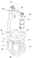
도 1은 본 발명에 따른 채수기를 도시한 개념도.
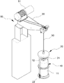
도 2는 본 발명에 따른 채수기를 또 다른 관점에서 도시한 개념도.
도 3은 본 발명에 따른 채수기 중 시료채취장치를 도시한 개념도.
도 4는 본 발명에 따른 채수기 중 시료채취장치의 하부를 도시한 개념도.
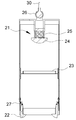
도 5는 본 발명에 따른 채수기 중 채수용기의 거치방법을 도시하기 위한 개념도.1 is a conceptual diagram showing a sowing machine according to the present invention;
FIG. 2 is a conceptual view showing a sowing machine according to the present invention from another viewpoint; FIG.
3 is a conceptual diagram showing a sample collecting apparatus in a sowing machine according to the present invention.
4 is a conceptual view showing a lower part of a sample collecting apparatus in a sowing machine according to the present invention.
5 is a conceptual view showing a method of mounting a water-collecting container during a sowing machine according to the present invention.
본 발명을 도 1 내지 5를 참고하여 상세히 설명하도록 한다. The present invention will be described in detail with reference to Figs.
도 1을 참고하면, 본 발명은 채수용기(10), 시료채취장치(20), 고정줄(30), 채수용기보관장치(40) 및 수심제어장치(50)를 포함한다. 이하 순차적으로 설명하도록 한다.Referring to FIG. 1, the present invention includes a
도 1, 2 및 5를 참고하여 채수용기(10)를 설명한다. 채수용기는 원통형으로 소정의 높이를 갖는 몸통(11) 및 내부로 채수가 가능하도록 형성된 입구(12)가 형성되어 있다. 도 1 등을 참고할 때, 채수용기(10)는 지름의 길이가 일정하고, 소정의 높이가 있는 것이 바람직하다. 유리 또는 플라스틱 등의 재질로 재작될 수 있다. 채수용기(10)는 후술하는 시료채취장치(20)에 홀딩되어, 수중으로 내려갈 수 있도록 하였다. 한편, 채수된 채수용기(10)는 후술하는 채수용기보관장치(40)에 보관될 수 있다. The
도 1 내지 5를 참고하여 시료채취장치(20)에 대하여 설명한다. 시료채취장치(20)는 채수용기(10)의 입구(12)를 개폐하기 위한 자동개폐기(21) 및 채수용기의 하부를 지지하기 위한 채수용기홀더(22) 등을 포함한다.The
도 3을 참고하면, 시료채취장치(20)는 자동개폐기(21) 및 채수용기홀더(22) 뿐만 아니라, 보조홀더(23), 고무마개(24), 스프링(25) 및 고정줄 홀더(26) 등을 더 포함한다.3, the
도 3을 참고하면, 자동개폐기(21)는 고정줄(30)의 내부에 마련된 신호선 및 전력선(미도시)에 의하여 전기적 신호 등을 인가받아 고무마개(24)의 승강 및 하강을 제어할 수 있도록 하였다. 즉, 신호선 및 전력선 등을 통하여 외부로부터 신호를 인가받아 고무마개(24)가 승강되어, 전술한 채수용기(10)의 입구(12)를 개폐시킬 수 있다. 고무마개(24)의 승강을 효율적으로 하여 입구(12)의 개폐를 정밀하게 하기 위하여 고무마개(24)의 일측에는 스프링(25)이 구비될 수 있다. 3, the
도 3을 참고하면, 고정줄(30)은 시료채취장치(20)의 상부측에 별도 마련된 고정줄홀더(26)에 의하여 고정된다. 고정줄홀더(26)는 컵형태로 되어 있어, 고정줄(30)이 고정되되, 회전가능하도록 한 구조를 채택하는 것이 바람직하다. 회전을 용이하게 함으로써 보다 편리한 위치제어가 가능해지기 때문이다. Referring to FIG. 3, the
도 3을 참고하면, 시료채취장치(20)의 중간부분에는 보조홀더(23)가 추가적으로 구비될 수 있다. 보조홀더(23)는 상측부로 돌출형성될 수 있으며, 이에 따라 시료채취장치(20)의 외주면을 가이드해주는 역할을 수행할 수 있다. Referring to FIG. 3, an
도 3을 참고하면, 시료채취장치(20)의 하부에는 채수용기홀더(22)가 마련되어 있다. 채수용기홀더(22)는 후술되는 채수용기홀더확장용돌기(42)에 의하여 외측으로 벌어질 수 있는 구조를 채택하고 있다. 채수용기홀더확장용돌기(42)에 의하여 외측으로 벌어진 채수용기홀더(22)는 복원력에 의하여 원위치될 수 있도록 복원스프링(27)이 구비되어 있다. Referring to FIG. 3, a
도 5를 참고하면, 시료채취장치(20)에 홀딩된 채수용기(10)는 적어도 하나의 채수용기(10)가 거치될 수 있는 채수용기보관장치(40)에 보관될 수 있다. 채수용기보관장치(40)에 채수용기(10)를 보관시키기 위하여, 시료채취장치(20)에 홀딩된 채수용기(10)가 채수용기보관장치(40) 속으로 삽입된다. 채수용기보관장치(40)에 구비된 채수용기홀더확장용돌기(42)는 시료채취장치(20)의 하부에 삽입된다. 이에 의하여 채수용기홀더(22)가 벌어지게되며, 자중에 의하여 채수용기(10)가 채수용기보관장치(40)의 하부플레이트(41)방향으로 낙하되어, 거치될 수 있다.5, the
도 1을 참고하여 고정줄(30)을 설명한다. 전술한 바와 같이 고정줄(30)의 일측은 고정줄홀더(26)와 결합되어 시료채취장치(20)를 고정하며, 타측은 후술되는 수심제어장치(50)에 고정된다. 수심제어장치(50)에 마련된 윈치 어셈블리(51)에 의하여 견인됨으로써, 시료채취장치(20)가 수중으로 내려가는 정도를 조절할 수 있다. The
도 1 등에 도시되지는 않았으나, 전술한 바와 같이 고정줄(30)은 신호선과 전력선이 내장될 수 있다. 신호선 및 전력선은 자동개폐기(21) 바람직하게는 솔레노이드 자동개폐기를 제어하는데 활용될 수 있다.Although not shown in FIG. 1 or the like, the
도 1을 참고하여 채수용기보관장치(40)에 대하여 설명한다. The water
채수용기보관장치(40)는 하부플레이트(41), 채수용기홀더확장용돌기(42), 상부플레이트(44), 인입홀(44) 등을 포함한다. 하부플레이트(41) 및 상부플레이트(44)를 상호 연결시키기 위한 지주(45)가 구비된다.The water collection
도 1을 참고하면, 채수용기보관장치(40)는 채수된 적어도 하나의 채수용기(10)를 거치시키기 위한 것이다. 채수용기보관장치(40)는 전술한 바와 같인 채수용기홀더확장용돌기(42)가 상측으로 돌출형성된 하부플레이트(41)가 구비된다. 하부플레이트(41)의 상측으로 다수개의 지주(45)가 구비되며, 지주(45)의 타측에 상부 플레이트(43)가 구비된다. 상부 플레이트(43)는 시료채취장치(20)가 인입될 수 있도록 인입홀(44)이 구비된다. Referring to FIG. 1, the water
도 1에 구체적으로 도시되지 않았으나, 채수용기보관장치는 베이스(46)를 바닥으로 하여 회전가능할 수 있는 회전축이 구비될 수 있다.Although not shown in detail in FIG. 1, the water tank storage apparatus may be provided with a rotating shaft which can rotate with the base 46 as a bottom.
마찬가지로, 각각의 채수용기(10) 마다 어떤 수심에서 채취되었는지 등을 기록할 수 있는 인덱스(미도시)가 구비될 수 있다. 인덱스는 후술되는 수심제어장치(50)와의 연동을 통하여 기록될 수 있다. Similarly, an index (not shown) can be provided to record the water depth of each water-collecting
채수용기보관장치(40) 중 각각의 보관홀 즉, 어느 하나의 채수용기홀더확장용돌기(42) 내측으로 인입된 채수용기(10)는 수심제어장치(50), 인덱스(미도시) 및 채수용기홀더확장용돌기(42) 등에 설치된 센서 등에 의하여 각각 인덱스 등에 메모리될 수 있다.Each of the storage holes of the water
도 1을 참고하면, 수심제어장치(50)는 윈치어셈블리(51)를 포함한다. 윈치어셈블리(51)의 일측에 고정줄(30)이 권취되어 있다. 윈치어셈블리(51)의 회전에 의하여 고정줄(30)이 권취된다. 풀릴경우 시료채취장치(20) 등의 자중에 의하여 수중으로 하강된다. 하강된 정도는 윈치어셈블리(51)의 회전수 등을 감지하여 체크될 수 있으며, 이에 따라 어느 정도의 수심에 시료채취장치(20)가 위치되고 있는지 감지될 수 있다. 수심제어장치(50)는 본 발명에 중요한 부분을 차지하는 부분이 아니므로 구체적인 설명은 생략한다.Referring to FIG. 1, the water
10 : 채수용기 20 : 시료채취장치
30 : 고정줄 40 : 채수용기보관장치
50 : 수심제어장치10: Collection vessel 20: Sampling device
30: fixed line 40: water tank storage device
50: Depth control device
Claims (4)
상기 고정줄(30)의 내부에는 신호선과 전력선이 내장되어 있으며,
상기 시료채취장치(20)의 상측부에는 상기 채수용기(10)의 입구(12)를 외부 신호에 의하여 개폐시킬 수 있는 자동개폐기(21);를 더 포함하는 것을 특징으로 하는 채수기.
(10) having a cylindrical body (11) and having an inlet (12) through which water can flow into an upper side; And a sample collection device (20) for supporting the water collection container (10) and hanging by a fixing line (30) on an upper side; In the watering machine,
A signal line and a power line are built in the fixed line 30,
Further comprising an automatic switch (21) for opening / closing the inlet (12) of the water collection container (10) by an external signal at an upper portion of the sample collection device (20).
적어도 하나의 채수용기(10)를 보관하기 위하여, 상측부로 돌출형성된 채수용기홀더확장용돌기(42)를 포함하는 하부플레이트(41); 및 시료채취장치(20)가 인입되는 적어도 하나의 인입홀(44)을 포함하는 상부플레이트(43)를 포함하는 채수용기보관장치(40)를 더 포함하며,
상기 시료채취장치(20)의 하부에는 상기 채수용기(10)의 하부를 지지하기 위한 채수용기홀더(22)를 더 포함하는 것을 특징으로 하는 채수기.
The method according to claim 1,
A lower plate (41) including a water collection container holder extension projection (42) protruding from the upper part to store at least one water collection container (10); And a top plate (43) including at least one inlet hole (44) through which the sampling device (20) is drawn,
Further comprising a water collection container holder (22) for supporting a lower portion of the water collection container (10) at a lower portion of the sample collection device (20).
상기 시료채취장치(20)가 상기 인입홀(44)로 삽입된 후, 상기 시료채취장치(20)의 하부에 마련된 상기 채수용기홀더(22)는 상기 채수용기홀더확장용돌기(42)가 상기 시료채취장치(20)의 내측으로 삽입되면서 외측으로 벌어짐에 따라 상기 채수용기(10)가 상기 하부플레이트(41)에 놓이는 것을 특징으로 하는 채수기.
3. The method of claim 2,
After the sampling device 20 is inserted into the inlet hole 44, the water collection container holder 22 provided at the lower part of the sample collection device 20 has the water collection container holder extension protrusion 42, Wherein the water collecting container (10) is placed on the lower plate (41) as it is inserted into the sample collecting device (20) and spreads outwardly.
상기 고정줄은 상기 고정줄(30)의 권취 여부를 결정하여 상기 시료채취장치(20)가 위치될 수심을 제어하기 위한 수심제어장치(50)를 더 포함하는 것을 특징으로 하는 채수기.The method according to claim 1,
Further comprising a water depth control device (50) for controlling the water depth at which the sample collection device (20) is to be positioned by determining whether or not the fixed line (30) is wound.
Priority Applications (1)
| Application Number | Priority Date | Filing Date | Title |
|---|---|---|---|
| KR1020170161811A KR102052467B1 (en) | 2017-11-29 | 2017-11-29 | Water sampler |
Applications Claiming Priority (1)
| Application Number | Priority Date | Filing Date | Title |
|---|---|---|---|
| KR1020170161811A KR102052467B1 (en) | 2017-11-29 | 2017-11-29 | Water sampler |
Publications (2)
| Publication Number | Publication Date |
|---|---|
| KR20190063039A true KR20190063039A (en) | 2019-06-07 |
| KR102052467B1 KR102052467B1 (en) | 2019-12-05 |
Family
ID=66850164
Family Applications (1)
| Application Number | Title | Priority Date | Filing Date |
|---|---|---|---|
| KR1020170161811A KR102052467B1 (en) | 2017-11-29 | 2017-11-29 | Water sampler |
Country Status (1)
| Country | Link |
|---|---|
| KR (1) | KR102052467B1 (en) |
Cited By (6)
| Publication number | Priority date | Publication date | Assignee | Title |
|---|---|---|---|---|
| CN110095313A (en) * | 2019-06-18 | 2019-08-06 | 浙江海洋大学 | A kind of the multidraw device and its sampling method of the water and sediment for coastal waters |
| CN111650001A (en) * | 2020-05-20 | 2020-09-11 | 深圳市国艺园林建设有限公司 | Water quality layered sampling system and control method |
| KR102211839B1 (en) * | 2020-08-24 | 2021-02-03 | (주)청담이엠텍 | Auto water sampler apparatus |
| CN112504763A (en) * | 2020-12-15 | 2021-03-16 | 自然资源部第一海洋研究所 | Seawater sampling device based on different depths |
| WO2022021594A1 (en) * | 2020-07-31 | 2022-02-03 | 力合科技(湖南)股份有限公司 | Automatic sampling device |
| CN114847214A (en) * | 2022-05-12 | 2022-08-05 | 何庭 | Land-based controllable breeding device and breeding method |
Citations (5)
| Publication number | Priority date | Publication date | Assignee | Title |
|---|---|---|---|---|
| JP3191974B2 (en) * | 1992-03-24 | 2001-07-23 | 前田建設工業株式会社 | Surface structure of the ground in indoor sports facilities |
| JP2007113982A (en) * | 2005-10-19 | 2007-05-10 | Dkk Toa Corp | Water sampler |
| KR100957808B1 (en) | 2007-12-13 | 2010-05-13 | (주)에코션 | Water sampler |
| JP2010189873A (en) * | 2009-02-16 | 2010-09-02 | Central Res Inst Of Electric Power Ind | Water sampler |
| KR101480790B1 (en) * | 2014-07-16 | 2015-01-16 | 주식회사 지오뷰 | Semi-automated open and close fluid mud sampler |
-
2017
- 2017-11-29 KR KR1020170161811A patent/KR102052467B1/en active IP Right Grant
Patent Citations (5)
| Publication number | Priority date | Publication date | Assignee | Title |
|---|---|---|---|---|
| JP3191974B2 (en) * | 1992-03-24 | 2001-07-23 | 前田建設工業株式会社 | Surface structure of the ground in indoor sports facilities |
| JP2007113982A (en) * | 2005-10-19 | 2007-05-10 | Dkk Toa Corp | Water sampler |
| KR100957808B1 (en) | 2007-12-13 | 2010-05-13 | (주)에코션 | Water sampler |
| JP2010189873A (en) * | 2009-02-16 | 2010-09-02 | Central Res Inst Of Electric Power Ind | Water sampler |
| KR101480790B1 (en) * | 2014-07-16 | 2015-01-16 | 주식회사 지오뷰 | Semi-automated open and close fluid mud sampler |
Cited By (7)
| Publication number | Priority date | Publication date | Assignee | Title |
|---|---|---|---|---|
| CN110095313A (en) * | 2019-06-18 | 2019-08-06 | 浙江海洋大学 | A kind of the multidraw device and its sampling method of the water and sediment for coastal waters |
| CN110095313B (en) * | 2019-06-18 | 2024-01-30 | 浙江海洋大学 | Multi-point sampling device for offshore water quality and sediment and sampling method thereof |
| CN111650001A (en) * | 2020-05-20 | 2020-09-11 | 深圳市国艺园林建设有限公司 | Water quality layered sampling system and control method |
| WO2022021594A1 (en) * | 2020-07-31 | 2022-02-03 | 力合科技(湖南)股份有限公司 | Automatic sampling device |
| KR102211839B1 (en) * | 2020-08-24 | 2021-02-03 | (주)청담이엠텍 | Auto water sampler apparatus |
| CN112504763A (en) * | 2020-12-15 | 2021-03-16 | 自然资源部第一海洋研究所 | Seawater sampling device based on different depths |
| CN114847214A (en) * | 2022-05-12 | 2022-08-05 | 何庭 | Land-based controllable breeding device and breeding method |
Also Published As
| Publication number | Publication date |
|---|---|
| KR102052467B1 (en) | 2019-12-05 |
Similar Documents
| Publication | Publication Date | Title |
|---|---|---|
| KR20190063039A (en) | Water sampler | |
| KR101806206B1 (en) | A Press-type Water Sampler | |
| KR20200082429A (en) | Apparatus for measuring quality of water | |
| US5473952A (en) | Benthic flux sampling device | |
| CN217819497U (en) | Based on groundwater detection test is with layering sampling device | |
| CN204649487U (en) | A kind of multi-level fluid sampling device | |
| US20040173035A1 (en) | Dual-opening sample containers, fluid sampling device and method of using same | |
| CN108106882A (en) | A kind of floating-board type sampler and application process | |
| CN208607036U (en) | Acquisition device | |
| CN207798481U (en) | A kind of multi-sensor sampler fixing depth device | |
| US4172385A (en) | Sampling device for septic tanks | |
| CN203587385U (en) | Special oil sampler | |
| CN212254765U (en) | Novel runoff sediment sampling device | |
| CN215640396U (en) | Petroleum sampler | |
| CN212432640U (en) | Portable water sample collection system | |
| CN107389382A (en) | A kind of methane-generating pit piston self-closing sampler | |
| CN212275296U (en) | A sewage sampling device for sewage detection | |
| RU164451U1 (en) | SEDIMENTATION TRAP | |
| CN210923175U (en) | Underground water layered sampling device for straight-through well pipe | |
| CN210604009U (en) | Micro-disturbance constant-depth underground water collecting and water level measuring device | |
| CN110823638A (en) | Surface layer water body sampling device for water quality detection and use method | |
| CN110849668A (en) | Surface water body sampling device for water quality detection | |
| CN214584218U (en) | Pool waste water sampler | |
| CN213397741U (en) | Novel water sampler capable of being automatically opened and closed at fixed depth | |
| CN108354632A (en) | A kind of piston self-closing gastric juice sampler |
Legal Events
| Date | Code | Title | Description |
|---|---|---|---|
| A201 | Request for examination | ||
| E902 | Notification of reason for refusal | ||
| E701 | Decision to grant or registration of patent right |