KR20190049860A - Remote control module for equipment - Google Patents
Remote control module for equipment Download PDFInfo
- Publication number
- KR20190049860A KR20190049860A KR1020197010841A KR20197010841A KR20190049860A KR 20190049860 A KR20190049860 A KR 20190049860A KR 1020197010841 A KR1020197010841 A KR 1020197010841A KR 20197010841 A KR20197010841 A KR 20197010841A KR 20190049860 A KR20190049860 A KR 20190049860A
- Authority
- KR
- South Korea
- Prior art keywords
- stimulation
- controller
- sterilization zone
- monitoring system
- stimulus
- Prior art date
Links
Images


Classifications
-
- A—HUMAN NECESSITIES
- A61—MEDICAL OR VETERINARY SCIENCE; HYGIENE
- A61B—DIAGNOSIS; SURGERY; IDENTIFICATION
- A61B5/00—Measuring for diagnostic purposes; Identification of persons
- A61B5/24—Detecting, measuring or recording bioelectric or biomagnetic signals of the body or parts thereof
-
- A61B5/04001—
-
- A61B5/04886—
-
- A—HUMAN NECESSITIES
- A61—MEDICAL OR VETERINARY SCIENCE; HYGIENE
- A61B—DIAGNOSIS; SURGERY; IDENTIFICATION
- A61B5/00—Measuring for diagnostic purposes; Identification of persons
- A61B5/24—Detecting, measuring or recording bioelectric or biomagnetic signals of the body or parts thereof
- A61B5/316—Modalities, i.e. specific diagnostic methods
- A61B5/389—Electromyography [EMG]
- A61B5/394—Electromyography [EMG] specially adapted for electroglottography or electropalatography
-
- A—HUMAN NECESSITIES
- A61—MEDICAL OR VETERINARY SCIENCE; HYGIENE
- A61B—DIAGNOSIS; SURGERY; IDENTIFICATION
- A61B5/00—Measuring for diagnostic purposes; Identification of persons
- A61B5/40—Detecting, measuring or recording for evaluating the nervous system
- A61B5/4029—Detecting, measuring or recording for evaluating the nervous system for evaluating the peripheral nervous systems
- A61B5/4035—Evaluating the autonomic nervous system
-
- A—HUMAN NECESSITIES
- A61—MEDICAL OR VETERINARY SCIENCE; HYGIENE
- A61B—DIAGNOSIS; SURGERY; IDENTIFICATION
- A61B5/00—Measuring for diagnostic purposes; Identification of persons
- A61B5/40—Detecting, measuring or recording for evaluating the nervous system
- A61B5/4029—Detecting, measuring or recording for evaluating the nervous system for evaluating the peripheral nervous systems
- A61B5/4041—Evaluating nerves condition
-
- A—HUMAN NECESSITIES
- A61—MEDICAL OR VETERINARY SCIENCE; HYGIENE
- A61B—DIAGNOSIS; SURGERY; IDENTIFICATION
- A61B5/00—Measuring for diagnostic purposes; Identification of persons
- A61B5/68—Arrangements of detecting, measuring or recording means, e.g. sensors, in relation to patient
- A61B5/6846—Arrangements of detecting, measuring or recording means, e.g. sensors, in relation to patient specially adapted to be brought in contact with an internal body part, i.e. invasive
- A61B5/6847—Arrangements of detecting, measuring or recording means, e.g. sensors, in relation to patient specially adapted to be brought in contact with an internal body part, i.e. invasive mounted on an invasive device
-
- A—HUMAN NECESSITIES
- A61—MEDICAL OR VETERINARY SCIENCE; HYGIENE
- A61B—DIAGNOSIS; SURGERY; IDENTIFICATION
- A61B5/00—Measuring for diagnostic purposes; Identification of persons
- A61B5/74—Details of notification to user or communication with user or patient ; user input means
- A61B5/7475—User input or interface means, e.g. keyboard, pointing device, joystick
-
- A—HUMAN NECESSITIES
- A61—MEDICAL OR VETERINARY SCIENCE; HYGIENE
- A61N—ELECTROTHERAPY; MAGNETOTHERAPY; RADIATION THERAPY; ULTRASOUND THERAPY
- A61N1/00—Electrotherapy; Circuits therefor
-
- A—HUMAN NECESSITIES
- A61—MEDICAL OR VETERINARY SCIENCE; HYGIENE
- A61N—ELECTROTHERAPY; MAGNETOTHERAPY; RADIATION THERAPY; ULTRASOUND THERAPY
- A61N1/00—Electrotherapy; Circuits therefor
- A61N1/18—Applying electric currents by contact electrodes
- A61N1/32—Applying electric currents by contact electrodes alternating or intermittent currents
- A61N1/36—Applying electric currents by contact electrodes alternating or intermittent currents for stimulation
- A61N1/36014—External stimulators, e.g. with patch electrodes
- A61N1/36017—External stimulators, e.g. with patch electrodes with leads or electrodes penetrating the skin
-
- A—HUMAN NECESSITIES
- A61—MEDICAL OR VETERINARY SCIENCE; HYGIENE
- A61B—DIAGNOSIS; SURGERY; IDENTIFICATION
- A61B18/00—Surgical instruments, devices or methods for transferring non-mechanical forms of energy to or from the body
- A61B18/04—Surgical instruments, devices or methods for transferring non-mechanical forms of energy to or from the body by heating
- A61B18/12—Surgical instruments, devices or methods for transferring non-mechanical forms of energy to or from the body by heating by passing a current through the tissue to be heated, e.g. high-frequency current
- A61B18/14—Probes or electrodes therefor
- A61B18/1442—Probes having pivoting end effectors, e.g. forceps
-
- A—HUMAN NECESSITIES
- A61—MEDICAL OR VETERINARY SCIENCE; HYGIENE
- A61B—DIAGNOSIS; SURGERY; IDENTIFICATION
- A61B18/00—Surgical instruments, devices or methods for transferring non-mechanical forms of energy to or from the body
- A61B2018/00636—Sensing and controlling the application of energy
- A61B2018/0066—Sensing and controlling the application of energy without feedback, i.e. open loop control
-
- A—HUMAN NECESSITIES
- A61—MEDICAL OR VETERINARY SCIENCE; HYGIENE
- A61B—DIAGNOSIS; SURGERY; IDENTIFICATION
- A61B18/00—Surgical instruments, devices or methods for transferring non-mechanical forms of energy to or from the body
- A61B2018/00636—Sensing and controlling the application of energy
- A61B2018/00773—Sensed parameters
- A61B2018/00839—Bioelectrical parameters, e.g. ECG, EEG
-
- A—HUMAN NECESSITIES
- A61—MEDICAL OR VETERINARY SCIENCE; HYGIENE
- A61B—DIAGNOSIS; SURGERY; IDENTIFICATION
- A61B18/00—Surgical instruments, devices or methods for transferring non-mechanical forms of energy to or from the body
- A61B2018/0091—Handpieces of the surgical instrument or device
-
- A—HUMAN NECESSITIES
- A61—MEDICAL OR VETERINARY SCIENCE; HYGIENE
- A61B—DIAGNOSIS; SURGERY; IDENTIFICATION
- A61B18/00—Surgical instruments, devices or methods for transferring non-mechanical forms of energy to or from the body
- A61B2018/0091—Handpieces of the surgical instrument or device
- A61B2018/00916—Handpieces of the surgical instrument or device with means for switching or controlling the main function of the instrument or device
- A61B2018/0094—Types of switches or controllers
-
- A—HUMAN NECESSITIES
- A61—MEDICAL OR VETERINARY SCIENCE; HYGIENE
- A61B—DIAGNOSIS; SURGERY; IDENTIFICATION
- A61B18/00—Surgical instruments, devices or methods for transferring non-mechanical forms of energy to or from the body
- A61B18/04—Surgical instruments, devices or methods for transferring non-mechanical forms of energy to or from the body by heating
- A61B18/12—Surgical instruments, devices or methods for transferring non-mechanical forms of energy to or from the body by heating by passing a current through the tissue to be heated, e.g. high-frequency current
- A61B18/14—Probes or electrodes therefor
- A61B18/1442—Probes having pivoting end effectors, e.g. forceps
- A61B2018/1452—Probes having pivoting end effectors, e.g. forceps including means for cutting
-
- A—HUMAN NECESSITIES
- A61—MEDICAL OR VETERINARY SCIENCE; HYGIENE
- A61B—DIAGNOSIS; SURGERY; IDENTIFICATION
- A61B18/00—Surgical instruments, devices or methods for transferring non-mechanical forms of energy to or from the body
- A61B18/04—Surgical instruments, devices or methods for transferring non-mechanical forms of energy to or from the body by heating
- A61B18/12—Surgical instruments, devices or methods for transferring non-mechanical forms of energy to or from the body by heating by passing a current through the tissue to be heated, e.g. high-frequency current
- A61B18/14—Probes or electrodes therefor
- A61B18/1442—Probes having pivoting end effectors, e.g. forceps
- A61B2018/146—Scissors
-
- A—HUMAN NECESSITIES
- A61—MEDICAL OR VETERINARY SCIENCE; HYGIENE
- A61B—DIAGNOSIS; SURGERY; IDENTIFICATION
- A61B2562/00—Details of sensors; Constructional details of sensor housings or probes; Accessories for sensors
- A61B2562/22—Arrangements of medical sensors with cables or leads; Connectors or couplings specifically adapted for medical sensors
- A61B2562/225—Connectors or couplings
-
- A—HUMAN NECESSITIES
- A61—MEDICAL OR VETERINARY SCIENCE; HYGIENE
- A61B—DIAGNOSIS; SURGERY; IDENTIFICATION
- A61B5/00—Measuring for diagnostic purposes; Identification of persons
- A61B5/48—Other medical applications
- A61B5/4887—Locating particular structures in or on the body
- A61B5/4893—Nerves
-
- A—HUMAN NECESSITIES
- A61—MEDICAL OR VETERINARY SCIENCE; HYGIENE
- A61B—DIAGNOSIS; SURGERY; IDENTIFICATION
- A61B5/00—Measuring for diagnostic purposes; Identification of persons
- A61B5/68—Arrangements of detecting, measuring or recording means, e.g. sensors, in relation to patient
- A61B5/6846—Arrangements of detecting, measuring or recording means, e.g. sensors, in relation to patient specially adapted to be brought in contact with an internal body part, i.e. invasive
- A61B5/6847—Arrangements of detecting, measuring or recording means, e.g. sensors, in relation to patient specially adapted to be brought in contact with an internal body part, i.e. invasive mounted on an invasive device
- A61B5/6852—Catheters
Abstract
모니터링 시스템은 모니터링 결과를 표시하기 위한 프로세서 및 디스플레이 시스템을 포함할 수 있다. 사용자는, 프로세서와 디스플레이 시스템 및 선택된 입력 장치로부터 이격된 멸균 영역에 있을 수 있다. 제어기는 사용자가 모니터링 시스템을 제어할 수 있도록 멸균 영역으로부터 모니터링 시스템에 물리적으로 연결될 수 있다.The monitoring system may include a processor and a display system for displaying the monitoring results. The user may be in a sterilization zone separate from the processor, the display system and the selected input device. The controller may be physically connected to the monitoring system from the sterilization area so that the user can control the monitoring system.

Description
본 개시내용은 신경 모니터링 시스템에 관한 것으로서, 특히 신경 모니터링 시스템의 원격 제어에 관한 것이다.The present disclosure relates to a neural monitoring system, and more particularly to a remote control of a neural monitoring system.
본 섹션은, 반드시 종래 기술은 아닌, 본 개시내용에 관련된 배경 정보를 제공한다.This section provides background information relating to this disclosure, not necessarily the prior art.
메드트로닉 사(Medtronic, Inc.)에서 판매하는 NIM-Response® 3.0 및/또는 NIM-Neuro® 3.0 신경 모니터링 시스템과 같은 신경 모니터링 시스템이, 근전도 검사(EMG) 반응을 모니터링하는데 사용될 수 있다. 특히, 모니터링 시스템은, 선택된 신경에서의 자극 및 자극의 위치로부터 멀리 떨어진 근육에서 감지되거나 또는 검출되는 반응을 제공할 수 있다. EMG 반응을 모니터링하는 것은 선택 절차 중에 하나 이상의 신경이 손상되었는지 여부를 결정하는 데 사용될 수 있다. 다양한 시스템에서, 모니터링 시스템은 절차 사용자 및 대상으로부터 떨어져 있는 모니터 사용자에 의해 제어될 수 있다. 따라서, 모니터 사용자는 절차 사용자에 의해 선택된 용도에 따라 모니터링 시스템을 조작하기 위해 절차 사용자로부터의 지시를 요구할 수 있다.Neural monitoring systems, such as the NIM-Response® 3.0 and / or the NIM-Neuro® 3.0 neurological monitoring system sold by Medtronic, Inc., can be used to monitor EMG responses. In particular, the monitoring system may provide a response that is sensed or detected in muscles away from the location of stimulation and stimulation in the selected nerve. Monitoring the EMG response can be used to determine whether one or more nerves are damaged during the selection procedure. In various systems, the monitoring system can be controlled by a monitor user who is away from the procedure user and the target. Thus, the monitor user may request an instruction from the procedural user to manipulate the monitoring system according to the application selected by the procedural user.
본 섹션은 본 개시내용의 일반적인 요약을 제공하는 것이며, 그 전체 범위 또는 그 모든 특징들의 포괄적인 개시내용은 아니다.This section is intended to provide a general summary of the present disclosure and is not a comprehensive disclosure of its full scope or all of its features.
신경 모니터링 시스템은 신경의 무결성을 모니터링하는 데 사용될 수 있다. 절차 중에, 절차 사용자는 절차 사용자에게 제공된 원격 제어 시스템을 사용하여 신경 감시 시스템의 동작을 조작 및/또는 변경할 수 있다. 원격 제어 시스템은 절차 사용자의 위치에서 절차 사용자에 의해 조작될 수 있는 하드웨어를 포함할 수 있다. 따라서, 신경 모니터링 시스템에 대한 지시 또는 제어는 모니터링 시스템으로부터 떨어진 위치에 제공될 수 있다.Neural monitoring systems can be used to monitor the integrity of neurons. During the procedure, the procedure user may manipulate and / or modify the operation of the neural surveillance system using the remote control system provided to the procedure user. The remote control system may include hardware that can be manipulated by the procedural user at the location of the procedural user. Thus, an indication or control to the neural monitoring system can be provided at a location remote from the monitoring system.
모니터링 시스템은 신경 모니터링으로부터 결과를 표시하기 위한 프로세서 및 디스플레이 시스템을 포함할 수 있다. 그러나, 모니터링 시스템은 멸균 영역에 배치하거나 대상의 근위에 배치하기 위해 즉시 사용할 수 없다. 대상은 선택된 절차에 대한 모니터링 시스템으로 모니터링될 수 있다. 절차 사용자는 외과 의사를 포함할 수 있다. 외과 의사는 선택된 절차에 대해 멸균 상태일 수 있다. 원격 제어 장치는 절차 중에 모니터링 및/또는 자극 기기에 연결될 수 있다. 원격 제어 장치는 외과 의사에게 연결되어 기기 및 모니터링 시스템과 상호 연결될 수도 있다. 원격 제어 장치는 멸균될 수 있고 멸균 영역에 배치하기에 적합할 수 있다.The monitoring system may include a processor and a display system for displaying results from neural monitoring. However, the monitoring system can not be used immediately to place in the sterile zone or to place it proximal to the subject. The object can be monitored with a monitoring system for the selected procedure. Procedure The user may include a surgeon. The surgeon may be sterile for the selected procedure. The remote control device may be connected to the monitoring and / or stimulation device during the procedure. The remote control device may be connected to the surgeon and interconnected with the instrument and the monitoring system. The remote control device may be sterilized and may be adapted for placement in a sterile zone.
원격 제어 장치는 일정 길이의 도전성 재료로 모니터링 시스템에 대한 물리적 연결을 포함한다. 물리적 연결은 와이어(예를 들어, 구리 또는 알루미늄 와이어), 도전성 중합체 또는 기타 적절한 도전성 재료를 포함할 수 있다. 물리적 연결은, 원격 시스템으로부터 모니터링 시스템으로의 신호가 모니터링 시스템과 상호 작용하는 것 및/또는 기기로부터 및/또는 기기로 신호를 전송하는 것 양자를 가능하게 할 수 있다.The remote control device comprises a physical connection to the monitoring system with a length of conductive material. The physical connection may comprise a wire (e. G., Copper or aluminum wire), a conductive polymer, or other suitable conductive material. The physical connection may enable both signals from the remote system to the monitoring system to interact with the monitoring system and / or to transmit signals from and / or to the device.
적용 가능한 추가적인 분야들이 본원에 제공되는 설명으로부터 명확하게 될 것이다. 본 요약에서의 설명 및 특정 예들은 예시만을 목적으로 의도된 것이고, 본 개시내용의 범위를 제한하도록 의도되지 않는다.Further areas of applicability will become apparent from the description provided herein. The description and specific examples in the present summary are intended for purposes of illustration only and are not intended to limit the scope of the disclosure.
본원에서 설명되는 도면들은 선택된 실시형태들의 예시적인 목적만을 위한 것이고, 모든 가능한 구현 예들을 위한 것은 아니며, 본 개시내용의 범위를 제한하는 것으로 의도되지 않는다.
도 1은 절차 중에 사용되는 자극 기기의 개략적인 환경도;
도 2는 기기로부터 분리된 원격 제어 장치의 상세도;
도 3은 원격 제어 장치의 커넥터의 상세도;
도 4는 대안적인 기기에 연결된 원격 제어 장치의 도면;
도 5는 기기와 연결된, 다양한 실시형태에 따른, 원격 제어 장치의 환경도; 및
도 6은 다양한 실시형태에 따른, 기기로부터 분리된 원격 제어 장치의 상세도이다.
대응하는 참조부호들은 여러 도면들에 걸쳐 대응하는 부분들을 나타낸다.The drawings described herein are for the illustrative purpose of selected embodiments only and are not intended to be limiting of the scope of the present disclosure for all possible implementations.
1 is a schematic environmental view of a stimulation instrument used during a procedure;
2 is a detailed view of the remote control device separated from the device;
3 is a detailed view of a connector of a remote control device;
4 is a diagram of a remote control device connected to an alternative device;
5 is an environmental view of a remote control device, in accordance with various embodiments, connected to the device; And
Figure 6 is a detailed view of a remote control device separate from the device, in accordance with various embodiments.
Corresponding reference characters indicate corresponding parts throughout the several views.
이제 예시적인 실시형태들이 첨부 도면들을 참조하여 보다 완전히 설명될 것이다.BRIEF DESCRIPTION OF THE DRAWINGS Exemplary embodiments will now be more fully described with reference to the accompanying drawings.
먼저 도 1을 참조하면, 미네소타 주 미니애폴리스에 사업장을 갖는 메드트로닉 사에 의해 판매되는 NIM® 신경 무결성 모니터링 시스템과 같은 모니터링 시스템(16)이 환경 설정에 도시되어 있다. 모니터링 시스템(16)은 디스플레이 스크린 또는 장치(22) 및 하나 이상의 입력 장치를 갖는 모니터 조립체(20)를 포함할 수 있다. 입력 장치는, 노브(24a), 터치 스크린(24b), 키보드(24c) 또는 다른 적절한 입력 장치 등의 정보의 명령을 입력하기 위한 하나 이상의 시스템 또는 구조체를 포함할 수 있다. 입력 장치는 다른 촉각 입력 장치, 오디오 입력 장치, 시각 입력 장치 등도 포함할 수 있다.Referring first to FIG. 1, a
모니터 조립체(20)는 프로세서(26) 및 메모리(28)를 더 포함할 수 있다. 프로세서(26)는 메모리(28)에 액세스하여 저장된 명령을 실행하거나 메모리(28) 상의 다른 데이터에 액세스할 수 있는 것으로 이해되어야 한다. 메모리(28)는 스피닝(spinning) 하드 디스크 드라이브, 솔리드 스테이트(solid state) 메모리 또는 다른 적절한 유형의 메모리와 같은 물리적 메모리를 포함할 수 있다. 또한, 메모리(28)는 모니터 조립체(20)에 통합되지 않을 수도 있지만, 통신 네트워크 등을 통해 프로세서(26)에 의해 액세스될 수 있다. 프로세서(26)는, 본원에 더 설명되는 바와 같이, 선택된 출력을 생성하는 명령을 실행하도록 동작 가능한 범용 프로세서일 수 있다. 프로세서(26)는 온보드(onboard) 메모리를 더 포함할 수 있다. 또한, 프로세서(26)는 주문형 집적 회로(ASIC)와 같은 특정 목적의 프로세서를 포함할 수 있다. 이에 따라, 프로세서(26)는, 비일시적 메모리일 수 있는 메모리(28)에 저장된 명령을 실행하여, 디스플레이 장치(22)에 표시용 출력을 제공할 수 있다.The
모니터링 시스템(20)은 자극부 및/또는 발생기를 더 포함할 수 있다. 자극부는 프로세서(26)에 의한 제어에 기초하여 전압을 생성하도록 구성될 수 있다. 프로세서(26)는 메모리(28)에 저장된 프로그램 및/또는 사용자(30)에 의한 제어의 명령을 실행할 수 있다. 본원에 논의되는 바와 같이, 모니터링 시스템(20)은 사용자(30)의 제어에 기초하여 자극 기기에서 또는 자극 기기로 자극을 생성하도록 동작될 수 있다.The
디스플레이 장치(22)에 표시된 정보는 사용자(30)에 의해 선택된 정보를 포함할 수 있다. 사용자(30)에 의해 행해지는 선택은 대상(34)에 관한 원하는 정보 또는 선택된 정보일 수 있다. 대상(34)은 인간 대상으로서 설명되지만, 대상은 인간이 아닌 대상을 포함하는 임의의 적절한 살아있는 대상일 수 있음이 이해되어야 한다. 또한, 모니터링 시스템(16)은 비생물 대상과 함께 사용될 수 있다. 비생물 대상은 전기적 활동과 같은 선택된 활동에 대해 모니터링되도록 선택된 시스템을 가질 수 있으며, 모니터링 시스템(16)이 사용될 수 있다. 그러나, 선택된 실시형태에서, 사용자(30)는 대상(34)에 대해 수술 절차를 행할 수 있다. 따라서, 사용자(30)는 근전도 검사(EMG) 반응을 모니터링함으로써 신경 반응 및/또는 무결성을 모니터링하도록 선택할 수 있다.The information displayed on the
하나 이상의 자극 또는 모니터링 조립체가 모니터링 시스템(16)에 통합되어 모니터 조립체(20)와 연결될 수 있다. 예를 들어, 갑상선 절제술 또는 다른 갑상선 수술과 같은 다양한 절차에서, 대상(30)의 반회 신경(RLN), 미주 신경 또는 다른 적절한 신경(36)을 모니터링하는 것이 선택될 수 있다. 다른 선택된 뇌신경 및/또는 척수 신경을 포함하여 다른 신경 또는 대안 신경도 모니터링될 수 있다. 반회신경(RLN)의 모니터링은 대상(34)의 선택된 부분과 접촉하는 하나 이상의 도전성 전극(40)을 가질 수 있는 신경 모니터링 식도 튜브(38)를 포함할 수 있다. 전극(40)은 튜브(38)의 외부에 부착될 수 있고 및/또는 튜브(38)의 구조에 통합될 수 있다. 전극(32)은 연결부(42)를 통해 모니터 조립체(20)에 연결될 수 있다.One or more stimulation or monitoring assemblies may be incorporated into the
추가적으로, 전극 조립체들과 같은, 주기적 자극 펄스들을 송신하거나 수신할 수 있는 전극을 포함하는 모니터 조립체(20)에 연결될 수 있다. 다양한 실시형태에서, 하나 이상의 자극 기기(50)가 사용될 수 있다. 자극 기기(50)는 커넥터(54)로 모니터 조립체(20)에 연결될 수 있다. 커넥터(54)는 자극 기기(50)와 모니터링 조립체(20) 사이의 물리적 연결을 허용할 수 있다. 커넥터(54)는 도전성 부재(예를 들어, 금속 와이어, 도전성 중합체 등)를 포함할 수 있다. 자극 기기(50)는 외과용 기기 등의 다양한 기기를 포함할 수 있다. 자극 기기의 예로는, 2015년 4월 3일자로 출원된 미국 특허 출원 제14/678,485호, 2015년 4월 3일자로 출원된 미국 특허 출원 제14/678,452호 - 양자는 모두 본원에 참조로서 포함된다 - 에 개시된 것을 포함한다.In addition, it may be connected to a
자극 기기(50)는 커넥터(54)로 모니터 조립체(20)와 연결되어 자극 신호를 대상(34)에게 송신 및/또는 수신하여, 신경 손상 또는 다른 조직 손상이 발생되었는지 또는 발생할 수 있는지를 결정하는 것을 돕는다. 메스와 같은 외과용 기기는 인간 외과 의사와 같은 사용자(30)에 의해 조작될 수 있다. 외과용 기기는 모니터 조립체(20)에 직접 연결될 수 없거나 직접 연결될 필요가 없을 수 있다. 그러나, 자극 기기(50)는 절개부(58) 등을 통해 대상(34)의 다양한 부분에 접근할 수 있다. 자극 기기(50)는, 신경 내의 반응 또는 자극 인가의 위치로부터 일정 거리에 위치된 위치에서의 EMG 반응을 자극하기 위해 신경(36) 또는 신경(36) 근처의 조직과 접촉하는데 사용될 수 있다.The stimulation device 50 is connected to the
모니터 조립체(20)는, 대상(34)에 대한 절차를 수행하면서 메스를 통한 상호 자극 또는 모니터링을 요구하지 않고, 자극 기기(50)를 통해 또는 이로부터의 신호를 모니터하도록 제공될 수 있다. 그러나, 당업자에게 이해되는 바와 같이, 다른 전극 조립체가 대상(34)에 연결될 수 있음이 이해되어야 한다. 대상(34)에 대한 자극은 하나 이상의 신경의 불응 기간을 설명할 수 있다.The
모니터링 시스템의 동작 및 모니터링 시스템(16)의 사용은, NIM-Response® 3.0 신경 모니터링 시스템을 포함하여, 메드트로닉 사에 의해 판매되는 NIM® 모니터링 시스템과 유사할 수 있다. 동작시에, 자극 기기(50)는, 본원에서 추가로 논의되는 바와 같이, 신경(36)과 접촉하거나 적어도 자극 연결되어 배치될 수 있으며, 신호는 모니터 시스템(20)으로부터 연결부(54)를 따라 전송될 수 있다. 튜브(38) 상의 전극(40)은 수신 전극일 수 있다. 그러나, 다른 수신 전극이 대상(34)과 연관 및/또는 접촉할 수 있음이 이해되어야 한다.The use of the monitoring system operation and
절차 동안, 사용자(30)는 신경(36)의 무결성 또는 연속성이 수술 절차 중에 손상되었는지 여부를 결정하도록 시도하거나 선택할 수 있다. 예를 들어, 다양한 절단 또는 조직 이동 절차가 신경(36)을 당기거나 손상시킬 수 있고, 신경(36)이 손상되지 않는다는 것을 보장하는 것이 선택될 수 있다. 따라서, 사용자(30)는 신경(36) 부근에 및/또는 신경(36)과 접촉하여 기기(50)를 위치시킬 수 있다. 모니터링 조립체(20)의 자극 시스템 또는 발생기를 포함하는 모니터링 시스템(16)은 조직(70)에서 반응을 일으키려고 시도하도록 자극 전압 및/또는 전류를 기기(50)를 통해 제공할 수 있다. 조직(70)은 유발된 반응에 따라 근육(70) 및/또는 성대와 같은 관련 조직의 움직임을 유발할 수 있는 근육을 포함할 수 있다. 상기 유발된 반응은 EMG 감지 전극(40)에 의해 감지될 수 있으며, 상기 신호는, 그래프, 경고, 음성 메시지(예를 들어, 유발된 EMG에 관해 수신되는 신호를 나타내는 톤) 등의, 사용자(30)에게 메시지의 표시를 허용하도록 상기 모니터링 조립체(20)에 전송될 수 있다. 사용자(30)는 원격 제어 장치(100)로 모니터링 조립체(20)를 제어할 수 있다.During the procedure, the
원격 제어 장치(100)는 기기(50)에 연결되는 것과 같은 다양한 실시형태에 따라 사용자(30)와 위치될 수 있다. 원격 제어 장치(100)는, 본원에 추가로 논의되는 바와 같이, 기기(50)에 제거 가능하게 연결될 수 있다. 원격 제어 장치(100)는 모니터링 시스템(16)을 사용하는 동안 모니터링 조립체(20)의 모든 기능 또는 특정 기능의 작동 또는 제어를 허용하는 스위치를 포함할 수 있다.The
모니터링 시스템(16)은 비 멸균 영역(110)으로부터 분리된 멸균 영역(104)에서 사용되도록 구성된 튜브 조립체(38) 및 기기(50)와 같은 특정 부분을 포함할 수 있다. 다양한 실시형태에 따르면, 물리적 구조는 수술실 또는 다른 선택된 위치에서 비 멸균 영역(110)으로부터 멸균 영역(104)을 분리하도록 배치될 수 있다. 그럼에도 불구하고, 키보드(24c)와 같은 다양한 입력을 포함하는 모니터링 조립체(20)는, 사용자(30)가 멸균 영역(104)에 있는 경우, 일반적으로 사용자(30)가 액세스할 수 없을 수도 있다. 사용자(30)는 모니터링 조립체(20)를 동작시키기 위해 비 멸균 영역(110) 내의 제2 사용자에게 명령을 제공하려고 시도할 수 있으며, 이는 비효율적일 수 있다. 따라서, 원격 제어 장치(100)는 사용자(30)가 멸균 영역(104) 밖으로 이동하지 않고 모니터링 조립체(20)의 적어도 일부 또는 특정 동작을 직접 제어하게 할 수 있다.The
멸균 영역(104) 내에서 사용자(30)에 의한 모니터링 조립체(20)의 제어는, 사용자(30)가 모니터링 시스템(16)의 동작에 관한 즉각적인 결정 및 구성 선택을 하도록 허용할 수 있다. 더욱이, 사용자(30)는 키보드(24c)와 같은 다른 입력 장치로부터 거리가 있을 수 있고, 원격 제어 장치(100)는 사용자(30)에 국부적으로(예를 들어, 팔의 길이 내에 또는 더 가까운 곳에) 있을 수 있다. 전술된 바와 같이, 모니터링 시스템(16)은 신경(36)을 통한 자극을 제공하여 근육(70)에서 반응을 일으킴으로써 신경(36)의 무결성을 결정하거나 확인하는데 사용될 수 있다. 따라서, 사용자(30)는 모니터링 시스템(16)의 사용 동안 모니터링 시스템(16)의 구성 또는 동작을 변경하기를 원할 수 있으며, 이는 구두 또는 다른 유형의 명령으로서 구성의 선택된 변경을 제2 사용자 또는 개인에게 전달하는 시도를 하지 않고 비 멸균 영역(110)에 위치된 모니터링 조립체(20)의 동작을 재구성하거나 변경하도록 시도한다.Control of the
당업자는, 모니터링 조립체(20)가 사용자(30) 근처의 비 멸균 영역(110)에 위치되더라도, 사용자(30)가 비 멸균 영역(110) 내의 아이템과 일반적으로 상호 작용할 수 없고 대상(34)에 대한 조작을 계속하기 위해 멸균 영역(104)에 즉시 복귀할 수 없음을 이해할 것이다. 따라서, 원격 제어 장치(100)를 멸균 영역(104)에 위치시킴으로써 사용자(30)는 멸균 영역(104)에서 원격 제어 장치(100)를 사용하여 모니터링 조립체(20)를 동작시킬 수 있다. 도전체(54)는 원격 제어 장치(100)로부터의 신호가 모니터링 조립체(20)로 운반되도록 하고 및/또는 모니터링 시스템(20)으로부터의 자극 신호가 기기(50)를 통해 신경(36)과 같은 환자(34)에게 전달되도록 한다.Those skilled in the art will appreciate that the
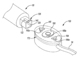
계속해서 도 1과 도 2 및 도 3을 추가로 참조하면, 원격 제어 장치(100)가 보다 상세히 논의될 것이다. 도 2 및 도 3에 보다 상세히 도시된 바와 같이, 원격 조작 장치(100)는 기기(50)에 제거 가능하게 연결될 수 있다. 그러나, 제어기(100)는 기기(50)에 견고하게 연결될 수 있다. 다양한 실시형태에서, 제어기(100)는, 기기(50)에 견고하게 연결될 때, 사용자(30)에 의해 기기로부터 분리될 때까지 기기(50)에 대해 이동되지 않을 것이다.With continuing reference to Figures 1, 2 and 3 further, the
견고한 연결을 보조하기 위해, 기기(50)는 외부 벽(122) 및 내부 벽(124)을 갖는 수형 커넥터(120)와 같은 연결부를 포함할 수 있다. 외부 벽(122)은 정사각형 형상과 같은 비 원형의 기하학적 구조를 가질 수 있다. 정사각형 형상은 기기(50)에 대한 제어기(100)의 회전에 저항하거나 제거하는 것을 보조할 수 있다. 도 3에 구체적으로 도시된 바와 같이, 원격 제어 장치(100)는 내부 벽(132)을 갖는 암형 커넥터(130)를 갖는 상대측 커넥터를 포함할 수 있다. 암형 커넥터(130)는 원격 제어 장치(100)의 하우징(136) 내에 오목부로서 형성될 수 있다. 하우징(136)은 암형 연결부(130)가 형성될 수 있는 외부 벽 또는 표면(138)을 포함할 수 있다. 수형 연결부(120) 및 암형 연결부(130)는 기기(50)와 원격 제어 장치(100) 사이에 물리적 및 견고한 연결을 형성할 수 있다. 따라서, 암형 커넥터(130)는 수형 커넥터(120)와 상보적인 형상을 가져서 회전 및 축방향의 견고한 연결을 유지하는데 보조할 수 있다. 그러나, 양자의 커넥터 부분이 둥근 형상인 경우와 같이 선택되면 회전이 허용될 수 있다.The device 50 may include a connection such as a
연결부(120, 130) 또는 다른 부분을 통해 전기적 또는 도전성 연결이 이루어질 수 있다. 예를 들어, 기기(50)는 내부 벽(124)과 함께 또는 내부 벽(124) 상에서, 암형 도전성 연결부(140)를 형성할 수 있다. 내부 벽(124)은, 양극성 또는 다극성 자극을 위한 다중 연결부를 제공하는 것과 같이, 기기(50)의 다양한 부분과 연결하기 위한 하나 이상의 도전체를 포함할 수 있다. 원격 제어 장치(100)는 암형 연결부(130) 내에 수형 도전성 커넥터(144)를 포함할 수 있다. 수형 도전성 커넥터(144)는 바나나 플러그 또는 클립과 같은 선택된 수형 연결부로서 형성될 수 있다. 수형 커넥터(144)는 기기(50) 상의 암형 커넥터(140)와 도전성 접속할 수 있다. 수형 커넥터(144)는 원격 제어 장치(100)를 모니터링 조립체(20)에 연결시키는 도전체(54)에 전기적으로 추가 연결될 수 있다. 도전체(54)는 원격 조립체(20)에 원격 제어 장치(100)의 물리적 연결을 허용한다. 따라서, 기기(50)는 모니터링 시스템(16)에서 사용자(30)에 의한 기기(50)의 동작을 허용하도록 원격 조립체(20)에 전기적 및 물리적으로 연결될 수 있다.Electrical or conductive connections may be made through the
원격 제어 장치(100)는 음성 입력, 물리적 입력 등을 포함하는 다양한 제어 옵션을 포함할 수 있다. 예를 들어, 원격 제어 장치(100)는 제1 푸시 버튼(160), 제2 푸시 버튼(164) 및 제3 푸시 버튼(168)과 같은 하나 이상의 푸시 버튼을 포함할 수 있다. 푸시 버튼들(160, 164, 및 168) 각각은, 버튼 아래에 위치되지만 하우징(136) 내에 위치되는 인쇄 회로 기판(PCB)(172) 상의 버튼과 관련된 각각의 스위치를 동작시키기 위해 하우징(136)에 대해 이동하는 물리적 버튼 또는 부재일 수 있다. PCB(172)는 각각의 버튼(160, 168, 164)에 대응하는 전기 스위치(160a, 168a, 164a)를 포함할 수 있다. PCB(172)는 스위치들(160a, 164a, 및 168a) 각각으로부터 도전체(54)까지의 전기적 연결부 또는 도전성 연결부를 포함할 수 있다. 따라서, 각 스위치(160a, 164a, 168a)로부터의 신호는 모니터링 조립체(20)로 전송되어 모니터링 조립체(20)를 제어 및/또는 동작시킬 수 있다. 기계적 토글 스위치, 터치 감지 부분(예를 들어, 용량성 표면), 조이스틱, 트랙볼, 롤러 버튼(예를 들어, 컴퓨터 마우스의 중앙 롤링 버튼) 등과 같은 다른 적절한 스위치가 제공될 수 있음이 이해되어야 한다.The
임의의 적절한 수의 입력 버튼 또는 부분이 원격 제어 장치(100)에 제공될 수 있음이 또한 이해되어야 한다. 따라서, 3개의 버튼(160, 164, 168)을 포함하는 것은 단지 예시적이다. 또한, 한번에 하나 이상의 버튼을 누르거나 동작시키는 것은 버튼(160, 164, 168) 중 임의의 하나를 개별적으로 누르는 것과 상이하고 구별되는 방식으로 모니터링 조립체(20)를 동작시킬 수 있다. 또한, 선택된 시간 내에(예를 들어, 제1 버튼의 2초 이내에 제1 버튼 및 제2 버튼을 누름) 순차적으로 버튼 중 하나를 조작 또는 누름으로써, 모니터링 조립체(20)를 더 다른 방식으로 동작시킬 수 있다.It should also be appreciated that any suitable number of input buttons or portions may be provided to the
다양한 실시형태에서, 모니터링 시스템(20)은 신경(36)에 자극을 제공하고 접촉부(40)를 통하는 것과 같이 근육(70) 등에서 유발 응답에 관한 신호를 수신하는데 사용될 수 있다. 따라서, 사용자(30)는, 수동으로 자극 펄스를 신경(36)에 제공하거나, 자극 펄스의 진폭을 변경하거나, 자극 펄스의 주파수를 변경하는 것 등을 위해 원격 제어 장치(100)를 동작시킬 수 있다. 다양한 실시형태에 따르면, 원격 제어 장치(100)는 자극 전류를 증가 및/또는 감소시키도록 동작될 수 있다. 예를 들어, 제1 버튼(160)은 자극 전류를 증가시키도록 동작되고, 제2 버튼(164)은 자극 전류를 감소시키도록 동작될 수 있다. 버튼들은 선택된 동작을 나타내는 시각 표시를 포함할 수 있다. 예를 들어, 제1 버튼(160)은 기기(50)를 향한 것과 같이 일반적으로 "위를" 향하는 화살표 또는 삼각형으로서 형성될 수 있다. 제2 버튼(164)은 동작의 감소를 나타내도록 보조하기 위해, 기기(50)로부터 떨어진 것과 같이 "아래를" 향하는 화살표 또는 삼각형과 같은 시각적 표시를 포함할 수 있다. 제3 버튼(168)은 메뉴 선택, 확인, 또는 모니터링 조립체(20)의 현재 동작을 전환하는데 사용될 수 있는 다른 일반적인 입력 등의 선택 버튼일 수 있다.In various embodiments, the
원격 제어 장치(100)는 모니터링 조립체(20)로부터의 음성 출력 또는 메시지를 증가 또는 감소시키도록 모니터링 조립체(20)를 제어하는데 사용될 수도 있다. 다시, 제1 버튼(160)은 볼륨을 증가시키기 위해 사용될 수 있는 반면 제2 버튼(164)은 볼륨을 감소시키는데 사용될 수 있다. 제3 버튼(168)은 자극 전류의 증가 및 감소 사이에서 모니터링 조립체(20)로부터의 메시지 볼륨을 증가 및 감소시키는 것과 같이 다양한 제어 가능한 옵션을 순환시키는데 사용될 수 있다.The
원격 제어 장치(100)는 모니터링 조립체(20)에 의해 수신되거나 표시되는 정보를 수집하거나 정보를 저장하기 위해 동작하도록 추가로 사용될 수 있다. 다시, 전술된 바와 같이, 전극(40)은 신경(36)의 자극으로 인해 유발된 반응을 수신할 수 있다. 유발된 응답은 디스플레이 장치(22) 상에 표시될 수 있거나 그렇지 않으면 사용자(30)에게 메시지로서 제공될 수 있다. 원격 제어 장치(100)는 모니터링 조립체(20)에 의해 현재 표시되거나 표현되는 정보의 스냅 샷(예를 들어, 스크린 샷)을 취득 또는 저장하도록 동작될 수 있다. 예를 들어, 디스플레이 장치(22)는 지각되거나 감지된 유발 응답에 관한 그래프를 표시할 수 있다. 취득하는 경우, 디스플레이 장치(22)의 스크린 샷은 사용자(30)가 전극(40)으로부터 모니터링 조립체(20)에 의해 수신된 선택된 신호를 저장할 수 있게 한다. 사용자(30)는 나중에 취득되거나 나중에 수신된 신호와의 비교를 위해 저장된 스크린 샷을 나중에 사용할 수 있다. 또한, 저장된 스크린 샷을 나중에 교육을 보조하는 데 사용할 수 있다.The
원격 제어 장치(100)는 또한 임계 한계를 설정하거나 제어하는데 사용될 수 있다. 임계 한계는 자극 전류 및/또는 전압과 관련될 수 있다. 또한, 임계 한계는 전극(40)에서 수신된 응답 또는 수신된 신호와 관련될 수 있다. 제어 임계 한계는 전극(40)에 의해 수신된 신호로서 식별된 파형에 대한 상한 또는 하한을 설정할 수 있다.The
원격 제어 장치(100)는 선택된 시스템을 조작하도록 추가로 조작될 수 있다. 예를 들어, 모니터링 조립체(20)는 연속 또는 자동 펄스 시스템으로 동작될 수 있다. 예를 들어, 자동 주기적 자극(메드트로닉 사에서 판매하는 APS® 자극 시스템)이 신경(36)과 연결될 수 있다. 원격 제어 장치(100)는 자동 주기적 자극 시스템을 통해 주기적 자극을 동작시키는데 사용될 수 있다. 예를 들어, 전극을 통해, 전술한 것과 유사하게, 자극 전류를 조절할 수 있다. 또한, APS® Monitoring System은 주기적 자극으로부터 베이스라인 유발 반응 및 베이스라인으로부터의 편차와 관련된 경보 조건을 결정하는 것과 같은 다양한 기능을 포함할 수 있다. 원격 제어 장치(100)는 베이스라인 결정(예를 들어, 베이스라인을 식별하기 위한 개시 및 종료 시간을 입력하고, 볼륨을 변경하고 및/또는 제시된 신호(유발 및 감지된 응답과 관련된 주기적인 톤)를 뮤트(mute)하며, 베이스라인으로부터의 편차에 관한 경보 조건을 변경하거나 또는 제어하고, APS® Monitoring System의 기타 적절한 기능) 동안 및/또는 베이스라인 결정을 개시하기 위해 모니터링 시스템(30)을 제어하는데 사용될 수 있다. 따라서, 원격 제어 장치는 모니터링 시스템(16) 내에서 모니터링 조립체(20)의 다양한 특징들을 동작시키는데 사용될 수 있다.The
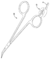
돌아가서 도 4를 참조하면, 원격 제어 장치(100)는 임의의 적절한 기기와 상호 연결될 수 있는 것이 이해되어야 한다. 예를 들어, 상기 기기는 자극 전극 집게(200)일 수 있으며, 상기 원격 제어 장치(100)의 암형 연결부(130)와 상호 연결되는 기기(50)의 수형 커넥터(120)와 유사한 연결부를 포함할 수 있다. 집게(200)는 신경(36) 및/또는 다른 조직 부분에서 또는 그 근처 등에서 대상(34)의 다양한 부분과 접촉하는 하나 이상의 접촉 전극을 포함할 수 있다.Referring back to FIG. 4, it should be understood that the
그럼에도 불구하고, 원격 제어 장치(100)는 단일 팁 프로브 또는 듀얼 팁 집게 또는 다른 적절한 기기와 같은 선택된 기기와 연결될 수 있다. 또한, 원격 제어 장치(100)는 제1 기기에 연결되고, 제1 기기(50)로부터 분리된 다음 제2 기기(500)에 연결될 수 있음이 이해되어야 한다. 그 후, 원격 제어 장치는 제2 기기(200)로부터 분리되어 제1 기기(50)에 재연결될 수 있다. 또한, 기기의 키트는 임의의 적절한 수의 기기를 포함할 수 있고, 원격 제어 장치(100)는 선택된 횟수만큼 다른 기기에 연결, 분리 및 재연결될 수 있다는 것이 이해되어야 한다.Nevertheless, the
원격 제어 장치(100)는 각각의 기기(50, 200)를 파지하는 동안 사용자(30)에 의한 원격 조작의 용이함을 위해 실질적으로 직접적으로 기기(50, 200)에 연결될 수 있다. 사용자(30)는 기기(50, 200) 및/또는 원격 제어 장치(100) 모두를 조작하기 위해 한 손 또는 양 손(30a, 30b)을 사용할 수 있다. 사용자(30)는 모니터링 조립체(20)를 제어하기 위해 버튼(160, 164, 168)과 같은 입력을 누르거나 조작하기 위해 한 손 또는 양 손의 손가락을 사용할 수 있다. 예를 들어, 제1 버튼(160)을 누르기 위해 단 하나의 손가락(예를 들어, 손의 손가락)만 사용될 수 있다. 위에서 언급했듯이, 제1 버튼을 누르면 자극 전류가 증가할 수 있다.The
그러나, 다양한 실시형태에 따르면, 도 5에 도시된 바와 같이, 원격 제어 장치(250)는 기기 연결 커넥터(260)를 포함하는, 커넥터(54)와 유사한 커넥터를 통해 연결될 수 있다. 기기 연결 커넥터(260)는 제2 연결부(264)에 연결되는 제1 연결부(262)를 포함할 수 있다. 제2 연결부(264)는 기기(270)에 연장되어 연결될 수 있다. 기기(270)는, 전술된 바와 같이, 기기(200)와 유사할 수도 있고, 또는 상술한 기기(50)와 유사할 수도 있다.5, the
커넥터(260)는 원격 제어 장치(250)가 기기(270)로부터 일정 거리에 위치되도록 한다. 예를 들어, 원격 제어 장치(250)는 클립(280)을 포함하는 것과 같은 홀더와 연결될 수 있다. 클립(280)은 원격 제어 장치(250)를 사용자(30)의 근처 또는 사용자(30)에, 및 환자(34)로부터 멀리 위치시키도록 멸균 드레이핑(예를 들어, 대상(34) 또는 대상(34) 근처의 부분 위에 배치됨) 또는 사용자(30)의 의복과 같은 선택부에 클리핑될 수 있다. 그 후, 사용자(30)는 손(30a, 30b) 중 하나 이상을 이동시켜 원격 제어 장치(250)를 동작시킬 수 있다.The
원격 제어 장치(250)는 원격 제어 장치(100)와 유사하거나 동일할 수 있으며, 제1 버튼(160), 제2 버튼(164) 및 제3 버튼(168)을 포함한다. 또한, 원격 제어 장치(250)는 전술한 것을 포함하는 임의의 적절한 입력부를 포함할 수 있다. 그럼에도 불구하고, 원격 제어 장치(250)는 사용자(30)에 의한 조작을 위해 편리하고 유리한 위치에 위치될 수 있다. 기기 커넥터(260)는 도전체(54)를 통해 비 멸균 영역(110) 내의 모니터링 조립체(20)에 연결될 수 있다. 기기 커넥터(260)는 도전체(54)와 상호 연결될 수 있고 및/또는 모니터링 조립체(20)에 직접 연결될 수 있다. 상기 기기 연결부(260)는 기기(270)로부터 멀리 떨어져 있는 선택된 위치에 원격 제어 장치(250)가 위치되는 것을 허용하도록 제공될 수 있다. 따라서, 원격 제어 장치(250)는 사용자(30)에 의한 조작을 위해 기기(270)로부터 멀리 위치될 수 있음이 이해되어야 한다. 그러나, 원격 제어 장치(100)는 사용자(30)에 의해 조작되도록 선택된 기기에 직접 접속될 수 있다.The
원격 제어 장치(250)는 도전체(260)와 함께 위치될 수 있다는 것이 추가로 이해되어야 한다. 원격 제어 장치(250)는 기기(200) 또는 기기(270)에 연결될 필요는 없지만, 도전체(260)에 연결된 분리된 도전체 상에 있을 필요는 없다. 따라서, 원격 제어 장치(250)는, 도전체(260)와 같이, 기기(270)로부터 거리를 두고 배치될 수 있지만, 이에 전기적으로 연결될 수 있다.It should further be understood that the
또한, 클립(280)은 원격 제어 장치(250)에 견고하게 연결될 필요는 없다. 예를 들어, 클립(280)은 도전체(260)에 연결될 수 있다. 그 후, 클립(280)은, 상술한 바와 같이, 외과 의사(30)와 같은 대상에 연결될 수 있으며, 도전체(260)는 외과 의사(30) 근처에서 원격 제어 장치(250)를 유지하는 것을 보조할 것이다. 따라서, 클립(280)은 원격 제어 장치(250)의 일부로서 형성될 필요는 없다.In addition, the
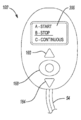
다양한 실시형태에 따르면, 디스플레이(300)가 원격 제어 장치(100) 또는 원격 제어 장치(250)에 포함될 수 있다. 예를 들어, 도 6에 도시된 바와 같이, 원격 제어 장치(100') 상의 디스플레이(300)는 외과 의사(30)에 의해 보여질 수 있다. 원격 제어 장치(100')는 스크린(300)의 추가를 제외하고는 원격 제어 장치(100)와 실질적으로 유사하거나 동일할 수 있다. 스크린(300)은 액정 디스플레이, 발광 다이오드 디스플레이 등과 같은 임의의 적절한 디스플레이일 수 있다. 디스플레이(300)는 또한 외과 의사(30)로부터의 직접 입력 및/또는 다른 스위치(160, 164 및 168)에 의해 변경될 수 있는 선택들의 디스플레이를 허용할 수 있다. 버튼(160, 164, 168)에 의해 다른 입력이 선택될 수 있는 반면, 직접 입력은 터치 감지 스크린에 의한 것일 수 있다.According to various embodiments, the
디스플레이(300)는, 모니터링 조립체(20)의 현재 동작과 같은, 외과 의사(30)에게 선택된 정보를 표시할 수 있다. 본 동작은 자극이 일어나고 있는지 여부, 자극의 유형, 자극 전류 또는 전압 등을 포함할 수 있다. 디스플레이(300)는 START, STOP, CONTINUOUS와 같은 제어 옵션을 표시하고, 자극을 증가시키며, 자극을 감소시킬 수도 있다.The
스크린(300)은, 상술한 것과 유사한 방식으로, 모니터링 조립체(20)를 동작시키기 위해 원격 제어 장치에서도 사용될 수 있다. 예를 들어, 선택된 유형의 동작이 외과 의사(30)에 의해 표시되거나 선택될 수 있다. 도 6에 도시된 바와 같이, 디스플레이는 자극의 중지와 관련된 "STOP" 또는 아이콘을 표시할 수 있고, STOP 아이콘은 밑줄에 의해, 사용자(30)에 의해 선택된 바와 같이, 강조 표시될 수 있다. 외과 의사(30)는, 버튼(160, 164, 168) 등으로, 터치 스크린 또는 선택부를 통해 STOP을 선택할 수 있다. 그 후, 시스템은 외과 의사(30)에 의해 선택된 바와 같이 동작할 수 있다. 따라서, 디스플레이(300)는 모니터링 조립체(20)를 제어하기 위해 원격 제어 장치(100') 단독으로 또는 다른 버튼과 조합하여 사용될 수 있다.The
디스플레이(300)는 프로세서(26)에 의해 저장되고 액세스되는 명령들에 기초하여 다양한 아이콘들 및 통신들을 표시할 수 있다. 예를 들어, 프로세서(26)는 자극을 개시하고 중지하라는 명령의 선택을 디스플레이(300)에 표시하기 위한 명령을 실행할 수 있다. 이어서, 사용자는 버튼(160) 등으로 원격 제어 장치(100')를 동작시켜, 표시된 아이콘 중 하나를 선택하거나 강조 표시할 수 있다(예를 들어, 디스플레이(300) 상에 밑줄이 표시된 상태로). 이어서, 사용자(30)는 버튼(168)을 누르는 것 등으로 강조 표시된 또는 선택된 아이콘을 선택함으로써 명령을 입력할 수 있다. 당업자에게 이해되는 바와 같이, 이러한 명령들은 선택된 알고리즘 및 명령에 통합될 수 있음이 이해되어야 한다.
다양한 실시형태에 따르면, 원격 제어 장치(100)와 같은 원격 제어 장치는 모니터링 조립체(20)와 통신하기 위해 도전체(54)에 물리적으로 연결될 필요는 없다. 전술된 바와 같이, 도전체(54)는 원격 제어 장치(100)로부터의 신호가 모니터링 조립체(20)에 전달되도록 하고 및/또는 모니터링 조립체(20)로부터의 자극 신호가 기기(50)를 통해 환자(34)에게, 예컨대 신경(36)에 전달되도록 하는 것을 허용한다. 그러나, 원격 제어 장치(100)는 모니터링 조립체(20)와 통신하기 위해 당업계에 일반적으로 공지된 바와 같은 무선 통신 시스템 또는 부분을 포함할 수 있다. 원격 제어 장치(100)는 전술된 바와 같이 동작될 수 있지만, 외과 의사(30)로부터의 지시는 무선 또는 공기(OTA; over the air) 전송으로 모니터링 조립체(20)에 통신될 수 있다. 또한, 모니터링 조립체(20)의 동작에 관한 모니터링 조립체(20)로부터의 전송은 원격 제어 장치(100)에 대한 무선 또는 OTA일 수 있다. 도전체(54) 또는 다른 선택된 도전체는, 자극을 전극에 제공하기 위해, 기구(200) 등의 선택된 기기에 연결될 수 있다. 모니터링 조립체(20)의 제어, 또는 적어도 선택된 제어는 모니터링 조립체(20)와 무선 통신하는 원격 제어 장치(100)에 의한 것일 수 있다.According to various embodiments, a remote control device, such as the
예시적인 실시형태들은 본 개시내용이 완전해지고 당업자들에게 그 범위를 충분히 전달하도록 제공된다. 특정 구성요소들, 장치들, 및 방법들의 예시와 같은 수많은 특정 세부사항들이 본 개시내용의 실시형태들의 철저한 이해를 제공하기 위해 언급된다. 당업자들에게는 특정 세부사항들이 채용될 필요가 없고, 예시적인 실시형태들이 많은 상이한 형태들로 구현될 수도 있으며, 어느 것도 본 개시내용의 범위를 제한하도록 해석되지 않아야 한다는 것이 명백할 것이다. 일부 예시적인 실시형태들에서, 널리 공지된 프로세스들, 널리 공지된 장치 구조들, 및 널리 공지된 기술들은 상세히 설명되지 않는다.The exemplary embodiments are provided so that this disclosure will be thorough and complete, and will fully convey the scope of the invention to those skilled in the art. Numerous specific details, such as examples of specific components, devices, and methods, are referred to in order to provide a thorough understanding of the embodiments of the present disclosure. It will be apparent to those skilled in the art that the specific details need not be employed and that the exemplary embodiments may be implemented in many different forms and that none should be construed as limiting the scope of the disclosure. In some exemplary embodiments, well known processes, well known device structures, and well-known techniques are not described in detail.
실시형태들의 전술한 설명은 예시 및 설명의 목적으로 제공되었다. 그것은 개시내용을 완전하게 하거나 또는 제한하는 것으로 의도되지 않는다. 특정 실시형태의 개별적인 요소들 또는 특징들은 일반적으로 특정 실시형태로 제한되지 않지만, 적용 가능한 경우, 상호교환 가능하도 심지어 구체적으로 도시되거나 또는 설명되지 않더라도, 선택된 실시형태에서 사용될 수 있다. 동일한 것이 많은 방식들에서 또한 변경될 수도 있다. 이러한 변형예들은 본 개시내용으로부터 벗어나는 것으로서 간주되지 않고, 모든 이러한 변형예들은 본 개시내용의 범위 내에 있도록 의도된다.The foregoing description of the embodiments has been presented for purposes of illustration and description. It is not intended to be exhaustive or to limit the disclosure. The individual elements or features of a particular embodiment are not generally limited to a particular embodiment, but may be used in selected embodiments, where applicable, interchangeably, even if not specifically shown or described. The same thing may also change in many ways. Such variations are not to be regarded as being departing from the present disclosure, and all such modifications are intended to be within the scope of the present disclosure.
Claims (22)
자극 전압을 생성하도록 구성된 자극 시스템;
환자 근처의 상기 멸균 영역 내에 위치되도록 구성된 자극 기기;
상기 자극 기기에 도전성으로 연결되고 환자 근처의 상기 멸균 영역 내에 위치되도록 구성된 제어기; 및
상기 자극 시스템과 상기 제어기에 물리적으로 연결된 도전체를 포함하고,
상기 제어기는 상기 자극 시스템의 적어도 하나의 동작을 제어하기 위한 입력부를 포함하는, 자극 모니터링 시스템.A stimulation monitoring system positioned in a non-sterile area outside the sterilization zone to stimulate at least a portion of the patient within the sterilization zone,
A stimulation system configured to generate a stimulation voltage;
A stimulation device configured to be positioned within the sterile zone near the patient;
A controller electrically connected to the stimulation device and configured to be located within the sterile area near the patient; And
And a conductor physically connected to the stimulation system and the controller,
Wherein the controller comprises an input for controlling at least one operation of the stimulation system.
상기 적어도 하나의 스위치는 상기 멸균 영역 내에서 사용자에 의해 조작되도록 구성되는, 자극 모니터링 시스템.The apparatus of claim 1, wherein the input includes at least one switch,
Wherein the at least one switch is configured to be operated by a user within the sterilization zone.
상기 푸시 버튼 스위치는 상기 하우징으로부터 연장되어 손가락에 의해 직접 디지트를 사용하여 결합되도록 구성된 제1 부분과, 상기 하우징 내에 배치된 인쇄 회로 기판에 고정되는 토글 스위치를 갖는 제2 부분을 포함하며,
상기 토글 스위치는 상기 자극 시스템에 전송되는 신호를 생성하도록 구성되고,
상기 자극 시스템은 상기 자극 시스템의 적어도 하나의 동작을 제어하기 위한 신호를 수신하도록 구성된 프로세서를 포함하는, 자극 모니터링 시스템.4. The apparatus of claim 3, wherein the controller includes an external housing,
Wherein the push button switch includes a first portion extending from the housing and configured to be coupled using a digit directly by a finger and a second portion having a toggle switch secured to a printed circuit board disposed within the housing,
Wherein the toggle switch is configured to generate a signal to be transmitted to the stimulation system,
Wherein the stimulation system comprises a processor configured to receive a signal for controlling at least one operation of the stimulation system.
상기 자극 시스템의 적어도 하나의 동작은, 자극 기간의 변경, 자극 전압의 변경, 자극의 개시, 자극의 중지, 스크린 샷의 캡쳐, 임계 한계의 제어, 또는 메시지 볼륨의 변경 중 적어도 하나를 포함하는, 자극 모니터링 시스템.The system according to any one of claims 1 to 4, wherein the stimulation system comprises a processor configured to receive a signal from an input for controlling at least one operation of the stimulation system,
Wherein at least one action of the stimulation system comprises at least one of altering a stimulation period, changing a stimulation voltage, initiating a stimulation, stopping stimulation, capturing a screen shot, controlling a threshold limit, Stimulation monitoring system.
상기 도전체는 상기 멸균 영역 내의 제어기로부터 상기 비 멸균 영역 내의 상기 자극 시스템으로 연장되는, 자극 모니터링 시스템.The controller according to any one of claims 1 to 5, wherein the controller has a housing firmly connected to the stimulation device,
Wherein the conductor extends from the controller in the sterilization zone to the stimulation system in the non-sterilization zone.
상기 디스플레이는 상기 자극 시스템의 현재 동작에 관한 정보 및/또는 사용자에 의해 입력되는 명령을 설명하도록 구성 가능한, 자극 모니터링 시스템.7. The apparatus of any one of claims 1 to 7, wherein the controller comprises a display,
Wherein the display is configurable to describe information about the current operation of the stimulation system and / or instructions entered by a user.
상기 자극 기기에 도전성으로 연결되고 환자 근처의 상기 멸균 영역 내에 위치되도록 구성된 제어기;
사용자에 의해 작동될 때 상기 자극 시스템에 신호를 송신하는 제어기로 형성되는 입력부; 및
상기 멸균 영역 내의 제어기와 상기 비 멸균 영역내의 상기 자극 시스템 사이의 연결 통신부를 포함하고,
상기 입력부로부터의 신호는 상기 자극 시스템의 적어도 하나의 동작을 제어하기 위한 것인, 자극 모니터링 시스템.A stimulation monitoring system having a stimulation system located in a non-sterile area outside a sterilization zone to stimulate at least a portion of the patient with a stimulation device within the sterilization zone,
A controller electrically connected to the stimulation device and configured to be located within the sterile area near the patient;
An input formed by a controller that transmits a signal to the stimulation system when actuated by a user; And
A connection communication unit between the controller in the sterilization zone and the stimulation system in the non-sterilization zone,
Wherein the signal from the input is for controlling at least one operation of the stimulus system.
상기 자극 기기는 환자 근처의 상기 멸균 영역 내에 위치되도록 구성된 자극 도전부를 가지며,
상기 제어기는 상기 자극 기기에 견고하게 연결되는, 자극 모니터링 시스템.The system of claim 9, wherein the stimulus system comprises a stimulus generator having a processor and configured to generate a stimulus current,
The stimulation device having a stimulation conductive portion configured to be positioned within the sterilization zone near the patient,
Wherein the controller is rigidly connected to the stimulation device.
상기 자극 기기는 환자 근처의 상기 멸균 영역 내에 위치되도록 구성된 자극 도전부를 가지며,
상기 제어기는 상기 멸균 영역 내의 상기 자극 기기로부터의 거리를 두고 도전체에 연결되고,
상기 도전체는 상기 제어기로부터 상기 자극 기기로 및 상기 제어기로부터 상기 자극 시스템으로 연장되는, 자극 모니터링 시스템.The system of claim 9, wherein the stimulus system comprises a stimulus generator having a processor and configured to generate a stimulus current,
The stimulation device having a stimulation conductive portion configured to be positioned within the sterilization zone near the patient,
The controller being connected to the conductors at a distance from the stimulation device in the sterilization zone,
The conductor extending from the controller to the stimulation device and from the controller to the stimulation system.
상기 적어도 하나의 스위치는 상기 멸균 영역 내에서 사용자에 의해 조작되도록 구성되는, 자극 모니터링 시스템.12. The apparatus of any one of claims 9 to 11, wherein the input comprises at least one switch,
Wherein the at least one switch is configured to be operated by a user within the sterilization zone.
상기 적어도 하나의 스위치는, 상기 하우징으로부터 연장되어 사용자의 손가락에 의해 직접 디지트를 사용하여 결합되도록 구성된 제1 부분과, 상기 하우징 내에 배치된 인쇄 회로 기판에 고정되는 토글 스위치를 갖는 제2 부분을 갖는 푸시 버튼 스위치를 포함하며,
상기 토글 스위치는 상기 자극 시스템에 전송되는 신호를 생성하도록 구성되고,
상기 자극 시스템은 상기 자극 시스템의 적어도 하나의 동작을 제어하기 위한 신호를 수신하도록 구성된 프로세서를 포함하는, 자극 모니터링 시스템.13. The system of claim 12, wherein the controller includes an external housing,
The at least one switch having a first portion extending from the housing and configured to be coupled using a digit directly by a user's finger and a second portion having a toggle switch secured to a printed circuit board disposed within the housing A push button switch,
Wherein the toggle switch is configured to generate a signal to be transmitted to the stimulation system,
Wherein the stimulation system comprises a processor configured to receive a signal for controlling at least one operation of the stimulation system.
상기 자극 시스템의 적어도 하나의 동작은, 자극 기간의 변경, 자극 전압의 변경, 자극의 개시, 자극의 중지, 스크린 샷의 캡쳐, 임계 한계의 제어, 또는 메시지 볼륨의 변경 중 적어도 하나를 포함하는, 자극 모니터링 시스템.The system of any one of claims 9 to 13, wherein the stimulus system includes a processor configured to receive a signal from the input,
Wherein at least one action of the stimulation system comprises at least one of altering a stimulation period, changing a stimulation voltage, initiating a stimulation, stopping stimulation, capturing a screen shot, controlling a threshold limit, Stimulation monitoring system.
멸균 영역 내에 상기 자극 기기를 위치시키는 단계;
상기 멸균 영역 외부의 비 멸균 영역 내에 상기 자극 시스템을 갖는 상기 자극 모니터링 시스템을 위치시키는 단계;
상기 멸균 영역 내의 상기 자극 기기에 제어기를 물리적으로 연결하는 단계;
상기 비 멸균 영역 내의 상기 자극 모니터링 시스템에 상기 제어기를 물리적으로 연결하는 단계; 및
상기 멸균 영역 내의 상기 제어기로 상기 자극 시스템의 적어도 하나의 동작을 제어하는 단계를 포함하는, 자극 모니터링 시스템을 제어하는 방법.A method of controlling a stimulus monitoring system having a stimulation system via a stimulation device,
Positioning the stimulation device within a sterile zone;
Positioning the stimulation monitoring system with the stimulation system within a non-sterile area outside the sterility area;
Physically connecting the controller to the stimulation device in the sterilization zone;
Physically connecting the controller to the stimulus monitoring system in the non-sterile area; And
And controlling at least one operation of the stimulation system with the controller within the sterilization zone.
상기 자극 시스템의 적어도 하나의 동작을 제어하는 단계는, 자극 기간의 변경, 자극 전압의 변경, 스크린 샷의 캡쳐, 임계 한계의 제어, 또는 메시지 볼륨의 변경 중 적어도 하나를 포함하는, 자극 모니터링 시스템을 제어하는 방법.21. The system of claim 20, wherein the stimulus system includes a processor configured to receive a signal from the controller,
Wherein controlling at least one operation of the stimulation system comprises at least one of altering a stimulation period, changing a stimulation voltage, capturing a screen shot, controlling a threshold limit, or changing a message volume. How to control.
Applications Claiming Priority (3)
| Application Number | Priority Date | Filing Date | Title |
|---|---|---|---|
| US15/269,051 US10849517B2 (en) | 2016-09-19 | 2016-09-19 | Remote control module for instruments |
| US15/269,051 | 2016-09-19 | ||
| PCT/US2017/051825 WO2018053295A1 (en) | 2016-09-19 | 2017-09-15 | Remote control module for instruments |
Publications (1)
| Publication Number | Publication Date |
|---|---|
| KR20190049860A true KR20190049860A (en) | 2019-05-09 |
Family
ID=60002012
Family Applications (1)
| Application Number | Title | Priority Date | Filing Date |
|---|---|---|---|
| KR1020197010841A KR20190049860A (en) | 2016-09-19 | 2017-09-15 | Remote control module for equipment |
Country Status (8)
| Country | Link |
|---|---|
| US (2) | US10849517B2 (en) |
| EP (1) | EP3515304A1 (en) |
| JP (1) | JP2019532704A (en) |
| KR (1) | KR20190049860A (en) |
| CN (1) | CN109963504A (en) |
| AU (1) | AU2017326105A1 (en) |
| CA (1) | CA3037298A1 (en) |
| WO (1) | WO2018053295A1 (en) |
Families Citing this family (5)
| Publication number | Priority date | Publication date | Assignee | Title |
|---|---|---|---|---|
| US9918669B2 (en) | 2014-08-08 | 2018-03-20 | Medtronic Xomed, Inc. | Wireless nerve integrity monitoring systems and devices |
| US10039915B2 (en) | 2015-04-03 | 2018-08-07 | Medtronic Xomed, Inc. | System and method for omni-directional bipolar stimulation of nerve tissue of a patient via a surgical tool |
| US20220257940A1 (en) | 2021-02-18 | 2022-08-18 | Medtronic Xomed, Inc. | System and Method for Stimulation of Nerve Tissue |
| US20220265245A1 (en) * | 2021-02-23 | 2022-08-25 | Bard Access Systems, Inc. | Computing Device Controller System |
| JP7421832B1 (en) | 2023-06-21 | 2024-01-25 | メディジェンス合同会社 | Stethoscope |
Family Cites Families (128)
| Publication number | Priority date | Publication date | Assignee | Title |
|---|---|---|---|---|
| DE2831313A1 (en) | 1978-07-17 | 1980-02-07 | Draegerwerk Ag | DEVICE FOR SUPPORTING BREATHING AND / OR ARTIFICIAL VENTILATION |
| SE9601387D0 (en) | 1996-04-12 | 1996-04-12 | Siemens Elema Ab | Device for monitoring measuring electrodes for recording physiological measurement signals and their leads |
| US6017354A (en) * | 1996-08-15 | 2000-01-25 | Stryker Corporation | Integrated system for powered surgical tools |
| US6029090A (en) | 1997-01-27 | 2000-02-22 | Herbst; Ewa | Multi-functional electrical stimulation system |
| US20030171747A1 (en) | 1999-01-25 | 2003-09-11 | Olympus Optical Co., Ltd. | Medical treatment instrument |
| US6496705B1 (en) | 2000-04-18 | 2002-12-17 | Motorola Inc. | Programmable wireless electrode system for medical monitoring |
| US6441747B1 (en) | 2000-04-18 | 2002-08-27 | Motorola, Inc. | Wireless system protocol for telemetry monitoring |
| US20050101878A1 (en) | 2001-04-18 | 2005-05-12 | Daly Christopher N. | Method and apparatus for measurement of evoked neural response |
| US11229472B2 (en) * | 2001-06-12 | 2022-01-25 | Cilag Gmbh International | Modular battery powered handheld surgical instrument with multiple magnetic position sensors |
| US6932816B2 (en) | 2002-02-19 | 2005-08-23 | Boston Scientific Scimed, Inc. | Apparatus for converting a clamp into an electrophysiology device |
| US7236822B2 (en) | 2002-03-22 | 2007-06-26 | Leptos Biomedical, Inc. | Wireless electric modulation of sympathetic nervous system |
| KR100632980B1 (en) | 2002-12-20 | 2006-10-11 | 마쯔시다덴기산교 가부시키가이샤 | Gate driver, motor driving device including the gate driver, and apparatus equipped with the motor driving device |
| US7216001B2 (en) | 2003-01-22 | 2007-05-08 | Medtronic Xomed, Inc. | Apparatus for intraoperative neural monitoring |
| US7689292B2 (en) | 2003-02-27 | 2010-03-30 | Macosta Medical U.S.A., L.L.C. | Nerve stimulation functionality indicator apparatus and method |
| CN2610843Y (en) | 2003-04-22 | 2004-04-14 | 上海诺诚电气有限公司 | Scalp impedance detector |
| US7129836B2 (en) | 2003-09-23 | 2006-10-31 | Ge Medical Systems Information Technologies, Inc. | Wireless subject monitoring system |
| US7496407B2 (en) | 2003-12-23 | 2009-02-24 | Odderson Ib R | Nerve stimulator measuring device |
| US7869881B2 (en) | 2003-12-24 | 2011-01-11 | Cardiac Pacemakers, Inc. | Baroreflex stimulator with integrated pressure sensor |
| US20050159659A1 (en) | 2004-01-16 | 2005-07-21 | Mohamad Sawan | Catheter for transdiaphragmatic pressure and diaphragm electromyogram recording using helicoidal electrodes |
| US7292886B1 (en) | 2004-01-20 | 2007-11-06 | Pacesetter, Inc. | Bifocal cardiac stimulation device and methods |
| US7359751B1 (en) * | 2004-05-05 | 2008-04-15 | Advanced Neuromodulation Systems, Inc. | Clinician programmer for use with trial stimulator |
| US20050267529A1 (en) | 2004-05-13 | 2005-12-01 | Heber Crockett | Devices, systems and methods for tissue repair |
| US20050261559A1 (en) | 2004-05-18 | 2005-11-24 | Mumford John R | Wireless physiological monitoring system |
| US10342452B2 (en) * | 2004-07-29 | 2019-07-09 | Medtronic Xomed, Inc. | Stimulator handpiece for an evoked potential monitoring system |
| WO2006026482A2 (en) | 2004-08-25 | 2006-03-09 | Encore Medical Asset Corporation | Chiropractic table with continuous passive motion |
| US9247952B2 (en) | 2004-10-15 | 2016-02-02 | Amendia, Inc. | Devices and methods for tissue access |
| EP1656883A1 (en) | 2004-11-10 | 2006-05-17 | Universite Libre De Bruxelles | Portable device for measuring EMG signal |
| EP2409641B1 (en) * | 2005-02-02 | 2017-07-05 | NuVasive, Inc. | System for performing neurophysiologic assessments during spine surgery |
| EP1850803B1 (en) | 2005-02-18 | 2014-03-26 | Zimmer, Inc. | Smart joint implant sensors |
| WO2006090371A2 (en) | 2005-02-22 | 2006-08-31 | Health-Smart Limited | Methods and systems for physiological and psycho-physiological monitoring and uses thereof |
| US7878981B2 (en) * | 2005-03-01 | 2011-02-01 | Checkpoint Surgical, Llc | Systems and methods for intra-operative stimulation |
| US10154792B2 (en) | 2005-03-01 | 2018-12-18 | Checkpoint Surgical, Inc. | Stimulation device adapter |
| US20060200023A1 (en) | 2005-03-04 | 2006-09-07 | Sdgi Holdings, Inc. | Instruments and methods for nerve monitoring in spinal surgical procedures |
| JP2008532713A (en) | 2005-03-18 | 2008-08-21 | ザ トラスティーズ オブ ザ スティーブンス インスティテュート オブ テクノロジー | Apparatus and method for diagnosing the cause of muscle pain |
| WO2006113394A2 (en) | 2005-04-15 | 2006-10-26 | Surgisense Corporation | Surgical instruments with sensors for detecting tissue properties, and systems using such instruments |
| US20060241725A1 (en) | 2005-04-25 | 2006-10-26 | Imad Libbus | Method and apparatus for simultaneously presenting cardiac and neural signals |
| US8068910B2 (en) | 2005-04-28 | 2011-11-29 | Medtronic, Inc. | Flexible tube sensor for sensing urinary sphincter pressure |
| US20060276702A1 (en) | 2005-06-03 | 2006-12-07 | Mcginnis William | Neurophysiological wireless bio-sensor |
| TW200704391A (en) | 2005-07-29 | 2007-02-01 | chang-an Zhou | Paste physical monitoring device, system and network |
| US8657814B2 (en) * | 2005-08-22 | 2014-02-25 | Medtronic Ablation Frontiers Llc | User interface for tissue ablation system |
| US8568317B1 (en) | 2005-09-27 | 2013-10-29 | Nuvasive, Inc. | System and methods for nerve monitoring |
| US8764654B2 (en) | 2008-03-19 | 2014-07-01 | Zin Technologies, Inc. | Data acquisition for modular biometric monitoring system |
| US7988688B2 (en) | 2006-09-21 | 2011-08-02 | Lockheed Martin Corporation | Miniature apparatus and method for optical stimulation of nerves and other animal tissue |
| US7993269B2 (en) | 2006-02-17 | 2011-08-09 | Medtronic, Inc. | Sensor and method for spinal monitoring |
| US20070282217A1 (en) | 2006-06-01 | 2007-12-06 | Mcginnis William J | Methods & systems for intraoperatively monitoring nerve & muscle frequency latency and amplitude |
| WO2008002917A2 (en) | 2006-06-27 | 2008-01-03 | Cyberkinetics Neurotechnology Systems, Inc. | Systems and methods for promoting nerve regeneration |
| US20100152811A1 (en) | 2006-06-30 | 2010-06-17 | Flaherty Christopher J | Nerve regeneration system and lead devices associated therewith |
| FI20065500A0 (en) | 2006-07-25 | 2006-07-25 | Mediracer Ltd | A method and apparatus for wirelessly controlling nerve response measurement |
| US20080071315A1 (en) | 2006-08-31 | 2008-03-20 | Tamara Colette Baynham | Integrated catheter and pulse generator systems and methods |
| US20100036280A1 (en) | 2006-09-08 | 2010-02-11 | Ull Meter A/S | Method of utilising measurements of threshold of pain |
| US7605738B2 (en) | 2006-09-13 | 2009-10-20 | Advantest Corporation | A-D converter and A-D convert method |
| US7789833B2 (en) | 2006-11-16 | 2010-09-07 | Penrith Corporation | Integrated nerve stimulator and ultrasound imaging device |
| WO2008097407A2 (en) | 2006-12-18 | 2008-08-14 | Trillium Precision Surgical, Inc. | Intraoperative tissue mapping and dissection systems, devices, methods, and kits |
| US8886280B2 (en) | 2007-01-23 | 2014-11-11 | The Magstim Company Limited | Nerve monitoring device |
| US20100145178A1 (en) | 2007-01-23 | 2010-06-10 | Kartush Jack M | Nerve monitoring device |
| US8374673B2 (en) | 2007-01-25 | 2013-02-12 | Warsaw Orthopedic, Inc. | Integrated surgical navigational and neuromonitoring system having automated surgical assistance and control |
| US7987001B2 (en) | 2007-01-25 | 2011-07-26 | Warsaw Orthopedic, Inc. | Surgical navigational and neuromonitoring instrument |
| JP4773377B2 (en) | 2007-01-29 | 2011-09-14 | ルネサスエレクトロニクス株式会社 | COMMUNICATION SYSTEM, COMMUNICATION DEVICE, AND FLOW CONTROL METHOD |
| WO2008124079A1 (en) * | 2007-04-03 | 2008-10-16 | Nuvasive, Inc. | Neurophysiologic monitoring system |
| US8594779B2 (en) | 2007-04-30 | 2013-11-26 | Medtronic, Inc. | Seizure prediction |
| KR100877229B1 (en) | 2007-05-14 | 2009-01-09 | 가천의과학대학교 산학협력단 | Neural electronic interface device for motor and sensory controls of human body |
| US8295933B2 (en) | 2007-05-30 | 2012-10-23 | Medtronic, Inc. | Implantable medical lead including voiding event sensor |
| US20080306348A1 (en) | 2007-06-06 | 2008-12-11 | National Yang-Ming University | Miniature wireless apparatus for recording physiological signals of humans and use thereof |
| US8680986B2 (en) | 2007-08-01 | 2014-03-25 | Peter Costantino | System and method for facial nerve monitoring during facial surgery |
| US8926509B2 (en) | 2007-08-24 | 2015-01-06 | Hmicro, Inc. | Wireless physiological sensor patches and systems |
| WO2009051965A1 (en) | 2007-10-14 | 2009-04-23 | Board Of Regents, The University Of Texas System | A wireless neural recording and stimulating system for pain management |
| US9084550B1 (en) | 2007-10-18 | 2015-07-21 | Innovative Surgical Solutions, Llc | Minimally invasive nerve monitoring device and method |
| US7974702B1 (en) | 2008-01-10 | 2011-07-05 | Pacesetter, Inc. | Communication device, communication system and communication method for an implantable medical device |
| US20090182322A1 (en) | 2008-01-11 | 2009-07-16 | Live Tissue Connect, Inc. | Bipolar modular forceps modular arms |
| US9078671B2 (en) | 2008-04-17 | 2015-07-14 | Warsaw Orthopedic, Inc. | Surgical tool |
| ES2642583T3 (en) * | 2008-04-17 | 2017-11-16 | C.R. Bard, Inc. | Systems for breaking a sterile field for intravascular placement of a catheter |
| US20090299439A1 (en) | 2008-06-02 | 2009-12-03 | Warsaw Orthopedic, Inc. | Method, system and tool for surgical procedures |
| US9119533B2 (en) | 2008-10-07 | 2015-09-01 | Mc10, Inc. | Systems, methods, and devices having stretchable integrated circuitry for sensing and delivering therapy |
| US8428733B2 (en) | 2008-10-16 | 2013-04-23 | Medtronic, Inc. | Stimulation electrode selection |
| CN102281816B (en) | 2008-11-20 | 2015-01-07 | 人体媒介公司 | Method and apparatus for determining critical care parameters |
| US8515520B2 (en) | 2008-12-08 | 2013-08-20 | Medtronic Xomed, Inc. | Nerve electrode |
| US9084551B2 (en) | 2008-12-08 | 2015-07-21 | Medtronic Xomed, Inc. | Method and system for monitoring a nerve |
| US20100160731A1 (en) | 2008-12-22 | 2010-06-24 | Marc Giovannini | Ultrasound-visualizable endoscopic access system |
| US8126736B2 (en) | 2009-01-23 | 2012-02-28 | Warsaw Orthopedic, Inc. | Methods and systems for diagnosing, treating, or tracking spinal disorders |
| US9370654B2 (en) | 2009-01-27 | 2016-06-21 | Medtronic, Inc. | High frequency stimulation to block laryngeal stimulation during vagal nerve stimulation |
| US8989855B2 (en) | 2009-01-30 | 2015-03-24 | Medtronic Xomed, Inc. | Nerve monitoring during electrosurgery |
| US20100280568A1 (en) | 2009-04-30 | 2010-11-04 | Cherik Bulkes | Implantable High Efficiency Energy Transfer Module With Near-Field Inductive Coupling |
| WO2011014598A1 (en) | 2009-07-29 | 2011-02-03 | Nexpath Medical S.A. | Neurophysiological stimulation system and methods with wireless instrumentation |
| US8233992B2 (en) | 2009-08-28 | 2012-07-31 | Boston Scientific Neuromodulation Corporation | Method and apparatus for determining relative positioning between neurostimulation leads |
| AU2010295275B2 (en) | 2009-09-21 | 2013-10-17 | Medtronic, Inc. | Waveforms for electrical stimulation therapy |
| CA2776163C (en) | 2009-10-02 | 2018-04-24 | Medtronic Xomed, Inc. | Endotracheal tube apparatus |
| US8753333B2 (en) | 2010-03-10 | 2014-06-17 | Covidien Lp | System for determining proximity relative to a nerve |
| US8568312B2 (en) | 2010-03-12 | 2013-10-29 | MaryRose Cusimano Reaston | Electro diagnostic functional assessment unit (EFA-3) |
| US10631912B2 (en) | 2010-04-30 | 2020-04-28 | Medtronic Xomed, Inc. | Interface module for use with nerve monitoring and electrosurgery |
| US20130030257A1 (en) | 2010-05-14 | 2013-01-31 | Kai Medical, Inc. | Systems and methods for non-contact multiparameter vital signs monitoring, apnea therapy, apnea diagnosis, and snore therapy |
| CA2801333C (en) | 2010-06-04 | 2018-11-20 | University Health Network | Functional electrical stimulation device and system, and use thereof |
| US9149188B2 (en) | 2010-07-01 | 2015-10-06 | Shenzhen Mindray Bio-Medical Electronics Co. Ltd. | Systems and methods for synchronizing data received from multiple sensor modules in a patient monitor system |
| CA2825550C (en) | 2011-03-24 | 2022-07-12 | California Institute Of Technology | Neurostimulator |
| WO2012151493A2 (en) | 2011-05-04 | 2012-11-08 | The University Of Akron | Variable-frequency stimulator for electrosurgery |
| CN104080509B (en) | 2011-07-29 | 2017-09-08 | 米克伦设备有限责任公司 | The remote control that power or polarity for nerve stimulator are selected |
| US9579503B2 (en) | 2011-10-05 | 2017-02-28 | Medtronic Xomed, Inc. | Interface module allowing delivery of tissue stimulation and electrosurgery through a common surgical instrument |
| US9855431B2 (en) | 2012-03-19 | 2018-01-02 | Cardiac Pacemakers, Inc. | Systems and methods for monitoring for nerve damage |
| US20150012066A1 (en) | 2012-03-22 | 2015-01-08 | Wendell Martin Underwood | Noninvasive delivery and control of stimulation signals |
| EP2833785A4 (en) | 2012-04-03 | 2015-10-28 | Altec Inc | Disposable low-profile conformable biomedical sensor |
| WO2013151770A1 (en) | 2012-04-03 | 2013-10-10 | Carnegie Mellon University | Musculoskeletal activity recognition system and method |
| US20130267874A1 (en) * | 2012-04-09 | 2013-10-10 | Amy L. Marcotte | Surgical instrument with nerve detection feature |
| US9339655B2 (en) | 2012-06-30 | 2016-05-17 | Boston Scientific Neuromodulation Corporation | System and method for compounding low-frequency sources for high-frequency neuromodulation |
| US10314649B2 (en) | 2012-08-02 | 2019-06-11 | Ethicon Endo-Surgery, Inc. | Flexible expandable electrode and method of intraluminal delivery of pulsed power |
| US20140058284A1 (en) | 2012-08-22 | 2014-02-27 | Innovative Surgical Solutions, Llc | Nerve monitoring system |
| NZ705875A (en) | 2012-08-22 | 2017-09-29 | Resmed Paris Sas | Breathing assistance system with speech detection |
| US9180302B2 (en) * | 2012-08-31 | 2015-11-10 | Greatbatch Ltd. | Touch screen finger position indicator for a spinal cord stimulation programming device |
| US8892259B2 (en) | 2012-09-26 | 2014-11-18 | Innovative Surgical Solutions, LLC. | Robotic surgical system with mechanomyography feedback |
| US11877860B2 (en) * | 2012-11-06 | 2024-01-23 | Nuvasive, Inc. | Systems and methods for performing neurophysiologic monitoring during spine surgery |
| US11259737B2 (en) * | 2012-11-06 | 2022-03-01 | Nuvasive, Inc. | Systems and methods for performing neurophysiologic monitoring during spine surgery |
| JP6145916B2 (en) | 2012-12-13 | 2017-06-14 | 株式会社国際電気通信基礎技術研究所 | Sensor device, measurement system, and measurement program |
| US9913594B2 (en) | 2013-03-14 | 2018-03-13 | Medtronic Xomed, Inc. | Compliant electrode for EMG endotracheal tube |
| US9044610B2 (en) | 2013-03-15 | 2015-06-02 | Pacesetter, Inc. | Systems and methods for providing a distributed virtual stimulation cathode for use with an implantable neurostimulation system |
| ES2947565T3 (en) | 2013-03-16 | 2023-08-11 | Empatica Srl | Apparatus and method for measuring electrodermal activity with current compensation |
| EP3003472B1 (en) | 2013-06-06 | 2021-07-28 | Que T. Doan | System for delivering modulated sub-threshold therapy |
| US9339332B2 (en) | 2013-08-30 | 2016-05-17 | Medtronic Ardian Luxembourg S.A.R.L. | Neuromodulation catheters with nerve monitoring features for transmitting digital neural signals and associated systems and methods |
| US9622684B2 (en) | 2013-09-20 | 2017-04-18 | Innovative Surgical Solutions, Llc | Neural locating system |
| GB2519302B (en) | 2013-10-15 | 2016-04-20 | Gloucestershire Hospitals Nhs Foundation Trust | Apparatus for artificial cardiac stimulation and method of using the same |
| US10022090B2 (en) | 2013-10-18 | 2018-07-17 | Atlantic Health System, Inc. | Nerve protecting dissection device |
| EP3065636B1 (en) | 2013-11-07 | 2023-08-30 | SafeOp Surgical, Inc. | Systems and methods for detecting nerve function |
| WO2015123100A1 (en) * | 2014-02-11 | 2015-08-20 | Rush University Medical Center | Self-contained, handheld bipolar cortical stimulator |
| US20150238260A1 (en) * | 2014-02-26 | 2015-08-27 | Covidien Lp | Surgical instruments including nerve stimulator apparatus for use in the detection of nerves in tissue and methods of directing energy to tissue using same |
| US20160015299A1 (en) | 2014-07-17 | 2016-01-21 | Elwha Llc | Use of epidermal electronic devices to measure orientation |
| US9918669B2 (en) | 2014-08-08 | 2018-03-20 | Medtronic Xomed, Inc. | Wireless nerve integrity monitoring systems and devices |
| CN107427675B (en) | 2015-01-09 | 2021-10-26 | 艾克索尼克斯股份有限公司 | Patient remote control and associated method for use with a neurostimulation system |
| US20160206362A1 (en) * | 2015-01-21 | 2016-07-21 | Serene Medical, Inc. | Systems and devices to identify and limit nerve conduction |
| US20160262699A1 (en) | 2015-03-12 | 2016-09-15 | Andrew C. Goldstone | Endotracheal Tube for Nerve Monitoring |
| US10039915B2 (en) | 2015-04-03 | 2018-08-07 | Medtronic Xomed, Inc. | System and method for omni-directional bipolar stimulation of nerve tissue of a patient via a surgical tool |
| US20160287112A1 (en) | 2015-04-03 | 2016-10-06 | Medtronic Xomed, Inc. | System And Method For Omni-Directional Bipolar Stimulation Of Nerve Tissue Of A Patient Via A Bipolar Stimulation Probe |
-
2016
- 2016-09-19 US US15/269,051 patent/US10849517B2/en active Active
-
2017
- 2017-09-15 CA CA3037298A patent/CA3037298A1/en not_active Abandoned
- 2017-09-15 EP EP17778021.0A patent/EP3515304A1/en active Pending
- 2017-09-15 CN CN201780071018.2A patent/CN109963504A/en active Pending
- 2017-09-15 AU AU2017326105A patent/AU2017326105A1/en not_active Abandoned
- 2017-09-15 WO PCT/US2017/051825 patent/WO2018053295A1/en unknown
- 2017-09-15 KR KR1020197010841A patent/KR20190049860A/en not_active Application Discontinuation
- 2017-09-15 JP JP2019515506A patent/JP2019532704A/en active Pending
-
2020
- 2020-09-23 US US17/029,472 patent/US20210000363A1/en active Pending
Also Published As
| Publication number | Publication date |
|---|---|
| CA3037298A1 (en) | 2018-03-22 |
| JP2019532704A (en) | 2019-11-14 |
| EP3515304A1 (en) | 2019-07-31 |
| WO2018053295A1 (en) | 2018-03-22 |
| AU2017326105A1 (en) | 2019-04-11 |
| US20180078161A1 (en) | 2018-03-22 |
| US20210000363A1 (en) | 2021-01-07 |
| US10849517B2 (en) | 2020-12-01 |
| CN109963504A (en) | 2019-07-02 |
Similar Documents
| Publication | Publication Date | Title |
|---|---|---|
| KR20190049860A (en) | Remote control module for equipment | |
| CN104066396B (en) | Allow the interface module of transmission tissue stimulation and by the electrosurgery of common surgical instrument | |
| US20200345258A1 (en) | System To Monitor Neural Integrity | |
| US11857147B2 (en) | Token-based electrosurgical instrument activation | |
| CN104321012B (en) | Stimulation probe for robot and laparoscopic surgery | |
| CN103976787A (en) | Operator controlled mixed modality feedback | |
| CN111132613B (en) | Cable and related conduction monitoring system and method | |
| CN111757711A (en) | Catheter handle with annular color indicator | |
| CN114947890A (en) | System and method for stimulating neural tissue |
Legal Events
| Date | Code | Title | Description |
|---|---|---|---|
| E902 | Notification of reason for refusal | ||
| E601 | Decision to refuse application |