JP4773377B2 - COMMUNICATION SYSTEM, COMMUNICATION DEVICE, AND FLOW CONTROL METHOD - Google Patents
COMMUNICATION SYSTEM, COMMUNICATION DEVICE, AND FLOW CONTROL METHOD Download PDFInfo
- Publication number
- JP4773377B2 JP4773377B2 JP2007017646A JP2007017646A JP4773377B2 JP 4773377 B2 JP4773377 B2 JP 4773377B2 JP 2007017646 A JP2007017646 A JP 2007017646A JP 2007017646 A JP2007017646 A JP 2007017646A JP 4773377 B2 JP4773377 B2 JP 4773377B2
- Authority
- JP
- Japan
- Prior art keywords
- data
- buffer
- status information
- signal channel
- information
- Prior art date
- Legal status (The legal status is an assumption and is not a legal conclusion. Google has not performed a legal analysis and makes no representation as to the accuracy of the status listed.)
- Expired - Fee Related
Links
- 238000004891 communication Methods 0.000 title claims description 36
- 238000000034 method Methods 0.000 title claims 9
- 239000000872 buffer Substances 0.000 claims description 143
- 230000005540 biological transmission Effects 0.000 claims description 51
- 238000003780 insertion Methods 0.000 claims description 16
- 230000037431 insertion Effects 0.000 claims description 16
- 238000012546 transfer Methods 0.000 claims description 10
- 238000009825 accumulation Methods 0.000 claims description 5
- 238000000605 extraction Methods 0.000 claims description 3
- 238000010586 diagram Methods 0.000 description 8
- 235000003642 hunger Nutrition 0.000 description 7
- 230000000630 rising effect Effects 0.000 description 3
- 238000009432 framing Methods 0.000 description 2
- 102100037922 Disco-interacting protein 2 homolog A Human genes 0.000 description 1
- 101000805876 Homo sapiens Disco-interacting protein 2 homolog A Proteins 0.000 description 1
- 101000955093 Homo sapiens WD repeat-containing protein 3 Proteins 0.000 description 1
- 239000000470 constituent Substances 0.000 description 1
- 238000013500 data storage Methods 0.000 description 1
- 238000013461 design Methods 0.000 description 1
- 238000001514 detection method Methods 0.000 description 1
- 239000000284 extract Substances 0.000 description 1
- 238000012986 modification Methods 0.000 description 1
- 230000004048 modification Effects 0.000 description 1
- 230000003287 optical effect Effects 0.000 description 1
- 238000012545 processing Methods 0.000 description 1
Images


Classifications
-
- G—PHYSICS
- G06—COMPUTING; CALCULATING OR COUNTING
- G06F—ELECTRIC DIGITAL DATA PROCESSING
- G06F5/00—Methods or arrangements for data conversion without changing the order or content of the data handled
- G06F5/06—Methods or arrangements for data conversion without changing the order or content of the data handled for changing the speed of data flow, i.e. speed regularising or timing, e.g. delay lines, FIFO buffers; over- or underrun control therefor
- G06F5/10—Methods or arrangements for data conversion without changing the order or content of the data handled for changing the speed of data flow, i.e. speed regularising or timing, e.g. delay lines, FIFO buffers; over- or underrun control therefor having a sequence of storage locations each being individually accessible for both enqueue and dequeue operations, e.g. using random access memory
- G06F5/12—Means for monitoring the fill level; Means for resolving contention, i.e. conflicts between simultaneous enqueue and dequeue operations
-
- G—PHYSICS
- G06—COMPUTING; CALCULATING OR COUNTING
- G06F—ELECTRIC DIGITAL DATA PROCESSING
- G06F2205/00—Indexing scheme relating to group G06F5/00; Methods or arrangements for data conversion without changing the order or content of the data handled
- G06F2205/12—Indexing scheme relating to groups G06F5/12 - G06F5/14
- G06F2205/126—Monitoring of intermediate fill level, i.e. with additional means for monitoring the fill level, e.g. half full flag, almost empty flag
Description
本発明は通信装置に関し、特に、対向する通信装置の間でフロー制御を実行する通信装置に関する。 The present invention relates to a communication device, and more particularly to a communication device that executes flow control between opposing communication devices.
異なる製造者により製造される通信デバイス間の相互接続性を保障することを目的として、OIF(Optical Internetworking Forum)により規定された通信インタフェース規格にSPI−4 Phase2規格がある。SPI−4 Phase2規格の詳細は、非特許文献1に規定されている。以下では、SPI−4 Phase2規格により規定される通信インタフェースをSPI−4インタフェースと呼ぶ。
There is an SPI-4
SPI−4インタフェースは、リンクレイヤ・デバイスとPHYデバイスを相互接続するために規定されたインタフェースである。SPI−4インタフェースにより接続されるリンクレイヤ・デバイス及びPHYデバイスのブロック図を図8に示す。図8に示すリンクレイヤ・デバイス7は、対向するPHYデバイスにペイロードデータ(Payload Data)を送信するための送信部71及びPHYデバイス8から送信されたペイロードデータを受信する受信部72を有する。なお、SPI−4 Phase2規格では、ペイロードデータがリンクレイヤ・デバイス7からPHYデバイス8に向かう方向を"送信方向"と定義し、PHYデバイス8からリンクレイヤ・デバイス7に向かう方向を"受信方向"と定義している。
The SPI-4 interface is an interface defined for interconnecting a link layer device and a PHY device. A block diagram of a link layer device and a PHY device connected by the SPI-4 interface is shown in FIG. The
図8に示すように、SPI−4インタフェースは、送信データ信号チャネル(TDAT)、送信コントロール信号チャネル(TCTL)、及び送信データクロックチャネル(TDCLK)を含む。TDATは、送信部71からPHYデバイス8にペイロードデータを送信するための16ビット幅を有するチャネルである。TCTLは、送信部71からPHYデバイス8にコントロール信号を送信するためのチャネルである。TCTLは、TDATで転送されるデータの種別をPHYデバイス8に通知するための信号である。具体的には、TCTLがHighレベルであるときは、TDATにコントロールワードが存在することを意味する。一方、TCTLがLOWレベルであるときは、TDATにペイロードデータが存在することを意味する。TDCLKは、TDAT及びTCTLの送信クロックを転送するチャネルである。TDAT及びTCTLの各信号チャネルは、TDCLKの立ち上がり及び立ち下がりの両方のエッジに同期して値が変化する。
As shown in FIG. 8, the SPI-4 interface includes a transmission data signal channel (TDAT), a transmission control signal channel (TCTL), and a transmission data clock channel (TDCLK). TDAT is a channel having a 16-bit width for transmitting payload data from the
TDAT、TCTL及びTDCLKの送信波形の一例を図9に示す。図9において、"D"はペイロードデータを示し、"PC"はSIP−4 Phase2規格に規定されるペイロード・コントロールワードを示している。TDATのペイロードデータ部分には、PHYデバイス8に送信されるATMセルやIPパケット等がマッピングされる。なお、ペイロードデータについては、非特許文献1にその詳細が示されている(例えば図5.2を参照)。
An example of transmission waveforms of TDAT, TCTL, and TDCLK is shown in FIG. In FIG. 9, “D” indicates payload data, and “PC” indicates a payload control word defined by the SIP-4
さらに、SPI−4インタフェースは、送信ステータス信号チャネル(TSTAT)及び送信ステータスクロックチャネル(TSCLK)を含む。TSTATは、PHYデバイス8から送信部71にFIFO情報を送信するための2ビット幅を有するチャネルである。TSTATにより送信されるFIFO情報は、PHYデバイス8がTDATにより受信したペイロードデータを格納するために有するFIFOバッファの使用状態を示す情報である。TSCLKは、TSTATの送信クロックを転送するチャネルである。TSTATの各信号チャネルは、TSCLKの立ち上がりエッジに同期して値が変化する。
Further, the SPI-4 interface includes a transmission status signal channel (TSTAT) and a transmission status clock channel (TSCLK). TSTAT is a channel having a 2-bit width for transmitting FIFO information from the
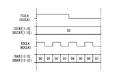
TSTAT及びTSCLKの送信波形の一例を図10に示す。図10において、"F"は、TSTATで送信されるデータフレームの先頭位置を示すとともにデータフレームの同期を取るためのフレーミング・パタンである。"S0乃至S15"は、FIFO情報がマッピングされるステータスワードである。ステータスワードとは、FIFOバッファに格納されたデータ量を示す情報(FIFO情報)であって、SPI−4 Phase2規格では、2ビットのデータとしてあらわされる。図10に示す例では、TSTATの1フレーム内に16個のステータスワード(S0乃至S15の)が含まれるため、16個のFIFOバッファに関するFIFO情報を転送可能である。また、"DIP2"は、誤り検出用のパリティ・ビットである。TSTATの1フレーム内に含まれるステータスワードの数(長さ)は、送信すべきFIFO情報の数、つまりFIFOバッファの数に応じて決定される。なお、SPI−4 Phase2規格では、TSTATの1フレーム内に含まれるステータスワード長をカレンダー長と呼ぶ。また、各FIFOバッファに関するFIFO情報は、1フレーム毎に周期的に転送される。つまり、複数のFIFOバッファには、各FIFOバッファの識別子に応じてTSTATのフレーム内の特定のタイムスロット(ステータスワード)が割り付けられ、1フレーム毎に周期的に転送される。
An example of transmission waveforms of TSTAT and TSCLK is shown in FIG. In FIG. 10, “F” is a framing pattern for indicating the head position of a data frame transmitted by TSTAT and for synchronizing the data frame. “S0 to S15” are status words to which the FIFO information is mapped. The status word is information (FIFO information) indicating the amount of data stored in the FIFO buffer, and is represented as 2-bit data in the SPI-4
SPI−4インタフェースは、ペイロードデータがPHYデバイス8からリンクレイヤ・デバイス7に向かう受信方向についても上述した送信方向と同様のチャネルを有する。具体的に述べると、SPI−4インタフェースは、受信データ信号チャネル(RDAT)、受信コントロール信号チャネル(RCTL)、及び受信データクロックチャネル(RDCLK)を含む。さらに、SPI−4インタフェースは、受信ステータス信号チャネル(RSTAT)及び受信ステータスクロックチャネル(RSCLK)を含む。これらのチャネルの用途及び送信波形は、送信方向の対応するチャネルと同様であるため説明を省略する。
The SPI-4 interface has the same channel as the transmission direction described above in the reception direction in which payload data is directed from the
なお、上述したデータクロック(TDCLK及びRDCLK)の周波数は、ステータスクロック(TSCLK及びRSCLK)の周波数の4倍に規定されている。このため、ステータスクロック(TSCLK及びRSCLK)の1周期を単位時間とすると、図11に示すように、ステータス信号チャネル(TSTAT及びRSTAT)で1つのステータスワードが転送される間に、データ信号チャネル(TDAT及びRDAT)で8つのデータワードを転送可能である。ステータ信号チャネル(TSTAT及びRSTAT)は2ビット幅であり、データ信号チャネル(TDAT及びRDAT)は16ビット幅であるから、つまり、データ信号チャネルはステータス信号チャネルの32倍のデータ転送レートを有する。 Note that the frequency of the data clock (TDCLK and RDCLK) is defined to be four times the frequency of the status clock (TSCLK and RSCLK). Therefore, if one period of the status clocks (TSCLK and RSCLK) is defined as a unit time, as shown in FIG. 11, the data signal channel (TSTAT and RSTAT) is transferred while one status word is being transferred in the status signal channel (TSTAT and RSTAT). Eight data words can be transferred with TDAT and RDAT). Since the status signal channels (TSTAT and RSTAT) are 2 bits wide and the data signal channels (TDAT and RDAT) are 16 bits wide, the data signal channel has a data transfer rate 32 times that of the status signal channel.
次に、図8に示すリンクレイヤ・デバイス7に含まれる構成要素について説明する。受信部72は、RDATにより受信したデータを格納するための4つのFIFOバッファ122乃至125を有している。なお、受信部72が備えるべきFIFOバッファ数がSPI−4 Phase2規格において規定されているわけではなく、図8に示すFIFOバッファ数が一例であることはもちろんである。RDATにより受信されたデータは、受信データ分配部121により4つのFIFOバッファ122乃至125に振り分けられる。FIFO情報出力部126は、FIFOバッファ122乃至125による受信データの格納状況に応じたFIFO情報を生成し、生成されたFIFO情報をRSTATに出力する。
Next, components included in the
送信部71が有するデータ出力部711は、TDATにペイロードデータ及びコントロールワードを出力する。また、FIFO情報受信部112は、対向するPHYデバイス8よりTSTATを介して取得したFIFO情報に基づいて、データ出力部711に停止信号を出力する。なお、FIFO情報を用いたフロー制御の詳細については後述する。停止信号を受信したデータ出力部711は、停止信号が解除されるまでの間、TDATに接続されたデータ送信ポートに対するデータ出力を停止する。
A
続いて以下では、従来のSPI−4インタフェースにおけるFIFO情報を用いたフロー制御について説明する。SPI−4 Phase2規格では、データ信号チャネル(TDAT及びRDAT)を介して受信されたデータを格納するためのFIFOバッファの使用状態を、STARVING、HUNGRY、及びSATISFIEDの3つの状態のいずれかに分類している。また、これら3つの使用状態に対して、2ビットのFIFO情報によりユニークなビットパタンが割り当てられている。FIFOバッファの使用状態とFIFO情報の関係を図12に示す。STARVING状態は、バッファ・アンダーフローが発生しそうな状況を示しており、FIFOの格納データ量が第1の閾値AEを下回る場合にSTARVING状態と判定される。STARVING状態を示すFIFO情報のビットパタンは、"00"である。SATISFIED状態は、FIFOが殆ど一杯であることを示しており、FIFOの格納データ量が第2の閾値AFを上回る場合にSATISFIED状態と判定される。なお、第2の閾値AFが第1の閾値AEより大きい値であることはもちろんである。SATISFIED状態を示すFIFO情報のビットパタンは、"10"である。最後に、HUNGRY状態は、STARVING状態とSATISFIED状態の間の状態を示している。HUNGRY状態を示すFIFO情報のビットパタンは、"01"である。
Next, flow control using FIFO information in the conventional SPI-4 interface will be described below. In the SPI-4
リンクレイヤ・デバイス7及びPHYデバイス8は、ステータス信号チャネル(TSTAT及びRSTAT)により対向するデバイスから受信したFIFO情報に応じて、自らのデータ送信レートを調整するフロー制御を実行する。具体的には、受信したFIFO情報がSTARVING状態を示す場合は、データ信号チャネル(TDAT及びRDAT)に最も高いデータ送信レートを適用する。受信したFIFO情報がHUNGRY状態を示す場合は、データ信号チャネル(TDAT及びRDAT)のデータ送信レートをSTARVING状態の場合に比べて低下させる。また、受信したFIFO情報がSATISFIED状態を示す場合は、次にFIFO情報が変化するまでの間、少なくともSATISFIED状態であるFIFOバッファに対するデータ信号チャネル(TDAT及びRDAT)によるデータ送信を停止させる。
上述した従来のSPI−4インタフェースにおけるFIFO情報を用いたフロー制御には、以下に述べる2つの問題点がある。 The flow control using the FIFO information in the conventional SPI-4 interface described above has the following two problems.
まず第1に、FIFO情報に優先度をつけることができないという問題点がある。従来のSPI−4インタフェースでは、複数のFIFOバッファそれぞれの状態を示すFIFO情報は、全て一律に、ステータス信号チャネル(TSTAT及びRSTAT)によって定期的に対向側に転送される。このため、従来のSPI−4インタフェースは、突発的に発生する緊急性の高いFIFO情報の転送要求に対応することが困難である。 First, there is a problem that priorities cannot be given to FIFO information. In the conventional SPI-4 interface, all the FIFO information indicating the state of each of the plurality of FIFO buffers is regularly transferred to the opposite side by the status signal channels (TSTAT and RSTAT). For this reason, it is difficult for the conventional SPI-4 interface to cope with a transfer request of FIFO information that occurs suddenly and is highly urgent.
第2に、カレンダー長が長くなるに応じて、FIFOバッファの状態変化の発生から対向側のデバイスにてフロー制御が実行されるまでに要する時間の最大値(以下、ワースト応答時間と呼ぶ)が長くなるという問題点がある。ワースト応答時間が長いほど第2の閾値AFを低く設定する必要があるため、上述した第2の問題点はFIFOバッファの使用効率の低下を招く。 Second, as the calendar length becomes longer, the maximum time (hereinafter referred to as the worst response time) required from the occurrence of the FIFO buffer state change until the flow control is executed in the opposite device is obtained. There is a problem that it becomes long. Since the second threshold value AF needs to be set lower as the worst response time becomes longer, the second problem described above causes a decrease in the use efficiency of the FIFO buffer.
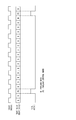
図13及び14を参照して、第2の問題点について詳しく説明する。図13は、RSTATにより転送されるデータフレームの一例を示している。図13の例によれば、10個のステータスワード(S1〜S10)によって10個のFIFOバッファに関するFIFO情報が周期的に転送される。また、図13は、リンクレイヤ・デバイスが有する識別番号#5のFIFOバッファの状態がHUNGRY状態からSATISFIED状態に変化し、これに応じて、PHYデバイスによるRDATへのデータ送信が停止されるまでの応答時間を示している。この応答時間は、図13に示す遅延時間Lat_a、TS、及びLat_cの和により定まる。つまりこの応答時間は、FIFO情報S5(識別番号#5のFIFOバッファの状態を示す情報)が更新されない最長時間(ワーストケース)を示すものである。
The second problem will be described in detail with reference to FIGS. FIG. 13 shows an example of a data frame transferred by RSTAT. According to the example of FIG. 13, FIFO information related to 10 FIFO buffers is periodically transferred by 10 status words (S1 to S10). In addition, FIG. 13 shows that the state of the FIFO buffer with the
図13において、遅延時間Lat_aは、FIFOバッファ#5の状態が変化してからFIFO情報が生成・更新されるまでの時間である。TSは、フレーミング・パタンが繰り返される期間の1周期分の時間である(図10においては、18×TSTATクロックの1周期の時間)。また、遅延時間Lat_cは、更新されたFIFO情報がリンクレイヤ・デバイスにより送信されてから対向するPHYデバイスがフロー制御を実行するまでの時間である。なお、図13及び14に示すLat_bは、カレンダー長×ステータス・クロック1周期の時間(TSTATクロックの1周期の時間)である。
In FIG. 13, the delay time Lat_a is the time from when the state of the
上述した3つの遅延時間のうち、Lat_a及びLat_cは一定である。一方、遅延時間Lat_bは、カレンダー長に依存して変動する時間である。このため、従来のSPI−4インタフェースにおけるワースト応答時間LWPは、図13に示すように、Lat_a、Lat_c及びTSの和で表される。TSTATのデータフレーム周期TSはカレンダー長が大きくなるにしたがって大きくなるため、ワースト応答時間LWPもカレンダー長が大きくなるにしたがって大きくなる。 Of the three delay times described above, Lat_a and Lat_c are constant. On the other hand, the delay time Lat_b is a time that varies depending on the calendar length. Therefore, the worst response time LWP in the conventional SPI-4 interface, as shown in FIG. 13, Lat_a, represented by the sum of Lat_c and T S. Since the data frame period T S of TSTAT increases as the calendar length increases, also increases in accordance with the calendar length increases LWP worst response time.
本発明にかかる通信システムは、SPI−4 Phase2規格の通信システムであって、自局デバイスと、対向デバイスと、前記自局デバイスから前記対向デバイスにペイロードデータを転送する第1のデータ信号チャネルと、前記対向デバイスから前記自局デバイスにペイロードデータを転送する第2のデータ信号チャネルと、前記自局デバイスから前記対向デバイスにデータ転送可能な第1のステータス信号チャネルとを有する通信システムである。さらに、前記自局デバイスは、前記第2のデータ信号チャネルにより受信されたペイロードデータを格納するデータバッファと、前記データバッファの使用状態を示すバッファ状態情報を周期的に前記第1のステータス信号チャネルに出力するバッファ状態情報出力部と、前記バッファ状態情報の優先度に応じて、前記バッファ状態情報を前記ペイロードデータの間に選択的に挿入し、前記第1のデータ信号チャネルに出力するバッファ状態情報挿入部とを有する。また、前記対向デバイスは、前記第1のステータス信号チャネル及び前記第1のデータ信号チャネルを介して受信される前記バッファ状態情報に基づいて、前記第2のデータ信号チャネルへのペイロードデータの出力を制御するフロー制御手段を有する。
The communication system according to the present invention is an SPI-4
本発明の通信システムをSPI−4インタフェースと対応させると、例えば、第1のデータ信号チャネルがTDATに相当し、第2のデータ信号チャネルがRDATに相当し、第1のステータス信号チャネルがRSTATに相当し、バッファ状態情報がFIFO情報に相当する。 When the communication system of the present invention is associated with the SPI-4 interface, for example, the first data signal channel corresponds to TDAT, the second data signal channel corresponds to RDAT, and the first status signal channel corresponds to RSTAT. The buffer status information corresponds to the FIFO information.
上述のように本発明にかかる通信システムは、バッファ状態情報(FIFO情報)の優先度に応じて、バッファ状態情報(FIFO情報)をペイロードデータの間に選択的に挿入し、第1のデータ信号チャネル(TDAT)に出力する。このため、優先的に緊急に送信すべきバッファ状態情報を、第1のステータス信号チャネル(RSTAT)による送信を待つことなく、第1のデータ信号チャネル(TDAT)を使用して送信することができる。つまり、従来のSPI−4インタフェースにおいて、全てのFIFO情報をステータス信号チャネルによって周期的に転送する構成とは異なり、FIFO情報に優先度をつけ、このような優先度の高いFIFO情報に従って速やかにフロー制御を行うことができる。 As described above, the communication system according to the present invention selectively inserts the buffer status information (FIFO information) between the payload data according to the priority of the buffer status information (FIFO information). Output to channel (TDAT). For this reason, the buffer status information that should be urgently transmitted preferentially can be transmitted using the first data signal channel (TDAT) without waiting for transmission by the first status signal channel (RSTAT). . In other words, in the conventional SPI-4 interface, unlike the configuration in which all the FIFO information is periodically transferred by the status signal channel, the FIFO information is prioritized and flows promptly according to the FIFO information having such a high priority. Control can be performed.
また、優先的に緊急に送信すべきバッファ状態情報を、第1のステータス信号チャネル(RSTAT)による送信を待つことなく、第1のデータ信号チャネル(TDAT)を使用して送信することによってデータバッファ(FIFOバッファ)の状態変化が発生してから対向側のデバイスにおいてフロー制御が実行されるまでのワースト応答時間は、カレンダー長に依存しないという利点がある。つまり、カレンダー長が長くなってもワースト応答時間は悪化しないため、データバッファ(FIFOバッファ)の使用効率を向上させることができる。 Further, the buffer state information to be transmitted urgently with priority is transmitted by using the first data signal channel (TDAT) without waiting for transmission by the first status signal channel (RSTAT). There is an advantage that the worst response time from the occurrence of the (FIFO buffer) state change until the flow control is executed in the opposite device does not depend on the calendar length. That is, since the worst response time does not deteriorate even when the calendar length is increased, the use efficiency of the data buffer (FIFO buffer) can be improved.
本発明により、SPI−4インタフェースのようにフロー制御を行う通信システムにおいて、FIFO情報の送信を優先度に基づいて行うことができ、ワースト応答時間のカレンダー長への依存性をなくすことができる。 According to the present invention, in a communication system that performs flow control like the SPI-4 interface, it is possible to transmit FIFO information based on priority, and to eliminate the dependency of the worst response time on the calendar length.
以下では、本発明を適用した具体的な実施の形態について、図面を参照しながら詳細に説明する。各図面において、同一要素には同一の符号が付されており、説明の明確化のため、必要に応じて重複説明は省略される。なお、以下に示す実施の形態では、ペイロードデータを格納するデータバッファをFIFOバッファとした場合について説明する。 Hereinafter, specific embodiments to which the present invention is applied will be described in detail with reference to the drawings. In the drawings, the same elements are denoted by the same reference numerals, and redundant description is omitted as necessary for the sake of clarity. In the following embodiment, a case where the data buffer for storing payload data is a FIFO buffer will be described.
発明の実施の形態1.
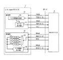
本実施の形態にかかる通信システムのブロック図を図1に示す。図1に示す通信システムは、本発明により改良されたSPI−4インタフェースにより接続されるリンクレイヤ・デバイス1及びPHYデバイス2を含んで構成される。
FIG. 1 shows a block diagram of a communication system according to the present embodiment. The communication system shown in FIG. 1 includes a
リンクレイヤ・デバイス1は、送信部11及び受信部12を有する。受信部12が有する受信データ分配部121、FIFOバッファ122乃至125、並びにFIFO情報(バッファ状態情報)出力部126はそれぞれ、上述した従来の受信部72が有する各構成要素と同一でよい。
The
送信部11が有するデータ出力部111は、TDATにペイロードデータ及びコントロールワードを出力する点と、FIFO情報(バッファ状態情報)受信部112より出力される停止信号に応じてデータ出力を停止する点においては、従来の送信部71が有するデータ出力部711と同様である。これらに加えてデータ出力部111は、FIFO情報挿入部113を有している。
The
FIFO情報(バッファ状態情報)挿入部113は、FIFOバッファ122乃至125のデータ格納状況を示すFIFO情報(バッファ状態情報)をペイロードデータの間に挿入してTDATに出力することができる。なお、FIFO情報をペイロードデータの間に挿入してTDATに出力するか否かを決定するためのトリガ要因は様々に設定可能であるが、本実施の形態では、FIFO情報をTDATに出力するか否かをFIFO情報の優先度に応じて決定することとする。例えば、FIFOバッファ121乃至125のうちのいずれかの使用状態がSATISFIED状態に変化した場合に、この状態変化を示すFIFO情報と、状態変化のあったFIFOバッファを一意に識別可能な識別情報(以下では、FIFOアドレスと呼ぶ)をTDATに出力すればよい。また、別の例として、FIFOバッファ121乃至125のうち、予め高い優先度を設定されたFIFOバッファの状態変化に応じて、この状態変化を示すFIFO情報及び対応するFIFOアドレスをTDATに出力してもよい。
The FIFO information (buffer status information)
一方、図1に示すPHYデバイス2は、図8に示したPHYデバイス8と比較して、リンクレイヤ・デバイス1からTDATを用いて転送されるFIFO情報に基づいてフロー制御を実行できるように改良されている点が異なる。
On the other hand, the
PHYデバイス2が有する送信部21は、データ出力部211及びFIFO情報受信部212を含んで構成される。データ出力部211は、RDATにペイロードデータ及びコントロールワードを出力する。また、FIFO情報受信部212は、対向するリンクレイヤ・デバイス1よりRSTATを介して取得したFIFO情報に基づいて、データ出力部211に停止信号S1を出力する。停止信号S1の出力は、例えば、FIFO情報により示されるFIFOバッファ121乃至125のいずれかの使用状態がSATISFIED状態である場合に行われる。停止信号S1を受信したデータ出力部211は、停止信号が解除されるまでの間、RDATに接続されたデータ送信ポートに対するデータ出力を停止する。より具体的に述べると、データ出力部211は、FIFOバッファ121乃至125のうち、少なくともSATISFIED状態であるFIFOバッファに対するペイロードデータの送信を停止する。
The
PHYデバイス2が有する受信部22は、FIFO情報抽出部221を含んで構成されている。FIFO情報抽出部221は、TDATを転送されるペイロードデータの間に挿入されたFIFO情報を抽出し、抽出されたFIFO情報に基づいて、データ出力部211に停止信号S2を出力する。なお、停止信号S2の出力は、例えば、FIFO情報により示されるFIFOバッファ121乃至125のいずれかの使用状態がSATISFIED状態である場合に行われる。停止信号S2を受信したデータ出力部211の動作は、上述した停止信号S1を受信した場合と同様である。
The
続いて以下では、FIFO情報挿入部113により行われるペイロードデータへのFIFO情報の挿入処理について、図2を用いて説明する。図2は、TDATに転送されるペイロードデータにFIFO情報を挿入する際の波形図を示している。図2の上段に示す3つの信号TDCLK、TCTL及びTDATは、TDATにFIFO情報が挿入されていない場合の信号波形図である。一方、図2の下段に示す2つの信号TCTL及びTDATは、TDATにFIFO情報32が挿入された場合の信号波形図である。FIFO情報32の挿入によって、ペイロードデータが前半部分31と後半部分33に分割される。また、FIFO情報が挿入されていることを対向するPHYデバイス2に伝達するために、FIFO情報の挿入に応じてTCTLがHighレベルに設定される。
Subsequently, the processing for inserting FIFO information into payload data performed by the FIFO
なお、図2において、"PC"は、SPI−4 Phase2規格で規定されたペイロード・コントロールワードを示している。また、"EOE"は、SPI−4 Phase2規格Appendix Eに規定された"End of Control Word Extension"を示している。図2に示した例では、PC及びEOEの組合せによってFIFO情報を転送している。
In FIG. 2, “PC” indicates a payload control word defined by the SPI-4
PC及びEOEの4バイトによって1つのFIFOバッファに関するFIFO情報を転送する場合のビット割り当ての一例を図3に示す。図3に示す例では、PCの第4ビットから第11ビットまでをFIFOアドレスの転送のために割り当て、EOEの第4ビットから第11ビットまでをFIFOバッファの使用状況を示すFIFO蓄積情報の転送のために割り当てている。これら以外のPC及びEOEの各ビットの内容は、SPI−4 Phase2規格により規定されている。
FIG. 3 shows an example of bit allocation when transferring FIFO information related to one FIFO buffer by 4 bytes of PC and EOE. In the example shown in FIG. 3, the 4th to 11th bits of the PC are allocated for the transfer of the FIFO address, and the 4th to 11th bits of the EOE are transferred for the FIFO accumulation information indicating the use status of the FIFO buffer. Assigned for. The contents of each bit of PC and EOE other than these are defined by the SPI-4
図3に示すビット割り当てによれば、EOEに含まれる8ビットをFIFOの使用状態を示すFIFO蓄積情報に割り当てている。このため、最大256通りの詳細なFIFOバッファの使用状態を対向するデバイスに伝達することができる。したがって、従来の3通りの状態の区別に基づくフロー制御に比べて、より詳細なフロー制御を行うことができる。また、図3に示す例では、FIFOアドレスを併せて転送しているため、データ停止の対象とすべきFIFOバッファを特定し、当該FIFOバッファに対するデータ送信のみを選択的に停止することができる。 According to the bit allocation shown in FIG. 3, 8 bits included in the EOE are allocated to FIFO accumulation information indicating the use state of the FIFO. Therefore, it is possible to transmit up to 256 detailed FIFO buffer usage states to the opposing device. Therefore, more detailed flow control can be performed as compared with the conventional flow control based on the distinction between three states. In the example shown in FIG. 3, since the FIFO address is transferred together, it is possible to specify the FIFO buffer that should be the target of data stop and selectively stop only the data transmission to the FIFO buffer.
なお、PC及びEOEの4バイトによってFIFO情報を転送する図2及び3に示した構成は一例に過ぎない。例えば、図4に示すように、PC及びEOEだけではなく、SPI−4 Phase2規格Appendix Eに規定された"EXT(Extension Control)"をFIFO情報の転送に使用してもよい。
The configuration shown in FIGS. 2 and 3 in which the FIFO information is transferred by 4 bytes of PC and EOE is only an example. For example, as shown in FIG. 4, not only PC and EOE, but also “EXT (Extension Control)” defined in SPI-4
また、図5に示すように、PC及びEOEそれぞれによって、1つのFIFOバッファに関するFIFO情報が転送されてもよい。このような構成によれば、図3に示す例に比べて、対向するデバイスに対するFIFO情報の伝達をより短時間で行うことができる。 Further, as shown in FIG. 5, FIFO information related to one FIFO buffer may be transferred by each of the PC and the EOE. According to such a configuration, the FIFO information can be transmitted to the opposite device in a shorter time than in the example shown in FIG.
上述したように、本実施の形態では、リンクレイヤ・デバイス1が、優先的に緊急に送信すべきFIFO情報を、ステータス信号チャネル(RSTAT)による送信を待つことなく、データ信号チャネル(TDAT)を使用して送信することとしている。また、PHYデバイス2は、データ信号チャネル(TDAT)より受信したFIFO情報に応じてフロー制御を実行する。つまり、従来のSPI−4インタフェースにおいて、全てのFIFO情報をステータス信号チャネルによって周期的に転送する構成とは異なり、FIFO情報に優先度をつけ、このような優先度の高いFIFO情報に従って速やかにフロー制御を行うことができる。
As described above, in the present embodiment, the
また、本実施の形態では、優先的に緊急に送信すべきFIFO情報を、ステータス信号チャネル(RSTAT)による送信を待つことなく、データ信号チャネル(TDAT)を使用して送信する。このため、FIFOバッファの状態変化が発生してから対向側のデバイスにおいてフロー制御が実行されるまでのワースト応答時間は、カレンダー長に依存しないという利点がある。つまり、本実施の形態におけるワースト応答時間LWNは、図6に示すようにカレンダー長に拠らず一定となる。このように、ワースト応答時間LWNを固定遅延成分のみによって推定することができれば、上述した第1の閾値AE及び第2の閾値AFを決定する等のシステム設計が容易となる。また、カレンダー長が長くなってもワースト応答時間は悪化しないため、FIFOバッファ121乃至125の使用効率を向上させることができる。 Further, in the present embodiment, FIFO information that should be urgently transmitted preferentially is transmitted using the data signal channel (TDAT) without waiting for transmission via the status signal channel (RSTAT). For this reason, there is an advantage that the worst response time from when the state change of the FIFO buffer occurs until the flow control is executed in the opposite device does not depend on the calendar length. That is, the worst response time LWN in the present embodiment is constant regardless of the calendar length as shown in FIG. As described above, if the worst response time LWN can be estimated only by the fixed delay component, the system design such as determining the first threshold value AE and the second threshold value AF described above becomes easy. In addition, since the worst response time does not deteriorate even when the calendar length is increased, the usage efficiency of the FIFO buffers 121 to 125 can be improved.
またさらに、ステータス信号チャネル(RSTAT)に比べてデータ送信レートが高いデータ信号チャネル(TDAT)を使用してFIFO情報を送信するため、対向側のデバイスによるフロー制御が実行されるまでの応答時間を短縮することができる。加えて、図3乃至5に示したように、ステータス信号チャネルを使用する場合に比べて、従来のFIFO情報より詳細な情報を短い時間で転送可能である。 Furthermore, since the FIFO information is transmitted using the data signal channel (TDAT) having a higher data transmission rate than the status signal channel (RSTAT), the response time until the flow control by the device on the opposite side is executed is reduced. It can be shortened. In addition, as shown in FIGS. 3 to 5, it is possible to transfer more detailed information than the conventional FIFO information in a shorter time compared to the case where the status signal channel is used.
なお、本実施の形態に関する上述した説明では、説明の簡略化のために、受信方向のフロー制御をデータ信号チャネル(TDAT)により転送されるFIFO情報を用いて行う構成について示した。しかしながら、送信方向のフロー制御をデータ信号チャネル(RDAT)により転送されるFIFO情報を用いて行うこともできる。 Note that, in the above description regarding the present embodiment, for the sake of simplicity, a configuration in which flow control in the reception direction is performed using FIFO information transferred by a data signal channel (TDAT) is shown. However, flow control in the transmission direction can also be performed using FIFO information transferred by the data signal channel (RDAT).
発明の実施の形態2.
発明の実施の形態1では、突発的に発生する緊急性の高いFIFO情報の転送を、データ信号チャネル(TDAT及びRDAT)を用いて行うことした。このような発明の実施の形態1の動作に代えて、又は、発明の実施の形態1の動作に加えて、データ信号チャネル(TDAT及びRDAT)を用いて周期的にFIFO情報を転送してもよい。
In the first embodiment of the invention, the transfer of FIFO information that occurs suddenly and has high urgency is performed using the data signal channels (TDAT and RDAT). Instead of the operation of the first embodiment of the invention or in addition to the operation of the first embodiment of the invention, the FIFO information may be periodically transferred using the data signal channels (TDAT and RDAT). Good.
図7は、データ信号チャネル(TDAT及びRDAT)を用いて周期的にFIFO情報を転送する例を示す波形図である。予めFIFO情報の送信順序を決定しておけば、周期的にFIFO情報を送信する際にFIFOアドレスを併せて転送することは不要となる。すなわち、図7に示すように、FIFO情報の転送に使用可能なコントロールワードの第4ビットから第11ビットを全てFIFO蓄積情報の転送に使用することができる。図7の例では、各FIFOバッファの使用状態を示すためのFIFO蓄積情報のビット数は、従来と同様に2ビットとしている。上述したように、SPI−4 Phase2において、データクロック(RDCLK及びTDCLK)はステータスクロック(RSCLK及びTSCLK)の4倍の周波数とされている。さらに、データクロック(RDCLK及びTDCLK)の立ち上がり及び立ち下がりの両方のエッジを使用してTDATにデータ信号が送信される。このため、本実施の形態におけるFIFO情報の転送レートは、従来に比べて32倍に高速化される。
FIG. 7 is a waveform diagram showing an example in which FIFO information is periodically transferred using data signal channels (TDAT and RDAT). If the transmission order of the FIFO information is determined in advance, it is not necessary to transfer the FIFO address together when periodically transmitting the FIFO information. That is, as shown in FIG. 7, all the 4th to 11th bits of the control word that can be used for transferring the FIFO information can be used for transferring the FIFO accumulated information. In the example of FIG. 7, the number of bits of FIFO accumulation information for indicating the use state of each FIFO buffer is 2 bits as in the conventional case. As described above, in SPI-4
その他の実施の形態.
上述した発明の実施の形態1及び2において、FIFO情報の転送に、データ信号チャネル(TDAT及びRDAT)のみを使用するか、ステータス信号チャネル(TSTAT及びRSTAT)のみを使用するか、又は、これら両方のチャネルを併用するかを選択可能としてもよい。
Other embodiments.
In the first and second embodiments of the present invention described above, only the data signal channels (TDAT and RDAT), only the status signal channels (TSTAT and RSTAT), or both of them are used for transferring the FIFO information. It may be possible to select whether to use both channels.
さらに、本発明は上述した実施の形態のみに限定されるものではなく、既に述べた本発明の要旨を逸脱しない範囲において種々の変更が可能であることは勿論である。 Furthermore, the present invention is not limited to the above-described embodiments, and various modifications can be made without departing from the gist of the present invention described above.
1 リンクレイヤ・デバイス
11 送信部
12 受信部
111 データ出力部
112 FIFO情報受信部
113 FIFO情報挿入部
121 受信データ分配部
122乃至125 FIFOバッファ
126 FIFO情報出力部
2 PHYデバイス
21 送信部
22 受信部
211 データ出力部
212 FIFO情報受信部
221 FIFO情報抽出部
DESCRIPTION OF
Claims (23)
自局デバイスと、
対向デバイスと、
前記自局デバイスから前記対向デバイスにペイロードデータを転送する第1のデータ信号チャネルと、
前記対向デバイスから前記自局デバイスにペイロードデータを転送する第2のデータ信号チャネルと、
前記自局デバイスから前記対向デバイスにデータ転送可能な第1のステータス信号チャネルと、
を備える通信システムであって、
前記自局デバイスは、
前記第2のデータ信号チャネルにより受信されたペイロードデータを格納するデータバッファと、
前記データバッファの使用状態を示すバッファ状態情報を周期的に前記第1のステータス信号チャネルに出力するバッファ状態情報出力部と、
前記バッファ状態情報の優先度に応じて、前記バッファ状態情報を前記ペイロードデータの間に選択的に挿入し、前記第1のデータ信号チャネルに出力するバッファ状態情報挿入部とを有し、
前記対向デバイスは、
前記第1のステータス信号チャネル及び前記第1のデータ信号チャネルを介して受信される前記バッファ状態情報に基づいて、前記第2のデータ信号チャネルへのペイロードデータの出力を制御するフロー制御手段を有する通信システム。 SPI-4 Phase 2 standard communication system,
Your own device,
An opposing device;
A first data signal channel for transferring payload data from the local station device to the opposite device;
A second data signal channel for transferring payload data from the opposite device to the local station device;
A first status signal channel capable of transferring data from the local station device to the opposite device;
A communication system comprising:
The local station device is
A data buffer for storing payload data received by the second data signal channel;
A buffer status information output unit that periodically outputs buffer status information indicating a use status of the data buffer to the first status signal channel;
A buffer status information insertion unit that selectively inserts the buffer status information between the payload data according to the priority of the buffer status information and outputs the data to the first data signal channel;
The opposing device is
Flow control means for controlling output of payload data to the second data signal channel based on the buffer status information received via the first status signal channel and the first data signal channel; Communications system.
前記第1のステータス信号チャネルより受信したデータから前記バッファ状態情報を受信するバッファ状態情報受信部と、
前記第1のデータ信号チャネルより受信したデータから前記バッファ状態情報を抽出するバッファ状態情報抽出部と、
前記バッファ状態情報受信部及び前記バッファ状態情報抽出部により取得された前記バッファ状態情報に基づいて、前記第2のデータ信号チャネルへのペイロードデータの出力を停止可能なデータ出力部とを有する請求項1に記載の通信システム。 The flow control means includes
A buffer status information receiving unit for receiving the buffer status information from data received from the first status signal channel;
A buffer status information extraction unit for extracting the buffer status information from data received from the first data signal channel;
A data output unit capable of stopping output of payload data to the second data signal channel based on the buffer status information acquired by the buffer status information receiving unit and the buffer status information extracting unit. The communication system according to 1.
前記バッファ状態情報挿入部は、前記バッファアドレスと前記バッファ蓄積情報とをExtension Controlに割り当てて前記バッファ状態情報を転送する請求項1記載の通信システム。 The buffer status information includes at least a buffer address and buffer accumulation information indicating a usage status of the data buffer,
The communication system according to claim 1, wherein the buffer status information insertion unit assigns the buffer address and the buffer accumulation information to Extension Control and transfers the buffer status information.
前記対向装置にペイロードデータを送信するためのデータ送信ポートと、
前記対向装置からペイロードデータを受信するためのデータ受信ポートと、
前記データ受信ポートにより受信されたペイロードデータを格納するデータバッファと、
前記データバッファの使用状態を示すバッファ状態情報を周期的に前記対向装置に送信するために設けられ、前記データ送信ポートよりデータ転送レートが低いステータス送信ポートと、
前記バッファ状態情報を前記第1のステータス信号ポートに出力するバッファ状態情報出力部と、
前記バッファ状態情報の優先度に応じて、前記バッファ状態情報を前記ペイロードデータの間に選択的に挿入して前記データ送信ポートに出力するバッファ状態情報挿入部と、
を備える通信装置。
An SPI-4 Phase 2 standard communication device that transmits and receives data to and from the opposite device,
A data transmission port for transmitting payload data to the opposite device;
A data receiving port for receiving payload data from the opposite device;
A data buffer for storing payload data received by the data receiving port;
A status transmission port that is provided for periodically transmitting buffer status information indicating the usage status of the data buffer to the opposite device, and has a data transfer rate lower than the data transmission port;
A buffer status information output unit for outputting the buffer status information to the first status signal port;
A buffer status information insertion unit that selectively inserts the buffer status information between the payload data and outputs it to the data transmission port according to the priority of the buffer status information;
A communication device comprising:
前記自局デバイスが、前記第2のデータ信号チャネルにより受信されたペイロードデータを格納するデータバッファの使用状態を示すバッファ状態情報を前記第1のステータス信号チャネルに周期的に送信し、
前記自局デバイスが、前記バッファ状態情報の優先度に応じて、前記バッファ状態情報を前記ペイロードデータの間に選択的に挿入して前記第1のデータ信号チャネルに出力し、
前記対向デバイスが、前記第1のステータス信号チャネル及び前記第1のデータ信号チャネルを介して受信される前記状態情報に基づいて、前記第2のデータ信号チャネルへのペイロードデータの出力を制御する、フロー制御方法。 A first data signal channel for transferring payload data from the own station device to the opposite device, and a second data signal for transferring payload data from the opposite device to the own device. A flow control method in an SPI-4 Phase 2 standard communication system comprising a channel and a first status signal channel capable of transferring data from the local station device to the opposite device,
The local station device periodically transmits to the first status signal channel buffer status information indicating a usage status of a data buffer that stores payload data received by the second data signal channel.
The local station device selectively inserts the buffer status information between the payload data according to the priority of the buffer status information, and outputs it to the first data signal channel;
The opposing device controls the output of payload data to the second data signal channel based on the status information received via the first status signal channel and the first data signal channel; Flow control method.
Priority Applications (2)
| Application Number | Priority Date | Filing Date | Title |
|---|---|---|---|
| JP2007017646A JP4773377B2 (en) | 2007-01-29 | 2007-01-29 | COMMUNICATION SYSTEM, COMMUNICATION DEVICE, AND FLOW CONTROL METHOD |
| US12/010,253 US7765335B2 (en) | 2007-01-29 | 2008-01-23 | Communication system, communication device and flow control based on status information of data buffer usage |
Applications Claiming Priority (1)
| Application Number | Priority Date | Filing Date | Title |
|---|---|---|---|
| JP2007017646A JP4773377B2 (en) | 2007-01-29 | 2007-01-29 | COMMUNICATION SYSTEM, COMMUNICATION DEVICE, AND FLOW CONTROL METHOD |
Publications (2)
| Publication Number | Publication Date |
|---|---|
| JP2008187336A JP2008187336A (en) | 2008-08-14 |
| JP4773377B2 true JP4773377B2 (en) | 2011-09-14 |
Family
ID=39669220
Family Applications (1)
| Application Number | Title | Priority Date | Filing Date |
|---|---|---|---|
| JP2007017646A Expired - Fee Related JP4773377B2 (en) | 2007-01-29 | 2007-01-29 | COMMUNICATION SYSTEM, COMMUNICATION DEVICE, AND FLOW CONTROL METHOD |
Country Status (2)
| Country | Link |
|---|---|
| US (1) | US7765335B2 (en) |
| JP (1) | JP4773377B2 (en) |
Cited By (4)
| Publication number | Priority date | Publication date | Assignee | Title |
|---|---|---|---|---|
| US11026627B2 (en) | 2013-03-15 | 2021-06-08 | Cadwell Laboratories, Inc. | Surgical instruments for determining a location of a nerve during a procedure |
| US11177610B2 (en) | 2017-01-23 | 2021-11-16 | Cadwell Laboratories, ino. | Neuromonitoring connection system |
| US11253182B2 (en) | 2018-05-04 | 2022-02-22 | Cadwell Laboratories, Inc. | Apparatus and method for polyphasic multi-output constant-current and constant-voltage neurophysiological stimulation |
| US11443649B2 (en) | 2018-06-29 | 2022-09-13 | Cadwell Laboratories, Inc. | Neurophysiological monitoring training simulator |
Families Citing this family (8)
| Publication number | Priority date | Publication date | Assignee | Title |
|---|---|---|---|---|
| KR20090065230A (en) * | 2007-12-17 | 2009-06-22 | 한국전자통신연구원 | Wireless sensor network having hierarchical structure and method for routing for the same |
| CN102318345B (en) * | 2009-02-27 | 2014-07-30 | 富士通株式会社 | Moving image encoding apparatus and moving image encoding method |
| US9918669B2 (en) * | 2014-08-08 | 2018-03-20 | Medtronic Xomed, Inc. | Wireless nerve integrity monitoring systems and devices |
| US10039915B2 (en) | 2015-04-03 | 2018-08-07 | Medtronic Xomed, Inc. | System and method for omni-directional bipolar stimulation of nerve tissue of a patient via a surgical tool |
| US10445466B2 (en) | 2015-11-18 | 2019-10-15 | Warsaw Orthopedic, Inc. | Systems and methods for post-operative outcome monitoring |
| US10339273B2 (en) | 2015-11-18 | 2019-07-02 | Warsaw Orthopedic, Inc. | Systems and methods for pre-operative procedure determination and outcome predicting |
| US10849517B2 (en) | 2016-09-19 | 2020-12-01 | Medtronic Xomed, Inc. | Remote control module for instruments |
| TWI690806B (en) * | 2017-05-22 | 2020-04-11 | 義隆電子股份有限公司 | Data transmitting device and data receiving device for a serial peripheral interface |
Family Cites Families (10)
| Publication number | Priority date | Publication date | Assignee | Title |
|---|---|---|---|---|
| JPS62296640A (en) * | 1986-06-17 | 1987-12-23 | Fujitsu Ltd | Inter-equipment communication control system |
| JPH07143122A (en) * | 1993-06-18 | 1995-06-02 | Hitachi Ltd | Traffic control system |
| US6522271B2 (en) * | 2001-03-16 | 2003-02-18 | International Business Machines Corporation | Method and apparatus for transmission on a 2-bit channel using 3b/4b code |
| JP2003218955A (en) * | 2002-01-18 | 2003-07-31 | Seiko Epson Corp | Data transmission apparatus, terminal employing the same, and data transmission control method |
| US7039010B2 (en) * | 2002-03-06 | 2006-05-02 | Broadcom Corporation | Optimized data path structure for multi-channel management information base (MIB) event generation |
| US6642865B2 (en) * | 2002-03-12 | 2003-11-04 | International Business Machines Corporation | Scalable interface and method of transmitting data thereon |
| US7111102B2 (en) * | 2003-10-06 | 2006-09-19 | Cisco Technology, Inc. | Port adapter for high-bandwidth bus |
| US7421522B1 (en) * | 2004-12-01 | 2008-09-02 | Altera Corporation | Techniques for transmitting and receiving SPI4.2 status signals using a hard intellectual property block |
| JP2006302343A (en) * | 2005-04-15 | 2006-11-02 | Hitachi Global Storage Technologies Netherlands Bv | Information recording and reproducing device |
| JP2006324864A (en) * | 2005-05-18 | 2006-11-30 | Fujitsu Ltd | Network switch and back pressure control method |
-
2007
- 2007-01-29 JP JP2007017646A patent/JP4773377B2/en not_active Expired - Fee Related
-
2008
- 2008-01-23 US US12/010,253 patent/US7765335B2/en not_active Expired - Fee Related
Cited By (5)
| Publication number | Priority date | Publication date | Assignee | Title |
|---|---|---|---|---|
| US11026627B2 (en) | 2013-03-15 | 2021-06-08 | Cadwell Laboratories, Inc. | Surgical instruments for determining a location of a nerve during a procedure |
| US11177610B2 (en) | 2017-01-23 | 2021-11-16 | Cadwell Laboratories, ino. | Neuromonitoring connection system |
| US11949188B2 (en) | 2017-01-23 | 2024-04-02 | Cadwell Laboratories, Inc. | Methods for concurrently forming multiple electrical connections in a neuro-monitoring system |
| US11253182B2 (en) | 2018-05-04 | 2022-02-22 | Cadwell Laboratories, Inc. | Apparatus and method for polyphasic multi-output constant-current and constant-voltage neurophysiological stimulation |
| US11443649B2 (en) | 2018-06-29 | 2022-09-13 | Cadwell Laboratories, Inc. | Neurophysiological monitoring training simulator |
Also Published As
| Publication number | Publication date |
|---|---|
| JP2008187336A (en) | 2008-08-14 |
| US20080183915A1 (en) | 2008-07-31 |
| US7765335B2 (en) | 2010-07-27 |
Similar Documents
| Publication | Publication Date | Title |
|---|---|---|
| JP4773377B2 (en) | COMMUNICATION SYSTEM, COMMUNICATION DEVICE, AND FLOW CONTROL METHOD | |
| CN102132535B (en) | Method for transferring data packets in communication network and switching device | |
| US7502319B2 (en) | Ethernet packet transmission apparatus and method | |
| JP4931912B2 (en) | Signal transmission method, transmission / reception apparatus, and communication system | |
| US6757348B1 (en) | High-speed coordinated multi-channel elastic buffer | |
| EP1304850B1 (en) | Ethernet device and method for extending ethernet fifo buffer | |
| CN103975569A (en) | Method and apparatus for arbitration of time-sensitive data transmissions | |
| US8295293B1 (en) | Predictive flow control for a packet switch | |
| US7701979B2 (en) | Residential ethernet node apparatus for maintaining starting point of superframe and method for processing same | |
| KR100478112B1 (en) | Packet control system and communication method | |
| US20040257856A1 (en) | Dual-port functionality for a single-port cell memory device | |
| JP4955687B2 (en) | Interface rate adaptation of asynchronous line to physical layer with synchronous line in connection layer | |
| US6580711B1 (en) | Serial interface circuit and signal processing method of the same | |
| US8976651B2 (en) | Load balance control unit, load balance control method and storage medium | |
| EP1894370B1 (en) | Electronic device, method for frame synchronization, and mobile device | |
| KR101035766B1 (en) | Synchronous Data Constructing Method In Residential Ethernet System | |
| US6381240B1 (en) | Signal processing circuit and method of signal processing | |
| JP5178805B2 (en) | Communication control system | |
| JP2009206696A (en) | Transmission system | |
| CN103078812B (en) | Data forwarding method and equipment | |
| EP2017991A2 (en) | Adjusting the degree of filling of a jitter buffer | |
| JP4228850B2 (en) | Packet relay device | |
| CN101199156A (en) | Methods and receives of data transmission using clock domains | |
| KR20060107156A (en) | Asynchronous frame transmitting method for strict guarantee of super frame's start in residential ethernet | |
| CN109120628A (en) | Print system kilomega network communication means, terminal and system |
Legal Events
| Date | Code | Title | Description |
|---|---|---|---|
| A621 | Written request for application examination |
Free format text: JAPANESE INTERMEDIATE CODE: A621 Effective date: 20090910 |
|
| A977 | Report on retrieval |
Free format text: JAPANESE INTERMEDIATE CODE: A971007 Effective date: 20110221 |
|
| A131 | Notification of reasons for refusal |
Free format text: JAPANESE INTERMEDIATE CODE: A131 Effective date: 20110426 |
|
| A521 | Request for written amendment filed |
Free format text: JAPANESE INTERMEDIATE CODE: A523 Effective date: 20110603 |
|
| TRDD | Decision of grant or rejection written | ||
| A01 | Written decision to grant a patent or to grant a registration (utility model) |
Free format text: JAPANESE INTERMEDIATE CODE: A01 Effective date: 20110621 |
|
| A01 | Written decision to grant a patent or to grant a registration (utility model) |
Free format text: JAPANESE INTERMEDIATE CODE: A01 |
|
| A61 | First payment of annual fees (during grant procedure) |
Free format text: JAPANESE INTERMEDIATE CODE: A61 Effective date: 20110623 |
|
| FPAY | Renewal fee payment (event date is renewal date of database) |
Free format text: PAYMENT UNTIL: 20140701 Year of fee payment: 3 |
|
| R150 | Certificate of patent or registration of utility model |
Free format text: JAPANESE INTERMEDIATE CODE: R150 |
|
| LAPS | Cancellation because of no payment of annual fees |