JP2019532704A - Remote control module for instruments - Google Patents
Remote control module for instruments Download PDFInfo
- Publication number
- JP2019532704A JP2019532704A JP2019515506A JP2019515506A JP2019532704A JP 2019532704 A JP2019532704 A JP 2019532704A JP 2019515506 A JP2019515506 A JP 2019515506A JP 2019515506 A JP2019515506 A JP 2019515506A JP 2019532704 A JP2019532704 A JP 2019532704A
- Authority
- JP
- Japan
- Prior art keywords
- stimulation
- sterile field
- controller
- monitoring system
- stimulus
- Prior art date
- Legal status (The legal status is an assumption and is not a legal conclusion. Google has not performed a legal analysis and makes no representation as to the accuracy of the status listed.)
- Pending
Links
Images


Classifications
-
- A—HUMAN NECESSITIES
- A61—MEDICAL OR VETERINARY SCIENCE; HYGIENE
- A61B—DIAGNOSIS; SURGERY; IDENTIFICATION
- A61B5/00—Measuring for diagnostic purposes; Identification of persons
- A61B5/24—Detecting, measuring or recording bioelectric or biomagnetic signals of the body or parts thereof
-
- A—HUMAN NECESSITIES
- A61—MEDICAL OR VETERINARY SCIENCE; HYGIENE
- A61B—DIAGNOSIS; SURGERY; IDENTIFICATION
- A61B5/00—Measuring for diagnostic purposes; Identification of persons
- A61B5/24—Detecting, measuring or recording bioelectric or biomagnetic signals of the body or parts thereof
- A61B5/316—Modalities, i.e. specific diagnostic methods
- A61B5/389—Electromyography [EMG]
- A61B5/394—Electromyography [EMG] specially adapted for electroglottography or electropalatography
-
- A—HUMAN NECESSITIES
- A61—MEDICAL OR VETERINARY SCIENCE; HYGIENE
- A61B—DIAGNOSIS; SURGERY; IDENTIFICATION
- A61B5/00—Measuring for diagnostic purposes; Identification of persons
- A61B5/40—Detecting, measuring or recording for evaluating the nervous system
- A61B5/4029—Detecting, measuring or recording for evaluating the nervous system for evaluating the peripheral nervous systems
- A61B5/4035—Evaluating the autonomic nervous system
-
- A—HUMAN NECESSITIES
- A61—MEDICAL OR VETERINARY SCIENCE; HYGIENE
- A61B—DIAGNOSIS; SURGERY; IDENTIFICATION
- A61B5/00—Measuring for diagnostic purposes; Identification of persons
- A61B5/40—Detecting, measuring or recording for evaluating the nervous system
- A61B5/4029—Detecting, measuring or recording for evaluating the nervous system for evaluating the peripheral nervous systems
- A61B5/4041—Evaluating nerves condition
-
- A—HUMAN NECESSITIES
- A61—MEDICAL OR VETERINARY SCIENCE; HYGIENE
- A61B—DIAGNOSIS; SURGERY; IDENTIFICATION
- A61B5/00—Measuring for diagnostic purposes; Identification of persons
- A61B5/68—Arrangements of detecting, measuring or recording means, e.g. sensors, in relation to patient
- A61B5/6846—Arrangements of detecting, measuring or recording means, e.g. sensors, in relation to patient specially adapted to be brought in contact with an internal body part, i.e. invasive
- A61B5/6847—Arrangements of detecting, measuring or recording means, e.g. sensors, in relation to patient specially adapted to be brought in contact with an internal body part, i.e. invasive mounted on an invasive device
-
- A—HUMAN NECESSITIES
- A61—MEDICAL OR VETERINARY SCIENCE; HYGIENE
- A61B—DIAGNOSIS; SURGERY; IDENTIFICATION
- A61B5/00—Measuring for diagnostic purposes; Identification of persons
- A61B5/74—Details of notification to user or communication with user or patient ; user input means
- A61B5/7475—User input or interface means, e.g. keyboard, pointing device, joystick
-
- A—HUMAN NECESSITIES
- A61—MEDICAL OR VETERINARY SCIENCE; HYGIENE
- A61N—ELECTROTHERAPY; MAGNETOTHERAPY; RADIATION THERAPY; ULTRASOUND THERAPY
- A61N1/00—Electrotherapy; Circuits therefor
-
- A—HUMAN NECESSITIES
- A61—MEDICAL OR VETERINARY SCIENCE; HYGIENE
- A61N—ELECTROTHERAPY; MAGNETOTHERAPY; RADIATION THERAPY; ULTRASOUND THERAPY
- A61N1/00—Electrotherapy; Circuits therefor
- A61N1/18—Applying electric currents by contact electrodes
- A61N1/32—Applying electric currents by contact electrodes alternating or intermittent currents
- A61N1/36—Applying electric currents by contact electrodes alternating or intermittent currents for stimulation
- A61N1/36014—External stimulators, e.g. with patch electrodes
- A61N1/36017—External stimulators, e.g. with patch electrodes with leads or electrodes penetrating the skin
-
- A—HUMAN NECESSITIES
- A61—MEDICAL OR VETERINARY SCIENCE; HYGIENE
- A61B—DIAGNOSIS; SURGERY; IDENTIFICATION
- A61B18/00—Surgical instruments, devices or methods for transferring non-mechanical forms of energy to or from the body
- A61B18/04—Surgical instruments, devices or methods for transferring non-mechanical forms of energy to or from the body by heating
- A61B18/12—Surgical instruments, devices or methods for transferring non-mechanical forms of energy to or from the body by heating by passing a current through the tissue to be heated, e.g. high-frequency current
- A61B18/14—Probes or electrodes therefor
- A61B18/1442—Probes having pivoting end effectors, e.g. forceps
-
- A—HUMAN NECESSITIES
- A61—MEDICAL OR VETERINARY SCIENCE; HYGIENE
- A61B—DIAGNOSIS; SURGERY; IDENTIFICATION
- A61B18/00—Surgical instruments, devices or methods for transferring non-mechanical forms of energy to or from the body
- A61B2018/00636—Sensing and controlling the application of energy
- A61B2018/0066—Sensing and controlling the application of energy without feedback, i.e. open loop control
-
- A—HUMAN NECESSITIES
- A61—MEDICAL OR VETERINARY SCIENCE; HYGIENE
- A61B—DIAGNOSIS; SURGERY; IDENTIFICATION
- A61B18/00—Surgical instruments, devices or methods for transferring non-mechanical forms of energy to or from the body
- A61B2018/00636—Sensing and controlling the application of energy
- A61B2018/00773—Sensed parameters
- A61B2018/00839—Bioelectrical parameters, e.g. ECG, EEG
-
- A—HUMAN NECESSITIES
- A61—MEDICAL OR VETERINARY SCIENCE; HYGIENE
- A61B—DIAGNOSIS; SURGERY; IDENTIFICATION
- A61B18/00—Surgical instruments, devices or methods for transferring non-mechanical forms of energy to or from the body
- A61B2018/0091—Handpieces of the surgical instrument or device
-
- A—HUMAN NECESSITIES
- A61—MEDICAL OR VETERINARY SCIENCE; HYGIENE
- A61B—DIAGNOSIS; SURGERY; IDENTIFICATION
- A61B18/00—Surgical instruments, devices or methods for transferring non-mechanical forms of energy to or from the body
- A61B2018/0091—Handpieces of the surgical instrument or device
- A61B2018/00916—Handpieces of the surgical instrument or device with means for switching or controlling the main function of the instrument or device
- A61B2018/0094—Types of switches or controllers
-
- A—HUMAN NECESSITIES
- A61—MEDICAL OR VETERINARY SCIENCE; HYGIENE
- A61B—DIAGNOSIS; SURGERY; IDENTIFICATION
- A61B18/00—Surgical instruments, devices or methods for transferring non-mechanical forms of energy to or from the body
- A61B18/04—Surgical instruments, devices or methods for transferring non-mechanical forms of energy to or from the body by heating
- A61B18/12—Surgical instruments, devices or methods for transferring non-mechanical forms of energy to or from the body by heating by passing a current through the tissue to be heated, e.g. high-frequency current
- A61B18/14—Probes or electrodes therefor
- A61B18/1442—Probes having pivoting end effectors, e.g. forceps
- A61B2018/1452—Probes having pivoting end effectors, e.g. forceps including means for cutting
-
- A—HUMAN NECESSITIES
- A61—MEDICAL OR VETERINARY SCIENCE; HYGIENE
- A61B—DIAGNOSIS; SURGERY; IDENTIFICATION
- A61B18/00—Surgical instruments, devices or methods for transferring non-mechanical forms of energy to or from the body
- A61B18/04—Surgical instruments, devices or methods for transferring non-mechanical forms of energy to or from the body by heating
- A61B18/12—Surgical instruments, devices or methods for transferring non-mechanical forms of energy to or from the body by heating by passing a current through the tissue to be heated, e.g. high-frequency current
- A61B18/14—Probes or electrodes therefor
- A61B18/1442—Probes having pivoting end effectors, e.g. forceps
- A61B2018/146—Scissors
-
- A—HUMAN NECESSITIES
- A61—MEDICAL OR VETERINARY SCIENCE; HYGIENE
- A61B—DIAGNOSIS; SURGERY; IDENTIFICATION
- A61B2562/00—Details of sensors; Constructional details of sensor housings or probes; Accessories for sensors
- A61B2562/22—Arrangements of medical sensors with cables or leads; Connectors or couplings specifically adapted for medical sensors
- A61B2562/225—Connectors or couplings
-
- A—HUMAN NECESSITIES
- A61—MEDICAL OR VETERINARY SCIENCE; HYGIENE
- A61B—DIAGNOSIS; SURGERY; IDENTIFICATION
- A61B5/00—Measuring for diagnostic purposes; Identification of persons
- A61B5/48—Other medical applications
- A61B5/4887—Locating particular structures in or on the body
- A61B5/4893—Nerves
-
- A—HUMAN NECESSITIES
- A61—MEDICAL OR VETERINARY SCIENCE; HYGIENE
- A61B—DIAGNOSIS; SURGERY; IDENTIFICATION
- A61B5/00—Measuring for diagnostic purposes; Identification of persons
- A61B5/68—Arrangements of detecting, measuring or recording means, e.g. sensors, in relation to patient
- A61B5/6846—Arrangements of detecting, measuring or recording means, e.g. sensors, in relation to patient specially adapted to be brought in contact with an internal body part, i.e. invasive
- A61B5/6847—Arrangements of detecting, measuring or recording means, e.g. sensors, in relation to patient specially adapted to be brought in contact with an internal body part, i.e. invasive mounted on an invasive device
- A61B5/6852—Catheters
Abstract
モニタリングシステムが、プロセッサと、モニタリングからの結果を表示するためのディスプレイシステムとを有することができる。使用者が、プロセッサおよびディスプレイシステムならびに選択される入力デバイスから離れた無菌フィールド内にいてよい。コントローラが無菌フィールドからモニタリングシステムに物理的に接続され得、それにより使用者がモニタリングシステムを制御するのを可能にする。【選択図】図4The monitoring system can have a processor and a display system for displaying the results from the monitoring. The user may be in a sterile field remote from the processor and display system and the selected input device. A controller can be physically connected from the sterile field to the monitoring system, thereby allowing the user to control the monitoring system. [Selection] Figure 4
Description
[0001]本開示は神経モニタリングシステムに関し、より詳細には神経モニタリングシステムの遠隔制御に関する。 [0001] The present disclosure relates to nerve monitoring systems, and more particularly to remote control of nerve monitoring systems.
[0002]本セクションは本開示に関連する背景情報を提供するが、これは必ずしも従来技術ではない。
[0003]Medtronic,Inc.によって販売されているNIM−Response(登録商標)3.0および/またはNIM−Neuro(登録商標)3.0の神経モニタリングシステムなどの、神経モニタリングシステムは、筋電図(EMG:electromyography)反応を監視するのに使用され得る。具体的には、モニタリングシステムが、選択される神経のところに刺激を提供することができ、および刺激のロケーションから離れた筋肉のところで感知または検出される反応を提供することができる。EMG反応を監視することが、選択される手技中に1つまたは複数の神経がダメージを受けているか否かを判断するのに利用され得る。多様なシステムで、モニタリングシステムは、手技実施使用者(procedure user)および被験者から離れたところにいるモニタ使用者によって制御され得る。したがって、モニタ使用者が、手技実施使用者による選択される使用に従ってモニタリングシステムを動作させるために、手技実施使用者からの指示を必要とする可能性がある。
[0002] Although this section provides background information related to the present disclosure, this is not necessarily prior art.
[0003] Medtronic, Inc. Nerve monitoring systems, such as the NIM-Response® 3.0 and / or NIM-Neuro® 3.0 neuromonitoring systems sold by the US, are electromyographic (EMG) responses. Can be used to monitor. Specifically, the monitoring system can provide a stimulus at a selected nerve and can provide a response that is sensed or detected at a muscle away from the location of the stimulus. Monitoring the EMG response can be utilized to determine whether one or more nerves are damaged during the selected procedure. In various systems, the monitoring system can be controlled by procedure users and monitor users away from the subject. Accordingly, the monitor user may need instructions from the procedure performing user to operate the monitoring system in accordance with the usage selected by the procedure performing user.
[0004]本セクションは本開示の概要を提供するが、その全範囲およびその特徴のすべての包括的な開示というわけではない。
[0005]神経モニタリングシステムが神経の健全性(integrity)を監視するのに使用され得る。手技中、手技実施使用者が、手技実施使用者のところに設けられる遠隔制御システムを用いて、神経モニタリングシステムを動作させることができるおよび/または動作を変更することができる。遠隔制御システムが、手技実施使用者のロケーションにおいて手技実施使用者によって操作され得るハードウェアを有することができる。したがって、神経モニタリングシステムに対しての指示または制御が、モニタリングシステムから離れたロケーションにおいて実現され得る。
[0004] This section provides an overview of the disclosure, but is not an exhaustive disclosure of its full scope and features.
[0005] A nerve monitoring system may be used to monitor nerve integrity. During the procedure, the procedure performing user can operate and / or change the operation of the nerve monitoring system using a remote control system provided at the procedure performing user. The remote control system may have hardware that can be operated by the procedure performer at the location of the procedure performer. Thus, instructions or control for the neural monitoring system can be implemented at a location remote from the monitoring system.
[0006]モニタリングシステムは、プロセッサと、神経モニタリングからの結果を表示するための表示システムとを有することができる。しかし、モニタリングシステムは、無菌フィールド内に配置されるようにまたは被験者の近くに配置されるように直接的に利用可能であるというわけではなくてよい。被験者が、選択される手技中においてモニタリングシステムを用いて監視され得る。手技実施使用者には外科医が含まれてよい。外科医は選択される手技中において無菌状態となり得る。遠隔制御装置が、手技中、モニタリング器具および/または刺激器具に接続され得る。遠隔制御装置がさらに、外科医に接続され得、器具およびモニタリングシステムと相互接続され得る。遠隔制御装置が無菌状態となり得、無菌フィールド内に配置されるのに適するものとなり得る。 [0006] The monitoring system can include a processor and a display system for displaying results from the neural monitoring. However, the monitoring system may not be directly available to be placed in a sterile field or close to the subject. The subject can be monitored using the monitoring system during the selected procedure. The procedure performer may include a surgeon. The surgeon can become sterile during the procedure selected. A remote control device may be connected to the monitoring instrument and / or stimulation instrument during the procedure. A remote control device can further be connected to the surgeon and interconnected with the instrument and the monitoring system. The remote control device can be sterile and can be suitable for placement in a sterile field.
[0007]遠隔制御装置が、一定の長さの導電性材料を有する、モニタリングシステムに対しての物理的接続部を有する。物理的接続部が、ワイヤ(例えば、銅またはアルミニウムのワイヤ)、導電性重合体、または他の適切な導電性材料を含むことができる。物理的接続部が、遠隔装置からモニタリングシステムへの信号がモニタリングシステムと相互作用すること、ならびに/あるいは器具までおよび/または器具から信号を送ること、のいずれも可能にすることができる。 [0007] A remote control device has a physical connection to a monitoring system having a length of conductive material. The physical connection can include a wire (eg, a copper or aluminum wire), a conductive polymer, or other suitable conductive material. The physical connection may allow any signal from the remote device to the monitoring system to interact with the monitoring system and / or send signals to and / or from the instrument.
[0008]本明細書で提供される説明からさらなる適用領域が明らかとなる。本概要の説明および具体的な実施例は単に例示を目的とすることが意図されており、本開示の範囲を限定することは意図されていない。 [0008] Further areas of applicability will become apparent from the description provided herein. The description and specific examples in this summary are intended for purposes of illustration only and are not intended to limit the scope of the present disclosure.
[0009]本明細書で説明される図面は、選択された実施形態の、およびすべてではないが考えられる実装形態の、例示を単に目的としており、本開示の範囲を限定することは意図されていない。 [0009] The drawings described herein are for illustrative purposes only and are intended to limit the scope of the present disclosure of selected embodiments and, if not all, possible implementations. Absent.
[0016]図面のうちの複数の図を通して対応する参照符号が対応する部分を示す。
[0017]次に、添付図面を参照して例示の実施形態をより完全に説明する。
[0018]最初に図1を参照すると、ミネソタ州、ミネアポリスに事業所を有するMedtronic,Inc.によって販売されているNIM(登録商標)の神経健全性モニタリングシステムなどの、モニタリングシステム16が環境設定で示されている。モニタリングシステム16が、表示スクリーンまたは表示デバイス22と、1つまたは複数の入力デバイスとを有するモニタ組立体20を有することができる。入力デバイスが、ノブ24a、タッチスクリーン24b、キーボード24c、または他の適切な入力デバイスなどの、情報のコマンドを入力するための1つまたは複数のシステムまたは構造を有することができる。入力デバイスが、他の、触覚入力デバイス、音声入力デバイス、視覚入力デバイス、などをさらに含んでもよい。
[0016] Corresponding reference characters indicate corresponding parts throughout the several views of the drawings.
[0017] Exemplary embodiments will now be described more fully with reference to the accompanying drawings.
[0018] Referring initially to FIG. 1, Medtronic, Inc., which has an office in Minneapolis, Minnesota. A
[0019]モニタ組立体20がプロセッサ26および記憶装置28をさらに有することができる。プロセッサ26が、記憶装置28上に記憶される指示を実行するために記憶装置28にアクセスすることができるか、または記憶装置28上の他のデータにアクセスすることができる、ことが理解されよう。記憶装置28が、スピニングハードディスクドライブ、固体記憶装置、または他の適切な種類の記憶装置などの、物理記憶装置を含むことができる。また、記憶装置28はモニタ組立体20に組み込まれてなくてよいが、通信ネットワークなどを介して、プロセッサ26によってアクセスされ得る。プロセッサ26は、本明細書でさらに考察されるように、選択される出力を発生させるために指示を実行するように動作可能である汎用プロセッサであってよい。プロセッサ26が内蔵記憶装置をさらに有することができる。さらに、プロセッサ26が、特定用途向け集積回路(ASIC:application specific integrated circuit)などの、特定用途向けプロセッサを有することができる。したがって、プロセッサ26が、表示デバイス22上で表示されるための出力を提供するために、非一時的メモリであってよい記憶装置28上に記憶される指示を実行することができる。
The
[0020]モニタリングシステム20が、刺激部分および/またはジェネレータをさらに有することができる。刺激部分が、プロセッサ26による制御に基づいて電圧を発生させるように構成され得る。プロセッサ26が、記憶装置28上に記憶されるプログラムの指示を、および/または使用者30による制御を実行することができる。したがって、本明細書で考察されるように、モニタリングシステム20が、使用者30の制御に基づいて刺激器具のところでまたは刺激器具を用いて刺激を発生させるように動作可能となり得る。
[0020] The
[0021]表示デバイス22上に表示される情報が、使用者30によって選択される情報を含むことができる。使用者30によって行われる選択は、被験者34に関する所望のまたは選択される情報であってよい。被験者34が人間の被験者として示されているが、被験者が、人間ではない被験者を含めた、任意適切な生物被験者であってよいことが理解されよう。また、モニタリングシステム16も非生物の対象物と共に使用され得る。非生物の被験者が、電気活動などの選択される活動中において監視されることを選択されるシステムを有することができ、モニタリングシステム16が使用され得る。しかし、選択される実施形態では、使用者30が被験者34に対して外科手技を実施することができる。したがって、使用者30が、筋電図(EMG)反応を監視することなどにより、神経の反応および/または健全性を監視することを選択することができる。
[0021] Information displayed on the
[0022]1つまたは複数の刺激組立体またはモニタリング組立体がモニタリングシステム16に組み込まれ得、モニタ組立体20に接続され得る。例えば、甲状腺摘出または他の甲状腺手術などの種々の手技において、被験者30内の、反回神経(RLN:recurrent laryngeal nerve)、迷走神経、または他の適切な神経36を監視する。他の選択される脳神経および/または脊髄神経を含めた、他のまたは代替の神経も監視され得る。RLNのモニタリングには、被験者34の選択される部分に接触する1つまたは複数の導電性電極40を有することができる神経モニタリング食道チューブ38が含まれてよい。電極40がチューブ38の外側部分に装着され得、および/またはチューブ38の構造に組み込まれ得る。電極40が接続部42を介してモニタ組立体20に接続され得る。
[0022] One or more stimulation assemblies or monitoring assemblies may be incorporated into the
[0023]加えて、周期的刺激パルスを送信または受信することができる電極を含めた、電極組立体などの、他の器具がモニタ組立体20に接続され得る。種々の実施形態で、1つまたは複数の刺激器具50が使用され得る。刺激器具50がコネクタ54を用いてモニタ組立体20に接続され得る。コネクタ54が、刺激器具50とモニタリング組立体20との間の物理的接続を実現することができる。コネクタ54が導電性部材(例えば、金属ワイヤ、導電性重合体など)を含むことができる。刺激器具50が手術器具などの多様な器具を含むことができる。刺激器具の例には、2015年4月3日に出願された米国特許出願第14/678,485号および2015年4月3日に出願された米国特許出願第14/678,452号に開示される器具が含まれ、これらは両方とも参照により明細書に組み込まれる。
[0023] In addition, other instruments may be connected to the
[0024]刺激器具50が、神経損傷または他の組織損傷が起こっているか否かあるいは起こる可能性があるか否かを判断するのを補助することを目的として被験者34に刺激信号を送信するおよび/または被験者34から刺激信号を受信するために、コネクタ54を用いてモニタ組立体20に接続される。外科用メスなどの手術器具が人間の外科医などの使用者30によって操作され得る。手術器具はモニタ組立体20に直接に接続されなくてよいかまたはそのように接続される必要がない。しかし、刺激器具50が、切開部58などを介して、被験者34の種々の部分にアクセスすることができる。刺激器具50が、刺激の適用ロケーションからいくらかの距離に位置するロケーションにおいて神経内の反応またはEMG反応を刺激するために神経36にまたは神経36の近くの組織に接触するのに使用され得る。
[0024] The stimulation device 50 transmits a stimulation signal to the subject 34 for the purpose of assisting in determining whether or that nerve damage or other tissue damage is occurring or is likely to occur, and A
[0025]モニタ組立体20は、被験者34に対して手技を実施する間における外科用メスを介しての相互作用的な刺激またはモニタリングを必要とすることなく、刺激器具50を通るまたは刺激器具50からの信号を監視するように提供され得る。しかし、当業者には理解されるような他の電極組立体が被験者34に接続されてもよいことを理解されよう。被験者34に対しての刺激は1つまたは複数の神経の不応期に相当するものであってよい。
[0025] The
[0026]モニタリングシステムの動作およびモニタリングシステム16の使用は、NIM−Response(登録商標)3.0の神経モニタリングシステムを含めた、Medtronic,Inc.によって販売されているNIM(登録商標)のモニタリングシステムに類似してよい。動作中、刺激器具50が本明細書においてさらに考察されるように神経36に接触するようにまたは少なくとも神経36に刺激接続される(in stimulation connection)ように配置され得、信号がモニタシステム20から接続部54に沿って送られ得る。チューブ38上の電極40が受信用電極であってよい。しかし、他の受信用電極が被験者34に関連付けられ得、および/または被験者34に接触することができる、ことが理解されよう。
[0026] Operation of the monitoring system and use of the
[0027]手技中、使用者30が、外科手技中に神経36の健全性または導通性(continuity)がダメージを受けているか否かを判断することを試みることができ、つまりそのような判断を行うことを選択することができる。例えば、種々の切断手技または組織移動手技(tissue moving procedure)により神経36を損傷させるかまたは神経36にダメージを与える可能性があることから、神経36がダメージを受けていないことを保証することが選択される可能性がある。したがって、使用者30が神経36の近くにおよび/または神経36に接触するように器具50を配置することができる。刺激システムまたはモニタリング組立体20のジェネレータを含めた、モニタリングシステム16が、組織70内の反応を誘発するのを試みるために器具50を介して刺激電圧および/または刺激電流を提供することができる。組織70には、反応の誘発時に筋肉70および/または声帯ヒダなどの関連付けられる組織を動かすことになるような筋肉が含まれてよい。誘発される反応がEMG感知電極40によって感知され得、信号がモニタリング組立体20に送られ得、それにより、グラフ、警告、または(例えば、誘発されたEMGに関する受信信号を表す発信音などの)聴覚メッセージなどのメッセージを使用者30に提示することが可能となる。使用者30が遠隔制御装置100を用いてモニタリング組立体20を制御することができる。
[0027] During the procedure, the
[0028]遠隔制御装置100が、器具50に接続されるなどして、種々の実施形態によると、使用者30のところに配置され得る。遠隔制御装置100が本明細書でさらに考察されるように器具50に取り外し可能に接続され得る。遠隔制御装置100が、モニタリングシステム16を使用しながら、モニタリング組立体20のすべてのまたは特定の機能の動作および制御を可能にするスイッチを有することができる。
[0028] The
[0029]モニタリングシステム16が、非無菌(non−sterile)エリア110から分離される無菌フィールドエリア104内で使用されるように構成されるチューブ組立体38および器具50などの特定の部分を有することができる。種々の実施形態によると、手術室または他の選択されるロケーションにおいて、物理的な構造が非無菌フィールド110から無菌フィールド104を分離するように配置され得る。しかし、キーボード24cなどの種々の入力部を含む、モニタリング組立体20は、一般に、使用者30が無菌フィールド104内にいる場合には使用者30からアクセス可能でなくてよい。使用者30がモニタリング組立体20を動作させるために非無菌フィールド110にいる第2の使用者に指示を提供することを試みることができる。これは非効率である可能性がある。したがって、遠隔制御装置100が、無菌フィールド104から出るように移動させることなく使用者30によりモニタリング組立体20の少なくとも一部分またはその特定の動作を直接に制御するのを可能にすることができる。
[0029] The
[0030]無菌フィールド104の中からの使用者30によるモニタリング組立体20の制御により、使用者30がモニタリングシステム16の動作に関しての直接的な判断および構成の選択を行うことが可能となる。加えて、使用者30はキーボード24cなどの他の入力デバイスから一定の距離のところにいてよく、遠隔装置100が使用者30の手元にあってよい(例えば、腕の長さの範囲内、またはそれよりも近く)。上で考察したように、モニタリングシステム16が、筋肉70内の反応を誘発することを目的として神経36を通して刺激を提供することにより神経36の健全性を判断または確認するのに使用され得る。したがって、使用者30が、非無菌フィールド110内に配置されるモニタリング組立体20の動作を再構成または変更するのを試みることを目的として口頭指示または他の種類の指示として構成の選択された変更を第2の使用者または特定の人物に伝えるのを試みることなく、モニタリングシステム16の使用中にモニタリングシステム16の構成または動作を変更するのを望むことが可能となる。
[0030] Control of the
[0031]モニタリング組立体20が使用者30の近くの非無菌フィールド110に配置される場合でも、使用者30が一般には非無菌フィールド110内にあるアイテムと相互作用することができず、被験者34に対して動作を継続するために無菌フィールド104に直接に戻ることもできない、ことが当業者には理解されよう。したがって、遠隔装置100を無菌フィールド104に配置することにより、モニタリング組立体20を動作させるために使用者30が無菌フィールド104内で遠隔装置100を使用することが可能となる。導体54が、遠隔制御装置100からの信号をモニタリング組立体20まで伝達すること、および/またはモニタリングシステム20からの刺激信号を器具50を通して、神経36などの、患者34まで供給することを可能にする。
[0031] Even when the
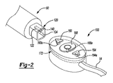
[0032]継続して図1を参照して、およびさらに図2および3を参照して、遠隔装置100をさらに詳細に考察する。図2および図3により詳細に示されるように、遠隔装置100が器具50に取り外し可能に接続され得る。しかし、コントローラ100が器具50に堅固に接続され得る。種々の実施形態で、コントローラ100は、器具50に堅固に接続される場合、使用者30により器具から外されるまで器具50を基準として動くことがない。
[0032] Continuing with reference to FIG. 1, and with further reference to FIGS. 2 and 3, the
[0033]堅固な接続を補助するために、器具50が、外側壁122および内側壁124を有する雄型コネクタ120などの接続部分を有することができる。外側壁122が正方形形状などの非円形の幾何形状を有することができる。正方形形状は、器具50を基準としたコントローラ100の回転を阻止または排除するのを補助することができる。遠隔装置100が、図3に具体的に示されるように、内壁132を有する雌型コネクタ130を有する対合コネクタを有することができる。雌型コネクタ130が遠隔装置100のハウジング136内にある凹部として形成され得る。ハウジング136が外側壁または外側表面138を有することができ、その中に雌型接続部分130が形成され得る。雄型接続部分120および雌型接続部分130が器具50と遠隔装置100との間に堅固な物理的接続を形成する。したがって、雌型コネクタ130が、回転方向および軸方向の堅固な接続を維持するのを補助するために雄型コネクタ120に対して相補的な形状を有することができる。しかし、選択される場合、接続部が、両方のコネクタ部分の形状が円形であることなどにより、回転を可能とし得る。
[0033] To assist in a secure connection, the instrument 50 may have a connection portion, such as a
[0034]接続部分120、130または他の部分を介して電気接続部または導電性接続部が作られ得る。例えば、器具50が、内側壁124と一体であるかまたは内側壁124の上にある雌型導電性接続部分140を形成することができる。内側壁124が、器具50の種々の部分に接続されるための1つまたは複数の導体を有することができ、両極性のまたは多極式の刺激のための複数の接続部などを提供する。遠隔装置100が、雌型接続部130の中に雄型導電性コネクタ144を有することができる。雄型導電性コネクタ144が、バナナプラグまたはクリップなどの、選択される雄型接続部として形成され得る。雄型コネクタ144が、器具50上の雌型コネクタ140との導電性接続部を作ることができる。雄型コネクタ144がさらに、遠隔装置100をモニタリング組立体20に接続する導体54に電気的に接続され得る。導体54が、遠隔装置組立体20に対しての遠隔装置100の物理的接続を実現する。したがって、器具50が遠隔装置組立体20に電気的におよび物理的に接続され得、それによりモニタリングシステム16内における使用者30による器具50の動作を実現する。
[0034] Electrical connections or conductive connections may be made via
[0035]遠隔制御装置100が、音声入力、および物理的入力などを含めた、多様な制御オプションを有することができる。例えば、遠隔制御装置100が、第1のプッシュボタン160、第2のプッシュボタン164、および第3のプッシュボタン168などの、1つまたは複数のプッシュボタンを有することができる。プッシュボタン160、164、および168の各々が、ボタンの下方に配置されるが、ハウジング136内に配置される印刷回路基板(PCB:printed circuit board)172上のボタンに関連付けられるそれぞれのスイッチを作動させるためにハウジング136を基準として動くような物理的なボタンまたは部材であってよい。PCB172が、それぞれのボタン160、168、および164に対応する電気スイッチ160a、168a、164aを有することができる。PCB172が、各々のスイッチ160a、164a、および168aから導体54までの電気接続部または導電性接続部を有することができる。したがって、モニタリング組立体20を制御するためにおよび/またはモニタリング組立体20を動作させるために、それぞれのスイッチ160a、164a、および168aからの信号がモニタリング組立体20に送られ得る。機械式トグルスイッチ、タッチ感応部分(例えば、容量性表面)、ジョイスティック、トラックボール、またはローラーボタン(例えば、コンピュータマウス上にある中央回転ボタン(center rolling button))などの、他の適切なスイッチが提供され得ることが理解されよう。
[0035] The
[0036]さらに、任意適切な数の入力ボタンまたは入力部分が遠隔装置100と共に提供され得ることが理解されよう。したがって、3つのボタン160、164、168を有することは単に例示である。さらに、これらのボタンのうちの2つ以上のボタンを同時に押すかまたは作動させることにより、ボタン160、164、168のうちの任意の1つのボタンを個別に押し下げるのとは異なりまた明確に区別される手法で、モニタリング組立体20を動作させることができる。さらに、選択される時間量でボタンのうちの任意の1つのボタンを順序通りに動作させるかまたは押し下げることにより(例えば、第1のボタンを押し下げ、第1のボタンの2秒の範囲内で第2のボタンを押し下げることにより)、別の異なる手法でモニタリング組立体20を動作させることができる。
[0036] Further, it will be appreciated that any suitable number of input buttons or portions may be provided with the
[0037]種々の実施形態で、モニタリングシステム20が、神経36に刺激を提供するのに、および接点40などを介して筋肉70などの中での誘発される反応に関する信号を受信するのに、使用され得る。したがって、使用者30が、神経36に刺激パルスを手動で提供すること、刺激パルスの振幅を変更すること、または刺激パルスの周波数を変更すること、などのために、遠隔制御装置100を動作させることができる。種々の実施形態によると、遠隔制御装置100が刺激電流を増大および/または減少させるように動作させられ得る。例えば、第1のボタン160が刺激電流を増大させるように動作させられ得、対して第2のボタン164が刺激電流を減少させるように動作させられ得る。ボタンが、選択される動作を示すための視覚的な印を有することができる。例えば、第1のボタン160が、器具50の方向などの概して「上方」を指す矢印または三角形として形成され得る。第2のボタン164が、動作中に減少を示すのを補助するために、器具50から離れる「下方」を指す矢印または三角形などの視覚的な表示を有することができる。第3のボタン168が、モニタリング組立体20の電流動作を切り替えるのに使用され得る、メニュー選択、確認、または他の汎用の入力などの、選択ボタンであってよい。
[0037] In various embodiments, the
[0038]遠隔装置100がさらに、モニタリング組立体20からの音声出力または音声メッセージを増大または減少させることなどのために、モニタリング組立体20を制御するのに使用され得る。やはり、第1のボタン160がボリュームを増大させるのに使用され得、対して第2のボタン164がボリュームを減少させるのに使用され得る。第3のボタン168が、種々の制御可能なオプションを介して、刺激電流の増大および減少ならびにモニタリング組立体20からのメッセージボリュームの増大および減少の間などでの、サイクルを行うのに使用され得る。
[0038] The
[0039]遠隔装置100がさらに、情報を収集するように、あるいはモニタリング組立体20によって受信または表示されている情報を保存するように、動作するのに使用され得る。やはり、上で考察したように、電極40が神経36の刺激による誘発された反応を受信することができる。誘発される反応が表示デバイス22上に表示され得るかまたは使用者30に対してのメッセージとして他の形で提示され得る。遠隔装置100が、モニタリング組立体20によってその時点で表示されているかまたは表されている情報のスナップショット(例えば、スクリーンショット)を取得または記録するように動作させられ得る。例えば、表示デバイス22が、知覚または感知された誘発される反応に関するグラフを表示することができる。表示デバイス22のスクリーンショットを取得することにより、電極40からモニタリング組立体20によって受信された選択される信号を使用者30が記録することが可能となる。使用者30が、一定の時間の経過後などにおいて、後で取得される信号または後で受信される信号と比較するために、記録されたスクリーンショットを使用することができる。さらに、記録されたスクリーンショットがその後の訓練の補助として使用され得る。
[0039] The
[0040]遠隔装置100がさらに、閾値を設定または制御するのに使用され得る。閾値は刺激電流および/または刺激電圧に関連してよい。さらに、閾値は電極40のところで受信される反応または受信される信号に関連してよい。制御の閾値が、電極40により受信される信号として特定される波形に関する上限または下限を設定することができる。
[0040] The
[0041]遠隔制御装置100がさらに、選択されるシステムを動作させるために動作させられ得る。例えば、モニタリング組立体20が、継続的なまたは自動のパルスシステムと共に動作させられ得る。例えば、自動式周期的刺激(automatic periodic stimulation)(Medtronic,Inc.によって販売されているAPS(登録商標)のStimulation System)が神経36に接続され得る。遠隔制御装置100が、自動式周期的刺激システムを介して周期的刺激を動作させるのに使用され得る。例えば、刺激電流を調整することが、上で考察したものと同様に、電極を介して行われ得る。さらに、APS(登録商標)のMonitoring Systemは、周期的刺激からの基準値としての誘発される反応(baseline evoked response)と、基準値からの逸脱に関する警報条件とを判断することなどの、種々の特徴を有することができる。遠隔制御装置100が、基準値の判断中にモニタリングシステム20を制御することおよび/または基準値の判断を開始すること(例えば、基準値を特定するための開始時間および終了時間を入力すること、ボリュームを変更することおよび/または提示されている信号(例えば、誘発されて感知された反応に関する周期的発信音)を消すこと、基準値からの逸脱に関する警報条件を変更または制御すること、ならびにAPS(登録商標)のMonitoring Systemの他の適切な特徴)のために使用され得る。したがって、遠隔制御装置は、モニタリングシステム16内のモニタリング組立体20の種々の特徴を動作させるのに使用され得る。
[0041] The
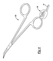
[0042]図4を参照すると、遠隔装置100が任意適切な器具に相互接続され得ることが理解されよう。例えば、器具は刺激電極鉗子(stimulating electrode forceps)200であってよく、遠隔装置100の雌型接続部分130に相互接続されることになる器具50の雄型コネクタ120と同様の接続部を有することができる。鉗子200が、神経36および/または他の組織部分の近くあるいは神経36および/または他の組織部分のところなどで、被験者34の種々の部分に接触するための1つまたは複数の接触電極を有することができる。
[0042] Referring to FIG. 4, it will be appreciated that the
[0043]しかし、遠隔装置100が、シングルチップのプローブまたはデュアルチップの鉗子のいずれか、あるいは他の適切な器具などの、選択される器具に接続され得ることが理解されよう。さらに、遠隔装置100が、第1の器具に接続され、第1の器具50から外され、さらにその後で第2の器具に接続され得る、ことが理解されよう。この場合、遠隔装置は第2の器具200から外されて第1の器具50に再接続され得る。さらに、器具のキットが任意適切な数の器具を有することができ、遠隔装置100が、選択される回数だけ、別の器具に接続されたり、別の器具から外されたり、別の器具に再接続されたりされ得ることが理解されよう。
[0043] However, it will be appreciated that the
[0044]遠隔装置100は器具50、200に実質的に直接に接続され得、それにより使用者30がそれぞれの器具50、200を把持する間における使用者30による遠隔装置の動作を容易にするのを可能にする。使用者30が、器具50、200の両方および/または遠隔装置100を操作するために一方の手または両方の手30a、30bを使用することができる。使用者30が、モニタリング組立体20を制御することを目的として、ボタン160、164、168などの部を押し下げるかまたは動作させるために一方の手または両方の手の指を使用することができる。例えば、第1のボタン160を押すのに、1つの指のみ(例えば、一方の手の指)が使用され得る。上述したように、第1のボタンを押すことにより、刺激電流を増大させることができる。
[0044] The
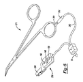
[0045]しかし、種々の実施形態によると、図5に示されるように、遠隔制御装置250が、器具接続コネクタ260を含めた、コネクタ54と同様の、コネクタを介して接続され得る。器具接続コネクタ260が、第2の接続部分264に接続される第1の接続部分262を有することができる。第2の接続部分264が器具270まで延在して器具270に接続され得る。器具270は上で考察した器具200と同様のものであってよいか、または上で考察した器具50と同様のものであってもよい。
[0045] However, according to various embodiments, as shown in FIG. 5, a
[0046]コネクタ260が、遠隔装置250を器具270から一定の距離のところに配置するのを可能にする。例えば、遠隔装置250が、クリップ280などを含めた、ホルダに接続され得る。クリップ280が、無菌布(sterile draping)(例えば、被験者34の上に配置されるかまたは被験者34の近くの部分の上に配置される)などの選択される部分に、または使用者30の衣服に、クリップ留めされ得、それにより使用者30の近くまたは使用者の30のところにかつ患者34から離れたところに遠隔装置250を配置することができる。この場合、使用者30が一方のまたは両方の手30a、30bを動かして遠隔装置250を動作させることができる。
[0046] A connector 260 allows the
[0047]遠隔装置250は遠隔装置100と同様のものであってよいかまたは同じものであってよく、第1のボタン160と、第2のボタン164と、第3のボタン168とを有する。さらに、遠隔装置250は、上で考察したものを含めた、任意適切な入力部分を有することができる。しかし、遠隔装置250は使用者30による動作のために好都合で有利であるロケーションに配置され得る。器具コネクタ260が導体54を介して非無菌フィールド110内のモニタリング組立体20に接続され得る。器具コネクタ260が導体54に相互接続され得、および/またはモニタリング組立体20に直接に接続され得る。器具接続部分260は、器具270から遠くにあって離れている選択されるロケーションのところに遠隔装置250を配置するのを可能にするために提供され得る。したがって、遠隔装置250が使用者30による動作のために器具270から離れて配置され得ることが理解されよう。しかし、遠隔装置100は、使用者30によって動作させられることになる選択される器具に直接に接続され得る。
[0047] The
[0048]さらに、遠隔装置250が導体260と直列に配置され得ることが理解されよう。遠隔装置250は器具200または器具270に接続される必要はなく、それでも、導体260に接続される別個の導体上にある必要もない。したがって、遠隔装置250は器具270から一定の距離のところに配置され得るが、導体260などを用いて、器具270に電気的に接続され得る。
[0048] Further, it will be appreciated that the
[0049]さらに、クリップ280が遠隔装置250に堅固に接続される必要がない。例えば、クリップ280は導体260に接続され得る。この場合、クリップ280は、上で考察したように、外科医30などの対象物に接続され得、ここでは導体260が外科医30の近くで遠隔装置250を維持するのを補助することになる。したがって、クリップ280は遠隔装置250の一部分として形成される必要がない。
[0049] Further, the
[0050]種々の実施形態によると、ディスプレイ300が遠隔装置100または遠隔装置250の上に含まれ得る。例えば、図6に示されるように、遠隔装置100’の上のディスプレイ300が外科医30に視認可能となり得る。遠隔装置100’は、スクリーン300を追加することを除いて、遠隔装置100と実質的に同様のものであってよいかまたは同じものであってよい。スクリーン300は、液晶ディスプレイ、発光ダイオードディスプレイなどの、任意適切なディスプレイであってよい。ディスプレイ300はまた、外科医30からの直接の入力を可能にすることができ、ならびに/または他のスイッチ160、164、および168を用いて変更され得る選択項目の表示を可能にすることができる。直接の入力はタッチ感応スクリーンを用いるものであってよく、対して他の入力は、ボタン160、164、168を用いて選択され得る。
[0050] According to various embodiments, a
[0051]ディスプレイ300が、モニタリング組立体20のその時点の動作などの、選択される情報を外科医30に対して表示することができる。その時点の動作には、刺激が行われているか否か、刺激の種類、刺激電流または刺激電圧などが含まれてよい。ディスプレイ300はまた、START、STOP、CONTINUOUS、刺激の増大、刺激の減少、などの、制御オプションを表示することができる。
[0051] The
[0052]スクリーン300はまた、上で考察した手法と同様の手法で、モニタリング組立体20を動作させるように遠隔装置上で使用され得る。例えば、選択される動作の種類が表示され得、つまり外科医30によって選択され得る。図6に示されるように、ディスプレイが、「STOP」、または刺激を止めることに関連するアイコンを表示することができ、使用者30の選択に応じて、STOPアイコンが下線を用いて強調され得る。外科医30が、タッチスクリーンを介して、またはボタン160、164、168などを用いる選択を介して、STOPを選択することができる。このように、システムは外科医30による選択に応じて動作することができる。したがって、ディスプレイ300は、モニタリング組立体20を制御するために、単独でまたは他のボタンとの組み合わせで、遠隔装置100’上で使用され得る。
[0052] The
[0053]ディスプレイ300は、プロセッサ26によってアクセスされる保存されている指示に基づいて種々のアイコンおよび通信内容を表示することができる。例えば、プロセッサ26が、ディスプレイ300上で、刺激を開始および停止するためのコマンドの選択項目を表示するための指示を実行することができる。この場合、使用者が、表示されるアイコンのうちの1つのアイコンを選択または強調するために(例えば、ディスプレイ300上に表示される下線を用いる)、ボタン160などを用いて、遠隔装置100’を動作させることができる。この場合、使用者30が、ボタン168を押し下げることなどにより、強調されているまたは選択されているアイコンを選択することにより、コマンドを入力することができる。当業者には理解されるような形でこのような指示が選択されるアルゴリズムまたは指示に組み込まれ得ることを理解されよう。
[0053] The
[0054]種々の実施形態によると、遠隔装置100などの遠隔装置は、モニタリング組立体20と通信するために導体54に物理的に接続される必要はない。上で考察したように、導体54が、遠隔制御装置100からの信号をモニタリング組立体20まで伝達すること、および/またはモニタリング組立体20からの刺激信号を器具50を通して、神経36などの、患者34まで供給することを可能にする。しかし、遠隔装置100は、モニタリング組立体20と通信するために、当技術分野で一般に知られるような、無線通信システムまたは無線通信部分を有することができる。しかし、遠隔装置100は上で考察したように動作させられ得、外科医30からの指示が、無線トランスミッションまたは電波放送(OTA:over the air)トランスミッションを用いてモニタリング組立体20に通信させられ得る。また、モニタリング組立体20の動作に関するモニタリング組立体20からのトランスミッションも、遠隔装置100までの無線トランスミッションまたはOTAトランスミッションであってよい。電極に刺激を提供するために、導体54または他の選択される導体が、器具200などの選択される器具に接続され得る。モニタリング組立体20の制御、または少なくとも選択される制御は、モニタリング組立体20と無線通信する遠隔装置100を用いるものであってよい。
[0054] According to various embodiments, a remote device, such as
[0055]例示の実施形態は、本開示を徹底的なものとするように、および本開示により当業者に本範囲を完全に伝えることができるように、提供されるものである。本開示の実施形態を完全に理解するのを可能にするために、具体的な構成要素、デバイス、および方法の例などの、多数の具体的な細部が記述される。具体的な細部が採用される必要がないこと、例示の実施形態が多くの異なる形態で具体化され得ること、ならびにいずれも本開示の範囲を限定するものとして解釈されるべきではないこと、が当業者には明白であろう。いくつかの例示の実施形態では、よく知られたプロセス、よく知られたデバイス構造、およびよく知られた技術は詳細には説明されない。 [0055] Illustrative embodiments are provided so that this disclosure will be thorough, and will fully convey the scope of the disclosure to those skilled in the art. Numerous specific details are described, such as examples of specific components, devices, and methods, to enable a thorough understanding of embodiments of the present disclosure. That specific details need not be employed, that the exemplary embodiments can be embodied in many different forms, and that none should be construed as limiting the scope of the disclosure. It will be apparent to those skilled in the art. In some exemplary embodiments, well-known processes, well-known device structures, and well-known techniques are not described in detail.
[0056]実施形態の上記の記述は例示および説明を目的として提供されるものである。これは、包括的であること、また本開示を限定するものであることは意図されていない。特定の実施形態の個別の要素または特徴は、概して、これらの特定の実施形態のみに限定されず、むしろ、適用可能である場合、相互交換可能であり、具体的に示されたりまたは説明されたりしていない場合でも選択される実施形態で使用され得る。また、これらは多くの手法で変化し得る。このような変化は本開示を逸脱するものとしてみなされず、このようなすべての修正形態が本開示の範囲内に含まれることが意図されている。 [0056] The above description of the embodiments is provided for purposes of illustration and description. This is not intended to be exhaustive or to limit the present disclosure. The individual elements or features of particular embodiments are generally not limited to only these particular embodiments, but rather are interchangeable and, where applicable, specifically shown or described. If not, it can be used in selected embodiments. They can also change in many ways. Such changes are not to be regarded as a departure from the present disclosure, and all such modifications are intended to be included within the scope of the present disclosure.
Claims (22)
刺激電圧を発生させるように構成される刺激システムと、
前記無菌フィールド内で前記患者の近くに配置されるように構成される刺激器具と、
前記刺激器具に導電的に接続され、前記無菌フィールド内で前記患者の近くに配置されるように構成されるコントローラと、
前記刺激システムおよび前記コントローラに物理的に接続される導体と
を備え、
前記コントローラが、前記刺激システムの少なくとも1つの動作を制御するための入力部を有する、刺激モニタリングシステム。 A stimulation monitoring system disposed in a non-sterile field outside the sterile field to stimulate at least a portion of the patient within the sterile field,
A stimulation system configured to generate a stimulation voltage;
A stimulating device configured to be placed near the patient in the sterile field;
A controller that is conductively connected to the stimulation device and configured to be placed in the sterile field near the patient;
A conductor physically connected to the stimulation system and the controller;
A stimulus monitoring system, wherein the controller has an input for controlling at least one operation of the stimulus system.
前記少なくとも1つのスイッチが、前記無菌フィールド内で使用者によって動作させられるように構成される、請求項1に記載の刺激モニタリングシステム。 The input unit has at least one switch;
The stimulus monitoring system of claim 1, wherein the at least one switch is configured to be operated by a user within the sterile field.
前記プッシュボタンスイッチが、前記指によって直接に係合されるように前記ハウジングから延在するように構成される第1の部分と、前記ハウジング内に配置される印刷回路基板に固定されるトグルスイッチを有する第2の部分とを有し、
前記トグルスイッチが、前記刺激システムに送られる信号を発生させるように構成され、
前記刺激システムが、前記刺激システムの少なくとも1つの動作を制御するために前記信号を受信するように構成されるプロセッサを有する、請求項3に記載の刺激モニタリングシステム。 The controller has an outer housing;
A first portion configured to extend from the housing such that the push button switch is directly engaged by the finger, and a toggle switch secured to a printed circuit board disposed within the housing; A second part having
The toggle switch is configured to generate a signal that is sent to the stimulation system;
The stimulus monitoring system of claim 3, wherein the stimulus system comprises a processor configured to receive the signal to control at least one operation of the stimulus system.
前記刺激システムの前記少なくとも1つの動作が、刺激周期を変更すること、刺激電圧を変更すること、刺激を開始すること、刺激を止めること、スクリーンショットを捕捉すること、閾値を制御すること、またはメッセージボリュームを変更すること、のうちの少なくとも1つを含む、請求項1から4までのいずれか一項に記載の刺激モニタリングシステム。 The stimulation system comprises a processor configured to receive a signal from the input to control at least one operation of the stimulation system;
The at least one operation of the stimulation system is changing a stimulation cycle, changing a stimulation voltage, starting a stimulation, stopping a stimulation, capturing a screenshot, controlling a threshold, or 5. The stimulus monitoring system according to any one of claims 1 to 4, comprising at least one of changing the message volume.
前記導体が前記無菌フィールド内の前記コントローラから前記非無菌フィールド内の前記刺激システムまで延在する、請求項1から5までのいずれか一項に記載の刺激モニタリングシステム。 The controller has a housing rigidly connected to the stimulator;
The stimulation monitoring system according to any one of claims 1 to 5, wherein the conductor extends from the controller in the sterile field to the stimulation system in the non-sterile field.
前記ディスプレイが、前記刺激システムのその時点の動作に関する情報、および/または前記使用者によって入力されることになるコマンドを示すように構成可能である、請求項1から7までのいずれか一項に記載の刺激モニタリングシステム。 The controller has a display;
8. The display according to any one of the preceding claims, wherein the display is configurable to show information regarding the current operation of the stimulation system and / or commands to be entered by the user. The stimulus monitoring system described.
前記刺激器具に導電的に接続され、前記無菌フィールド内で前記患者の近くに配置されるように構成されるコントローラと、
使用者による作動時に前記刺激システムに信号を送信するための、前記コントローラと共に形成される入力部分と、
前記無菌フィールド内の前記コントローラと前記非無菌フィールド内の前記刺激システムとの間の接続通信部分と
を備え、
前記入力部分からの前記信号が前記刺激システムの少なくとも1つの動作を制御するためのものである、刺激モニタリングシステム。 A stimulation monitoring system comprising a stimulation system disposed in a non-sterile field outside the sterile field for stimulating at least a portion of a patient using a stimulation device within the sterile field,
A controller that is conductively connected to the stimulation device and configured to be placed in the sterile field near the patient;
An input portion formed with the controller for transmitting a signal to the stimulation system upon actuation by a user;
A communication connection between the controller in the sterile field and the stimulation system in the non-sterile field;
A stimulation monitoring system, wherein the signal from the input portion is for controlling at least one operation of the stimulation system.
前記刺激器具が、前記無菌フィールド内で前記患者の近くに配置されるように構成される刺激伝導部分を有し、
前記コントローラが、前記刺激器具に堅固に接続される、請求項9に記載の刺激モニタリングシステム。 The stimulation system comprises a stimulation generator having a processor and configured to generate a stimulation current;
The stimulation device has a stimulation conducting portion configured to be positioned near the patient in the sterile field;
The stimulation monitoring system of claim 9, wherein the controller is rigidly connected to the stimulation device.
前記刺激器具が、前記無菌フィールド内で前記患者の近くに配置されるように構成される刺激伝導部分を有し、
前記コントローラが、前記無菌フィールド内の前記刺激器具から一定の距離で前記導体に接続され、
前記導体が、前記コントローラから前記刺激器具まで、および前記コントローラから前記刺激システムまで、延在する、請求項9に記載の刺激モニタリングシステム。 The stimulation system comprises a stimulation generator having a processor and configured to generate a stimulation current;
The stimulation device has a stimulation conducting portion configured to be positioned near the patient in the sterile field;
The controller is connected to the conductor at a distance from the stimulator in the sterile field;
The stimulation monitoring system of claim 9, wherein the conductor extends from the controller to the stimulation device and from the controller to the stimulation system.
前記少なくとも1つのスイッチが、前記無菌フィールド内で前記使用者によって動作させられるように構成される、請求項9から11までのいずれか一項に記載の刺激モニタリングシステム。 The input part has at least one switch;
12. A stimulus monitoring system according to any one of claims 9 to 11, wherein the at least one switch is configured to be operated by the user within the sterile field.
前記少なくとも1つのスイッチが、前記使用者の指によって直接に係合されるように前記ハウジングから延在するように構成される第1の部分と、前記ハウジング内に配置される印刷回路基板に固定されるトグルスイッチを有する第2の部分とを有するプッシュボタンスイッチを有し、
前記トグルスイッチが、前記刺激システムに送られる信号を発生させるように構成され、
前記刺激システムが、前記刺激システムの少なくとも1つの動作を制御するために前記信号を受信するように構成されるプロセッサを有する、請求項12に記載の刺激モニタリングシステム。 The controller has an outer housing;
A first portion configured to extend from the housing to be directly engaged by the user's finger and fixed to a printed circuit board disposed within the housing A push button switch having a second portion with a toggle switch to be
The toggle switch is configured to generate a signal that is sent to the stimulation system;
The stimulation monitoring system of claim 12, wherein the stimulation system comprises a processor configured to receive the signal to control at least one operation of the stimulation system.
前記刺激システムの前記少なくとも1つの動作が、刺激周期を変更すること、刺激電圧を変更すること、刺激を開始すること、刺激を止めること、スクリーンショットを捕捉すること、閾値を調整すること、またはメッセージボリュームを変更すること、のうちの少なくとも1つを含む、請求項9から13までのいずれか一項に記載の刺激モニタリングシステム。 The stimulation system comprises a processor configured to receive the signal from the input portion;
The at least one operation of the stimulation system is changing a stimulation cycle, changing a stimulation voltage, starting a stimulation, stopping a stimulation, capturing a screenshot, adjusting a threshold, or 14. The stimulus monitoring system according to any one of claims 9 to 13, comprising at least one of changing message volume.
前記刺激器具を無菌フィールド内に配置するステップと、
前記刺激システムを有する前記刺激モニタリングシステムを、前記無菌フィールドの外にある非無菌フィールド内に配置するステップと、
コントローラを前記無菌フィールド内の前記刺激器具に物理的に接続するステップと、
前記コントローラを前記非無菌フィールド内にある前記刺激モニタリングシステムに物理的に接続するステップと、
前記無菌フィールド内で前記コントローラを用いて前記刺激システムの少なくとも1つの動作を制御するステップと
を含む、方法。 A method for controlling a stimulation monitoring system having a stimulation system via a stimulation device, comprising:
Placing the stimulator in a sterile field;
Placing the stimulus monitoring system with the stimulus system in a non-sterile field outside the sterile field;
Physically connecting a controller to the stimulation device in the sterile field;
Physically connecting the controller to the stimulus monitoring system in the non-sterile field;
Controlling at least one operation of the stimulation system with the controller in the sterile field.
前記刺激システムの少なくとも1つの動作を制御するステップが、刺激周期を変更するステップ、刺激電圧を変更するステップ、スクリーンショットを捕捉するステップ、閾値を調整するステップ、またはメッセージボリュームを変更するステップ、のうちの少なくとも1つのステップを含む、請求項20に記載の方法。 The stimulation system comprises a processor configured to receive the signal from the controller;
Controlling at least one operation of the stimulation system comprises changing a stimulation cycle, changing a stimulation voltage, capturing a screenshot, adjusting a threshold, or changing a message volume. 21. The method of claim 20, comprising at least one of the steps.
Applications Claiming Priority (3)
| Application Number | Priority Date | Filing Date | Title |
|---|---|---|---|
| US15/269,051 | 2016-09-19 | ||
| US15/269,051 US10849517B2 (en) | 2016-09-19 | 2016-09-19 | Remote control module for instruments |
| PCT/US2017/051825 WO2018053295A1 (en) | 2016-09-19 | 2017-09-15 | Remote control module for instruments |
Publications (2)
| Publication Number | Publication Date |
|---|---|
| JP2019532704A true JP2019532704A (en) | 2019-11-14 |
| JP2019532704A5 JP2019532704A5 (en) | 2020-11-12 |
Family
ID=60002012
Family Applications (1)
| Application Number | Title | Priority Date | Filing Date |
|---|---|---|---|
| JP2019515506A Pending JP2019532704A (en) | 2016-09-19 | 2017-09-15 | Remote control module for instruments |
Country Status (8)
| Country | Link |
|---|---|
| US (2) | US10849517B2 (en) |
| EP (1) | EP3515304A1 (en) |
| JP (1) | JP2019532704A (en) |
| KR (1) | KR20190049860A (en) |
| CN (1) | CN109963504A (en) |
| AU (1) | AU2017326105A1 (en) |
| CA (1) | CA3037298A1 (en) |
| WO (1) | WO2018053295A1 (en) |
Cited By (1)
| Publication number | Priority date | Publication date | Assignee | Title |
|---|---|---|---|---|
| JP7421832B1 (en) | 2023-06-21 | 2024-01-25 | メディジェンス合同会社 | Stethoscope |
Families Citing this family (4)
| Publication number | Priority date | Publication date | Assignee | Title |
|---|---|---|---|---|
| US10123731B2 (en) | 2014-08-08 | 2018-11-13 | Medtronic Xomed, Inc. | Wireless sensors for nerve integrity monitoring systems |
| US10039915B2 (en) | 2015-04-03 | 2018-08-07 | Medtronic Xomed, Inc. | System and method for omni-directional bipolar stimulation of nerve tissue of a patient via a surgical tool |
| US20220257940A1 (en) | 2021-02-18 | 2022-08-18 | Medtronic Xomed, Inc. | System and Method for Stimulation of Nerve Tissue |
| US20220265245A1 (en) * | 2021-02-23 | 2022-08-25 | Bard Access Systems, Inc. | Computing Device Controller System |
Citations (5)
| Publication number | Priority date | Publication date | Assignee | Title |
|---|---|---|---|---|
| JP2008508049A (en) * | 2004-07-29 | 2008-03-21 | ウォーソー・オーソペディック・インコーポレーテッド | Stimulator handpiece for evoked potential monitoring system |
| JP2010515487A (en) * | 2007-01-09 | 2010-05-13 | エヌディーアイ メディカル, エルエルシー | Intraoperative stimulation system and method |
| US20110028860A1 (en) * | 2009-07-29 | 2011-02-03 | Fabrice Chenaux | Neuromonitoring system with wireless instrumentation |
| WO2015069962A1 (en) * | 2012-11-06 | 2015-05-14 | Nuvasive, Inc. | Neuroophysiologic monitoring during spine surgery |
| JP2015513988A (en) * | 2012-04-09 | 2015-05-18 | エシコン・エンド−サージェリィ・インコーポレイテッドEthicon Endo−Surgery,Inc. | Surgical instrument with nerve detection function |
Family Cites Families (122)
| Publication number | Priority date | Publication date | Assignee | Title |
|---|---|---|---|---|
| DE2831313A1 (en) | 1978-07-17 | 1980-02-07 | Draegerwerk Ag | DEVICE FOR SUPPORTING BREATHING AND / OR ARTIFICIAL VENTILATION |
| SE9601387D0 (en) | 1996-04-12 | 1996-04-12 | Siemens Elema Ab | Device for monitoring measuring electrodes for recording physiological measurement signals and their leads |
| US6017354A (en) * | 1996-08-15 | 2000-01-25 | Stryker Corporation | Integrated system for powered surgical tools |
| US6029090A (en) | 1997-01-27 | 2000-02-22 | Herbst; Ewa | Multi-functional electrical stimulation system |
| US20030171747A1 (en) | 1999-01-25 | 2003-09-11 | Olympus Optical Co., Ltd. | Medical treatment instrument |
| US6496705B1 (en) | 2000-04-18 | 2002-12-17 | Motorola Inc. | Programmable wireless electrode system for medical monitoring |
| US6441747B1 (en) | 2000-04-18 | 2002-08-27 | Motorola, Inc. | Wireless system protocol for telemetry monitoring |
| WO2002082982A1 (en) | 2001-04-18 | 2002-10-24 | Cochlear Limited | Method and apparatus for measurement of evoked neural response |
| US10835307B2 (en) * | 2001-06-12 | 2020-11-17 | Ethicon Llc | Modular battery powered handheld surgical instrument containing elongated multi-layered shaft |
| US6932816B2 (en) | 2002-02-19 | 2005-08-23 | Boston Scientific Scimed, Inc. | Apparatus for converting a clamp into an electrophysiology device |
| US7236822B2 (en) | 2002-03-22 | 2007-06-26 | Leptos Biomedical, Inc. | Wireless electric modulation of sympathetic nervous system |
| EP1581999B1 (en) | 2002-12-20 | 2007-01-17 | Matsushita Electric Industrial Co., Ltd. | Gate driver, motor driving device including the gate driver, and apparatus equipped with the motor driving device |
| US7216001B2 (en) | 2003-01-22 | 2007-05-08 | Medtronic Xomed, Inc. | Apparatus for intraoperative neural monitoring |
| US7689292B2 (en) | 2003-02-27 | 2010-03-30 | Macosta Medical U.S.A., L.L.C. | Nerve stimulation functionality indicator apparatus and method |
| CN2610843Y (en) | 2003-04-22 | 2004-04-14 | 上海诺诚电气有限公司 | Scalp impedance detector |
| US7129836B2 (en) | 2003-09-23 | 2006-10-31 | Ge Medical Systems Information Technologies, Inc. | Wireless subject monitoring system |
| US7496407B2 (en) | 2003-12-23 | 2009-02-24 | Odderson Ib R | Nerve stimulator measuring device |
| US7869881B2 (en) | 2003-12-24 | 2011-01-11 | Cardiac Pacemakers, Inc. | Baroreflex stimulator with integrated pressure sensor |
| CA2455287A1 (en) | 2004-01-16 | 2005-07-16 | Francois Bellemare | Catheter for transdiaphragmatic pressure and diaphragm electromyogram recording using helicoidal electrodes |
| US7292886B1 (en) | 2004-01-20 | 2007-11-06 | Pacesetter, Inc. | Bifocal cardiac stimulation device and methods |
| US7359751B1 (en) * | 2004-05-05 | 2008-04-15 | Advanced Neuromodulation Systems, Inc. | Clinician programmer for use with trial stimulator |
| US20050267529A1 (en) | 2004-05-13 | 2005-12-01 | Heber Crockett | Devices, systems and methods for tissue repair |
| US20050261559A1 (en) | 2004-05-18 | 2005-11-24 | Mumford John R | Wireless physiological monitoring system |
| WO2006026482A2 (en) | 2004-08-25 | 2006-03-09 | Encore Medical Asset Corporation | Chiropractic table with continuous passive motion |
| US9247952B2 (en) | 2004-10-15 | 2016-02-02 | Amendia, Inc. | Devices and methods for tissue access |
| EP1656883A1 (en) | 2004-11-10 | 2006-05-17 | Universite Libre De Bruxelles | Portable device for measuring EMG signal |
| EP2409641B1 (en) * | 2005-02-02 | 2017-07-05 | NuVasive, Inc. | System for performing neurophysiologic assessments during spine surgery |
| JP2008529736A (en) | 2005-02-18 | 2008-08-07 | レイ シー ワシルースキー | Smart joint implant sensor |
| US20080214903A1 (en) | 2005-02-22 | 2008-09-04 | Tuvi Orbach | Methods and Systems for Physiological and Psycho-Physiological Monitoring and Uses Thereof |
| US10154792B2 (en) | 2005-03-01 | 2018-12-18 | Checkpoint Surgical, Inc. | Stimulation device adapter |
| US20060200023A1 (en) | 2005-03-04 | 2006-09-07 | Sdgi Holdings, Inc. | Instruments and methods for nerve monitoring in spinal surgical procedures |
| JP2008532713A (en) | 2005-03-18 | 2008-08-21 | ザ トラスティーズ オブ ザ スティーブンス インスティテュート オブ テクノロジー | Apparatus and method for diagnosing the cause of muscle pain |
| WO2006113394A2 (en) | 2005-04-15 | 2006-10-26 | Surgisense Corporation | Surgical instruments with sensors for detecting tissue properties, and systems using such instruments |
| US20060241725A1 (en) | 2005-04-25 | 2006-10-26 | Imad Libbus | Method and apparatus for simultaneously presenting cardiac and neural signals |
| US8068910B2 (en) | 2005-04-28 | 2011-11-29 | Medtronic, Inc. | Flexible tube sensor for sensing urinary sphincter pressure |
| US20060276702A1 (en) | 2005-06-03 | 2006-12-07 | Mcginnis William | Neurophysiological wireless bio-sensor |
| TW200704391A (en) | 2005-07-29 | 2007-02-01 | chang-an Zhou | Paste physical monitoring device, system and network |
| US8657814B2 (en) * | 2005-08-22 | 2014-02-25 | Medtronic Ablation Frontiers Llc | User interface for tissue ablation system |
| US8568317B1 (en) | 2005-09-27 | 2013-10-29 | Nuvasive, Inc. | System and methods for nerve monitoring |
| US8764654B2 (en) | 2008-03-19 | 2014-07-01 | Zin Technologies, Inc. | Data acquisition for modular biometric monitoring system |
| US20080077200A1 (en) | 2006-09-21 | 2008-03-27 | Aculight Corporation | Apparatus and method for stimulation of nerves and automated control of surgical instruments |
| US7993269B2 (en) | 2006-02-17 | 2011-08-09 | Medtronic, Inc. | Sensor and method for spinal monitoring |
| US20070282217A1 (en) | 2006-06-01 | 2007-12-06 | Mcginnis William J | Methods & systems for intraoperatively monitoring nerve & muscle frequency latency and amplitude |
| WO2008002917A2 (en) | 2006-06-27 | 2008-01-03 | Cyberkinetics Neurotechnology Systems, Inc. | Systems and methods for promoting nerve regeneration |
| US20100152811A1 (en) | 2006-06-30 | 2010-06-17 | Flaherty Christopher J | Nerve regeneration system and lead devices associated therewith |
| FI20065500A0 (en) | 2006-07-25 | 2006-07-25 | Mediracer Ltd | A method and apparatus for wirelessly controlling nerve response measurement |
| US20080071315A1 (en) | 2006-08-31 | 2008-03-20 | Tamara Colette Baynham | Integrated catheter and pulse generator systems and methods |
| AU2007293613A1 (en) | 2006-09-08 | 2008-03-13 | Ull Meter A/S | Method of utilising measurements of threshold of pain |
| US7605738B2 (en) | 2006-09-13 | 2009-10-20 | Advantest Corporation | A-D converter and A-D convert method |
| US7789833B2 (en) | 2006-11-16 | 2010-09-07 | Penrith Corporation | Integrated nerve stimulator and ultrasound imaging device |
| WO2008097407A2 (en) | 2006-12-18 | 2008-08-14 | Trillium Precision Surgical, Inc. | Intraoperative tissue mapping and dissection systems, devices, methods, and kits |
| US20100145178A1 (en) | 2007-01-23 | 2010-06-10 | Kartush Jack M | Nerve monitoring device |
| US8886280B2 (en) | 2007-01-23 | 2014-11-11 | The Magstim Company Limited | Nerve monitoring device |
| US7987001B2 (en) | 2007-01-25 | 2011-07-26 | Warsaw Orthopedic, Inc. | Surgical navigational and neuromonitoring instrument |
| US8374673B2 (en) | 2007-01-25 | 2013-02-12 | Warsaw Orthopedic, Inc. | Integrated surgical navigational and neuromonitoring system having automated surgical assistance and control |
| JP4773377B2 (en) | 2007-01-29 | 2011-09-14 | ルネサスエレクトロニクス株式会社 | COMMUNICATION SYSTEM, COMMUNICATION DEVICE, AND FLOW CONTROL METHOD |
| WO2008124079A1 (en) * | 2007-04-03 | 2008-10-16 | Nuvasive, Inc. | Neurophysiologic monitoring system |
| US8594779B2 (en) | 2007-04-30 | 2013-11-26 | Medtronic, Inc. | Seizure prediction |
| KR100877229B1 (en) | 2007-05-14 | 2009-01-09 | 가천의과학대학교 산학협력단 | Neural electronic interface device for motor and sensory controls of human body |
| US8295933B2 (en) | 2007-05-30 | 2012-10-23 | Medtronic, Inc. | Implantable medical lead including voiding event sensor |
| US20080306348A1 (en) | 2007-06-06 | 2008-12-11 | National Yang-Ming University | Miniature wireless apparatus for recording physiological signals of humans and use thereof |
| US8680986B2 (en) | 2007-08-01 | 2014-03-25 | Peter Costantino | System and method for facial nerve monitoring during facial surgery |
| US8926509B2 (en) | 2007-08-24 | 2015-01-06 | Hmicro, Inc. | Wireless physiological sensor patches and systems |
| WO2009051965A1 (en) | 2007-10-14 | 2009-04-23 | Board Of Regents, The University Of Texas System | A wireless neural recording and stimulating system for pain management |
| US9084550B1 (en) | 2007-10-18 | 2015-07-21 | Innovative Surgical Solutions, Llc | Minimally invasive nerve monitoring device and method |
| US7974702B1 (en) | 2008-01-10 | 2011-07-05 | Pacesetter, Inc. | Communication device, communication system and communication method for an implantable medical device |
| US20090182322A1 (en) | 2008-01-11 | 2009-07-16 | Live Tissue Connect, Inc. | Bipolar modular forceps modular arms |
| US9078671B2 (en) | 2008-04-17 | 2015-07-14 | Warsaw Orthopedic, Inc. | Surgical tool |
| ES2921476T3 (en) * | 2008-04-17 | 2022-08-26 | Bard Inc C R | Systems for breaking a sterile field for intravascular placement of a catheter |
| US20090299439A1 (en) | 2008-06-02 | 2009-12-03 | Warsaw Orthopedic, Inc. | Method, system and tool for surgical procedures |
| US9119533B2 (en) | 2008-10-07 | 2015-09-01 | Mc10, Inc. | Systems, methods, and devices having stretchable integrated circuitry for sensing and delivering therapy |
| US8428733B2 (en) | 2008-10-16 | 2013-04-23 | Medtronic, Inc. | Stimulation electrode selection |
| EP2358266A4 (en) | 2008-11-20 | 2012-10-03 | Bodymedia Inc | Method and apparatus for determining critical care parameters |
| US8515520B2 (en) | 2008-12-08 | 2013-08-20 | Medtronic Xomed, Inc. | Nerve electrode |
| US9084551B2 (en) | 2008-12-08 | 2015-07-21 | Medtronic Xomed, Inc. | Method and system for monitoring a nerve |
| US20100160731A1 (en) | 2008-12-22 | 2010-06-24 | Marc Giovannini | Ultrasound-visualizable endoscopic access system |
| US8126736B2 (en) | 2009-01-23 | 2012-02-28 | Warsaw Orthopedic, Inc. | Methods and systems for diagnosing, treating, or tracking spinal disorders |
| US9370654B2 (en) | 2009-01-27 | 2016-06-21 | Medtronic, Inc. | High frequency stimulation to block laryngeal stimulation during vagal nerve stimulation |
| US8989855B2 (en) | 2009-01-30 | 2015-03-24 | Medtronic Xomed, Inc. | Nerve monitoring during electrosurgery |
| US20100280568A1 (en) | 2009-04-30 | 2010-11-04 | Cherik Bulkes | Implantable High Efficiency Energy Transfer Module With Near-Field Inductive Coupling |
| US8233992B2 (en) | 2009-08-28 | 2012-07-31 | Boston Scientific Neuromodulation Corporation | Method and apparatus for determining relative positioning between neurostimulation leads |
| JP2013505080A (en) | 2009-09-21 | 2013-02-14 | メドトロニック,インコーポレイテッド | Waveform for electrical stimulation treatment |
| AU2010300373B2 (en) | 2009-10-02 | 2014-04-24 | Medtronic-Xomed, Inc. | Endotracheal tube apparatus |
| US8753333B2 (en) | 2010-03-10 | 2014-06-17 | Covidien Lp | System for determining proximity relative to a nerve |
| US8568312B2 (en) | 2010-03-12 | 2013-10-29 | MaryRose Cusimano Reaston | Electro diagnostic functional assessment unit (EFA-3) |
| US10631912B2 (en) | 2010-04-30 | 2020-04-28 | Medtronic Xomed, Inc. | Interface module for use with nerve monitoring and electrosurgery |
| US20130030257A1 (en) | 2010-05-14 | 2013-01-31 | Kai Medical, Inc. | Systems and methods for non-contact multiparameter vital signs monitoring, apnea therapy, apnea diagnosis, and snore therapy |
| CA2801333C (en) | 2010-06-04 | 2018-11-20 | University Health Network | Functional electrical stimulation device and system, and use thereof |
| US9149188B2 (en) | 2010-07-01 | 2015-10-06 | Shenzhen Mindray Bio-Medical Electronics Co. Ltd. | Systems and methods for synchronizing data received from multiple sensor modules in a patient monitor system |
| JP6060146B2 (en) | 2011-03-24 | 2017-01-11 | カリフォルニア インスティテュート オブ テクノロジー | Nerve stimulator |
| US10092349B2 (en) | 2011-05-04 | 2018-10-09 | The University Of Akron | Variable-frequency stimulator for electrosurgery |
| CN104080509B (en) | 2011-07-29 | 2017-09-08 | 米克伦设备有限责任公司 | The remote control that power or polarity for nerve stimulator are selected |
| US9579503B2 (en) | 2011-10-05 | 2017-02-28 | Medtronic Xomed, Inc. | Interface module allowing delivery of tissue stimulation and electrosurgery through a common surgical instrument |
| JP6133393B2 (en) | 2012-03-19 | 2017-05-24 | カーディアック ペースメイカーズ, インコーポレイテッド | System and method for monitoring nerve damage |
| US20150012066A1 (en) | 2012-03-22 | 2015-01-08 | Wendell Martin Underwood | Noninvasive delivery and control of stimulation signals |
| WO2013152094A1 (en) | 2012-04-03 | 2013-10-10 | Altec, Inc. | Disposable low-profile conformable biomedical sensor |
| WO2013151770A1 (en) | 2012-04-03 | 2013-10-10 | Carnegie Mellon University | Musculoskeletal activity recognition system and method |
| US9339655B2 (en) | 2012-06-30 | 2016-05-17 | Boston Scientific Neuromodulation Corporation | System and method for compounding low-frequency sources for high-frequency neuromodulation |
| US10314649B2 (en) | 2012-08-02 | 2019-06-11 | Ethicon Endo-Surgery, Inc. | Flexible expandable electrode and method of intraluminal delivery of pulsed power |
| EP2887986B1 (en) | 2012-08-22 | 2019-08-07 | ResMed Paris SAS | Breathing assistance system with speech detection |
| US20140058284A1 (en) | 2012-08-22 | 2014-02-27 | Innovative Surgical Solutions, Llc | Nerve monitoring system |
| US9180302B2 (en) * | 2012-08-31 | 2015-11-10 | Greatbatch Ltd. | Touch screen finger position indicator for a spinal cord stimulation programming device |
| US8892259B2 (en) | 2012-09-26 | 2014-11-18 | Innovative Surgical Solutions, LLC. | Robotic surgical system with mechanomyography feedback |
| US11877860B2 (en) * | 2012-11-06 | 2024-01-23 | Nuvasive, Inc. | Systems and methods for performing neurophysiologic monitoring during spine surgery |
| JP6145916B2 (en) | 2012-12-13 | 2017-06-14 | 株式会社国際電気通信基礎技術研究所 | Sensor device, measurement system, and measurement program |
| US9913594B2 (en) | 2013-03-14 | 2018-03-13 | Medtronic Xomed, Inc. | Compliant electrode for EMG endotracheal tube |
| US9044610B2 (en) | 2013-03-15 | 2015-06-02 | Pacesetter, Inc. | Systems and methods for providing a distributed virtual stimulation cathode for use with an implantable neurostimulation system |
| US10506944B2 (en) | 2013-03-16 | 2019-12-17 | Empatica Srl | Apparatus for electrodermal activity measurement with current compensation |
| WO2014197596A1 (en) | 2013-06-06 | 2014-12-11 | Doan Que T | System for delivering modulated sub-threshold therapy |
| US9339332B2 (en) | 2013-08-30 | 2016-05-17 | Medtronic Ardian Luxembourg S.A.R.L. | Neuromodulation catheters with nerve monitoring features for transmitting digital neural signals and associated systems and methods |
| US9622684B2 (en) | 2013-09-20 | 2017-04-18 | Innovative Surgical Solutions, Llc | Neural locating system |
| GB2519302B (en) | 2013-10-15 | 2016-04-20 | Gloucestershire Hospitals Nhs Foundation Trust | Apparatus for artificial cardiac stimulation and method of using the same |
| US10022090B2 (en) | 2013-10-18 | 2018-07-17 | Atlantic Health System, Inc. | Nerve protecting dissection device |
| CN105873506B (en) | 2013-11-07 | 2020-02-21 | 赛佛欧普手术有限公司 | System and method for detecting neurological function |
| US20160346544A1 (en) * | 2014-02-11 | 2016-12-01 | Rush University Medical Center | Self-contained, handheld bipolar cortical stimulator |
| US20150238260A1 (en) * | 2014-02-26 | 2015-08-27 | Covidien Lp | Surgical instruments including nerve stimulator apparatus for use in the detection of nerves in tissue and methods of directing energy to tissue using same |
| US20160015299A1 (en) | 2014-07-17 | 2016-01-21 | Elwha Llc | Use of epidermal electronic devices to measure orientation |
| US10123731B2 (en) | 2014-08-08 | 2018-11-13 | Medtronic Xomed, Inc. | Wireless sensors for nerve integrity monitoring systems |
| JP6805153B2 (en) | 2015-01-09 | 2020-12-23 | アクソニクス モジュレーション テクノロジーズ インコーポレイテッド | How to use with patient remote devices and associated neurostimulation systems |
| US20160206362A1 (en) * | 2015-01-21 | 2016-07-21 | Serene Medical, Inc. | Systems and devices to identify and limit nerve conduction |
| US20160262699A1 (en) | 2015-03-12 | 2016-09-15 | Andrew C. Goldstone | Endotracheal Tube for Nerve Monitoring |
| US10039915B2 (en) | 2015-04-03 | 2018-08-07 | Medtronic Xomed, Inc. | System and method for omni-directional bipolar stimulation of nerve tissue of a patient via a surgical tool |
-
2016
- 2016-09-19 US US15/269,051 patent/US10849517B2/en active Active
-
2017
- 2017-09-15 WO PCT/US2017/051825 patent/WO2018053295A1/en unknown
- 2017-09-15 AU AU2017326105A patent/AU2017326105A1/en not_active Abandoned
- 2017-09-15 CA CA3037298A patent/CA3037298A1/en not_active Abandoned
- 2017-09-15 KR KR1020197010841A patent/KR20190049860A/en not_active Application Discontinuation
- 2017-09-15 JP JP2019515506A patent/JP2019532704A/en active Pending
- 2017-09-15 CN CN201780071018.2A patent/CN109963504A/en active Pending
- 2017-09-15 EP EP17778021.0A patent/EP3515304A1/en active Pending
-
2020
- 2020-09-23 US US17/029,472 patent/US20210000363A1/en active Pending
Patent Citations (5)
| Publication number | Priority date | Publication date | Assignee | Title |
|---|---|---|---|---|
| JP2008508049A (en) * | 2004-07-29 | 2008-03-21 | ウォーソー・オーソペディック・インコーポレーテッド | Stimulator handpiece for evoked potential monitoring system |
| JP2010515487A (en) * | 2007-01-09 | 2010-05-13 | エヌディーアイ メディカル, エルエルシー | Intraoperative stimulation system and method |
| US20110028860A1 (en) * | 2009-07-29 | 2011-02-03 | Fabrice Chenaux | Neuromonitoring system with wireless instrumentation |
| JP2015513988A (en) * | 2012-04-09 | 2015-05-18 | エシコン・エンド−サージェリィ・インコーポレイテッドEthicon Endo−Surgery,Inc. | Surgical instrument with nerve detection function |
| WO2015069962A1 (en) * | 2012-11-06 | 2015-05-14 | Nuvasive, Inc. | Neuroophysiologic monitoring during spine surgery |
Cited By (1)
| Publication number | Priority date | Publication date | Assignee | Title |
|---|---|---|---|---|
| JP7421832B1 (en) | 2023-06-21 | 2024-01-25 | メディジェンス合同会社 | Stethoscope |
Also Published As
| Publication number | Publication date |
|---|---|
| US20210000363A1 (en) | 2021-01-07 |
| US10849517B2 (en) | 2020-12-01 |
| AU2017326105A1 (en) | 2019-04-11 |
| CA3037298A1 (en) | 2018-03-22 |
| WO2018053295A1 (en) | 2018-03-22 |
| CN109963504A (en) | 2019-07-02 |
| KR20190049860A (en) | 2019-05-09 |
| EP3515304A1 (en) | 2019-07-31 |
| US20180078161A1 (en) | 2018-03-22 |
Similar Documents
| Publication | Publication Date | Title |
|---|---|---|
| JP2019532704A (en) | Remote control module for instruments | |
| US20220265189A1 (en) | Neurophysiologic monitoring system | |
| US20220054187A1 (en) | Methods of delayed energy activation for electrosurgical tools in robotic surgical systems | |
| US10575909B2 (en) | Adaptable integrated energy control system for electrosurgical tools in robotic surgical systems | |
| JP2020168444A (en) | Systems and methods for performing neurophysiologic monitoring during spine surgery | |
| US10124171B2 (en) | Systems, methods, and devices for automatically enabling different workflows based on selected medical devices | |
| US11116986B2 (en) | Systems, methods, and devices for performing electronically controlled test stimulation | |
| CN104066396B (en) | Allow the interface module of transmission tissue stimulation and by the electrosurgery of common surgical instrument | |
| US20200345258A1 (en) | System To Monitor Neural Integrity | |
| US10391321B2 (en) | Systems, methods, and devices for evaluating lead placement based on generated visual representations of sacrum and lead | |
| CN114947890A (en) | System and method for stimulating neural tissue |
Legal Events
| Date | Code | Title | Description |
|---|---|---|---|
| A521 | Request for written amendment filed |
Free format text: JAPANESE INTERMEDIATE CODE: A523 Effective date: 20190530 |
|
| A621 | Written request for application examination |
Free format text: JAPANESE INTERMEDIATE CODE: A621 Effective date: 20200908 |
|
| A521 | Request for written amendment filed |
Free format text: JAPANESE INTERMEDIATE CODE: A523 Effective date: 20201002 |
|
| A977 | Report on retrieval |
Free format text: JAPANESE INTERMEDIATE CODE: A971007 Effective date: 20210616 |
|
| A131 | Notification of reasons for refusal |
Free format text: JAPANESE INTERMEDIATE CODE: A131 Effective date: 20210622 |
|
| A521 | Request for written amendment filed |
Free format text: JAPANESE INTERMEDIATE CODE: A523 Effective date: 20210913 |
|
| A131 | Notification of reasons for refusal |
Free format text: JAPANESE INTERMEDIATE CODE: A131 Effective date: 20220204 |
|
| A521 | Request for written amendment filed |
Free format text: JAPANESE INTERMEDIATE CODE: A523 Effective date: 20220421 |
|
| A131 | Notification of reasons for refusal |
Free format text: JAPANESE INTERMEDIATE CODE: A131 Effective date: 20220426 |
|
| A02 | Decision of refusal |
Free format text: JAPANESE INTERMEDIATE CODE: A02 Effective date: 20221116 |